Traffic Control Plans Design Manual - oregon.gov · 9/9/2004 · Traffic Control Plans Design...
24
Traffic Control Plans Design Manual 13 th Edition – January, 2018 Chapter 1 General Standards and Practices
Transcript of Traffic Control Plans Design Manual - oregon.gov · 9/9/2004 · Traffic Control Plans Design...
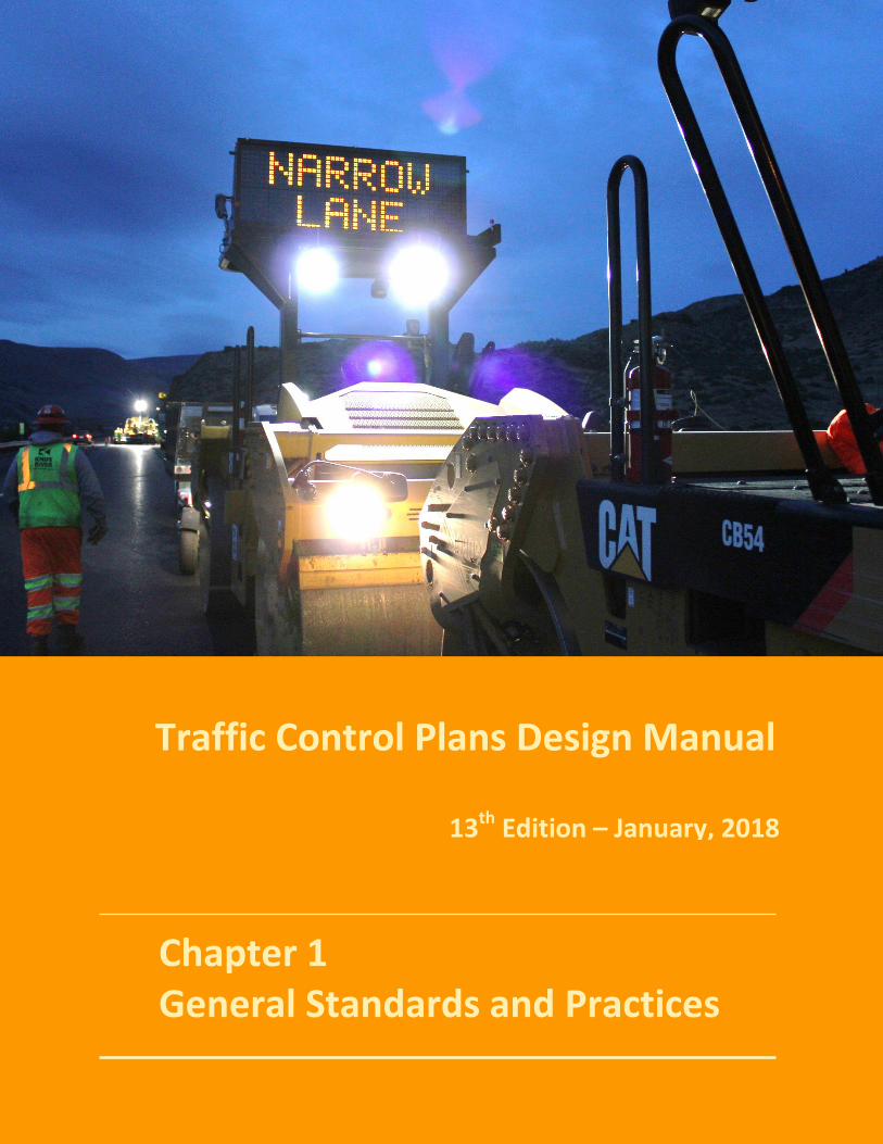
Traffic Control Plans Design Manual
13th Edition – January, 2018
Chapter 1 General Standards and Practices
Traffic Control Plans Design Manual 13th Edition
Oregon Department of Transportation 2 13th Edition, January 2018 Traffic Control Plans Unit Chapter 1
Table of Contents CHAPTER 1 GENERAL STANDARDS AND PRACTICES ________________________ 3
1.0 – KEY POINTS OF THIS CHAPTER ________________________________________________ 3 1.1 – WORK ZONE GUIDING PRINCIPLE ______________________________________________ 3
1.1.1 – GUIDING PRINCIPLE AND DECISION TREE APPLICATION _________________________ 6 1.2 – SAFETY – A PRIMARY FUNCTION ______________________________________________ 6
1.2.1 – SAFETY IN TCP DESIGN ___________________________________________________ 6 1.2.2 – ENGINEERING JUDGMENT ________________________________________________ 8
1.3 – TCP STANDARDS ___________________________________________________________ 8 1.3.1 – MANUAL ON UNIFORM TRAFFIC CONTROL DEVICES (MUTCD) ___________________ 8 1.3.2 – OAR & ORS ____________________________________________________________ 9 1.3.3 – ADDITIONAL STANDARDS & REFERENCES ____________________________________ 9
1.4 – TRANSPORTATION MANAGEMENT PLAN (TMP) _________________________________ 10 1.4.1 – TRANSPORTATION MANAGEMENT PLAN DOCUMENT _________________________ 11
1.5 – TRAFFIC CONTROL PLAN STRUCTURE __________________________________________ 11 1.5.1 – WORK ZONE LIMITS & COMPONENTS ______________________________________ 11 1.5.2 – TRAFFIC CONTROL PLAN DESIGN FORM ____________________________________ 14 1.5.3 – STANDARD SPECIFICATIONS & SPECIAL PROVISIONS __________________________ 15 1.5.4 – STANDARD DRAWINGS _________________________________________________ 16 1.5.5 – PROJECT-SPECIFIC CONSTRUCTION STAGING PLAN SHEETS _____________________ 16
1.6 – TRAFFIC CONTROL PLAN DESIGN _____________________________________________ 16 1.6.1 – DESIGN CONSIDERATIONS _______________________________________________ 16 1.6.2 – TRAFFIC CONTROL MEASURES ___________________________________________ 17 1.6.3 – PRIMARY DESIGN POLICIES ______________________________________________ 18
1.7 –WORK ZONE INTELLIGENT TRANSPORTATION SYSTEMS ___________________________ 19 1.7.1 – SMART WORK ZONE SYSTEMS ____________________________________________ 19
1.8 – TRAFFIC CONTROL DEVICES (TCD) ____________________________________________ 20 1.8.1 – USING TCD TO CREATE A SAFE WORK ZONE _________________________________ 20 1.8.2 – TCD PRINCIPLES _______________________________________________________ 20 1.8.3 – TCD CRASH TESTING ___________________________________________________ 20 1.8.4 – TCD CRASH TESTING CATEGORIES _________________________________________ 21 1.8.5 - THE QUALIFIED PRODUCTS LIST (QPL) ______________________________________ 22
1.9 – MOBILITY _______________________________________________________________ 23 1.9.1 – MOBILITY PROCEDURES MANUAL _________________________________________ 23 1.9.2 – COORDINATING TRAVEL DELAY ESTIMATES _________________________________ 23
1.10 – DESIGNER RESOURCES & WEB LINKS _________________________________________ 23 1.10.1 - TCP DESIGNER WEB LINKS ______________________________________________ 23 1.10.2 – TRAFFIC CONTROL PLAN CHECKLIST ______________________________________ 23
Traffic Control Plans Design Manual 13th Edition
Oregon Department of Transportation 3 13th Edition, January 2018 Traffic Control Plans Unit Chapter 1
Chapter
1 CHAPTER 1 GENERAL STANDARDS AND PRACTICES
1.0 – KEY POINTS OF THIS CHAPTER Safety – TCP Primary Function TCP Structure & Form TCP Design Elements TCP Designer Resources & Web Links
1.1 – WORK ZONE GUIDING PRINCIPLE Working with the Director’s Work Zone Safety Executive Steering Committee, the agency has developed and is implementing the Work Zone Guiding Principle:
Mission: ODOT’s mission is to provide a safe, efficient transportation system that supports economic opportunity and livable communities. Goal: Our work zone safety goal is zero fatalities and injuries, including ODOT employees, Contractors, public safety professionals and the traveling public while efficiently moving people and goods. Guiding Principle: The best work zone design and management plan will maintain safety and mobility, a balance that shall be analyzed continuously throughout the lifecycle of the facility. Directive/Strategy: To accomplish this goal, project design teams shall consider the full range of options including, but not limited to, separation of the traveling public from workers and work areas, speed reductions, law enforcement, enhanced traffic control devices and signage, and overall roadway and work zone design. Effective communication with travelers is essential to establish reasonable expectations and minimize unsafe driver behavior. While there is no single solution that is appropriate for all roadway designs and work zones, whenever practicable workers should be separated from traffic. Resources:
• ODOT’s Mobility Committee o A resource that can provide necessary balanced guidance. o Work through your mobility coordinator and the Mobility Committee to reach
resolution. o Bring issues forward early in the scoping and design stage to avoid surprises and
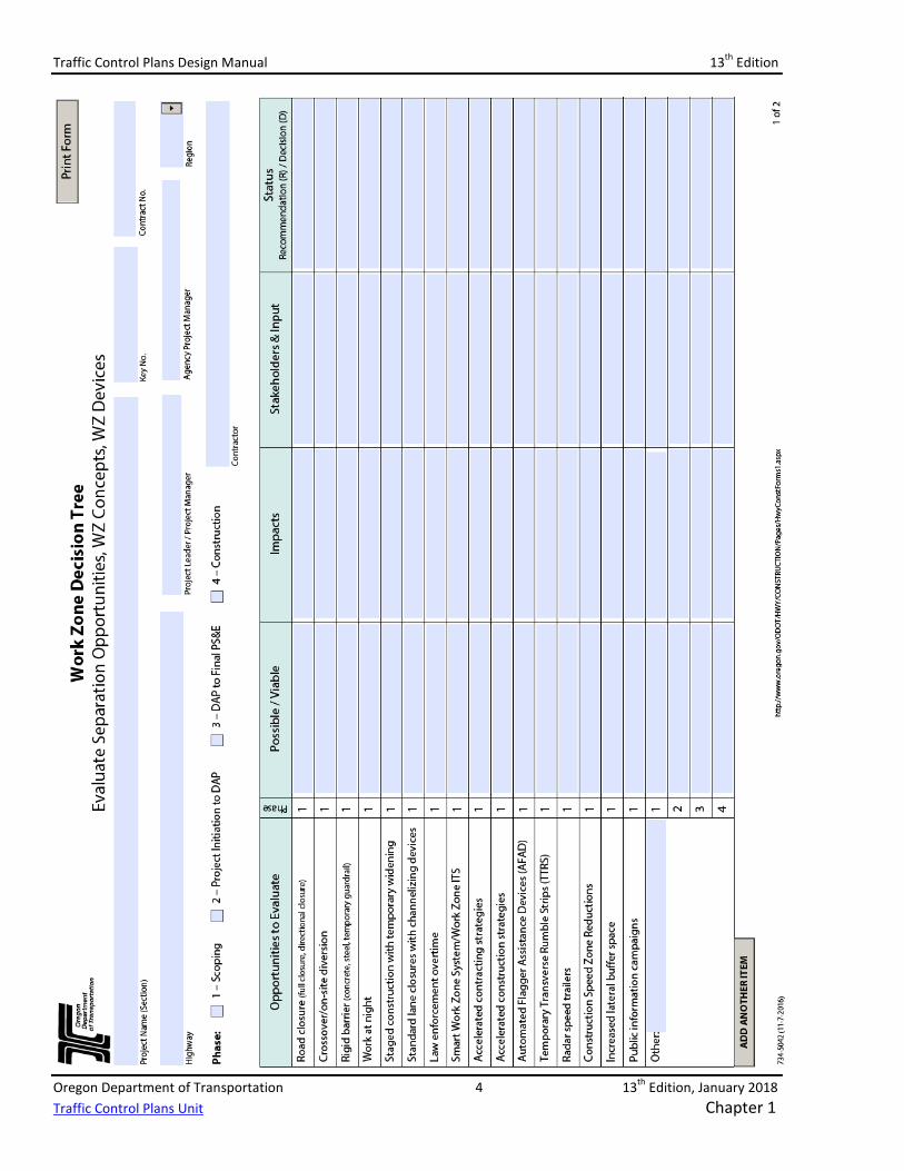
keep everyone in the problem solving mode. • Work Zone Decision Tree Form (see Chapter 3, and Appendix C - Forms)
o The Work Zone Decision Tree form is used to identify positive separation options available per work zone.
o Impacts to safety, mobility, scope, schedule, budget, delay, driver convenience, and ‘other’ impacts shall be identified when assessing separation options.
o During project development decision-making, the Work Zone Decision Tree form is intended to provide new tools and approaches.
Traffic Control Plans Design Manual 13th Edition
Oregon Department of Transportation 4 13th Edition, January 2018 Traffic Control Plans Unit Chapter 1
Traffic Control Plans Design Manual 13th Edition
Oregon Department of Transportation 5 13th Edition, January 2018 Traffic Control Plans Unit Chapter 1
1.1.1 – GUIDING PRINCIPLE AND DECISION TREE APPLICATION The Guiding Principle emphasizes ODOT highway work zones are to be managed through the life of a project – from initial scoping, during project development, and throughout construction. Safety for workers and public traffic must be an integral part of the traffic control plan design. That level of safety must be managed throughout the life of the project. Traffic mobility must also be designed into each project and managed through the life of the contract. The expectation for design teams is to apply the Guiding Principle and the Work Zone Decision Tree at key milestones throughout the course of the project – starting with Project Scoping.
Transportation Management Plan As part of the commitment to safety and project integrity, ODOT makes the Transportation Management Plan (TMP) a required portion of all ODOT highway construction contracts within public rights of way. ODOT is looking to increase the level of project planning, coordination and decision-making documentation for maintenance operations within future updates to the Oregon Temporary Traffic Control Handbook (OTTCH). See Section 1.4, below, for more information about the TMP, its development and minimum required contents.
1.2 – SAFETY – A PRIMARY FUNCTION 1.2.1 – SAFETY IN TCP DESIGN Safety is primary in TCP Design. Chapter 6 of the MUTCD repeatedly emphasizes safety management. ODOT’s perspective regarding the function of a TCP coincides with the fundamental principles, guidance and standards within the MUTCD. If designed with these ideas in mind, the TCP will minimize inconveniences to traffic during construction, minimize the number and severity of traffic crashes, and optimize safety and efficiency for highway workers. The principal function of a Traffic Control Plan (TCP) is to:
Provide for the reasonably safe and effective movement of road users through or around Temporary Traffic Control zones (work zones) while reasonably protecting road users, workers, responders to traffic incidents, and equipment.
The goal of a TCP is to route road users through or around a work zone efficiently by: • Using signs and pavement markings well in advance of the work zone, and adequately spaced
throughout the work zone; • Using devices that highlight or emphasize the appropriate path; • Avoiding frequent or abrupt changes in roadway geometry; and, • Avoiding work zone environments resulting in unanticipated, abrupt changes in speed.
ODOT, in accordance with the MUTCD, works to emphasize the purpose and function of a Traffic Control Plan and develop consistent, safe and effective TCP designs.
MUTCD DEFINITION OF A “TRAFFIC CONTROL PLAN” – Chapter 6A From Chapter 6 of the MUTCD, the following excerpts discuss the definition and function of a temporary traffic control plan.
Traffic Control Plans Design Manual 13th Edition
Oregon Department of Transportation 6 13th Edition, January 2018 Traffic Control Plans Unit Chapter 1
At the Planning level: “When the normal function of the roadway is suspended, TTC (temporary traffic control) planning provides for continuity of the movement of motor vehicle, bicycle, and pedestrian traffic (including accessible passage); transit operations; and access (and accessibility) to property and utilities.”
For worker safety: “Of equal importance to the public traveling through the TTC zone is the safety of workers performing the many varied tasks within the work space. TTC zones present constantly changing conditions that are unexpected by the road user. This creates an even higher degree of vulnerability for the workers and incident management responders on or near the roadway. At the same time, the TTC zone provides for the efficient completion of whatever activity interrupted the normal use of the roadway.”
The overall picture: Consideration for road user safety, worker and responder safety, and the efficiency of road user flow is an integral element of every TTC zone, from planning through completion. A concurrent objective of the TTC is the efficient construction and maintenance of the highway and the efficient resolution of traffic incidents.
THE TRAFFIC CONTROL PLAN When conducting road work or working within the public right of way in Oregon, a traffic control plan is required. For ODOT highway construction contracts, the traffic control plan must include, as a minimum:
• Standard Specifications for Construction and Boilerplate Special Provisions • A list of anticipated Pay Items • A list of applicable ODOT Standard Drawings and Standard Details
Project-specific traffic control plan sheets are recommended or required when projects include: • Complex Scopes of Work – including multiple shifts in traffic, or where describing the
activities in project-specific Special Provisions would be impractical • Full or partial facility closures – including motor vehicle, bicycle and pedestrian facilities –
where a detour is included to reroute roadway users • Pedestrian-specific construction staging or Temporary Pedestrian Accessible Routes • Challenging site locations or conditions
Where additional details are needed to add clarity to improve the constructability of the project, development of project-specific plan sheets is encouraged. Include diagrams and engineered drawings to help convey the intended use and placement of traffic control measures and devices. The development of site-specific drawings may not be required for all projects or work activities; but, drawings should be considered for activities or locations where the additional detail would enhance the overall safety for the work area and increase the ease in which the plan is implemented in the field.
Traffic Control Plans Design Manual 13th Edition
Oregon Department of Transportation 7 13th Edition, January 2018 Traffic Control Plans Unit Chapter 1
Typical Applications from Chapter 6 of the MUTCD, Typical Application Diagrams from Chapter 5 of the Oregon Temporary Traffic Control Handbook (OTTCH), and ODOT Traffic Control Standard Drawings (TM800 Series) are intended to provide generic, non-project-specific temporary traffic control layouts for a variety of work zone conditions and roadway environments.
1.2.2 – ENGINEERING JUDGMENT From the MUTCD, Chapter 1, FHWA provides the following definition for “Engineering Judgment”:
The evaluation of available pertinent information and the application of appropriate principles, provisions, and practices as contained in this Manual and other sources, for the purpose of deciding upon the applicability, design, operation, or installation of a traffic control device. Engineering judgment shall be exercised by an engineer, or by an individual working under the supervision of an engineer, through the application of procedures and criteria established by the engineer. *Documentation of engineering judgment is not required.
A TCP Designer should use engineering judgment when adding details to the TCP to improve clarity and efficiency; and, avoid excessive delays, added costs, and improve safety.
* While being founded on baseline principals or thresholds, some additions or modificationsto the TCP may be based largely on an Engineer’s individual experiences and not bepreviously documented. If invoking engineering judgment to make additions to the TCP, theengineer’s decision process and final recommendation or solution should be well-documented including relevant assumptions. See Transportation Management Plans inSection 1.4, below.
1.3 – TCP STANDARDS 1.3.1 – MANUAL ON UNIFORM TRAFFIC CONTROL DEVICES (MUTCD) ODOT uses the guidance of the Federal Highway Administration (FHWA) MUTCD in the design of temporary traffic control plans. Mandates within the Oregon Administrative Rules (OAR) and the Oregon Revised Statutes (ORS) require the use of the MUTCD as the reference for the specifications of uniform standards for traffic control devices for use upon highways within this state. MUTCD Section 6A.01 states:
“The needs and control of all road users (motorists, bicyclists, and pedestrians within the highway, including persons with disabilities in accordance with the Americans with Disabilities Act of 1990 (ADA), Title II, Paragraph 35.130) through a TTC zone shall be an essential part of highway construction, utility work, maintenance operations, and the management of traffic incidents.”
MUTCD Section 6B.01 states: “A TTC plan, in detail appropriate to the complexity of the work project or incident, should be prepared and understood by all responsible parties before the site is occupied.”
Together, the MUTCD and the applicable OAR and ORS form the basis for requiring that a temporary traffic control plan be prepared for all construction or maintenance work within Oregon State highway right of way.
Traffic Control Plans Design Manual 13th Edition
Oregon Department of Transportation 8 13th Edition, January 2018 Traffic Control Plans Unit Chapter 1
1.3.2 – OAR & ORS The following Oregon Administrative Rules (OAR) and Oregon Revised Statutes (ORS) pertain to work zone and construction area traffic control:
• OAR 734-020-0005 adopts the MUTCD as the reference for the specifications of uniformstandards for traffic control devices for use upon highways within this state.
• OAR 734-020-0410 requires the State Traffic Engineer’s approval of all traffic signals,temporary, portable, or permanent.
• ORS 811.230, .231, .232, and .233 cover double fines and yielding to highway workers.
A TCP Designer should be familiar with these and other OAR and ORS that pertain to work zone and construction area activities.
1.3.3 – ADDITIONAL STANDARDS & REFERENCES A number of additional resources are available and are regularly used in developing a traffic control plan. The following references should be used to help maintain consistency and uniformity in the design and implementation of a temporary traffic control plan.
• FHWA Standard Highway Signs (SHS) manual and SHS Supplement – Includes sign designs forregulatory, warning, guidance and service signing regularly used in TCPs.
• FHWA Applying the Americans with Disabilities Act in Work Zones: A Practitioner Guide –Includes overview of requirements and guidance within 1990 ADA, the Proposed Right ofWay Accessibility Guidelines (PROWAG), and MUTCD regarding accommodation, protectionand mobility of ADA and pedestrians within a work zone.
• AASHTO Roadside Design Guide – Includes concepts and general discussions about “clearzone”, longitudinal barrier systems, impact attenuators and other safety hardware devices.
• 2010 Americans with Disabilities Act (ADA) and ADA Title II – ADA Standards are issued by the(US) Department of Justice (DOJ) and the Department of Transportation (DOT), and apply tofacilities covered by the ADA in new construction and alterations.
• 2011 Proposed Rights of Way Accessibility Guidelines (PROWAG) – While not formallyadopted into Federal Law, under Chapter R1, Section R101, the following should be noted:
“Compliance with this document is mandatory when required by regulations issued by federal agencies that include accessibility standards for the design, construction, and alteration of pedestrian facilities in the public right-of-way.”
• ODOT Sign Policy & Guidelines – Includes designs and functions for regulatory, warning,guidance and service signs specific to Oregon – modifying or supplementing MUTCD and SHS.
• ODOT Temporary Traffic Control Handbook for Operations of Three Days or Less (OTTCH) –While not intended for long-duration roadwork activities, the OTTCH is based on thefundamental principles and standards within the MUTCD as well as Oregon-specific trafficcontrol measures. The OTTCH is intended for work zone activities lasting less than threeconsecutive days – including mobile operations – for both freeways and non-freewayfacilities.
Traffic Control Plans Design Manual 13th Edition
Oregon Department of Transportation 9 13th Edition, January 2018 Traffic Control Plans Unit Chapter 1
• ODOT Portable Changeable Message Sign (PCMS) Handbook – Includes useful informationregarding the function, application and proper operation of this valuable traffic controldevice.
• ODOT Highway Design Manual (HDM) – While primarily used for the design of permanentroadway facilities, the HDM includes valuable information in the design of temporaryroadway alignments and other features.
• ODOT Transportation Management Plan (TMP) Project-Level Guidance Manual – Includesinformation useful in developing the TMP, and documenting project design and work zonesafety enhancement decisions.
1.4 – TRANSPORTATION MANAGEMENT PLAN (TMP) FHWA ‘FINAL RULE ON WORK ZONE SAFETY and MOBILITY’ – 23 CFR 630 SUBPART J Published on September 9, 2004, the Federal Highway Administration released updates to the work zone safety regulations under 23 CFR 630 Subpart J – referred to now as the, “Final Rule on Work Zone Safety and Mobility.” The complete Rule is available on the FHWA web site under the, “Resources” web page of the “Work Zone” section. Search for, “Work Zone Safety and Mobility” or, “23 CFR 630 Subpart J”.
The Rule updates and broadens the former regulation at 23 CFR 630 Subpart J to address more of the current issues affecting work zone safety and mobility. The changes to the regulation encourage the broader consideration of the safety and mobility impacts of work zones across project development and the implementation of strategies that help manage these impacts during project delivery.
The updated rule applies to all State and local governments that receive Federal-aid highway funding. All of these agencies were required to comply with the provisions of the rule no later than October 12, 2007.
A key requirement in the Rule is the development and inclusion of a Transportation Management Plan (TMP) as part of the project development and contract administration processes. The FHWA has identified two different categories for a TMP.
Within the New Rule language, a “Significant Project” is one that meets the following criteria: • “…alone, or in combination with other concurrent projects nearby, is anticipated to
cause sustained work zone impacts that are greater than what is considered tolerablebased on State policy and/or engineering.”
• Project is on an Interstate highway within a designated Transportation ManagementArea (TMA).
ODOT added a third criterion that would identify a project as being a, “Significant Project”: • All projects with a construction budget of $5 million or more.
As a “Significant Project,” the TMP must include all of the following: • A temporary Traffic Control Plan (TCP)
Traffic Control Plans Design Manual 13th Edition
Oregon Department of Transportation 10 13th Edition, January 2018 Traffic Control Plans Unit Chapter 1
• Transportation Operation (TO) strategies – Efforts to minimize or mitigate traffic congestion,delay, volumes, peak hour surges, etc., during construction
• Public Information (PI) campaigns – Communication strategies to notify affectedstakeholders and the traveling public, and inform them of project schedules, changes,alternate routes and mobility options.
For a project that does not qualify as a “Significant Project,” the FHWA still recommends agencies consider including both TO and SI strategies in their TMPs, when practical. Documentation should still be kept for all design decisions that affect the TCP and construction schedule.
1.4.1 – TRANSPORTATION MANAGEMENT PLAN DOCUMENT The TMP should be considered as the “project diary” – used by the agency to document and track critical design and implementation decisions made over the course of project development and throughout the implementation of the TCP. TMP development should begin as early as the Project Scoping phase. The Transportation Management Plan (TMP), and the amount of detail within it, is relative to a project’s scope of work – the more complex the project, the more details and information should be included in the TMP. The ODOT Transportation Management Plan Project-Level Guidance Manual is available on ODOT’s Work Zone Traffic Control website. The TMP Guidance Manual should be used as a template to develop the TMP for an ODOT highway construction project.
ODOT TMP MINIMUM REQUIREMENTS For any ODOT project – identified as a “Significant project” or not - at a minimum, TMPs must include the following:
• A traffic control plan• A narrative explaining the Scope of Work, work location and duration details; how selected
traffic control measures and devices are being used to protect workers and road users.• A delay estimate for all projects on State Highways with delay thresholds• An evaluation of the delay impacts, including a discussion of the impact differences between
the different options explored• Copies of the Work Zone Decision Tree form for each project development milestone:
• Scoping• Project Initiation• DAP
• Advance Plans• Plans, Specifications & Estimates (PS&E)
• Copies of the Work Zone Decision Tree form during Construction, as developed
The Work Zone Decision Tree form is used to document positive separation and safety enhancement alternatives explored, reasons for rejection/advancement, and final decisions made regarding:
• Construction Staging alternatives• Positive Separation opportunities• Traffic Control Measures
However, the TMP should also include discussion of other temporary traffic control plan related topics, including:
Traffic Control Plans Design Manual 13th Edition
Oregon Department of Transportation 11 13th Edition, January 2018 Traffic Control Plans Unit Chapter 1
• Specific materials, equipment needs, or construction techniques• Sensitive timeframes, critical project components, or other scheduling constraints• Stakeholder agreements• Constructability concerns• Budgetary compromises• Project site conditions/restrictions
For “Significant Projects”, the Public Information and Traffic Operations and demand management strategies would also be included as part of the TMP document. Because the TMP is considered a ‘living document’, it will continue to grow and evolve throughout the life of the project development process. Therefore, as the project design evolves, the TMP should be regularly updated with new information that could affect the final design or the implementation of the Traffic Control Plan during constructions. The documented information within the TMP – including decisions included on the Work Zone Decision Tree form, stakeholder partnership agreements, traffic control measures, and staging options – can be recalled, as needed, once construction has begun. If a proposal is made to modify the TCP, staging or construction schedule, TMP contents can be used to support documented design decisions, protect the integrity of the TCP, project schedule, and stakeholder agreements. TMP contents are ultimately used to minimize traffic delays and provide a safe, efficient work zone for road users and construction workers. Upon completion of the design – during the “Plans, Specs & Estimate” (PS&E) phase - the TMP should be distributed to Project Team members (including Consultant staff) and the agency’s Construction Project Manager or Coordinator. ODOT intends to include the TMP in the bidding documents. A copy of the completed TMP will be included in the Bid Documents, and a copy distributed to the ODOT Project Manager.
1.5 – TRAFFIC CONTROL PLAN STRUCTURE 1.5.1 – WORK ZONE LIMITS & COMPONENTS WORK ZONE LIMITS Because Oregon enforces the doubling of traffic fines in highway construction work zones, it is important to clearly identify the beginning and end of a work zone for the travelling public, contractors and law enforcement agencies. The MUTCD, Part 6, Section 6C.02; the Standard Specifications for Construction, Section 00225.01; and, the Oregon Vehicle Code (ORS 811.230) define the limits of a work zone as follows:
“…from the first warning sign or high-intensity rotating, flashing, or strobe lights on a vehicle to the ‘END ROAD WORK’ sign or the last (traffic control) device.”
It is the intention of ODOT and this Design manual to clarify, “first warning sign” as meaning the initial, “ROAD WORK AHEAD” (W20-1) or similar advance warning sign (e.g. “BRIDGE WORK AHEAD”, “SHOULDER WORK AHEAD”, “UTILITY WORK AHEAD”).
Traffic Control Plans Design Manual 13th Edition
Oregon Department of Transportation 12 13th Edition, January 2018 Traffic Control Plans Unit Chapter 1
For the purposes of discussion and enforcement, the “first” or initial warning sign does not include the following: The standard, “ROAD WORK NEXT XX MILES” sign The standard, “INTERMITTENT ROAD WORK NEXT XX MILES” sign Messages displayed on electronic signs – e.g. PCMS or VMS
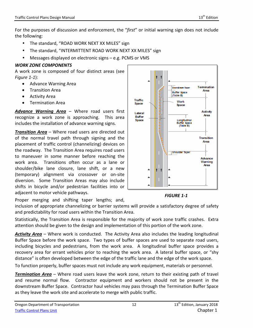
WORK ZONE COMPONENTS A work zone is composed of four distinct areas (see Figure 1-1):
• Advance Warning Area• Transition Area• Activity Area• Termination Area
Advance Warning Area – Where road users first recognize a work zone is approaching. This area includes the installation of advance warning signs.
Transition Area – Where road users are directed out of the normal travel path through signing and the placement of traffic control (channelizing) devices on the roadway. The Transition Area requires road users to maneuver in some manner before reaching the work area. Transitions often occur as a lane or shoulder/bike lane closure, lane shift, or a new (temporary) alignment via crossover or on-site diversion. Some Transition Areas may also include shifts in bicycle and/or pedestrian facilities into or adjacent to motor vehicle pathways. Proper merging and shifting taper lengths; and, inclusion of appropriate channelizing or barrier systems will provide a satisfactory degree of safety and predictability for road users within the Transition Area. Statistically, the Transition Area is responsible for the majority of work zone traffic crashes. Extra attention should be given to the design and implementation of this portion of the work zone.
Activity Area – Where work is conducted. The Activity Area also includes the leading longitudinal Buffer Space before the work space. Two types of buffer spaces are used to separate road users, including bicycles and pedestrians, from the work area. A longitudinal buffer space provides a recovery area for errant vehicles prior to reaching the work area. A lateral buffer space, or “shy distance” is often developed between the edge of the traffic lane and the edge of the work space. To function properly, buffer spaces must not include any work equipment, materials or personnel.
Termination Area – Where road users leave the work zone, return to their existing path of travel and resume normal flow. Contractor equipment and workers should not be present in the downstream Buffer Space. Contractor haul vehicles may pass through the Termination Buffer Space as they leave the work site and accelerate to merge with public traffic.
FIGURE 1-1
Traffic Control Plans Design Manual 13th Edition
Oregon Department of Transportation 13 13th Edition, January 2018 Traffic Control Plans Unit Chapter 1
OTHER WORK ZONE COMPONENTS Additional elements are frequently used in the development of a traffic control plan, but are often more project-specific, including:
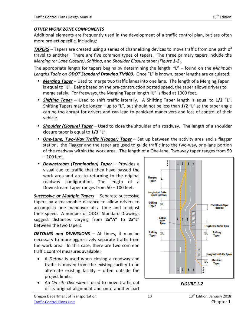
TAPERS – Tapers are created using a series of channelizing devices to move traffic from one path of travel to another. There are five common types of tapers. The three primary tapers include the Merging (or Lane Closure), Shifting, and Shoulder Closure taper (Figure 1-2). The appropriate length for tapers begins by determining the length, “L” – found on the Minimum Lengths Table on ODOT Standard Drawing TM800. Once “L” is known, taper lengths are calculated: Merging Taper – Used to merge two traffic lanes into one lane. The length of a Merging Taper
is equal to “L”. Being based on the pre-construction posted speed, the taper allows drivers tomerge safely. For freeways, the Merging Taper length “L” is fixed at 1000 feet.
Shifting Taper – Used to shift traffic laterally. A Shifting Taper length is equal to 1/2 “L”.Shifting Tapers may be longer – up to “L”, but should not be less than 1/2 “L” as the taper anglecan be too abrupt for drivers and can lead to panicked maneuvers and loss of control of theirvehicle.
Shoulder (Closure) Taper – Used to close the shoulder of a roadway. The length of a shoulderclosure taper is equal to 1/3 “L”.
One-Lane, Two-Way Traffic (Flagger) Taper – Set up between the activity area and a flaggerstation, the Flagger and the taper are used to guide traffic into the two-way, one-lane portionof the roadway within the work area. The length of a One-lane, Two-way taper ranges from 50– 100 feet.
Downstream (Termination) Taper – Provides avisual cue to traffic that they have passed thework area and are to returning to the originalroadway configuration. The length of aDownstream Taper ranges from 50 – 100 feet.
Successive or Multiple Tapers – Separate successive tapers by a reasonable distance to allow drivers to accomplish one maneuver at a time and readjust their speed. A number of ODOT Standard Drawings suggest distances varying from 2x”A” to 2x”L” between the two tapers.
DETOURS and DIVERSIONS – At times, it may be necessary to more aggressively separate traffic from the work area. In this case, there are two common traffic control measures available: • A Detour is used when closing a roadway and
traffic is moved from the existing facility to analternate existing facility – often outside theproject limits.
• An On-site Diversion is used to move traffic outof its original alignment and onto another part
FIGURE 1-2
Traffic Control Plans Design Manual 13th Edition
Oregon Department of Transportation 14 13th Edition, January 2018 Traffic Control Plans Unit Chapter 1
of the existing roadway; or, onto a temporary surface constructed within the project right-of-way or easement (Figure 1-2). Traffic is diverted around the work area often using a combination of signing, channelizing devices, barrier, and pavement markings.
On-site Diversions can be configured to accommodate all existing traffic lanes, a reduced number of lanes; or, a single, reversible lane controlled by a temporary traffic signal or flagging operations.
1.5.2 – TRAFFIC CONTROL PLAN DESIGN FORM A Traffic Control Plan can take one of two basic forms – a Written TCP or, a TCP with Plan Sheets. A Written TCP includes project-specific Special Provisions and applicable ODOT Standard Drawings. Written TCPs are common for projects with the following attributes:
• Construction details and instructions can be conveyed solely using specification language andStandard Drawings
• Project duration is shorter – typically less than a few months• Scope of work is simple and may only include a few work activities (e.g. preservation work, or
a shoulder widening project)A “TCP with Plan Sheets” should be developed for projects with the following attributes:
• All work activities cannot easily be described solely using project-specific Special Provisionsor Standard Drawings
• Scope of work is complex and requires multiple, site-specific Stages; and, is typically muchlonger – several months to a year or more
• Construction features or activities are challenging and labor-intensive (e.g. bridgereplacement, culvert installation, full roadway rebuilds, roadway realignments, signalizedintersection/ramp terminal reconstructions)
• A detour route is included as part of the project
TCPs with Plan Sheets add necessary project-specific details and instructions for Contractors not addressed through Standard Drawings or Specifications. Project-specific plan sheets can provide additional detail for:
• Bridge replacements or culvert installations• Interchange modifications and ramp terminal reconstructions• Full-depth roadway rebuilds or realignments• Full roadway closures with detour routes• Intersection rebuilds or new signal installations with mitigations for pedestrian accessibility
impacts
Traffic Control Plans Design Manual 13th Edition
Oregon Department of Transportation 15 13th Edition, January 2018 Traffic Control Plans Unit Chapter 1
1.5.3 – STANDARD SPECIFICATIONS & SPECIAL PROVISIONS The ODOT/APWA Standard Specifications for Construction, Boilerplate Special Provisions, and applicable Standard Drawings are part of every TCP and are the primary elements that explain how work is to be completed. Chapter 4 – Specifications and Standard Drawings explains in greater detail the format, function, writing and editing of Specifications and project-specific Special Provisions. Chapter 4 also discusses Standard Drawing content and function. The following are meant as brief introductions to these valuable tools in developing a safe, efficient, and effective temporary traffic control plan.
STANDARD SPECIFICATIONS The collection of Standard Specifications for Construction, commonly referred to as the “Standard Specs,” is available in hard copy form and on-line on the ODOT web site under the Specifications Unit located within the Traffic-Roadway Section. The current version of the Standard Specifications for Construction is the 2018 edition – to be used for projects letting for contract beginning December 1, 2017. Projects currently under contract, or with a bid date prior to December 1, 2017, will still be using the 2015 Standard Specifications. The Standard Specifications and Boilerplate Special Provisions apply to all ODOT highway construction contracts. However, Designers are reminded that the Standard Specifications for Construction are also applicable to local Public Works agencies (e.g. Cities and Counties).
BOILERPLATE SPECIAL PROVISION The Specifications Unit website includes links to documents known as the Boilerplate Special Provisions. Boilerplate Special Provisions have been developed to accomplish the following:
• Provide additional project-specific instructions for the Contractor • Identify important and relevant details on Standard Drawings or on project-specific plan
sheets • Supplement the contents of the Standard Specifications for Construction • Update language that has changed or become obsolete in the Standard Specifications for
Construction, since its publication
Boilerplates are available on the Specification Unit website for downloading, editing and publishing within contract bid document packages.
“UNIQUE” SPECIAL PROVISIONS When the 2018 Standard Specifications for Construction was updated, all of the “Unique” Special Provisions for Section 00220 and Section 00225 were incorporated into the respective Boilerplate Special Provision documents. As a result, links on the Specifications Unit website to the “Uniques” under Section 00220 and 00225 have been deleted. As the 2018 Standard Specifications for Construction and Boilerplate Special Provisions are used and incorporated into more and more projects, the need for additional Special Provision language will likely arise. Contact the Work Zone Traffic Control Unit to discuss the need for additional Boilerplate language.
Traffic Control Plans Design Manual 13th Edition
Oregon Department of Transportation 16 13th Edition, January 2018 Traffic Control Plans Unit Chapter 1
CUSTOM PROJECT-SPECIFIC SPECIAL PROVISIONS Custom Special Provisions are drafted from scratch and include language to address the needs of one specific project – language not otherwise available in the Standard Specifications or Boilerplate Special Provisions. Custom Special Provisions are not very common often because language within the Standard Specifications or Boilerplate Special Provisions can be modified to suit the specific need.
1.5.4 – STANDARD DRAWINGS Oregon Standard Drawings are engineered products developed by ODOT for use on public roadways in Oregon. The Standard Drawings used for temporary traffic control in work zones are included under the TM800 – Temporary Traffic Control drawing series. The TM800 Series drawings are available on the ODOT Engineering web site under the “Standard Drawings and Details” link. See Chapter 4 for additional Standard Drawing information.
1.5.5 – PROJECT-SPECIFIC CONSTRUCTION STAGING PLAN SHEETS Complex projects, and those that include more complex design features, make it impractical to rely solely on Standard Drawings and Special Provision language to relay vital and necessary construction staging information to the Contractor to help ensure road user safety, mobility, and accessibility. Under these circumstances, developing project-specific construction staging plan sheets - commonly referred to as “Plan sheets” – significantly enhances the success and effectiveness of the TCP. Plan sheets are used to describe how the existing roadway area is to be divided between live traffic and the active construction area. Plan sheets also identify the types, quantities and locations for the variety of temporary traffic control devices often included in the TCP. See Chapter 5 for additional temporary traffic control plan sheet information.
1.6 – TRAFFIC CONTROL PLAN DESIGN 1.6.1 – DESIGN CONSIDERATIONS Chapter 3 – Traffic Control Measures provides greater detail regarding the wide variety of issues, factors, considerations, and details a Designer must process before and during the design of the TCP.
Information in this Chapter can be used to focus a Designer’s attention on the broader questions – What, Where, When, How and Why – to help them develop a safe, effective, efficient, and biddable temporary traffic control plan.
The following should be considered as the most critical components in optimizing the design for a temporary traffic control plan:
• SITE INVESTIGATIONTake the opportunity to learn as much as practical about the exiting features and operationsof the project site. Site investigations are invaluable to the designer to get firsthandknowledge of the project site and create accurate traffic control plans. Site investigationsshould be completed for all projects.
• SCOPE of WORKUnderstanding the goal of the project, the finished products and any constructability issuesassociated with completing the project on-time and on-budget.
Traffic Control Plans Design Manual 13th Edition
Oregon Department of Transportation 17 13th Edition, January 2018 Traffic Control Plans Unit Chapter 1
Chapter 3 includes a number of specific Scope of Work examples and questions the Designer should be asking as they start developing their TCP.
Once the Designer has a confident understanding of both the project site and the scope of work, the Designer can begin looking at the various opportunities for safely managing road users through or around the work zone; and, optimizing the safety and efficiency for the workers.
WORK ZONE DECISION TREE FORM For each project, Designers should begin with the Work Zone Decision Tree form as part of their design documentation process and safety enhancement opportunity analyses identified in the ODOT TMP Guidance Document. The Work Zone Decision Tree form offers Designers a systematic process for analyzing the variety of traffic control measures available for each project. The form can be used to help evaluate each option under various conditions, and determine the feasibility of each option. The Designer can document decisions made regarding the selection or rejection of each option, and reasons supporting those decisions, on the form. See Chapter 3 for additional Work Zone Decision Tree form information; and, Appendix C for a copy of the current form. Both the ODOT TMP Project-Level Guidance Manual and the Work Zone Decision Tree form are available on the ODOT Work Zone Traffic Control Unit website.
1.6.2 – TRAFFIC CONTROL MEASURES In developing a TCP, there are several tools and strategies the Designer may employ to optimize the safety and effectiveness of the work zone for all road users and highway workers. Commonly referred to as Traffic Control Measures (TCM), they can vary from a single traffic control device to the deployment of a complex array or sequence of devices. TCM EXAMPLES:
• Paving Operations: Temporary traffic delineation may be accomplished using tubularmarkers, conical markers, plastic drums, temporary flexible pavement markers, eventemporary paint – depending on the facility type and timing between temporary delineationand placement of permanent markings.
• Bridge Replacements: A limited-duration full road closure with a detour may be used insteadof staged bridge construction with 24-hour flagging or a temporary traffic signal to bettermanage traffic capacities and worker safety.
• On-Site Diversions: A single-lane temporary roadway diversion with a temporary signal ateach end; or, a two-lane, free-flow diversion may each be investigated as a viable TCM for aculvert or bridge replacement project.
See Chapter 3 for additional Traffic Control Measure information and details – including additional examples of effective TCM used to develop safe and effective TCPs.
Traffic Control Plans Design Manual 13th Edition
Oregon Department of Transportation 18 13th Edition, January 2018 Traffic Control Plans Unit Chapter 1
1.6.3 – PRIMARY DESIGN POLICIES The design of a temporary traffic control plan requires engineering experience and judgment when determining the use or application of a given safety measure or construction strategy. Design standards and practices must also be applied to ensure consistency, and optimize safety and mobility within the work zone. This manual identifies these standards to emphasize the need for regular and consistent use in TCP design. The following Design Policies are used to produce safe, consistent and efficient work zones for all road users and construction contractors. See Chapter 3 for design policy application details and examples.
• GUIDING PRINCIPLE and WORK ZONE DECISION TREE FORM The goal and objectives of the ODOT Guiding Principle is to be applied throughout the life of the project’s development and construction. The Work Zone Decision Tree form is to be used for each project, and addressed at each of the project’s key milestones to identify and document safety enhancement opportunities.
• DESIGN SPEED The pre-construction posted speed is used as the Design Speed for many TCP design values, including:
• Temporary alignment designs (e.g. on-site diversions, crossovers) • Temporary sign and device spacing • Taper lengths for lane closures and shifts, and shoulder closures • Impact attenuator selection
• SIGN AND DEVICE SPACING The following values are used for spacing of channelizing traffic control devices (TCD) including plastic drums, conical and tubular markers:
• 10 feet – For intersection or access radii • 20 feet – For speeds < 40 mph (Recommend 10 ft. spacing for speeds < 30 mph) • 40 feet – For speeds > 45 mph (Including freeways)
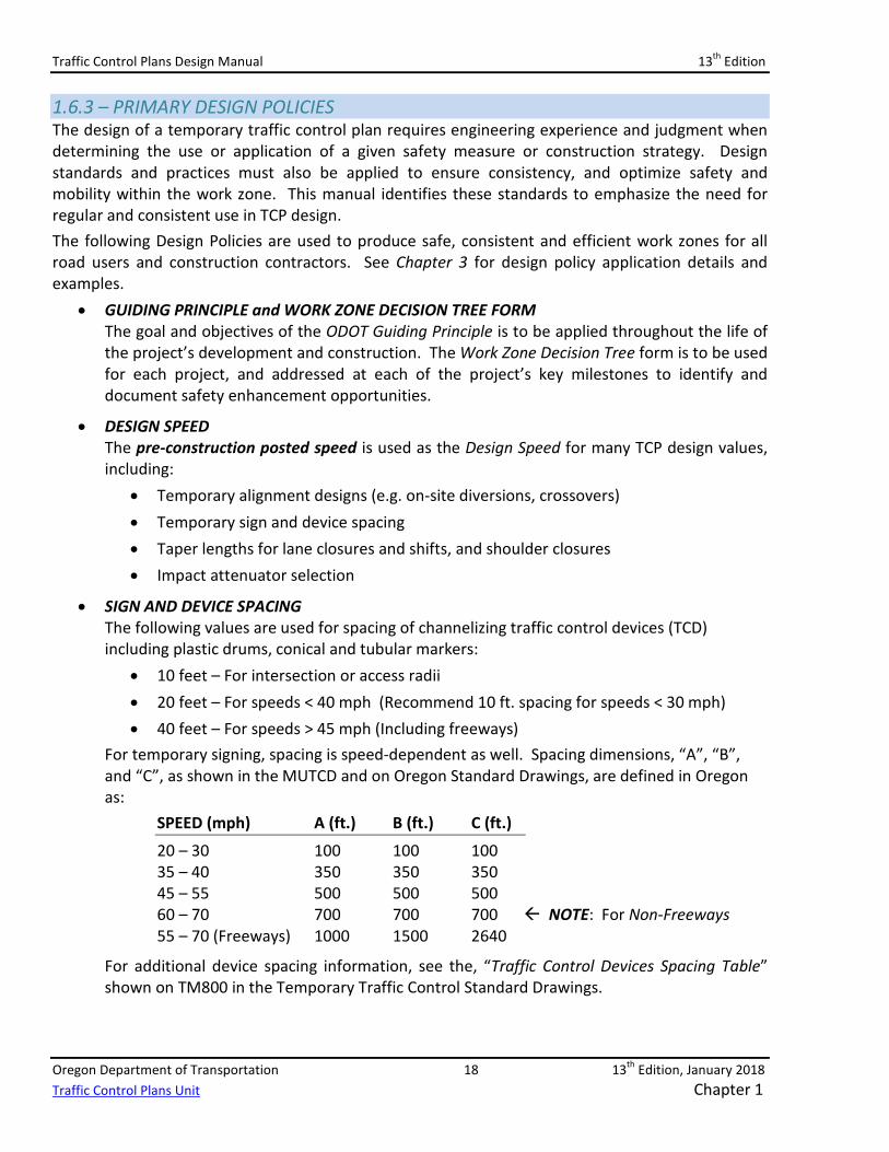
For temporary signing, spacing is speed-dependent as well. Spacing dimensions, “A”, “B”, and “C”, as shown in the MUTCD and on Oregon Standard Drawings, are defined in Oregon as:
SPEED (mph) A (ft.) B (ft.) C (ft.)
20 – 30 100 100 100 35 – 40 350 350 350 45 – 55 500 500 500 60 – 70 700 700 700 NOTE: For Non-Freeways 55 – 70 (Freeways) 1000 1500 2640
For additional device spacing information, see the, “Traffic Control Devices Spacing Table” shown on TM800 in the Temporary Traffic Control Standard Drawings.
Traffic Control Plans Design Manual 13th Edition
Oregon Department of Transportation 19 13th Edition, January 2018 Traffic Control Plans Unit Chapter 1
• FREIGHT MOBILITY Minimum horizontal roadway widths and vertical height constraints for work zones are critical to statewide freight mobility. See Chapter 3 for horizontal widths and vertical height design details.
• BICYCLE AND PEDESTRIAN ACCOMMODATION In developing a comprehensive TCP, the design must incorporate safety, mobility and accessibility needs for all road users – bicyclists, pedestrians and ADA road users – through the selected features, alignments, guidance, surfaces and safety appurtenances.
To optimize TCP designs, ODOT uses this manual, current Standard Drawings and guidance from FHWA sources – including the FHWA Applying the Americans with Disabilities Act in Work Zones: A Practitioner Guide – available in Appendix E and on ODOT Traffic Control Plans Unit website.
1.7 –WORK ZONE INTELLIGENT TRANSPORTATION SYSTEMS 1.7.1 – SMART WORK ZONE SYSTEMS Advances in technology have made it possible to monitor traffic conditions and construction operations, and relay that information to road users in real time. Oregon and other agencies across the U.S. are using this technology in permanent locations to monitor traffic and alert motorists of changing roadway conditions ahead. This same technology, however, can also be used within the work zone environment as a temporary feature. ODOT currently uses permanent Intelligent Transportation Systems (ITS) to report real-time roadway conditions on major state highways (see www.tripcheck.com). ODOT uses permanently installed communication equipment such as Variable Message Signs (VMS) to alert the traveling public of potential congestion, delays, emergency situations and Amber Alerts. ODOT is adapting these permanent technologies for use in its temporary highway construction work zones. Using Portable Changeable Message Signs (PCMS), portable traffic sensors and other system components, ODOT aims to provide real-time alerts, travel time data, and detailed work zone information to approaching motorists. ODOT has defined these new temporary work zone systems as, “Smart Work Zone Systems” (SWZS). Oregon has recently demonstrated these systems on a handful of select projects. ODOT has included a number of the successfully tested systems on its Qualified Products Lies (QPL) and is encouraging their inclusion into many of ODOT’s future highway construction contracts. SWZS used in Oregon work zones will be designed to measure fluctuating traffic volumes and speeds within the work zone. Using predetermined thresholds, the SWZS can then relay applicable warnings or other project-specific information to approaching motorists. Through the use of the SWZS, ODOT hopes to improve overall work zone safety by reducing crashes and injuries, by minimizing traffic delay, and improving response time should there be a work zone incident. Chapter 3 includes additional SWZS information.
Traffic Control Plans Design Manual 13th Edition
Oregon Department of Transportation 20 13th Edition, January 2018 Traffic Control Plans Unit Chapter 1
1.8 – TRAFFIC CONTROL DEVICES (TCD) 1.8.1 – USING TCD TO CREATE A SAFE WORK ZONE Traffic Control Devices are used to regulate, warn, and guide traffic safely through a work zone. When there is consistent, uniform usage of TCD, work zone safety is increased. A safe, efficient and uniform work zone performs two vital functions:
• Reduces the frequency of accidents • Reduces the severity of accidents
1.8.2 – TCD PRINCIPLES Properly selecting and implementing TCD for a given work zone is paramount in providing road users with information needed to safely navigate a work zone. Using the following five principles in selecting and setting up traffic control devices in a work zone, drivers will pass through the work zone with few surprises, maximizing work zone safety for all. Traffic Control Devices must:
• Fulfill a need • Command attention • Convey a clear and simple meaning • Command respect from the road user • Give adequate response time
See Chapter 2 for additional TCD discussion, usage guidance and details.
1.8.3 – TCD CRASH TESTING All traffic control devices used in a work zone on the National Highway System (NHS) are required by the FHWA to be successfully crash tested – or deemed, “crashworthy”. If an errant vehicle strikes a TCD, it is crucial that the vehicle and its occupants are as protected as practical from impact with the device. A device being, “crashworthy” means the device has successfully completed standard material and crash testing, and met standard minimum evaluation criteria.
Upon successful crash testing and submittal of results to FHWA, the device may also receive a letter from FHWA stating the device’s “Eligibility for Federal Aid Reimbursement”. The purpose of this document is to outline the hardware eligibility review process when a request is submitted under the AASHTO Manual for Assessing Safety Hardware (MASH) criteria, which is recommended for crash testing of new devices, and for consideration of modified devices under MASH or NCHRP Report 350. It describes the information that should be submitted when requesting a review for Federal-aid reimbursement eligibility, as well as providing links to the appropriate sites where further detailed information may be found.
Traffic Control Plans Design Manual 13th Edition
Oregon Department of Transportation 21 13th Edition, January 2018 Traffic Control Plans Unit Chapter 1
ODOT must have both the proof of successful crash testing and the FHWA letter of “Eligibility for Federal Aid Reimbursement” before the device can be considered for inclusion onto the ODOT QPL or used on an Oregon State highway. Standard crash testing procedures and evaluation criteria can be found within the following resources:
• National Cooperative Highway Research Program (NCHRP Report 350) for devices tested prior to January 1, 2010
• Manual for Assessing Safety Hardware (MASH) for new or modified devices tested after January 1, 2010
• “Eligibility for Federal Aid Reimbursement” Process • FHWA Work Zone Device Crash Testing – Self-Certifying Process (See Appendix A)
A list of devices that have met MASH and NCHRP Report 350 requirements can be found on the FHWA web site in the Safety section under the Road Hardware page.
1.8.4 – TCD CRASH TESTING CATEGORIES Under the NCHRP Report 350 and MASH standards for crash testing, work zone devices have been classified into four categories, each having its own testing requirements:
Category 1 – Low-mass devices. Devices typically self-certified for crashworthiness. Category 2 – Devices with higher mass. Frequently crash tested. Examples include signs/supports, small portable (balloon) lighting, Category 3 – Much higher mass and requires correct installation and protection. Mandatory
crash-testing. Examples include concrete barrier, Category 4 – Devices posing the greatest risk to motorists – Examples include trailer-mounted
devices (PCMS, portable signals, Arrow boards, large portable light plants). FHWA crash-testing pending.
See Chapter 2 for more information regarding TCD Categories and crash testing discussions.
Traffic Control Plans Design Manual 13th Edition
Oregon Department of Transportation 22 13th Edition, January 2018 Traffic Control Plans Unit Chapter 1
1.8.5 - THE QUALIFIED PRODUCTS LIST (QPL) All temporary traffic control devices used within Oregon State Highway right of way must be listed on the ODOT Qualified Product List (QPL). The QPL is a comprehensive listing of all products found to be acceptable by ODOT for use with specific categories in roadway construction and maintenance. NOTE: All TCD moved onto the QPL can be considered as, “crashworthy”. Therefore, a device chosen from the QPL requires no further proof of crashworthiness. It should also be noted that the FHWA requirement for Category 4 device crash testing is pending. ODOT has a long, successful record in using these devices within public right-of-way. Further, current ODOT standards and best practices call for additional delineation for these devices when in use, and have specific requirements for removing the devices from the roadway when not in use. An exception to the use of a device not on the QPL would be for devices currently being used as an experimental feature – where the device is temporarily included on the unpublished “Conditional Use List” – and has not yet completed the formal QPL review process. The TCP Unit in Salem conducts a cursory review of such products and, using engineering judgment and reviewing product documentation, makes a determination if the device would be eligible for trial as an experimental feature. If, during a review of the product submittal, the TCP Unit sees deficiencies or product functionality that indicate a strong possibility for product failure or harm to public traffic or workers, the device will be “Rejected” – and not allowed on the Conditional Use List of the QPL. If the performance or safety of a product on the Conditional Use or Qualified Products List is raised by other staff within ODOT, the product’s status and continued use will be suspended until such time as the TCP Unit can investigate the issue and work with the manufacturer to correct the concern.
Traffic Control Plans Design Manual 13th Edition
Oregon Department of Transportation 23 13th Edition, January 2018 Traffic Control Plans Unit Chapter 1
1.9 – MOBILITY 1.9.1 – MOBILITY PROCEDURES MANUAL The Mobility Procedures Manual describes a set of standards and processes that meets Agency goals for traffic mobility and safety. With respect to work zones, it can best be thought of as a working tool for ODOT planning, project development, construction, and maintenance offices. The Mobility Procedures Manual discusses delay thresholds for construction travel delay for Oregon’s highest level of importance facilities and its main highway freight corridors. Within the manual, a “corridor delay threshold” is defined as the maximum additional amount of delay created by all construction and maintenance projects on a given corridor. The total corridor delay is the additional delay caused by all active construction projects on the corridor plus the normal delay experienced during peak travel periods. Delay can be minimized and Contractor efficiency maximized by conducting, “Work Zone Traffic Analysis” as part of the project development phase of the TCP. The analysis is used to determine the best times in a given day for a contractor to close a lane(s) to conduct work and to minimize public traffic delay. The results of the analysis help to form the, “Lane Restrictions” – incorporated into ODOT highway construction contracts – notifying Contractors when they can and cannot conduct work on a highway within a lane(s) closure. See the Mobility Procedures Manual for additional information regarding work zone mobility analyses and over-dimensional freight accommodation strategies.
1.9.2 – COORDINATING TRAVEL DELAY ESTIMATES Since the total travel delay resulting from combined construction and maintenance projects on a corridor should be below the “corridor delay threshold,” coordination of all corridor activities is essential. Each ODOT Region employs a Mobility Liaison who is responsible for this coordination. ODOT Region Mobility Liaisons and additional mobility information are listed in Chapter 3, under Section 3.3- TCP Design Policies.
1.10 – DESIGNER RESOURCES & WEB LINKS 1.10.1 - TCP DESIGNER WEB LINKS There are multiple ODOT, federal, and non-government websites available that include valuable temporary traffic control information. Because website locations are highly dynamic, a web link to a list of useful TCP-related websites is available on the ODOT Work Zone Traffic Control website: http://www.oregon.gov/ODOT/Engineering/Pages/Work-Zone.aspx
1.10.2 – TRAFFIC CONTROL PLAN CHECKLIST Appendix D contains a Traffic Control Plan Checklist that can be used by Designers as a comprehensive list of temporary traffic control items and measures that might be used within a project. Designers should compare this Checklist with the Work Zone Decision Tree form found in Appendix C to confirm all reasonable positive separation and work zone safety enhancement opportunities have been explored and documented.

Traffic Control Plans Design Manual 13th Edition
Oregon Department of Transportation 24 13th Edition, January 2018 Traffic Control Plans Unit Chapter 1