Traffic Barrier Guidelines Barrier Warrant Analysis Hands-On Workshop III July 2013
86
Traffic Barrier Guidelines Barrier Warrant Analysis Hands-On Workshop III July 2013 1
-
Upload
wilma-hansen -
Category
Documents
-
view
49 -
download
0
description
Traffic Barrier Guidelines Barrier Warrant Analysis Hands-On Workshop III July 2013. 1. References. AASHTO Roadside Design Guide, 4 th Edition-2011 Clear Zone, Chapter 3 Location of Barriers, Chapter 5 Barrier Length & End Treatment, Chapter 5 Benefit/Cost Analysis. 2. - PowerPoint PPT Presentation
Transcript of Traffic Barrier Guidelines Barrier Warrant Analysis Hands-On Workshop III July 2013
Traffic Barrier Guidelines Barrier Warrant Analysis
Hands-On Workshop III July 2013
1
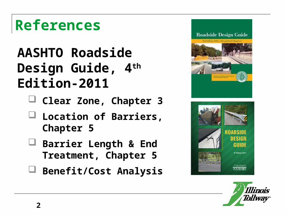
References
AASHTO Roadside Design Guide, 4th Edition-2011
Clear Zone, Chapter 3 Location of Barriers, Chapter 5 Barrier Length & End Treatment,
Chapter 5 Benefit/Cost Analysis
2
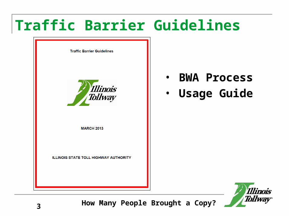
Traffic Barrier Guidelines
How Many People Brought a Copy?3
• BWA Process• Usage Guide
Barrier Warrant Analysis Procedure
Traffic Barrier GuidelinesSection 4.0
4
Barrier Warrant Analysis Procedure1. Identify Potential Obstacles2. Name Obstacles3. Prepare/Present Exhibit (Concept Meeting)
5
Barrier Warrant Analysis Procedure1. Identify Potential Obstacles.2. Name Obstacles.3. Prepare/Present Exhibit.4. Each AOC shall be analyzed separately.
a. Establish EOTW
6
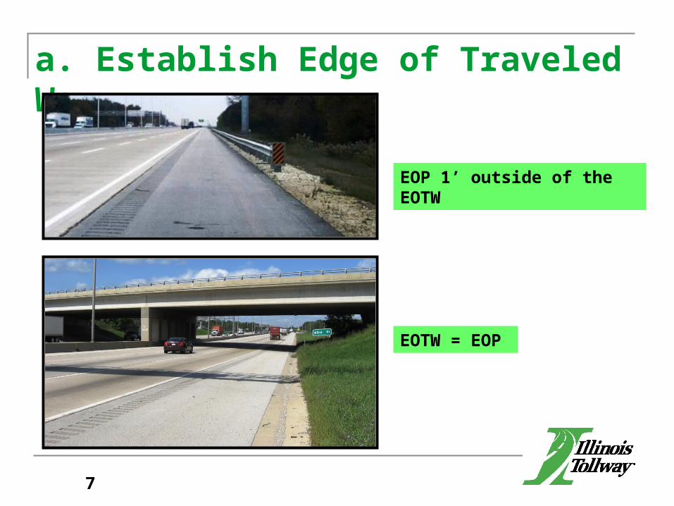
a. Establish Edge of Traveled Way
EOP 1’ outside of the EOTW
EOTW = EOP
7
Barrier Warrant Analysis Procedure1. Identify Potential Obstacles.2. Name Obstacles.3. Prepare/Present Exhibit.4. Each AOC shall be analyzed separately.
a. Establish EOTWb. Design Speed (Speed Profile for ramps, etc.)
8
Barrier Warrant Analysis Procedure1. Identify Potential Obstacles.2. Name Obstacles.3. Prepare/Present Exhibit.4. Each AOC shall be analyzed separately.
a. Establish EOTWb. Design Speedc. Design ADT
9
Barrier Warrant Analysis Procedure1. Identify Potential Obstacles.2. Name Obstacles.3. Prepare/Present Exhibit.4. Each AOC shall be analyzed separately.
a. Establish EOTWb. Design Speedc. Design ADTd. Length of Runout
10
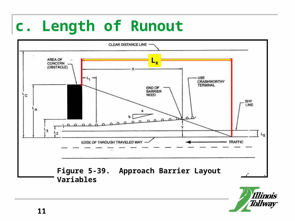
c. Length of Runout
L2
Figure 5-39. Approach Barrier Layout Variables
LR
11
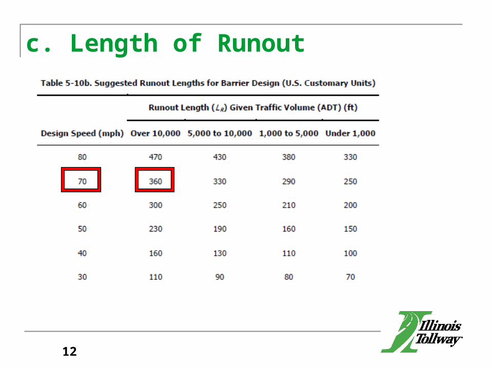
c. Length of Runout
12
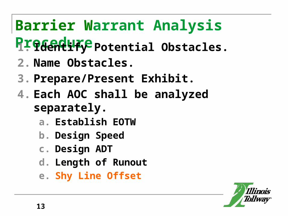
Barrier Warrant Analysis Procedure1. Identify Potential Obstacles.2. Name Obstacles.3. Prepare/Present Exhibit.4. Each AOC shall be analyzed separately.
a. Establish EOTWb. Design Speedc. Design ADTd. Length of Runoute. Shy Line Offset
13
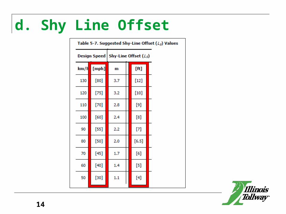
d. Shy Line Offset
14
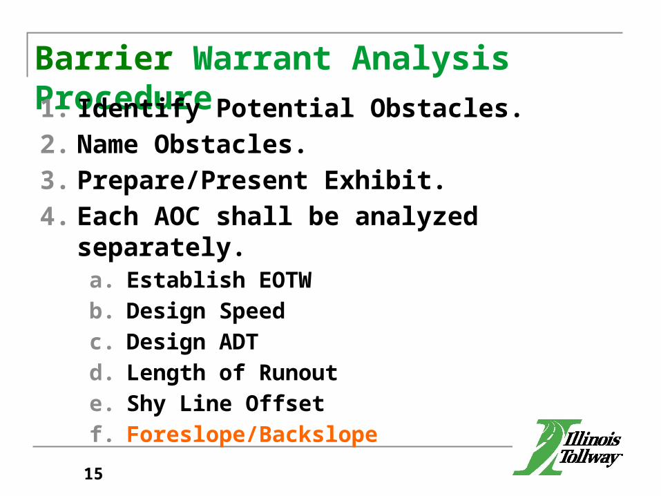
Barrier Warrant Analysis Procedure1. Identify Potential Obstacles.2. Name Obstacles.3. Prepare/Present Exhibit.4. Each AOC shall be analyzed separately.
a. Establish EOTWb. Design Speedc. Design ADTd. Length of Runoute. Shy Line Offsetf. Foreslope/Backslope
15
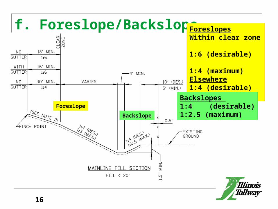
f. Foreslope/Backslope
Foreslope
Backslope
ForeslopesWithin clear zone 1:6 (desirable) 1:4 (maximum)Elsewhere1:4 (desirable)1:3 (maximum)
Backslopes 1:4 (desirable)1:2.5 (maximum)
16
Barrier Warrant Analysis Procedure (cont.)
g. Clear Zone
17
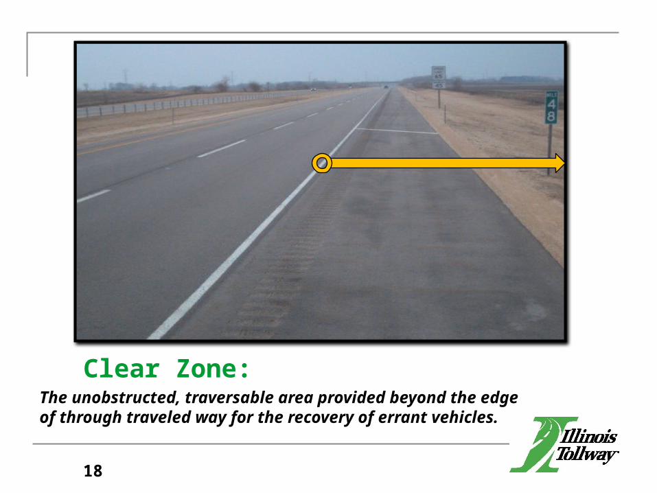
Clear Zone:The unobstructed, traversable area provided beyond the edge of through traveled way for the recovery of errant vehicles.
18
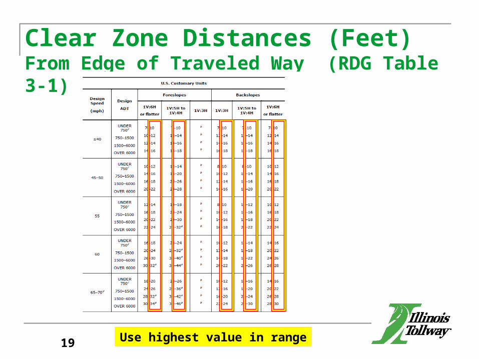
Clear Zone Distances (Feet) From Edge of Traveled Way (RDG Table 3-1)
Use highest value in range19
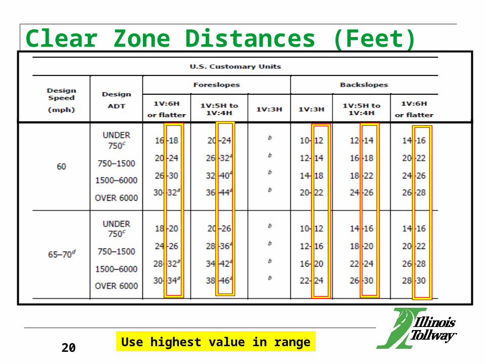
Clear Zone Distances (Feet) From Edge of Traveled Way (Table 3-1)
Use highest value in range20
Barrier Warrant Analysis Procedure (cont.)g. Clear Zoneh. Clear Zone Adjustment
21
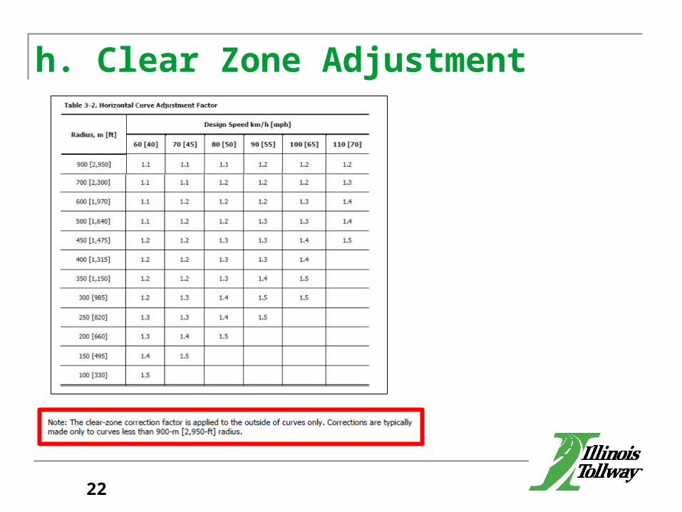
h. Clear Zone Adjustment
22

Barrier Warrant Analysis Procedure (cont.)g. Clear Zoneh. Clear Zone Adjustmenti. Lateral Extent of the Area of Concern (LA)
23
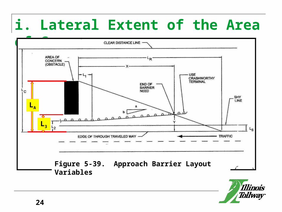
i. Lateral Extent of the Area of Concern
L2
Figure 5-39. Approach Barrier Layout Variables
LA
L3
24
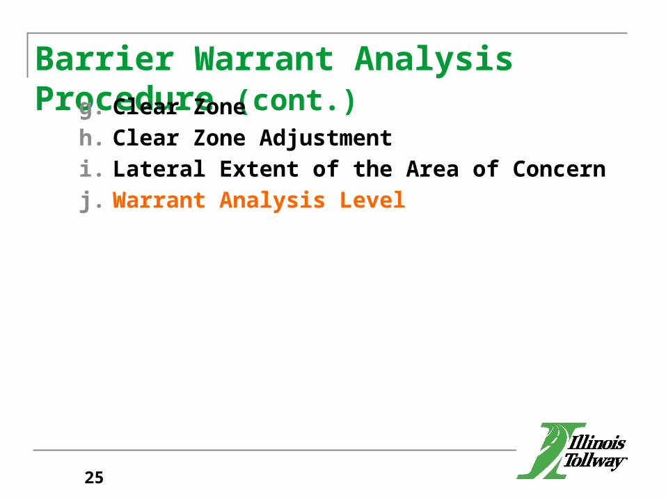
Barrier Warrant Analysis Procedure (cont.)g. Clear Zoneh. Clear Zone Adjustmenti. Lateral Extent of the Area of Concernj. Warrant Analysis Level
25
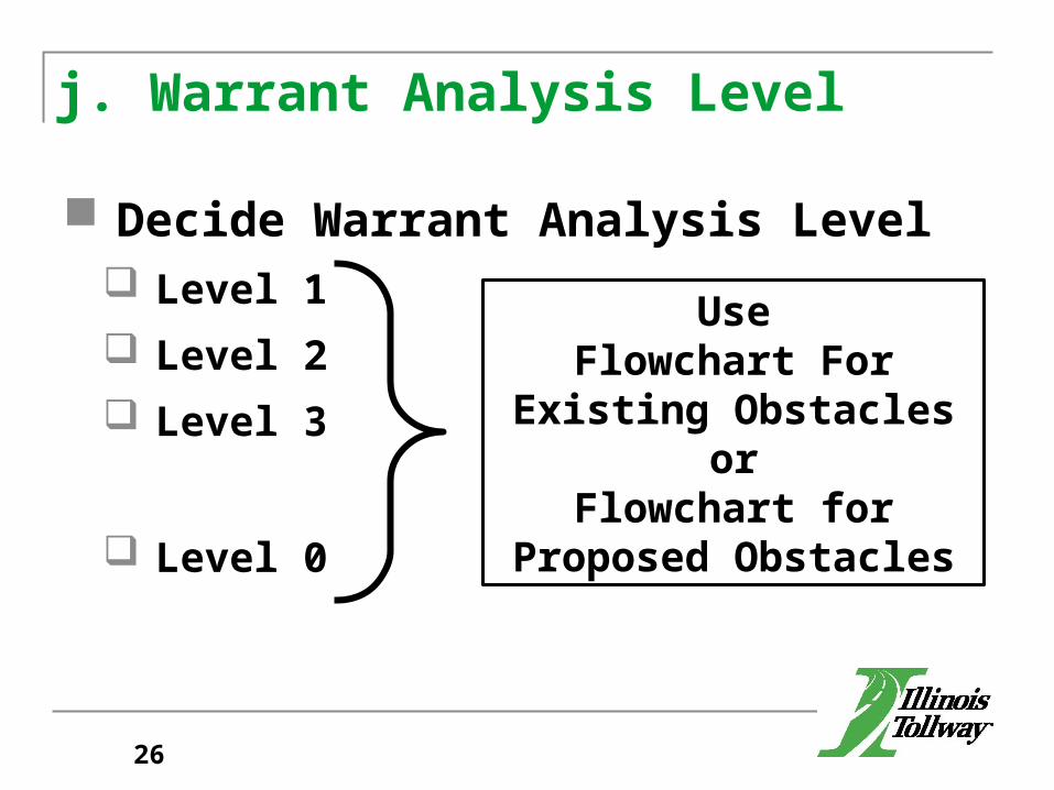
j. Warrant Analysis Level
Decide Warrant Analysis Level Level 1 Level 2 Level 3
Level 0
UseFlowchart For Existing
Obstaclesor
Flowchart for Proposed Obstacles
26

Flowchart for Analysis of Existing Obstacles (Figure 5.5a)
27
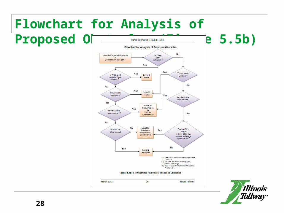
Flowchart for Analysis of Proposed Obstacles (Figure 5.5b)
28
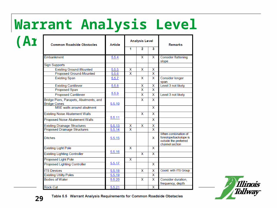
Warrant Analysis Level (Article 5.5)
29
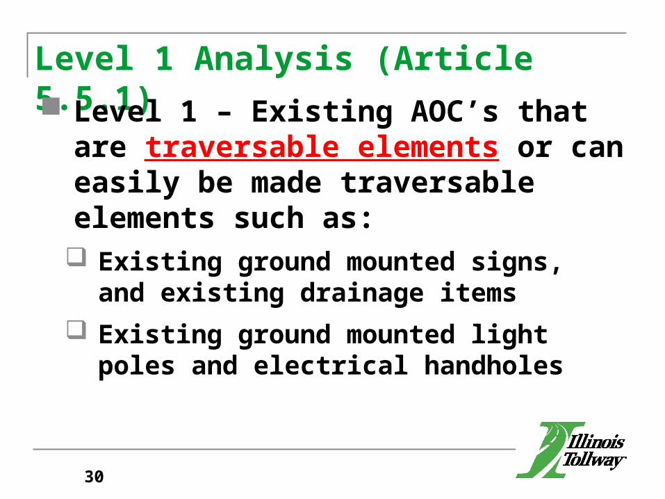
Level 1 Analysis (Article 5.5.1) Level 1 – Existing AOC’s that are traversable
elements or can easily be made traversable elements such as: Existing ground mounted signs, and existing
drainage items Existing ground mounted light poles and
electrical handholes
30
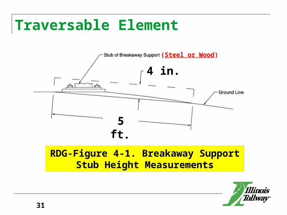
Traversable Element
RDG-Figure 4-1. Breakaway SupportStub Height Measurements
31
4 in.
5 ft.
(Steel or Wood)
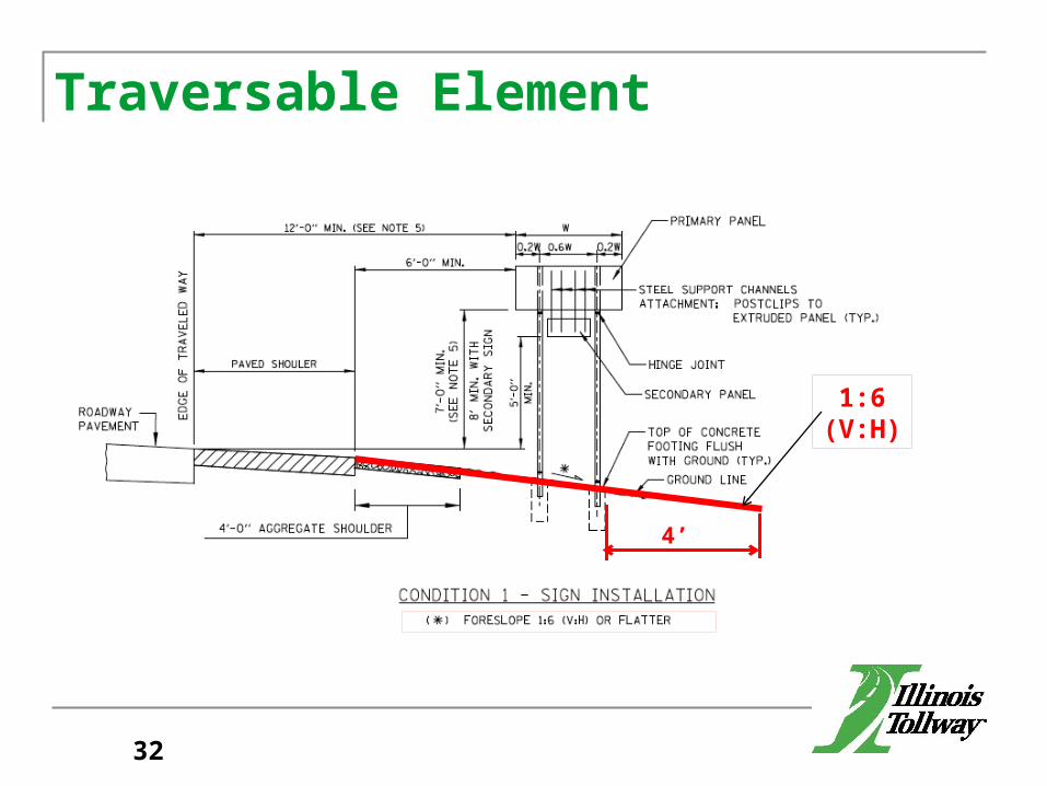
Traversable Element
4’
1:6(V:H)
32

Level 1 Analysis (Article 5.5.1) Level 1 – Proposed AOC’s that are
traversable elements: Proposed Ground-Mounted Signs Proposed Light Poles Proposed Drainage Items (culvert and pipe ends
84” or less in vertical opening)
33
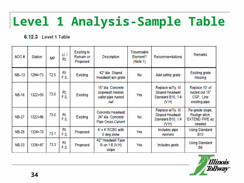
Level 1 Analysis-Sample Table
34
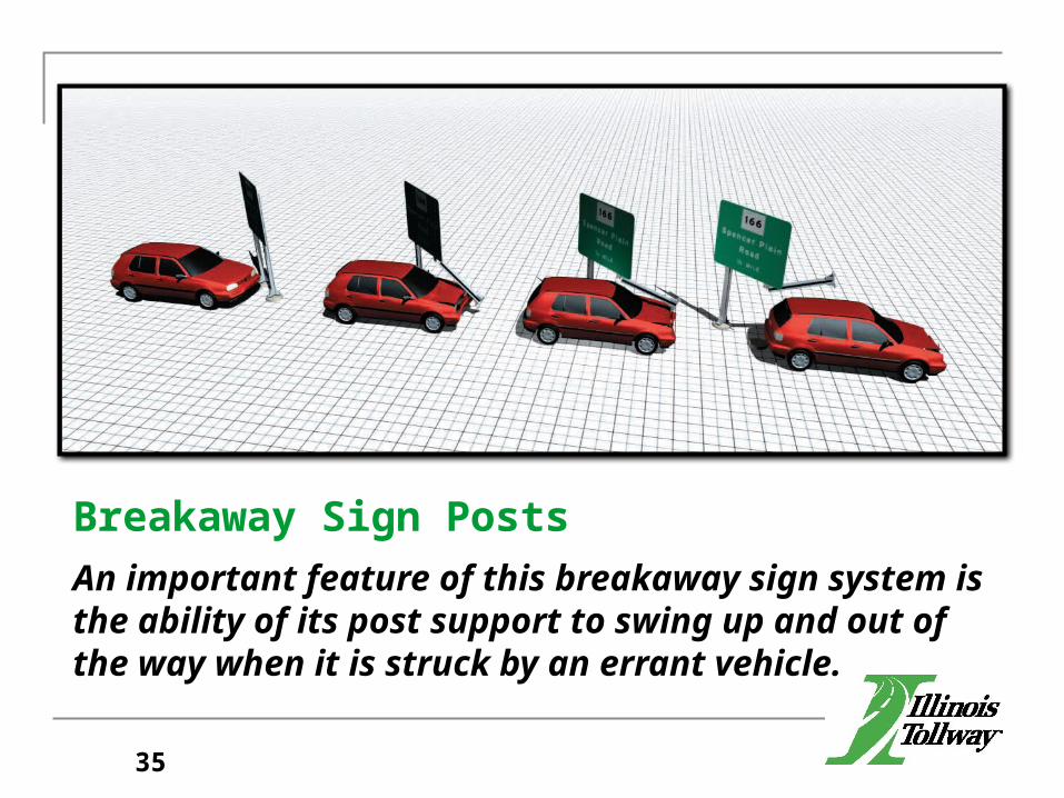
Breakaway Sign PostsAn important feature of this breakaway sign system is the ability of its post support to swing up and out of the way when it is struck by an errant vehicle.
35
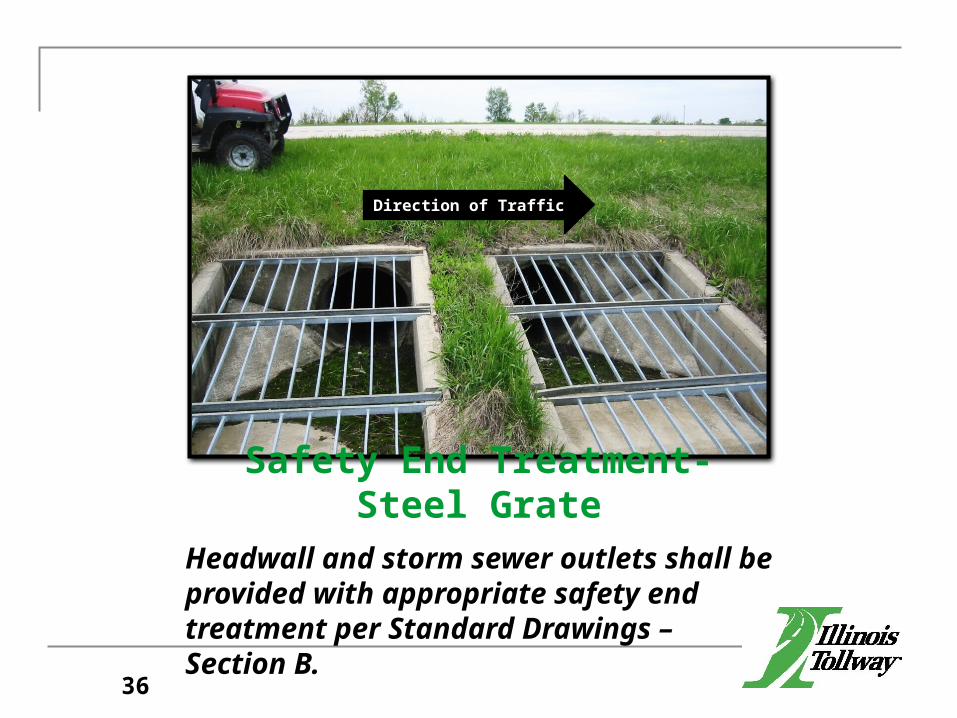
Safety End Treatment-Steel GrateHeadwall and storm sewer outlets shall be provided with appropriate safety end treatment per Standard Drawings – Section B.
Direction of Traffic
36
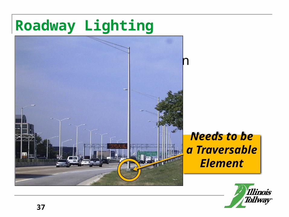
Roadway Lighting
Steel Helix Foundation
Needs to be a Traversable
Element
37
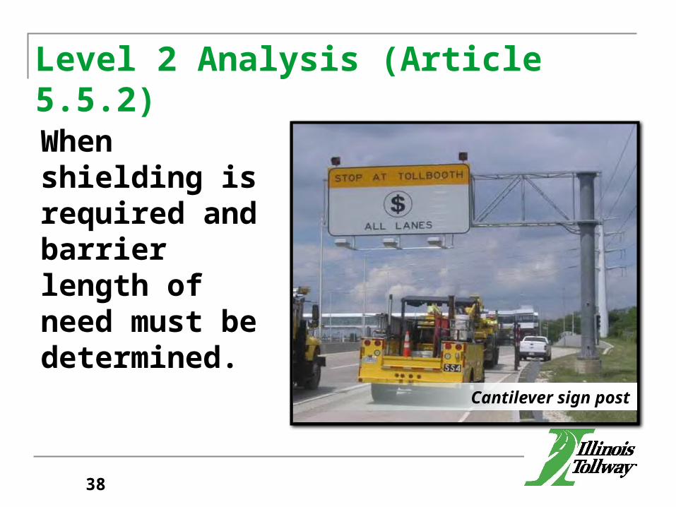
Level 2 Analysis (Article 5.5.2)
When shielding is required and barrier length of need must be determined.
Cantilever sign post
38
Shielding- Definition
Shielding—The introduction of a barrier or crash cushion between the vehicle and an obstacle or area of concern to reduce the severity of impacts of errant vehicles.
39
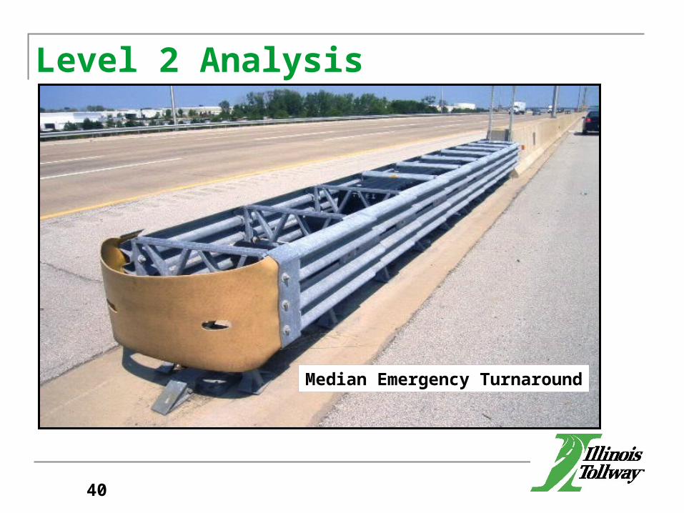
Level 2 Analysis
40
Median Emergency Turnaround
Level 2 Analysis (Article 5.5.2)
This analysis is performed for:
EXISTING/PROPOSED OBSTACLES when there are no feasible alternatives for eliminating, or reducing the impact severity of the obstacle.
PROPOSED OBSTACLES for an Alternative in a Level 3 Analysis. The length of barrier and type of terminals has to be determined for each Alternative that involves shielding of the obstacle.
41
Level 3 Analysis (Article 5.5.3)
The evaluation of two or more feasible alternatives for;
Removing Relocating Reducing the impact severity of Shielding the obstacle
This is part of the design process
42
Level 3 AnalysisDetermination of Alternatives (Article 5.6.1) If a Level 3 analysis is warranted, then the designer
needs to use engineering judgment when selecting the alternatives to evaluate.
Only consider alternatives that are feasible. Cannot analyze an alternative that leaves an
obstacle unshielded in the clear zone.
43
Level 3 Analysis (Article 5.6.1)
When considering relocation of a fixed object, in addition to changing the offset from the EOTW, the designer should consider relocation upstream or downstream.
Alternatives for sign truss span lengths or cantilever arm lengths shall not exceed the maximums shown on the Tollway Standard Drawings.
44
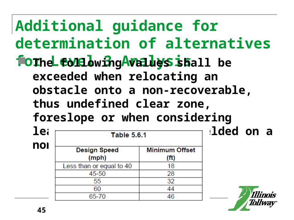
Additional guidance for determination of alternatives for Level 3 Analysis The following values shall be exceeded when
relocating an obstacle onto a non-recoverable, thus undefined clear zone, foreslope or when considering leaving an obstacle unshielded on a non-recoverable foreslope:
45
Roadside Safety Analysis Program (RSAP)
46
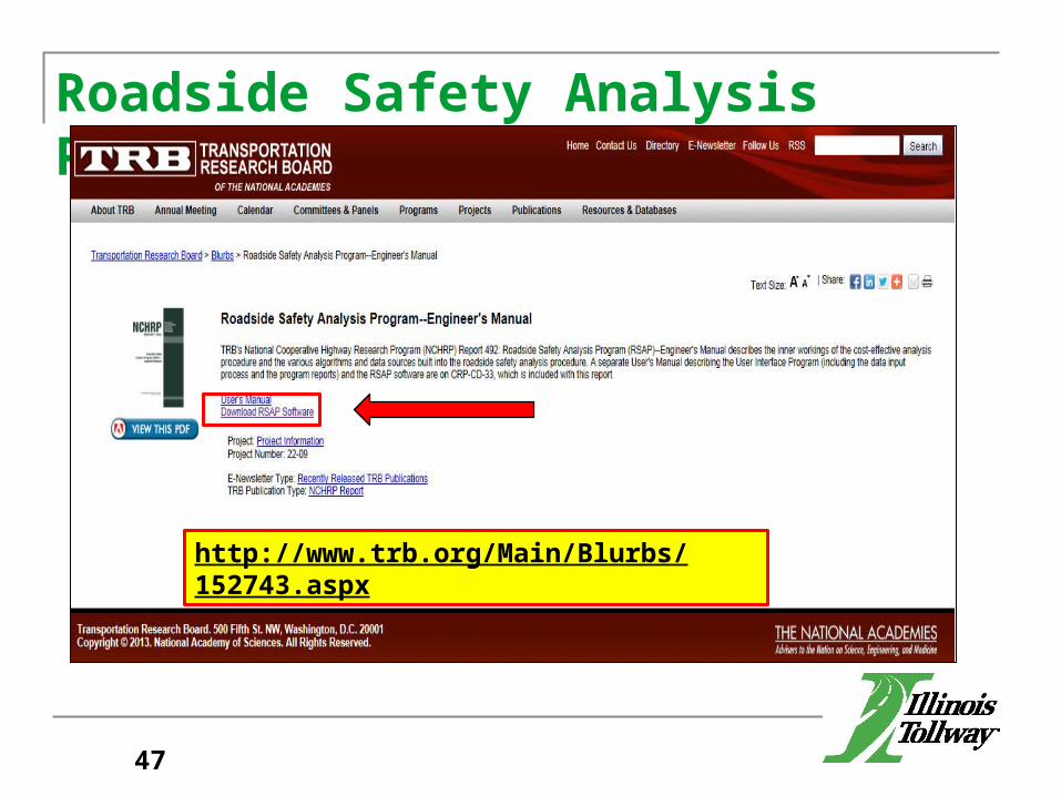
Roadside Safety Analysis Program (RSAP)
47
http://www.trb.org/Main/Blurbs/152743.aspx
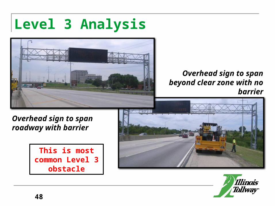
Level 3 Analysis
Overhead sign to span roadway with barrier
Overhead sign to span beyond clear zone with no barrier
This is most common Level 3
obstacle
48
Level 0 Table Requirements(Articles 5.5 and 6.13.8) Potential AOCs not analyzed with a Level 1, 2, or 3
Analysis shall be included in a Level 0 Table. This table should include all potential AOCs that
were initially identified in the process, but were determined to be well outside of the clear zone or existing obstacles physically removed from the project and, therefore required no analysis.
49
Barrier Warrant Analysis Procedure (cont.)g. Clear Zoneh. Clear Zone Adjustmenti. Lateral Extent of the Area of Concernj. Warrant Analysis Levelk. Lateral Offset of Barrier (L2)
50
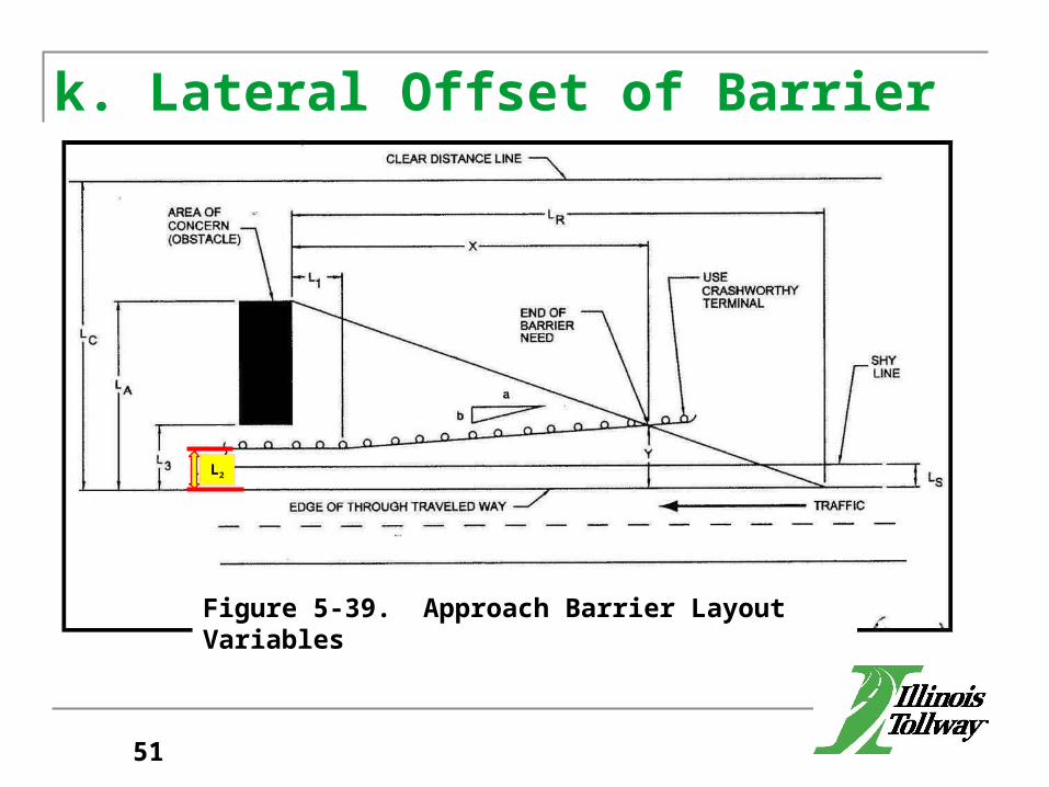
k. Lateral Offset of Barrier
L2
Figure 5-39. Approach Barrier Layout Variables
L2
51
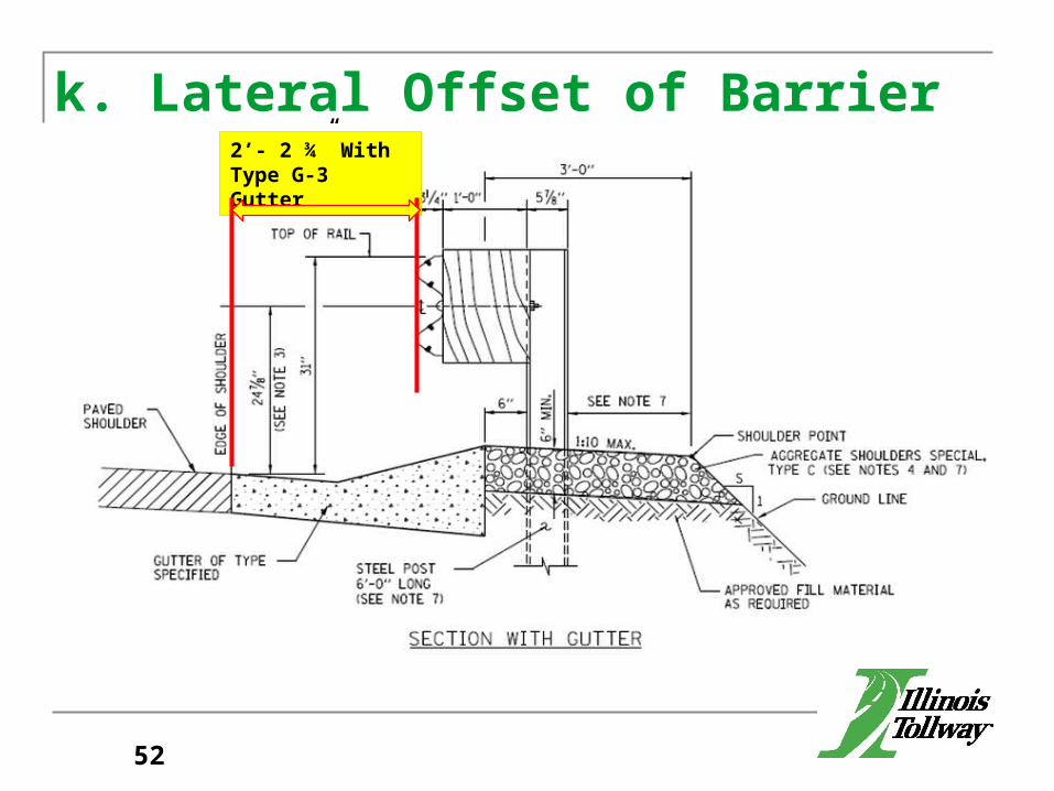
k. Lateral Offset of Barrier2’- 2 ¾” With Type G-3 Gutter
52
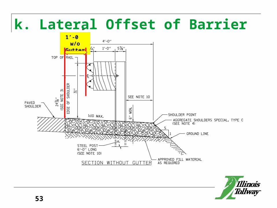
k. Lateral Offset of Barrier1’-0” w/o
Gutter
53
Barrier Warrant Analysis Procedure (cont.)g. Foreslope/Backslopeh. Clear Zonei. Clear Zone Adjustmentj. Warrant Analysis Levelk. Lateral Offset of Barrier l. Upstream End of Guardrail
54
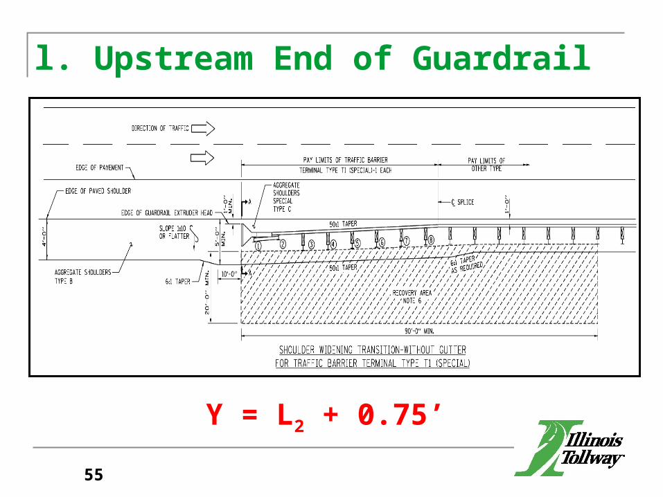
l. Upstream End of Guardrail
Y = L2 + 0.75’
55
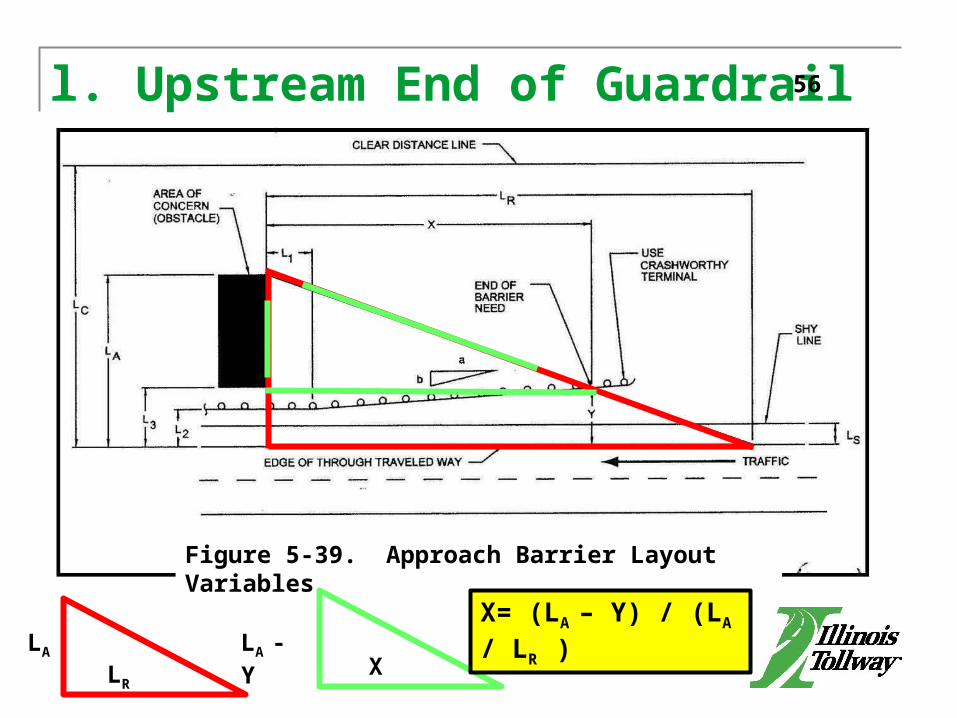
l. Upstream End of Guardrail
L2
Figure 5-39. Approach Barrier Layout Variables
X= (LA – Y) / (LA / LR )LA
LR
LA - Y X
56
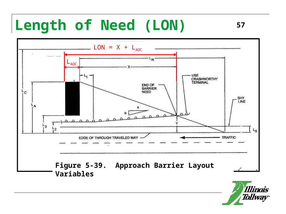
Length of Need (LON)
L2
Figure 5-39. Approach Barrier Layout Variables
57
LON = X + LAOC
LAOC
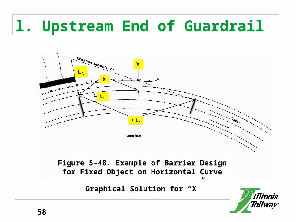
l. Upstream End of Guardrail
< LR
LA
L2
Y
X
Figure 5-48. Example of Barrier Design for Fixed Object on Horizontal Curve
Graphical Solution for “X”
58

l. Upstream End of Guardrail
L2
Figure 5-39. Approach Barrier Layout Variables
Point of Need
59
Barrier Warrant Analysis Procedure (cont.)g. Clear Zoneh. Clear Zone Adjustmenti. Lateral Extent of the Area of Concernj. Warrant Analysis Levelk. Lateral Offset of Barrierl. Upstream End of Guardrailm. Upstream End of Barrier Wall
60

m. Upstream End of Barrier Wall
A = Suggested maximum flare rate for rigid barrier system.
B = Suggested maximum flare rate for semi-rigid barrier system.
61
Barrier Warrant Analysis Procedure (cont.)g. Clear Zoneh. Clear Zone Adjustmenti. Lateral Extent of the Area of Concernj. Warrant Analysis Levelk. Lateral Offset of Barrierl. Upstream End of Guardrailm. Upstream End of Barrier Walln. Downstream Terminal
62
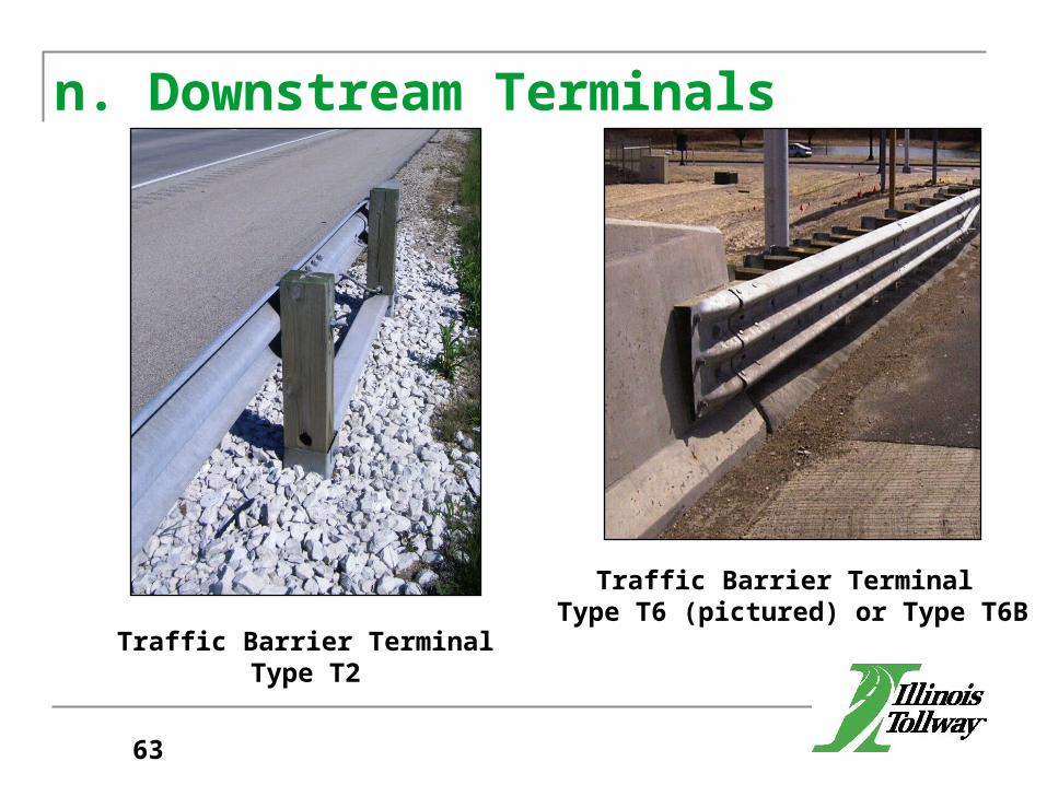
n. Downstream Terminals
Traffic Barrier Terminal Type T2
Traffic Barrier Terminal Type T6 (pictured) or Type T6B
63
Barrier Warrant Analysis Procedure (cont.)g. Clear Zoneh. Clear Zone Adjustmenti. Lateral Extent of the Area of Concernj. Warrant Analysis Levelk. Lateral Offset of Barrierl. Upstream End of Guardrailm. Upstream End of Barrier Walln. Downstream Terminalo. Barrier Obstacle
64

Barrier Warrant Analysis Procedure (cont.)g. Clear Zoneh. Clear Zone Adjustmenti. Lateral Extent of the Area of Concernj. Warrant Analysis Levelk. Lateral Offset of Barrierl. Upstream End of Guardrailm. Upstream End of Barrier Walln. Downstream Terminalo. Barrier Obstaclep. Compare existing length to proposed
65
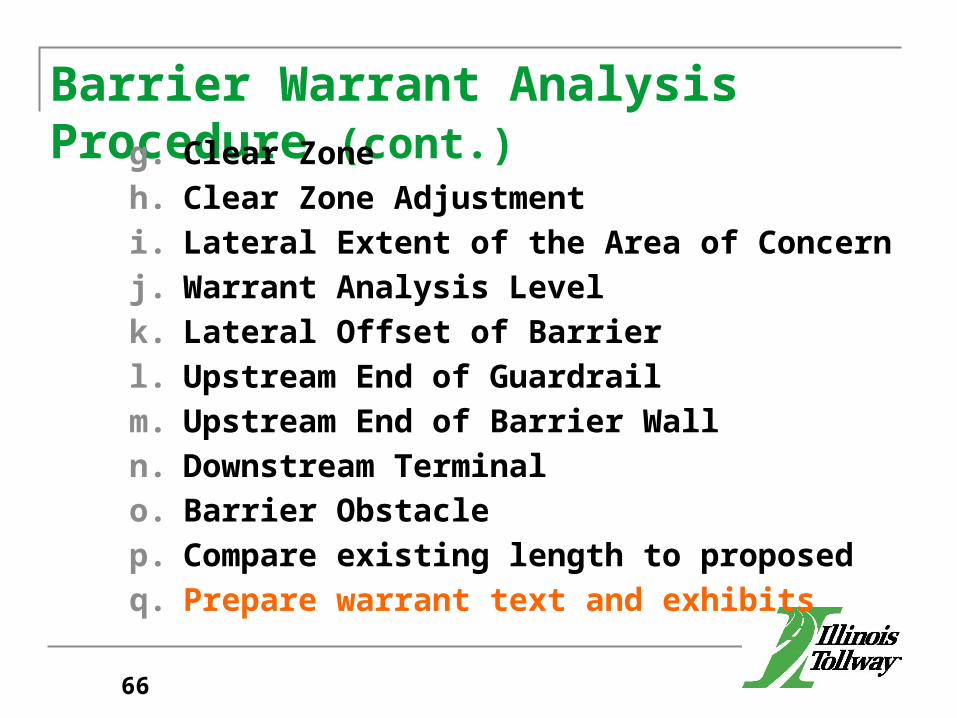
Barrier Warrant Analysis Procedure (cont.)g. Clear Zoneh. Clear Zone Adjustmenti. Lateral Extent of the Area of Concernj. Warrant Analysis Levelk. Lateral Offset of Barrierl. Upstream End of Guardrailm. Upstream End of Barrier Walln. Downstream Terminalo. Barrier Obstaclep. Compare existing length to proposedq. Prepare warrant text and exhibits
66
Presentation of BarrierWarrant Analysis
Section 6.0
67
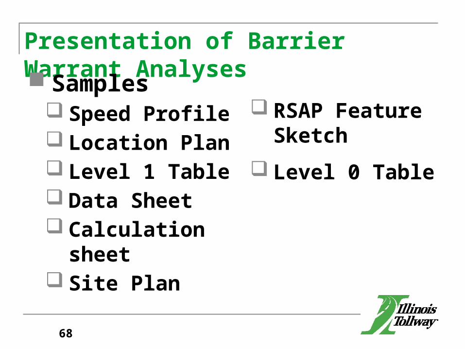
Presentation of Barrier Warrant Analyses
Samples Speed Profile Location Plan Level 1 Table Data Sheet Calculation sheet Site Plan
RSAP Feature Sketch
Level 0 Table
68

Presentation of Barrier Warrant Analysis Checklists
Cover Sheet Table of Contents Disposition Location Plan Data Sheet Calculation Sheet Site Plan
Summary Site Plan Cross Sections Level 0 Table Level 1 Analysis Level 2 Analysis Level 3 Analysis
69
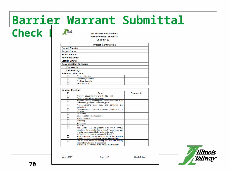
Barrier Warrant Submittal Check List
70

Highlights of the Process
Each AOC analyzed separately If several AOC’s are in close proximity, then
look for overlapping LON’s and gaps. Create Summary Site Plan Create AOC Table Calculations for overlaps / gaps (As Necessary)
71
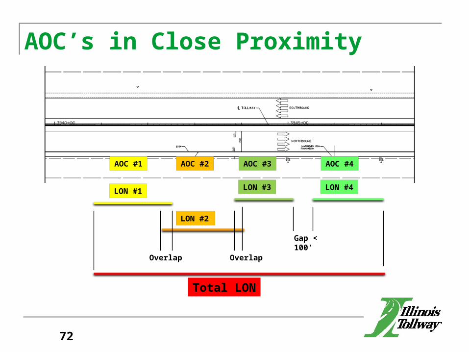
AOC’s in Close Proximity
AOC #1 AOC #2 AOC #3 AOC #4
LON #1
LON #2
LON #3 LON #4
Overlap Overlap
Gap < 100’
Total LON
72
Hot List-Common Mistakes Lack of DSE QC/QA Barrier Warrant Analysis is a Stand Alone
Document (Include Applicable Drawings) Site Plans Missing Information
Traffic Barrier Terminals Guardrail (By Type & Post Length) Recovery Area Label all Obstacles
73
Common Mistakes (continued) Checklist needs to be submitted and complete Disposition of Comments & Comment Resolution Drainage structures placed within the limits of
traffic barrier terminals Including items in the Level 1 table that are not
Level 1 items Not addressing the barrier clearance distance Intermixing Traffic Barrier Terminal (TBT) Type T6
and TBT Type T6B
74
Common Mistakes (continued) Not replacing gutter on rehabilitation contracts
when relocating Traffic Barrier Terminals Calculation of Length of Need on the outside of
horizontal curves (Graphical Solution required) Determination of Feasible Alternatives Locating the beginning and ending of slope
obstacles Evaluating potential obstacles along ramps, C-D
roads, or auxiliary lanes
75
Common Mistakes (continued) Analysis of closely spaced or overlapping potential
obstacles Preparation of speed profiles Minimum Length of free standing guardrail Identification of all potential obstacles Cross sections for LAOC & LR
Repeating information in the BWA
76
Submittal Schedule (Section 7.0)
Barrier Warrant Analysis is part of the Design Process.
Barrier Warrants are not considered final until there are no further review comments on the final submittal. (Article 7.6)
77
Concept Meeting (Article 7.1)The general goals of the meeting are to:
Provide an overview of the project limits, scope of work, and any omissions
Summarize the overall project schedule Discuss potential AOC’s and barrier warrant
analysis methodology Present unique project issues Identify locations that are good candidates to be
included in the preliminary submittal.
78
Concept Meeting (cont.) ID potential obstacles before clear zone is determined.
DSE to prepare an exhibit and present potential obstacles at a meeting to be held 1-2 weeks before Concept Plan submittal.
Aerial or TOPO background exhibit showing all potential obstacles.
Concept Plan submittal should only include the Meeting Minutes.
79
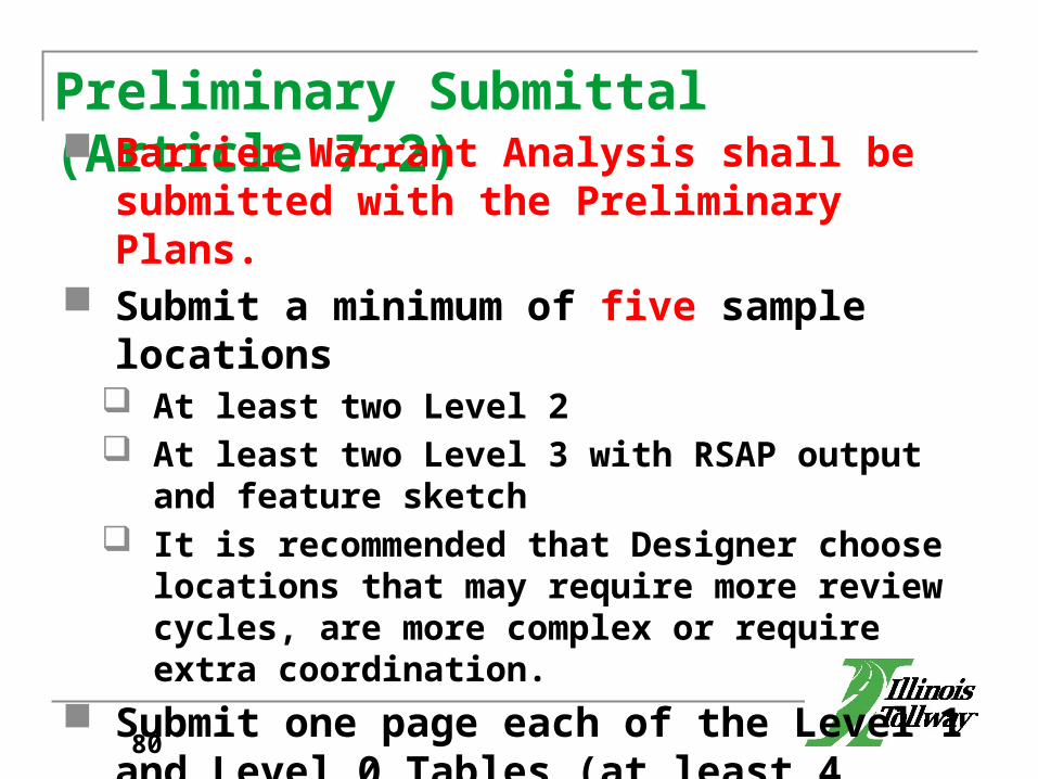
Preliminary Submittal (Article 7.2) Barrier Warrant Analysis shall be submitted with
the Preliminary Plans. Submit a minimum of five sample locations
At least two Level 2 At least two Level 3 with RSAP output and feature sketch It is recommended that Designer choose locations that
may require more review cycles, are more complex or require extra coordination.
Submit one page each of the Level 1 and Level 0 Tables (at least 4 AOC’s each)
Submit Completed Checklist.
80

Pre-Final Submittal (Article 7.3) Barrier Warrant Analysis shall be submitted with
the Pre-Final Plans. Similar to Pre-Final Plans, the Pre-Final Barrier
Warrant shall be considered 100% complete. All comments on preliminary submittal addressed
and a disposition provided. Submit completed checklist. All above materials shall be submitted through the
Tollway’s web-based project management system and in hard copy format.
81
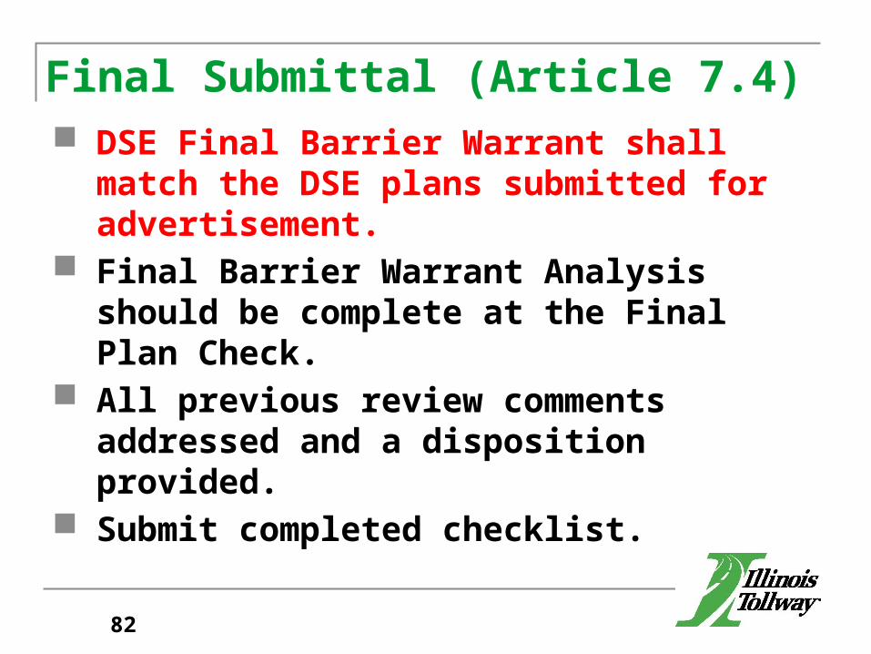
Final Submittal (Article 7.4) DSE Final Barrier Warrant shall match the DSE
plans submitted for advertisement. Final Barrier Warrant Analysis should be complete
at the Final Plan Check. All previous review comments addressed and a
disposition provided. Submit completed checklist.
82
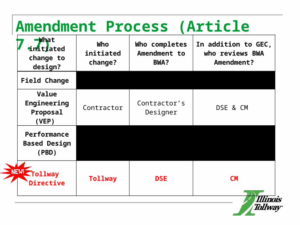
Amendment Process (Article 7.7)What initiated
change to design?
Who initiated change?
Who completes Amendment to
BWA?
In addition to GEC, who reviews BWA Amendment?
Field Change CM or Contractor DSE CM
Value Engineering
Proposal (VEP) Contractor Contractor’s
Designer DSE & CM
Performance Based Design
(PBD)Contractor Contractor’s
Designer DSE & CM
Tollway Directive Tollway DSE CM
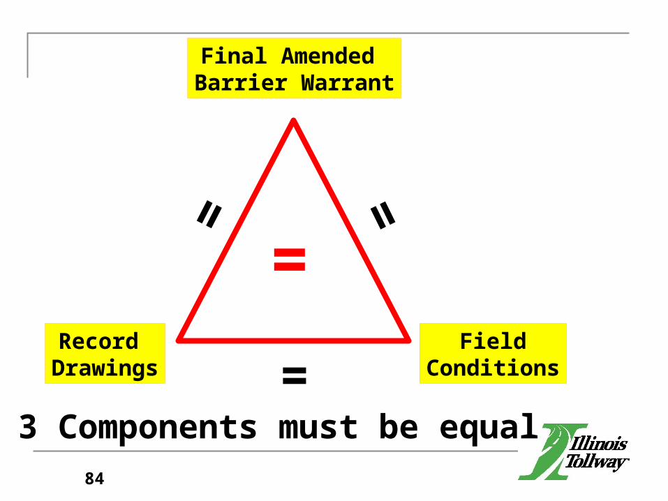
Record Drawings
FieldConditions
Final Amended Barrier Warrant
3 Components must be equal
==
=
=
84

Questions?
85
LUNCH HOUR
86