TRADOC Executive Agency Battle Damage Assessment …cdn.asktop.net/wp/download/GTA01-14-001.pdf ·...
20
TRADOC Executive Agency Battle Damage Assessment and Repair/Recovery 5046 Havre de Grace Street Aberdeen Proving Ground, Maryland 21005 410-278-3050/3488 DSN: 298-3050 [email protected] MARCH 2007
Transcript of TRADOC Executive Agency Battle Damage Assessment …cdn.asktop.net/wp/download/GTA01-14-001.pdf ·...

TRADOC Executive Agency Battle Damage Assessment and Repair/Recovery
5046 Havre de Grace Street Aberdeen Proving Ground, Maryland 21005
410-278-3050/3488
DSN: 298-3050
MARCH 2007
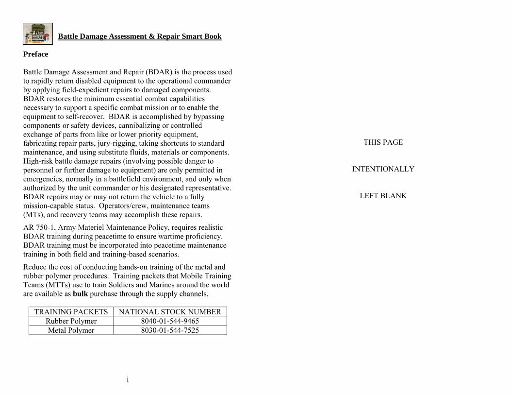
Battle Damage Assessment & Repair Smart Book
i
Preface Battle Damage Assessment and Repair (BDAR) is the process used to rapidly return disabled equipment to the operational commander by applying field-expedient repairs to damaged components. BDAR restores the minimum essential combat capabilities necessary to support a specific combat mission or to enable the equipment to self-recover. BDAR is accomplished by bypassing components or safety devices, cannibalizing or controlled exchange of parts from like or lower priority equipment, fabricating repair parts, jury-rigging, taking shortcuts to standard maintenance, and using substitute fluids, materials or components. High-risk battle damage repairs (involving possible danger to personnel or further damage to equipment) are only permitted in emergencies, normally in a battlefield environment, and only when authorized by the unit commander or his designated representative. BDAR repairs may or may not return the vehicle to a fully mission-capable status. Operators/crew, maintenance teams (MTs), and recovery teams may accomplish these repairs.
AR 750-1, Army Materiel Maintenance Policy, requires realistic BDAR training during peacetime to ensure wartime proficiency. BDAR training must be incorporated into peacetime maintenance training in both field and training-based scenarios.
Reduce the cost of conducting hands-on training of the metal and rubber polymer procedures. Training packets that Mobile Training Teams (MTTs) use to train Soldiers and Marines around the world are available as bulk purchase through the supply channels.
TRAINING PACKETS NATIONAL STOCK NUMBER Rubber Polymer 8040-01-544-9465 Metal Polymer 8030-01-544-7525
THIS PAGE
INTENTIONALLY
LEFT BLANK

Battle Damage Assessment & Repair Smart Book
R3
THIS PAGE
INTENTIONALLY
LEFT BLANK
Battle Damage Assessment & Repair Smart Book
ii
_____ NOTE
Upon completion of BDAR, notify maintenance personnel and the chain of command to initiate standard maintenance repairs.
_____ NOTE
Read entire procedures prior to each repair to prevent wasted resources and to ensure all required materials are available. Special attention must be given for cure times.
__________ WARNING
This manual contains nonstandard maintenance procedures. All normal safety procedures should be observed when the tactical situation permits. Extra care shall be taken when maintenance is required in a hostile environment.
__________ WARNING
Prior to making electrical repairs, disconnect the batteries to prevent electrical shock.
__________ WARNING
Personal Protective Equipment (PPE) must be worn when utilizing some products from the Battle Damage Assessment and Repair kits.
__________ WARNING
Some procedures in this manual may expose personnel to extreme heat. Care should be taken to protect personnel by whatever means available.
Battle Damage Assessment & Repair Smart Book
Battle Damage Assessment & Repair Smart Book
iii
R2
__________ References (continued) WARNING • TM 9-2350-200-BD-1, BDAR for Tank, Combat, Full-Tracked: 105-MM
Gun, M1, 105-MM Gun, IPM1, and 120-MM Gun, M1A1, 11 September 1991
Read all Material Safety Data Sheets (MSDS) accompanying the BDAR kit prior to utilizing the products. • TM 9-2350-252-BD, BDAR for Bradley Fighting Vehicle (BFV), M2, M3,
M2A1, and M3A1, September 1990 __________ WARNING • TM 9-2350-274-BD, BDAR for M109/M110/M578 Vehicles, Howitzer,
Medium, Self-Propelled, Full-Tracked, 31 January 1984 • TM 9-2350-275-BD, BDAR for M113 Family, Carrier, Personnel, Self-
Propelled, Full-Tracked, 09 February 1984 Sanding, grinding, or burning CARC paint produces Carcinogens, which has been determined to cause cancer.
• TM 9-2350-276-BD, BDAR for Combat Vehicles, 10 February 1984 __________ • TM 9-2350-284-BD, BDAR for Bradley Fighting Vehicle, M2A2 and M3A2, January 1992 WARNING
• TM 9-2350-358-BD, BDAR for Howitzer, Medium, Self-Propelled: 155MM, M109A6, 25 March 1994 Repairing vehicles that have been contaminated by Depleted
Uranium (DU) penetrators or have damaged DU armor may lead to heavy metal poisoning and radiation poisoning.
• TM 9-6115-624-BD, BDAR for Generators, 28 September 1990 • TM 11-5800-215-BD, BDAR for Communications-Electronics Equipment,
01 December 1986 • TM 55-1520-228-BD, BDAR for Helicopter, Observation OH-58A & OH-
58C, 04 January 1991 • TM 55-1520-244-BD, BDAR for Helicopter, Attack, AH-1E, AH-1F, and
AH-1P, 26 November 1990

Battle Damage Assessment & Repair Smart Book
R1
References Army Regulations • AR 750-1, Army Material Maintenance Policy, 5 September 2006
Department of the Army Pamphlets • DA Pam 700-48, Handling Procedures for Equipment Contaminated with
Depleted Uranium or Radio Active Commodities, 21 September, 2002. • DA Pam 750-8, The Army Maintenance Management System (TAMMS)
Users Manual, 22 August 2005
Field Manuals • FM 4-30.31, Recovery and Battlefield Damage Assessment and Repair, 19
September 2006
Technical Bulletins • TB 9-1300-278, Guidelines for Safe Response to Handling, Storage, and
Transportation Accidents Involving Army Tank Munitions or Armor which Contain Depleted Uranium, 23 February 2001
Technical Manuals • TM 1-1520-238-BD, BDAR for Helicopter, Attack, AH-64A Apache, 15
March 1996 • TM 1-1520-240-BD, BDAR for Army CH-47D Helicopter,
15 April 1997 • TM 3-251-BD, BDAR for Chemical Defensive Materiel,
23 September 1987 • TM 5-3835-222-BD, BDAR for POL Equipment, 23 June 1989 • TM 9-1000-257-BD, BDAR for 105-MM Howitzer Series,
04 April 2003 • TM 9-1000-258-BD BDAR for 155-MM Howitzer Series,
06 January 1988 • TM 9-2320-356-BD BDAR for Tactical Wheeled Vehicles, December 1987
Battle Damage Assessment & Repair Smart Book
iv
Table of Contents 1. BATTLE DAMAGE ASSESSMENT 1 1.1 Identify Battle Damage Indicators ............................................................ 1 1.2 Identify the Basic Rules of BDA............................................................... 2 1.3 Survey Initial Vehicle Battle Damage....................................................... 3 1.4 Determine Recovery Requirements Based on Initial Battle Damage
Survey ....................................................................................................... 3 1.5 Perform Complete Systems Self Test (BIT/BITE).................................... 3 1.6 Verify Operational Readiness of Systems and Subsystems ...................... 4 1.7 Determine Status and Mission Capability of Vehicle ............................... 4 1.8 Perform Risk Assessment for BDR........................................................... 4 1.9 Prioritize Sequence of BDR ...................................................................... 5 1.10 Identify Required Assets for BDR ............................................................ 5 2. RUBBER POLYMER BDR PROCEDURES 6 2.1 Common Tasks Associated with Rubber Polymer BDR........................... 6 2.2 Rubber Polymer BDR ............................................................................... 6 3. METAL BDR PROCEDURES 9 3.1 Metal Polymer BDR.................................................................................. 9 3.1.1 Common Tasks Associated with Metal BDR............................................ 9 3.1.2 Repair Procedures Utilizing Metal Polymer.............................................. 9 3.2 Metal Stick BDR..................................................................................... 13 3.2.1 Common Tasks Associated with Metal Stick BDR ................................ 13 3.2.2 Repair Procedures Utilizing Metal Stick................................................. 13 4. TIRE PLUG BDR PROCEDURES 15 4.1 Common Tasks Associated with Tire Plug BDR.................................... 15 4.2 Repair Procedure Utilizing Tire Plug...................................................... 15 5. ELECTRICAL BDR PROCEDURES 19 5.1 Common Tasks Associated with Electrical BDR.................................... 19 5.2 Repair Procedures for Electrical Repairs ................................................ 19 6. V-BELT REPLACEMENT BDR PROCEDURES 21 6.1 Common Tasks Associated with V-Belt Replacement BDR .................. 21 6.2 Repair Procedures Utilizing V-belt ......................................................... 21 7. RADIATOR BDR PROCEDURES 24 7.1 Common Tasks Associated with Radiator BDR ..................................... 24 7.2 Procedures for Radiator Repair ............................................................... 24 APPENDIX A. Maintainer Kit and Contents Listing ...................................A-1 APPENDIX B. Crew Kit and Contents Listing............................................ B-1 References...................................................................................................... R-1
Battle Damage Assessment & Repair Smart Book
Battle Damage Assessment & Repair Smart Book
1
B-2
1. Battle Damage Assessment Battle Damage Assessment (BDA) is the necessary first step of BDAR and starts the moment a crewmember recognizes battle damage. The objective of BDAR is to perform those actions required to get a system quickly back into operation, without injury to personnel, or without causing further damage to the equipment. The assessment determines the extent of damage, to include which systems or subsystems and components were damaged, the level of repair, and the risk involved with making the repairs. The assessment will also include an estimate of personnel, time, and materials required to perform expedient repairs. If not handled correctly, resources will be wasted and opportunities to return to the fight will be missed.
19 CLAMP, HOSE 3 INCH EA. 2 4730-00-908-6292
20 CLAMP, HOSE 3/4 INCH EA. 2 4730-00-908-3194
21 WIRE CONNECTOR, GRAY HD 10 5940-00-185-6673
22 WIRE CONNECTOR, ORANGE HD 10 5940-00-665-9559
23 WIRE CONNECTOR, BLUE HD 10 5940-00-146-2844
24 WIRE CONNECTOR, YELLOW PG 10 5940-00-578-2281
25 REFILL PLUGS EA. 30 5180-01-542-8147
26 INSERTION TOOL EA. 1 5120-01-533-9881
27 SPIRAL PROBE TOOL EA. 1 5120-01-533-9880
28 LUBE EA. 1 5180-01-542-8145
29 BELTING, V, ADJ. LENGTH FT 1 3030-00-224-8358
30 METAL POLYMER KT 4 8030-01-519-8280
31 RUBBER ELASTOMER KT 4 8040-01-519-7680
32 CLEANING/DEGREASING AGENT PT 1 7930-01-518-8743
33 CONDITIONING AGENT CA 1 8040-01-519-8282
34 RELEASE AGENT CA 1 8040-01-519-7681
35 REINFORCEMENT TAPE EA. 1 8030-01-519-4422
36 METAL REPAIR STICK TUBE 2 8030-01-519-7679
37 SPATULAS EA. 1 5120-01-519-4732
38 PLASTIC SPREADER EA. 2 5120-01-519-4730
39 BATTERY CONNECTOR EA. 1 5940-00-549-6581
40 STATIC DISCHARGE WRIST GROUND EA. 1 5920-01-154-1039
41 GLOVES, LATEX, DISPOSABLE PG 5 6515-01-329-4843
42 RESPIRATOR, AIR FILTERING BX 5 4240-01-492-0177
43 HACK SAW EA. 1 5110-01-491-5760
44 HACK SAW BLADES EA. 10 5110-00-277-4588
45 MINI UTILITY KNIFE EA. 1 5110-01-428-5220
46 40 GRIT SAND PAPER SH 3 5350-00-246-0331
47 ENVIROMENTAL PLUGS 2" EA. 2 NSN not Avail
48 ENVIROMENTAL PLUGS 4" EA. 2 NSN not Avail
1.1 Identify Battle Damage Indicators One of the most important phases of BDA is crew awareness during the moments immediately after the vehicle is affected by battle damage. During these crucial moments, the crew should immediately look for battle damage indicators (BDI) before any system or the vehicle shuts down.
Identifying BDI is important because the systems affected, or the engine, may shut down immediately or shortly after the impact. Indications include:
Smoke - indicates that a particular area, wiring harness, or component of the vehicle was damaged and could lead to electrical shorts or a fire. Fire - indicates damage to previously mentioned areas of the vehicle and poses an additional threat of igniting leaking combustible fluids or ammunition. Loss of mobility – a sudden disruption of movement or change in direction indicating that wheels, tracks, axles, or power train components were damaged. Loss of systems – indicate a failure in steering, brakes, air pressure, cooling capability, communications, weapons, turret and gun drives, or power train. Unusual mechanical noises – indicate possible damage to the engine, transmission, gearboxes, axles, or driveline components. Continued operation may result in further damage to these assemblies due to loss of lubricants or wear caused by damaged parts. Fault warning lights and alarms – indicate affected systems are not available and could place the crew or vehicle in danger, or the possibility of a component or system becoming unavailable if immediate action to repair the fault does not occur.

Battle Damage Assessment & Repair Smart Book
B-1
APPENDIX B. Crew Kit and Contents Listing
KIT, BDAR, CREW - NSN: 5180-01-502-9504
NO. NOMENCLATURE U.I. QTY. NSN 1 BAG, TOOL EA. 1 N/A
2 COMPONENTS LIST LABEL EA. 1 N/A
3 BDAR TAGS EA. 5 DD Form 1577
4 CONTAINER, SMALL PARTS EA. 1 8115-00-099-4380
5 WIRE, NON-ELECTRICAL LB 1 9505-00-221-2650
6 WIRE, ELECTRICAL, 16 AWG FT 1 6145-01-099-8029
7 FIBER GLASS, REPAIR FT 1 8040-01-346-1339
8 LEAK PREVENTIVE, RADIATOR KT 3 6850-00-598-7311
9 SEALING COMPOUND, BLUE TU 1 8030-01-323-4503
10 SEALING COMPOUND, RED TU 1 8030-01-212-9622
11 WIRE BRUSH, SCRATCH EA. 1 7920-00-282-9246
12 CABLE TIES, NYLON, BLACK HD 20 5975-00-985-6630
13 TAPE, INSULATING ELECTRICAL RO 1 5970-00-788-4901
14 TAPE, ALUMINUM RO 1 7510-00-684-8803
15 CLOTH TAPE RO 1 5640-00-103-2254
16 ANTISEIZE TAPE EA. 1 8030-00-889-3535
17 CLAMP, HOSE 2 INCH EA. 2 4730-00-909-8627
18 CLAMP, HOSE 4 INCH EA. 2 4730-00-908-6293
Battle Damage Assessment & Repair Smart Book
2
Leaking fluids – indicate that a cell, component, fuel line, hydraulic line, radiator, or brake line has been damaged. Fumes can be a health hazard when inhaled, and a build up of fumes from combustible liquids can lead to an explosion. Unusual odors – give specific indications of what type of material might be burning or leaking. Fuels, coolant, and hydraulic fluids emit particular odors that will help identify which system is affected. Burning materials like rubber, paint, liquids, plastic insulation around wiring, and clothing also emit distinctive odors.
Being able to recognize and identify the various BDI will reduce diagnostic time and increase battle damage repair (BDR) accuracy.
1.2 Identify the Basic Rules of BDA The next important step following a BDI is to identify and follow the basic rules of BDA. First and foremost, think safety! Before attempting to perform any BDA procedures, be certain that the area in and around the vehicle is free from hazards that could cause further damage or injury to personnel.
Check for contamination if you suspect the battle area was contaminated by biological/chemical weapons or damaged munitions which contained these hazards. Adopt the appropriate level of protection, and decontaminate the vehicle and equipment as required. Request support from a chemical decontamination team if the level of contamination is excessive.
The same procedures apply to depleted uranium (DU) contamination. DU dust particles pose a serious health threat when inhaled, ingested, or absorbed through skin lesions. The use of a radiation meter is the prescribed method for determining the presence and level of DU contamination.
When dealing with abandoned vehicles, carefully check for booby traps around, under, and inside the vehicle. Also, be aware of loaded weapons, live ammunition, damaged weapons, wiring, leaking combustible fluids, and unexploded ordnance (UXO). Do not disturb any ordnance that appears unstable or armed. If any of these conditions involve UXO, contact Explosive Ordnance Disposal (EOD) personnel, and do not continue with BDA until the area is rendered safe.
Always conduct a thorough safety check of equipment and vehicles prior to performing any BDA. Failure to observe all safety procedures can lead to catastrophic consequences.

Battle Damage Assessment & Repair Smart Book
Battle Damage Assessment & Repair Smart Book
3
A-2
1.3 Survey Initial Vehicle Battle Damage The initial survey consists of visually assessing the extent of primary damage to the exterior and interior components of the vehicle. Some questions that must be asked during this process include:
a. Is the area secure allowing for a safe assessment of damage? b. Is communication established with higher headquarters? c. Does the damage prevent the vehicle from moving under its own
power? d. Can battle damage repair (BDR) procedures enable the vehicle to
self-recover?
After surveying primary damage, survey the secondary damage to the vehicle and systems.
21 CLAMP, HOSE 3/4 INCH EA. 2 4730-00-908-3194 22 WIRE CONNECTOR, GRAY HD 10 5940-00-185-6673 23 WIRE CONNECTOR, ORANGE HD 10 5940-00-665-9559 24 WIRE CONNECTOR, BLUE HD 10 5940-00-146-2844 25 WIRE CONNECTOR, YELLOW PG 10 5940-00-578-2281 26 REFILL PLUGS EA. 30 5180-01-542-8147 27 INSERTION TOOL EA. 1 5120-01-533-9881 28 SPIRAL PROBE TOOL EA. 1 5120-01-533-9880 29 LUBE EA. 1 5180-01-542-8145 30 BELTING, V, ADJUSTABLE LENGTH FT 1 3030-00-224-8358 31 METAL POLYMER KT 6 8030-01-519-8280 32 RUBBER ELASTOMER KT 6 8040-01-519-7680 33 METAL POLYMER II KIT 1 8030-01-519-8281 34 ClLEANING/DEGREASING AGENT PT 1 7930-01-518-8743 35 CONDITIONING AGENT CA 1 8040-01-519-8282 36 RELEASE AGENT CA 1 8040-01-519-7681 37 REINFORCEMENT TAPE EA. 1 8030-01-519-4422 38 METAL REPAIR STICK TU 2 8030-01-519-7679 39 SPATULA EA. 1 5120-01-519-4732 40 PLASTIC SPREADER EA. 2 5120-01-519-4730 41 BATTERY CONNECTOR EA. 1 5940-00-549-6581 42 STATIC DISCHARGE WRIST GROUND EA. 1 5920-01-154-1039 43 GLOVES, LATEX, DISPOSABLE PG 5 6515-01-329-4843 44 RESPIRATOR, AIR FILTERING BX 5 4240-01-492-0177 45 HACK SAW EA. 1 5110-01-491-5760 46 HACK SAW BLADES EA. 10 5110-00-277-4588 47 MINI UTILITY KNIFE EA. 1 5110-01-428-5220 48 40 GRIT SAND PAPER SH 3 5350-00-246-0331 49 ENVIROMENTAL PLUGS 2" EA. 2 NSN not Avail 50 ENVIROMENTAL PLUGS 4" EA. 2 NSN not Avail 51 HYDRAULIC/FUEL LINE FITTING 3/16 EA. 2 4730-00-289-1622 52 HYDRAULIC/FUEL LINE FITTING 1/4 EA. 2 4730-00-278-8717 53 HYDRAULIC/FUEL LINE FITTING 5/16 EA. 2 4730-00-278-3225 54 HYDRAULIC/FUEL LINE FITTING 3/8 EA. 2 4730-00-289-0782
1.4 Determine Recovery Requirements Based on Initial Battle Damage Survey
Based on the initial survey, determine if the vehicle is destroyed and should be recovered or left on site. Determine if the vehicle can self–recover or, if necessary, can be moved to a safer location using a same or heavier class vehicle. Recoverability status must be determined during the initial survey.
Non-Self-Recovery Capable – indicates that the vehicle cannot move under its own power but does not meet the criteria for cannibalization.
Depending on the weight classification of the disabled vehicle, dedicated recovery assets may be required to move it to the unit maintenance collection point (UMCP).
Self-Recovery Capable – indicates that the vehicle is capable of clearing the battlefield under its own power but is not mission capable. It may also be used to recover other damaged equipment not capable of self-recovery.
1.5 Perform Complete Systems Self Test (BIT/BITE) With primary damage assessment complete, determine the extent of secondary damage.
On vehicles with systems capable of performing a self test, perform a complete diagnostic check to identify which systems are operational. Only qualified personnel should operate the equipment. Improper procedures can cause injuries or further damage.

Battle Damage Assessment & Repair Smart Book
Battle Damage Assessment & Repair Smart Book
A-1
4
1.6 Verify Operational Readiness of Systems and Subsystems At the completion of the self test, perform a functional test of all systems that are operable. A system may be operational but not fully functional. Examples:
APPENDIX A. Maintainer Kit and Contents Listing
a. Test indicates that the turret/gun drive is functioning, but the turret
will not traverse 360º due to internal or external damage or an obstruction. b. Communication system is operational, but the frequency range is
limited. c. Steering system works but the vehicle cannot make sharp turns. 1.7 Determine Status and Mission Capability of Vehicle
Determining the status of the vehicle is very important. Combat vehicles must be able to shoot, move, and communicate. Battle damage can disable or degrade one or more systems, thus limiting the vehicle’s mission capability. There are two classification levels which describe the mission readiness of equipment.
KIT, BDAR, MAINTAINER - NSN: 5180-01-502-9507 NO. NOMENCLATURE U.I. QTY. NSN
1 BOX, TOOL EA. 1 N/A 2 COMPONENTS LIST LABEL EA. 1 N/A 3 BDAR TAGS EA. 5 DD Form 1577 4 CONTAINER, SMALL PARTS EA. 1 8115-00-099-4380 5 WIRE, NON-ELECTRICAL LB 1 9505-00-221-2650 6 WIRE, ELECTRICAL, 16 AWG FT 1 6145-01-099-8029 7 WIRE, ELECTRICAL, 22 AWG FT 1 6145-01-245-8855 8 FIBER GLASS, REPAIR KT 1 8040-01-346-1339 9 LEAK PREVENTIVE COMPOUND,
RADIATOR BX 3 6850-00-598-7311
10 SEALING COMPOUND, BLUE TU 1 8030-01-323-4503 11 SEALING COMPOUND, RED TU 1 8030-01-212-9622 12 WIRE BRUSH, SCRATCH EA. 1 7920-00-282-9246 13 CABLE TIES, NYLON, BLACK HD 20 5975-00-985-6630 14 TAPE, INSULATING ELECTRICAL RO 1 5970-00-788-4901 15 TAPE, ALUMINUM RO 1 7510-00-684-8803 16 CLOTH TAPE RO 1 5640-00-103-2254 17 ANTISEIZE TAPE EA. 1 8030-00-889-3535 18 CLAMP, HOSE 2 INCH EA. 2 4730-00-909-8627 19 CLAMP, HOSE 4 INCH EA. 2 4730-00-908-6293 20 CLAMP, HOSE 3 INCH EA. 2 4730-00-908-6292
a. Combat Emergency Capable – indicates the vehicle meets the criteria for a specific mission, but not all systems (shoot, move, communicate) are fully functional.
b. Fully mission capable – indicates the equipment is functioning as designed and has no faults from the –10 manual in the “equipment is not ready/available if” column of the operator’s PMCS.
1.8 Perform Risk Assessment for BDR After identifying which systems or subsystems are not operational, determine the risk level for each repair. Repairs can be classified in one of three different risk levels:
High Risk Repair - This type of BDR may result in injury to personnel or cause further damage to the equipment. Example: Using a fuse or circuit breaker of higher amperage rating can cause circuit overloads and fires.
Medium Risk Repair - This type of BDR may result in further damage to equipment. Example: An engine with low coolant level may overheat causing the engine to lock-up.
Low Risk Repairs - This type of BDR may result in minor equipment failures but poses little or no threat to personnel. Example: Using a fuse or circuit breaker of lower amperage rating can cause equipment systems to frequently shut down.
Battle Damage Assessment & Repair Smart Book
Battle Damage Assessment & Repair Smart Book
5
26
1.9 Prioritize Sequence of BDR During the BDA process, it is important to perform an “equipment triage.” Triage is a process used to determine the sequence of repairs to battle damaged equipment based on Mission, Enemy, Terrain and weather, Troops and support available-Time available and Civil considerations (METT-TC).
The battlefield is a chaotic environment with many unexpected circumstances. Specific repair procedures may not be listed in technical or field manuals, and repair parts, tools, and skilled personnel may not be available. Flexibility and ingenuity are crucial to successful performance of BDAR.
After performing triage, repair only what is needed. Spending time on non-essential repairs is a waste of resources. The main objective of BDAR is to perform those actions required to get a system back into operation quickly, without injury to personnel, or without causing further damage to the equipment.
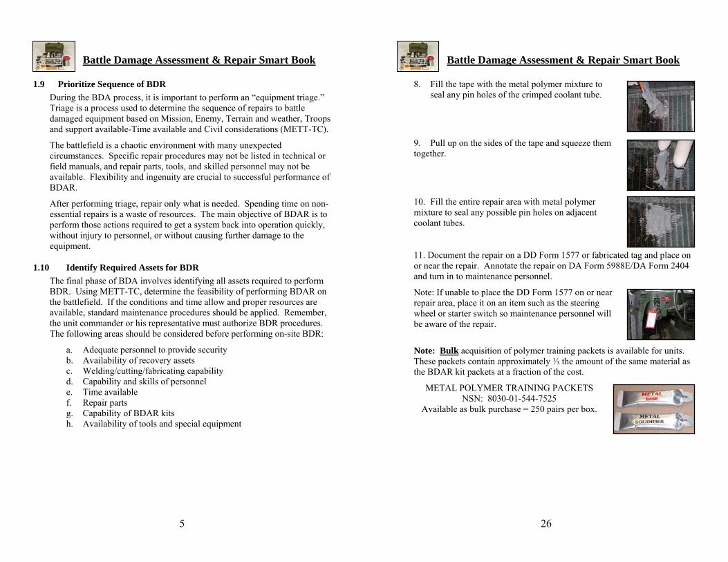
8. Fill the tape with the metal polymer mixture to seal any pin holes of the crimped coolant tube.
1.10 Identify Required Assets for BDR The final phase of BDA involves identifying all assets required to perform BDR. Using METT-TC, determine the feasibility of performing BDAR on the battlefield. If the conditions and time allow and proper resources are available, standard maintenance procedures should be applied. Remember, the unit commander or his representative must authorize BDR procedures. The following areas should be considered before performing on-site BDR:
a. Adequate personnel to provide security b. Availability of recovery assets c. Welding/cutting/fabricating capability d. Capability and skills of personnel e. Time available f. Repair parts g. Capability of BDAR kits h. Availability of tools and special equipment
9. Pull up on the sides of the tape and squeeze them together.
10. Fill the entire repair area with metal polymer mixture to seal any possible pin holes on adjacent coolant tubes.
11. Document the repair on a DD Form 1577 or fabricated tag and place on or near the repair. Annotate the repair on DA Form 5988E/DA Form 2404 and turn in to maintenance personnel.
Note: If unable to place the DD Form 1577 on or near repair area, place it on an item such as the steering wheel or starter switch so maintenance personnel will be aware of the repair.
Note: Bulk acquisition of polymer training packets is available for units. These packets contain approximately ⅓ the amount of the same material as the BDAR kit packets at a fraction of the cost.
METAL POLYMER TRAINING PACKETS NSN: 8030-01-544-7525
Available as bulk purchase = 250 pairs per box.

Battle Damage Assessment & Repair Smart Book
Battle Damage Assessment & Repair Smart Book
25
6
2. Rubber Polymer BDR Procedures 3. Squeeze the ends of severed coolant tube flat and fold over on each other approximately ½”.
4. Insert a small strip of aluminum tape under both folded ends of the coolant tube. Spread the sides of tape open to create a reservoir to receive the metal polymer mixture.
5. Cut off one end of both the base and solidifier packets as close as possible to the seal.
6. Using the straight edge of the mixing spatula or other suitable mixing tool, squeeze out the entire contents of the packets onto a working surface.
2.1 Common Tasks Associated with Rubber Polymer BDR a) Repair damaged tire sidewall (Only when damage is three inches or less.) b) Repair damaged radiator hoses c) Repair damaged rubber oil line d) Repair damaged rubber fuel lines e) Repair damaged hydraulic hose f) Repair damaged battery casing g) Repair damaged power steering hose
2.2 Rubber Polymer BDR Required Materials:
• Elastomer polymer packets • Mixing spatula/spreader • Wire brush • 40-grit sandpaper • Conditioning agent • Latex gloves • Dust mask
• Cleaning/degreasing agent • Reinforcement tape
7. Mix the two components thoroughly to achieve a uniform mixture free of any streakiness.
• DD Form 1577 • Mini utility knife • Goggles (not in kit) • Rag (not in kit)
Procedural Steps: Note: Be prepared to apply the metal polymer mixture quickly to the damaged area. The working times for the product are as follows: 1. Identify the damage.
Temperature 41° F
(5° C)
59° F
(15° C)
77° F
(25° C)
Use all material within 5 min 4 min 3 min 2. Remove all dirt, mud, and other contaminants from the damaged area. 3. Roughen the damaged area and approximately 2-3 inches around the area with a wire brush. This will provide better adhesion to the repair.

Battle Damage Assessment & Repair Smart Book
Battle Damage Assessment & Repair Smart Book
7
24
7. Radiator BDR Procedures 4. Apply a coat of conditioning agent to the surface of the damaged area. The conditioning agent must be dry to the touch before applying the elastomer polymer mixture.
7.1 Common Tasks Associated with Radiator BDR
a) Repair damaged radiator b) Repair damaged oil cooler
5. Determine if the damage will require reinforcement tape to properly perform the repair. Cut the reinforcement tape to extend approximately 1-2 inches beyond the damaged area of the hose. Note: All application tools and equipment should be readily available when mixing the base and solidifier. Once mixed, the material will solidify within minutes.
6. Cut open one end of both the base and solidifier packets as close to the seal as possible. 7. Using the straight edge of the mixing spatula, squeeze out the contents on a suitable mixing surface. (i.e. cardboard box, MRE bag, etc.) 8. Mix the two components thoroughly to achieve a uniform material, free from any streaks. Note: Mixed polymers must be used within the time limits shown.
Temperature 41° F (5° C)
59° F (15° C)
77° F (25° C)
Use all material within 6 min 4 min 2 min
Note: Although the procedures are similar, when repairing an oil cooler, keep the integrity of the tubes. Crimping off the tubes will stop or restrict the flow of fluids resulting in component failure.
7.2 Procedures for Radiator Repair Required Materials:
• Cleaning/degreasing agent • Mixing spatula/spreader • Aluminum tape • Metal polymer packets • DD Form 1577 • Rags (not in kit) • Latex gloves • Mini utility knife • BII
Procedural Steps:
1. Identify the damage.
9. Apply the mixture to the prepared surface with the plastic applicator. Press down firmly when applying
2. Using pliers from BII, remove approximately one inch of cooling fins on each side of the damaged tube. The repair area may be cleaned with a rag soaked in cleaning/degreasing agent.
Note: This procedure may cause pin holes on adjacent tubes which should be sealed when the damaged area is filled with the metal polymer mixture.

Battle Damage Assessment & Repair Smart Book
Battle Damage Assessment & Repair Smart Book
23
8
7. Turn the belt so the tabs are on the inside. Determine the direction of the drive rotation. Align the belt’s directional arrow so the belt will turn in the same direction as the drive rotation.
the mixture to remove entrapped air and to ensure maximum contact with the surface.
8. Fit the belt around the pulleys. Slide the adjustment pulley to apply an adequate amount of tension on the belt to prevent slippage.
9. Document the repair on a DD Form 1577 or fabricated tag and place on or near the repair. Annotate the repair on DA Form 5988E/DA Form 2404 and turn in to maintenance personnel.
Note: If unable to place the DD Form 1577 on or near repair area, place it on an item such as the steering wheel or starter switch so maintenance personnel will be aware of the repair.
10. Immediately contour the mixture to the correct profile with the plastic applicator.
Note: If additional reinforcement is necessary, proceed to Step 11.
11. Apply the reinforcing tape into the uncured mixture. Apply a second coat of rubber polymer mixture.
Note: Do not repeat this process more than two times or build up the mixture over ½ inches thick.
12. Clean the mixing utensils with a cleaning/degreasing agent.
13. Document the repair on a DD Form 1577 or fabricated tag and place on or near the repair. Annotate the repair on DA Form 5988E/DA Form 2404, and turn in to maintenance personnel.
Note: If unable to place the DD Form 1577 on or near repair area, place it on an item such as the steering wheel or starter switch so maintenance personnel will
e aware of the repair. b Note: Bulk acquisition of polymer training packets is available for units. These packets contain approximately ⅓ the amount of the same material as the BDAR kit packets at a fraction of the cost.
RUBBER ACKETS POLYMER TRAINING PNSN: 8040-01-544-9465
Available as bulk purchase = 250 pairs per box.

Battle Damage Assessment & Repair Smart Book
Battle Damage Assessment & Repair Smart Book
9
22
3. Metal BDR Procedures Note: Steps 3 and 4 pertain to disassembly of the belt.
3. Hold the belt inside out. Fold it back at the point where the links must be removed and hold with one hand. Twist the tab 90º so it will be parallel to slot. Pull the slotted link over the tab.
3.1 Metal Polymer BDR
3.1.1 Common Tasks Associated with Metal BDR a) Repair damaged air filter housing b) Repair damaged engine block c) Repair damaged belt pulley d) Repair damaged alternator bracket e) Repair damaged engine manifolds f) Repair damaged radiator g) Repair damaged fan blade 4. Twist the belt 90° so it is parallel with the slot. Remove the tab from
the two slotted links. h) Repair damaged metal oil line i) Repair damaged metal fuel line j) Repair damaged/leaking fuel line fittings
k) Repair damaged hydraulic line (low pressure) l) Repair damaged hydraulic cylinder m) Repair damaged battery post
n) Repair damaged power steering pump o) Repair damaged air tank Note: Steps 5 and 6 pertain to assembly of belt. p) Repair damaged or broken air lines
5. To reconnect the ends of the belt, hold the belt with the tabs pointing outward. Place the end tab through the two slots of the two links on the opposite end of the belt. Rotate the tab to its proper alignment.
3.1.2 Repair Procedures Utilizing Metal Polymer Required Materials:
• Metal polymer • Cleaning/degreasing agent • Mixing spatula/spreader • Reinforcement tape • Release agent • Mini utility knife • Wire brush • 40-grit sandpaper • Latex gloves • Dust mask • Rag (not in kit) • Goggles (not in kit) • DD Form 1577
6. Fold the belt back. Twist the tab 90°. Insert the twisted tab through the slot, and straighten the tab.
Battle Damage Assessment & Repair Smart Book
Battle Damage Assessment & Repair Smart Book
21
10
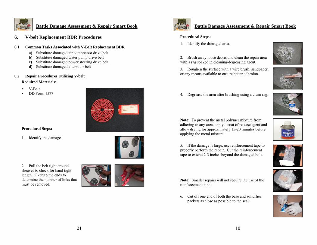
6. V-belt Replacement BDR Procedures Procedural Steps:
1. Identify the damaged area. 6.1 Common Tasks Associated with V-Belt Replacement BDR
a) Substitute damaged air compressor drive belt b) Substitute damaged water pump drive belt 2. Brush away loose debris and clean the repair area
with a rag soaked in cleaning/degreasing agent. c) Substitute damaged power steering drive belt d) Substitute damaged alternator belt 3. Roughen the surface with a wire brush, sandpaper,
or any means available to ensure better adhesion. 6.2 Repair Procedures Utilizing V-belt Required Materials:
• V-Belt
• DD Form 1577
Procedural Steps: 1. Identify the damage.
2. Pull the belt tight around sheaves to check for hand tight length. Overlap the ends to determine the number of links that must be removed.
4. Degrease the area after brushing using a clean rag.
Note: To prevent the metal polymer mixture from adhering to any area, apply a coat of release agent and allow drying for approximately 15-20 minutes before applying the metal mixture.
5. If the damage is large, use reinforcement tape to properly perform the repair. Cut the reinforcement tape to extend 2-3 inches beyond the damaged hole.
Note: Smaller repairs will not require the use of the reinforcement tape.
6. Cut off one end of both the base and solidifier
packets as close as possible to the seal.

Battle Damage Assessment & Repair Smart Book
Battle Damage Assessment & Repair Smart Book
11
20
7. Using the straight edge of the mixing spatula or other suitable mixing tool, squeeze out the entire contents of the packets onto a working surface.
3. Twist the ends of the wire clockwise if frayed. Put the two wire ends together and again twist clockwise.
8. Mix the two components thoroughly to achieve a uniform material free of any streaks.
Note: Be prepared to apply the metal mixture quickly to the damaged area. The working times for the product are as follows:
Temperature 41° F (5° C)
59° F (15° C)
77° F (25° C)
Use all material within 5 min 4 min 3 min 9. Apply the metal mixture to the area and approximately 2-3 inches around the damaged area. 10. If needed, apply the reinforcement tape by dabbing it into the first coat of the metal mixture. 11. Apply the final coat of metal mixture over the reinforcement tape. Ensure all ends and sides of the tape are thoroughly covered.
Note: When applying metal mixture, press down firmly to ensure maximum contact with the surface. This will also remove any air trapped during the mixing process.
12. Clean the mixing tools immediately after use with cleaning/degreasing agent.
4. Trim the wire ends and any excess individual wires from the twisted pair. Determine the size othe electrical connector.
f
5. Fill the connector ¾ full of RTV silicone. Insert the wires into the connector.
6. Twist the electrical connector clockwise until it stops or feels snug. After the connector has been installed, gently pull the wire ends to make sure they are properly connected.
7. Document the repair on a DD Form 1577 or fabricated tag and place on or near the repair. Annotate the repair on DA Form 5988E/DA Form 2404 and turn in to maintenance personnel.
Note: If unable to place the DD Form 1577 on or near repair area, place it on an item such as the steering wheel or starter switch so maintenance personnel will be aware of the repair.

Battle Damage Assessment & Repair Smart Book
Battle Damage Assessment & Repair Smart Book
19
12
5. Electrical BDR Procedures 13. Document the repair on a DD Form 1577 or fabricated tag and place on or near the repair. Annotate the repair on DA Form 5988E/DA Form 2404 and turn in to maintenance personnel. 5.1 Common Tasks Associated with Electrical BDR a) Bypass damaged neutral safety switch by connecting wires
together Note: If unable to place the DD Form 1577 on or near repair area, place it on an item such as the steering wheel or starter switch so maintenance personnel will be aware of the repair.
b) Bypass damaged temperature sensor using 16/22 gauge wire c) Bypass damaged oil pressure sensor using 16/22 gauge wire d) Bypass damaged fuel sensor using 16/22 gauge wire e) Repair damage wire f) Repair damaged cable Note: Bulk acquisition of polymer training packets is available for units.
These packets contain approximately ⅓ the amount of the same material as the BDAR kit packets at a fraction of the cost.
g) Bypass faulty pin on cannon plug
5.2 Repair Procedures for Electrical Repairs Required Materials: METAL POLYMER TRAINING PACKETS
NSN: 8030-01-544-7525 • Electrical connectors Available as bulk purchase = 250 pairs per box. • Electrical tape • 16 or 22 gauge wire • Mini utility knife • DD Form 1577 • RTV silicone
Procedural Steps:
1. Identify the damage.
Note: Turn off all electrical power, and disconnect the battery.
2. Prepare the wire ends by cutting them flush. Strip the wire approximately one half inch from the end of the wire with mini utility knife.

Battle Damage Assessment & Repair Smart Book
Battle Damage Assessment & Repair Smart Book
13
18
15. Document the repair on a DD Form 1577 or fabricated tag and place on or near the repair. Annotate the repair on DA Form 5988E/DA Form 2404 and turn in to maintenance personnel.
3.2 Metal Stick BDR Procedures 3.2.1 Common Tasks Associated with Metal Stick BDR
Note: If unable to place the DD Form 1577 on or near repair area, place it on an item such as the steering wheel or starter switch so maintenance personnel will be aware of the repair.
a) Repair damaged air filter housing b) Repair damaged engine manifolds c) Repair damaged radiator d) Repair damaged metal oil line e) Repair damaged battery post f) Repair damaged air tank Note: Bulk acquisition of polymer training packets is available for units.
These packets contain approximately ⅓ the amount of the same material as the BDAR kit packets at a fraction of the cost.
g) Repair hole in fuel cell h) Repair hole in hydraulic tank
3.2.2 Repair Procedures Utilizing Metal Stick
Required Materials: RUBBER POLYMER TRAINING PACKETS
NSN: 8040-01-544-9465 Available as bulk purchase = 250 pairs per box.
• Metal repair stick • Cleaning/degreasing agent • Wire brush • 40-grit sandpaper • Rag (not in kit) • Goggles (not in kit) • Latex gloves • Dust mask • Mini utility knife • DD Form 1577 Procedural Steps:
1. Identify the damage.
2. Wipe away excess debris from the damaged area. Clean with a rag soaked in cleaning/ degreasing agent to remove any oil or fuel from area.
Battle Damage Assessment & Repair Smart Book
Battle Damage Assessment & Repair Smart Book
17
14
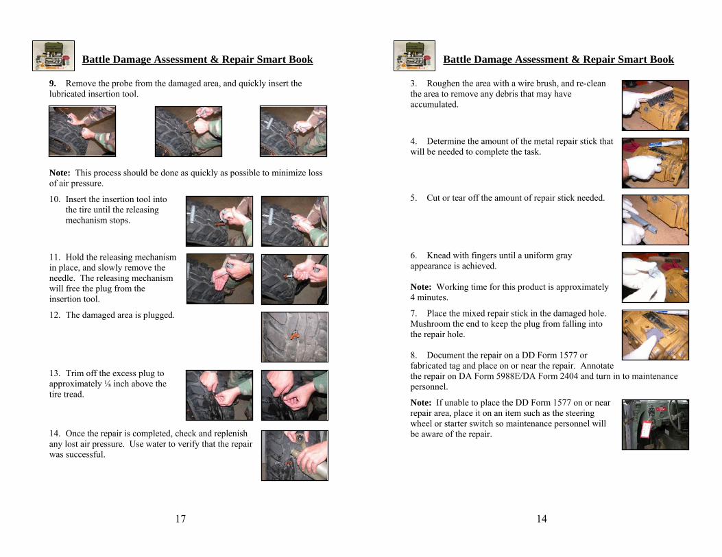
9. Remove the probe from the damaged area, and quickly insert the lubricated insertion tool.
3. Roughen the area with a wire brush, and re-clean the area to remove any debris that may have accumulated.
Note: This process should be done as quickly as possible to minimize loss of air pressure.
10. Insert the insertion tool into the tire until the releasing mechanism stops.
11. Hold the releasing mechanism in place, and slowly remove the needle. The releasing mechanism will free the plug from the insertion tool.
12. The damaged area is plugged.
13. Trim off the excess plug to approximately ⅛ inch above the tire tread.
14. Once the repair is completed, check and replenish any lost air pressure. Use water to verify that the repair was successful.
4. Determine the amount of the metal repair stick that will be needed to complete the task. 5. Cut or tear off the amount of repair stick needed. 6. Knead with fingers until a uniform gray appearance is achieved. Note: Working time for this product is approximately 4 minutes.
7. Place the mixed repair stick in the damaged hole. Mushroom the end to keep the plug from falling into the repair hole. 8. Document the repair on a DD Form 1577 or fabricated tag and place on or near the repair. Annotate the repair on DA Form 5988E/DA Form 2404 and turn in to maintenance personnel.
Note: If unable to place the DD Form 1577 on or near repair area, place it on an item such as the steering wheel or starter switch so maintenance personnel will be aware of the repair.

Battle Damage Assessment & Repair Smart Book
Battle Damage Assessment & Repair Smart Book
15
16
4. Tire Plug BDR Procedures 4. Use pliers to remove any object embedded in the tire.
4.1 Common Tasks Associated with Tire Plug BDR a) Repair tire sidewall (see Chapter 2) b) Repair damaged tire with tire plug
4.2 Repair Procedure Utilizing Tire Plug Required Materials:
• Spiral probe tool • Insertion tool • Lubricant • Vulcanizing plugs • Mini utility knife • DD Form 1577 • Pliers • Canteen (not in kit) • Rag (not in kit)
Procedural Steps:
1. Identify the damage.
Note: This procedure can be performed while the tire is mounted on the vehicle.
2. Remove dirt, mud, and particles from around the damaged area.
3. Lightly coat the probe with lubricant.
5. Immediately after the object is removed, insert the lubricated probe. This step may require some force and a twisting action to insert the probe fully. The probe separates the steel belts in the tire and prepares the damaged area for the tire insertion tool.
Note: Speed is important to limit the amount of air pressure lost.
6. Remove vulcanizing plug from the packaging.
Note: More than one vulcanizing plug can be placed in the damaged area. This will be determined by the size of the damaged area.
7. Insert the vulcanizing plug into the insertion tool.
Note: Two vulcanizing plugs can be placed on the insertion tool at a time, if required.
8. Lightly coat the insertion tool with lubricant.