Traditional Design of Cage Rotor Induction Motors · Traditional Design of Cage Rotor Induction...
35
Traditional Design of Cage Rotor Induction Motors Ronald G. Harley and Yao Duan Georgia Institute of Technology November, 2009
Transcript of Traditional Design of Cage Rotor Induction Motors · Traditional Design of Cage Rotor Induction...
Traditional Design of Cage
Rotor Induction Motors
Ronald G. Harley and Yao Duan
Georgia Institute of Technology
November, 2009
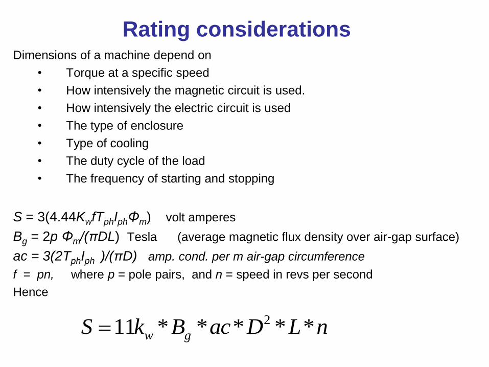
Rating considerationsDimensions of a machine depend on
• Torque at a specific speed
• How intensively the magnetic circuit is used.
• How intensively the electric circuit is used
• The type of enclosure
• Type of cooling
• The duty cycle of the load
• The frequency of starting and stopping
S = 3(4.44KwfTphIphΦm) volt amperes
Bg = 2p Φm/(πDL) Tesla (average magnetic flux density over air-gap surface)
ac = 3(2TphIph )/(πD) amp. cond. per m air-gap circumference
f = pn, where p = pole pairs, and n = speed in revs per second
Hence
211 * * * * *w gS k B ac D L n
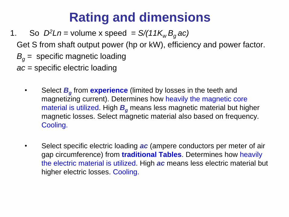
Rating and dimensions1. So D2Ln = volume x speed = S/(11Kw Bg ac)
Get S from shaft output power (hp or kW), efficiency and power factor.
Bg = specific magnetic loading
ac = specific electric loading
• Select Bg from experience (limited by losses in the teeth and
magnetizing current). Determines how heavily the magnetic core
material is utilized. High Bg means less magnetic material but higher
magnetic losses. Select magnetic material also based on frequency.
Cooling.
• Select specific electric loading ac (ampere conductors per meter of air
gap circumference) from traditional Tables. Determines how heavily
the electric material is utilized. High ac means less electric material but
higher electric losses. Cooling.
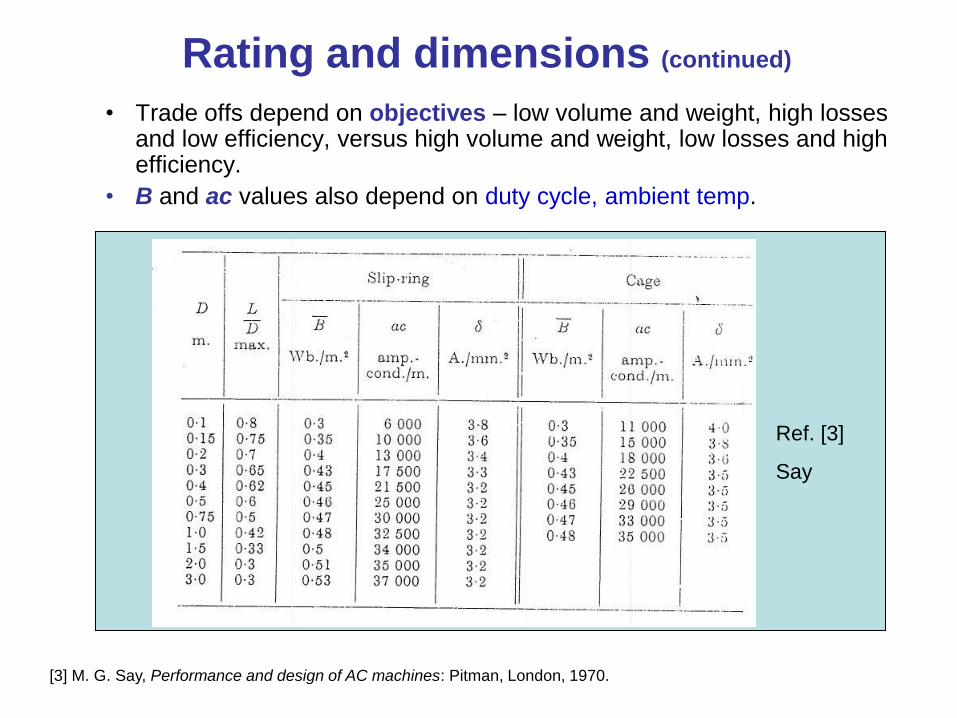
Rating and dimensions (continued)
• Trade offs depend on objectives – low volume and weight, high losses and low efficiency, versus high volume and weight, low losses and high efficiency.
• B and ac values also depend on duty cycle, ambient temp.
Ref. [3]
Say
[3] M. G. Say, Performance and design of AC machines: Pitman, London, 1970.
Efficiency and power factor
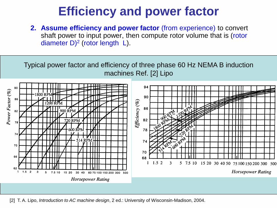
2. Assume efficiency and power factor (from experience) to convert shaft power to input power, then compute rotor volume that is (rotor diameter D)2 (rotor length L).
Typical power factor and efficiency of three phase 60 Hz NEMA B induction
machines Ref. [2] Lipo
[2] T. A. Lipo, Introduction to AC machine design, 2 ed.: University of Wisconsin-Madison, 2004.
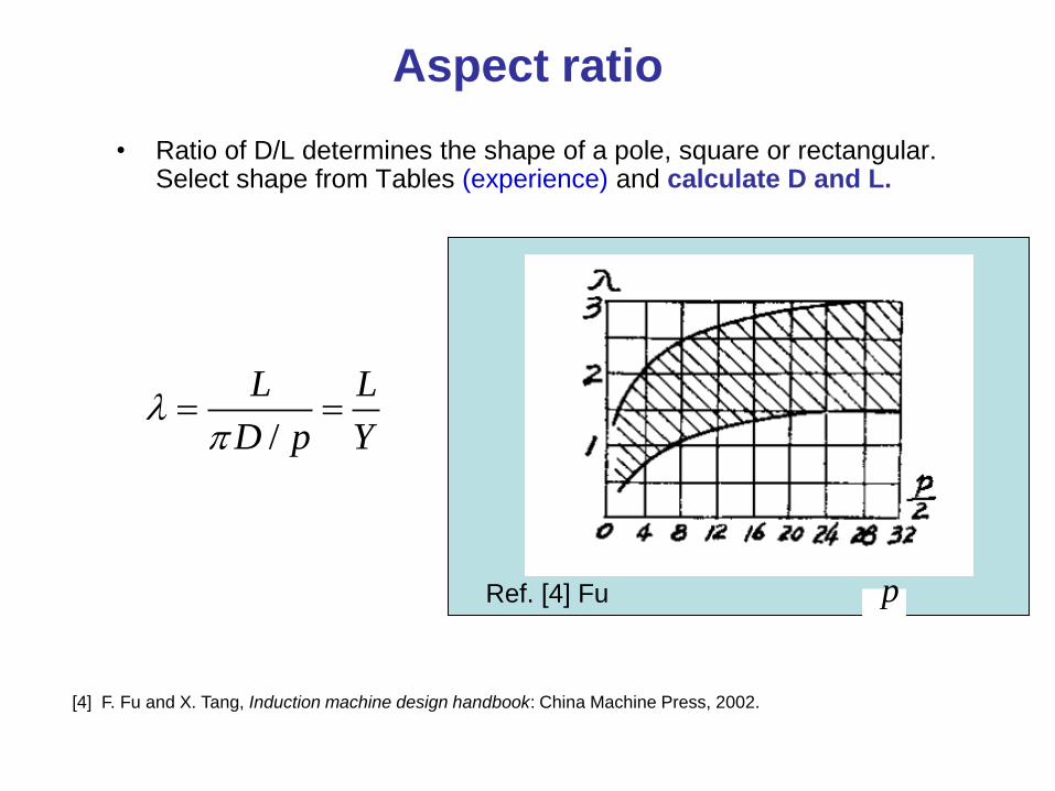
Aspect ratio
• Ratio of D/L determines the shape of a pole, square or rectangular. Select shape from Tables (experience) and calculate D and L.
/
L L
D p Y
pRef. [4] Fu
[4] F. Fu and X. Tang, Induction machine design handbook: China Machine Press, 2002.
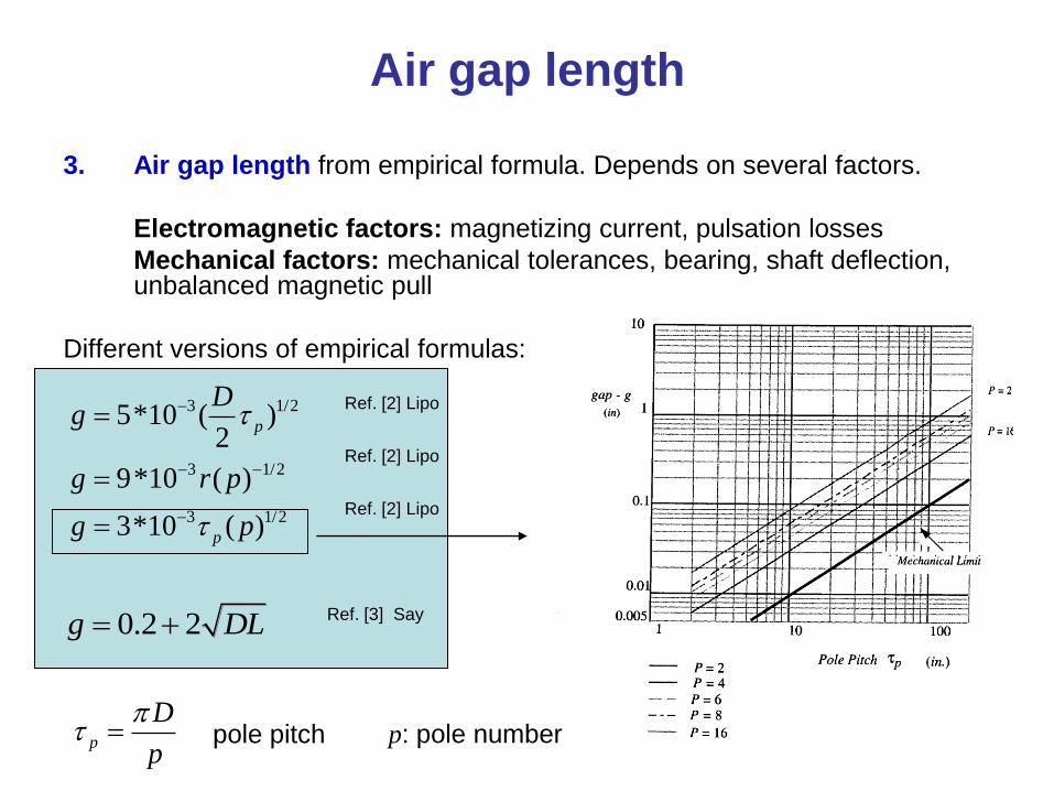
Air gap length
3. Air gap length from empirical formula. Depends on several factors.
Electromagnetic factors: magnetizing current, pulsation losses
Mechanical factors: mechanical tolerances, bearing, shaft deflection, unbalanced magnetic pull
Different versions of empirical formulas:
3 1/2
3 1/2
3 1/2
5*10 ( )2
9*10 ( )
3*10 ( )
p
p
Dg
g r p
g p
0.2 2g DL
p
D
p
pole pitch
Ref. [2] Lipo
Ref. [3] Say
p: pole number
Ref. [2] Lipo
Ref. [2] Lipo
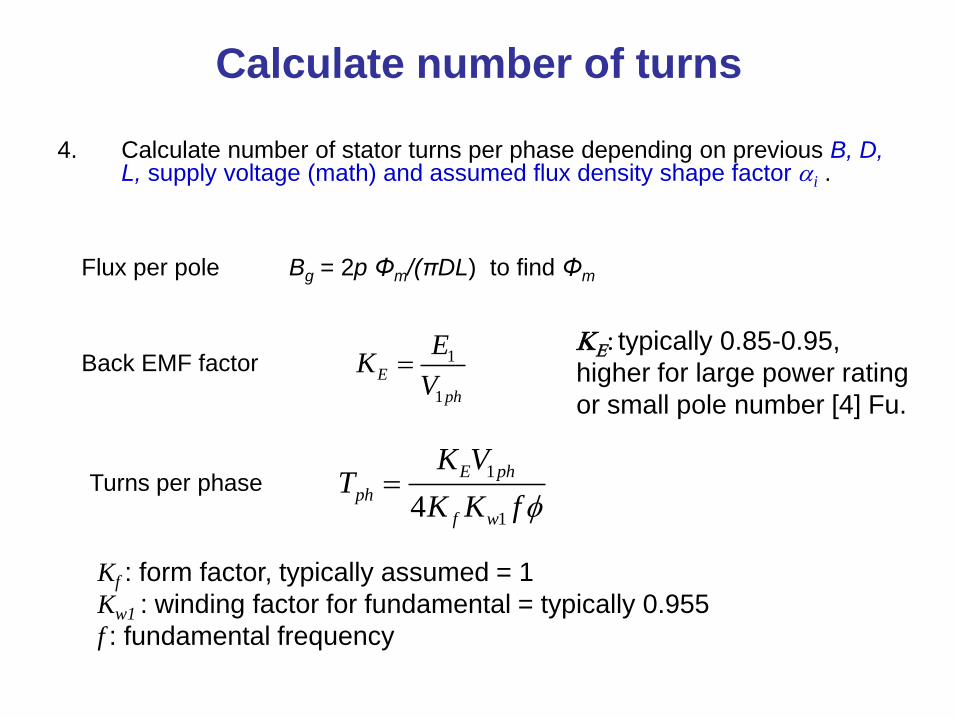
Calculate number of turns
4. Calculate number of stator turns per phase depending on previous B, D,L, supply voltage (math) and assumed flux density shape factor ai .
1
14
E ph
ph
f w
K VT
K K f
1
1
E
ph
EK
V
Flux per pole
Back EMF factor
Turns per phase
KE: typically 0.85-0.95,
higher for large power rating
or small pole number [4] Fu.
Kf : form factor, typically assumed = 1
Kw1 : winding factor for fundamental = typically 0.955
f : fundamental frequency
Bg = 2p Φm/(πDL) to find Φm
Select number of stator slots
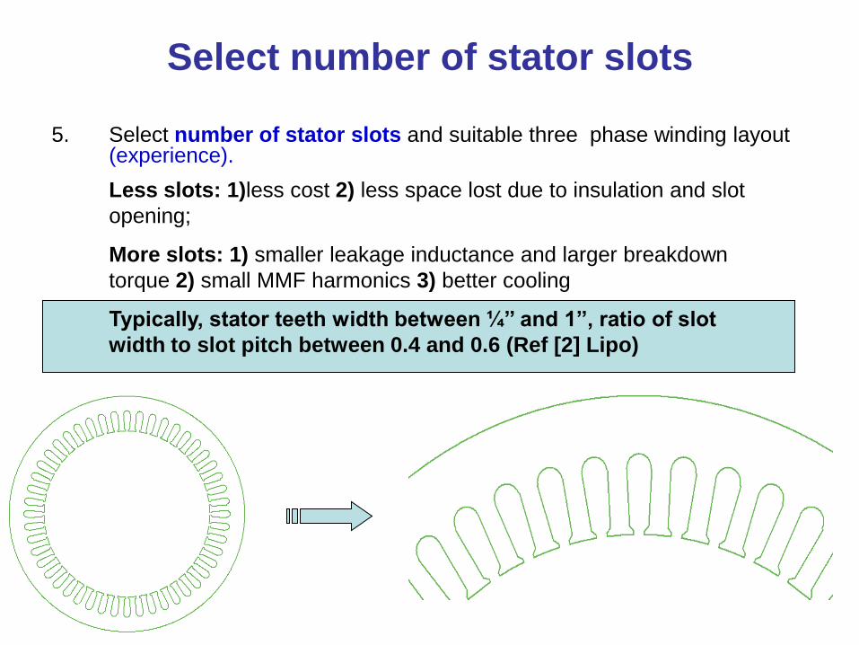
5. Select number of stator slots and suitable three phase winding layout (experience).
Less slots: 1)less cost 2) less space lost due to insulation and slot
opening;
More slots: 1) smaller leakage inductance and larger breakdown
torque 2) small MMF harmonics 3) better cooling
Typically, stator teeth width between ¼’’ and 1’’, ratio of slot
width to slot pitch between 0.4 and 0.6 (Ref [2] Lipo)
Stator slot geometry
• In small motors with small diameters the taper on the tooth or slot is significant and tapered slots (parallel sided teeth) are used. This gives maximum area of slot for given tooth flux density. Round wires of small gauge are used since they are easy to wind and do not mind the taper of the slot.
• In larger machines with larger diameters, the tooth taper is much less and often strip conductors are used which need parallel sided slots, thus tapered teeth.
Stator slot sizing
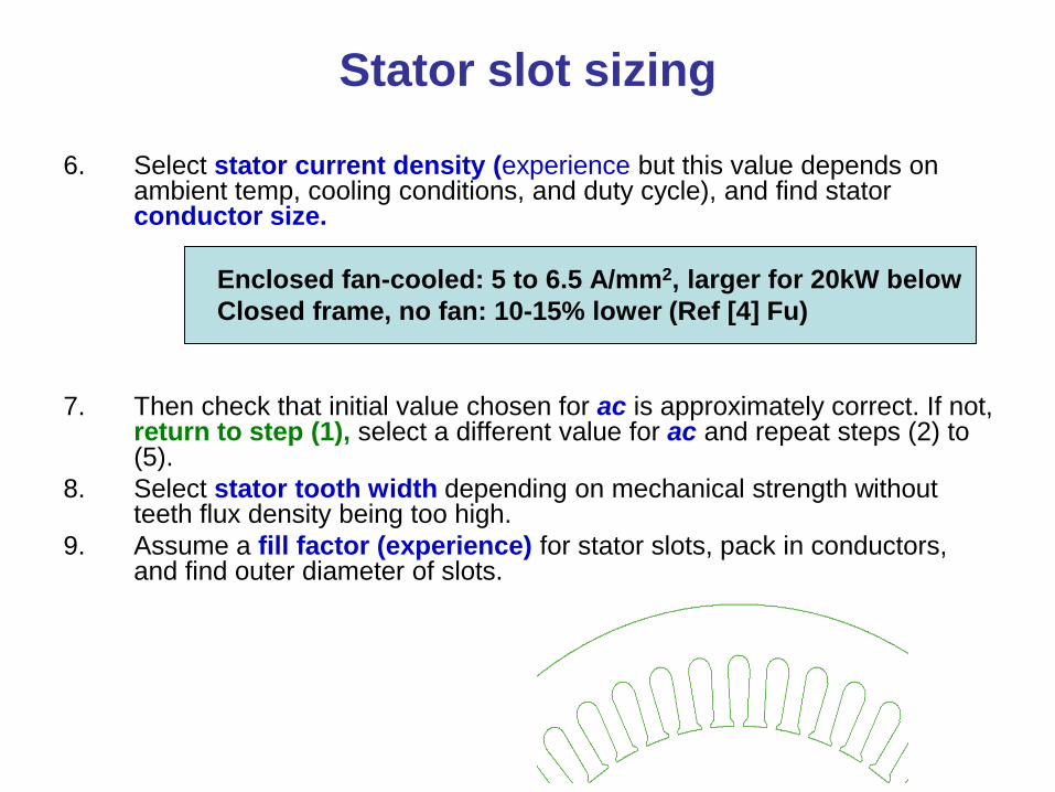
6. Select stator current density (experience but this value depends on ambient temp, cooling conditions, and duty cycle), and find stator conductor size.
Enclosed fan-cooled: 5 to 6.5 A/mm2, larger for 20kW below
Closed frame, no fan: 10-15% lower (Ref [4] Fu)
7. Then check that initial value chosen for ac is approximately correct. If not, return to step (1), select a different value for ac and repeat steps (2) to (5).
8. Select stator tooth width depending on mechanical strength without teeth flux density being too high.
9. Assume a fill factor (experience) for stator slots, pack in conductors, and find outer diameter of slots.
Select flux density
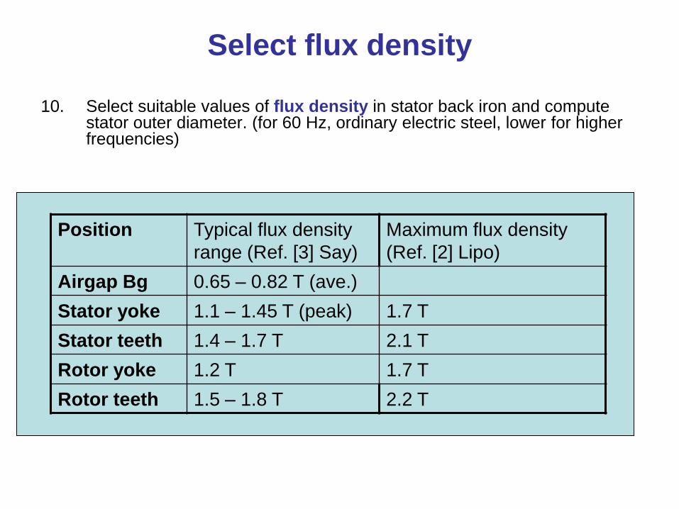
10. Select suitable values of flux density in stator back iron and compute stator outer diameter. (for 60 Hz, ordinary electric steel, lower for higher frequencies)
Position Typical flux density
range (Ref. [3] Say)
Maximum flux density
(Ref. [2] Lipo)
Airgap Bg 0.65 – 0.82 T (ave.)
Stator yoke 1.1 – 1.45 T (peak) 1.7 T
Stator teeth 1.4 – 1.7 T 2.1 T
Rotor yoke 1.2 T 1.7 T
Rotor teeth 1.5 – 1.8 T 2.2 T
Calculate stator winding resistance
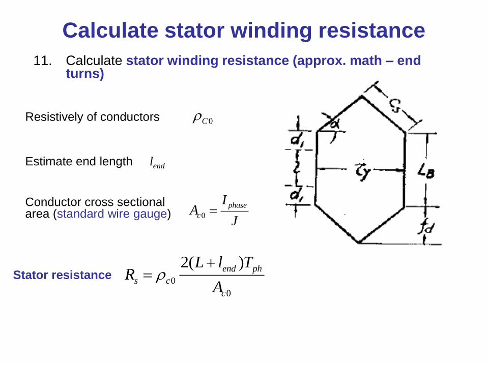
11. Calculate stator winding resistance (approx. math – end turns)
Resistively of conductors
Estimate end length lend
0C
0
0
2( )end ph
s c
c
L l TR
A
Stator resistance
Conductor cross sectional area (standard wire gauge) 0
phase
c
IA
J
Select number of rotor slots
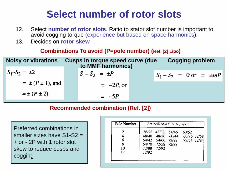
12. Select number of rotor slots. Ratio to stator slot number is important to avoid cogging torque (experience but based on space harmonics).
13. Decides on rotor skew
Noisy or vibrations Cusps in torque speed curve (due to MMF harmonics)
Cogging problem
Recommended combination (Ref. [2])
Combinations To avoid (P=pole number) (Ref. [2] Lipo)
Preferred combinations in
smaller sizes have S1-S2 =
+ or - 2P with 1 rotor slot
skew to reduce cusps and
cogging
Rotor bar
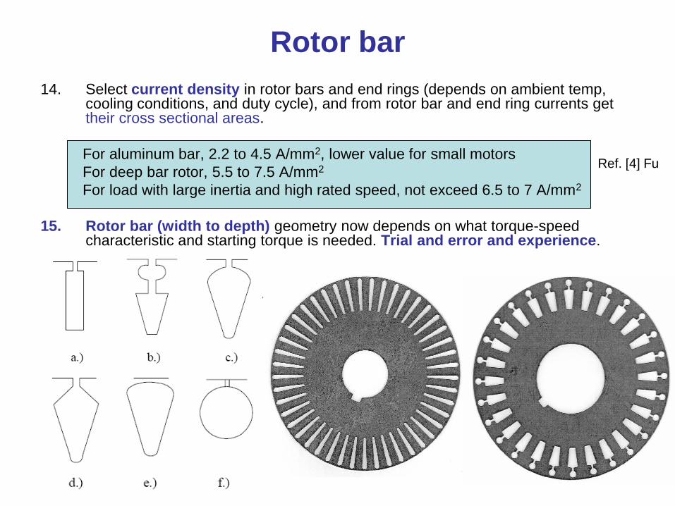
14. Select current density in rotor bars and end rings (depends on ambient temp, cooling conditions, and duty cycle), and from rotor bar and end ring currents get their cross sectional areas.
For aluminum bar, 2.2 to 4.5 A/mm2, lower value for small motors
For deep bar rotor, 5.5 to 7.5 A/mm2
For load with large inertia and high rated speed, not exceed 6.5 to 7 A/mm2
15. Rotor bar (width to depth) geometry now depends on what torque-speed characteristic and starting torque is needed. Trial and error and experience.
Ref. [4] Fu
Skin effect
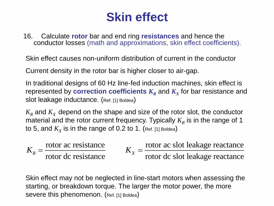
16. Calculate rotor bar and end ring resistances and hence the conductor losses (math and approximations, skin effect coefficients).
Skin effect causes non-uniform distribution of current in the conductor
Current density in the rotor bar is higher closer to air-gap.
In traditional designs of 60 Hz line-fed induction machines, skin effect is
represented by correction coefficients KR and KX for bar resistance and
slot leakage inductance. (Ref. [1] Boldea)
KR and KX depend on the shape and size of the rotor slot, the conductor
material and the rotor current frequency. Typically KR is in the range of 1
to 5, and KX is in the range of 0.2 to 1. (Ref. [1] Boldea)
Skin effect may not be neglected in line-start motors when assessing the
starting, or breakdown torque. The larger the motor power, the more
severe this phenomenon. (Ref. [1] Boldea)
rotor ac resistance
rotor dc resistanceRK
rotor ac slot leakage reactance
rotor dc slot leakage reactanceXK
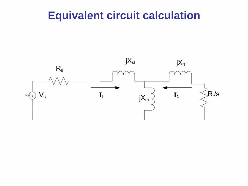
Equivalent circuit calculation
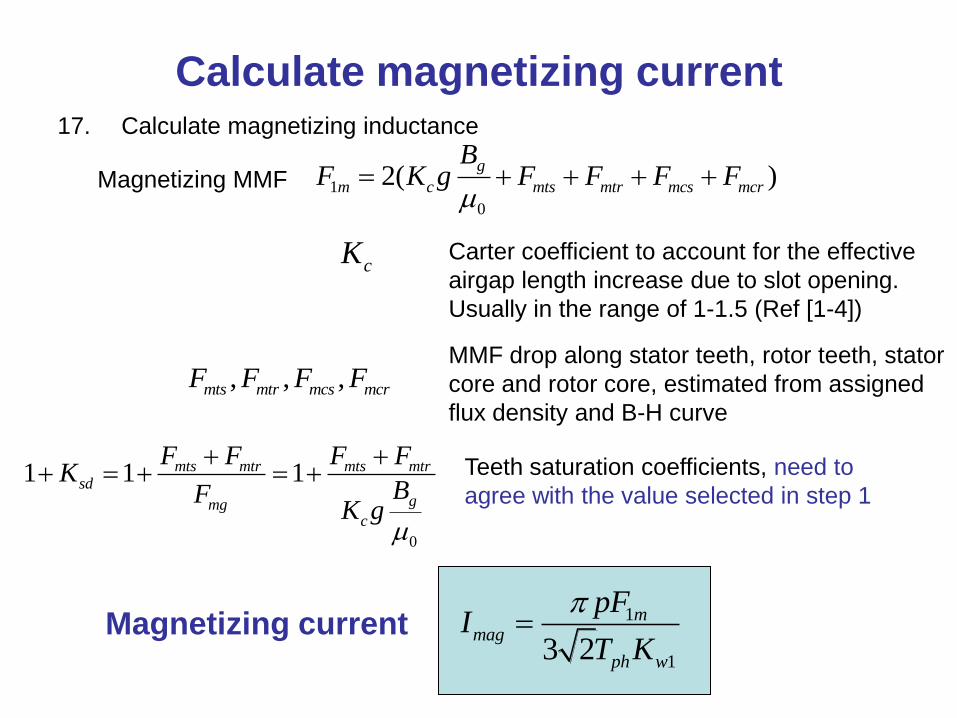
Calculate magnetizing current17. Calculate magnetizing inductance
Magnetizing MMF 1
0
2( )g
m c mts mtr mcs mcr
BF K g F F F F
Carter coefficient to account for the effective
airgap length increase due to slot opening.
Usually in the range of 1-1.5 (Ref [1-4])
, , ,mts mtr mcs mcrF F F F
cK
MMF drop along stator teeth, rotor teeth, stator
core and rotor core, estimated from assigned
flux density and B-H curve
0
1 1 1mts mtr mts mtrsd
gmgc
F F F FK
BFK g
Teeth saturation coefficients, need to
agree with the value selected in step 1
1
13 2
mmag
ph w
pFI
T K
Magnetizing current
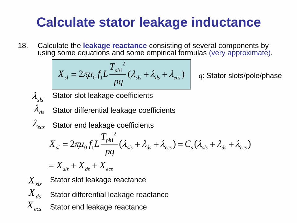
Calculate stator leakage inductance
18. Calculate the leakage reactance consisting of several components by using some equations and some empirical formulas (very approximate).
2
1
0 12 ( )ph
sl sls ds ecs
TX f L
pq
sls
ds
ecs
Stator slot leakage coefficients
Stator differential leakage coefficients
Stator end leakage coefficients
q: Stator slots/pole/phase
2
1
0 12 ( ) ( )ph
sl sls ds ecs s sls ds ecs
sls ds ecs
TX f L C
pq
X X X
Stator slot leakage reactance
Stator differential leakage reactance
Stator end leakage reactance
slsX
dsX
ecsX
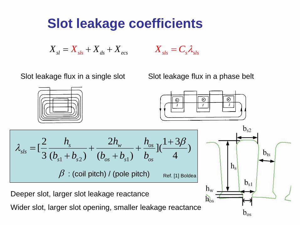
Slot leakage coefficients
sls s slsX C
1 2 1
22 1 3[ ]( )3 ( ) ( ) 4
s w ossls
s s os s os
h h h
b b b b b
: (coil pitch) / (pole pitch)
Deeper slot, larger slot leakage reactance
Wider slot, larger slot opening, smaller leakage reactance
Slot leakage flux in a single slot Slot leakage flux in a phase belt
Ref. [1] Boldea
slssl ds ecsX XX X
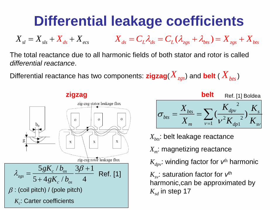
Differential leakage coefficients
The total reactance due to all harmonic fields of both stator and rotor is called
differential reactance.
Differential reactance has two components: zigzag( ) and belt ( )
zigzag
5 / 3 1
5 4 / 4
c oszgs
c os
gK b
gK b
belt
2
2 21 1
( )dpvbts s
bts
m dp s
KX K
X K K
Xbts: belt leakage reactance
Xm: magnetizing reactance
Kdpv: winding factor for vth harmonic
Ksv: saturation factor for vth
harmonic,can be approximated by
Ksd in step 17
Ref. [1]
Ref. [1] Boldea
: (coil pitch) / (pole pitch)
Kc: Carter coefficients
sl sls ds ecsX X X X ( )ds L ds L zgs bts zgs btsX C C X X
zgsXbtsX
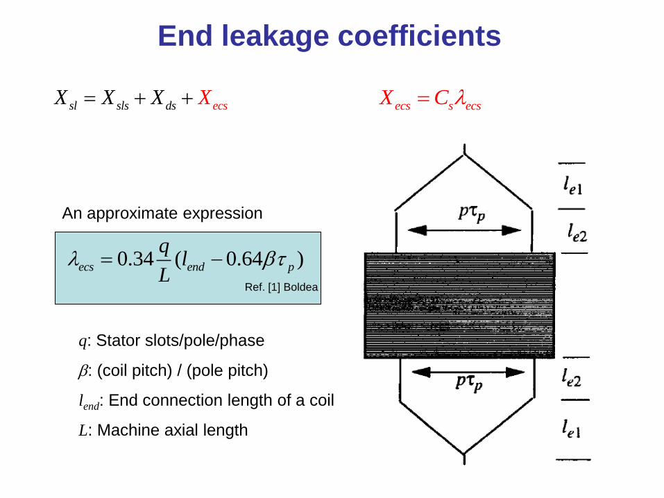
End leakage coefficients
0.34 ( 0.64 )ecs end p
ql
L
An approximate expression
q: Stator slots/pole/phase
: (coil pitch) / (pole pitch)
lend: End connection length of a coil
L: Machine axial length
Ref. [1] Boldea
sl sls ds ecsX X X X ecs s ecsX C
Calculate rotor leakage inductance
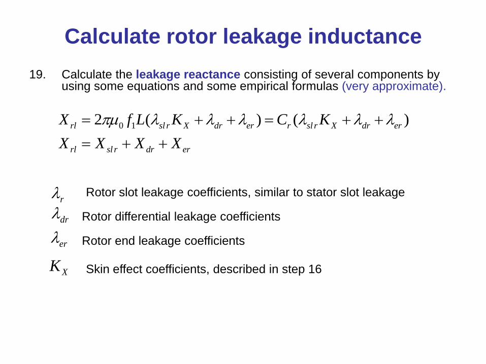
19. Calculate the leakage reactance consisting of several components by using some equations and some empirical formulas (very approximate).
0 12 ( ) ( )rl sl r X dr er r sl r X dr er
rl sl r dr er
X f L K C K
X X X X
r
dr
er
Rotor slot leakage coefficients, similar to stator slot leakage
Rotor differential leakage coefficients
Rotor end leakage coefficients
XK Skin effect coefficients, described in step 16
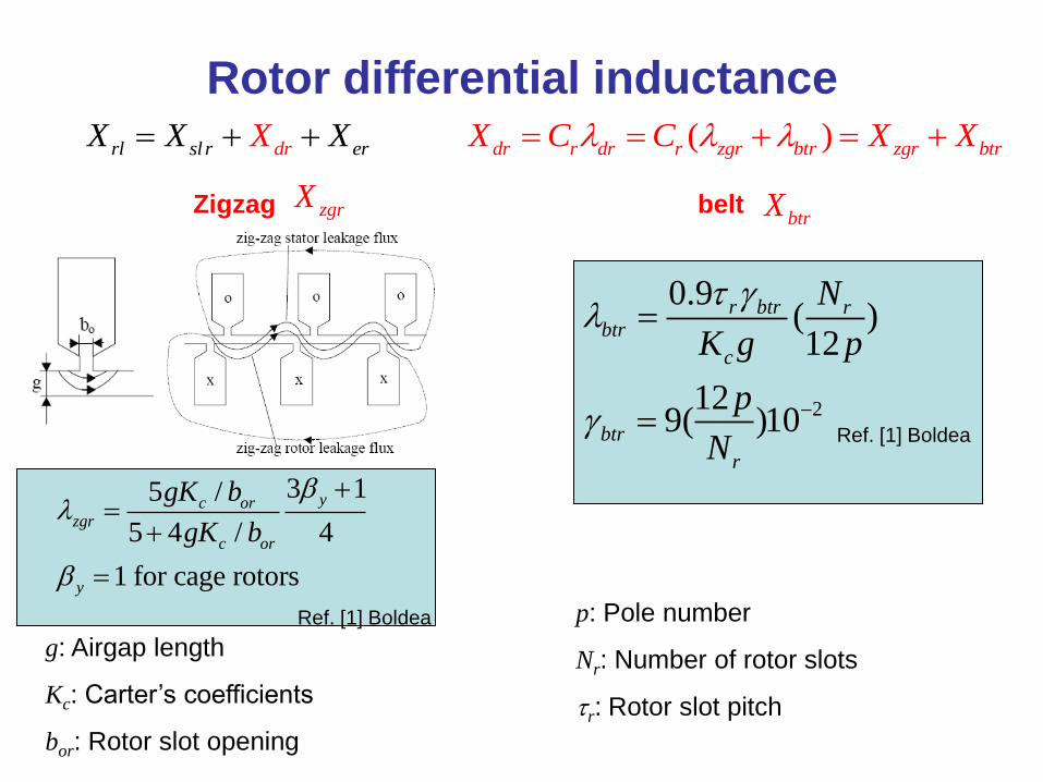
Rotor differential inductance
Zigzag
3 15 /
5 4 / 4
1 for cage rotors
yc orzgr
c or
y
gK b
gK b
belt
2
0.9( )12
129( )10
r btr rbtr
c
btr
r
N
K g p
p
N
g: Airgap length
Kc: Carter’s coefficients
bor: Rotor slot opening
Ref. [1] Boldea
Ref. [1] Boldea
p: Pole number
Nr: Number of rotor slots
r: Rotor slot pitch
rl sl r d errXX X X ( )dr r dr r zgr btr zgr btrX C C X X
zgrXbtrX
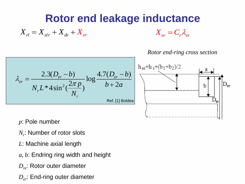
Rotor end leakage inductance
2
2.3( ) 4.7( )log
2 2*4sin ( )
er erer
r
r
D b D b
p b aN L
N
Ref. [1] Boldea
Rotor end-ring cross section
p: Pole number
Nr: Number of rotor slots
L: Machine axial length
a, b: Endring ring width and height
Dre: Rotor outer diameter
Der: End-ring outer diameter
rl sl r r erdX X X X er r erX C
Finite Element Analysis (FEA) calculation• FEA is based on numerical solution of the magnetic field. The FEA calculation is
not based on analytical theories, such as the classical equivalent circuit shown before.
• Designer’s input to FEA is the physical geometry of the machine, material properties, the excitation applied to the winding (current source or voltage source), and the load of the machine.
• Output of FEA is the overall performance of machine, such as winding current (if voltage source applied), shaft torque, rotor speed at a certain mechanical load.
• Copper loss is calculated off-line from the FEA solution of current and the calculated resistance by the designer.
• Core loss is mostly approximated from the flux density solution in the core and the material datasheet and calculated off-line.
• FEA calculation treats the machine as a whole object. It can neither directly calculate the values of reactances and resistances in the equivalent circuit, nor calculate the individual components of leakage inductances (slot leakage, differential leakage, etc.)
• Designer calculates efficiency and power factor off-line based on FEA torque and current.
• In 2D FEA, the end effect is approximated by equivalent circuit comprised of resistances and reactances, which is an input from the designer. 3D FEA can include the end effect in its calculation.
• FEA is time consuming. 2D FEA takes hours for simulation the performance of a design. 3 D FEA takes days.
Calculate performance
20. Several text books show how to compute rotor bar and end ring currents, resistances, and conductor losses. From this find rotor resistance of an equivalent rotor phase. Now the equivalent circuit is complete.
21. Use FEA to check for any flux density violations.
22. Calculate all iron losses (off-line) approximately from material data sheets of losses in W/kg depending on flux density and frequency.
23. Assume friction and windage as typically 1% of input power.
24. All the elements of the equivalent circuit have now been determined. Use this to compute efficiency and power factor at full load. If these do not agree closely with assumed values in step (1), then return to step (1) and repeat all the steps (2) to (17)
Traditional induction motor design steps (continued)
25. Calculate motor performance data from equivalent circuit and compare with results from FEA:
• Slip at full load
• Starting current and torque
• Torque-speed curve (if not acceptable then change rotor slot geometry and return to step 12)
• Torque ripple if fed from converter
26. Mechanical design
27. Thermal design. If temp rises are too high, either increase cooling by adding heat sink fins for example, or return to step (1), adjust choice of magnetic loadings and/or electric loading, and repeat design.
28. Calculate weight and volume.
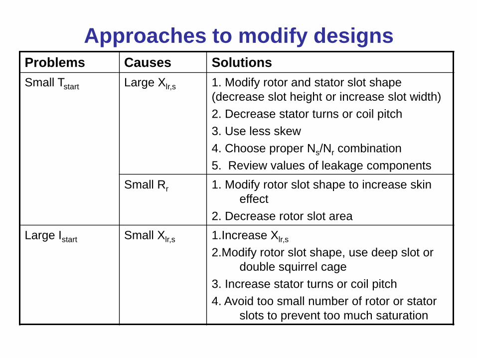
Approaches to modify designsProblems Causes Solutions
Small Tstart Large Xlr,s 1. Modify rotor and stator slot shape
(decrease slot height or increase slot width)
2. Decrease stator turns or coil pitch
3. Use less skew
4. Choose proper Ns/Nr combination
5. Review values of leakage components
Small Rr 1. Modify rotor slot shape to increase skin
effect
2. Decrease rotor slot area
Large Istart Small Xlr,s 1.Increase Xlr,s
2.Modify rotor slot shape, use deep slot or
double squirrel cage
3. Increase stator turns or coil pitch
4. Avoid too small number of rotor or stator
slots to prevent too much saturation
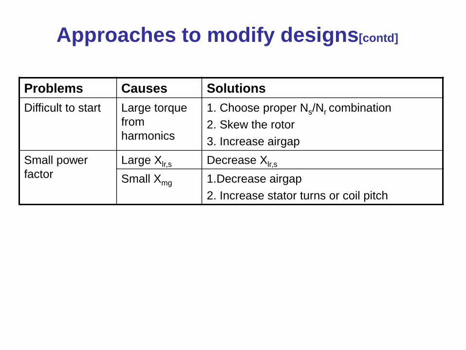
Approaches to modify designs[contd]
Problems Causes Solutions
Difficult to start Large torque
from
harmonics
1. Choose proper Ns/Nr combination
2. Skew the rotor
3. Increase airgap
Small power
factor
Large Xlr,s Decrease Xlr,s
Small Xmg 1.Decrease airgap
2. Increase stator turns or coil pitch
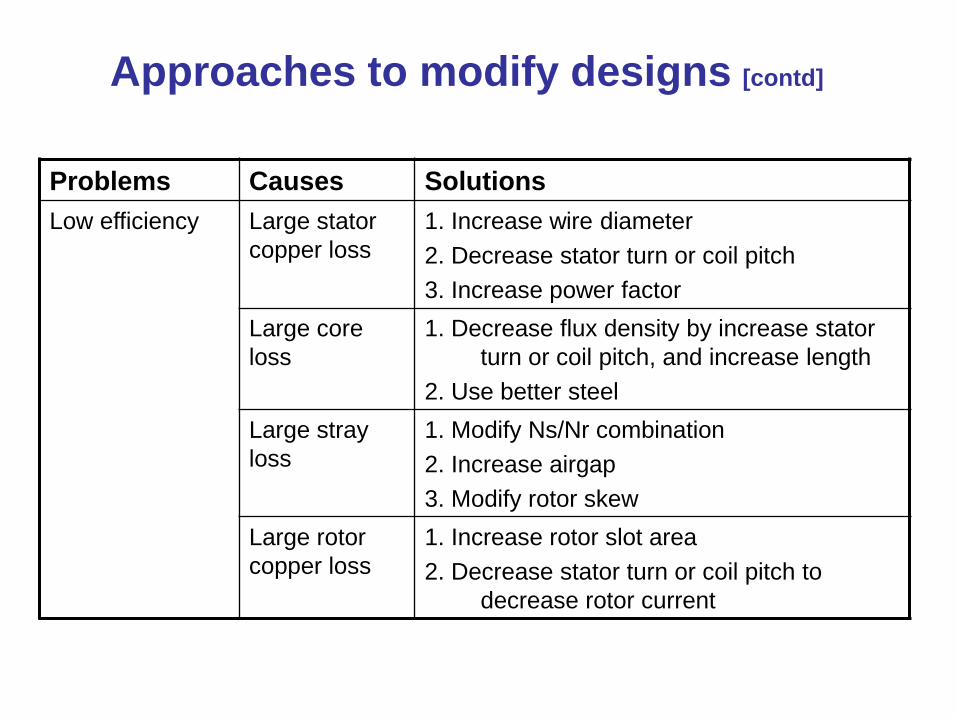
Approaches to modify designs [contd]
Problems Causes Solutions
Low efficiency Large stator
copper loss
1. Increase wire diameter
2. Decrease stator turn or coil pitch
3. Increase power factor
Large core
loss
1. Decrease flux density by increase stator
turn or coil pitch, and increase length
2. Use better steel
Large stray
loss
1. Modify Ns/Nr combination
2. Increase airgap
3. Modify rotor skew
Large rotor
copper loss
1. Increase rotor slot area
2. Decrease stator turn or coil pitch to
decrease rotor current
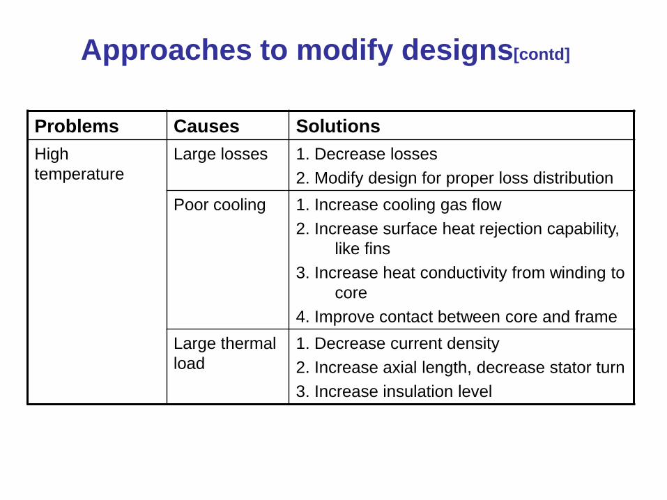
Approaches to modify designs[contd]
Problems Causes Solutions
High
temperature
Large losses 1. Decrease losses
2. Modify design for proper loss distribution
Poor cooling 1. Increase cooling gas flow
2. Increase surface heat rejection capability,
like fins
3. Increase heat conductivity from winding to
core
4. Improve contact between core and frame
Large thermal
load
1. Decrease current density
2. Increase axial length, decrease stator turn
3. Increase insulation level
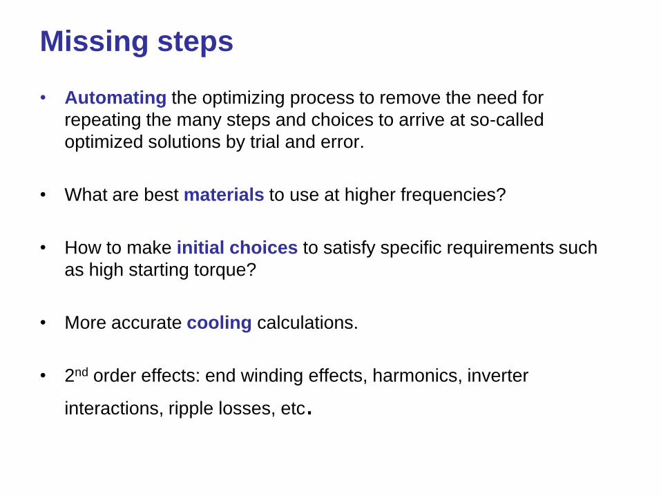
Missing steps
• Automating the optimizing process to remove the need for
repeating the many steps and choices to arrive at so-called
optimized solutions by trial and error.
• What are best materials to use at higher frequencies?
• How to make initial choices to satisfy specific requirements such
as high starting torque?
• More accurate cooling calculations.
• 2nd order effects: end winding effects, harmonics, inverter
interactions, ripple losses, etc.
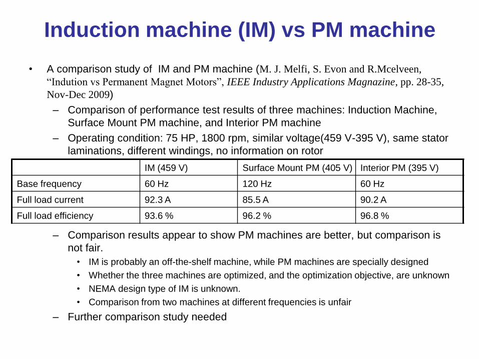
Induction machine (IM) vs PM machine
• A comparison study of IM and PM machine (M. J. Melfi, S. Evon and R.Mcelveen,
“Indution vs Permanent Magnet Motors”, IEEE Industry Applications Magnazine, pp. 28-35,
Nov-Dec 2009)
– Comparison of performance test results of three machines: Induction Machine,
Surface Mount PM machine, and Interior PM machine
– Operating condition: 75 HP, 1800 rpm, similar voltage(459 V-395 V), same stator
laminations, different windings, no information on rotor
– Comparison results appear to show PM machines are better, but comparison is
not fair.
• IM is probably an off-the-shelf machine, while PM machines are specially designed
• Whether the three machines are optimized, and the optimization objective, are unknown
• NEMA design type of IM is unknown.
• Comparison from two machines at different frequencies is unfair
– Further comparison study needed
IM (459 V) Surface Mount PM (405 V) Interior PM (395 V)
Base frequency 60 Hz 120 Hz 60 Hz
Full load current 92.3 A 85.5 A 90.2 A
Full load efficiency 93.6 % 96.2 % 96.8 %
References
• [1] I. Boldea and S. A. Nasar, The induction
machine handbook, 1 ed.: CRC express, 2001.
• [2] T. A. Lipo, Introduction to AC machine
design, 2 ed.: University of Wisconsin-Madison,
2004.
• [3] M. G. Say, Performance and design of AC
machines: Pitman, London, 1970.
• [4] F. Fu and X. Tang, Induction machine design
handbook: China Machine Press, 2002.