Trade of Metal Fabrication - Solas...
24
Trade of Metal Fabrication Module 1: Basic Fabrication Unit 11: Grinding Phase 2
Transcript of Trade of Metal Fabrication - Solas...

Trade of Metal Fabrication Module 1: Basic Fabrication
Unit 11: Grinding
Phase 2

Trade of Metal Fabrication – Phase 2 Module 1 Unit 11
Unit 11 3
Table of Contents
List of Figures .................................................................................................................... 4
List of Tables ..................................................................................................................... 4
Document Release History ............................................................................................... 5
Module 1 – Basic Fabrication .......................................................................................... 6
Unit 11 – Grinding .......................................................................................................... 6 Learning Outcome: ..................................................................................................... 6 Key Learning Points: .................................................................................................. 6 Training Resources: .................................................................................................... 6 Exercise: ...................................................................................................................... 6 Key Learning Points Code: ......................................................................................... 6
The Wheel .......................................................................................................................... 7
Wheel Inspection ............................................................................................................... 7
Safe Grinding Procedures ................................................................................................ 8
Personal Protective Equipment ....................................................................................... 8
The Abrasive Wheel .......................................................................................................... 9
Grade ................................................................................................................................ 10
Wheel Selection ............................................................................................................... 10
Material to be Ground ................................................................................................... 10 Arc of Contact ............................................................................................................... 11 Type of Grinding Machine ........................................................................................... 12 Process .......................................................................................................................... 12
Cutting Off ....................................................................................................................... 12
Abrasive Wheel Cutting-Off Machines ......................................................................... 13
Portable Grinding Machines .......................................................................................... 15
Safety ............................................................................................................................ 16
Self Assessment................................................................................................................ 20
Questions on Background Notes – Module 1.Unit 11 .................................................. 20
Answers to Questions 1-3. Module 1.Unit 11 ................................................................ 22
Index ................................................................................................................................. 24
Trade of Metal Fabrication – Phase 2 Module 1 Unit 11
Unit 11 4
List of Figures
Figure 1 - Arc of Contact .................................................................................................. 11
Figure 2 - Abrasive Wheel Cutting-Off Machine ............................................................. 12
Figure 3 - Portable Electric Grinding Machines ............................................................... 14
Figure 4 - Portable Electric Grinding Machines (continued) ............................................ 15
Figure 5 – (a) Grinding Welds with Angle Grinder .......................................................... 16
Figure 6 – (b) Angle Grinder used for Bevel Grinding .................................................... 17
Figure 7 - (c) Grinding Edges of Flame-Cut Apertures with a Straight Grinder .............. 18
Figure 8 - (d) Use of Portable Sander for Metal Surface Finishing .................................. 18
Figure 9 - (e) Use of Angle Grinder - Preparing Steel Balustrade Section for Welding on Site ............................................................................................................................ 19
List of Tables
Table 1 - Manufacturer's Type Code .................................................................................. 9

Trade of Metal Fabrication – Phase 2 Module 1 Unit 11
Unit 11 5
Document Release History
Date Version Comments
23/08/06 First draft
13/12/13 SOLAS transfer
Trade of Metal Fabrication – Phase 2 Module 1 Unit 11
Unit 11 6
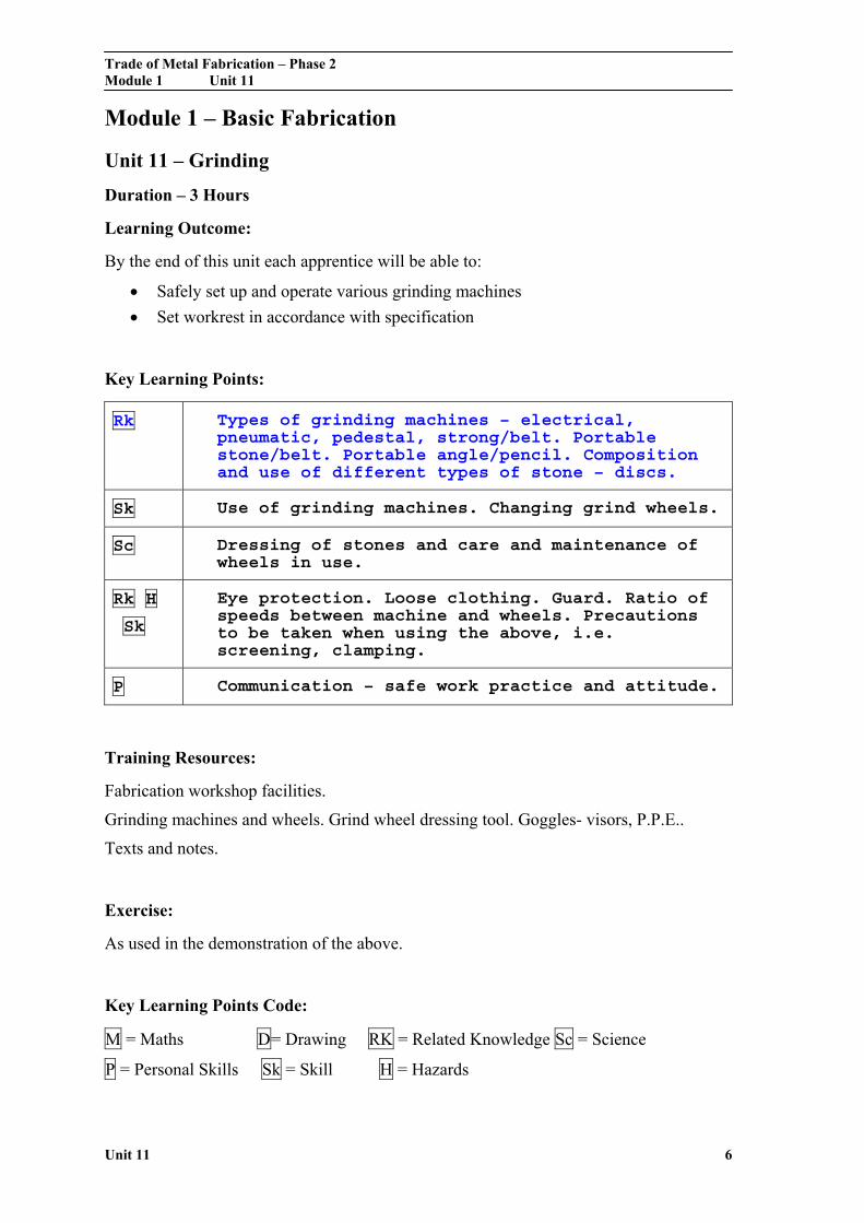
Module 1 – Basic Fabrication
Unit 11 – Grinding
Duration – 3 Hours
Learning Outcome:
By the end of this unit each apprentice will be able to:
Safely set up and operate various grinding machines
Set workrest in accordance with specification
Key Learning Points:
Rk Types of grinding machines – electrical, pneumatic, pedestal, strong/belt. Portable stone/belt. Portable angle/pencil. Composition and use of different types of stone – discs.
Sk Use of grinding machines. Changing grind wheels.
Sc Dressing of stones and care and maintenance of wheels in use.
Rk H
Sk
Eye protection. Loose clothing. Guard. Ratio of speeds between machine and wheels. Precautions to be taken when using the above, i.e. screening, clamping.
P Communication – safe work practice and attitude.
Training Resources:
Fabrication workshop facilities.
Grinding machines and wheels. Grind wheel dressing tool. Goggles- visors, P.P.E..
Texts and notes.
Exercise:
As used in the demonstration of the above.
Key Learning Points Code:
M = Maths D= Drawing RK = Related Knowledge Sc = Science
P = Personal Skills Sk = Skill H = Hazards

Trade of Metal Fabrication – Phase 2 Module 1 Unit 11
Unit 11 7
The Wheel
Due to the nature of its construction the wheel can, if not carefully treated, crack or shatter during use. To reduce the dangers of flying particles causing injury the wheel must be guarded with only the work area exposed. Examine the wheel frequently for cracks or other defects.
When grinding, move the work from side to side to avoid cutting grooves in the wheel. Use the front of the wheel as much as possible. If the side of the wheel is used, avoid using too much force.
Wheel Inspection
Vitrified bond wheels can be checked with a procedure called the ring test:
Tap the wheel with a non-metal object
If the wheel is in good condition it will ring clearly
Damaged wheels give a dull or chattering sound
Trade of Metal Fabrication – Phase 2 Module 1 Unit 11
Unit 11 8
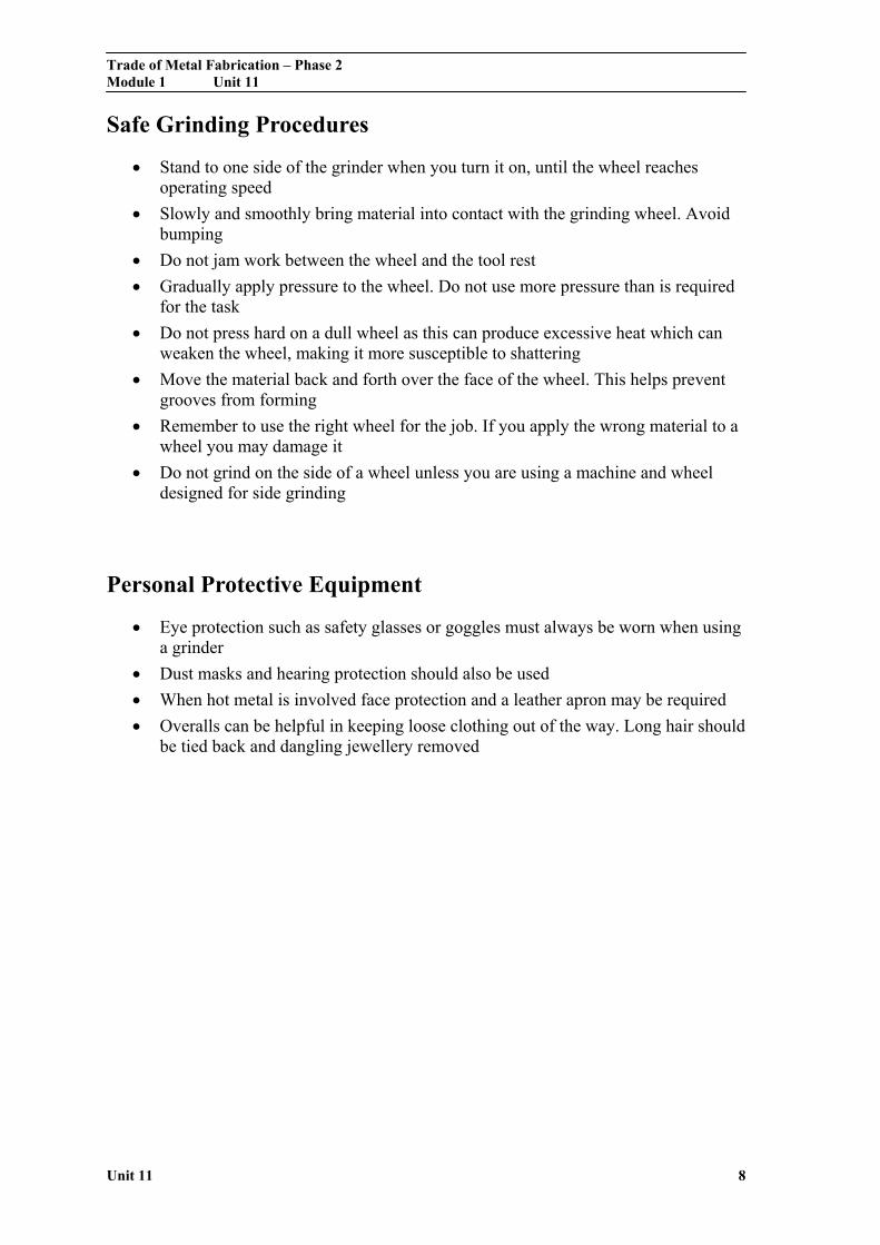
Safe Grinding Procedures
Stand to one side of the grinder when you turn it on, until the wheel reaches operating speed
Slowly and smoothly bring material into contact with the grinding wheel. Avoid bumping
Do not jam work between the wheel and the tool rest
Gradually apply pressure to the wheel. Do not use more pressure than is required for the task
Do not press hard on a dull wheel as this can produce excessive heat which can weaken the wheel, making it more susceptible to shattering
Move the material back and forth over the face of the wheel. This helps prevent grooves from forming
Remember to use the right wheel for the job. If you apply the wrong material to a wheel you may damage it
Do not grind on the side of a wheel unless you are using a machine and wheel designed for side grinding
Personal Protective Equipment
Eye protection such as safety glasses or goggles must always be worn when using a grinder
Dust masks and hearing protection should also be used
When hot metal is involved face protection and a leather apron may be required
Overalls can be helpful in keeping loose clothing out of the way. Long hair should be tied back and dangling jewellery removed

Trade of Metal Fabrication – Phase 2 Module 1 Unit 11
Unit 11 9
The Abrasive Wheel
The abrasive wheel or grinding wheel consists of two constituents:
1. The abrasive that does the cutting.
2. The bond that holds the abrasive particles together.
The specification of a grinding wheel gives a clue as to its construction and suitability for a particular operation. For example a wheel carrying the marking:
38A60-J5VBE
would indicate that the wheel has an aluminium oxide abrasive; that the abrasive grit is medium to fine in grain size; that the grade is soft; that the structure shows medium spacing; that a vitrified bond is used. How the code marked on the wheel can indicate all this information required in selecting the correct wheel for a particular job will now be examined in some detail.
Manufacturer’s Type Code
BS Code Abrasive Application
- A Aluminium oxide A high strength b i f h d
32 A Aluminium oxide Cool; fast cutting, f id t k
38 A Aluminium oxide Light grinding of h d t l
19 A Aluminium oxide A milder abrasive th 38A d f
37 C Silicon carbide For hard, brittle t i l f hi h
39 C Silicon carbide ( )
For hard, brittle t i l h
Table 1 - Manufacturer's Type Code
Trade of Metal Fabrication – Phase 2 Module 1 Unit 11
Unit 11 10
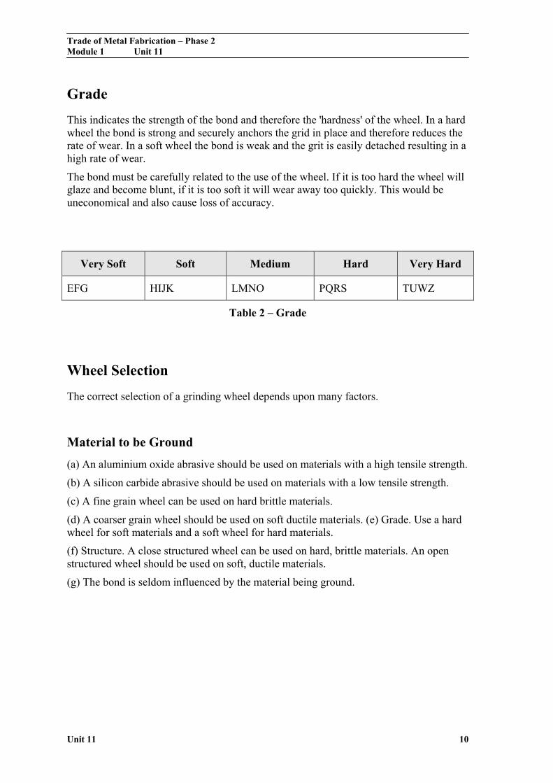
Grade
This indicates the strength of the bond and therefore the 'hardness' of the wheel. In a hard wheel the bond is strong and securely anchors the grid in place and therefore reduces the rate of wear. In a soft wheel the bond is weak and the grit is easily detached resulting in a high rate of wear.
The bond must be carefully related to the use of the wheel. If it is too hard the wheel will glaze and become blunt, if it is too soft it will wear away too quickly. This would be uneconomical and also cause loss of accuracy.
Very Soft Soft Medium Hard Very Hard
EFG HIJK LMNO PQRS TUWZ
Table 2 – Grade
Wheel Selection
The correct selection of a grinding wheel depends upon many factors.
Material to be Ground
(a) An aluminium oxide abrasive should be used on materials with a high tensile strength.
(b) A silicon carbide abrasive should be used on materials with a low tensile strength.
(c) A fine grain wheel can be used on hard brittle materials.
(d) A coarser grain wheel should be used on soft ductile materials. (e) Grade. Use a hard wheel for soft materials and a soft wheel for hard materials.
(f) Structure. A close structured wheel can be used on hard, brittle materials. An open structured wheel should be used on soft, ductile materials.
(g) The bond is seldom influenced by the material being ground.

Trade of Metal Fabrication – Phase 2 Module 1 Unit 11
Unit 11 11
Arc of Contact
(a) Figure 1 shows what is meant by 'arc of contact'.
(b) Grain size. For a small arc of contact a fine grain can be used. For a large arc of contact a coarse grain should be used.
(c) Grade. For a small arc of contact a 'hard' wheel can be used. For a large arc of contact a 'soft' wheel should be used.
(d) Structure. For a small arc of contact a close grained wheel can be used. For a large arc of contact an open structured wheel should be used.
Figure 1 - Arc of Contact

Trade of Metal Fabrication – Phase 2 Module 1 Unit 11
Unit 11 12
Type of Grinding Machine
A heavy, rigidly constructed machine can produce accurate work using softer grade wheels. This reduces the possibility of 'burning' the workpiece.
Process
As well as being used for tool sharpening and precision grinding, the abrasive wheel is also used for the following processes:
(a) Dressing the weld and grinding the weld bead flush.
(b) Edge preparation.
(c) Cutting off awkward sections.
Abrasive wheels used for these purposes are subject to far more abuse than those used for precision grinding. They are also required to remove metal more quickly, but they do not have to leave such a good finish or work so accurately as precision grinding wheels.
Cutting Off
A suitable cutting-off wheel for mild steel would be:
A 24 Q 8 B or R
Figure 2 - Abrasive Wheel Cutting-Off Machine
Trade of Metal Fabrication – Phase 2 Module 1 Unit 11
Unit 11 13
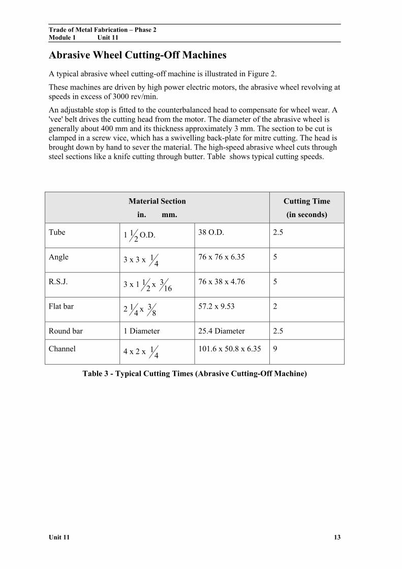
Abrasive Wheel Cutting-Off Machines
A typical abrasive wheel cutting-off machine is illustrated in Figure 2.
These machines are driven by high power electric motors, the abrasive wheel revolving at speeds in excess of 3000 rev/min.
An adjustable stop is fitted to the counterbalanced head to compensate for wheel wear. A 'vee' belt drives the cutting head from the motor. The diameter of the abrasive wheel is generally about 400 mm and its thickness approximately 3 mm. The section to be cut is clamped in a screw vice, which has a swivelling back-plate for mitre cutting. The head is brought down by hand to sever the material. The high-speed abrasive wheel cuts through steel sections like a knife cutting through butter. Table shows typical cutting speeds.
Material Section
in. mm.
Cutting Time
(in seconds)
Tube 1 21 O.D. 38 O.D. 2.5
Angle 3 x 3 x 41 76 x 76 x 6.35 5
R.S.J. 3 x 1 21 x 16
3 76 x 38 x 4.76 5
Flat bar 2 41 x 8
3 57.2 x 9.53 2
Round bar 1 Diameter 25.4 Diameter 2.5
Channel 4 x 2 x 41 101.6 x 50.8 x 6.35 9
Table 3 - Typical Cutting Times (Abrasive Cutting-Off Machine)
Trade of Metal Fabrication – Phase 2 Module 1 Unit 11
Unit 11 14
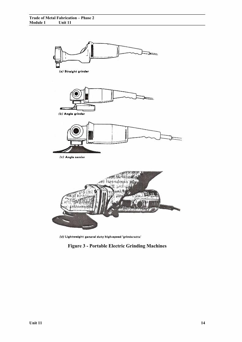
Figure 3 - Portable Electric Grinding Machines
Trade of Metal Fabrication – Phase 2 Module 1 Unit 11
Unit 11 15
Portable Grinding Machines
Portable grinding machines are often used for smoothing down welded joints and seams and generally do much of the fabrication workshop jobs which would otherwise be done by the laborious methods of chiselling and filing.
These portable tools are basically of two types, ELECTRIC and PNEUMATIC, and the three most commonly used variations of portable grinders are:
1. THE STRAIGHT GRINDER
2. THE ANGLE GRINDER
3. THE SANDER GRINDER
Figure 3 and Figure 4 illustrates electrically-powered portable grinders. Figure 3(a) shows a 'straight' portable grinder. This uses an ordinary grinding wheel, cutting on its periphery as in tool grinding.
Usually two sizes are available:
1. Grinding wheel diameter 102 mm Grinding wheel thickness 19 mm Spindle speed (running light) 8400 rev/min
2. Grinding wheel diameter 127 mm Grinding wheel thickness 19 mm Spindle speed (running light) 6600 rev/min
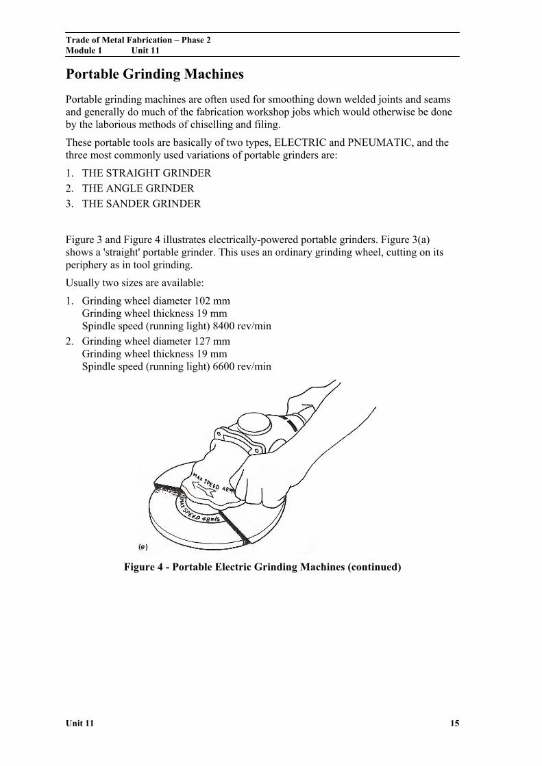
Figure 4 - Portable Electric Grinding Machines (continued)
Trade of Metal Fabrication – Phase 2 Module 1 Unit 11
Unit 11 16
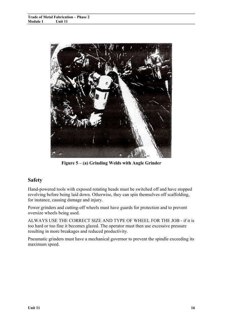
Figure 5 – (a) Grinding Welds with Angle Grinder
Safety
Hand-powered tools with exposed rotating heads must be switched off and have stopped revolving before being laid down. Otherwise, they can spin themselves off scaffolding, for instance, causing damage and injury.
Power grinders and cutting-off wheels must have guards for protection and to prevent oversize wheels being used.
ALWAYS USE THE CORRECT SIZE AND TYPE OF WHEEL FOR THE JOB - if it is too hard or too fine it becomes glazed. The operator must then use excessive pressure resulting in more breakages and reduced productivity.
Pneumatic grinders must have a mechanical governor to prevent the spindle exceeding its maximum speed.
Trade of Metal Fabrication – Phase 2 Module 1 Unit 11
Unit 11 17
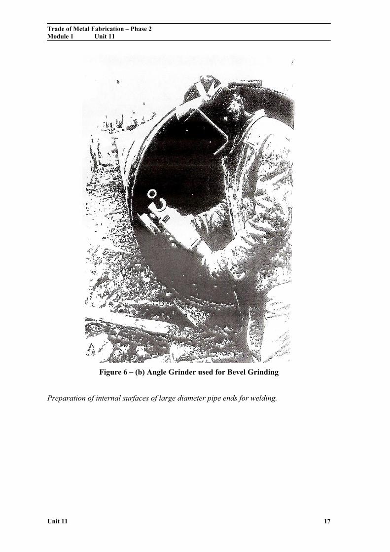
Figure 6 – (b) Angle Grinder used for Bevel Grinding
Preparation of internal surfaces of large diameter pipe ends for welding.

Trade of Metal Fabrication – Phase 2 Module 1 Unit 11
Unit 11 18
Figure 7 - (c) Grinding Edges of Flame-Cut Apertures with a Straight Grinder
Figure 8 - (d) Use of Portable Sander for Metal Surface Finishing
Trade of Metal Fabrication – Phase 2 Module 1 Unit 11
Unit 11 19
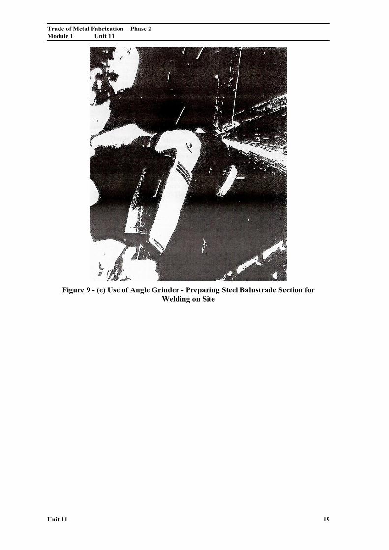
Figure 9 - (e) Use of Angle Grinder - Preparing Steel Balustrade Section for Welding on Site
Trade of Metal Fabrication – Phase 2 Module 1 Unit 11
Unit 11 20
Self Assessment
Questions on Background Notes – Module 1.Unit 11
1. Draw a Circle 60mm in Diameter.
Clearly show the following:
a. SECTOR
b. TANGENT (Shown by a line that is Tangential to Circle)
c. RADIUS
d. DIAMETER
2. Construct an angle of 45° using a Compass and Rule, clearly show the
intersecting arc’s.

Trade of Metal Fabrication – Phase 2 Module 1 Unit 11
Unit 11 21
3. What are Templates? Give three useful pieces of information on them.
Trade of Metal Fabrication – Phase 2 Module 1 Unit 11
Unit 11 22
Answers to Questions 1-3. Module 1.Unit 11
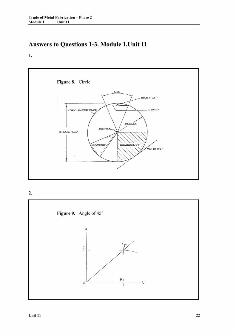
1.
Figure 8. Circle
2.
Figure 9. Angle of 45°
Trade of Metal Fabrication – Phase 2 Module 1 Unit 11
Unit 11 23
3.
Templates:
Templates are used to avoid repetitive measuring and
marking-off of the dimensions, where a number of identical
parts are required. They can also act as a guide for a cutting
process or as a simple means of checking an angle, bend or
curve. Templates can be made from Cardboard, Aluminium
Timber, Perspex and so on. Typical information found on them
would be a job or contact number, size and thickness of the plate
drilling requirements, left hand or right hand section.
Trade of Metal Fabrication – Phase 2 Module 1 Unit 11
Unit 11 24
Index
A Abrasive Wheel Cutting-Off Machines, 13
C Cutting Off, 12
G Grade, 10
P Personal Protective Equipment, 8 Portable Grinding Machines, 15
Safety, 16
S Safe Grinding Procedures, 8
T The Abrasive Wheel, 9 The Wheel, 7
W Wheel Inspection, 7 Wheel Selection, 10
Arc of Contact, 11 Material to be Ground, 10 Process, 12 Type of Grinding Machine, 12