Trade Analysis and Requirements Review - MIT OpenCourseWare · The purpose of the TARR is explicit...
133
MIT Aero/Astro EMF EMF EMF 2 2 ORCE ORCE ORCE Trade Analysis and Requirements Review <BAB> Welcome to the Trade Analysis and Requirements Review for Project EMFFORCE (ElectroMagnetic Formation Flight Of Rotating Clustered Entities). 1
Transcript of Trade Analysis and Requirements Review - MIT OpenCourseWare · The purpose of the TARR is explicit...

MIT Aero/Astro EMFEMFEMF222ORCEORCEORCE
Trade Analysis and
Requirements Review
<BAB>
Welcome to the Trade Analysis and Requirements Review for Project EMFFORCE (ElectroMagnetic Formation
Flight Of Rotating Clustered Entities).
1

ElectroMagnetic Formation Flight Of Rotating Clustered Entities 2
MIT Aero/Astro EMFEMFEMF222ORCEORCEORCE
CDIO Space Systems Product
Development
REQUIREMENTS PROCESSES
Oscar Murillo Andre Bosch
Leah Soffer William Fournier
Maggie Sullivan Erik Stockham
Jennifer Underwood
ARCHITECTURE
Jesus Bolivar DATABASES
Darien Crane Amilio Aviles
Geeta Gupta Amy Schonsheck
Timothy Sutherland Stephanie Slowik
Lindsey Wolf Melanie Woo
Introduction
Requirements
System Trades
Subsystems
Processes
Conclusion
<BAB>
The CDIO Space Systems Product Development Class met as a team for the first time five weeks ago. At this
meeting we were presented with the challenge of demonstrating the feasibility of using electromagnetic control
for formation flight of satellites. Since then the team has been working diligently to understand the problem and
quantify any relevant requirements and trades. To this end, the class organized it self into the following groups:
Requirements, Processes, Architecture, and Databases. The Requirements team was formed to identify all
customer requirements and constraints and to levy other pertinent requirements as dictated by the nature of the
project. The Processes team was formed to act as a systems engineering team so as to coordinate the other
teams. In addition, the processes team set up the processes by which the class would conduct the remainder of
the project. The Architecture team was formed to quantify the design trades in order to identify important
metrics. In the process of doing so, the Architecture team also drafted design possibilities and investigated these
possibilities. The Databases team was formed to construct a database of possible parts and manufacturers. This
database will become invaluable in determining whether to make or buy a particular part. This database will
also enable the project team to select parts that meet requirements. Once the TARR has passed, the class will be
divided into subsystem groups with a systems group coordinating the project.
2

MIT Aero/Astro EMFEMFEMF222ORCEORCEORCE
Erik Stockham
Introduction •Purpose
•Background
•Motivation
•Mission
•Approach
•Overview
Requirements
System Trades
Subsystems
Processes
Conclusion
Introduction
<JEU>
Welcome to the Introduction portion of the Trade Analysis and Requirements Review for Project EMFFORCE
(ElectroMagnetic Formation Flight Of Rotating Clustered Entities).
3

ElectroMagnetic Formation Flight Of Rotating Clustered Entities 4
MIT Aero/Astro EMFEMFEMF222ORCEORCEORCE
TARR Purpose
• Formally accept Requirements
Document
• Present system and subsystem trade
analyses
• Outside expert review of current
progress
– Provide impetus for generation of new
action items
Introduction •Purpose
•Background
•Motivation
•Mission
•Approach
•Overview
Requirements
System Trades
Subsystems
Processes
Conclusion
<BAB>
The purpose of the TARR is explicit in its name, Trade Analysis and Requirements Review. Specifically, the
class hopes to review the requirements that have been levied and the trade analyses that have been conducted.
The purpose of presenting this to an audience is twofold:
1. To require the class to polish their work by having to make it presentable to an outside
audience.
2. To seek outside view of our work as it stands.
The class realizes that we do not have all the answers and hopes that through this exercise we will gain further
understanding and new insight into the project.
4

ElectroMagnetic Formation Flight Of Rotating Clustered Entities 5
MIT Aero/Astro EMFEMFEMF222ORCEORCEORCE
Formation Flying Satellites
Introduction •Purpose
•Background
•Motivation
•Mission
•Approach
•Overview
Requirements
System Trades
Subsystems
Processes
Conclusion
• Use of a cluster of satellites flying in
formation
• New mission capabilities
• SPHERES demonstrated feasibility
<BAB & ESS & WDF>
Formation flight of satellites is defined as the use of a cluster of satellites maintaining a designated formation in
Space Flight. Although formation flight of satellites has yet to be used in practice it is being discussed in the
aerospace industry as a way to provide new mission capabilities for satellites. SPHERES demonstrated the initial
feasibility of the use of a group of satellites in formation flight and we hope to expand on this research with our
project.
5

ElectroMagnetic Formation Flight Of Rotating Clustered Entities 6
MIT Aero/Astro EMFEMFEMF222ORCEORCEORCE
Electromagnetic Control
Introduction •Purpose
•Background
•Motivation
•Mission
•Approach
•Overview
Requirements
System Trades
Subsystems
Processes
Conclusion
• The use of electromagnets as the force
generator that will control the vehicles
• Control achieved by varying the
current in the coil of the magnet
BAB
Electromagnetic control of satellites essentially means that we will be using electromagnets as the force
generators to control the relative position, attitude, and angular rate of a cluster of satellites. This control can be
achieved by varying the current in the coil of an electromagnet to vary the B field the electromagnets provide.
6

ElectroMagnetic Formation Flight Of Rotating Clustered Entities 7
MIT Aero/Astro EMFEMFEMF222ORCEORCEORCE
Advantages of Formation
Flying Satellites
• Smaller vehicles
– Cheaper to launch
• Redundancy
– Mission doesn’t fail if one fails
• Reconfigurable
– Can tailor for mission specs
Introduction •Purpose
•Background
•Motivation
•Mission
•Approach
•Overview
Requirements
System Trades
Subsystems
Processes
Conclusion
BAB
A number of current satellite missions are considering multiple spacecraft architectures for a variety of reasons.
First, multiple spacecraft can be separated to large baselines thereby improving angular resolution for imaging,
astrometry, and planet detection. Second, each spacecraft in the formation can be smaller than a single spacecraft
designed to perform the same mission and thereby provide easier packaging, launch, and deployment. Third,
since inter-spacecraft interfaces are soft (e.g., communications, optics, control, metrology), if a spacecraft fails,
it can easily be removed from the formation and replaced with a functioning spacecraft. Fourth, as technology
improves, replacement spacecraft can be launched and integrated into the array thereby evolving the formation’s
capabilities without the costly “block changes” typical of past programs. (Miller, D. et. al., EMFF for Sparse
Aperture Telescopes)
7

ElectroMagnetic Formation Flight Of Rotating Clustered Entities 8
MIT Aero/Astro EMFEMFEMF222ORCEORCEORCE
Applications of Formation
Flying Satellites
• Interferometry
– Increased resolution
• Servicing
• Upgrade and maintenance
• Deployment and system assembly
• Large and reconfigurable apertures
Introduction •Purpose
•Background
•Motivation
•Mission
•Approach
•Overview
Requirements
System Trades
Subsystems
Processes
Conclusion
BAB
One of the main arguments for utilizing satellite formation flight for surveillance and imaging applications is the
fact that large sensor apertures can be synthesized without the need for correspondingly large physical
structures. In the case of interferometry, larger apertures lead to higher resolution. But other advantages to
formation flight are equally compelling: these include the possibility of dynamically changing the formation
geometry to respond to evolving mission sensing requirements or to address multiple missions, and the
capability of replacing failed formation elements on orbit more efficiently and economically than heretofore.
(from NRO proposal)
8

ElectroMagnetic Formation Flight Of Rotating Clustered Entities 9
MIT Aero/Astro EMFEMFEMF222ORCEORCEORCE
Challenges of Current Formation
Flying Satellite Technology
• Command and control
– Must control multiple vehicles’ inertial
position and motion
• Drawbacks of propellant for ACS
– Consumable fuel limits endurance
– Gas plumes contaminate IR and other
imaging instruments
– Ion plumes potentially contaminate
sensitive equipment
Introduction •Purpose
•Background
•Motivation
•Mission
•Approach
•Overview
Requirements
System Trades
Subsystems
Processes
Conclusion
BAB
While these benefits are clear, there are several drawbacks. As one explores the design of these systems in more
depth, one recognizes that there is a miss-match between the geometric requirements that the formation must
achieve and the way in which that geometry is controlled. Specifically, the relative separations between
spacecraft, not the absolute inertial position in space, is important. However, thrusters actuate inertial degrees-
of-freedom. In addition, precision formation flight of the satellites in the array requires that precious propellant
be expended to maintain the formation geometry. This has several implications. First, propellant is a consumable
which, once depleted, renders the satellite useless. Second, the impingement of a thruster plume on a
neighboring spacecraft can cause a dynamic disturbance to its stability, deposit particulates on sensitive optics,
induce inadvertent charging, and actually ablate material off the spacecraft thereby causing permanent damage.
Third, for missions such as NASA’s Terrestrial Planet Finder (TPF), the propellant plume can put a thermally
bright haze across the line-of-sight of the telescope. For example, micron particles at room temperature can blind
TPF even if the particles are many kilometers away. Furthermore, low speed plume exhaust will tend to be
attracted to the spacecraft creating a local pollution haze through which the telescope must look. (adapted from
Big Sky presentation)
9

ElectroMagnetic Formation Flight Of Rotating Clustered Entities 10
MIT Aero/Astro EMFEMFEMF222ORCEORCEORCE
Advantages of Electromagnetic
Formation Flight
• Proposed Electromagnetic Control
– No thrusters
• Energy comes from Solar arrays
• Longer life (fewer/no consumables)
• No contamination of IR imaging
• No damaging plume
– Relative position/motion vs. inertial
position/motion
Introduction •Purpose
•Background
•Motivation
•Mission
•Approach
•Overview
Requirements
System Trades
Subsystems
Processes
Conclusion
BAB
To overcome some of the difficulties of current FF technology, the use of electromagnets for formation control
has been suggested. Research has been conducted into the control models of such a system by the MIT Space
Systems Laboratory (SSL).
As earlier discussed, one of the undesirable aspects of formation flight is the use of thrusters. EMFF would
eliminate the use of thrusters for position in the formation. This would lead to longer life, no contamination of
IR imaging, and no damaging plume. In addition EMFF would lead to better control of the formation.
Specifically electromagnets control relative position instead of inertial position and it is this relative positioning
capacity that we seek.
10
ElectroMagnetic Formation Flight Of Rotating Clustered Entities 11
MIT Aero/Astro EMFEMFEMF222ORCEORCEORCE
Design Challenges of EMFF
• Control Problem
– Unstable system
– Rotating system
– Distributed • Moving one vehicle affects all vehicles
• Disadvantages of Electromagnets
– Heavy
– Weak • Force drops off as fourth power of
separation distance
Introduction •Purpose
•Background
•Motivation
•Mission
•Approach
•Overview
Requirements
System Trades
Subsystems
Processes
Conclusion
ESS & BAB
There are also challenges with using Electromagnets for control of Formation flight. The first of which, is that it
has never been done before. The problem of controlling satellites using electromagnets is also formidable. The
details of the electromagnetic effects with multiple poles in multiple planes gets exponentially complicated with
the number of satellites and degrees of freedom that need to be controlled. The system is inherently unstable and
has the added difficulty that the control of each satellite is coupled with the motions of every other satellite in
the constellation. Electromagnets are also very heavy and have a force which drops off proportional to the
separation distance to the fourth.
11

ElectroMagnetic Formation Flight Of Rotating Clustered Entities 12
MIT Aero/Astro EMFEMFEMF222ORCEORCEORCE
EMFF Mission Statement
• To determine the feasibility of
electromagnetic control of formation
flying satellites.
Introduction •Purpose
•Background
•Motivation
•Mission
•Approach
•Overview
Requirements
System Trades
Subsystems
Processes
Conclusion
2r
ESS & BAB
This is the mission statement for our project. It will be fully explained in the Requirements Document and in the
requirements section of this Review.
12

ElectroMagnetic Formation Flight Of Rotating Clustered Entities 13
MIT Aero/Astro EMFEMFEMF222ORCEORCEORCE
CDIO Program Approach
• Conceive and Design EMF2 testbed in
Spring 2002
• Implement testbed in Fall 2002
• Operate completed testbed in Spring
2003
– small flat surface at MIT
– Large smooth floor test facility in Denver
Introduction •Purpose
•Background
•Motivation
•Mission
•Approach
•Overview
Requirements
System Trades
Subsystems
Processes
Conclusion
ESS & BAB
In order to achieve our mission, there are several steps we must progress through. The first stage of the project
will be the conception and design of the EMF2ORCE testbed in the spring of 2002. The design will be finalized
in the fall of 2002 and construction and testing of subsystems will occur. In Spring of 2003, the subsystems will
be integrated into the final system and tested first at MIT and then at the Lockheed Martin flat floor test facility
in Denver, Colorado.
13

ElectroMagnetic Formation Flight Of Rotating Clustered Entities 14
MIT Aero/Astro EMFEMFEMF222ORCEORCEORCE
TARR Overview
• Requirements
• System-level trades analysis
– Driving mathematics of EMFF
• Subsystem trades analysis
– Product specifications
• CDIO processes
– Methodologies
– Plan for project completion
Introduction •Purpose
•Background
•Motivation
•Mission
•Approach
•Overview
Requirements
System Trades
Subsystems
Processes
Conclusion
ESS & BAB
The outline for today’s presentation will include a discussion of the system’s requirements by the Requirements
team. Followed by a discussion of the large scale system level trade analysis and equations presented by the
Architecture team. We will then go into the trade analysis at the subsystem level provided by a combination of
the Architecture and Databasing Teams. Finally, the Processes team will explain the procedures that will be used
by the class to ensure the successful completion of this project. We will follow the presentation with a question
and answer session.
14

MIT Aero/Astro EMFEMFEMF222ORCEORCEORCE
Requirements Review
Maggie Sullivan
Leah Soffer
Introduction
Requirements •Introduction
•Customer Req
•Mission
•Constraints
•System
•Subsystem
•Guidelines
System Trades
Subsystems
Processes
Conclusion
BAB, JEU
Welcome to the Requirements Review portion of the Trade Analysis and Requirements Review for Project
EMFFORCE (ElectroMagnetic Formation Flight Of Rotating Clustered Entities).
15

ElectroMagnetic Formation Flight Of Rotating Clustered Entities 16
MIT Aero/Astro EMFEMFEMF222ORCEORCEORCE
Requirements Introduction
• Customer Requirements
• Mission Statement
• Constraints on the Problem
• System Requirements
– Functional and operational
• Subsystem Requirements
– Functional and operational
• Additional Notes
Introduction
Requirements •Introduction
•Customer Req
•Mission
•Constraints
•System
•Subsystem
•Guidelines
System Trades
Subsystems
Processes
Conclusion
MS
The Requirements Team presentation is primarily the Requirements Document mapped onto slides and detailed
for the audience.
Each requirement in this presentation is referenced to the Document and, where applicable, to one or more Customer-originated documents.
There are a few points recommended by the customer proposals and by the staff that are not requirements but guidelines, and recommendations for design approaches. These are noted at the end of the Requirements presentation as a springboard for the top-level system trade analysis.
16

ElectroMagnetic Formation Flight Of Rotating Clustered Entities 17
MIT Aero/Astro EMFEMFEMF222ORCEORCEORCE
System Representation
• Multiple vehicles
• Formation flying maneuvers
representative of real-world
applications
– Dynamically changing geometry
– Replacement elements
• Electromagnetic control testing
Introduction
Requirements •Introduction
•Customer Req
•Mission
•Constraints
•System
•Subsystem
•Guidelines
System Trades
Subsystems
Processes
Conclusion
MS
The primary sources of Customer Requirements are the Executive Summary EMFF Proposal by MIT SSL
(hereafter referred to as E-S), and the Technical-Management Proposal by MIT Space Systems Laboratory (MIT
SSL) and Lockheed-Martin Advanced Technology Center (LM-ATC) (hereafter referred to as T-M). Both
documents are in response to National Reconnaissance Office (NRO) document 000-02-R-0008. (The NRO is
the source of funding for the project.)
•Multiple Vehicles (T-M, page 4, col. 2b): “This testbed will consist of small prototype satellites, …”
(EMF2ORCE Requirements Document [RD] 2.1)
•Representative Formation Flying Maneuvers:
•“… these [advantages to formation flight] include … dynamically changing the formation
geometry to respond to evolving mission sensing requirements or to address multiple missions,” (E-S,
p.1, col. 1a) [RD 2.2.1].
•“… the capability of replacing failed formation elements on orbit…” (E-S, p.1, col. 1a) [RD 2.2.2].
•Electromagnetic Control Testing: there are several aspects of EM control which the EMF2ORCE project must
address [RD 2.3].
17

ElectroMagnetic Formation Flight Of Rotating Clustered Entities 18
MIT Aero/Astro EMFEMFEMF222ORCEORCEORCE
EM Control Testing
• Replace thrusters
• Control 3 degrees of freedom (DOF),
translate to 6 DOF
• Robust controller
– Disturbance rejection
– Reposition vehicles
– Restoring forces
Introduction
Requirements •Introduction
•Customer Req
•Mission
•Constraints
•System
•Subsystem
•Guidelines
System Trades
Subsystems
Processes
Conclusion
MS
•Replace thrusters: “The EMFF system would replace the traditional thrusters in maintaining the geometry of the
formation in space or in evolving it in response to changing surveillance requirements,” (E-S, p.1, col. 1a) [RD
2.3.1]
•Degrees of Freedom (DOF): “As part of the EMFF program, this class will design, build, test, and operate a
testbed that will allow for three and six DOF EMFF,” (T-M, p.4, col. 1a) [RD 2.3.2]. The class interpretation of
this statement is as follows
•The system shall operate in two dimensions.
•Each individual vehicle shall have three controlled DOF: two of translation and one of rotation (X,
Y, ).
•The system shall control all relative DOF. The six possible DOF for two vehicles are as follows:
linear separation distance, “skew” separation, direct translation of the formation, rotation of each
individual vehicle, and rotation of the formation. However, since the forces in an EMFF system are all
internal to the system, the formation cannot translate its own center of mass. Therefore, our System
Functional Requirements will show that EMF2ORCE shall control all relative system DOF.
•Since the applications of this system involve space-based satellites, eventually the idea will be
implemented in a three-dimensional environment. Therefore, EMF2ORCE shall show potential for
translation to control six individual DOF (in 3-D: X, Y, Z, , , ).
•The system shall have a robust control design and implementation that provides for the following:
•Disturbance rejection: “… design that will have the capability to counteract any disturbance force
that the satellite formation will encounter…” (T-M, p.1, col. 2b) [RD 2.3.3.1]
•Vehicle repositioning: “have enough control authority to reposition satellites within the formation”
(T-M, p.1, col. 2b) [RD 2.3.3.2]
•Restoring forces: “… using magnets to generate the necessary restoring forces [to remain stable
for a sufficiently long time],” (E-S, p.1, col. 1b) [RD 2.3.3.3]
Large-scale concerns such as the effect of the Earth’s magnetic field or valid orbital metrology techniques are
not addressed by EMF2ORCE. These points are outside the scope of our project; they will be tackled by the
MIT SSL and LM-ATC.
18

ElectroMagnetic Formation Flight Of Rotating Clustered Entities 19
MIT Aero/Astro EMFEMFEMF222ORCEORCEORCE
Mission Statement
Demonstrate the feasibility of
electromagnetic control for formation
flying satellites.
• Demonstrate
• Feasibility
• Electromagnetic
• Formation Flying
Introduction
Requirements •Introduction
•Customer Req
•Mission
•Constraints
•System
•Subsystem
•Guidelines
System Trades
Subsystems
Processes
Conclusion
LS
This is the objective of our project as created to fulfill the customer requirements.
19

ElectroMagnetic Formation Flight Of Rotating Clustered Entities 20
MIT Aero/Astro EMFEMFEMF222ORCEORCEORCE
Mission Statement - Demonstrate
• Demonstrate implies operating an
electromagnetic formation flight testbed
in a scaled mode representative of a real
world application.
– Shall operate in 2D
– Shall be easily translated to 3D
environment
Introduction
Requirements •Introduction
•Customer Req
•Mission
•Constraints
•System
•Subsystem
•Guidelines
System Trades
Subsystems
Processes
Conclusion
LS
This part of the mission statement stems from the customer requirements that the system should perform
representative formation flying maneuvers [2.2], and be composed of vehicles that control three individual
degrees of freedom (DoF) in EMFF (X, Y, ) and demonstrate potential for translation to 6 individual DoF (X,
Y, Z, , , [2.3.2]
•The testbed will be operated in a 2D flat floor facility. [3.1.1]
•The design should easily be extended to 3D and 6 degrees of freedom, but it is not required to be demonstrated
by this project. [3.1.2]
20

ElectroMagnetic Formation Flight Of Rotating Clustered Entities 21
MIT Aero/Astro EMFEMFEMF222ORCEORCEORCE
Mission Statement - Feasibility
• Feasibility implies that the project is
limited by the ability to design a
functional controller and the constraints
levied on the class.
– Control system shall be designed to
stabilize system
– Budget and schedule limitations
Introduction
Requirements •Introduction
•Customer Req
•Mission
•Constraints
•System
•Subsystem
•Guidelines
System Trades
Subsystems
Processes
Conclusion
LS
•This stems from customer requirement 2.3, stating the system should facilitate testing and verification of
electromagnetic control. The presence of electromagnets in a rotating system present the potential for instability.
In this project, it must be proven that the system can be stabilized by using electromagnets to control the
formations. [3.2.1]
•This stems from the schedule constrain [4.1], and budget constraint [4.2]. Though the use of electromagnetic
control may be possible, it must be researched and implemented within 15 months and within the set budget.
[3.2.2]
21

ElectroMagnetic Formation Flight Of Rotating Clustered Entities 22
MIT Aero/Astro EMFEMFEMF222ORCEORCEORCE
Mission Statement - EM Control
• Electromagnetic control implies the
design and implementation of a controller
using:
– No thrusters
– Angular momentum storage
Introduction
Requirements •Introduction
•Customer Req
•Mission
•Constraints
•System
•Subsystem
•Guidelines
System Trades
Subsystems
Processes
Conclusion
LS
This part of the mission statement comes from the customer requirement that the system must implement an
electromagnetic control system to replace traditional thrusters. [2.3.1]
•Because this project is exploring an alternate method of control, thrusters may not be used at all. [3.3.1]
•Angular momentum must be used in conjunction with the electromagnets to create motion. [3.3.2]
22

ElectroMagnetic Formation Flight Of Rotating Clustered Entities 23
MIT Aero/Astro EMFEMFEMF222ORCEORCEORCE
Mission Statement - FF Satellites
• Formation flying satellites implies a
testbed composed of multiple rigid
bodies that must exhibit the functionality
of a real cluster of satellites in formation
flight.
– Shall sense other vehicles
– Shall implement user commands
– Shall maintain degree of autonomy
Introduction
Requirements •Introduction
•Customer Req
•Mission
•Constraints
•System
•Subsystem
•Guidelines
System Trades
Subsystems
Processes
Conclusion
LS
This part of the mission statement comes from the customer requirements to perform representative formation
flying maneuvers [2.2], and utilize a robust controller [2.3.3]
•The vehicles must determine their own relative position and communicate it to the other vehicles [3.4.1]
•A ground station will send commands to the formation. [3.4.2]
•The system must maintain a minimal degree of autonomy by successfully carrying out preprogrammed test
plans without user intervention. [3.4.3]
23

ElectroMagnetic Formation Flight Of Rotating Clustered Entities 24
MIT Aero/Astro EMFEMFEMF222ORCEORCEORCE
Constraints
• Schedule
• Budget
• Human resources
• Testing facility
• Self-contained
• Recorded test data
• Safety
Introduction
Requirements •Introduction
•Customer Req
•Mission
•Constraints
•System
•Subsystem
•Guidelines
System Trades
Subsystems
Processes
Conclusion
0M/ LS/ MS
•The system must be designed, built, tested, and fully operational by May 2003. [4.1]
•There is a financial cap of $50,000. [4.2]
•The team responsible for this project includes the MIT CDIO-3 students and staff. [4.3]
•The system must operate in available test spaces. The preliminary test facility shall be a flat-floor area at MIT,
less than 10 sq. ft. The culminating system tests shall be at the Lockheed flat-floor facility in Denver, CO.
which means the system must be transportable, able to maneuver freely on the flat floor, and
within the floor dimensions of 20ft by 30 ft. [4.3]
•As a self contained vehicle, it cannot have any external unbilicals during testing for power, gas, or
communication [4.5]. The test duration shall be limited by on-board resources. [4.6]
•Test must be documented and data recorded for offline analysis and validation of customer requirements. [4.7]
•Safety must be preserved at all levels of work throughout the project timeline. [4.8] This includes individuals
involved in construction and testing must insure safety, each vehicle shall not damage other vehicles or its test
environment, and the system shall not be damaged in transport.
24

ElectroMagnetic Formation Flight Of Rotating Clustered Entities 25
MIT Aero/Astro EMFEMFEMF222ORCEORCEORCE
System Functional Requirements
Musts:
• Stability with at least three vehicles
• Control in each relative DOF
Shoulds:
• Representative 5 rotation maneuver
• Far field
Introduction
Requirements •Introduction
•Customer Req
•Mission
•Constraints
•System
•Subsystem
•Guidelines
System Trades
Subsystems
Processes
Conclusion
LS/ MS
•The system must demonstrate stable maneuverability using at least three vehicles. This requirement, [5.1.1.1]
stems from the customer requirements [2.1, 2.3.3].
•Control each relative system degree of freedom This requirement, [5.1.1.3] is derived from [2.3.2]. It implies
the system must be demonstrated in 2 dimensions with identifiable transition to 3 dimensions. Also, it cannot
control absolute motion of center of mass.
• The system should complete a representative five-rotation system maneuver as stated in [5.1.2.1] based on
customer requirement [2.2.1], This maneuver will include one rotation for spin-up from rest to a separation
distance of at least 2 meters. Then, it will complete three rotations at a constant angular rate of 6 degrees of arc
per second for a 2 meter separation distance. Finally, it will have one rotation to de-spin to rest.
•The system should operate in the far field of EM control as stated in [5.1.2.2] This stems from customer
requirements [2.2, 2.3] The “far field” interpretation implies a separation distance of at least 10 times
electromagnet length. Any different interpretation will lead to inconsistencies with the 2 meter separation
distance.
25

ElectroMagnetic Formation Flight Of Rotating Clustered Entities 26
MIT Aero/Astro EMFEMFEMF222ORCEORCEORCE
System Operational Requirements
• Test time 5 minutes
• No umbilicals
• Identical interchangeable vehicles
• Send/record test data
• Respond to other satellites
• Respond to user input
• Demonstrate autonomy
• Maintain safety
Introduction
Requirements •Introduction
•Customer Req
•Mission
•Constraints
•System
•Subsystem
•Guidelines
System Trades
Subsystems
Processes
Conclusion
LS
•The system shall operate without needing recharged batteries or gas resupply for a period of time useful to
perform several tests, as stated in [5.1.1]. This comes from the constraints [4.6, 4.7] Based on the five-rotation
maneuver, duration of a single test is 5 minutes so stability can be demonstrated, data recorded, and significant
maneuvers can be performed.
•Operate with no external umbilicals as stated in [5.2.2] from constraint [4.5] This means the power supply must
be on-board, wireless communication must be used, and all other resources (such as gas supply) must be self-
contained.
•Each vehicle must be identicle to the others in the system. This allows mission flexibility in that each vehicle
can perform any task. Also, the vehicles must be able to be replaced. Identicle vehicles allows for easy
replacement, as well as cost efficiency through standardized parts. This is requirement [5.2.3] as derived from
[2.2.2]
•Each vehicle shall record flight data including position and health. The data will be sent to a ground station for
inflight analysis, as well as recorded for later download and analysis. These are requirements [5.2.4, 5.2.5],
which come from the constraints [4.7, 4.8.2]
•The system shall respond to other satellites in formation in real time at a distance of at least 2 meters to
demonstrate far field, but no greater than 8 meters due to size of testing facility. These requirements [5.2.6,
5.2.7] come from [2.2]
•The system shall respond to user input from a ground station within 0.1 seconds as stated in [5.2.8] stemming
from [2.2]
•The system shall demonstrate a basic level of autonomy [5.2.9] The system will receive user input from a
ground station but must then executed the maneuver without further user input. It must maintain stability, reject
disturbances, and reposition the vehicles without additional user input. This requirement stems from the
customer requirement [2.2.1]
•The system must not be damaged during testing as stated in [5.2.10]. This comes from the constraints [4.8.1,
4.8.2]
26

ElectroMagnetic Formation Flight Of Rotating Clustered Entities 27
MIT Aero/Astro EMFEMFEMF222ORCEORCEORCE
Structure: Functional
• Center of mass location
• Lightweight, air carriage dependent on
vehicle weight
• Protection
• Shielding
• Standardized parts
Introduction
Requirements •Introduction
•Customer Req
•Mission
•Constraints
•System
•Subsystem
•Guidelines
System Trades
Subsystems
Processes
Conclusion
LS
•Location of center of mass of each vehicle must not destabilize moving system. It must have a low center of
mass so each vehicle is not top heavy and inclined to tip while moving. This requirement [6.1.1.1] is derived
from [5.1.1.1]
•The structure should be lightweight to minimize cost. The design of the air carriage will depend on the mass of
the vehicle. Requirement [6.1.1.2] is derived from [4.2, 4.5]
•A form of bumpers or robust structure is required to protect the vehicle from collisions within testing
environment. Requirement [6.1.1.3] is from constrain [4.8.2]
•Shielding for the onboard electronics must be provided so the force from the magnet does not interfere with the
components. Requirement [6.1.1.4] stems from constraint [4.8.2]
•The system must utilize standardized parts for interchangeability, ease of manufacturing, and ease of repair.
This requirement [6.1.1.5] stems from [5.1.1.2]
floor.
27

ElectroMagnetic Formation Flight Of Rotating Clustered Entities 28
MIT Aero/Astro EMFEMFEMF222ORCEORCEORCE
Structure: Operational
• Stable movement at specified height
• Accessible resources in under 1 minute
• Accessible subsystems for
repair/maintenance
• Ports for downloading telemetry
• No umbilicals
Introduction
Requirements •Introduction
•Customer Req
•Mission
•Constraints
•System
•Subsystem
•Guidelines
System Trades
Subsystems
Processes
Conclusion
LS
•The air carriage must support the full weight of the vehicle. The system must remain stable when it is raised
from the ground by the air carriage. The height required to be lifted is determined by the roughness of the test
space. The height must clear the degree of roughness. This requirement [6.1.2.1] is derived from [4.2.2.2,
5.1.1.1]
•The on-board power supply and gas supply must be easily accessible. It shall take less than a minute to access
the different resources so they can be replenished and renewed without wasting test time. This requirement
[6.1.2.2] stems from the constraint [4.6]
•On-board subsystems should also be located so they can be readily accessed. The computer system, sensing
system, and other subsystems should be easily accessed for repair or maintenance without disturbing other
subsystems. This is requirement [6.1.2.3] stemming from constraint [4.6]
•Each vehicle must contain ports to download health and position telemetry after test run for later analysis. This
is requirement [6.1.2.4] from constraint [4.7]
•During testing, the system may not contain umbilicals that would alter angular momentum. This suggests
onboard fuel supply, gas supply, and wireless communication. This is requirement [6.1.2.5] stemming from
[5.2.2]
28

ElectroMagnetic Formation Flight Of Rotating Clustered Entities 29
MIT Aero/Astro EMFEMFEMF222ORCEORCEORCE
Power
Functional
• One backup power supply per vehicle
• Sustain power for 30 minutes
• Have a minimum overall lifetime of 1
year
Operational
• Recharge in 30 minutes
• Self-contained
Introduction
Requirements •Introduction
•Customer Req
•Mission
•Constraints
•System
•Subsystem
•Guidelines
System Trades
Subsystems
Processes
Conclusion
OM/ LS
Functional Requirements
•Each vehicle must contain one onboard power supply and one spare. The power supplies must be chargeable
and reusable to save money. While one is being used, the other can charge. This requirement [6.2.1.1] is from
constraint [4.6]
•Each power supply must sustain power for 30 minutes. This is to allow time for multiple tests without renewing
power. This is requirement [6.2.1.2] is from [5.2.1]
•The batteries shall be usable (still able to be recharged) for at least one year, or the length of design and testing.
This requirement [6.2.1.3] is derived from the constraints [4.1, 4.2]
Operational Requirements
•The power suppy shall be recharged in 30 minutes to allow for continual testing. This is requirement [6.2.2.1] is
from constraint [4.6]
•Power supply completely contained within structure. Requirement [6.2.2.2] stemming from [5.2.2.1]
To allow the system to run freely on the testing environment the power must be internal. An untethered in-flight
power supply is necessary to simulate space-like dynamics – outside forces will affect the dynamics and stability
of individual vehicles through friction and balance.
The testing time will generally be less than 30 minutes. Spin up and Spin down times will be less than 5
minutes, and stable flight will generally last less than 5 minutes. It is desired that multiple test be run on the
same power unit.
The recharge time is set so that at no time will we be unable to perform a test because we do not have a power
unit. This is coupled with the requirement that we have 2 power units per vehicle.
The requirement of a 1 year overall life is set so that we do not have to replace the units while in our testing
phase. Our testing phase will be less than 1 year, however, power units tend to deteriorate as time progress,
resulting in a less efficient power supply. 29

ElectroMagnetic Formation Flight Of Rotating Clustered Entities 30
MIT Aero/Astro EMFEMFEMF222ORCEORCEORCE
Actuator: Functional
• Controllable in all relative DOFs – Relative position tolerance
– Angle tolerance
• Sized for far field
• Stability – Magnet response time
– Magnet location
• Infinite solenoid approximation
Introduction
Requirements •Introduction
•Customer Req
•Mission
•Constraints
•System
•Subsystem
•Guidelines
System Trades
Subsystems
Processes
Conclusion
LS
•Each vehicle shall control three degrees of freedom. In a multiple vehicle configuration, there will be many
degrees of freedom, both relative and absolute. Absolute degrees of freedom, such as translation of center of
mass of system, will be impossible. Only relative degrees of freedom will be controlled, as stated in requirement
[6.3.1.1] traced to [5.1.1.2]
•Both relative position and angle will be controlled to a certain tolerance. These are dependent on the
separation distance and the angular rotation rate. These are requirements [6.3.1.1.1, 6.3.1.1.2] with
suggested separation distances and rotation rates listed in [5.1.2.1.2]
•The size of the electromagnet determines the strength, and the ratio of the separation distance to length of
magnet determines satisfaction of the far field requirement. The electromagnet must be sized to satisfy far field
requirement. This is requirement [6.3.1.2] as derived from [5.1.2.2]
•One function of the electromagnet besides controlling motion is to induce stability This requirement [6.3.1.3],
along with the details regarding stability below, are derived from requirement [5.1.1.1]
•Responsiveness of the magnet must be sufficient to respond to small changes and maintain stability.
•The magnet location must be determined to not disturb system stability. In a moving system, the
magnet of one vehicle can create a torque on other vehicles if the magnets are not located near the
midpoint of the vehicle.
•Many equations used to model the system assume the magnet is an infinite solenoid. The magnet should
approximate an infinite solenoid for this reason and to limit fringe effect of the field lines.
30

ElectroMagnetic Formation Flight Of Rotating Clustered Entities 31
MIT Aero/Astro EMFEMFEMF222ORCEORCEORCE
Actuator: Operational
• Shield electronics from magnet
• Limit magnet weight for
maneuverability
• Size magnet for test space
Introduction
Requirements •Introduction
•Customer Req
•Mission
•Constraints
•System
•Subsystem
•Guidelines
System Trades
Subsystems
Processes
Conclusion
LS
•Shielding from the electromagnet to protect onboard electronics. This is
requirement [ 6.3.2.1] , which is derived from [6.1.1.4, 4.8.2]
•The magnet weight is limited by the weight able to be supported by carriage and
move freely on test floor. This is requirement [6.3.2.2] derived from [4.4.2.2,
6.1.1.2]
•Magnet size determines vehicle size, which is limited by test space. This
requirement [6.3.2.3] comes from [4.4]
31

ElectroMagnetic Formation Flight Of Rotating Clustered Entities 32
MIT Aero/Astro EMFEMFEMF222ORCEORCEORCE
Metrology
• Functional
– Full field of view
– Range
– Relative tolerances
• Operational
– Work with avionics to interpret data
– Robustness to withstand transport
– Budgets
Introduction
Requirements •Introduction
•Customer Req
•Mission
•Constraints
•System
•Subsystem
•Guidelines
System Trades
Subsystem
Processes
Conclusion
MS
Sources for listed requirements are referenced in brackets [x].
Functional Requirements:
• Full field of view within testing facility (360 degrees in two dimensions)
• Sensing presence of other vehicles to a distance compatible with test facilities
• Determining separation distance of other vehicles to a linear tolerance
dependent on linear controllability [6.3.1.1.1]
• Goal: sense to one-tenth the control tolerance
• Determining relative attitude (direction) of vehicle to an angular tolerance
dependent on angular controllability [6.3.1.1.2]
• Calculate angle between vehicles
• Goal: sense to one-tenth the control tolerance
• Other items: angular rate of formation, speed of relative linear motion (closing
distance)
Operational Requirements: Subsystem shall:
• Communicate with avionics to calculate positions from sensor data
• Withstand transport to remote testing facility
• Cheap enough to replace, since we don’t have the tech on-site to fix…
• Fall within all budgets regarding cost, weight, size 32

ElectroMagnetic Formation Flight Of Rotating Clustered Entities 33
MIT Aero/Astro EMFEMFEMF222ORCEORCEORCE
Avionics: Functional
• Manage subsystems
– Timing
– Memory
• Run preprogrammed test procedures
• Store test data
Introduction
Requirements •Introduction
•Customer Req
•Mission
•Constraints
•System
•Subsystem
•Guidelines
System Trades
Subsystems
Processes
Conclusion
MS
Sources for listed requirements are referenced in brackets [x].
Functional Requirements
• Coordinate timing and allocate memory among metrology, actuators, power
subsystems [5.2.1, 5.1.2.1]
•Implement preprogrammed test runs [5.2.9]
•Interpret metrology data [6.4.2.1]
•Control power to actuators [6.2]
•Store test data for later analysis [5.2.4]
33

ElectroMagnetic Formation Flight Of Rotating Clustered Entities 34
MIT Aero/Astro EMFEMFEMF222ORCEORCEORCE
Avionics: Operational
• Realtime processes
• Store health records
• Emergency memory backup
• Software operations
• Budgets
Introduction
Requirements •Introduction
•Customer Req
•Mission
•Constraints
•System
•Subsystem
•Guidelines
System Trades
Subsystems
Processes
Conclusion
MS
Sources for listed requirements are referenced in brackets [x].
Operational Requirements
•Process in realtime to represent a real-world situation [5.2.6, 5.2.8]
•Take health records for realtime reports to operators [5.2.5]
•Have emergency backup storage in case of unplanned shutdown [5.2.10]
•Run software operable by project HR [5.2.11]
•Fall within all budgets regarding cost, weight, power, size [4.2, 4.4]
34

ElectroMagnetic Formation Flight Of Rotating Clustered Entities 35
MIT Aero/Astro EMFEMFEMF222ORCEORCEORCE
Communication: Functional
• Vehicle-vehicle
– Metrology and control
• Ground-vehicle
– Test initiation
– Emergency intervention
• Vehicle-ground
– Selected health and test data
• Self-contained system
Introduction
Requirements •Introduction
•Customer Req
•Mission
•Constraints
•System
•Subsystem
•Guidelines
System Trades
Subsystems
Processes
Conclusion
MS
Sources for listed requirements are referenced in brackets [x].
Communication: Functional Requirements
•Send information and instruction automatically from vehicle to vehicle [5.2.9]
•control/metrology purposes to maintain relative position and motion
knowledge
•Send information and instruction on command from ground to vehicle [5.2.10]
•begin preprogrammed tests, implement emergency intervention procedures
•Send flight health data to “ground” operator [5.2.4, 5.2.5]
•Monitoring test and vehicle progress
•left to design team: at regular intervals or on request
•Have no protruding antennae [might interfere w/dynamics; 5.2.2.2]
35

ElectroMagnetic Formation Flight Of Rotating Clustered Entities 36
MIT Aero/Astro EMFEMFEMF222ORCEORCEORCE
Communication: Operational
• Timing
– Real world representation
– System safety
• Range
– Test floor dimensions
– Test floor-operator distance
• Budgets
Introduction
Requirements •Introduction
•Customer Req
•Mission
•Constraints
•System
•Subsystem
•Guidelines
System Trades
Subsystems
Processes
Conclusion
MS
Sources for listed requirements are referenced in brackets [x].
Communication: Operational Requirements
•Process in realtime to represent a real-world situation [5.2.5, 5.2.6, 5.2.8]
•Cover a range 50% larger than test facility [allow for distance to ground, plus
safety and recovery] [5.2.7, 5.2.10]
•Fall within all budgets regarding cost, weight, power, size [4.2, 4.4]
36

ElectroMagnetic Formation Flight Of Rotating Clustered Entities 37
MIT Aero/Astro EMFEMFEMF222ORCEORCEORCE
Guidelines and Conclusion
“Explore innovative approaches to
electromagnetic design and power
reduction”
Introduction
Requirements •Introduction
•Customer Req
•Mission
•Constraints
•System
•Subsystem
•Guidelines
System Trades
Subsystems
Processes
Conclusion
MS
There are many points addressed in the customer requirements documents and
discussed in class which do not specifically qualify as “requirements.” Among
these are recommendations to make use of new technology to support the
electromagnetic system, including power supply and shielding or cooling systems.
Other new areas include the EM control itself, with brand-new control algorithms
based on different magnetic dipole configuration. These and other concerns
received the attention of the Trade Analysis teams, both system and subsystem
level.
37

MIT Aero/Astro EMFEMFEMF222ORCEORCEORCE
Lindsey Wolf
Timothy Sutherland
System Trade Analysis Review
Introduction
Requirements
System Trades •Overview
•Assumptions
•Force Balance
•Dipole
•Torque Wheel
•Time Constant
•Voltage / Power
•Summary
•Subsystems
Subsystems
Processes
Conclusion
<JEU>
Welcome to the System Trade Analysis Review portion of the Trade Analysis and
Requirements Review for Project EMFORCE (ElectroMagnetic Formation Flight
Of Rotating Clustered Entities).
The customer and functional requirements have been put forth in some detail. Now
it’s time to show how these requirements flow down into the EMFFORCE system.
38

ElectroMagnetic Formation Flight Of Rotating Clustered Entities 39
MIT Aero/Astro EMFEMFEMF222ORCEORCEORCE
System Analysis Overview
• Force balance analysis – Obtain relations for core mass, vehicle mass,
magnetic moment, and radius of separation.
• Dipole assumptions/constraints
• Torque wheel analysis – Obtain relations for mass and radius of torque
wheel.
• Electromagnet time constant – Find expressions for inductance and resistance.
• Voltage/power analysis – Compare to time constant analysis.
Introduction
Requirements
System Trades •Overview
•Assumptions
•Force Balance
•Dipole
•Torque Wheel
•Time Constant
•Voltage / Power
•Summary
•Subsystems
Subsystems
Processes
Conclusion
<JB, TS, LW, GG>
These are the primary system trades necessary to provide a preliminary architectural analysis.
Looking at the relevant force equations, we will be able to manipulate them into equations for core mass, vehicle mass, and magnetic moment. These equations will be based off given values for radius of separation.
We will make certain dipole assumptions and use these to analyze some of the various constraints to the problem.
Using conservation of angular momentum equations, we will get an idea for the necessary moment of inertia for the torque wheel. From there, mass and radius estimates can be made depending on the shape of the torque wheel.
By deriving equations for inductance and resistance, we can figure out the time constant of the electromagnet. This is important in determining how fast the response of the system will be.
Finally, we will conduct a voltage and power analysis and compare these equations to the time constant equation.
39

ElectroMagnetic Formation Flight Of Rotating Clustered Entities 40
MIT Aero/Astro EMFEMFEMF222ORCEORCEORCE
Configuration Assumptions
• 2D configuration
• Two vehicles
• One iron core magnet per vehicle
• One reaction wheel per vehicle
• Separation distance 2r = 1 m
• Angular rotation about
system center of mass
Introduction
Requirements
System Trades •Overview
•Assumptions
•Force Balance
•Dipole
•Torque Wheel
•Time Constant
•Voltage / Power
•Summary
•Subsystems
Subsystems
Processes
Conclusion
2r
<JB, TS, LW>
These are the basic assumptions needed to begin architectural analysis. The simplest configurations were used for ease of analysis.
An iron core is used because it is a magnetic material with well known properties.
40
ElectroMagnetic Formation Flight Of Rotating Clustered Entities 41
MIT Aero/Astro EMFEMFEMF222ORCEORCEORCE
Force Balance
• Magnetic force must be balanced by
centripetal force:
• Manipulate the force balance to get
magnetic moment of electromagnet:
rm r
F BAo 2
422
3
0
25
0
15.2
3
32 coremagnet
Vr
m veh
2r
Introduction
Requirements
System Trades •Overview
•Assumptions
•Force Balance
•Dipole
•Torque Wheel
•Time Constant
•Voltage / Power
•Summary
•Subsystems
Subsystems
Processes
Conclusion
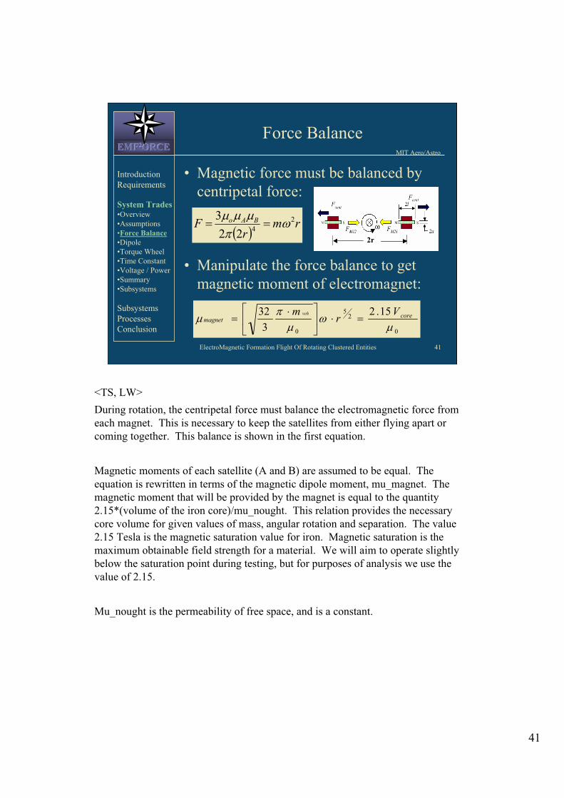
<TS, LW>
During rotation, the centripetal force must balance the electromagnetic force from
each magnet. This is necessary to keep the satellites from either flying apart or
coming together. This balance is shown in the first equation.
Magnetic moments of each satellite (A and B) are assumed to be equal. The
equation is rewritten in terms of the magnetic dipole moment, mu_magnet. The
magnetic moment that will be provided by the magnet is equal to the quantity
2.15*(volume of the iron core)/mu_nought. This relation provides the necessary
core volume for given values of mass, angular rotation and separation. The value
2.15 Tesla is the magnetic saturation value for iron. Magnetic saturation is the
maximum obtainable field strength for a material. We will aim to operate slightly
below the saturation point during testing, but for purposes of analysis we use the
value of 2.15.
Mu_nought is the permeability of free space, and is a constant.
41

ElectroMagnetic Formation Flight Of Rotating Clustered Entities 42
MIT Aero/Astro EMFEMFEMF222ORCEORCEORCE
Determination of Core Mass
• Using the relation for material density,
substitute the following values into the
magnetic moment equation:
coremV core
3-
1-
227
mkg7000
s15
2
m5.0
Askgm104
r
o
15.2
7000
3
322
521
rmm ovehiclecore
Introduction
Requirements
System Trades •Overview
•Assumptions
•Force Balance
•Dipole
•Torque Wheel
•Time Constant
•Voltage / Power
•Summary
•Subsystems
Subsystems
Processes
Conclusion
<TS, LW>
The magnetic moment equation was manipulated to provide an equation for the mass of the iron core. This equation gives a relation between the mass of the magnetic core and the total vehicle mass (including the core mass).
A value of 7000 kg/m^3 was used as the density of iron.
A radius of 0.5 m was used because a separation distance of 1 m was assumed.
The value for omega used in this analysis is 2pi/15 rad/sec. The actual value will be mandated in the Requirements Document.
42

43
ElectroMagnetic Formation Flight Of Rotating Clustered Entities 43
MIT Aero/AstroEMFEMFEMF222ORCEORCEORCE
Core Mass vs. Vehicle Mass
Configuration not
Possible
15.2
7000
3
322
521
rmm ovehiclecore
vehiclecore mm
Introduction
Requirements
System Trades•Overview
•Assumptions
•Force Balance
•Dipole
•Torque Wheel
•Time Constant
•Voltage / Power
•Summary
•Subsystems
Subsystems
Processes
Conclusion
<JB, TS, LW>
The x-axis represents the total mass of the vehicle, which includes the mass of the
magnetic core. The y-axis represents the mass of only the magnetic core. Due to
this definition of ‘total mass,’ it is not possible to have a core mass greater than the
vehicle’s total mass. The straight line on the graph is the line core_mass =
vehicle_mass. Therefore, all configurations shown in the darkened area are not
possible.
The curve shown on the graph represents the core mass as a function of vehicle
mass. The point where the curve crosses the straight line is the smallest possible
configuration, where the entire vehicle mass consists of only the core mass (leaving
no room for any other components). All other possible configurations are located
along the curve to the right of this point.
The separation distance between the curve and the straight line represents the
available mass for all other system components.

ElectroMagnetic Formation Flight Of Rotating Clustered Entities 44
MIT Aero/Astro EMFEMFEMF222ORCEORCEORCE
Core Mass vs. Vehicle Mass vs. Radius
Adding radius to the previous graph as a third dimension: Introduction
Requirements
System Trades •Overview
•Assumptions
•Force Balance
•Dipole
•Torque Wheel
•Time Constant
•Voltage / Power
•Summary
•Subsystems
Subsystems
Processes
Conclusion
<JB, TS, LW>
This graph shows the previous graph with the added dimension of radius of separation.
Vehicle configuration options are feasible until the radius of separation increases to a certain critical value. This point is shown on the graph where the curve (core_mass as a function of vehicle_mass and radius) breaches the flat plane (core_mass = vehicle_mass).
Feasible options are only those for which the curve lies beneath the flat plane.
44

ElectroMagnetic Formation Flight Of Rotating Clustered Entities 45
MIT Aero/Astro EMFEMFEMF222ORCEORCEORCE
Spin-up Representation
• Magnetic force diagrams before and
during spin-up
Introduction
Requirements
System Trades •Overview
•Assumptions
•Force Balance
•Dipole
•Torque Wheel
•Time Constant
•Voltage / Power
•Summary
•Subsystems
Subsystems
Processes
Conclusion
<JB,TS, LW>
The diagram on the left depicts two stationary dipoles just before spin-up. The
straight arrows represent net forces on each dipole. The curved arrows represent net
moments on each dipole.
The diagram on the right depicts the two dipoles as they begin to spin up. The
dipoles begin perpendicular to each other. As soon as a current is applied to the
electromagnets, forces and moments are induced in the dipoles. The moments are
due to the perpendicular geometry of the system at this point. These moments must
be counteracted by an applied torque from the torque wheels. The dipoles initially
move in the directions of their respective net forces. As they begin to move the
applied torque is decreased to induce centripetal motion. As centripetal force
increases, the applied torque continuously decreases, which allows the rotating
dipoles to slowly become aligned along the same axis. At the point when there is no
more applied torque, the dipoles are perfectly aligned and the centripetal force
equals the magnetic force. The system is now in steady-state.
45

ElectroMagnetic Formation Flight Of Rotating Clustered Entities 46
MIT Aero/Astro EMFEMFEMF222ORCEORCEORCE
Dipole Assumptions/Constraints
• Infinitely long solenoid
– is aspect ratio
• Operation in far field
– May need to relax to
preserve design freedom
•
– Magnet mass is large portion of system
mass
102 a
102 r
totalmagnet mm 5.
Introduction
Requirements
System Trades •Overview
•Assumptions
•Force Balance
•Dipole
•Torque Wheel
•Time Constant
•Voltage / Power
•Summary
•Subsystems
Subsystems
Processes
Conclusion
<LW>
These assumptions are constraints which the system would ideally satisfy. However, by fixing all these parameters, design freedom is removed from the system. The design would be fully constrained. Therefore, some of these assumptions must be relaxed through the course of the design process.
Alpha is the aspect ratio. To satisfy the assumption that the solenoid is infinitely long, alpha should be at least 10.
is the length of the solenoid.
a is the radius of the solenoid.
Beta is a parameter that measures the far-field capability of the system. To satisfy the assumption of operation in the far-field, beta should be ~10.
2r is the distance of separation, as defined in configuration assumptions.
It is also assumed that the magnet comprises a significant proportion of the total vehicle mass (one half of the total vehicle mass). This is a rough estimate based on the properties of electromagnets. The assumption is based specifically on the fact that electromagnets are heavy and weak.
46

ElectroMagnetic Formation Flight Of Rotating Clustered Entities 47
MIT Aero/Astro EMFEMFEMF222ORCEORCEORCE
Dipole Assumptions/Constraints
• Combining previous constraints:
• Applying to original force balance:
• System is over-constrained – is defined by the Requirements Document
– ‘a’ is automatically defined by system mass
– No choice for geometry of system
• Must relax one of the constraints
102
2
r
aar 100
2
211
1200
102.3
B
ma
Introduction
Requirements
System Trades •Overview
•Assumptions
•Force Balance
•Dipole
•Torque Wheel
•Time Constant
•Voltage / Power
•Summary
•Subsystems
Subsystems
Processes
Conclusion
<LW>
Here both the far-field approximation and the infinite solenoid approximation are
applied, as shown in the first equation. When these two constraints are applied
simultaneously, r=100a.
The analysis begins with the original force balance equation. The relation r=100a is
plugged into the force balance equation, as is the relation for magnetic moment,
mu=BV/mu_nought. Here B is the applied magnetic field strength and V is the
volume of the magnetic core. The relation for ‘a’ is found by simplifying the
resulting expression.
The expression for ‘a’ shows that the system is over-constrained. ‘a’ is only a
function of omega and m. Omega is defined for the system in the Requirements
Document. Therefore, ‘a’ is only a function of the mass of the system. As ‘a’ is
directly related to l and r through the constraints, this means that for every mass of
the system, there is a corresponding system geometry that is defined on the basis of
the dipole assumptions.
Since it is not ideal to have system geometry defined solely by total mass, it is
necessary to relax one of the constraints placed on the system. It is most likely that
the far-field assumption will be relaxed, because some of our testing facilities may
not capable of running tests in the far-field.
47

ElectroMagnetic Formation Flight Of Rotating Clustered Entities 48
MIT Aero/Astro EMFEMFEMF222ORCEORCEORCE
Torque Wheel
• Counter torque is required to initiate formation rotation
• Torque wheel must satisfy conservation of angular momentum:
• Known parameters: – reactionwheel (structural constraint)
– formation,rformation (from Requirements Document)
• Can solve for mass and radius of torque wheel
2
2
eelreactionwheelreactionwheelreactionwh
formationvehicleformation
rm
rmH
Introduction
Requirements
System Trades •Overview
•Assumptions
•Force Balance
•Dipole
•Torque Wheel
•Time Constant
•Voltage / Power
•Summary
•Subsystems
Subsystems
Processes
Conclusion
<JB, TS, LW>
It is assumed that the torque wheel is a ring. The moment of inertia, I, is represented as: I=mr2.
In order to satisfy the conservation of angular momentum, the angular momentum of the vehicles in steady-state rotation must be equal to the angular momentum of the torque wheels at the instant spin-up begins.
The parameters omega_reactionwheel, omega_formation, and r_formation are given properties of the system. Therefore, the conservation of angular momentum relationship provides a method to find the mass and radius of the reaction wheel as a function of total vehicle mass.
48

ElectroMagnetic Formation Flight Of Rotating Clustered Entities 49
MIT Aero/Astro EMFEMFEMF222ORCEORCEORCE
Electromagnet Time Constant
• Looking at equations that govern overall system dynamics:
– System time constant = rotation rate of the system, .
• To control the system, electromagnet time constant must be less than the system time constant.
• Electromagnet time constant is L/R.
– Need to find equations for inductance and resistance.
Introduction
Requirements
System Trades •Overview
•Assumptions
•Force Balance
•Dipole
•Torque Wheel
•Time Constant
•Voltage / Power
•Summary
•Subsystems
Subsystems
Processes
Conclusion
<TAS>
The time constant of the electromagnet is an important factor, since a small time
constant means a faster response from the electromagnet. Looking at the equations
of the dynamics of the system, the natural system time constant is equal to the
rotation rate of the entire formation. The time constant of the electromagnet should
thus be smaller than this value. The equation for the electromagnet time constant is
L/R (inductance/resistance), so we need to find equations for these now.
49

ElectroMagnetic Formation Flight Of Rotating Clustered Entities 50
MIT Aero/Astro EMFEMFEMF222ORCEORCEORCE
Electromagnet Time Constant
• The inductance of the electromagnet is:
where µcore is the magnetic permeability of the core
material and n is the number of turns per unit length(N/ ).
• The induced magnetic field of the magnet is:
• Substituting:
VnL core
2
inB coremag
i
nVBL
mag
Introduction
Requirements
System Trades •Overview
•Assumptions
•Force Balance
•Dipole
•Torque Wheel
•Time Constant
•Voltage / Power
•Summary
•Subsystems
Subsystems
Processes
Conclusion
<JB, TAS>
Here the equations for inductance and induced magnetic field are combined to
produce an equation for inductance in terms of induced magnetic field, number of
wire turns per length, volume of the core, and current.
50

ElectroMagnetic Formation Flight Of Rotating Clustered Entities 51
MIT Aero/Astro EMFEMFEMF222ORCEORCEORCE
Electromagnet Time Constant
• For a wire with length s, resistivity and radius rwire, resistance is
described by:
• Using the standard wire gauge relationship:
• Due to geometry, s = N*2 a:
• Recall:
2
wirer
sR
02c
r
i
wire
i
aNcR 02
0
2 )( aBmagmag
a2
31
0
2mag
mag
Ba
Introduction
Requirements
System Trades •Overview
•Assumptions
•Force Balance
•Dipole
•Torque Wheel
•Time Constant
•Voltage / Power
•Summary
•Subsystems
Subsystems
Processes
Conclusion
<TAS>
Here an initial equation for resistance is given. Next, the relationship for standard
wire gauges is noted. For most wires, the maximum current it can carry divided by
pi*wire_radius^2 is a constant. The value of this constant is the same for most all
wire gauges. The length of the wire is then put in terms of number of turns and core
diameter. This yields an expression for resistance in terms of material resistivity,
number of turns, radius of the core, and current.
It is possible to find an expression for the radius of the core. Recalling the two
given equations, the necessary radius of the core can be written as a function of
magnetic moment, induced magnetic field, and alpha (the aspect ratio of the core).
51

ElectroMagnetic Formation Flight Of Rotating Clustered Entities 52
MIT Aero/Astro EMFEMFEMF222ORCEORCEORCE
Electromagnet Time Constant
• Combining the above expressions
yields the equation for L/R:
• Want L/R as low as possible for
maximum control and stability.
31
32
31
0
0 22
1magnet
magnetB
cR
L
Introduction
Requirements
System Trades •Overview
•Assumptions
•Force Balance
•Dipole
•Torque Wheel
•Time Constant
•Voltage / Power
•Summary
•Subsystems
Subsystems
Processes
Conclusion
<TAS>
By combining the equations for inductance and resistance, the result is the equation
shown. The time constant L/R is a function of resistivity, magnetic moment, the
induced magnetic field in the core, and the aspect ratio.
It is now possible to plug in values and see how the time constant varies with
respect to different parameters.
52

ElectroMagnetic Formation Flight Of Rotating Clustered Entities 53
MIT Aero/Astro EMFEMFEMF222ORCEORCEORCE
Time Constant vs. Aspect Ratio
Assuming the following values:Introduction
Requirements
System Trades •Overview
•Assumptions
•Force Balance
•Dipole
•Torque Wheel
•Time Constant
•Voltage / Power
•Summary
•Subsystems
Subsystems
Processes
Conclusion
T15.2
AN104
mA645
mA1025.2
m10724.1
2-7
0
2
2-6
0
8
magnet
magnet
B
c
<TAS, JB, LW>
This is the graph of time constant vs. aspect ratio. The values assumed are:
Rho: the resistivity of copper wire
C_o: this value was computed using data from standard 20, 22, and 24 gauge wire.
Mu_magnet: this value was computed from the earlier equation mu_magnet = 2.15*Volume_core/mu_nought.
Mu_nought: this is the permeability of free space.
Bmagnet: this is the saturation point for iron.
This graph shows that by increasing the aspect ratio of the magnet, the time constant will also be increased.
We expect to be operating at an aspect ratio of ~10, meaning the time constant of the electromagnet should be around 2.3.
53

ElectroMagnetic Formation Flight Of Rotating Clustered Entities 54
MIT Aero/Astro EMFEMFEMF222ORCEORCEORCE
Time Constant vs. Resistivity
Assuming the following values:Introduction
Requirements
System Trades •Overview
•Assumptions
•Force Balance
•Dipole
•Torque Wheel
•Time Constant
•Voltage / Power
•Summary
•Subsystems
Subsystems
Processes
Conclusion
T15.2
AN104
mA645
mA1025.2
10
2-7
0
2
2-6
0
magnet
magnet
B
c
<JB, TS, LW>
This is the graph of time constant vs. resistivity. The values assumed are the same
as before, except here an aspect ratio of 10 is chosen, and the resistivity is allowed
to vary.
This graph shows that a reduction in the time constant may be achieved using wires
with higher resistivities. The resistivity of copper is shown since that is the most
readily available type of wire.
54

ElectroMagnetic Formation Flight Of Rotating Clustered Entities 55
MIT Aero/Astro EMFEMFEMF222ORCEORCEORCE
Applied Voltage
• Resistance:
• Ohm’s law:
• Recall value for core radius:
• Obtain final voltage equation:
31
32
0
02
4mag
mag
BncV
i
aNcR 02
iRV
31
0
2mag
mag
Ba
Introduction
Requirements
System Trades •Overview
•Assumptions
•Force Balance
•Dipole
•Torque Wheel
•Time Constant
•Voltage / Power
•Summary
•Subsystems
Subsystems
Processes
Conclusion
<JB, TS, LW>
This derivation for voltage is the voltage that must be applied to the system.
The resistance given is that previously derived from the wire gauge relationship and
B
wire geometry.
‘a’ is the radius of the core, which was previously derived.
m is the induced magnetic field, measured in Tesla.
55

ElectroMagnetic Formation Flight Of Rotating Clustered Entities 56
MIT Aero/Astro EMFEMFEMF222ORCEORCEORCE
Voltage vs. Aspect Ratio
Assuming the following values:Introduction
Requirements
System Trades •Overview
•Assumptions
•Force Balance
•Dipole
•Torque Wheel
•Time Constant
•Voltage / Power
•Summary
•Subsystems
Subsystems
Processes
Conclusion
8-
2-7
0
2
-26
0
101.724
m0.3
wire)gauge(22
turns465N
T15.2
AN104
mA645
mA1025.2
magnet
magnet
B
c
<LW>
This plot of voltage vs. aspect ratio shows that voltage increases exponentially with
aspect ratio. For an aspect ratio of 10 (according to infinitely long solenoid
approximation) a voltage of ~2.5 volts is required.
56

ElectroMagnetic Formation Flight Of Rotating Clustered Entities 57
MIT Aero/Astro EMFEMFEMF222ORCEORCEORCE
Voltage vs. Resistivity
Assuming the following values:
10
m0.3
wire)gauge(22
turns465N
T15.2
AN104
mA645
mA1025.2
2-7
0
2
-26
0
magnet
magnet
B
c
Introduction
Requirements
System Trades •Overview
•Assumptions
•Force Balance
•Dipole
•Torque Wheel
•Time Constant
•Voltage / Power
•Summary
•Subsystems
Subsystems
Processes
Conclusion
<JB, TS, LW>
For 22 gauge wire, N=465 due to geometry.
This plot shows a linear relationship between resistivity and required voltage for a given B field. So, while resistivity does not have a large effect on time constant (shown before), it has a more substantial effect on the required voltage, and should be taken into consideration in this case.
57

ElectroMagnetic Formation Flight Of Rotating Clustered Entities 58
MIT Aero/Astro EMFEMFEMF222ORCEORCEORCE
Power Required
• Current:
– is magnetic susceptibility
• Power:
• Using expanded voltage equation,
obtain final power equation:
N
Bi
mag
0
iVP
31
32
31
0
0
2
4 magmagBcP
applied
mag
B
BIntroduction
Requirements
System Trades •Overview
•Assumptions
•Force Balance
•Dipole
•Torque Wheel
•Time Constant
•Voltage / Power
•Summary
•Subsystems
Subsystems
Processes
Conclusion
<JB, TS, LW>
The current is derived from the definition of magnetic field, where B = (mu_nought)(chi)(ni). Chi is the magnetic susceptibility, which is a material property. Chi is equal to the ratio of the induced magnetic field to the applied magnetic field.
Using the relationship for power (P=iV) and the previously derived voltage expression, the final power equation is found. This equation dictates how much power the system requires.
58

ElectroMagnetic Formation Flight Of Rotating Clustered Entities 59
MIT Aero/Astro EMFEMFEMF222ORCEORCEORCE
Power vs. Aspect Ratio
Assuming the following values:Introduction
Requirements
System Trades •Overview
•Assumptions
•Force Balance
•Dipole
•Torque Wheel
•Time Constant
•Voltage / Power
•Summary
•Subsystems
Subsystems
Processes
Conclusion
8
2-7
0
2
-26
0
10724.1
5000
m0.3
wire)gauge(22
turns465N
T15.2
AN104
mA645
mA1025.2
magnet
magnet
B
c
<LW>
The graph shows power vs. aspect ratio. For an aspect ratio of 10 (which satisfies
the infinitely long solenoid assumption) this plot predicts a required power of ~0.55
Watts. Here we assumed a 22 gauge copper wire, with a resistivity given in the
table at the right.
59

ElectroMagnetic Formation Flight Of Rotating Clustered Entities 60
MIT Aero/Astro EMFEMFEMF222ORCEORCEORCE
Power vs. Resistivity
Assuming the following values:Introduction
Requirements
System Trades •Overview
•Assumptions
•Force Balance
•Dipole
•Torque Wheel
•Time Constant
•Voltage / Power
•Summary
•Subsystems
Subsystems
Processes
Conclusion
10
5000
m0.3
wire)gauge(22
turns465N
T15.2
AN104
mA645
mA1025.2
2-7
0
2
-26
0
magnet
magnet
B
c
<LW>
There is a linear relationship between power and resistivity. The red lines show the
power estimate when a 22 gauge copper wire is used. The resistivity of copper wire
is shown in the parameters at the right as rho. This graph shows a similar power
estimate as is predicted by the power vs. aspect ratio graph, approximately 0.55
Watts.
60

ElectroMagnetic Formation Flight Of Rotating Clustered Entities 61
MIT Aero/Astro EMFEMFEMF222ORCEORCEORCE
Power Relationships
• Power is directly related to the time
constant, L/R
– Both are proportional to
– Increase power to decrease L/R
31
32
31
0
0
2
4 magmagBcP
31
32
31
0
0 22
1magnet
magnetB
cR
L
Introduction
Requirements
System Trades •Overview
•Assumptions
•Force Balance
•Dipole
•Torque Wheel
•Time Constant
•Voltage / Power
•Summary
•Subsystems
Subsystems
Processes
Conclusion
<LW>
The expressions for L/R and P are given again here. It is clear that power is directly
related to the time constant. This is an interesting relationship to consider when
designing a control system, as the goal is to minimize the time constant. Power may
be a limiting factor in control system design.
61

ElectroMagnetic Formation Flight Of Rotating Clustered Entities 62
MIT Aero/Astro EMFEMFEMF222ORCEORCEORCE
System Trades Summary
• Found core mass as a function of vehicle mass (force balance equations). – Certain values of core mass were invalid.
– A maximum allowable radius of separation exists.
• Both far field and infinitely long solenoid assumptions over-constrained the system. – Relax one constraint (most likely far field).
• Found required moment of inertia of the torque wheels (conservation of angular momentum).
Introduction
Requirements
System Trades •Overview
•Assumptions
•Force Balance
•Dipole
•Torque Wheel
•Time Constant
•Voltage / Power
•Summary
•Subsystems
Subsystems
Processes
Conclusion
<TAS>
After analyzing the governing equations for the system, several major design tradeoffs were noted.
An equation for core mass was found in terms of total mass of the system and radius of separation. Here, we saw that some total mass values below a certain point were invalid because the iron core would have been heavier than the total mass (which includes the iron core). If you increased the total mass of the system beyond this critical point, the percentage of total mass taken up by core mass decreased, leaving larger amounts of mass available for all other components. These relations were then plotted on a 3-D graph, where radius was allowed to vary. This showed that for values of radius above a certain point, the values for core and total mass were invalid.
An analysis was made on the far-field and infinitely long solenoid assumptions. This analysis showed that when these assumptions are both put into place, the system is over-constrained, leaving no freedom for the selection of core radius. Freedom is restored if one of these assumptions is relaxed, which will likely be the far-field assumption.
By looking at the conservation of momentum equations, the required moment of inertia for the torque wheel could be found. Depending on the geometry of the torque wheel, estimates of radius and mass could then be made.
62

ElectroMagnetic Formation Flight Of Rotating Clustered Entities 63
MIT Aero/Astro EMFEMFEMF222ORCEORCEORCE
System Trades Summary
• Found electromagnetic time constant
(inductance and resistance equations).
– Time constant most easily changed by varying
the aspect ratio of the electromagnet.
• Found equations for voltage and power.
– Also a function of aspect ratio.
• Showed that decreasing the time constant
increases the necessary power.
• What now?
– Apply these trades to the various subsystems.
Introduction
Requirements
System Trades •Overview
•Assumptions
•Force Balance
•Dipole
•Torque Wheel
•Time Constant
•Voltage / Power
•Summary
•Subsystems
Subsystems
Processes
Conclusion
<TAS>
By finding equations for inductance and resistance, the time constant of the electromagnet was found (L/R). This equation showed that the time constant depended mostly on aspect ratio of the magnet, and somewhat on the resistivity of the wire used in the coils. However, since it is difficult to obtain wires with abnormally high resistivities, it is easiest to vary the aspect ratio in order to vary the time constant. The objective of varying the time constant is to make it as small as possible in order to provide as much control as possible over the system.
Equations for voltage and power were then derived. These equations also depended primarily on aspect ratio and resistivity. Through comparison with the time constant equation, it was shown that any effort to reduce the time constant would result in higher power requirements.
The next step in the design process is to apply these overall system trades to the individual subsystem designs.
63
ElectroMagnetic Formation Flight Of Rotating Clustered Entities 64
MIT Aero/Astro EMFEMFEMF222ORCEORCEORCE
Introduction to Subsystems
EMF2ORCE will be composed of the
following subsystems:
• Avionics: provides necessary computational
power
• Communication: transmits data between
vehicles and ground base
• Metrology: measures attitude and position
of vehicles through onboard sensoring
system
Introduction
Requirements
System Trades •Overview
•Assumptions
•Force Balance
•Dipole
•Torque Wheel
•Time Constant
•Voltage / Power
•Summary
•Design Concept
Subsystems
Processes
Conclusion
<TAS>
The overall system will be divided into six major subsystems:
Avionics: these are the onboard computers that will run the program codes and control the system as a whole. They will also act as an interface between the communication, metrology, attitude control, and power systems.
Communication: this subsystem will be responsible for transmitting data from vehicle to vehicle and from each vehicle to the ground base. Some of the different types of data to be transmitted include telemetry, system health, and attitude and position measurements.
Metrology: this is the method by which attitude and position of each vehicle will be determined. Onboard sensors will be used to make these measurements, which will then be passed to the control system.
64

ElectroMagnetic Formation Flight Of Rotating Clustered Entities 65
MIT Aero/Astro EMFEMFEMF222ORCEORCEORCE
Introduction to Subsystems
Introduction
Requirements
System Trades •Overview
•Assumptions
•Force Balance
•Dipole
•Torque Wheel
•Time Constant
•Voltage / Power
•Summary
•Design Concept
Subsystems
Processes
Conclusion
• Attitude Control: combines previous three subsystems with electromagnets and torque wheels to control attitude and relative positions.
• Power: provides the necessary voltage and current needed to operate the system
• Structure:– Basic structure: holds all components together
– Magnetic shielding: shields avionics from potential damage due to the magnetic field
– Air carriage: provides a frictionless way to operate vehicles on the testbed
<TAS>
Subsystems (cont):
Attitude Control: the attitude and relative position of each vehicle will be controlled
by the electromagnets. By varying the current through each electromagnet, the
vehicles can be controlled to perform complex configurations, including spin-up
and spin-down maneuvers. This subsystem will also include the torque wheels
which will provide the necessary angular momentum reactions.
Power: this will provide the necessary currents and voltages to the other subsystems.
Structure: there are three components to the main structure – the basic structure, the
magnetic shielding, and the air carriages. The basic structure will be responsible for
holding all the system components together and forming the outer shell of the
vehicles. Magnetic shielding will most likely be necessary to protect the avionics
and sensors from possible damage due to the presence of a strong magnetic field
from the electromagnet. Finally, air carriages will be needed to produce a
frictionless environment in which to perform operation tests on the vehicles.
65

ElectroMagnetic Formation Flight Of Rotating Clustered Entities 66
MIT Aero/Astro EMFEMFEMF222ORCEORCEORCE
Design Concept
Introduction
Requirements
System Trades •Overview
•Assumptions
•Force Balance
•Dipole
•Torque Wheel
•Time Constant
•Voltage / Power
•Summary
•Design Concept
Subsystems
Processes
Conclusion
Sensor Data Stream
Ground/Sat 1
Communication
Antennae
Ground
Control
Air
Cushion
Air
Carriage
Structure
Power
System
Reaction
Wheel
Electromagnet
(Attitude Control)
Avionics,
Communication,
Metrology
Sensors
<TAS, JEU, ESS>
Here is an artistic rendition of what the final vehicles may look like. This
representation does not reflect any detailed analysis of the potential layout of the
various subsystems, but rather a basic preliminary design incorporating these
subsystems into a coherent structure. The subsystems are all contained within the
outer structure. The air carriages are fixed to the outside of the vehicle. The arrows
show the different lines of communication between the ground base and each
vehicle.
66

MIT Aero/Astro EMFEMFEMF222ORCEORCEORCE
Introduction
Requirements
System Trades
Subsystems •Overview
•Flowdown
•Avionics
•Communication
•Metrology
•Attitude Control
•Power
•Structure
Processes
Conclusion
Amilio Aviles
Stephanie Slowik
Subsystems Trade Analysis Review
<SJS>
This begins the Subsystem Trade Analysis and Review which will be prevented by Amilio Aviles, and Stephanie Slowik.
67

ElectroMagnetic Formation Flight Of Rotating Clustered Entities 68
MIT Aero/Astro EMFEMFEMF222ORCEORCEORCE
Subsystem Trades Overview
• Component classification and
subsystem breakdown
• Trade analysis for each component
Introduction
Requirements
System Trades
Subsystems •Overview
•Flowdown
•Avionics
•Communication
•Metrology
•Attitude Control
•Power
•Structure
Processes
Conclusion
<SJS>
The subsystems of the testbed have been determined. Metrics have been established
for each subsystem so that components with the most desirable parameters have
been researched. A thorough trade analysis has been done on each component. The
Databasing team has been in direct contact with various vendors and manufacturers
of components to discuss pricing, procurement time, and component specification
information. At the current time, it appears as if the majority of our components
can be bought COTS (Commercial Off The Shelf), with the exception of the casing,
the airbearings, and the Electro-Magnets.
68

ElectroMagnetic Formation Flight Of Rotating Clustered Entities 69
MIT Aero/Astro EMFEMFEMF222ORCEORCEORCE
Subsystem Flowdown
Power Amp
On-board Computer
Software
Signal Conditioning
Avionics
Ground Comm
Omnidirectional
Inter-device Comm
Communication
Inertial Metrology
Separation distance
Relative Metrology
Metrology
Actuation
Reaction
De-spin
ACS
Simulated Solar Cells
Power
Carriage
EM Shielding
Frictionless mount
Structure
Mission objective
Introduction
Requirements
System Trades
Subsystems •Overview
•Flowdown
•Avionics
•Communication
•Metrology
•Attitude Control
•Power
•Structure
Processes
Conclusion
<ALS, SWS, AA, MW, WDF >
The following diagram shows the flowdown of the subsystems and the various
components of each has determined from the mission objective. The six subsystems
include Avionics, Communication, Metrology, Attitude Control System, Power, and
Structure. We have collected information on various possible components for each
subsystem and will provide a preliminary recommendation for each component. A
more detailed flowdown will be developed when the final design has been
determined.
69
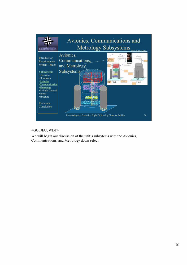
ElectroMagnetic Formation Flight Of Rotating Clustered Entities 70
MIT Aero/Astro EMFEMFEMF222ORCEORCEORCE
Avionics, Communications and
Metrology Subsystems
Avionics,
Communications,
and Metrology
Subsystems
Introduction
Requirements
System Trades
Subsystems •Overview
•Flowdown
•Avionics
•Communication
•Metrology
•Attitude Control
•Power
•Structure
Processes
Conclusion
<GG, JEU, WDF>
We will begin our discussion of the unit’s subsytems with the Avionics, Communications, and Metrology down select.
70
ElectroMagnetic Formation Flight Of Rotating Clustered Entities 71
MIT Aero/Astro EMFEMFEMF222ORCEORCEORCE
Avionics Candidates
• HandyCricket
• Tattletale/TIM-DIO (SPHERES)
• TI-C40
• TI-C6701
• Tiny Processors (DARPA)
Introduction
Requirements
System Trades
Subsystems •Overview
•Flowdown
•Avionics
•Communication
•Metrology
•Attitude Control
•Power
•Structure
Processes
Conclusion
<DA,AA>
The candidates for the avionics system are listed above.
71

ElectroMagnetic Formation Flight Of Rotating Clustered Entities 72
MIT Aero/Astro EMFEMFEMF222ORCEORCEORCE
Avionics Selection Metrics
• Processor Speed
• Mass
• Memory
• Power Consumption
• Cost
Introduction
Requirements
System Trades
Subsystems •Overview
•Flowdown
•Avionics
•Communication
•Metrology
•Attitude Control
•Power
•Structure
Processes
Conclusion
<AA, DC, GG>
The processor speed is important because it must operate quickly and efficiently
enough for our satellites to do the following tasks when needed: take inputs from
sensors, understand commands, coordinate communication with other satellites and
ground station, control actuators, etc. Mass, cost, and power are all criteria which
need to be minimized in order to keep the power consumption, mass, and cost of the
entire vehicle low.
72

ElectroMagnetic Formation Flight Of Rotating Clustered Entities 73
MIT Aero/Astro EMFEMFEMF222ORCEORCEORCE
Candidate Specifications
119128<.03167TI-C6701
Unfortunately, this information is not currently
available to us, however we will further investigate this
possibility when the information is available.
Tiny
Processors
(DARPA)
313None<.0360TI-C40
1190256.02816TattleTale
4932N/AN/AHandy
Cricket
Cost
(US $)
Memory
(KB)
Mass
(Kg)
Speed
(MHz)
Processor Introduction
Requirements
System Trades
Subsystems •Overview
•Flowdown
•Avionics
•Communication
•Metrology
•Attitude Control
•Power
•Structure
Processes
Conclusion
<DC, AA, GG>
This table compares the five selection metrics of the candidate systems. Some
information was not available. Note that some systems are complete and ready to
program, while others are simply microprocessors and require auxiliary hardware in
order to function within the range of required applications.
73

ElectroMagnetic Formation Flight Of Rotating Clustered Entities 74
MIT Aero/Astro EMFEMFEMF222ORCEORCEORCE
Final Downselect
-Still under
development
-Small Memory
Capacity
-No Memory-
requires auxiliary
-Comparatively
Expensive
-IR may be
extraneous
-Limited clock speed
Cons
No
YES
No
No
No
Downselect
Decision
-Incorporates RF
componets
-Very Fast Clock
Speed
-Fast Clock Speed
-Used on SPHERES
-Adequate Clock
Speed
-Incorporates IR
Communication
-Programmable
Pros
TI-C6701
Processors
(DARPA)
TI-C40
TattleTale
Handy
Cricket
ProcessorIntroduction
Requirements
System Trades
Subsystems •Overview
•Flowdown
•Avionics
•Communication
•Metrology
•Attitude Control
•Power
•Structure
Processes
Conclusion
<DC, AA>
This table shows the final downselection process. The pros and cons of each system
are indicated, resulting in a final selection. This selection process was used because
most candidates were easily ruled out based on infeasibility issues. Note that the
final selection does require auxiliary hardware. Although this is the final selection
currently made, it is not set in stone and is also dependent on the development of
other sub-systems.
74

ElectroMagnetic Formation Flight Of Rotating Clustered Entities 75
MIT Aero/Astro EMFEMFEMF222ORCEORCEORCE
Communications
Possible Design Options
• Radio Frequency
• Infrared
• Umbilical
• Ultrasonic
• Laser
Introduction
Requirements
System Trades
Subsystems •Overview
•Flowdown
•Avionics
•Communication
•Metrology
•Attitude Control
•Power
•Structure
Processes
Conclusion
<GG, AA>
RF communication using some frequency of radio waves
Infrared uses modulation of IR beam to transmit information (like a TV remote control)
Umbilical external cable attaches physically to the vehicles
Ultrasonic uses sound waves to transmit information
Laser uses modulation of a laser beam to transmit information.
75

ElectroMagnetic Formation Flight Of Rotating Clustered Entities 76
MIT Aero/Astro EMFEMFEMF222ORCEORCEORCE
Design Metrics
• Feasibility – can this system be applied to the
formation flying satellites
• Bandwidth – how much information must be
transmitted
• Mass/size – can the system fit in our
satellites w/out adding a lot of mass
• Power
• Cost
• Range
Introduction
Requirements
System Trades
Subsystems •Overview
•Flowdown
•Avionics
•Communication
•Metrology
•Attitude Control
•Power
•Structure
Processes
Conclusion
<GG>
From these criteria we can rule out infrared or laser because they both require accurate aiming amongst satellites. In our final system, it will be difficult to have specific points on satellites face each other. This makes these systems less feasible and therefore undesirable.
We have therefore down-selected the communications architecture to radio- frequency.
<GG>
Because we are currently unsure of how much data we need to transmit we wish to maximize our bandwidth.
Power consumption must remain low to keep the power supply simple and adequate for an extended period of time.
Mass and volume must be minimized in order to keep the mass and size of the entire vehicle small.
76

ElectroMagnetic Formation Flight Of Rotating Clustered Entities 77
MIT Aero/Astro EMFEMFEMF222ORCEORCEORCE
Rejected Design Options
• Infrared & laser – highly directional,
limits mobility of vehicles
• Umbilical – does not meet
requirements, interferes with dynamics
• Ultrasonic – expensive, harder to
implement
Introduction
Requirements
System Trades
Subsystems •Overview
•Flowdown
•Avionics
•Communication
•Metrology
•Attitude Control
•Power
•Structure
Processes
Conclusion
<GG, AA>
Infrared and laser communications require a direct line of sight between the emitter
and the sensor. Rotation of the vehicles might disrupt the data stream.
Umbilical will require physical connection to vehicles which might interfere with
their free motion. Umbilical might become entangled for a rotating formation of
vehicles.
Ultrasonic are semi-directional. Signals could easily interfere with signals from
ground station or other vehicles.
77

ElectroMagnetic Formation Flight Of Rotating Clustered Entities 78
MIT Aero/Astro EMFEMFEMF222ORCEORCEORCE
Communications Requirements
• Bandwidth is estimated by
– The amount of data and how often we want to
transmit the data, known as the bit-rate
(Amount of floating point numbers wish to transmit)
X (64 bits per floating point number)
X (number of times per second we want to transmit
these number)
= (Bit rate)
• Noise and the encoding create additional
system needs
– Therefore multiply this bit rate estimate by two
Introduction
Requirements
System Trades
Subsystems •Overview
•Flowdown
•Avionics
•Communication
•Metrology
•Attitude Control
•Power
•Structure
Processes
Conclusion
<GG>
This is how bandwidth is calculated, but because we will most probably need to
transmit several floating point numbers several times a second we know we will
want a high bandwidth. We do not do the calculations of the bandwidth needed
instead we will look to choose an architecture that maximizes this criterion.
78

ElectroMagnetic Formation Flight Of Rotating Clustered Entities 79
MIT Aero/Astro EMFEMFEMF222ORCEORCEORCE
Other Factors
• Communications system must be
able to connect to main processing
board and should also be able to
connect to the metrology system.
• System must also be able to
communicate with the ground
station. (laptop)
Introduction
Requirements
System Trades
Subsystems •Overview
•Flowdown
•Avionics
•Communication
•Metrology
•Attitude Control
•Power
•Structure
Processes
Conclusion
<GG>
These are other criteria that should be considered when finally down selecting a particular RF system.
79

ElectroMagnetic Formation Flight Of Rotating Clustered Entities 80
MIT Aero/Astro EMFEMFEMF222ORCEORCEORCE
Communication System Candidates
Introduction
Requirements
System Trades
Subsystems •Overview
•Flowdown
•Avionics
•Communication
•Metrology
•Attitude Control
•Power
•Structure
Processes
Conclusion 1000180RF 2968
N/A330RF 2938
19.236DR 3100
11536TR 3003
11536TR 100
Data Rate
(Kbps)
Power
(mW)
SYSTEM
<AA,GG>
These chips are estimated as within one cubic centimeter and 6 grams of each other, we consider these estimates negligible and therefore do not include them in the table.
The first three are from RF Monolithics (www.rfm.com)
The last two are from RF Microdevices (www.rfmd.com)
Mass and volume for all chips are very similar, so no valuable comparison could be made using those parameters.
Final conclusion will be tentative pending price information which we have requested. Obviously the RF2969 Chip provides the best bandwidth, however it also requires more power. Our final decision will be tentative on how the final design fits together, if it can supply enough power, and how much bandwidth is enough.
We will also need to check for compatibility with the avionics and metrology systems.
80

ElectroMagnetic Formation Flight Of Rotating Clustered Entities 81
MIT Aero/Astro EMFEMFEMF222ORCEORCEORCE
Metrology Design Options
• Optical devices
– Infrared
– Laser
• Ultrasonic devices
Introduction
Requirements
System Trades
Subsystems •Overview
•Flowdown
•Avionics
•Communication
•Metrology
•Attitude Control
•Power
•Structure
Processes
Conclusion
<LW>
Optical devices: IR ranging devices measure distance by sensing reflection of IR waves. Laser ranging devices measure distance by one of two methods. The first is measuring the time-of-flight of the laser to reach the target and return. This method is used mainly for larger distances (> 1 m). The second method is the triangulation method, which is used for smaller distances (< 1 m).
<http://www.acroname.com/robotics/parts/R19-IR02.html>
<http://www.acuityresearch.com/prodov1.html#AR4000>
<http://www.ipm.fhg.de/english/fields/pp_monitoring/production/optical- ranging.html>
Ultrasonic devices: Work by sensing the reflection of high frequency sound waves. The devices function by one of two methods. The first is a triangulation method, which requires at least three transmitters and one receiver (time-of-flight method). The second method measures the phase difference in the signal between the transmitter and receiver (phase-coherence method).
<http://www.cs.nps.navy.mil/people/faculty/capps/4473/projects/chang2/Simple.ht m>
81

ElectroMagnetic Formation Flight Of Rotating Clustered Entities 82
MIT Aero/Astro EMFEMFEMF222ORCEORCEORCE
Rejected Design Options
• GPS-like system – very expensive to create an indoor GPS system
• Laser ranging – very expensive, only provides position between ground station and satellite system (global metrology system)
• Radio interferometry – unavailable on small scale needed for testing
• Electronic whiteboard technology – cannot track multiple targets
Introduction
Requirements
System Trades
Subsystems •Overview
•Flowdown
•Avionics
•Communication
•Metrology
•Attitude Control
•Power
•Structure
Processes
Conclusion
<AA, LW>
GPS-like system: There is no commercially available indoor GPS-like system. The system would require transmitters mounted inside the testing facility and a receiver on each of the satellites. The technology is still experimental, thus we would need to design our own system, which would be both time consuming and expensive. Therefore, this option is not feasible.
Laser Ranging: Laser ranging is a technology that provides position measurement between a ground station and a body in space. It is not practical for our purposes for two reasons. First, we are testing in an indoor facility. A large laser is not needed to provide global metrology (position measurement between the system and a ground station). Second, it is very expensive. Use of laser ranging would exceed the scope of the project’s budget.
<http://almagest.as.utexas.edu/~rlr/mlrs.html>
Radio Interferometry: Radio interferometry determines position by a triangulation method. It requires three antennae to determine the position of a body with a radio emissor. It is not feasible for use on this project, because the radio interferometry systems are not available on a small scale suited to our test environment.
<http://www.drao.nrc.ca/science/vlbi/principles/principles.shtml>
Electronic Whiteboard: Intended for use on board of ~1x2 m. The system uses a combination of IR and Sonic sensors to determine the location of the pen on the board. The system has high accuracy and works in realtime, but it cannot track multiple targets. Several systems cannot be used in overlapping regions.
<www.ebeam.com> 82

ElectroMagnetic Formation Flight Of Rotating Clustered Entities 83
MIT Aero/Astro EMFEMFEMF222ORCEORCEORCE
Design Metrics
• Range (maximize)
• Precision (minimize)
– Linear – must be precise to .015 m
– Angular – must be precise to +/- 1 arcsec
• Power needed (minimize)
• Cost (minimize)
• Mass (minimize)
Introduction
Requirements
System Trades
Subsystems •Overview
•Flowdown
•Avionics
•Communication
•Metrology
•Attitude Control
•Power
•Structure
Processes
Conclusion
<LW>
Range is the maximum distance away from the sensor at which another object can be sensed.
Precision is measured both in distance (linear) and angular position (angular). Requirements are those specified in the Requirements Document.
Precision is specified as the allowed tolerance for each measurement. Therefore, minimizing the ‘Precision’ variable will yield a very precise system.
Power needed is the power that must be supplied in order for the sensors to function.
83

ElectroMagnetic Formation Flight Of Rotating Clustered Entities 84
MIT Aero/Astro EMFEMFEMF222ORCEORCEORCE
Metrology System Candidates
N/A~2 W~.25 WPower
~28 deg~0 deg~0 degAngle
$119N/A$21Price
Mass
Precision
Range
~.03 kg.624 kg.003 kg
.01 m.00254 mN/A
.15-2.7m0-17m.1-.8m
SonicLaserIRIntroduction
Requirements
System Trades
Subsystems •Overview
•Flowdown
•Avionics
•Communication
•Metrology
•Attitude Control
•Power
•Structure
Processes
Conclusion
<AA, LW>
Infrared: Sharp GP2D02 Infrared Ranger.
Precision information not available.
<http://www.acroname.com/robotics/parts/R19-IR02.html>
Laser: Acuity Research AR4000 Laser Ranger.
Only available laser ranger for the scale we are working on – it is highly accurate, and meant for scientific measurement and machine control.
No pricing information given, assumed to be very expensive (hundred-thousands $).
<http://www.acuityresearch.com/prodov1.html#AR4000>
Ultrasonic: Ultrasonic Owl Scanner – Sonar Sensing Kit.
Sensor is mounted on a servo, and can therefore effectively cover an arc of 90 degrees.
Power draw information not available.
*Price includes computer interface and software, actual price should be cheaper.
<http://www.robotstore.com/catalog/display.asp?pid=217>
Prices are measured on a per unit basis.
Power needed is the maximum power possibly drawn by the sensing system.
Angle measures the angular range of the device.
84

ElectroMagnetic Formation Flight Of Rotating Clustered Entities 85
MIT Aero/Astro EMFEMFEMF222ORCEORCEORCE
Final Design Choice
• Ultrasonic sensing device – Meets all criteria from Requirements
Document• Maximum range of 2 m between bodies
• Minimum precision of .015 m
– Negligible mass compared to system mass
– Affordable (although more expensive than IR sensors)
Introduction
Requirements
System Trades
Subsystems •Overview
•Flowdown
•Avionics
•Communication
•Metrology
•Attitude Control
•Power
•Structure
Processes
Conclusion
<LW>
The current final design choice is the ultrasonic sensing device due to the fact that it satisfies all requirements.
The infrared sensors do not satisfy the maximum required range of 2 m. However, they are much more affordable than either the laser or the ultrasonic devices. They also have a much smaller mass that either of the other range finders. Additionally, they have a very small power draw. It is possible that a higher quality IR sensor is available, and may provide a better metrology solution.
The laser range finders are the most precise solution. However, they are not feasible due to the fact that they have a large mass and are exceedingly expensive.
85

ElectroMagnetic Formation Flight Of Rotating Clustered Entities 86
MIT Aero/Astro EMFEMFEMF222ORCEORCEORCE
Attitude Control Subsystem
ACSIntroduction
Requirements
System Trades
Subsystems •Overview
•Flowdown
•Avionics
•Communication
•Metrology
•Attitude Control
•Power
•Structure
Processes
Conclusion
< GG, JEU, WDF>
We will now move on to the downselect of the attitude control system.
86

ElectroMagnetic Formation Flight Of Rotating Clustered Entities 87
MIT Aero/Astro EMFEMFEMF222ORCEORCEORCE
ACS: Torque Wheels vs. CMG
• Experimental
•No vendors found
• FUSE failure
•Small, light,
accurate, versatile
• Commercially
available
• Several vendors
interested
• Variety of
specifications avail.
• Heavy, slightly
unwieldy
CMGTorque WheelIntroduction
Requirements
System Trades
Subsystems •Overview
•Flowdown
•Avionics
•Communication
•Metrology
•Attitude Control
•Power
•Structure
Processes
Conclusion
<ALS>
Our two options for mechanical attitude control are torque wheels and control
moment gyros, or CMG’s.
Upon first investigation, CMG’s appeared a better option because they are small,
light, accurate and versatile – more so than the traditional torque wheel.
Further study however, revealed that CMG’s are still an experimental technology.
They are not commercially available. In fact, the only real usage to date of a CMG
system was on NASA’s FUSE sattelite – recently publicized because of the failure
of its attitude control system.
Torque wheels will be more readily available and provide more options.
87

ElectroMagnetic Formation Flight Of Rotating Clustered Entities 88
MIT Aero/Astro EMFEMFEMF222ORCEORCEORCE
ACS: Torque Wheels
• Provide resistance to EM
torques enabling better
control
• Most use magnetic
bearingsSpecifications (30 kg vehicle)
• Moment: 0.1-2.0 N-m-s
• Weight: 0.7-4.5 lbs.
• Peak power: 1-27 W
• Size: 4x6 in. – 4x6 ¾ in.
•Nominal speed: 3000-8000
RPM
Introduction
Requirements
System Trades
Subsystems •Overview
•Flowdown
•Avionics
•Communication
•Metrology
•Attitude Control
•Power
•Structure
Processes
Conclusion
<ALS>
Torque wheels are required for our system to help control the actuation forces
provided by the electromagnets.
It is interesting to note that most commercially available torque wheels use
magnetic bearings. The far field effects of these magnets is not currently known
and interference with the B-field of the electromagnetic actuators will be
investigated.
Shown are ranges of some typical specifications for torque wheels appropriate for a
30kg unit. 30 kilograms was a very preliminary rough estimate drawn from the
preliminary architecture brainstorms. As the mass changes and is finalized, so too
will these specifications.
88

ElectroMagnetic Formation Flight Of Rotating Clustered Entities 89
MIT Aero/Astro EMFEMFEMF222ORCEORCEORCE
Electromagnets
ElectromagnetsIntroduction
Requirements
System Trades
Subsystems •Overview
•Flowdown
•Avionics
•Communication
•Metrology
•Attitude Control
•Power
•Structure
Processes
Conclusion
< GG, JEU, WDF>
The most important component in the system which demonstrates the feasibility of
electromagnetic control of formation flight is the electromagnet. This begins the
discussion of possible materials to be used to construct the system’s electromagnet.
89

ElectroMagnetic Formation Flight Of Rotating Clustered Entities 90
MIT Aero/Astro EMFEMFEMF222ORCEORCEORCE
EM Core MIT Aero/Astro
• Core material selection criteria • Permeability
• Bsaturation
• Cost and availability
• Material candidates • Ferromagnetic materials with high
permeabilities
• Material downselect • High-permeability materials with low
Bsaturation values
• Rare, exotic materials difficult and costly to
obtain and/or machine
Introduction
Requirements
System Trades
Subsystems •Overview
•Flowdown
•Avionics
•Communication
•Metrology
•Attitude Control
•Power
•Structure
Processes
Conclusion
<MSW>
EM Core Material Trade Analysis:
The core material selection criteria included permeability, Bsaturation, cost, and
availability. Permeability is a measure of the material’s magnifying effect on the
magnetic field. Bsaturation is extremely important for our application because it is a
measure of what field strength we can obtain when the core is saturated. Cost (and
subsequently, availability) is important because of budgetary constraints to our
program.
A wide variety of ferromagnetic materials were considered for the EM core ranging
from materials commonly used in industrial applications to rare, specialty materials.
There were two main reasons for materials to not be selected. First of all, many of
the materials with very high permeabilities had low values for Bsaturation, well below
those that would probably be required for our testbed. Secondly, many of the high-
permeability materials were quite rare. This made them extremely costly and also
difficult to machine since there were no vendors with the correct equipment and
expertise.
90

ElectroMagnetic Formation Flight Of Rotating Clustered Entities 91
MIT Aero/Astro EMFEMFEMF222ORCEORCEORCE
ACS: EM Core Material
8.74
6.9-7.3
7.87
Density
[g/cm3]
High7,500Extremely HighPermalloy 80
(80% Ni, 15%
Fe)
High10,000HighAlNiCo
Low21,000ModerateLow Carbon
Steel (99% Fe)
CostBsaturation
[gauss]
PermeabilityMaterial
http://www.grouparnold.com/mtc/
http://www.oz.net/~coilgun/theory/materials.htm
http://www.matweb.com
• Low Carbon Steel (AISI 1010)
• High Bsaturation
• Low Cost
• Wide Availability
Introduction
Requirements
System Trades
Subsystems •Overview
•Flowdown
•Avionics
•Communication
•Metrology
•Attitude Control
•Power
•Structure
Processes
Conclusion`
<MSW>
EM Core Material Trade Analysis:
A wide variety of soft ferrous materials were considered for use as the
electromagnet core. This table represents some of the more likely candidates based
on permeability, Bsatuaration, density, and cost.
Low carbon steel was chosen for its high value for Bsaturation and wide availability.
After speaking to several of the electromagnet and ferrite material vendors, it was
clear that low carbon steel (specifically, AISI 1010 or AISI 1020) would be the most
likely choice. Although other materials have extremely high permeabilities, their
values for Bsaturation were too low for our application. Additionally, these exotic
materials (such as permalloy and supermalloy) are extremely expensive and not
widely available. Low carbon steel is what is commonly used in industrial
applications and presents less of a machining challenge for manufacturers.
91

ElectroMagnetic Formation Flight Of Rotating Clustered Entities 92
MIT Aero/Astro EMFEMFEMF222ORCEORCEORCE
Power Subsystem
Power
System
Introduction
Requirements
System Trades
Subsystems •Overview
•Flowdown
•Avionics
•Communication
•Metrology
•Attitude Control
•Power
•Structure
Processes
Conclusion
< GG, JEU, WDF>
A major limitation to the successful design of the system is the ability to provide the necessary power to the electromagnets while still maintaining a low system mass.
92

ElectroMagnetic Formation Flight Of Rotating Clustered Entities 93
MIT Aero/Astro EMFEMFEMF222ORCEORCEORCE
Power
Introduction
Requirements
System Trades
Subsystems •Overview
•Flowdown
•Avionics
•Communication
•Metrology
•Attitude Control
•Power
•Structure
Processes
Conclusion
• Available options:
– Batteries
– Solar cells
– Beamed energy
• Metrics:
– High energy density (J/kg)
– Feasibility
• Using beamed energy not feasible for our
purposes
< SJS, WDF>
The available options for providing the necessary power to our vehicles include
Batteries, Solar Cells, or some form of beamed energy. The metrics used to
downselect these potential options include energy density and feasibility. It is
important to have a high energy density to help reduce the mass of the overall
system while still providing the necessary power. It is also important to make sure
any system we choose is within the scope of this design project. Beamed energy is
not feasible for this project and therefore has been ruled out as an option.
93

ElectroMagnetic Formation Flight Of Rotating Clustered Entities 94
MIT Aero/Astro EMFEMFEMF222ORCEORCEORCE
Power Options: Batteries
Disposable Batteries •Longer discharge time
•Lower cost per cell
•Must buy new cells to replace
Rechargeable Batteries •Discharges quicker
•Need to buy fewer cells (can
recharge between tests)
•Relatively low cost ($4 - $300 per
battery, depending on properties
chosen)
•Ease of replacement for testing
purposes
•Lightweight (0.0005 – 0.8 kg per
cell, depending on design)
Introduction
Requirements
System Trades
Subsystems •Overview
•Flowdown
•Avionics
•Communication
•Metrology
•Attitude Control
•Power
•Structure
Processes
Conclusion
<SJS>
Batteries can be procured both COTS (Commercial over the shelf) or custom-made.
For our purposes, it would save procurement time as well as cut down the cost of
the power subsystem if the batteries were bought COTS. COTS batteries are
usually 1.5 V per battery cell, and cells can be connected in series or parallel to
achieve the desired voltages and/or currents. Batteries seem a viable option due to
their low cost (from single digit to double digits per cell, depending on type of
battery), their ease of replacement (they can be easily removed when they can no
longer achieve the desired voltage and be replaced with new batteries), and their
small mass (each cell is between 0.5 and 2 grams).
We can either utilize dry cell disposable batteries, or we could choose to utilize
rechargeable batteries. A rechargeable battery has a shorter average lifetime and a
higher cost per individual cell than does a disposable battery. However, testing can
be done with fewer rechargeable batteries because each cell can be recharged. If
disposable batteries are used, on the other hand, more individual cells must be
bought to replace cells that have been discharged during testing.
Image found at http://www.panasonic.com/industrial/battery/oem/chem/lithion/
94

ElectroMagnetic Formation Flight Of Rotating Clustered Entities 95
MIT Aero/Astro EMFEMFEMF222ORCEORCEORCE
Power Options: Solar Cells
•Flexible Thin Film Solar Module Cells
•Suitable for indoor use (compatible with the Denver
flat floor testbed)
•Iowa Thin Film Technologies manufactures such cells. •3.2 V per cell: can be soldered together in series or parallel to
achieve desired voltage and current
•0.1m x 0.03m per series of cells
•$10 - $35, depending on model
Introduction
Requirements
System Trades
Subsystems •Overview
•Flowdown
•Avionics
•Communication
•Metrology
•Attitude Control
•Power
•Structure
Processes
Conclusion
<SJS>
Solar cells are another option for supplying power to each vehicle. There are many
lightweight solar cells that can be bought COTS that suit our purposes. Flexible
thin film solar module cells can be easily obtained from Edmund Scientific
(information about manufacturers such as Iowa Thin Film Technologies has been
collected and examined) for a cost of $6.95 - $19.95, depending on design, per cell.
Most of the models of solar film are designed with 3.2V for each cell, and similar to
batteries, can be connected in either parallel or in series to obtain the necessary
voltages and currents.
Image can be found at: www.iowathinfilm.com
95

ElectroMagnetic Formation Flight Of Rotating Clustered Entities 96
MIT Aero/Astro EMFEMFEMF222ORCEORCEORCE
Power Options:Voltage/DC
Regulators
• Need for different output voltages to
supply power to different subsystems
• $40-$75 per regulator
• In contact with manufacturers of voltage
regulators: General Semiconductor,
Siemens, Seiko
• Specific type of Voltage Regulator TBD
as system design is further determined
Introduction
Requirements
System Trades
Subsystems •Overview
•Flowdown
•Avionics
•Communication
•Metrology
•Attitude Control
•Power
•Structure
Processes
Conclusion
<SJS>
Voltage/DC regulators may be necessary power supply components for our testbed
vehicles. The regulators keep batteries from overheating. They also allow for
different output voltages to supply power to different subsystems. The cost is $40-
$75 dollars per regulator, and Seiko has recently developed tiny, low mass
regulators that suit our purposes.
96

ElectroMagnetic Formation Flight Of Rotating Clustered Entities 97
MIT Aero/Astro EMFEMFEMF222ORCEORCEORCE
Power Options: Metrics
Introduction
Requirements
System Trades
Subsystems •Overview
•Flowdown
•Avionics
•Communication
•Metrology
•Attitude Control
•Power
•Structure
Processes
Conclusion
• Cost: wish to minimize the cost of the
project.
• Mass: mass should be minimized
• Ease of replacement: if problems
arise, can the option be replaced during
testing?
• Reliability: have the options proved
to be reliable?
<SJS>
As we wish to minimize cost and mass of the entire vehicle, we wish to minimize
the mass of the power subsystem.
The power option chosen should prove to be easily replaceable during testing
periods.
The power option should be reliable because if there is no power to drive any of the
other subsystems, testing cannot occur.
97

ElectroMagnetic Formation Flight Of Rotating Clustered Entities 98
MIT Aero/Astro EMFEMFEMF222ORCEORCEORCE
Power Options: Downselect
Introduction
Requirements
System Trades
Subsystems •Overview
•Flowdown
•Avionics
•Communication
•Metrology
•Attitude Control
•Power
•Structure
Processes
Conclusion
NO•May not work in test
facilities
•More expensive
•Team unfamiliarity
with operation
•Lightweight
•Closely simulate
satellites
Solar Film
YES•Difficult access for
replacement, inside unit
packaging
•Easily Replaceable
•Low cost (~ $5 per
cell)
•Rechargeable
•Compatible with
indoor use
•Familiar with
operation
Batteries
DecisionConsProsOption
<SJS>
For our power subsystem, we wish to minimize cost and mass, while keeping in
consideration ease of replacement during testing as well as feasibility.
Batteries are easily replaceable and the CDIO3 team members are all familiar with
battery powered systems.
Solar film is a new topic to the CDIO3 team. It is more expensive, however the
film is extremely lightweight and can closely simulates a satellite’s power system
(easing the transition from testbed to satellite system). Although manufacturers and
vendors claim that solar cells can be utilized in indoor facilities, there is some
uncertainty as to whether the given lighting is sufficient at both the Denver Flat
Floor facility as well as the MIT glass testing plate.
Batteries are the better option because we can be certain that they will work.
Although they are higher mass than the solar film, their mass is still low enough to
keep our entire vehicle design low-mass. It is not safe to assume that the solar film
will properly work at the testing facilities, and buying lighting systems would only
further increase our project cost.
98

ElectroMagnetic Formation Flight Of Rotating Clustered Entities 99
MIT Aero/Astro EMFEMFEMF222ORCEORCEORCE
Battery Downselect: Metrics
•Cost: We wish to minimize the cost.
•Voltage Profile: What is the relationship between voltage
output and time?
•Safety Factor: Are there any known safety concerns?
•Memory Effects: For secondary batteries, does recharging the
battery before complete discharge create a loss of power?
•Lifetime: What is the average lifetime of each type?
•Energy Density: How much energy can the battery supply
relative to its weight or volume?
•Mass: We wish to minimize the total vehicle mass.
•Self-Discharge Rate: How much charge is lost over time?
Introduction
Requirements
System Trades
Subsystems •Overview
•Flowdown
•Avionics
•Communication
•Metrology
•Attitude Control
•Power
•Structure
Processes
Conclusion
<SJS>
Different types of batteries were examined and a trade analysis downselect was done to find the current battery choice as of TARR. The following metrics were chosen:
Cost: The cost of each battery cell. A lower cost will receive a higher rating.
Voltage Profile: The relationship of its voltage over time of discharge. A flat voltage profile curve is less desirable than a sloped voltage profile; a battery with a flat voltage profile must be replaced as soon as the voltage is no longer steady.
Safety Factor: Are the chemicals utilized in the battery cells known to be safe? For instance, there has been concern with Li- ion batteries due to the volatile interaction between Lithium and water. The safer the battery is known to be, the higher the rating it will receive.
Memory Effects: This is only a concern with rechargeable aka secondary batteries. (All primary batteries, therefore, automatically receive a “5” in this category). Often times when a battery is recharged before it is completely discharged, it will lose a portion of its memory. NiCad batteries suffer considerably from memory loss.
Lifetime: How long a battery can last while being used. A longer lifetime is desired.
Energy Density: How much energy the battery can supply relative to its weight or volume. This is an extremely important factor, therefore it is weighted most heavily in the battery downselect process.
Mass: The mass per battery cell. We wish to keep the mass at a minimum.
Self-Discharge Rate: How much charge is lost over time. While Alkaline batteries only discharge 2% a year, NiMH batteries discharge 3% per day.
99

ElectroMagnetic Formation Flight Of Rotating Clustered Entities 100
MIT Aero/Astro EMFEMFEMF222ORCEORCEORCE
Batteries: Downselect
Introduction
Requirements
System Trades
Subsystems •Overview
•Flowdown
•Avionics
•Communication
•Metrology
•Attitude Control
•Power
•Structure
Processes
Conclusion
YES•Safety concerns
•Highest Cost
•Rechargeable
•Desirable voltage profile
•Highest E
•Low self-discharge rate
•No memory effects
Li-ion
NO•Undesirable voltage profile
•Lowest E
•1% per day self-discharge
rate
•Rechargeable
•Long cycle life
•Lowest cost for rechargeable
batteries
NiCad
NO•Greater cost per cell
•Highest self-discharge rate
•Rechargeable
•Low mass
NiMH
NO•Greater mass than newer cell
technology
•One-time usage
•Lowest cost
•Most desirable voltage profile
•Very low discharge rate
Alkaline-1
DecisionConsProsType
<SJS>
Cost: A lower cost is more desirable.
Voltage Profile: Flatter voltage curves can shorten acceptable usage life for a battery; it is more desirable to have a battery with a more constant sloped curve profile.
Safety Factor: Some batteries have known safety concerns.
Memory Effects: We do not want memory loss effects.
Lifetime: A longer lifetime is desired.
Energy Density: A high energy density is the primary concern in selecting battery type.
Mass: We wish to keep the mass at a minimum.
Self-Discharge Rate: Low discharge rates are desirable.
The choices are in order from most desired option at this point in time to least desired.
100

ElectroMagnetic Formation Flight Of Rotating Clustered Entities 101
MIT Aero/Astro EMFEMFEMF222ORCEORCEORCE
Structure Subsystem
StructureIntroduction
Requirements
System Trades
Subsystems •Overview
•Flowdown
•Avionics
•Communication
•Metrology
•Attitude Control
•Power
•Structure
Processes
Conclusion
<GG, JEU, WDF>
The final subsystem of the design is the structure and air carriage.
101

ElectroMagnetic Formation Flight Of Rotating Clustered Entities 102
MIT Aero/Astro EMFEMFEMF222ORCEORCEORCE
Structure Subsystem
• Unit packaging
– Encases unit and protects it from damage
• EM shielding
– Protects electronic components from the
effects of the electromagnet
• Air carriage
– Maintains air cushion under unit to
reduce friction
Introduction
Requirements
System Trades
Subsystems •Overview
•Flowdown
•Avionics
•Communication
•Metrology
•Attitude Control
•Power
•Structure
Processes
Conclusion
<ESS, WDF>
The Structure subsystem serves several purpose. First, it must support and encase all
other subsystems and provide the physical means to connect each of the various
subsystems. The structure must also provide EM shielding for all of our sensitive
electrical components. Finally, the structure also includes the air carriage will be
used to elevate the vehicle off of the flat floor and provide for frictionless testing.
102

ElectroMagnetic Formation Flight Of Rotating Clustered Entities 103
MIT Aero/Astro EMFEMFEMF222ORCEORCEORCE
Unit Packaging Criteria
• Magnetic properties
• Density
• Strength
• Thermal properties (conversion to
space, cooling)
• Method of manufacture
– Ability to machine
– Feasibility of outside manufacture
Introduction
Requirements
System Trades
Subsystems •Overview
•Flowdown
•Avionics
•Communication
•Metrology
•Attitude Control
•Power
•Structure
Processes
Conclusion
<AS>
When choosing the material for the main structure, several things must be taken into consideration:
The material must not be ferrous, since this could potentially disrupt the magnetic field of the electromagnet.
The density and strength of the material will be of crucial importance, and will factor into one of the design metrics later.
To make the transition into 3-D space easier, a material with robust thermal properties may want to be chosen.
The manufacturing method will play a crucial role in the final downselect. Metal materials would require welding and machining and would require a number of man-hours from the team. Plastic would be made with a mold, and may require fewer man-hours. However, this would probably be contracted out to a vendor, in which case the cost may be higher than if we use metal and do the work ourselves.
<TAS>
103
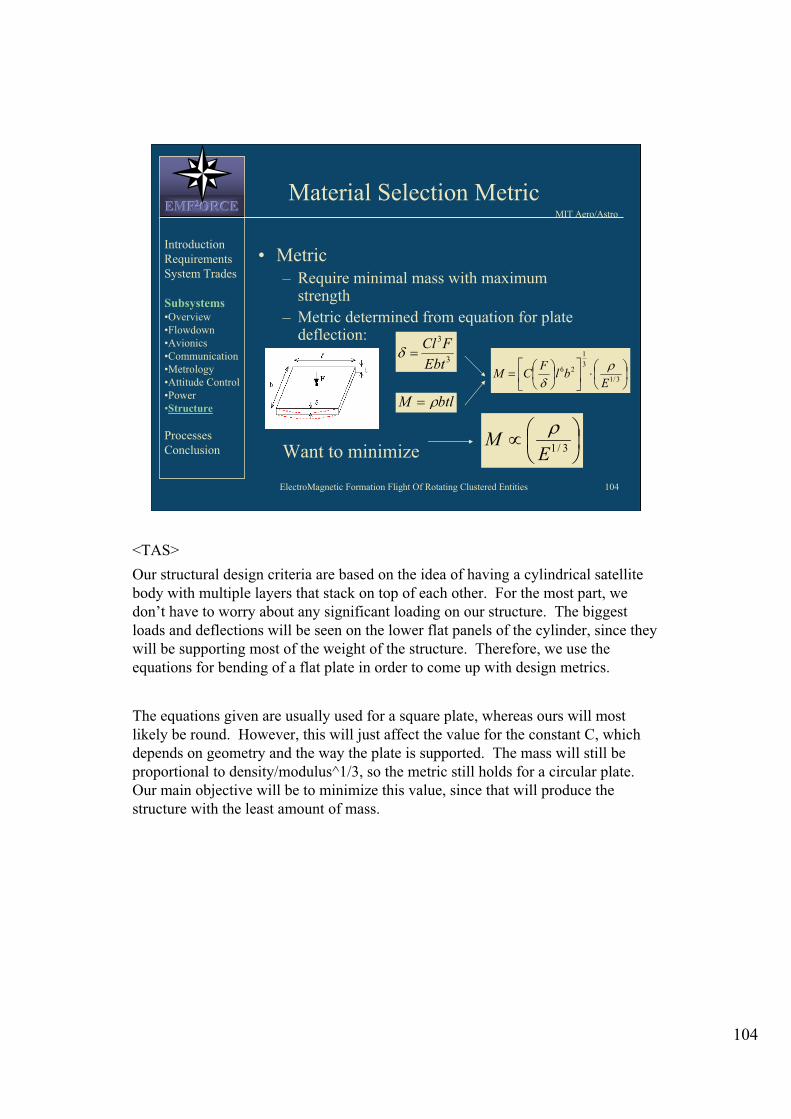
ElectroMagnetic Formation Flight Of Rotating Clustered Entities 104
MIT Aero/Astro EMFEMFEMF222ORCEORCEORCE
Material Selection Metric
• Metric – Require minimal mass with maximum
strength
– Metric determined from equation for plate deflection:
Want to minimize
3
3
Ebt
FCl
btlM
3/1
3
1
26
Ebl
FCM
3/1EM
Introduction
Requirements
System Trades
Subsystems •Overview
•Flowdown
•Avionics
•Communication
•Metrology
•Attitude Control
•Power
•Structure
Processes
Conclusion
<TAS>
Our structural design criteria are based on the idea of having a cylindrical satellite
body with multiple layers that stack on top of each other. For the most part, we
don’t have to worry about any significant loading on our structure. The biggest
loads and deflections will be seen on the lower flat panels of the cylinder, since they
will be supporting most of the weight of the structure. Therefore, we use the
equations for bending of a flat plate in order to come up with design metrics.
The equations given are usually used for a square plate, whereas ours will most
likely be round. However, this will just affect the value for the constant C, which
depends on geometry and the way the plate is supported. The mass will still be
proportional to density/modulus^1/3, so the metric still holds for a circular plate.
Our main objective will be to minimize this value, since that will produce the
structure with the least amount of mass.
104

Materials Downselect MIT Aero/Astro
EMFEMFEMF222ORCEORCEORCE
•Other considerations: - Cost
- Manufacture method
• Final downselect pending further analysis
Introduction
Requirements
System Trades
Subsystems •Overview
•Flowdown
•Avionics
•Communication
•Metrology
•Attitude Control
•Power
•Structure
Processes
Conclusion
Material density (kg/m^ modulus (Gpa) density/E (̂1/3) CTE (microTherm conduct
Aluminum alloy, general 2700 70 0.655 24 190
Magnesium alloy, general 1800 45 0.506 26 80
Titanium alloy, general 4700 110 0.981 8.7 7
Zinc alloy, general 7000 85 1.592 30 105
Stainless steel, Type 400 7700 200 1.317 10.2 24.2
Stainless steel, Type 300 8030 200 1.373 16.6 16.4
Iron superalloy 7920 201 1.352 16.5 17.6
Nickel superalloy 8420 207 1.423 12.4 14.8
ABS polymer, molded 1050 2.4 0.784 90.6 0.15
Acetal copolymer, 30% glass fib. 1610 7.7 0.815 37 0.32
Acrylic 1180 3.3 0.793 72.9 0.2
Polyester, rigid 1650 6.7 0.875 135 0.17
Polycarbonate/PET 1220 2.2 0.938 69.5
ElectroMagnetic Formation Flight Of Rotating Clustered Entities 105
ALS
Shown here is a table of material properties. The table includes several types of
metals and plastics. The parameters of interest here are density, modulus, the
design metric of density/modulus^1/3, coefficient of thermal expansion, and the
thermal conductivity. Note that for plastics, the flexural modulus and not the tensile
modulus is used.
Using only the design metric, Aluminum and magnesium alloys as well as several
types of plastics are the ideal choices. Parameters not taken into consideration here
are cost and ease of manufacture. Further downselect of materials requires further
investigation.
105

ElectroMagnetic Formation Flight Of Rotating Clustered Entities 106
MIT Aero/Astro EMFEMFEMF222ORCEORCEORCE
EM Shielding
• High permeability metals
• Available in foils, sheets, bars, plates
and tubing
• “Sample kit” ~$200
Custom0.080-2.25” dia.Tubing
0.135” and upUp to 10” widePlate
0.015-0.060”24x30”, 36x120”Sheet
0.002-0.010”Up to 16” wideFoil
ThicknessDims.
Introduction
Requirements
System Trades
Subsystems •Overview
•Flowdown
•Avionics
•Communication
•Metrology
•Attitude Control
•Power
•Structure
Processes
Conclusion
ALS
High permeability shielding materials are available in these forms.
106

ElectroMagnetic Formation Flight Of Rotating Clustered Entities 107
MIT Aero/Astro EMFEMFEMF222ORCEORCEORCE
Air Carriage
Introduction
Requirements
System Trades
Subsystems •Overview
•Flowdown
•Avionics
•Communication
•Metrology
•Attitude Control
•Power
•Structure
Processes
Conclusion
• Require low-friction
support system to
simulate 2D
microgravity
• Air bearings provide
best option
• Flat pad air bearing
allows x-, y-translation,
yaw rotation, as shown Flat pad bearing
<DC, AS>
Some sort of system is required to reproduce microgravity in 2 dimensions.
Supporting the system with a cushion of high-pressure CO2 will allow the system to
translate with low friction. A simulated profile of the pressurized cushion can be
seen in the upper right corner. The air bearings can provide the required support,
using onboard CO2 canisters to provide pressurized gas.
107

ElectroMagnetic Formation Flight Of Rotating Clustered Entities 108
MIT Aero/Astro EMFEMFEMF222ORCEORCEORCE
Introduction
Requirements
System Trades
Subsystems •Overview
•Flowdown
•Avionics
•Communication
•Metrology
•Attitude Control
•Power
•Structure
Processes
Conclusion
Flat Pad Air Bearing
Pressure profile
•Creates cushion of air for
frictionless translation and
rotation
•No umbilical; self contained
unit
• Hydrostatic pressure from
tank
•Pressure drops off at edges
of bearing, as shown
<DC, AS, WDF>
Air bearings operate by creating a cushion of air for frictionless translation and
rotation. These systems will be self-contained with replenishable CO2 canisters.
This eliminates the need for an umbilical cord which may cause unwanted forces
acting on the system. The diagram shows how the air pressure drops of at the edges
of the bearing but is mostly constant across the surface of the bearing.
108

ElectroMagnetic Formation Flight Of Rotating Clustered Entities 109
MIT Aero/Astro EMFEMFEMF222ORCEORCEORCE
Air Bearing Trade
Introduction
Requirements
System Trades
Subsystems •Overview
•Flowdown
•Avionics
•Communication
•Metrology
•Attitude Control
•Power
•Structure
Processes
Conclusion
• Require at least three bearings for stability
• Each bearing must support 1/3 of total system weight
• Efficiency factor = 0.3 to account for edge effects
• Force required per bearing:
• Yields
bearingsupplybearingtotal AP
gM
3
bearingbearing
total
A
gMP
3
<DC, AS>
Three air bearings are required to ensure stability. Thus, each bearing must support
1/3 of the total weight of the system. To calculate the required area of each bearing,
the above equation is used with a .3 efficiency factor to account for pressure loss at
the fringes of the bearing. The required supply pressure is then a function of bearing
area only.
109
supply

ElectroMagnetic Formation Flight Of Rotating Clustered Entities 110
MIT Aero/Astro EMFEMFEMF222ORCEORCEORCE
Air Bearings Specifications
Introduction
Requirements
System Trades
Subsystems •Overview
•Flowdown
•Avionics
•Communication
•Metrology
•Attitude Control
•Power
•Structure
Processes
Conclusion
Typical specifications
• Linear accuracy: 10 in/in,
100 in / 36 in
• Rotary accuracy: +/- 1 in TIR
• Linear repeatability: +/- 10 in
• Rotary repeatability: 1 in
52,50033015.8 mm50 mmFP-C-020
28,00022012.5 mm38 mmFP-C-15
17,5008812.5 mm25 mmFP-C-10
Stiffness
(N/mm)
Load
Capacity (N)
Thickness
(mm)
Radius (mm)Part
<DC,AS>
Assuming a 60 psi supply pressure, this table lists the specifications for several sizes
of bearings. General manufacturer specifications are also listed. The smallest air
bearing listed is sufficient to support the expected weight of the system.
110

ElectroMagnetic Formation Flight Of Rotating Clustered Entities 111
MIT Aero/Astro EMFEMFEMF222ORCEORCEORCE
Subsystems Summary
• Flowdown
• Avionics
• Communication
• Metrology
• Attitude Control
• Power
• Structure
Introduction
Requirements
System Trades
Subsystems •Overview
•Flowdown
•Avionics
•Communication
•Metrology
•Attitude Control
•Power
•Structure
Processes
Conclusion
<WDF notes>
This concludes our discussion of the subsystems’ trade analysis. We began by
explaining the flowdown from requirements, which generated each subsystem and
then went to explain the metrics and downselect for the subsystem’s components.
111

MIT Aero/Astro EMFEMFEMF222ORCEORCEORCE
Andre Bosch
Processes Review
Introduction
Requirements
System Trades
Subsystems
Processes •Verification
•Budget
•Config Control
•Timelining
Conclusion
JEU
Welcome to the Processes Review portion of the Trade Analysis and Requirements
Review for Project EMFORCE (ElectroMagnetic Formation Flight Of Rotating
Clustered Entities).
112

ElectroMagnetic Formation Flight Of Rotating Clustered Entities 113
MIT Aero/Astro EMFEMFEMF222ORCEORCEORCE
Processes Overview
• Validation and Verification
• Budget Tracking
• Configuration Control
• Timelining and Project Management
Introduction
Requirements
System Trades
Subsystems
Processes •Verification
•Budget
•Config Control
•Timelining
Conclusion
<BAB WDF>
The goal of the processes team was to develop the procedures which will guide the
project to completion. These procedures include the development of a validation
and verification system. A process for the tracking of budgets both financial budgets
and resource budgets. Also, the creation of a system for configuration control.
Finally, we developed a detailed timeline which will carry the project from present
day to completion in the Spring of 2003.
113

ElectroMagnetic Formation Flight Of Rotating Clustered Entities 114
MIT Aero/Astro EMFEMFEMF222ORCEORCEORCE
Definitions
• Validation: Procedures designed to
demonstrate that a newly received part meets
design specifications as per the design
document. “Getting the right part.”
•Verification: Procedures designed to
demonstrate that a part or system meets
design requirements as per the requirements
document. “Getting the part right.”
Introduction
Requirements
System Trades
Subsystems
Processes •Verification
•Budget
•Config Control
•Timelining
Conclusion
<BAB WDF>
Validation procedures have been developed that will demonstrate that a newly
obtained part meets the design specifications. The essentially means “Getting the
right part”. Validation procedures will be used to make sure components,
subsystems, and the final system meet all the design requirements as specified in the
requirements document.
114

ElectroMagnetic Formation Flight Of Rotating Clustered Entities 115
MIT Aero/Astro EMFEMFEMF222ORCEORCEORCE
Validation Process
• Did we get the right part?
– Machined Parts
• Check critical dimensions and tolerances
– Commercial Off-the-Shelf (COTS)
• Check for compliance with manufacturer’s
specifications
• Check critical dimensions and tolerances
• Document the part as valid
– List all actual dimensions and tolerances
Introduction
Requirements
System Trades
Subsystems
Processes •Verification
•Budget
•Config Control
•Timelining
Conclusion
<BAB, ESS>
Abstract: Parts will need to be either purchased or fabricated for the project’s final product. To ensure a
successful final product it is imperative that a process be in place to validate the quality of the purchased or
fabricated part prior to investment of project resources in this part.
1. Validation for Fabricated Parts.
1.1. Definition. Fabricated parts are parts that will be constructed or implemented by members of the project
at a variety of production facilities. These facilities include but are not limited to laboratories, workshops,
machine shops, and computer labs.
1.2. Validation Process. Fabricated parts will be checked against the specifications and tolerances given to
the fabricator prior to fabrication. Only if the fabricated part meets all specification and tolerances will the part
be validated.
1.3. Documentation. Prior to inclusion in a subsystem, every fabricated part must be verified and documented
as verified on CDIO Form 23-212.
2. Validation for Purchased Parts
2.1. Definition. Purchased parts are parts that are purchased by members in the group from a variety of
sources. These sources include but are not limited to companies, manufacturers, and stores.
2.2. Validation Procedure. Purchased parts will be checked against the specifications and tolerances given
by the entity from which they come. Only if the purchased part meets all specifications and tolerances will the
part be validated.
2.3. Documentation. Prior to inclusion in a subsystem, every purchased part must be verified and
documented as verified on CDIO Form 23-211.
2.4. Non-Compliance. Purchased parts that do not meet the specification of the entity from which they are
purchased will be returned to the entity from which they are purchased for a full refund. Non-compliance will
be documented on CDIO Form 23-291.
115
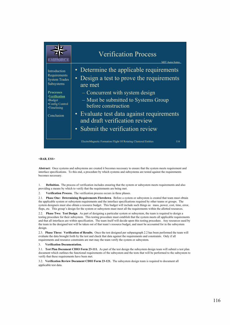
ElectroMagnetic Formation Flight Of Rotating Clustered Entities 116
MIT Aero/Astro EMFEMFEMF222ORCEORCEORCE
Verification Process
• Determine the applicable requirements
• Design a test to prove the requirements are met
– Concurrent with system design
– Must be submitted to Systems Group before construction
• Evaluate test data against requirements and draft verification review
• Submit the verification review
Introduction
Requirements
System Trades
Subsystems
Processes •Verification
•Budget
•Config Control
•Timelining
Conclusion
<BAB, ESS>
Abstract: Once systems and subsystems are created it becomes necessary to ensure that the system meets requirement and
interface specifications. To this end, a procedure by which systems and subsystems are tested against the requirements
becomes necessary.
1. Definition. The process of verification includes ensuring that the system or subsystem meets requirements and also
providing a means by which to verify that the requirements are being met.
2. Verification Process. The verification process occurs in three phases.
2.1. Phase One: Determining Requirements Flowdown. Before a system or subsystem is created that team must obtain
the applicable system or subsystem requirements and the interface specifications required by other teams or groups. The
system designers must also obtain a resource budget. This budget will include such things as: mass, power, cost, time, error,
flops, etc. This group’s design for the system or subsystem must meet all the requirements within the allotted resources.
2.2. Phase Two: Test Design. As part of designing a particular system or subsystem, the team is required to design a
testing procedure for their subsystem. This testing procedure must establish that the system meets all applicable requirements
and that all interfaces are within specification. The team itself will decide upon this testing procedure. Any resources used by
the team in the designed test will be taken out of that team’s resource budget, and must be accounted for in the subsystem
design.
2.3. Phase Three: Verification of Results. Once the test designed per subparagraph 2.2 has been performed the team will
evaluate the data brought forth by the test and check that data against the requirements and constraints. Only if all
requirements and resource constraints are met may the team verify the system or subsystem.
3. Verification Documentation.
3.1. Test Plan Document CDIO Form 23-111. As part of the test design the subsystem design team will submit a test plan
document which outlines the functional requirements of the subsystem and the tests that will be performed to the subsystem to
verify that these requirements have been met.
3.2. Verification Review Document CDIO Form 23-121. The subsystem design team is required to document all
applicable test data.
116

ElectroMagnetic Formation Flight Of Rotating Clustered Entities 117
MIT Aero/Astro EMFEMFEMF222ORCEORCEORCE
Budgets Overview
• Budgets for cost, mass, power, labor,
volume, FLOPs (Floating-point
Operations per Second), and Error will
be tracked
• Sub-teams manage their own budgets
• Weekly reports to the Systems Team
Introduction
Requirements
System Trades
Subsystems
Processes •Verification
•Budget
•Config Control
•Timelining
Conclusion
<ESS, WDF>
In order to ensure that the system is meeting the specified design constraints it will
be important to track various budgets. Official control of budget information is
placed in the hands of the System’s Team. The system’s team will assign budgets to
each sub-team as they see fit. Sub-teams will be responsible for managing their own
budgets and reporting non-compliance to the System’s Team.
117

ElectroMagnetic Formation Flight Of Rotating Clustered Entities 118
MIT Aero/Astro EMFEMFEMF222ORCEORCEORCE
Tracking Procedures
• Weekly Updates for all budgeted items
Sample Cost Budget Plot vs. Time
0
10000
20000
30000
40000
50000
60000
13-Feb-
2002
24-May-
2002
1-Sep-
2002
10-Dec-
2002
20-Mar-
2003
28-Jun-
2003
Pro
je ct
C o
st
(U S
$)
Used Budget
Assigned Budget
Total Budget
Introduction
Requirements
System Trades
Subsystems
Processes •Verification
•Budget
•Config Control
•Timelining
Conclusion
<WDF>
Using an Excel Spreadsheet the System’s team will be able to quickly enter in each
Sub-team’s current budget data and get instant feedback on budget status for all
parameters. This includes a week by week plot of all tracked items to allow
observance of spending trends. All reallocations of budget numbers must be decided
by the Systems Team. Plot shows a sample plot of the project cost versus time. This
plot has the actual value used, the amount that has been allocated and the total
budget. A similar plot is generated for every parameter (mass, power, labor and
volume).
118

ElectroMagnetic Formation Flight Of Rotating Clustered Entities 119
MIT Aero/Astro EMFEMFEMF222ORCEORCEORCE
Tracking Procedures
• FLOPS budgets depend on operating modes
– Startup, steady control, formation change
• Error tracking consists of holding control tolerances
– Sources of error in position and angular rate
• Accuracy of metrology
• Accuracy of control law
• Stability of electromagnets
Introduction
Requirements
System Trades
Subsystems
Processes •Verification
•Budget
•Config Control
•Timelining
Conclusion
<WDF>
FLOPS budgets will depend on operating state, and will be set by the hardware purchased. It will be important for software and avionics to be sure to test all possible combinations of computing modes to ensure that FLOPs usage remains under budget.
Error tracking currently only consists of position and angular rate errors. These errors can be results of accuracy problems in the metrology equipment or software. Stability of the electromagnets and there properties. The accuracy of the electromagnetic and system dynamics models.
119

ElectroMagnetic Formation Flight Of Rotating Clustered Entities 120
MIT Aero/Astro EMFEMFEMF222ORCEORCEORCE
Configuration Control
• One official version of all group documents
– Essential for efficiency and mission completion
– Eliminates confusion over current version of documents
• Major documents tracked by Chief Systems Engineer
• Other documents tracked by Systems Group
Introduction
Requirements
System Trades
Subsystems
Processes •Verification
•Budget
•Config Control
•Timelining
Conclusion
<ESS>
PROCESSES DOCUMENT 22-1
CONFIGURATION CONTROL
Purpose: This document will describe the process by which project and subproject
configuration will be controlled by the proper authorities.
Abstract: Configuration control is essential in systems engineering applications.
All groups and teams must be working with the most current information, but it is
essential that this information is the same for all teams. The Chief Systems
Engineer will place major documents under configuration control. The Systems
Group will control smaller documents.
120

ElectroMagnetic Formation Flight Of Rotating Clustered Entities 121
MIT Aero/Astro EMFEMFEMF222ORCEORCEORCE
Tracking Interfaces
• How the subsystems are mated
together into the final project
• Documentation of all subsystem inputs
and outputs is required
– Power connections
– Information flow
– Structural attachments
• Critical to success of final project
Introduction
Requirements
System Trades
Subsystems
Processes •Verification
•Budget
•Config Control
•Timelining
Conclusion
<ESS>
PROCESSES GROUP INSTRUCTION 22-11
INCLUSION OF INTERFACE SPECIFICATIONS IN ARCHITECTURE DESIGN
1. The most important aspect of systems integration during the latter stages of the
systems design project will be the interfaces between the various subsystems.
Therefore, it is critical that all inputs to and outputs from each subsystem are well
documented.
2. When designing an abstract for a subsystem, the interfaces must be summarized
in an interface specification document (CDIO Form 22-112). Types of interfaces
may include but are not limited to:
a. Physical design and specification of power connections
b. Electronic Communications between various subsystems
c. Structural connections and attachments from the subsytems to the main structure
3. This interface documentation should be included in the design of the final
architecture, which will be included in all formal reviews.
121

ElectroMagnetic Formation Flight Of Rotating Clustered Entities 122
MIT Aero/Astro EMFEMFEMF222ORCEORCEORCE
Preliminary Design Phase Execution
Objectives
Introduction
Requirements
System Trades
Subsystems
Processes •Verification
•Budget
•Config Control
•Timelining
Conclusion
Team Goals:
• Assurance of task completion – Weekly briefing to team by systems group
• Provide warning of potential problems ahead– Consistent weekly updates to timeliner
• Maintain strong communication lines – Avoids misconceptions on progress and
needs
• Sustained time commitment
<JEU>
For any plan, it’s important to consider problems encountered before and to take
steps to prevent them from occurring again. There were many problems with
Timelining the project encountered during the first six weeks.
In this capacity, the Processes Group proposes the following four Team Goals.
1. Assurance of Task Completion
The briefing gives an opportunity for the whole Team to get on the
same page, so to speak.
2. Provide Warning of Potential Problems Ahead
Consistent updates to the TimeLiner allow for consistent checks on
progress, and thus allows the Team to be informed of potential future problems
with task completion and ensures the issue is addressed immediately.
3. Maintain Strong Communication Lines
Provides open forum for group interaction to avoid problems with
task dependencies.
4. Sustained Time Commitment
Each team member should plan on placing a sustained emphasis
(time and effort) on their portion of the project to accomplish all tasks on schedule.
122

ElectroMagnetic Formation Flight Of Rotating Clustered Entities 123
MIT Aero/Astro EMFEMFEMF222ORCEORCEORCE
Preliminary Design Phase
Organizational Chart
EMTeam (2)
RWA Team (2)
EM Hardware Group
Avionics Team (2)
Control Team (2)
Attitude Control Group
Metrology Team (2)
Comm/Ops Team (2)
Formation Flight Group
Str/Pwr Team (3)
Structures and Power Group
Systems Group
Avionics Team •Electronics
•Power
•Computer Hardware
Control Team •Control
•Software
Metrology Team •Relative Position
•Angular
•Data to ACS
Comm/Ops Team •Comm to Ground
•Comm b/w Vehicles
•Testing Procedures
•Documentation
Structures Team •Detailed Design
•Physical Interfaces
EM, RWA Teams •Design
•Trades
•Implementation
Introduction
Requirements
System Trades
Subsystems
Processes •Verification
•Budget
•Config Control
•Timelining
Conclusion
<JEU, ESS, WDF>
In the next week, the project will move into the Preliminary Design Phase (PDP). In
order to ensure the progress of the project through the PDP the Processes team
recommends that the class be divided into the following groups and teams. There
will be four groups each of which will have on representative on the System’s
Group. These Groups are: EM Hardware, Attitude Control Group, Formation Flight
Group, and the Structures Group. These groups will then be furthered divided teams
whose specific responsibilities are all detailed above
123

ElectroMagnetic Formation Flight Of Rotating Clustered Entities 124
MIT Aero/Astro EMFEMFEMF222ORCEORCEORCE
Introduction
Requirements
System Trades
Subsystems
Processes •Verification
•Budget
•Config Control
•Timelining
Conclusion
Timeline To Preliminary
Design Review (PDR)
Task Name Address TARR Action Items
Flowdown Requirements
Define Interfaces
Subsystem Design
Fabrication/Procurement Plans
Procurement Order Deadline
Prototyping
Tests & Model Comparisons
Alter Hardware Designs
PDR Preparation and PDR
03/21 04/02
04/01 04/04
04/01 04/05
04/02 04/16
04/01 04/09
04/16
04/18 04/30
04/23 04/30
04/23 04/30
04/23 05/07
W1 W2 W3 W4 W5 W6 W7 W8 W9
<JEU>
The main focus of the Plan to Execute the Preliminary Design Phase (PDP) is a projected timeline to the PDR on 7 May.
This timeline lists major tasks to be accomplished by each Sub-System Team (or Group). The tasks differ in Developing their Sub-System Designs. These diverging tasks are included on a separate page (and backup slide).
The Gantt Chart beside the Major Task List shows the proposed time allocation for each task for each group. Many things must be run in parallel within each group for the tasks to be accomplished on time. There is some flexibility within groups to assign more detailed timelines and tasks to individual members, but it is absolutely critical that each individual and group stay aware of the overall timeline. This is to be directed and verified by the Systems Group.
124

ElectroMagnetic Formation Flight Of Rotating Clustered Entities 125
MIT Aero/Astro EMFEMFEMF222ORCEORCEORCE
Introduction
Requirements
System Trades
Subsystems
Processes •Verification
•Budget
•Config Control
•Timelining
Conclusion
Task Name Implement
Sub-System Testing
Assemble Prototype
Test Prototype
CDR Preparation
CDR
Aug Sep Oct Nov Dec
Preliminary Design Review to
Critical Design Review
<JEU>
Finally, it’s important to look ahead to the other major milestones, such as CDR and
AR. This is a timeline from the completion of the Preliminary Design Review to
the wrap-up of the Critical Design Review in November 2002. There is not much
detail because much has yet to become apparent. However, there are some things
that can be considered now as major sections of the project. These are shown above
in the task list and Gantt chart. The Gantt chart describes the proposed timeline of
events as seen currently.
The Long-Term Procurement phase of the project occurs over Summer break 2002
(May 2002 – August 2002).
Note: Past the PDR, all of the dates are rough estimates.
125

ElectroMagnetic Formation Flight Of Rotating Clustered Entities 126
MIT Aero/Astro EMFEMFEMF222ORCEORCEORCE
Introduction
Requirements
System Trades
Subsystems
Processes •Verification
•Budget
•Config Control
•Timelining
Conclusion
Task Name Operate
Implementation Cont
Initial Test at MIT
Field Operations
AR Preparation
AR
Jan Feb Mar Apr May
Critical Design Review to
Acceptance Review (Feb - May ’03)
<JEU>
Finally, it’s important to look ahead to the other major milestones, such as CDR and
AR. This is a timeline from the completion of the Critical Design Review to the
Acceptance Review in May 2003. There is not much detail because much has yet to
become apparent. However, there are some things that can be considered now as
major sections of the project. These are shown above in the task list and Gantt
chart. The Gantt chart describes the proposed timeline of events as seen currently.
The Flight Hardware Development Phase of the project occurs between December
2002 and the beginning of February 2003.
Note: Past the PDR, all of the dates are rough estimates.
126

ElectroMagnetic Formation Flight Of Rotating Clustered Entities 127
MIT Aero/Astro EMFEMFEMF222ORCEORCEORCE
Conclusion and Summary
• Motivations for EMFF
• Requirements and Scaling
• Systems Trade Analysis
• Subsystem Trade Analysis
• Processes
– Timeline set through PDR
– Formal configuration control applied to
the Requirements Document
Introduction
Requirements
System Trades
Subsystems
Processes
Conclusion
<BAB, ESS, WDF >
We began with an explanation of the details and motivation behind our project. We
then detailed the requirements and constraints that our design will be verified
against. An overall System’s Trade Analysis was presented which detailed many of
the key trades for this design. We then listed our metrics and recommended
components for each of the various subsystems. Finally we detailed the processes
and procedures that will be used to carry through project forward towards
completion.
127

ElectroMagnetic Formation Flight Of Rotating Clustered Entities 128
MIT Aero/Astro EMFEMFEMF222ORCEORCEORCE
Questions
?
Introduction
Requirements
System Trades
Subsystems
Processes
Conclusion
< ESS, WDF>
We would like to thank all of you for sharing your valuable time with us today. We
will now take questions from the audience.
128

MIT Aero/Astro EMFEMFEMF222ORCEORCEORCE
Back-Up Slides
<JEU>
This is the backup slide section of the presentation. These slides are only meant to
be shown should a question be raised that these slides can help clarify.
129

ElectroMagnetic Formation Flight Of Rotating Clustered Entities 130
MIT Aero/Astro EMFEMFEMF222ORCEORCEORCE
Accelerometers & Gyros
• Accelerometers
– Single axis
– High accuracy
– Size: ~4x4x7 mm, .5 g
– Price: $425
• Gyros
– Small, lightweight
– Price: $88
Introduction
Requirements
System Trades
Subsystems •Flowdown
•Avionics
•Communication
•Metrology
•Attitude Control
•Power
•Structure
Processes
Conclusion
<AA>
Acceleration information will help to make the system controllable. This is desirable since the system will be inherently unstable.
Accelerometers are highly accurate scientific measurement devices.
The gyro shown is an off-the-shelf, low accuracy, angular acceleration measurement device.
130

ElectroMagnetic Formation Flight Of Rotating Clustered Entities 131
MIT Aero/Astro EMFEMFEMF222ORCEORCEORCE
Battery Downselect: Comparison
3.353.753.952.853.353.452.95100%TOTAL
3
4
2
3
5
3
5
2
4421555%Discharge
44343310%Mass
34233330%E-Density
54543220%Cycle Life
55244210%Memory
Effects
2234445%Safety
Factor
34235315%Voltage
Profile
4343555%Cost
Alk
ali
ne-
2
Wei
gh
t
Alk
ali
ne-
1
NiM
H
NiC
ad
Li-
ion
Lit
hiu
m
Zn
-CIntroduction
Requirements
System Trades
Subsystems •Flowdown
•Avionics
•Communication
•Metrology
•Attitude Control
•Power
•Structure
Processes
Conclusion
<SJS>
Cost: A lower cost will receive a higher rating.
Voltage Profile: Flatter voltage curves will receive a lower score and higher scores
will be given to those with the more constant sloped curve profiles.
Safety Factor: Those batteries with known safety concerns will receive lower ratings.
Memory Effects: The greater the memory loss, the lower the score.
Lifetime: A longer lifetime is desired.
Energy Density: A high energy density is the primary concern in selecting battery type.
Mass: We wish to keep the mass at a minimum.
Self-Discharge Rate: The lower the discharge rates, the higher the batteries will score.
<SJS>
131

ElectroMagnetic Formation Flight Of Rotating Clustered Entities 132
MIT Aero/Astro EMFEMFEMF222ORCEORCEORCE
Subsystem Task Breakdown
Task Name
Develop a an Optimal Design
EM and RWA Design
EM dipole configurations and hardware
Size RWA to meet requirements within bud
Structure and Air Carriage
Define mechanical interfaces for subsystem
Minimize frame mass, etc
Model and measure system inertias
Model System
Complete CAD and FEM models of system
Integrate model of structure prototype
Longer-duration Operations Air Carriage
Communications and Operations
Create the operations plan
Wireless and autonomous operation of 'Sats
Power, Avionics, and Software
Electrical power system
Define electrical interfaces
Optimize system electrical efficiency
Battery hazard control
Analog signal conditioning
Touch temperature control
Analog device drivers, etc
Onboard software device drivers
Real-time control software operating system
Data handling and temporary storage
Control loop design
Systems
Budget Development
Detailed Timelining
PDR Presentation Preparation
Verification and Validation Plan
Configuration Management of CAE Drawin
Documentation
W1 W2 W3 W4 W5 W6 W7 W8 W9 W10
Introduction
Requirements
System Trades
Subsystems
Processes •Verification
•Budget
•Config Control
•Timelining
Conclusion
<JEU>
This is the timeline to PDR broken down by required subsystem tasks. Essentially,
these describe the major tasks that need to be accomplished to develop an optimal
design for each subsystem.
132

ElectroMagnetic Formation Flight Of Rotating Clustered Entities 133
MIT Aero/Astro EMFEMFEMF222ORCEORCEORCE
Detailed Timeline to AR
ID Task Name
1 Concieve and Design
2 Concieve
3 Conceptualization
4 TARR
5 Design
6 Prototype
7 PDR
8 Long Lead Procurement
9
10 Implement
11 Sub-System Testing
12 Assemble Prototype
13 Test Prototype
14 CDR Preparation
15 CDR
16 Flight Hardware
17
18 Operate
19 Implementation Continuation
20 Initial Test at MIT
21 Field Operations in Denver
22 AR Preparation
23 AR
0%
0%
0%
0%
0%
0%
0%
0%
0%
0%
0%
0%
0%
0%
0%
0%
0%
0%
0%
0%
0%
03101724031017243107142128051219260209162330071421280411182501081522290613202703101724010815222905121926020916230209162330061320270411182
Feb '02Mar '02 Apr '02 May '02 Jun '02 Jul '02 Aug '02 Sep '02 Oct '02 Nov '02 Dec '02 Jan '03 Feb '03Mar '03 Apr '03 May '0
Introduction
Requirements
System Trades
Subsystems
Processes •Verification
•Budget
•Config Control
•Timelining
Conclusion
<JEU>
This Gantt chart demonstrates the timeline of major tasks and phases of the project
from start to completion (designated by the approximate date of the Acceptance
Review).
133