TRACKING WITH A PAN-TILT-ZOOM CAMERA FOR AN ACC …TRACKING WITH A PAN-TILT-ZOOM CAMERA FOR AN ACC...
6
TRACKING WITH A PAN-TILT-ZOOM CAMERA FOR AN ACC SYSTEM X. Clady, F. Collange,F. Jurie andP. Martinet LASMEA - UMR 6602 du CNRS - Blaise Pascal University 24 avenue des Landais 63177 Aubi` ere Cedex FRANCE e-mail: Firstname.Name @lasmea.univ-bpclermont.fr ABSTRACT In this paper, visual perception of frontal view in intelli- gent cars is considered. A Pan-Tilt-Zoom (PTZ) camera is used to track preceding vehicles. The aim of this work is to keep the rear view image of the target vehicle stable in scale and position. An efficient real time tracking algorithm is integrated. It is a generic and robust approach, particularly well suited for the detection of scale changes. The camera rotations and zoom are controlled by visual servoing. The methods presented here were tested on real road sequences within the VELAC demonstration vehicle. Experimental re- sults show the effectiveness of such an approach. The per- spectives are in the development of a visual sensor com- bining a PTZ camera and a standard camera. The standard camera has small focal length and is devoted to an analysis of the whole frontal scene. The PTZ camera gives a local view of this scene to increase sensor range and precision. 1. INTRODUCTION Computer vision for driving assistance systems has attracted considerable attention over the last decade. These systems offer potential solutions to the problems caused by the in- crease in world road traffic (particularly in industrialized countries): pollution, traffic congestion, safety... They aim to help drivers prevent and avoid collisions and to alleviate traffic congestion. Within this framework, several devices[13] for intelli- gent vehicles are being developed by research laboratories and car manufacturers: “Stop and Go” devices, stop and start vehicles in con- gestion. “Platooning”, to create trains of vehicles (several ve- hicles follow the trajectory of a car-leader). “Adaptive Cruise Control” (ACC)[1, 14], automati- cally controls the speed of a vehicle in order to main- tain safety distances relative to preceding vehicles. “CollisionWarning or Avoidance”, informs or replaces the driver when accident risks are detected. The LASMEA is involved in such projects and research has been undertaken in order to implement an ACC device on the VELAC 1 experimental vehicle. Within this frame- work, algorithms for detecting and tracking the roads, with or without lanes, and the preceding vehicles provided with visual landmarks, have been developed using monocular vi- sion, and tested successfully in real conditions [1]. How- ever these solutions present some limitations. One of these relates to the use of visual land-marks on the detected vehi- cles. Moreover, the sensor range is limited to 60 meters by the resolution of the camera (which must have a short fo- cal distance to capture all the frontal scene). This limitation means that distant obstacles cannot be detected, in particu- lar those with slow kinematics. Therefore, the addition of a camera provided with a zoom could solve this problem. Moreover, this camera can be focused on a particular vehi- cle, the most dangerous, in order to determine its kinematic characteristics more precisely. This latter application is the main subject of this article. It describes a sensor system to track the rear view of a ve- hicle with a PTZ camera. This camera, controlled for zoom and pan tilt angles, represents the hardware part of the sys- tem. It provides image sequences of the car to a tracking algorithm. This algorithm is the software part of the sen- sor system. It computes the position, the orientation and the size of the target in the image. This data is used to control the PTZ camera, in order to keep the target centered in the image with a constant size. The originality of the algorithm is its ability to track any kind of patterns in real time video, on low cost hardware. These characteristics make the sensor system very efficient for real time applications like ACC. Moreover, it runs with- out land-marks. This article comprises three sections. The first section describes the context of the application. It explains how the PTZ camera is combined with a standard camera to make up the sensor equipment. The second section presents the tracking algorithm and the control law. The experiments were conducted from inside the demonstration VELAC ve- hicle and are presented in the third section. 1 VELAC, V´ ehicule Exp´ erimental du LASMEA pour l’Aide ` a la Con- duite (see fig. 9).
Transcript of TRACKING WITH A PAN-TILT-ZOOM CAMERA FOR AN ACC …TRACKING WITH A PAN-TILT-ZOOM CAMERA FOR AN ACC...

TRACKING WITH A PAN-TILT-ZOOM CAMERA FOR AN ACC SYSTEM
X. Clady, F. Collange, F. Jurie and P. Martinet
LASMEA - UMR 6602 du CNRS - Blaise Pascal University24 avenue des Landais 63177 Aubiere Cedex FRANCEe-mail: [email protected]
ABSTRACT
In this paper, visual perception of frontal view in intelli-gent cars is considered. A Pan-Tilt-Zoom (PTZ) camera isused to track preceding vehicles. The aim of this work is tokeep the rear view image of the target vehicle stable in scaleand position. An efficient real time tracking algorithm isintegrated. It is a generic and robust approach, particularlywell suited for the detection of scale changes. The camerarotations and zoom are controlled by visual servoing. Themethods presented here were tested on real road sequenceswithin the VELAC demonstration vehicle. Experimental re-sults show the effectiveness of such an approach. The per-spectives are in the development of a visual sensor com-bining a PTZ camera and a standard camera. The standardcamera has small focal length and is devoted to an analysisof the whole frontal scene. The PTZ camera gives a localview of this scene to increase sensor range and precision.
1. INTRODUCTION
Computer vision for driving assistance systems has attractedconsiderable attention over the last decade. These systemsoffer potential solutions to the problems caused by the in-crease in world road traffic (particularly in industrializedcountries): pollution, traffic congestion, safety... They aimto help drivers prevent and avoid collisions and to alleviatetraffic congestion.
Within this framework, several devices[13] for intelli-gent vehicles are being developed by research laboratoriesand car manufacturers:
� “Stop and Go” devices, stop and start vehicles in con-gestion.
� “Platooning”, to create trains of vehicles (several ve-hicles follow the trajectory of a car-leader).
� “Adaptive Cruise Control” (ACC)[1, 14], automati-cally controls the speed of a vehicle in order to main-tain safety distances relative to preceding vehicles.
� “CollisionWarning or Avoidance”, informs or replacesthe driver when accident risks are detected.
The LASMEA is involved in such projects and researchhas been undertaken in order to implement an ACC deviceon the VELAC1 experimental vehicle. Within this frame-work, algorithms for detecting and tracking the roads, withor without lanes, and the preceding vehicles provided withvisual landmarks, have been developed using monocular vi-sion, and tested successfully in real conditions [1]. How-ever these solutions present some limitations. One of theserelates to the use of visual land-marks on the detected vehi-cles. Moreover, the sensor range is limited to 60 meters bythe resolution of the camera (which must have a short fo-cal distance to capture all the frontal scene). This limitationmeans that distant obstacles cannot be detected, in particu-lar those with slow kinematics. Therefore, the addition ofa camera provided with a zoom could solve this problem.Moreover, this camera can be focused on a particular vehi-cle, the most dangerous, in order to determine its kinematiccharacteristics more precisely.
This latter application is the main subject of this article.It describes a sensor system to track the rear view of a ve-hicle with a PTZ camera. This camera, controlled for zoomand pan tilt angles, represents the hardware part of the sys-tem. It provides image sequences of the car to a trackingalgorithm. This algorithm is the software part of the sen-sor system. It computes the position, the orientation and thesize of the target in the image. This data is used to controlthe PTZ camera, in order to keep the target centered in theimage with a constant size.
The originality of the algorithm is its ability to track anykind of patterns in real time video, on low cost hardware.These characteristics make the sensor system very efficientfor real time applications like ACC. Moreover, it runs with-out land-marks.
This article comprises three sections. The first sectiondescribes the context of the application. It explains how thePTZ camera is combined with a standard camera to makeup the sensor equipment. The second section presents thetracking algorithm and the control law. The experimentswere conducted from inside the demonstration VELAC ve-hicle and are presented in the third section.
1VELAC, Vehicule Experimental du LASMEA pour l’Aide a la Con-duite (see fig. 9).
2. CONTEXT OF THE APPLICATION
Three perception functions are essential in ACC applica-tion: road and lane detection (in order to locate the exper-imental vehicle), preceding vehicles detection and locationand finally, tracking of the most dangerous vehicle2 [1]. Thekinematic characteristics (i.e. speed and relative position)of dangerous vehicles can be computed by combining thesethree functions.
These perception tasks can be efficiently achieved usingvideo cameras. Despite the fact that cameras cannot directlyperceive the 3D environment, they have numerous advan-tages. They can provide very useful information about thestructure of the environment like the position of the lanesor the position of obstacles and surrounding vehicles. Suchequipment is generally not very heavy and not very expen-sive, and can therefore be easily embedded inside a vehicle.
PTZ cameras have a variable focal length. This is agreat advantage for A.C.C. applications. Indeed, the aver-age braking distance for a vehicle running at a speed of 100km/h is 100 meters and it can reach 200 meters at 140 km/h.Thus, for applications on motor-ways, it is necessary to de-tect vehicles as far ahead as possible. An acceptable limitwould be around 300 meters (in a straight line). The PTZcamera is the only equipment satisfying these constraints atthe moment.
But an increase in the camera focal length limits the vi-sual field. Targets can leave the field of view, especially inturns or declivities of the road.
The originality of the approach presented is to combinea short fixed focal length camera with the PTZ camera toovercome these limitations. The PTZ camera offers a lo-cal but directional vision while the standard camera offers aglobal vision of the frontal scene.
The first camera will be used to detect lanes, to locatethe vehicle and to detect vehicles stated as potentially dan-gerous (by taking into account the distances of the frontalvehicles and their positions on the road lanes) within thelimits of its visual field.
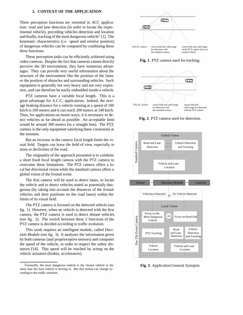
The PTZ camera is focused on the detected vehicle (seefig. 1). However, when no vehicle is detected with the firstcamera, the PTZ camera is used to detect distant vehicles(see fig. 2). The switch between these 2 functions of thePTZ camera is decided according to traffic evolution.
This work requires an intelligent module, called Deci-sion Module (see fig. 3). It analyzes the information givenby both cameras (and proprioceptive sensors) and computesthe speed of the vehicle, in order to respect the safety dis-tances [14]. This speed will be reached by acting on thevehicle actuators (brakes, accelerators).
2Generally, the most dangerous vehicle is the closest vehicle in thesame lane the host vehicle is driving in. But this notion can change ac-cording to the traffic situation.
����������������������������
����������������������������
the standard camera
vision field and valid rangefor detection with
vision field and valid rangeof the PTZ camera focus ontracked vehicle
VELAC vehicle
Fig. 1. PTZ camera used for tracking.
����������������������������
����������������������������
VELAC vehicle vision field and valid rangefor detection with
vision field andvalid range for detection with the PTZ camera the standard camera
Fig. 2. PTZ camera used for detection.
Vehicle(s) Detected No Vehicle Detected
ControlsDecision ModuleSensor
Road and Lane
and Tracking
Vehicle Detection
Detection
Global Vision
Location
Focus on Road EndOR
PTZ Tracking
Vehicle
Road
Detectionand Lane
Vehicle and Lane
VehicleDetection
and Tracking
Most DangerousFocus on the
Vehicle
IF
Local Vision
Stan
dard
Cam
era
Pan-
Tilt
-Zoo
m C
amer
a
Vehicle and LaneLocation
Location
Fig. 3. Application General Synopsis

3. PTZ TRACKING
In this application, tracking an object means tracking a 2Dpattern in image sequences, in order to keep it along the op-tical axis of the camera with a constant scale. In this section,the tracking algorithm is first presented. Second, control ofthe camera is explained.
3.1. The tracking algorithm
The algorithm related in this section makes it possible toestimate the displacement (location, scale and orientation )of a 2D image pattern. It is based on the general frameworkproposed by Hager and Belhumeur [6].
It consists in relating the displacement of a referencepattern to intensity variations in a region of interest (ROI)centered on the pattern. This relation, supposed to be linear,is included in a matrix called theinteraction matrix. Thismatrix is computed during a learning stage. The follow-ing paragraphs show how this matrix is defined and used totrack the pattern. More details and results can be found in[2].
3.1.1. Definitions
To represent the position of the ROI (including pattern) andits content, two vectors are defined: a parameters vectorE and a pattern vector I. In this article, ROIs are ellip-tic and their position vectors contain five parameters: theposition of the center (Xc, Yc), the orientation (�) and thelargest/smallest axis (R1,R2) lengths (see Fig. 4). VectorI is obtained by sampling the pattern included in the ROI.The samples are distributed on concentric ellipses deducedby scaling the ROI edges, in order to keep their density con-stant throughout the ROI (in Fig. 5, dots represent the pointswhere samples are taken). This representation of patterns ina local reference is independent of their position, orientationand scale in the image.
θ
Xc
Yc
R2
R1
Fig. 4. The five parameters Fig. 5. Pattern vectors
With these definitions, a reference pattern vector cor-responding to the samples of the reference pattern is com-puted. By writing �I = Iref � Icur, �I is null when thecurrent pattern is equal to the reference pattern. An optimalparameter forEopt leading to this configuration needs to beestimated.
The knowledge of a function f defined by:
�E = Eopt � Ecur = f(�I)
, Eopt = Ecur + f(�I)(1)
is a powerful tool to track patterns. This function can beapproximated by the first order term of its Taylor develop-ment, and can be written under the following matrix form:
�ET= A:�IT (2)
where ET denotes the transposition of E.This matrix A is called the interaction matrix.
-+ +
-
∆ Ι
-+
Iref
Image Sequences
E
Iref
∆ Ε
Pattern Vector
Tra
ckin
g St
age Ep
Ic
E New Parameter Vector
∆ ΕL
earn
ing
Stag
eFOR
SamplingPattern Vector
Equation System
Corrective ParameterVector
A
Parameters Correction
Pattern Vector Sampling
Prediction Step
Image Acquisition System
Reference Image
Eref
Parameter Vector
IrefReferencePattern Vector
Ic
Difference Pattern Vector∆ Ι
Current Pattern Vector
Predict Parameter Vector
Reference Image
Equation System Building
System Resolution (SVD)
Pattern Vector Sampling
Pattern Selection
Interaction Matrix A Parameter Vector ESequences
Interaction Matrix Multiplication
Adjustment
Parameter VectorPerturbation
i i
iE
Eref
Fig. 6. Tracking Process Scheme
3.1.2. Estimation and use of the Interaction Matrix
The interaction matrix is obtained in a learning stage. Atthe beginning of this stage the ROI, including the referencepattern, is (manually or automatically) selected. Then, it israndomly modified: small perturbations are applied to each

of its five parameters. Each time, the pattern vectors corre-sponding to this new ROI are sampled and kept for furthertreatments.
When a number of perturbations superior to the num-ber of samples (giving a system with more equations thanunknowns), a least square approximation of A can be esti-mated by using a Singular Values Decomposition.
Then, the use of the interaction matrix is very straight-forward. Multiplied by the difference between the currentand the reference pattern vectors, it gives an estimation ofthe transformation aligning the current ROI with the loca-tion of the reference pattern in the current image (see eq.2).
3.1.3. Conclusions about the tracking algorithm
This tracking algorithm presents the following advantages:
� it is a generic approach: any kind of pattern can betracked after being learnt (in a relatively short time -see section 3.3),
� it runs in real time: the computation consists in a sin-gle matrix multiplication,
� it tracks small displacements in location, scale andorientation with great precision,
� it could be enlarged to large displacements by addinga prediction step.
This algorithm is well suited for the application presentedwhere any kind of vehicle needs to be tracked in real time.Current vehicles, apart from motor-cycles, often present a2D surface in their rear view. A precise computation ofsmall displacements is needed to control the PTZ camera.
3.2. Control law
The control of the PTZ camera obtained through by a con-ventional visual servoing approach. The information pro-vided by the tracking algorithm concerns the ellipse param-eters. One way is to use the work conducted in [11] wherethe ellipse parameters are used to control 5 degrees of free-dom (d.o.f). As the sensor equipment has only 3 d.o.f, asimpler method has been chosen.
Here, the sensor signals are fixed to:
s =�u v h
�T(3)
where�u v
�represents the center of the ellipse in im-
age space, and h the length of a particular segment trackedby the ellipse (In practice, the ellipse englobes a particularsegment of the rear preceding vehicle. So, the size of the el-lipse in x direction is used as a measurement of the trackedsegment length). Let ev be the kinematic screw applied tothe sensor equipment.
Building the Task functione = C:(s�s�), a proportionalcontrol law is defined by the relation [4]:
ev = ��:dLs�
+
(s� s�) (4)
where dLs�
+
is the pseudo-inverse of an estimation (atthe equilibrium, when s = s� = (0; 0; h�)T ) of the imagejacobian. Then, the sensor signal vector s decreases expo-nentially.
Computation at the image jacobian at equilibrium showsthat each d.o.f can be controlled separately as was the casein [10]. The pan and tilt angles of the camera are controlledwith the center of the ellipse, and the focal length with thesize of the segment.
Control Law
PTZ Camera
+
-s*
s
Tracking Algorithm
eq.2
eq.4(s-s*)
Images Sequence
ve
Fig. 7. PTZ Control Synopsis
Then, control of the pan-tilt camera is achieved by:�x
y
�= ��
�0
1
Fv
�1
Fu0
��u
v
�(5)
where x and y are the angular velocity.Control of the zoom is more rudimentary. An ideal length
for the tracked segment h� is fixed. The zoom is increased(respectively decreased) if the axis length is below (above)a given threshold. In fact, control of the zoom is achievedthrough a low speed range (hardware limits).
Thus the command proposed here is a basic solution forthe problem of target tracking, using a PTZ camera. In fu-ture development, improvements of the control law can bemade using the modelling presented in [3, 5, 9]. Thereforeas will be shown in the next section the first results obtainedin real conditions are highly satisfactory.
4. APPLICATION TO VISUAL SENSOR
In this section, the hardware of the sensor equipment is de-scribed. Then results obtained on real motor-ways with theVELAC vehicle (see fig. 9) are presented. These experi-ments consist in tracking a preceding vehicle in real condi-tion.
4.1. PTZ Camera
The PTZ camera is a Sony camera EVI-G21 (see fig. 8).The following table presents its main characteristics:
focal length 4.5 - 13.5mm (�3 zoom)pan angle �30
�
tilt angle �15�

Fig. 8. SONY camera Fig. 9. VELAC
The tracking process needs a calibration stage in orderto evaluate the position of the principal point (u0,v0) of theimage and the focal lengths (in pixels). The focal lengths(Fu,Fv) are functions of the zoom and focus camera valuesthrough the relation: a��focus+b� �zoom+c� �F�+d� = 0,(� = u; v). By using the calibration method given in [12],the results show:
u0 379:97� 0:05 pixelsv0 295:53� 0:05 pixels
- Fu(pixels) Fv(pixels)
a� �0:05049 �0:07326
b� 0:1208 0:1207
c� �0:9914 �0:9900
d� 1028 1055
4.2. Results
The algorithm has been tested on a SGI Indy Station embed-ded in the experimental vehicle VELAC. During these testsin real conditions on motor-ways, the reference patterns aremanually selected on the rear view of vehicles.
Results obtained show that the training phase of the track-ing algorithm is rather constraining because of its excessivecomputation time (approximately 7 seconds). So, the cam-era position has to be readjusted before starting the tracking.
Furthermore, the current algorithm cannot track specu-lar surfaces. Fortunately, the non-specular surfaces are rareon standard cars and have small size (the license plate, forexample). It is necessary to have a camera equipped witha powerful zoom. This is not the case of the sensor equip-ment presented in this article. Thus, the tests in real con-ditions were only efficient with vehicles of significant sizeand less prone to local variations of illumination, like trucksor camping-car.
On the other hand, the tracking procedure is completelysuited to real time (20 ms for the tracking algorithm andless than 25 ms for the acquisition and control stage) and toreal conditions. The first results obtained are presented inFig.10, 12 and 11 (left: standard camera view, right: PTZcamera view). They show the abilities of the proposed newsensor:
� to keep a constant image-size of the tracked vehicle(Fig.10),
� to track a preceding vehicle in different situations.For example, in Fig.12, the PTZ camera tracks the
camping-car during an overtaking procedure whereasthe camping-car disappears from the standard cameraview.
The algorithm process is relatively robust because:
� the tracking resists to global illuminationchanges (pass-ing under a bridge, see Fig.11 ),
� the tracking time lasts for several minutes (until thetarget vehicles quit the motor-way).
Fig. 10. Tracking a truck
Fig. 11. Tracking a truck under a bridge
5. CONCLUSION AND FUTURE WORK
This research represents the first step in the development ofa new visual sensor for car driving assistance systems. APTZ camera is combined with a standard camera having a

Fig. 12. Tracking a camping-car during overtaking
small focal length. This sensor equipment makes it possi-ble to track preceding vehicles. It is based on a 2D patterntracking algorithm and a PTZ camera controlled by visualservoing.
The results obtained in real conditions on motor-waysare very encouraging. The visual servoing process meansthe PTZ camera can be focused on a preceding vehicle alongimage sequences. The tracking algorithm runs at the videorate (20ms) and can track any kind of pattern. However, acomparaison with other tracking algorithms (like, for exam-ple, the one used in [7, 8]) will be necessary to demonstratethe effectiveness of such algorithms.
Recent research into zoom control [5] considers com-plex models of PTZ cameras. These models should improvethe visual servoing process. Further developments of thetracking algorithm will make it robust with regard to occul-tations. The sensor equipment will be complete when theDecision Module is fully implemented.
6. REFERENCES
[1] R. Chapuis, F. Marmoiton, and R. Aufrere. Road de-tection and vehicles tracking by vision for an on-boardacc system in the velac vehicle. In Proceedings ofthe 3rd International Conference on Information Fu-sion, volume 2, pages WeB5:11–18, Paris, France,July 2000. FUSION’2000.
[2] F. Duculty, M. Dhome, and F. Jurie. Tracking of 3dobjects from appareance. In Proceedings of the 12thScandinavian Conference on Image Analysis, Bergen,Norway, June 2001. SCIA2001.
[3] B. Espiau. Visual servoing with zoom control. Tech-nical Report 2613, INRIA, July 1995.
[4] B. Espiau, F. Chaumette, and P. Rives. A new ap-proach to visual servoing in robotics. IEEE Transac-tions on Robotics and Automation, 8(3), 1992.
[5] J.A. Fayman, O. Sudarsky, and E. Rivlin. Zoom track-ing. In Proceedings of the IEEE International Con-ference on Robotics and Automation, volume 4, pages2783–2788, Leuven, Belgium, May 1998. ICRA’98.
[6] G.D. Hager and P.N. Belhumeur. Efficient regiontracking with parametric models of geometry and il-lumination. PAMI, 20(10):1025–1039, October 1998.
[7] E. Hayman, I. D. Reid, and D. W. Murray. Zoomingwhile tracking using affine transfer. In Proceedingsof the British Machine Vision Conference, pages 395–404, 1996.
[8] E. Hayman, T. Thorhallson, and D. W. Murray. Zoom-invariant tracking using points and lines in affine views: an application of the affine multifocal tensors. InProceedings of the International Conference on Cum-puter Vision, pages 269–276, Corfu, Greece, Septem-ber 1999.
[9] K. Hosoda, H. Moriyama, and M. Asada. Visualservoing utilizing zoom mechanism. In Proceedingsof the IEEE International Conference on Roboticsand Automation, volume 1, pages 178–183, Nagoya,Japan, May 1995. ICRA’95.
[10] F. Huynh. Vision-based manipulation for supervi-sion and grasping tasks on a static or mobile ob-ject. PhD thesis, Paul Sabatier University, Toulouse,France, 1998.
[11] D. Khadraoui, G. Motyl, P. Martinet, J. Gallice, andF. Chaumette. Visual servoing in robotics scheme us-ing a camera/laser-stripe sensor. IEEE Transactionson Robotics and Automation, 12(5):743–750, October1996.
[12] M. Li and J.M. Lavest. Some aspects of zoom lenscamera calibration. Transactions on Pattern Analysisand Machine Intelligence, 18:1105–1110, November1996.
[13] H. Pfannschmidt. Safety measures in transporta-tion systems. In Proceeding of the World Engi-neers’Convention : Professional Congress Mobility,pages 153–176, Hannover, Germany, June 2000.
[14] S. Schultz, J.W. Rozenblit, and K. Buchenrieder. To-wards an application of model-based codesign: An in-telligent autonomous cruise controller. In Proceedingsof the 1997 IEEE Conference and Workshop on Engi-neering of Computer Based Systems, volume 1, Mon-terey, Canada, May 1997.


![A Videography Analysis Framework for Video Retrieval and ...€¦ · Shots Sub-segments (camera motion estimation [14, 24]) –Static –Pan/Tilt –Zoom-in/Zoom-out . Videography](https://static.fdocuments.net/doc/165x107/5fb1831afc40811fac69fd2a/a-videography-analysis-framework-for-video-retrieval-and-shots-sub-segments.jpg)