Track 1 Signal Systems The Next Generation 1 Signal Systems The Next Generation Capacity issues...
39
Track 1 Signal Systems The Next Generation Capacity issues resolved by modern train control systems - Lessons learned from Europe Rail Conference 2013 David Chabanon Tysons, VA
Transcript of Track 1 Signal Systems The Next Generation 1 Signal Systems The Next Generation Capacity issues...

Track 1
Signal Systems
The Next Generation
Capacity issues resolved by modern train control systems -
Lessons learned from Europe
Rail Conference 2013
David Chabanon
Tysons, VA

Capacity issues and modern train control implementation in Europe
AGENDA
What is capacity?
Re-signaling trends in Europe for urban networks
CBTC/ERTMS comparison
Case studies: London, Paris, Madrid and Denmark
PTC comparison
ERTMS Regional
Conclusion and lessons learned
2

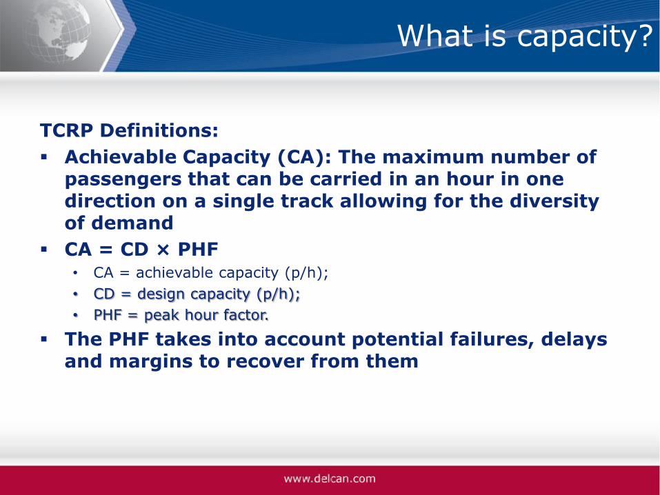
What is capacity?
TCRP Definitions:
Design Capacity (CD): The maximum number of passengers past a single point in an hour, in one direction on a single track.
CD = CL×CT • CD = design capacity (p/h);
• CL = line capacity (trains/h); and
• CT = train capacity (p/train).
The line capacity is a function of the minimum train separation and the dwell time in stations (influenced by signaling / train control)
What is capacity?
TCRP Definitions:
Achievable Capacity (CA): The maximum number of passengers that can be carried in an hour in one direction on a single track allowing for the diversity of demand
CA = CD × PHF • CA = achievable capacity (p/h);
• CD = design capacity (p/h);
• PHF = peak hour factor.
The PHF takes into account potential failures, delays and margins to recover from them

What is capacity?
Line Capacity:
Can be measured as “throughput”: number of Trains Per Hour (TPH)
Dimensioned by the safe braking distance of a train to stop safely before an obstacle: • Rolling Stock performance
• Maximum authorized speed
• Train detection
• Train driver reaction to the change of the signaling status

What is capacity?
Line Capacity improvements:
Worst case: Fixed Block with no cab signal • Safe Braking Distance dimensioned on the worst performing train,
maximum line speed, train driver reaction time.
• Train position anywhere on the track circuit
Improvement: Fixed Block with cab-signal ATP • Safe Braking Distance reduced by taking into account actual train
speed and shorter train driver reaction time.
Optimum: Moving Block with positive train detection • Safe Braking Distance reduced by positive train detection (more
precise), actual train performance and even shorter or no train driver reaction time (ATO)

Re-signaling trends in Europe for urban rail networks
Context:
Urban rail networks in large European cities are becoming complex
Mix of commuter (branches) / metro (core section) types operation
Interface with main line networks
Different stakeholders involved
Have to cope with significant passenger traffic increase coupled with legacy systems obsolescence
7

Re-signaling trends in Europe for urban networks
Main issues to be resolved: • Improve performance: capacity, punctuality and
reliability • Reduce life cycle cost (especially maintenance) • Enhance flexibility of operation • Interoperability (main line business)
Technical solution: • Radio based train control systems: CBTC or ERTMS
Implementation challenges: • Acquisition and development cost • Perceived risk is somewhat medium-high • Interfaces with legacy signaling systems • New or modified rules of operations (organization
readiness)
8

CBTC and ERTMS comparison
CBTC and ERTMS: two different origins
• CBTC was developed specifically for metro / high capacity systems
• ERTMS was developed for main lines to address railway interoperability requirements mandated by the EU
Similar architectures
9
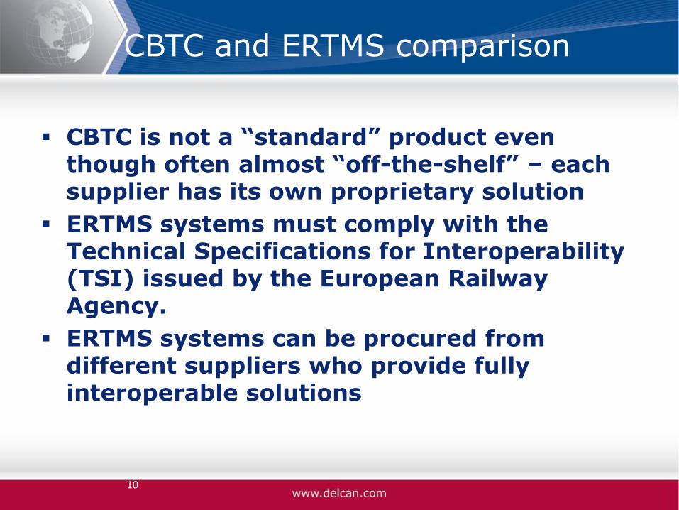
CBTC and ERTMS comparison
CBTC is not a “standard” product even though often almost “off-the-shelf” – each supplier has its own proprietary solution
ERTMS systems must comply with the Technical Specifications for Interoperability (TSI) issued by the European Railway Agency.
ERTMS systems can be procured from different suppliers who provide fully interoperable solutions
10
CBTC and ERTMS comparison
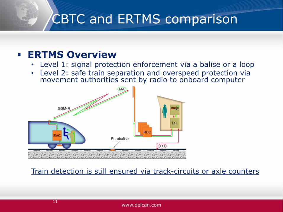
ERTMS Overview • Level 1: signal protection enforcement via a balise or a loop • Level 2: safe train separation and overspeed protection via
movement authorities sent by radio to onboard computer
Train detection is still ensured via track-circuits or axle counters
11

CBTC and ERTMS comparison
ERTMS Overview • Level 3: is similar to ERTMS level 2 except that the train
detection function does not rely on track circuits but on the position calculated by the onboard equipment
• Still under development (alternative version ERTMS Regional for low density lines)
12

CBTC and ERTMS comparison
CBTC Overview
13

CBTC and ERTMS comparison
14
Characteristics CBTC ERTMS Level 2
Architecture Wayside, Onboard, radio communication, fixed transmission network and traffic control center (ATS)
Wayside, Onboard, radio communication, fixed transmission network
Train Detection Train based Track based
Radio Proprietary or standard usually operating around 2.4 or 5.8 GHz
Standard: GSM-R
Level of Automation High: ATO, UTO (driverless) Manual
Headway / Capacity High: 30 TPH and higher Limited due to track based detection and GSM-R performance (up to 22-24 TPH)
Safety level High: vital safe trains separation, continuous overspeed protection
High: vital safe trains separation, continuous overspeed protection
Interoperability None Fully interoperable

CBTC and ERTMS comparison
15
Characteristics CBTC ERTMS Level 2
RAM High level High level
Traffic regulation functions (ATS)
Advanced set of functionalities, included in the products.
Not included in the standard. Each application must interface with an existing TMS or develop its own
Maturity of products
High (100+ applications) High (>6,000 Km and 7000 Locos)

Case Studies
4 locations: similar issues, different solutions:
• London: Crossrail and Thameslink
• Paris: EOLE (Western extension of RER Line E)
• Madrid: Suburban network
• Denmark “Signalling Programme”
16

Case Studies: London
Two concurrent projects: Crossrail (East-West) and Thameslink (North-South) with same capacity requirements in the core sections: 24 TPH
17
Case Studies: London
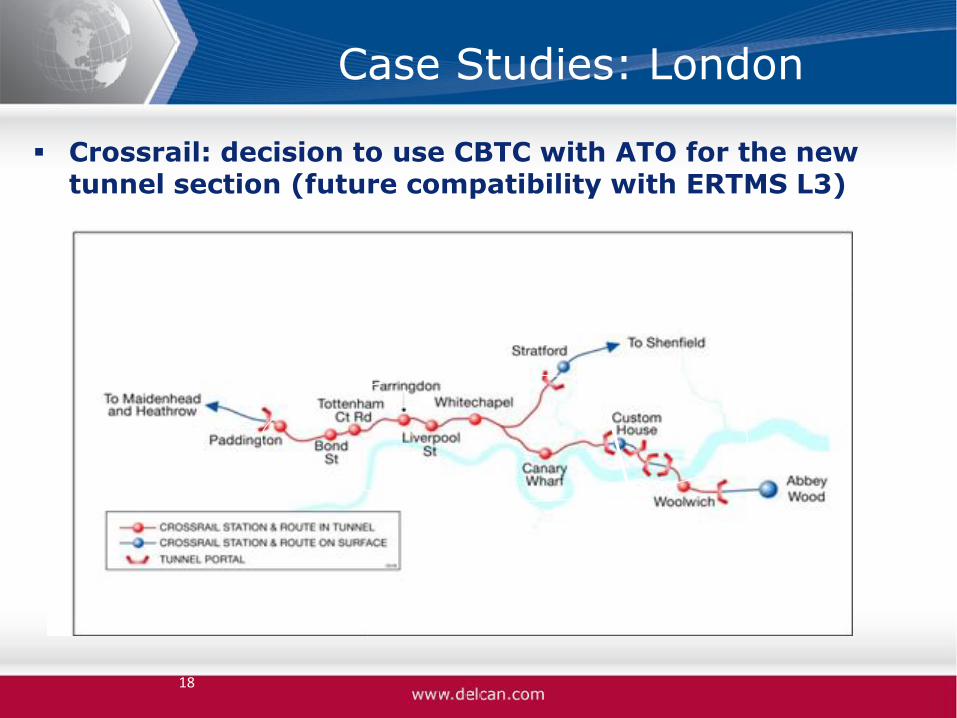
Crossrail: decision to use CBTC with ATO for the new tunnel section (future compatibility with ERTMS L3)
18
New tunnel delivered and operated by TfL (CBTC)
Existing track owned by Network Rail (national mainline)
Existing track owned by Network Rail (national mainline)

Case Studies: London
Thameslink Network Rail
Infrastructure (main line): Decision to install ERTMS Level 2 With Automatic Train Operation (ATO) in Core section
Consistent with UK national strategy for ERTMS rollout
19
Core section
Thameslink and Crossrail comparison
20
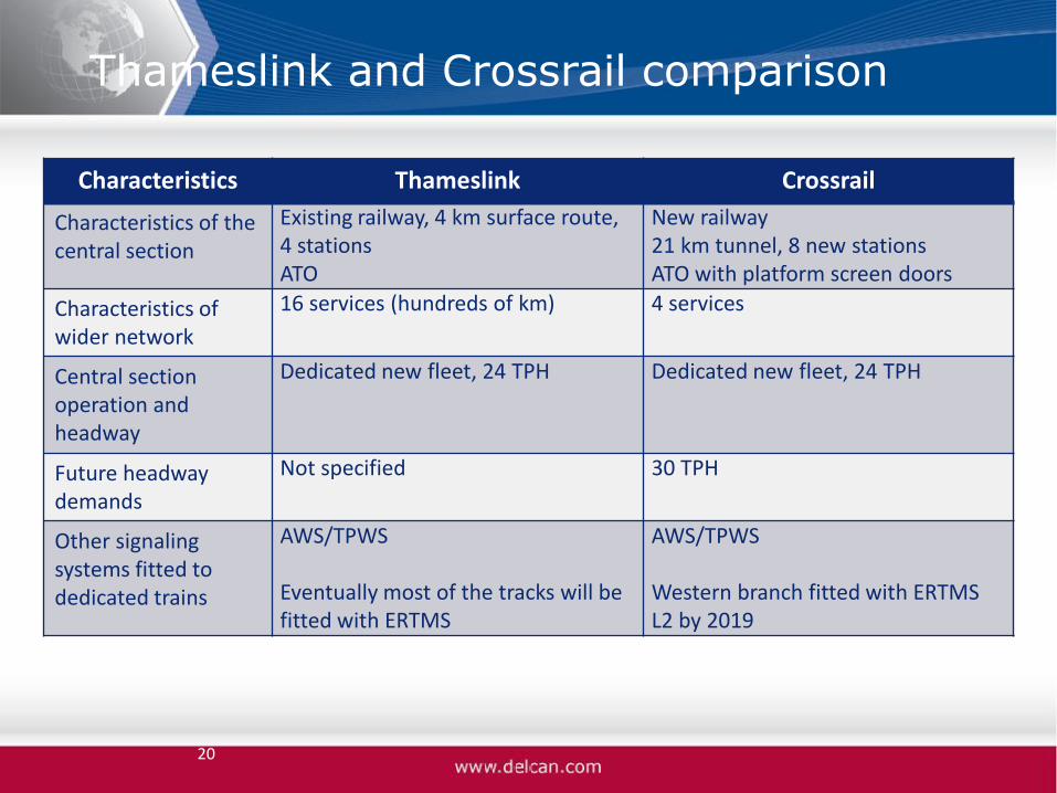
Characteristics Thameslink Crossrail
Characteristics of the central section
Existing railway, 4 km surface route, 4 stations ATO
New railway 21 km tunnel, 8 new stations ATO with platform screen doors
Characteristics of wider network
16 services (hundreds of km) 4 services
Central section operation and headway
Dedicated new fleet, 24 TPH Dedicated new fleet, 24 TPH
Future headway demands
Not specified 30 TPH
Other signaling systems fitted to dedicated trains
AWS/TPWS Eventually most of the tracks will be fitted with ERTMS
AWS/TPWS Western branch fitted with ERTMS L2 by 2019
Case Studies: Paris EOLE Project
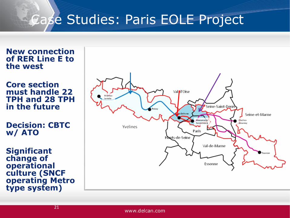
New connection of RER Line E to the west Core section must handle 22 TPH and 28 TPH in the future Decision: CBTC w/ ATO Significant change of operational culture (SNCF operating Metro type system)
21
Western extension: 47 Km of tracks to be upgraded
New tunnel
Existing line

Case Studies: Madrid Suburban Network
Charmin to Atocha high capacity tunnel ERTMS Level 2 installed to achieve 24 TPH in the future (17 TPH actual) All other sections equipped with ERTMS Level 1 with Level 2 upgrade planned (overall national plan to rollout ERTMS)
22

Denmark “Signalling Programme”
Total replacement of all the signaling systems country-wide
3.2 billion Euros funded program, approved by the Danish Parliament in 2009
ERTMS Level 2 rollout for the main lines (Fjernbane): 2020
CBTC rollout for the Copenhagen heavy rail network (S-bane, 7 lines, 200 Km): 2018

Denmark “Signalling Programme”
Main objectives of the “Signalling Programme”:
• Improve punctuality and reliability of the lines (too many signaling equipment failures)
• Address obsolescence issues
• Reduce the maintenance cost for the infrastructure by at least 25% annually
• Implement new signaling with inherent capability to cope with increased capacity in the future
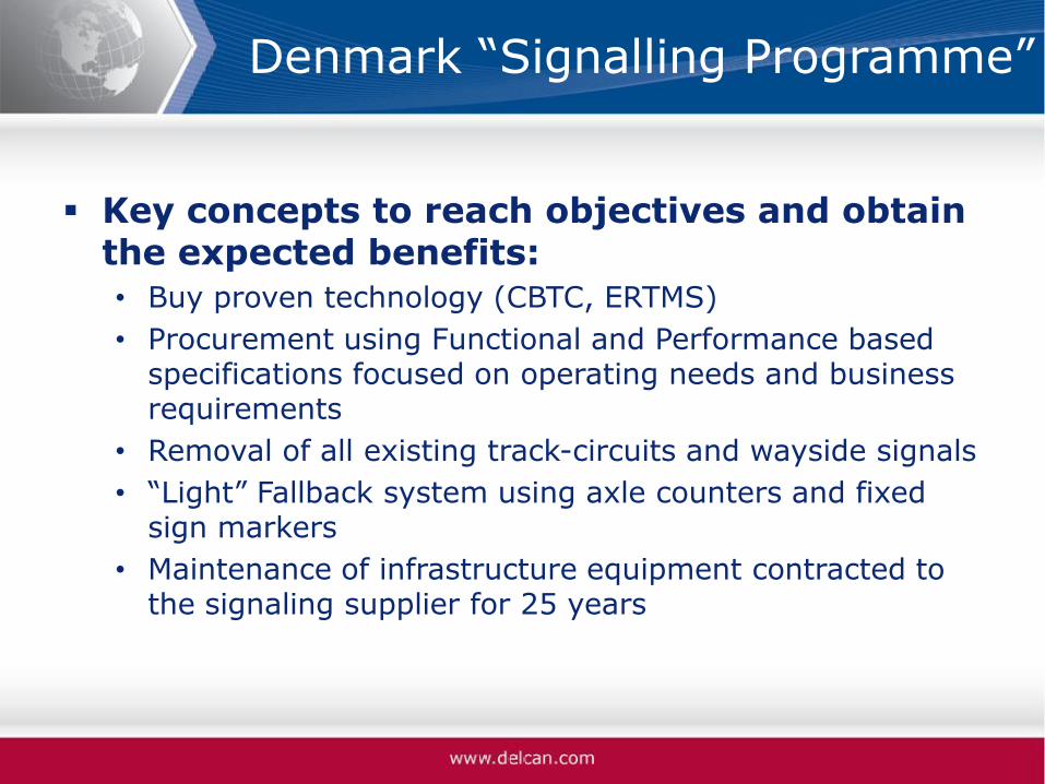
Denmark “Signalling Programme”
Key concepts to reach objectives and obtain the expected benefits:
• Buy proven technology (CBTC, ERTMS)
• Procurement using Functional and Performance based specifications focused on operating needs and business requirements
• Removal of all existing track-circuits and wayside signals
• “Light” Fallback system using axle counters and fixed sign markers
• Maintenance of infrastructure equipment contracted to the signaling supplier for 25 years

PTC Comparison - Context
Context of PTC implementation is different:
• Increase safety
• Mandated by Law (so is ERTMS)
• Significant pressure on the Railroads and Suppliers to meet deadlines
• No time to take a “system approach”
In this context it is difficult to talk about a business case…
26

PTC Comparison – Main Requirements
All PTC systems must be interoperable (on an infrastructure shared by different railroads)
The PTC system functionalities must prevent: • Train-to-train collisions • Over-speed derailments • Incursions into established work zone limits • Movement of a train through an improperly aligned
wayside switch
=> In theory these requirements could be fulfilled by CBTC or ERTMS
27

PTC Comparison – Typical Architecture
28
From the FRA Report on PTC implementation issues (August 2012):
I-ETMS ITCS
ACSES

PTC Comparison – Typical Architecture
Back-office or central level equipment for the dispatching functions
Wayside computers
Onboard equipment
Data communication: the current radio technology use the 220 MHz spectrum (lower bandwidth compared to CBTC or even ERTMS GSM-R)
GPS technology (I-ETMS) or transponders (ACSES) for the positioning function
Implemented as an overlay to the existing signaling system (doesn’t resolve the capacity issue)
29

PTC Comparison – Main systems overview
ACSES: Amtrak for the North-East Corridor (fulfills PTC requirements when combined with existing ATC cab-signal system)
ACSES-2: Evolution of ACSES for the NEC
ITCS: Amtrak Chicago-Detroit
ETMS/I-ETMS: Class I Railroads solution
30

PTC / CBTC / ERTMS fundamental differences
PTC solutions development has been led by freight and passengers railroads with the suppliers support
CBTC solutions development has been led by the suppliers to address transit operators needs
ERTMS has been developed in full collaboration by railways and suppliers
31

PTC / CBTC / ERTMS fundamental differences
Overlay (PTC) versus standalone train control system (CBTC/ERTMS)
Radio link (CBTC requires more data to be transmitted quicker)
Positioning system (CBTC requires higher accuracy due to automatic driving and short headway demands)
32

ERTMS Regional: similar needs than PTC?
ERTMS Regional is an adaptation of ERTMS (wayside and centralized levels)
Low cost solution for low density line with limited signaling protection (“Dark Territory”)
Developed in collaboration with UIC / Swedish Transport Authority
First commercial application in Sweden since February 2012 (Västerdal pilot line – 143 Km)

ERTMS Regional: architecture
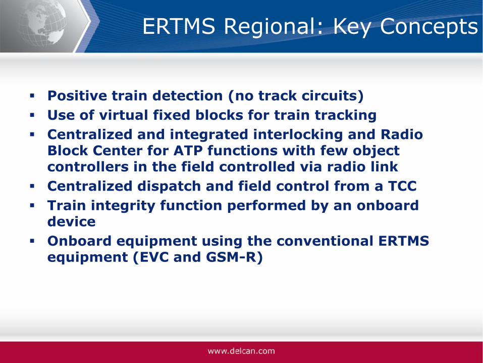
ERTMS Regional: Key Concepts
Positive train detection (no track circuits)
Use of virtual fixed blocks for train tracking
Centralized and integrated interlocking and Radio Block Center for ATP functions with few object controllers in the field controlled via radio link
Centralized dispatch and field control from a TCC
Train integrity function performed by an onboard device
Onboard equipment using the conventional ERTMS equipment (EVC and GSM-R)
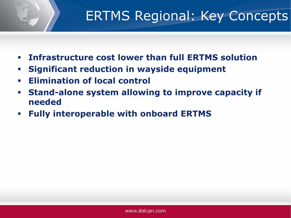
ERTMS Regional: Key Concepts
Infrastructure cost lower than full ERTMS solution
Significant reduction in wayside equipment
Elimination of local control
Stand-alone system allowing to improve capacity if needed
Fully interoperable with onboard ERTMS

Conclusions and Lessons Learned
CBTC remain the first choice for capacity requirements higher than 24 TPH and for metro type applications
ERTMS with ATO can compete with CBTC for certain applications (convergence?)
Choice of signaling goes beyond the capacity issue:
• Life Cycle Cost reduction
• Obsolescence
• Other performance requirements: punctuality and reliability
• Interoperability
37

Conclusions and Lessons Learned
System approach for PTC (post-2015):
• Define common high level set of functional requirements
• Focus on the business and operational requirements: let the supplier design the solutions
• PTC is focused on safety, but what about capacity, operations enhancement, automation, high speed?
• Define a standalone system (not as an overlay)
38

THANKS!
39