Tracerco Diagnostics Bro... · All processes are different so ... very short line lengths and...
19
Tracerco Diagnostics ™ Services for the Refining and Petrochemical Industries
Transcript of Tracerco Diagnostics Bro... · All processes are different so ... very short line lengths and...

Tracerco Diagnostics™
Services for the Refining and Petrochemical Industries
FrothView™
PackView™
LeakTesting
ReactorDistributionStudies
Flare Line
Studies
FCCStudies
Providing real time measurement technologies to assist with critical decision making.

1
Contents
TRU-SCAN® 2
Tru-Grid™ Scan 3
ThruVision™ Scan 4
Tru-Pipe™ Scan 5
Tru-Neutron™ Scan 6
Tracerco Diagnostics™ Flow study 7
Tracerco Diagnostics™ Residence study 10
Tracerco Diagnostics™ Distribution study 11
Tracerco Diagnostics™ Leak study 12
Tracerco Diagnostics™ FCCU study 14
The Profiler™ 15
Tracerco™ Instruments 16
FrothView™
PackView™
LeakTesting
ReactorDistributionStudies
Flare Line
Studies
FCCStudies

2
Tracerco Scanning Services TRU-SCAN® Application
TRU-SCAN® features identified:
• Verify placement of trays.
• FrothView™ evaluation of tray froth heights.
• Determine presence and extent of foaming and fouling.
• Detect tray damage and flooding.
• Detect mechanical, rate or process related problems.
Do you have problems with the operation of your stripper/absorber or fractionation tower?
Is this limiting production?
Do you want to reduce your operating costs?
Do you want to reduce your shutdown time?
Tracerco’s TRU-SCAN® technology, utilizing FrothView™, is used to evaluate the mechanical integrity and hydraulic performance of trayed columns by measuring the total or true froth height on tray decks and liquid backup in downcomers. Damaged or missing trays, plugged downcomers, feed issues, and tray fouling are examples of problems with columns that can be diagnosed with a TRU-SCAN®.
Tracerco scanning services have a proven track record with over 40 years of experience in assisting with plant start-ups, pre-shutdown planning and operational trouble-shooting. A TRU-SCAN® is generally performed without any preparation to the tower i.e. no insulation is removed. Tracerco’s TRU-SCAN® service has proven to be cost effective by reducing off-spec production and equipment downtime. In today’s highly competitive refining, petrochemical, and chemical processing markets, more customers are using TRU-SCAN® information to determine plant bottlenecks and optimize performance.
Tracerco TRU-SCAN® technology provides a new methodology, FrothView™, that has been developed and tested allowing the total froth height on each tray to be measured using new detector technology and software interpretation.

32
Tracerco Scanning Services Tru-Grid™ Scan Applications
Tru-Grid™ Scan features identified:
• Verify placement of packed beds, distributors and collectors.
• PackView™ evaluation of the quality of liquid phase distribution.
• Detect problems such as fouled or crushed packing, overflowing distributors and collector trays, as well as flooding or foaming.
A Tru-Grid™ Scan is one of the most common and cost effective methods of identifying liquid maldistribution and other problems affecting packed column performance. A Tracerco Tru-Grid™ Scan is a series of four conventional column scans performed using a grid consisting of pairs of parallel scanlines orientated ninety degrees to each other.
The objective of the Tru-Grid™ Scan is to measure the degree of bias (or coincidence) among the four scans under identical scan conditions. A Tru-Grid™ Scan of a bed that has uniform liquid distribution throughout will show little variation (implying little density difference) from one scan to another with all four scanlines overlaying one another. Non-uniformity among the scans implies density differences which can normally be attributed to an imbalance in liquid traffic.
A Tru-Grid™ Scan can also show discrepancies in liquid level on orifice-type distributors, liquid overflowing vapor risers on chimney trays and distributors. Tru-Grid™ Scans can also detect evidence of problems such as fouling and crushed or corroded packing which often results in distribution problems.
MALDISTRIBUTIONScales: 100 - 10000
North ScanlineSouth Scanline
East ScanlineWest Scanline
Clear Vapor Bar
COLLECTOR
DISTRIBUTOR
100 1000
20
20
20
20
20
10000
36
3840
42
44
46
48
50
52
54
56
14
1618
20
22
24
26
28
30
32
34
58
60
62
64
66
68
70
COLLECTOR – DRAW TRAY
DISTRIBUTOR
RING DRY
DENS
ITY
(5 lb
/ft3 )
RING
DISTRIBUTOR
BED 1BED 1
BED 3BED 3
BED 2BED 2
Tracercohttp://www.tracerco.com
��/�t�
��/�t�
��/�t�
��/�t�
��/�t�
��/�t�
10 5
10 5
10 55
10 5
10 5
20 10 5
10 5
10
10
10 5
20 10 5
PackView™ analysis, a new method using enhanced detection and analysis software, displays a secondary density scale or packing retention scale through beds of packing. The retention scale shows the reference density for the dry packing. Additional measured density would typically be from liquid flow (retention) through the packing.
4
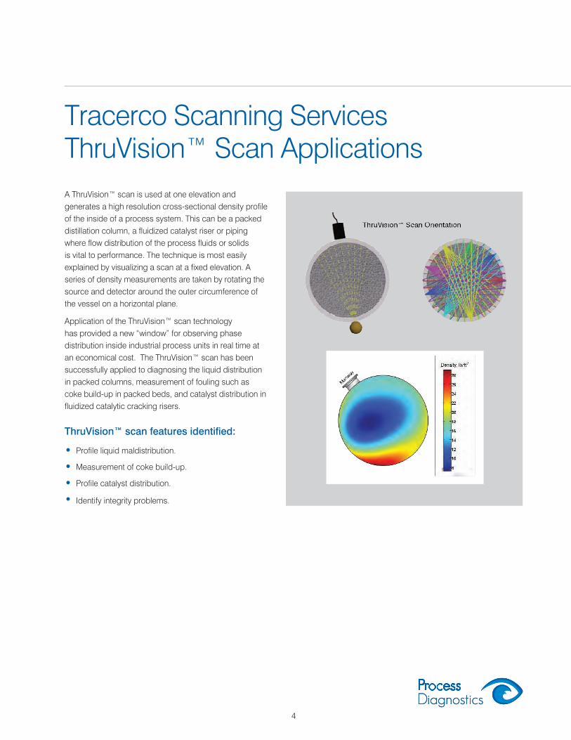
Tracerco Scanning Services ThruVision™ Scan Applications
ThruVision™ scan features identified:
• Profile liquid maldistribution.
• Measurement of coke build-up.
• Profile catalyst distribution.
• Identify integrity problems.
A ThruVision™ scan is used at one elevation and generates a high resolution cross-sectional density profile of the inside of a process system. This can be a packed distillation column, a fluidized catalyst riser or piping where flow distribution of the process fluids or solids is vital to performance. The technique is most easily explained by visualizing a scan at a fixed elevation. A series of density measurements are taken by rotating the source and detector around the outer circumference of the vessel on a horizontal plane.
Application of the ThruVision™ scan technology has provided a new “window” for observing phase distribution inside industrial process units in real time at an economical cost. The ThruVision™ scan has been successfully applied to diagnosing the liquid distribution in packed columns, measurement of fouling such as coke build-up in packed beds, and catalyst distribution in fluidized catalytic cracking risers.

5
Tracerco Scanning ServicesTru-Pipe™Scan
Tracerco’s Tru-Pipe™ Scan technology offers solutions to a variety of process problems by:
• Measuring the presence, extent and position of solids within a process pipe, especially flare lines.
• Identify slugging flow.
• Confirm carry over or carry under from a process vessel.
The use of Tru-Pipe™ Scan technology offers a non-invasive method to examine the contents of a pipe in a wide range of process industries. A measurement is taken of signal intensity and a direct interpretation of pipeline contents is made. The most common applications of this technique include the determination of solids build-up within a pipe, slugging of process gas, liquid or solid over a period of time through a transfer pipeline and the confirmation of liquid carry over or gas carry under.
The Tru-Pipe™ Scan technique is used on process equipment to determine the location and depth of solid deposits.
Tru-Pipe™ Scan Orientation
Vertical radiation count = Y Horizontal radiation count = X
Difference between X and Y allows thickness of deposit to be calculated

6
Tracerco Scanning ServicesTru-Neutron™ Scan
Do you have problems knowing your tank inventory?
Are liquid interfaces where your instruments say they are?
Are blockages restricting process flows?
Routine scans of tanks and spheres can determine sludge and product levels and if there are any plugging issues in vent lines. Results from the scans are available onsite, allowing operators optimal time to schedule shutdowns and preparation of the storage facility for startup.
These are only a few examples of the use of this flexible and accurate measurement tool. All processes are different so please seek our advice if you have a problem that appears to be suitable for investigation.
The Tru-Neutron™ Scan technology has a wide range of applications in industrial processes including:
• Level and interface measurement in storage tanks
• Deposit/vapor profile in pipelines
• Foam heights in tower downcomers
• Liquid levels in tower distributors, chimney trays and draw sumps
• Interface/emulsion band in separators
• Levels in reboilers/heat exchangers
These and other process control problems can be addressed using the Tru-Neutron™ Scan technology. This is a non-invasive, rapid, and accurate technique usually performed without any preparation to the vessel. Results are instantly available allowing any process changes to be made.
Storage Tank Scan

7
Tracerco Diagnostics™ Flow Study
Typical systems that can be measured include:
The measurement of flow within a process is often required where no metering is present, e.g. such as to measure flow distribution between main headers and branch headers, or to verify existing flow measurement devices. The use of the Tracerco Diagnostics™ Flow study technology offers a rapid, accurate and cost effective method of determining flows of solids, gases and liquids. The results from such measurements can play a key role in predictive maintenance, process optimization and reduced downtime.
Tracerco engineers will study the process system to deter-mine the most suitable injection point and detector layout to gain optimum information about the process. Consideration will then be given to the choice of tracer to ensure process compatibility and the required concentration. The tracer material is then injected into the process stream via the identified point. Measurement of the injected pulse through the system is made using external detectors or sampling with no affect on process operations.
Would you like to be able to determine flow rate through flare lines and piping systems?
Are you experiencing off-spec product from your feed/effluent exchangers?
Do you suspect maldistribution or poor mixing characteristics is affecting your reactor efficiency?
The following Tracerco service applications are applied to the investigation of industrial processes to allow plant engineering and operations staff quickly troubleshoot, optimize or resolve operational issues. Better knowledge about a problem will reduce the cost of making corrections and reduce downtime.
Tracerco Diagnostics™ online investigations use radioisotope and chemical tracers to identify leaking heat exchangers, measure the distribution of feed into catalyst beds, establish mixing characteristics in reactors and conduct flare flow studies to measure and locate sources of emissions.
• Flare line systems • Cooling water towers and systems
• Relief valves • Compressors and turbines
• Effluent streams • Process material systems for mass balances
8
Tracerco Diagnostics™Flow Study
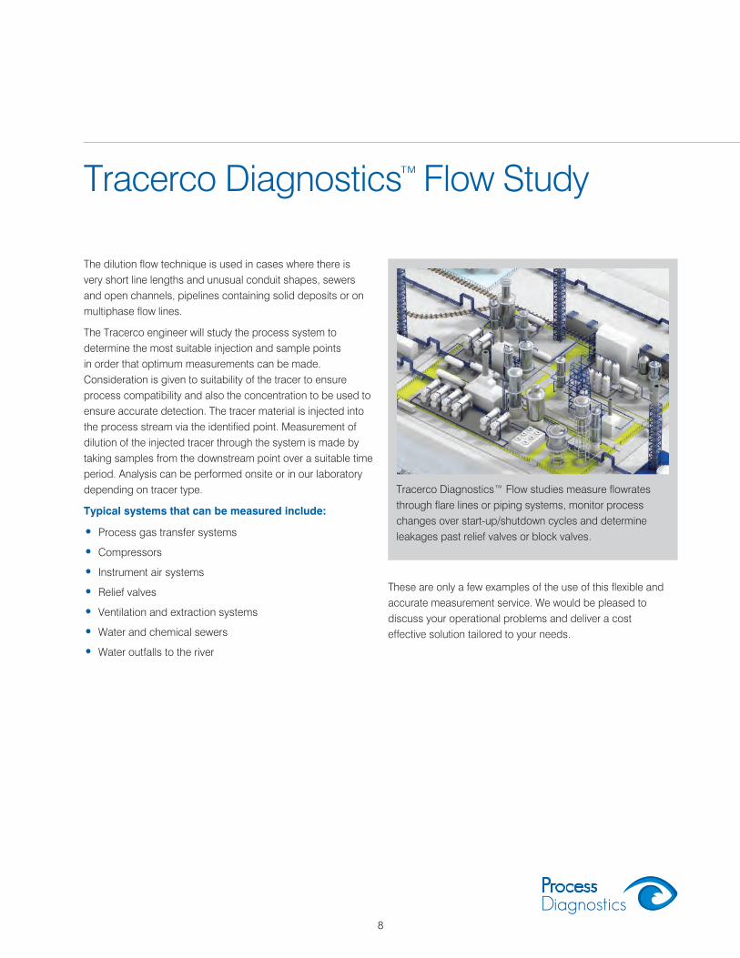
The dilution flow technique is used in cases where there is very short line lengths and unusual conduit shapes, sewers and open channels, pipelines containing solid deposits or on multiphase flow lines.
The Tracerco engineer will study the process system to determine the most suitable injection and sample points in order that optimum measurements can be made. Consideration is given to suitability of the tracer to ensure process compatibility and also the concentration to be used to ensure accurate detection. The tracer material is injected into the process stream via the identified point. Measurement of dilution of the injected tracer through the system is made by taking samples from the downstream point over a suitable time period. Analysis can be performed onsite or in our laboratory depending on tracer type.
Typical systems that can be measured include:
• Process gas transfer systems
• Compressors
• Instrument air systems
• Relief valves
• Ventilation and extraction systems
• Water and chemical sewers
• Water outfalls to the river
Tracerco Diagnostics™ Flow studies measure flowrates through flare lines or piping systems, monitor process changes over start-up/shutdown cycles and determine leakages past relief valves or block valves.
These are only a few examples of the use of this flexible and accurate measurement service. We would be pleased to discuss your operational problems and deliver a cost effective solution tailored to your needs.
9
Pulse Velocity and Dilution Technique
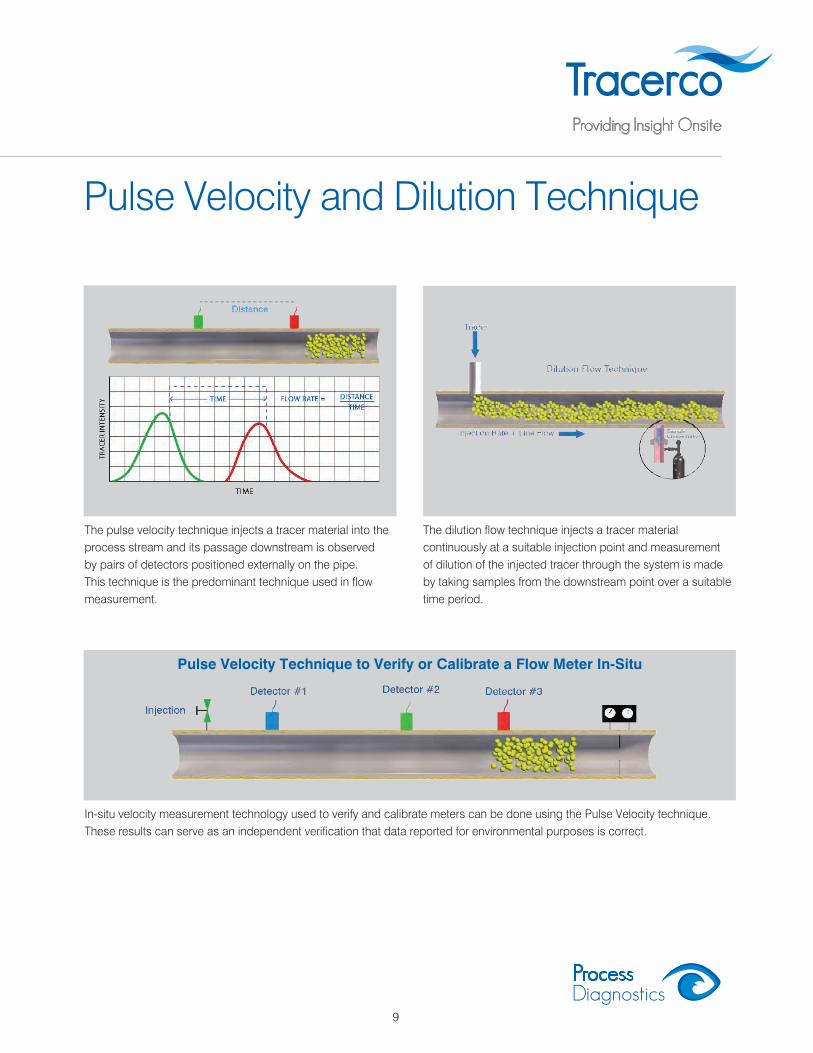
In-situ velocity measurement technology used to verify and calibrate meters can be done using the Pulse Velocity technique. These results can serve as an independent verification that data reported for environmental purposes is correct.
The pulse velocity technique injects a tracer material into theprocess stream and its passage downstream is observed by pairs of detectors positioned externally on the pipe. This technique is the predominant technique used in flow measurement.
The dilution flow technique injects a tracer material continuously at a suitable injection point and measurement of dilution of the injected tracer through the system is made by taking samples from the downstream point over a suitable time period.
Pulse Velocity Technique to Verify or Calibrate a Flow Meter In-Situ

10
Tracerco Diagnostics™Residence Study
The residence time and distribution of material through mixing, reaction or separation vessels can be critical to industrial process efficiency. A Tracerco Diagnostics™ Residence study can offer a rapid, on-line, cost effective method of determining these process parameters. A tracer is injected into the inlet of a vessel and its exit is measured using an external detector or by taking samples. The residence time measurement of vapor or liquid passage through a vessel is used to determine the degree of mixing or whether plug flow occurs. Test results can indicate vapor or liquid by-passing and determine build-up of fouling material in the vessel. The Tracerco Diagnostics™ Residence study can be used to accurately diagnose integrity problems with internals that can assist plant personnel in
identifying problematic operations and make modifications to increase efficiency.
Tracerco Diagnostics™ Residence and Distribution Studies can be used to measure a number of operational parameters on the following equipment:
• Reactors
• Oil/Water Separators
• Packed Bed Distillation Towers
• Driers
• FCCU Systems
A Tracerco Diagnostics™ Residence study can offer a rapid, online, cost effective method to determine the transit time of material through mixing, reaction or separation vessels that can be critical to industrial processes.
11
Tracerco Diagnostics™Distribution Study
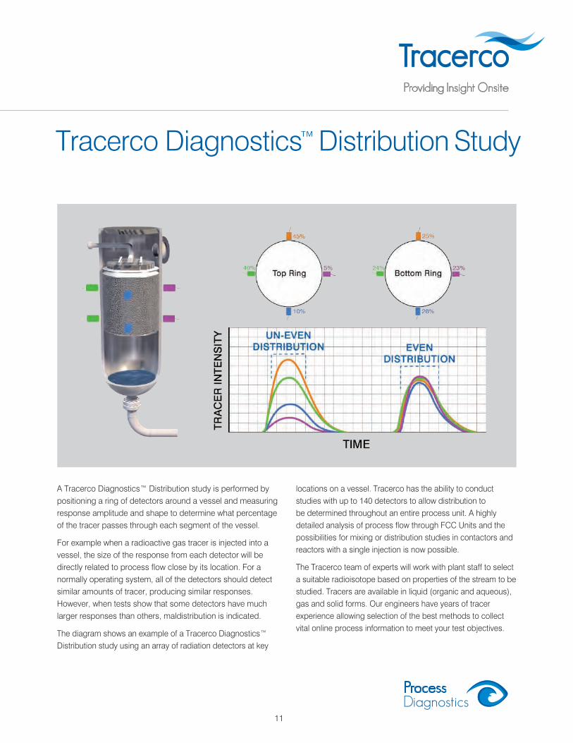
A Tracerco Diagnostics™ Distribution study is performed by positioning a ring of detectors around a vessel and measuring response amplitude and shape to determine what percentage of the tracer passes through each segment of the vessel.
For example when a radioactive gas tracer is injected into a vessel, the size of the response from each detector will be directly related to process flow close by its location. For a normally operating system, all of the detectors should detect similar amounts of tracer, producing similar responses. However, when tests show that some detectors have much larger responses than others, maldistribution is indicated.
The diagram shows an example of a Tracerco Diagnostics™ Distribution study using an array of radiation detectors at key
locations on a vessel. Tracerco has the ability to conduct studies with up to 140 detectors to allow distribution to be determined throughout an entire process unit. A highly detailed analysis of process flow through FCC Units and the possibilities for mixing or distribution studies in contactors and reactors with a single injection is now possible.
The Tracerco team of experts will work with plant staff to select a suitable radioisotope based on properties of the stream to be studied. Tracers are available in liquid (organic and aqueous), gas and solid forms. Our engineers have years of tracer experience allowing selection of the best methods to collect vital online process information to meet your test objectives.

12
Tracerco Diagnostics™ Leak Study
Leaks in a heat exchanger usually result in off-specification material being produced. If the system has a “bank” or group of exchangers then it is very difficult to identify which one(s) is leaking using laboratory sample analysis alone.
The use of tracer materials offers a rapid and unambiguous online method for detecting leaks within heat exchangers, reactors and flowline valves. This can greatly reduce plant down time and yield savings in maintenance costs.
The site requirements include a suitable injection point on the primary inlet line into which the pulse of appropriate tracer can be injected. If samples are to be taken, a process must have a suitable point downstream of the suspect vessel(s) from which samples can be taken.
A Tracerco Diagnostics™ Leak study has a wide range of applications as an aid to process diagnostics and inspection.
These include:
• Reboiler/condenser leaks in distillation towers
• Leaks on banks of heat exchangers
• Leaks through bypass valves
• Vent and relief valve leakage
• Compressor “Ring” leakage
• Ammonia syn gas loop and converter leakage
Tracerco Diagnostics™ Leak studies detect the presence of a heat exchanger leak online no matter how small. Not only can the leak be narrowed down to a specific heat exchanger but the study can be performed without the need for a shutdown.
To address the need to find very small leaks, Tracerco carried out an extensive research and development program looking at the application of specialist chemical tracers. The chemical tracer approach can provide plant personnel new alternatives for investigating plant operating performance with the goal of reduced diagnostic and shutdown time.

13
Heat Exchanger Leakage
Helium leak study applications for exchanger and vacuum systems
Two methods are employed to determine leakage, the sampling technique and the external detection technique. The first requires a sample point on the downstream line of the secondary stream from which to draw material over a short time period. The samples collected are delivered to a local Tracerco laboratory where they are analyzed for tracer content.
The second method uses external detectors mounted on the lines to monitor the passage of the injected tracer. Any leakage would be indicated as a “peak” on the detector mounted on the secondary stream exit line.
For example a client believed there was a leak in one of the two feed/effluent exchangers in a hydrotreating unit and wanted to determine which exchanger was leaking.
Using the external detection technique the blue detector response indicated tracer flow proving that exchanger B was leaking. The main portion of radiotracer through the feed side of the B exchanger is shown by the red (inlet) and green (outlet) detector response curves. A comparison of areas under the red, green and blue plot results indicated that a 2.5% leak was detected.
The client was pleased to hear that the source of the high sulfur level was a leaking exchanger and to know which exchanger to repair. They took a short outage to repair the leak. When they restarted the plant, the sulfur levels returned to normal.
Tracerco offers offline testing of exchanger tubes and online testing of vacuum systems using our helium leak study application. For vacuum systems, locations of air ingress can be identified. Offline investigations of exchangers identify each leaking tube so it can be repaired or plugged. For additional information on our helium leak study applications please contact a technical advisor in your area.

14
Tracerco Diagnostics™ FCCU Study
Reactor
Cyclone Operation and Distribution Study
Catalyst Bed Level Measurement
Efficiency of Riser Termination Device
Residence Time
Spent Catalyst & Regenerated Catalyst Standpipes
Catalyst Slugging Study
Catalyst Density Profile
Regenerator
Cyclone Operation
Cyclone Distribution Study
Catalyst Bed Level Measurement and Extent of Bed Dilute - Phase
Catalyst and Air Distribution Study
Residence Time
Stripping Section
Density Profile
Catalyst and Vapor Flow Distribution & Residence Time
Reactor Riser
Riser Density Profile
Catalyst and Vapor Distribution
Catalyst and Vapor Velocities (Slip Ratio)
The Fluidized Catalytic Cracking Unit (FCCU) is the economic heart of today’s refinery. Small increases in yield can bring significant gains in productivity and revenues. Tracerco Diagnostics™ FCCU studies have diagnosed operating problems and helped improve the performance of all major components of FCC units.
Each project is customized to provide the information needed to optimize or troubleshoot your specific process. All testing is performed while the unit is online and will not interfere with normal unit operations or production scheduling. Data collected can be used to identify operating parameter changes to improve unit productivity, or gauge the accuracy of process modeling and simulation. Tracerco’s experience involves numerous studies performed on units worldwide allowing a better understanding of the integrated processing components of today’s FCCU’s.
A Tracerco Diagnostics™ FCCU study utilizes our diagnostic capabilities with both sealed source and tracer technologies. These are used to measure density profiles within vessels as well as the velocity, distribution and residence time of the catalyst or vapor phase through any part of the system. This includes testing to determine the efficiency of riser termination devices, cyclones or distribution devices.
A typical study may employ upwards of 50 detectors, inspecting almost the entire system from a common injection point. The tagged process stream can be followed completely through either the reactor vessel or the regenerator.
For example, tracer material injected into the riser can provide:
• Catalyst and vapor traffic velocities and slip through the riser
• Determination of efficiency of the riser termination device
• Flow distribution through the reactor and stripper
• Cyclone distribution/operating characteristics
• Reactor/stripper residence times
Vapor traffic is usually tagged using an inert gas. The catalyst traffic may be tagged using system native catalyst, E-Cat, catalyst fines, or any specific particle size distribution which has been activated by Tracerco.
For additional information on FCCU services provided by Tracerco please reference our FCCU brochure that can be found on our website at www.tracerco.com or contact an office in your area to request a copy.

15
Tracerco™InstrumentsThe Profiler™
The Profiler™ for Desalters
Typical applications for The Profiler™ include:
• Oil/water/gas separation vessels
• Heavy oil separation vessels
• Vertical cyclonic separators
• Desalters
• Electrostatic coalescers/treaters, degassers
• Multiphase settling tanks
• Inclined plate separators - oil sands
• Primary separation vessels - oil sands
• Froth tanks - oil sands
Benefits of The Profiler™
• Increased production throughput
• Real time process optimization
• Reduce shutdowns and chemical additive costs
• Improves asset environmental compliance
• Low maintenance
Tracerco has developed an award-winning instrument, The Profiler™, that is used to measure the vertical distribution of various materials contained in separation process vessels.
The Profiler™ has now been designed to withstand the elevated operating temperatures typically experienced within a Desalter vessel. The instrument is non contact, has no moving parts and requires minimal maintenance. The vertical measurement of the various phases in the Desalter provides information on the extent of inter-phase mixing that can be monitored to optimize fluid throughput while providing costs saving on chemical additives.
If you would like to learn more about any of the Tracerco™ Instruments contact a technical advisor today for additional information or to schedule an on-site presentation.

16
Tracerco™Instruments
Optimus™
Tracerco™ Phaser
Hyperion™ for Density
Nucleonic gauges that utilize the unique properties of radioisotopes to provide measurement and control are widespread throughout industry.
Tracerco™ Instruments provide a wide range of specialist measurement solutions, measuring key parameters such as level, density and interface.
These instruments are all non-wetted devices, allowing them to be used in the harshest of process conditions such as high temperatures, slurries or corrosive materials.
Benefits of Tracerco™ Instruments:
• Mechanical failure eliminated
• No fouling issues
• Easy to retrofit
• Greater control
• Reduced maintenance costs
For further details please contact:
North American Headquarters:4106 New West DrivePasadena, TX 77507 USATel: 281 291 7769Fax: 281 291 7709Toll Free: 800 288 8970
Field Office Locations:Corpus Christi, TX 78408 USATel: 361 888 8233
XM0149/0/D
Concord, CA 94520 USATel: 925 687 0900
Paramount, CA 90723 USATel: 562 633 8800
Newark, DE 19702 USATel: 302 454 1109
Merrillville, IN 46410 USATel: 219 945 0400
Baton Rouge, LA 70820 USATel: 225 761 0621
West Valley City, UT 84119 USATel: 801 478 0736
Edmonton, AB, T6E 6A6 CANADATel: 780 469 0055
Calgary, AB, T2Y 2Z7 CANADATel: 403 931 6705
Sarnia, ON, N7S 5G5 CANADATel: 519 332 6160
Rio de Janerio, RJ, Brasil, CEP 22775-044Tel: +55 21 3385 6800
Email: [email protected] Web: www.tracerco.com