Trac - King In-Motion Satellite System Model 9762-LPmanuals.solidsignal.com/King-Dome 9762 Trac-King...
44
Trac-King In-Motion Satellite System Model 9762-LP Installation and Operating Instructions 11200 Hampshire Avenue South, Bloomington, MN 55438-2453 Phone: (800) 982-9920 Fax: (952) 922-8424 www.kingcontrols.com 1355 REV S Satellite Solutions for Mobile Markets Trac-King ®
Transcript of Trac - King In-Motion Satellite System Model 9762-LPmanuals.solidsignal.com/King-Dome 9762 Trac-King...

Trac-King In-Motion Satellite SystemModel 9762-LP
Installation and Operating Instructions
11200 Hampshire Avenue South, Bloomington, MN 55438-2453Phone: (800) 982-9920 Fax: (952) 922-8424
www.kingcontrols.com
1355 REV S
Satellite Solutions for Mobile Markets
Trac-King
®


Page 1
IMPORTANT!The satellite TV market is expanding and changing. The information in this manual was accurate at thetime of printing. If your King-Dome does not operate as outlined in this manual please call King Controlsat (800) 982-9920 or visit our website at www.kingcontrols.com.
This King-Dome will receive available HDTV programming from DIRECTV Ku band satellites at 101°, 110°and 119° with a properly installed HD converter accessory #9747. It will not receive channels broadcastfrom DIRECTV’s Ka band satellites at 99° and 103°.
Please read this entire manual before beginning the installation.
Note: The following upgrade kit is available for this unit:
Upgrade Kit #9747: Enables viewing of HD broadcasts from the DIRECTV 110° satellite.
For more information, call the King Controls Sales Department at (800) 982-9920.
TABLE OF CONTENTS
Section Contents Page
1. INTRODUCTION............................................................................................................2
2. DEFINITION OF TERMS ...............................................................................................3
3. INSTALLATION.........................................................................................................4-16
4. OPERATION ...........................................................................................................18-21
5. AUTOMATIC SATELLITE SWITCHING (DIRECTV®)...................................................22
6. AUTOMATIC SATELLITE SWITCHING (DISH NETWORKTM - EXPRESSVU) .......23-29
7. DIRECTV HDTV CONNECTIONS..........................................................................30-32
8. TROUBLESHOOTING............................................................................................34-38
9. MAINTENANCE...........................................................................................................39
10. LIMITED WARRANTY .................................................................................................40
ELECTRICAL HAZARD WARNING!
The coaxial cable that connects the dome unit to the tuner carries a 24 volt electricalcurrent. Exercise extreme caution when handling this cable. Do not cut, break, or splicethis line. Do not insert or connect any devices such as splitters or any other device for anyreason. This line is not compatible with any other equipment. Damage will occur to anydevice other than the dome unit if connected to the antenna port on the tuner.
DIRECTV® is a registered trademark of DIRECTV, Inc.Dish NetworkTM is an official trademark of Echostar Communications Corporation.Bell ExpressVu is an official trademark of Bell Canada.DVB® is a trademark of the DVB Digital Video Broadcast Project (1991-1996)

Page 2
The Trac-King In-Motion Satellite System includes 4 main components (Fig. 1).
Dome (Antenna) Unit Located on the roof of the vehicle. The dish is covered by aprotective dome that keeps operational components free fromthe elements.
Controller Located in the vehicle. Used to activate and monitor thesystem, and access programming and diagnostic information.
Tuner Located in the vehicle. Decodes the satellite signal so theTrac-King locks onto and tracks the correct satellite.
Power Supply Located in the vehicle. Supplies proper operating voltage tothe Trac-King.
SECTION 1 INTRODUCTION
Note: A TV, satellite receiver, and program subscription are also required for satellite TV viewing.(Purchased separately.)
Fig. 1
Note: For optional second receiver hookup see Pages 14-15.
King-Dome
START/STOP DISPLAYSELECT MODIFY

Page 3
AZIMUTH: Angle in degrees measured clockwise from Magnetic North (0°) (Fig. 2).
SIGNAL STRENGTH: Intensity of electronic signal received from the satellite transmission.
SECTION 2 DEFINITION OF TERMS
Fig. 2
Fig. 3
ELEVATION: Angle in degrees measured from the ground plane (Fig. 3).

Page 4
SECTION 3 INSTALLATIONTOOLS AND MATERIALS REQUIRED:
- drill and drill bit set- tape measure- 7/16” open end wrench (coax connections)- adhesive sealant (compatible with roof material)- appropriate fasteners and tools to install all components and wiring- 5/32” allen wrench, channel lock or pliers (to remove shipping bolts)- wire cutter (to remove shipping tie strap)
KIT CONTENTS:
1. Unpack and identify all components (Fig. 4).
Fig. 4

Page 5
IMPORTANT! The tie strap and spacer, and the bolts and washers must be removed from the bottom ofthe dome unit prior to installation. DO NOT REMOVE THE DOME COVER TO REMOVETHESE SHIPPING RESTRAINTS.
YOU MUST PLUG THE SHIPPING RESTRAINT HOLE AND TWO SHIPPING BOLT HOLESWITH THE SUPPLIED PLUGS. (ATTACHED TO TIE STRAP SHIPPING RESTRAINT.)
2. Remove and discard the tie strap and spacer (KEEP RUBBER PLUGS AND GREASEPACKET), and the (2) bolts and (2) washers that pass through the bottom of the base(Fig. 5).
Fig. 5
IMPORTANT!Remove and discard Bolts and Washers prior to installation.
IMPORTANT!Remove and discard Tie Strap and Plastic
Spacer prior to installation.
KEEP RUBBER PLUGS AND GREASE PACKET.
DO NOT REMOVE DOME COVER

Page 6
IMPORTANT!After removing shipping restraints, firmly insert plugs into appropriate
holes. Plugs should be flush with base.
3. Insert provided plugs into holes that were occupied by tie strap and shipping bolts.Inserted plugs should be flush with base (Fig. 6).
Fig. 6

DOME LOCATION
1. Select an area on the roof for the dome unit and the location where the coax cables willenter the vehicle through the roof to the satellite receivers and internal components. Usethe following criteria:
a) The shortest distance between the dome unit and the main satellite receiver is mostdesirable.
b) The dome unit requires a 28 inch diameter circle.
c) The dome unit should be mounted on the centerline of the vehicle (side to side).
d) There must be no “line of sight” obstructions from this location. Air conditioningunits, other antennas, and storage areas that are too close to the dome unit mayprevent the satellite signal from reaching the dish (Fig. 7).
HEIGHT OFOBSTRUCTION
APPROXIMATE MINIMUM DISTANCE
TO DOME EDGE10” 8”11” 10”12” 12”
13” 14”
14” 16”
15” 18”
16” 20”
Fig.7
2. Place dome unit in selected area.
IMPORTANT! Make sure shipping restraints are removed from bottom of dome unit and plugs inserted inholes (Fig. 5, Page 5 and Fig. 6, Page 6).
Cable connections must ALWAYS be positioned facing rear of vehicle.
Page 7

Page 8
Fig. 9
IMPORTANT! The dome unit MUST be mounted to the air ride cab: NEVER toany structure mounted directly to the frame.
3. The dome unit must be positioned so that both feet on each side of the vehicle are equaldistances from the roof edge. This should be checked by measuring the distance fromeach foot to the roof edge. Confirm that these measurements are equal (Fig. 8).
Example of truck installation using bracket.See bracket instructions for proper installation.
IMPORTANT! For installations on trucks with air shields, a bracket must be used for mounting the domeunit. The dome unit MUST be mounted to the air ride cab: NEVER to any structuremounted directly to the frame.
See bracket instructions for proper installation (Fig. 9).
IMPORTANT! The dome should never be mounted so that it is tilted more than twodegrees in any direction.
Fig. 8
IMPORTANT!Cable connections must
always face REAR ofvehicle.

Page 9
COMPONENT LOCATION
1. Determine the location of the internal components using the following criteria:
a) The Controller, Tuner, and Power Supply should be in the same general vicinity ofthe main satellite receiver, and ACCESSIBLE FOR OPERATION ANDMAINTENANCE PURPOSES.
b) The Tuner should not be stacked directly on top of other electronics. If located in acabinet or other enclosure, make sure there is adequate ventilation around the unit.
c) The Controller should be conveniently located for the end user. (If using the WallMount Faceplate, see page 16.)
d) All components should be secured so they do not shift or bounce around duringvehicle motion.
2. Place the components in the selected areas.
ELECTRICAL HAZARD WARNING!
The coaxial cable that connects the dome unit to the tuner carries a 24 volt electricalcurrent. Exercise extreme caution when handling this cable. Do not cut, break, or splicethis line. Do not insert or connect any devices such as splitters or any other device for anyreason. This line is not compatible with any other equipment. Damage will occur to anydevice other than the dome unit if connected to the antenna port on the tuner.
To verify proper operation of the components in their selected locations, perform a SystemLocation Check as follows:
1. TEMPORARILY connect system as shown on pages 14 and 15.
2. Verify system operates properly as described in Section 4 OPERATION, Page 18.
3. After verifying system operates properly, disconnect all components.
SYSTEM LOCATION CHECK
Page 10
DOME INSTALLATION AND EXTERNAL WIRING
Fig. 10
Note: The installer is responsible for determining the most appropriate fastener to secure the dome unit to theroof. Depending on the roof material, fasteners such as lag screws, well nuts, sheet metal screws, togglebolts and T anchors may be used, and should always be used in combination with a roof compatiblesealant.
IMPORTANT! The installer is responsible for weatherproofing all holes with sealant.
Make sure power supply is disconnected from 110 volt source before continuing withpermanent installation.
Make sure shipping restraints are removed from bottom of dome unit, and plugs inserted inappropriate holes (Fig. 5, Page 5 and Fig. 6, Page 6).
Cable connections must ALWAYS be positioned facing the rear of vehicle.
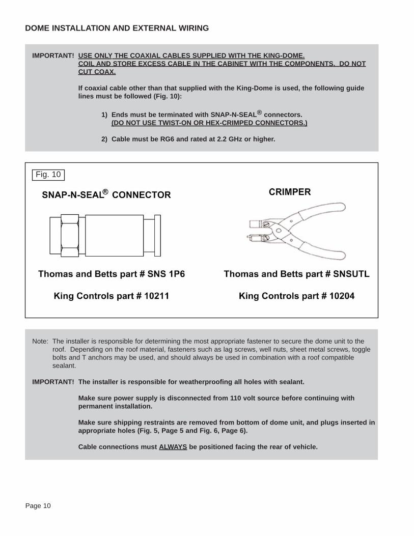
IMPORTANT! USE ONLY THE COAXIAL CABLES SUPPLIED WITH THE KING-DOME.COIL AND STORE EXCESS CABLE IN THE CABINET WITH THE COMPONENTS. DO NOTCUT COAX.
If coaxial cable other than that supplied with the King-Dome is used, the following guidelines must be followed (Fig. 10):
1) Ends must be terminated with SNAP-N-SEAL® connectors.(DO NOT USE TWIST-ON OR HEX-CRIMPED CONNECTORS.)
2) Cable must be RG6 and rated at 2.2 GHz or higher.

1. Mount the dome unit. Use the pre-drilled holes in the mounting feet as a guide to installthe fasteners into the roof. Use additional fasteners whenever necessary.
2. Test that the dome unit is secure by pulling upward from each foot location.
3. Fill end of coaxial cable that will connect to the MAIN port on the dome unit with suppliedgrease (Fig. 11).
4. Connect coaxial cable to the MAIN port and tighten connection.
If using a second receiver, fill end of second coaxial cable and connect it to the portlabeled AUX. Tighten connection.
DO NOT OVER TIGHTEN CONNECTIONS.
Page 11
Note. The King-Dome is wired for a dual LNB. There are two coaxial ports on the back of the dome unit. Theone labeled “MAIN” MUST be connected to the Tuner (IDB) in vehicle. The one labeled “AUX” can be usedfor an additional receiver (see page 15).
There are three lengths of coaxial cable supplied. The 7’ is used to connect the tuner to the receiver. Thelonger two are for connecting the dome unit to the receivers. Use the shorter of the two for the closestreceiver, and the longer one for the receiver farthest away.
IMPORTANT! You must fill the ends of the external coaxial cables with the supplied dielectric grease.
Fig. 11IMPORTANT!
You must fill the ends of theexternal coaxial cables with the
supplied dielectric grease.
Coax connections should be snug.
DO NOT OVER TIGHTEN!

7. Remove blue protective sheet and red “position to rear” sticker from the dome unit.
Page 12
Fig. 12 TYPICAL ROOF INSTALLATION - OVERHEAD VIEW
IMPORTANT!Sealant must be roof
compatible.
5. Run coax from the back of the dome unit to the roof edge, then along edge to locationwhere coax will be fed into the vehicle. (If installing an optional second receiver, runauxiliary coax to location where it will enter the vehicle.) Secure wiring to roof every 12-18 inches (Fig. 12).
6. Drill 3/4” hole through the roof and into the cabinet where main receiver is stored. Feedcoax down through hole. Seal opening with roof compatible sealant so that it is entirelywaterproof (inside and outside of the 3/4” hole). Fasten cable entry cover to roof. Sealmounting holes, perimeter of cover and cable opening so they are completely waterproof.(Fig. 12).
IMPORTANT! Sealant must be roof compatible.
Installer is responsible for determining proper roof compatible fasteners for cable entrycover.
Roof holes for cables must be sealed so they are entirely waterproof. Mounting holes,perimeter of cable entry cover and cable opening of cable entry cover must be sealed so they are entirely waterproof.

Page 13
This page intentionally left blank.

Page 14
INTERNAL WIRING (Fig. 13)
1. Make all connections as shown in the wiring diagram. ALWAYS CONNECT THEPOWER SUPPLY LAST.
IMPORTANT! The coax cable from the “MAIN” port on the dome unit MUST be connected to the Tuner(IDB) in the vehicle.
Coax connections should be snug. DO NOT OVER TIGHTEN.
CONNECT POWER SUPPLY LAST. When connecting the power supply cable to the tuner,push in the power supply cable end until it is flush against the back of the tuner.
Note: When the power supply is connected, the controller should turn on for 3 seconds and then turn off. If thecontroller stays on, Press the ENTER and “-” buttons simultaneously to turn unit off.
ELECTRICAL HAZARD WARNING!
The coaxial cable that connects the dome unit to the tuner carries a 24 volt electricalcurrent. Exercise extreme caution when handling this cable. Do not cut, break, or splicethis line. Do not insert or connect any devices such as splitters or any other device for anyreason. This line is not compatible with any other equipment. Damage will occur to anydevice other than the dome unit if connected to the antenna port on the tuner.

Page 15
Fig. 13
IMPORTANT! AVOID SHARP BENDS WHEN ROUTING COAX.
9762-LP WIRING DIAGRAMDIRECTV, Dish Network and ExpressVuStandard Programming - 1 or 2 receivers

Page 16
1. Use the Faceplate as a guide to mark and cut out the mounting cavity, and if necessary,mark and drill the mounting holes (Fig. 14).
2. Mount Faceplate in wall with supplied screws.
The Faceplate is optional and can be removed as follows: (Fig. 15)
1. Remove 4 screws from Controller.
2. Slide Faceplate off Controller.
3. Replace 4 screws.
Fig. 14
Fig. 15
Note:Depending on the mountingsurface, pilot holes for the
screws may or may not need tobe drilled.
Note: If not using the Faceplate, see Faceplate removal instructions below.
WALL MOUNT FACEPLATE

Page 17
This page intentionally left blank.

IMPORTANT! There must be a clear “line of sight” to the satellite (See Fig. 2, Page 3). Mountains,buildings, trees, telephone poles, etc. can all block the satellite signal from reaching the dish.
Note: This example is for the DTV 101 satellite in Region 2-North Central. The information on your controller willvary depending on the satellite and region you have chosen (see pages 20-21).
SECTION 4 OPERATION
Note: The Trac-King must remain powered on to maintaina signal. If you are going to be stationary and wishto continue watching TV, DO NOT TURN THESYSTEM OFF.
Page 18

Page 19
AUTOMATIC SATELLITE SWITCHING
1. Simply choose your desired channel using the receiver’s remote control. The Trac-Kingwill automatically switch to the appropriate satellite.
Note: For better performance when using the automatic satellite switching feature, change channels by selectingyour program from the channel guide rather than channel surfing.
It is common for the picture to pixel or display an error message when the antenna is switching betweensatellites, or the signal has been temporarily blocked. PLEASE BE PATIENT. THE PICTURE WILL RETURN.
If an error message appears for an extended period, selecting CANCEL may help clear the message more quickly.
Note: For DIRECTV switching options see page 22.
For Dish Network - ExpressVu switching options see page 23.

Note: The King Controls HD TV Converter Box (#9747 or #9747-AM) is requiredto receive HD programming from the DIRECTV satellite at 110.
SET SATELLITE SERVICE
Page 20
SATELLITE LIBRARY
DTV 101 DIRECTV at 101
DTV 101/ 110 hd DIRECTV HDTV at 101 and 110
DTV 101/ 119 DIRECTV HDTV at 101 and 119
Sat 110 Dish Network at 110
Sat 119 Dish Network at 119
DISH 61 Dish Network at 61
DISH 129 Dish Network at 129
DISH 148 Dish Network at 148
DISH 110/119 Dish Network at 110 and 119
DISH 1000 Dish Network HDTV at 110, 119, and 129
DISH 1000a Dish Network HDTV at 61, 110, and 119
EXPVU 82 Bell ExpressVu at 82
EXPVU 91 Bell ExpressVu at 91
BEV 82/ 91 Bell ExpressVu at 82 and 91 (not available on all units)

Page 21
REGION OPTIONS:
1 NORTH WEST2 NORTH CENTRAL3 NORTH EAST4 CENTRAL WEST5 MIDDLE CENTRAL6 CENTRAL EAST7 SOUTH WEST8 SOUTH CENTRAL9 SOUTH EAST
ALL REGIONS0 RECALIBRATE
Note: To reduce satellite acquisition time, you can set your current region.
SET REGION (OPTIONAL)

Page 22
SECTION 5 AUTOMATIC SATELLITE SWITCHINGDIRECTV
To receive programming from the DIRECTV 101 satellite only, your receiver must be set forround dish-1 satellite (do this through the receiver’s satellite set-up menu screens).
To automatically switch between the 101 and 119 satellites for DIRECTV, choose the DTV101/119 option (see procedure on page 20), and make sure your receiver is set for oval dish-2 satellites (do this through the receiver’s satellite set-up menu screens).
To receive DIRECTV HD programming with your Trac-King antenna requires the purchase of anoptional HD converter kit # 9747. This will allow you to receive the specially formatted HDsignals from DIRECTV’s 110° satellite and automatically switch between satellites 101/110 and101/119 when simply changing channels.
The automatic satellite switching feature can be active on 1 or more receivers depending on howthe system is installed. The two options for automatic satellite switching are as follows:
Switching from master receiver only
To enable automatic satellite switching from the main satellite receiver only, use the wiringconfiguration found on page 30. This allows only the receiver connected to the tuner to providethe switching command to the antenna when a channel from the alternate satellite is selected. If you plan to use this switching method with (2) HDTV receivers, a second HD converter #9747is required (page 31).
Switching from any receiver
To automatically switch satellites from any receiver location when the installation includes 2 ormore satellite receivers, a multi-switch (#1810) must be installed in-line (see page 32). Thisallows any of the receivers to provide the switching command to the antenna when a channelfrom the alternate satellite is selected, provided that all other receivers are tuned to a channel onthe 101 satellite.
Note: To learn more about receiving HDTV programming with your Trac-King antenna, contact your localauthorized King-Dome dealer or call King Controls at (800) 982-9920.
IMPORTANT! This King-Dome will receive available HDTV programming from DIRECTV Ku band satellitesat 101°, 110° and 119° with the properly installed HD converter accessory. It will not receivechannels broadcast from DIRECTV’s Ka band satellites at 99° and 103°.

Page 23
SECTION 6 AUTOMATIC SATELLITE SWITCHINGDish Network - ExpressVu
BELL EXPRESSVU HD
The Trac-King will automatically switch between the 82 and 91 satellites for Bell ExpressVu byusing the receiver’s remote control, after the receiver has been properly configured. Follow theinstructions on pages 28-29.
DISH 500 FOR DISH NETWORK
The Trac-King will automatically switch between the 110 and 119 satellites for Dish Network byusing the receiver’s remote control, after the receiver has been properly configured. Follow theinstruction on pages 24-25.
DISH 1000/1000a FOR DISH NETWORK HDTV
Dish Network HD programming is broadcast from 4 satellites (61,110,119,129). The 61 and 129satellites broadcast identical programming. (The 61 is generally stronger in the eastern U.S. andthe 129 in the western U.S.) The map below shows the approximate coverage for each satellite.
Your Trac-King antenna can be easily configured to work with two different satellites trios (DISH1000a: 61,110,119 or DISH 1000: 110,119,129) as you travel from one coverage area to another.By choosing the appropriate trio that includes either the 61 or the 129 based on where you are,you can receive all of your desired programming. Follow the instructions on pages 26-27.
Note: This map is anapproximation only. Which trioworks best in a given location
may differ from what is indicatedon the map.
SATELLITES 61 AND 129 COVERAGE MAP

Page 24
DISH 500 for DISH NETWORK
IMPORTANT! In order for all receivers to work properly, each one must be configured separately whileconnected to the MAIN port on the Trac-King.
If you do not have a clear view of both satellites, the switch will not load.
King Controls recommends using a Dish Network model 311 receiver for automatic satellite switching.
Note: The SW21 switch is a receiver software configuration that is loaded into the receiver after running a checkswitch test with the dish locked on and configured for Dish 500 switching mode.
This is a one time procedure and will not need to be repeated after successful installation, unless the check switch test is run again while connected to a home dish system.

Page 25
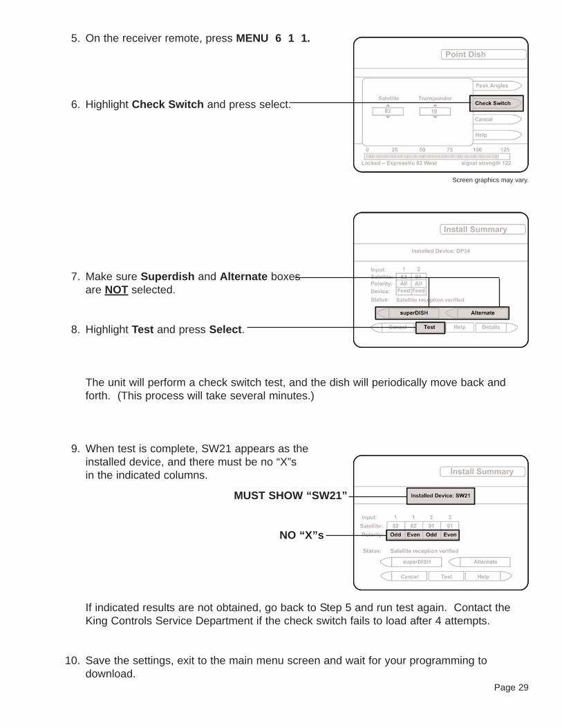
5. On the receiver remote, press MENU 6 1 1.
6. Highlight Check Switch and press select.
7. Make sure Superdish and Alternate boxes are NOT selected.
8. Highlight Test and press Select.
The unit will perform a check switch test, and the dish will periodically move back andforth. (This process will take several minutes.)
9. When test is complete, SW21 appears as the installed device, and there must be no “X”s in the indicated columns.
If indicated results are not obtained, go back to Step 5 and run test again. Contact theKing Controls Service Department if the check switch fails to load after 4 attempts.
10. Save the settings, exit to the main menu screen and wait for your programming todownload.
MUST SHOW “SW21”
NO “X”s
Screen graphics may vary.

DISH 1000/1000a for Dish Network HDTV
IMPORTANT! In order for all receivers to work properly, each one must be configured separately whileconnected to the MAIN port on the Trac-King.
If you do not have a clear view of all three satellites, the switch will not load.
King Controls recommends using a Dish Network model VIP211 HDTV receiver forautomatic satellite switching.
Note: The SW64 switch is a receiver software configuration that is loaded into the receiver after running a checkswitch test with the dish locked on and configured for Dish 1000 or 1000a switching mode.
This is a one time procedure and will not need to be repeated after successful installation, unless the check switch test is run again while connected to a home dish system, or if you travel to another area andneed to change the selected trio of satellites.
Page 26
Note: Dish 1000 = satellites 110, 119, 129
Dish 1000a = satellites 61, 110, 119
(See map on page 23.)

Page 27
5. On the receiver remote, press MENU 6 1 1.
6. Highlight Check Switch and press select.
7. Make sure Superdish and Alternate boxes are NOT selected.
8. Highlight Test and press Select.
The unit will perform a check switch test, and the dish will periodically move back andforth. (This process will take several minutes.)
9. When test is complete, SW64 appears as the installed device, and there must be no “X”s in the indicated columns.
If indicated results are not obtained, go back to Step 5 and run test again. Contact theKing Controls Service Department if the check switch fails to load after 4 attempts.
10. Save the settings, exit to the main menu screen and wait for your programming todownload.
MUST SHOW “SW64”
NO “X”s
Screen graphics may vary.

Page 28
IMPORTANT! This feature is not available on all units. If your unit has this feature, “BEV 82/91” will belisted in the satellite library on your controller’s display (see page 20).
Some units can be upgraded with this feature. Please call the King Controls servicedepartment with the serial number of your Trac-King to determine if this feature will workwith your unit.
In order for all receivers to work properly, each one must be configured separately whileconnected to the MAIN port on the King-Dome.
If you do not have a clear view of both satellites, the switch will not load.
Note: The SW21 switch is a receiver software configuration that is loaded into the receiver after running a checkswitch test with the dish locked on and configured for ExpressVu HD switching mode.
This is a one time procedure and will not need to be repeated after successful installation, unless the checkswitch test is run again while connected to a home dish system.
BELL EXPRESSVU HD
Page 29
5. On the receiver remote, press MENU 6 1 1.
6. Highlight Check Switch and press select.
7. Make sure Superdish and Alternate boxes are NOT selected.
8. Highlight Test and press Select.
The unit will perform a check switch test, and the dish will periodically move back andforth. (This process will take several minutes.)
9. When test is complete, SW21 appears as the installed device, and there must be no “X”s in the indicated columns.
If indicated results are not obtained, go back to Step 5 and run test again. Contact theKing Controls Service Department if the check switch fails to load after 4 attempts.
10. Save the settings, exit to the main menu screen and wait for your programming todownload.
MUST SHOW “SW21”
NO “X”s
Screen graphics may vary.

Page 30
(1) HD receiver and (1) standard receiverSwitching from master receiver only
Note: Requires HDTV converter #9747 and other HDTV components (purchased separately). Call King Controlsfor more information.
SECTION 7 DIRECTV HDTV CONNECTIONS
Note:When configured for automatic
switching from the master receiveronly, you must manually switch
satellites for the secondary receiverusing the antenna controller.

Page 31
(2) HD receiversSwitching from master receiver only
Note: Requires (2) HDTV converters #9747 and other HDTV components (purchased separately). Call KingControls for more information.
Note:When configured for automatic
switching from the master receiveronly, you must manually switch
satellites for the secondary receiverusing the antenna controller.

Page 32
Note:To automatically switch betweensatellites using any receiver, tuneall other receivers to a channel on
the 101 satellite.
(2) or more HD receiversSwitching from any receiver
Note: Requires HDTV converter #9747 and other HDTV components (purchased separately). Call King Controlsfor more information.

This page intentionally left blank.
Page 33

Page 34
SECTION 8 TROUBLESHOOTING
Controller does not power up.
Controller remains in one of thefollowing conditions:
POWER TRIP
ANT COM ERROR?
TUNER COM ERROR?
LOAD ERROR
LOADING PLEASE WAIT
Unplug tuner for 10 seconds, then plug back in.
Check coax cables and connections between tuner and dome unit.
Inspect all coax cables for kinks and verify connections are snug but notoverly tight (inside and outside dome unit).
Controller remains in thefollowing condition:
POWER UP PLEASE WAIT
Verify voltage on coax at dome unit is 24 volts.
Check: tuner is connected to power supply.
controller is connected to tuner.
power supply is plugged into 110 VAC outlet.
SYMPTOM POSSIBLE SOLUTION
Controller displays AZ FAULT.Dish cannot rotate
Controller displays EL FAULT. Make sure shipping tie strap is removed.
Disconnect power supply for 15 seconds, then reconnect.
Perform Mechanical Calibration (page 38).
Restart system. If problem persists, perform OPTION 21 RE-INITIALIZE and 0-RECALIBRATE (pages 36-37).
Reseat ribbon cables (inside dome unit).
Make sure shipping bolts are removed.
Make sure shipping tie strap is removed.
Disconnect power supply for 15 seconds, then reconnect.
Perform Mechanical Calibration (page 38).
Perform OPTION 21 RE-INITIALIZE and 0-RECALIBRATE (pages 36-37).
Reseat ribbon cables (inside dome unit).

Page 35
SYMPTOM POSSIBLE SOLUTION
Only getting signal on 1/2 oftransponders.
Kinked or sharply bent coax cable.
Verify coax cables are properly terminated with SNAP-N-SEAL®
connectors only.
Verify receiver is operating properly.
Verify LNB type is set correctly.
Unit never locks on or locks onand drifts off of satellite.
Atmospheric moisture. Unit will lock on as weather improves.
Check for obstruction in sky in direction of satellite. Select another satelliteand verify unit locks on.
Verify coax cables are properly terminated with SNAP-N-SEAL®
connectors only.
Perform OPTION 21 RE-INITIALIZE and 0-RECALIBRATE (pages 36-37).
Inspect all coax cables for kinks and verify connections are snug but notoverly tight (inside and outside dome unit).
Perform Temperature Calibration (CALL KING CONTROLS FIRST).
Compass stick bad or not connected.
Check for line of sight obstruction.
Check for low signal strength.
Current location might be out of service area.
Select alternate trio of satellites (SW64) and try again.
Atmospheric moisture. Wait for weather to improve.
Can’t get SW21 or SW 64switch to load properly.
Disconnect DIRECTV HDTV Converter.Trying to load the SW21 orSW64 results in error or nosatellite.

Page 36
OPTION 21 RE-INITIALIZE and 0 RECALIBRATE

Page 37

Page 38
MECHANICAL CALIBRATION
IMPORTANT! The Trac-King must remain perfectly still and level during the mechanical calibration. Donot have the vehicle running during the process.
The Trac-King must be running. (NOT IN IDLE/HOLD)

Page 39
The King-Dome Satellite System has been designed to be maintenance and trouble free.
For optimum signal strength, keep the dome clean from dirt, bugs, and other debris. Periodicwashing of the dome with mild soap and water is recommended.
If you plan on storing your vehicle for long periods of time, it is recommended that the system beput through a search procedure on a quarterly basis to keep all moving parts in good workingorder.
If you have any comments or questions, please contact the King Controls Service Department at(800) 982-9920, or email King Controls at [email protected]
Rain Fade
Rain or dew on the dome can cause signal interference and make the digital picture freeze, pixelor go out altogether. This loss of signal is commonly referred to as “rain fade” and is caused bythe combination of water in the atmosphere and water on the dome surface.
To minimize this issue and eliminate the effects of water on the dome, apply King Controls Dome Magic® rain fade solution to the dome. This will prevent water from sticking to the domesurface and blocking the signal. For additional details on Dome Magic® rain fade solution pleasecontact your authorized King-Dome dealer or call King Controls at (800) 982-9920.
SECTION 9 MAINTENANCE
Single Application Packet #1830-SP Spray Can #1830
Note: Dome Magic® will discolor black domes or domes painted a dark color.

Page 40
Every King-Dome Satellite System is thoroughly inspected and tested before leaving the factory. It is covered by atwo year parts and one year labor limited warranty from the date of original purchase. This warranty does not coverinstallation and external wiring or refurbished units.
Should any trouble develop during the warranty period, contact King Controls. Only King Controls and certifieddealers are authorized to perform warranty evaluations and repairs.
If it is determined that the unit needs to be returned, return COMPLETE product, freight prepaid, to : King Controls, 11200 Hampshire Ave. S. Bloomington, MN 55438-2453. If inspection shows the trouble iscaused by defective workmanship or material, King Controls will repair (or at its option, replace) without charge.
This warranty does not apply where:
- The product has been abused, misused, improperly installed or improperly maintained.- Repairs have been made or attempted by others that are not certified by King Controls to do such repairs.- Repairs are required because of normal wear and tear.- Alterations have been made to the product.
In no event shall King Controls be liable for any indirect, incidental, or consequential damages from thesale or use of the product. This disclaimer applies both during and after the term of the warranty.
King Controls disclaims liability for any implied warranties, including implied warranties of“merchantability” and “fitness for a specific purpose,” after the one year term of this warranty.
This warranty gives you specific legal rights, and you may also have other rights, which vary from state to state.Some states do not allow the exclusion or limitation of incidental or consequential damages, so the above limitationor exclusion may not apply to you. Some states do not allow limitations on how long an implied warranty lasts, sothe above limitation may not apply to you.
SECTION 10 LIMITED WARRANTY


11200 Hampshire Avenue South, Bloomington, MN 55438-2453Phone: (800) 982-9920 Fax: (952) 922-8424
www.kingcontrols.com
Trac-King


![Material de Apoio 21 10-Injecao Eletronica2[59894][9762]](https://static.fdocuments.net/doc/165x107/55cf9963550346d0339d2268/material-de-apoio-21-10-injecao-eletronica2598949762.jpg)