TR 103 133 - V1.1.1 - Methods for Testing and Specification - ETSI
123
ETSI TR 103 133 V1.1.1 (2013-03) Methods for Testing and Specification (MTS); Model-Based Testing (MBT); Application of MBT in ETSI case studies Technical Report
Transcript of TR 103 133 - V1.1.1 - Methods for Testing and Specification - ETSI

ETSI TR 103 133 V1.1.1 (2013-03)
Methods for Testing and Specification (MTS); Model-Based Testing (MBT);
Application of MBT in ETSI case studies
�
Technical Report

ETSI
ETSI TR 103 133 V1.1.1 (2013-03) 2
Reference DTR/MTS-141 MBT_CaseStudies
Keywords methodology, model, testing
ETSI
650 Route des Lucioles F-06921 Sophia Antipolis Cedex - FRANCE
Tel.: +33 4 92 94 42 00 Fax: +33 4 93 65 47 16
Siret N° 348 623 562 00017 - NAF 742 C
Association à but non lucratif enregistrée à la Sous-Préfecture de Grasse (06) N° 7803/88
Important notice
Individual copies of the present document can be downloaded from: http://www.etsi.org
The present document may be made available in more than one electronic version or in print. In any case of existing or perceived difference in contents between such versions, the reference version is the Portable Document Format (PDF).
In case of dispute, the reference shall be the printing on ETSI printers of the PDF version kept on a specific network drive within ETSI Secretariat.
Users of the present document should be aware that the document may be subject to revision or change of status. Information on the current status of this and other ETSI documents is available at
http://portal.etsi.org/tb/status/status.asp
If you find errors in the present document, please send your comment to one of the following services: http://portal.etsi.org/chaircor/ETSI_support.asp
Copyright Notification
No part may be reproduced except as authorized by written permission. The copyright and the foregoing restriction extend to reproduction in all media.
© European Telecommunications Standards Institute 2013.
All rights reserved.
DECTTM, PLUGTESTSTM, UMTSTM and the ETSI logo are Trade Marks of ETSI registered for the benefit of its Members. 3GPPTM and LTE™ are Trade Marks of ETSI registered for the benefit of its Members and
of the 3GPP Organizational Partners. GSM® and the GSM logo are Trade Marks registered and owned by the GSM Association.

ETSI
ETSI TR 103 133 V1.1.1 (2013-03) 3
Contents
Intellectual Property Rights ................................................................................................................................ 5
Foreword ............................................................................................................................................................. 5
Introduction ........................................................................................................................................................ 5
1 Scope ........................................................................................................................................................ 6
2 References ................................................................................................................................................ 6
2.1 Normative references ......................................................................................................................................... 6
2.2 Informative references ........................................................................................................................................ 6
3 Definitions and abbreviations ................................................................................................................... 7
3.1 Definitions .......................................................................................................................................................... 7
3.2 Abbreviations ..................................................................................................................................................... 7
4 Modelling and test generation tools used ................................................................................................. 9
4.1 Microsoft® Spec Explorer ................................................................................................................................. 9
4.2 Conformiq Designer™ ....................................................................................................................................... 9
4.3 sepp.med MBTsuite.......................................................................................................................................... 10
4.4 Fraunhofer FOKUS MDTester ......................................................................................................................... 10
5 Case study 1: ATM academic example .................................................................................................. 11
5.1 General description of case study 1 .................................................................................................................. 11
5.1.1 Overview of case study 1 ............................................................................................................................ 11
5.1.2 Abstract model of case study 1 ................................................................................................................... 11
5.2 Applying Microsoft® Spec Explorer to case study 1 ....................................................................................... 12
5.2.1 Modelling case study 1 with Spec Explorer ................................................................................................ 12
5.2.2 Spec Explorer model of case study 1 .......................................................................................................... 12
5.2.3 Generating test cases with Spec Explorer for case study 1 ......................................................................... 13
5.2.4 Evaluation ................................................................................................................................................... 14
5.3 Applying Conformiq Designer™ to case study 1 ............................................................................................. 14
5.3.1 Modelling case study 1 with Conformiq Designer™.................................................................................. 15
5.3.2 Conformiq Designer™ model of case study 1 ............................................................................................ 15
5.3.3 Generating test cases with Conformiq Designer™ for case study 1 ........................................................... 16
5.3.4 Evaluation ................................................................................................................................................... 17
5.4 Applying sepp.med MBTsuite to case study 1 ................................................................................................. 18
5.4.1 Modelling case study 1 with sepp.med MBTsuite ...................................................................................... 18
5.4.2 sepp.med MBTsuite model of case study 1 ................................................................................................ 19
5.4.3 Generating test cases with sepp.med MBTsuite for case study 1 ............................................................... 21
5.4.4 Evaluation ................................................................................................................................................... 24
5.5 Applying FOKUS MDTester to case study 1 ................................................................................................... 24
5.5.1 Modelling case study 1 with FOKUS MD Tester ....................................................................................... 24
5.5.2 FOKUS MD Tester model of case study 1 ................................................................................................. 25
5.5.3 Generating test cases with FOKUS MD Tester for case study 1 ................................................................ 28
5.5.4 Evaluation ................................................................................................................................................... 30
6 Case study 2: ITS location services ........................................................................................................ 31
6.1 General description of case study 2 .................................................................................................................. 31
6.1.1 Overview of case study 2 ............................................................................................................................ 31
6.1.2 Common base for modelling of case study 2 .............................................................................................. 31
6.1.3 ETSI test cases for case study 2 .................................................................................................................. 32
6.2 Applying Microsoft® Spec Explorer to case study 2 ....................................................................................... 33
6.2.1 Modelling case study 2 with Spec Explorer ................................................................................................ 33
6.2.2 Spec Explorer model of case study 2 .......................................................................................................... 35
6.2.3 Generating test cases with Spec Explorer for case study 2 ......................................................................... 38
6.2.4 Evaluation ................................................................................................................................................... 51
6.3 Applying Conformiq Designer™ to case study 2 ............................................................................................. 53
6.3.1 Modelling case study 2 with Conformiq Designer™.................................................................................. 54
6.3.2 Conformiq Designer™ model of case study 2 ............................................................................................ 54

ETSI
ETSI TR 103 133 V1.1.1 (2013-03) 4
6.3.3 Generating test cases with Conformiq Designer™ for case study 2 ........................................................... 58
6.3.3.1 Generating test cases for the Test Purposes .......................................................................................... 58
6.3.3.2 Generating test cases for model details ................................................................................................. 58
6.3.4 Evaluation ................................................................................................................................................... 59
6.3.4.1 Evaluation of the test suite generated to cover the Test Purposes ......................................................... 59
6.4 Applying sepp.med MBTsuite to case study 2 ................................................................................................. 60
6.4.1 Modelling case study 2 with sepp.med MBTsuite ...................................................................................... 60
6.4.2 sepp.med MBTsuite model of case study 2 ................................................................................................ 61
6.4.3 Generating test cases with sepp.med MBTsuite for case study 2 ............................................................... 61
6.4.4 Evaluation ................................................................................................................................................... 62
6.5 Applying FOKUS MD Tester to case study 2 .................................................................................................. 62
6.5.1 Modelling case study 2 with FOKUS MD Tester ....................................................................................... 62
6.5.2 FOKUS MD Tester model of case study 2 ................................................................................................. 62
6.5.3 Generating test cases with FOKUS MD Tester for case study 2 ................................................................ 64
6.5.4 Evaluation ................................................................................................................................................... 65
7 Case study 3: Diameter........................................................................................................................... 67
7.1 General description of case study 3 .................................................................................................................. 67
7.1.1 Overview of case study 3 ............................................................................................................................ 67
7.1.2 Abstract model of case study 3 ................................................................................................................... 68
7.1.3 ETSI test cases for case study 3 .................................................................................................................. 68
7.2 Applying Microsoft® Spec Explorer to case study 3 ....................................................................................... 69
7.2.1 Modelling case study 3 with Spec Explorer ................................................................................................ 69
7.2.2 Spec Explorer model of case study 3 .......................................................................................................... 71
7.2.3 Generating test cases with Spec Explorer for case study 8 ......................................................................... 73
7.2.4 Evaluation ................................................................................................................................................... 78
7.3 Applying Conformiq Designer™ to case study 3 ............................................................................................. 83
7.3.1 Modelling case study 3 with Conformiq Designer™.................................................................................. 83
7.3.2 Conformiq Designer™ model of case study 3 ............................................................................................ 83
7.3.3 Generating test cases with Conformiq Designer™ for case study 3 ........................................................... 86
7.3.4 Evaluation ................................................................................................................................................... 87
7.4 Applying sepp.med MBTsuite to case study 3 ................................................................................................. 88
7.4.1 sepp.med MBTsuite model of case study 3 ................................................................................................ 88
7.4.2 Generating test cases with sepp.med MBTsuite for case study 3 ............................................................... 89
7.4.3 Evaluation ................................................................................................................................................... 90
7.5 Applying FOKUS MD Tester to case study 3 .................................................................................................. 91
7.5.1 Modelling case study 3 with FOKUS MD Tester ....................................................................................... 91
7.5.2 FOKUS MD Tester model of case study 3 ................................................................................................. 91
7.5.3 Generating test cases with FOKUS MD Tester for case study 3 ................................................................ 94
7.5.4 Evaluation ................................................................................................................................................... 94
8 Evaluation of all case studies ................................................................................................................. 94
Annex A: Detailed evaluation of case studies ...................................................................................... 95
A.1 Evaluation of case study 1: ATM academic example ............................................................................ 95
A.1.1 ATM case study evaluation with Spec Explorer .............................................................................................. 95
A.1.2 ATM case study evaluation with MDTester ..................................................................................................... 96
A.2 Evaluation of case study 2: ITS location services .................................................................................. 99
A.2.1 ITS location services case study evaluation with Spec Explorer ...................................................................... 99
A.2.2 ITS location services case study evaluation with Conformiq Designer™ ...................................................... 101
A.2.3 ITS location services case study evaluation with sepp.med MBTsuite .......................................................... 103
A.3 Evaluation of case study 3: Diameter ................................................................................................... 115
A.3.1 Diameter case study evaluation with Spec Explorer ...................................................................................... 115
A.3.2 Diameter case study evaluation with Conformiq Designer™ ........................................................................ 118
A.3.3 Diameter case study evaluation with MDTester ............................................................................................. 118
Annex B: Electronic annex: Models and test cases for the tools used for the case studies ............ 122
History ............................................................................................................................................................ 123

ETSI
ETSI TR 103 133 V1.1.1 (2013-03) 5
Intellectual Property Rights IPRs essential or potentially essential to the present document may have been declared to ETSI. The information pertaining to these essential IPRs, if any, is publicly available for ETSI members and non-members, and can be found in ETSI SR 000 314: "Intellectual Property Rights (IPRs); Essential, or potentially Essential, IPRs notified to ETSI in respect of ETSI standards", which is available from the ETSI Secretariat. Latest updates are available on the ETSI Web server (http://ipr.etsi.org).
Pursuant to the ETSI IPR Policy, no investigation, including IPR searches, has been carried out by ETSI. No guarantee can be given as to the existence of other IPRs not referenced in ETSI SR 000 314 (or the updates on the ETSI Web server) which are, or may be, or may become, essential to the present document.
Foreword This Technical Report (TR) has been produced by ETSI Technical Committee Methods for Testing an Specification (MTS).
Introduction The present document represents a case study report on Model Based Testing (MBT). Four state-of-the-art MBT tools have been applied to one small academic example and two case studies provided by two ETSI technical committees. The document describes case studies, their modelling with the different tools and presents the results of the test generation experiments. For two of the case studies, the generated test suites are compared with the manually developed ETSI test suites. The evaluation results may give some indication of how well current state-of-the-art MBT tools can support the test suite development process at ETSI.
The aim of the present document is not to evaluate the four MBT tools applied in these case studies. The tools have been developed for different application areas and are tailored to those application areas and none of the tools have been developed to specifically support the ETSI standards development process.
It should be noted that the contents of the present document reflects expertise and experience of the investigators with modeling, used MBT tools and the standard documents describing the case studies. The investigators cannot guarantee that the usage of the used MBT tools is always optimal and that the models, representing interpretations of the standards, are always adequate.
NOTE: The readers of the document will notice that the details in some figures are not legible. This is a deliberate choice as the details of the figures are not of importance and only the structure of the state machines was highlighted. However, the figures were created as screenshots of models given in the electronic annex. Thus, a reader that wants to see the details can visualize them by viewing the models with respective modelling tools.

ETSI
ETSI TR 103 133 V1.1.1 (2013-03) 6
1 Scope The present document records the application of MBT and the ETSI MBT methodology in a number of ETSI case studies from the ITS and IMS domain for test specification development. It can be seen as an informal supplement of the following documents:
• DEG/MTS-00142: "MBT methodology Model-Based Testing (MBT); Methodology for standardized test specification development" [i.13].
• ETSI ES 202 951 V1.1.1 (2011-07): "Methods for Testing and Specification (MTS); Model-Based Testing (MBT); Requirements for Modelling Notations" [i.14].
2 References References are either specific (identified by date of publication and/or edition number or version number) or non-specific. For specific references, only the cited version applies. For non-specific references, the latest version of the referenced document (including any amendments) applies.
Referenced documents which are not found to be publicly available in the expected location might be found at http://docbox.etsi.org/Reference.
NOTE: While any hyperlinks included in this clause were valid at the time of publication ETSI cannot guarantee their long term validity.
2.1 Normative references The following referenced documents are necessary for the application of the present document.
Not applicable.
2.2 Informative references The following referenced documents are not necessary for the application of the present document but they assist the user with regard to a particular subject area.
[i.1] ETSI TS 102 636-4-1 (V1.1.1): "Intelligent Transport System (ITS); Vehicular communications; GeoNetworking; Part 4: Geographical addressing and forwarding for point-to-point and point-to-multipoint communications; Sub-part 1: Media-Independent Functionality".
[i.2] ETSI TS 102 871-2 (V1.1.1): "Intelligent Transport Systems (ITS); Testing; Conformance test specifications for GeoNetworking ITS-G5; Part 2: Test Suite Structure and Test Purposes (TSS&TP)".
[i.3] ETSI TS 129 214 (V10.6.0): "Universal Mobile Telecommunications System (UMTS); LTE; Policy and charging control over Rx reference point (3GPP TS 29.214)".
[i.4] ETSI TS 101 580-2 (V1.1.1): "IMS Network Testing (INT); Diameter Conformance testing for Rx interface; Part 2: Test Suite Structure (TSS) and Test Purposes (TP)".
[i.5] IETF RFC 4005 (2005): "Diameter Network Access Server Application".
[i.6] Conformiq™ Inc.: Company Website, (last visited 27.08.2012).
NOTE: Available at http://www.conformiq.com/.
[i.7] Microsoft® Corporation: Company Website, (last visited 27.08.2012).
NOTE: Available at http://www.microsoft.com/.

ETSI
ETSI TR 103 133 V1.1.1 (2013-03) 7
[i.8] Microsoft® Corporation: Microsoft® Developer Network Web pages for Spec Explorer, (last visited 29.08.2012).
NOTE: Available at http://msdn.microsoft.com/en-us/library/ee620411.
[i.9] Conformiq™ Inc.: Conformiq™ Inc. products Web page for Conformiq Designer™, (last visited 29.08.2012).
NOTE: Available at http://www.conformiq.com/products/conformiq-designer.
[i.10] sepp.med GmbH: Company Website, (last visited 29.08.2012).
NOTE: Available at http://www.seppmed.de/.
[i.11] sepp.med GmbH: sepp.med products Web page for MBTsuite, (last visited 29.08.2012).
NOTE: Available at http://www.seppmed.de/produkte/mbtsuite.html.
[i.12] Fraunhofer FOKUS competence center MOTION: MOTION Web page, (last visited 30.08.2012).
NOTE: Available at http://www.fokus.fraunhofer.de/en/motion/index.html.
[i.13] ETSI DEG/MTS-00142: "MBT methodology Model-Based Testing (MBT); Methodology for standardized test specification development".
[i.14] ETSI ES 202 951: "Methods for Testing and Specification (MTS); Model-Based Testing (MBT); Requirements for Modelling Notations".
[i.15] ETSI TS 129 213: "Digital cellular telecommunications system (Phase 2+); Universal Mobile Telecommunications System (UMTS); LTE; Policy and charging control signalling flows and Quality of Service (QoS) parameter mapping (3GPP TS 29.213)".
[i.16] ETSI TS 129 212: "Universal Mobile Telecommunications System (UMTS); LTE; Policy and Charging Control (PCC); Reference points (3GPP TS 29.212)".
[i.17] ISO 9646-1: "Information technology -- Open Systems Interconnection -- Conformance testing methodology and framework -- Part 1: General concepts".
3 Definitions and abbreviations
3.1 Definitions For the purposes of the present document, the terms and definitions given in [i.13] and [i.14] apply.
3.2 Abbreviations For the purposes of the present document, the following abbreviations apply:
AAA AA Answer AAR AA Request AF Application Function ASA Abort Session Answer ASP Abstract Service Primitive ASR Abort Session Request ATM Automated Teller Machine AVP Attribute Value Pair BC Broadcast BPMN Business Process Model and Notation CBF Contention-Based Forwarding CPU Central Processing Unit CSCF Call Session Control Function

ETSI
ETSI TR 103 133 V1.1.1 (2013-03) 8
DE Destination FIFO First In First Out FP GeoNetworking packet to be forwarded FSM Finite State Machine GF Greedy Forwarding GN-PDU GeoNetworking-PDU GPRS General Packet Radio Service GU GeoUnicast HL Hop Limit HST HeaderSubType HT Header type IMS IP Multimedia Subsystem IP Internet Protocol IP-CAN Internet Protocol Connectivity Access Network ITS Intelligent Transport Systems IUT Implementation Under Test LL Link Layer LocT Location Table LPV Local Position Vector LS Location Service LT Lifetime LV Location Vector MBT Model-Based Testing MFR Most Forward within Radius MIB Management Information Base MID MAC ID NH Next Header OSI Open Systems Interconnection PCC Policy and Charging Control PCEF Policy and Charging Enforcement Function PCRF Policy and Charging Rules Function P-CSCF Proxy Call Session Control Function PDU Protocol Data Unit PIN Personal Identification Number PV Position Vector QML Conformiq Modeling Language RAA Re Auth Answer RAR Re Auth Request RAT Radio Access Type RP Received GeoNetworking Packet RTCP Real-Time Transport Control Protocol SDP Session Description Protocol SE Sender SIP Session Initiation Protocol SN Sequence Number SO Source STA Session Termination Answer STF Specialist Task Force STR Session Termination Request SUT System Under Test TC Test Case TCL Tool Command Language TM Trade Mark TP Test Purpose TSB Topologically Scoped Broadcast TSS Test Suite Structure TSS/TP Test Suite Structure/Test Purposes TTCN-3 Testing and Test Control Notation version 3 UC Unicast UE User Equipment UML Unified Modeling Language UTP UML Testing Profile

ETSI
ETSI TR 103 133 V1.1.1 (2013-03) 9
XMI XML Metadata Interchange
4 Modelling and test generation tools used This clause includes an overview of the tools used for modelling and test generation.
4.1 Microsoft® Spec Explorer Spec Explorer for Visual Studio® 2010 (version 3.5.3130.0) is an MBT tool from Microsoft® Coorporation [i.7].
Spec Explorer uses state-oriented model programs that are coded in C#. A Spec Explorer model consists of a number of C# classes, some of which contain rules related with the interface operations and events of the system under test (SUT) and describing its behaviour.
Test generation is performed by exploring the state space of the system model and recording the traces. These traces are transformed into test cases. The main technique for dealing with state space explosion provided by Spec Explorer is scenario-based slicing. A scenario limits the potential executions of the state graph of a model, while preserving the test oracle and other semantic constraints from the system model. When the slicing scenario is combined with the model program during state space exploration the resulting behaviour will be a finite subset of the model program's full, potentially infinite behaviour. Slicing scenarios along with test data used as input for model operations are defined in the scripting language Cord.
Microsoft® Spec Explorer supports modelling on the level of developer by using a general purpose programming language and with Visual Studio® a corresponding development environment. Nevertheless, a modeler can design abstract models by taking into account only the necessary details and using proper adapters to communicate with the SUT.
Up-to-date information on Microsoft® Spec Explorer can be found at [i.8].
4.2 Conformiq Designer™ Conformiq DesignerTM is the MBT tool of ConformiqTM Inc. [i.6]. For the case studies, Conformiq Designer™ version 4.4.1 (build 25561) has been utilized.
Conformiq model programs are written in a combination of Java™ code and UML™ statecharts, i.e. in the Conformiq Modeling Language (QML). The purpose of the models is to describe the expected external behavior of the System Under Test. Java™ code is used to describe how data works in the system, to declare data types and classes, express arithmetics and conditional rules and so on, whereas the UML™ statecharts are used to capture high-level control flow and life cycle of objects.
Conformiq ships with a modeling tool called Conformiq Modeler for defining the state charts, but the tool also supports model imports from various 3rd party modeling tools. The textual part of the model can be created using any text editor. In addition, Conformiq Designer™ provides interfaces to 3rd party requirements and test management tools for tracking the generation of test cases covering all system requirements. The test cases can be exported as human readable test plans for manual execution and in various executable formats for automated test executions.
The whole test generation process of Conformiq Designer™ is driven by semantics: even though there can be statecharts in a Conformiq system model, the graphical structure of the statechart is not used in any fashion to guide test generation, but only the logical meaning of the model. This is in stark contrast with simpler state machine driven test generation approaches where the structure of a (typically only one) state machine is used to generate a sequence of tests that correspond to different paths through the state machine. This is important because only the fully semantics driven approach can tolerate models where the high-level control flow is deeply dependent on data values. The core of Conformiq Designer™ is its semantics driven, symbolic execution based test generation algorithm. The algorithm traverses a part of the (usually infinite) state space of the system model. The explored part in itself is infinite also, but is yet only a part of the whole state space. Conformiq Designer™ uses constraint solving to efficiently handle the unspecified input messages; this is why the approach is also known as symbolic execution as the input messages are represented internally as variables whose values are fixed only later by the constraint solving process.

ETSI
ETSI TR 103 133 V1.1.1 (2013-03) 10
The test generation heuristics that Conformiq Designer™ uses realize various well-known test generation strategies, like, e.g. requirements coverage, transition coverage, branch coverage, atomic condition coverage or boundary value analysis. Because there are often many different ways to put together a set of test cases, the tool uses a combinatorial optimization method to select a collection of test providing a balance between test case length, number of test cases, number of test steps, and independence between different tests. Up-to-date information on Conformiq Designer™ can be found at [i.9].
4.3 sepp.med MBTsuite MBTsuite is the MBT framework from sepp.med GmbH [i.10]. For the case studies, MBTsuite version 2.0.0.v5633_201110210320 has been applied.
For applying MBTsuite, a graphical model has to be provided. In this case study, UML™ state diagrams and activity diagram have been used. Alternatively, BPMN is supported. MBTsuite handles both manual and automated test case instructions. Special tags are available for pre- und postconditions. Test management information like, e.g. priorities, costs or duration may be annotated in the model.
The model is written in a standard 3rd party UML™ tool and imported via XMI into MBTsuite. It is then executed and the execution traces are transformed into test cases. Apart from full path coverage, other generation strategies are available (e.g. guided generation, random generation). If defined in the model, guard conditions and priorities are taken into account at execution. Thus, only logically consistent execution traces are obtained and processed into test cases.
It is possible to filter the execution traces prior to test case generation using several built-in heuristics like, e.g. node coverage, edge coverage, requirement coverage, but also heuristics based on test management information (costs, duration). That way, a minimum set of test cases is obtained that fulfil the defined coverage criteria and test case explosion is avoided. Change management is supported via a built-in comparison of execution traces. Various statistical information regarding the test case generation (e.g. average and maximum test case length, requirement coverage obtained) are available. The execution traces may be stored persistently for further processing.
Generated test cases can be exported in various script languages like, e.g. Borland® SilkTestTM, C/C++, C#, Java™, Perl, or Python, but also as human readable test instructions for manual test execution. Support for TTCN-3 is under development. Traceability to requirements is established within test cases. MBTsuite provides interfaces to 3rd party application lifecycle management tools supporting an effective test management and requirements tracking.
Up-to-date information on MBTsuite can be found at [i.11].
4.4 Fraunhofer FOKUS MDTester MDTester is an academic tool developed by the Fraunhofer FOKUS competence center MOTION [i.12]. MDTester is part of Fokus!MBT, a flexible and extensible test modelling environment based on the UML™ Testing Profile (UTP), which facilitates the development of model-based testing scenarios for heterogeneous application domains.
MDTester is a modelling tool that guides the development of UTP models. UTP models are test models and not system models, i.e. they include tester knowledge like, e.g. setting of test verdicts, knowledge about test components, or default behaviour.
For modelling, MDTester provides the following diagrams types: test requirements diagram (based on class diagram), test architecture diagram (based on class diagram), test data diagram (based on class diagram), test architecture diagram, test behaviour diagram (based on sequence and activity diagrams).
For test generation, MDTester provides an interface to Microsoft® Spec Explorer (cf. clause 5.1). MDTester generates TTCN-3 as test code.
For up-to-date information about MDTester and Fokus!MBT, the Fraunhofer FOKUS competence center MOTION [i.12] can be contacted.

ETSI
ETSI TR 103 133 V1.1.1 (2013-03) 11
5 Case study 1: ATM academic example
5.1 General description of case study 1 The aim of this case study is to get familiar with the MBT tools before applying them to two ETSI protocols (cf. clauses and 8). As most persons are familiar with Automated Teller Machines (ATM), this clause will help to get acquainted with the MBT tools investigated in this case study report.
5.1.1 Overview of case study 1
An ATM allows receiving money from a bank account. For receiving money, a bank card has to be inserted and the customer has to authenticate by means of a pin code. After entering the pin code, the customer has to enter the amount of money that he wants to withdraw. If the amount is smaller or equal to the balance, money and card are returned. Otherwise, only the card is returned. The card is also returned, if the customer inserts an invalid card or enters a wrong pin code.
5.1.2 Abstract model of case study 1
The functionality described in clause 5.1.1 can be formalized by means of the state machine presented in figure 1: atm state machine. The states Idle, Authentication and Request-Amount represent the communication statuses of customer and ATM. The state transitions describe the interaction of the customer with the ATM, e.g. insert (card) describes the action of inserting a bank card into the ATM and return (card) specifies the return of a bank card. Conditions on input data are specified in square brackets, e.g. [card is invalid] specifies that a customer inserts an invalid card.
Figure 1: ATM state machine
In addition to the states and state transitions, the interfaces need to be formalized. The formalization of pin, card, amount, message, and balance is shown in table 1.
Idle
Authentication
Request-Amount
[card is valid] insert(card)
[card is invalid] insert(card) / return (card)
[pin is valid] input (pin)
[pin is invalid] input (pin) / return (card)
[amount is invalid] input (amount) /
display(“invalid amount”)
[amount is valid] input (amount) /
return (amount, card )

ETSI
ETSI TR 103 133 V1.1.1 (2013-03) 12
Table 1: Formalization of ATM Data Interface
Model element Modelled as Purpose bank card enumeration Enumeration values represent valid
and invalid bank cards. balance integer Balance describes the money on a
bank account. amount integer Amount describes the amount of
money that should be withdrawn from the bank account.
pin integer Pin is used for the authentication of the customer after inserting a valid card.
message charstring Message is used to display ATM information for the customer.
The ATM model described in this clause is very abstract and leaves a lot of freedom to the implementation with the different MBT tools. By leaving this freedom, a better feeling about the character of the different tools should be provided.
5.2 Applying Microsoft® Spec Explorer to case study 1
5.2.1 Modelling case study 1 with Spec Explorer
The Spec Explorer model of ATM is based on the following interface of the SUT:
• A card is identified by an id, an unsigned 32-bit integer number. Every card has an associated pin code, an unsigned 32-bit integer, and balance, also an unsigned 32-bit integer.
• ATM has the following operations:
- void InsertCard(uint cardId) — inserting a card with and id cardId into the ATM. This operation is allowed only in the Idle state of the ATM. The card can be hold by the ATM if it is valid, and is returned if it is invalid. If the card is invalid, the message "Invalid card" is shown by the ATM (the message can be get with the help of GetMessage() operation, see below) and the ATM stays in the Idle state, otherwise the message is empty, and the ATM moves to Authentication state.
- void CheckPin(uint pin) — providing a pin code for the card inserted. Allowed only in Authentication state of the ATM. If the pin code provided is correct for the inserted card, the ATM moves to ReadyForMoneyRequest state and the empty message is shown, otherwise, the ATM returns to the Idle state, the card is returned and the message "Incorrect PIN" is shown.
- uint RequestAmount(uint amount) — requesting an amount of money, equal to the argument (here it is unsigned 32-bit integer). Allowed only in ReadyForMoneyRequest state of the ATM. If the amount requested does not exceed the card balance, this amount is provided (modelled by the result returned), the ATM moves to the Idle state, and the card is returned, else the message "Invalid amount" is shown, 0 is returned, and The ATM stays in the ReadyForMoneyRequest state.
- string GetMessage() — additional operation returning the current message on the ATM.
Valid cards are modeled by a predefined set of cards. All cards outside of this set are considered as invalid.
5.2.2 Spec Explorer model of case study 1
This clause contains description of Spec Explorer model for ATM example.
The complete model code is provided in annex A.
Spec Explorer model of ATM example is written in C# with attributes specific for Spec Explorer. It includes ATMModelProgram.cs file containing model class ATMModelProgram, auxiliary enum ATMState and auxiliary class Card representing cards:

ETSI
ETSI TR 103 133 V1.1.1 (2013-03) 13
• Card class has three fields, corresponding to card id, pin code, and current balance, all having uint type. In addition Card class stores static set of valid cards, which are initialized with {(id=1, pin=3456, balance=12), (id=3, pin=1374, balance=0), (id=4, pin=9024, balance=20)}. There is no valid card with id=2, so this value of card id is considered as invalid.
• ATMState enum represents possible ATM control states and has values Idle, Authentication, and ReadyForMoneyRequest.
• ATMModelProgram is the main model class. Since there is no need in several instances of ATM, all data and operations are static. The state of the ATM is modelled by three fields:
- currentState has type ATMState and represents the ATM control state;
- currentCard has Type Card and represents the card inserted, if no card is inserted, its value is null;
- currentMessage has string type and represents the message shown by the ATM.
ATMModelProgram has auxiliary method Card FindCard (uint cardId), which looks for the card with the id specified in the set of valid cards. If it finds such a card, this card is returned, otherwise, the method returns null.
For each interface operation ATMModelProgram class has a method marked with Rule attribute. Such a method may provide precondition of the corresponding operation and computes the correct values of model fields, which help to check correctness of operation work by calls to other operations further:
- void InsertCardRule(uint cardId) corresponds to InsertCard() operation and provides constraint on its call (that it can be called in the Idle state only) and correct new values of model fields;
- void CheckPinRule(uint pin) corresponds to CheckPin() operation;
- uint RequestAmountRule(uint amount) corresponds to RequestAmount() operation;
- String GetMessageRule() corresponds to GetMessage() operation.
5.2.3 Generating test cases with Spec Explorer for case study 1
Test generation options and parameters for ATM example are described in Config.coord file written in Cord scripting language and containing configuration of state machines and description of test data used for test generation. It includes the following configurations:
• Main configuration defines actions used in state machines and several parameters of state machine exploration (bounds on number of separate states found and steps performed, etc.) and test generation (path and namespace of tests to be generated).
• ParameterCombination configurations defines values of parameters used in operation calls in state machine exploration and test generation. Values {1,2,3,4} are provided for parameter of InsertCard() (2 is invalid card id). Values {1222, 3456, 1374, 9024} are provided for parameter of CheckPin() (1222 is incorrect PIN for all valid cards). Values {0, 10, 20, 25} are provided for parameter of RequestAmount() (0 value is valid for all cards, 25 is too large for all cards, other values allow making at least 2 consecutive requests).
• ATMModelProgram configuration defines state machine based on ATMModelProgram class, test data, and parameters specified above.
• ATMTestSuite configuration defines test generation strategy for ATMModelProgram. It uses "LongTests" strategy.
The tests generated are located in ATNTestSuite.cs file and are written in a form suitable for execution with the help of VisualStudio UnitTesting framework. They include 14 separate tests.
Trial to use "ShortTests" strategy provides strange result - single test generated consisting of the single step.

ETSI
ETSI TR 103 133 V1.1.1 (2013-03) 14
5.2.4 Evaluation
Criteria need to be specified describing the simpleness of test generation and the quality of the generated test cases in comparison with the manually developed ETSI test cases.
The evaluation criteria for generated test suites should include test adequacy criteria independent of the tools used. In the ATM example good candidates for such criteria are coverage criteria based on ATM statechart or on a set of test purposes formulated on its base, without dependence on test generation policies used in tools.
Table 2 provides the definition of a set of test purposes to evaluate the generated tests.
Table 2
N ID Test purpose description 1 TP01 Insertion of a valid card with check that empty message is shown 2 TP02 Insertion of an invalid card with check that "Invalid card" is shown 3 TP03 Providing correct PIN for a valid card with check that empty message is shown 4 TP04 Providing incorrect PIN for a valid card with check that "Incorrect PIN" is shown 5 TP05 Request of correct amount of money with check that empty message is shown 6 TP06 Request of incorrect amount of money with check that "Invalid amount" is shown 7 TP07 Request of correct amount of money after incorrect one with check that "Invalid amount" message
disappears 8 TP08 Several consecutive requests of money (correct and incorrect) from one card to check that balance
diminishes correctly (e.g. [start balance: 20] -> 10 -> [10] -> 20 (incorrect) -> [10] -> 10 -> [0] -> 10 (incorrect) -> [0] -> 0 -> [0]))
Table 3 provides information on coverage of test purposes defined by generated tests.
Table 3
TC01 TC02 TC03 TC04 TC05 TC06 TC07 TC08 TC09 TC10 TC11 TC12 TC13 TC14 TP01 X X X X X X X X X X X X X TP02 X TP03 X X X X X X X X X X X X X TP04 X X X TP05 X X X X X X X X X X X X X TP06 X X X X X X TP07 X X X X X X TP08 Total number of situations 8 Number of covered situations 7 Percentage of situations covered 87,5 %
The number of tests generated, and so their coverage, can be controlled in Spec Explorer only indirectly, by the parameters of state machine exploration — bounds on the number of separate states found, on the number of steps performed, on the number of additional steps made to determine state equivalence (based on the possible behaviour in them).
Further details on the application of Spec Explorer to the ATM case study can be found in clause A.1.1.
5.3 Applying Conformiq Designer™ to case study 1 The goal of the case study is to create a model in the Conformiq Modeling Language (QML) for the ATM toy example and to successfully generate test cases from it. QML is combination of Java™ code and UML™ statecharts. Java™ code is used to describe how data works in the system, to declare data types and classes, express arithmetics and conditional rules and so on, whereas the UML™ statecharts are used to capture high-level control flow and life cycle of objects.

ETSI
ETSI TR 103 133 V1.1.1 (2013-03) 15
5.3.1 Modelling case study 1 with Conformiq Designer™
In order to create the QML model based on the abstract model of the ATM example the following steps were executed:
• Identification of input and output data on the interface of the ATM and constructing the corresponding type definitions.
• Transformation of the abstract ATM FSM into a QML state machine.
Since the example was simple and the abstract state machine was very similar to the state machine that can be expressed in QML the procedure was easy.
5.3.2 Conformiq Designer™ model of case study 1
The first step of the modelling was to identify the input/output data on the interface of the ATM. The ATM can receive the following items:
• Card An ATM Card which can be valid or invalid.
• Pin PIN Code for the ATM Card, which can be valid or invalid.
• MoneyReq The requested amount.
The ATM can answer with the following items:
• ErrorMessage In case some problem arised this is a textual error message that will appear on the display of the ATM and will inform the user about the reason of the problem.
• MoneyResp The amount of cash that the user receives after a successful transaction.
For each "item" above a record was defined. Each field models a parameter of the item. For example, the Pin record has an integer field called code, which models the PIN code. An invalid PIN code is modelled with the code field set to -1.

ETSI
ETSI TR 103 133 V1.1.1 (2013-03) 16
After the model of the interface was ready, the behaviour of the ATM was implemented as a state machine. The QML representation of the ATM can be seen in figure 2.
Figure 2: ATM FSM in Conformiq Modeler
The state space of the ATM was extended with some internal variables in order to keep track of the account that is used in the actual transaction. For the account three main properties were stored: the valid card number, the valid pin code and the actual balance.
Some helper functions were also defined to generate the data that is received and sent on the interfaces:
• getValidCard(), getInvalidCard() These functions are generating the representation of a valid and an invalid Card respectively.
• getValidPin(), getInvalidPin() These functions are generating the representation of a valid and an invalid PIN code respectively.
• sendErrorMessage() This function creates an ErrorMessage instance that will appear on the display of the ATM.
The first 6 test purposes defined in clause 5.2.4 were used as requirement annotations in the model. TP07 is actually TP05 followed by TP06 in the same test case, while TP08 was not modelled therefore they were not used in the model.
5.3.3 Generating test cases with Conformiq Designer™ for case study 1
After experimenting with the parameters the following settings were successfully used for test generation:
• Project -> Properties -> Conformiq Options
- Lookahead Depth: Set to the third position
- Only finalized runs: Enabled
• Coverage Editor
- State Chart (100 %)

ETSI
ETSI TR 103 133 V1.1.1 (2013-03) 17
� States: Target (5 out of 5: 100 %)
� Transitions: Target (7 out of 7: 100 %)
� 2-Transitions: Do not Care
� Implicit Consumption: Block
- Conditional Branching
� Conditional Branches: Target (6 out of 6: 100 %)
� Boundary Value Analysis: Do not Care
- Control Flow (100 %)
� Methods: Target (8 out of 8: 100 %)
The data in parenthesis are showing the percentages of the test goals that are covered by the generated test in that given coverage area.
5.3.4 Evaluation
Using the model described in clause 5.3.2 and setting the parameters of the test generator according to clause 5.3.3 a test suite is produced by the Conformiq Designer™ tool that consists of 4 test cases:
• TC1: "TP_05: Correct amount of money withdrawn"
• TC2: "TP_06: Invalid amount of money"
• TC3: "TP_02: Invalid card"
• TC4: "TP_04: Invalid PIN"
The state and transition coverage for each test case can be observed in figure 3. Figure 3 highlights the control flow tested by the test cases and abstracts from the inscriptions.

ETSI
ETSI TR 103 133 V1.1.1 (2013-03) 18
TC1 TC2
TC3 TC4
Figure 3: State and Transition Coverage of the test cases generated for the ATM Example using Conformiq Designer™
Figure 4 shows how the generated test cases are covering the test purposes that were annotated in the model. TP_07 is also covered by TC02 because it is covering TP_06 and TP_05 in this order. TP_08 is obviously not covered by the test suite, because it was not modelled.
Figure 4: Test purpose coverage of the generated test suite for the ATM model
5.4 Applying sepp.med MBTsuite to case study 1 This clause describes how the sepp.med MBTsuite was used to create a model for the ATM case study and to generate the corresponding test cases.
5.4.1 Modelling case study 1 with sepp.med MBTsuite
For this particular case study, it was chosen to try out both modelling approaches supported by the tool chain with the goal of evaluating the features and functionalities thereof and as a preparation for the following case studies that were expected to be more complex.

ETSI
ETSI TR 103 133 V1.1.1 (2013-03) 19
5.4.2 sepp.med MBTsuite model of case study 1
As described in clause 4.3 supports both UML™ activity diagrams and state diagrams to model the system behaviour for test case generation. The 3rd party UML™ tool Enterprise Architect was used in this case study to create the UML™ models. Figure 5 and figure 6 depict each of those diagrams respectively. The test models represent a directed graph that is enriched with instructions/annotations that are evaluated by the MBTSuite tool during test case generation for exploring the graph. Those annotations can be added to edges as well as vertices (nodes) of the directed graph, with the main part of test logic being associated to the edges. It is also possible add test management information to the diagram elements. In particular this may be information about may be priorities, costs and duration.
To get a first impression of the capacities of the MBTsuite tool it was decided to firstly use an activity diagram to model system behaviour (see figure 5), then followed by a state diagram (see figure 6). Thanks to the features of the dedicated UML™ modelling tool used for that purpose, the modelling activity went very smoothly. The first challenge consisted in understanding how the modelling tool works and how the annotation put in the UML™ model are used by the test generator to execute the designed behaviour and generate test cases. As for any other model-based testing tool, another challenge consisted in defining an appropriate level of abstraction that would be suitable to generate the type of test cases identified for the ATM. Figure 5 also displays how the identified test purposes (a.k.a test situations) were modelled as UML™ requirements and attached to the activities in which they are considered to be addressed.
It is also worth noting that the Entreprise Architect UML™ modelling tool supports composite diagrams, through which it can be ensured that the whole behaviour is not modelled in a single diagram, but in a collection of diagrams logically linked to each other through the behaviour control flow. That feature was used in this case study to model details of specific behaviours of the system, leading to a complex, but yet manageable model.

ETSI
ETSI TR 103 133 V1.1.1 (2013-03) 20
Figure 5: UML Activity Diagram for ATM Case Study

ETSI
ETSI TR 103 133 V1.1.1 (2013-03) 21
Figure 6: UML State Diagram for ATM Case Study
5.4.3 Generating test cases with sepp.med MBTsuite for case study 1
Once the UML™ models have been imported into the MBTSuite tool, a test generation strategy can be executed on those to generate a set of test cases. Various paths of the directed graph represented by the input diagrams are explored, taking into account the instructions provided as annotations to the UML™ model.
ETSI
ETSI TR 103 133 V1.1.1 (2013-03) 22
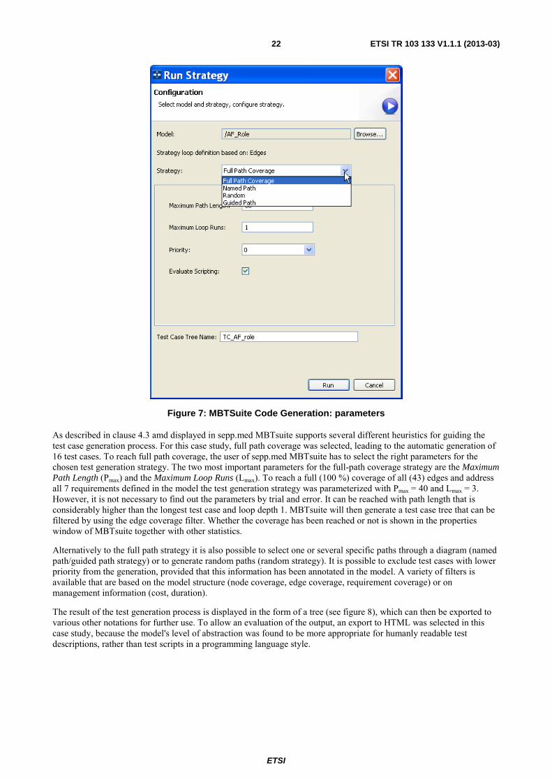
Figure 7: MBTSuite Code Generation: parameters
As described in clause 4.3 amd displayed in sepp.med MBTsuite supports several different heuristics for guiding the test case generation process. For this case study, full path coverage was selected, leading to the automatic generation of 16 test cases. To reach full path coverage, the user of sepp.med MBTsuite has to select the right parameters for the chosen test generation strategy. The two most important parameters for the full-path coverage strategy are the Maximum Path Length (Pmax) and the Maximum Loop Runs (Lmax). To reach a full (100 %) coverage of all (43) edges and address all 7 requirements defined in the model the test generation strategy was parameterized with Pmax = 40 and Lmax = 3. However, it is not necessary to find out the parameters by trial and error. It can be reached with path length that is considerably higher than the longest test case and loop depth 1. MBTsuite will then generate a test case tree that can be filtered by using the edge coverage filter. Whether the coverage has been reached or not is shown in the properties window of MBTsuite together with other statistics.
Alternatively to the full path strategy it is also possible to select one or several specific paths through a diagram (named path/guided path strategy) or to generate random paths (random strategy). It is possible to exclude test cases with lower priority from the generation, provided that this information has been annotated in the model. A variety of filters is available that are based on the model structure (node coverage, edge coverage, requirement coverage) or on management information (cost, duration).
The result of the test generation process is displayed in the form of a tree (see figure 8), which can then be exported to various other notations for further use. To allow an evaluation of the output, an export to HTML was selected in this case study, because the model's level of abstraction was found to be more appropriate for humanly readable test descriptions, rather than test scripts in a programming language style.

ETSI
ETSI TR 103 133 V1.1.1 (2013-03) 23
Figure 8: MBTSuite Code Generation: parameters

ETSI
ETSI TR 103 133 V1.1.1 (2013-03) 24
Table 4 presents a sample test case automatically generated with sepp.med MBTsuite for the ATM case study.
Table 4: Sample test case automatically generated with sepp.med MBTsuite
Step Type Step Name Step Description Expected Result Requirements passed /
failed 1 Test Step InvalidCard Insert invalid card. □ / □
2 Verification Point
ATMMessage_Card_Invalid The provided card is not accepted
TP_ATM_002: Reject invalid card
□ / □
3 Verification Point ATMMessageType
Message "Card is invalid." is displayed. The ATM renders the card.
□ / □
4 Test Step InvalidCard Insert invalid card. □ / □
5 Verification Point ATMMessage_Card_Invalid
The provided card is not accepted
TP_ATM_002: Reject invalid card □ / □
6 Verification Point ATMMessageType
Message "Card is invalid." is displayed. The ATM renders the card.
□ / □
7 Test Step ValidCard Insert valid card. □ / □ 8 Test Step ValidPin PIN is valid □ / □ 9 Test Step Request amount Request 499,0 Euro. □ / □
10 Verification Point Provide amount ATM provides 499,0. □ / □
5.4.4 Evaluation
Sepp.med MBTsuite elegantly combines graphical modelling with a powerful, but yet intuitive test case generation engine. As for any other MBT tool, the abstraction level of the test cases generated with sepp.med MBTsuite highly depends on the amount of information provided during the modelling process. However this tool tends to focus more on deriving logical test cases that would require further refinement or an adaptation to an existing testing framework to become executable. The test generation strategies supported are intuitive and produce the expected results. This predictability is an important factor for MBT tools, because testers tend to be pessimistic by nature and the more they understand the basics of the algorithms used in test generation, the higher their confidence in the MBT tool.
5.5 Applying FOKUS MDTester to case study 1 This clause describes how the FOKUS MDTester tool was used to create a model for the ATM case study.
5.5.1 Modelling case study 1 with FOKUS MD Tester
The first step in creating the model for the ATM case study consisted in identifying the situations that needed to be tested, each of which would correspond to a test purpose.
This was achieved through analysis of the problem and discussions between the experts during STF sessions. For the manually design state machine representing system behaviour, a total of 7 test purposes were identified and are listed below in table 5.
Table 5
TP_ATM_001
ID: TP_ATM_001
Summary: Valid card and valid PIN code.
Description: Check that if the user inserts a valid card, then enters a valid PIN code the ATM displays the page requesting the user to select the amount he/she wishes to withdraw.

ETSI
ETSI TR 103 133 V1.1.1 (2013-03) 25
TP_ATM_002
ID: TP_ATM_002
Summary: Reject invalid card.
Description: Check that if the user inserts a card of a type not known to the ATM, then the ATM displays an error message and rejects the card.
TP_ATM_003
ID: TP_ATM_003
Summary: Valid card and invalid PIN code.
Description: Check that if the user inserts a valid card, then enters an invalid PIN code the ATM displays an error message indicating that the PIN code is invalid and requests the user to re-enter a valid PIN code.
TP_ATM_004
ID: TP_ATM_004
Summary: Valid card and invalid PIN code repetition.
Description: Check that if the user enters an invalid PIN code 3 times the ATM displays stops the procedure and gets back to initial state.
TP_ATM_005
ID: TP_ATM_005
Summary: Accept valid card.
Description: Check that if the user inserts a valid card, the ATM displays the page requesting the user to enter a valid PIN code.
TP_ATM_006
ID: TP_ATM_006
Summary: Valid amount request.
Description: Check that if the user requests an amount within her allowed range, the ATM delivers the requested amount to the user.
TP_ATM_007
ID: TP_ATM_007
Summary: Invalid amount request.
Description: Check that if the user requests an amount exceeding her allowed range, the ATM displays an error message indicating that the requested amount is outside the allowed range.
5.5.2 FOKUS MD Tester model of case study 1
The model consists of 4 main sub models, each one addressing a specific aspect of the test project:
The TPs were modelled in the test objectives model to facilitate traceability and evaluation of the case study afterwards. Figure 9 displays a view on the test objectives model created in MDTester, out of which the tables presented in clause 5.6.1 were automatically generated for the present document.

ETSI
ETSI TR 103 133 V1.1.1 (2013-03) 26
Figure 9: Excerpt of test objectives model for the ATM case study
Based on these identified TPs, a test data model was created to represent the data types exchanged with the SUT and instances thereof for stimulating the SUT or for defining constraints on its expected responses. Figure 10 displays some examples of such data instances used by the ATM to communicate with the external world.

ETSI
ETSI TR 103 133 V1.1.1 (2013-03) 27
Figure 10: Test data model elements for ATM Case Study
Also based on the TPs, a test architecture model was created to guide the behaviour modelling process by constraining it to behaviour, that would be consistent with the architecture. An excerpt from that test architecture model is displayed in figure 11.
Figure 11: Test architecture for ATM Case Study

ETSI
ETSI TR 103 133 V1.1.1 (2013-03) 28
Finally the test behaviour could be modelled using the concept of test scenario represented as a test activity diagram. A test scenario represents the behaviour of the system from a tester's point of view in a black-box testing approach. Based on such a test scenario, a set of test cases can be generated. As depicted in figure 12 the test activity diagram distinguishes between stimuli to the system (e.g. SendDataAction) and responses expected. To represent the test behaviour for the ATM machine case study, a test activity diagram was created, comprising a total of 12 nodes and 14 edges. It should be noted that the test activity diagram includes a loop between the activity of the ATM requesting the user to enter a valid PIN and the activity of the user entering the PIN, for the case an invalid PIN was entered. Therefore, the maximal number of loops to take into account while exploring the directed graph will have to be chosen carefully to reach maximal coverage with a minimal number of test cases.
Figure 12: Test activity diagram for ATM Case Study
5.5.3 Generating test cases with FOKUS MD Tester for case study 1
The generation of test cases with FOKUS MD Tester was based on the test activity diagram displayed in figure 12. The test generation algorithm also used the data model available for this case study to generate variants of the test cases generated through exploration of the directed graph. As illustrated in the data model of the CardKindType (see figure 13), 4 different types of bank cards were defined and supported by the ATM.
Thus additionally to the generic test case obtained through path exploration, 3 more test cases are generated, each using one of the particular card types defined as acceptable by the ATM as input. Therefore, given that there are 11 possible paths derived from the one with accepted card, 33 additional test cases were generated based on this data exploration.

ETSI
ETSI TR 103 133 V1.1.1 (2013-03) 29
Figure 13: Graphical representation of model element used for modelling card type
In total 49 test cases are needed to reach full coverage of the defined test purposes. This was obtained by setting the Nl parameter to a value of 5 (see figure 14). Taking into account the 33 additional test cases generated through data flow exploration, the total number of automatically generated test cases is 16, which matches the number of test cases also obtained with the sepp.med MBTsuite tool.
Figure 14: Test case Generation with MDTester: parameters
Figure 15 displays a sample from the generated test cases, this time represented as a sequence diagram. This underlines another specificity of MDTester compared to other MBT tools, i.e. its ability not only to support graphical modelling of test scenarios for automated test case generation, but also to produce a graphical representation of the automatically generated test cases.

ETSI
ETSI TR 103 133 V1.1.1 (2013-03) 30
Figure 15: Sample test case automatically generated with MDTester for the ATM case study
5.5.4 Evaluation
The evaluation of the case study is based upon coverage of test purposes defined before creating the test model. A total of 31 test cases were generated to optimally cover the 7 predefined test purposes. Table 6 displays the list of test purposes and indicates whether they were covered by the generated test cases or not. As visible in table 6, a coverage rate of 100 % could be achieved.
Table 6: Overview of TP coverage from the ATM case study
Test Objective Covered
TP_ATM_001 X
TP_ATM_002 X
TP_ATM_003 X
TP_ATM_004 X
TP_ATM_005 X
TP_ATM_006 X
TP_ATM_007 X
To support an evaluation of the test generation process or to estimate progress of manual test design, the MDTester tool also automatically generates a traceability matrix indicating whether and how each of the individual test purposes is covered by the test cases present in the test model. The traceability matrix for this case study generated for this case study can be viewed in clause A.1.2.

ETSI
ETSI TR 103 133 V1.1.1 (2013-03) 31
6 Case study 2: ITS location services This clause describes results of modelling of Location Service functionality of GeoNetworking protocol and further test generation for it.
6.1 General description of case study 2 This clause contains general description of Location Service functionality of GeoNetworking protocol.
6.1.1 Overview of case study 2
The GeoNetworking protocol is a network layer protocol that provides packet routing in an ad hoc network. It supports communication among individual ITS stations as well as the distribution of packets in geographical areas. A GeoAdhoc unit maintain a local data structure, referred to as Location Table (LocT), where each entry holds information about other ITS stations, primarily its location data (longitude, latitude, altitude, speed, heading, etc.).
Location Service functionality of GeoNetworking protocol supports search for protocol unit with the address specified. Location Service is executed when a protocol unit receives from an upper layer a request to send some data to the specified address, for which this unit has no location data (see clause 9.2.4 [i.1]).
Location data of other protocol units are stored in internal Location Table. Location Table is maintained by processing of all the incoming packets — if an incoming packet contains newer location data for some address in, the unit updates the corresponding record in the Location Table (see clause 6.1 [i.1]).
Location Service is started when the unit does not find locally the location data for an address specified in GeoUnicast request. In this case the unit stores the data to be send to the address sought into internal Location Service buffer (specific to the address) and sends to all its neighbours a Location Service request packet (see clause 9.2.4.2.2 [i.1]). After receiving a response — in a Location Service response packet — it stores the location data for the address, puts data stored in Location Service buffer into the corresponding GeoUnicast packets, and sends the last to neighbour unit(s) according to GeoUnicast sending algorithm (see clause 9.2.4.2.4 [i.1]).
Along with sending a Location Service request the unit sets a timer, and if it expires before any response comes, the same Location Service request packet is send once more. This is repeated until the number of requests sent to find a certain address exceeds the specified maximum. In this case the unit cleans up the Location Service buffer for this address and stops the corresponding timer (see clause 9.2.4.2.3 [i.1]).
When a unit receives a Location Service request for its own address, it generates Location Service response packet and sends it as a GeoUnicast packet (see clause 9.2.4.4 [i.1]).
When a unit receives a Location Service reply packet destined for another unit, it processes the packet header and forwards it as a GeoUnicast packet. When a unit receives a Location Service request packet destined for another unit, it processes the packet header and forwards it as Topologically Scoped Broadcast (TSB) packet (see clause 9.2.4.3 [i.1]).
6.1.2 Common base for modelling of case study 2
The following the external events related with Location Service were modelled by all tools:
• Initiation of Location Service execution by GeoUnicast request having unknown target address.
• Expiration of Location Service request retransmit timer for a certain sought address.
• Income of Location Service request packet from the lower layer.
• Income of Location Service reply packet from the lower layer.
The following elements of behaviour were commonly modelled:
• Sending initial Location Service request.
• Sending repeated Location Service on retransmit timer expiration.

ETSI
ETSI TR 103 133 V1.1.1 (2013-03) 32
• Stopping Location Service for an address after exceeding retransmit counter maximum.
• Processing of Location Service request targeted to this unit, sending Location Service reply.
• Processing of Location service reply targeted to this unit.
• Forwarding Location Service request targeted to another unit.
• Forwarding LocationService reply targeted to another unit.
Some experts have modelled more wide sets of external events and more wide sets of behaviours. Approaches used for modelling of Protocol Data Units (PDUs) were different: sometimes they were modelled as separate data structures, sometimes only their abstract characteristics were modelled as event data.
6.1.3 ETSI test cases for case study 2
Test configurations, test suite structure, and test purposes proposed by ETSI for GeoNetworking protocol are presented in [i.2].
The following test configurations are defined:
• TC01: consists of IUT, ItsNodeA, and ItsNodeB. ItsNodeA is not in IUT communication range, ItsNodeB is in IUT communication range, and ItsNodeB is closer to IUT and is in direction of ItsNodeA.
• TC02: consists of IUT, ItsNodeB, and ItsNodeD. Both ItsNodeB and ItsNodeD are in IUT communication range, ItsNodeD is closer to IUT and is in direction of ItsNodeB.
• TC03: consists of IUT, ItsNodeA, ItsNodeB, and ItsNodeC. ItsNodeA is not in IUT communication range, ItsNodeB and ItsNodeC are in IUT communication range, ItsNodeB is closer to IUT and is in direction of ItsNodeA, ItsNodeC is not in direction of ItsNodeA.
• TC03: consists of IUT, ItsNodeA, ItsNodeB, ItsNodeC, and ItsNodeD. ItsNodeA is not in IUT communication range, ItsNodeB, ItsNodeC, and ItsNodeD are in IUT communication range, ItsNodeD is closer to IUT and is in direction of ItsNodeB, and ItsNodeB is in direction of ItsNodeA, ItsNodeC is not in direction of ItsNodeA.
The following test purposes are defined for GeoNetworking Location service and are used as a common base for evaluation of test cases generated:
• TP/GEONW/PON/LOS/BV/01: Test of first LS invocation for unknown Destination node.
• TP/GEONW/PON/LOS/BV/02: Test of no LS invocation for unknown Destination node when LS procedure is already active.
• TP/GEONW/PON/LOS/BV/03: Test of packet buffering into LS buffer.
• TP/GEONW/PON/LOS/BV/04: Test of LS buffer characteristics: FIFO type.
• TP/GEONW/PON/LOS/BV/05: Test of LS buffer characteristics: discarding upon LT expiration.
• TP/GEONW/PON/LOS/BV/06: Test of LS Request retransmission if no answer is received.
• TP/GEONW/PON/LOS/BV/07: Test of LS Request retransmission if no answer is received, stopping after the number of retransmissions exceed the maximum value of LS retransmit counter.
• TP/GEONW/PON/LOS/BV/08: Test of LS Reply generation by destination node.
• TP/GEONW/PON/LOS/BV/09: Test of no LS Reply generation for already answered LS Request packets.
• TP/GEONW/PON/LOS/BV/10: Test of LS Request forwarding.
• TP/GEONW/PON/LOS/BV/11: Test of LS Reply forwarding.

ETSI
ETSI TR 103 133 V1.1.1 (2013-03) 33
• TP/GEONW/PON/LOS/BV/12: Test flushing of the LS buffer, initiated by the processing of a common header from the target destination.
Sometimes additional test purposes are used for evaluation of tests targeted on other behaviour.
ETSI has developed an abstract test suite for GeoNetworking protocol in TTCN-3. In the test suite developed each of the test purposes presented above has the single corresponding test case.
6.2 Applying Microsoft® Spec Explorer to case study 2 This clause describes modelling of Location Service functionality of GeoNetworking protocol and further test generation for this function with the help of Microsofft Spec Explorer.
6.2.1 Modelling case study 2 with Spec Explorer
Location Service functionality of GeoNetworking protocol supports search for protocol unit with the address specified. Location Service is executed when a protocol unit receives from an upper layer a request to send some data to the specified address, for which this unit has no location data (see clause 9.2.4 [i.1]).
Location data of other protocol units are stored in an internal Location Table, which stores for each unit an address with location data (longitude, latitude, altitude, speed, heading, etc.). The Location Table is maintained by processing of all the incoming packets — if the unit notes newer location data for some address in an incoming packet, it updates the corresponding record in the Location Table (see clause 7.1 [i.1]).
Location Service is started when the unit does not find the location data for an address specified in GeoUnicast request. In this case the unit stores the data to be sent to the address sought into internal Location Service buffer (specific to the address) and sends to all its neighbours a special Location Service request packet (see clause 9.2.4.2.2 [i.1]). After receiving a response — in a special Location Service response packet — it stores the location data for the address, turns data stored in Location Service buffer into the corresponding GeoUnicast packets, and sends them to some neighbour unit(s) according to GeoUnicast sending algorithm (see clause 9.2.4.2.4 [i.1]).
Along with sending a Location Service request the unit sets a timer, and if it expires before any response comes, the same Location Service request packet is send once more. This is repeated until the number of request send to find the certain address exceeds the specified maximum. In this case the unit cleans up the Location Service buffer for this address and stops the corresponding timer (see clause 9.2.4.2.3 [i.1]).
When a unit receives a Location Service request for its own address, it generates Location Service response packet and sends it as a GeoUnicast packet (see clause 9.2.4.4 [i.1]).
When a unit receives a Location Service reply packet destined for another unit, it processes the packet header and forwards it as a GeoUnicast packet. When a unit receives a Location Service request packet destined for another unit, it processes the packet header and forwards it as Topologically Scoped Broadcast (TSB) packet (see clause 9.2.4.3 [i.1]).
The modelling process used is based on the following decisions:
• The source of information for modelling is twofold — the requirements of the GeoNetworking standard, Media-Independent functionality [i.1], and communication with ETSI experts on [i.1] in cases where the text of the standard in unclear, incomplete, or inconsistent.
• The functionality of GeoNetworking Location Service is modelled completely, including all procedures and algorithms from referenced other parts of the standard (with two exceptions: contention-based forwarding algorithm for sending UniCast packets — only greedy algorithm is modelled (see annex C [i.1]), — and distance calculation procedure — it is simplified to a procedure taking into account only altitude and longitude) and all internal data structures it relies on.
• The developed model is a generic executable model of the specified part of protocol functionality; it does not include only a subset of possible protocol operation scenarios, but describes its complete behaviour.
ETSI
ETSI TR 103 133 V1.1.1 (2013-03) 34
• The other functionality was modelled only in parts having direct relation to Location Service. For example, the only interface with upper layer that has relation with Location Service is possibility to send a GeoUnicast packet. The contents of this packet and other data that can be specified in the request, like packet lifetime or repetition interval (see annex H.2 [i.1]) have no direct relation to Location Service operation, and so are not taken into consideration during modelling. However, packet structure (see clause 8 [i.1]) was modelled completely, although not all the fields of GeoNetworking packets have relation to Location Service operation. This is done because packets as model data types were described at the beginning of modelling when the importance of their various parts for the target functionality was not clear. This patterns is used in all cases where it was not clear whether the part of data structure or behaviour has the relation to Location Service — such parts of the protocol were modelled to make possible further analysis of their influence and to escape preliminary and not argumented removal of important details from the model.
• Since Location Service bears on a significant part of protocol functionality and internal data structures, the complexity of the developed model is rather high. Like any piece of software of significant complexity, the model developed has very high chances to contain errors, which should be removed before test generation. Two techniques are used to detect the errors: model reviews and model simulation on a set of simple scenarios (that can be called model unit testing). Both approaches help to find a lot of errors, and while the first technique is less expensive, it could not provide the same results being used alone.
The following decisions are made concerning the general structure of the model:
• The model is synchronous, that is it operates by processing external events and providing outputs on them without parallel processing of several events. Each event is processed separately, and output generated may include several packets sent in two different ways — packets sent directly to specific lower layer protocol unit or packets broadcasted on the lower layer. Synchronous modelling is possible due to the structure of GeoNetworking protocol itself — its operation can be represented in synchronous way, although implementations can work asynchronously.
• The model interface includes all the external events that have relation with Location Service:
- GeoUnicast request having payload and target address as parameters. Other parameters specified in the protocol standard are skipped as irrelevant.
- Income of Location Service request packet from the lower layer.
- Income of Location Service reply packet from the lower layer.
- Expiration of Location Service request retransmit timer for a certain sought address.
- Expiration of lifetime of a packet stored in Location Service buffer for a certain address. This event has as parameters the sought address and the position of expired packet in the buffer.
- Expiration of lifetime of a record in Location Table for a certain address.
The last three events are related with timer expirations. Their representation as external events independent from protocol unit operation has great advantages — possibility to omit modelling of timings, which is rather hard, and possibility to simulate easily very specific and rare situations — but also has a drawback — the complexity of adaptation of tests created on the base of the model. Such an adaptation requires very accurate arrangement of test sequence events and data of some operations or complete control over the clock of the implementation of protocol unit.
• The modular structure of the model is implemented as much as possible similar to the structure of the standard requirements — where the standard text refers to some other part of it, the corresponding procedure is implemented in the model and called. So, where several places refer to the same single part of text, the corresponding model parts call the corresponding single procedure. However, in some cases behaviour described in different parts of the standard is implemented in one place in the model. These cases are processing of incoming Location Service requests and replies, which are described in the standard separately for forwarding unit and for destination unit, but appear to be almost the same, except for final two or three steps of processing (see clauses 9.2.4.2.4, 9.2.4.3 and 9.2.4.4 [i.1]).

ETSI
ETSI TR 103 133 V1.1.1 (2013-03) 35
• From the other side, the model is developed as a single unit processing all kinds of external events, although there is a possibility to model the same behaviour by several communicating units, each processing only specific subset of external events. This approach is taken because the functionality of GeoNetworking protocol was unfamiliar to modeller at the beginning of modelling, so the second way seemed to be more error-prone. With good understanding of protocol behaviour and detailed functionality the second approach may be more attractive. It results in simpler model units with less functions clearly separated from each other.
• Another decision concerns modelling of communications between different protocol units. The tool makes possible two approaches: to model behaviour of a single unit and to model its communication with other units as external events, or to model several protocol units and to model their communication as generation of an event by one of them and its consumption by another one. The first way is chosen in this case study, because the second one does not make the modelling simpler (each protocol unit is an instance of the model class, which is the same as in the first case), but makes more complex the dynamic system state (a combination of states of all units involved), which may be an obstacle for effective test generation.
6.2.2 Spec Explorer model of case study 2
The Spec Explorer model of GeoNetworking Location Service functionality consists from the following parts, all written in C#:
• Common types module (the file GNType.cs forming a separate project in the Visual Studio® solution), containing definition of all the data types used in external events. These definitions are made separate because they are used both in the model and in the abstract description of implementation interface needed for test generation. In addition this module contains test data pools for various data used in tests — GeoNetworking packets, addresses, location data, etc. The complete list of data types defined in this module is the following:
- Enumerations:
� GNStationType enumeration representing possible values of station type bit of the protocol packet common header (see clause 8.5.2 [i.1]);
� EmbeddedPacketType enumeration representing possible values of Next Header (NH) field of the protocol packet common header (see clause 8.5.2 [i.1]);
� HeaderType enumeration representing possible values of Header type (HT) and HeaderSubType (HST) fields of the protocol packet common header (see clause 8.5.2 [i.1]);
� GUCForwardingAlgorithm enumeration representing possible options for forwarding algorithm used in GeoUnicast (see annex C [i.1]).
- Protocol packet data structures:
� LLAddress representing lower layer address (see clause 6.3 [i.1]);
� GNAddress representing GeoNetworking address (see clause 6 [i.1]);
� MinPositionData, AddPositionData, and AreaInfo representing possible structures of location data stored internally or sent in various types of packets (see clause 8.4.2.2 [i.1]);
� ShortPositionVector reprenting protocol Short Position Vector data structure (contains only address and minimum position data) (see clause 8.4.3 [i.1]);
� LongPositionVector reprenting protocol Long Position Vector data structure (contains address, minimum position data, and additional position data) (see clause 8.4.2 [i.1]);
� CommonGNPHeader reprenting protocol packet common header structure (see clause 8.5 [i.1]);
� GNPacket representing protocol packet structure (see clause 8.6 [i.1]). Several possible packet structures are mixed, so that one data type can be used for all types of packets.
ETSI
ETSI TR 103 133 V1.1.1 (2013-03) 36
- Auxiliary structures for representing model interfaces:
� SentPacket representing GeoNetworking packet sent to specific lower layer address;
� FullResult representing two lists of packets sent by a protocol unit through different interfaces-directly to some lower layer address or by lower layer broadcast — in response for some external event.
- Test data pools:
� PositionDataPool contains definition and initialization of several position data instances;
� GNAddressPool contains definition and initialization of several GeoNetworking addresses;
� GNPacketPool contains definition and initialization of several packet instances, actually, several Location Service requests and several Location Service replies.
• The main model module (the file GNUnitModel.cs) containing the following items:
- Data structure types for internal protocol unit data:
� LocalPositionVector representing unit position data (see clause 7.2 [i.1]). Here the same fields are used as in LongPositionVector, except for an address. This is done according to the clarifications made by standard's authors, not to the standard text, which is not consistent with some other parts.
� LocationTableRecord representing position data stored for an address (see clause 7.1 [i.1]). Here the same fields are used as in LongPositionVector, except for an address. This is done according to the clarifications made by standard's authors, not to the standard text, which is not consistent with some other parts.
� PacketBuffer representing internal storage for deferred packets, the single class for unicast buffer for certain address and for broadcast buffer (see clause 7.5 [i.1]).
� SDUBuffer representing a buffer for higher layer packets, Location Service buffer for a certain address is an instance of such a buffer (see clause 7.4 [i.1]).
- Protocol unit behaviour model — GeoNetworkingUnitModel class — modelling the single protocol unit (so all its data fields and methods are static) and having the following elements.
� Data fields:
� locationTable representing location data table for known addresses (see clause 7.1 [i.1]). Implemented as a map of addresses to Location Table records;
� localAddress representing an address of this unit;
� localPositionVector representing position data of this unit (see clause 7.2 [i.1]);
� seqNumber of unsigned short type representing the local sequence number for counting outgoing packets (see clause 7.3 [i.1]);
� lsBuffer representing Location Service buffer (see clause 7.4 [i.1]). Implemented as a map of addresses to SDUBuffers;
� ucBuffer representing unicast packet buffer (see clause 7.5 [i.1]). Implemented as a map of addresses to PaketBuffers;
� bcBuffer representing broadcast packet buffer (see clause 7.5 [i.1]);
� lsTimers representing Location Service retransmit timers (see clause 9.2.4.2.3 [i.1]). Implemented as a map of addresses to boolean flags saying whether the corresponding timer is set;
� lsRetCounters representing Location Service retransmit counters (see clause 9.2.4.2.3 [i.1]). Implemented as a map of addresses to integer values of the corresponding counters;

ETSI
ETSI TR 103 133 V1.1.1 (2013-03) 37
� lsRequestCash representing storage of already created Location Service requests to be send several times on expiration of retransmit timers. Implemented as a map of addresses to GNpackets;
� Auxiliary operations:
• Static constructor initializes maximum size of broadcast buffer and local position data;
• Ushort GetSequenceNumber() returns the local sequence number and increments it;
• LocationTableRecord InitLocaTableRecord(GNAddress addr) implements initialization of a Location Table record for the given address;
• Bool SendAsTSB(GNPacket packet) implements a procedure described in (see clause 9.3.5.2 [i.1]) — sending a packet with Topologically Scoped Broadcasting. Returns true if the packet can be actually sent, and false if it cannot be sent, but stored in broadcast buffer instead;
• GNPacket CreateLSRequest(GNAddress addr) implements a procedure of creating a Location Service request packet for the given address (see clause 9.2.4.2.2 [i.1]);
• GNPacket CreateLSReply(LongPositionVector lpv) implements a procedure of creating a Location Service reply packet for the unit with the given position data (see clause 9.2.4.4 [i.1]);
• GNPacket CreateGeoUnicastPacket(string s, GNAddress addr) implements a procedure for creating a GeoUnicast packet with the given payload for the given address (see clause 9.3.4.2 [i.1]);
• Bool ProcessCommonHeader(GNPacket packet) implements a procedure of common header processing (see clause 9.3.3 [i.1]). Returns true if the packet should be processed further and false if it should be skipped;
• Bool NonDuplicatePacket(GNPacket packet) implement a procedure of duplicate packet detection (see annex A [i.1]). Returns true if the packet is new and false if it is a duplicate;
• GNPacket UpdateHeader(GNPacket packet) implements a procedure of updating the header fields of the given packet before forwarding it further (see clauses 9.3.5.3 and 9.3.4.3 [i.1]);
• Int Distance(LocalPositionVector x, ShortPositionVector y) implements distance calculation between the units with the given position data;
• LLAddress DetermineLLAddress(ShortPositionVector spv) implements a procedure calculating the lower layer unit to forward a packet, destined to the given position, to according to the greedy algorithm (see annex C.2 [i.1]).
� Model operations corresponding to operations of the interface under test:
• GNPacket GeoUnicast(string payload, GNAddress addr) models processing a GeoUnicast request from the upper layer for the given payload and address. Only the part related with Location Service operation is implemented. If Location Service is not triggered, GeoUnicast packet is returned without any processing required in (see clause 9.3.4.2 [i.1]);
• FullResult LSRequestReceived(GNPacket packet) models processing of a Location Service request;
• FullResult LSReplyReceived(GNPacket packet) models processing of a Location Service reply;
• GNPacket LSTimer(GNAddress addr) models processing of expiration of Location Service retransmit timer for the given address;

ETSI
ETSI TR 103 133 V1.1.1 (2013-03) 38
• Void LSBufferedPacketExpires(int index, GNAddress addr) models processing of lifetime expiration of a packet stored in Location Service buffer. The second parameter specifies an address, for which theу expired packet should be sent, the first one — the position of the expired packet in the buffer;
• Void LTRecordExpires(GNAddress addr) models processing of lifetime expiration of Location Table record for the given address.
- Runner class implementing several operation scenarios for model simulation and testing.
The complete model is presented in the annex.
6.2.3 Generating test cases with Spec Explorer for case study 2
Due to the complexity of the model developed straightforward test generation for it is impossible — the tool generates some set of tests, which are all consist of single transition and can hardly be distinguished from each other.
To provide relevant tests one needs to take some test adequacy or test coverage criterion as a base. Spec Explorer has no coverage criterion as a parameter of test generation, but it supports model slicing — a technique that selects a specific set of behaviour scenarios from the model (with the help of their description in CordScript language, somehow extending regular expressions) and targets test generation to produce tests that correspond to this set of scenarios.
So, one still need some coverage criterion to select a relevant set of scenarios from a model.
The coverage of specific statements of standard requirements is taken as a target test coverage criterion in this case study. To select the relevant set of requirements the standard text [i.1] related with Location Service functionality and processing of the chosen interface events (see clause 6.2.1) is analysed and the statements presented in table 7 are selected. The following shortenings are used in the second column of table7:
• "GU request" means GeoUnicast request.
• "LS request" means income of Location Service request packet.
• "LS reply" means income of Location Service reply packet.
• "LS timer expiration" means expiration of Location Service request retransmit timer.
• "Packet expiration" means expiration of lifetime of a packet stored in Location Service buffer.
• "LT record expiration" means expiration of lifetime of a record in Location Table.

ETSI
ETSI TR 103 133 V1.1.1 (2013-03) 39
Table 7
N Related interface
event
Position in the standard text
[i.1]
Requirement statement Notes
1 GU request [i.1] 9.3.4.2, item 1
Check whether it has a valid position vector for DE in its LocT. If no valid position vector information is available, the source shall invoke the location service as specified in clause 9.2.4 and omit the execution of further steps.
Location Service invocation is described in clause 9.2.4.2.2, rows 2-6 [i.1].
2 GU request [i.1] 9.2.4.2.2, item 1
Check whether a LS for the sought GN_ADDR is in progress, i.e. the flag LS_pending is set TRUE. If LS_pending is TRUE for the sought GN_ADDR, the packet shall be buffered in the LS packet buffer (see clause 7.4) and the execution of the next steps shall be omitted.
LS buffer is described in clause 7.4.2, rows 33-34 [i.1].
3 GU request 9.2.4.2.2, item 2 Issue a LS Request packet with a format as specified in clause 8.6.7 as a TSB packet. Set the fields of the Common Header to the values specified in table 18; Set the fields of the LS Request Extended Header to the values specified in table 19.
Sending TSB packet is described in clause 9.3.5.2, rows 64-65 [i.1].
4 GU request 9.2.4.2.2, item 3 Start a timer TLS, GN_ADDR with a timeout set to the value of the MIB attribute itsGnLocationServiceRetransmitTimer.
5 GU request 9.2.4.2.2, item 4 Initialize the LS retransmit counter for the GeoAdhoc router GN_ADDR RTCLS, GN_ADDR to 0.
6 GU request 9.2.4.2.2, item 5 Add a LocTE for the sought GN_ADDR in its LocT and sets the flag LS_pending to TRUE.
7 LS timer expiration
9.2.4.2.3, item 1 If the timer TLS, GN_ADDR for the GN_ADDR expires, the source shall execute the following operation: Check the retransmit counter RTCLS, GN_ADDR.
8 LS timer expiration
9.2.4.2.3, item 2 If the retransmit counter is less than the maximum number of LS retransmissions set by the MIB attribute itsGnLocationServiceMaxRetrans, i.e. RTCLS, GN_ADDR < itsGnLocationServiceMaxRetrans the GeoAdhoc router shall:
9 LS timer expiration
9.2.4.2.3, item 2.a
Re- issue a LS Request packet with the format as specified in clause 8.6.7 as a TSB packet.
Sending TSB packet is described in clause 9.3.5.2, rows 64-65 [i.1].
10 LS timer expiration
9.2.4.2.3, item 2.b
Restart the timer TLS, GN_ADDR with a timeout set to of itsGnLocationServiceRetransmitTimer.
11 LS timer expiration
9.2.4.2.3, item 2.c
Increment the retransmit counter RTCLS, GN_ADDR.
12 LS timer expiration
9.2.4.2.3, item 3 If the retransmit counter is greater equal than the maximum number of LS retransmissions set by the MIB attribute itsGnLocationServiceMaxRetrans, i.e. RTCLS, GN_ADDR ≥ itsGnLocationServiceMaxRetrans the GeoAdhoc router shall.
13 LS timer expiration
9.2.4.2.3, item 3.a
Flush the LS packet buffer (see clause 7.4) for the sought GN_ADDR and discard the stored packets.
LS buffer is described in clause 7.4.2, row 37 [i.1].
14 LS timer expiration
9.2.4.2.3, item 3.b
Remove the LocTE for the sought GN_ADDR.
15 LS reply 9.2.4.2.4, item 1 If the source receives a LS Reply packet for the sought GN_ADDR, the source shall execute the following operations: Common Header processing (see clause 9.3.3).
Common Header processing is described in clause 9.3.3, rows 41-47 [i.1].
16 LS reply 9.2.4.2.4, item 2 Execute duplicate packet detection (see annex A); if the LS Reply packet is a duplicate, discard the packet and omit the execution of further steps.
Duplicate packet detection is described in annex A, row 73 [i.1].
17 LS reply 9.2.4.2.4, item 3 Update the SO PVLocT with the SO PV of the received LS Reply Extended Header using the algorithm specified in clause B.2.
LocT PV update is described in annex B.2, row 74 [i.1].
18 LS reply 9.2.4.2.4, item 4 Set the SO IS_NEIGHBOUR flag to FALSE, if the SO GN_ADDR does not equal the SE GN_ADDR.

ETSI
ETSI TR 103 133 V1.1.1 (2013-03) 40
N Related interface
event
Position in the standard text
[i.1]
Requirement statement Notes
19 LS reply 9.2.4.2.4, item 5.a
If SO LS_pending is TRUE: flush the SO LS packet buffer (see clause 7.4); forward the stored packets; set SO LS_pending to false.
LS buffer is described in clause 7.4.2, row 35 [i.1].
20 LS reply 9.2.4.2.4, item 5.b
If the UC forwarding packet buffer (see clause 7.5) for SO is not empty, flush the UC forwarding buffer and forward the stored packets.
UC buffer is described in (see clause 7.5.3, row 40 [i.1]).
21 LS reply 9.2.4.2.4, item 6 Flush the LS packet buffer (see clause 7.4) for the sought GN_ADDR and forward the stored packets.
LS buffer is described in clause 7.4.2, row 35 [i.1].
22 LS reply 9.2.4.2.4, item 7 Set the flag LS_pending for the sought GN_ADDR to false. 23 LS reply 9.2.4.2.4, item 8 Stop the timer TLS, GN_ADDR. 24 LS reply 9.2.4.2.4, item 9 Reset the re-transmit counter RTCLS, GN_ADDR. 25 LS request 9.2.4.3,
paragraph 1 If a GeoAdhoc router receives a LS Request packet and the Request GN_ADDR field in the LS Request header does not match its GN_ADDR, the GeoAdhoc router shall handle the packet according to the packet handling procedure for TSB (see clause 9.3.5.3), except step 7 for passing the payload of the GN-PDU to the upper protocol entity.
Forwarding TSB packets is described in clause 9.3.5.3, see rows 66-72 [i.1]. Step 7 here is mentioned by mistake, step 5 is meant.
26 LS reply 9.2.4.3, paragraph 2
If a GeoAdhoc router receives a LS Reply packet and the GN_ADDR in the DE PV of the LS Reply packet does not match its GN_ADDR, the GeoAdhoc router shall handle the packet according to the packet handling operations for GeoUnicast (see clause 9.3.4).
Forwarding GeoUnicast packets is described in clause 9.3.4.3, rows 48-63 [i.1].
27 LS request 9.2.4.4, item 1 On reception of a LS Request packet, the GeoAdhoc router shall check the Request GN_ADDR field. If this MID field matches the MID field of its GN_ADDR, the GeoAdhoc router shall execute the following operations: Common Header processing (see clause 9.3.3).
Common Header processing is described in clause 9.3.3, rows 41-47 [i.1].
28 LS request 9.2.4.4, item 2 Execute duplicate packet detection (see annex A); if the LS Request packet is a duplicate, discard the packet and omit the execution of further steps.
Duplicate packet detection is described in annex A, row 73 [i.1].
29 LS request 9.2.4.4, item 3 Update the SO PVLocT with the SO PV fields of the LS Request Extended Header using the algorithm specified in clause B.2.
LocT PV update is described in annex B.2, row 74 [i.1].
30 LS request 9.2.4.4, item 4 Set the SO IS_NEIGHBOUR flag to FALSE if SO GN_ADDR does not equal the SE GN_ADDR.
31 LS request 9.2.4.4, item 5 Issue a LS Reply packet as a GeoUnicast packet (see clause 8.6.2) and forward the packet according to the forwarding procedure for GeoUnicast (see clause 9.3.4).
Forwarding GeoUnicast packets is described in clause 9.3.4.3, rows 48-63 [i.1].
32 LT record expiration
7.1.3 The entries in the Location Table shall be soft-state, i.e. entries are added with a lifetime T(LocTE) set to the value of the MIB attribute itsGnLifetimeLocTE and shall be removed when the lifetimes expires.
33 GU request 7.4.2, item 1 GeoNetworking packets arriving at the LS packet buffer for a destination (GN_ADDR of a certain ITS station) shall be queued at the tail of the queue.
34 GU request 7.4.2, item 2 When a new GeoNetworking packet arrives at the LS packet buffer and exceeds the buffer capacity (buffer overflow), GeoNetworking packets from the head of the queue are removed and the new GeoNetworking packet queued at the tail (head drop).
35 LS request, LS reply
7.4.2, item 3 When the LS is completed, the LS packet buffer shall be flushed, i.e. all GeoNetworking packets stored in the buffer shall be sent in a First-In-First-Out (FIFO) manner.

ETSI
ETSI TR 103 133 V1.1.1 (2013-03) 41
N Related interface
event
Position in the standard text
[i.1]
Requirement statement Notes
36 Packet expiration
7.4.2, item 4 When the queuing time of the GeoNetworking packet in the LS packet buffer exceeds the packet lifetime carried in the GeoNetworking packet's LT field in the Extended Header, the GeoNetworking packet shall be discarded.
37 LS timer expiration
7.4.2, item 6 When the LS does not complete, all stored GeoNetworking packets shall be discarded triggered by the LS.
38 GU request, LS timer
expiration, LS reply
7.5.3, item 1 GeoNetworking packets arriving at the forwarding packet buffer shall be queued at the tail of the queue.
39 GU request, LS timer
expiration, LS reply
7.5.3, item 2 When a new GeoNetworking packet arrives at the forwarding packet buffer and exceeds the buffer capacity, GeoNetworking packets from the head of the queue are removed and the new GeoNetworking packet queued at the tail (head drop).
40 LS request, LS reply
7.5.3, item 3 When the forwarding packet buffer is flushed, the GeoNetworking packets stored in the buffer shall be forwarded in a FIFO manner.
41 LS request, LS reply
9.3.3, item 1 When a GeoAdhoc router (forwarder, receiver, destination) processes a Common Header upon reception of a GeoNetworking packet, the GeoAdhoc router shall execute the following operations: update the PV in the SE LocTE with the SE PV fields of the Common Header (see clause B.2).
LocT PV update is described in annex B.2, row 74 [i.1].
42 LS request, LS reply
9.3.3, item 2 Set the IS_NEIGHBOUR flag of the SE LocTE to TRUE.
43 LS request, LS reply
9.3.3, item 3.a If SE LS_pending is TRUE: flush the SE LS packet buffer (see clause 7.4); forward the stored packets; set SE LS_pending to false.
LS packet buffer flushing is described in clause 7.4.2, row 35 [i.1].
44 LS request, LS reply
9.3.3, item 3.b If the UC forwarding packet buffer (see clause 7.5) for SE is not empty, flush the UC forwarding buffer and forward the stored packets.
UC buffer is decribed in clause 7.5.3, row 40 [i.1].
45 LS request, LS reply
9.3.3, item 3.c If the BC forwarding packet buffer (see clause 7.5) is not empty, flush the BC forwarding buffer and forward packets.
BC buffer is described in clause 7.5.3, row 40 [i.1].
46 LS request, LS reply
9.3.3, item 4 Check the NH field of the Common Header: if NH = 0 (ANY) discard the packet and omit the execution of further steps.
Since LS request and reply packets has NH field equal to 0 in clause 8.5.3 [i.1], this item should be skipped when processing them, unless all such packets will be ignored.
47 LS request, LS reply
9.3.3, item 5 Check the HT field of the Common Header: if HT = 0 (ANY) discard the packet and omit the execution of further steps.
48 LS request, LS reply
9.3.4.3, item 1 On reception of a GeoUnicast packet, the GeoAdhoc router shall check the GN_ADDR field in the DE PV of the GeoUnicast packet header. If this address does not match its GN_ADDR, the GeoAdhoc router shall execute the following operations: Common Header processing (see clause 9.3.3).
Common Header processing is described in clause 9.3.3, rows 41-47 [i.1].
49 LS request, LS reply
9.3.4.3, item 2 Execute duplicate packet detection (see annex A); if the GeoUnicast packet is a duplicate, discard the packet and omit the execution of further steps.
Duplicate packet detection is described in annex A, row 73 [i.1].

ETSI
ETSI TR 103 133 V1.1.1 (2013-03) 42
N Related interface
event
Position in the standard text
[i.1]
Requirement statement Notes
50 LS request, LS reply
9.3.4.3, item 3 Update the PV(SO) in the LocT with the SO PV fields of the GeoUnicast Extended Header (see clause B.2).
LocT PV update is described in annex B.2, row 74 [i.1].
51 LS request, LS reply
9.3.4.3, item 4 Set the IS_NEIGHBOUR(SO) flag to FALSE if SO GN_ADDR does not equal SE GN_ADDR.
52 LS request, LS reply
9.3.4.3, item 5.a If LS_pending(SO) is TRUE flush the SO LS packet buffer (see clause 7.4); forward the stored packets; set LS_pending(SO) to false.
LS packet buffer flushing is described in clause 7.4.2, row 35 [i.1].
53 LS request, LS reply
9.3.4.3, item 5.b If the UC forwarding packet buffer (see clause 7.5) for SO is not empty, flush the UC forwarding buffer and forward the stored packets.
UC buffer is described in clause 7.5.3, row 40 [i.1].
54 LS request, LS reply
9.3.4.3, item 6 Update the DE PV(DE) in the LocT with DE PV fields in the GeoUnicast Extended Header (see clause B.2).
LocT PV update is described in annex B.2 row 74 [i.1].
55 LS request, LS reply
9.3.4.3, item 7 Update the fields of the Common Header, i.e.: the HL field with the decremented HL value; the SE PV fields with the LPV (see clause 7.2).
Here double decrement of HL field is mentioned by mistake.
56 LS request, LS reply
9.3.4.3, item 8 Update the DE PV fields with the PV(DE) in the LocT (see clause B.3).
Packet PV update is described in annex B.3, row 75 [i.1].
57 LS request, LS reply
9.3.4.3, item 9 Decrement the value of the HL field by one; if HL is decremented to zero, discard the GN-PDU and omit the execution of further steps.
58 LS request, LS reply
9.3.4.3, item 10 Determine the link-layer address LL_ADDR_NH of the next hop (see annex C).
59 LS request, LS reply
9.3.4.3, item 10.a If the MIB attribute itsGnGeoUnicastForwardingAlgorithm is set to 0 (UNSPECIFIED), execute the GF algorithm as specified in clause C.2.
Greedy forwarding is described in annex C.2, row 76 [i.1].
60 LS request, LS reply
9.3.4.3, item 10.b If the MIB attribute itsGnGeoUnicastForwardingAlgorithm is set to 1 (GREEDY), execute the GF algorithm as specified in clause C.2.
Greedy forwarding is described in annex C.2, row 76 [i.1].
61 LS request, LS reply
9.3.4.3, item 10.c If the MIB attribute itsGnGeoUnicastForwardingAlgorithm is set to 2 (CBF), execute the CBF algorithm as specified in clause C.3.
Contention-based forwarding is described in annex C.3 [i.1].
62 LS request, LS reply
9.3.4.3, item 11 If LL_ADDR_NH = 0, then buffer the GeoUnicast packet in the UC forwarding packet buffer and omit the execution of further steps.
UC buffer is described in clause 7.5.2, rows 38-39 [i.1].
63 LS request, LS reply
9.3.4.3, item 12 Pass the GN-PDU to the LL protocol entity via the IN interface and set the destination address to the LL address of the next hop LL_ADDR_NH.
64 GU request, LS timer
expiration
9.3.5.2, item 2 If no neighbour exists, i.e. the LocT does not contain a LocTE with the IS_NEIGHBOUR flag set to TRUE, then buffer the TSB packet in the BC forwarding packet buffer and omit the execution of further steps.
BC buffer is described in clause 7.5.2, rows 38-39 [i.1].
65 GU request, LS timer
expiration
9.3.5.2, item 5 Pass the GN-PDU to the LL protocol entity via the IN interface and set the destination address to the Broadcast address of the LL entity.
66 LS request 9.3.5.3, item 1 On reception of a TSB packet, GeoAdhoc router shall execute the following operations: Common Header processing (see clause 9.3.3).
Common Header processing is described in clause 9.3.3, rows 41-47 [i.1].

ETSI
ETSI TR 103 133 V1.1.1 (2013-03) 43
N Related interface
event
Position in the standard text
[i.1]
Requirement statement Notes
67 LS request 9.3.5.3, item 2 Execute duplicate packet detection (see annex A); if the TSB packet is a duplicate, discard the packet and omit the execution of further steps.
Duplicate packet detection is described in annex A, row 73 [i.1].
68 LS request 9.3.5.3, item 3 Update the PV(SO) in the LocT with the SO PV fields of the TSB Extended Header (see clause B.2).
LocT PV update is described in annex B.2, row 74 [i.1].
69 LS request 9.3.5.3, item 4 Set the IS_NEIGHBOUR(SO) flag to FALSE if SO GN_ADDR does not equal SE GN_ADDR.
70 LS request 9.3.5.3, item 6 Decrement the value of the HL field by one; if HL is decremented to zero, discard the GN-PDU and omit the execution of following operations.
71 LS request 9.3.5.3, item 7 Update the fields of the Common Header, i.e.: the HL field with the decremented HL value; the SE PV fields with the LPV (see clause 7.2).
Here double decrement of HL field is mentioned by mistake.
72 LS request 9.3.5.3, item 8 Pass the GN-PDU to the LL protocol entity via the IN interface and set the destination address to the Broadcast address of the LL entity.
73 LS request, LS reply
Annex A P is the received GeoNetworking packet; SN(P) is the sequence number in the received GeoNetworking packet; SNSO,SAV is the last received sequence number from source SO saved by the local GeoAdhoc router; SN_MAX is the maximum sequence number = 2^16-1. IF (((SN(P) > SNSO,SAV) AND ((SN(P) - SNSO,SAV) <= SN_MAX/2)) OR ((SNSO,SAV > SN(P)) AND ((SNSO,SAV - SN(P)) > SN_MAX/2))) THEN SN(P) is greater than SNSO,SAV P is not a duplicate packet SNSO,SAV ← SN(P) ELSE SN(P) is not greater than SNSO,SAV P is a duplicate ENDIF
74 LS request, LS reply
Annex B.2 RP is the received GeoNetworking packet; PVRP is the position vector in the received GeoNetworking packet; PVLocT is the position vector in the LocT to be updated; TSTPV,RP is the timestamp for the position vector in the received GeoNetworking packet; TSTPV,LocT is the timestamp for the position vector in the Location Table to be updated; TSMax is the maximum value of the timestamp = 2^32-1; T(LocTE) is the lifetime of the Location Table entry; itsGnLifetimeLocTE is the value of the MIB attribute itsGnLifetimeLocTE. IF (((TSTPV,RP > TSTPV,LocT) AND ((TSTPV,RP - TSTPV,LocT) <= TSTMax/2)) OR ((TSTPV,LocT > TSTPV,RP) AND ((TSTPV,LocT - TSTPV,RP) > TSTMax/2))) THEN TSTPV,RP is greater than TSTPV,LocT
PVLocT ← PVRP
T(LocTE) ← value(itsGnLifetimeLocTE) ELSE TSTPV,RP is not greater than TSTPV,LocT
ENDIF

ETSI
ETSI TR 103 133 V1.1.1 (2013-03) 44
N Related interface
event
Position in the standard text
[i.1]
Requirement statement Notes
75 LS request, LS reply
Annex B.3 FP is the GeoNetworking packet to be forwarded; PVFP is the position vector in the GeoNetworking packet to be forwarded; PVLocT is the position vector in the LocT; TSTPV,FP is the timestamp for the position vector in the GeoNetworking packet to be forwarded; TSTPV,LocT is the timestamp for the position vector in the Location Table; TSMax is the maximum value of the timestamp = 2^32-1 IF (((TSTPV,LocT > TSTPV,FP) AND ((TSTPV,LocT - TSTPV,FP) <= TSTMax/2)) OR ((TSTPV,FP > TSTPV,LocT) AND ((TSTPV,FP - TSTPV,LocT) > TSTMax/2))) THEN TSTPV,LocT is greater than TSTPV,FP
PVFP ← PVLocT
ELSE TSTPV,FP is not greater than TSTPV,LocT ENDIF
76 LS request, LS reply
Annex C.2 P is the GeoUnicast packet to be forwarded; i is the i-th LocTE; NH is the LocTE idenfified as next hop; NH_LL_ADDR is the link layer address of the next hop; LPV is the local position vector; PVP is the destination position vector in the GeoNetworking packet to be forwarded; PVi is the position vector of the i-th LocTE. MFR = DIST(PVP, LPV) FOR (i∈LocT) IF (i.IS_NEIGHBOUR) THEN IF (DIST(PVP, PVi) < MFR) THEN NH ← i MFR ← DIST(PVP, PVi) ENDIF ENDIF ENDFOR IF (MFR < DIST(PVP, PVLPV)) THEN SET NH_LL_ADDR = NH.LL_ADDR ELSEIF LOCAL OPTIMUM SET NH_LL_ADDR = 0 ENDIF
Only a few of the requirements statements presented in table 7 are essential for a coverage measuring — for example, each GeoUnicast request with unknown address covers rows 2-5, rows 3-5 cannot be covered without covering row 2. To extract such essential requirement statements, table 7 was analysed and corresponding flowcharts for all the interface events were constructed. These flowcharts capture branching according to requirements and help to select the minimal set of requirement statements, which coverage implies coverage of all other statements presented.
The flowcharts constructed are presented below. On the flowcharts left branch of a branching node corresponds to true value of node condition, right branch of the same node corresponds to false value of the condition.
The flowchart in figure 16 presents branching in processing of GeoUnicast request from upper protocol layer. The branch marked with "irrelevant" corresponds to processing GeoUnicast request for known address, for which Location Service is already completed, and so, this branch is irrelevant to Location Service functionality.

ETSI
ETSI TR 103 133 V1.1.1 (2013-03) 45
Figure 16
The flowchart in figure 17 represents branching in processing expiration of Location Service request retransmit timer.
Figure 17

ETSI
ETSI TR 103 133 V1.1.1 (2013-03) 46
Both processing of expiration of lifetime of a packet stored in Location Service buffer and processing of expiration of lifetime of a record in Location Table have no branching according to the requirements — each time such an event occurs, its processing follows the same scenario.
The next two flowcharts in figure 18 and figure 19 represent branching of processing of Location Service request income. Its complex flowchart is partitioned into two parts. Grey branches of the first flowchart correspond to branches in common header processing procedure, which should never occur for processing of Location Service packets.
Figure 18

ETSI
ETSI TR 103 133 V1.1.1 (2013-03) 47
Figure 19
The next two flowcharts in figure 20 and figure 21 present branching of processing of Location Service reply income. Actually the full flowchart for LS reply processing consists of three parts, but the first one is common header processing — just the same as the first part of LS request processing.

ETSI
ETSI TR 103 133 V1.1.1 (2013-03) 48
Figure 20
Figure 21
The target coverage criterion chosen for test selection is coverage of all requirement boxes on the presented flowcharts and all exits, having no corresponding box. More specifically, i.e. requirements statement 9.3.5.2/5 (sending LS request to existing neighbours) on flowcharts for GeoUnicast and Location Service retransmit timer expiration is considered as two different coverage goals. Right branch from annex A (duplicate packet detection) on 2-and flowhcharts for LS request and LS reply processing has no corresponding box (it leads straight to an exit) and also is considered as two different coverage goals.

ETSI
ETSI TR 103 133 V1.1.1 (2013-03) 49
The Spec Explorer model code is marked with special requirement capture statements, corresponding to the selected requirements. Such a statement is written in a code block corresponding to the specified requirement. These marks can be made visible on the state-transition graphs of model exploration generated by the tool, and so the tool indirectly helps to design a set of scenarios covering all the coverage goals chosen.
The main prerequisite for creating a covering set of scenarios is a need for the corresponding set of test data. In this case study according to the decision made before modelling — that only one protocol unit is modelled and all its communications with others is presented as various incoming packets — one needs to prepare a set of packets sufficient to reach all the coverage goals selected, To solve this problem, the analysis of the coverage goals and their reach ability conditions should be done. In our example as the single significant source of data variety we have LS request and LS reply packets — all other parameters of interface events are quite trivial or can be arbitrary (as an address of the unit to be sought).
To determine a sufficient set of LS request and reply packets, one need to analyse the conditions met in the flowcharts presented above. Table 8 presents results of such an analysis.
Table 8
N Restriction on LS request or reply data Related coverage goals 1 LS reply/request with sender address non-equal to
the address sought by Location Service. 9.3.5.2/5 (existing neigbours) for GeoUnicast request and LS retransmit timer expiration. No pending LS for sender address for LS request/reply in common header processing procedure.
2 LS reply/request with sender address equal to the address sought by Location Service.
9.3.3/3.a (pending LS for sender address) for LS request/reply in common header processing procedure.
3 LS reply with source address equal to the address sought by Location Service.
9.2.4.2.4/5.a-9.3.4.3/5.a (pending LS for source address) for LS reply.
4 LS reply with source address non-equal to the address sought by Location Service.
No pending LS for source address for LS reply.
5 LS reply with destination address non-equal to this unit address, for which there is more close neighbour of this unit.
9.3.4.3/13 (closer neighbour found) for LS reply.
6 LS reply with destination address non-equal to this unit address, but for which this unit is the closest among all its neighbours.
9.3.4.3/11 (absence of closer neighbours) for LS reply.
7 LS reply/request with sender address equal to the destination address from the restriction 6.
9.3.3/3.b (non-empty UC buffer for sender) for LS reply/request in common header processing procedure.
8 LS reply with source address equal to the destination address from the restriction 6.
9.2.4.2.4/5.b-9.3.4.3/5.b (non-empty UC buffer for source) for LS reply.
9 LS request with equal source and sender addresses. Equal source and sender addresses for LS request. 10 LS request with different source and sender
addresses. 9.2.4.4/4-9.3.5.3/4 (different source and sender addresses) for LS request.
11 LS reply with equal source and sender addresses. Equal source and sender addresses for LS reply. 12 LS reply with different source and sender addresses. 9.2.4.2.4/4-9.3.4.3/4 (different source and sender
addresses) for LS reply. 13 LS request with sought address equal to this unit
address. 9.2.4.4/5 (sought address is equal to this unit address) in LS request.
14 LS request with sought address non-equal to this unit address.
9.2.4.3->9.3.5.3 (sought address differs from this unit address) in LS request.
15 LS reply packet with destination address equal to this unit address.
9.2.4.2.4/8-9 (destination address is equal to this unit address) in LS reply.
16 LS reply packet with destination address non-equal to this unit address.
9.2.4.3->9.3.5.3 (destination address differs from this unit address) in LS reply.
17 LS reply/request with SN field value greater than SN field value of other LS reply/request.
Annex A (non-duplicate packet detection) in LS reply/request.
18 LS reply/request with SN field less or equal to SN field of other LS reply/request.
Annex A (duplicate packet detection) in LS reply/request.
19 LS reply with destination LV timestamp greater than in previous packets.
Annex B.2 (update of destination LV in LocT) in LS reply.
20 LS reply with destination LV timestamp less than in previous packets.
9.3.4.3/8-Annex B.3 (update of destination LV in packet header) in LS reply.
21 LS reply/request with HL field with value 1. 9,3,5,3/6-9,3,4,3/9 (hop limit equal to 0) in LS reply/request. 22 LS reply/request with HL field with value greater
than 1. Hop limit greater than 0 in LS reply/request.

ETSI
ETSI TR 103 133 V1.1.1 (2013-03) 50
On the basis of the extracted restrictions, the data objects shown in table 9 were constructed to be used as test data.
Table 9
N Object Type Fields Comment 1 a1 GNAddress GeoNetworking address of the main protocol unit. 2 a2 GNAddress GeoNetworking address to be sought by Location
Service 3 a3 GNAddress GeoNetworking address different from a1, a2, a4 4 a4 GNAddress GeoNetworking address different from a1, a2, a3 5 lsReq1 GNPacket Location Service request packet sender address = a3 sender != sought address (rest. 1) source address = a3 sender = source (rest. 9) sought address = a4 sought ! = this (rest. 14) SN = 1 HL = 2 HL > 1 (rest. 22)
6 lsReq2 GNPacket Location Service request packet sender address = a3 sender != sought address (rest. 1) source address = a2 sender != source (rest. 10) sought address = a1 sought = this (rest. 13) SN = 2 HL = 3 HL > 1 (rest. 22)
7 lsReq3 GNPacket Location Service request packet sender address = a2 sender = sought address (rest. 2) source address = a2 sender = source (rest. 9) sought address = a3 sought ! = this (rest. 14) SN = 1 HL = 5 HL > 1 (rest. 22)
8 lsReq4 GNPacket Location Service request packet sender address = a3 source address = a2 sought address = a4 SN = 3 HL = 1 HL = 1 (rest. 21)
9 lsRep1 GNPacket Location Service reply packet sender address = a3 sender != sought address (rest. 1) source address = a3 sender = source (rest. 11) destination address = a4 SN = 2 HL = 5 HL > 1 (rest. 22)
10 lsRep2 GNPacket Location Service reply packet sender address = a3 source address = a2 destination address = a1 SN = 1 HL = 2 HL > 1 (rest. 22)
11 lsRep3 GNPacket Location Service reply packet sender address = a2 source address = a2 destination address = a3 SN = 1 HL = 2 HL > 1 (rest. 22)
12 lsRep4 GNPacket Location Service reply packet sender address = a3 source address = a2 destination address = a4 SN = 1 HL = 1 HL = 1 (rest. 21)

ETSI
ETSI TR 103 133 V1.1.1 (2013-03) 51
The development of the set of scenarios is partitioned into several parts:
• The first scenario is intended to cover situations, where Location Service is not invoked (GeoUnicast with already known address) and check that Location Table record lifetime expiration actually make previously known address unfamiliar for a protocol unit. This scenario in Cord Script looks as follows. LSRequestReceived(lsReq3); GeoUnicast("A", a2); ( LTRecordExpires(a2) )?; GeoUnicast("B", a2);
• The second scenario is intended to cover all behaviours of Location Service retransmit timer expiration processing, to check consequences of Location Service buffered packet lifetime expiration, and to check FIFO logic during flushing Location Service buffer. This scenario in Cord Script looks as follows. ( LSRequestReceived(lsReq1) )?; GeoUnicast("A",a2); GeoUnicast("B",a2); GeoUnicast("C", a2); LSBufferedPacketExpires(_, a2); LSTimer(a2){11}; LSRequestReceived(lsReq1);
• The third scenario is intended to cover all behaviours of Location Service request processing. ( LSReplyReceived({lsRep1, lsRep2, lsRep3}) )?; GeoUnicast("A",a2); LSRequestReceived({lsReq1, lsReq2, lsReq3, lsReq4});
• The fourth scenario is intended to cover all behaviours of Location Service reply processing. ( LSReplyReceived({lsRep1, lsRep2, lsRep3}) )?; GeoUnicast("A",.a2); LSReplyReceived({lsRep1, lsRep2, lsRep3, lsRep4});
• The last scenario is intended to check protocol unit behaviour in situation of LS buffer overflow. GeoUnicast("A",a2){1025}; LSRequestReceived(lsReq3); Since the tool cannot process a sequence of actions of length ~103 (the size of LS buffer is 1 024), this scenario was excluded from actual test generation. When this parameter in model was artificially decreased to 10, the corresponding test was generated successfully.
Spec Explorer generates 40 tests from the model slice determined by the presented set of scenarios (with excluded the last one).
6.2.4 Evaluation
Two criteria are used to evaluate the test suite generated: coverage of requirement statements (essential for branches of events processing, see flowcharts in figures 16 to 21) and coverage of the test purposes for GeoNetworking protocol, presented in [i.2].

ETSI
ETSI TR 103 133 V1.1.1 (2013-03) 52
Table 10 presents test purposes from [i.2], which concerns Location Service functionality.
Table 10
ID TP Id used in [i.2] Test sequence Description TP01 TP/GEONW/PON/LOT/BV/02 GeoUnicast(“”, a)/LS-REQUEST;
->LS-REPLY/GEO-UNICAST; GeoUnicast(“”, a)/?GEO-UNICAST
Test of adding new entries into Location Table from LS Reply data.
TP02 TP/GEONW/PON/LOT/BV/04 ->BEACON/; LTRecordExpires/; GeoUnicast(“”, a)/?LS-REQUEST
Test of handling entries expiring from Location Table.
TP03 TP/GEONW/PON/LOT/BV/05 ->BEACON/; ->GEO_UNICAST(older)/; GeoUnicast(“”, a)/?GEO-UNICAST (first LPV)
Test of updating entries in Location Table with most up-to-date position data extracted from common header processing (including timestamp comparison before updating).
TP04 TP/GEONW/PON/LOS/BV/01 GeoUnicast(“”, a)/?LS-REQUEST Test of first LS invocation for unknown Destination nodes.
TP05 TP/GEONW/PON/LOS/BV/02 GeoUnicast(“”, a)/LS-REQUEST; GeoUnicast(“”, a)/?
Test of no LS invocation for unknown Destination nodes when LS procedure is already active.
TP06 TP/GEONW/PON/LOS/BV/03 GeoUnicast(“”, a)/LS-REQUEST; ->LS-REPLY/?GEO-UNICAST
Test of packet buffering into LS buffer during Location service procedure, including handling of LT fields in the LT packet buffer.
TP07 TP/GEONW/PON/LOS/BV/04 GeoUnicast(“X”, a)/LS-REQUEST; GeoUnicast(“Y”, a)/; ->LS-REPLY/?GEO-UNICAST(X)-GEO_UNICAST(Y)
Test of LS buffer characteristics: FIFO type.
TP08 TP/GEONW/PON/LOS/BV/05 GeoUnicast(“”, a)/LS-REQUEST; LSBufferedPacketExpires/; ->LS-REPLY/?
Test of LS buffer characteristics: discarding upon LT expiration.
TP09 TP/GEONW/PON/LOS/BV/06 GeoUnicast(“”, a)/LS-REQUEST; LSTimer/?LS-REQUEST
Test of LS Request retransmission if no answer is received.
TP10 TP/GEONW/PON/LOS/BV/07 GeoUnicast(“”, a)/LS-REQUEST; LSTimer{>10}/?LS-REQUEST{10}
Test of LS Request retransmission if no answer is received.
TP11 TP/GEONW/PON/LOS/BV/08 ->LS-REQUEST(this)/?LS-REPLY Test of LS Reply generation by destination node.
TP12 TP/GEONW/PON/LOS/BV/09 ->LS-REQUEST(this)/LS-REPLY; ->LS-REQUEST(same)/?
Test of no LS Reply generation for already answered LS Request packets.
TP13 TP/GEONW/PON/LOS/BV/10 ->BEACON(B)/; ->BEACON(B)/; ->LS-REQUEST(not this)/?LS-REQUEST
Test of LS Request forwarding.
TP14 TP/GEONW/PON/LOS/BV/11 ->BEACON(B)/; ->BEACON(C)/; ->LS_REPLY(not this)/?LS-REPLY
Test of LS Reply forwarding.
TP15 TP/GEONW/PON/LOS/BV/12 GeoUnicast(“”, a)/LS-REQUEST; ->GEO-UNICAST(from a)/?GEO-UNICAST
Test flushing of the LS buffer, initiated by the processing of a common header from the target destination
TP16 TP/GEONW/PON/LOS/BV/13 GeoUnicast(“X”, a)/LS-REQUEST; GeoUnicast(“Y”, a)/; LSBufferedPacketExpires(2)/; ->LS-REPLY/?GEO-UNICAST(X)
Test of LS buffer characteristics: FIFO type.
TP17 TP/GEONW/CAP/LOS/BV/01 ->BEACON(B)/; GeoUnicast(“X0”, a)/LS-REQUEST; GeoUnicast(“Xi”, a){1024}/; ->LS-REPLY/?GEO-UNICAST(Xi>0){1024}
Test of LS buffer capacity according to itsGnLocationServicePacketBufferSize parameter and the overflow handling procedure.

ETSI
ETSI TR 103 133 V1.1.1 (2013-03) 53
Table 11 demonstrates coverage of the presented test purposes by the test generated. The sign 'X' means that the test purpose is covered with very similar sequence of actions, the sign 'V' means that the test purpose is covered with another action sequence (the test suite contains a sequence of actions checking the same properties).
Table 11
TP01 TP02 TP03 TP04 TP05 TP06 TP07 TP08 TP09 TP10 TP11 TP12 TP13 TP14 TP15 TP16 TP17 TC01 V TC02 TC03 V V TC04 X X TC05 X X V TC06 X X V TC07 X X V TC08 V TC09 X X V TC10 X X V TC11 V V V TC12 TC13 V X V V TC14 TC15 TC16 V X TC17 V V TC18 V V V V TC19 V V X V TC20 V X X TC21 X TC22 X TC23 V X V TC24 V V V V V TC25 V V V V V TC26 V V V V V TC27 TC28 V TC29 TC30 TC31 V V V TC32 TC33 X TC34 X TC35 V X TC36 V TC37 V V TC38 TC39 V X TC40 V X V Total number of situations 17 Number of covered situations 15 Percentage of situations covered 88,24 %
NOTE: TP17 corresponds to LS buffer overflow, test for which cannot be generated with realistic value of buffer capacity (1 024), but can be generated for model value (~10).
Further details on the application of Spec Explorer to the ITS location services case study can be found in clause A.2.1.
6.3 Applying Conformiq Designer™ to case study 2 The goal of the case study is to produce a QML model of the Location Service functionality of the GeoNetworking protocol which can be used to generate a test suite with the Conformiq Designer™ tool. This test suite should be comparable to the test purposes defined in the Test Specification for the Location Service of the GeoNetworking protocol.

ETSI
ETSI TR 103 133 V1.1.1 (2013-03) 54
6.3.1 Modelling case study 2 with Conformiq Designer™
The starting point of the modelling work was the ETSI standard of the GeoNetworking protocol. The GeoNetworking protocol is a network layer protocol that provides packet routing in an ad hoc network. It supports the communication among individual ITS stations as well as the distribution of packets in geographical areas. A GeoAdhoc router maintain a local data structure, referred to as Location Table (LocT), where each entry holds information about other ITS stations that execute the GeonNetworking protocol. Each entry contains several variables and packet buffers. The protocol behaviour is described by maintaining the location table and the actions are mostly depending on the actual state of the location table. This means, that when the standard is followed it is easier to describe the system as a data table and the corresponding functions, and it is not straightforward to describe the system using states and transitions of a UML™ state machine. The problem is, that the Location Table contains a lot of variables and it grows with each new station which leads to early state space explosion. Though a lot of test cases could be generated this way, it is hard to tell which test cases makes sense and which test cases are variations of already generated test cases.
To provide some boundaries which can make the job of both the modeller and the test generation tool easier, the same test configurations were introduced that were used in the Test Specification. The use of the internal variables was reduced and instead some new states and transitions were inserted into the UML™ state machine model which made the model more readable and friendlier for the test generation algorithm.
The test purposes were also reverse engineered to identify those events and transitions that are worth testing. Though reverse engineering of the test purposes could make the whole model based testing approach questionable, I have to emphasize that the test purposes were only used as guidance to extend the test model since I was inexperienced with the GeoNetworking protocol. This model extension would have been easy for ITS experts who were able to design the test purposes, because of the graphical overview the model provides.
The modelling process was done in iterations:
• The first step was to describe the Protocol Data Units (PDUs) on the interfaces of the model.
• After the data types are ready for the interfaces it is possible to define some use-cases where the main expected scenarios of the model can be described.
• The model behaviour is then expressed using the state machines and the action language.
• The final part of each iteration is the model validation. This part the modeller uses test generation to get some output from the tool. The generated test cases then analysed whether they are according to the expected behaviour. The Conformiq tool provides also some feedback if the defined use-cases could be found in the model. In this step it is not necessary to set the test generator to provide some very deep exploration of the model. It is more effective to get only a small number of test cases (e.g. based on the requirements).
The model is refined each iteration until we get to the desired level of detail and we build some confidence that the model is valid.
As the iteration of the modelling are executed the model evolves. During this evolution the model is adapting to the environment. The environment consists of several things: the test goals, the expressiveness of the modelling language, the heuristics of the test generation algorithm and, naturally, the test model developer. This is this adaptation process that will finally result in one model description of a part of the specification that could be described in several ways. For example the retransmission of an LSRequest could have been modelled with hierarchical states, but to get better results from the test generator the hierarchical state were expanded which resulted in a more visible model and in shorter test generation times.
6.3.2 Conformiq Designer™ model of case study 2
This clause describes the QML model. The model is composed of three core parts: data definitions including the data structures that are modelling the PDUs, the representation of the Location Table and finally the protocol behaviour which is described with a UML™ state machine and some functions. To model the PDUs records were defined for each important packet types. These definitions are located in the SystemBlock.cqa file. It is important to mention that only those fields were modelled for a packet that were used in the behaviour model and even those are on an high abstraction level. For example the GN_ADDR and the position vector fields are simply modelled with a field of type String. The following records were defined for the packet types:

ETSI
ETSI TR 103 133 V1.1.1 (2013-03) 55
• Upper Port:
- GN_MGMT_Req
- GN_MGMT_Resp
- GN_DATA_Req
- GN_DATA_Ind
• Lower Port:
- GN_Unicast_PDU
- GN_Beacon_PDU
- GN_LS_Request_PDU
- GN_LS_Reply_PDU
The model of the Location Table can be found in the LocTE.cqa file. A Location Table Entry is described with the LocTE class. This class has the same fields as a Location Table Entry and with the instances of this class a Location Table can be built dynamically. It also has some packet buffers and the corresponding buffer management operations are implemented with functions.
The behavioral model is grasped with a QML state machine (see figure 22) and it is tailored for the CF01 scenario. It consists of two main areas: in the upper part there are the states and transitions for initialization, while in the lower part of the picture the protocol behaviour is described.
Protocol Behavior
Initialization
Figure 22: Location Service FSM in Conformiq Modeler
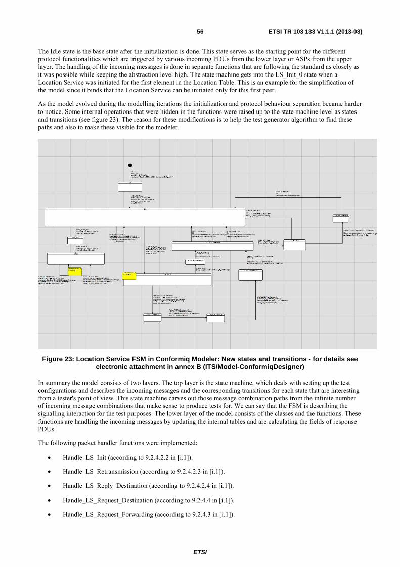
ETSI
ETSI TR 103 133 V1.1.1 (2013-03) 56
The Idle state is the base state after the initialization is done. This state serves as the starting point for the different protocol functionalities which are triggered by various incoming PDUs from the lower layer or ASPs from the upper layer. The handling of the incoming messages is done in separate functions that are following the standard as closely as it was possible while keeping the abstraction level high. The state machine gets into the LS_Init_0 state when a Location Service was initiated for the first element in the Location Table. This is an example for the simplification of the model since it binds that the Location Service can be initiated only for this first peer.
As the model evolved during the modelling iterations the initialization and protocol behaviour separation became harder to notice. Some internal operations that were hidden in the functions were raised up to the state machine level as states and transitions (see figure 23). The reason for these modifications is to help the test generator algorithm to find these paths and also to make these visible for the modeler.
Figure 23: Location Service FSM in Conformiq Modeler: New states and transitions - for details see electronic attachment in annex B (ITS/Model-ConformiqDesigner)
In summary the model consists of two layers. The top layer is the state machine, which deals with setting up the test configurations and describes the incoming messages and the corresponding transitions for each state that are interesting from a tester's point of view. This state machine carves out those message combination paths from the infinite number of incoming message combinations that make sense to produce tests for. We can say that the FSM is describing the signalling interaction for the test purposes. The lower layer of the model consists of the classes and the functions. These functions are handling the incoming messages by updating the internal tables and are calculating the fields of response PDUs.
The following packet handler functions were implemented:
• Handle_LS_Init (according to 9.2.4.2.2 in [i.1]).
• Handle_LS_Retransmission (according to 9.2.4.2.3 in [i.1]).
• Handle_LS_Reply_Destination (according to 9.2.4.2.4 in [i.1]).
• Handle_LS_Request_Destination (according to 9.2.4.4 in [i.1]).
• Handle_LS_Request_Forwarding (according to 9.2.4.3 in [i.1]).

ETSI
ETSI TR 103 133 V1.1.1 (2013-03) 57
• Handle_LS_Reply_Forwarding (according to 9.2.4.3 in [i.1]).
• Handle_Unicast_Destination (according to 9.3.4.4 [i.1]).
In Conformiq Designer™ the user has the option to use requirement traceability links to establish new test goals driven by functional requirements. The requirement links are marked in the model by the "requirement" statement. These marks are used as coverage criteria that can be enabled and disabled independently in the tool's user interface. Every selected requirement becomes a test goal that guides Conformiq Designer™ to look for behaviours that cover the particular requirement. During modelling the following requirements were inserted:
• RQ01 9.2.1.3.1 Initial Address Configuration
• RQ02 9.2.4.2.2 LS_NOT_PENDING
• RQ03 9.2.4.2.2 LS_PENDING
• RQ04 9.2.4.2.3 LS Retransmission
• RQ05 9.2.4.2.3 LS Retransmission Counter
• RQ06 9.2.4.2.4 LS Reply_Neighbor
• RQ07 9.2.4.2.4 LS Reply Not Neighbor
• RQ08 9.2.4.2.4 LS Reply SO LS_Pending:false
• RQ09 9.2.4.2.4 LS Reply SO LS Pending:true
• RQ10 9.2.4.2.4 LS Request Neighbor
• RQ11 9.2.4.3 LS Request Forwarding
• RQ12 9.2.4.3 LS Reply forwarding
• RQ13 9.2.4.4 LS Request Not Neighbor
• RQ14 9.2.4.4 LS Request is the same from another node
Since the Test Purposes were also taken into account during modelling, those parts of the model that clearly belong to a test purpose were also marked with "requirement" statements. The following TP requirements were defined:
• TP01 LS Init
• TP02 No 2nd LS Init
• TP03 Flush LS Buffer after LS Reply
• TP04 LS Buffer FIFO
• TP05 Lifetime Expired
• TP06 LS Request Retransmission
• TP07 LS Retransmission maxRetrans times
• TP08 LS Request Destination
• TP09 LS Request is the same from another node
• TP10 LS Request Forwarding
• TP11 LS Reply Forwarding
• TP12 Unicast Destination
ETSI
ETSI TR 103 133 V1.1.1 (2013-03) 58
6.3.3 Generating test cases with Conformiq Designer™ for case study 2
The goal during the test generation was to produce a test suite that can be compared to the test purposes defined in the Conformance Test Specification. After experimenting with the parameters, we identified two settings that are described in clauses 6.3.3.1 and 6.3.3.2 respectively.
6.3.3.1 Generating test cases for the Test Purposes
We used the first setting set to generate test cases where the goal is to cover all the test purposes with a compact test suite that does not contain too many test cases:
• Project -> Properties -> Conformiq Options:
- Lookahead Depth: Set to the third position
- Only finalized runs: Disabled
- OSI Methodology Support: Enabled
• Coverage Editor:
- Requirements: TPs are Target (12 out of 12: 100 %)
- State Chart (100 %):
� States: Target (13 out of 13: 100 %)
� Transitions: Target (20 out of 20: 100 %)
� 2-Transitions: Don't case
� Implicit Consumption: Don't care
- Conditional Branching: Don't care
- Control Flow (96 %):
� Methods: Target (32 out of 33: 96 %)
The data in parenthesis are showing the percentages of the test goals that are covered by the generated test in that given coverage area.
When the option "Only Finalized Runs" is selected, Conformiq Designer™ generates test cases where the SUT will end in a "clean" state. When this setting is activated, only such test cases are accepted to the generated test suite that would cause all threads in the model to terminate. This setting was disabled and instead 'OSI Methodology Support' was enabled. Selecting this option activates the "OSI Methodology" feature which provides support for generating test suites conforming to the OSI methodology for organizing test cases as laid out in ISO 9646-1 [i.17] standard. All the generated test cases are divided into three sections: Preamble, Body, and Postamble. Every generated test case is automatically named by the name of one of the requirements that is verified in the Body.
Setting the Lookahead Depth to the 3rd position gave 100 % Test Purpose coverage in 12 seconds on an Intel® Core(TM) i5 CPU with 4 cores and 4 GB memory running Windows Vista and produced 18 test cases.
6.3.3.2 Generating test cases for model details
The second setting takes more details of the model into account during test generation. This time not only the Test Purposes were set as goals, but also the requirements that were identified based on the specification. Furthermore, 2-transitions and boundary value analysis was added to the targets of the test generator:
• Project -> Properties -> Conformiq Options:
- Lookahead Depth: Set to the third position
- Only finalized runs: Disabled

ETSI
ETSI TR 103 133 V1.1.1 (2013-03) 59
- OSI Methodology Support: Enabled
• Coverage Editor:
- Requirements: Target (24 out of 26: 92 %)
- State Chart (100 %):
� States: Target (13 out of 13: 100 %)
� Transitions: Target (20 out of 20: 100 %)
� 2-Transitions: (41 out of 41: 100 %)
� Implicit Consumption: Don't care
- Conditional Branching:
� Conditional Branches: Target (32 out of 38: 84 %)
� Boundary Value Analysis: (23 out of 47: 48 %)
- Control Flow (100 %)
� Methods: Target (32 out of 33: 96 %)
The test generator generated 44 test cases still in a reasonable time (1 minute and 8 seconds on an Intel® Core(TM) i5 CPU with 4 cores and 4GB memory running Windows Vista). To find the optimal setting for this parameter one has to experiment with the model and the settings for a while.
6.3.4 Evaluation
In the following, we compare the generated test suites with the test purposes defined in the conformance test specification [i.2]. The test purposes (TP):
• TP/GEONW/PON/LOS/BV/01 Test of first LS invocation for unknown Destination mode
• TP/GEONW/PON/LOS/BV/02 Test of no LS invocation for unknown Destination nodes when LS procedure is already active
• TP/GEONW/PON/LOS/BV/03 Test of packet buffering into LS buffer
• TP/GEONW/PON/LOS/BV/04 Test of LS buffer characteristics: FIFO
• TP/GEONW/PON/LOS/BV/05 Test of LS buffer characteristics: discarding upon LT expiration
• TP/GEONW/PON/LOS/BV/06 Test of LS Request retransmission if no answer is received
• TP/GEONW/PON/LOS/BV/07 Test of LS request retransmission if no answer is received
• TP/GEONW/PON/LOS/BV/08 Test of LS Reply generation by destination node
• TP/GEONW/PON/LOS/BV/09 Test of no LS Reply generation for already answered LS Request packets
• TP/GEONW/PON/LOS/BV/10 Test of LS Request forwarding
• TP/GEONW/PON/LOS/BV/11 Test of LS Reply forwarding
• TP/GEONW/PON/LOS/BV/12 Test flushing of the LS buffer, initiated by the processing of a common header from the target destination
6.3.4.1 Evaluation of the test suite generated to cover the Test Purposes
Using the model described in clause 6.3.2 and setting the parameters of the test generator according to 6.3.3.1 a test suite consisting of 18 test cases is produced by the Conformiq Designer™ tool.

ETSI
ETSI TR 103 133 V1.1.1 (2013-03) 60
The tool generates a Traceability Matrix that makes it possible to check if a Test Purpose is covered by a generated test case as shown in figure 24:
Figure 24: Test Purpose Coverage
All 12 test purposes were covered by the generated test cases. The granularity of the generated test data is at least on the same level as the description in the test purposes. The first three test cases are describing signalling to set up the test configuration.
Further details on the application of Conformiq Designer™ to the ITS location services case study can be found in annex 2.2 of the present document.
6.4 Applying sepp.med MBTsuite to case study 2
6.4.1 Modelling case study 2 with sepp.med MBTsuite
The approach chosen for creating the test model for the ITS case study consists in creating a separate state diagram for each feature of the protocol, based on the system specification and according to its structure. While the state diagram should try to cover all aspects of that feature, interferences with other features should be avoided as much as possible to ensure that the complexity of the model can still be managed with a reasonable amount of efforts. For example in this particular case study targeting the location service functionality of the ITS Geonetworking protocol (see clause 9.2.4 [i.1]), it was chosen to distinguish between source operations (see clause 9.2.4.2 [i.1]), i.e. situations in which the SUT acts as the source for a location service request, and forwarder operations (see clause 9.2.4.3 [i.1]), i.e. situations whereby the SUT is requested to forward incoming requests to their addressed parties and therefore acts as both a sender and a receiver. Therefore two separate state machines were created, with one for source operations and the other one for forwarder operations. Obviously, if for some particular reasons, there is a wish to have a single state machine rather that a set thereof as used here, the individual state machines could then be combined into a single one using branching to distinguish between the different modes.
Given that MBTSuite does not take data structures and architectural structure into account, the only realistic output expected to be generated automatically is a collection of test purposes and the associated procedures for assessing those test purposes.

ETSI
ETSI TR 103 133 V1.1.1 (2013-03) 61
6.4.2 sepp.med MBTsuite model of case study 2
Figure 25 depicts the UML™ state diagram for the ITS GN6 location service functionality in source operation mode.
Figure 25: State diagram for Source Mode of ITS Case Study
6.4.3 Generating test cases with sepp.med MBTsuite for case study 2
The number of test cases generated by MBTSuite seems to depend on two main factors:
• The maximum path length: This appears to be the maximum length which the test generator will explore for a single test case. The default value (50) is perfectly suitable for our model, given that its size is rather small, with the maximum path length being hardly reaching 10 transitions.
• The maximum loop runs: This appears to represent the maximal number of times loops contained in the model will be explored, potentially to reach areas in the model guarded by rules depending on values affected by successive runs. In this particular case study, the maximum loop runs needed to be adapted to the value assigned to the maximal number of LS-Request retransmissions (_ITS_GN_LOCATION_SERVICE_MAX_RETRANS) for full path coverage.

ETSI
ETSI TR 103 133 V1.1.1 (2013-03) 62
A try-and-error approach was followed to find the optimal combination of parameters for the test case generation, i.e. one whereby the maximum coverage could be reached, while generating the lowest possible number of test cases.
Table 12 summarizes the results obtained with various combinations of parameters and shows that while full requirement coverage could already be reached with 31 test cases generated, the optimal test generation is reached by setting the maximal path length parameter to 18 and maximal number of loop runs to 3. This leads to full coverage of all criteria, which should increase confidence in the generated test cases.
Table 12: Parameters and results of the test generation process for the GeoNetworking case study
Parameters Results Max. Path
Length Max. Loop
Runs Number of
Generated Test cases
Edges Coverage (%)
Nodes Coverage (%)
Req. Coverage (%)
10 3 5 62 % 81 % 60 % 15 3 31 87 % 93 % 100 % 16 3 51 91 % 93 % 100 % 17 3 84 91 % 93 % 100 % 18 3 138 100 % 100 % 100 % 20 3 391 100 % 100 % 100 %
6.4.4 Evaluation
The test cases generated with MBTsuite cover all test purposes. A traceability matrix showing the relation between generated test cases and test purposes can be found in clause A.2.3.
6.5 Applying FOKUS MD Tester to case study 2
6.5.1 Modelling case study 2 with FOKUS MD Tester
To model the ITS case study with FOKUS MD Tester, the same approach already applied for the ATM case study was chosen. The biggest challenges in creating the model consisted in finding the right level of abstraction to keep the balance between the complexity of the model and a maximal coverage of the defined test purposes.
6.5.2 FOKUS MD Tester model of case study 2
Just like for the other case studies, the test model for this case study consists of the usual 4 submodels addressing the key aspects of the system. Obviously, the most important diagram of the model is the one for test behaviour, expressed in the form of the test activity diagram displayed in figure 26.

ETSI
ETSI TR 103 133 V1.1.1 (2013-03) 63
Figure 26: Test activity diagram for Source Mode of ITS Case Study

ETSI
ETSI TR 103 133 V1.1.1 (2013-03) 64
6.5.3 Generating test cases with FOKUS MD Tester for case study 2
As described in clause 4.4 the test generation process in MDTester consists of a path exploration of the provided activity diagram, always starting from the initial activity to the final one. The result is a series of activity diagrams, each of which represents a test case.
Figure 27: Sample generated test cases for Source Mode of ITS Case Study

ETSI
ETSI TR 103 133 V1.1.1 (2013-03) 65
Following that approach, a total of 13 test cases were generated using the system's specification as sole input. While, this may appear to be low, compared with the number of test purposes designed manually for this feature (13) a more detailed evaluation of the coverage is required for higher accuracy.
6.5.4 Evaluation
Table 13: Overview of covered TPs for the ITS case study
Test Purpose Covered
TP_GEONW_PON_LOS_BV_01 X
TP_GEONW_PON_LOS_BV_02 X
TP_GEONW_PON_LOS_BV_03 X
TP_GEONW_PON_LOS_BV_04 X
TP_GEONW_PON_LOS_BV_05 X
TP_GEONW_PON_LOS_BV_06 X
TP_GEONW_PON_LOS_BV_07 X
TP_GEONW_PON_LOS_BV_08
TP_GEONW_PON_LOS_BV_09
TP_GEONW_PON_LOS_BV_10
TP_GEONW_PON_LOS_BV_11
TP_GEONW_PON_LOS_BV_12 X
The evaluation of this case study was done, based on the coverage of test purposes defined in the TSS/TP document and used to guide the modelling process (e.g. in selecting which elements of the SUT's behaviour are worth being explicitly modelled and which aspects to ignore). After the test generation process completes, MDTester also generates a traceability matrix summarizing whether the individual test purposes were covered by the generated test cases or not.
Table 13 displays the output for this case study, which indicates that 8 out of 12 test purposes are covered by the model and the generated test cases. This can be explained by the fact that, in the case study, only the behaviour of the SUT in a CF01 configuration was considered, while configurations CF02 and CF03 were left out. Therefore, the behaviour corresponding to TPs associated to CF02 and CF03 were not reflected in the model and logically the generated test cases do not cover them.
Table 14 displays a traceability matrix indicating how each of the individual test cases covers TPs.

ETSI
ETSI TR 103 133 V1.1.1 (2013-03) 66
Table 14: Traceability matrix for ITS Geoloc case study
Test case TP_GEONW_PON_LOS_B
V_01
TP_GEONW_PON_LOS_BV_02
TP_GEONW_PON_LOS
_BV_03
TP_GEONW_PON_LOS
_BV_04
TP_GEONW_PON_LOS_BV_0
5
TP_GEONW_PON_LOS
_BV_06
TP_GEONW_PON_LOS_BV_0
7
TP_GEONW_PON_LOS
_BV_08
TP_GEONW_PON_LOS
_BV_09
TP_GEONW_PON_LOS_B
V_10
TP_GEONW_PON_LOS
_BV_11
TP_GEONW_PON_LOS_B
V_12
ITS_LocService_Test case_1
X X X
ITS_LocService_Test case_2
X X X X
ITS_LocService_Test case_3
X X X X
ITS_LocService_Test case_4
X X X
ITS_LocService_Test case_5
X X X X
ITS_LocService_Test case_6
X X X X X
ITS_LocService_Test case_7
X X X X X
ITS_LocService_Test case_8
X X X X
ITS_LocService_Test case_12
X X X X
ITS_LocService_Test case_13
X X X

ETSI
ETSI TR 103 133 V1.1.1 (2013-03) 67
7 Case study 3: Diameter
7.1 General description of case study 3 The aim of this case study is to apply the selected MBT tools to the Diameter protocol over the Rx interface and evaluate the results.
7.1.1 Overview of case study 3
The Rx reference point is described in TS 129 214 [i.3]. This interface is used to exchange application level session information between the Policy and Charging Rules Function (PCRF) and the Application Function (AF) with the help of the Diameter protocol.
Gy
Subscription Profile
Repository
(SPR)
Rx
Application Function
(AF)
Sp
Gx
Policy and Charging
Enforcement Function
(PCEF)
Policy and Charging Rules
Function
(PCRF)
Gxx
Bearer Binding and Event Reporting Function
(BBERF)
Gateway AN-Gateway
Gz
Offline Charging System
(OFCS)
Online Charging System
(OCS)
Figure 28: Rx reference point at the Policy and Charging Control (PCC) architecture
The Rx reference point is used for example in the IP Multimedia Subsystem (IMS), which is a standardized architecture for telecom operators that want to provide multimedia services. In IMS the Application Function is implemented by the Proxy Call Session Control Function (P-CSCF), which is the first point of contact for an IMS User Equipment (UE). An example scenario for the usage of the Rx interface could be when the UE tries to initiate a new session via the P-CSCF. The session can be initiated with a Session Initiation Protocol (SIP) INVITE message. This message can contain an embedded Session Description Protocol (SDP) payload, which describe the parameters (e.g. codec and other media characteristics) for the requested session. The P-CSCF translates these parameters into DIAMETER and sends it over the Rx interface to the PCRF. The PCRF can decide whether the requested parameters are according to the policies of the operator and therefore it can allow or refuse to setup the session.
TS 129 214 [i.3] defines the Diameter Rx protocol by specifying the Rx reference point and by describing the Rx protocol.
The description of the Rx reference point deals with the reference model and the Policy and Charging Control (PCC) procedures over the Rx reference point. These procedures are the following:

ETSI
ETSI TR 103 133 V1.1.1 (2013-03) 68
• Initial provisioning of session information.
• Modification of session information.
• Gate related procedures.
• AF Session termination.
• Subscription to notification of signalling path status.
• Provisioning of AF signalling flow information.
• Traffic plane events.
The description of the Rx protocol defines the Rx DIAMETER application. The PCRF acts as a Diameter server, in the sense that it is the network element that handles AF session authorization requests for a particular realm. The AF acts as the Diameter client, in the sense that is the network element requesting the authorization of resources for an AF session. Protocol level details such as the Attribute Value Pairs (AVP) used on this interface are also defined here.
7.1.2 Abstract model of case study 3
The external interface of all models are requests/answers defined by the DIAMETER protocol. At least the following data were modelled with all tools:
• DIAMETER request/answer:
- Command code
- AVPs
• AVP:
- Name or code for identification
- Value
The AF role and the PCRF role have different behaviours, therefore they are modelled separately. However they are using the same DIAMETER interface, therefore the data structures can be shared for the two roles. The behaviour model for each role cover at least the core parts of the main procedures described by the standard.
7.1.3 ETSI test cases for case study 3
The TS 101 580-2 [i.4] provides the Test Suite Structure (TSS) and Test Purposes (TP) for the test specifications for the Diameter protocol on the Rx interface as specified in TS 129 214 [i.3].
The test purposes are described in two groups, one for the AF role and the other is for the PCRF role. For each role the TPs are structured according to the procedures. Table 15 gives an overview of the number of defined TPs for each role and for each procedure:
Table 15
AF role PCRF role Initial provisioning of session information 3 3 Modification of session information 3 2 Gate related procedures 1 1 AF session termination 1 2 Subscription to notification of signalling path status 6 5 Traffic plane events 1 1
Each TP is basically a DIAMETER request and answer exchange, where the required starting state of the system is described with the most important AVPs that the messages need to contain. Some of the TPs are building on each other in a sense where a TP can lead the system into a state, which is the required starting state of another TP.

ETSI
ETSI TR 103 133 V1.1.1 (2013-03) 69
The TPs are not covering the DIAMETER base protocol.
7.2 Applying Microsoft® Spec Explorer to case study 3 This clause describes modelling of policy and charging control over Rx protocol [i.3] and further test generation for this functionality with the help of Microsoft® Spec Explorer.
7.2.1 Modelling case study 3 with Spec Explorer
The functionality modelled in this case study is policy and charging control (PCC) over Rx reference point, which is implemented as Diameter-based exchange of messages between Application Function (AF) and Policy Charging and Control Function (PCRF) (see clause 4 [i.3]).
To implement this functionality AF and PCRF establish a session by exchange of Authorization/Authentication Request message, AA-Request, from AF side and Authorization/Authentication Answer message, AA-Answer, from PCRF side, these messages composition is defined in Diameter Network Access Server Application RFC [i.5] and extended with Rx-specific Attribute-Value Pairs, AVPs. Each session has specific properties, concerning what devices and data flows are under control/charging and what related events should be reported to AF. These properties are described in AVPs contained in the initial AA-Request. Several sessions with different settings can be supported simultaneously.
The properties of a session can be modified, with some restrictions, during its lifetime, may be several times. This is performed by exchange of AA-Request from AF side and AA-Answer from PCRF side containing the identifier of existing session.
A session is terminated by request from AF, by exchange of Session Termination Request message, ST-Request, from AF side and Session Termination Answer message, ST-Answer, from PCRF side, also defined in [i.5]. In addition PCRF can ask AF to terminate a session by exchange of Abort Session Request message, AS-Request, from PCRF side and Abort Session Answer message, AS-Answer, from AF side, also defined in [i.5], in result of some events under control.
Notifications on events not requiring session termination, on which AF is subscribed, is performed by exchange of Re-Authorization/Authentication Request message, RA-Request, from PCRF side and Re-Authorization/Authentication Answer message, RA-Answer, from AF side, also defined in [i.5]. Notification data is contained in message AVPs.
NOTE: The standard notes possibility to work outside of a session in (see clause 4.4.1 [i.3]), but formalization of this functionality requires a lot of additional technical details from other standards. For that reason interaction without a session is not modeled and not considered here.
TS 129 214 [i.3] provides a lot of details on session settings and event notification, which cannot be interpreted unambiguously without deep understanding of many related standards and operation of other functional units concerned with policy control and charging. The further exposition is based on some interpretation of the standard [i.3], which may contain some mistakes and definitely does not cover all the mentioned features, only a subset, which can be easily related with externally observable message exchange over Rx interface. The model described below formalizes this partial understanding of the standard [i.3].
The modelling process used is based on the following decisions:
• The single source of information for modelling is the requirements of the PCC over Rx standard [i.3]. Where the text of the standard is unclear, some interpretation is chosen based on the simplicity and consistence with other parts. Incomplete parts are not modelled.
• The functionality of PCC is modelled on an abstract level, without taking into account other events and data then the ones directly related with message exchange over Rx interface. The events initiating such message exchange (occurring in other parts of a system) are modelled without any details and data, just as abstract events of several types. The data of Diameter messages used in exchange over Rx interface is modelled based on the main distinctions between messages concerning events of different types.
• The model developed consists of two executable models of AF and PCRF functional units. These models describe only a part of behaviour of such units, even the behaviour related with message exchange over Rx interface is specified only partially. Other functionality and data are not specified at all.

ETSI
ETSI TR 103 133 V1.1.1 (2013-03) 70
• The data structures of messages used was modelled only partially. Each message is modelled as having the session identifier and (maybe) several additional AVPs sufficient to distinguish it from messages related with other event types. Only AVPs mentioned in the description of the corresponding distinguishing procedure are modelled, all other AVPs, both optional and mandatory, but not mentioned in distinguishing algorithm or not playing a decisive role in it, are skipped.
• Two techniques are used to detect the errors in the model: model reviews and model simulation on a set of simple scenarios. Both approaches help to find some errors.
The following decisions are made concerning the general structure of the model:
• The model is synchronous, that is it operates by processing external events and providing outputs on them without parallel processing of several events. Synchronous modelling is possible due to the structure of Rx protocol itself — its operation can be represented in synchronous way, although implementations can work asynchronously.
• The model consists of two parts: model of AF unit and model of PCRF unit.
• AF unit model interface includes the following events:
- Events causing message sending through Rx interface:
� session initiation (see clause 4.4.1 [i.3]);
� session modification (see clause 4.4.2 [i.3]);
� session termination (see clause 4.4.4 [i.3]).
- Income of a message from PCRF unit:
Introduction of special events causing message sending slightly increase the complexity of adaptation of tests created on the base of the model.
• PCRF model interface includes the following events:
- Events causing message sending through Rx interface:
� Resource allocation failure (see clause 4.4.3 [i.3]);
� IP-CAN session termination (see clause 4.4.6.1 [i.3]);
� Service data flow deactivation (see clause 4.4.6.2 [i.3]); such event type is modelled only partially – the situation when it concerns all flows related with a session is not modelled, mostly because it leads to more effort in test adaptation;
� Signalling path status notification (see clause 4.4.6.3 [i.3]);
� IP-CAN type change (see clause 4.4.6.4 [i.3]);
� Usage reporting (see clause 4.4.6.6 [i.3]).
Access network charging information notification (see clause 4.4.6.5 [i.3]) is not modelled, because the conditions, under which subscritption on such notification is given, are not clearly specified in the standard text.
- Income of a message from AF unit.
• The following decisions concerning session settings, possibility of their modification, and subscription on different events are made:
- Only the following types of sessions are modelled:
� Default (see clause 4.4.1 [i.3]);
� Using sponsored connections (see clause 4.4.1, paragraph 10 [i.3]);
� Subscribed to usage reporting (see clause 4.4.1, paragraph 12 [i.3]);

ETSI
ETSI TR 103 133 V1.1.1 (2013-03) 71
� Subscribed to IP-CAN type change notifications (see clause 4.4.1, paragraph 26 [i.3]);
� Enabling/disabling specific IP flows (see clause 4.4.3 [i.3]);
� Subscribed to notifications of signaling path status (see clause 4.4.5 [i.3]);
� Providing AF signaling flow data (see clause 4.4.5a [i.3]).
- The following modifications of session settings are allowed in the model:
� Sessions of the first three types listed above can be modified into each other;
� Session subscribed to notifications of signaling path status can be modified into the one providing AF signaling flow data.
- An event can occur for a session only if such type of events is allowed for sessions of the corresponding type:
� Resource allocation failure is allowed only for sessions enabling/disabling specific IP flows;
� IP-CAN session termination and service data flow deactivation allowed for all sessions;
� Signalling path status notification is allowed for sessions subscribed to notifications of signaling path status or providing AF signaling flow data;
� IP-CAN type change is allowed only for sessions subscribed to IP-CAN type change notifications;
� Usage reporting is allowed only for sessions subscribed to usage reporting.
• The modular structure of the model is unrelated with the structure of the standard requirements — because the model is abstracted from most details, often its one part corresponds to several different places in the standard text. For example, session initiation and termination is processes in same units, in spite of the session settings.
• For both functional units their behaviour is modelled in the corresponding model unit and their communication is modelled as external events, so that they can be considered as separate and independent models of AF and PCRF, without any constraints on their possible communication (it made possible, but not obligatory for test generation purposes).
7.2.2 Spec Explorer model of case study 3
The Spec Explorer model of policy and charging control over Rx interface consists from the following parts, all written in C#.
• Common types module (the file RxTypes.cs forming a separate project in the Visual Studio® solution), containing definition of all the data types used in external events. These definitions are made separate because they are used both in the model and in the abstract description of implementation interface needed for test generation. In addition this module contains test data pools for data used in tests — AF- and PCRF-related events, command messages. The complete list of data types defined in this module is the following:
- Enumerations:
� AFEventKind enumeration representing possible types of AF-related events (session initiation, modification, or termination);
� PCRFEventKind enumeration representing possible types of PCRF-related events (causing notification of AF through Rx interface);
� SessionKind enumeration representing possible types of sessions (see above);
� SpecActionKinds class providing named constants for Specific-Action AVP contents (see clause 5.3.13 [i.3]);
� CommandKind enumeration representing possible types of commands used in Rx protocol (see clause 5.6 [i.3]).

ETSI
ETSI TR 103 133 V1.1.1 (2013-03) 72
- Event-related and protocol packet data structures:
� AFEvent representing data structure of AF-related events;
� PCRFEvent representing data structure of PCRF-related events;
� AVP representing common data structure of AVPs used in messages exchanged through Rx interface. Also contains auxiliary methods for construction of AVP objects of different kinds, these methods are used both in AF model and in test data preparation for PCRF model;
� Command representing common data structure of Rx protocol commands (see clause 5.6 [i.3]). Also contains auxiliary methods processing AA-Request command and determining the type of session it describes.
- Test data pools:
� SessionIdPool contains named constants for several session identifiers;
� AFEventPool contains definition and initialization of several AF-related events;
� PCRFEventPool contains definition and initialization of several PCRF-related events;
� CommandPool contains definition and initialization of several command instances, part of them is used for testing AF unit and part – for testing PCRF unit.
• The main model module (the file RxModelProgram.cs) containing the following items:
- Enumerations:
� AFSessionStatus representing internal status of a session from AF viewpoint;
� PCRFSessionStatus representing internal status of a session from PCRF viewpoint.
- Data structure types for internal data:
� AFSessionData representing status and type of a session supported by AF unit;
� PCRFSessionData representing status and type of a session supported by PCRF unit.
- AF unit behaviour model — AFModelProgram class — modelling single AF unit (so all its data fields and methods are static) and having the following elements:
� Data fields:
� sessions representing maintained session data. Implemented as a map of session identifiers to session status and type.
� Model operations corresponding to operations of the interface under test:
� Command GetRxMessageRule(Command c) models processing an Rx message from PCRF unit;
� Command ReactOnEventRule(string sid, AFEvent e) models processing of an event related with a session having sid identifier.
- PCRF unit behaviour model — PCRFModelProgram class — modelling single PCRF unit (so all its data fields and methods are static) and having the following elements:
� Data fields:
� sessions representing maintained session data. Implemented as a map of session identifiers to session status and type.

ETSI
ETSI TR 103 133 V1.1.1 (2013-03) 73
� Model operations corresponding to operations of the interface under test:
� Command GetRxMessageRule(Command c) models processing an Rx message from AF unit;
� Command ReactOnEventRule(string sid, PCRFEvent e) models processing of an event related with a session having sid identifier.
- Runner auxiliary class implementing several operation scenarios for model simulation and testing.
7.2.3 Generating test cases with Spec Explorer for case study 8
Due to the complexity of the developed model a straightforward test generation is problematic. To select a relevant set of scenarios for test generation a target test coverage criterion has to be determined.
The coverage of specific statements of standard requirements is taken as a target test coverage criterion in this case study. To select the relevant set of requirements the standard text [i.3] related with processing of the chosen interface events (see clause 7.2.1) is analysed and the statements presented in table 16 are selected — only the requirements presented below in table 16 are modelled. Both the paragraphs from [i.3] cited and other parts of the standard text [i.3] may also contain requirements, which are not modelled in this case study (if some text is skipped from the presented clause, it is marked with […]).

ETSI
ETSI TR 103 133 V1.1.1 (2013-03) 74
Table 16
N Position in the standard text
[i.3]
Requirement statement Target module of the
requirement 1 [i.3] 4.4.1,
paragraph 1 When a new AF session is being established and media information for this AF session is available at the AF and the related media require PCC supervision, the AF shall open an Rx Diameter session with the PCRF for the AF session using an AA-Request command. […].
AF, PCRF
2 [i.3] 4.4.1, paragraph 10
For sponsored data connectivity, the AF shall provide the application service provider identity and the sponsor identity to the PCRF by including the Application-Service-Provider-Identity AVP and the Sponsor-Identity AVP in the Sponsored-Connectivity-Data AVP in the AA-Request.
AF, PCRF
3 4.4.1, paragraph 12
To support the usage monitoring of sponsored data connectivity, the AF may also include the Granted-Service-Unit AVP in the Sponsored-Connectivity-Data AVP and the Specific-Action AVP set to the value USAGE_REPORT in the AA-Request to request notification when the usage threshold has been reached.
AF, PCRF
4 4.4.1, paragraph 20
When the PCRF receives an initial AA-Request from the AF, the PCRF shall perform session binding as described in TS 129.213 [i.15].
PCRF (see 1)
5 4.4.1, paragraph 26
The AF may request notifications of specific IP-CAN session events through the usage of the Specific-Action AVP in the AA-Request command. The PCRF shall make sure to inform the AF of the requested notifications in the event that they take place.
AF, PCRF
6 4.4.1, paragraph 28
The PCRF shall reply with an AA-Answer to the AF. […]. PCRF, AF
7 4.4.2, paragraph 1
The AF may modify the session information at any time (e.g. due to an AF session modification or internal AF trigger) by sending an AA-Request command to the PCRF containing the Media-Component-Description AVP(s) with the updated Service Information. The AF shall send an AA-Request command to the PCRF, only after the previous AARequest has been acknowledged.
AF, PCRF
8 4.4.2, paragraph 5
For sponsored data connectivity, the AF shall provide the application service provider identity and the sponsor identity to the PCRF by including Application-Service-Provider-Identity AVP and the Sponsor-Identity AVP in the Sponsored-Connectivity-Data AVP in the AA-Request.
AF, PCRF
9 4.4.2, paragraph 6
To support the usage monitoring of sponsored data connectivity, the AF may also include the Granted-Service-Unit AVP in the Sponsored-Connectivity-Data AVP in the AA-Request.
AF, PCRF
10 4.4.2, paragraph 10
The PCRF shall reply with an AA-Answer to the AF. […]. PCRF, AF
11 4.4.3, paragraph 1
Depending on the application, in the Service Information provision, the AF may instruct the PCRF when the IP flow(s) are to be enabled or disabled to pass through the IP-CAN. The AF does this by sending the AA-Request message containing the Media-Component- Description AVP(s) that contains the flow status information (in the Flow-Status AVP) for the flows to be enabled or disabled.
AF, PCRF
12 4.4.3, paragraph 3
If a Media-Sub-Component AVP under a Media-Component-Description AVP contains a Flow-Usage AVP with the value RTCP, then the corresponding RTCP IP Flows in both directions shall be enabled even if the Flow-Status AVP under the Media-Sub-Component AVP is set to ENABLED-UPLINK, ENABLED-DOWNLINK, ENABLED, or DISABLED.
AF, PCRF
13 4.4.3, paragraph 4
The PCRF shall reply with an AA-Answer and shall include the Access-Network-Charging-Identifier(s) available at this moment. […].
PCRF, AF
14 4.4.3, paragraph 6
If the PCRF modifies existing PCC/QoS rules based on the updated service information and the modification fails due to resource allocation failure as specified in 3GPP TS29.212 and if requested by the AF, the PCRF shall send an RAR command to the AF with the Specific-Action AVP set to the value INDICATION_OF_FAILED_RESOURCES_ALLOCATION to report the modification failure. The AF shall send an RAA command to acknowledge the RAR command.
PCRF, AF
15 4.4.4, paragraph 1
When an AF session is terminated, if the AF had received a successful AA-Answer for the initial AA-Request, the AF shall send a Session-Termination-Request command to the PCRF. Otherwise, the AF shall wait for the initial AAAnswer to be received prior to sending the Session-Termination-Request command to the PCRF.
AF, PCRF
16 4.4.4, paragraph 2
When the PCRF receives a ST-Request from the AF, indicating an AF session termination, it shall acknowledge that request by sending a ST-Answer to the
PCRF, AF

ETSI
ETSI TR 103 133 V1.1.1 (2013-03) 75
N Position in the standard text
[i.3]
Requirement statement Target module of the
requirement AF. […]
17 4.4.4, paragraph 5
[…] The PCRF shall send then the ST-Answer to the AF […] PCRF, AF
18 4.4.5, paragraph 1
An AF may subscribe to notifications of the status of the AF Signalling transmission path. To do so, the AF shall open an Rx Diameter session with the PCRF for the AF signalling using an AA-Request command. The AF shall provide […] the Specific-Action AVP requesting the subscription to "INDICATION_OF_LOSS_OF BEARER" and/or 'INDICATION_OF_RELEASE_OF_BEARER'. The AF shall additionally provide a Media-Component-Description AVP including a single Media-Sub-Component AVP with the Flow-Usage AVP set to the value "AF_SIGNALLING". The Media-Component-Description AVP shall contain the Media-Component-Number AVP set to '0'.
AF, PCRF
19 4.4.5, paragraph 2
If the procedures in clause 4.4.5a are not applied, the Media-Sub-Component AVP shall contain the Flow-Number AVP set to '0', and the rest of AVPs within the Media-Component-Description and Media-Sub-Component AVPs shall not be used in this case.
AF, PCRF
20 4.4.5, paragraph 3
When the PCRF receives an AA-Request as described in the preceding paragraph from the AF, the PCRF shall perform session binding as described in TS 129.213 [i.15] and acknowledges the AAR command by sending an AA-Answer command to the AF.
PCRF, AF (see 1,4,6,22)
21 4.4.5, paragraph 5
The AF may cancel the subscription to notifications of the status of the AF Signalling transmission path at any time. In that case, the AF shall use a Session-Termination-Request (STR) command to the PCRF, which shall be acknowledged with a Session-Termination-Answer (STA) command.
AF, PCRF (see 14)
22 4.4.5a, paragraph 1
An AF may provision information about the AF signalling IP flows between the UE and the AF. To do so, the AF shall make use of an Rx Diameter session already opened with the PCRF if an Rx Diameter session related to the AF signalling is already established. The AF may modify an already open Rx Diameter session related to the AF signalling (e.g. an Rx Diameter session established for the purpose of subscription to notification of signalling path status as described in clause 4.4.5) or it may open a new Rx Diameter session related to the AF signalling if none exists.
AF, PCRF
23 4.4.5a, paragraph 2
[…]. The AF shall additionally provide a Media-Component-Description AVP including one or more Media-Sub-Component AVP(s) representing the AF signalling IP flows. The Media-Component-Description AVP shall contain the Media-Component-Number AVP set to "0". Each Media-Sub-Component AVP representing an AF signalling IP flow shall contain the Flow-Number AVP set according to the rules described in annex B and one or two Flow-Description AVP(s) set to the IP flows of the AF signalling. Additionally, the Media-Sub-Component AVP shall include the Flow-Usage AVP set to the value "AF_SIGNALLING", the Flow-Status AVP set to "ENABLED" and the AF-Signalling-Protocol AVP set to the value corresponding to the signalling protocol used between the UE and the AF.
AF, PCRF
24 4.4.5a, paragraph 3
When the PCRF receives from the AF an AA-Request as described in the preceding paragraph, the PCRF shall perform session binding as described in TS 129.213 [i.15] and shall acknowledge the AAR command by sending an AA-Answer command to the AF.
PCRF, AF (see 1,4,6,18)
25 4.4.5a, paragraph 5
The AF may de-provision the information about the AF signaling IP flows at any time. To do that the AF shall close the Rx Diameter session by sending a Session-Termination-Request (STR) command to the PCRF, which shall be acknowledged with a Session-Termination-Answer (STA) command.
AF, PCRF (see 14,19)
26 4.4.6.1, paragraph 1
When an IP-CAN session is terminated, the PCRF shall inform the AF about the IP-CAN session termination by sending an ASR (abort session request) command to the AF on each active Rx Diameter session.
PCRF, AF
27 4.4.6.1, paragraph 2
When the AF receives the ASR command, it shall acknowledge the command by sending an ASA (abort session answer) command to the PCRF and indicate the termination of the session by sending an STR (session termination request) command to the PCRF. The PCRF shall acknowledge the termination of the session by sending an STA (session termination answer) command to the AF.
AF, PCRF
28 4.4.6.2, paragraph 1
[…]When the PCRF gets the knowledge that one or more SDFs have been deactivated, (e.g. due to a bearer release or loss of bearer or out of credit condition), the PCRF shall inform the AF accordingly if the AF has previously subscribed using the Specific-Action AVP in the AAR command.
PCRF, AF

ETSI
ETSI TR 103 133 V1.1.1 (2013-03) 76
N Position in the standard text
[i.3]
Requirement statement Target module of the
requirement 29 4.4.6.2,
paragraph 2 When not all the service data flows within the AF session are affected, the PCRF shall inform the AF by sending an RAR (re-authorization request) command. The RAR command shall include the deactivated IP Flows encoded in the Flows AVP and the cause encoded in the Specific-Action AVP.
PCRF, AF
30 4.4.6.2, paragraph 3
When the AF receives the RAR command, it shall acknowledge the command by sending an RAA (re-authorization answer) command to the PCRF. The AF may also update the session information by sending an AAR (AA-request) command to the PCRF.
AF, PCRF
31 4.4.6.3, paragraph 1
In the event that the PCRF is notified of the loss or release of resources associated to the PCC/QoS Rules corresponding with AF Signalling IP Flows, the PCRF shall inform the AF about the Loss of the Signalling Transmission path by sending a Re-Authorization Request (RAR) command to the AF. The RAR shall include the Specific-Action AVP set to the value "INDICATION_OF_LOSS_OF_BEARER" or 'INDICATION_OF_RELEASE_OF_BEARER' and the deactivated IP Flow encoded in the Flows AVP.
PCRF, AF
32 4.4.6.3, paragraph 3
When the AF receives the RAR command, it shall acknowledge the command by sending an RAA command to the PCRF.
AF, PCRF
33 4.4.6.4 If the AF has successfully subscribed to change notifications in UE's IP-CAN type and RAT type, the PCRF shall send an RAR command when a corresponding event occurs, i.e. when the UE's IP-CAN type or RAT type (if the IP-CAN type is GPRS), changes. In this case the RAR from the PCRF shall include the Specific-Action AVP for the subscribed event and include the IP-CAN-Type AVP and RAT-Type AVP (if the IP-CAN type is GPRS) for the UE's new IPCAN/RAT. […].
PCRF, AF
34 4.4.6.6, paragraph 1,2
When the AF session is associated with a sponsor and the AF provided usage monitoring thresholds for such sponsor to the PCRF when the Rx Diameter session was established or modified, the PCRF shall report accumulated usage to the AF, when - the PCRF detects that the usage threshold provided by the AF has been reached. […].
PCRF, AF
35 4.4.6.6, paragraph 5
When the PCRF detects that the usage threshold has been reached, the PCRF shall report the accumulated usage as provided by the PCEF to the AF in a RA-Request (RAR) command with the Specific-Action AVP set to the value USAGE_REPORT. […]
PCRF, AF
36 4.4.6.6, paragraph 6
The accumulated usage shall be reported in the Used-Service-Unit AVP within the Sponsored-Connectivity-Data AVP.
PCRF, AF
37 4.4.6.6, paragraph 7
If the AF receives a RAR command indicating the usage threshold is reached, the AF may terminate the AF session or provide a new usage threshold in the Granted-Service-Unit AVP within the Sponsored-Connectivity-Data AVP to the PCRF in the AAR command. Alternatively, the AF may allow the session to continue without providing new usage threshold in the AAR command.
AF, PCRF
Only a few of the requirements statements presented in table 17 are essential for a coverage measuring. The items presented in the table 17 were chosen as branching marks in terms of standard requirements. They are also partitioned into requirements to AF and PCRF modules.

ETSI
ETSI TR 103 133 V1.1.1 (2013-03) 77
Table 17
ID Module Row(s) in table 16
Position(s) in the standard text [i.3]
Notes
R01 AF 6, 10 4.4.1/28, 4.4.2/10 Processing of AA-Answer R02 AF 14, 30, 32, 37 4.4.3/6, 4.4.6.2/3,
4.4.6.3/3, 4.4.6.6/7 Processing of RA-Request
R03 AF 27 4.4.6.1/2 Processing of AS-Request R04 AF 17, 21, 25 4.4.4/5, 4.4.5/5,
4.4.5a/5 Processing of ST-Answer
R05 AF 1 4.4.1/1 Creation of a default session R06 AF 2 4.4.1/10 Creation of a session with sponsored connection R07 AF 3 4.4.1/12 Creation of a session subscribed to usage reporting R08 AF 18, 19 4.4.5/1-2 Creation of a session subscribed to notifications of signaling
path status R09 AF 23 4.4.5a/2 Creation of a session providing AF signaling flow data R10 AF 7 4.4.2/1 Modification of a session to default one R11 AF 8 4.4.2/5 Modification of a session to a one with sponsored connection R12 AF 9 4.4.2/6 Modification of a session to a one subscribed to usage
reporting R13 AF 22, 23 4.4.5a/1-2 Modification of a session to a one providing AF signaling flow
data R14 AF 15 4.4.4/1 Session termination R15 PCRF 7 4.4.2/1 Processing modification request of a session to default one R16 PCRF 8 4.4.2/5 Processing modification request of a session to a one with
sponsored connection R17 PCRF 9 4.4.2/6 Processing modification request of a session to a one
subscribed to usage reporting R18 PCRF 22, 23 4.4.5a/1-2 Processing modification request of a session to a one
providing AF signaling flow data R19 PCRF 15 4.4.4/1 Processing of ST-Request R20 PCRF 35, 36 4.4.6.6/5-6 Adding usage reporting to ST-Answer R21 PCRF 27 4.4.6.1/2 Processing of AS-Answer R22 PCRF 14, 30, 32, 37 4.4.3/6, 4.4.6.2/3,
4.4.6.3/3, 4.4.6.6/7 Processing of RA-Answer
R23 PCRF 1 4.4.1/1 Processing creation request of a default session R24 PCRF 5 4.4.1/26 Processing creation request of a session subscribed to IP-
CAN type change notifications R25 PCRF 11, 12, 13 4.4.3/1-3 Processing creation request of a session enabling/disabling
specific IP flows R26 PCRF 2 4.4.1/10 Processing creation request of a session with sponsored
connection R27 PCRF 3 4.4.1/12 Processing creation request of a session subscribed to usage
reporting R28 PCRF 18, 19 4.4.5/1-2 Processing creation request of a session subscribed to
notifications of signaling path status R29 PCRF 23 4.4.5a/2 Processing creation request of a session providing AF
signaling flow data R30 PCRF 14 4.4.3/6 Notification on failed resource allocation R31 PCRF 26 4.4.6.1/1 Notification on IP-CAN session termination R32 PCRF 28, 29 4.4.6.2/1-2 Notification on service data flow deactivation R33 PCRF 31 4.4.6.3/1 Notification on signalling path status R34 PCRF 33 4.4.6.4 Notification on IP-CAN type change R35 PCRF 34, 35, 36 4.4.6.6/1,5-6 Usage reporting
The target coverage criterion chosen for test selection is coverage of all requirements presented in table 17.
The Spec Explorer model code is marked with requirement capture statements, corresponding to the selected requirements. Such a statement is written in a code block corresponding to the specified requirement. These marks can be made visible on the state-transition graphs of model exploration generated by the tool, and so the tool indirectly helps to design a set of scenarios covering all the coverage goals chosen.

ETSI
ETSI TR 103 133 V1.1.1 (2013-03) 78
The main prerequisite for creating a covering set of scenarios is a need for the corresponding set of test data. In this case study according to the decisions made before modelling — that single AF and PCRF units are modelled and all their communications are presented as various incoming packets and events, initiating specific actions, — one needs to prepare sets of packets and events sufficient to reach all the coverage goals selected. This needs rather trivial (in this case study) analysis of reachability of the coverage goals. To reach them all it is sufficient to use command message of all different types (also related with different types of sessions) and events of all different types.
The development of the set of scenarios is partitioned into several parts:
• Scenarios for testing AF unit:
- The first scenario covers creation, modification, permissible events processing, and termination for default session, session with sponsored connection, and session subscribed on usage reporting.
- The second scenario covers creation, modification, permissible events processing and termination for session subscribed to notifications of signaling path status and session providing AF signaling flow data.
- The third scenario covers creation, event processing, and termination for two different sessions to check possibility of a unit to identify correctly events related with different sessions.
• Scenarios for testing PCRF unit:
- The first scenario covers creation, modification, non-specific events processing, and termination for default session, session with sponsored connection, and session subscribed on usage reporting.
- The second one covers creation a default session, modification it into a session subscribed on usage reporting, processing usage reporting, and termination.
- The third one covers creation, specific events processing, and termination for session subscribed on IP-CAN type change notifications.
- The fourth one covers creation, specific events processing, and termination for session enabling/disabling specific IP flows.
- The fifth scenario covers creation, modification, specific events processing, and termination for session subscribed to notifications of signaling path status and session providing AF signaling flow data.
- The last, sixth scenario covers creation and termination for two different sessions to check possibility of a unit to identify correctly events related with different sessions.
Spec Explorer generates 35 tests for AF unit, and 54 tests for PCRF unit using the presented slices. Total number of the tests generated is 89.
7.2.4 Evaluation
Two criteria are used to evaluate the test suite generated: coverage of requirement statements (essential for branches of events processing, see table 17) and coverage of the test purposes for Rx protocol, presented in [i.4].

ETSI
ETSI TR 103 133 V1.1.1 (2013-03) 79
Table 18 presents test purposes from [i.4].
Table 18
ID TP Id used in [i.4] Test sequence Description TP01 TP_AF_IPS_01 AF sends AA-Request. Test of (default) session initiation. TP02 TP_AF_IPS_02 After sending AA-Request AF accepts
AA-Answer. Test of AA-Answer processing during session establishment.
TP03 TP_AF_IPS_03 AF sends AA-Request containing Sponsored-Connectivity-Data AVP.
Test of initiation a session with sponsored connection.
TP04 TP_AF_MSI_01 After session is established AF sends AA-Request.
Test of (default) session modification.
TP05 TP_AF_MSI_02 After session is established and AF sent AA-Request, AF accepts AA-Answer.
Test of AA-Answer processing during session modification.
TP06 TP_AF_MSI_03 After session is established AF sends AA-Request containing Sponsored-Connectivity-Data AVP.
Test of session modification into a session with sponsore connection.
TP07 TP_AF_GRP_01 After session is established AF receives RA-Request with notification on failed resources allocation and sends RA-Answer.
Test of processing of notification on failed resources allocation.
TP08 TP_AF_ST_01 After session is established AF sends ST-Request.
Test of (default) session termination.
TP09 TP_AF_SN_01 AF sends AA-Request for subscription on notification of signalling path status.
Test of initiation a session with subscription on notification of signalling path status.
TP10 TP_AF_SN_02 AF sends AA-Request for subscription on notification of signalling path status without provisioning of AF signalling flow information.
Test of initiation a session with subscription on notification of signalling path status without provisioning of AF signalling flow information.
TP11 TP_AF_SN_03 After session with subscription on notification of signalling path status is established AF sends ST-Request.
Test of termination of a session with subscription on notification of signalling path status.
TP12 TP_AF_SN_04 After session with subscription on notification of signalling path status and without provisioning of AF signalling flow information is established AF sends ST-Request.
Test of termination of a session with subscription on notification of signalling path status and without provisioning of AF signalling flow information.
TP13 TP_AF_SN_05 AF sends AA-Request for session with provisioning of AF signalling flow information.
Test of initiation a session with provisioning of AF signalling flow information.
TP14 TP_AF_SN_06 After session with provisioning of AF signalling flow information is established AF sends ST-Request.
Test of termination of a session with provisioning of AF signalling flow information.
TP15 TP_AF_TPE_01 After session is established AF receives AS-Request, after which it sends AS-Answer and ST-Request.
Test of session termination after receiving AS-Request.
TP16 TP_PCRF_IPS_01 PCRF receives AA-Request and sends AA-Answer in response.
Test of (default) session initiation of PCRF unit.
TP17 TP_PCRF_IPS_02 PCRF receives AA-Request with subscription on usage reporting and sends AA-Answer.
Test of initiation of a session subscribed on usage reporting.
TP18 TP_PCRF_IPS_03 PCRF receives AA-Request with sponsored connection data and sends AA-Answer.
Test of initiation of a session with sponsored connection.
TP19 TP_PCRF_MSI_01 After session is established PCRF receives AA-Request and sends AA-Answer.
Test of (default) session modification.
TP20 TP_PCRF_MSI_02 After session is established PCRF receives AA-Request with sponsored connection data and sends AA-Answer.
Test of a session modification into a session with sponsored connection.
TP21 TP_PCRF_GRP_01 After session is established PCRF sends RA-Request to notify on failed resource allocation.
Test of generation of notification on failed resources allocation.
TP22 TP_PCRF_ST_01 After session is established PCRF receives ST-Request and sends ST-Answer.
Test of termination of a default session.
TP23 TP_PCRF_ST_02 After session with sponsored connection data is established PCRF receives ST-Request and sends ST-Answer
Test of termination of a session with sponsored connection data.
TP24 TP_PCRF_SN_01 PCRF receives AA-Request with subscription on notification on signaling path status and sends AA-Answer.
Test of initiation of a session with subscription on notification on signaling path status.

ETSI
ETSI TR 103 133 V1.1.1 (2013-03) 80
ID TP Id used in [i.4] Test sequence Description TP25 TP_PCRF_SN_02 PCRF receives AA-Request subscribing to
notifications of the status of the AF without the provision of AF signaling flow information and sends AA-Answe.
Test of initiation of a session with subscription on notification on signaling path status without the provision of AF signaling flow information.
TP26 TP_PCRF_SN_03 After session subscribed to notifications of the status of the AF without the provision of AF signaling flow information is established PCRF receives ST-Request and sends ST-Answer.
Test of termination of a session without the provision of AF signaling flow information.
TP27 TP_PCRF_SN_04 PCRF receives AA-Request with subscription on notification on signaling path status with the provision of AF signaling flow information and sends AA-Answer.
Test of initiation of a session with subsciprtion on notification on signaling path status with the provision of AF signaling flow information.
TP28 TP_PCRF_SN_05 After session subscribed to notifications of the status of the AF with the provision of AF signaling flow information is established PCRF receives ST-Request and sends ST-Answer.
Test of termination of a session with the provision of AF signaling flow information.
TP29 TP_PCRF_TPE_01 After session is established PCRF sends AS-Request to notify on IP-CAN session termination.
Test of notification of IP-CAN session termination.
TP30 TP_PCRF_TPE_02 After session is established and PCRF sent AS-Request to notify on IP-CAN session termination it receives AS-Answer and ST-Request and sends ST-Answer.
Test of session termination after notification on IP-CAN session termination.
TP01-TP15 in the table 18 concern AF unit behaviour, TP16-TP30 concern PCRF unit behaviour.
Table 19 demonstrates coverage of the presented test purposes for AF unit by the test generated. The sign 'X' means that the test purpose is covered with very similar sequence of actions, the sign 'V' means that the test purpose is covered with another action sequence (the test suite contains a sequence of actions checking the same properties).
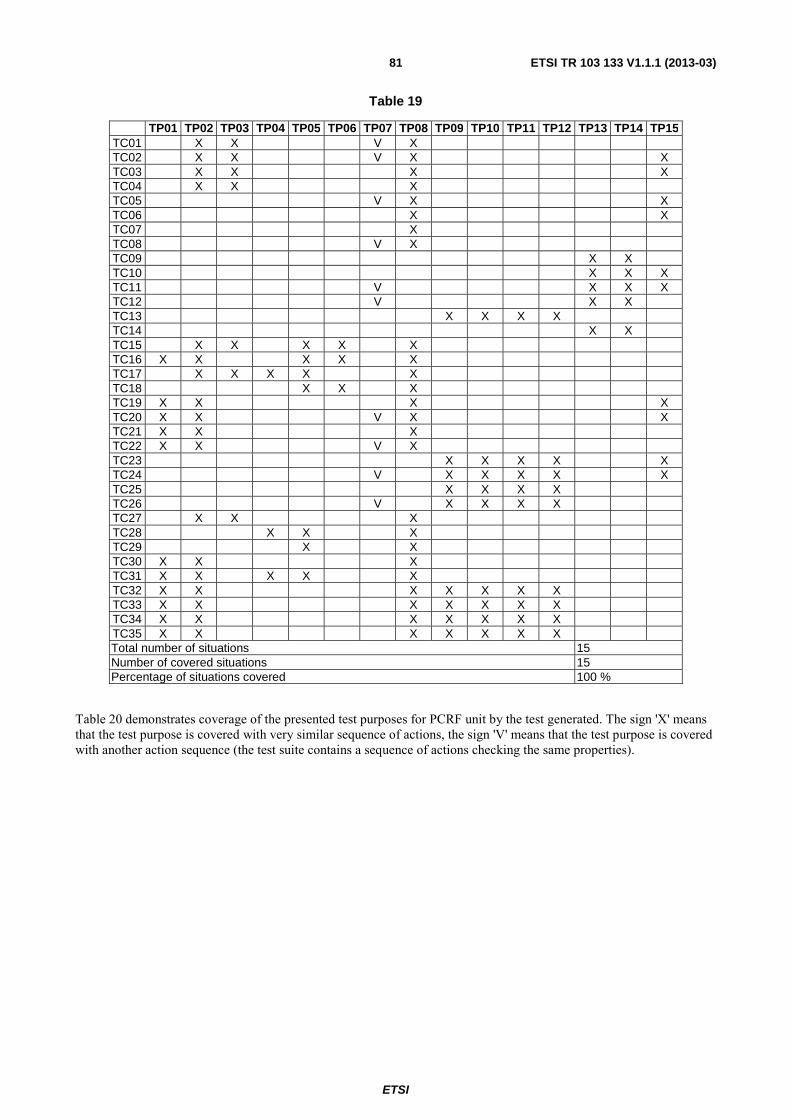
ETSI
ETSI TR 103 133 V1.1.1 (2013-03) 81
Table 19
TP01 TP02 TP03 TP04 TP05 TP06 TP07 TP08 TP09 TP10 TP11 TP12 TP13 TP14 TP15 TC01 X X V X TC02 X X V X X TC03 X X X X TC04 X X X TC05 V X X TC06 X X TC07 X TC08 V X TC09 X X TC10 X X X TC11 V X X X TC12 V X X TC13 X X X X TC14 X X TC15 X X X X X TC16 X X X X X TC17 X X X X X TC18 X X X TC19 X X X X TC20 X X V X X TC21 X X X TC22 X X V X TC23 X X X X X TC24 V X X X X X TC25 X X X X TC26 V X X X X TC27 X X X TC28 X X X TC29 X X TC30 X X X TC31 X X X X X TC32 X X X X X X X TC33 X X X X X X X TC34 X X X X X X X TC35 X X X X X X X Total number of situations 15 Number of covered situations 15 Percentage of situations covered 100 %
Table 20 demonstrates coverage of the presented test purposes for PCRF unit by the test generated. The sign 'X' means that the test purpose is covered with very similar sequence of actions, the sign 'V' means that the test purpose is covered with another action sequence (the test suite contains a sequence of actions checking the same properties).

ETSI
ETSI TR 103 133 V1.1.1 (2013-03) 82
Table 20
TP16 TP17 TP18 TP19 TP20 TP21 TP22 TP23 TP24 TP25 TP26 TP27 TP28 TP29 TP30 TC01 V X TC02 X X TC03 X X X TC04 X X X TC05 X X X TC06 X X X TC07 X X X TC08 X X X TC09 X X X TC10 X X X TC11 X X X TC12 X X X TC13 X X X TC14 X X TC15 X X X TC16 X X TC17 V X X X TC18 X X X TC19 X V X X TC20 X X X TC21 X V X X TC22 X V X X TC23 X V X X TC24 X X V X X TC25 X V X X TC26 X X X TC27 X V TC28 X X X X TC29 V V TC30 X X X TC31 X V TC32 X X TC33 X X TC34 X X X TC35 X X X TC36 X X TC37 X X X TC38 X X X TC39 X X X TC40 X V V TC41 X X TC42 X X X X TC43 X X X X TC44 X X TC45 X X X X TC46 X X X TC47 X X X TC48 X X X X TC49 X X X X X TC50 X X X TC51 X X X TC52 X X X TC53 X X TC54 X X Total number of situations 15 Number of covered situations 15 Percentage of situations covered 100 %
Further details on the application of Spec Explorer to the Diameter case study can be found in clause A.3.1.

ETSI
ETSI TR 103 133 V1.1.1 (2013-03) 83
7.3 Applying Conformiq Designer™ to case study 3 The goal of the case study is to produce a QML model of the for the Diameter protocol on the Rx interface as specified in TS 129 214 [i.3], which can be used to generate a test suite with the Conformiq Designer™ tool. This test suite should be comparable to the test purposes defined in the Test Specification for the Diameter protocol on the Rx interface.
7.3.1 Modelling case study 3 with Conformiq Designer™
The modelling work is based on the ETSI standard of the Diameter Rx interface TS 129 214 [i.3]. The Rx reference point is used to exchange application level session information between the Policy and Charging Rules Function (PCRF) and the Application Function (AF).
Besides the standard the test purposes defined in TS 101 580-2 [i.4] were also taken into account during modelling. The test purposes made it easier to understand how the Diameter protocol works on the Rx interface, and provided some guidance in cases where the standard's text was not entirely clear.
The modelling was done in iterations:
• First, the Diameter PDUs were modeled as data types.
• Based on the test purposes and the standard the main uses cases of the Rx interface were modeled.
• Next, the details from the standard were also added to the model.
• The final part of each iteration is the validation of the model. This can be done by generating tests from the model and then analyzing if the generated tests are according to the expected behaviour. In addition to thus, the Conformiq tool allows its user to define some message sequences and during test generation it verifies whether these message sequences can be generated.
The model is refined in each iteration until we get to the desired level of abstraction and we build some confidence that the model is valid.
7.3.2 Conformiq Designer™ model of case study 3
During modelling two models were created. A model describing the Rx interface from the AF's point of view, and another describing it from the PCRF's point of view. This decomposition is the same as the test purposes are structured in the test specification.
The type definitions are common for both models. The PDUs on the interface of the model are describing a Diameter Request and a Diameter Response. Each is modelled with a record which contains the Command Code of the message and the embedded AVPs. The AVPs are also modelled with a record, where the fields are describing its name, its value and in case it is a grouped AVP, the embedded AVPs, so an AVP hierarchy can be constructed. The value of a not grouped AVP is modelled as a string to keep the model simple.
The behaviour model for the AF Role and the PCRF role are defined in two separate FSMs. Each FSM describes the behaviour of the System Under Test (AF, or PCRF) for the following Policy and Charging Control procedures:
• Initial provisioning of session information
• Modification of session information
• Gate Related Procedures
• Session Termination
• Subscription to Notification of Signalling Path Status
• Traffic Plane Events

ETSI
ETSI TR 103 133 V1.1.1 (2013-03) 84
The QML state machine for the AF role can be seen in figure 29, while the state machine for the PCRF role can be seen in figure 30.
Figure 29: AF Role FSM in Conformiq Modeler - for details see electronic attachment in annex B (Diameter/Model-ConformiqDesigner)
Figure 30: PCRF Role FSM in Conformiq Modeler - for details see electronic attachment in annex B (Diameter/Model-ConformiqDesigner)

ETSI
ETSI TR 103 133 V1.1.1 (2013-03) 85
In Conformiq Designer™ the user can mark the model with requirement statements in order to facilitate requirement traceability. These marks can also be used as test coverage criteria that can be enabled and disabled for test generation. Since the Test Purposes were also taken into account furring modelling, those parts of the model that clearly belong to a test purpose were also marked.
During modelling the following requirements were inserted into the model:
• AF Role:
- Requirements coming from the standard:
� Modifying Session: Requested Service Not Authorized
� New Session: Requested Service Not Authorized
� New Session: Session Binding Failed
� Session Modification: Flow Usage
� Signalling Path Status Change
- Test Purposes:
� Initial Provisioning of Session Information for AF Role:
� TP_AF_IPS_01
� TP_AF_IPS_02
� TP_AF_IPS_03
� Modification of Session Information for AF Role:
� TP_AF_MSI_01
� TP_AF_MSI_02
� TP_AF_MSI_03
� Gate Related Procedures for AF Role:
� TP_AF_GRP_01
� Session Termination for AF Role:
� TP_AF_ST_01
� Subscription to Notification of Signalling Path Status Change for AF Role:
� TP_AF_SN_01
� TP_AF_SN_02
� TP_AF_SN_03
� TP_AF_SN_04
� TP_AF_SN_05
� TP_AF_SN_06
� Traffic Plane Events for AF Role:
� TP_AF_TPE_01

ETSI
ETSI TR 103 133 V1.1.1 (2013-03) 86
• PCRF Role:
- Test Purposes:
� Initial Provisioning of Session Information for PCRF Role:
� TP_PCRF_IPS_01
� TP_PCRF_IPS_02
� TP_PCRF_IPS_03
� Modification of Session Information for PCRF Role:
� TP_PCRF_MSI_01
� TP_PCRF_MSI_02
� Gate Related Procedures for PCRF Role:
� TP_PCRF_GRP_01
� Session Termination for PCRF Role:
� TP_PCRF_ST_01
� TP_PCRF_ST_02
� Subscription to Notification of Signalling Path Status Change for PCRF Role:
� TP_PCRF_SN_01
� TP_PCRF_SN_02
� TP_PCRF_SN_03
� TP_PCRF_SN_04
� TP_PCRF_SN_05
� Traffic Plane Events for PCRF Role:
� TP_PCRF_TPE_01
� TP_PCRF_TPE_02
7.3.3 Generating test cases with Conformiq Designer™ for case study 3
The goal during the test generation was to produce a test suite that can be compared to the test purposes defined in the Conformance Test Specification. After experimenting with the parameters I identified the settings described below. The settings were adjusted to generate test cases where the goal is to cover all the test purposes with a compact test suite that does not contain too many test cases:
• Project -> Properties -> Conformiq Options:
- Lookahead Depth: Set to the third position
- Only finalized runs: Disabled
- OSI Methodology Support: Enabled

ETSI
ETSI TR 103 133 V1.1.1 (2013-03) 87
• Coverage Editor:
- Requirements: TPs are Target
- State Chart:
� States: Target
� Transitions: Target
� 2-Transitions: Don't case
� Implicit Consumption: Don't care
- Conditional Branching: Don't care
- Control Flow (96 %):
� Methods: Target
When 'Only Finalized Runs' is selected, Conformiq Designer™ will only generate test cases that end the system in a "clean" state. When this setting is activated, only such test cases are accepted to the generated test suite that would cause all threads in the model to terminate. This setting was disabled and instead 'OSI Methodology Support' was enabled. Selecting this option activates the "OSI Methodology" feature which provides support for generating test suites conforming to the OSI methodology for organizing test cases as laid out in ISO 9646-1 [i.17] standard. All the generated test cases are divided into three sections: Preamble, Body, and Postamble. Every generated test case is automatically named by the name of one of the requirements that is verified in the Body.
7.3.4 Evaluation
Using the model described in clause 7.4.2 and setting the parameters of the test generator according to clause7.4.3 a test suite consisting of 21 test cases is produced by the Conformiq Designer™ tool for the AF role and 21 for the PCRF role.
The tool generates a Traceability Matrix (see figure 31) that makes it possible to check if a Test Purpose is covered by a generated test case:
Figure 31: Test Purpose Coverage for AF Role

ETSI
ETSI TR 103 133 V1.1.1 (2013-03) 88
Figure 32: Test Purpose Coverage for PCRF Role
All the test purposes were covered by the generated test cases for both roles. The granularity of the generated test data is at least on the same level as the description in the test purposes.
Further details on the application of Conformiq Designer™ to the Diameter case study can be found in clause A.3.2.
7.4 Applying sepp.med MBTsuite to case study 3
7.4.1 sepp.med MBTsuite model of case study 3
The test model designed for this case study consisted of two main packages, each of which is dedicated to one of the roles played by the protocol entities: the AF-role and the PCRF role. However, while this separation of concerns pattern was applied to avoid conflicts and interferences in the modelled behaviour, it should be noted that the same data model is used by both packages.
Figure 33 depicts the main diagram created to model the behaviour for the DIAMETER Rx protocol featuring the SUT in an AF role. As visible in that picture, the diagram includes 8 sub-diagrams in which more detailed behaviour is modelled in accordance with the divide-and-conquer pattern.
Overall the model consists of a total of 20 diagrams, with 10 diagrams for each of the SUT roles respectively. In terms of complexity, the model for one role (e.g. AF-Role) contained 53 edges and 47 nodes. Considering that those nodes and edges are distributed on 10 different diagrams, this can be considered a level of complexity that remains manageable, with approximately 5 nodes and edges per diagram. Also visible in figure 33 is the mechanism used for attaching test purposes to specific nodes in the model. For that purpose the test purposes were modelled in a separate package using the <<Test Requirement>> stereotype provided by the MBTSuite plugin for Enterprise Architect.

ETSI
ETSI TR 103 133 V1.1.1 (2013-03) 89
Figure 33: UML State diagram for Diameter Rx case study with SUT in AF-role
7.4.2 Generating test cases with sepp.med MBTsuite for case study 3
Because of time constraints the generation of test cases for this case study with sepp.med MBTsuite was only performed for the AF-role. However it can be assumed that the results obtained for the PCRF-role will be comparable to those obtained for the AF-role presented here. Again, for this case study the Full Path Coverage strategy was selected with the aim of reaching the maximum level of edges and node coverage possible with the minimal number of generated test cases. Similar to the other case studies, a try-and-error approach was used to find the most optimal parameter values for the test case generation strategy. Finally, a maximal coverage rate of 98 % could be achieved for the edges, while a 100 % coverage for the nodes, along with their potentially associated test purposes could be achieved (see table 21).

ETSI
ETSI TR 103 133 V1.1.1 (2013-03) 90
Table 21: Parameters and results of the test generation process for the DIAMETER case study
Parameters Results Max. Path
Length Max. Loop
Runs Number of
Generated Test cases
Edges Coverage (%)
Nodes Coverage (%)
Req. Coverage (%)
20 4 34 75 % 76 % 70 % 25 4 67 92 % 97 % 90 % 30 4 168 98 % 100 % 100 %
Table 22: Sample automatically generated test case for DIAMETER Rx protocol case study, after export to HTML
Step Type Step Name Step Description Expected Result Requirements passed/failed
1 Verification Point Received_AARequest
Select the type of AARequest expected from the server.
□ / □
2 Verification Point Received_AARequest_valid Received simple
AA-Request. TP_AF_IPS_01 □ / □
3 Verification Point Send_AAAnswer Sending AA-Answer to
SUT. TP_AF_IPS_01 □ / □
4 Verification Point Send_RAAnswer_DIAMETER_ERROR Sent AA-Answer with
DIAMETER_ERROR. □ / □
5 Verification Point Received_AARequest
Select the type of AARequest expected from the server.
□ / □
6 Verification Point
Send_AAAnswer Sending AA-Answer to SUT.
TP_AF_IPS_01 □ / □
7 Verification Point
Send_RAAnswer_DIAMETER_SUCCESS Sent AA-Answer with DIAMETER_SUCCESS.
□ / □
8 Verification Point
Check_Session_is_established Check that AF session has been established.
□ / □
9 Verification Point
Session_not_established DIAMETER session is NOT established.
□ / □
10 Verification Point Session_not_established Session has not been
established. □ / □
7.4.3 Evaluation
The main quantitative criterium for evaluating the generated test suite is the coverage of test purposes designed as test requirements in the UML™ model by the generated test cases. Taking that criterium into account a 100 % coverage could be achieved, meaning that all requirements or test purposes defined in the TSS and TP document could be derived automatically.
The granularity of the automatically generated test cases is comparable to that of test specifications containing directives that can be run manually by an operator or executed automatically using the appropriate toolset.
Table 23 displays that traceability matrix which indicates that all test purposes defined in the original ETSI TSS and TP document are covered by the generated test cases.

ETSI
ETSI TR 103 133 V1.1.1 (2013-03) 91
Table 23: Traceability matrix for the Diameter case study with MBTsuite
Test case TP_AF_GRP_01 TP_AF_IPS_01 TP_AF_IPS_02 TP_AF_IPS_03 TP_AF_SN_01 TP_AF_SN_02 TP_AF_SN_05 AF_Role X X
AF_Role0002 X X AF_Role0003 X X AF_Role0004 X X X AF_Role0005 X X X X AF_Role0006 X X AF_Role0007 X AF_Role0008 X AF_Role0009 X X AF_Role0010 X X X AF_Role0011 X X X AF_Role0012 X X X AF_Role0013 X X X AF_Role0014 X X X X AF_Role0015 X X X X X AF_Role0016 X X X AF_Role0017 X AF_Role0018 X AF_Role0019 X X AF_Role0020 X X X AF_Role0021 X AF_Role0022 X X AF_Role0023 X AF_Role0024 X X AF_Role0025 X X X AF_Role0026 X X AF_Role0027 X X AF_Role0028 X X AF_Role0029 X X X AF_Role0030 X X X X AF_Role0031 X AF_Role0032 X AF_Role0033 X X AF_Role0034 X X X AF_Role0035
7.5 Applying FOKUS MD Tester to case study 3
7.5.1 Modelling case study 3 with FOKUS MD Tester
The biggest challenge in modelling for the DIAMETER Rx case study consisted in modelling the data structures of that protocol, so that those could be referenced appropriately in the behaviour model. This is a logical consequence of the fact that the behaviour of Rx protocol entities highly depends on the content of the DIAMETER protocol messages they exchange. The difficulty here was in identifying which of the AVPs would be relevant for the identified test purposes and which ones not. Ultimately it was decided to model the most common DIAMETER base protocol AVPs and to incrementally model others on an "on-demand" basis, i.e. the data model elements would be added progressively every time they will be needed for designing a particular test behaviour.
7.5.2 FOKUS MD Tester model of case study 3
The MDTester model for case study 3 consists of the usual three sub-models, each addressing a specific aspect of testing. The main difference between this case study's model and the others is that the behaviour model is organized in two packages, each one targeting a role played by the SUT in the Rx protocol, i.e. AF-role and PCRF-role respectively. While the organization of the test architecture model also follows this same structure, it should be noted that the test data model is commonly used by both roles. Figure 34 depicts the test architecture for testing a DIAMETER SUT in an AF-role scenario.

ETSI
ETSI TR 103 133 V1.1.1 (2013-03) 92
Figure 34: MDTester test architecture diagram for DIAMETER Rx protocol case study with SUT in AF role
The test architecture provides the context for the test activity behaviour diagram displayed in figure 35 that was used to generate test cases, following the same approach used for the other case studies. As visible in figure 35, the activity diagram consists of 17 nodes and 27 edges.
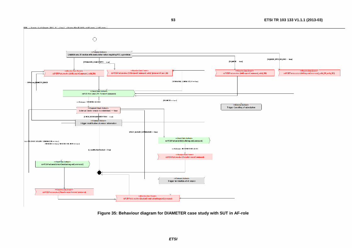
ETSI
ETSI TR 103 133 V1.1.1 (2013-03)93
Figure 35: Behaviour diagram for DIAMETER case study with SUT in AF-role

ETSI
ETSI TR 103 133 V1.1.1 (2013-03)94
7.5.3 Generating test cases with FOKUS MD Tester for case study 3
The generation of test cases for this case study was performed along the same principles as for the other two case studies. A total of 68 test cases were generated using the built-in MDTester test generation engine with the maximal number of loops parameter set to a value of 5.
7.5.4 Evaluation
To evaluate the case study a traceability matrix was automatically generated with the MDTester tool.
The traceability matrix generated by the MDTester tool (see clause A.3.3)indicates that all test purposes defined in the original ETSI TSS and TP document are covered by the generated test cases. That is in itself no surprise, because those test purposes were modelled as so-calles test objectives in the model and used to guide the behaviour modelling process. Again, as described earlier on, the traceability relationship is created by attaching individual edges from the test activity diagram to one or several test objectives modelled previously.
Given that the data structures representing the messages exchanged in the DIAMETER protocol were specified in the data model and could be used to express the guarding expressions on the transitions in the diagram, a granularity of test case behaviour could be achieved, that is quite similar to that of TTCN-3 test cases relying on some lower-level reusable TTCN-3 library functions.
8 Evaluation of all case studies This clause contains resume on the case studies performed.
In all previously exposed case studies, two of which are concerned with standards of the real-life complexity, the main goals of modelling and test generation were successfully achieved. Namely, in each case a model was developed with the help of each of 4 tools used and each tool successfully generate a test suite for each system.
Moreover, evaluation of tests generated demonstrates that in all cases studies and for all tools the modelling perfomed is sufficient to get test suites of the quality close to the quality of the conformance test sutes manually developed. The worst coverage of test purposes was about 85 %, and coverage of requirements used in modelling is also always rather high.
In addition to the coverage of test purposes and standard requirements, the maintainability of the test suites generated along with their closeness to executable status were evaluated.
In all cases the test suites generated cannot be executed as is. They all require adapters for connection with a SUT, but also they often require additional development of some auxiliary functions, addition of processing defaults in test cases, and addition of processing data fields that are abstracted in models (this can be also done in adapters). Sometimes additional effort is needed to implement in the test suite correct work with time-related events.
From the maintainability viewpoint the produced test suites are well structured and accurately traced to requirement statements used in models, but may lack explanatory names of internal variables and functions (and sometimes even test cases themselves). The standard structure of preamble/main part/postabmle with correct processing of failures in a preamble into inconclusive verdicts is also not supported by all tools.
The case studies performed demonstrated that Model-Based Testing can be successfully used for development of conformance test suites. MBT tools provide more control on resulting test coverage, and the formal modelling itself serves as a validation of the standard requirements (a dozen of issues in GeoNetworking protocol specification are discovered during its modelling).
From the other side, use of MBT in standardization poses new challenges: the need to have deep expertise at the same time in the domain (protocol under consideration), modelling, and test development; and problems occurring from the fact that a conformance test suite, which is considered as a separately maintainable artefact in standardization, can now be generated from a model, which has not official status yet.

ETSI
ETSI TR 103 133 V1.1.1 (2013-03)95
Annex A: Detailed evaluation of case studies
A.1 Evaluation of case study 1: ATM academic example
A.1.1 ATM case study evaluation with Spec Explorer This clause provides further information about the application of Spec Explorer to the ATM academic example. Spec Explorer model and generated test cases can be found in the electronic annex B.
Table A.1 provides identifiers of transitions in the ATM statechart for further use.
Table A.1
N ID Transition 1 A Idle->Idle, invalid card 2 B Idle->Authentication, valid card 3 C Authentication ->Idle, incorrect pin 4 D Authentication-> ReadyForMoneyRequest, correct pin 5 E ReadyForMoneyRequest -> ReadyForMoneyRequest, invalid amount 6 F ReadyForMoneyRequest ->Idle, valid amount
Table A.2 shows how transitions are covered by the generated test suite.
Table A.2
TC01 TC02 TC03 TC04 TC05 TC06 TC07 TC08 TC09 TC10 TC11 TC12 TC13 TC14 A X B X X X X X X X X X X X X X C X X X D X X X X X X X X X X X X X E X X X X X X F X X X X X X X X X X X X X
Total number of situations 6 Number of covered situations 6 Percentage of situations covered 100,0 %

ETSI
ETSI TR 103 133 V1.1.1 (2013-03)96
Table A.3 shows coverage of pairs of consecutive transitions in the ATM statechart by the generated test suite.
Table A.3
TC01 TC02 TC03 TC04 TC05 TC06 TC07 TC08 TC09 TC10 TC11 TC12 TC13 TC14 AA AB BC X X X BD X X X X X X X X X X X X X CA CB X X X DE X X X X X X DF X X X X X X X X X EE X X EF X X X X X X FA FB X X X X X X X X X X X X X
Total number of situations 12 Number of covered situations 8 Percentage of situations covered 66,7 %
Table A.4 shows coverage of basic paths in the ATM statechart by the generated test suite. A basic path is a path on a graph, which may contain only one repeating state and cannot be extended by adding transitions to its end with keeping this property. Basic paths starting in non-initial state should not be extensible by adding transitions to their beginning.
Table A.4
TC01 TC02 TC03 TC04 TC05 TC06 TC07 TC08 TC09 TC10 TC11 TC12 TC13 TC14 A X
BC X X X BDE X X X X X X BDF X X X X X X X X X CA CB X X X
DFA DFB X X X X X X X X FBC X FBD X X X X X X X X X X
Total number of situations 10 Number of covered situations 8 Percentage of situations covered 80,0 %
A.1.2 ATM case study evaluation with MDTester This clause provides the traceability matrix generated by MDTester for the ATM case study. MDTester model and generated test cases can be found in the electronic annex B.

ETSI
ETSI TR 103 133 V1.1.1 (2013-03) 97
Table A.5: Traceability matrix of TPs from the ATM Use Case
Test case TP_ATM_001 TP_ATM_002 TP_ATM_003 TP_ATM_004 TP_ATM_005 TP_ATM_006 TP_ATM_007
ATM_Scenario_4_Test case_1 X
ATM_Scenario_4_Test case_2 X X
ATM_Scenario_4_Test case_2_1 X X
ATM_Scenario_4_Test case_2_2 X X
ATM_Scenario_4_Test case_2_3 X X
ATM_Scenario_4_Test case_3 X X X X X
ATM_Scenario_4_Test case_3_1 X X X X X
ATM_Scenario_4_Test case_3_2 X X X X X
ATM_Scenario_4_Test case_3_3 X X X X X
ATM_Scenario_4_Test case_4 X X X X X
ATM_Scenario_4_Test case_4_1 X X X X X
ATM_Scenario_4_Test case_4_2 X X X X X
ATM_Scenario_4_Test case_4_3 X X X X X
ATM_Scenario_4_Test case_5 X X X
ATM_Scenario_4_Test case_5_1 X X X
ATM_Scenario_4_Test case_5_2 X X X
ATM_Scenario_4_Test case_5_3 X X X
ATM_Scenario_4_Test case_6 X X X X X
ATM_Scenario_4_Test case_6_1 X X X X X
ATM_Scenario_4_Test case_6_2 X X X X X
ATM_Scenario_4_Test case_6_3 X X X X X
ATM_Scenario_4_Test case_7 X X X X X
ATM_Scenario_4_Test case_7_1 X X X X X
ATM_Scenario_4_Test case_7_2 X X X X X
ATM_Scenario_4_Test case_7_3 X X X X X
ATM_Scenario_4_Test case_8 X X X
ATM_Scenario_4_Test case_8_1 X X X
ATM_Scenario_4_Test case_8_2 X X X
ATM_Scenario_4_Test case_8_3 X X X
ATM_Scenario_4_Test case_9 X X X X X
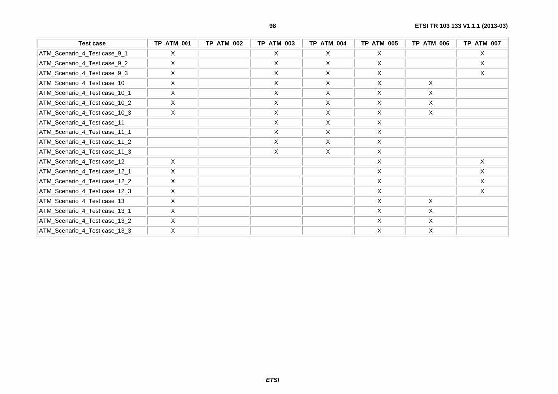
ETSI
ETSI TR 103 133 V1.1.1 (2013-03) 98
Test case TP_ATM_001 TP_ATM_002 TP_ATM_003 TP_ATM_004 TP_ATM_005 TP_ATM_006 TP_ATM_007
ATM_Scenario_4_Test case_9_1 X X X X X
ATM_Scenario_4_Test case_9_2 X X X X X
ATM_Scenario_4_Test case_9_3 X X X X X
ATM_Scenario_4_Test case_10 X X X X X
ATM_Scenario_4_Test case_10_1 X X X X X
ATM_Scenario_4_Test case_10_2 X X X X X
ATM_Scenario_4_Test case_10_3 X X X X X
ATM_Scenario_4_Test case_11 X X X
ATM_Scenario_4_Test case_11_1 X X X
ATM_Scenario_4_Test case_11_2 X X X
ATM_Scenario_4_Test case_11_3 X X X
ATM_Scenario_4_Test case_12 X X X
ATM_Scenario_4_Test case_12_1 X X X
ATM_Scenario_4_Test case_12_2 X X X
ATM_Scenario_4_Test case_12_3 X X X
ATM_Scenario_4_Test case_13 X X X
ATM_Scenario_4_Test case_13_1 X X X
ATM_Scenario_4_Test case_13_2 X X X
ATM_Scenario_4_Test case_13_3 X X X

ETSI
ETSI TR 103 133 V1.1.1 (2013-03) 99
A.2 Evaluation of case study 2: ITS location services
A.2.1 ITS location services case study evaluation with Spec Explorer
This clause provides further information about the application of Spec Explorer to the ITS location services case study. Spec Explorer model and generated test cases can be found in the electronic annex B.
Table A.6 contains full list of requirement statements essential for branching of external event processing.
Table A.6
ID Identification on flowcharts Description R01 GeoUnicast/9.2.4.2.2/1.a Destination address is known; LS pending for destination address; pushing
data into LS buffer. R02 GeoUnicast/irrelevant Destination address is known; LS finished; sending GEO-UNICAST packet. R03 GeoUnicast/9.2.4.2.2/2 Destination address is not known. R04 GeoUnicast/9.3.5.2/5 There are neighbours; broadcasting LS-REQUEST packet. R05 GeoUnicast/9.3.5.2/2 There are no neighbours; pushing LS-REQUEST into BC buffer. R06 LSTimer/9.2.4.2.3/3 Retransmission counter reaches maximum; stopping LS. R07 LSTimer/9.2.4.2.3/2 Retransmission counter less than maximum. R08 LSTimer/9.3.5.2/5 There are neighbours; broadcasting LS-REQUEST packet. R09 LSTimer/9.3.5.2/2 There are no neighbours; pushing LS-REQUEST into BC buffer. R10 LSRequest/9.3.3/3.a LS is pending for sender of LS-REQUEST. R11 LSRequest/9.3.3/3.b UC buffer for sender of LS-REQUEST is non-empty. R12 LSRequest/9.3.3/3.c BC buffer for sender of LS-REQUEST is non-empty. R13 LSRequest/Annex A (duplicate) LS-REQUEST is duplicate. R14 LSRequest/Annex A (non-duplicate) LS-REQUEST is not duplicate. R15 LSRequest/9.2.4.4,9.3.5.3/4 Source and sender of LS-REQUEST are different. R16 LSRequest/9.2.4.4/5 LS-REQUEST seeks this unit. R17 LSRequest/9.2.4.3->9.3.5.3 LS-REQUEST seeks another unit. R18 LSRequest/9.3.5.3/6,9.3.4.3/9 Hop limit of LS-REQUEST becomes zero. R19 LSReply/9.3.3/3.a LS is pending for sender of LS-REPLY. R20 LSReply/9.3.3/3.b UC buffer for sender of LS-REPLY is non-empty. R21 LSReply/9.3.3/3.c BC buffer for sender of LS-REPLY is non-empty. R22 LSReply/Annex A (duplicate) LS-REPLY is duplicate. R23 LSReply/Annex A (non-duplicate) LS-REPLY is not duplicate. R24 LSReply/9.2.4.2.4,9.3.4.3/4 Source and sender of LS-REPLY are different. R25 LSReply/9.2.4.2.4,9.3.4.3/5.a LS is pending for source of LS-REPLY. R26 LSReply/9.2.4.2.4,9.3.4.3/5.b UC buffer for source of LS-REPLY is non-empty. R27 LSReply/9.2.4.2.4/8-9 LS-REPLY is intended for this unit. R28 LSReply/9.2.4.3->9.3.5.3 LS-REPLY is intended for another unit. R29 LSReply/9.3.5.3/6,9.3.4.3/9 Hop limit of LS-REPLY becomes zero. R30 LSReply/9.3.4.3/8->B3 Update of LS-REPLY destination PV is needed. R31 LSReply/9.3.4.3/13 There exists a neighbour more close to destination. R32 LSReply/9.3.4.3/11 There are no neighbours more close to destination.

ETSI
ETSI TR 103 133 V1.1.1 (2013-03) 100
Table A.7 shows coverage of the requirements statements presented above by the tests generated.
Table A.7
R01 R02 R03 R04 R05 R06 R07 R08 R09 R10 R11 R12 R13 R14 R15 R16 R17 R18 R19 R20 TC01 X X TC02 X X X TC03 X X TC04 X X X TC05 X X X X X X X X X TC06 X X X X X X X X X TC07 X X X X X X X X X TC08 X X TC09 X X TC10 X X TC11 X X X X TC12 X X X X X TC13 X X X X X TC14 X X X TC15 X TC16 X X X TC17 X X X X X X TC18 X X X X X TC19 X X X X X TC20 X X X TC21 X X TC22 X X TC23 X X X X X TC24 X X X X X X X X X TC25 X X X X X X X X X TC26 X X X X X X X X X TC27 X X X X X TC28 X X X X X X X TC29 X TC30 X X X X TC31 X X TC32 X X X TC33 X X TC34 X X X X X X TC35 X TC36 X TC37 X X X X X X TC38 X TC39 X X TC40 X X X X X X

ETSI
ETSI TR 103 133 V1.1.1 (2013-03) 101
R21 R22 R23 R24 R25 R26 R27 R28 R29 R30 R31 R32 TC01 X X X X TC02 X X X TC03 X X X X X TC04 X X X X TC05 TC06 TC07 TC08 X X X X X TC09 X X X X X TC10 X X X X X X X TC11 X X X TC12 X X X TC13 X X X X TC14 TC15 X X X X TC16 X X X X X TC17 TC18 X X X X TC19 TC20 X X X X TC21 X X X X X TC22 X X X X X TC23 X X X X TC24 TC25 TC26 TC27 TC28 TC29 X X X X X TC30 X X X X TC31 X X X X TC32 X X X TC33 X X X X TC34 X X X X TC35 X X X X TC36 X X X X X TC37 X X X X TC38 X X X X X X TC39 X X X X X TC40
Total number of situations 32 Number of covered situations 31 Percentage of situations covered 96,88 %
A.2.2 ITS location services case study evaluation with Conformiq Designer™
This clause provides further information about the application of Conformiq Designer™ to the ITS location services case study. Conformiq Designer™ model and generated test cases can be found in the electronic annex B.
The dependencies between test cases are automatically tracked when the test suite is generated using "OSI Methodology Support" and a Test Dependency Matrix is generated, which shows how the test cases depend on each other (see figure A.1).

ETSI
ETSI TR 103 133 V1.1.1 (2013-03) 102
Figure A.1: Test Case Dependency Matrix
Using the model described in clause 6.3.2 and setting the parameters of the test generator according to clause 6.3.3.2 a test suite consisting of 44 test cases is produced by the tool.
Again, the Traceability Matrix in figure A.2 shows how the Test Purposes are covered by the generated test cases:
Figure A.2: Test Purpose Coverage
There are some test cases that are differing from each other, but they are testing the same test purpose (see figure A.3). The reason for this is that the handler functions were implemented based on the standard and there were some branches that were marked with different "requirements". This leads to several test cases that are going deeper into the protocol behaviour than the Test Purposes. The first 4 test cases do not belong to any test purpose, they are containing the signalling to initialize the test configuration CF01.
Figure A.3: Requirement Coverage

ETSI
ETSI TR 103 133 V1.1.1 (2013-03) 103
The Test Dependency Matrix was generated in this case as well (see figure A.4).
Figure A.4: Test Case Dependency Matrix
A.2.3 ITS location services case study evaluation with sepp.med MBTsuite
This clause presents how the ITS test purposes are covered by the test cases that were generate by the MBTsuite tool.
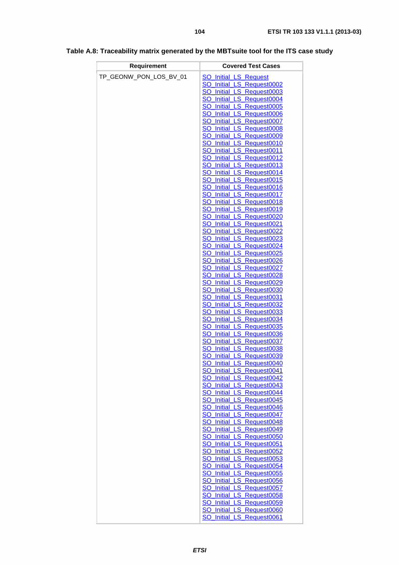
ETSI
ETSI TR 103 133 V1.1.1 (2013-03) 104
Table A.8: Traceability matrix generated by the MBTsuite tool for the ITS case study
Requirement Covered Test Cases
TP_GEONW_PON_LOS_BV_01 SO_Initial_LS_Request SO_Initial_LS_Request0002 SO_Initial_LS_Request0003 SO_Initial_LS_Request0004 SO_Initial_LS_Request0005 SO_Initial_LS_Request0006 SO_Initial_LS_Request0007 SO_Initial_LS_Request0008 SO_Initial_LS_Request0009 SO_Initial_LS_Request0010 SO_Initial_LS_Request0011 SO_Initial_LS_Request0012 SO_Initial_LS_Request0013 SO_Initial_LS_Request0014 SO_Initial_LS_Request0015 SO_Initial_LS_Request0016 SO_Initial_LS_Request0017 SO_Initial_LS_Request0018 SO_Initial_LS_Request0019 SO_Initial_LS_Request0020 SO_Initial_LS_Request0021 SO_Initial_LS_Request0022 SO_Initial_LS_Request0023 SO_Initial_LS_Request0024 SO_Initial_LS_Request0025 SO_Initial_LS_Request0026 SO_Initial_LS_Request0027 SO_Initial_LS_Request0028 SO_Initial_LS_Request0029 SO_Initial_LS_Request0030 SO_Initial_LS_Request0031 SO_Initial_LS_Request0032 SO_Initial_LS_Request0033 SO_Initial_LS_Request0034 SO_Initial_LS_Request0035 SO_Initial_LS_Request0036 SO_Initial_LS_Request0037 SO_Initial_LS_Request0038 SO_Initial_LS_Request0039 SO_Initial_LS_Request0040 SO_Initial_LS_Request0041 SO_Initial_LS_Request0042 SO_Initial_LS_Request0043 SO_Initial_LS_Request0044 SO_Initial_LS_Request0045 SO_Initial_LS_Request0046 SO_Initial_LS_Request0047 SO_Initial_LS_Request0048 SO_Initial_LS_Request0049 SO_Initial_LS_Request0050 SO_Initial_LS_Request0051 SO_Initial_LS_Request0052 SO_Initial_LS_Request0053 SO_Initial_LS_Request0054 SO_Initial_LS_Request0055 SO_Initial_LS_Request0056 SO_Initial_LS_Request0057 SO_Initial_LS_Request0058 SO_Initial_LS_Request0059 SO_Initial_LS_Request0060 SO_Initial_LS_Request0061

ETSI
ETSI TR 103 133 V1.1.1 (2013-03) 105
Requirement Covered Test Cases
SO_Initial_LS_Request0062 SO_Initial_LS_Request0063 SO_Initial_LS_Request0064 SO_Initial_LS_Request0065 SO_Initial_LS_Request0066 SO_Initial_LS_Request0067 SO_Initial_LS_Request0068 SO_Initial_LS_Request0069 SO_Initial_LS_Request0070 SO_Initial_LS_Request0071 SO_Initial_LS_Request0072 SO_Initial_LS_Request0073 SO_Initial_LS_Request0074 SO_Initial_LS_Request0075 SO_Initial_LS_Request0076 SO_Initial_LS_Request0077 SO_Initial_LS_Request0078 SO_Initial_LS_Request0079 SO_Initial_LS_Request0080 SO_Initial_LS_Request0081 SO_Initial_LS_Request0082 SO_Initial_LS_Request0083 SO_Initial_LS_Request0084 SO_Initial_LS_Request0085 SO_Initial_LS_Request0086 SO_Initial_LS_Request0087 SO_Initial_LS_Request0088 SO_Initial_LS_Request0089 SO_Initial_LS_Request0090 SO_Initial_LS_Request0091 SO_Initial_LS_Request0092 SO_Initial_LS_Request0093 SO_Initial_LS_Request0094 SO_Initial_LS_Request0095 SO_Initial_LS_Request0096 SO_Initial_LS_Request0097 SO_Initial_LS_Request0098 SO_Initial_LS_Request0099 SO_Initial_LS_Request0100 SO_Initial_LS_Request0101 SO_Initial_LS_Request0102 SO_Initial_LS_Request0103 SO_Initial_LS_Request0104 SO_Initial_LS_Request0105 SO_Initial_LS_Request0106 SO_Initial_LS_Request0107 SO_Initial_LS_Request0108 SO_Initial_LS_Request0109 SO_Initial_LS_Request0110 SO_Initial_LS_Request0111 SO_Initial_LS_Request0112 SO_Initial_LS_Request0113 SO_Initial_LS_Request0114 SO_Initial_LS_Request0115 SO_Initial_LS_Request0116 SO_Initial_LS_Request0117 SO_Initial_LS_Request0118 SO_Initial_LS_Request0119 SO_Initial_LS_Request0120 SO_Initial_LS_Request0121 SO_Initial_LS_Request0122 SO_Initial_LS_Request0123 SO_Initial_LS_Request0124

ETSI
ETSI TR 103 133 V1.1.1 (2013-03) 106
Requirement Covered Test Cases
SO_Initial_LS_Request0125 SO_Initial_LS_Request0126 SO_Initial_LS_Request0127 SO_Initial_LS_Request0128 SO_Initial_LS_Request0129 SO_Initial_LS_Request0130 SO_Initial_LS_Request0131 SO_Initial_LS_Request0132 SO_Initial_LS_Request0133 SO_Initial_LS_Request0134 SO_Initial_LS_Request0135 SO_Initial_LS_Request0136 SO_Initial_LS_Request0137 SO_Initial_LS_Request0138
TP_GEONW_PON_LOS_BV_02 SO_Initial_LS_Request0002 SO_Initial_LS_Request0003 SO_Initial_LS_Request0004 SO_Initial_LS_Request0005 SO_Initial_LS_Request0006 SO_Initial_LS_Request0007 SO_Initial_LS_Request0008 SO_Initial_LS_Request0009 SO_Initial_LS_Request0010 SO_Initial_LS_Request0011 SO_Initial_LS_Request0012 SO_Initial_LS_Request0013 SO_Initial_LS_Request0014 SO_Initial_LS_Request0015 SO_Initial_LS_Request0016 SO_Initial_LS_Request0017 SO_Initial_LS_Request0018 SO_Initial_LS_Request0019 SO_Initial_LS_Request0020 SO_Initial_LS_Request0021 SO_Initial_LS_Request0022 SO_Initial_LS_Request0023 SO_Initial_LS_Request0024 SO_Initial_LS_Request0025 SO_Initial_LS_Request0026 SO_Initial_LS_Request0027 SO_Initial_LS_Request0028 SO_Initial_LS_Request0029 SO_Initial_LS_Request0030 SO_Initial_LS_Request0031 SO_Initial_LS_Request0033 SO_Initial_LS_Request0034 SO_Initial_LS_Request0035 SO_Initial_LS_Request0036 SO_Initial_LS_Request0037 SO_Initial_LS_Request0038 SO_Initial_LS_Request0039 SO_Initial_LS_Request0040 SO_Initial_LS_Request0041 SO_Initial_LS_Request0042 SO_Initial_LS_Request0043 SO_Initial_LS_Request0044 SO_Initial_LS_Request0045 SO_Initial_LS_Request0046 SO_Initial_LS_Request0047 SO_Initial_LS_Request0048 SO_Initial_LS_Request0049 SO_Initial_LS_Request0050

ETSI
ETSI TR 103 133 V1.1.1 (2013-03) 107
Requirement Covered Test Cases
SO_Initial_LS_Request0051 SO_Initial_LS_Request0052 SO_Initial_LS_Request0053 SO_Initial_LS_Request0054 SO_Initial_LS_Request0055 SO_Initial_LS_Request0056 SO_Initial_LS_Request0057 SO_Initial_LS_Request0058 SO_Initial_LS_Request0059 SO_Initial_LS_Request0060 SO_Initial_LS_Request0061 SO_Initial_LS_Request0062 SO_Initial_LS_Request0063 SO_Initial_LS_Request0064 SO_Initial_LS_Request0065 SO_Initial_LS_Request0066 SO_Initial_LS_Request0067 SO_Initial_LS_Request0068 SO_Initial_LS_Request0070 SO_Initial_LS_Request0072 SO_Initial_LS_Request0073 SO_Initial_LS_Request0075 SO_Initial_LS_Request0077 SO_Initial_LS_Request0078 SO_Initial_LS_Request0079 SO_Initial_LS_Request0080 SO_Initial_LS_Request0081 SO_Initial_LS_Request0082 SO_Initial_LS_Request0083 SO_Initial_LS_Request0084 SO_Initial_LS_Request0086 SO_Initial_LS_Request0088 SO_Initial_LS_Request0089 SO_Initial_LS_Request0090 SO_Initial_LS_Request0091 SO_Initial_LS_Request0092 SO_Initial_LS_Request0093 SO_Initial_LS_Request0094 SO_Initial_LS_Request0095 SO_Initial_LS_Request0096 SO_Initial_LS_Request0097 SO_Initial_LS_Request0098 SO_Initial_LS_Request0099 SO_Initial_LS_Request0101 SO_Initial_LS_Request0102 SO_Initial_LS_Request0103 SO_Initial_LS_Request0104 SO_Initial_LS_Request0105 SO_Initial_LS_Request0106 SO_Initial_LS_Request0107 SO_Initial_LS_Request0108 SO_Initial_LS_Request0109 SO_Initial_LS_Request0110 SO_Initial_LS_Request0111 SO_Initial_LS_Request0113 SO_Initial_LS_Request0114 SO_Initial_LS_Request0115 SO_Initial_LS_Request0116 SO_Initial_LS_Request0117 SO_Initial_LS_Request0118 SO_Initial_LS_Request0119 SO_Initial_LS_Request0120 SO_Initial_LS_Request0121

ETSI
ETSI TR 103 133 V1.1.1 (2013-03) 108
Requirement Covered Test Cases
SO_Initial_LS_Request0122 SO_Initial_LS_Request0123 SO_Initial_LS_Request0124 SO_Initial_LS_Request0125 SO_Initial_LS_Request0128 SO_Initial_LS_Request0130 SO_Initial_LS_Request0131 SO_Initial_LS_Request0132 SO_Initial_LS_Request0133 SO_Initial_LS_Request0134 SO_Initial_LS_Request0135 SO_Initial_LS_Request0136 SO_Initial_LS_Request0137 SO_Initial_LS_Request0138
TP_GEONW_PON_LOS_BV_03 SO_Initial_LS_Request SO_Initial_LS_Request0032 SO_Initial_LS_Request0069 SO_Initial_LS_Request0071 SO_Initial_LS_Request0074 SO_Initial_LS_Request0100 SO_Initial_LS_Request0112 SO_Initial_LS_Request0126 SO_Initial_LS_Request0127 SO_Initial_LS_Request0129
TP_GEONW_PON_LOS_BV_04 SO_Initial_LS_Request SO_Initial_LS_Request0032 SO_Initial_LS_Request0069 SO_Initial_LS_Request0071 SO_Initial_LS_Request0074 SO_Initial_LS_Request0100 SO_Initial_LS_Request0112 SO_Initial_LS_Request0126 SO_Initial_LS_Request0127 SO_Initial_LS_Request0129
TP_GEONW_PON_LOS_BV_05 SO_Initial_LS_Request0002 SO_Initial_LS_Request0003 SO_Initial_LS_Request0004 SO_Initial_LS_Request0005 SO_Initial_LS_Request0006 SO_Initial_LS_Request0007 SO_Initial_LS_Request0008 SO_Initial_LS_Request0009 SO_Initial_LS_Request0010 SO_Initial_LS_Request0011 SO_Initial_LS_Request0012 SO_Initial_LS_Request0013 SO_Initial_LS_Request0014 SO_Initial_LS_Request0015 SO_Initial_LS_Request0016 SO_Initial_LS_Request0017 SO_Initial_LS_Request0018 SO_Initial_LS_Request0019 SO_Initial_LS_Request0020 SO_Initial_LS_Request0021 SO_Initial_LS_Request0022 SO_Initial_LS_Request0023 SO_Initial_LS_Request0024 SO_Initial_LS_Request0025 SO_Initial_LS_Request0026 SO_Initial_LS_Request0027 SO_Initial_LS_Request0028

ETSI
ETSI TR 103 133 V1.1.1 (2013-03) 109
Requirement Covered Test Cases
SO_Initial_LS_Request0029 SO_Initial_LS_Request0030 SO_Initial_LS_Request0031 SO_Initial_LS_Request0033 SO_Initial_LS_Request0034 SO_Initial_LS_Request0035 SO_Initial_LS_Request0036 SO_Initial_LS_Request0037 SO_Initial_LS_Request0038 SO_Initial_LS_Request0039 SO_Initial_LS_Request0040 SO_Initial_LS_Request0041 SO_Initial_LS_Request0042 SO_Initial_LS_Request0043 SO_Initial_LS_Request0044 SO_Initial_LS_Request0045 SO_Initial_LS_Request0046 SO_Initial_LS_Request0047 SO_Initial_LS_Request0048 SO_Initial_LS_Request0049 SO_Initial_LS_Request0050 SO_Initial_LS_Request0051 SO_Initial_LS_Request0052 SO_Initial_LS_Request0053 SO_Initial_LS_Request0054 SO_Initial_LS_Request0055 SO_Initial_LS_Request0056 SO_Initial_LS_Request0057 SO_Initial_LS_Request0058 SO_Initial_LS_Request0059 SO_Initial_LS_Request0060 SO_Initial_LS_Request0061 SO_Initial_LS_Request0062 SO_Initial_LS_Request0063 SO_Initial_LS_Request0064 SO_Initial_LS_Request0065 SO_Initial_LS_Request0066 SO_Initial_LS_Request0070 SO_Initial_LS_Request0076 SO_Initial_LS_Request0083 SO_Initial_LS_Request0084 SO_Initial_LS_Request0085 SO_Initial_LS_Request0086 SO_Initial_LS_Request0087 SO_Initial_LS_Request0088 SO_Initial_LS_Request0089 SO_Initial_LS_Request0090 SO_Initial_LS_Request0091 SO_Initial_LS_Request0092 SO_Initial_LS_Request0093 SO_Initial_LS_Request0101 SO_Initial_LS_Request0102 SO_Initial_LS_Request0103 SO_Initial_LS_Request0104 SO_Initial_LS_Request0105 SO_Initial_LS_Request0106 SO_Initial_LS_Request0107 SO_Initial_LS_Request0108 SO_Initial_LS_Request0109 SO_Initial_LS_Request0110 SO_Initial_LS_Request0111 SO_Initial_LS_Request0113 SO_Initial_LS_Request0114

ETSI
ETSI TR 103 133 V1.1.1 (2013-03) 110
Requirement Covered Test Cases
SO_Initial_LS_Request0115 SO_Initial_LS_Request0116 SO_Initial_LS_Request0117 SO_Initial_LS_Request0118 SO_Initial_LS_Request0119 SO_Initial_LS_Request0120 SO_Initial_LS_Request0121 SO_Initial_LS_Request0122 SO_Initial_LS_Request0123 SO_Initial_LS_Request0124 SO_Initial_LS_Request0133 SO_Initial_LS_Request0134 SO_Initial_LS_Request0135
TP_GEONW_PON_LOS_BV_06 SO_Initial_LS_Request0007 SO_Initial_LS_Request0008 SO_Initial_LS_Request0009 SO_Initial_LS_Request0017 SO_Initial_LS_Request0034 SO_Initial_LS_Request0035 SO_Initial_LS_Request0036 SO_Initial_LS_Request0041 SO_Initial_LS_Request0051 SO_Initial_LS_Request0052 SO_Initial_LS_Request0053 SO_Initial_LS_Request0054 SO_Initial_LS_Request0055 SO_Initial_LS_Request0058 SO_Initial_LS_Request0059 SO_Initial_LS_Request0060 SO_Initial_LS_Request0063 SO_Initial_LS_Request0067 SO_Initial_LS_Request0068 SO_Initial_LS_Request0069 SO_Initial_LS_Request0070 SO_Initial_LS_Request0071 SO_Initial_LS_Request0072 SO_Initial_LS_Request0073 SO_Initial_LS_Request0074 SO_Initial_LS_Request0075 SO_Initial_LS_Request0076 SO_Initial_LS_Request0077 SO_Initial_LS_Request0078 SO_Initial_LS_Request0079 SO_Initial_LS_Request0080 SO_Initial_LS_Request0081 SO_Initial_LS_Request0082 SO_Initial_LS_Request0083 SO_Initial_LS_Request0084 SO_Initial_LS_Request0085 SO_Initial_LS_Request0086 SO_Initial_LS_Request0087 SO_Initial_LS_Request0088 SO_Initial_LS_Request0089 SO_Initial_LS_Request0090 SO_Initial_LS_Request0091 SO_Initial_LS_Request0092 SO_Initial_LS_Request0093 SO_Initial_LS_Request0102 SO_Initial_LS_Request0113 SO_Initial_LS_Request0119 SO_Initial_LS_Request0120 SO_Initial_LS_Request0122

ETSI
ETSI TR 103 133 V1.1.1 (2013-03) 111
Requirement Covered Test Cases
SO_Initial_LS_Request0125 SO_Initial_LS_Request0126 SO_Initial_LS_Request0127 SO_Initial_LS_Request0128 SO_Initial_LS_Request0129 SO_Initial_LS_Request0130 SO_Initial_LS_Request0131 SO_Initial_LS_Request0132 SO_Initial_LS_Request0133 SO_Initial_LS_Request0134 SO_Initial_LS_Request0135
TP_GEONW_PON_LOS_BV_07 SO_Initial_LS_Request0007 SO_Initial_LS_Request0008 SO_Initial_LS_Request0009 SO_Initial_LS_Request0017 SO_Initial_LS_Request0034 SO_Initial_LS_Request0035 SO_Initial_LS_Request0036 SO_Initial_LS_Request0041 SO_Initial_LS_Request0051 SO_Initial_LS_Request0052 SO_Initial_LS_Request0053 SO_Initial_LS_Request0054 SO_Initial_LS_Request0055 SO_Initial_LS_Request0058 SO_Initial_LS_Request0059 SO_Initial_LS_Request0060 SO_Initial_LS_Request0063 SO_Initial_LS_Request0067 SO_Initial_LS_Request0068 SO_Initial_LS_Request0069 SO_Initial_LS_Request0070 SO_Initial_LS_Request0071 SO_Initial_LS_Request0072 SO_Initial_LS_Request0073 SO_Initial_LS_Request0074 SO_Initial_LS_Request0075 SO_Initial_LS_Request0076 SO_Initial_LS_Request0077 SO_Initial_LS_Request0078 SO_Initial_LS_Request0079 SO_Initial_LS_Request0080 SO_Initial_LS_Request0081 SO_Initial_LS_Request0082 SO_Initial_LS_Request0083 SO_Initial_LS_Request0084 SO_Initial_LS_Request0085 SO_Initial_LS_Request0086 SO_Initial_LS_Request0087 SO_Initial_LS_Request0088 SO_Initial_LS_Request0089 SO_Initial_LS_Request0090 SO_Initial_LS_Request0091 SO_Initial_LS_Request0092 SO_Initial_LS_Request0093 SO_Initial_LS_Request0102 SO_Initial_LS_Request0113 SO_Initial_LS_Request0119 SO_Initial_LS_Request0120 SO_Initial_LS_Request0122 SO_Initial_LS_Request0125 SO_Initial_LS_Request0126

ETSI
ETSI TR 103 133 V1.1.1 (2013-03) 112
Requirement Covered Test Cases
SO_Initial_LS_Request0127 SO_Initial_LS_Request0128 SO_Initial_LS_Request0129 SO_Initial_LS_Request0130 SO_Initial_LS_Request0131 SO_Initial_LS_Request0132 SO_Initial_LS_Request0133 SO_Initial_LS_Request0134 SO_Initial_LS_Request0135
TP_GEONW_PON_LOS_BV_08 SO_Initial_LS_Request SO_Initial_LS_Request0032 SO_Initial_LS_Request0069 SO_Initial_LS_Request0071 SO_Initial_LS_Request0074 SO_Initial_LS_Request0100 SO_Initial_LS_Request0112 SO_Initial_LS_Request0126 SO_Initial_LS_Request0127 SO_Initial_LS_Request0129
TP_GEONW_PON_LOS_BV_09 SO_Initial_LS_Request0002 SO_Initial_LS_Request0003 SO_Initial_LS_Request0004 SO_Initial_LS_Request0005 SO_Initial_LS_Request0006 SO_Initial_LS_Request0007 SO_Initial_LS_Request0008 SO_Initial_LS_Request0009 SO_Initial_LS_Request0010 SO_Initial_LS_Request0011 SO_Initial_LS_Request0012 SO_Initial_LS_Request0013 SO_Initial_LS_Request0014 SO_Initial_LS_Request0015 SO_Initial_LS_Request0016 SO_Initial_LS_Request0017 SO_Initial_LS_Request0018 SO_Initial_LS_Request0019 SO_Initial_LS_Request0020 SO_Initial_LS_Request0021 SO_Initial_LS_Request0022 SO_Initial_LS_Request0023 SO_Initial_LS_Request0024 SO_Initial_LS_Request0025 SO_Initial_LS_Request0026 SO_Initial_LS_Request0027 SO_Initial_LS_Request0028 SO_Initial_LS_Request0029 SO_Initial_LS_Request0030 SO_Initial_LS_Request0031 SO_Initial_LS_Request0033 SO_Initial_LS_Request0034 SO_Initial_LS_Request0035 SO_Initial_LS_Request0036 SO_Initial_LS_Request0037 SO_Initial_LS_Request0038 SO_Initial_LS_Request0039 SO_Initial_LS_Request0040 SO_Initial_LS_Request0041 SO_Initial_LS_Request0042 SO_Initial_LS_Request0043 SO_Initial_LS_Request0044

ETSI
ETSI TR 103 133 V1.1.1 (2013-03) 113
Requirement Covered Test Cases
SO_Initial_LS_Request0045 SO_Initial_LS_Request0046 SO_Initial_LS_Request0047 SO_Initial_LS_Request0048 SO_Initial_LS_Request0049 SO_Initial_LS_Request0050 SO_Initial_LS_Request0051 SO_Initial_LS_Request0052 SO_Initial_LS_Request0053 SO_Initial_LS_Request0054 SO_Initial_LS_Request0055 SO_Initial_LS_Request0056 SO_Initial_LS_Request0057 SO_Initial_LS_Request0058 SO_Initial_LS_Request0059 SO_Initial_LS_Request0060 SO_Initial_LS_Request0061 SO_Initial_LS_Request0062 SO_Initial_LS_Request0063 SO_Initial_LS_Request0064 SO_Initial_LS_Request0065 SO_Initial_LS_Request0066 SO_Initial_LS_Request0070 SO_Initial_LS_Request0076 SO_Initial_LS_Request0083 SO_Initial_LS_Request0084 SO_Initial_LS_Request0085 SO_Initial_LS_Request0086 SO_Initial_LS_Request0087 SO_Initial_LS_Request0088 SO_Initial_LS_Request0089 SO_Initial_LS_Request0090 SO_Initial_LS_Request0091 SO_Initial_LS_Request0092 SO_Initial_LS_Request0093 SO_Initial_LS_Request0101 SO_Initial_LS_Request0102 SO_Initial_LS_Request0103 SO_Initial_LS_Request0104 SO_Initial_LS_Request0105 SO_Initial_LS_Request0106 SO_Initial_LS_Request0107 SO_Initial_LS_Request0108 SO_Initial_LS_Request0109 SO_Initial_LS_Request0110 SO_Initial_LS_Request0111 SO_Initial_LS_Request0113 SO_Initial_LS_Request0114 SO_Initial_LS_Request0115 SO_Initial_LS_Request0116 SO_Initial_LS_Request0117 SO_Initial_LS_Request0118 SO_Initial_LS_Request0119 SO_Initial_LS_Request0120 SO_Initial_LS_Request0121 SO_Initial_LS_Request0122 SO_Initial_LS_Request0123 SO_Initial_LS_Request0124 SO_Initial_LS_Request0133 SO_Initial_LS_Request0134 SO_Initial_LS_Request0135
TP_GEONW_PON_LOS_BV_10 SO_Initial_LS_Request0004

ETSI
ETSI TR 103 133 V1.1.1 (2013-03) 114
Requirement Covered Test Cases
SO_Initial_LS_Request0008 SO_Initial_LS_Request0011 SO_Initial_LS_Request0013 SO_Initial_LS_Request0015 SO_Initial_LS_Request0019 SO_Initial_LS_Request0021 SO_Initial_LS_Request0023 SO_Initial_LS_Request0026 SO_Initial_LS_Request0028 SO_Initial_LS_Request0031 SO_Initial_LS_Request0035 SO_Initial_LS_Request0038 SO_Initial_LS_Request0040 SO_Initial_LS_Request0043 SO_Initial_LS_Request0045 SO_Initial_LS_Request0048 SO_Initial_LS_Request0052 SO_Initial_LS_Request0055 SO_Initial_LS_Request0057 SO_Initial_LS_Request0059 SO_Initial_LS_Request0062 SO_Initial_LS_Request0065 SO_Initial_LS_Request0068 SO_Initial_LS_Request0073 SO_Initial_LS_Request0078 SO_Initial_LS_Request0080 SO_Initial_LS_Request0082 SO_Initial_LS_Request0084 SO_Initial_LS_Request0089 SO_Initial_LS_Request0092 SO_Initial_LS_Request0095 SO_Initial_LS_Request0097 SO_Initial_LS_Request0099 SO_Initial_LS_Request0100 SO_Initial_LS_Request0101 SO_Initial_LS_Request0102 SO_Initial_LS_Request0103 SO_Initial_LS_Request0104 SO_Initial_LS_Request0105 SO_Initial_LS_Request0106 SO_Initial_LS_Request0107 SO_Initial_LS_Request0108 SO_Initial_LS_Request0109 SO_Initial_LS_Request0110 SO_Initial_LS_Request0111 SO_Initial_LS_Request0112 SO_Initial_LS_Request0113 SO_Initial_LS_Request0114 SO_Initial_LS_Request0115 SO_Initial_LS_Request0116 SO_Initial_LS_Request0117 SO_Initial_LS_Request0118 SO_Initial_LS_Request0119 SO_Initial_LS_Request0120 SO_Initial_LS_Request0121 SO_Initial_LS_Request0122 SO_Initial_LS_Request0123 SO_Initial_LS_Request0124 SO_Initial_LS_Request0125 SO_Initial_LS_Request0126 SO_Initial_LS_Request0127 SO_Initial_LS_Request0128 SO_Initial_LS_Request0129

ETSI
ETSI TR 103 133 V1.1.1 (2013-03) 115
Requirement Covered Test Cases
SO_Initial_LS_Request0130 SO_Initial_LS_Request0131 SO_Initial_LS_Request0132 SO_Initial_LS_Request0133 SO_Initial_LS_Request0134 SO_Initial_LS_Request0135 SO_Initial_LS_Request0136 SO_Initial_LS_Request0137 SO_Initial_LS_Request0138
A.3 Evaluation of case study 3: Diameter
A.3.1 Diameter case study evaluation with Spec Explorer This clause provides further information about the application of Spec Explorer to the Diameter case study. Spec Explorer model and generated test cases can be found in the electronic annex B.
Table A.9 shows coverage of branching requirements statements by the tests generated for AF unit. Only the requirements related with AF unit behaviour — R01-R14 — are considered.

ETSI
ETSI TR 103 133 V1.1.1 (2013-03) 116
Table A.9
R01 R02 R03 R04 R05 R06 R07 R08 R09 R10 R11 R12 R13 R14 TC01 X X X X X TC02 X X X X X X TC03 X X X X X TC04 X X X X TC05 X X X X X X TC06 X X X X X TC07 X X X X TC08 X X X X X TC09 X X X X TC10 X X X X X TC11 X X X X X X TC12 X X X X X TC13 X X X X X TC14 X X X X X TC15 X X X X X TC16 X X X X X TC17 X X X X X TC18 X X X X X TC19 X X X X X TC20 X X X X X X TC21 X X X X TC22 X X X X X TC23 X X X X X TC24 X X X X X X TC25 X X X X TC26 X X X X X TC27 X X X X X TC28 X X X X X TC29 X X X X X TC30 X X X X X TC31 X X X X X TC32 X X X X X TC33 X X X X X TC34 X X X X X TC35 X X X X X Total number of situations 14 Number of covered situations 14 Percentage of situations covered 100 %

ETSI
ETSI TR 103 133 V1.1.1 (2013-03) 117
Table A.10 shows coverage of branching requirements statements by the tests generated for PCRF unit. Only the requirements related with PCRF unit behaviour — R15-R35 — are considered.
Table A.10
R15 R16 R17 R18 R19 R20 R21 R22 R23 R24 R25 R26 R27 R28 R29 R30 R31 R32 R33 R34 R35 TC01 X X TC02 X X X X X X TC03 X X X X X TC04 X X X X X TC05 X X X TC06 X X X TC07 X X X X X TC08 X X X X X X X TC09 X X X X TC10 X X X X X TC11 X X X X X X TC12 X X X X X TC13 X X X TC14 X X X X TC15 X X X X X TC16 X X X X TC17 X X X X X X X TC18 X X X X X TC19 X X X X X X X TC20 X X TC21 X X X X X X TC22 X X X X X X X X TC23 X X X X X X TC24 X X X X X X X X X TC25 X X X X X X TC26 X X X X TC27 X X X TC28 X X X X X TC29 X X TC30 X X X X X X TC31 X X X X X TC32 X X X X TC33 X X X TC34 X X X TC35 X X X X X TC36 X X TC37 X X X X TC38 X X X X X X TC39 X X X X TC40 X X X X X X TC41 X X TC42 X X X X TC43 X X X X X X X TC44 X X TC45 X X X X X X X TC46 X X X X TC47 X X X X X X X TC48 X X X X X TC49 X X X X X X X X TC50 X X X X TC51 X X X TC52 X X X TC53 X X TC54 X X Total number of situations 21 Number of covered situations 21 Percentage of situations covered 100 %

ETSI
ETSI TR 103 133 V1.1.1 (2013-03) 118
A.3.2 Diameter case study evaluation with Conformiq Designer™ This clause provides further information about the application of Conformiq Designer™ to the Diameter case study. Conformiq Designer™ model and generated test cases can be found in the electronic annex B.
The dependencies between test cases are automatically tracked when the test suite is generated using "OSI Methodology Support" option. A Test Dependency Matrix is generated, which shows how the test cases depend on each other.
Figure A.5: Test Dependency Matrix for AF Role
Figure A.6: Test Case Dependency Matrix for PCRF Role
A.3.3 Diameter case study evaluation with MDTester This clause presents how the Diameter test purposes are covered by the test cases that were generated by the MDTester tool. MDTester model and generated test cases can be found in the electronic annex B.

ETSI
ETSI TR 103 133 V1.1.1 (2013-03) 119
Table A.11
Test case TP_AF_IPS_0
1
TP_AF_IPS_0
2
TP_AF_IPS_0
3
TP_AF_MSI_
01
TP_AF_MSI_
02
TP_AF_MSI_
03
TP_AF_GRP_
01
TP_AF_ST_0
1
TP_AF_SN_0
1
TP_AF_SN_0
2
TP_AF_SN_0
3
TP_AF_SN_0
4
TP_AF_SN_0
5
TP_AF_SN_0
6
TP_AF_TPE_
01
rxAFScenario_1_Test case_1 X X X X X X X
rxAFScenario_1_Test case_2 X X X X X
rxAFScenario_1_Test case_3 X X X X X X X X
rxAFScenario_1_Test case_4 X X X X X X
rxAFScenario_1_Test case_5 X X X X X X
rxAFScenario_1_Test case_6 X X X X X X
rxAFScenario_1_Test case_7 X X X X X X
rxAFScenario_1_Test case_8 X X X X X
rxAFScenario_1_Test case_9 X X X X X X X X
rxAFScenario_1_Test case_10 X X X X X X
rxAFScenario_1_Test case_11 X X X X X X
rxAFScenario_1_Test case_12 X X X X X
rxAFScenario_1_Test case_13 X X X X X X
rxAFScenario_1_Test case_14 X X X X
rxAFScenario_1_Test case_15 X X X X X X
rxAFScenario_1_Test case_16 X X X X X
rxAFScenario_1_Test case_17 X X X X
rxAFScenario_1_Test case_18 X X X X X X
rxAFScenario_1_Test case_19 X X X X
rxAFScenario_1_Test case_20 X X X X X X X
rxAFScenario_1_Test case_21 X X X X X
rxAFScenario_1_Test case_22 X X X X X
rxAFScenario_1_Test case_23 X X X X X
rxAFScenario_1_Test case_24 X X X X X
rxAFScenario_1_Test case_25 X X X X
rxAFScenario_1_Test case_26 X X X X X X X
rxAFScenario_1_Test case_27 X X X X X
rxAFScenario_1_Test case_28 X X X X X
rxAFScenario_1_Test case_29 X X X X

ETSI
ETSI TR 103 133 V1.1.1 (2013-03) 120
Test case TP_AF_IPS_0
1
TP_AF_IPS_0
2
TP_AF_IPS_0
3
TP_AF_MSI_
01
TP_AF_MSI_
02
TP_AF_MSI_
03
TP_AF_GRP_
01
TP_AF_ST_0
1
TP_AF_SN_0
1
TP_AF_SN_0
2
TP_AF_SN_0
3
TP_AF_SN_0
4
TP_AF_SN_0
5
TP_AF_SN_0
6
TP_AF_TPE_
01
rxAFScenario_1_Test case_30 X X X X X
rxAFScenario_1_Test case_31 X X X
rxAFScenario_1_Test case_32 X X X X X
rxAFScenario_1_Test case_33 X X X X
rxAFScenario_1_Test case_34 X X X
rxAFScenario_1_Test case_35 X X X X X X X
rxAFScenario_1_Test case_36 X X X X X
rxAFScenario_1_Test case_37 X X X X X X X X
rxAFScenario_1_Test case_38 X X X X X X
rxAFScenario_1_Test case_39 X X X X X X
rxAFScenario_1_Test case_40 X X X X X X
rxAFScenario_1_Test case_41 X X X X X X
rxAFScenario_1_Test case_42 X X X X X
rxAFScenario_1_Test case_43 X X X X X X X X
rxAFScenario_1_Test case_44 X X X X X X
rxAFScenario_1_Test case_45 X X X X X X
rxAFScenario_1_Test case_46 X X X X X
rxAFScenario_1_Test case_47 X X X X X X
rxAFScenario_1_Test case_48 X X X X
rxAFScenario_1_Test case_49 X X X X X X
rxAFScenario_1_Test case_50 X X X X X
rxAFScenario_1_Test case_51 X X X X
rxAFScenario_1_Test case_52 X X X X X X X X
rxAFScenario_1_Test case_53 X X X X X X
rxAFScenario_1_Test case_54 X X X X X X X X X
rxAFScenario_1_Test case_55 X X X X X X X
rxAFScenario_1_Test case_56 X X X X X X X
rxAFScenario_1_Test case_57 X X X X X X X
rxAFScenario_1_Test case_58 X X X X X X X
rxAFScenario_1_Test case_59 X X X X X X
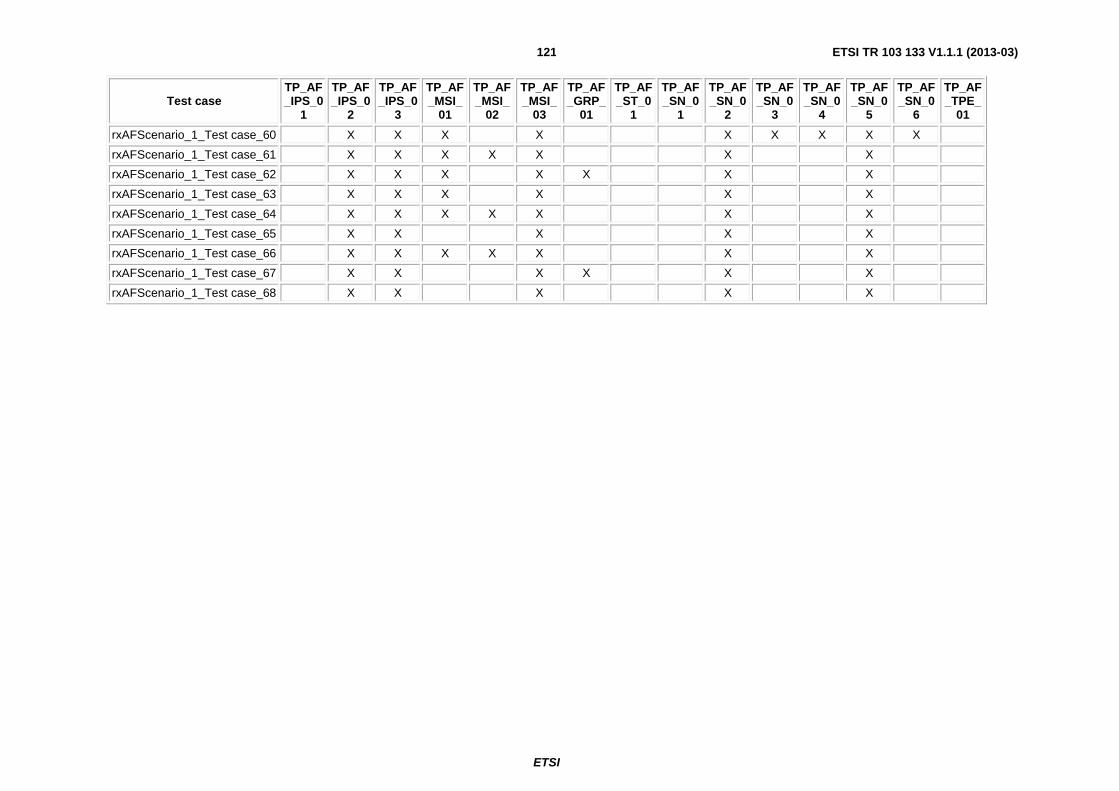
ETSI
ETSI TR 103 133 V1.1.1 (2013-03) 121
Test case TP_AF_IPS_0
1
TP_AF_IPS_0
2
TP_AF_IPS_0
3
TP_AF_MSI_
01
TP_AF_MSI_
02
TP_AF_MSI_
03
TP_AF_GRP_
01
TP_AF_ST_0
1
TP_AF_SN_0
1
TP_AF_SN_0
2
TP_AF_SN_0
3
TP_AF_SN_0
4
TP_AF_SN_0
5
TP_AF_SN_0
6
TP_AF_TPE_
01
rxAFScenario_1_Test case_60 X X X X X X X X X
rxAFScenario_1_Test case_61 X X X X X X X
rxAFScenario_1_Test case_62 X X X X X X X
rxAFScenario_1_Test case_63 X X X X X X
rxAFScenario_1_Test case_64 X X X X X X X
rxAFScenario_1_Test case_65 X X X X X
rxAFScenario_1_Test case_66 X X X X X X X
rxAFScenario_1_Test case_67 X X X X X X
rxAFScenario_1_Test case_68 X X X X X

ETSI
ETSI TR 103 133 V1.1.1 (2013-03) 122
Annex B: Electronic annex: Models and test cases for the tools used for the case studies The electronic annex provides the models which were developed for the different case studies with the different tools. It also provides the test cases which were generated by the tools from the models.
The electronic annex is contained in archive tr_103133v010101p0.zip which accompanies the present document.

ETSI
ETSI TR 103 133 V1.1.1 (2013-03) 123
History
Document history
V1.1.1 March 2013 Publication