
TR-061106 An IEEE 802.15.4 protocol implementation in
106
An IEEE 802.15.4 protocol implementation (in nesC/TinyOS): Reference Guide v1.0 André CUNHA Mário ALVES www.hurray.isep.ipp.pt Technical Report TR-061106 Version: 1.0 Date: Nov 2006
Transcript of TR-061106 An IEEE 802.15.4 protocol implementation in

An IEEE 802.15.4 protocol implementation (in nesC/TinyOS): Reference Guide v1.0
André CUNHA Mário ALVES
www.hurray.isep.ipp.pt
Technical Report
TR-061106
Version: 1.0
Date: Nov 2006

TR-061106 An IEEE 802.15.4 protocol implementation (in nesC/TinyOS): Reference Guide v1.0
© IPP Hurray! Research Group www.hurray.isep.ipp.pt
2
An IEEE 802.15.4 protocol implementation (in nesC/TinyOS): Reference Guide v1.0 André CUNHA, Mário ALVES IPP-HURRAY!
Polytechnic Institute of Porto (ISEP-IPP)
Rua Dr. António Bernardino de Almeida, 431
4200-072 Porto
Portugal
Tel.: +351.22.8340509, Fax: +351.22.8340509
E-mail: {arec,mjf}@isep.ipp.pt
http://www.hurray.isep.ipp.pt
Abstract This technical report is to provide a reference guide to the implementation of the IEEE 802.15.4 protocol in nesC/TinyOS for the MICAz motes. The implementation is provided as a tool that can be used to implement, test and evaluate the current functionalities defined in the protocol standard as well as to enable the development of functionalities not yet implemented and new add-ons to the protocol.

TR-061106 An IEEE 802.15.4 protocol implementation (in nesC/TinyOS): Reference Guide v1.0
© IPP Hurray! Research Group www.hurray.isep.ipp.pt
3
CONTENTS 1. General Notes............................................................. 8
1.1. Context ............................................................................................................. 8 1.2. Functionalities currently supported .................................................................. 8 1.3. Functionalities that are not implemented yet.................................................... 8 1.4. Programming environment............................................................................... 9 1.5. Organization of the implementation / File structure diagram........................... 9
2. Physical Layer Implementation.............................. 12 2.1. Reference Model............................................................................................. 12 2.2. Components Phy and PhyM ........................................................................... 14 2.3. Component Phy .............................................................................................. 14
2.3.1. Provided Interfaces ................................................................................. 14 2.3.2. Component Graph .................................................................................. 15
2.4. Component: PhyM.......................................................................................... 15 2.4.1. Required Interfaces................................................................................. 15 2.4.2. Provided Interfaces ................................................................................. 15 2.4.3. Variables................................................................................................. 16 2.4.4. Functions Implemented ..........................................................................16 2.4.5. Auxiliary Files (Under contrib.hurray.tos.lib.phy):................................ 18
3. MAC Layer Implementation .................................. 21 3.1. Reference Model............................................................................................. 21 3.2. Components Mac and MacM ......................................................................... 23 3.3. Component Mac ............................................................................................. 23
3.3.1. Provided Interfaces ................................................................................. 23 3.3.2. Component Graph .................................................................................. 24
3.4. Component: MacM......................................................................................... 25 3.4.1. Required Interfaces................................................................................. 25 3.4.2. Provided Interfaces ................................................................................. 26 3.4.3. Variables................................................................................................. 26 3.4.4. Functions description.............................................................................. 31
3.5. Implementation of the protocol functionalities.............................................. 35 3.5.1. Buffers .................................................................................................... 35 3.5.2. Data Reception ....................................................................................... 41 3.5.3. TimerAsync and Synchronization .......................................................... 42 3.5.4. MAC Timer Events ................................................................................ 51 3.5.5. Frame Construction ................................................................................ 58 3.5.6. Beacon Management ..............................................................................61 3.5.7. Scanning through channels..................................................................... 68 3.5.8. Association and Disassociation .............................................................. 69 3.5.9. CSMA/CA .............................................................................................. 73 3.5.10. GTS Management................................................................................... 79 3.5.11. Pending data / Indirect Transmissions.................................................... 83
3.6. Auxiliary Files (Under contrib.hurray.tos.lib.mac): ....................................... 85
4. Example Applications ............................................. 96 4.1. AssociationExample application .................................................................... 96 4.2. GTSManagementExample application........................................................... 98

TR-061106 An IEEE 802.15.4 protocol implementation (in nesC/TinyOS): Reference Guide v1.0
© IPP Hurray! Research Group www.hurray.isep.ipp.pt
4
4.3. DataSendExample application......................................................................101 4.4. SimpleRoutingExample application............................................................. 103
5. References .............................................................. 106
Figures Figure 1 - Protocol Stack Architecture. .......................................................................... 11 Figure 2 - TinyOS Implementation Diagram ................................................................. 12 Figure 3 - Physical Layer reference model..................................................................... 12 Figure 4 - Phy - Component Graph ................................................................................ 15 Figure 5 - MAC Layer Reference Model ....................................................................... 21 Figure 6 - MacM component graph................................................................................ 25 Figure 7 - Buffer management example. ........................................................................ 35 Figure 8 - Data transmission sequence chart - originator............................................... 37 Figure 9 - Data transmission sequence chart - recipient................................................. 38 Figure 10 - GTS buffer management - PAN coordinator............................................... 40 Figure 11 - Data reception flow chart............................................................................. 42 Figure 12 - TimerAsyncC component graph.................................................................. 43 Figure 13 - Timer events in superframe structure. ......................................................... 44 Figure 14- Timer.fire flow chat of the TimerAsync component. ................................... 50 Figure 15 - before_bi_fired event flow char................................................................... 52 Figure 16 - bi_fired event flow chart.............................................................................. 53 Figure 17 - sd_fired event flow chart. ............................................................................ 54 Figure 18 - before_time_slot_fired event flow chart...................................................... 55 Figure 19 - time_slot_fired event flow chart. ................................................................. 56 Figure 20 - T_ackwait.fired event flow chart. ................................................................ 58 Figure 21 - General MAC frame format......................................................................... 59 Figure 22 - Format of the frame control field................................................................. 59 Figure 23 - Beacon frame format ................................................................................... 62 Figure 24 - Superframe Specification Format ................................................................ 62 Figure 25 - GTS fields format. ....................................................................................... 62 Figure 26- GTS specification field format. .................................................................... 63 Figure 27 - GTS directions field format. ........................................................................ 63 Figure 28 - GTS descriptor field format......................................................................... 63 Figure 29 - Pending addresses field format. ................................................................... 63 Figure 30 - Pending address specification field format.................................................. 64 Figure 31 - Beacon creation flow chart. ......................................................................... 65 Figure 32 - Beacon generation sequence chart. .............................................................. 66 Figure 33 - Beacon transmission example...................................................................... 66 Figure 34 - Association request frame format. ............................................................... 69 Figure 35 - Capability information field format............................................................. 69 Figure 36 - Device association message sequence chart. ............................................... 70 Figure 37 - Coordinator association message sequence chart. ....................................... 71 Figure 38 - Association mechanism example................................................................. 72 Figure 39 - Disassociation mechanism example. ........................................................... 72 Figure 40 - CSMA/CS algorithm. .................................................................................. 74
TR-061106 An IEEE 802.15.4 protocol implementation (in nesC/TinyOS): Reference Guide v1.0
© IPP Hurray! Research Group www.hurray.isep.ipp.pt
5
Figure 41 - perform_csma_ca() function flow chart. ..................................................... 76 Figure 42 - backoff_fired event flow chart..................................................................... 77 Figure 43 – start_csma_ca_slotted() function flow chart. ..............................................77 Figure 44 - perform_csma_ca_slotted() function flow chart.......................................... 78 Figure 45 - GTS allocation request flow chart. .............................................................. 80 Figure 46 – GTS allocation mechanism example........................................................... 80 Figure 47 - CFP defragmentation on GTS deallocations. .............................................. 81 Figure 48 - GTS deallocation request flow chart. .......................................................... 82 Figure 49 – GTS deallocation mechanism example....................................................... 83 Figure 50 - Pending address list construction diagram................................................... 84 Figure 51 – Data request example. ................................................................................. 85 Figure 52 - AssociationExample component graph. ...................................................... 97 Figure 53 - AssociationExample sniffer output.............................................................. 98 Figure 54 - GTSManagementExample component graph.............................................. 99 Figure 55 - GTSManagementExample sniffer output. ................................................. 101 Figure 56 - DataSendExample component graph......................................................... 102 Figure 57 - DataSendExample sniffer output ............................................................... 103 Figure 58 -SimpleRoutingExample component graph. ................................................ 104 Figure 59 - SimpleRoutingExample sniffer output. ..................................................... 105
Tables Table 1 - Summary of the primitives supported by each PD-SAP interface.................. 13 Table 2 - Summary of the primitives supported by each PLME-SAP interface. ........... 14 Table 3 - Physical layer constants. ................................................................................. 19 Table 4 - Physical PAN Information Base attributes..................................................... 19 Table 5 - PHY general enumeration descriptions........................................................... 20 Table 6 - PHY GET/SET reference PIB enumerations. ................................................. 20 Table 7 - Summary of the primitives supported by each MCPS-SAP interface. ........... 22 Table 8 - Summary of the primitives supported by each MLME-SAP interface. .......... 23 Table 9 - MICAz clock ticks granularity comparison....................................................45 Table 10 - MICAz time slot durations - Effective values...............................................45 Table 11 - MICAz time slot durations - Theoretical values. .......................................... 46 Table 12 - MICAz beacon interval durations - Effective values.................................... 46 Table 13 - MICAz beacon interval durations - Theoretical values. ............................... 46 Table 14 - Address fields - possible sizes and combinations. ........................................ 60 Table 15 - Address fields - size reference. ..................................................................... 60 Table 16 - PAN Descriptor attributes description. ......................................................... 68 Table 17 - Protocol MAC layer constants description. ..................................................86 Table 18 - MAC layer auxiliary constants description................................................... 87 Table 19 - Structure definitions on the mac_const.h file................................................ 88 Table 20 - General MAC enumeration description. .......................................................89 Table 21 - Disassociation status enumeration decription. ..............................................89 Table 22 - Command type enumerations description..................................................... 90 Table 23 - Association response status enumerations description. ................................ 90 Table 24 - MAC GET/SET reference PIB enumerations description. ........................... 91 Table 25 - GTS direction enumeration descriptions....................................................... 91 Table 26 - frame_format.h structures descriptions......................................................... 92 Table 27 - frame_format.h constants descriptions.......................................................... 93

TR-061106 An IEEE 802.15.4 protocol implementation (in nesC/TinyOS): Reference Guide v1.0
© IPP Hurray! Research Group www.hurray.isep.ipp.pt
6
Code Examples Code Example 1 - Indirect transmissiton structure definition........................................ 39 Code Example 2 - gts_slot_element structure definition................................................40 Code Example 3 - Mac frame control construction function. ........................................ 59 Code Example 4 - MPDU structure definition in the frame_format.h. .......................... 60 Code Example 5 - frame_format.h structure definition example. .................................. 61 Code Example 6 - Data frame construction example. .................................................... 61 Code Example 7 - MLME_BEACON_NOTIFY indication event . .............................. 67 Code Example 8- GTSinfoEntryType structure definition............................................. 79 Code Example 9- GTSinfoEntryType_null structure definition. ................................... 82

TR-061106 An IEEE 802.15.4 protocol implementation (in nesC/TinyOS): Reference Guide v1.0
© IPP Hurray! Research Group www.hurray.isep.ipp.pt
7
Acronyms and abbreviations ACL access control list AES advanced encryption standard BE backoff exponent BER bit error rate BI beacon interval BO beacon order BPSK binary phase-shift keying BSN beacon sequence number CAP contention access period CBC-MAC cipher block chaining message authentication code CCA clear channel assessment CFP contention-free period CID cluster identifier CLH cluster head CRC cyclic redundancy check CSMA-CA carrier sense multiple access with collision avoidance CTR counter mode CW contention window (length) DSN data sequence number DSSS direct sequence spread spectrum ED energy detection FCS frame check sequence FFD full-function device FH frequency hopping FHSS frequency hopping spread spectrum GTS guaranteed time slot IFS interframe space or spacing LAN local area network LIFS long interframe spacing LLC logical link control LQ link quality LQI link quality indication LPDU LLC protocol data unit LR-WPAN low-rate wireless personal area network LSB least significant bit MAC medium access control MCPS MAC common part sublayer MCPS-SAP MAC common part sublayer-service access point MFR MAC footer
MHR MAC header MLME MAC sublayer management entity MLME-SAP MAC sublayer management entity-service access point MSB most significant bit MSC message sequence chart MPDU MAC protocol data unit MSDU MAC service data unit NB number of backoff (periods) OSI open systems interconnection PAN personal area network PD-SAP PHY data service access point PDU protocol data unit PER packet error rate PHR PHY header PHY physical layer PIB PAN information base PLME physical layer management entity PLME-SAP physical layer management entity-service access point PPDU PHY protocol data unit PSDU PHY service data unit RF radio frequency RFD reduced-function device RSSI received signal strength indication RX receive or receiver SAP service access point SD superframe duration SPDU SSCS protocol data units SDU service data unit SFD start-of-frame delimiter SHR synchronization header SIFS short interframe spacing SO superframe order SRD short-range device SSCS service specific convergence sublayer TRX transceiver TX transmit or transmitter WLAN wireless local area network WPAN wireless personal area network

TR-061106 An IEEE 802.15.4 protocol implementation (in nesC/TinyOS): Reference Guide v1.0
© IPP Hurray! Research Group www.hurray.isep.ipp.pt
8
1. General Notes
1.1. Context The purpose of this technical report is to provide a reference guide to the implementation of the IEEE 802.15.4 protocol [1] in nesC/TinyOS[2,3] for the MICAz[4] motes. During this description some parts of the protocol standard are explained and referenced, nevertheless it is important to have a previous knowledge on the functionalities of the IEEE 802.15.4 protocol. This implementation is provided as a tool that can be used to implement, test and evaluate the current functionalities defined in the protocol standard as well as to enable the development of functionalities not yet implemented and new add-ons to the protocol.
This technical report is structured based on the different IEEE 802.15.4 mechanisms implemented. The component graphs shown in this document are automatically generated by the nesdoc application (associated with the nesC programming environement in TinyOS). In Reference [5] there is a technical overview of the IEEE 802.15.4 protocol.
1.2. Functionalities currently supported
The current version of the implementation (v1.0) supports the following IEEE 802.15.4 functionalities:
• CSMA/CA algorithm – slotted version; • GTS Mechanism; • Indirect transmission mechanism; • Direct / Indirect / GTS Data Transmission; • Beacon Management; • Frame construction – Short Addressing Fields only and extended addressing
fields in the association request; • Association/Disassociation Mechanism; • MAC PIB Management; • Frame Reception Conditions;
1.3. Functionalities that are not implemented yet The following functionalities are not implemented or tested in the current version of the implementation (v1.0):

TR-061106 An IEEE 802.15.4 protocol implementation (in nesC/TinyOS): Reference Guide v1.0
© IPP Hurray! Research Group www.hurray.isep.ipp.pt
9
• Unslotted version CSMA/CA – Implemented but not fully tested; • Extended Address Fields of the Frames; • IntraPAN Address Fields of the Frames; • Channel Scan; • Orphan Devices; • Frame Reception Conditions (Verify Conditions); • Security – Out of the scope of this implementation;
Besides these missing functionalities, many improvements can be made to optimize
this implementation especially in terms of memory usage. For example, one option to save memory could be removing the components wiring modules and replace them with only one that wires them all. Another option is to optimize the buffers because they are the most memory consuming entities.
1.4. Programming environment This implementation was developed for TinyOS version 1.1.15 under the Cygwin for Windows XP environment. The application used to write code was the Programmers Notepad 2 that provides code highlighting. The hardware used was the Crossbow MICAz motes. These “IEEE 802.15.4-compliant” motes operate in the 2.4 GHz ISM band and have a 16 Mhz Atmel ATMega128L microcontroller [6] (with 128 kB of program Flash) and a Chipcon CC2420 802.15.4 radio transceiver [7] (allowing a 250 kbps data rate). The MIB510 programming board was used to program the motes. This programmer can upload the applications to motes through the COM port and allow a debug mechanism by sending data through the COM port and reading it in a COM port software listener, like the ListenRaw (found in the TinyOS distribution) or the Windows HiperTerminal. This debug mechanism raises a problem concerning the hardware operation because the relaying of data through the COM port blocks all the other mote operations, while this data is being send. This can cause synchronization problems. We also use the MIB600 programmer to program the motes through the IP network. In order to overcome the COM debug problems we use an IEEE 802.15.4 packet sniffer provided by Chipcon the CC2420 Packet Sniffer for IEEE 802.15.4 v1.0. This application works in conjunction with a CC2400EB board with a CC2420 radio transceiver. This sniffer shows the packets transmitted and provide a good debug mechanism by transmitting debug data in the packets payloads. A JTAG adapter can also be used for debug purposes but that was not used during the development of this implementation.
1.5. Organization of the implementation / File structure diagram
The implementation uses files already provided in TinyOS and its located in the contrib/hurray folder. The directory structure is similar to the TinyOS root folder. The next list shows all the files created for this implementation and their respective location.

TR-061106 An IEEE 802.15.4 protocol implementation (in nesC/TinyOS): Reference Guide v1.0
© IPP Hurray! Research Group www.hurray.isep.ipp.pt
10
contrib/hurray/tos/interfaces – Generic Interfaces
• TimerAsync.nc – Interface for the TimerAsyncM component contrib/hurray/tos/interfaces/ieee802154.mac – Connection interfaces between the MAC and the upper layer.
• MCPS_DATA.nc – MAC Common Part Sublayer Data-Service Access Point; • MCPS_PURGE.nc - MAC Common Part Sublayer Purge Service Access Point; • MLME_ASSOCIATE.nc – MAC Layer Management Entity Associate Service
Access Point; • MLME_BEACON_NOTIFY.nc - MAC Layer Management Entity Beacon
Notify Service Access Point; • MLME_COMM_STATUS.nc - MAC Layer Management Entity
Communication Status Service Access Point; • MLME_DISASSOCIATE.nc – MAC Layer Management Entity Disassociate
Service Access Point; • MLME_GET.nc - MAC Layer Management Entity Get Service Access Point; • MLME_GTS.nc - MAC Layer Management Entity Guaranteed Time Slot
Service Access Point; • MLME_POLL.nc - MAC Layer Management Entity Poll Service Access Point; • MLME_RESET.nc - MAC Layer Management Entity Reset Service Access
Point; • MLME_SCAN.nc - MAC Layer Management Entity Scan Service Access Point; • MLME_SET.nc - MAC Layer Management Entity Set Service Access Point; • MLME_START.nc - MAC Layer Management Entity Start Service Access
Point; • MLME_SYNC.nc - MAC Layer Management Entity Synchronize Service
Access Point; • MLME_SYNC_LOSS.nc - MAC Layer Management Entity Synchronization
Loss Service Access Point. contrib/hurray/tos/interfaces/ieee802154.phy - Connection interfaces between the MAC and PHY layers.
• PD_DATA.nc – Phy Data-Service Access Point; • PLME_CCA.nc - Physical Layer Management Entity - Clear Channel
Assessment -Service Access Point; • PLME_ED.nc - Physical Layer Management Entity – Energy Detection -
Service Access Point; • PLME_GET.nc - Physical Layer Management Entity Get-Service Access Point; • PLME_SET.nc - Physical Layer Management Entity Set -Service Access Point; • PLME_SET_TRX_STATE.nc - Physical Layer Management Entity Set
Transceiver State-Service Access. contrib/hurray/tos/lib/mac – MAC layer implementation files
• Mac.nc – Configuration of the MacM implementation module; • MacM.nc – MAC layer implementation;
TR-061106 An IEEE 802.15.4 protocol implementation (in nesC/TinyOS): Reference Guide v1.0
© IPP Hurray! Research Group www.hurray.isep.ipp.pt
11
• mac_const.h – MAC layer constants; • mac_enumerations.h – MAC layer enumerations.
contrib/hurray/tos/lib/phy – Physical layer implementation files
• Phy.nc – Configuration of the PhyM implementation module; • PhyM.nc – Physical layer implementation; • phy_const.h – Physical layer constants; • phy_enumerations.h – Physical layer enumerations.
contrib/hurray/tos/system – Generic system modules
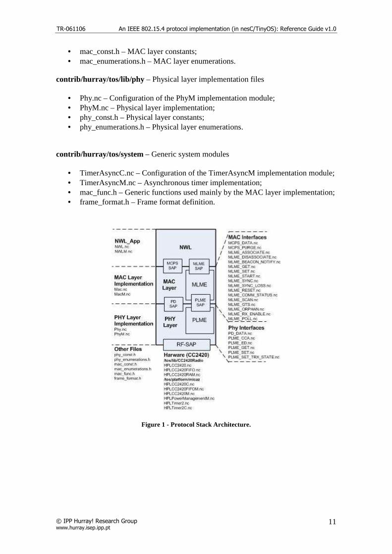
• TimerAsyncC.nc – Configuration of the TimerAsyncM implementation module; • TimerAsyncM.nc – Asynchronous timer implementation; • mac_func.h – Generic functions used mainly by the MAC layer implementation; • frame_format.h – Frame format definition.
Figure 1 - Protocol Stack Architecture.

TR-061106 An IEEE 802.15.4 protocol implementation (in nesC/TinyOS): Reference Guide v1.0
© IPP Hurray! Research Group www.hurray.isep.ipp.pt
12
Figure 2 - TinyOS Implementation Diagram
2. Physical Layer Implementation
The IEEE 802.15.4 physical layer is responsible for the implementation of the following functionalities:
• Activation and deactivation of the radio transceiver; • Energy Detection(ED) within the current channel; • Link quality indicator (LQI) for received packets; • Clear Channel Assessment (CCA) for Carrier Sense Multiple Access – Collision
Avoidance (CSMA-CA); • Channel frequency selection; • Data transmission and reception;
2.1. Reference Model
Figure 3 - Physical Layer reference model.

TR-061106 An IEEE 802.15.4 protocol implementation (in nesC/TinyOS): Reference Guide v1.0
© IPP Hurray! Research Group www.hurray.isep.ipp.pt
13
The RF-SAP comprehends the interface with the physical radio via the RF firmware of the CC2420 and hardware, already provided in the TinyOS implementation. The files included are the following: Interfaces under the contrib.hurray.tos.lib.CC2420Radio directory:
• HPLCC2420 • HPLCC2420FIFO • HPLCC2420RAM
Components under contrib.hurray.tos.platform.MICAz directory:
• HPLCC2420C • HPLCC2420FIFOM • HPLCC2420M • HPLPowerManagementM • HPLTimer2 • HPLTimer2C
The PD-SAP comprehends the interface to exchange data packets between MAC
and PHY. The interface file is under contrib.hurray.tos.interfaces.ieee802154.phy directory:
• PD_DATA – data transfer between the Phy layer and the MAC layer. The next table summarizes the primitives supported by PD-SAP interface [1 pag 32]
Interface Name Request Indication Response Confirm
PD_DATA X X X
Table 1 - Summary of the primitives supported by each PD-SAP interface.
The Physical Layer Management Entity –SAP (PLME-SAP) comprehends the
interfaces between the MAC and the PHY used for exchanging management information. The interface files are under contrib.hurray.tos.interfaces.ieee802154.phy directory:
• PLME_CCA – clear channel assessment • PLME_ED - energy detection • PLME_GET - retrieve PHY PIB parameters • PLME_SET– set PHY PIB parameters • PLME_TRX-ENABLE – enable/disable transceiver
The next table summarizes the primitives supported by each PLME-SAP interface [1 pag 34]
TR-061106 An IEEE 802.15.4 protocol implementation (in nesC/TinyOS): Reference Guide v1.0
© IPP Hurray! Research Group www.hurray.isep.ipp.pt
14
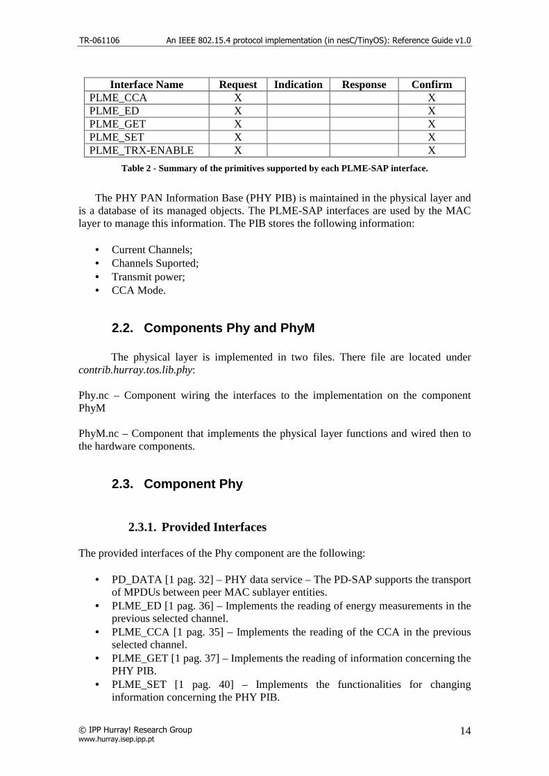
Interface Name Request Indication Response Confirm
PLME_CCA X X PLME_ED X X PLME_GET X X PLME_SET X X PLME_TRX-ENABLE X X
Table 2 - Summary of the primitives supported by each PLME-SAP interface.
The PHY PAN Information Base (PHY PIB) is maintained in the physical layer and
is a database of its managed objects. The PLME-SAP interfaces are used by the MAC layer to manage this information. The PIB stores the following information:
• Current Channels; • Channels Suported; • Transmit power; • CCA Mode.
2.2. Components Phy and PhyM
The physical layer is implemented in two files. There file are located under contrib.hurray.tos.lib.phy: Phy.nc – Component wiring the interfaces to the implementation on the component PhyM PhyM.nc – Component that implements the physical layer functions and wired then to the hardware components.
2.3. Component Phy
2.3.1. Provided Interfaces
The provided interfaces of the Phy component are the following:
• PD_DATA [1 pag. 32] – PHY data service – The PD-SAP supports the transport of MPDUs between peer MAC sublayer entities.
• PLME_ED [1 pag. 36] – Implements the reading of energy measurements in the previous selected channel.
• PLME_CCA [1 pag. 35] – Implements the reading of the CCA in the previous selected channel.
• PLME_GET [1 pag. 37] – Implements the reading of information concerning the PHY PIB.
• PLME_SET [1 pag. 40] – Implements the functionalities for changing information concerning the PHY PIB.
TR-061106 An IEEE 802.15.4 protocol implementation (in nesC/TinyOS): Reference Guide v1.0
© IPP Hurray! Research Group www.hurray.isep.ipp.pt
15
• PLME_SET_TRX_STATE [1 pag. 39] – Implements the functionalities for changing the internal operating state of the transceiver.
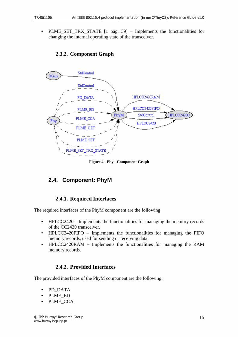
2.3.2. Component Graph
Figure 4 - Phy - Component Graph
2.4. Component: PhyM
2.4.1. Required Interfaces
The required interfaces of the PhyM component are the following:
• HPLCC2420 – Implements the functionalities for managing the memory records of the CC2420 transceiver.
• HPLCC2420FIFO – Implements the functionalities for managing the FIFO memory records, used for sending or receiving data.
• HPLCC2420RAM – Implements the functionalities for managing the RAM memory records.
2.4.2. Provided Interfaces
The provided interfaces of the PhyM component are the following:
• PD_DATA • PLME_ED • PLME_CCA
TR-061106 An IEEE 802.15.4 protocol implementation (in nesC/TinyOS): Reference Guide v1.0
© IPP Hurray! Research Group www.hurray.isep.ipp.pt
16
• PLME_GET • PLME_SET • PLME_SET_TRX_STATE
2.4.3. Variables
The component global variables are described in the following list:
• norace uint16_t gCurrentParameters[14] - Used to store the transceiver global parameters.
• phyPIB phy_PIB – Used to store the physical layer PAN Information Base. The phyPIB structure is defined in the phyConst.h file
• uint8_t currentRxTxState = PHY_TRX_OFF – Gives information about the
current transceiver state. • norace MPDU rxmpdu – Temporary variable that stores receiving data. • MPDU *rxmpdu_ptr - Pointer for the rxmpdu variable
2.4.4. Functions Implemented
Common Functions: command result_t StdControl.init (void)
This function is called on the initialization of the component. In this function the hardware components are initialized and the transceiver global parameters are assigned (variable gCurrentParameters). The Phy PIB is assigned with the init values. The constants defined to access the memory positions of the transceiver, provided in TinyOS, are located in the CC2420const.h file under contrib.hurray.tos.lib.CC2420Radio directory. command result_t StdControl.start (void)
This function is called on the start of the component. The transceiver module are started with the initial values and all is parameters are set. command result_t StdControl.stop (void)
This function is called on the stop of the component. Stops all the transceiver activity and disables all FIFO interrupts. Interface implementations (command implementations):
• PD_DATA [1 pag. 32] async command result_t PD_DATA.request (uint8_t psduLength, uint8_t *psdu)

TR-061106 An IEEE 802.15.4 protocol implementation (in nesC/TinyOS): Reference Guide v1.0
© IPP Hurray! Research Group www.hurray.isep.ipp.pt
17
This command is used when the MAC layer need to send data. The data, pointed by the second argument, is transferred to the output buffer of the transceiver and a transmit command is issued to the hardware components. This command is issue asynchronously because of the time constrains for issuing a frame. The Phy layer must send the data almost immediately after the request to send.
• PLME_ED [1 pag. 36] command result_t PLME_ED.request (void) This command is used when the MAC layer need to read the RSSI registry of the transceiver. The Phy layer just issues a command to the hardware modules to read the RSSI memory position.
• PLME_CCA [1 pag. 35] command result_t PLME_CCA.request (void) This command is used when the MAC layer need to check is the channel is clear. The function TOSH_READ_CC_CCA_PIN() is called in order to do that. If the return of the function is 1 then the channel is busy otherwise the channel is idle. This macro functions, provided in TinyOS, are defined in the avrhardware.h under the contrib..hurray.tos.platform.avrmote directory.
• PLME_GET [1 pag. 37] command result_t PLME_GET.request (uint8_t PIBAttribute) This command is used when the MAC layer need to read the values of the PHY PIB.
• PLME_SET [1 pag. 40] command result_t PLME_SET.request (uint8_t PIBAttribute, uint8_t PIBAttributeValue) This command is used when the MAC layer need to change the values of the PHY PIB.
• PLME_SET_TRX_STATE [1 pag. 39] command result_t PLME_SET_TRX_STATE.request (uint8_t state) This command is used when the MAC layer need to change the current state of the transceiver. Hardware Event Functions: async event result_t HPLCC2420.FIFOPIntr (void) Asynchronous hardware interrupt indicating the reception of data. When this event is triggered the data in the input FIFO is pointed by the rxmpdu_ptr variable pointer. async event result_t HPLCC2420RAM.readDone (uint16_t addr, uint8_t length, uint8_t *buffer) Asynchronous hardware interrupt indicating the completion of a read command. Meanwhile we have no use for this hardware event. async event result_t HPLCC2420RAM.writeDone (uint16_t addr, uint8_t length, uint8_t *buffer)

TR-061106 An IEEE 802.15.4 protocol implementation (in nesC/TinyOS): Reference Guide v1.0
© IPP Hurray! Research Group www.hurray.isep.ipp.pt
18
Asynchronous hardware interrupt indicating the completion of a write command. Meanwhile we have no use for this hardware event. async event result_t HPLCC2420FIFO.RXFIFODone (uint8_t length, uint8_t *data) Asynchronous hardware interrupt indicating the completion of a read command in the input buffer of the transceiver (received data). Meanwhile we have no use for this hardware event. async event result_t HPLCC2420FIFO.TXFIFODone (uint8_t length, uint8_t *data) Asynchronous hardware interrupt indicating the completion of a write command in the output buffer of the transceiver (data for transmission). Meanwhile we have no use for this hardware event. Other Functions: bool SetRegs(void) Function used to configure the CC2420 registers with current values - Readback 1st register written to make sure electrical connection OK
uint8_t GetRFPower(void) Function used to get the RF power value from the gCurrentParameters variable. result_t SetRFPower(uint8_t power) Function used to set the RF power value of the CC2420 transceiver. The power argument indicates the power level. Admissible values varies between 31, full power (0dbm gain) and 3, minimum power (-25dbm gain). result_t VREFOn (void) Turns on the 1.8V references on the CC2420. result_t VREFOff (void) Turns off the 1.8V references on the CC2420.
result_t TunePreset (uint8_t chnl) Function used to select the current radio channel. Valid channel values are 11 through 26. result_t TuneManual (uint16_t DesiredFreq) Function used to tune the radio to a given frequency.
result_t setShortAddress(uint16_t addr) Function used to assign the short address of the mote. In the init function the short address of the mote is assigned with the TOS_LOCAL_ADDRESS. This constant is assigned during compilation time.
2.4.5. Auxiliary Files (Under contrib.hurray.tos.lib.phy):
phy_const.h This file contains the protocol constants definition related with the Phy layer. These constants are defined in next table. [1 pag. 44]
Constant Description Value aMaxPHYPacketSize The maximum PSDU size (in octets) 127

TR-061106 An IEEE 802.15.4 protocol implementation (in nesC/TinyOS): Reference Guide v1.0
© IPP Hurray! Research Group www.hurray.isep.ipp.pt
19
the PHY shall be able to receive aTurnaroundTime RX-to-TX or TX-to-RX maximum
turnaround time 12 symbol periods
Table 3 - Physical layer constants.
There is also the definition of the initial values for the PHY PIB along with the structure of the PHY PIB. The PIB attributes are defined in the next table. [1 pag 45] Note that the transmit power is hardware constrained and it has to be within the values accepted, in this case, by the SetRFPower function.
Attribute Type Range Description
phyCurrentChannel Integer 0–26 The RF channel to use for all following transmissions and receptions.
phyChannelsSupported Bitmap The 5 most significant bits (MSBs) (b27,... , b31) of phyChannelsSupported shall be reserved and set to 0, and the 27 LSBs (b0,b1, ... b26) shall indicate the status (1=available, 0=unavailable) for each ofthe 27 valid channels (bk shall indicate the status of channel k as in 6.1.2).
phyTransmitPower Bitmap 0x00-0xbf The 2 MSBs represent the tolerance on the transmit power: 00 = ± 1 dB 01 = ± 3 dB 10 = ± 6 dB The 6 LSBs represent a signed integer in twos-complement format, corresponding to the nominal transmit power of the device in decibels relative to 1 mW. The lowest value of phyTransmitPower shall be interpreted as less than or equal to –32 dBm.
phyCCAMode Integer 1–3 The CCA mode.
Table 4 - Physical PAN Information Base attributes.
phy_enumerations.h This file contains the enumeration values used in the PHY layer. There are two enumeration tables: one represents the general PHY enumeration description [1 pag.42] and the other represents the values used in the PLME_SET and PLME_GET functions for referring to the PHY PIB attributes.
The following tables describe the enumerations.
Enumeration Value Description PHY_BUSY 0x00 The CCA attempt has detected a busy channel.

TR-061106 An IEEE 802.15.4 protocol implementation (in nesC/TinyOS): Reference Guide v1.0
© IPP Hurray! Research Group www.hurray.isep.ipp.pt
20
PHY_BUSY_RX 0x01 The transceiver is asked to change its state while receiving.
PHY_BUSY_TX 0x02 The transceiver is asked to change its state while transmitting.
PHY_FORCE_TRX_OFF 0x03 The transceiver is to be switched off. PHY_IDLE 0x04 The CCA attempt has detected an idle channel. PHY_INVALID_PARAMETER 0x05 A SET/GET request was issued with a parameter
in the primitive that is out of the valid range. PHY_RX_ON 0x06 The transceiver is in or is to be configured into
the receiver enabled state. PHY_SUCCESS 0x07 A SET/GET, an ED operation, or a transceiver
state change was successful PHY_TRX_OFF 0x08 The transceiver is in or is to be configured into
the transceiver disabled state. PHY_TX_ON 0x09 The transceiver is in or is to be configured into
the transmitter enabled state PHY_UNSUPPORTED_ATTRIBUTE
0x0a A SET/GET request was issued with the identifier of an attribute that is not supported.
Table 5 - PHY general enumeration descriptions.
Enumeration Value Description PHYCURRENTCHANNEL 0x00 The GET/SET reference of the PIB
phyCurrentChannel. PHYCHANNELSSUPPORTED 0x01 The GET/SET reference of the PIB
phyChannelsSupported. PHYTRANSMITPOWER 0x02 The GET/SET reference of the PIB
phyTransmitPower. PHYCCAMODE 0x03 The GET/SET reference of the PIB
phyCCAMode.
Table 6 - PHY GET/SET reference PIB enumerations.

TR-061106 An IEEE 802.15.4 protocol implementation (in nesC/TinyOS): Reference Guide v1.0
© IPP Hurray! Research Group www.hurray.isep.ipp.pt
21
3. MAC Layer Implementation
The IEEE 802.15.4 MAC layer is responsible for the implementation of the following functionalities:
• Generating network beacons if the device is a coordinator; • Synchronizing to the beacons; • Supporting PAN association and disassociation; • Supporting device security; • Employing the CSMA-CA mechanism for channel access; • Handling and maintaining the GTS mechanism; • Providing a reliable link between two peer MAC entities.
3.1. Reference Model
Figure 5 - MAC Layer Reference Model
The MAC layer provides to the upper layer two SAP. The MAC Common Part Sublayer (MCPS-SAP) and the MAC Layer Management Entity (MLME-SAP). The PD-SAP and the PLME-SAP are used to connect the MAC Layer with the functionalities provided by the PHY Layer.
The MCPS-SAP comprehends the MSDU data transfer between the MAC layer and the upper layer. The files included in the interfaces for the MCPS-SAP are the following and are located under contrib.hurray.tos.interfaces.ieee802154.mac directory:
• MCPS_DATA - exchange data packets between MAC and PHY; • MCPS_PURGE - purge an MSDU from the transaction queue.

TR-061106 An IEEE 802.15.4 protocol implementation (in nesC/TinyOS): Reference Guide v1.0
© IPP Hurray! Research Group www.hurray.isep.ipp.pt
22
The next table summarizes the primitives supported by each MCPS-SAP interface [1 pag 56]
Interface Name Request Indication Response Confirm MCPS_DATA X X X MCPS_PURGE X X
Table 7 - Summary of the primitives supported by each MCPS-SAP interface.
The MLME-SAP comprehends the exchange of management commands between
the MAC layer and the upper layer. The files included in the interfaces for the MLME-SAP are the following and are located under contrib.hurray.tos.interfaces.ieee802154.mac directory:
• MLME_ASSOCIATE - network association • MLME_DISASSOCIATE – network association • MLME_BEACON-NOTIFY – beacon notification • MLME_GET - retrieve MAC PIB parameters • MLME_GTS - GTS management • MLME_ORPHAN - orphan device management (NOT IMPLEMENTED) • MLME_RESET – request for MLME to perform reset • MLME_RX-ENABLE - enabling/disabling of radio system • MLME_SCAN - scan radio channels (NOT IMPLEMENTED) • MLME_COMM_STATUS – communication status • MLME_SET– retrieves MAC PIB parameters • MLME_START – beacon generation management • MLME_SYNC – synchronization request • MLME_SYNC-LOSS - device synchronization • MLME-POLL - beaconless synchronization The next table summarizes the primitives supported by each MLME-SAP interface [1 pag. 64].
Interface Name Request Indication Response Confirm MLME_ASSOCIATE X X X X MLME_DISASSOCIATE X X X MLME_BEACON-NOTIFY X MLME_GET X X MLME_GTS X X X MLME_ORPHAN X X MLME_RESET X X MLME_RX- X X MLME_SCAN X X MLME_COMM_STATUS X MLME_SET X X MLME_START X X MLME_SYNC X MLME_SYNC-LOSS X

TR-061106 An IEEE 802.15.4 protocol implementation (in nesC/TinyOS): Reference Guide v1.0
© IPP Hurray! Research Group www.hurray.isep.ipp.pt
23
MLME-POLL X X
Table 8 - Summary of the primitives supported by each MLME-SAP interface.
The MAC PAN Information Base (MAC PIB) is maintained in the MAC layer
and is a database of its managed objects. The MLME-SAP interfaces are used by the MAC upper layer to manage this information. The PIB stores the following information:
• Acknowledgment Wait Duration; • Association Permit; • Automatic Data Request; • Battery Life Extension Option; • Battery Life Extension Periods; • Beacon Payload; • Beacon Payload Length; • Beacon Order; • Beacon Transmit Time; • Beacon Sequence Number; • Coordinator Extended Address; • Coordinator Short Address; • Data Sequence Number; • GTS Permit Option; • Maximum CSMA Backoffs Attempts; • Minimul Backoff Exponent; • PAN identifier; • Promiscuous Mode Option; • Receive mode when the transceiver is idle option; • Short Address; • Superframe Order; • Transaction Persistence Time;.
3.2. Components Mac and MacM The MAC layer is implemented in two files. There file are located under contrib.hurray.tos.lib.mac: Mac.nc – Component wiring the interfaces to the implementation on the component MacM MacM.nc – Component that implements the MAC layer functions that will be provided to the upper layer.
3.3. Component Mac
3.3.1. Provided Interfaces

TR-061106 An IEEE 802.15.4 protocol implementation (in nesC/TinyOS): Reference Guide v1.0
© IPP Hurray! Research Group www.hurray.isep.ipp.pt
24
The provided interfaces of the Mac component are the following:
• MLME_START [1 pag. 100] – Used for the coordinator to start sending beacons or use a new superframe configuration.
• MLME_ASSOCIATE [1 pag. 64] – Used to create an association request directed to the coordinator.
• MLME_DISASSOCIATE [1 pag. 71] – Used to create a disassociation requent directed to the coordinator.
• MLME_SYNC [1 pag. 104] – Used to enable the MAC layer to start synchronizing the coordinator by always keep track of the beacon.
• MLME_SYNC_LOSS [1 pag. 105] – Used by the MAC layer to inform the upper layer about the loss of synchronization with a coordinator.
• MLME_SCAN [1 pag. 92] - Implements the channel scan mechanist in order to inform the upper layer about the energy detection on each channel.
• MLME_RESET [1 pag. 88] – Used to request a reset operation in the MAC layer.
• MLME_BEACON_NOTIFY [1 pag. 75] – Used by the MAC layer to inform the upper layer about the PAN descriptor and pending addresses contained in the beacon received.
• MLME_COMM_STATUS [1 pag. 96] – Used by the MAC layer to inform the upper layer about the communication status.
• MLME_SET [1 pag. 98] - Used to write in the attributes of the MAC PAN Information Base.
• MLME_GET [1 pag. 78] – Used to read the attributes of the MAC PAN Information Base.
• MLME_GTS [1 pag.79] – Used to create a GTS allocation request directed to the coordinator. This interface also informs the MAC upper layer about the status of the allocation.
• MCPS_DATA [1 pag. 56] – Implement the data exchange between the MAC layer and the next upper layer.
• MCPS_PURGE [1 pag. 61] – Used to purge a data frame from the transaction queue.
3.3.2. Component Graph

TR-061106 An IEEE 802.15.4 protocol implementation (in nesC/TinyOS): Reference Guide v1.0
© IPP Hurray! Research Group www.hurray.isep.ipp.pt
25
Figure 6 - MacM component graph.
3.4. Component: MacM
3.4.1. Required Interfaces
The required interfaces of the MacM component are the following:
• PD_DATA - PHY data service. Implemented in the PhyM.nc. • PLME_CCA – Clear Channel Assessment. Implemented in the PhyM.nc. • PLME_SET – Set PHY PIB attributes. Implemented in the PhyM.nc.

TR-061106 An IEEE 802.15.4 protocol implementation (in nesC/TinyOS): Reference Guide v1.0
© IPP Hurray! Research Group www.hurray.isep.ipp.pt
26
• PLME_SET_TRX_STATE – Set the transceiver state. Implemented in the PhyM.nc.
• PLME_GET – Get PHY PIB attributes values. Implemented in the PhyM.nc. • PLME_ED – Perform Energy Detection. Implemented in the PhyM.nc. • Random - Interface to a simple pseudorandom number generator. Currently this
interface is implemented by the RandomLFSR, which uses a linear feedback shift register to generate the sequence and mote address to initialize the register. Already developed in TinyOS.
• Leds – Mote Leds interface. • Timer - T_scan_duration timer. TinyOS generic timer component (TimerC). • Timer - T_ResponseWaitTime timer. TinyOS generic timer component
(TimerC). • Timer - T_ackwait timer. TinyOS generic timer component (TimerC). • TimerAsync – Asynchronous timer component. Refer to section TimerAsync
and Synchronization.
3.4.2. Provided Interfaces
The provided interfaces of the MacM component are the following:
• MLME_START • MLME_ASSOCIATE • MLME_DISASSOCIATE • MLME_SYNC • MLME_SYNC_LOSS • MLME_SCAN • MLME_RESET • MLME_BEACON_NOTIFY • MLME_COMM_STATUS • MLME_SET • MLME_GET • MLME_GTS • MCPS_DATA • MCPS_PURGE
3.4.3. Variables
The component global variables are described in the following list. General variables: • uint32_t aExtendedAddress0 – Extended address of the device (first 4 bytes); • uint32_t aExtendedAddress1 - Extended address of the device (last 4 bytes); • macPIB mac_PIB – Mac PAN Information Base, this variable is a structure of the
MAC PIB [1 pag. 135]; • bool PANCoordinator – 1 if the device is a pan coordinator;

TR-061106 An IEEE 802.15.4 protocol implementation (in nesC/TinyOS): Reference Guide v1.0
© IPP Hurray! Research Group www.hurray.isep.ipp.pt
27
• bool Beacon_enabled_PAN – 1 if the device is sending beacons; • bool SetDefaultPIB – Upon receiving a reset command the device checks whether(1)
or not(0) to reset the PIB • bool SecurityEnable – The device uses security; • bool pending_reset – A reset command has been received and the device must reset; • uint8_t current_channel – The current channel where the device is operating; • uint8_t original_channel – The default channel of the device; • uint8_t trx_status – Transceiver status; • bool beacon_enabled – The device is sending beacons; Association variables • uint8_t associating – 1 if the association procedure is being executed; • uint8_t association_cmd_seq_num – Association request command message sequence
number; • uint8_t a_LogicalChannel – Logical channel where the device is associated; • uint8_t a_CoordAddrMode – Type of address (short/long) of the coordinator where
the device is associated; • uint16_t a_CoordPANId – PANId of the coordinator where the device is associated; • uint32_t a_CoordAddress[2] – Address of the coordinator where the device is
associated. The address can be an extended or short address depending on the a_CoordAddrMode parameter;
• uint8_t a_CapabilityInformation – Capability information of the device; • bool a_securityenable – 1 if security is enable; Synchronization variables • bool TrackBeacon – The device will track the beacon. It will enable its receiver just
before the espected time of each beacon; • bool beacon_processed – 1 if the beacon is already processed. This variable is set to 0
when the device receives a beacon and to 1 after the process_beacon() function execution;
• uint8_t beacon_loss_reason – The reason the beacon was lost; • bool findabeacon – 1 if the device is trying to lacate one beacon • uint8_t missed_beacons - number of beacons lost before sending a Beacon-Lost
indication when the value is equal to aMaxLostBeacons • uint8_t on_sync – 1 if the device is synchronized with the PAN coordinator; GTS variables • uint8_t gts_request – 1 if the GTS request procedure is being executed; • uint8_t gts_request_seq_num – GTS request command message sequence number; • bool gts_confirm – The GTS request was confirmed in the beacon; • uint8_t GTS_specification – GTS specification of the device included in the GTS
request • bool GTSCapability – The device is a coordinator and has GTS allocation capability;

TR-061106 An IEEE 802.15.4 protocol implementation (in nesC/TinyOS): Reference Guide v1.0
© IPP Hurray! Research Group www.hurray.isep.ipp.pt
28
• uint8_t final_CAP_slot –CAP final time slot; • GTSinfoEntryType GTS_db[7] – Allocated GTS descriptors database (coordinator
only); • uint8_t GTS_descriptor_count – Number of allocated GTS descriptors (coordinator
only); • uint8_t GTS_startslot – Number of the first GTS time slot allocated; • uint8_t GTS_id – GTS unique id used in the GTS descriptor database; • GTSinfoEntryType_null GTS_null_db[7] -Deallocated GTS descriptors database
(coordinator only); • uint8_t GTS_null_descriptor_count - Number of deallocated GTS descriptors
(coordinator only); • uint8_t s_GTSss – Device transmit GTS start slot; • uint8_t s_GTS_length – Number of time slots for the transmit GTS allocation; • uint8_t r_GTSss - Device receive GTS start slot; • uint8_t r_GTS_length - Number of time slots for the receive GTS allocation; • uint8_t on_s_GTS - used to state that the device is on its transmit slot; • uint8_t on_r_GTS - used to state that the device is on its receive slot; • uint8_t next_on_s_GTS - used to determine if the next time slot is used for
transmission; • uint8_t next_on_r_GTS - used to determine if the next time slot is used for reception; • uint8_t allow_gts - 1 if the coordinator allows GTS allocations; • gts_slot_element gts_slot_list[7] – List of pointers to the coordinator GTS buffer; • uint8_t available_gts_index[GTS_SEND_BUFFER_SIZE] – List of available indexes
in the coordinator GTS buffer; • uint8_t available_gts_index_count – Number of messages in the coordinator GTS
buffer; • uint8_t coordinator_gts_send_pending_data – After a GTS send procedure
(start_coordinator_gts_send()) the coordinator still has data to be send; • uint8_t coordinator_gts_send_time_slot – Number of the current time slot allocated
for the coordinator transmission; • norace MPDU gts_send_buffer[GTS_SEND_BUFFER_SIZE] - GTS buffer used to
store the GTS messages both for the coordinator and non-coordinator devices; • uint8_t gts_send_buffer_count – Number of messages in the device GTS buffer
message (non-coordinator only); • uint8_t gts_send_buffer_msg_in – Pointer index of the next available slot in the GTS
buffer. • uint8_t gts_send_buffer_msg_out - Pointer index of the next available message ready
to be send; • uint8_t gts_send_pending_data - 1 if there is data send in the allocated GTS time slot; Channel Scan variables • bool scanning_channels – 1 if the channel scan procedure is being executed; • uint32_t channels_to_scan – List of the channels to scan; • uint8_t current_scanning – Current channel being scanned; • uint8_t scan_count – Number of channels scaned; • uint8_t scanned_values[16] – List of the LQI of the channels already scanned

TR-061106 An IEEE 802.15.4 protocol implementation (in nesC/TinyOS): Reference Guide v1.0
© IPP Hurray! Research Group www.hurray.isep.ipp.pt
29
• uint8_t scan_type – Scan type definition; • uint8_t scan_duration – Duration of scan on each channel; Timer variables • uint32_t response_wait_time – Duration of the maximum time for a response to a
request; • uint32_t BI – Beacon interval parameter; • uint32_t SD – Superframe duration parameter; • uint32_t time_slot - backoff boundary timer duration; • uint32_t backoff - backoff timer duration; • uint8_t number_backoff – total number of backoffs in the active period; • uint8_t number_time_slot – current time slot; • bool csma_slotted – 1 if the slotted version of CSMA/CA is applied during the CAP; CSMA/CA variables • uint8_t delay_backoff_period – random number of backoff that the CSMA/CA
algorithm must wait during the step 2 (Refer to the CSMA/CA section); • bool csma_delay – Used in the TimerAsync.backoff_fired() timer event to activate the
delay (Refer to the CSMA/CA section); • bool csma_locate_backoff_boundary – Used in the TimerAsync.backoff_fired() timer
event to locate the backoff bondary in the application of the slotted version of the CSMA/CA (Refer to the CSMA/CA section);
• bool csma_cca_backoff_boundary - Used in the TimerAsync.backoff_fired() timer event to locate the backoff bondary in the application of the slotted version of the CSMA/CA (Refer to the CSMA/CA section);
• bool performing_csma_ca – 1 if the device is performing the application of the CSMA/CA;
• uint8_t BE – Backoff exponent used in the CSMA/CA; • uint8_t CW - Contention window used in the CSMA/CA (number of backoffs to clear
the channel in the slotted version); • uint8_t NB – Number of backoff used in the CSMA/CA; Indirect Transmission buffers • indirect_transmission_element indirect_trans_queue[INDIRECT_BUFFER_SIZE] –
Indirect transmission buffer used to store the messages that are going to be transmitted upon the request of the destination device;
• uint8_t indirect_trans_count – Total number of messages in the indirect transmission buffer;
Receive buffers
TR-061106 An IEEE 802.15.4 protocol implementation (in nesC/TinyOS): Reference Guide v1.0
© IPP Hurray! Research Group www.hurray.isep.ipp.pt
30
• norace MPDU buffer_msg[RECEIVE_BUFFER_SIZE] – Receive buffer used to store the messages received;
• int current_msg_in - Pointer index of the next available slot in the receive buffer; • int current_msg_out - Pointer index of the next available message ready to be
processed; • int buffer_count – Number of messages in the receive buffer; Send buffers • norace MPDUBuffer send_buffer[SEND_BUFFER_SIZE] - Send buffer used to store
the messages ready to be transmitted; • uint8_t send_buffer_count - Number of messages in the send buffer; • uint8_t send_buffer_msg_in - Pointer index of the next available slot in the send
buffer; • uint8_t send_buffer_msg_out - Pointer index of the next available message ready to
be send; • uint8_t send_ack_check – An acknowledge is requested in the transmitted frame; • uint8_t retransmit_count – Number of retransmission of the transmitted frame; • uint8_t ack_sequence_number_check – Current transmission sequence number; • uint8_t send_retransmission – 1 if the current message being send can be
retransmitted if the transmission fails; • uint8_t send_indirect_transmission – 1 if the current message being send is an indirect
transmission; Reception and Transmission variables • uint8_t pending_request_data – 1 if the device can only send one request data
command. • uint8_t ackwait_period – Duration of the time frame to receive an acknowledgment of
a transmitted frame; • uint8_t link_quality – LQI of the current received message frame; • norace ACK mac_ack – Acknowledgment frame memory allocation; • ACK *mac_ack_ptr – Pointer for the acknowledgment frame memory position; • uint8_t I_AM_IN_CAP – 1 if the device in in the CAP; • uint8_t I_AM_IN_CFP – 1 if the device is in the CFP; • uint8_t I_AM_IN_IP – 1 if the device is in the inactive period; Beacon management variables • norace MPDU mac_beacon_txmpdu - Beacon frame memory allocation; • MPDU *mac_beacon_txmpdu_ptr – Pointer for the beacon frame memory position; • uint8_t *send_beacon_frame_ptr – Beacon pointer; • uint8_t send_beacon_length – Beacon length;

TR-061106 An IEEE 802.15.4 protocol implementation (in nesC/TinyOS): Reference Guide v1.0
© IPP Hurray! Research Group www.hurray.isep.ipp.pt
31
3.4.4. Functions description
General functions • void init_MacCon() – Function used to initialize the internal MAC constants; • void init_MacPIB() - Function used to initialise the MAC PAN Information Base
constants; • uint8_t min(uint8_t val1, uint8_t val2) – Returns the minimum value between val1
and val2 arguments; • task void set_trx() – Task function used to change the transceiver state. This function
is called from an asynchronous event making its execution synchronous. • task void signal_loss() – Task function used to signal the synchronous primitive
MLME_SYNC_LOSS.indication indicating a synchronization loss. This function is called from an asynchronous event making its execution synchronous.
• task void pd_data_confirm() – Task function called when the MAC layer receives the PD_DATA.confirm primitive.
• void create_data_request_cmd() - Function used to create a data request command frame. The created frame is inserted in the send buffer and will be ready to send;
• void create_beacon_request_cmd() – Function used to create a beacon request command frame. The created frame is inserted in the send buffer and will be ready to send;
• void create_gts_request_cmd(uint8_t gts_characteristics) – Function used to create a GTS request command frame. The created frame is inserted in the send buffer and will be ready to send;
• void create_data_frame(uint8_t SrcAddrMode, uint16_t SrcPANId, uint32_t SrcAddr[], uint8_t DstAddrMode, uint16_t DestPANId, uint32_t DstAddr[], uint8_t msduLength, uint8_t msdu[],uint8_t msduHandle, uint8_t TxOptions,uint8_t on_gts_slot,uint8_t pan) – Function used to create a data frame. This function is called from the MCPS_DATA.request primitive that was previously requested by the MAC upper layer. The created frame is inserted in the send buffer and will be ready to send;
• void build_ack(uint8_t sequence,uint8_t frame_pending) – Function used to create an acknowledgment frame. The frame is created in the mac_ack variable and its send directly without any CSMA/CA.
• void list_mac_pib() – Function used to list the MAC PIB attributes through the UART. Debug propose only.
Association functions • void create_association_request_cmd(uint8_t CoordAddrMode,uint16_t
CoordPANId,uint32_t CoordAddress[])) – Function used to create an association request command frame. The created frame is inserted in the send buffer and will be ready to send. This function is used only by the devices that want to associate;
• result_t create_association_response_cmd(uint32_t DeviceAddress[],uint16_t shortaddress, uint8_t status) ) – Function used to create an association response command frame. The created frame is inserted in the send buffer and will be ready to

TR-061106 An IEEE 802.15.4 protocol implementation (in nesC/TinyOS): Reference Guide v1.0
© IPP Hurray! Research Group www.hurray.isep.ipp.pt
32
send. This function is used only by the PAN coordinator in the response of an association request;
• void create_disassociation_notification_cmd(uint32_t DeviceAddress[],uint8_t disassociation_reason) ) – Function used to create a dissociation notification command frame. The created frame is inserted in the send buffer and will be ready to send. This function is used only by the devices that are associated;
• void process_dissassociation_notification(MPDU *pdu) – Function used to process the disassociation request. This function will signal the MAC upper layer with the MLME_DISASSOCIATE.indication primitive;
GTS functions • void process_gts_request(MPDU *pdu) – Function used to process a GTS request.
This function will signal the MAC upper layer with the MLME_GTS.indication primitive;
• void init_available_gts_index() – Function used to initialize the available indexes of the GTS send buffer. The available indexes will depend on the GTS_SEND_BUFFER_SIZE variable. This function is only used by the PAN coordinator.
• task void start_coordinator_gts_send() -Function used to send the GTS messages of the coordinator GTS send mechanism. This function is called when the coordinator has a transmit GTS time slot allocated. The send procedure of this function will only send if there are messages to send. This function is only used by the PAN coordinator;
• result_t remove_gts_entry(uint16_t DevAddressType) – Function used to deallocate a GTS time slot. The remaining allocated time slots will be rearranged. This function is only used by the PAN coordinator;
• result_t add_gts_entry(uint8_t gts_length,bool direction,uint16_t DevAddressType) – Function used to allocate a GTS time slot. This function is only used by the PAN coordinator;
• result_t add_gts_null_entry(uint8_t gts_length,bool direction,uint16_t DevAddressType) - Function used to add deallocated GTS descriptor to the GTS null database. This function is called when the PAN coordinator deallocates a device adding in its beacon a null descriptor with the device address and an allocated length of zero. This function is only used by the PAN coordinator;
• task void increment_gts_null() – Function used to increment the GTS expiration time (measured in superframes) of the GTS deallocated devices. This function is only used by the PAN coordinator;
• task void start_gts_send() - Function used to send GTS messages. This function is called when a non-coordinator device has a transmit time slot allocated. The send procedure of this function will only send if there are messages to send. This function is only used by non-coordinator devices;
• uint32_t calculate_gts_expiration() – Function used to calculate the expiration time of the allocated GTSs. Each allocated GTS will expire if there are no transmissions during a calculated superframe count. This function is only used by the PAN coordinator;
• task void check_gts_expiration() – Function used to verify if the allocated GTS time slots are expired or not. If a GTS expires it will be placed in the GTS null descriptors. This function is only used by the PAN coordinator;

TR-061106 An IEEE 802.15.4 protocol implementation (in nesC/TinyOS): Reference Guide v1.0
© IPP Hurray! Research Group www.hurray.isep.ipp.pt
33
• void init_gts_slot_list() – Used to initialize the gts_slot_element buffer array of the GTS allocated time slots. This function is only used by the PAN coordinator;
• void init_GTS_null_db() - Used to initialize the GTS_null_db buffer array of the GTS deallocated time slots. This function is only used by the PAN coordinator;
• void list_gts_null() - Function used to list the GTS null descriptors (GTS_null_db) through the UART. Debug propose only.
• void list_gts() - Function used to list the GTS allocated descriptors (GTS_db) through the UART. Debug propose only.
• void init_GTS_db() – Function used to initialize the GTS allocated descriptors (GTS_db). This function is only used by the PAN coordinator;
• void list_my_gts() - Function used to list the device allocated GTS time slots through the UART. Debug propose only.
CSMA/CA functions • void init_csma_ca(bool slotted) – Function used to initialize the CSMA/CA
mechanism variables; • void perform_csma_ca() – Function used to start the CSMA/CA mechanism; • task void perform_csma_ca_unslotted() - Function used to execute the final steps of
the application of the unslotted version of CSMA/CA mechanism; • task void perform_csma_ca_slotted() - Function used to execute the final steps of the
application of the slotted version of CSMA/CA mechanism; • task void start_csma_ca_slotted()- Function used to execute the first step (STEP 2) of
the application of the slotted version of CSMA/CA mechanism; Indirect Transmission functions • void init_indirect_trans_buffer() - Function used to initialize the indirect transmission
buffer. This function is only used by the PAN coordinator; • void send_ind_trans_addr(uint32_t DeviceAddress[]) - Function used to search and
send an existing indirect transmission message. This function is only used by the PAN coordinator;
• result_t remove_indirect_trans(uint8_t handler) - Function used to remove an existing indirect transmission message. This function is only used by the PAN coordinator;
• void increment_indirect_trans() - Function used to increment the transaction persistent time on each message. If the transaction time expires the messages are discarded. This function is only used by the PAN coordinator;
• void list_indirect_trans_buffer() – Function used to list all the handles in the indirect transmission buffer. Debug purposes only;
Receive functions • task void message_out() – Task function used to increment the current_msg_out
pointer of the receive messages buffer when a message is processed; • task void message_in()– Task function used to increment the current_msg_in pointer
of the receive messages buffer when a message is received;

TR-061106 An IEEE 802.15.4 protocol implementation (in nesC/TinyOS): Reference Guide v1.0
© IPP Hurray! Research Group www.hurray.isep.ipp.pt
34
• task void data_indication() – Task function called when the MAC layer receives from the PHY the asynchronous PD_DATA.indication primitive. This function will synchronously process the type of message receives and will call the appropriate function to process it;
• void indication_beacon(MPDU *pdu, int8_t ppduLinkQuality) – Function called from the data_indication() function and is used to pre-process a beacon frame received;
• void indication_cmd(MPDU *pdu, int8_t ppduLinkQuality) – Function called from the data_indication() function and is used to process a command frame received;
• void indication_ack(MPDU *pdu, int8_t ppduLinkQuality) – Function called from the data_indication() function and is used to process an acknowledge frame received;
• void indication_data(MPDU *pdu, int8_t ppduLinkQuality) – Function called from the data_indication() function and is used to process a data frame received. This function will signal the MAC upper layer with MCPS_DATA.indication primitive.
Reception and Transmission functions • task void send_frame_csma() - Function used to start the send mechanism of the
messages that are in the send buffer during the CAP period of the superframe and using the CSMA/CA algorithm;
• uint8_t check_csma_ca_send_conditions(uint8_t frame_length,uint16_t frame_control) – Function used to compute the conditions necessary to send a message in the CAP period. This function will calculate is a message can be send by adding the frame length and the correspondent ifs symbols or also adding the acknowledgment length and the respective turnaround time if the message requires an acknowledgment. The function will return true if there is enough time to send the message otherwise it will return false;
• uint8_t check_gts_send_conditions(uint8_t frame_length) – Function used to compute the conditions necessary to send a message in an allocated transmit GTS time slot. This function will calculate is a message can be send by adding the frame length and the correspondent ifs symbols or also adding the acknowledgment length and the respective turnaround time if the message requires an acknowledgment. The function will return true if there is enough time to send the message otherwise it will return false;
• uint8_t calculate_ifs(uint8_t pk_length) – Function used to calculate the ifs symbols. The ifs will depend on the frame length;
Beacon management functions • task void create_beacon() - Function to create the beacon. This function is only used
by the PAN coordinator; • void process_beacon(MPDU *packet) - Function to process the beacon information.

TR-061106 An IEEE 802.15.4 protocol implementation (in nesC/TinyOS): Reference Guide v1.0
© IPP Hurray! Research Group www.hurray.isep.ipp.pt
35
3.5. Implementation of the protocol functionalities
3.5.1. Buffers
The IEEE 802.15.4 protocol has no reference concerning the implementation of
the buffer mechanisms. The buffers implementation has an important role in the good performance of the protocol. On one hand, the protocol must avoid excessive memory copy operations because it can cause synchronization problems and is very time consuming. On the other hand, the buffers have to be small and very well managed because of the devices memory constrains. The MICAz motes only have approximately 4 Kbytes of RAM memory available and the maximum packet length is about 127 bytes if we increase the buffer size the free memory of the mote will decrease rapidly.
This implementation uses 4 buffers:
• buffer_msg – Used to store the received messages; • send_buffer – Used to store the messages that are ready to be send; • indirect_trans_queue – Used by the coordinator to store the messages that are
send using the indirect transmission procedure. The messages stored need to be requested by the destination device in order to be send. The coordinator sends one of these messages by transferring it to the send_buffer queue.
• gts_send_buffer – Used to store the messages that are ready to be sent in one GTS during the CFP.
Sending and Receiving
The buffers used for receiving and sending are FIFO (First In First Out) buffers. The
implementation consists on an array with a constant length, the buffer size, and two pointers. The first pointer (in) point to the next available slot to store a new message, and the second (out) points to the oldest message in the queue. There is also one variable that contains the current message count in the buffer, if its equal to the buffer size it means that the buffer is full.
The next figure explains the implementation of these buffers.
Figure 7 - Buffer management example.

TR-061106 An IEEE 802.15.4 protocol implementation (in nesC/TinyOS): Reference Guide v1.0
© IPP Hurray! Research Group www.hurray.isep.ipp.pt
36
There are two ways for sending a message, using the CSMA/CA algorithm or sending the message without any channel assessment. The second way is only used to send beacons and acknowledgments frames. The CSMA/CA is used to send command and data frames. If the sent frame requires an acknowledgment the sender must wait for it before sending a new message. The wait or the retransmission mechanism consists on a timer that is activated after a transmission that requires an acknowledgment. This procedure is described in detail in [1 pag 157]. The event T_ackwait.fired() is used to activate the retransmission of the last sent and not acknowledge frame. If the frame is acknowledged in the available time frame the T_ackwait() event is stopped, otherwise the event will fire until the frame is acknowledge or until is reaches the maximum allowed retransmissions (the number of retransmissions is defined in the aMaxFrameRetries constant). The time frame available for the acknowledgement is defined in the macAckWaitDuration variable of the MAC PIB. This value is very important because we must take into account the processing time of the device, otherwise the device could be pre-processing the message after sending the acknowledgment and the source of the message may try to retransmit it again. The next charts illustrate the MAC-PHY interaction when sending messages, either from the originator and the receiver. [1 pag 185-186].

TR-061106 An IEEE 802.15.4 protocol implementation (in nesC/TinyOS): Reference Guide v1.0
© IPP Hurray! Research Group www.hurray.isep.ipp.pt
37
Figure 8 - Data transmission sequence chart - originator.

TR-061106 An IEEE 802.15.4 protocol implementation (in nesC/TinyOS): Reference Guide v1.0
© IPP Hurray! Research Group www.hurray.isep.ipp.pt
38
Figure 9 - Data transmission sequence chart - recipient.
Indirect Transmissions
The buffer used for the indirect transmissions is defined as a structure. When the coordinator needs to send an indirect transmission it needs to search in the buffer the correct message to send. This procedure goes through all the positions of the message array comparing the destinations addresses until it finds the correct message or, ignores the indirect transmission request if there are no messages for the requested address.

TR-061106 An IEEE 802.15.4 protocol implementation (in nesC/TinyOS): Reference Guide v1.0
© IPP Hurray! Research Group www.hurray.isep.ipp.pt
39
The structure defined is the following: typedef struct { uint8_t handler; uint16_t transaction_persistent_time; uint8_t frame[127]; }indirect_transmission_element;
Code Example 1 - Indirect transmissiton structure definition.
Each indirect transmission element has a unique handler to identify each position. The transaction_persistent_time variable is used to count, in number of superframes, the time that the message is stored in the buffer. If this number reaches the macTransactionPersistenceTime defined in the MAC PIB the message is discarded. For a more detailed explanation of this procedure refer to [1 pag 155]. The functions used for maintaining the indirect transmission buffer are the following:
• void init_indirect_trans_buffer() – This function is used to initialize the indirect transmission buffer, all the positions of the buffer are reset to the initialization values.
• void send_ind_trans_addr(uint32_t DeviceAddress[]) - This function is used to search and send an existing indirect transmission message. If the message does not exist the request is ignored, if it exists, the message is inserted in the send_buffer and will be removed from the indirect buffer. Then, the message is treated like a “normal” message to be sent by the device.
• result_t remove_indirect_trans(uint8_t handler) - This function is used to remove an existing indirect transmission message.
• void increment_indirect_trans() – This function is used to increment the transaction persistent time on each message, if the transaction time expires the messages are discarded. This function is called at the end of every superframe on the sd_fired event.
• void list_indirect_trans_buffer() - This function list all the handlers in the indirect transmission buffer and is used for debug purposes only
The different transmission scenarios are described in [1 pag. 158].
GTS Buffer The GTS buffer is used in two different ways. If the device is not a coordinator
the buffer is FIFO and its used like the send and receive buffer with two pointers indicating the in and out of the messages and the total number of messages in the buffer. The messages are sent in the appropriate GTS allocated transmit time slot. If the device is a coordinator the buffer is maintained by an auxiliary structure with index pointers

TR-061106 An IEEE 802.15.4 protocol implementation (in nesC/TinyOS): Reference Guide v1.0
© IPP Hurray! Research Group www.hurray.isep.ipp.pt
40
pointing to the appropriate message in the buffer. Also the auxiliary structure gts_slot_list is indexed with the available timeslots that can be used for GTS transmission. This mechanism is used to avoid performing sequential and time consuming searches in the buffer to find the desired packet. Along with the gts_send_buffer buffer there is also one auxiliary array declared as available_gts_index[GTS_SEND_BUFFER_SIZE] storing the available indexes in the GTS buffer. The GTS_SEND_BUFFER_SIZE constant variable defines the GTS maximum size. If the coordinator wants to send data in the GTS, it must check if there are available indexes to store the message. When the message is send, its gts_send_buffer position becomes available by inserting in the available_gts_index list the gts_send buffer index.
Figure 10 - GTS buffer management - PAN coordinator.
The gts_slot_list is defines as an array of gts_slot_element. The gts_slot_element
is defined in the mac_const.h file and has the following structure:
typedef struct gts_slot_element { uint8_t element_count; uint8_t element_in; uint8_t element_out; uint8_t gts_send_frame_index[GTS_SEND_BUFFER_SIZE]; }gts_slot_element;
Code Example 2 - gts_slot_element structure definition.
Each element in the gts_slot_list array represents one GTS time slot, up to the maximum of seven, defined in the protocol as the maximum number of GTS time slots available for GTS allocation. The gts_slot_element defines a FIFO buffer used to store indexes that reference positions in the gts_send_buffer, and it is maintained as the send and receive buffers.

TR-061106 An IEEE 802.15.4 protocol implementation (in nesC/TinyOS): Reference Guide v1.0
© IPP Hurray! Research Group www.hurray.isep.ipp.pt
41
3.5.2. Data Reception
The SFD pin going high means that the transceiver is starting to receive a frame. If the frame check sequence is ok (hardware condition, implemented by the CC2420 transceiver and all the IEEE 802.15.4 compliant transceivers) the PHY layer will be signalled by the FIFO interrupt (async event result_t HPLCC2420.FIFOPIntr()). Upon the reception of this event, the PHY will signal the MAC layer with the PD_DATA.indication primitive, which will copy the received frame to the buffer_msg buffer. The functions tasks message_out and message_in are used for the buffer management queue operations. These functions must be tasks because of the asynchronous processing of the PD_DATA.indication event. After the message is copied to the buffer, the MAC will call the data_indication function to pre-process the frame headers, selecting the frame type received, in order to call the appropriate function to fully process the frame. The data_indication function also do a pre-evaluation, stating if the message can be acepted of not. For example, if the MAC is in the middle of the CSMA/CA algorithm or performing a channel scan the frame will be discarded. Depending on the frame type the data_indication function will select one of the following functions:
• indication_data – if the frame type is a TYPE_DATA; • indication_ack – if the frame type is a TYPE_ACK; • indication_cmd – if the frame type is a TYPE_CMD; • indication_beacon – if the frame type is a TYPE_BEACON.
According to the IEEE 802.15.4 the MAC will only accept frame if the satisfy the following requirements [1 pag 155]:
• The frame type subfield of the frame control field shall not contain an illegal frame type;
• If the frame type indicates that the frame is a beacon frame, the source PAN identifier shall match macPANId unless macPANId is equal to 0xffff, in which case the beacon frame shall be accepted regardless of the source PAN identifier;
• If a destination PAN identifier is included in the frame, it shall match macPANId or shall be the broadcast PAN identifier (0xffff);
• If a short destination address is included in the frame, it shall match either macShortAddress or the broadcast address (0xffff). Otherwise, if an extended destination address is included in the frame, it shall match aExtendedAddress;
• If only source addressing fields are included in a data or MAC command frame, the frame shall be accepted only if the device is a PAN coordinator and the source PAN identifier matches macPANId.
Some of these conditions are verified after the data_indication function selects the proper function. The next figure illustrates the data reception operations.

TR-061106 An IEEE 802.15.4 protocol implementation (in nesC/TinyOS): Reference Guide v1.0
© IPP Hurray! Research Group www.hurray.isep.ipp.pt
42
Figure 11 - Data reception flow chart.
3.5.3. TimerAsync and Synchronization
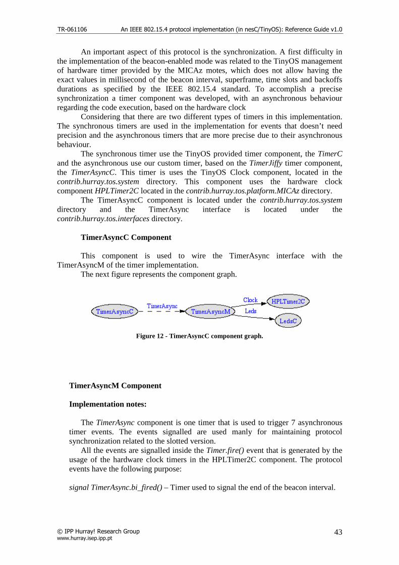
TR-061106 An IEEE 802.15.4 protocol implementation (in nesC/TinyOS): Reference Guide v1.0
© IPP Hurray! Research Group www.hurray.isep.ipp.pt
43
An important aspect of this protocol is the synchronization. A first difficulty in the implementation of the beacon-enabled mode was related to the TinyOS management of hardware timer provided by the MICAz motes, which does not allow having the exact values in millisecond of the beacon interval, superframe, time slots and backoffs durations as specified by the IEEE 802.15.4 standard. To accomplish a precise synchronization a timer component was developed, with an asynchronous behaviour regarding the code execution, based on the hardware clock
Considering that there are two different types of timers in this implementation. The synchronous timers are used in the implementation for events that doesn’t need precision and the asynchronous timers that are more precise due to their asynchronous behaviour.
The synchronous timer use the TinyOS provided timer component, the TimerC and the asynchronous use our custom timer, based on the TimerJiffy timer component, the TimerAsyncC. This timer is uses the TinyOS Clock component, located in the contrib.hurray.tos.system directory. This component uses the hardware clock component HPLTimer2C located in the contrib.hurray.tos.platform.MICAz directory. The TimerAsyncC component is located under the contrib.hurray.tos.system directory and the TimerAsync interface is located under the contrib.hurray.tos.interfaces directory. TimerAsyncC Component
This component is used to wire the TimerAsync interface with the
TimerAsyncM of the timer implementation. The next figure represents the component graph.
Figure 12 - TimerAsyncC component graph.
TimerAsyncM Component Implementation notes: The TimerAsync component is one timer that is used to trigger 7 asynchronous timer events. The events signalled are used manly for maintaining protocol synchronization related to the slotted version. All the events are signalled inside the Timer.fire() event that is generated by the usage of the hardware clock timers in the HPLTimer2C component. The protocol events have the following purpose: signal TimerAsync.bi_fired() – Timer used to signal the end of the beacon interval.

TR-061106 An IEEE 802.15.4 protocol implementation (in nesC/TinyOS): Reference Guide v1.0
© IPP Hurray! Research Group www.hurray.isep.ipp.pt
44
signal TimerAsync.before_bi_fired() – Timer used to signal a time defined constant (BEFORE_BI_INTERVAL) before the beacon interval fired. This is used to turn the transceiver on before the beacon interval fires so that if the device is a pan coordinator the transceiver will be ready to transmit the beacon and if the device is a normal node the transceiver will be ready to receive the beacon. signal TimerAsync.sd_fired() – Timer used to signal the end of the superframe duration. This is used for the device to enter the sleep period (if applied) It’s also used to disable the time slot and backoffs events because during the sleep period there is no activity (if applied). signal TimerAsync.time_slot_fired() - Timer used to signal each time slot. This is used for the GTS mechanism. signal TimerAsync.before_time_slot_fired() – Timer used to signal a time defined constant (BEFORE_BB_INTERVAL) before the time slot fired. This is used to switch the transceiver state before each time slot so that the transceiver is ready to transmit/receive when the time slot starts.
signal TimerAsync.backoff_fired() – Timer used to signal each backoff. This is used for the CSMA/CA algorithm. signal TimerAsync.sfd_fired() – Timer used to signal the start-of-frame delimiter upon the arrival of data. This is used to know exactly when the transceiver starts receiving data and is prior to the FIFO interrupt that is triggered only when the full length of the frame is received. The next figure represents the timer events in the superframe structure.
Figure 13 - Timer events in superframe structure.
This timer component is based on the hardware clock timer configuration defined in two constants:
• SCALE – This constant defines the scale division of the ATMEL microprocessor.
• INTERVAL – This constant defines the number of clock ticks per clock
firing.

TR-061106 An IEEE 802.15.4 protocol implementation (in nesC/TinyOS): Reference Guide v1.0
© IPP Hurray! Research Group www.hurray.isep.ipp.pt
45
The clock tick granularity of the MICAz mote that best fit our requirements is equal
to 69.54 microseconds, which approximately corresponds to four symbols (configuration with SCALE equal to 4 and INTERVAL equal to 1). In fact, the four symbols duration have a theoretical value of 64 microseconds which leads to a cumulative effect on the discrepancy with theoretically values of beacon interval, superframe durations and time slot durations in millisecond for high superframe and beacon orders. For instance, the theoretical time of a superframe duration with SO=3 is equal to 122.88 ms, while it is equal to 133.36 ms using the MICAz motes and the TinyOS time management of the clock granularity.
MICAZ
Effective Teorical Backoff Symbols 20 20 Symbol Duration (us) 17,362 16 Backoff Duration (us) 347,24 320 Granularity (us) 69,54 64 Backoff Clock Ticks 5 5
Table 9 - MICAz clock ticks granularity comparison.
MICAz Time Slot Durations (Effective Values)
SO Symbols Backoff Periods Timeslot Duration (us) Clock Ticks 0 60 3 1041,72 15 1 120 6 2083,44 30 2 240 12 4166,88 60 3 480 24 8333,76 120 4 960 48 16667,52 240 5 1920 96 33335,04 479 6 3840 192 66670,08 959 7 7680 384 133340,16 1917 8 15360 768 266680,32 3835 9 30720 1536 533360,64 7670
10 61440 3072 1066721,28 15340 11 122880 6144 2133442,56 30679 12 245760 12288 4266885,12 61359 13 491520 24576 8533770,24 122717 14 983040 49152 17067540,48 245435
Table 10 - MICAz time slot durations - Effective values.
MICAz Time Slot Durations (Theoretical Values)
SO Symbols Backoff Periods Timeslot Duration (us) Clock Ticks 0 60 3 960 15 1 120 6 1920 30 2 240 12 3840 60 3 480 24 7680 120 4 960 48 15360 240 5 1920 96 30720 480 6 3840 192 61440 960

TR-061106 An IEEE 802.15.4 protocol implementation (in nesC/TinyOS): Reference Guide v1.0
© IPP Hurray! Research Group www.hurray.isep.ipp.pt
46
7 7680 384 122880 1920 8 15360 768 245760 3840 9 30720 1536 491520 7680
10 61440 3072 983040 15360 11 122880 6144 1966080 30720 12 245760 12288 3932160 61440 13 491520 24576 7864320 122880 14 983040 49152 15728640 245760
Table 11 - MICAz time slot durations - Theoretical values.
MICAz Beacon Interval Durations (Effective Values)
BO Symbols Backoff Periods Duration (us) Clock Ticks 0 960 48 16667,52 240 1 1920 96 33335,04 479 2 3840 192 66670,08 959 3 7680 384 133340,16 1917 4 15360 768 266680,32 3835 5 30720 1536 533360,64 7670 6 61440 3072 1066721,28 15340 7 122880 6144 2133442,56 30679 8 245760 12288 4266885,12 61359 9 491520 24576 8533770,24 122717
10 983040 49152 17067540,48 245435 11 1966080 98304 34135080,96 490870 12 3932160 196608 68270161,92 981739 13 7864320 393216 136540323,8 1963479 14 15728640 786432 273080647,7 3926958
Table 12 - MICAz beacon interval durations - Effective values.
MICAz Beacon Interval Durations (Theoretical Values)
BO Symbols Backoff Periods Duration (us) Clock Ticks 0 960 48 15360 240 1 1920 96 30720 480 2 3840 192 61440 960 3 7680 384 122880 1920 4 15360 768 245760 3840 5 30720 1536 491520 7680 6 61440 3072 983040 15360 7 122880 6144 1966080 30720 8 245760 12288 3932160 61440 9 491520 24576 7864320 122880
10 983040 49152 15728640 245760 11 1966080 98304 31457280 491520 12 3932160 196608 62914560 983040 13 7864320 393216 125829120 1966080 14 15728640 786432 251658240 3932160
Table 13 - MICAz beacon interval durations - Theoretical values.

TR-061106 An IEEE 802.15.4 protocol implementation (in nesC/TinyOS): Reference Guide v1.0
© IPP Hurray! Research Group www.hurray.isep.ipp.pt
47
Required Interfaces
The required interfaces of the TimerAsyncM component are the following:
• Clock Timer • Leds
Provided Interfaces The provided interfaces of the TimerAsyncM component are the following:
• TimerAsync
Variables
• uint32_t ticks_counter – current number of clock ticks on each beacon interval. • uint32_t bi_ticks – number of clock ticks needed to reach the beacon interval
boundary. • uint32_t bi_backoff_periods – number of backoffs in one beacon interval. • uint32_t before_bi_ticks – number of clock ticks needed to reach the boundary
defined by the bi_ticks – BEFORE_BI_INTERVAL (constant). • uint32_t sd_ticks – number of clock ticks needed to reach the superframe
duration interval boundary. • uint32_t time_slot_backoff_periods – number of backoffs in one time slot. • uint32_t time_slot_ticks –total number of clock ticks needed to reach the beacon
interval boundary. • uint32_t before_time_slot_ticks - number of clock ticks needed to reach the
boundary defined by the bi_ticks – BEFORE_BB_INTERVAL (constant). • uint32_t time_slot_tick_next_fire – number of clock ticks needed to reach the
next time slot boundary. • uint32_t backoff_symbols – number of symbols in one backoff. • uint32_t backoff_ticks – number of clock ticks in one backoff. • uint32_t backoff_ticks_counter – current number of clock ticks on each backoff. • uint8_t current_time_slot – current time slot number. • uint32_t current_number_backoff_on_time_slot – current backoff number on
each time slot. • uint32_t current_number_backoff – current number of backoff on each beacon
interval. • bool backoffs – enable/disable backoff events . • uint8_t previous_sfd – temporary variable that stores the SFD pin reading . • uint8_t current_sfd – temporary variable that stores the SFD pin reading. • uint32_t process_frame_tick_counter – current number of clock ticks needed to
fully receive a data frame. • uint32_t total_tick_counter – current number of clock ticks.
Function description
async command result_t TimerAsync.start (void)
TR-061106 An IEEE 802.15.4 protocol implementation (in nesC/TinyOS): Reference Guide v1.0
© IPP Hurray! Research Group www.hurray.isep.ipp.pt
48
Command used to start the component. command result_t TimerAsync.init (void) Command used in the initialization of the component. async command result_t TimerAsync.stop (void) Command used to stop the component. async command result_t TimerAsync.reset (void) Command used to reset the global timer variable. This function zeroes the tick_counter variable. async command result_t TimerAsync.reset_process_frame_tick_counter (void) Command used to reset the process frame timer variable. This function zeroes the process_frame_tick_counter variable. async command uint8_t TimerAsync.reset_start (uint32_t start_ticks) Command used to reset the global timer variable. This function initializes the tick_counter variable with the values of the start_ticks argument. async command result_t TimerAsync.set_bi_sd (uint32_t bi_symbols, uint32_t sd_symbols) Command used to set the duration, in symbols, of the beacon interval and superframe. async command result_t TimerAsync.set_backoff_symbols (uint8_t Backoff_Duration_Symbols) Command used to set the duration, in symbols, of the backoff interval. async command result_t TimerAsync.set_enable_backoffs (bool enable) Command used to enable/disable the backoff events interrupts. async command uint32_t TimerAsync.get_current_ticks (void) Command used to read the current_ticks variable. async command uint32_t TimerAsync.get_sd_ticks (void) Command used to read the sd_ticks variable. async command uint32_t TimerAsync.get_bi_ticks (void)
Command used to read the bi_ticks variable.
async command uint32_t TimerAsync.get_backoff_ticks (void) Command used to read the backofft_ticks variable.
async command uint32_t TimerAsync.get_time_slot_ticks (void) Command used to read the time_slot_ticks variable. async command uint32_t TimerAsync.get_current_number_backoff (void)
Command used to read the curren_number_backoff variable.

TR-061106 An IEEE 802.15.4 protocol implementation (in nesC/TinyOS): Reference Guide v1.0
© IPP Hurray! Research Group www.hurray.isep.ipp.pt
49
async command uint32_t TimerAsync.get_time_slot_backoff_periods (void) Command used to read the time_slot_backoff_periods variable.
async command uint32_t TimerAsync.get_current_time_slot (void) Command used to read the current_time_slot variable. async command uint32_t TimerAsync.get_current_number_backoff_on_time_slot (void) Command used to read the current_number_backoff_on_time_slot variable. async command uint32_t TimerAsync.get_total_tick_counter (void) Command used to read the total_tick_counter variable. async command uint32_t TimerAsync.get_process_frame_tick_counter (void) Command used to read the process_frame_tick_counter variable. async event result_t Timer.fire (void) The Timer.fire event is triggered by the Clock component if the interrupts notification is enabled. The TimerAsync module maintains several variables in order to create as many timers as needed based on one event fired. The next diagram represents the computation flow chart for every timer fired event.

TR-061106 An IEEE 802.15.4 protocol implementation (in nesC/TinyOS): Reference Guide v1.0
© IPP Hurray! Research Group www.hurray.isep.ipp.pt
50
Figure 14- Timer.fire flow chat of the TimerAsync component.
TimerAsync Interface This component exposes the function implemented in the TimerAsyncM and is used to wire the MacM to the TimerAsyncC. The commands provided by this interface are the following:
• result_t start(void) • result_t stop(void) • result_t init(void)

TR-061106 An IEEE 802.15.4 protocol implementation (in nesC/TinyOS): Reference Guide v1.0
© IPP Hurray! Research Group www.hurray.isep.ipp.pt
51
• uint32_t get_current_ticks(void) • uint32_t get_sd_ticks(void) • uint32_t get_bi_ticks(void) • result_t reset(void) • uint8_t reset_start(uint32_t start_ticks) • uint32_t get_time_slot_ticks(void) • result_t set_backoff_symbols(uint8_t symbols) • uint32_t get_backoff_ticks(void) • result_t set_enable_backoffs(bool enable_backoffs) • uint32_t get_current_number_backoff(void) • uint32_t get_time_slot_backoff_periods(void) • uint32_t get_current_time_slot(void) • uint32_t get_current_number_backoff_on_time_slot(void) • result_t set_bi_sd(uint32_t bi_symbols, uint32_t sd_symbols) • result_t reset_process_frame_tick_counter(void) • uint32_t get_process_frame_tick_counter(void) • uint32_t get_total_tick_counter(void)
3.5.4. MAC Timer Events
Asynchronous Timers TimerAsync.before_bi_fired() The implementation of this timer is used to turn the transceiver on receive/transmit mode before the bi_fired event. The time before is defined in the TimerAsyncM component in the variable BEFORE_BI_INTERVAL. Because of the time needed to switch the state of the transceiver before sending or receiving data this event tries to minimize that effect. If the device is a coordinator the transceiver is switch to the transmit state so that the beacon frame, that is already constructed, is sent when the bi_fired event is triggered. If the device is not a coordinator the transceiver is switched to the receive mode, therefore, when the bi_fired event is triggered the device will be ready to receive the beacon. The exception in this case is when the beacon order (BO) is equal to the superframe order (SO) and there is no change in the transceiver state.

TR-061106 An IEEE 802.15.4 protocol implementation (in nesC/TinyOS): Reference Guide v1.0
© IPP Hurray! Research Group www.hurray.isep.ipp.pt
52
Figure 15 - before_bi_fired event flow char.
TimerAsync.bi_fired() This event indicates the beginning of a new superframe. If the device is a PAN coordinator it must transmit a beacon, otherwise the device will receive the beacon and process it. The devices that are trying to synchronize with the PAN will have the findabeacon variable enabled. If the device cannot find a beacon after the aMaxBeaconLost, the MAC layer issues the MLME_SYNC_LOSS.indication primitive with the status of MAC_BEACON_LOST. The same procedure occurs if the device is associated with the PAN and tracking the beacons. If the beacon is received, it must be processed before the verifications of these conditions. The synchronization procedures are described in [1 pag 151]. After the synchronization processing, the device calls the send_frame_csma() function to start sending the frames that could be stored in the send_buffer that could not be sent in the last superframe.

TR-061106 An IEEE 802.15.4 protocol implementation (in nesC/TinyOS): Reference Guide v1.0
© IPP Hurray! Research Group www.hurray.isep.ipp.pt
53
Figure 16 - bi_fired event flow chart.
TimerAsync.sd_fired() This timer event indicates the end of the active period of the superframe duration. In this event if the device is not on promiscuous mode and the BO is different than the SO, the transceiver is switched to idle mode. If the device is a coordinator the following maintenance procedures are triggered:
• increment_gts_null() – if there are deallocation GTS descriptors the coordinator need to check their transaction persistence time deciding if the keep showing in the beacon or not;
• check_gts_expiration() – if there are allocated GTS time slots that weren’t used the coordinator must calculate and evaluate their expiration time. If one allocation expires the corresponding GTS descriptor if moved to the deallocated GTS descriptors. This procedure is described in [1 pag 162];
• create_beacon() – the device created the beacon that will be stored until the bi_fired event is triggered.

TR-061106 An IEEE 802.15.4 protocol implementation (in nesC/TinyOS): Reference Guide v1.0
© IPP Hurray! Research Group www.hurray.isep.ipp.pt
54
Figure 17 - sd_fired event flow chart.
TimerAsync.before_time_slot_fired() The implementation of this timer is used to turn the transceiver on receive/transmit mode before the time_slot_fired event. This event is used when the device, being a coordinator or not, has a GTS time slot allocated and when the time slot starts the transceiver is already ready for transmission or reception, depending on the allocated time slot. The time before is defined in the TimerAsyncM component in the variable BEFORE_BB_INTERVAL This event is needed because of the time necessary to switch the state of the transceiver before sending or receiving data. The variables next_on_s_GTS and next_on_r_GTS determine that the next slot will be available for transmission and for reception respectively.

TR-061106 An IEEE 802.15.4 protocol implementation (in nesC/TinyOS): Reference Guide v1.0
© IPP Hurray! Research Group www.hurray.isep.ipp.pt
55
Figure 18 - before_time_slot_fired event flow chart.
TimerAsync.time_slot_fired() This event is triggered on every time slot and is mainly used to perform the GTS management. On every execution of the timer, the number_time_slot variable is maintained with the current time slot information. When the time slot number reaches a GTS slot, the device will try to send data if there are packets to transmit. After the activation of the send mechanism the device will evaluate if the next slot is also a GTS slot. In this event there are two distinct operation modes: the coordinator operation and the non-coordinator operation. The GTS management on these two modes is different, if the device is a coordinator it must be ready to transmit or receive on every GTS slot to and from the appropriate device. If the device is not a coordinator it only needs to check the time slot number, previously allocated on the coordinator and confirmed in the beacon GTS descriptors, and take the appropriate action, transmit data if it has an allocation for transmission or receive data. The s_GTSss and r_GTSss variables indicate the timeslot number of the device allocated send/receive GTS slot. The number_backoff variable keeps count of the number of backoffs in the time slot. For a more detailed explanation about the GTS management refer to the GTS Management section.

TR-061106 An IEEE 802.15.4 protocol implementation (in nesC/TinyOS): Reference Guide v1.0
© IPP Hurray! Research Group www.hurray.isep.ipp.pt
56
Figure 19 - time_slot_fired event flow chart.
TimerAsync.sfd_fired()

TR-061106 An IEEE 802.15.4 protocol implementation (in nesC/TinyOS): Reference Guide v1.0
© IPP Hurray! Research Group www.hurray.isep.ipp.pt
57
This event indicates that the transceiver is starting to receive data. Currently there is no processing in this event. TimerAsync.backoff_fired() This event is triggered on every backoff during the active period of the superframe. The code processing is related to the implementation of the CSMA/CA algorithm. This event maintains the number_backoff variable counting the number of backoffs in the time slot and a number of states that are defined in the functions concerning the CSMA/CA implementation algorithm. For a more detailed explanation about the CSMA/CA implementation refer to the CSMA/CA section. Synchronous Timers T_ResponseWaitTime.fired() This timer event is activated each time the device needs to execute a procedure involving a request command or a response within a defined time frame. This event will trigger if no response is received, executing the appropriate actions depending on the procedure being executed. For example, if the device tries to associate, the coordinator must respond to the request inside the response wait time frame. The constant variable aResponseWaitTime defines the time frame in symbols for a device to receive a response for its request. In the current status of the implementation, the response wait time event is only used when the device wishes to associate with the PAN coordinator. If the device does not receive an association response command, the MAC layer will signal the upper layer by issuing the MLME_ASSOCIATE.confirm primitive with the status of NO_DATA. T_ackwait.fired() This event is triggered when a device sends a transmission requesting an acknowledgment from the destination. The variable mac_PIB.macAckWaitDuration in the MAC PIB defines the maximum wait time in symbols to receive an acknowledgment, before initiate a retransmission or report a transmission failure. The main purpose of this event is to control the data retransmission and inform the upper layer about a possible data transmission failure. The variables used to control the retransmission procedures are the following:
• send_ack_check – variable stating that the current transmission requires an acknowledgment;
• retransmit_count – number of retransmissions of the current frame transmission; • send_indirect_transmission – variable stating that the current transmission is an
indirect transmission and doesn’t require a retransmission if the first transmission fails;
• ack_sequence_number_check – current transmission frame sequence number.

TR-061106 An IEEE 802.15.4 protocol implementation (in nesC/TinyOS): Reference Guide v1.0
© IPP Hurray! Research Group www.hurray.isep.ipp.pt
58
The function send_frame_csma() is used to send the next frame in the send buffer. When the frame is being send the variables send_ack_check, send_indirect_transmission and ack_sequence_number_check are initialized.
Figure 20 - T_ackwait.fired event flow chart.
3.5.5. Frame Construction
The frame formats are composed of a MHR, a MAC payload and a MFR. The
fields of the MHR appear in a fixed order; however, the addressing fields may not be included in all frames. The general MAC frame shall be formatted as illustrated in next figure. [1 pag. 112].

TR-061106 An IEEE 802.15.4 protocol implementation (in nesC/TinyOS): Reference Guide v1.0
© IPP Hurray! Research Group www.hurray.isep.ipp.pt
59
Figure 21 - General MAC frame format.
The structure definitions and structure size constants used to construct all the frames are defined in the frame_format.h file under the contrib.tos.system. In the mac_func.h file there are auxiliary functions used for constructing/retrieving fields that require bit operations. The frame control field is 16 bits length and contains information defining the frame type, addressing fields and other control flags. This field in constructed using the following set function located in the mac_func.h file. uint16_t set_frame_control( uint8_t frame_type, uint8_t security, uint8_t frame_pending, uint8_t ack_request, uint8_t intra_pan, uint8_t dest_addr_mode, uint8_t source_addr_mode) { uint8_t fc_b1=0; uint8_t fc_b2=0; fc_b1 = ( (intra_pan << 6) | (ack_request << 5) | (frame_pending << 4) | (security << 3) | (frame_type << 0) ); fc_b2 = ( (source_addr_mode << 6) | (dest_addr_mode << 2)); return ( (fc_b2 << 8 ) | (fc_b1 << 0) ); }
Code Example 3 - Mac frame control construction function.
Figure 22 - Format of the frame control field.
Because of the variety of combination that can be used in constructing a frame we adopted the strategy of using a generic frame format structure for all frames that we defined as MPDU. The MPDU structure is the following:

TR-061106 An IEEE 802.15.4 protocol implementation (in nesC/TinyOS): Reference Guide v1.0
© IPP Hurray! Research Group www.hurray.isep.ipp.pt
60
typedef struct MPDU {
uint8_t length; uint16_t frame_control; uint8_t seq_num; uint8_t data[121];
}MPDU;
Code Example 4 - MPDU structure definition in the frame_format.h.
The strategy used for the construction of the frame lies on pointing the corresponding structure to the position zero of the 8 bit data array in the MPDU structure and so on, so that the frame is built according to the needs. The constants defined in this file are used for associating the correspondent structure to its byte length. The main problem constructing frames is the number of possible combinations of the Addressing Fields. The definition of these fields is very time consuming due to the different possibilities, especially in the reception of the frame where the device must be prepared to process all the different addressing scenarios. The next graph illustrates the possible combinations with the indication of the address field length in bytes.
INTRA PAN No INTRA PAN
Source Address Field Size (Bytes)
No Short Long No Short Long
No - 2 8 - 4 10 Short 4 6 12 4 8 14 Intra/No intraPAN Destination
Long 8 12 18 10 14 20
Table 14 - Address fields - possible sizes and combinations.
Size (Bytes)
Addressing Short 4 Addressing Long 10
Intra PAN Source Short 2 Intra PAN Source Long 8
Table 15 - Address fields - size reference.
For example (nesC code), if we want to build a data frame with a short destination address and a long source address we have to create first an MPDU variable and its correspondent MPDU type pointer. Then, we also have to create a structure pointer for the short destination and another for the long source addressing fields.
The next code example shows the relevant structure definitions in the frame_format.h relevant for this example.
#define DEST_SHORT_LEN 4 #define SOURCE_LONG_LEN 10 typedef struct dest_short { uint16_t destination_PAN_identifier; uint16_t destination_address;

TR-061106 An IEEE 802.15.4 protocol implementation (in nesC/TinyOS): Reference Guide v1.0
© IPP Hurray! Research Group www.hurray.isep.ipp.pt
61
}dest_short; typedef struct source_long { uint16_t source_PAN_identifier; uint32_t source_address0; uint32_t source_address1; }source_long;
Code Example 5 - frame_format.h structure definition example.
MPDU frame_pkt; MPDU * frame_pkt_ptr; dest_long *dest_long_ptr; source_short *source_short_ptr; frame_pkt_ptr = (MPDU *) &frame_pkt; dest_short_ptr = (dest_short *) &frame_pkt->data[0]; source_long_ptr = (source_long *) &frame_pkt->data[DEST_SHORT_LEN]; frame_pkt->length = data_len + msduLength + MPDU_HEADER_LEN; frame_pkt->frame_control = set_frame_control(TYPE_DATA,0,0,get_txoptions_ack(TxOptions) ,0, SHORT_ADDRESS, LONG_ADDRESS); frame_pkt->seq_num =/*Data Sequence Number*/; dest_short_ptr->destination_PAN_identifier= /*Destination PAN Address*/; dest_short_ptr->destination_address=/*Destination Address*/; source_long_ptr->source_PAN_identifier=/*Source PAN Address*/; source_long_ptr->source_address0=/*Source Address*/; source_long_ptr->source_address1=/*Source Address*/;
Code Example 6 - Data frame construction example.
In the MacM.nc file all the functions that start with create_<something> are used in the construction of frames. The data frame format is illustrated in [1 pag.120], the command frame format in [1 pag.122] and the beacon frame in [1 pag.116].
3.5.6. Beacon Management
Creating Beacon (Coordinators Only) The function create_beacon() is used by the PAN coordinator to construct the beacon frame that will be ready to send in the next bi_fired event, indicating the beginning of a new superframe. The beacon contains information about the PAN, such as beacon intervals, beacon orders and other information included in the superframe specification; information about the allocated/deallocated GTS time slots on the CFP in

TR-061106 An IEEE 802.15.4 protocol implementation (in nesC/TinyOS): Reference Guide v1.0
© IPP Hurray! Research Group www.hurray.isep.ipp.pt
62
the GTS fields; information about the devices that have pending data in the coordinator in the pending address fields and other data in the beacon payload. The next figure represents the structure of a beacon [1 pag. 116]
Figure 23 - Beacon frame format
The beacon frame is divided into two parts: the MHR that contains the frame control field containing the general frame information, the beacon sequence number and the addressing fields; and the specific beacon MAC payload that contains the superframe specification field, the GTS fields, pending address fields and optional beacon payload data. The superframe specification field, as seen in the next figure, can be constructed using the function set_superframe_specification implemented in the mac_func.h file and the values can be retrieved with the respective get functions implemented in the same file.
Figure 24 - Superframe Specification Format
The header of the GTS fields is composed by three fields: the GTS specification with the information of the number of GTS descriptors in the GTS list and the GTS permit; the GTS directions field with the information about the directions of the allocations, if there are GTS descriptor on the list; and the GTS list of descriptors.
Figure 25 - GTS fields format.

TR-061106 An IEEE 802.15.4 protocol implementation (in nesC/TinyOS): Reference Guide v1.0
© IPP Hurray! Research Group www.hurray.isep.ipp.pt
63
Figure 26- GTS specification field format.
Figure 27 - GTS directions field format.
The GTS descriptors contain information about the short address of the devices allocation GTS, the start slot in the CFP and the number of slots allocated. Besides the allocated GTS slots, the GTS descriptors list include the deallocated GTS with the GTS descriptors containing information about the device address and with zero values in the start slot and length.
Figure 28 - GTS descriptor field format.
The pending addresses field contains information of the data stored in the coordinator. This data must be requested by the receiver device in order to be sent. To construct the pending address list the indirect_trans_queue buffer is read and the correspondent address is created for each valid entry.
Figure 29 - Pending addresses field format.

TR-061106 An IEEE 802.15.4 protocol implementation (in nesC/TinyOS): Reference Guide v1.0
© IPP Hurray! Research Group www.hurray.isep.ipp.pt
64
Figure 30 - Pending address specification field format.
The next flow chart represents the steps for building a beacon frame in the create_frame function. The procedure for building the pending addresses list is described in the Pending Data / Indirect Transmission section.

TR-061106 An IEEE 802.15.4 protocol implementation (in nesC/TinyOS): Reference Guide v1.0
© IPP Hurray! Research Group www.hurray.isep.ipp.pt
65
Figure 31 - Beacon creation flow chart.
After the creation of the beacon the frame is stored in the variable mac_beacon_txmpdu and will be ready to send. The creation of the beacon only takes place if the device is a PAN coordinator and after the next higher layer, above the MAC, issues the MLME-START.request primitive. The beacon generation procedure is described in [1 pag.100]. The next figure illustrates the sequence of messages between layers when the PAN coordinator starts the beacon generation [1 pag 180].
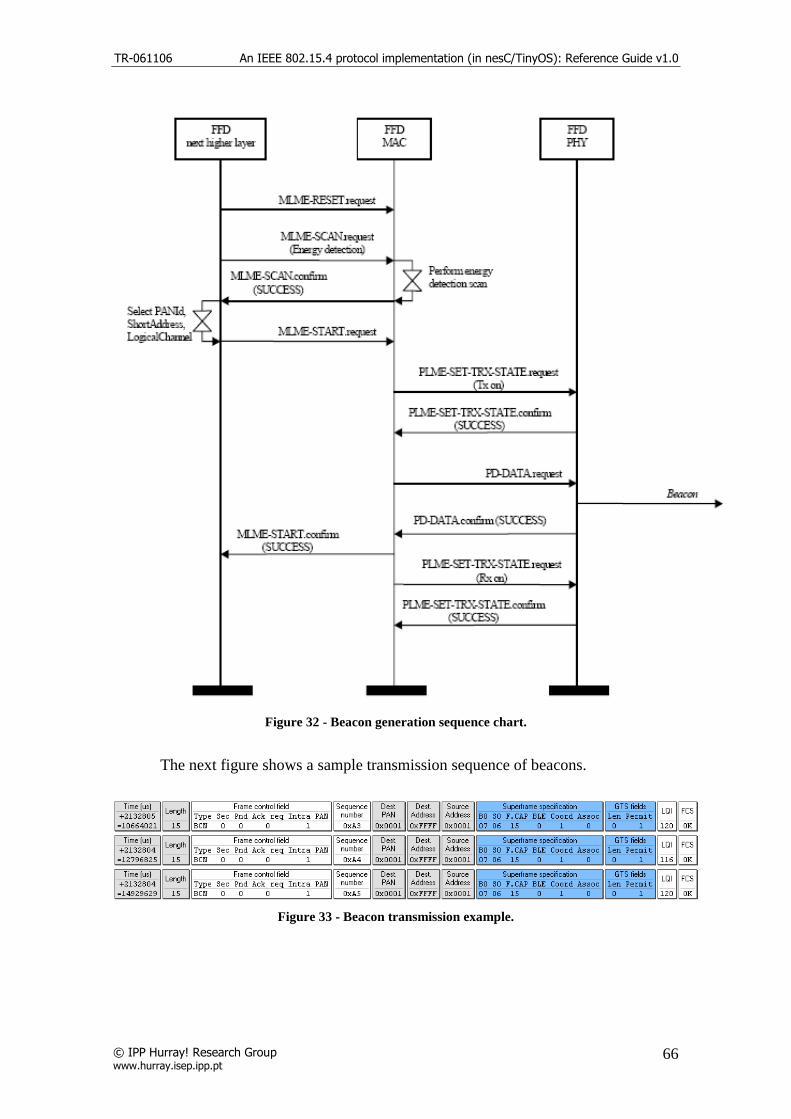
TR-061106 An IEEE 802.15.4 protocol implementation (in nesC/TinyOS): Reference Guide v1.0
© IPP Hurray! Research Group www.hurray.isep.ipp.pt
66
Figure 32 - Beacon generation sequence chart.
The next figure shows a sample transmission sequence of beacons.
Figure 33 - Beacon transmission example.

TR-061106 An IEEE 802.15.4 protocol implementation (in nesC/TinyOS): Reference Guide v1.0
© IPP Hurray! Research Group www.hurray.isep.ipp.pt
67
Processing beacon (Devices) In the beginning of each superframe interval, the devices receive a beacon frame in order to synchronize and to update the PAN information. After the processing of the beacon, the upper layer is signalled with the information retrieved from the beacon processing. The processing of the beacon information is made in the process_beacon(MPDU *packet) function. This processing is divided into the following steps:
1. Processing of the superframe specification field in order to read the values of
the beacon order, the superframe order and the final cap slot; 2. Compute the superframe duration, the beacon interval, the time slot and the
backoff period in symbols; 3. Process the GTS characteristics and, if there are GTS descriptors in the GTS
list, compute each one in order to verify and search the correspondent device address. If the address is present the device evaluates the descriptor information and updates its own GTS information, either for an allocation, deallocation or a confirmation of the current allocation request. This update is very important because the time slot(s) assigned to the device may change due to a reorder of the GTS descriptors on the PAN coordinator;
4. Process the pending addresses information; 5. Build the PAN descriptor information to inform the upper layer; 6. Synchronize the device asynchronous timer with the PAN coordinator. In
order to have a correct synchronization the device must take into account the transmission time, transmission delay, the packet reception time and the packet processing time. On each timer.fire() event in the TimerAsync component a counter is set to zero when the transceiver starts receiving data or the SFD pin goes high. When the device wants to synchronize it reads the SFD counter (process_frame_tick_counter variable in the timer.fire() function) to compute the processing time of the frame. The synchronization also takes into account the possible variables so that the internal time of the TimerAsync component can be set with the appropriate start value.
7. Signal the upper layer using the MLME_BEACON_NOTIFY.indication primitive with the PAN descriptor information.
The MLME_BEACON_NOTIFY.indication primitive has the following semantic [1 pag 75]: event result_t indication( uint8_t BSN, PANDescriptor pan_descriptor, uint8_t PenAddrSpec, uint8_t AddrList, uint8_t sduLength, uint8_t sdu[]);
Code Example 7 - MLME_BEACON_NOTIFY indication event .
The BSN is the beacon sequence number, the pan_descriptor is a structure with the description of the PAN, the PenAddrSpec contains the pending addresses specification field and the AddrList the address list, the sduLength is the number of
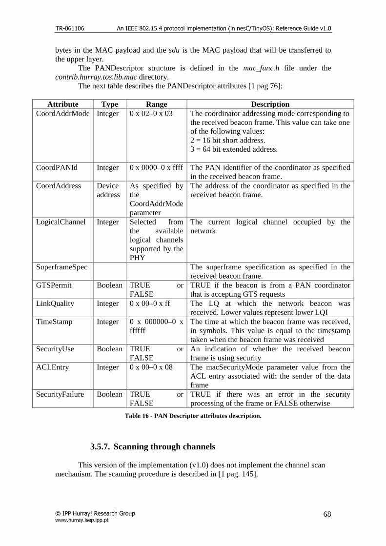
TR-061106 An IEEE 802.15.4 protocol implementation (in nesC/TinyOS): Reference Guide v1.0
© IPP Hurray! Research Group www.hurray.isep.ipp.pt
68
bytes in the MAC payload and the sdu is the MAC payload that will be transferred to the upper layer. The PANDescriptor structure is defined in the mac_func.h file under the contrib.hurray.tos.lib.mac directory. The next table describes the PANDescriptor attributes [1 pag 76]:
Attribute Type Range Description CoordAddrMode Integer 0 x 02–0 x 03 The coordinator addressing mode corresponding to
the received beacon frame. This value can take one of the following values: 2 = 16 bit short address. 3 = 64 bit extended address.
CoordPANId Integer 0 x 0000–0 x ffff The PAN identifier of the coordinator as specified in the received beacon frame.
CoordAddress Device address
As specified by the CoordAddrMode parameter
The address of the coordinator as specified in the received beacon frame.
LogicalChannel Integer Selected from the available logical channels supported by the PHY
The current logical channel occupied by the network.
SuperframeSpec The superframe specification as specified in the received beacon frame.
GTSPermit Boolean TRUE or FALSE
TRUE if the beacon is from a PAN coordinator that is accepting GTS requests
LinkQuality Integer 0 x 00–0 x ff The LQ at which the network beacon was received. Lower values represent lower LQI
TimeStamp Integer 0 x 000000–0 x ffffff
The time at which the beacon frame was received, in symbols. This value is equal to the timestamp taken when the beacon frame was received
SecurityUse Boolean TRUE or FALSE
An indication of whether the received beacon frame is using security
ACLEntry Integer 0 x 00–0 x 08 The macSecurityMode parameter value from the ACL entry associated with the sender of the data frame
SecurityFailure Boolean TRUE or FALSE
TRUE if there was an error in the security processing of the frame or FALSE otherwise
Table 16 - PAN Descriptor attributes description.
3.5.7. Scanning through channels
This version of the implementation (v1.0) does not implement the channel scan mechanism. The scanning procedure is described in [1 pag. 145].

TR-061106 An IEEE 802.15.4 protocol implementation (in nesC/TinyOS): Reference Guide v1.0
© IPP Hurray! Research Group www.hurray.isep.ipp.pt
69
3.5.8. Association and Disassociation
The association and disassociation procedures are described in [1 pag 149]. The association procedure occurs when the device wants to associate with a PAN coordinator. To proceed with the association the device must scan all the channels for radio transmissions, so that it can select the most suitable PAN. The association is necessary if the device wants to transmit data in the PAN. As a result of the association mechanism, the device is assigned with a short address allowing it to transmit in the PAN and, depending on the network topology, transmit to other PANs and devices. The association request frame command is constructed in the create_association_request_cmd function that is called after the upper layer issue the MLME_ASSOCIATE.request primitive. Besides the standard MAC frame fields, the frame has an addressing field, a command frame identifier field and the capability information of the device. The frame is illustrated in the next figure [1 pag 124]:
Figure 34 - Association request frame format.
The capability information field, as seen in the next figure, can be constructed using the function set_capability_information implemented in the mac_func.h file.
Figure 35 - Capability information field format.
Upon the reception of the association request command frame, the coordinator will process the command in the indication_cmd function that will signal the upper layer using the MLME_ASSOCIATE.indication primitive. The upper layer will process the request and will issue the MAC layer with the MLME_ASSOCIATE.request primitive stating the result of the request. If the request is successful the coordination will call the create_association_response_cmd function in order to construct the association response command. The command is stored in the indirect transmission buffer (indirect_trans_queue) and will be transmitted after a data request from the associating device. Besides the update of the MAC PIB, the MAC layer of the device stores the association parameters in the following variables.
• uint8_t a_LogicalChannel – Logical channel of the PAN; • uint8_t a_CoordAddrMode – Coordination address mode;
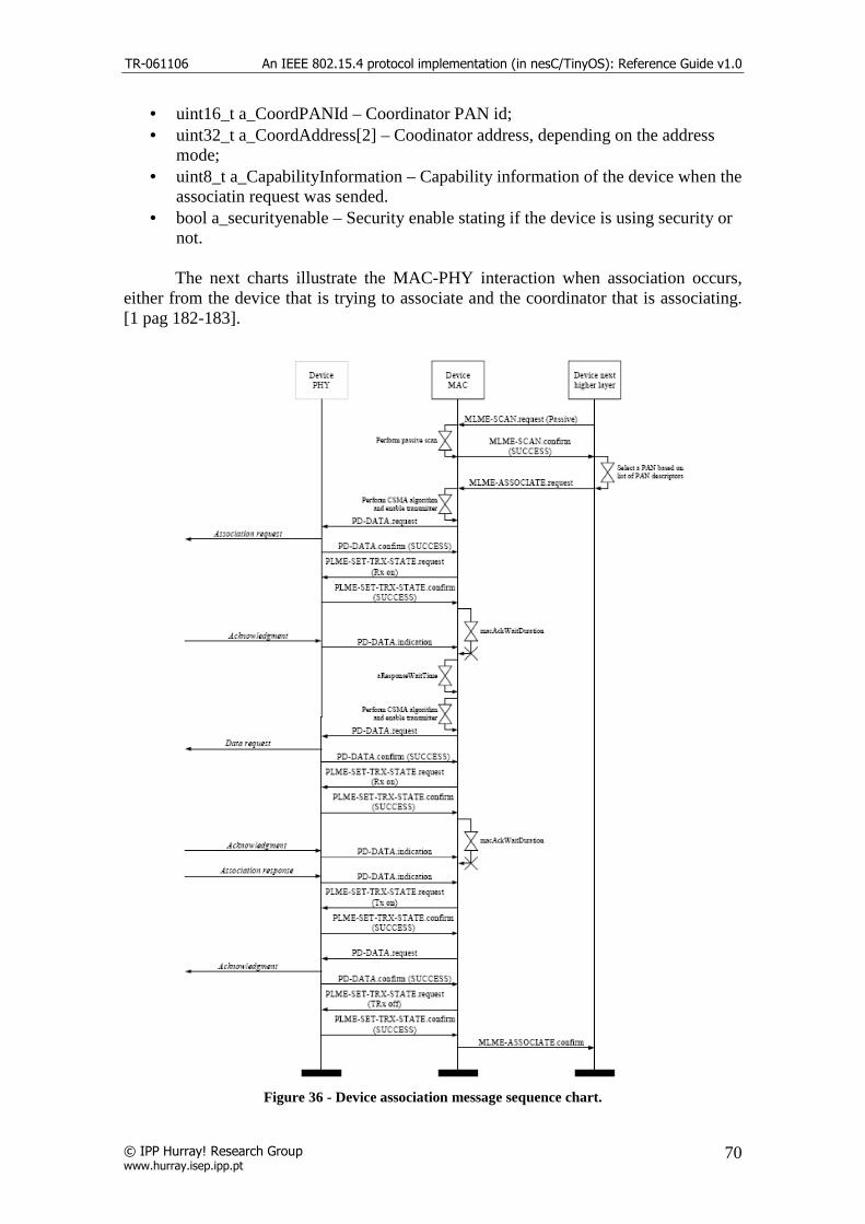
TR-061106 An IEEE 802.15.4 protocol implementation (in nesC/TinyOS): Reference Guide v1.0
© IPP Hurray! Research Group www.hurray.isep.ipp.pt
70
• uint16_t a_CoordPANId – Coordinator PAN id; • uint32_t a_CoordAddress[2] – Coodinator address, depending on the address
mode; • uint8_t a_CapabilityInformation – Capability information of the device when the
associatin request was sended. • bool a_securityenable – Security enable stating if the device is using security or
not. The next charts illustrate the MAC-PHY interaction when association occurs, either from the device that is trying to associate and the coordinator that is associating. [1 pag 182-183].
Figure 36 - Device association message sequence chart.

TR-061106 An IEEE 802.15.4 protocol implementation (in nesC/TinyOS): Reference Guide v1.0
© IPP Hurray! Research Group www.hurray.isep.ipp.pt
71
Figure 37 - Coordinator association message sequence chart.
The next figure shows a sample transmission sequence of a successful association request followed by a data transmission.

TR-061106 An IEEE 802.15.4 protocol implementation (in nesC/TinyOS): Reference Guide v1.0
© IPP Hurray! Research Group www.hurray.isep.ipp.pt
72
Figure 38 - Association mechanism example.
The disassociation request command frame can be generated either by the device, trying to leave the PAN, or by the coordinator, wishing that the device leaves the PAN. After the disassociation procedure the device will lose its short address and will not be able to communicate in the PAN and the coordinator will update the list of associated devices, but it call still store the device information for a future re-association. The disassociation command frame if constructed in the create_disassociation_notification_cmd function. The next figure shows a sample transmission sequence of a disassociation request.
Figure 39 - Disassociation mechanism example.

TR-061106 An IEEE 802.15.4 protocol implementation (in nesC/TinyOS): Reference Guide v1.0
© IPP Hurray! Research Group www.hurray.isep.ipp.pt
73
3.5.9. CSMA/CA
The CSMA/CA algorithm is used when the device wants to transmit frames within the CAP. The transmission of beacon frames, acknowledgement frames and data frames in the CFP will not use the CSMA/CA algorithm instead they will be send directly without any channel assessment. The CSMA/CA mechanism is described in [1 pag. 144]. The application of the algorithm is illustrated in the following flow chart.

TR-061106 An IEEE 802.15.4 protocol implementation (in nesC/TinyOS): Reference Guide v1.0
© IPP Hurray! Research Group www.hurray.isep.ipp.pt
74
Figure 40 - CSMA/CS algorithm.
The implementation of the CSMA/CA involves several functions and global variables used in conjunction with the TimerAsync.backoff_fired() timer events. The function send_frame_csma is called to start the application of the CSMA/CA mechanism and if the channel is clear and there is data to be send it will

TR-061106 An IEEE 802.15.4 protocol implementation (in nesC/TinyOS): Reference Guide v1.0
© IPP Hurray! Research Group www.hurray.isep.ipp.pt
75
send the frame. If there is no data in the send_buffer, the send procedure will abort. The function send_frame_csma is called in the following cases:
• When a frame is created and it is already in the send buffer ready to be send;
• When the last frame was successfully transmitted and there is still data in the buffer ready to be send;
• In the beginning of the CAP when the TimerAsync.bi_fired() timer event fires;
• In the retransmission of a frame requiring an acknowledgment; • After a failed transmission and there is still data in the buffer ready to be
send. When the function is called, it will check if the device is in the CFP and if there is data ready to be sent. If the conditions check true, the function will set the Boolean variable performing_csma_ca to true, meaning that the application of algorithm is in progress, and will call the perform_csma_ca() function to proceed with the application of the algorithm. Although the receiver of the device is enabled during the channel assessment portion of this algorithm, the device shall discard any frames received during this time. At this point the algorithm is in step 1 (Last figure). The function perform_csma_ca() will choose the application of the slotted or the unslotted version. In the unslotted version the function will call the function init_csma_ca() to initialize the variables NB (number of backoffs) and BE (backoff exponent). The function will also initialize the variable delay_backoff_period with a random value and will set the csma_delay Boolean variable to start the delay mechanism, implemented in the TimerAsync.backoff_fired() timer event. In the slotted version, the function calls the init_csma_ca() to initialize the variables needed for the application of the algorithm, namely the contention window (CW), the number of backoffs (NB) and other auxiliary variables. The backoff exponent (BE) is set depending on the battery life parameter. The boolean variable csma_locate_backoff_boundary is set to true triggering the location on the backoff boundary implemented in the TimerAsync.backoff_fired() timer event. At this point the algorithm is in step 2 (Last figure). The next steps of the algorithm will be triggered in the TimerAsync.backoff_fired() timer event depending on the state of the auxiliary variables of the implementation. The next figure shows the flow chart for the perform_csma_ca() function.

TR-061106 An IEEE 802.15.4 protocol implementation (in nesC/TinyOS): Reference Guide v1.0
© IPP Hurray! Research Group www.hurray.isep.ipp.pt
76
Figure 41 - perform_csma_ca() function flow chart.
The TimerAsync.backoff_fired() timer event will be triggered on every backoff of the CAP and will call the functions start_csma_ca_slotted() / perform_csma_ca_slotted() or perform_csma_ca_unslotted() for the application of the slotted or unslotted version respectively. The auxiliary variables used in the implementation of the timer event are the following:
• csma_delay – Used in the step 2 of the algorithm to trigger the count down of the delay backoff periods;
• csma_cca_backoff_boundary– Used in the step 3 of the algorithm after the delay period is over to perform the channel assessment;
• delay_backoff_period – Number of backoff interval of the delay period; • csma_locate_backoff_boundary – Used to locate the backoff boundary of the
first channel assessment in the slotted version of the algorithm.

TR-061106 An IEEE 802.15.4 protocol implementation (in nesC/TinyOS): Reference Guide v1.0
© IPP Hurray! Research Group www.hurray.isep.ipp.pt
77
Figure 42 - backoff_fired event flow chart.
The slotted version of the algorithm implements two functions; the start_csma_ca_slotted() and the perform_csma_ca_slotted(). The first function is called once when the csma_locate_backoff_boundary is set to 1 and it is to set the delay_backoff_period variable with a random value before entering the step 2 of the algorithm.
Figure 43 – start_csma_ca_slotted() function flow chart.
The function perform_csma_ca_slotted() implements the final steps of the algorithm. This function updates the global variables of the algorithm and sets the timer

TR-061106 An IEEE 802.15.4 protocol implementation (in nesC/TinyOS): Reference Guide v1.0
© IPP Hurray! Research Group www.hurray.isep.ipp.pt
78
auxiliary variables, so that it can be called several times to accomplish the application of the CSMA/CA. The function TOSH_READ_CC_CCA_PIN(), available in TinyOS, is used to perform the clear channel assessment and evaluate if the channel is clear (1) or not (0). The next figure illustrate the operation of the perform_csma_ca_slotted() function.
Figure 44 - perform_csma_ca_slotted() function flow chart.
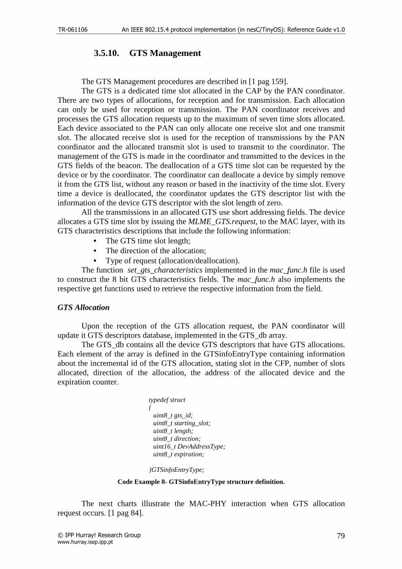
TR-061106 An IEEE 802.15.4 protocol implementation (in nesC/TinyOS): Reference Guide v1.0
© IPP Hurray! Research Group www.hurray.isep.ipp.pt
79
3.5.10. GTS Management
The GTS Management procedures are described in [1 pag 159]. The GTS is a dedicated time slot allocated in the CAP by the PAN coordinator. There are two types of allocations, for reception and for transmission. Each allocation can only be used for reception or transmission. The PAN coordinator receives and processes the GTS allocation requests up to the maximum of seven time slots allocated. Each device associated to the PAN can only allocate one receive slot and one transmit slot. The allocated receive slot is used for the reception of transmissions by the PAN coordinator and the allocated transmit slot is used to transmit to the coordinator. The management of the GTS is made in the coordinator and transmitted to the devices in the GTS fields of the beacon. The deallocation of a GTS time slot can be requested by the device or by the coordinator. The coordinator can deallocate a device by simply remove it from the GTS list, without any reason or based in the inactivity of the time slot. Every time a device is deallocated, the coordinator updates the GTS descriptor list with the information of the device GTS descriptor with the slot length of zero. All the transmissions in an allocated GTS use short addressing fields. The device allocates a GTS time slot by issuing the MLME_GTS.request, to the MAC layer, with its GTS characteristics descriptions that include the following information:
• The GTS time slot length; • The direction of the allocation; • Type of request (allocation/deallocation).
The function set_gts_characteristics implemented in the mac_func.h file is used to construct the 8 bit GTS characteristics fields. The mac_func.h also implements the respective get functions used to retrieve the respective information from the field. GTS Allocation Upon the reception of the GTS allocation request, the PAN coordinator will update it GTS descriptors database, implemented in the GTS_db array. The GTS_db contains all the device GTS descriptors that have GTS allocations. Each element of the array is defined in the GTSinfoEntryType containing information about the incremental id of the GTS allocation, stating slot in the CFP, number of slots allocated, direction of the allocation, the address of the allocated device and the expiration counter.
typedef struct { uint8_t gts_id; uint8_t starting_slot; uint8_t length; uint8_t direction; uint16_t DevAddressType; uint8_t expiration; }GTSinfoEntryType;
Code Example 8- GTSinfoEntryType structure definition.
The next charts illustrate the MAC-PHY interaction when GTS allocation request occurs. [1 pag 84].
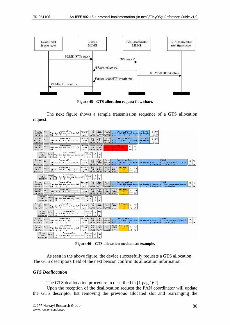
TR-061106 An IEEE 802.15.4 protocol implementation (in nesC/TinyOS): Reference Guide v1.0
© IPP Hurray! Research Group www.hurray.isep.ipp.pt
80
Figure 45 - GTS allocation request flow chart.
The next figure shows a sample transmission sequence of a GTS allocation request.
Figure 46 – GTS allocation mechanism example.
As seen in the above figure, the device successfully requests a GTS allocation. The GTS descriptors field of the next beacon confirm its allocation information. GTS Deallocation The GTS deallocation procedure in described in [1 pag 162]. Upon the reception of the deallocation request the PAN coordinator will update the GTS descriptor list removing the previous allocated slot and rearranging the

TR-061106 An IEEE 802.15.4 protocol implementation (in nesC/TinyOS): Reference Guide v1.0
© IPP Hurray! Research Group www.hurray.isep.ipp.pt
81
remaining allocation starting slots. The arrangement of the time slots is made in the result_t remove_gts_entry(uint16_t DevAddressType) function located in the MAC layer. The arrangement of the CFP consists in shifting right the allocated GTS descriptors witch have a starting slot less that the recent deallocated GTS descriptor and consequently the final_CAP_slot variable is updated. The next figure illustrates an example of this procedure [1 pag. 163].
Figure 47 - CFP defragmentation on GTS deallocations.
In the above figure, the 1st point represent the three allocated GTS. The 2nd point shows the deallocation of the GTS 2 that start on the 10th time slot and with duration of 4 time slots. The final point show the GTS 3 shifted right 4 time slots. The final CAP slot that was 8 with on the 1st point now is 12 on the 3rd. The PAN coordinator will monitor the GTS activity and if there are no transmissions during a defined number of time slots the GTS allocation expires. The expiration occurs if there is no data frame is received and no acknowledgement by the device or the coordinator respectively, on every 2*n superframes. The n is defined as:
• n = 2 (8-macBeaconOrder) , if 0 ≤ macBeaconOrder ≤ 8 • n = 1 , if 9 ≤ macBeaconOrder ≤ 14
The deallocated GTS descriptor will move to the GTS deallocated descriptors database, defined as GTS_db_null and will appear in the beacon with the starting slot
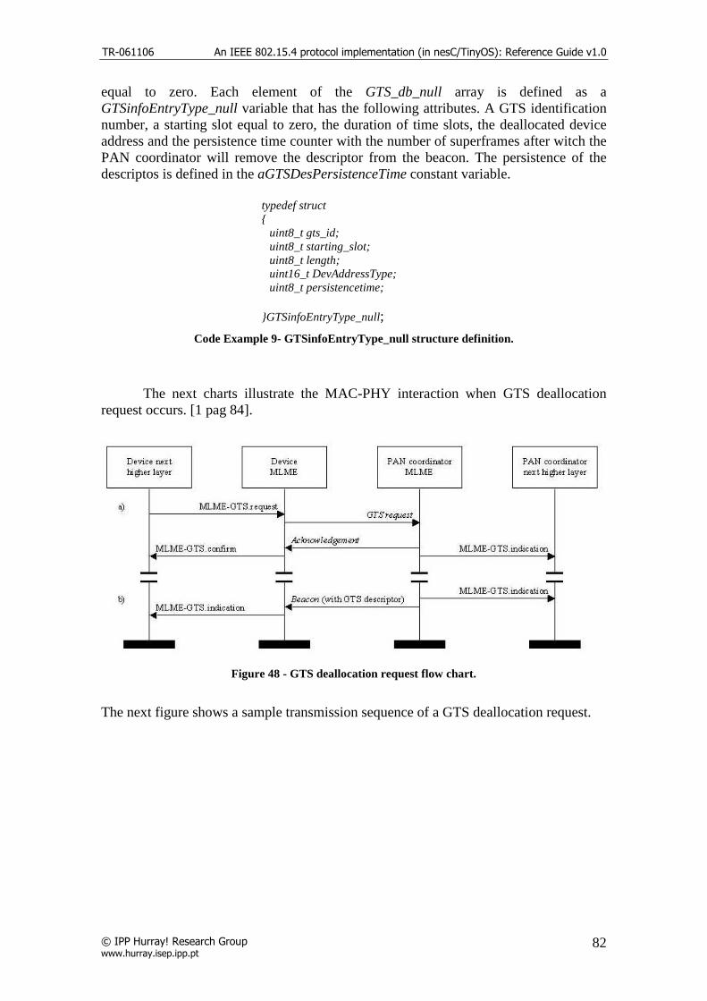
TR-061106 An IEEE 802.15.4 protocol implementation (in nesC/TinyOS): Reference Guide v1.0
© IPP Hurray! Research Group www.hurray.isep.ipp.pt
82
equal to zero. Each element of the GTS_db_null array is defined as a GTSinfoEntryType_null variable that has the following attributes. A GTS identification number, a starting slot equal to zero, the duration of time slots, the deallocated device address and the persistence time counter with the number of superframes after witch the PAN coordinator will remove the descriptor from the beacon. The persistence of the descriptos is defined in the aGTSDesPersistenceTime constant variable.
typedef struct { uint8_t gts_id; uint8_t starting_slot; uint8_t length; uint16_t DevAddressType; uint8_t persistencetime; }GTSinfoEntryType_null;
Code Example 9- GTSinfoEntryType_null structure definition.
The next charts illustrate the MAC-PHY interaction when GTS deallocation request occurs. [1 pag 84].
Figure 48 - GTS deallocation request flow chart.
The next figure shows a sample transmission sequence of a GTS deallocation request.

TR-061106 An IEEE 802.15.4 protocol implementation (in nesC/TinyOS): Reference Guide v1.0
© IPP Hurray! Research Group www.hurray.isep.ipp.pt
83
Figure 49 – GTS deallocation mechanism example.
As seen in the above figure, the device successfully request a GTS deallocation. The next beacon will not contain the deallocated GTS descriptor and the device stops its transmissions. Note that the GTS descriptors in the beacon were rearranged and the device 0x0002 that was transmitting in the 14th slot now is transmitting in the 15th.
3.5.11. Pending data / Indirect Transmissions
The pending data mechanism is used by the PAN coordinator to inform, the devices associated, that they have data pending. The pending data information is described, in the beacon, on the pending data fields. A device will know that it has pending data by examining the beacon payload. The device can request the pending data by sending a data request command frame. Upon receiving the request, the coordinator will search the indirect transmissions buffer for the destination address and send the frame if it finds it. The coordinator ignores the request if it does not find the correct address. The data extraction mechanism is described in [1 pag. 155]. The indirect transmissions are stored in the indirect_trans_queue buffer, on the coordinator, and each message stays in the buffer for a defined amount of superframes. When the coordinator is constructing the beacon, if there are pending addresses to be send, it will construct a list containing there addresses. The following diagram illustrates the construction of the pending addresses list if the indirect_trans_count variable, containing the number of pending addresses, is greater than zero. The variables short_addr_pending and long_addr_pending contains the number of frames with short and long destination addressing fields respectively. The add processes in the next

TR-061106 An IEEE 802.15.4 protocol implementation (in nesC/TinyOS): Reference Guide v1.0
© IPP Hurray! Research Group www.hurray.isep.ipp.pt
84
diagram, indicate that the address is copied to the beacon payload and it length is updated. In the final procedure the pending addresses specification field must be updated with the short and long counters. In the address list, the short addresses must appear first and that is why the buffer is searched twice, the first time is to count and construct the short address list and the second is for the long addresses.
Figure 50 - Pending address list construction diagram.
The next figure shows a sample transmission sequence of data request.
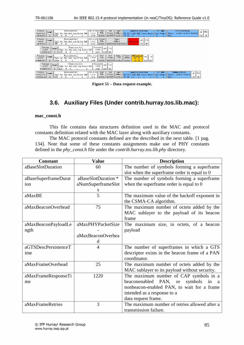
TR-061106 An IEEE 802.15.4 protocol implementation (in nesC/TinyOS): Reference Guide v1.0
© IPP Hurray! Research Group www.hurray.isep.ipp.pt
85
Figure 51 – Data request example.
3.6. Auxiliary Files (Under contrib.hurray.tos.lib.mac): mac_const.h This file contains data structures definition used in the MAC and protocol constants definition related with the MAC layer along with auxiliary constants. The MAC protocol constants defined are the described in the next table. [1 pag. 134]. Note that some of these constants assignments make use of PHY constants defined in the phy_const.h file under the contrib.hurray.tos.lib.phy directory.
Constant Value Description aBaseSlotDuration 60 The number of symbols forming a superframe
slot when the superframe order is equal to 0 aBaseSuperframeDuration
aBaseSlotDuration * aNumSuperframeSlot
s
The number of symbols forming a superframe when the superframe order is equal to 0
aMaxBE 5 The maximum value of the backoff exponent in the CSMA-CA algorithm.
aMaxBeaconOverhead 75 The maximum number of octets added by the MAC sublayer to the payload of its beacon frame
aMaxBeaconPayloadLength
aMaxPHYPacketSize-
aMaxBeaconOverhead
The maximum size, in octets, of a beacon payload
aGTSDescPersistenceTime
4 The number of superframes in which a GTS descriptor exists in the beacon frame of a PAN coordinator.
aMaxFrameOverhead 25 The maximum number of octets added by the MAC sublayer to its payload without security.
aMaxFrameResponseTime
1220 The maximum number of CAP symbols in a beaconenabled PAN, or symbols in a nonbeacon-enabled PAN, to wait for a frame intended as a response to a data request frame.
aMaxFrameRetries 3 The maximum number of retries allowed after a transmission failure.

TR-061106 An IEEE 802.15.4 protocol implementation (in nesC/TinyOS): Reference Guide v1.0
© IPP Hurray! Research Group www.hurray.isep.ipp.pt
86
aMaxLostBeacons 4 The number of consecutive lost beacons that will cause the MAC sublayer of a receiving device to declare a loss of synchronization.
aMaxMACFrameSize aMaxPHYPacketSize-
aMaxFrameOverhead
The maximum number of octets that can be transmitted in the MAC frame payload field.
aMaxSIFSFrameSize 18 The maximum size of an MPDU, in octets, that can be followed by a short interframe spacing (SIFS)
aMinCAPLength 440 The minimum number of symbols forming the CAP. This ensures that MAC commands can still be transferred to devices when GTSs are being used. An exception to this minimum shall be allowed for the accommodation of the temporary increase in the beacon frame length needed to perform GTS maintenance
aMinLIFSPeriod 40 The minimum number of symbols forming a long interframe spacing (LIFS) period.
aMinSIFSPeriod 12 The minimum number of symbols forming a SIFS period.
aNumSuperframeSlots 16 The number of slots contained in any superframe.
aResponseWaitTime 32 * aBaseSuperframeDur
ation
The maximum number of symbols a device shall wait for a response command to be available following a request command.
aUnitBackoffPeriod 20 The number of symbols forming the basic time period used by the CSMA-CA algorithm.
Table 17 - Protocol MAC layer constants description.
The next table describes auxiliary constants used in the MAC layer.
Constant Value Description TYPE_BEACON 0 Beacon type definition. TYPE_DATA 1 Data type definition. TYPE_ACK 2 Acknowledg type definition. TYPE_CMD 3 Command type definition. SHORT_ADDRESS 2 Short address mode definition. LONG_ADDRESS 3 Long address mode definition. RESERVED_ADDRESS 1 Reserved address mode definition. NUMBER_TIME_SLOTS 16 Number of time slots in the superframe. ACK_LENGTH 5 Length of the acknowledge frame. MAX_GTS_BUFFER 7 GTS buffer maximum size. INDIRECT_BUFFER_SIZE 2 Indirect transmission maximum buffer size. RECEIVE_BUFFER_SIZE 5 Receive buffer maximum size. SEND_BUFFER_SIZE 4 Send buffer maximum size GTS_SEND_BUFFER_SIZE 3 GTS buffer maximum size. BACKOFF_PERIOD_MS 0.34724 Duration of a backoff period in milliseconds.

TR-061106 An IEEE 802.15.4 protocol implementation (in nesC/TinyOS): Reference Guide v1.0
© IPP Hurray! Research Group www.hurray.isep.ipp.pt
87
BACKOFF_PERIOD_US 347.24 Duration of a backoff period in microseconds.
Table 18 - MAC layer auxiliary constants description.
The next table describes the structures defined in this file.
Structure Name Attributes Description macPIB uint8_t macAckWaitDuration;
bool macAssociationPermit; bool macAutoRequest; bool macBattLifeExt; uint8_t macBattLifeExtPeriods; uint8_t macBeaconPayload [aMaxBeaconPayloadLength]; uint8_t macBeaconPayloadLenght; uint8_t macBeaconOrder; uint32_t macBeaconTxTime; uint8_t macBSN; uint32_t macCoordExtendedAddress0; uint32_t macCoordExtendedAddress1; uint32_t macCoordShortAddress; uint8_t macDSN; bool macGTSPermit; uint8_t macMaxCSMABackoffs; uint8_t macMinBE; uint16_t macPANId; bool macPromiscuousMode; bool macRxOnWhenIdle; uint32_t macShortAddress; uint8_t macSuperframeOrder; uint32_t macTransactionPersistenceTime;
MAC PAN Information Base. [1 pag. 135]
ACLDescriptor uint32_t ACLExtendedAddress[2]; uint16_t ACLShortAddress; uint16_t ACLPANId; uint8_t ACLSecurityMaterialLength; uint8_t ACLSecurityMaterial; uint8_t ACLSecuritySuite;
ACL entry descriptor [1 pag. 138]. Not Used.
macPIBsec ACLDescriptor macACLEntryDescriptorSet; uint8_t macACLEntryDescriptorSetSize; bool macDefaultSecurity; uint8_t macDefaultSecurityMaterialLength; uint8_t macDefaultSecurityMaterial; uint8_t macDefaultSecuritySuite; uint8_t macSecurityMode;
MAC PAN information Base security Attributes [1 pag. 138]. Not Used.
PANDescriptor uint8_t CoordAddrMode; uint16_t CoordPANId; uint32_t CoordAddress0; uint32_t CoordAddress1; uint8_t LogicalChannel; uint16_t SuperframeSpec;
Description of the PAN, used to store its characteristic [1 pag. 76].

TR-061106 An IEEE 802.15.4 protocol implementation (in nesC/TinyOS): Reference Guide v1.0
© IPP Hurray! Research Group www.hurray.isep.ipp.pt
88
bool GTSPermit; uint8_t LinkQuality; uint32_t TimeStamp; bool SecurityUse; uint8_t ACLEntry; bool SecurityFailure;
GTSinfoEntryType
uint8_t gts_id; uint8_t starting_slot; uint8_t length; uint8_t direction; uint16_t DevAddressType; uint8_t expiration;
Allocated GTS element type of each position of the GTS database maintained by coordinator.
GTSinfoEntryType_null
uint8_t gts_id; uint8_t starting_slot; uint8_t length; uint16_t DevAddressType; uint8_t persistencetime;
Dealocated GTS element type of each position of the GTS database maintained by coordinator.
indirect_transmission_element
uint8_t handler; uint16_t transaction_persistent_time; uint8_t frame[127];
Indirect transmission element of each position in the indirect transmission buffer (indirect_trans_queue).
gts_slot_element uint8_t element_count; uint8_t element_in; uint8_t element_out; uint8_t gts_send_frame_index[GTS_SEND_BUFFER_SIZE];
GTS element of each position in the gts buffer. Used by the PAN coordinator only.
Table 19 - Structure definitions on the mac_const.h file.
mac_enumerations.h
This file contains the enumeration values used in the MAC layer. The following tables describe the enumerations and their usage.
General MAC enumeration description table [1 pag 110].
Enumeration Value Description
MAC_SUCCESS 0x00 The requested operation was completed successfully. For a transmission request, this value indicates a successful transmission.
MAC_BEACON_LOSS 0xE0 The beacon was lost following a synchronization request. MAC_CHANNEL_ACCESS_FAILURE
0xE1 A transmission could not take place due to activity on the channel, i.e., the CSMA-CA mechanism has failed
MAC_DENIED 0xE2 The GTS request has been denied by the PAN coordinator MAC_DISABLE_TRX_FAILURE
0xE3 The attempt to disable the transceiver has failed
MAC_FAILED_SECURITY_CHECK
0xE4 The received frame induces a failed security check according to the security suite.
MAC_FRAME_TOO_L 0xE5 The frame resulting from secure processing has a length that

TR-061106 An IEEE 802.15.4 protocol implementation (in nesC/TinyOS): Reference Guide v1.0
© IPP Hurray! Research Group www.hurray.isep.ipp.pt
89
ONG is greater than aMACMaxFrameSize MAC_INVALID_GTS 0xE6 The requested GTS transmission failed because the specified
GTS either did not have a transmit GTS direction or was not defined
MAC_INVALID_HANDLE
0xE7 A request to purge an MSDU from the transaction queue was made using an MSDU handle that was not found in the transaction table.
MAC_INVALID_PARAMETER
0xE8 A parameter in the primitive is out of the valid range
MAC_NO_ACK 0xE9 No acknowledgment was received after aMaxFrameRetries. MAC_NO_BEACON 0xEA A scan operation failed to find any network beacons MAC_NO_DATA 0xEB No response data were available following a request. MAC_NO_SHORT_ADDRESS
0xEC The operation failed because a short address was not allocated.
MAC_OUT_OF_CAP 0xED A receiver enable request was unsuccessful because it could not be completed within the CAP.
MAC_PAN_ID_CONFLICT
0xEE A PAN identifier conflict has been detected and communicated to the PAN coordinator.
MAC_REALIGNMENT 0xEF A coordinator realignment command has been received MAC_TRANSACTION_EXPIRED
0xF0 The transaction has expired and its information discarded.
MAC_TRANSACTION_OVERFLOW
0xF1 There is no capacity to store the transaction.
MAC_TX_ACTIVE 0xF2 The transceiver was in the transmitter enabled state when the receiver was requested to be enabled
MAC_UNAVAILABLE_KEY
0xF3 The appropriate key is not available in the ACL.
MAC_UNSUPPORTED_ATTRIBUTE
0xF4 A SET/GET request was issued with the identifier of a PIB attribute that is not supported.
Table 20 - General MAC enumeration description.
Disassociation enumeration reasons description table [1 pag 127].
Enumeration Value Description MAC_PAN_COORD_LEAVE 0x01 The disassociation reason was that the coordinator
wishes the device to leave the PAN. MAC_PAN_DEVICE_LEAVE 0x02 The disassociation reason was that the device wishes to
leave the PAN.
Table 21 - Disassociation status enumeration decription.
Command type enumeration description table [1 pag 123].
Enumeration Value Description CMD_ASSOCIATION_REQUEST 0x01 Association request command type. CMD_ASSOCIATION_RESPONSE 0x02 Association response command type. CMD_DISASSOCIATION_NOTIFICATION 0x03 Disassociation notification command
type.
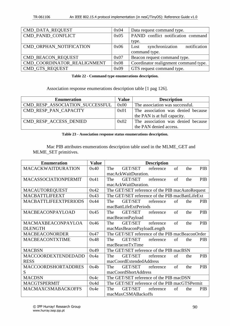
TR-061106 An IEEE 802.15.4 protocol implementation (in nesC/TinyOS): Reference Guide v1.0
© IPP Hurray! Research Group www.hurray.isep.ipp.pt
90
CMD_DATA_REQUEST 0x04 Data request command type. CMD_PANID_CONFLICT 0x05 PANID conflict notification command
type. CMD_ORPHAN_NOTIFICATION 0x06 Lost synchronization notification
command type. CMD_BEACON_REQUEST 0x07 Beacon request command type. CMD_COORDINATOR_REALIGNMENT 0x08 Coordinator realignment command type. CMD_GTS_REQUEST 0x09 GTS request command type.
Table 22 - Command type enumerations description.
Association response enumerations description table [1 pag 126].
Enumeration Value Description CMD_RESP_ASSOCIATION_SUCCESSFUL 0x00 The association was successful. CMD_RESP_PAN_CAPACITY 0x01 The association was denied because
the PAN is at full capacity. CMD_RESP_ACCESS_DENIED 0x02 The association was denied because
the PAN denied access.
Table 23 - Association response status enumerations description.
Mac PIB attributes enumerations description table used in the MLME_GET and MLME_SET primitives.
Enumeration Value Description MACACKWAITDURATION 0x40 The GET/SET reference of the PIB
macAckWaitDuration. MACASSOCIATIONPERMIT 0x41 The GET/SET reference of the PIB
macAckWaitDuration. MACAUTOREQUEST 0x42 The GET/SET reference of the PIB macAutoRequest MACBATTLIFEEXT 0x43 The GET/SET reference of the PIB macBattLifeExt MACBATTLIFEEXTPERIODS 0x44 The GET/SET reference of the PIB
macBattLifeExtPeriods MACBEACONPAYLOAD 0x45 The GET/SET reference of the PIB
macBeaconPayload MACMAXBEACONPAYLOADLENGTH
0x46 The GET/SET reference of the PIB macMaxBeaconPayloadLength
MACBEACONORDER 0x47 The GET/SET reference of the PIB macBeaconOrder MACBEACONTXTIME 0x48 The GET/SET reference of the PIB
macBeaconTxTime MACBSN 0x49 The GET/SET reference of the PIB macBSN MACCOORDEXTENDEDADDRESS
0x4a The GET/SET reference of the PIB macCoordExtendedAddress
MACCOORDSHORTADDRESS
0x4b The GET/SET reference of the PIB macCoordShortAddress
MACDSN 0x4c The GET/SET reference of the PIB macDSN MACGTSPERMIT 0x4d The GET/SET reference of the PIB macGTSPermit MACMAXCSMABACKOFFS 0x4e The GET/SET reference of the PIB
macMaxCSMABackoffs

TR-061106 An IEEE 802.15.4 protocol implementation (in nesC/TinyOS): Reference Guide v1.0
© IPP Hurray! Research Group www.hurray.isep.ipp.pt
91
MACMINBE 0x4f The GET/SET reference of the PIB macMinBE MACPANID 0x50 The GET/SET reference of the PIB macPANId MACPROMISCUOUSMODE 0x51 The GET/SET reference of the PIB
macPromiscuousMode MACRXONWHENIDLE 0x52 The GET/SET reference of the PIB
macRxOnWhenIdle MACSHORTADDRESS 0x53 The GET/SET reference of the PIB macShortAddress MACSUPERFRAMEORDER 0x54 The GET/SET reference of the PIB
macSuperframeOrder. MACTRANSACTIONPERSISTENCETIME
0x55 The GET/SET reference of the PIB macTransactionPercistenceTime
Table 24 - MAC GET/SET reference PIB enumerations description.
GTS direction enumerations description table.
Enumeration Value Description
GTS_TX_ONLY 0x00 GTS direction from device to coordinator. GTS_RX_ONLY 0x01 GTS direction from coordinator to device
Table 25 - GTS direction enumeration descriptions.
Auxiliary Files (Under contrib.hurray.tos.system): frame_format.h This file contains the frame structure definitions. All the frames structures used by the protocol, being command, data, acknowledgment and beacon frames are defined in this file. The next table describes the structures defined in this file:
Structure Name Attributes Description MPDU uint8_t length;
uint16_t frame_control; uint8_t seq_num; uint8_t data[121];
beacon_addr_short uint16_t destination_PAN_identifier; uint16_t destination_address; uint16_t source_address; uint16_t superframe_specification;
beacon_struct uint8_t length; uint16_t frame_control; uint8_t seq_num; uint16_t source_PAN_identifier; uint16_t destination_address; uint16_t source_address; uint16_t superframe_specification;
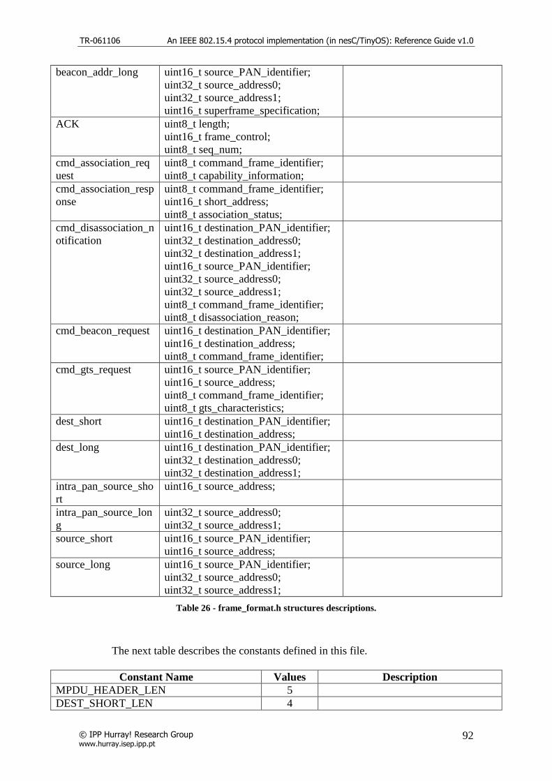
TR-061106 An IEEE 802.15.4 protocol implementation (in nesC/TinyOS): Reference Guide v1.0
© IPP Hurray! Research Group www.hurray.isep.ipp.pt
92
beacon_addr_long uint16_t source_PAN_identifier; uint32_t source_address0; uint32_t source_address1; uint16_t superframe_specification;
ACK uint8_t length; uint16_t frame_control; uint8_t seq_num;
cmd_association_request
uint8_t command_frame_identifier; uint8_t capability_information;
cmd_association_response
uint8_t command_frame_identifier; uint16_t short_address; uint8_t association_status;
cmd_disassociation_notification
uint16_t destination_PAN_identifier; uint32_t destination_address0; uint32_t destination_address1; uint16_t source_PAN_identifier; uint32_t source_address0; uint32_t source_address1; uint8_t command_frame_identifier; uint8_t disassociation_reason;
cmd_beacon_request uint16_t destination_PAN_identifier; uint16_t destination_address; uint8_t command_frame_identifier;
cmd_gts_request uint16_t source_PAN_identifier; uint16_t source_address; uint8_t command_frame_identifier; uint8_t gts_characteristics;
dest_short uint16_t destination_PAN_identifier; uint16_t destination_address;
dest_long uint16_t destination_PAN_identifier; uint32_t destination_address0; uint32_t destination_address1;
intra_pan_source_short
uint16_t source_address;
intra_pan_source_long
uint32_t source_address0; uint32_t source_address1;
source_short uint16_t source_PAN_identifier; uint16_t source_address;
source_long uint16_t source_PAN_identifier; uint32_t source_address0; uint32_t source_address1;
Table 26 - frame_format.h structures descriptions.
The next table describes the constants defined in this file.
Constant Name Values Description MPDU_HEADER_LEN 5 DEST_SHORT_LEN 4

TR-061106 An IEEE 802.15.4 protocol implementation (in nesC/TinyOS): Reference Guide v1.0
© IPP Hurray! Research Group www.hurray.isep.ipp.pt
93
DEST_LONG_LEN 10 INTRA_PAN_SOURCE_SHORT_LEN 2 INTRA_PAN_SOURCE_LONG_LEN 8 SOURCE_SHORT_LEN 4 SOURCE_LONG_LEN 10
Table 27 - frame_format.h constants descriptions.
mac_func.h This file contains auxiliary functions used in the implementation of the protocol. Some functions are used in the construct or retrieve some particular fields in the frame construction, like the frame control field, that require bit operations. The functions defined are the following: uint8_t set_capability_information(uint8_t alternate_PAN_coordinator, uint8_t device_type, uint8_t power_source, uint8_t receiver_on_when_idle, uint8_t security, uint8_t allocate_address) Function used to build the 8 bit capability information of the device requesting an association. uint16_t set_frame_control(uint8_t frame_type,uint8_t security,uint8_t frame_pending,uint8_t ack_request,uint8_t intra_pan,uint8_t dest_addr_mode,uint8_t source_addr_mode) Function used to build the frame control of the MAC frames. uint8_t get_frame_control_dest_addr(uint16_t frame_control) Function used to return the type of destination address specified in the frame control. uint8_t get_frame_control_source_addr(uint16_t frame_control) Function used to return the type of source address specified in the frame control. bool get_security(uint8_t frame_control) Function used to return the security parameter specified in the frame control. bool get_frame_pending(uint8_t frame_control) Function used to return the frame pending parameter specified in the frame control. bool get_ack_request(uint8_t frame_control) Function used to return the acknowledge request parameter specified in the frame control. bool get_intra_pan(uint8_t frame_control) Function used to return the Intra PAN request parameter specified in the frame control.
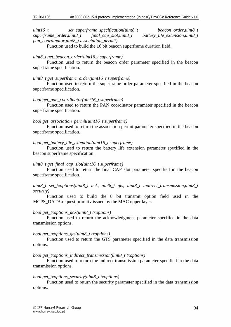
TR-061106 An IEEE 802.15.4 protocol implementation (in nesC/TinyOS): Reference Guide v1.0
© IPP Hurray! Research Group www.hurray.isep.ipp.pt
94
uint16_t set_superframe_specification(uint8_t beacon_order,uint8_t superframe_order,uint8_t final_cap_slot,uint8_t battery_life_extension,uint8_t pan_coordinator,uint8_t association_permit) Function used to build the 16 bit beacon superframe duration field. uint8_t get_beacon_order(uint16_t superframe) Function used to return the beacon order parameter specified in the beacon superframe specification. uint8_t get_superframe_order(uint16_t superframe) Function used to return the superframe order parameter specified in the beacon superframe specification. bool get_pan_coordinator(uint16_t superframe) Function used to return the PAN coordinator parameter specified in the beacon superframe specification. bool get_association_permit(uint16_t superframe) Function used to return the association permit parameter specified in the beacon superframe specification. bool get_battery_life_extention(uint16_t superframe) Function used to return the battery life extension parameter specified in the beacon superframe specification. uint8_t get_final_cap_slot(uint16_t superframe) Function used to return the final CAP slot parameter specified in the beacon superframe specification. uint8_t set_txoptions(uint8_t ack, uint8_t gts, uint8_t indirect_transmission,uint8_t security) Function used to build the 8 bit transmit option field used in the MCPS_DATA.request primitiv issued by the MAC upper layer. bool get_txoptions_ack(uint8_t txoptions) Function used to return the acknowledgment parameter specified in the data transmission options. bool get_txoptions_gts(uint8_t txoptions) Function used to return the GTS parameter specified in the data transmission options. bool get_txoptions_indirect_transmission(uint8_t txoptions) Function used to return the indirect transmission parameter specified in the data transmission options. bool get_txoptions_security(uint8_t txoptions) Function used to return the security parameter specified in the data transmission options.

TR-061106 An IEEE 802.15.4 protocol implementation (in nesC/TinyOS): Reference Guide v1.0
© IPP Hurray! Research Group www.hurray.isep.ipp.pt
95
uint8_t set_pending_address_specification(uint8_t number_short, uint8_t number_extended) Function used to build the pending addresses specification fields used in the beacon payload uint8_t get_number_short(uint8_t pending_specification) Function used to return the number of short addresses of the pending addresses list. uint8_t get_number_extended(uint8_t pending_specification) Function used to return the number of extended addresses of the pending addresses list. uint8_t set_gts_specification(uint8_t gts_descriptor_count, uint8_t gts_permit) Function used to build the 8 bit GTS specification field included in the beacon payload. uint8_t get_gts_permit(uint8_t gts_specification) Function used to return the GTS permit parameter of the GTS specification field. uint8_t set_gts_descriptor(uint8_t GTS_starting_slot, uint8_t GTS_length) Function used to build the 8 bit allocation/ deallocation device descriptor that is included in the beacon GTS descriptor list.. uint8_t get_gts_descriptor_len(uint8_t gts_des_part) Function used to return the length parameter of the GTS descriptor. uint8_t get_gts_descriptor_ss(uint8_t gts_des_part) Function used to return the start slot parameter of the GTS descriptor. uint8_t set_gts_characteristics(uint8_t gts_length, uint8_t gts_direction, uint8_t characteristic_type) Function used to build the GTS characteristics field used in the beacon payload. uint8_t get_gts_length(uint8_t gts_characteristics) Function used to return the GTS total length parameter of the GTS characteristics field. bool get_gts_direction(uint8_t gts_characteristics) Function used to return the GTS direction list parameter of the GTS characteristics field. uint8_t get_characteristic_type(uint8_t gts_characteristics) Function used to return the characteristic type parameter of the GTS characteristics field.

TR-061106 An IEEE 802.15.4 protocol implementation (in nesC/TinyOS): Reference Guide v1.0
© IPP Hurray! Research Group www.hurray.isep.ipp.pt
96
4. Example Applications
This section refers to the example applications located under contrib.app.<AppName>Example directory. The objective of these examples is to provide a demonstration/testing of the protocol functionalities and allowing a simple understanding of the implementation functions.
On every example the yellow led is on during the active period.
4.1. AssociationExample application This simple application is used to illustrate an association/disassociation of a device. The device starts by trying to synchronize with the beacon. Then it sends an association request and waits for the association response. After the association procedure the device already has a short address and enables a timer to start sending data messages to the coordinator. At the same time the device enables another timer that will trigger a dissociation request to the coordinator. This application is linked directly to the MAC layer. The next figure illustrates the component wiring to the Mac component.
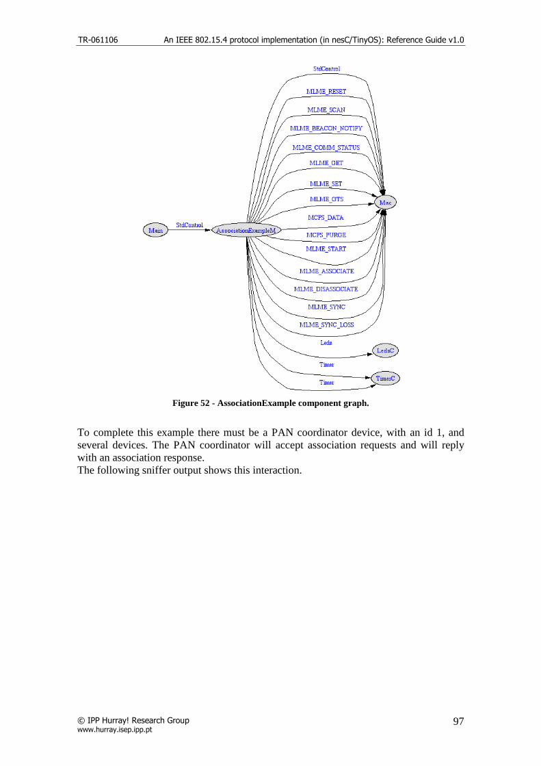
TR-061106 An IEEE 802.15.4 protocol implementation (in nesC/TinyOS): Reference Guide v1.0
© IPP Hurray! Research Group www.hurray.isep.ipp.pt
97
Figure 52 - AssociationExample component graph.
To complete this example there must be a PAN coordinator device, with an id 1, and several devices. The PAN coordinator will accept association requests and will reply with an association response. The following sniffer output shows this interaction.

TR-061106 An IEEE 802.15.4 protocol implementation (in nesC/TinyOS): Reference Guide v1.0
© IPP Hurray! Research Group www.hurray.isep.ipp.pt
98
Figure 53 - AssociationExample sniffer output.
4.2. GTSManagementExample application This simple application demonstrates the usage of the GTS allocation request. The device already has a manually assigned short address and tries to request a transmit GTS allocation. After the allocation is successfully acknowledge and the PAN coordinator updates the GTS descriptors list in the beacon, the device will start to send

TR-061106 An IEEE 802.15.4 protocol implementation (in nesC/TinyOS): Reference Guide v1.0
© IPP Hurray! Research Group www.hurray.isep.ipp.pt
99
data messages to the coordinator. After 10 superframe counts the device will cease to transmit data and send a GTS deallocation request. If the device with the short address 0x0002 requests a receive GTS allocation the coordinator will start to send data frames to that device. This application is linked directly to the MAC layer. The next figure illustrates the component wiring to the Mac component.
Figure 54 - GTSManagementExample component graph.
To complete this example there must be a PAN coordinator device, with an id 1, and several devices. The PAN coordinator will accept GTS requests up to 7. The devices will try to allocate a GTS time slot to send data. The allocation will last for 10 superframe periods after which the device will deallocate the time slot. During the period of the allocation the device will light the green led. The following sniffer output shows this interaction.

TR-061106 An IEEE 802.15.4 protocol implementation (in nesC/TinyOS): Reference Guide v1.0
© IPP Hurray! Research Group www.hurray.isep.ipp.pt
100
…
…

TR-061106 An IEEE 802.15.4 protocol implementation (in nesC/TinyOS): Reference Guide v1.0
© IPP Hurray! Research Group www.hurray.isep.ipp.pt
101
Figure 55 - GTSManagementExample sniffer output.
4.3. DataSendExample application These simple applications demonstrate the different forms to send a data packet
with several types of transmission options combinations. In this application the devices already have a short address meaning they are associated with the PAN coordinator. When the application starts the short address and the PANId is assigned to the device and a repeat timer starts. On each execution of the timer there are two different operation modes depending if the device is the coordinator or not. The application starts to send a message by issuing the MCPS_DATA.request primitive. The transmit options or TxOptions parameter, last argument of the primitive, define the transmission options for the data frame, allowing the frame to be send in the GTS or during the CAP period using the CSMA/CA or like an indirect transmission. The frame can also be send with an acknowledgment request. The function set_txoptions(ack, gts, indirect_transmission, security) is used to build the TxOptions 8 bit variable.
This application is linked directly to the MAC layer. The next figure illustrates the component wiring to the Mac component.

TR-061106 An IEEE 802.15.4 protocol implementation (in nesC/TinyOS): Reference Guide v1.0
© IPP Hurray! Research Group www.hurray.isep.ipp.pt
102
Figure 56 - DataSendExample component graph.
To complete this example there must be a PAN coordinator device, with an id 1, and up to three normal devices with an id from 2 to 4. The PAN coordinator will send data packets indirectly. The device descriptors will show in the pending addresses fields of the beacon. The normal devices will send periodic data packets and if their address is in the pending addresses descriptor of the beacon, they will request the data packet. Every time the primitive MCPS_DATA.request is issued by the MAC upper layer the green led will toggle and when a message is received the red led will toggle. The following sniffer output shows this interaction.

TR-061106 An IEEE 802.15.4 protocol implementation (in nesC/TinyOS): Reference Guide v1.0
© IPP Hurray! Research Group www.hurray.isep.ipp.pt
103
…
Figure 57 - DataSendExample sniffer output
4.4. SimpleRoutingExample application
This simple application demonstrates how to route data messages in a cluster tree topology. Each device sends data messages to the PAN coordinator with the first 2 bytes of the data payload as a routing field with the destination address of the desired device. When the PAN coordinator receives the data frame, it will read the payload and create a new data frame with the destination source address of the short address located

TR-061106 An IEEE 802.15.4 protocol implementation (in nesC/TinyOS): Reference Guide v1.0
© IPP Hurray! Research Group www.hurray.isep.ipp.pt
104
in the 2 bytes of the data payload. The coordinator will insert in the data payload the number of routed packets. The device already has a manually assigned short address. This application is linked directly to the MAC layer. The next figure illustrates the component wiring to the Mac component.
Figure 58 -SimpleRoutingExample component graph.
To complete this example there must be a PAN coordinator device, with an id 1, and two normal devices one with an id 2 and 3. If the device has an id of 2 it will try to send data messages to the coordinator, toggling the green led for each packet send. The coordinator will read the data payload and will send a packet to the mote id 3. This mote will toggle the red led for each packet received. The following sniffer output shows this interaction.

TR-061106 An IEEE 802.15.4 protocol implementation (in nesC/TinyOS): Reference Guide v1.0
© IPP Hurray! Research Group www.hurray.isep.ipp.pt
105
Figure 59 - SimpleRoutingExample sniffer output.

TR-061106 An IEEE 802.15.4 protocol implementation (in nesC/TinyOS): Reference Guide v1.0
© IPP Hurray! Research Group www.hurray.isep.ipp.pt
106
5. References [1] IEEE 802.15.4 Standard-2003, "Part 15.4: Wireless Medium Access Control (MAC) and Physical Layer (PHY) Specifications for Low-Rate Wireless Personal Area Networks (LR-WPANs)", IEEE-SA Standards Board, 2003. [2] D. Gay, P. Levis, R. Behren, M. Welsh, E. Brewer, D. Culler, “The nesC Language: A Holistic Approach to Networked Embedded Systems”, in PLDI’03. [3] www.tinyos.net [4] Crossbow Technologies INC. http://www.xbow.com [5] A. Koubaa , M. Alves, E. Tovar, “Lower Protocol Layers for Wireless Sensor Networks: A Survey”, IPP-HURRAY Technical Report, HURRAY-TR-051101, Nov 2005. [6] ATmega128L 8-bit AVR Microntroller Datasheet, Atmel ref: 2467MAVR- 11/04, http://www.atmel.com [7] Chipcon, SmartRF CC2420 Datasheet (rev 1.3), 2005. http://www.chipcon.com