TPIs M - ARDETEM SFERE · p3 1. INTRODUCTION • The TPIs M is an extra slim module (7.2mm)...
15
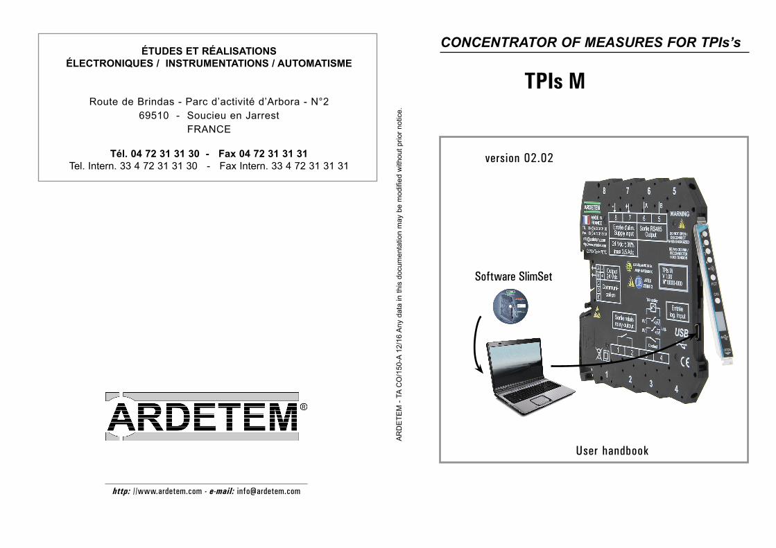
ARDETEM - TA CO/150-A 12/16 Any data in this documentation may be modified without prior notice. ÉTUDES ET RÉALISATIONS ÉLECTRONIQUES / INSTRUMENTATIONS / AUTOMATISME Route de Brindas - Parc d’activité d’Arbora - N°2 69510 - Soucieu en Jarrest FRANCE Tél. 04 72 31 31 30 - Fax 04 72 31 31 31 Tel. Intern. 33 4 72 31 31 30 - Fax Intern. 33 4 72 31 31 31 http: //www.ardetem.com - e-mail: [email protected] CONCENTRATOR OF MEASURES FOR TPIs’s TPIs M User handbook version 02.02 Software SlimSet
Transcript of TPIs M - ARDETEM SFERE · p3 1. INTRODUCTION • The TPIs M is an extra slim module (7.2mm)...
AR
DE
TEM
- TA
CO
/150
-A 1
2/16
Any
dat
a in
this
doc
umen
tatio
n m
ay b
e m
odifi
ed w
ithou
t prio
r not
ice.
ÉTUDES ET RÉALISATIONS ÉLECTRONIQUES / INSTRUMENTATIONS / AUTOMATISME
Route de Brindas - Parc d’activité d’Arbora - N°269510 - Soucieu en Jarrest
FRANCE
Tél. 04 72 31 31 30 - Fax 04 72 31 31 31Tel. Intern. 33 4 72 31 31 30 - Fax Intern. 33 4 72 31 31 31
http: //www.ardetem.com - e-mail: [email protected]
CONCENTRATOR OF MEASURES FOR TPIs’s
TPIs M
User handbook
version 02.02
Software SlimSet
p1
Summary
UE conformity declaration p2
1 . INTRODUCTION p3
1.1 General features p3
1.2 Communication interfaces p3
• Digital data link RS485 2 wire p3 • USB p4
1.3 Functions p4
• Interface for power supply distribution for TPIs p4 • Supervisor and concentrator of measures for TPIs p4 • 1 isolated logic input p4 • 1 alarm output of the type «potential free contact» p5
1.4 Available options p6
2 . DIMENSIONS - CONNECTIONS p6
3. CONFIGURATION OF A LOCAL NETWORK OF TPIs p8
4 . ANNEXE 1: MODBUS p9
5 . ANNEXE 2: CALCULATIONS (OPTION C) p14
p2
UE CONFORMITY DECLARATION
The manufacturer: ARDETEM-SFERE Route de Brindas Parc d’activité d’Arbora n°2 69510 Soucieu en Jarrest France
declares that the following product: Name: Measure concentrator Type: TPIs Mcomplies with the following directives and standards:
The EMC Directive 2014/30/UE EN 61326-1 : 2013
The Low Voltage Directive 2014/35/UE EN 61010-1 : 2011
The ATEX directive 2014/34/UE EN 60079-0 : 2011 EN 60079-15 : 2010
Soucieu en Jarrest, October 3, 2016
Jacques Huguet Signature of the Manager
This appliance has to be installed in an environment defined in pollution degree 2 / Overvoltage category II or better for a max. altitude of 2000 m.
Before any installation or maintenance work, make sure the power supply of the instrument is cut.
This symbole indicates that the module is protected by a double or reinforced isolation.
The person who has designed the system (electrical installation including the instrument) is sole responsable for the safety and must make sure it has been designed according to the current safety standards.
This appliance contains electronic components and should not be disposed of with the domestic waste.It should be collected with the WEEE (Waste Elec-trical and Electronic Equipment), according to the current regulation.
The instrument may be connected to dangerous electrical voltages.It must be mounted, connected and implemented respecting the current specific regulations, by a qualified technician, trai-ned to the safety regulations, who will have read this manual.
p3
1. INTRODUCTION
• The TPIs M is an extra slim module (7.2mm) designed for DIN rail mounting allowing to run a network of TPIs’s with:
• Distribution of the power supply (24Vdc ±30%)• Management of the inputs and outputs (the TPIs M is the network master)• Concentration and supervision of the measures via a digital output RS485 in MODBUS protocole.
• The programming is performed with a PC via the µUSB access and the software «SlimSet».
1.1 General features
Operating temperature ...................................-25°C to +70°C
Storage temperature ......................................-40°C to +85°C
Supply ............................................................16.8 to 31.2 Vdc
Max. power draw and internal dissipation ......0.6WMax. supply current of the Bus.......................3.5Adc
Galvanic partition....................2.5kV-50Hz-1mn between: - Supply, communication with the TPIs’s of the network. - Alarm relay output. - Logic input. - Digital data link (RS485). - µUSB.
Installation in ATEX / IECEx area 2
Installation: Pollution degree 2 / voltage surge II
Compliance with standards:
Low Voltage Directive 2014/35/UE...........EN 61010-1
ATEX 2014/34/UE ....................................EN 60079-0, EN 60079-15Directive EMC 2014/30/UE ......................EN 61326-1
Marking:
II 3 G Ex nA IIC T4 Gc
1.2 Communication interfaces
• Digital data link RS485 2 wire
Protocoles Modbus-JbusFormat of the data: integer and double integerExclusive transmission format: 1 start bit, 8 parityless data bits,1 stop bitSlave number between 1 and 255Baud rate between 1200 and 19200 BaudsOptional time delay before the response of 75ms.
Table of the Modbus addresses and the used functions: see annexe page 9
The digital data link is of the type «slave» in standard or «master» if option «M».In slave mode the MODBUS writing is possible with the option Y.
A set of 10 µswitches «SW201» on one side of the housing allows to select the end of line resistors (RT) and polarization resistors (RP) depending on the installation. (The end of line resistors allow to reduce the parasitic reflec-tions generated in a long line with high speed. They are not necessary if the environment is free from disturbances and the distance < 1000 m.)
MODE SW2011 2 3 4 5 6 7 8 9 10
Slave(RP = RT = 47kΩ
Master RP 47kΩ8.2kΩ630Ω
RT 47kΩ980Ω180Ω
Switch ON
p4
• USB
µUSB male footingVersion 2.0Programming software: SlimSet
1.3 Functions
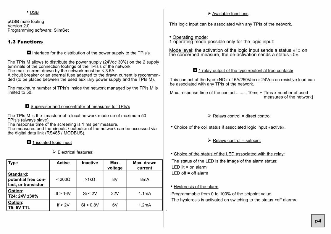
¦ Interface for the distribution of the power supply to the TPIs’s
The TPIs M allows to distribute the power supply (24Vdc 30%) on the 2 supply terminals of the connection footings of the TPIs’s of the network.The max. current drawn by the network must be < 3.5A.A circuit breaker or an exernal fuse adapted to the drawn current is recommen-ded (to be placed between the used auxiliary power supply and the TPIs M).
The maximum number of TPIs’s inside the network managed by the TPIs M is limited to 50.
¦ Supervisor and concentrator of measures for TPIs’s
The TPIs M is the «master» of a local network made up of maximum 50 TPIs’s (always slave).The response time of the screening is 1 ms per measure.The measures and the «inputs / outputs» of the network can be accessed via the digital data link (RS485 / MODBUS).
¦ 1 isolated logic input
Ø Available functions:
This logic input can be associated with any TPIs of the network.
Type Active Inactive Max.voltage
Max. drawn current
Standard:potential free con-tact, or transistor
< 200Ω >1kΩ 8V 8mA
Option:T24: 24V ±30% If > 16V Si < 2V 32V 1.1mA
Option:T5: 5V TTL If > 2V Si < 0,8V 6V 1.2mA
Ø Electrical features:
• Operating mode:1 operating mode possible only for the logic input:
Mode level: the activation of the logic input sends a status «1» on the concerned measure, the de-activation sends a status «0».
¦ 1 relay output of the type «potential free contact»
This contact of the type «NO» of 6A/250Vac or 24Vdc on resistive load can be associated with any TPIs of the network.
Max. response time of the contact ......... 10ms + [1ms x number of used measures of the network]
Ø Relays control = direct control
• Choice of the coil status if associated logic input «active».
Ø Relays control = setpoint
• Choice of the status of the LED associated with the relay:The status of the LED is the image of the alarm status:LED lit = on alarmLED off = off alarm
• Hysteresis of the alarm:Programmable from 0 to 100% of the setpoint value.The hysteresis is activated on switching to the status «off alarm».
p5
• Mode setpoint:1 setpoint configurable over the whole input range
• Mode window:2 setpoints configurable over the whole input range
• Type of safety:
HIGH:The coil of the relay is powered if:measure > setpoint (in mode setpoint)measure < setpoint 1 or measure > setpoint 2 (in mode window)
LOW:The coil of the relay is powered if:measure < setpoint (in mode setpoint)setpoint 1 < measure < setpoint 2 (in mode window)
• Time delay on the alarm:The relay time delay can be set from 0 to 25 seconds, in 0.1s. increments.It is active both on switching and switching off.
• Recording of the alarm:Allows to record the alarm after a setpoint has been passed. When the measure reverts below the alarm setpoint, the relay remains ON and the LED blinks to warn the user that the setpoint has been passed (reset to 0 by programming).
• Weight and width of the pulse programmable if piloted by an integrating converter TPIs 61 or TPIs 261.
• Self-diagnosis
• Sensor break
1.4 Available options
Option Reference of the TPIsMODBUS writing (in mode slave) TPIs M Y
Master TPIs M MOption calculations (C) TPIs M C
logic input 24V 30% TPIs M T24logic input 5V TTL TPIs M T5
2. DIMENSIONS - CONNECTIONS
.........................Dimensions: 7.2 x 114 x 114 mmHousing: ..........self-extinguishing case of PBTTerminals: ........removable screw terminal block for screwed connections (2.5 mm² flexible or rigid)
Screw thread M3Max. tightening torque: 0.5Nm / 4.5in.lbsMin. solid/stranded conductor section: 0.2mm2 / 26A WGMax. solid/stranded conductor section: 2.5mm2 / 14A WG
Protection: ...................................... case / terminals: IP20
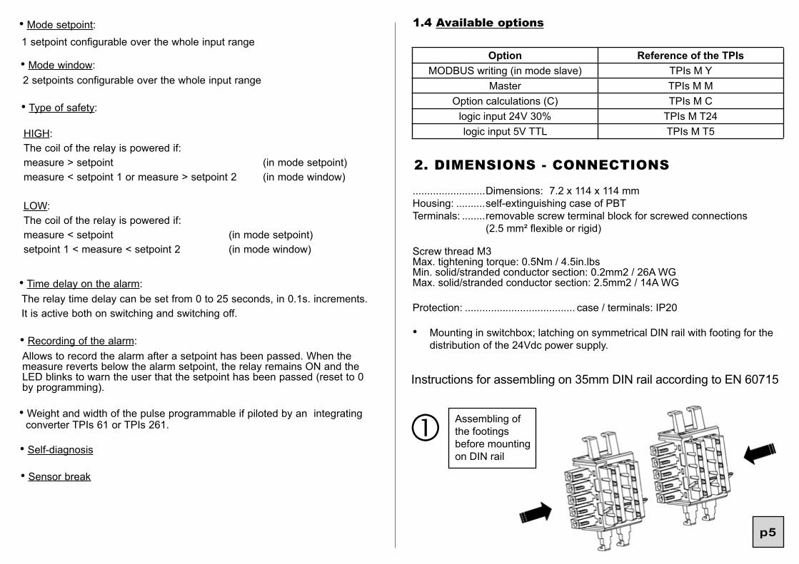
• Mounting in switchbox; latching on symmetrical DIN rail with footing for the distribution of the 24Vdc power supply.
Instructions for assembling on 35mm DIN rail according to EN 60715
Assembling of the footings before mounting on DIN rail
p5

p6
Assembling of the footings on the rail
BEWARE:The polarization tongue is at the bottom.
Mounting Unmounting
The TPIs must be mounted one after another.
• INSTALLATION IN AREA 2 (ATEX)
II3G Ex nA nC IIC T4 Gc
The product must be installed by qualified staff, competent on the directives and the regulation applicable to the area 2.
It must be installed in a protecting enveloppe conform with the EN 60079-15.
The operator must ensure an external protection in order to prevent transient disturbances on the supply of the modules higher than 40% of the nominal voltage.
The USB cable must be inserted or withdrawn only if the instrument has been set off tension or if the area is safe.The converter must be disconnected from its DIN rail footing only if the rail supply has been set off tension or if the area is safe.
The installation must be done according to the EN 60079-14 : 2014.
12
3
4
2
1
p7
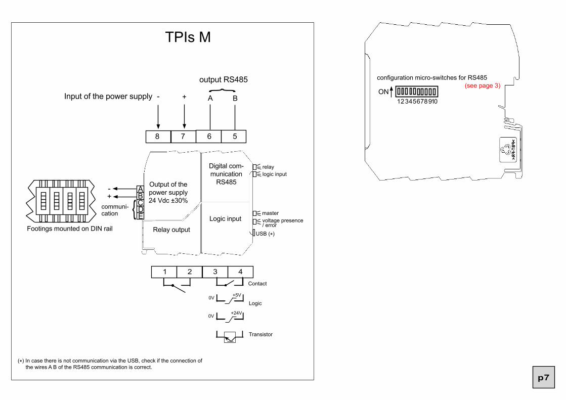
+24V
+5V
TPIs M
8 7 6 5
1 2 3 4
relaylogic input
mastervoltage presence / error
USB (*)
Contact
Logic0V
0V
configuration micro-switches for RS485
ON12345678910+- A B
Digital com-munication
RS485
Logic inputRelay output
Input of the power supply
ABCD
+-
communi-cation
Footings mounted on DIN rail
Output of the power supply 24 Vdc ±30%
E
Transistor
(see page 3)
(*) In case there is not communication via the USB, check if the connection of the wires A B of the RS485 communication is correct.
output RS485
p8
3. CONFIGURATION OF A LOCAL NETWORK OF TPIs’s
First start by launching the configuration software SlimSet.The purpose is to define your network using the software.
1) First connect the TPIs M to the PC.
Click on «communication with the devices» and then on «add the connected device to the architecture». Then give its position in the architecture.Now click on «communication through the master» and then «add or remove some devices».
The software will then take up all the instruments present on the bus and read their configuration one by one.
For each instrument detected, the SlimSet will request its position on the ar-chitecture. This position can be determined by a specific blinking of the green led of the concerned instrument (morse code blinking: twice on, once off). This position will be saved inside the TPIs M configuration and restored at each configuration reading.
3) Then programme each of the instruments, as well as the links between ins-truments:for each of the outputs of the output modules (TPIs 4R, TPIs 2A/4A ...) you must define the converter associated with this output, as well as the measure associated with this output.
4) Then programme on the TPIs M the measures to be braught back(collected measures).
The network must always be validated after adding / removing an instrument and after the modification of all the links between instruments.
5) Then connect yourself on the TPIs M and click on «communication with the devices» and on «communication through the master» and then on «send the configuration to all devices».
6) Then connect yourself on the TPIs M and click on «validate network».This will record the configuration of the bus in order to point out any error (loss of a module for example).
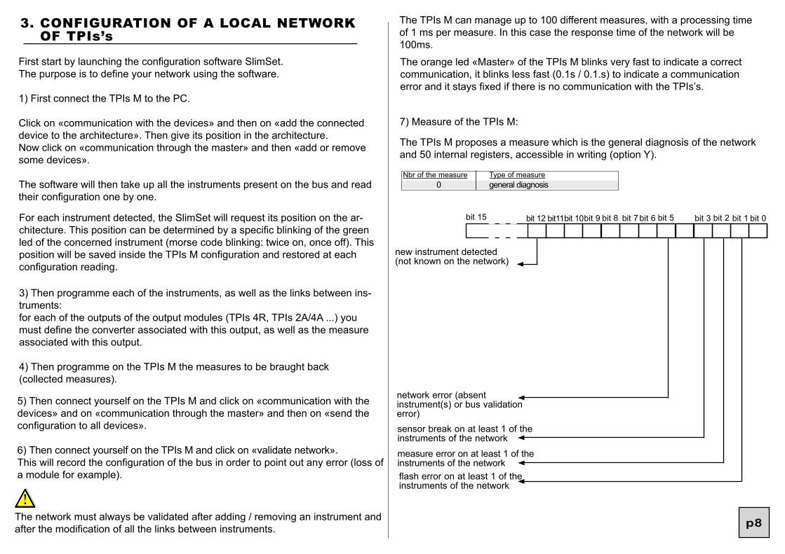
The TPIs M can manage up to 100 different measures, with a processing time of 1 ms per measure. In this case the response time of the network will be 100ms.
7) Measure of the TPIs M:
The TPIs M proposes a measure which is the general diagnosis of the network and 50 internal registers, accessible in writing (option Y).
Nbr of the measure0
Type of measuregeneral diagnosis
bit 15 bit 5 bit 1bit 2bit 3 bit 0bit 6bit 7bit 8
new instrument detected (not known on the network)
The orange led «Master» of the TPIs M blinks very fast to indicate a correct communication, it blinks less fast (0.1s / 0.1.s) to indicate a communication error and it stays fixed if there is no communication with the TPIs’s.
bit 9bit 10bit11bit 12
network error (absent instrument(s) or bus validation error)sensor break on at least 1 of the instruments of the network
measure error on at least 1 of the instruments of the networkflash error on at least 1 of the instruments of the network
p9
Word address250002500225004250062500825010250122501425016
...
...25198
Description (2 words)Measure to be brought back n°0Measure to be brought back n°1Measure to be brought back n°2Measure to be brought back n°3Measure to be brought back n°4Measure to be brought back n°5Measure to be brought back n°6Measure to be brought back n°7Measure to be brought back n°8......Measure to be brought back n°99
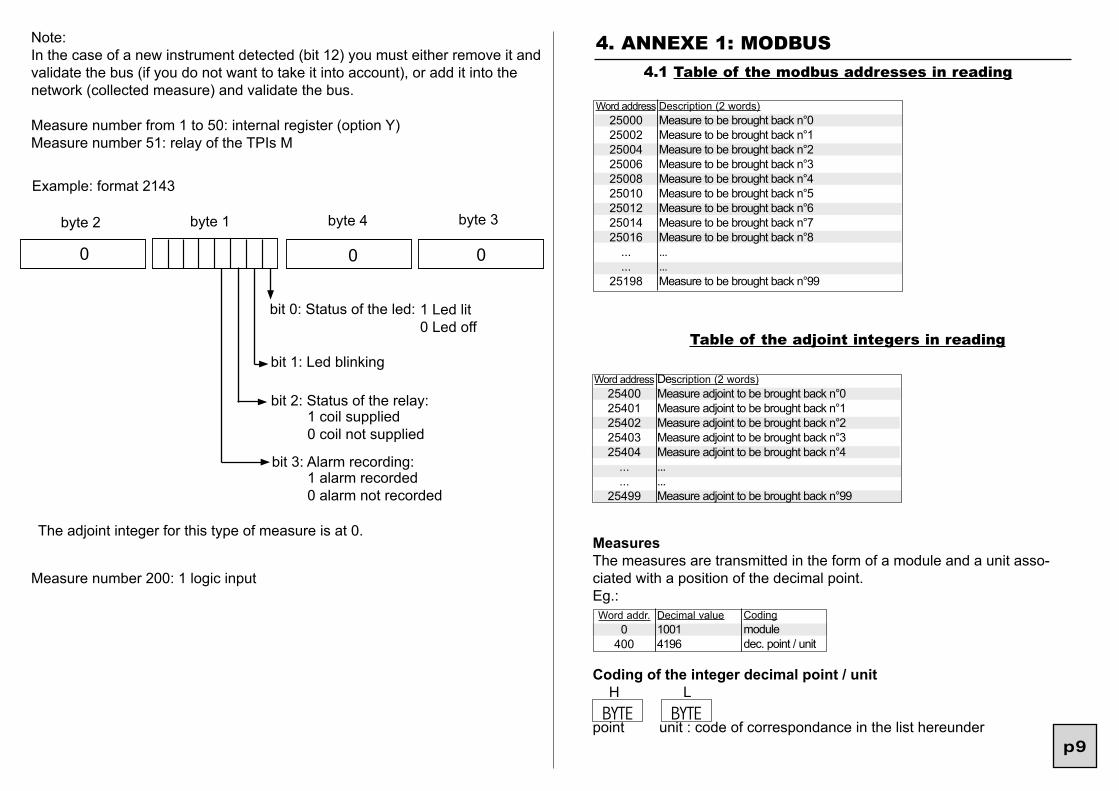
4. ANNEXE 1: MODBUS 4.1 Table of the modbus addresses in reading
Word address2540025401254022540325404
...
...25499
Description (2 words)Measure adjoint to be brought back n°0Measure adjoint to be brought back n°1Measure adjoint to be brought back n°2Measure adjoint to be brought back n°3Measure adjoint to be brought back n°4......Measure adjoint to be brought back n°99
Table of the adjoint integers in reading
Note:In the case of a new instrument detected (bit 12) you must either remove it and validate the bus (if you do not want to take it into account), or add it into the network (collected measure) and validate the bus.
Measure number from 1 to 50: internal register (option Y)Measure number 51: relay of the TPIs M
Example: format 2143
byte 1byte 2 byte 4 byte 3
0 0 0
bit 0: Status of the led: 1 Led lit0 Led off
bit 1: Led blinking
bit 2: Status of the relay:1 coil supplied0 coil not supplied
bit 3: Alarm recording:1 alarm recorded0 alarm not recorded
The adjoint integer for this type of measure is at 0.MeasuresThe measures are transmitted in the form of a module and a unit asso-ciated with a position of the decimal point.Eg.: Word addr.
0400
Decimal value10014196
Codingmoduledec. point / unit
Coding of the integer decimal point / unit H L
point unit : code of correspondance in the list hereunder BYTE BYTE
Measure number 200: 1 logic input
p10
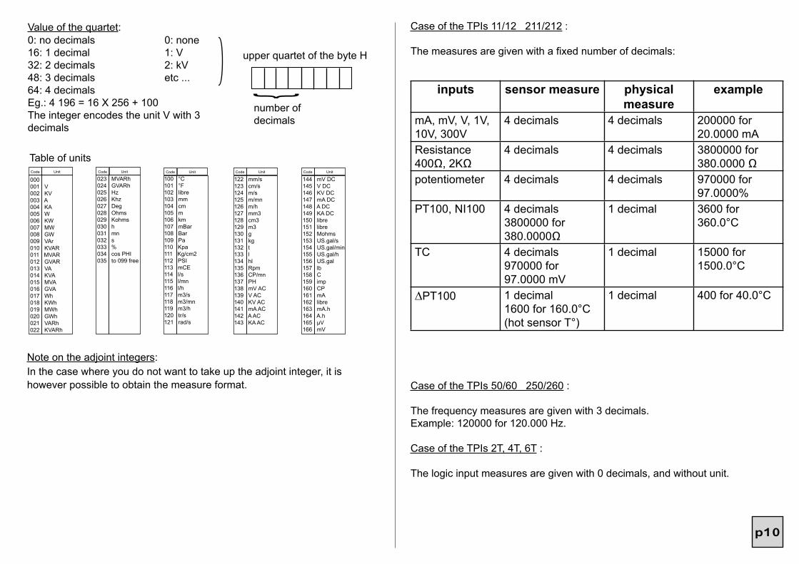
Table of unitsCode Unit Code Unit Code Unit Code Unit Code Unit
000 001 V 002 KV 003 A 004 KA005 W 006 KW 007 MW 008 GW 009 VAr010 KVAR 011 MVAR 012 GVAR 013 VA 014 KVA015 MVA 016 GVA 017 Wh 018 KWh 019 MWh020 GWh 021 VARh 022 KVARh
023 MVARh024 GVARh025 Hz 026 Khz 027 Deg 028 Ohms 029 Kohms030 h 031 mn 032 s 033 % 034 cos PHI035 to 099 free
100 °C 101 °F 102 libre 103 mm 104 cm105 m 106 km 107 mBar 108 Bar 109 Pa110 Kpa 111 Kg/cm2112 PSI 113 mCE 114 l/s115 l/mn 116 l/h 117 m3/s 118 m3/mn119 m3/h120 tr/s 121 rad/s
122 mm/s 123 cm/s 124 m/s125 m/mn 126 m/h 127 mm3 128 cm3 129 m3 130 g 131 kg 132 t 133 l 134 hl135 Rpm 136 CP/mn137 PH 138 mV AC139 V AC140 KV AC141 mA AC142 A AC 143 KA AC
144 mV DC145 V DC 146 KV DC147 mA DC148 A DC 149 KA DC150 libre 151 libre152 Mohms153 US.gal/s154 US.gal/min155 US.gal/h156 US.gal157 lb 158 C 159 imp160 CP 161 mA 162 libre 163 mA.h 164 A.h165 µV 166 mV
0: no decimals 0: none16: 1 decimal 1: V32: 2 decimals 2: kV48: 3 decimals etc ...64: 4 decimalsEg.: 4 196 = 16 X 256 + 100The integer encodes the unit V with 3 decimals
upper quartet of the byte H
number of decimals
Value of the quartet:
Note on the adjoint integers:In the case where you do not want to take up the adjoint integer, it is however possible to obtain the measure format.
inputs sensor measure physical measure
example
mA, mV, V, 1V, 10V, 300V
4 decimals 4 decimals 200000 for 20.0000 mA
Resistance 400Ω, 2KΩ
4 decimals 4 decimals 3800000 for 380.0000 Ω
potentiometer 4 decimals 4 decimals 970000 for 97.0000%
PT100, NI100 4 decimals3800000 for 380.0000Ω
1 decimal 3600 for 360.0°C
TC 4 decimals970000 for 97.0000 mV
1 decimal 15000 for 1500.0°C
∆PT100 1 decimal1600 for 160.0°C(hot sensor T°)
1 decimal 400 for 40.0°C
Case of the TPIs 11/12 211/212 :
The measures are given with a fixed number of decimals:
Case of the TPIs 50/60 250/260 :
The frequency measures are given with 3 decimals.Example: 120000 for 120.000 Hz.
Case of the TPIs 2T, 4T, 6T :
The logic input measures are given with 0 decimals, and without unit.
p11
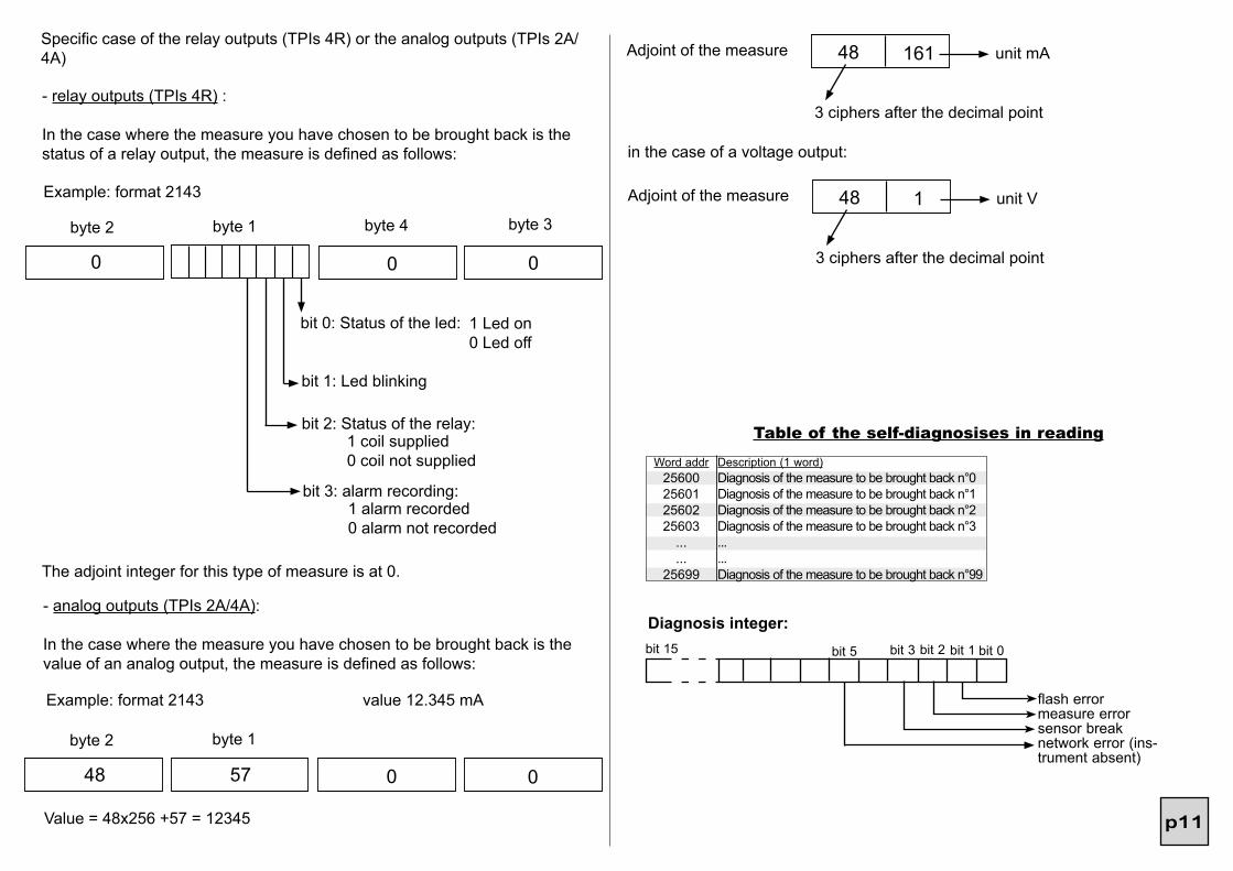
Specific case of the relay outputs (TPIs 4R) or the analog outputs (TPIs 2A/4A)
- relay outputs (TPIs 4R) :
In the case where the measure you have chosen to be brought back is the status of a relay output, the measure is defined as follows:
Example: format 2143
The adjoint integer for this type of measure is at 0.
- analog outputs (TPIs 2A/4A):
In the case where the measure you have chosen to be brought back is the value of an analog output, the measure is defined as follows:
Example: format 2143 value 12.345 mA
byte 1byte 2
48 0 057
Value = 48x256 +57 = 12345
Adjoint of the measure 48 161 unit mA
3 ciphers after the decimal point
in the case of a voltage output:
Adjoint of the measure 48 1 unit V
3 ciphers after the decimal point
bit 15 bit 3 bit 0
flash errormeasure errorsensor breaknetwork error (ins-trument absent)
Diagnosis integer:bit 1bit 2
Word addr25600256012560225603
...
...25699
Description (1 word)Diagnosis of the measure to be brought back n°0Diagnosis of the measure to be brought back n°1Diagnosis of the measure to be brought back n°2Diagnosis of the measure to be brought back n°3......Diagnosis of the measure to be brought back n°99
Table of the self-diagnosises in reading
bit 5
byte 1byte 2 byte 4 byte 3
0 0 0
bit 0: Status of the led: 1 Led on0 Led off
bit 1: Led blinking
bit 2: Status of the relay:1 coil supplied0 coil not supplied
bit 3: alarm recording:1 alarm recorded0 alarm not recorded
p12
Word addr.012345......
294295296297298299
Description
External register 1
Adjoint integer of the register 1 (see page 9)
External register 2
Adjoint integer of the register 2......
External register 99
Adjoint integer of the register 99
External register 100
Adjoint integer of the register 100
Table of the Modbus addresses in writing
External register 1 to 100: 2 words in the programmed format
Example:
You wish to command a relay on an external measure of temperature:Choose for this relay a register, for example register 1.To send the temperature refer to page 9 (note on the adjoint integers):
Measure with 1 decimal 1200 for 120.0°
adjoint integer 1 0 100 °C
unit in the table (see page 9)
1 decimal
Hence the words to be written are the following:
format 2143
register 1 4 176 0 0
byte 2 byte 1 byte 4 byte 3
(only with the option Y)
4.2 Description of the born Modbus functions: Reading of N words: Function n°3
Register 1 adjoint 16 100
byte 2 byte 1
this means 6 bytes must be written to the address 3:
4, 176, 0, 0, 16, 100 (for a format 2143)
Slave number
1 byte 1 byte
Function3 or 4
2 bytes
CRC 161st word
MSB
address
LSB
Nbr of
MSB
words
LSB2 bytes 2 bytes
Slave number
1 byte 1 byte 1 byte
Function3 or 4
Number of read bytes
Response sequence:1st word
MSB
value
LSB2 bytes
2nd word
MSB
value
LSB2 bytes
Request sequence:
2 bytes
CRC 16
2 bytes
CRC 16
Slave number
1 byte 1 byte
Function16
1st word address
Numbr of words to be enfor.
Writing of N words: Function N°16:
Request sequence:
Value of the words to be enforced
2 bytes 2 bytes
Numbr of words to be enfor.
2 bytes
Numbr of bytes to be enfor.
1 byte n bytes
Slave number
1 byte 1 byte 1 byte
Function16
1st word address
Response sequence:
2 bytes
CRC 16
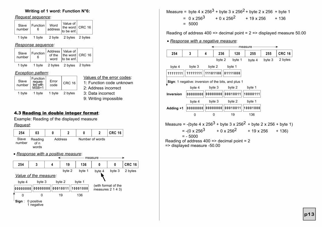
p13
11111111
byte 4
11111111
byte 3
111 0 11 0 0
byte 2
0 1111 0 0 0
byte 1
Sign: 1 negative: inversion of the bits, and plus 1
Measure = byte 4 x 2563 + byte 3 x 2562 + byte 2 x 256 + byte 1 = 0 x 2563 + 0 x 2562 + 19 x 256 + 136 = 5000
Reading of address 400 => decimal point = 2 => displayed measure 50.00
254 3 4 236
• Response with a negative measure:
120 255 CRC 16255
measure
byte 2 byte 1 byte 4 byte 3 2 bytes
0 0 0 0 0 0 0 0
byte 4
0 0 0 0 0 0 0 0
byte 3
0 0 0 1 0 0 11
byte 2
1 0 0 0 0 111
byte 1
0 0 0 0 0 0 0 0
byte 4
0 0 0 0 0 0 0 0
byte 3
0 0 0 1 0 0 11
byte 2
1 0 0 0 1 0 0 0
byte 1
0 0 19 136
Adding +1
Inversion
Measure = -(byte 4 x 2563 + byte 3 x 2562 + byte 2 x 256 + byte 1) = -(0 x 2563 + 0 x 2562 + 19 x 256 + 136) = - 5000Reading of address 400 => decimal point = 2 => displayed measure -50.00
2 bytes
CRC 16
Slave number
1 byte 1 byte
Function6
2 bytes
CRC 16Word address
Writing of 1 word: Function N°6:Request sequence:
2 byte
Value of the word to be enf.
2 bytes
Value of the word to be enf.
2 bytes
Slave number
1 byte 1 byte 2 bytes
Function6
Address of the word
2 bytes
CRC 16Slave number
1 byte 1 byte 1 byte
Functionreques-ted with MSB=1
Error code
Response sequence:
Exception pattern:Values of the error codes:1: Function code unknown2: Address incorrect3: Data incorrect9: Writing impossible
0 0 0 0 0 0 0 0
byte 4
0 0 0 0 0 0 0 0
byte 3
0 0 0 1 0 0 11
byte 2
1 0 0 0 1 0 0 0
byte 1
0
Sign : 0 positive 1 negative
0 19 136
Value of the measure:
254 3 4 19
• Response with a positive measure:
136 0 CRC 160
measure
byte 2 byte 1 byte 4 byte 3 2 bytes
254 03 0 2
4.3 Reading in double integer format:Example: Reading of the displayed measureRequest:
0AddressReading
of n words
Slave number
Number of words
2 CRC 16
(with format of the measures 2 1 4 3)
p14
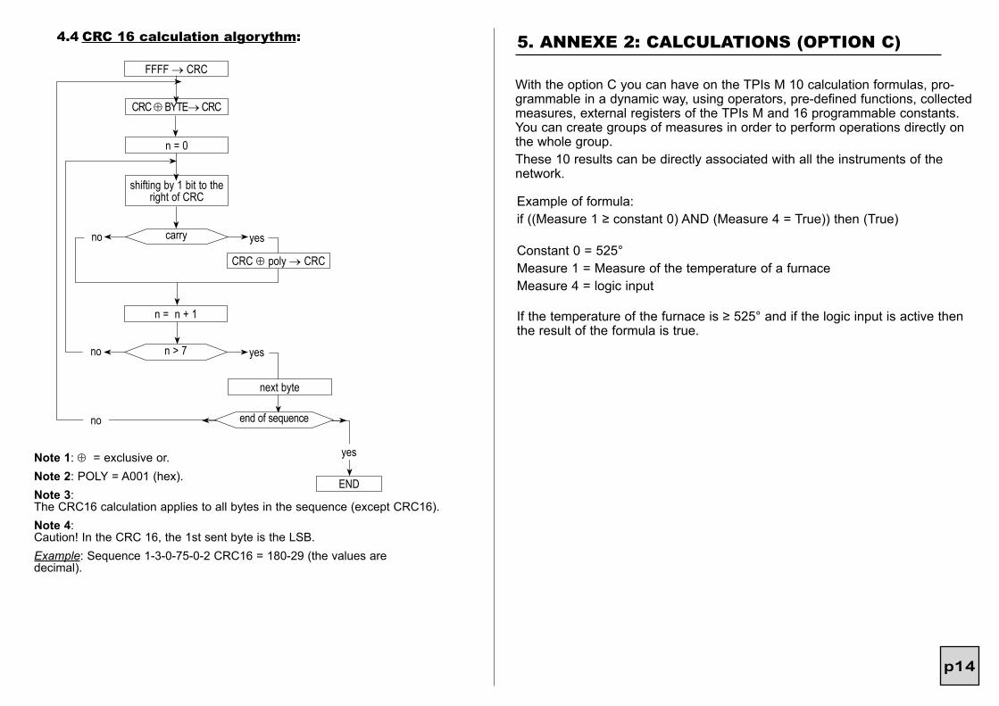
4.4 CRC 16 calculation algorythm:
Note 1: ⊕ = exclusive or.Note 2: POLY = A001 (hex).Note 3: The CRC16 calculation applies to all bytes in the sequence (except CRC16).Note 4: Caution! In the CRC 16, the 1st sent byte is the LSB.Example: Sequence 1-3-0-75-0-2 CRC16 = 180-29 (the values are decimal).
FFFF → CRC
CRC ⊕ BYTE→ CRC
yesno
n = 0
n = n + 1
yesno
shifting by 1 bit to the right of CRC
carry
CRC ⊕ poly → CRC
n > 7
next byte
no
END
yes
end of sequence
5. ANNEXE 2: CALCULATIONS (OPTION C)
With the option C you can have on the TPIs M 10 calculation formulas, pro-grammable in a dynamic way, using operators, pre-defined functions, collected measures, external registers of the TPIs M and 16 programmable constants. You can create groups of measures in order to perform operations directly on the whole group.These 10 results can be directly associated with all the instruments of the network.
Example of formula:if ((Measure 1 ≥ constant 0) AND (Measure 4 = True)) then (True)
Constant 0 = 525°Measure 1 = Measure of the temperature of a furnaceMeasure 4 = logic input
If the temperature of the furnace is ≥ 525° and if the logic input is active then the result of the formula is true.


![THERMOPLASTIC POLYIMIDE NEW-TPI®These NEW-TPI® polymers are more readily recrystallizable than the LaRC-TPIs [12, 13]. The recrystallization behavior for Samples of MTC-LV subjected](https://static.fdocuments.net/doc/165x107/5f1839cbd13a6578e665c11d/thermoplastic-polyimide-new-tpi-these-new-tpi-polymers-are-more-readily-recrystallizable.jpg)