MOTORES DE INDUÇÃO TRIFÁSICOS Eletrônica Industrial II Danila 00028-3 Juliana01035-3.
Upload
rahul-koulCategory
view
473download
3description

TimeProvider 5000IEEE 1588 Grand Master Clock / NTP Server
User’s GuideRevision G – July 2012
Part Number 098-00028-000

Symmetricom, Inc.2300 Orchard Parkway
San Jose, CA 95131-1017
U.S.A.
http://www.symmetricom.com
Copyright © 2012 Symmetricom, Inc.
All rights reserved. Printed in U.S.A.
All product names, service marks, trademarks, and registered trademarks
used in this document are the property of their respective owners.

Contents
How to Use This Guide
Purpose of This Guide . . . . . . . . . . . . . . . . . . . . . . . . . . . . . . . . . . . . . . . . . . .22
Who Should Read This Guide. . . . . . . . . . . . . . . . . . . . . . . . . . . . . . . . . . . . . .22
Structure of This Guide . . . . . . . . . . . . . . . . . . . . . . . . . . . . . . . . . . . . . . . . . . .23
Conventions Used in This Guide. . . . . . . . . . . . . . . . . . . . . . . . . . . . . . . . . . . .24
Warnings, Cautions, Recommendations, and Notes . . . . . . . . . . . . . . . . . . . .25
Related Documents and Information. . . . . . . . . . . . . . . . . . . . . . . . . . . . . . . . .26
Where to Find Answers to Product and Document Questions . . . . . . . . . . . . .26
What’s New In This Guide. . . . . . . . . . . . . . . . . . . . . . . . . . . . . . . . . . . . . . . . .26
Chapter 1 Overview
Overview . . . . . . . . . . . . . . . . . . . . . . . . . . . . . . . . . . . . . . . . . . . . . . . . . . . . . .30TimeProvider 5000 Features . . . . . . . . . . . . . . . . . . . . . . . . . . . . . . . . . .30Software Options . . . . . . . . . . . . . . . . . . . . . . . . . . . . . . . . . . . . . . . . . . .31Security Features . . . . . . . . . . . . . . . . . . . . . . . . . . . . . . . . . . . . . . . . . . .32
TimeProvider 5000 Connections. . . . . . . . . . . . . . . . . . . . . . . . . . . . . . . . . . . .33UTI Input and Output Connections . . . . . . . . . . . . . . . . . . . . . . . . . . . . . .34Communications Connections . . . . . . . . . . . . . . . . . . . . . . . . . . . . . . . . .35Output Connections . . . . . . . . . . . . . . . . . . . . . . . . . . . . . . . . . . . . . . . . .37Input Connections . . . . . . . . . . . . . . . . . . . . . . . . . . . . . . . . . . . . . . . . . . .40Power and Ground Connections. . . . . . . . . . . . . . . . . . . . . . . . . . . . . . . .42
Physical Description . . . . . . . . . . . . . . . . . . . . . . . . . . . . . . . . . . . . . . . . . . . . .43
Functional Description. . . . . . . . . . . . . . . . . . . . . . . . . . . . . . . . . . . . . . . . . . . .45TimeProvider 5000 Expansion Shelf System . . . . . . . . . . . . . . . . . . . . . .45IMC Module LEDs. . . . . . . . . . . . . . . . . . . . . . . . . . . . . . . . . . . . . . . . . . .51IOC Module LEDs . . . . . . . . . . . . . . . . . . . . . . . . . . . . . . . . . . . . . . . . . . .51Expansion Shelf LEDs . . . . . . . . . . . . . . . . . . . . . . . . . . . . . . . . . . . . . . .51Communication Ports . . . . . . . . . . . . . . . . . . . . . . . . . . . . . . . . . . . . . . . .52Synchronization and Timing Inputs. . . . . . . . . . . . . . . . . . . . . . . . . . . . . .52Synchronization and Timing Outputs . . . . . . . . . . . . . . . . . . . . . . . . . . . .52System Inputs and Outputs. . . . . . . . . . . . . . . . . . . . . . . . . . . . . . . . . . . .53TP E10 Expansion Shelf System Outputs . . . . . . . . . . . . . . . . . . . . . . . .54TP E30 Expansion Shelf System Outputs . . . . . . . . . . . . . . . . . . . . . . . .54Expansion Shelf ID Switch . . . . . . . . . . . . . . . . . . . . . . . . . . . . . . . . . . . .54
Configuration Management. . . . . . . . . . . . . . . . . . . . . . . . . . . . . . . . . . . . . . . .55
098-00028-000 Revision G – July, 2012 TimeProvider 5000 User’s Guide 3

Table of Contents
Alarms. . . . . . . . . . . . . . . . . . . . . . . . . . . . . . . . . . . . . . . . . . . . . . . . . . . . . . . .55
Chapter 2 Installing
Getting Started . . . . . . . . . . . . . . . . . . . . . . . . . . . . . . . . . . . . . . . . . . . . . . . . .58Security Considerations for TP5000 Installation . . . . . . . . . . . . . . . . . . . .58Site Survey . . . . . . . . . . . . . . . . . . . . . . . . . . . . . . . . . . . . . . . . . . . . . . . .58Installation Tools and Equipment . . . . . . . . . . . . . . . . . . . . . . . . . . . . . . .59
Unpacking the Unit . . . . . . . . . . . . . . . . . . . . . . . . . . . . . . . . . . . . . . . . . . . . . .60
Rack Mounting the Chassis . . . . . . . . . . . . . . . . . . . . . . . . . . . . . . . . . . . . . . .62Rack Mounting the TimeProvider 5000 Main Shelf. . . . . . . . . . . . . . . . . .62Rack Mounting the TP E10 & TP E30 Expansion Shelves . . . . . . . . . . . .64
Working With Modules . . . . . . . . . . . . . . . . . . . . . . . . . . . . . . . . . . . . . . . . . . .67Handling Modules . . . . . . . . . . . . . . . . . . . . . . . . . . . . . . . . . . . . . . . . . . .67Inserting Modules . . . . . . . . . . . . . . . . . . . . . . . . . . . . . . . . . . . . . . . . . . .68Removing Modules . . . . . . . . . . . . . . . . . . . . . . . . . . . . . . . . . . . . . . . . . .68
Signal Connections . . . . . . . . . . . . . . . . . . . . . . . . . . . . . . . . . . . . . . . . . . . . . .68Communications Connections . . . . . . . . . . . . . . . . . . . . . . . . . . . . . . . . .69TP 5000 Synchronization and Timing Connections . . . . . . . . . . . . . . . . .71TimeProvider E10 Synchronization and Timing Connections. . . . . . . . . .81TimeProvider E30 Synchronization and Timing Connections. . . . . . . . . .82
Connecting the GPS/GNSS Antenna . . . . . . . . . . . . . . . . . . . . . . . . . . . . . . . .83
Setting Shelf ID on Expansion Shelves. . . . . . . . . . . . . . . . . . . . . . . . . . . . . . .84
Making Ground and Power Connections . . . . . . . . . . . . . . . . . . . . . . . . . . . . .84Ground Connections . . . . . . . . . . . . . . . . . . . . . . . . . . . . . . . . . . . . . . . . .85Power Connections. . . . . . . . . . . . . . . . . . . . . . . . . . . . . . . . . . . . . . . . . .86Testing Power Connections . . . . . . . . . . . . . . . . . . . . . . . . . . . . . . . . . . .88
Installation Check List . . . . . . . . . . . . . . . . . . . . . . . . . . . . . . . . . . . . . . . . . . . .89
Applying Power to the TimeProvider 5000 . . . . . . . . . . . . . . . . . . . . . . . . . . . .89Normal Power Up Indications . . . . . . . . . . . . . . . . . . . . . . . . . . . . . . . . . .89
Chapter 3 CLI Commands and SNMP
CLI Overview. . . . . . . . . . . . . . . . . . . . . . . . . . . . . . . . . . . . . . . . . . . . . . . . . . .94TimeProvider 5000 CLI Command Conventions . . . . . . . . . . . . . . . . . . .95CLI Command Keyboard Usage . . . . . . . . . . . . . . . . . . . . . . . . . . . . . . . .95Command Line Format . . . . . . . . . . . . . . . . . . . . . . . . . . . . . . . . . . . . . . .96Command User Levels . . . . . . . . . . . . . . . . . . . . . . . . . . . . . . . . . . . . . . .97
4 TimeProvider 5000 User’s Guide 098-00028-000 Revision G – July, 2012

Table of Contents
TimeProvider 5000 CLI Command Set . . . . . . . . . . . . . . . . . . . . . . . . . . . . . . .97Command Syntax: . . . . . . . . . . . . . . . . . . . . . . . . . . . . . . . . . . . . . . . . .226Command Syntax: . . . . . . . . . . . . . . . . . . . . . . . . . . . . . . . . . . . . . . . . .227
Simple Network Management Protocol (SNMP) . . . . . . . . . . . . . . . . . . . . . . .266Management Information Base. . . . . . . . . . . . . . . . . . . . . . . . . . . . . . . .266Public MIBs . . . . . . . . . . . . . . . . . . . . . . . . . . . . . . . . . . . . . . . . . . . . . . .267Private MIBs . . . . . . . . . . . . . . . . . . . . . . . . . . . . . . . . . . . . . . . . . . . . . .268
Chapter 4 Provisioning
Establishing a Connection to the TimeProvider 5000 . . . . . . . . . . . . . . . . . . .272Communicating Through the Serial Port. . . . . . . . . . . . . . . . . . . . . . . . .272Communicating Through the Ethernet Port . . . . . . . . . . . . . . . . . . . . . .273
Managing the User Access List. . . . . . . . . . . . . . . . . . . . . . . . . . . . . . . . . . . .274Logging In . . . . . . . . . . . . . . . . . . . . . . . . . . . . . . . . . . . . . . . . . . . . . . . .275Adding a User . . . . . . . . . . . . . . . . . . . . . . . . . . . . . . . . . . . . . . . . . . . . .275Deleting A User. . . . . . . . . . . . . . . . . . . . . . . . . . . . . . . . . . . . . . . . . . . .276Displaying Current Users and User Access Levels . . . . . . . . . . . . . . . .276Changing a User’s Password . . . . . . . . . . . . . . . . . . . . . . . . . . . . . . . . .277Changing a User’s Access Level . . . . . . . . . . . . . . . . . . . . . . . . . . . . . .278
Provisioning for a RADIUS Server . . . . . . . . . . . . . . . . . . . . . . . . . . . . . . . . .279Provisioning the TP5000 for Remote Authentication . . . . . . . . . . . . . . .279Configuring a FreeRADIUS Server . . . . . . . . . . . . . . . . . . . . . . . . . . . . .279Configuring a Cisco ACS . . . . . . . . . . . . . . . . . . . . . . . . . . . . . . . . . . . .282
Provisioning the Ethernet Ports. . . . . . . . . . . . . . . . . . . . . . . . . . . . . . . . . . . .293Provisioning IMC Ethernet Port. . . . . . . . . . . . . . . . . . . . . . . . . . . . . . . .293Provisioning IOC Ethernet Ports . . . . . . . . . . . . . . . . . . . . . . . . . . . . . . .295
Provisioning VLAN . . . . . . . . . . . . . . . . . . . . . . . . . . . . . . . . . . . . . . . . . . . . .300
Provisioning PTP. . . . . . . . . . . . . . . . . . . . . . . . . . . . . . . . . . . . . . . . . . . . . . .304Packet Service Modes . . . . . . . . . . . . . . . . . . . . . . . . . . . . . . . . . . . . . .304PTP Profiles . . . . . . . . . . . . . . . . . . . . . . . . . . . . . . . . . . . . . . . . . . . . . .305PTP Parameters . . . . . . . . . . . . . . . . . . . . . . . . . . . . . . . . . . . . . . . . . . .308Management Addressing Mode . . . . . . . . . . . . . . . . . . . . . . . . . . . . . . .312Two-Step Clock Mode. . . . . . . . . . . . . . . . . . . . . . . . . . . . . . . . . . . . . . .313
Provisioning NTP . . . . . . . . . . . . . . . . . . . . . . . . . . . . . . . . . . . . . . . . . . . . . .321Provisioning an IOC Port as NTP Server . . . . . . . . . . . . . . . . . . . . . . . .322
098-00028-000 Revision G – July, 2012 TimeProvider 5000 User’s Guide 5

Table of Contents
Provisioning the Input Reference . . . . . . . . . . . . . . . . . . . . . . . . . . . . . . . . . .323Setting Reference Mode . . . . . . . . . . . . . . . . . . . . . . . . . . . . . . . . . . . . .323Setting Reference Criteria. . . . . . . . . . . . . . . . . . . . . . . . . . . . . . . . . . . .324Setting Input Priority Values . . . . . . . . . . . . . . . . . . . . . . . . . . . . . . . . . .325Setting GPS Port as Reference . . . . . . . . . . . . . . . . . . . . . . . . . . . . . . .326Setting GNSS Port as Reference . . . . . . . . . . . . . . . . . . . . . . . . . . . . . .328Setting a 1PPS+TOD Input as Reference. . . . . . . . . . . . . . . . . . . . . . . .329Setting an E1/T1 Input as Reference . . . . . . . . . . . . . . . . . . . . . . . . . . .330
Provisioning the Programmable E1/T1 Inputs. . . . . . . . . . . . . . . . . . . . . . . . .331Synchronization Status Message (SSM) . . . . . . . . . . . . . . . . . . . . . . . .332CRC State. . . . . . . . . . . . . . . . . . . . . . . . . . . . . . . . . . . . . . . . . . . . . . . .334Provisioning E1 Inputs . . . . . . . . . . . . . . . . . . . . . . . . . . . . . . . . . . . . . .334Provisioning T1 Inputs . . . . . . . . . . . . . . . . . . . . . . . . . . . . . . . . . . . . . .336
Provisioning the 1PPS+TOD Inputs . . . . . . . . . . . . . . . . . . . . . . . . . . . . . . . .339
Provisioning the Programmable E1/T1 Outputs . . . . . . . . . . . . . . . . . . . . . . .340Provisioning T1 Outputs . . . . . . . . . . . . . . . . . . . . . . . . . . . . . . . . . . . . .343Provisioning Output Generation Behavior. . . . . . . . . . . . . . . . . . . . . . . .344
Provisioning the Dedicated Outputs . . . . . . . . . . . . . . . . . . . . . . . . . . . . . . . .345Provisioning E1 Outputs . . . . . . . . . . . . . . . . . . . . . . . . . . . . . . . . . . . . .345Provisioning Output Generation Behavior. . . . . . . . . . . . . . . . . . . . . . . .347Provisioning the 10MHz & 1PPS Outputs. . . . . . . . . . . . . . . . . . . . . . . .347
Provisioning TP 5000 for Expansion Shelf . . . . . . . . . . . . . . . . . . . . . . . . . . .349Verify Expansion Configuration. . . . . . . . . . . . . . . . . . . . . . . . . . . . . . . .349Provisioning DTI / Ethernet Port on IMC Card . . . . . . . . . . . . . . . . . . . .349Provisioning DTI Ports on IO Card . . . . . . . . . . . . . . . . . . . . . . . . . . . . .350
Provisioning Expansion Shelf E1 / 1PPS+TOD Outputs. . . . . . . . . . . . . . . . .351Provisioning DTI for an Expansion Shelf . . . . . . . . . . . . . . . . . . . . . . . .351Provisioning E1 Output Signals for Expansion Shelf . . . . . . . . . . . . . . .351Provisioning 1PPS +TOD Outputs for Expansion Shelf . . . . . . . . . . . . .354
Provisioning Expansion Shelf PTP/SyncE Outputs. . . . . . . . . . . . . . . . . . . . .356Provisioning DTI for an Expansion Shelf . . . . . . . . . . . . . . . . . . . . . . . .356Provisioning PTP Outputs for the Expansion Shelf. . . . . . . . . . . . . . . . .356Provisioning SyncE Outputs for the Expansion Shelf . . . . . . . . . . . . . . .359
Setting the System Date and Time . . . . . . . . . . . . . . . . . . . . . . . . . . . . . . . . .360
Provisioning Alarms . . . . . . . . . . . . . . . . . . . . . . . . . . . . . . . . . . . . . . . . . . . .361Disabling Specific Alarms . . . . . . . . . . . . . . . . . . . . . . . . . . . . . . . . . . . .362Showing Current Alarm Settings. . . . . . . . . . . . . . . . . . . . . . . . . . . . . . .362Showing Current Alarms . . . . . . . . . . . . . . . . . . . . . . . . . . . . . . . . . . . . .363Displaying Alarm and Unit Status . . . . . . . . . . . . . . . . . . . . . . . . . . . . . .363
6 TimeProvider 5000 User’s Guide 098-00028-000 Revision G – July, 2012

Table of Contents
Saving and Restoring Provisioning Data. . . . . . . . . . . . . . . . . . . . . . . . . . . . .364Backing up Provisioning Data . . . . . . . . . . . . . . . . . . . . . . . . . . . . . . . . .365Restoring Provisioning Data . . . . . . . . . . . . . . . . . . . . . . . . . . . . . . . . . .367
Provisioning for SNMP . . . . . . . . . . . . . . . . . . . . . . . . . . . . . . . . . . . . . . . . . .369Enabling the SNMP License . . . . . . . . . . . . . . . . . . . . . . . . . . . . . . . . . .370Selecting MIB Versions. . . . . . . . . . . . . . . . . . . . . . . . . . . . . . . . . . . . . .371Adding or Deleting a Manager IP Address . . . . . . . . . . . . . . . . . . . . . . .371Provisioning to Generate v2 Traps . . . . . . . . . . . . . . . . . . . . . . . . . . . . .372Provisioning to Generate v3 Traps . . . . . . . . . . . . . . . . . . . . . . . . . . . . .372Adding and Removing v2 Communities . . . . . . . . . . . . . . . . . . . . . . . . .372Adding and Removing SNMP v3 Users . . . . . . . . . . . . . . . . . . . . . . . . .373Adding and Removing SNMP v3 Trap Users . . . . . . . . . . . . . . . . . . . . .374
Chapter 5 Operating
Logging In And Out . . . . . . . . . . . . . . . . . . . . . . . . . . . . . . . . . . . . . . . . . . . . .376
Adding And Deleting Users . . . . . . . . . . . . . . . . . . . . . . . . . . . . . . . . . . . . . . .376
Saving Present Configuration To Non-volatile Memory . . . . . . . . . . . . . . . . .376
Restoring Default Configuration . . . . . . . . . . . . . . . . . . . . . . . . . . . . . . . . . . .376
Determining Status . . . . . . . . . . . . . . . . . . . . . . . . . . . . . . . . . . . . . . . . . . . . .377
Forcing Unit To Send New Time in Time Reference Mode. . . . . . . . . . . . . . .377
Switching Active And Standby IOC Cards . . . . . . . . . . . . . . . . . . . . . . . . . . .378Manually Switching IOC Cards . . . . . . . . . . . . . . . . . . . . . . . . . . . . . . . .378Automatic IOC Card Switches . . . . . . . . . . . . . . . . . . . . . . . . . . . . . . . .378Impact of IOC Card Switches on IO Card Outputs . . . . . . . . . . . . . . . . .379
Displaying Logs. . . . . . . . . . . . . . . . . . . . . . . . . . . . . . . . . . . . . . . . . . . . . . . .379Displaying Alarms Log . . . . . . . . . . . . . . . . . . . . . . . . . . . . . . . . . . . . . .379Displaying Events Log . . . . . . . . . . . . . . . . . . . . . . . . . . . . . . . . . . . . . .379
Restarting the TimeProvider 5000 . . . . . . . . . . . . . . . . . . . . . . . . . . . . . . . . .380
Managing PTP Clients . . . . . . . . . . . . . . . . . . . . . . . . . . . . . . . . . . . . . . . . . .381Configuring PTP Clients . . . . . . . . . . . . . . . . . . . . . . . . . . . . . . . . . . . . .382Monitoring PTP Client Performance . . . . . . . . . . . . . . . . . . . . . . . . . . . .383Monitoring PTP Client Alarm / Event Information . . . . . . . . . . . . . . . . . .384Upgrading PTP Client Firmware . . . . . . . . . . . . . . . . . . . . . . . . . . . . . . .385
Chapter 6 Maintenance and Troubleshooting
Preventive Maintenance . . . . . . . . . . . . . . . . . . . . . . . . . . . . . . . . . . . . . . . . .388
Safety Considerations . . . . . . . . . . . . . . . . . . . . . . . . . . . . . . . . . . . . . . . . . . .388
098-00028-000 Revision G – July, 2012 TimeProvider 5000 User’s Guide 7

Table of Contents
ESD Considerations . . . . . . . . . . . . . . . . . . . . . . . . . . . . . . . . . . . . . . . . . . . .388
Troubleshooting . . . . . . . . . . . . . . . . . . . . . . . . . . . . . . . . . . . . . . . . . . . . . . .389Diagnosing the IOC - Reading LED Conditions . . . . . . . . . . . . . . . . . . .392Diagnosing the IMC - Reading LED Conditions . . . . . . . . . . . . . . . . . . .396Diagnosing the Expansion Shelf- Reading LED Conditions . . . . . . . . . .398
Repairing the TimeProvider 5000 . . . . . . . . . . . . . . . . . . . . . . . . . . . . . . . . . .400Removing the IOC . . . . . . . . . . . . . . . . . . . . . . . . . . . . . . . . . . . . . . . . .401Replacing the IOC. . . . . . . . . . . . . . . . . . . . . . . . . . . . . . . . . . . . . . . . . .401Replacing the IMC . . . . . . . . . . . . . . . . . . . . . . . . . . . . . . . . . . . . . . . . .404
Upgrading the Firmware . . . . . . . . . . . . . . . . . . . . . . . . . . . . . . . . . . . . . . . . .405TP5000 Upgrade - Loss of Outputs . . . . . . . . . . . . . . . . . . . . . . . . . . . .407TP5000 with Redundant IOC Modules v1.2.3 - No Loss of Outputs. . . .408TP5000 with Redundant IOC Modules v1.1.8 - No Loss of Outputs. . . .410Upgrading an Expansion Shelf . . . . . . . . . . . . . . . . . . . . . . . . . . . . . . . .412
Downgrading the Firmware . . . . . . . . . . . . . . . . . . . . . . . . . . . . . . . . . . . . . . .413
TimeProvider 5000 Part Numbers. . . . . . . . . . . . . . . . . . . . . . . . . . . . . . . . . .414Compatibility Matrix. . . . . . . . . . . . . . . . . . . . . . . . . . . . . . . . . . . . . . . . .415System and Accessory Part Numbers . . . . . . . . . . . . . . . . . . . . . . . . . .416GPS Antenna . . . . . . . . . . . . . . . . . . . . . . . . . . . . . . . . . . . . . . . . . . . . .418
Returning the TimeProvider 5000 . . . . . . . . . . . . . . . . . . . . . . . . . . . . . . . . . .419Repacking the Unit . . . . . . . . . . . . . . . . . . . . . . . . . . . . . . . . . . . . . . . . .420Equipment Return Procedure . . . . . . . . . . . . . . . . . . . . . . . . . . . . . . . . .420
User’s Guide Updates . . . . . . . . . . . . . . . . . . . . . . . . . . . . . . . . . . . . . . . . . . .420
Contacting Technical Support . . . . . . . . . . . . . . . . . . . . . . . . . . . . . . . . . . . . .421
Appendix A System Messages
Message provisioning . . . . . . . . . . . . . . . . . . . . . . . . . . . . . . . . . . . . . . . . . . .424Facility codes . . . . . . . . . . . . . . . . . . . . . . . . . . . . . . . . . . . . . . . . . . . . .424Severity codes . . . . . . . . . . . . . . . . . . . . . . . . . . . . . . . . . . . . . . . . . . . .424
System Notification Messages . . . . . . . . . . . . . . . . . . . . . . . . . . . . . . . . . . . .425
8 TimeProvider 5000 User’s Guide 098-00028-000 Revision G – July, 2012

Table of Contents
Appendix B Specifications and Factory Defaults
Specifications . . . . . . . . . . . . . . . . . . . . . . . . . . . . . . . . . . . . . . . . . . . . . . . . .448Mechanical . . . . . . . . . . . . . . . . . . . . . . . . . . . . . . . . . . . . . . . . . . . . . . .448Environmental . . . . . . . . . . . . . . . . . . . . . . . . . . . . . . . . . . . . . . . . . . . . .448Power . . . . . . . . . . . . . . . . . . . . . . . . . . . . . . . . . . . . . . . . . . . . . . . . . . .449Serial Port . . . . . . . . . . . . . . . . . . . . . . . . . . . . . . . . . . . . . . . . . . . . . . . .450LAN Port . . . . . . . . . . . . . . . . . . . . . . . . . . . . . . . . . . . . . . . . . . . . . . . . .450Input Signals . . . . . . . . . . . . . . . . . . . . . . . . . . . . . . . . . . . . . . . . . . . . . .450Output Signals . . . . . . . . . . . . . . . . . . . . . . . . . . . . . . . . . . . . . . . . . . . .457Clocks . . . . . . . . . . . . . . . . . . . . . . . . . . . . . . . . . . . . . . . . . . . . . . . . . . .465
Factory Defaults . . . . . . . . . . . . . . . . . . . . . . . . . . . . . . . . . . . . . . . . . . . . . . .466TP 5000 Main Shelf Defaults . . . . . . . . . . . . . . . . . . . . . . . . . . . . . . . . .466TP E10 Expansion Shelf Defaults. . . . . . . . . . . . . . . . . . . . . . . . . . . . . .477TP E30 Expansion Shelf Defaults. . . . . . . . . . . . . . . . . . . . . . . . . . . . . .481Alarm Default Values . . . . . . . . . . . . . . . . . . . . . . . . . . . . . . . . . . . . . . .482
Appendix C Installing the GPS Antenna
Antenna Kits and Accessories . . . . . . . . . . . . . . . . . . . . . . . . . . . . . . . . . . . .484Selecting the Proper Gain Antenna . . . . . . . . . . . . . . . . . . . . . . . . . . . .484Transient Eliminators . . . . . . . . . . . . . . . . . . . . . . . . . . . . . . . . . . . . . . .486GPS L1 Inline Amplifier. . . . . . . . . . . . . . . . . . . . . . . . . . . . . . . . . . . . . .487Antenna Coaxial Cables . . . . . . . . . . . . . . . . . . . . . . . . . . . . . . . . . . . . .488
Antenna Installation. . . . . . . . . . . . . . . . . . . . . . . . . . . . . . . . . . . . . . . . . . . . .488Antenna Connection Overview . . . . . . . . . . . . . . . . . . . . . . . . . . . . . . . .489Planning the Installation . . . . . . . . . . . . . . . . . . . . . . . . . . . . . . . . . . . . .489Antenna Installation Tools and Materials . . . . . . . . . . . . . . . . . . . . . . . .492Cutting Antenna Cables . . . . . . . . . . . . . . . . . . . . . . . . . . . . . . . . . . . . .492Installing the Antenna . . . . . . . . . . . . . . . . . . . . . . . . . . . . . . . . . . . . . . .493Connecting the Cable to the Antenna . . . . . . . . . . . . . . . . . . . . . . . . . . .493Installing the Transient Eliminator. . . . . . . . . . . . . . . . . . . . . . . . . . . . . .494Installing the Antenna Cable . . . . . . . . . . . . . . . . . . . . . . . . . . . . . . . . . .495Connecting the GPS Antenna. . . . . . . . . . . . . . . . . . . . . . . . . . . . . . . . .495Antenna Installation Completeness Checklist . . . . . . . . . . . . . . . . . . . . .496
Appendix D Redundant IOC Cards
Overview . . . . . . . . . . . . . . . . . . . . . . . . . . . . . . . . . . . . . . . . . . . . . . . . . . . . .498
098-00028-000 Revision G – July, 2012 TimeProvider 5000 User’s Guide 9

Table of Contents
Parameters with IOC Card Redundancy. . . . . . . . . . . . . . . . . . . . . . . . . . . . .499IP Addresses and MAC Addresses with Independent Ports. . . . . . . . . .499IP Addresses and MAC Addresses with Port Redundancy . . . . . . . . . .499Clock IDs. . . . . . . . . . . . . . . . . . . . . . . . . . . . . . . . . . . . . . . . . . . . . . . . .499Possible Conflicts With Clock IDs and IP Addresses . . . . . . . . . . . . . . .501
Causes of Switchovers Between IOC Cards. . . . . . . . . . . . . . . . . . . . . . . . . .501Emergency Switchovers . . . . . . . . . . . . . . . . . . . . . . . . . . . . . . . . . . . . .502Planned Switchovers . . . . . . . . . . . . . . . . . . . . . . . . . . . . . . . . . . . . . . .502
Setting the Active IOC Card at Power Up . . . . . . . . . . . . . . . . . . . . . . . . . . . .503IOC States . . . . . . . . . . . . . . . . . . . . . . . . . . . . . . . . . . . . . . . . . . . . . . .504
Output Performance During Switchover . . . . . . . . . . . . . . . . . . . . . . . . . . . . .506
IOC Card Redundancy-Related CLI Commands . . . . . . . . . . . . . . . . . . . . . .507
Appendix E Software Licenses
Third-Party Software . . . . . . . . . . . . . . . . . . . . . . . . . . . . . . . . . . . . . . . . . . . .510
Appendix F PTP Probe Option
Overview . . . . . . . . . . . . . . . . . . . . . . . . . . . . . . . . . . . . . . . . . . . . . . . . . . . . .512
Requirements for Measurements . . . . . . . . . . . . . . . . . . . . . . . . . . . . . . . . . .514Optional Equipment . . . . . . . . . . . . . . . . . . . . . . . . . . . . . . . . . . . . . . . .514
Installing the Probe . . . . . . . . . . . . . . . . . . . . . . . . . . . . . . . . . . . . . . . . . . . . .514Connecting PTP Signals to Measure . . . . . . . . . . . . . . . . . . . . . . . . . . .515
Controlling the Probe With TimeMonitor PDV. . . . . . . . . . . . . . . . . . . . . . . . .516Anatomy of the GUI Main Screen . . . . . . . . . . . . . . . . . . . . . . . . . . . . . .517Functions of TimeMonitor PDV . . . . . . . . . . . . . . . . . . . . . . . . . . . . . . . .521Entering CLI Commands Manually with TimeMonitor PDV . . . . . . . . . .523Installing TimeMonitor. . . . . . . . . . . . . . . . . . . . . . . . . . . . . . . . . . . . . . .525
Provisioning the Probe . . . . . . . . . . . . . . . . . . . . . . . . . . . . . . . . . . . . . . . . . .525Establish a Connection to the TP 5000 Probe . . . . . . . . . . . . . . . . . . . .525Enable the Probe Option on the TP 5000 . . . . . . . . . . . . . . . . . . . . . . . .526Enable Port as a PTP Probe. . . . . . . . . . . . . . . . . . . . . . . . . . . . . . . . . .527Return Port to Grandmaster Mode . . . . . . . . . . . . . . . . . . . . . . . . . . . . .528Set the IP Address for Probe MGMT Port. . . . . . . . . . . . . . . . . . . . . . . .528Set Probe IP Address . . . . . . . . . . . . . . . . . . . . . . . . . . . . . . . . . . . . . . .530Set Grandmaster PTP IP Address . . . . . . . . . . . . . . . . . . . . . . . . . . . . .532Set Synchronization Interval . . . . . . . . . . . . . . . . . . . . . . . . . . . . . . . . . .533Set Lease Duration . . . . . . . . . . . . . . . . . . . . . . . . . . . . . . . . . . . . . . . . .533
Operating the Probe . . . . . . . . . . . . . . . . . . . . . . . . . . . . . . . . . . . . . . . . . . . .535
10 TimeProvider 5000 User’s Guide 098-00028-000 Revision G – July, 2012

Table of Contents
Probe Data . . . . . . . . . . . . . . . . . . . . . . . . . . . . . . . . . . . . . . . . . . . . . . . . . . .537Saving Probe Data . . . . . . . . . . . . . . . . . . . . . . . . . . . . . . . . . . . . . . . . .539
Analyzing Probe Data . . . . . . . . . . . . . . . . . . . . . . . . . . . . . . . . . . . . . . . . . . .539
Index . . . . . . . . . . . . . . . . . . . . . . . . . . . . . . . . . . . . . . . . . . . . . . . . . . . . . . . . . .541
098-00028-000 Revision G – July, 2012 TimeProvider 5000 User’s Guide 11

Table of Contents
12 TimeProvider 5000 User’s Guide 098-00028-000 Revision G – July, 2012

Figures
1-1 TimeProvider 5000 Connectors and LEDs . . . . . . . . . . . . . . . . . . . . . . . . .331-2 TimeProvider 5000 - Expansion Version Connectors and LEDs . . . . . . . . .331-3 IMC Module: Versions -01 through -05 . . . . . . . . . . . . . . . . . . . . . . . . . . . .361-4 Serial Port Male Connector Pins . . . . . . . . . . . . . . . . . . . . . . . . . . . . . . . . .371-5 E1 Versions of I/O Module . . . . . . . . . . . . . . . . . . . . . . . . . . . . . . . . . . . . . .391-6 T1 and Expansion Versions of I/O Module . . . . . . . . . . . . . . . . . . . . . . . . .391-7 PTP Output Connections. . . . . . . . . . . . . . . . . . . . . . . . . . . . . . . . . . . . . . .401-8 TimeProvider 5000 Power and Ground . . . . . . . . . . . . . . . . . . . . . . . . . . . .421-9 TimeProvider E10 Power amd Ground . . . . . . . . . . . . . . . . . . . . . . . . . . . .421-10 TimeProvider E30 Power and Ground. . . . . . . . . . . . . . . . . . . . . . . . . . . . .421-11 TimeProvider 5000 Modules and Power Connections. . . . . . . . . . . . . . . . .441-12 TimeProvider E10 Expansion Shelf Connections . . . . . . . . . . . . . . . . . . . .441-13 TimeProvider E30 Expansion Shelf Connections . . . . . . . . . . . . . . . . . . . .441-14 TimeProvider 5000 Block Diagram . . . . . . . . . . . . . . . . . . . . . . . . . . . . . . .451-15 Expansion Connector on Expansion Shelf . . . . . . . . . . . . . . . . . . . . . . . . .461-16 Physical Interfaces of TP 5000 with Two Expansion Shelves . . . . . . . . . . .471-17 TimeProvider E10 SyncE/PTP Expansion Shelf Block Diagram . . . . . . . . .471-18 TimeProvider E30 E1/1PPS+TOD Expansion Shelf Block Diagram . . . . . .481-19 Expansion Connections for TP 5000 with a Single Expansion Shelf . . . . . .491-20 Expansion Connections for TP 5000 with 5 Expansion Shelves . . . . . . . . .501-21 Shelf ID Selector . . . . . . . . . . . . . . . . . . . . . . . . . . . . . . . . . . . . . . . . . . . . .542-1 TP 5000 - Location of Product Label . . . . . . . . . . . . . . . . . . . . . . . . . . . . . .612-2 TP E10 - Location of Product Label. . . . . . . . . . . . . . . . . . . . . . . . . . . . . . .612-3 TP E30 - Location of Product Label. . . . . . . . . . . . . . . . . . . . . . . . . . . . . . .612-4 TP 5000 Mounting Hole Placements . . . . . . . . . . . . . . . . . . . . . . . . . . . . . .632-5 TP 5000 Chassis Dimensions - Front View . . . . . . . . . . . . . . . . . . . . . . . . .632-6 TP 5000 Chassis Dimensions - Top View . . . . . . . . . . . . . . . . . . . . . . . . . .632-7 Rack Mounting the TimeProvider 5000 . . . . . . . . . . . . . . . . . . . . . . . . . . . .642-8 TP E10 and TP E30 Mounting Hole Placements - Side View . . . . . . . . . . .652-9 TP E10 Chassis Dimensions - Front View. . . . . . . . . . . . . . . . . . . . . . . . . .652-10 TP E30 Chassis Dimensions - Front View. . . . . . . . . . . . . . . . . . . . . . . . . .652-11 TP E10 and TP E30 Chassis Dimensions - Top View . . . . . . . . . . . . . . . . .662-12 Rack Mounting the TP E10 Expansion Shelf. . . . . . . . . . . . . . . . . . . . . . . .662-13 Rack Mounting the TP E30 Expansion Shelf. . . . . . . . . . . . . . . . . . . . . . . .672-14 IMC Module Versions -01 through -05 . . . . . . . . . . . . . . . . . . . . . . . . . . . . .692-15 Serial Port Male Connector Pins . . . . . . . . . . . . . . . . . . . . . . . . . . . . . . . . .712-16 PTP Output Connections. . . . . . . . . . . . . . . . . . . . . . . . . . . . . . . . . . . . . . .722-17 Optical SFP Transceiver . . . . . . . . . . . . . . . . . . . . . . . . . . . . . . . . . . . . . . .732-18 Output Connections for E1 Versions of I/O Module . . . . . . . . . . . . . . . . . . .732-19 Output Connections for T1 and Expansion Versions of I/O Module . . . . . .742-20 DTI and DTI/ETH Connection for TP 5000 and One Expansion Shelf . . . .782-21 DTI and DTI/ETH Connection for TP 5000 and Five Expansion Shelves . .792-22 TP E10 - Output Connections for PTP/SyncE . . . . . . . . . . . . . . . . . . . . . . .81
098-00028-000 Revision G – July, 2012 TimeProvider 5000 User’s Guide 13

List of Figures
2-23 TP E10 - Output Connection for 1PPS Signal . . . . . . . . . . . . . . . . . . . . . . .812-24 TP E30 - Output Connections for E1 Signals . . . . . . . . . . . . . . . . . . . . . . .822-25 TP E30 - Output Connections for 1PPS+TOD. . . . . . . . . . . . . . . . . . . . . . .822-26 Shelf ID Selector . . . . . . . . . . . . . . . . . . . . . . . . . . . . . . . . . . . . . . . . . . . . .842-27 TimeProvider 5000 Power Connections . . . . . . . . . . . . . . . . . . . . . . . . . . .852-28 TimeProvider E10 Power Connections . . . . . . . . . . . . . . . . . . . . . . . . . . . .852-29 TimeProvider E30 Power Connections . . . . . . . . . . . . . . . . . . . . . . . . . . . .852-30 Universal Ground Symbol . . . . . . . . . . . . . . . . . . . . . . . . . . . . . . . . . . . . . .852-31 TimeProvider 5000 Power Connector . . . . . . . . . . . . . . . . . . . . . . . . . . . . .872-32 TP E10 and TP E30 - Power Connector A . . . . . . . . . . . . . . . . . . . . . . . . .872-33 TP E10 and TP E30 - Power Connector B . . . . . . . . . . . . . . . . . . . . . . . . .872-34 Power and Ground Connections on the TimeProvider 5000 . . . . . . . . . . . .883-1 TimeProvider 5000 CLI Command Set . . . . . . . . . . . . . . . . . . . . . . . . . . . .943-2 Checking HW / SW and Card-to-Card Compatibility . . . . . . . . . . . . . . . .1523-3 Hierarchy of Public MIBs for Used With TimeProvider 5000 . . . . . . . . . . .2673-4 Hierarchy of Symmetricom Private MIBs for TimeProvider 5000. . . . . . . .2683-5 Top Level Hierarchy of tp5000e Private MIB . . . . . . . . . . . . . . . . . . . . . . .2694-1 Set IP-Mode Command . . . . . . . . . . . . . . . . . . . . . . . . . . . . . . . . . . . . . . .2944-2 Set IP Command Hierarchy . . . . . . . . . . . . . . . . . . . . . . . . . . . . . . . . . . . .2954-3 IOC Ethernet Ports Configured as Redundant Pair . . . . . . . . . . . . . . . . . .2964-4 Redundant IOC Cards with Redundant Ethernet Ports . . . . . . . . . . . . . . .2974-5 Redundant IOC Cards with Independent Ethernet Ports. . . . . . . . . . . . . .2984-6 Set Vlan-Mode Command Hierarchy . . . . . . . . . . . . . . . . . . . . . . . . . . . . .3004-7 Fixed VLAN — Set Vlan-Config Commands . . . . . . . . . . . . . . . . . . . . . . .3014-8 Non-Fixed VLAN — Set Vlan Commands . . . . . . . . . . . . . . . . . . . . . . . . .3024-9 Set Packet-Service Command Hierarchy . . . . . . . . . . . . . . . . . . . . . . . . .3044-10 Set PTP Command Hierarchy - Common . . . . . . . . . . . . . . . . . . . . . . . . .3134-11 Set PTP Command Hierarchy - Common . . . . . . . . . . . . . . . . . . . . . . . . .3144-12 Set PTP Command Hierarchy - Common (cont’d). . . . . . . . . . . . . . . . . . .3144-13 Set PTP Multicast Hierarchy . . . . . . . . . . . . . . . . . . . . . . . . . . . . . . . . . . .3144-14 Set PTP Command Hierarchy - Unicast Dynamic . . . . . . . . . . . . . . . . . . .3154-15 Set PTP Command Hierarchy - Unicast Static . . . . . . . . . . . . . . . . . . . . .3154-16 Two-Step Clock . . . . . . . . . . . . . . . . . . . . . . . . . . . . . . . . . . . . . . . . . . . . .3194-17 One-Step Clock . . . . . . . . . . . . . . . . . . . . . . . . . . . . . . . . . . . . . . . . . . . . .3204-18 Set NTP Command Hierarchy . . . . . . . . . . . . . . . . . . . . . . . . . . . . . . . . . .3214-19 Set Ref Command Hierarchy. . . . . . . . . . . . . . . . . . . . . . . . . . . . . . . . . . .3244-20 Set GPS Command Hierarchy. . . . . . . . . . . . . . . . . . . . . . . . . . . . . . . . . .3274-21 Set GNSS Command Hierarchy . . . . . . . . . . . . . . . . . . . . . . . . . . . . . . . .3284-22 Set IO Command Hierarchy . . . . . . . . . . . . . . . . . . . . . . . . . . . . . . . . . . .3314-23 Set Input Command Hierarchy . . . . . . . . . . . . . . . . . . . . . . . . . . . . . . . . .3314-24 Set Output Command Hierarchy . . . . . . . . . . . . . . . . . . . . . . . . . . . . . . . .3404-25 Output Generation Behavior Commands. . . . . . . . . . . . . . . . . . . . . . . . . .3444-26 Set Output-PPS Commands . . . . . . . . . . . . . . . . . . . . . . . . . . . . . . . . . . .3474-27 Set Output-10M Commands . . . . . . . . . . . . . . . . . . . . . . . . . . . . . . . . . . .3484-28 DTI / Ethernet Port Command Hierarchy. . . . . . . . . . . . . . . . . . . . . . . . . .3504-29 Expansion Shelf - Set Output-Exp Command Hierarchy . . . . . . . . . . . . . .352
14 TimeProvider 5000 User’s Guide 098-00028-000 Revision G – July, 2012

List of Figures
4-30 Expansion Shelf - Set Output-Exp Generation Command Hierarchy . . . .3544-31 Set PTP Command Hierarchy for PTP Expansion Shelf . . . . . . . . . . . . . .3584-32 Set PTP Command Hierarchy for PTP Expansion Shelf (cont’d) . . . . . . .3584-33 Set SyncE Command Hierarchy . . . . . . . . . . . . . . . . . . . . . . . . . . . . . . . .3604-34 Set Alarm-Config Commands . . . . . . . . . . . . . . . . . . . . . . . . . . . . . . . . . .3624-35 Set Configuration Command Hierarchy . . . . . . . . . . . . . . . . . . . . . . . . . . .3644-36 Set SNMP Commands. . . . . . . . . . . . . . . . . . . . . . . . . . . . . . . . . . . . . . . .3715-1 IOC1 and IOC2 Modules . . . . . . . . . . . . . . . . . . . . . . . . . . . . . . . . . . . . . .3785-2 PTP Management Commands . . . . . . . . . . . . . . . . . . . . . . . . . . . . . . . . .3815-3 Client Status Information . . . . . . . . . . . . . . . . . . . . . . . . . . . . . . . . . . . . . .383B-1 TP 5000 - Timing Relationship for 1 PPS+TOD Input . . . . . . . . . . . . . . . .452B-2 TP 5000 - TOD Frame Structure for 1 PPS+TOD Input. . . . . . . . . . . . . . .452B-3 TP E30 - Timing Relationship for 1 PPS+TOD Outputs . . . . . . . . . . . . . .461B-4 TP E30 - TOD Frame Structure for 1 PPS+TOD Outputs . . . . . . . . . . . . .461C-1 Locating the GPS Antenna . . . . . . . . . . . . . . . . . . . . . . . . . . . . . . . . . . . .489C-2 GPS Antenna Installation. . . . . . . . . . . . . . . . . . . . . . . . . . . . . . . . . . . . . .493D-1 IOC Card Placements in TP5000 Chassis. . . . . . . . . . . . . . . . . . . . . . . . .498D-2 Redundant IOC Cards With Independent Ethernet Ports . . . . . . . . . . . . .500D-3 Redundant IOC Cards With Redundant (Bonded) Ethernet Ports. . . . . . .501D-4 IOC Condition at Power Up . . . . . . . . . . . . . . . . . . . . . . . . . . . . . . . . . . . .504F-1 IEEE-1588 Grandmaster Server and Client. . . . . . . . . . . . . . . . . . . . . . . .513F-2 IEEE-1588 Grandmaster Server and Probe . . . . . . . . . . . . . . . . . . . . . . .513F-3 TP 5000 PTP Probe Connectors and LEDs . . . . . . . . . . . . . . . . . . . . . . .515F-4 Probe Input Connections - IOC Module. . . . . . . . . . . . . . . . . . . . . . . . . . .515F-5 Test Setup for TP 5000 Probe (power connections not shown). . . . . . . . .516F-6 TimeMonitor PDV GUI - Main Screen . . . . . . . . . . . . . . . . . . . . . . . . . . . .517F-7 TimeMonitor PDV Functionality Groupings . . . . . . . . . . . . . . . . . . . . . . . .522F-8 Typical Probe Response if Setup Is Correctly Configured. . . . . . . . . . . . .536F-9 Typical Probe Stats at End of Measurement . . . . . . . . . . . . . . . . . . . . . . .536F-10 Anatomy of a Probe Message . . . . . . . . . . . . . . . . . . . . . . . . . . . . . . . . . .537
098-00028-000 Revision G – July, 2012 TimeProvider 5000 User’s Guide 15

List of Figures
16 TimeProvider 5000 User’s Guide 098-00028-000 Revision G – July, 2012

Tables
1-1 TP 5000 Software Options. . . . . . . . . . . . . . . . . . . . . . . . . . . . . . . . . . . . . .311-2 UTI Connector Pin Assignments . . . . . . . . . . . . . . . . . . . . . . . . . . . . . . . . .341-3 Custom Cable RJ-45 Wiring : UTI Port to Expansion Shelf EXP Port . . . . .341-4 Expansion RJ-45 Connector Pin Assignments . . . . . . . . . . . . . . . . . . . . . .351-5 Serial Port Connector Pin Assignments. . . . . . . . . . . . . . . . . . . . . . . . . . . .371-6 T1 Input/Output Port Pin-Outs - RJ48C Connector . . . . . . . . . . . . . . . . . . .381-7 1PPS+TOD Port Pin-Outs - RJ45 Connector . . . . . . . . . . . . . . . . . . . . . . .412-1 System Management Ethernet Connector Pin Assignments . . . . . . . . . . . .702-2 DTI/Ethernet RJ-45 Connector Pin Assignments. . . . . . . . . . . . . . . . . . . . .702-3 Serial Port Connector Pin Assignments. . . . . . . . . . . . . . . . . . . . . . . . . . . .712-4 Recommended and Supported SFP Transceivers . . . . . . . . . . . . . . . . . . .732-5 T1 Input/Output Port Pin-Outs - RJ48C Connector . . . . . . . . . . . . . . . . . . .752-6 Expansion Port (EXP) RJ-45 Connector Pin Assignments - I/O Card . . . . .762-7 UTI Port RJ-45 Connector Pin Assignments - I/O Card. . . . . . . . . . . . . . . .772-8 EXP Port RJ-45 Connector Pin Assignments - TP E10 & TP E30 Shelves.772-9 Custom Cable RJ-45 Wiring: UTI Port to Expansion Shelf EXP Port . . . . .782-10 1PPS+TOD Port Pin-Outs - RJ45 Connector . . . . . . . . . . . . . . . . . . . . . . .802-11 Default Parameters for TOD Information Transmission . . . . . . . . . . . . . . . .802-12 TP E30 - 1PPS+TOD Port Pin-Outs - RJ45 Connector . . . . . . . . . . . . . . . .822-13 TP E30 - Default Parameters for TOD Information Transmission . . . . . . . .832-14 Installation Completeness Checklist . . . . . . . . . . . . . . . . . . . . . . . . . . . . . .892-15 Module LED Descriptions . . . . . . . . . . . . . . . . . . . . . . . . . . . . . . . . . . . . . .902-16 Expansion Shelf LED Descriptions . . . . . . . . . . . . . . . . . . . . . . . . . . . . . . .913-1 Expansion Port Status . . . . . . . . . . . . . . . . . . . . . . . . . . . . . . . . . . . . . . . .1263-2 LED Descriptions for Main Shelf . . . . . . . . . . . . . . . . . . . . . . . . . . . . . . . .1663-3 LED Descriptions for Expansion Shelves . . . . . . . . . . . . . . . . . . . . . . . . .1673-4 IOC Clock Status . . . . . . . . . . . . . . . . . . . . . . . . . . . . . . . . . . . . . . . . . . . .2474-1 User Level and Access . . . . . . . . . . . . . . . . . . . . . . . . . . . . . . . . . . . . . . .2744-2 Security Levels vs. RADIUS Server User-Name Attribute Settings . . . . . .2804-3 Security Levels vs. RADIUS Server Symm-User-Level Attribute Settings.2814-4 PTP Profiles for the TP 5000 . . . . . . . . . . . . . . . . . . . . . . . . . . . . . . . . . . .3054-5 ITU-T G.8265-1 Profile Compliance . . . . . . . . . . . . . . . . . . . . . . . . . . . . . .3064-6 Default Profile (Multicast) Compliance - IEEE1588-2008 Annex J . . . . . .3064-7 Telecom-2008 (Unicast) Proprietary Profile . . . . . . . . . . . . . . . . . . . . . . . .3064-8 Hybrid (Multicast-Hybrid) Proprietary Profile . . . . . . . . . . . . . . . . . . . . . . .3074-9 Option 1 - SSM Mapping to QL and clockClass. . . . . . . . . . . . . . . . . . . . .3074-10 Option 2 - SSM Mapping to QL and clockClass. . . . . . . . . . . . . . . . . . . . .3074-11 PTP - Common Parameter Descriptions . . . . . . . . . . . . . . . . . . . . . . . . . .3154-12 PTP - Multicast Addressing Mode Parameter Descriptions . . . . . . . . . . . .3184-13 PTP - Unicast Dynamic Addressing Mode Parameter Descriptions . . . . .3184-14 PTP - Unicast Static Addressing Mode Parameter Descriptions . . . . . . . .319
098-00028-000 Revision G – July, 2012 TimeProvider 5000 User’s Guide 17

List of Tables
4-15 Configurable Parameters for Reference Selection . . . . . . . . . . . . . . . . . .3234-16 Reference Modes and Priorities. . . . . . . . . . . . . . . . . . . . . . . . . . . . . . . . .3264-17 Input Frametypes: SSM-States and SSM-values. . . . . . . . . . . . . . . . . . . .3334-18 Priority Quality Levels . . . . . . . . . . . . . . . . . . . . . . . . . . . . . . . . . . . . . . . .3344-19 Output SSM-value vs. Clock State. . . . . . . . . . . . . . . . . . . . . . . . . . . . . . .3415-1 Force Unit to Send New TIme vs. Auto Sync. . . . . . . . . . . . . . . . . . . . . . .3776-1 Preventive Maintenance . . . . . . . . . . . . . . . . . . . . . . . . . . . . . . . . . . . . . .3886-2 Troubleshooting Symptoms . . . . . . . . . . . . . . . . . . . . . . . . . . . . . . . . . . . .3896-3 LED Conditions for the IOC . . . . . . . . . . . . . . . . . . . . . . . . . . . . . . . . . . . .3926-4 LED Conditions for the IMC . . . . . . . . . . . . . . . . . . . . . . . . . . . . . . . . . . . .3966-5 LED Conditions for the Expansion Shelf . . . . . . . . . . . . . . . . . . . . . . . . . .3986-6 Compatibility Matrix - TP5000 Hardware and Firmware . . . . . . . . . . . . . .4156-7 Component Part Numbers . . . . . . . . . . . . . . . . . . . . . . . . . . . . . . . . . . . . .4166-8 Connection Accessories . . . . . . . . . . . . . . . . . . . . . . . . . . . . . . . . . . . . . .4186-9 GPS Antenna Kits . . . . . . . . . . . . . . . . . . . . . . . . . . . . . . . . . . . . . . . . . . .4186-10 GPS Roof Mount Cables (spares and replacements only) . . . . . . . . . . . .419A-1 System Notification Messages. . . . . . . . . . . . . . . . . . . . . . . . . . . . . . . . . .426A-2 Secondary Index Descriptions for System Notification Messages. . . . . . .441B-1 TimeProvider 5000, TP E10, and TP E30 Mechanical Specifications . . . .448B-2 TimeProvider 5000, TP E10, and TP E30 Environmental Specifications. .448B-3 TimeProvider E10 Expansion Shelf Power Specifications . . . . . . . . . . . . .449B-4 TimeProvider E30 Expansion Shelf Power Specifications . . . . . . . . . . . . .449B-5 TimeProvider 5000 Main Shelf - Serial Port Specifications . . . . . . . . . . . .450B-6 TimeProvider 5000 Main Shelf LAN Port Specifications . . . . . . . . . . . . . .450B-7 TimeProvider 5000 Main Shelf Input Signal Specifications . . . . . . . . . . . .450B-8 TP 5000 - TOD Frame Field Descriptions for 1PPS+TOD Input . . . . . . . .452B-9 Time Message Details for 1PPS+TOD Input . . . . . . . . . . . . . . . . . . . . . . .453B-10 TP 5000 - Time Information Message Contents for 1PPS+TOD Input . . .454B-11 TP 5000 - Time Status Message Contents for 1PPS+TOD Input . . . . . . .455B-12 TP 5000 - TOD Message Data Type Definitions for 1PPS+TOD Input . . .456B-13 TP E10 Expansion Shelf Output Signal Specifications . . . . . . . . . . . . . . .459B-14 TP E30 Expansion Shelf Output Signal Specifications . . . . . . . . . . . . . . .460B-15 TP E30 - TOD Frame Field Descriptions for 1PPS+TOD Output . . . . . . .461B-16 Time Message Details for 1PPS+TOD Outputs . . . . . . . . . . . . . . . . . . . . .462B-17 TP E30 - Time Information Message Contents for 1PPS+TOD Outputs . .463B-18 TP E30 - Time Status Message Contents for 1PPS+TOD Outputs . . . . . .464B-19 TP E30 - TOD Message Data Type Definitions for 1PPS+TOD Outputs . .465B-20 TimeProvider 5000 IOC Clock Specifications . . . . . . . . . . . . . . . . . . . . . .465B-21 General and Communication Parameters . . . . . . . . . . . . . . . . . . . . . . . . .466B-22 GPS, GNSS, and Input Port Parameters . . . . . . . . . . . . . . . . . . . . . . . . . .468B-23 Telecom Input / Output Parameters . . . . . . . . . . . . . . . . . . . . . . . . . . . . . .470B-24 I/O Card Expansion Port Output Parameters. . . . . . . . . . . . . . . . . . . . . . .471B-25 Telecom Output Port Parameters. . . . . . . . . . . . . . . . . . . . . . . . . . . . . . . .471
18 TimeProvider 5000 User’s Guide 098-00028-000 Revision G – July, 2012
List of Tables
B-26 Output Port Parameters . . . . . . . . . . . . . . . . . . . . . . . . . . . . . . . . . . . . . . .471B-27 PTP Grand Master Port IP Parameters . . . . . . . . . . . . . . . . . . . . . . . . . . .472B-28 VLAN Parameters - Fixed Index (1-16) . . . . . . . . . . . . . . . . . . . . . . . . . . .472B-29 VLAN Parameters - Non-Fixed . . . . . . . . . . . . . . . . . . . . . . . . . . . . . . . . .473B-30 Ethernet Link Auto-negotiation Parameters . . . . . . . . . . . . . . . . . . . . . . . .473B-31 Packet Service Parameters . . . . . . . . . . . . . . . . . . . . . . . . . . . . . . . . . . . .474B-32 PTP Grand Master Common Parameters . . . . . . . . . . . . . . . . . . . . . . . . .474B-33 PTP Grand Master Unicast Parameters . . . . . . . . . . . . . . . . . . . . . . . . . .475B-34 PTP Grand Master Multicast Parameters . . . . . . . . . . . . . . . . . . . . . . . . .475B-35 NTP Server Parameters. . . . . . . . . . . . . . . . . . . . . . . . . . . . . . . . . . . . . . .476B-36 PTP Grand Master Multicast Parameters . . . . . . . . . . . . . . . . . . . . . . . . .476B-37 SSM Settings . . . . . . . . . . . . . . . . . . . . . . . . . . . . . . . . . . . . . . . . . . . . . . .477B-38 TP E10 - Expansion Port Parameters . . . . . . . . . . . . . . . . . . . . . . . . . . . .477B-39 TP E10 - PTP Output Port IP Parameters . . . . . . . . . . . . . . . . . . . . . . . . .478B-40 TP E10 - VLAN Parameters. . . . . . . . . . . . . . . . . . . . . . . . . . . . . . . . . . . .479B-41 TP E10 - Ethernet Auto Negotiation Parameters . . . . . . . . . . . . . . . . . . . .479B-42 TP E10 - Expansion Shelf PTP Parameters . . . . . . . . . . . . . . . . . . . . . . .480B-43 TP E10 - Output Port Parameters . . . . . . . . . . . . . . . . . . . . . . . . . . . . . . .480B-44 TP E30 - E1 Output Port Parameters . . . . . . . . . . . . . . . . . . . . . . . . . . . .481B-45 TP E30 - 1PPS+TOD Output Port Parameters . . . . . . . . . . . . . . . . . . . . .481B-46 GPS Port Alarm Parameters . . . . . . . . . . . . . . . . . . . . . . . . . . . . . . . . . . .482C-1 GPS Antennas with Internal LNA . . . . . . . . . . . . . . . . . . . . . . . . . . . . . . .485C-2 Specifications for GPS Antennas with Internal LNA . . . . . . . . . . . . . . . . .485C-3 26 dB L1 GPS Antenna Accessory Kit . . . . . . . . . . . . . . . . . . . . . . . . . . .486C-4 FCC-250B-90-1.5NFNF Specifications . . . . . . . . . . . . . . . . . . . . . . . . . . .486C-5 GPS L1 Inline Amplifier Specifications. . . . . . . . . . . . . . . . . . . . . . . . . . . .487C-6 Antenna Cable Specifications . . . . . . . . . . . . . . . . . . . . . . . . . . . . . . . . . .488D-1 IOC States and Related Conditions . . . . . . . . . . . . . . . . . . . . . . . . . . . . . .504F-1 Recommended and Supported SFP Transceivers . . . . . . . . . . . . . . . . . .515F-2 Descriptions of TimeMonitor PDV GUI - Main Screen . . . . . . . . . . . . . . . .518F-3 Descriptions of TimeMonitor PDV Functionality. . . . . . . . . . . . . . . . . . . . .523F-4 Enable Port as PTP Probe Procedure . . . . . . . . . . . . . . . . . . . . . . . . . . . .527F-5 Return to Grandmaster Mode Procedure. . . . . . . . . . . . . . . . . . . . . . . . . .528F-6 Set MGMT Port IP Address Procedures . . . . . . . . . . . . . . . . . . . . . . . . . .529F-7 Set Probe IP Address Procedures . . . . . . . . . . . . . . . . . . . . . . . . . . . . . . .531F-8 Set Grandmaster PTP IP Address Procedures . . . . . . . . . . . . . . . . . . . . .532F-9 Set Synchronization Interval Procedures. . . . . . . . . . . . . . . . . . . . . . . . . .533F-10 Set Lease Duration Procedures. . . . . . . . . . . . . . . . . . . . . . . . . . . . . . . . .534F-11 Measurement Procedures . . . . . . . . . . . . . . . . . . . . . . . . . . . . . . . . . . . . .535F-12 Message Types From The Probe. . . . . . . . . . . . . . . . . . . . . . . . . . . . . . . .538F-13 Sync and Delay Message Parameters. . . . . . . . . . . . . . . . . . . . . . . . . . . .538
098-00028-000 Revision G – July, 2012 TimeProvider 5000 User’s Guide 19

List of Tables
20 TimeProvider 5000 User’s Guide 098-00028-000 Revision G – July, 2012

How to Use This GuideThis section describes the format, layout, and purpose of this guide.
In This Preface
Purpose of This Guide
Who Should Read This Guide
Structure of This Guide
Conventions Used in This Guide
Warnings, Cautions, Recommendations, and Notes
Related Documents and Information
Where to Find Answers to Product and Document Questions
What’s New In This Guide
098-00028-000 Revision G – July, 2012 TimeProvider 5000 User’s Guide 21

How to Use This GuidePurpose of This Guide
Purpose of This Guide
The TimeProvider 5000 User’s Guide describes the procedures for unpacking, installing, using, maintaining, and troubleshooting the Symmetricom TimeProvider 5000 Precision Timing Protocol Grand Master / NTP Server (TimeProvider 5000). It also includes appendixes that describe alarms and events, the languages that you use to communicate with the TimeProvider 5000, default values, and other information.
Who Should Read This Guide
Chapter 1, Overview, is written for non-technical audiences who need general information about the product. Subsequent chapters contain technical information about the product. Other chapters and appendixes describe installation, maintenance, and configuration instructions or details primarily intended for qualified maintenance personnel.
This User’s Guide is designed for the following categories of users:
Systems Engineers – Chapter 1 provides an introduction to the TimeProvider 5000. Cross-references in this chapter direct you to detailed system information in other chapters as appropriate.
Installation Engineers – Chapter 2 through Chapter 6 and the appendixes provide detailed information and procedures to ensure proper installation, operation, configuration, and testing of the TimeProvider 5000.
Maintenance Engineers – Chapter 6 and the appendices provide preventive and corrective maintenance guidelines, as well as procedures for diagnosing and troubleshooting fault indications and alarms.
Chapter 1 is written for non-technical audiences who need information about the TimeProvider 5000 system. Chapters 2 through 6 contain detailed information and instructions which are intended to be performed by qualified personnel only.
22 TimeProvider 5000 User’s Guide 098-00028-000 Revision G – July, 2012

How to Use This GuideStructure of This Guide
Structure of This Guide
This guide contains the following sections and appendixes:
Chapter, Title Description
Chapter 1, Overview Provides an overview of the product, describes the major hardware and software features, and lists the system specifications.
Chapter 2, Installing Contains procedures for unpacking and installing the system, and for powering up the unit.
Chapter 3, CLI Commands and SNMP
Describes the CLI command conventions, functions, and features and the SNMP protocol option.
Chapter 4, Provisioning Describes the commands and procedures required to provision the TimeProvider 5000 after installing the unit.
Chapter 5, Operating Provides basic information and procedures for proper system operation, including PTP Management.
Chapter 6, Maintenance and Troubleshooting
Contains preventive and corrective maintenance, and troubleshooting procedures for the product. Also contains part number and ordering information and procedures for returning the TP5000.
Appendix A, System Messages Lists the alarms and events and provides basic indications of the source of the alarm.
Appendix B, Specifications and Factory Defaults
Lists the specifications and factory defaults for the TimeProvider 5000.
Appendix C, Installing the GPS Antenna
Provides details about GPS Antenna kits and procedures for installing the GPS antenna.
Appendix D, Redundant IOC Cards
Provides details about using redundant IOC cards.
Appendix E, Software Licenses Contains licensing information for third party software.
Index Provides references to individual topics within this guide.
098-00028-000 Revision G – July, 2012 TimeProvider 5000 User’s Guide 23

How to Use This GuideConventions Used in This Guide
Conventions Used in This Guide
This guide uses the following conventions:
Acronyms and Abbreviations – Terms are spelled out the first time they appear in text. Thereafter, only the acronym or abbreviation is used.
Revision Control – The title page lists the printing date and versions of the product this guide describes.
Typographical Conventions – This guide uses the typographical conventions described in the table below.
When text appears this way...
... it means:
TimeProvider 5000 User’s Guide
The title of a document.
CRITICAL An operating mode, alarm state, status, or chassis label.
Select File, Open... Click the Open option on the File menu.
Press EnterPress;
A named keyboard key.The key name is shown as it appears on the keyboard. An explanation of the key’s acronym or function immediately follows the first reference to the key, if required.
Username: Text in a source file or a system prompt or other text that appears on a screen.
pingstatus
A command you enter at a system prompt or text you enter in response to a program prompt. You must enter commands for case-sensitive operating systems exactly as shown.
qualified personnel A word or term being emphasized.
Symmetricom does not recommend...
A word or term given special emphasis.
24 TimeProvider 5000 User’s Guide 098-00028-000 Revision G – July, 2012

How to Use This GuideWarnings, Cautions, Recommendations, and Notes
Warnings, Cautions, Recommendations, and Notes
Warnings, Cautions, Recommendations, and Notes attract attention to essential or critical information in this guide. The types of information included in each are explained in the following examples.
Warning: To avoid serious personal injury or death, do not disregard warnings. All warnings use this symbol. Warnings are installation, operation, or maintenance procedures, practices, or statements, that if not strictly observed, may result in serious personal injury or even death.
Caution: To avoid personal injury, do not disregard cautions. All cautions use this symbol. Cautions are installation, operation, or maintenance procedures, practices, conditions, or statements, that if not strictly observed, may result in damage to, or destruction of, the equipment. Cautions are also used to indicate a long-term health hazard.
ESD Caution: To avoid personal injury and electrostatic discharge (ESD) damage to equipment, do not disregard ESD cautions. All ESD cautions use this symbol. ESD cautions are installation, operation, or maintenance procedures, practices, conditions, or statements that if not strictly observed, may result in possible personal injury, electrostatic discharge damage to, or destruction of, static-sensitive components of the equipment.
Electrical Shock Caution: To avoid electrical shock and possible personal injury, do not disregard electrical shock cautions. All electrical shock cautions use this symbol. Electrical shock cautions are practices, procedures, or statements, that if not strictly observed, may result in possible personal injury, electrical shock damage to, or destruction of components of the equipment.
Recommendation: All recommendations use this symbol. Recommendations indicate manufacturer-tested methods or known functionality. Recommendations contain installation, operation, or maintenance procedures, practices, conditions, or statements, that provide important information for optimum performance results.
Note: All notes use this symbol. Notes contain installation, operation, or maintenance procedures, practices, conditions, or statements, that alert you to important information, which may make your task easier or increase your understanding.
098-00028-000 Revision G – July, 2012 TimeProvider 5000 User’s Guide 25

How to Use This GuideRelated Documents and Information
Related Documents and Information
See your Symmetricom representative or sales office for a complete list of available documentation.
Where to Find Answers to Product and Document Questions
For additional information about the products described in this guide, please contact your Symmetricom representative or your local sales office. You can also contact us on the web at www.symmetricom.com.
What’s New In This Guide
The following corrections and additions have been made to the TimeProvider 5000 User’s Guide since Rev. F:
Modified the set input state and set output state command so that enabling the input state for a programmable I/O port will also set that port as an input port and set the output state for that port to Disable.
Modified the set output state command so that enabling the output state for a programmable I/O port will also set that port as an output port and set the input state for that port to Disable.
Modified the set authentication command to allow the user to change the port used for RADIUS authentication
Added the vendor-specific attribute “Symm-User-Level” for configuring a RADIUS server to indicate the security access level for each authorized TP 5000 user. Examples and description have been added to Chapter 4.
Added procedure showing how to add support for the Symmetricom-specific attribute in a Cisco Access Control Server (ACS).
The following corrections and additions have been made to the TimeProvider 5000 User’s Guide since Rev. E:
Expanded descriptions of Timeprovider E10 and E30 expansion shelves in Chapter 1, added installation instruction in Chapter 2, and added specifications and default values in Appendix B
Added cable and connector details to Chapter 2 and Appendix B
Corrected Probe data format details in Appendix F
26 TimeProvider 5000 User’s Guide 098-00028-000 Revision G – July, 2012

How to Use This GuideWhat’s New In This Guide
Updated Firmware Upgrade procedures in Chapter 6
The following corrections and additions have been made to the TimeProvider 5000 User’s Guide since Rev. D:
Added description of high capacity NTP server capability with hardware timestamping in Chapter 1, and provisioning details in Chapter 4
Added description of Timeprovider E10 and E30 expansion shelves in Chapter 1, installation instruction in Chapter 2, and provisioning details in Chapter 4.
Added new CLI commands, modified existing CLI commands in Chapter 3 to support NTP server capability, expansion shelves, PTP probe option, and other new features. See Figure 3-1 for a summary of CLI commands.
Added sections in Chapter 1 describing Software Options and Security Features
Added procedures for provisioning as NTP server
Added Appendix F: PTP Probe Option
Moved Contacting Technical Support from Appendix C to Chapter 6
Note: The documents TimeProvider E10 User’s Guide (098-00360-000) and TimeProvider E30 User’s Guide (098-00364-000) have been obsoleted. The contents from these documents have been incorporated into this User’s Guide.
098-00028-000 Revision G – July, 2012 TimeProvider 5000 User’s Guide 27

How to Use This GuideWhat’s New In This Guide
28 TimeProvider 5000 User’s Guide 098-00028-000 Revision G – July, 2012
Chapter 1 Overview
This chapter provides introductory information for the TimeProvider 5000.
In This Chapter
Overview
– TimeProvider 5000 Features
– Software Options
– Security Features
TimeProvider 5000 Connections
Physical Description
Functional Description
Configuration Management
Alarms
Expansion Shelf
TimeProvider 5000 Expansion Shelf System
– TP E10 Expansion Shelf System Outputs
– TP E30 Expansion Shelf System Outputs
– Expansion Shelf ID Switch
– Expansion Shelf LEDs
098-00028-000 Revision G – July, 2012 TimeProvider 5000 User’s Guide 29

Chapter 1 OverviewOverview
Overview
The TimeProvider 5000 is a Next Generation Network (NGN) packet-based timing and frequency device that combines the functionality of a highly-accurate, IEEE 1588 2008 Grand Master Clock and/or NTP server with T1/E1 I/O ports, 1PPS/10MHz and expansion (DTI) interconnect ports, and 1PPS+TOD inputs. The TimeProvider 5000, available with either a Quartz or Rubidium oscillator, incorporates hardware-based time stamping to provide the highest level of timing and frequency accuracy over a broad range of wireline and wireless application.
The TimeProvider 5000 system consists of a TP5000, a new TimeProvider E10 output expansion shelf with Gigabit SyncE/PTP, and a new TimeProvider E30 output expansion shelf with E1 and 1PPS+TOD ports. This document describes the TimeProvider 5000 system.
A new functionality for the TimeProvider 5000 is NTP (v3 and v4) server capability, which supports up to a maximum of 120,000 NTP transactions/second in unicast mode. The TimeProvider 5000 can be purchased as either a dedicated NTP server or as a unit which supports both PTP and NTP.
TimeProvider 5000 Features
TimeProvider E30 E1 / 1PPS+TOD expansion shelf (optional)
TimeProvider E10 PTP / SyncE expansion shelf (optional)
Beidou navigation satellite RF input option on IMC card
1PPS+TOD input option on I/O card
Expansion server ports on I/O card
Expansion DTI / Ethernet management port on IMC card
Compact 1 RU Footprint
ETSI Compliant: Front Access for all Connectors
Dual –48 VDC Power Connectors
Up to 2 E1/T1 Legacy Inputs
Up to 4 Legacy Outputs
2 SFP Connectors on each IOC
1 L1 GPS Input on the IMC (2 GPS Inputs are optional)
1 Ethernet Mgmt Port on the IMC
1 EIA-232 Serial (Craft) Port on the IMC
LED indicators on the IOC and IMC
Hardware Protected
30 TimeProvider 5000 User’s Guide 098-00028-000 Revision G – July, 2012

Chapter 1 OverviewOverview
CLI and SNMP Management
Unicast, multicast, and multicast-hybrid PTP profile support
Unicast and multicast management addressing mode support
Software Options
The TimeProvider 5000 also provides several software options. An activation key is required to access these options. Table 1-1 lists all options for the TP 5000.
There is no expiration date for option keys, with the exception of a demo license that was offered for the v1.2 release.
Keys are associated with the serial number of the device on which the keys are stored and travel with that device. This is the IMC card for all software options, except for the 16-port option for a TP E10 Ethernet expansion shelf. When an IMC is replaced, keys in the old IMC do not transfer to the replacement IMC. The new IMC will need its own keys for the desired software options releases. The 16-port group key for a TP E10 Ethernet expansion shelf, which is based on the serial number of the expansion shelf, will stay with the expansion shelf on which it is installed.
The user must manually enter key(s) with CLI commands to gain access to the licensed software options.
Table 1-1. TP 5000 Software Options
FWVersion
AvailableSoftware Options
Notes
1.0 SNMP Keys for options in v1.0
are 6 characters
1.2
SNMP
PTP Multicast & 2-step clock
40-character activation key for PTP option
6 character activation key for SNMP option
2.0
and
2.1
SNMP
NTP w/20,000 TPS Capacity for PTP IMC
R1.2 PTP Multicast & 2-step clock
R2.0 500 VLAN (16 base + extended 484)
PTP Probe
NTP w/120,000 TPS capacity for NTP IMC
TPE10 PTP/SyncE 16 ports license(Adds availability of Ports 9-16 to standard 8 ports)
40-character activation key for all options in the v2.0 release
6-character activation key supported for SNMP option from v1.0 or v1.2
098-00028-000 Revision G – July, 2012 TimeProvider 5000 User’s Guide 31

Chapter 1 OverviewOverview
Security Features
The TP5000 was designed to provide a high level of security on the Ethernet ports. The protocols running on the module run behind an internal firewall on the module. This allows access to the UDP ports to be limited or completely inaccessible by other systems.
Each of the service ports only allows NTP, PTP, ICMP, and IGMP. The IMC allows user-configuration of the firewall, which includes ICMP, FTP, SFTP, SSH, telnet, and SNMP.
If a service port is configured to run PTP, then it will ignore NTP packets and vice-versa. If the port is configured for unicast service, then multicast packets are ignored.
The service ports do not support routing protocols between the ports. This prevents a malicious attack on Port 1 (network 1) to be used to send a malicious attack via Port 2 (network 2) or vice-versa. This applies to both on the IOC modules and also the 16 ports on the TP E10 expansion shelf.
The service ports also include a hardware traffic limiter. If the number of packets per second exceeds the limit, the module will generate an alarm indicating excessive traffic is being seen. This could be an indication of a malicious attack or it could also be a large number of clients requesting service from the server. The system will drop packets received in excess of the limit. Packets received below the limit will be handled normally.
If the service ports do come under attack, only the module under attack will be affected due to the system's architecture. The IMC will continue to provide all management facilities for the system during this type of attack. To minimize system resource usage and deter denial of service attacks, the system is configured to allow a maximum ICMP ping request rate of 1 per second.
Conclusions The TP5000's architecture isolates functional areas such as user interfaces, the
module-to-module interface, and output signal generation to minimize the possible corruption of time and frequency outputs.
Only service specific UDP protocols are enabled on the IMC or IOC modules, or the TP E10 expansion shelves.
From a system security perspective the TP5000 provides the highest level of security while providing very accurate time and frequency outputs. However, it also requires that the user implement best-practice security safeguards in their networks for the most robust levels of security.
32 TimeProvider 5000 User’s Guide 098-00028-000 Revision G – July, 2012
Chapter 1 OverviewTimeProvider 5000 Connections
TimeProvider 5000 Connections
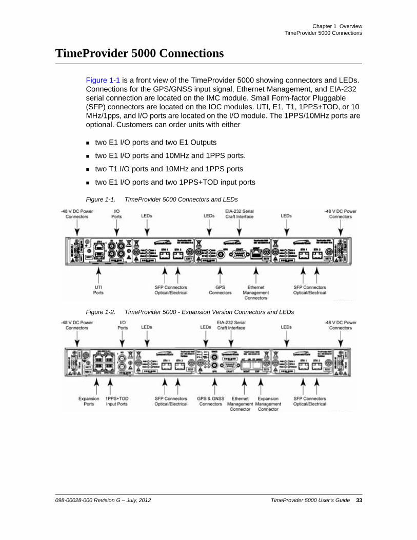
Figure 1-1 is a front view of the TimeProvider 5000 showing connectors and LEDs. Connections for the GPS/GNSS input signal, Ethernet Management, and EIA-232 serial connection are located on the IMC module. Small Form-factor Pluggable (SFP) connectors are located on the IOC modules. UTI, E1, T1, 1PPS+TOD, or 10 MHz/1pps, and I/O ports are located on the I/O module. The 1PPS/10MHz ports are optional. Customers can order units with either
two E1 I/O ports and two E1 Outputs
two E1 I/O ports and 10MHz and 1PPS ports.
two T1 I/O ports and 10MHz and 1PPS ports
two E1 I/O ports and two 1PPS+TOD input ports
Figure 1-1. TimeProvider 5000 Connectors and LEDs
Figure 1-2. TimeProvider 5000 - Expansion Version Connectors and LEDs
098-00028-000 Revision G – July, 2012 TimeProvider 5000 User’s Guide 33
Chapter 1 OverviewTimeProvider 5000 Connections
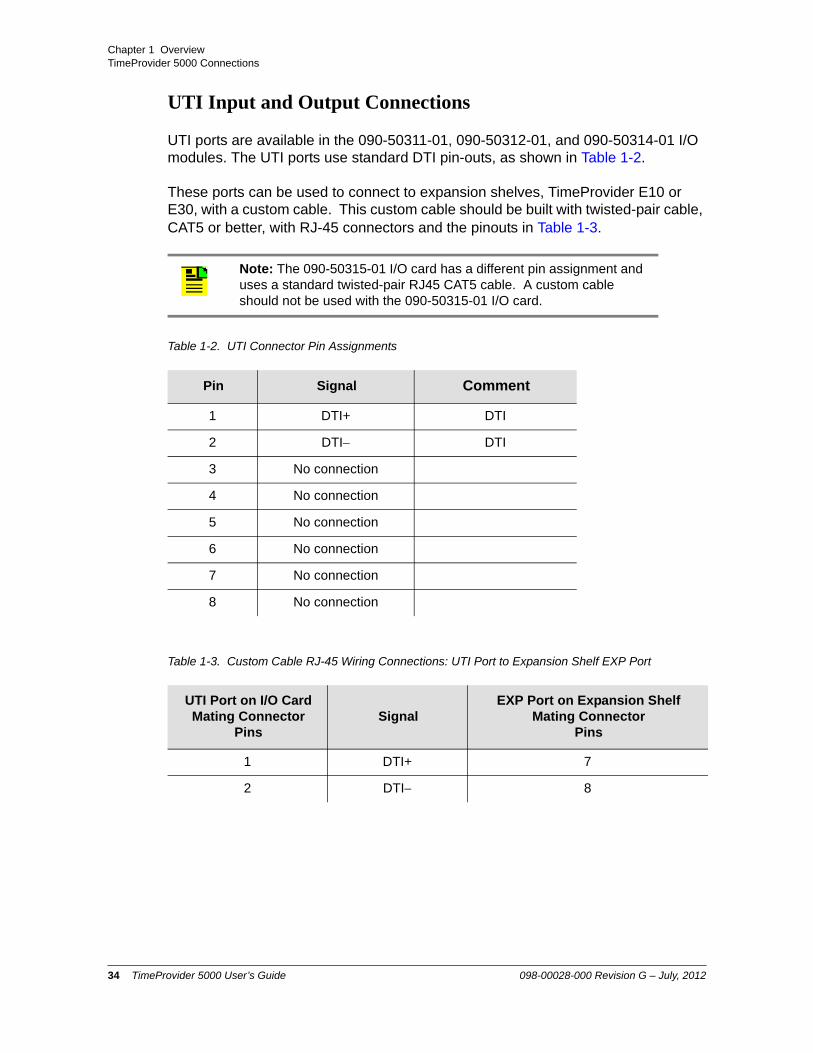
UTI Input and Output Connections
UTI ports are available in the 090-50311-01, 090-50312-01, and 090-50314-01 I/O modules. The UTI ports use standard DTI pin-outs, as shown in Table 1-2.
These ports can be used to connect to expansion shelves, TimeProvider E10 or E30, with a custom cable. This custom cable should be built with twisted-pair cable, CAT5 or better, with RJ-45 connectors and the pinouts in Table 1-3.
Note: The 090-50315-01 I/O card has a different pin assignment and uses a standard twisted-pair RJ45 CAT5 cable. A custom cable should not be used with the 090-50315-01 I/O card.
Table 1-2. UTI Connector Pin Assignments
Pin Signal Comment
1 DTI+ DTI
2 DTI DTI
3 No connection
4 No connection
5 No connection
6 No connection
7 No connection
8 No connection
Table 1-3. Custom Cable RJ-45 Wiring Connections: UTI Port to Expansion Shelf EXP Port
UTI Port on I/O CardMating Connector
PinsSignal
EXP Port on Expansion ShelfMating Connector
Pins
1 DTI+ 7
2 DTI 8
34 TimeProvider 5000 User’s Guide 098-00028-000 Revision G – July, 2012

Chapter 1 OverviewTimeProvider 5000 Connections
Communications Connections
The IMC allows user control of the TimeProvider 5000 through either the Ethernet Management port or the EIA-232 serial port.
Ethernet Management PortThe Ethernet Management port on the IMC is standard 10/100Base-T shielded RJ-45 receptacle. To connect the TimeProvider 5000 to an Ethernet network, use a standard twisted-pair Ethernet RJ-45 cable (CAT5 minimum).
Expansion Management PortThe expansion Management port on the IMC is a standard 10/100Base-T shielded RJ-45 receptacle. To connect the TimeProvider 5000 to a TP E10 or TPE30 expansion shelf, use a standard twisted-pair Ethernet RJ-45 cable (CAT5 minimum).
The connector pinouts for the expansion Management port, and all expansion ports, are listed in Table 1-4.
Table 1-4. Expansion RJ-45 Connector Pin Assignments
Pin Signal Comment
1 RX+(Receive positive)
Ethernet (10/100Base-T)
2 RX (Receive negative)
Ethernet (10/100Base-T)
3 TX+ (Transmit positive)
Ethernet (10/100Base-T)
4 Reserved
5 Reserved
6 TX (Transmit negative)
Ethernet (10/100Base-T)
7 DTI+ DTI
8 DTI DTI
098-00028-000 Revision G – July, 2012 TimeProvider 5000 User’s Guide 35

Chapter 1 OverviewTimeProvider 5000 Connections
Figure 1-3. IMC Module: Versions -01 through -05
EIA-232 Serial (Craft) PortThe EIA-232 serial port connection is made through a EIA-23 female connector on the IMC. This port allow you to connect to a terminal or computer using a terminal emulation software package. When connecting to this port, use a shielded EIA-232 direct connect cable.
36 TimeProvider 5000 User’s Guide 098-00028-000 Revision G – July, 2012

Chapter 1 OverviewTimeProvider 5000 Connections
Figure 1-4 shows the EIA-232 male connector pin assignments for the serial port.
Figure 1-4. Serial Port Male Connector Pins
Table 1-5 describes the EIA-232 connector pin assignments for the serial port.
Output Connections
Programmable E1 Output ConnectionsTwo of the traditional telecom synchronization coaxial ports (Port1 and Port2) on the 090-50311-01, 090-50312-01, and 090-50315-01 versions of the I/O module (Figure 1-5) are software configurable as E1 output ports, with the following signal types:
2.048 Mb/s (G.703/9)
2.048 MHz (G.703/13)
These ports can also be software configured as E1 inputs.
E1 Output ConnectionsTwo of the four traditional telecom synchronization mini-BNC ports (Port3 and Port4) on the 090-50311-01 version of the I/O module (Figure 1-5) are dedicated E1 output ports, with the following signal types:
2.048 Mb/s (G.703/9)
2.048 MHz (G.703/13)
Programmable T1 Output ConnectionsTwo of the RJ-48C ports (I/O-1 and I/O-2) on the 090-50314-01 version of the I/O module (Figure 1-6) are software configurable as T1 output ports, with the following signal types:
Table 1-5. Serial Port Connector Pin Assignments
Signal Pin
TXD (Received Data) 2
RXD (Transmitted Data) 3
Ground 5
098-00028-000 Revision G – July, 2012 TimeProvider 5000 User’s Guide 37

Chapter 1 OverviewTimeProvider 5000 Connections
1.544 Mb/s (G.703)
1.544 MHz (G.703)
These ports can also be software configured as T1 outputs .
Table 1-6 shows the pin assignments for the RJ-48C connectors for the programmable T1 input/output ports.
10MHz & 1PPS Output ConnectionsTwo of the four mini-BNC ports (Port3 and Port4) on the 090-50312-01 version of the I/O module are 1PPS and 10MHz output ports. See Figure 1-5.
Port3 and Port4 on the 090-50314-01 version of the I/O module are also 1PPS and 10MHz dedicated output ports. See Figure 1-6.
Note: The T1 ports on the 090-50314-01 version of the I/O module can also be configured as E1 and 2048 kHz inputs or outputs which meet the G.703 mask for impedance of 120 ohms, balanced.
Table 1-6. T1 Input/Output Port Pin-Outs - RJ48C Connector
Pin Signal
1 Rx Ring
2 Rx Tip
3 NC
4 Tx Ring
5 Tx Tip
6 NC
7 NC
8 NC
Note: Units that provide 1PPS and 10MHz outputs must be ordered from the factory; they cannot be reconfigured in the field. One port provides 1PPS output and one port provides 10 MHz output.
38 TimeProvider 5000 User’s Guide 098-00028-000 Revision G – July, 2012
Chapter 1 OverviewTimeProvider 5000 Connections
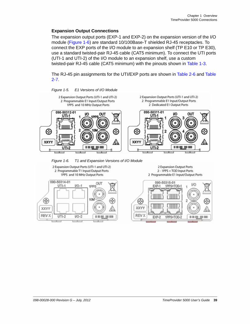
Expansion Output ConnectionsThe expansion output ports (EXP-1 and EXP-2) on the expansion version of the I/O module (Figure 1-6) are standard 10/100Base-T shielded RJ-45 receptacles. To connect the EXP ports of the I/O module to an expansion shelf (TP E10 or TP E30), use a standard twisted-pair RJ-45 cable (CAT5 minimum). To connect the UTI ports (UTI-1 and UTI-2) of the I/O module to an expansion shelf, use a custom twisted-pair RJ-45 cable (CAT5 minimum) with the pinouts shown in Table 1-3.
The RJ-45 pin assignments for the UTI/EXP ports are shown in Table 2-6 and Table 2-7.
Figure 1-5. E1 Versions of I/O Module
Figure 1-6. T1 and Expansion Versions of I/O Module
098-00028-000 Revision G – July, 2012 TimeProvider 5000 User’s Guide 39

Chapter 1 OverviewTimeProvider 5000 Connections
PTP / NTP Output ConnectionsThe TimeProvider 5000 provides two Ethernet 100/1000 Small-form Factor Pluggable (SFP) connections on each IOC (see Figure 1-5) module. In PTP (IEEE 1588v2) grand-master mode, the TimeProvider 5000 supports many slaves per system in unicast mode, multicast mode, or multicast-hybrid mode. In NTP server mode, the TimeProvider 5000 supports 20,000 transactions/second (120,000 transactions/second with high-capacity NTP option).
Figure 1-7. PTP Output Connections
Input Connections
E1 Input ConnectionsMini-BNC ports 1 and 2 on the 090-50311-01, 090-50312-01, and 090-50315-01 versions of the I/O module (see Figure 1-5) are software configurable as traditional telecom input ports with the following signal types:
2.048 Mb/s (G.703/9)
2.048 MHz (G.703/13)
These ports can also be software configured as E1 outputs.
T1 Input ConnectionsTwo of the RJ-45 ports (I/O-1 and I/O-2) on the 090-50314-01 version of the I/O module (Figure 1-6) are software configurable as traditional T1 telecom input ports with the following signal types:
1.544 Mb/s (G.703)
1.544 MHz (G.703)
These ports can also be software configured as T1 outputs.
Note: The T1 ports on the 090-50314-01 version of the I/O module can also be configured as E1 and 2048 kHz inputs or outputs which meet the G.703 mask for impedance of 120 ohms, balanced.
40 TimeProvider 5000 User’s Guide 098-00028-000 Revision G – July, 2012

Chapter 1 OverviewTimeProvider 5000 Connections
1PPS+TOD Input ConnectionsTwo of the RJ-45 ports (1PPS+TOD-1 and 1PPS+TOD-2) on the 090-50315-01 expansion version of the I/O module (Figure 1-6) are input ports for 1PPS and TOD information transmitted at RS-422 level. See Table 1-7 for pin-outs for the 1PPS+TOD connectors.
GNSS ConnectionThe IMC (versions 090-50331-04 and 090-50331-05) has an SMA connector for input from GPS (090-50331-05) and Beidou/GPS (090-50331-04) navigation satellites to provide a frequency and time reference (see Figure 1-3). This port supports input from both GPS and Beidou satellites for the 090-50331-04 version of the IMC and input from GPS satellites for the 090-50331-05 version.
GPS ConnectionThe IMC (versions 090-50331-01, 090-50331-02, 090-50331-04, and 090-50331-05) has an SMA connector for GPS input to provide a frequency and time reference (see Figure 1-3).
Table 1-7. 1PPS+TOD Port Pin-Outs - RJ45 Connector
Pin Signal Comment
1 No Connection Default state is open (high impedance)
2 No Connection Default state is open (high impedance)
3 422_1_N 1PPS
4 GND RS422 GND
5 GND RS422 GND
6 422_1_P 1PPS
7 422_2_N TOD time information
8 422_2_P TOD time information
098-00028-000 Revision G – July, 2012 TimeProvider 5000 User’s Guide 41

Chapter 1 OverviewTimeProvider 5000 Connections
Power and Ground Connections
The TimeProvider 5000 uses –48 VDC power and is not equipped with a Power switch; DC power is controlled by a power distribution panel connected to the power connectors. Frame ground connections on the TP 5000 are made on the grounding stud located on the left side of the front panel, as identified with the international Ground marking, as shown in Figure 1-8. Frame ground connections on the TP E10 and TP E30 expansion shelves are made on the grounding stud located on the right side of the front panel (see Figure 1-9 and Figure 1-10).
Figure 1-8. TimeProvider 5000 Power and Ground
Figure 1-9. TimeProvider E10 Power amd Ground
Figure 1-10. TimeProvider E30 Power and Ground
Warning: To avoid serious personal injury or death, exercise caution when working near high voltage lines and follow local building electrical codes for grounding the chassis.
42 TimeProvider 5000 User’s Guide 098-00028-000 Revision G – July, 2012

Chapter 1 OverviewPhysical Description
Physical Description
The TimeProvider 5000 consists of a 19-inch (48 cm) rack mount chassis, plug-in modules, and hardware. The TP E10 and TP E30 each consist of a 19-inch (48 cm) rack mount chassis and hardware.
The TimeProvider 5000 has one I/O module slot, two IOC module slots, and one IMC module slot. The grounding lug is located near the I/O module and the power supply connectors are located on both sides of the chassis (see Figure 1-11). The minimum configuration is an I/O module, an IOC module, and an IMC module. The second IOC module slot is available for redundancy. See TimeProvider 5000 Part Numbers, on page 414.
The TimeProvider E10 SyncE/PTP expansion shelf has one block of RJ-45 expansion connectors (2 Input ports, 2 Output ports), two blocks of Gigabit SFP connectors (16 ports). The shelf also has six LEDs located on the left side of the front panel. The shelf features a recessed rotary switch with 10 positions that is used to set the shelf ID and a recessed reset switch. The grounding lug is located on the right side of the front panel. The power supply connectors are located on both sides of the chassis (see Figure 1-12).
The TimeProvider E30 E1/1PPS+TOD expansion shelf has one block of RJ-45 expansion Input/Output connectors (2 Input ports, 2 Output ports), two blocks of SMB output connectors (12 ports), and three blocks of RJ-45 output connectors (12 ports). The shelf also has six LEDs located on the left side of the front panel. The grounding lug is located on the right side of the front panel. The power supply connectors are located on both sides of the chassis (see Figure 1-13).
Note: The TP 5000, TP E10, and TP E30 comes equipped with 19-inch rack mounting brackets. 23-inch (58.42 cm) rack mounting adapters are also available as a separately ordered item. 21-inch (ETSI) rack mounting adapters are available as a separately ordered item.
098-00028-000 Revision G – July, 2012 TimeProvider 5000 User’s Guide 43

Chapter 1 OverviewPhysical Description
Figure 1-11. TimeProvider 5000 Modules and Power Connections
Figure 1-12. TimeProvider E10 Expansion Shelf Connections
Figure 1-13. TimeProvider E30 Expansion Shelf Connections
44 TimeProvider 5000 User’s Guide 098-00028-000 Revision G – July, 2012

Chapter 1 OverviewFunctional Description
Functional Description
See Figure 1-14 below for a block diagram of the TimeProvider 5000.
Figure 1-14. TimeProvider 5000 Block Diagram
TimeProvider 5000 Expansion Shelf System
The TimeProvider 5000 expansion shelf system consists of a TP5000 with expansion versions of the IMC and I/O cards, a new TimeProvider E10 output expansion shelf with Gigabit SyncE/PTP ports, and a new TimeProvider E30 output expansion shelf with E1 and 1PPS+TOD ports.
The TP 5000 expansion shelf system supports two IOC cards in 1+1 redundant configuration. These two IOC cards track one or more of the time and frequency reference inputs and provide the stable time and frequency signals that are used to generate output synchronization signals. The 090-50331-04 version of the IMC supports the Beidou satellite system. The 090-50301-02 chassis, 090-50315-01 I/O module and the 090-50331-02, 090-50331-04, and 090-50331-05 versions of the IMC will support 1PPS+TOD inputs. The 090-50331-02, 090-50331-04, and 090-50331-05 versions of the IMC support the expansion shelves.
Functionally the TimeProvider 5000 system can be thought of as a BITS or SSU in a central office or a secondary office. It accepts time and frequency reference inputs in multiple formats, and it provides time and frequency synchronization signals to the network equipment in the office.
Figure 1-16 shows the physical interfaces of a typical TimeProvider 5000 expansion shelf system that consists of a TP5000 and two output expansion shelves.
098-00028-000 Revision G – July, 2012 TimeProvider 5000 User’s Guide 45

Chapter 1 OverviewFunctional Description
The TP5000 has four primary functions in the system:
Input shelf for the system
Timing synchronization source to expansion shelves using DTI
External management interface
Controller for the expansion shelves in the system.
In the TimeProvider 5000 expansion shelf system, expansion shelves are primarily output shelves. They use the time and frequency information from the TP5000 and convert them to different synchronization signal formats. Symmetricom offers two types of expansion shelves for the TP5000: the TimeProvider E30 expansion shelf provides E1 and 1PPS+TOD outputs and the TimeProvider E10 expansion shelf provides PTP and SyncE outputs. More outputs can be added by adding appropriate expansion shelves.
Expansion ConnectionsThe TP 5000 provides time and frequency to the expansion shelves through DTI links in the expansion interface. The TP5000 controls and manages the expansion shelves through Ethernet in the expansion interface. The Ethernet management link and the DTI links share the same physical RJ-45 connector but they are logically two separate networks.
Figure 1-15. Expansion Connector on Expansion Shelf
Figure 1-15 shows the Expansion connector on the expansion shelves. Figure 1-18 is a block diagram of the TimeProvider E30 E1/1PPS+TOD expansion shelf. Figure 1-17 is a block diagram of the TimeProvider E10 SyncE/PTP expansion shelf.
46 TimeProvider 5000 User’s Guide 098-00028-000 Revision G – July, 2012

Chapter 1 OverviewFunctional Description
Figure 1-16. Physical Interfaces of TP 5000 with Two Expansion Shelves
Figure 1-17. TimeProvider E10 SyncE/PTP Expansion Shelf Block Diagram
098-00028-000 Revision G – July, 2012 TimeProvider 5000 User’s Guide 47

Chapter 1 OverviewFunctional Description
Figure 1-18. TimeProvider E30 E1/1PPS+TOD Expansion Shelf Block Diagram
The following actions must be performed to support the use of expansion shelves with the TP 5000.
Enable ETH on TP 5000 IMC module’s DTI / ETH connector to allow communication with the expansion shelves
Set a unique ID (0-9) for each expansion shelf using the rotary switch on its front panel
Enable DTI
– TP 5000 - IMC
– TP 5000 - I/O
– Expansion shelf
Provision output signals for each expansion shelf
Enable state(s) of output(s)
The following actions must be performed to support the use of expansion shelves with the TP 5000.
Enable ETH on TP 5000 IMC module’s DTI / ETH connector to allow communication with the expansion shelves
Set a unique ID (0-9) for each expansion shelf using the rotary switch on its front panel
Enable DTI
48 TimeProvider 5000 User’s Guide 098-00028-000 Revision G – July, 2012

Chapter 1 OverviewFunctional Description
– TP 5000 - IMC
– TP 5000 - I/O
– Expansion shelf
Provision output signals for each expansion shelf
Enable state(s) of output(s)
Figure 1-19 is a diagram of the expansion connections for a TP 5000 with one expansion shelf. Figure 1-20 is a diagram of the expansion connections for a TP 5000 with 5 expansion shelves.
Figure 1-19. Expansion Connections for TP 5000 with a Single Expansion Shelf
Note: If using UTI ports from I/O modue 090-50311-01, 090-50312-01, or 090-50314-01, a custom cable must be used between the I/O module and the expansion shelf. See Table 2-9 for details.
098-00028-000 Revision G – July, 2012 TimeProvider 5000 User’s Guide 49

Chapter 1 OverviewFunctional Description
Figure 1-20. Expansion Connections for TP 5000 with 5 Expansion Shelves
50 TimeProvider 5000 User’s Guide 098-00028-000 Revision G – July, 2012

Chapter 1 OverviewFunctional Description
IMC Module LEDs
The IMC module provides connectors for 10/100 Ethernet management, EIA-232 serial management, and the GPS/GNSS Timing Antenna. The IMC’s LEDs indicate the following:
Power Module Status
Battery A & B Status
System Health Status
Alarm Status
GPS/GNSS Signal Status
IOC Module LEDs
The IOC module also has two PTP Grand Master 100/1000 Ethernet SFP ports with LEDs that indicate link and link speed. The IOC module has LED status indicators and test outputs for the system. The LEDs indicate:
Power Status
Active Status
Ethernet Status
Alarm Status
Holdover Status
Expansion Shelf LEDs
The TP E10 expansion shelf has sixteen (16) 100/1000 Ethernet SFP ports with LEDs that indicate link and link speed.The TP E30 has twelve (12) 1PPS ports with LEDs that indicate port enable state. The TP E10 and TP E30 also each have LED status indicators. The LEDs indicate:
Power Status
Active Status
Ethernet Status
Alarm Status
Holdover Status
098-00028-000 Revision G – July, 2012 TimeProvider 5000 User’s Guide 51

Chapter 1 OverviewFunctional Description
Communication Ports
Communications ports on the IMC allow you to provision, monitor, and troubleshoot the chassis. You can communicate with the TimeProvider 5000 using either CLI or SNMP protocols.
Local Craft Serial PortThe EIA-232 port supports local control; you can configure the TimeProvider 5000 with CLI commands using a terminal or computer with terminal emulation software. The connector is located on the IMC module. The Local port is configured as a DCE interface and the default settings are as follows:
Baud = 57.6K
Data Bits = 8 bits
Parity = 0
Stop bits = 1
Flow Control, None
Management Ethernet PortThe Management Ethernet connector provides connectivity to an Ethernet local area network. Each Ethernet port has a unique internet protocol (IP) address and once the IP address is set and a connection is made to a LAN, you can access the TimeProvider 5000.
Synchronization and Timing Inputs
The TimeProvider 5000 can use either GPS, Beidou, E1, T1, or 1PPS+TOD signals as external input references. The GPS and GPS/Beidou references connect to SMA connectors on the IMC card. The GPS/Beidou port is labeled "GNSS". The E1 and T1 inputs are configurable ports located on the I/O module. The 1PPS+TOD input ports are located on the 090-50315-01 version of the I/O module.
Synchronization and Timing Outputs
The TimeProvider 5000 has four GbE timing outputs (2 per IOC card), which can be configured as either Precision Timing Protocol (PTP) or Network Timing Protocol (NTP) outputs. The expansion version of the I/O card, 090-50315-01, also features two DTI timing outputs that are used to provide timing to expansion shelves.
Note: The SNMP feature can either be ordered in a new system, or added to a previously ordered system as a field upgrade (see Table 6-7 for part number). Contact your Symmetricom representative for more information.
52 TimeProvider 5000 User’s Guide 098-00028-000 Revision G – July, 2012

Chapter 1 OverviewFunctional Description
System Inputs and Outputs
Programmable Input/Output PortsThe TimeProvider 5000 has two mini-BNC ports on the 090-50311-01 and 090-50312-01 versions of the I/O module, and two SMB ports on the 090-50315-01 version, that are software configurable as either E1 input or output ports. They can provide or receive the following signal types:
2.048 Mb/s (G.703/9)
2.048 MHz (G.703/13)
The 090-50314-01 version of the I/O module has two RJ-45 ports that are software configurable as either T1 input or output ports. They can provide or receive the following signal types:
1.544 Mb/s (G.703)
1.544 MHz (G.703)
The 090-50315-01 version of the I/O module has two RJ-45 input ports for 1PPS and TOD information transmitted at RS-422 level
Dedicated Output PortsThe 090-50311-01 version of the I/O module (Figure 1-5) also has two mini-BNC ports that are dedicated E1 output ports with the following signal types:
2.048 Mb/s (G.703/9)
2.048 MHz (G.703/13)
The 090-50312-01 (see Figure 1-5) and 090-50314-01 (see Figure 1-6) versions of the I/O module also have two mini-BNC ports that are dedicated output ports with the following signal types:
1PPS
10 MHz
Note: Units that provide 1PPS/10MHz output must be configured at the factory when ordered; they cannot be reconfigured in the field. One port provides 1PPS output and one port provides 10MHz output.
098-00028-000 Revision G – July, 2012 TimeProvider 5000 User’s Guide 53

Chapter 1 OverviewFunctional Description
TP E10 Expansion Shelf System Outputs
PTP/SyncE Output PortsThe TP E10 expansion shelf features 16 output ports with SyncE/PTP signals.
1PPS Output PortThe TP E10 expansion shelf includes one 1PPS SMB female output port.
TP E30 Expansion Shelf System Outputs
E1 Output PortsThe TP E30 expansion shelf features 12 dedicated E1 output ports with the following signal types:
2.048 Mb/s (G.703/9)
2.048 MHz (G.703/13)
1PPS+TOD Output Ports The TP E30 expansion shelf features 12 1PPS+TOD output ports. 1PPS and TOD information is transmitted at RS-422 level.
Expansion Shelf ID Switch
Each expansion shelf must have a unique user-defined shelf ID. There can be up to 10 shelf IDs (0 to 9) in the system. The user can set the shelf ID using a mechanical rotary switch on the front panel.
Figure 1-21. Shelf ID Selector
54 TimeProvider 5000 User’s Guide 098-00028-000 Revision G – July, 2012

Chapter 1 OverviewConfiguration Management
Configuration Management
The Command Line Interface (CLI), also called the ASCII command set, can be used to control the TimeProvider 5000 from a terminal connected to the EIA-232 serial port, or the Ethernet port. Refer to Chapter 3, CLI Commands and SNMP for further details.
Alarms
The TP5000 uses alarms to notify you when certain conditions are deteriorating below specified levels. Expansion shelf alarms are reported to the TP 5000 that controls the shelf. These alarms are indicated by module status LEDs and by SNMP traps. You can provision the alarm to either be enabled or disabled and the current alarm state can be obtained via the communication ports. For more information, see Provisioning Alarms, on page 361 and Appendix A, System Messages.
Note: Before you can communicate with the TimeProvider 5000 through an Ethernet connection, you must first configure the Ethernet port using the serial connection (see Provisioning the Ethernet Ports, on page 293).
098-00028-000 Revision G – July, 2012 TimeProvider 5000 User’s Guide 55

Chapter 1 OverviewAlarms
56 TimeProvider 5000 User’s Guide 098-00028-000 Revision G – July, 2012

Chapter 2 Installing
This chapter describes the procedures for installing the TimeProvider 5000, as well as the TimeProvider E10 and TimeProvider E30 expansion shelves.
In This Chapter
Getting Started
Unpacking the Unit
Rack Mounting the Chassis
– Rack Mounting the TimeProvider 5000 Main Shelf
– Rack Mounting the TP E10 & TP E30 Expansion Shelves
Working With Modules
Signal Connections
– Communications Connections
– TP 5000 Synchronization and Timing Connections
– TimeProvider E10 Synchronization and Timing Connections
– TimeProvider E30 Synchronization and Timing Connections
Connecting the GPS/GNSS Antenna
Making Ground and Power Connections
Installation Check List
Applying Power to the TimeProvider 5000
098-00028-000 Revision G – July, 2012 TimeProvider 5000 User’s Guide 57

Chapter 2 InstallingGetting Started
Getting Started
Before you begin to install the TimeProvider 5000, TimeProvider E10 or TimeProvider E30, review the information in this section.
If you encounter any difficulties during the installation process, contact Symmetricom Global Services (SGS). See Contacting Technical Support, on page 421 for telephone numbers. Contact SGS - Product Technical Support for technical information. Contact Customer Service for information about your order, RMAs, and other information.
Security Considerations for TP5000 Installation
The TP 5000, TP E10 and TP E30 should be installed in a physically secure location.
The TP 5000's IMC Module's Ethernet port should be installed behind the company's firewall to prevent public access.
Whenever possible, the TP 5000's Ethernet service ports should be installed behind the company's firewall to prevent public access.
Site Survey
Before you begin installation, determine the chassis location, ensure the appropriate power source is available (–48 VDC), and ensure that the equipment rack is properly grounded.
The TimeProvider 5000 is designed to mount in a 19-inch (48 cm) rack, occupies 1.75 in (4.5 cm, 1 RU) of vertical rack space, and has a depth of 18 in (45.7 cm). The TimeProvider E10 and TimeProvider E30 expansion shelves are also designed to mount in a 19-inch (48 cm) rack, and each occupies 1.75 in (4.5 cm, 1 RU) of vertical rack space, and has a depth of 10 in (25.4 cm). .
The TimeProvider 5000 is to be installed into a rack with permanent connection to the -48VDC mains. This connection is to be made to a branch over-current, short-circuit protection device with replaceable fusing of 5 amps, maximum. For permanently connected equipment a readily accessible disconnect device shall be incorporated in the building installation wiring.
Note: 1RU above the TimeProvider 5000 must be left unoccupied for heat dissipation
Note: 23-inch (58.42 cm) rack mounting adapters are also available as a separately ordered item. 21-inch (ETSI) rack mounting adapters are available as a separately ordered item.
58 TimeProvider 5000 User’s Guide 098-00028-000 Revision G – July, 2012

Chapter 2 InstallingGetting Started
The TimeProvider E10 expansion shelf is to be installed into a rack with permanent connection to the -48VDC mains. This connection is to be made to a branch over-current, short-circuit protection device with replaceable fusing of 2 amps, maximum. For permanently connected equipment a readily accessible disconnect device shall be incorporated in the building installation wiring.
The TimeProvider E30 expansion shelf is to be installed into a rack with permanent connection to the -48VDC mains. This connection is to be made to a branch over-current, short-circuit protection device with replaceable fusing of 1 amp, maximum. For permanently connected equipment a readily accessible disconnect device shall be incorporated in the building installation wiring.
Environmental RequirementsTo prevent the unit from malfunctioning or interfering with other equipment, install and operate the unit according to the following guidelines:
Operating temperature: 23Fto 113F (–5 C to 45C) for TP 500023Fto 131F (–5 C to 55C) for TP E10 and TP E30
Operating Humidity: 90% to 100% RH, maximum, w/condensation
Use only shielded cable for all signal wiring, including I/O, clocks and Ethernet. Ground appropriately at both ends, or as required by local standards.
Secure all cable screws to their corresponding connectors.
Installation Tools and Equipment
You will need the following tools and equipment to install the TimeProvider 5000:
Standard tool kit
Cable ties, waxed string or acceptable cable clamps
1 mm² / 18 AWG (minimum) stranded wire at 300 volt insulation for –48 VDC
1 mm² / 16 AWG wire to connect grounding lug to permanent earth ground
Two U.L listed Ring Lugs for grounding connections
Crimping tool to crimp the ring lug
Caution: To avoid interference, you must consider the electromagnetic compatibility (EMC) of nearby equipment when you install the TP 5000, TP E10 and TP E30.
Electromagnetic interference can adversely affect the operation of nearby equipment.
098-00028-000 Revision G – July, 2012 TimeProvider 5000 User’s Guide 59

Chapter 2 InstallingUnpacking the Unit
Shielded cabling of the appropriate impedance required by the specific signal type for signal wiring (including GPS, and Ethernet)
Mating connectors for terminating signal wiring
ESD wrist strap for installing modules
Fasteners for mounting the equipment in rack
Digital multimeter or standard Voltmeter for verifying power connections to the chassis
Laptop computer with communications software (e.g., Microsoft Hyperterminal, ProComm Plus or EmTec ZOC) for setting system parameters
Unpacking the Unit
The TimeProvider 5000, TimeProvider E10 and TimeProvider E30 are packaged to protect them from normal shock, vibration and handling damage.(Each unit is packaged separately.)
Unpack and inspect the unit as follows:
1. Wear a properly grounded protective wrist strap or other ESD device.
2. Inspect the container for signs of damage. If the container appears to be damaged, notify both the carrier and your Symmetricom distributor. Retain the shipping container and packing material for the carrier to inspect.
3. Open the container, being careful to cut only the packaging tape.
4. Locate and set aside the CD, printed information, and paperwork that is included in the container.
5. Remove the unit from the container and place it on an anti-static surface.
6. Locate and set aside small parts which may be packed in the container.
7. Remove the accessories from the container.
8. Remove the anti-static packaging from the unit and accessories.
9. Verify that the model and item number shown on the shipping list agrees with the model and item number on the equipment. The item number can be found on a label affixed to the top of the unit, front and center. See Figure 2-1 for the location of the label on the TP 5000. See Figure 2-2 for the location of the label on the TP
Caution: To avoid electrostatic discharge (ESD) damage to parts that are packaged with the TP 5000, TP E10 and TP E30, observe the following procedures.
60 TimeProvider 5000 User’s Guide 098-00028-000 Revision G – July, 2012

Chapter 2 InstallingUnpacking the Unit
E10. See Figure 2-3 for the location of the label on the TP E30. Contact your Symmetricom distributor if the model or item number do not match.
For a complete listing of item numbers, see Table 6-7 and Table 6-8.
Figure 2-1. TP 5000 - Location of Product Label
Figure 2-2. TP E10 - Location of Product Label
Figure 2-3. TP E30 - Location of Product Label
098-00028-000 Revision G – July, 2012 TimeProvider 5000 User’s Guide 61

Chapter 2 InstallingRack Mounting the Chassis
Rack Mounting the Chassis
The installation procedure described in this section provides general guidelines for installing the TimeProvider 5000, as well as theTimeProvider E10 and TimeProvider E30 expansion shelves. Always follow applicable local electrical standards.
Rack Mounting the TimeProvider 5000 Main Shelf
Use the following steps to mount the TimeProvider 5000 in a rack.
1. TimeProvider 5000 is shipped with rack mounting brackets attached. The rack mounting brackets can be removed and reattached in a different orientation, if desired. See Figure 2-4 for mounting hole placements. See Figure 2-5 and Figure 2-6 for chassis dimensions. Ensure that the mounting brackets on both sides are attached to the chassis at equal distances from the front of the unit (see Figure 2-7) using 6-32 x 1/4-inch screws.
2. Mount the chassis to the front of the equipment rack rails with four screws and associated hardware. Use the proper screws for the equipment rack.
Note: 1RU above the TimeProvider 5000 must be left unoccupied for heat dissipation.
Note: The TimeProvider 5000 comes equipped with 19-inch rack mounting brackets. 23-inch (58.42 cm) rack mounting adapters are also available as a separately ordered item. 21-inch (ETSI) rack mounting adapters are available as a separately ordered item.
62 TimeProvider 5000 User’s Guide 098-00028-000 Revision G – July, 2012

Chapter 2 InstallingRack Mounting the Chassis
Figure 2-4. TP 5000 Mounting Hole Placements
Figure 2-5. TP 5000 Chassis Dimensions Front View
Figure 2-6. TP 5000 Chassis Dimensions Top View
098-00028-000 Revision G – July, 2012 TimeProvider 5000 User’s Guide 63

Chapter 2 InstallingRack Mounting the Chassis
Figure 2-7. Rack Mounting the TimeProvider 5000
Rack Mounting the TP E10 & TP E30 Expansion Shelves
Use the following steps to mount the TP E10 or TP E30 expansion shelf in a rack.
1. The TP E10 and TP E30 are shipped with rack mounting brackets attached. The rack mounting brackets can be removed and reattached in a different orientation, if desired. See Figure 2-8 for mounting hole placements. See Figure 2-9, Figure 2-10 and Figure 2-11 for chassis dimensions. Ensure that the mounting brackets on both sides are attached to the chassis at equal distances from the front of the unit (see Figure 2-12 for the TP E10, Figure 2-13 for the TP E30) using 6-32 x 1/4-inch screws.
2. Mount the chassis to the front of the equipment rack rails with four screws and associated hardware. Use the proper screws for the equipment rack.
Note: The TP E10 and TP E30 come equipped with 19-inch rack mounting brackets. 23-inch (58.42 cm) rack mounting adapters are also available as a separately ordered item. 21-inch (ETSI) rack mounting adapters are available as a separately ordered item.
64 TimeProvider 5000 User’s Guide 098-00028-000 Revision G – July, 2012

Chapter 2 InstallingRack Mounting the Chassis
Figure 2-8. TP E10 and TP E30 Mounting Hole Placements - Side View
Figure 2-9. TP E10 Chassis Dimensions - Front View
Figure 2-10. TP E30 Chassis Dimensions - Front View
098-00028-000 Revision G – July, 2012 TimeProvider 5000 User’s Guide 65
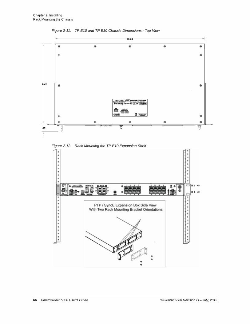
Chapter 2 InstallingRack Mounting the Chassis
Figure 2-11. TP E10 and TP E30 Chassis Dimensions - Top View
Figure 2-12. Rack Mounting the TP E10 Expansion Shelf
66 TimeProvider 5000 User’s Guide 098-00028-000 Revision G – July, 2012

Chapter 2 InstallingWorking With Modules
Figure 2-13. Rack Mounting the TP E30 Expansion Shelf
Working With Modules
This section describes how to install, remove, and handle the modules associated with the TimeProvider 5000.
Handling Modules
When handling any of the modules, observe the following precautions:
1. Use proper static control precautions when handling modules! Protect the equipment against ESD (electrostatic discharge) by using a grounded protective wrist strap and normal equipment grounding.
2. Avoid touching component leads and edge connectors.
3. Avoid placing the module on an ungrounded surface.
4. Avoid allowing the module to come in contact with insulated surfaces.
098-00028-000 Revision G – July, 2012 TimeProvider 5000 User’s Guide 67

Chapter 2 InstallingSignal Connections
Inserting Modules
This procedure is common for all modules in the TimeProvider 5000.
Use the following procedure to insert a module into the chassis:
1. Align the module edges within the guides of the selected slot.
2. Slide the module into the chassis and press firmly until it seats fully into its backplane edge connector.
3. Tighten the captive screws located on each side of the panel.
Removing Modules
To remove a module from the TimeProvider 5000, loosen the screws and then pull out the module. Be sure to place the module on a static-free surface.
Signal Connections
The connectors for the GPS and GNSS input signal, Ethernet management, expansion connections, and EIA-232 serial connection are located on the IMC module. The PTP output connectors are located on the IOC module. The E1, T1, 1PPS+TOD, 10 MHz, 1PPS, Expansion, and UTI connectors are located on different versions of the I/O module.
Caution: All modules can be removed and inserted while system power is supplied without damaging modules; however, system performance may be affected.
Note: The I/O card does not have captive screws and requires a Phillips screwdriver.
Caution: To avoid possible damage or intermittent failures, ensure that you have completely inserted the module into the chassis and that you have securely tightened the captive screws.
Caution: You must disconnect the antenna (GPS and/or Beidou) before removing the IMC module.
68 TimeProvider 5000 User’s Guide 098-00028-000 Revision G – July, 2012

Chapter 2 InstallingSignal Connections
Communications Connections
The IMC allows user control of the TimeProvider 5000. The EIA-232 serial port and Ethernet Management port are located on the IMC as shown in Figure 2-14. See Working With Modules, on page 67 for module installation instructions.
Figure 2-14. IMC Module Versions -01 through -05
System Management (MGMT) Port The System Management port is standard 10/100Base-T shielded RJ-45 receptacle. To connect the TimeProvider 5000 to an Ethernet network, use an Ethernet RJ-45 cable. See Table 2-1 for connector pinouts.
098-00028-000 Revision G – July, 2012 TimeProvider 5000 User’s Guide 69

Chapter 2 InstallingSignal Connections
Expansion PortThe expansion ports are standard 10/100Base-T shielded RJ-45 receptacles. To connect the TimeProvider 5000 to an expansion shelf (TP E30 E1/1PPS+TOD or TP E10 SyncE/PTP, use a standard twisted pair Ethernet RJ-45 cable (CAT5 minimum). The Ethernet management link and the DTI links share the same physical RJ-45 connector, as shown in Figure 2-14, but they are logically two separate networks. The expansion port from the IMC must always be used when using expansion shelves to provide management messages via Ethernet. (The expansion ports on the I/O card only provide DTI.)
Figure 2-20 shows the expansion connections for a TP 5000 with a single expansion shelf, with redundant DTI connections from the expansion ports on the IMC and I/O cards. Figure 2-21 shows the expansion connections for a TP 5000 with five expansion shelves. Redundant DTI connections for the IN1 and IN2 ports on each expansion shelf are used to protect against various failure scenarios.
The connector pinouts are listed in Table 2-2.
Table 2-1. System Management Ethernet Connector Pin Assignments
Signal Name Pin
TX+ (Transmit positive) 1
TX- (Transmit negative) 2
RX- (Receive negative) 3
RX+ (Receive positive) 6
Not Used 4, 5, 7, 8
Table 2-2. DTI/Ethernet RJ-45 Connector Pin Assignments
Pin Signal Comment
1 RX+(Receive positive)
Ethernet (10/100Base-T)
2 RX (Receive negative)
Ethernet (10/100Base-T)
3 TX+ (Transmit positive)
Ethernet (10/100Base-T)
4 Reserved
5 Reserved
70 TimeProvider 5000 User’s Guide 098-00028-000 Revision G – July, 2012

Chapter 2 InstallingSignal Connections
EIA-232 Serial (Craft) PortThe EIA-232 serial port connection is made through a EIA-232 female connector on the IMC. This ports allow you to connect to a terminal or computer using a terminal emulation software package for remote monitoring and control. When connecting to this port, use a shielded EIA-232 direct connect cable.
Figure 2-15 shows the EIA-232 male connector pin assignments for the serial port.
Figure 2-15. Serial Port Male Connector Pins
Table 2-3 describes the EIA-232 connector pin assignments for the serial port.
TP 5000 Synchronization and Timing Connections
The basic version TimeProvider 5000 has one GPS input on the IMC module and two redundant PTP timing outputs on each IOC module. There are also four connections on the I/O module, two of which can be outputs or inputs and two connections that are dedicated outputs. The version of the I/O module determines the configuration of the I/O connections:
6 TX (Transmit negative)
Ethernet (10/100Base-T)
7 DTI+ DTI
8 DTI DTI
Table 2-3. Serial Port Connector Pin Assignments
Signal Pin
TXD (Received Data) 2
RXD (Transmitted Data) 3
Ground 5
Table 2-2. DTI/Ethernet RJ-45 Connector Pin Assignments (Continued)
Pin Signal Comment
098-00028-000 Revision G – July, 2012 TimeProvider 5000 User’s Guide 71
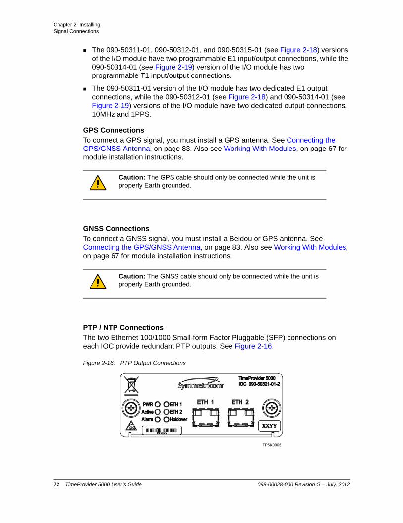
Chapter 2 InstallingSignal Connections
The 090-50311-01, 090-50312-01, and 090-50315-01 (see Figure 2-18) versions of the I/O module have two programmable E1 input/output connections, while the 090-50314-01 (see Figure 2-19) version of the I/O module has two programmable T1 input/output connections.
The 090-50311-01 version of the I/O module has two dedicated E1 output connections, while the 090-50312-01 (see Figure 2-18) and 090-50314-01 (see Figure 2-19) versions of the I/O module have two dedicated output connections, 10MHz and 1PPS.
GPS ConnectionsTo connect a GPS signal, you must install a GPS antenna. See Connecting the GPS/GNSS Antenna, on page 83. Also see Working With Modules, on page 67 for module installation instructions.
GNSS ConnectionsTo connect a GNSS signal, you must install a Beidou or GPS antenna. See Connecting the GPS/GNSS Antenna, on page 83. Also see Working With Modules, on page 67 for module installation instructions.
PTP / NTP ConnectionsThe two Ethernet 100/1000 Small-form Factor Pluggable (SFP) connections on each IOC provide redundant PTP outputs. See Figure 2-16.
Figure 2-16. PTP Output Connections
Caution: The GPS cable should only be connected while the unit is properly Earth grounded.
Caution: The GNSS cable should only be connected while the unit is properly Earth grounded.
72 TimeProvider 5000 User’s Guide 098-00028-000 Revision G – July, 2012

Chapter 2 InstallingSignal Connections
Only the SFP transceivers in Table 2-4 are recommended and supported. Other SFP transceivers are not supported and may cause the TimeProvider 5000 to not comply with regulatory requirements. Figure 2-17 shows a typical optical SFP transceiver.
Figure 2-17. Optical SFP Transceiver
Figure 2-18. Output Connections for E1 Versions of I/O Module
Table 2-4. Recommended and Supported SFP Transceivers
Type Transceiver
Optical 1000 Base-LX Single-Mode Ethernet 1310nm (Symmetricom 121-20621-10-2)
Avago AFCT-5701PZFinisar FTLF1319P1BTL
Optical 1000 Base-SX Multi-Mode Ethernet 850nm (Symmetricom 121-20621-11-2)
Avago AFBR-5710PZFinisar FTLF8519P2BNL
RJ45 100/1000/1GbE Base-T Full-Duplex(Symmetricom 121-20621-12-2)
Avago ABCU-5710RZ
Note: Recommended and supported SFP connectors comply with FDA radiation performance standards, 21 CFR Subchapter J.
098-00028-000 Revision G – July, 2012 TimeProvider 5000 User’s Guide 73

Chapter 2 InstallingSignal Connections
Figure 2-19. Output Connections for T1 and Expansion Versions of I/O Module
E1 ConnectionsTwo of the four coaxial ports on the 090-50311-01 and 090-50312-01, and 090-50315-01 versions of the I/O module (see Figure 2-18 and Figure 2-19) are software configurable as either E1 input or output ports. These ports are mini-BNC male ports, except for the 090-50315-01, which uses SMB male connectors. They can provide or receive the following signal types:
2.048 Mb/s (G.703/9)
2.048 MHz (G.703/13)
The 090-50311-01 version of the I/O module (Figure 2-18) also has two mini-BNC male ports that are dedicated E1 output ports with the following signal types:
2.048 Mb/s (G.703/9)
2.048 MHz (G.703/13)
T1 ConnectionsThe 090-50314-01 version of the I/O module has two RJ-45 ports that are software configurable as either T1 input or output ports (see Figure 2-19). They can provide or receive the following signal types:
1.544 Mb/s (G.703)
1.544 MHz (G.703)
Note: Amphenol mini-BNC connectors (031-70261) can be used to create cables. Alternatively, Symmetricom sells a kit of 4 mini-BNC to BNC adapter cables (093-00068-000).
Note: The T1 ports on the 090-50314-01 version of the I/O module can also be configured as E1 and 2048 kHz inputs or outputs which meet the G.703 mask for impedance of 120 ohms, balanced.
74 TimeProvider 5000 User’s Guide 098-00028-000 Revision G – July, 2012

Chapter 2 InstallingSignal Connections
1PPS & 10MHz ConnectionsThe 090-50312-01 (see Figure 2-18) and 090-50314-01 (see Figure 2-19) versions of the I/O module also have two mini-BNC male ports that are dedicated output ports with the following signal types:
1PPS
10 MHz
Expansion ConnectionsThe TP5000 provides timing to the expansion shelves through two DTI links. The 090-50315-01 version of the I/O card features two standard shielded RJ-45 receptacles, labeled EXP-1 and EXP-2, as shown in Figure 2-19. The 090-50311-01, 090-50312-01, 090-50314-01 versions of the I/O card feature two standard shielded RJ-45 receptacles, labeled UTI-1 and UTI-2, as shown in Figure 2-18 and Figure 2-19, which are also used for DTI signals. The expansion shelves use the time and frequency information from the TP5000 and convert them to different synchronization signal formats.
To connect the expansion (EXP) ports on the 090-50315-01 version of the TP 5000 I/O card to an expansion shelf (TP E10 or TP E30), use a standard twisted pair Ethernet RJ-45 cable, CAT5 or better. See Table 2-6 for pin-outs for the EXP expansion RJ-45 connectors on the I/O card.
Table 2-5. T1 Input/Output Port Pin-Outs - RJ48C Connector
Pin Signal
1 Rx Ring
2 Rx Tip
3 NC
4 Tx Ring
5 Tx Tip
6 NC
7 NC
8 NC
Note: Units that provide 1PPS/10MHz output must be configured at the factory when ordered; they cannot be reconfigured in the field. One port provides 1PPS output and one port provides 10MHz output.
098-00028-000 Revision G – July, 2012 TimeProvider 5000 User’s Guide 75

Chapter 2 InstallingSignal Connections
To connect the expansion (UTI) ports on the 090-50311-01, 090-50312-01, and 090-50314-01 versions of the TP 5000 I/O card to an expansion shelf (TP E10 or TP E30), use a custom cable. See Table 2-7 for pin-outs for the UTI expansion RJ-45 connectors on the I/O card. See Table 2-8 for pin-outs for the EXP expansion RJ-45 connectors on the expansion shelves. The custom cable should be built with twisted-pair cable, CAT5 or better, with RJ-45 connectors and the custom mating connector pinouts in Table 2-9.
Figure 2-20 shows the expansion connections for a TP 5000 with a single expansion shelf, with redundant DTI connections from the expansion ports on the IMC and I/O cards. Figure 2-21 shows the expansion connections for a TP 5000 with five expansion shelves. Redundant DTI connections for the IN1 and IN2 ports on each expansion shelf are used to protect against various failure scenarios.
The expansion port from the IMC must always be used when using expansion shelves to provide management messages via Ethernet. (The expansion ports on the I/O card only provide DTI.)
Note: If using UTI ports from I/O modue 090-50311-01, 090-50312-01, or 090-50314-01, a custom cable must be used between the I/O module and the expansion shelf. See Table 2-9 for details.
Table 2-6. Expansion Port (EXP) RJ-45 Connector Pin Assignments - I/O Card
Pin Signal Comment
1 No connection
2 No connection
3 No connection
4 No connection
5 No connection
6 No connection
7 DTI+ DTI
8 DTI DTI
76 TimeProvider 5000 User’s Guide 098-00028-000 Revision G – July, 2012

Chapter 2 InstallingSignal Connections
.
.
Table 2-7. UTI Port RJ-45 Connector Pin Assignments - I/O Card
Pin Signal Comment
1 DTI+ DTI
2 DTI DTI
3 No connection
4 No connection
5 No connection
6 No connection
7 No connection
8 No connection
Table 2-8. EXP Port RJ-45 Connector Pin Assignments - TP E10 & TP E30 Expansion Shelves
Pin Signal Comment
1 RX+(Receive positive)
Ethernet (10/100Base-T)
2 RX (Receive negative)
Ethernet (10/100Base-T)
3 TX+ (Transmit positive)
Ethernet (10/100Base-T)
4 Reserved
5 Reserved
6 TX (Transmit negative)
Ethernet (10/100Base-T)
7 DTI+ DTI
8 DTI DTI
098-00028-000 Revision G – July, 2012 TimeProvider 5000 User’s Guide 77

Chapter 2 InstallingSignal Connections
.
Figure 2-20. DTI and DTI/ETH Connection for TP 5000 and One Expansion Shelf
Table 2-9. Custom Cable RJ-45 Wiring Connections: UTI Port to Expansion Shelf EXP Port
UTI Port on I/O CardMating Connector
PinsSignal
EXP Port on Expansion ShelfMating Connector
Pins
1 DTI+ 7
2 DTI 8
78 TimeProvider 5000 User’s Guide 098-00028-000 Revision G – July, 2012

Chapter 2 InstallingSignal Connections
Figure 2-21. DTI and DTI/ETH Connection for TP 5000 and Five Expansion Shelves
098-00028-000 Revision G – July, 2012 TimeProvider 5000 User’s Guide 79

Chapter 2 InstallingSignal Connections
1PPS +TOD ConnectionsThe expansion version of the I/O card, p/n 090-50315-01, features 2 RJ-45 connectors, as shown in Figure 2-18. These ports are dedicated input ports with 1PPS+TOD signals. See Table 2-10 for pin-outs for these RJ-45 connectors. See Table 2-11 for TOD default parameters.
Table 2-10. 1PPS+TOD Port Pin-Outs - RJ45 Connector
Pin Signal Comment
1 No Connection Default state is open (high impedance)
2 No Connection Default state is open (high impedance)
3 422_1_N 1PPS
4 GND RS422 GND
5 GND RS422 GND
6 422_1_P 1PPS
7 422_2_N TOD time information
8 422_2_P TOD time information
Table 2-11. Default Parameters for TOD Information Transmission
Pin Default Comment
Baud Rate 9600 Cannot be changed
Parity Check None
Start Bit 1 (low level)
Stop Bit 1 (high level)
Idle Frame High level
Data Bits 8
80 TimeProvider 5000 User’s Guide 098-00028-000 Revision G – July, 2012

Chapter 2 InstallingSignal Connections
TimeProvider E10 Synchronization and Timing Connections
The TimeProvider 5000 features 16 SFP output ports (see Figure 2-22). These ports can provide the following signal types:
PTP (IEEE-1588 2008)
SyncE (only accessible with optical SFP)
TP E10 - PTP/SyncE ConnectionsThe TP E10 expansion shelf features 16 SFP output ports (see Figure 2-22). These ports can provide the following signal types:
PTP (IEEE-1588 2008)
SyncE (only accessible with optical SFP)
These ports are dedicated output ports with PTP signals that meet the IEEE-1588 v2 specifications. As with the two PTP ports on each TP 5000 IOC card, these 16 ports require Ethernet SFP connectors.
Figure 2-22. TP E10 - Output Connections for PTP/SyncE
Only the SFP transceivers in Table 2-4 are recommended and supported. Other SFP transceivers are not supported and may cause the TP E10 expansion shelf to not comply with regulatory requirements. SyncE is only available with optical SFP transceivers.
Since the TP E10 expansion shelf uses PTP multicast, all 16 ports should be on isolated Ethernet networks. Otherwise, only one of the ports will be the active grandmaster due to the IEEE-1588 BMC algorithm
TP E10 - 1PPS ConnectionThe TP E10 expansion shelf also has an SMA connector that is a dedicated output port with a 1PPS signal.
Figure 2-23. TP E10 - Output Connection for 1PPS Signal
098-00028-000 Revision G – July, 2012 TimeProvider 5000 User’s Guide 81

Chapter 2 InstallingSignal Connections
TimeProvider E30 Synchronization and Timing Connections
TP E30 - E1 ConnectionsThe TP E30 expansion shelf features 12 SMB output ports (see Figure 2-18). These ports can provide the following signal types:
2.048 Mb/s (G.703/9, G.704)
2.048 MHz (G.703/13, G.704)
Figure 2-24. TP E30 - Output Connections for E1 Signals
TP E30 - 1PPS +TOD ConnectionsThe TP E30 expansion shelf features 12 RJ-45 connectors, as shown in Figure 2-18. See Table 2-5 for pin-outs for these RJ-45 connectors. See Table 2-11 for TOD default parameters.
Figure 2-25. TP E30 - Output Connections for 1PPS+TOD
Table 2-12. TP E30 - 1PPS+TOD Port Pin-Outs - RJ45 Connector
Pin Signal Comment
1 No Connection Default state is open (high impedence)
2 No Connection Default state is open (high impedence)
3 422_1_N 1PPS
4 GND RS422 GND
82 TimeProvider 5000 User’s Guide 098-00028-000 Revision G – July, 2012

Chapter 2 InstallingConnecting the GPS/GNSS Antenna
See Appendix B, Specifications and Factory Defaults for additional information about the TOD signal.
Connecting the GPS/GNSS Antenna
The antenna connections for the TP 5000 are made at the IMC module connector labeled GPS or GNSS. Allow at least one hour for the unit to track and lock to GPS/GNSS.
5 GND RS422 GND
6 422_1_P 1PPS
7 422_2_N TOD time information
8 422_2_P TOD time information
Table 2-13. TP E30 - Default Parameters for TOD Information Transmission
Pin Default Comment
Baud Rate 9600
Parity Check None
Start Bit 1 (low level)
Stop Bit 1 (high level)
Idle Frame High level
Data Bits 8
Caution: The GPS and GNSS cables should only be connected while the unit is properly Earth grounded.
Table 2-12. TP E30 - 1PPS+TOD Port Pin-Outs - RJ45 Connector (Continued)
Pin Signal Comment
098-00028-000 Revision G – July, 2012 TimeProvider 5000 User’s Guide 83

Chapter 2 InstallingSetting Shelf ID on Expansion Shelves
Proper cable, grounding techniques, and lightning arrestors should be used. Mount the antenna outside, preferably on the roof with a clear view of the sky. Do not mount the antenna near a wall or other obstruction blocking part of the sky. Mount the antenna well above roads or parking lots.
Setting Shelf ID on Expansion Shelves
Set the shelf ID on the TP E10 or TP E30 expansion shelf using a small flat-blade screwdriver to turn the mechanical rotary switch on the front panel. See Figure 2-26. Each expansion shelf must be provided a unique user-defined shelf ID. There can be up to 10 shelf IDs (0 to 9) in the system.
Figure 2-26. Shelf ID Selector
Making Ground and Power Connections
The TimeProvider 5000 has two –48 VDC power connectors for redundant operation, which are located on the right and left sides of the front panel (see Figure 2-27). A separate frame ground terminal is on the left side of the front panel.
The TP E10 and TP E30 expansion shelves each have two –48 VDC power connectors for redundant operation, which are located on the right and left sides of the front panel (see Figure 2-28 and Figure 2-29). A separate frame ground terminal is provided on the right side of the front panel.
Warning: To avoid serious personal injury or death, exercise caution when working near high voltage lines. In particular:
Use extreme caution when installing the antenna near, under, or around high voltage lines.
Follow local building electrical codes for grounding the chassis.
Note: If 2 systems are assigned the same shelf ID, then management capability will be lost and an alarm will be generated on the TP 5000 shelf.
Warning: To avoid accidental power-up of the chassis, remove the A and B fuses on the branch over-current protection unit before beginning installation of the TP 5000, TP E10, and/or TP E30. These units are not equipped with a power on/off switch.
84 TimeProvider 5000 User’s Guide 098-00028-000 Revision G – July, 2012

Chapter 2 InstallingMaking Ground and Power Connections
Ground Connections
Frame ground connections are made using the M4 Grounding Terminal Stud, which is marked with the universal ground symbol, as shown in Figure 2-30. This stud is located on the left side of the front panel for the TP 5000, and on the right side of the front panel for the TP E10 and TP E30.
Figure 2-27. TimeProvider 5000 Power Connections
Figure 2-28. TimeProvider E10 Power Connections
Figure 2-29. TimeProvider E30 Power Connections
Figure 2-30. Universal Ground Symbol
098-00028-000 Revision G – July, 2012 TimeProvider 5000 User’s Guide 85

Chapter 2 InstallingMaking Ground and Power Connections
After installing the TimeProvider 5000 into the rack, connect the chassis to the proper grounding zone or master ground bar. Run a 16 AWG green/yellow-striped insulated wire from the TimeProvider 5000 grounding terminal to the Earth Ground on the rack. The rack grounding method is below.
1. Crimp the customer-supplied UL listed Ring Lug to one end of the 16 AWG wire and connect it to the ground terminal on the left side of the front panel using the supplied M4 Kept machine nut. The surface of the TimeProvider 5000 Earth grounding terminal must be clean of contaminants and oxidation.
2. Crimp the appropriate customer-supplied UL listed Ring Lug to the other end of the 1 mm² / 16 AWG green/yellow-striped wire. Remove the paint and sand the area around the screw hole to ensure the proper conductivity. Coat the connection with an electrically conductive antioxidant compound such as Kopr-shield spray. Connect this Ring Lug to the rack with appropriate customer supplied screws and external star lock washers.
3. Using a digital voltmeter, measure between the ground and chassis and verify that no voltage exists between them.
Power Connections
Use the following procedure to make the power connections:
1. Ensure the power source is turned off.
2. Connect the frame ground terminal to earth ground.
3. Locate the power connectors included in the installation kit, Phoenix Contact p/n MC 1,5/2-STF-3,81.
Recommendation: Although there are a number of methods for connecting the equipment to earth ground, Symmetricom recommends running a cable of the shortest possible length from the ground lug to earth ground.
Warning: To avoid possible damage to equipment, you must provide power source protective fusing as part of the installation. The TimeProvider 5000, TimeProvider E10 and TimeProvider E30 are intended for installation in a restricted-access location.
Caution: To avoid damage to the unit, remove the fuses in the fuse panel which provides power to the TimeProvider 5000, TimeProvider E10 and TimeProvider E30 before making power connections.
86 TimeProvider 5000 User’s Guide 098-00028-000 Revision G – July, 2012

Chapter 2 InstallingMaking Ground and Power Connections
4. Using 1 mm² / 18 AWG (minimum) stranded wire, connect primary power to the connectors per the polarity markings. Use the polarity markings of "-48V" and "RTN" as a reference for the proper polarity connection..
5. Insert the connectors into the power connections in the chassis. See Figure 2-31. Tighten screws in the connector
Figure 2-31. TimeProvider 5000 Power Connector
Figure 2-32. TP E10 and TP E30 - Power Connector A
Figure 2-33. TP E10 and TP E30 - Power Connector B
Note: The -48VDC power must be connected with the proper polarity. The unit will not be damaged by reverse polarity, but the unit will not operate if the polarity is reversed.
098-00028-000 Revision G – July, 2012 TimeProvider 5000 User’s Guide 87

Chapter 2 InstallingMaking Ground and Power Connections
Testing Power Connections
To verify that the power connections to the TimeProvider 5000 are correct, follow the steps in this section. The connections on the primary power module of the TP 5000 are referred to as Power A and Return A. The connections on the secondary power module are referred to as Power B and Return B. Use a digital multimeter (Fluke 77 or equivalent) to make the measurements.
1. Remove all fuses that supply power to the unit from the fuse panel.
2. Ensure that no IOC or IMC modules are installed in the unit.
3. Disconnect the -48V battery leads from the unit’s power connector terminals. See the primary and secondary power connections in Figure 2-34. Leave the Return battery leads connected to the unit.
Figure 2-34. Power and Ground Connections on the TimeProvider 5000
4. At the chassis end of the battery leads, use the multimeter to measure the voltage between the following test points:
Test Point Test Point ResultBattery A lead Battery B lead 0 VBattery A lead Primary: Return A 0 VBattery A lead Earth Ground 0 VBattery B lead Secondary: Return B 0 VBattery B lead Earth Ground 0 V
5. Reconnect the –48V battery A and battery B leads to the –48V A and –48V B terminal connectors.
6. Install the A fuse in the power source fuse panel.
7. Measure the voltage between the –48V A and Return terminals on the primary power module. The multimeter should indicate –42 VDC to –56 VDC.
8. Install the B fuse in the power source fuse panel.
9. Measure the voltage between the –48V B and Return terminals on the secondary power module. The multimeter should indicate –42 VDC to –56 VDC.
88 TimeProvider 5000 User’s Guide 098-00028-000 Revision G – July, 2012

Chapter 2 InstallingInstallation Check List
The unit is now powered up.
Installation Check List
To verify that the installation of the TimeProvider 5000 is complete, perform the checks and procedures in Table 2-14.
Applying Power to the TimeProvider 5000
The TimeProvider 5000 is not equipped with a Power switch. DC power is controlled by a power distribution panel. After installing the unit in a rack and making the necessary connections described in previous sections, turn on power at the distribution panel.
The TP E10 and TP E30 expansion shelves are not equipped with Power switches. DC power is controlled by a power distribution panel. After installing a unit in a rack and making the necessary connections described in previous sections, turn on power at the distribution panel.
Normal Power Up Indications
As the TimeProvider 5000 powers up and begins normal operation, the IOC module and IMC module LEDs all turn on. After the module self-test is complete and the module firmware is operational, the LED states may change to indicate the appropriate state or status.
As the TP E10 or TP E30 expansion shelves powers up and begins normal operation, the LEDs all turn on. After the self-test is complete and expansion shelf firmware is operational, LED states may change to indicate appropriate state or status.
Table 2-15 provides a description of the module LEDs. Table 2-16 provides a description of the expansion shelf LEDs.
Table 2-14. Installation Completeness Checklist
Operation Complete
Ensure the TimeProvider 5000 chassis is securely attached to mounting rack
Ensure that the appropriate modules (and filler panels if needed) are installed
Verify that all power and ground wires are installed correctly and securely
Verify that all communications cables are properly installed
Verify that all input and output cables are properly installed
098-00028-000 Revision G – July, 2012 TimeProvider 5000 User’s Guide 89

Chapter 2 InstallingApplying Power to the TimeProvider 5000
Table 2-15. Module LED Descriptions
LED Label Description
IMC Module
PowerModule Power Indicator
PWR Green - Module power availableOff - Module power not available
-48V A-BusA-Bus Battery Indicator
BT A Off - A-Bus power OKRed - A-Bus power failed
-48V B-BusB-Bus Battery Indicator
BT B Off - B-Bus power OKRed - B-Bus power failed
System HealthAggregation of system alarms indicator
SYS Off - System operating normallyAmber - System operational Minor Alarm(s)Red - System operational Major or Critical Alarm(s)
IMC AlarmIMC module alarm/fault indicator
ALM Off - IMC operating normallyAmber - IMC operational Minor Alarm(s)Red - IMC operational Major/Critical Alarm(s)Flashing Green - Software starting up
GNSS/GPS StatusGPS engine status indicator
GNSS/GPS
Green - GPS enabled and GPS engine/interface is operating normallyAmber - GPS enabled and GPS engine or antenna interface has operational issuesOff - GPS disabled
Ethernet Management PortLEDs on the Ethernet connector
MGMT Left Flashing Amber - ActivityLeft Off - No ActivityRight Green - Link has been establishedRight Off - Link has not been established
Expansion PortLEDs on the RJ48 connector
EXP Left OFF - No DTI client detectedLeft Amber - DTI client detectedLeft Green - DTI client detected and ready
Right OFF- Link has not been establishedRight Green - Link has been establishedRight Flashing Green - Activity
IOC Module
PowerModule Power Indicator
PWR Green - Module power availableOff - Module power not available
90 TimeProvider 5000 User’s Guide 098-00028-000 Revision G – July, 2012

Chapter 2 InstallingApplying Power to the TimeProvider 5000
ActiveIndicates which IOC is responsible for generating PTP, Telecom, 10MHz, and 1PPS outputs
ACT Off - Standby IOC or System StartupGreen - Active IOC
IOC AlarmIOC module alarm/fault indicator
ALM Off - IOC operating normallyAmber - IOC operational Minor Alarm(s)Red - IOC has Failed or has Major/Critical Alarm(s)Flashing Green - Software starting up
Ethernet Port 1ETH1 link/activity indicator
ETH1 Green - Link has been establishedFlashing Green - Link activityOff - Link has not been established
Ethernet Port 2ETH2 port link/activity indicator
ETH2 Green - Link has been establishedFlashing Green - Link activityOff - Link has not been established
Local Oscillator StateIndicates the current mode of operation of the LO servo
HOLD Off - Oscillator is operating in Locked modeAmber - Oscillator is operating in Holdover or Acquire modesFlashing Amber - Oscillator is operating in Warm-up mode
Expansion PortLEDs on the RJ48 connector
EXP-1/EXP-2
Left OFF - No DTI client detectedLeft Amber - DTI client detectedLeft Green - DTI client detected and ready
Table 2-16. Expansion Shelf LED Descriptions
LED Label Description
PowerModule Power Indicator
PWR Green - Power availableOff - Power not available
-48V A-BusA-Bus Battery Indicator
BT A Green - A-Bus power OKRed - A-Bus power failed
-48V B-BusB-Bus Battery Indicator
BT B Green - B-Bus power OKRed - B-Bus power failed
AlarmAlarm/fault indicator
ALM Off - Operating normallyAmber - Operational Minor Alarm(s)Red - Operational Major/Critical Alarm(s)
Ethernet Management Port MGMT This LED is not used.See LED labeled “MGMT “ on TP5000 IMC card.
Table 2-15. Module LED Descriptions (Continued)
LED Label Description
098-00028-000 Revision G – July, 2012 TimeProvider 5000 User’s Guide 91

Chapter 2 InstallingApplying Power to the TimeProvider 5000
Reference Indicator REF Off - Oscillator is operating in Locked modeAmber - Oscillator is operating in Holdover or Acquire modesFlashing Amber - Oscillator is operating in Warm-up mode
Expansion PortsLEDs on the RJ48 connectors
EXPAN-SION
Input Ports
Left OFF - No DTI signalLeft Green - Link has been established , DTI signal valid and stableLeft Flashing Green - Active, DTI signal stable and qualifiedLeft Amber - DTI signal detected but not stableLeft Flashing Amber - DTI signal detected but not selected
Right OFF- Link has not been establishedRight Green - Link has been establishedRight Flashing Green - Activity
Output PortsLeft OFF - No DTI client detectedLeft Amber - DTI client detectedLeft Green - DTI client detected and ready
Right OFF- Link has not been establishedRight Green - Link has been establishedRight Flashing Green - Activity
Table 2-16. Expansion Shelf LED Descriptions (Continued)
LED Label Description
92 TimeProvider 5000 User’s Guide 098-00028-000 Revision G – July, 2012

Chapter 3 CLI Commands and SNMP
This chapter describes the CLI command conventions, the prompts, line editing functions, and command syntax. The CLI command functions and features are organized by user security access levels and are listed alphabetically. This chapter also describes the SNMP option.
In This Appendix
CLI Overview
TimeProvider 5000 CLI Command Set
Simple Network Management Protocol (SNMP)
098-00028-000 Revision G – July, 2012 TimeProvider 5000 User’s Guide 93

Chapter 3 CLI Overview
CLI Overview
The Command Line Interface (CLI), also called the ASCII command set, can be used to control the TimeProvider 5000 from a terminal connected to the EIA-232 serial port, or the Ethernet port. See Figure 3-1 below for an overview of the TP5000 command set.
Figure 3-1. TimeProvider 5000 CLI Command Set
94 TimeProvider 5000 User’s Guide 098-00028-000 Revision G – July, 2012

Chapter 3CLI Overview
TimeProvider 5000 CLI Command Conventions
The following are conventions used for the TimeProvider 5000 CLI command set .
Commands are case sensitive
{ } Braces indicate more than one parameter data option. When entering options in the CLI command, enter one option from those available within the braces. Options within braces { } are separated by a pipe ( | ).
[ ] Brackets provide information about the allowed range. The first value is the minimum, and the last value is the maximum.
Bold highlights keywords in the command syntax
Italics indicate variable options.
CLI Command Keyboard Usage
You must press the SPACE key, and then press the TAB key after entering a CLI command. Also, after entering a command, you may see <enter>. This is a prompt for you to press ENTER to execute the command that you entered.
The interface has built-in features for navigating within the CLI command hierarchy, which are as follows:
The TAB key can be used at any time while typing a command (including at the prompt) to provide continuation options. Press the TAB key to display a list of the available commands. Press the TAB key at any time while typing a command TimeProvider 5000 will respond with the completion of the keyword or available completion choices based on the letters you typed.
The ? (SHIFT+QUESTION MARK) accesses the CLI online help. It can be used at any time while typing a command (including at the prompt) to provide continuation options. These options include brief descriptions of commands, or data type, format, and range.
If typing of a keyword is partially complete, the completion will display if it is unique, otherwise, the completion choices will be available.
If the keyword is complete, and you press the TAB key or ? (SHIFT+QUESTION MARK), the choices for the next syntax element will display.
In the following example, if you press the TAB key, or the ? (SHIFT+QUESTION MARK), after typing s, the CLI commands set, set-timeout, show, and sync display.
Typing s at the prompt:
tp5000> s
Then pressing the TAB key :
set set-timeout show sync
098-00028-000 Revision G – July, 2012 TimeProvider 5000 User’s Guide 95

Chapter 3 CLI Overview
Or pressing the ? (SHIFT+QUESTION MARK)will display the available commands that start with s (for this example) and brief descriptions of those commands:
set -Set TP5000 information or setting
show -Display TP5000 information or setting
sync -Synchronize the TOD source
set-timeout-Set the inactivity timeout to the defined seconds
Previously typed commands can be recalled by using the UP ARROW key. You can recall up to five previously typed commands. Continually pressing the UP ARROW key will cycle you through the five previously typed commands. After pressing the UP ARROW key five times, you will go back to the last command you previously typed. Use the DOWN ARROW key to cycle the five prior typed commands in the opposite direction.
You can use the BACKSPACE to correct keystroke errors, or to reuse parts of a previously typed command. When using BACKSPACE, the removed characters will still appear on the screen, but they have been removed to the position shown by the cursor. When you start typing, the removed characters are overwritten.
Command Line Format
The command line format is as follows:
[Verb] Command [Parameter] [Data] EOL
Verb - the type of action to be taken with the command.
– Set - enables you to provision a defined parameter.
– Show - enables you to display the provisioned state of a parameter.
Parameter - command input that defines the particular command element to be shown or modified.
Data - the data input for the parameter.
EOL - this parser responds only to <CR Return>. When the parser receives <CR Return>, the input is terminated, and the command line entry is processed.
For all commands that indicate a specific port on an IOC card, the port will be referred to as IOC-[y] or IOC1-[y] in the command description, where y=1 or 2. If port redundancy is enabled, the bonded port will use the configuration for port 1 (y=1) for all commands.
96 TimeProvider 5000 User’s Guide 098-00028-000 Revision G – July, 2012

Chapter 3TimeProvider 5000 CLI Command Set
Command User Levels
The TimeProvider 5000 provides a hierarchy of CLI command user levels that permit an increasing level of access to system parameters. This allows the system administrator to add users who can only view but not change system parameters and users who can view and change system parameters.
The users assigned to each security level have access options available as follows:
Level 1 - user class, with read-only rights
Level 2 - config user class, with read-write rights
Level 3 - administrator user class, with read-write rights and can also configure users and upgrade firmware
TimeProvider 5000 CLI Command Set
This section provides an alphabetical listing and details of all CLI commands.
show alarm
Displays the system's standing (active) alarms and events.
Command Syntax:
show {alarm | event}
Example:
tp5000> show alarm
Response:
ID Mod Severity Date-Time Descriptions---------------------------------------------------------7 IOC Minor 2009-06-08 23:38:59 ETH2 Port link down
Remarks: The information displayed is expected to be identical to an entry in the Event/Alarm Log File.
Level : User, Config, and Admin
098-00028-000 Revision G – July, 2012 TimeProvider 5000 User’s Guide 97

Chapter 3 TimeProvider 5000 CLI Command Set
show alarm-config
Displays the alarm ID, level, state, description, and reporting delay time for the TP5000 alarms. This also displays if the alarm is transitory.
Command Syntax:
show alarm-config
Example:
tp5000> show alarm-config
Response :
------------------------------------------------------------------------------|ID |Level |Delay |State |Descriptions|----|---------|-------|--------|---------------------------------------------|0 |critical |0 |enable |Communication to peer card failed|....|.........|.......|........|.............................................|1 |minor |0 |enable |GNSS/GPS receiver communications failed|....|.........|.......|........|.............................................|2 |minor |0 |enable |GNSS/GPS receiver not tracking satellite|....|.........|.......|........|.............................................|3 |major |0 |enable |System time invalid|....|.........|.......|........|.............................................|4 |event |0 |enable |System time has been set by reference|....|.........|.......|........|.............................................|5 |event |0 |enable |System log time has been updated|....|.........|.......|........|.............................................|6 |minor |0 |enable |Management port link down|....|.........|.......|........|.............................................|7 |minor |0 |disable |Ethernet port link down|....|.........|.......|........|.............................................|8 |minor |0 |enable |Manual sync IOC time to IMC required|....|.........|.......|........|.............................................|9 |critical |0 |enable |Power out of range|....|.........|.......|........|.............................................|10 |major |0 |enable |GPS antenna voltage out of range|....|.........|.......|........|.............................................|11 |major |0 |enable |GPS antenna current out of range|....|.........|.......|........|.............................................|12 |minor |0 |enable |GNSS/GPS antenna short-circuit|....|.........|.......|........|.............................................|13 |minor |0 |enable |GNSS/GPS antenna open-circuit|....|.........|.......|........|.............................................|14 |major |0 |disable |Battery(-48V)-A failure|....|.........|.......|........|.............................................|15 |major |0 |disable |Battery(-48V)-B failure|....|.........|.......|........|.............................................|16 |critical |0 |enable |FPGA access failure|....|.........|.......|........|.............................................|17 |critical |0 |enable |Flash partition failure|....|.........|.......|........|.............................................|18 |critical |0 |enable |PLL unlock error|....|.........|.......|........|.............................................
98 TimeProvider 5000 User’s Guide 098-00028-000 Revision G – July, 2012
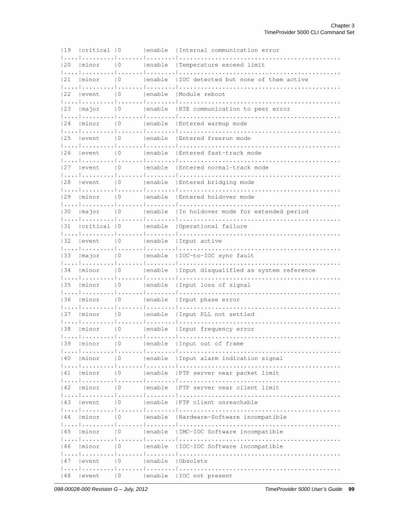
Chapter 3TimeProvider 5000 CLI Command Set
|19 |critical |0 |enable |Internal communication error|....|.........|.......|........|.............................................|20 |minor |0 |enable |Temperature exceed limit|....|.........|.......|........|.............................................|21 |minor |0 |enable |IOC detected but none of them active|....|.........|.......|........|.............................................|22 |event |0 |enable |Module reboot|....|.........|.......|........|.............................................|23 |major |0 |enable |RTE communication to peer error|....|.........|.......|........|.............................................|24 |minor |0 |enable |Entered warmup mode|....|.........|.......|........|.............................................|25 |event |0 |enable |Entered freerun mode|....|.........|.......|........|.............................................|26 |event |0 |enable |Entered fast-track mode|....|.........|.......|........|.............................................|27 |event |0 |enable |Entered normal-track mode|....|.........|.......|........|.............................................|28 |event |0 |enable |Entered bridging mode|....|.........|.......|........|.............................................|29 |minor |0 |enable |Entered holdover mode|....|.........|.......|........|.............................................|30 |major |0 |enable |In holdover mode for extended period|....|.........|.......|........|.............................................|31 |critical |0 |enable |Operational failure|....|.........|.......|........|.............................................|32 |event |0 |enable |Input active|....|.........|.......|........|.............................................|33 |major |0 |enable |IOC-to-IOC sync fault|....|.........|.......|........|.............................................|34 |minor |0 |enable |Input disqualified as system reference|....|.........|.......|........|.............................................|35 |minor |0 |enable |Input loss of signal|....|.........|.......|........|.............................................|36 |minor |0 |enable |Input phase error|....|.........|.......|........|.............................................|37 |minor |0 |enable |Input PLL not settled|....|.........|.......|........|.............................................|38 |minor |0 |enable |Input frequency error|....|.........|.......|........|.............................................|39 |minor |0 |enable |Input out of frame|....|.........|.......|........|.............................................|40 |minor |0 |enable |Input alarm indication signal|....|.........|.......|........|.............................................|41 |minor |0 |enable |PTP server near packet limit|....|.........|.......|........|.............................................|42 |minor |0 |enable |PTP server near client limit|....|.........|.......|........|.............................................|43 |event |0 |enable |PTP client unreachable|....|.........|.......|........|.............................................|44 |minor |0 |enable |Hardware-Software incompatible|....|.........|.......|........|.............................................|45 |minor |0 |enable |IMC-IOC Software incompatible|....|.........|.......|........|.............................................|46 |minor |0 |enable |IOC-IOC Software incompatible|....|.........|.......|........|.............................................|47 |event |0 |enable |Obsolete|....|.........|.......|........|.............................................|48 |event |0 |enable |IOC not present
098-00028-000 Revision G – July, 2012 TimeProvider 5000 User’s Guide 99

Chapter 3 TimeProvider 5000 CLI Command Set
|....|.........|.......|........|.............................................|49 |minor |0 |enable |No IOC present|....|.........|.......|........|.............................................|50 |event |0 |enable |Transitioned to active state|....|.........|.......|........|.............................................|51 |event |0 |enable |Transitioned to standby state|....|.........|.......|........|.............................................|52 |minor |0 |enable |Input software loop not settled|....|.........|.......|........|.............................................|53 |critical |0 |enable |Input PPS loss|....|.........|.......|........|.............................................|54 |event |0 |enable |User configuration lost|....|.........|.......|........|.............................................|55 |minor |0 |enable |Primary image failed. Running backup image|....|.........|.......|........|.............................................|56 |critical |0 |enable |Production configuration data error|....|.........|.......|........|.............................................|57 |minor |0 |enable |Direct access image error. Use JFFS2 image|....|.........|.......|........|.............................................|58 |critical |0 |enable |IMC-IOC FPGA link failed|....|.........|.......|........|.............................................|59 |minor |0 |enable |Excessive traffic on Ethernet port|....|.........|.......|........|.............................................|60 |minor |0 |enable |Unsupported SFP on Ethernet port|....|.........|.......|........|.............................................|61 |minor |0 |enable |Input poor SSM|....|.........|.......|........|.............................................|62 |event |0 |enable |Input SSM changed|....|.........|.......|........|.............................................|63 |minor |0 |enable |Time input not tracking|....|.........|.......|........|.............................................|64 |minor |0 |enable |Internal reference data loss|....|.........|.......|........|.............................................|65 |event |0 |enable |Obsolete|....|.........|.......|........|.............................................|66 |event |0 |enable |IO module not present|....|.........|.......|........|.............................................|67 |major |0 |enable |Redundancy data transfer error|....|.........|.......|........|.............................................|68 |critical |0 |enable |PTP client critical alarm|....|.........|.......|........|.............................................|69 |major |0 |enable |PTP client major alarm|....|.........|.......|........|.............................................|70 |minor |0 |enable |PTP client minor alarm|....|.........|.......|........|.............................................|71 |event |0 |enable |PTP client event|....|.........|.......|........|.............................................|72 |event |0 |enable |PTP client transient event|....|.........|.......|........|.............................................|73 |critical |0 |enable |PLL unlock|....|.........|.......|........|.............................................|74 |critical |0 |enable |Rubidium unlock|....|.........|.......|........|.............................................|75 |event |0 |enable |Sync IOC time|....|.........|.......|........|.............................................|76 |major |0 |enable |Configuration data sync error|....|.........|.......|........|.............................................|77 |major |0 |enable |RTE voltage out of range|....|.........|.......|........|.............................................
100 TimeProvider 5000 User’s Guide 098-00028-000 Revision G – July, 2012
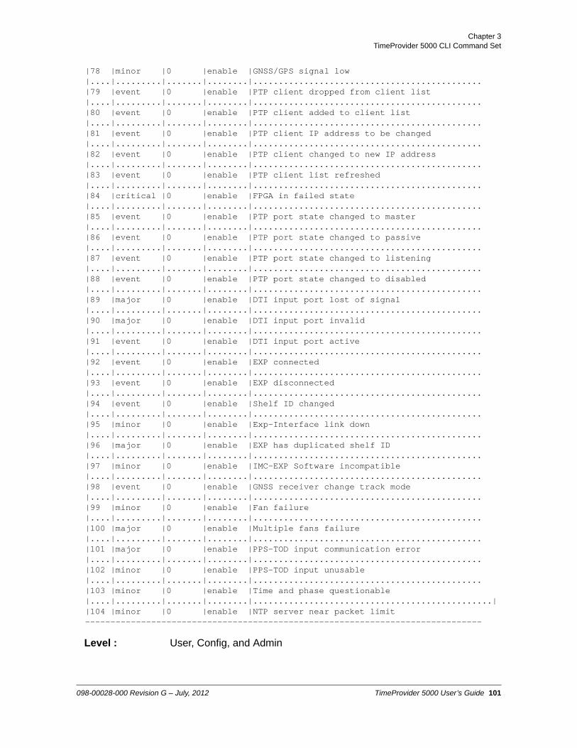
Chapter 3TimeProvider 5000 CLI Command Set
|78 |minor |0 |enable |GNSS/GPS signal low|....|.........|.......|........|.............................................|79 |event |0 |enable |PTP client dropped from client list|....|.........|.......|........|.............................................|80 |event |0 |enable |PTP client added to client list|....|.........|.......|........|.............................................|81 |event |0 |enable |PTP client IP address to be changed|....|.........|.......|........|.............................................|82 |event |0 |enable |PTP client changed to new IP address|....|.........|.......|........|.............................................|83 |event |0 |enable |PTP client list refreshed|....|.........|.......|........|.............................................|84 |critical |0 |enable |FPGA in failed state|....|.........|.......|........|.............................................|85 |event |0 |enable |PTP port state changed to master|....|.........|.......|........|.............................................|86 |event |0 |enable |PTP port state changed to passive|....|.........|.......|........|.............................................|87 |event |0 |enable |PTP port state changed to listening|....|.........|.......|........|.............................................|88 |event |0 |enable |PTP port state changed to disabled|....|.........|.......|........|.............................................|89 |major |0 |enable |DTI input port lost of signal|....|.........|.......|........|.............................................|90 |major |0 |enable |DTI input port invalid|....|.........|.......|........|.............................................|91 |event |0 |enable |DTI input port active|....|.........|.......|........|.............................................|92 |event |0 |enable |EXP connected|....|.........|.......|........|.............................................|93 |event |0 |enable |EXP disconnected|....|.........|.......|........|.............................................|94 |event |0 |enable |Shelf ID changed|....|.........|.......|........|.............................................|95 |minor |0 |enable |Exp-Interface link down|....|.........|.......|........|.............................................|96 |major |0 |enable |EXP has duplicated shelf ID|....|.........|.......|........|.............................................|97 |minor |0 |enable |IMC-EXP Software incompatible|....|.........|.......|........|.............................................|98 |event |0 |enable |GNSS receiver change track mode|....|.........|.......|........|.............................................|99 |minor |0 |enable |Fan failure|....|.........|.......|........|.............................................|100 |major |0 |enable |Multiple fans failure|....|.........|.......|........|.............................................|101 |major |0 |enable |PPS-TOD input communication error|....|.........|.......|........|.............................................|102 |minor |0 |enable |PPS-TOD input unusable|....|.........|.......|........|.............................................|103 |minor |0 |enable |Time and phase questionable|....|.........|.......|........|...............................................||104 |minor |0 |enable |NTP server near packet limit------------------------------------------------------------------------------
Level : User, Config, and Admin
098-00028-000 Revision G – July, 2012 TimeProvider 5000 User’s Guide 101

Chapter 3 TimeProvider 5000 CLI Command Set
set alarm-config
Provisions the alarm state, alarm level, and reporting delay time for the specified alarms.
Command Syntax:
To provision the state of the specified alarm number:
set alarm-config state {alarm [0 to max-alarm-id] | all} {enable | disable}
To provision the Level of the specified Alarm number:
set alarm-config level {alarm [0 to max-alarm-id] | all} {2 |3 | 4 | 5}
where:
2 - Critical3 - Major4 - Minor5 - Event
To provision the reporting delay of the specified Alarm number in seconds:
set alarm-config delay {alarm [0 to max-alarm-id] | all} [0 to 500000]
Range: Delay - 0 to 500,000 seconds
Default: Delay - 0 seconds
Example 1:
To Disable alarm #35
tp5000> set alarm-config state alarm 35 disable
Example 2:
To set the level of alarm #31 to Error - major (3)
tp5000> set alarm-config level alarm 31 3
Note: Use “show alarm-config” command to view the max-alarm-id of current TP5000 release.
102 TimeProvider 5000 User’s Guide 098-00028-000 Revision G – July, 2012

Chapter 3TimeProvider 5000 CLI Command Set
Remarks: The severity level and delay of transitory events cannot be changed.
Level : Config and Admin only
098-00028-000 Revision G – July, 2012 TimeProvider 5000 User’s Guide 103

Chapter 3 TimeProvider 5000 CLI Command Set
alias
This command is used to assign an alias for a CLI command (or any character string). The alias can then be used as a convenient substitution for the CLI command to which it has been assigned.
The alias command can also be used to display all defined aliases and the commands to which they have been assigned.
Command Syntax:
To assign an alias name to a command (or any portion of a command):
alias <user-defined-alias> “<character-string>”
To display all defined aliases and the commands to which they have been assigned:
alias
Example 1:
To set the alias “abc” for the command show ip status ioc. The command string must be contained within double quote marks (“”)
tp5000> alias abc “show ip status ioc”
Example 1a:
To use the alias “abc” to execute the command show ip status ioc
tp5000> abc
Response 1a:
ETH1 Link encap:Ethernet HWaddr 00:B0:AE:01:32:49
inet addr:192.168.1.11 Bcast:192.168.1.255 Mask:255.255.255.0
UP BROADCAST RUNNING MULTICAST MTU:1500 Metric:1
RX packets:0 errors:0 dropped:0 overruns:0 frame:0
TX packets:32 errors:0 dropped:0 overruns:0 carrier:0
collisions:0 txqueuelen:1000
RX bytes:0 (0.0 B) TX bytes:1920 (1.8 KiB)
ETH2 Link encap:Ethernet HWaddr 00:B0:AE:01:32:4A
inet addr:192.168.2.11 Bcast:192.168.2.255 Mask:255.255.255.0
104 TimeProvider 5000 User’s Guide 098-00028-000 Revision G – July, 2012

Chapter 3TimeProvider 5000 CLI Command Set
UP BROADCAST RUNNING MULTICAST MTU:1500 Metric:1
RX packets:6 errors:0 dropped:0 overruns:0 frame:0
TX packets:32 errors:0 dropped:0 overruns:0 carrier:0
collisions:0 txqueuelen:1000
RX bytes:360 (360.0 B) TX bytes:1920 (1.8 KiB)
Example 2:
To display the aliases assigned for the TP5000
tp5000> alias
Response 2:
alias show ip status ioc='ABC'
Level : User, Config, and Admin
098-00028-000 Revision G – July, 2012 TimeProvider 5000 User’s Guide 105

Chapter 3 TimeProvider 5000 CLI Command Set
show authentication
Displays how the system authenticates users.
If applicable, displays RADIUS server IP address or hostname and key.
Command Syntax:
show authentication
Example:
tp5000> show authentication
Response:
Authentication Info:
Radius server addr - 0.0.0.0Radius server key - 0Radius server port - 0
Radius server state - disable
Remarks: Authentication can be local or RADIUS
Level : Admin only
106 TimeProvider 5000 User’s Guide 098-00028-000 Revision G – July, 2012

Chapter 3TimeProvider 5000 CLI Command Set
set authentication
Provisions the authentication source for user logins. This command can also be used to change the port used for RADIUS authentication.
Command Syntax:
To provision the state for RADIUS authentication:
set authentication radius {enable | disable}
To provision the RADIUS server IP address or hostname and key and the port used for RADIUS authentication (optional).
set authentication radius address <ip_addr> key <key_value> [port <udp_port>]
Example 1:
To set the RADIUS server IP address 192.168.4.53, with a key of A12F34B56 (standard port 1812 is used):
tp5000> set authentication radius address 192.168.4.53 key A12F34B56
Example 2:
To provision the state for RADIUS authentication:
tp5000> set authentication radius enable
Example 3:
To change the RADIUS port to 1850 (port 1812 is standard) and to set the RADIUS server IP address 192.168.4.53, with a key of A12F34B56:
tp5000> set authentication radius address 192.168.4.53 key A12F34B56 port 1850
Remarks: Only one server is supported. Only one key is supported.
Level : Admin only
098-00028-000 Revision G – July, 2012 TimeProvider 5000 User’s Guide 107
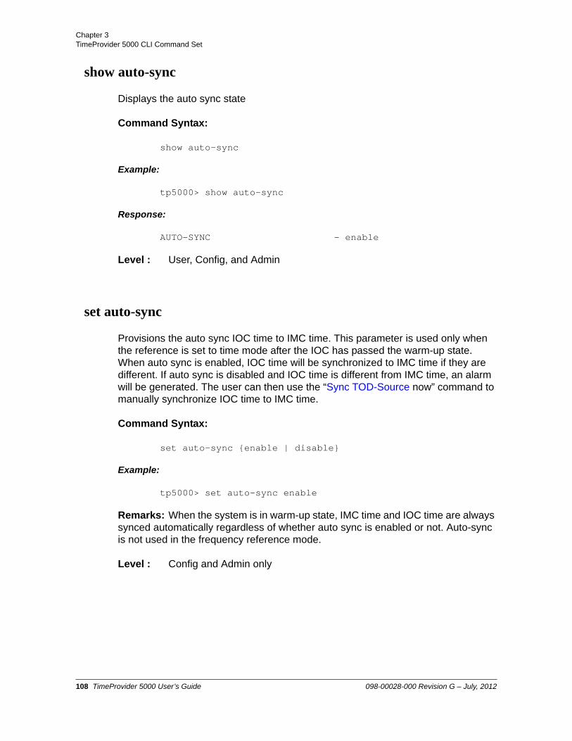
Chapter 3 TimeProvider 5000 CLI Command Set
show auto-sync
Displays the auto sync state
Command Syntax:
show auto-sync
Example:
tp5000> show auto-sync
Response:
AUTO-SYNC - enable
Level : User, Config, and Admin
set auto-sync
Provisions the auto sync IOC time to IMC time. This parameter is used only when the reference is set to time mode after the IOC has passed the warm-up state. When auto sync is enabled, IOC time will be synchronized to IMC time if they are different. If auto sync is disabled and IOC time is different from IMC time, an alarm will be generated. The user can then use the “Sync TOD-Source now” command to manually synchronize IOC time to IMC time.
Command Syntax:
set auto-sync {enable | disable}
Example:
tp5000> set auto-sync enable
Remarks: When the system is in warm-up state, IMC time and IOC time are always synced automatically regardless of whether auto sync is enabled or not. Auto-sync is not used in the frequency reference mode.
Level : Config and Admin only
108 TimeProvider 5000 User’s Guide 098-00028-000 Revision G – July, 2012

Chapter 3TimeProvider 5000 CLI Command Set
show bridge-time
Displays the bridging time that is used to allow the frequency servo to coast through short periods when the system does not have qualified reference. The bridging time is in seconds.
Command Syntax:
show bridge-time
Example:
tp5000> show bridge-time
Response:
Bridging Time - 900
Remarks: If the system has not qualified a ToD Source (frequency reference) within the specified bridging time the system transitions into holdover mode of operation.
Level : User, Config, and Admin
set bridge-time
Provisions the amount of time, in seconds, the system remains in bridging mode before transitioning into the holdover mode of operation.
Command Syntax:
set bridge-time <bridging-time>
Range: 100 to 100000 seconds
Default: 900 seconds
Example:
tp5000> set bridge-time 1000
Level : Config and Admin only
Note: Updates to the bridging-time value are only used at the start of the next bridging event. Any changes to this value while the unit is in bridging mode will not be implemented until the next bridging event.
098-00028-000 Revision G – July, 2012 TimeProvider 5000 User’s Guide 109

Chapter 3 TimeProvider 5000 CLI Command Set
show clock
Displays the date, time, and leapseconds in several formats.
– Current IMC time as a date and time
– Current IOC time as a date and time
– Accumulated leapseconds between TAI and UTC time
– Pending leapseconds
Command Syntax:
show clock
Example:
tp5000> show clock
Response 1:
IMC time: 2009-06-09 22:35:24IOC time: 2009-06-09 22:35:24Leap sec: 34Leap pend: 0
Response 2:
When the ToD source is GPS, and the system has never been locked to GPS, the response will be as follows:
IMC time: 2009-06-09 22:35:24 (not validated)IOC time: 2009-06-09 22:35:24 (not validated)Leap sec: 34Leap pend: 0
Level : User, Config, and Admin
set clock
Provisions the user-assigned Date, Time, and accumulated leapseconds. The reference mode must be set to the frequency mode with the set ref mode frequency command in order to change any clock settings.
Command Syntax:
To set the Date and Time
set clock date-time <date-time>
110 TimeProvider 5000 User’s Guide 098-00028-000 Revision G – July, 2012

Chapter 3TimeProvider 5000 CLI Command Set
To set the Accumulated leapseconds
set clock leapseconds <value>
Range: Accumulated leapseconds 20 to 255 seconds
Enter date and time in YYYY-MM-DD,HH:MM:SS format (UTC)
Example 1:
To set date to June 09 2009, and time to 10:35 PM and 24 sec.(UTC)
tp5000> set clock date-time 2009-06-09,22:35:24
tp5000> sync tod-source now
Example 2:
To set the accumulated leapseconds to 29 seconds
tp5000> set clock leapseconds 29
Remarks: The reference mode must be frequency in order to change date, time or leapseconds. If the reference mode is time, the user is not allowed to overwrite the date, time, or leapseconds. See Set REF command.
The “set clock” command only sets time on the IMC card. The "sync tod-source now" command must be sent after setting the time in order to sync IOC time to the IMC time.
Level : Config and Admin only
098-00028-000 Revision G – July, 2012 TimeProvider 5000 User’s Guide 111

Chapter 3 TimeProvider 5000 CLI Command Set
set configuration
Use this command to backup the current configuration, restore the current configuration from a backup copy, or set the current configuration to factory default values.
Command Syntax:
To set the current configuration, including imc, ioc and expansion shelves, to factory or default values
set configuration {default | factory}
– Default preserves user logins and communication attributes, such as ip addresses of MGMT port on IMC.
– Factory resets all attributes, including user logins.
To backup the current configuration
set configuration backup {imc-to-ioc | ioc-to-imc | local | exp[0-9]-to-IMC}
– Backup “imc-to-ioc” saves the configuration from the IMC module to both IOC modules.
– Backup “ioc-to-imc” saves the configuration from the active IOC module to the IMC module.
– Backup “local” saves the configuration to local non-volatile storage immediately.
– Backup “exp[0-9]-to-imc” saves the configuration for the specified expansion shelf to the IMC module.
To backup the current configuration from the IMC, active IOC, or expansion shelf to remote storage
set configuration backup remote {ioc | imc | exp[0-9]} <file name> [sftp:]<ip address> <user name>
After pressing Enter, the system prompts for the password
Password: <password>
To restore the current configuration:
set configuration restore {imc-from-ioc | ioc-from-imc | exp[0-9]-from-imc}
Note: For remote storage, path names should be specified as appropriate for the FTP/SFTP server and the operating system it is running on. This includes whether the entire path should be specified and whether "/" or "\" characters should be used.
112 TimeProvider 5000 User’s Guide 098-00028-000 Revision G – July, 2012

Chapter 3TimeProvider 5000 CLI Command Set
– Restore “ioc-from-imc” restores the IOC module configuration from the stored backup on the IMC module.
– Restore “imc-from-ioc” restores the IMC module configuration from the stored backup on the active IOC module.
– Restore “exp[0-9]-from-imc” restores the configuration for the specified expansion shelf from the stored backup on the IMC module.
To restore the current configuration from remote storage:
set configuration restore remote {ioc | imc | exp[0-9]} <file name> [sftp:]<ip address> <user name>
After pressing Enter, the system prompts for the password
Password: <password>
Example 1:
To set the configuration, including IMC, IOC and expansion shelves, to default values:
tp5000> set configuration default
Example 2:
To back up the configuration for both IOC modules to the IMC module:
tp5000> set configuration backup ioc-to-imc
Example 3:
To back up the system configuration data to local non-volatile storage:
tp5000> set configuration backup local
Example 4:
To restore the configuration for both IOC modules from the IMC module:
set configuration restore ioc-from-imc
Example 5:
Note: For remote storage, path names should be specified as appropriate for the FTP/SFTP server and the operating system it is running on. This includes whether the entire path should be specified and whether "/" or "\" characters should be used.
098-00028-000 Revision G – July, 2012 TimeProvider 5000 User’s Guide 113

Chapter 3 TimeProvider 5000 CLI Command Set
To back up the configuration data of IOC to a remote site, which is an SFTP server with the IP address of 172.16.33.33, id: tp5000, password: backup, with a file name for backup data of “tp5k_ioc_backup.txt”:
tp5000> set configuration backup remote ioc tp5k_ioc_backup.txt sftp:172.16.33.33 tp5000
Enter the password at the prompt and press Enter:
Password: backup
Example 6:
To restore the configuration data with a file name of tp5k_ioc_backup.txt for IOC from a remote site, which is an SFTP server with the IP address of 172.16.33.33, id: tp5000, password: backup:
tp5000> set configuration restore remote ioc tp5k_ioc_backup.txt sftp:172.16.33.33 tp5000
Enter the password at the prompt and press Enter:
Password: backup
Example 7:
To back up the configuration data for an expansion shelf with ID=6 to a remote site, which is an SFTP server with the IP address of 172.16.33.33, id: tp5000, password: backup, with a file name for backup data of “tp5k_exp6_backup.txt”:
tp5000> set configuration backup remote exp6 tp5k_exp6_backup.txt sftp:172.16.33.33 tp5000
Enter the password at the prompt and press Enter:
Note: For remote storage, path names should be specified as appropriate for the FTP/SFTP server and the operating system it is running on. This includes whether the entire path should be specified and whether "/" or "\" characters should be used.
Note: For remote storage, path names should be specified as appropriate for the FTP/SFTP server and the operating system it is running on. This includes whether the entire path should be specified and whether "/" or "\" characters should be used.
Note: For remote storage, path names should be specified as appropriate for the FTP/SFTP server and the operating system it is running on. This includes whether the entire path should be specified and whether "/" or "\" characters should be used.
114 TimeProvider 5000 User’s Guide 098-00028-000 Revision G – July, 2012

Chapter 3TimeProvider 5000 CLI Command Set
Password: backup
Example 8:
To restore the configuration data file tp5k_exp6_backup.txt back to an expansion shelf with ID=6 from the SFTP server with the IP address of 172.16.33.33, id: tp5000, password: backup:
tp5000> set configuration restore remote exp6 tp5k_exp6_backup.txt sftp:172.16.33.33 tp5000
Enter the password at the prompt and press Enter:
Password: backup
Remarks:
Setting the configuration to Default will not overwrite all user login information or current IP address of MGMT port on IMC. However, IP addresses for IOC will be set to default.
For remote storage, the configuration files should not be modified on the external storage device. If the configuration files are modified on the external storage device, TimeProvider 5000 will not import the revised configuration files.
When backing up configuration to an external storage device, user name and password settings are not included in the configuration file for security reasons. The user name and password are only backed up locally.
The following settings are unique to the unit and will not be backed up to an external storage device:
– Option and license keys
– Asset name
When restoring configuration files from the external storage device, the following settings are not restored:
– IMC IP mode and IP address setting
– IMC firewall setting
– Intra-system setting
The reason these settings are not restored is, if changed, the user could lose the management port connection to the TimeProvider 5000 system.
Note: For remote storage, path names should be specified as appropriate for the FTP/SFTP server and the operating system it is running on. This includes whether the entire path should be specified and whether "/" or "\" characters should be used.
098-00028-000 Revision G – July, 2012 TimeProvider 5000 User’s Guide 115

Chapter 3 TimeProvider 5000 CLI Command Set
The IOC module IP address is part of the configuration file. When restoring the IOC module configuration file to a different TimeProvider 5000, the user must set the IOC module IP address to avoid conflict with TimeProvider 5000 units that had the configuration file before being exported for backup. See the set ip command.
When restoring configuration files to a different TimeProvider 5000, the PTP Clock ID must be reinitialized back to its default setting. To re-initialize the PTP Clock ID use the following command:
tp5000> set ptp clockid ioc1-[x] ff:ff:ff:ff:ff:ff:ff:ff <enter>
Use SFTP when exporting or importing the IMC module and IOC module configuration files. SFTP is the same mechanism used for TimeProvider 5000 firmware downloads.
For remote storage, path names should be specified as appropriate for the FTP/SFTP server and the operating system it is running on. This includes whether the entire path should be specified and whether "/" or "\" characters should be used.
Level : Admin only
116 TimeProvider 5000 User’s Guide 098-00028-000 Revision G – July, 2012

Chapter 3TimeProvider 5000 CLI Command Set
show eia-232
This command displays the serial port’s operating parameters: baud rate, parity, word length, and stop bits.
Command Syntax:
show eia-232
Example:
tp5000> show eia-232
Response:
Baud rate- 57600Stop bit - 1Parity - 0Data length- 8Flow control- none
Remarks: The system's serial interface is fixed at 57.6K, 0, 8, 1; there is no handshaking. There is no associated Set command.
Level : User, Config, and Admin
098-00028-000 Revision G – July, 2012 TimeProvider 5000 User’s Guide 117

Chapter 3 TimeProvider 5000 CLI Command Set
set eth-auto-neg
The Set Ethernet Auto Negotiation command configures the Ethernet auto-negotiation feature for connection speed of the Ethernet ports on the IOC modules.
When Ethernet auto-negotiation is enabled, the TP5000 will advertise connection speeds of 100M, 1000M, or 100/1000M. The user can specify a connection speed for a port, 100 MB, 1000 MB, or All, to configure speed used by auto-negotiation. If auto negotiation is disabled, the Ethernet connection speed will be forced to 100M for Electrical SFPs and to 1000M for Optical SFPs
Command Syntax:
To set the state for Ethernet Auto Negotiation:
set eth-auto-neg state {ioc1-[y]|exp[0-9] {port [1-16] | all} {enable|disable}
To set the advertised speed for Ethernet Auto Negotiation:
set eth-auto-neg speed {ioc1-[y]|exp[0-9] {port [1-16] | all} {100m|1000m|all}
y=1 | 2, where y is the port number on the IOC
Defaults:
The default for auto-negotiation state is “enable”. The default value for auto-negotiation speed is “All”..
Example 1:
To set the advertised speed for Ethernet auto negotiation speed to “all” for Port 1 on IOC card 1
tp5000> set eth-auto-neg speed ioc1-1 all
Example 2:
To provision the Ethernet auto negotiation state for Port 1 on IOC card 1
tp5000> set eth-auto-neg state ioc1-1 enable
Example 3:
To set the advertised speed for Ethernet auto negotiation speed to "all" for Port 1 on
Note: See PTP / NTP Connections for information about optical and electrical SFPs.
118 TimeProvider 5000 User’s Guide 098-00028-000 Revision G – July, 2012

Chapter 3TimeProvider 5000 CLI Command Set
Exp shelf 9 (id=exp8)
tp5000> set eth-auto-neg speed exp8 port 1 all
Example 4:
To provision the Ethernet auto negotiation state for Port 3 on Exp shelf 8 (id=exp7)
tp5000> set eth-auto-neg state exp7 port 3 enable
Level : Config and Admin
098-00028-000 Revision G – July, 2012 TimeProvider 5000 User’s Guide 119

Chapter 3 TimeProvider 5000 CLI Command Set
show eth config
The Show Ethernet Configuration command displays the Ethernet auto-negotiation state and speed for the ports on the specified IOC module or expansion shelf.
Command Syntax:
show eth config {ioc1 | exp[0-9]}
Example 1:
To display the current configuration for the Ethernet ports on the IOC modules
tp5000> show eth config ioc1
Response 1:
eth1 auto-neg state: enableeth1 auto-neg speed: alleth2 auto-neg state: enableeth2 auto-neg speed: all
Example 2:
To display the current configuration for the Ethernet ports on expansion shelf ID=4
tp5000> show eth config exp4
Response 2:
120 TimeProvider 5000 User’s Guide 098-00028-000 Revision G – July, 2012

Chapter 3TimeProvider 5000 CLI Command Set
eth configuration information in expansion shelf ID=4:
Level : User, Config, and Admin
098-00028-000 Revision G – July, 2012 TimeProvider 5000 User’s Guide 121

Chapter 3 TimeProvider 5000 CLI Command Set
show eth-status
The Show Ethernet Status command displays the current speed for the Ethernet ports on all IOC modules or expansion shelf ports.
Command Syntax:
show eth-status {ioc | exp[0-9]}
Example 1:
To display the current speed for the Ethernet ports on the IOC modules
tp5000> show eth-status ioc
Response 1:
IOC1 eth1 current speed: noneIOC1 eth2 current speed: 100M
IOC2 eth1 current speed: 100MIOC2 eth2 current speed: none
Example 2:
To display the current speed for the Ethernet ports on expansion shelf 5 (id= 4)
tp5000> show eth-status exp4
Response 2:
Eth-status information in expansion shelf ID=4:
Level : User, Config, and Admin
122 TimeProvider 5000 User’s Guide 098-00028-000 Revision G – July, 2012

Chapter 3TimeProvider 5000 CLI Command Set
show event
This command displays the current events.
Command Syntax:
show event
Example:
tp5000> show event
Response:
-------------------------------------------------------------------|ID |Mod |Date-Time |Descriptions .......................||---|----|-------------------|------------------------------------||...|....|...................|....................................||27 |ioc1|2009-06-09 21:32:16|Entered normal-track mode ...........||...|....|...................|....................................||32 |ioc1|2009-06-09 20:54:19|GPS active .........................||...|....|...................|....................................||32 |ioc2|2009-06-09 20:53:31|GPS active .........................|-------------------------------------------------------------------
Level : User, Config, and Admin
098-00028-000 Revision G – July, 2012 TimeProvider 5000 User’s Guide 123

Chapter 3 TimeProvider 5000 CLI Command Set
show exp-if config
Use this command to display the configurations of DTI and Ethernet port on IMC and IO cards and expansion shelves.
Command Syntax:
show exp-if config {imc | io | exp[0-9]}
Example 1:
To display the
tp5000> show exp-if config imc
Response 1:
To display the configurations of DTI and Ethernet on the IMC expansion port
imc-exp eth state: enableimc-exp dti state: enable
Example 2:
To display the configurations of DTI and Ethernet on the IO expansion port
tp5000> show exp-if config io
Response 2:
io-exp-1 state: enableio-exp-2 state: enable
Example 3:
To display the configurations of DTI and Ethernet on expansion shelf 1 (id= 0) expansion port
tp5000> show exp-if config exp0
Response 3:
EXP-DTI in1 state : enableEXP-DTI in2 state : enable
Level : User, Config and Admin
124 TimeProvider 5000 User’s Guide 098-00028-000 Revision G – July, 2012

Chapter 3TimeProvider 5000 CLI Command Set
show exp-if status
Use this command to display the status of DTI and Ethernet expansion ports on IMC card, IO card (DTI only), and expansion shelves.
Command Syntax:
show exp-if status {imc | io | exp[0-9]}
Example 1:
To display the status of DTI and Ethernet on the IMC expansion port
tp5000> show exp-if status imc
Response 1a:
IMC-EXP DTI status : upIMC-EXP ETH status : up
Response 1b:
IMC-EXP DTI status : downIMC-EXP ETH status : down
Example 2:
To display the status of expansion ports on the IO card
tp5000> show exp-if status io
Response 2a:
io-exp-1: up io-exp-2: disabled
Response 2b:
io-exp-1: down io-exp-2: up
Example 3:
To display the status of DTI and Ethernet on expansion shelf ID=3 expansion port
tp5000> show exp-if status exp3
Response 3a:
098-00028-000 Revision G – July, 2012 TimeProvider 5000 User’s Guide 125
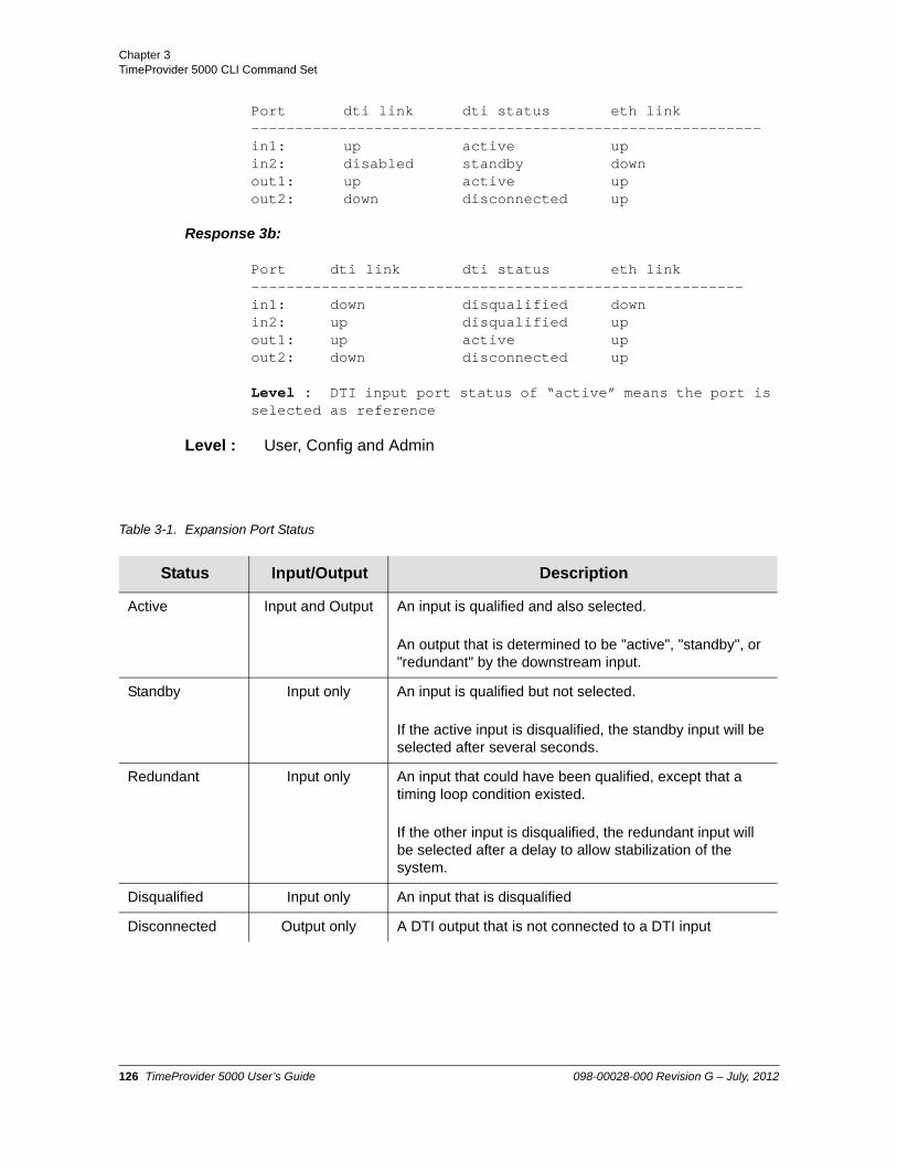
Chapter 3 TimeProvider 5000 CLI Command Set
Port dti link dti status eth link ----------------------------------------------------------in1: up active upin2: disabled standby downout1: up active upout2: down disconnected up
Response 3b:
Port dti link dti status eth link --------------------------------------------------------in1: down disqualified downin2: up disqualified upout1: up active upout2: down disconnected up
Level : DTI input port status of “active” means the port is selected as reference
Level : User, Config and Admin
Table 3-1. Expansion Port Status
Status Input/Output Description
Active Input and Output An input is qualified and also selected.
An output that is determined to be "active", "standby", or "redundant" by the downstream input.
Standby Input only An input is qualified but not selected.
If the active input is disqualified, the standby input will be selected after several seconds.
Redundant Input only An input that could have been qualified, except that a timing loop condition existed.
If the other input is disqualified, the redundant input will be selected after a delay to allow stabilization of the system.
Disqualified Input only An input that is disqualified
Disconnected Output only A DTI output that is not connected to a DTI input
126 TimeProvider 5000 User’s Guide 098-00028-000 Revision G – July, 2012

Chapter 3TimeProvider 5000 CLI Command Set
set exp-if dti
Use this command to enable or disable the DTI port between the IMC and expansion shelf, or the DTI ports in expansion shelf. that is used to connect to an expansion shelf. This command is typically used to disable the DTI port when there are no expansion shelves being used with the TP5000.
Command Syntax:
set exp-if dti {imc-exp | io-exp-1 | io-exp-2 | {exp[0-9] {in1|in2}}} {enable | disable}
Example 1:
To disable the DTI interface IN 1 port on expansion shelf ID=2 -
tp5000> set exp-if dti exp2 in1 disable
Example 2:
To enable the DTI interface port on the IMC card -
tp5000> set exp-if dti imc-exp enable
Example 3:
To enable the DTI interface port 1 on the IO card -
tp5000> set exp-if dti io-exp-1 enable
Remark : The imc-exp is the DTI port located on the IMC card. The dti-exp-1 and dti-exp-2 are the DTI ports located on the IO module. The exp[0-9] in1 and exp[0-9] in2 are the DTI IN 1 and DTI IN 2 ports located on the expansion shelves.
Level : Config, and Admin
098-00028-000 Revision G – July, 2012 TimeProvider 5000 User’s Guide 127

Chapter 3 TimeProvider 5000 CLI Command Set
set exp-if eth
Use this command to enable or disable the Ethernet port on the IMC that is used to connect to an expansion shelf. This command is typically used to disable the Ethernet port when there are no expansion shelves being used with the TP5000.
Command Syntax:
set exp-if eth imc-exp state {enable | disable}
Example:
To disable the Ethernet port on the exp-if interface on the IMC -
tp5000> set exp-if eth imc-exp state enable
Level : Config, and Admin
128 TimeProvider 5000 User’s Guide 098-00028-000 Revision G – July, 2012

Chapter 3TimeProvider 5000 CLI Command Set
show firewall
This command displays the firewall configuration.
Command Syntax:
show firewall
Example:
tp5000> show firewall
Response:
ICMP Firewall - allow TELNET Firewall - blockSSH Firewall - allowSFTP Firewall - allowSNMP Firewall - allowFTP Firewall - block
Level : User, Config and Admin
set firewall
Use this command to configure the system’s Ethernet port firewall. The firewall can control Telnet, SSH, FTP, SFTP, ICMP, and SNMP on the IMC.
Command Syntax:
set firewall imc telnet {allow|block}set firewall imc ssh {allow|block}set firewall imc ftp {allow|block}set firewall imc sftp {allow|block}set firewall imc snmp {allow|block}set firewall imc icmp {allow|block}
Example:
set firewall imc telnet allow
Remarks: Telnet and FTP are disabled by default on IMC. On IOC, all ports are blocked except ICMP and PTP. The IOC firewall configuration cannot be changed.
Level : Admin only
098-00028-000 Revision G – July, 2012 TimeProvider 5000 User’s Guide 129

Chapter 3 TimeProvider 5000 CLI Command Set
generate
This command generates all possible event and alarm messages. This command is for testing only.
Command Syntax:
generate message
Example:
tp5000> generate message
Response:
Level : Admin only
130 TimeProvider 5000 User’s Guide 098-00028-000 Revision G – July, 2012

Chapter 3TimeProvider 5000 CLI Command Set
show gnss
This command displays the GNSS port state, priority, position (latitude, longitude, height), elevation mask value (positioning filter), mode of operation (manual or automatic), and GPS or Beidou satellite tracking status. It also displays information for all satellite vehicles being tracked: vehicle number, health, noise ratio, satellite elevation, satellite azimuth.
Command Syntax:
To show the GPS configuration on the GNSS port -
show gnss config
To show the GPS status on the GNSS port -
show gnss status
Example 1:
tp5000>show gnss config
Response 1 :
State - enablePriority - 1Mode - autoGNSS Track-mode - gpsMask - 10Antenna Delay - 0PQL State - disablePQL Value - 1
GNSS manual position
Latitude - N37:22:42.900Longitude - W121:55:34.571Height - 15.4
Example 2:
tp5000>show gnss status
Response 2 :
Current Position Mode - manual
GNSS Status
Current Tracked-GNSS - GPS
098-00028-000 Revision G – July, 2012 TimeProvider 5000 User’s Guide 131

Chapter 3 TimeProvider 5000 CLI Command Set
Current Position Mode - manual
Latitude - N22:22:31.984Longitude - E11:12:21.996Height - 249.1
gps satellite status
----------------------------------------------------------
|Index |No. |SNR |Health |Azimuth |Elevation |
|------|----- |----- |---------- |---------- |--------- ||1 |3 |37 |healthy |313 |23 ||......|..... |..... |......... |.......... |......... ||2 |6 |38 |healthy |309 |35 ||......|..... |..... |......... |........ |......... ||3 |15 |43 |healthy |57 |31 ||......|..... |..... |......... |........ |......... ||4 |16 |39 |healthy |259 |24 ||......|..... |..... |......... |........ |......... ||5 |18 |39 |healthy |300 |82 ||......|..... |..... |......... |........ |......... ||6 |21 |42 |healthy |36 |67 ||......|..... |..... |......... |........ |......... ||7 |22 |42 |healthy |240 |47 ||......|..... |..... |......... |........ |......... ||8 |24 |42 |healthy |85 |29 ||......|..... |..... |......... |........ |......... ||9 |26 |38 |healthy |42 |18 ||......|..... |..... |......... |........ |......... ||10 |29 |42 |healthy |150 |26 ||------|----- |----- |---------- |--------- |--------- |
Beidou satellite status
--------------------------------------------------------|Index |No. |SNR |Health |Azimuth |Elevation ||......|..... |..... |......... |.......... |.......... ||1 |3 |37 |healthy |313 |23 ||......|..... |..... |......... |.......... |.......... ||2 |6 |38 |healthy |309 |35 ||......|..... |..... |......... |.......... |.......... ||3 |15 |43 |healthy |57 |31 |--------------------------------------------------------
132 TimeProvider 5000 User’s Guide 098-00028-000 Revision G – July, 2012

Chapter 3TimeProvider 5000 CLI Command Set
set gnss
Use this command to configure the GNSS port state, priority, positioning mode, mask, track mode, PQL state, and PQL value. Possible track modes for the GNSS port are:
forced GPS
forced Beidou
GPS priority over Beidou, switch automatically
Beidou priority over GPS, switch automatically
Command Syntax:
To change GNSS mode on the GNSS port:
set gnss mode { auto | manual [latitude <lat-value> longitude <lon-value> height<height-value>]}
– Position can only be provisioned manually when GNSS mode is “manual”.
Where
Latitude is in the format N|Sddd:mm:ss.sss, for example:N37:22:45.123S48:33:67.456
Longitude is in the format E|Wddd:mm:ss.sss, for example:W121:55:36.123E157:33:47.456
Height is in meters with one digit after the decimal point, for example:17.5
To change GNSS track mode on the GNSS port:
set gnss track-mode { beidou | gps | priority_beidou | priority_gps}
To enable or disable GNSS on the GNSS port:
set gnss state {enable|disable}
To set the priority on the GNSS port
set gnss priority <priority-value>
To set the GNSS mask value
Note: Symmetricom recommends that the Auto mode be used. Any error in the manually-specified system position will generate timing errors.
098-00028-000 Revision G – July, 2012 TimeProvider 5000 User’s Guide 133

Chapter 3 TimeProvider 5000 CLI Command Set
set gnss mask <mask-value>
To set the GNSS cable-delay value
set gnss cable-delay <delay-value>
To set the forced PQL state for the GNSS port
set gnss pql-state {enable | disable}
To set the forced PQL value for the GNSS port
set gnss pql-value <pql-value>
Range: Height: -999.9 to 18000.0 metersMask: 5 to 45 degreesCable Delay: 0 to 65485 nanosecondsPriority: 1 to 16, where 1 is highest priority and 16 is lowestPQL Value: 1 to 3
Default: Mask: 10 degreesCable Delay: 0 nanosecondsPQL State: DisablePQL Value: 1
Example 1:
To set GNSS to auto mode
tp5000>set gnss mode auto
Example 2:
To manually set the GNSS to manual mode, with a system position of latitude of N37:22:45.123, longitude of W121:55:36.123, and a height 17.5 meters
tp5000>set gnss mode manual latitude N37:22:45.123 longitude W121:55:36.123 height 17.5
Example 3:
To enable GNSS on the GNSS port
tp5000>set gnss state enable
Example 4:
To set GNSS priority on the GNSS port to a value of 3
tp5000>set gnss priority 3
134 TimeProvider 5000 User’s Guide 098-00028-000 Revision G – July, 2012

Chapter 3TimeProvider 5000 CLI Command Set
Example 5:
To set the GNSS mask to a value of 25 degrees
tp5000>set gnss mask 25
Example 6:
To set the GNSS cable delay to a value of 220 nanoseconds
tp5000>set gnss cable-delay 220
Restrictions: The system must have the GNSS mode of operation provisioned as manual before you can successfully provision the position manually.
Level : Config and Admin only
098-00028-000 Revision G – July, 2012 TimeProvider 5000 User’s Guide 135

Chapter 3 TimeProvider 5000 CLI Command Set
show gps
This command displays the position (latitude, longitude, height), elevation mask value (positioning filter), mode of operation (manual or automatic), and GPS satellite tracking status. It also displays information for all satellite vehicles being tracked: vehicle number, health, noise ratio, satellite elevation, satellite azimuth.
Command Syntax:
To display the GPS configuration on the GPS port:
show gps config
To display the GPS status on the GPS port:
show gps status
Example 1:
tp5000>show GPS config
Response 1:
GPS Configuration
State - enablePriority - 2Mode - autoMask - 10Antenna Delay - 0PQL State - disablePQL Value - 1
GPS manual position
Latitude - N37:22:43.425Longitude - W121:55:34.815Height - 13.7
Example 2:
tp5000>show gps status
Response 2:
GPS Status
136 TimeProvider 5000 User’s Guide 098-00028-000 Revision G – July, 2012

Chapter 3TimeProvider 5000 CLI Command Set
Current Position Mode - position holdLatitude - N37:22:42.867Longitude - W121:55:34.552Height - 17.3
GPS Satellites Status
----------------------------------------------------------|Index |No. |SNR |Health |Azimuth |Elevation||------|---------|---------|---------|---------|---------||1 |3 |37 |healthy |313 |23 ||......|.........|.........|.........|.........|.........||2 |6 |38 |healthy |309 |35 ||......|.........|.........|.........|.........|.........||3 |15 |43 |healthy |57 |31 ||......|.........|.........|.........|.........|.........||4 |16 |39 |healthy |259 |24 ||......|.........|.........|.........|.........|.........||5 |18 |39 |healthy |300 |82 ||......|.........|.........|.........|.........|.........||6 |21 |42 |healthy |36 |67 ||......|.........|.........|.........|.........|.........||7 |22 |42 |healthy |240 |47 ||......|.........|.........|.........|.........|.........||8 |24 |42 |healthy |85 |29 ||......|.........|.........|.........|.........|.........||9 |26 |38 |healthy |42 |18 ||......|.........|.........|.........|.........|.........||10 |29 |42 |healthy |150 |26 |----------------------------------------------------------
Level : User, Config, and Admin
098-00028-000 Revision G – July, 2012 TimeProvider 5000 User’s Guide 137

Chapter 3 TimeProvider 5000 CLI Command Set
set gps
Use this command to provision the GPS port for mode of operation, position, and positioning elevation mask. With this command, you can provision the GPS to use either automatic or manual mode to determine the system’s position. You can provision the GPS position if the system is provisioned for Manual mode of operation. You can also provision the elevation mask to provide a method of filtering satellites to be used by the system.
Command Syntax:
To set the GPS mode
set gps mode {auto|manual} [latitude <lat-value> longitude <lon-value> height<height-value>]
– Position can only be provisioned manually when GPS mode is “manual”.
Where
Latitude is in the format N|Sddd:mm:ss.sss, for example:N37:22:45.123S48:33:67.456
Longitude is in the format E|Wddd:mm:ss.sss, for example:W121:55:36.123E157:33:47.456
Height is in meters with one digit after the decimal point, for example:17.5
To enable or disable GPS
set gps state {enable|disable}
To set the GPS priority
set gps priority <priority-value>
To set the GPS mask value
Note: Latitude and Longitude are entered as pddd:mm:ss.sss, where p is N or S for latitude and E or W for longitude, ddd is degrees, mm is minutes, and ss.sss is seconds. For example: N59:20:3.458 or W121:31:42.69. Height is in meters, with a range of -999.9 to 40000.0 meters
Note: Symmetricom recommends that the Auto mode be used. Any error in the manually-specified system position will generate timing errors.
138 TimeProvider 5000 User’s Guide 098-00028-000 Revision G – July, 2012

Chapter 3TimeProvider 5000 CLI Command Set
set gps mask <mask-value>
To set the GPS cable-delay value
set gps cable-delay <delay-value>
To set the forced PQL state for the GPS port
set gps pql-state {enable | disable}
To set the forced PQL value for the GPS port
set gps pql-value <pql-value>
Range: Height: -999.9 to 40000.0 metersMask: 5 to 45 degreesCable Delay: 0 to 999999 nanosecondsPriority: 1 to 16, where 1 is highest priority and 16 is lowestPQL-Value: 1 to 3
Default: Mask: 10 degreesCable Delay: 0 nanoseconds
Example 1:
To set GPS to auto mode
tp5000>set GPS mode auto
Example 2:
To manually set the GPS to manual mode, with a system position of latitude of N37:22:45.123, longitude of W121:55:36.123, and a height 17.5 meters
tp5000>set GPS mode manual latitude N37:22:45.123 longitude W121:55:36.123 height 17.5
Example 3:
To enable GPS
tp5000>set gps state enable
Example 4:
To set GPS priority to a value of 2
tp5000>set gps priority 2
Example 3:
098-00028-000 Revision G – July, 2012 TimeProvider 5000 User’s Guide 139

Chapter 3 TimeProvider 5000 CLI Command Set
To set the GPS mask to a value of 25 degrees
tp5000>set GPS mask 25
Example 4:
To set the GPS cable delay to a value of 220 nanoseconds
tp5000>set GPS cable-delay 220
Restrictions: The system must have the GPS mode of operation provisioned as manual before you can successfully provision the position manually.
Level : Config and Admin only
140 TimeProvider 5000 User’s Guide 098-00028-000 Revision G – July, 2012

Chapter 3TimeProvider 5000 CLI Command Set
show hardware-status
This command displays the status of the specified hardware.
Command Syntax:
show hardware-status {imc | ioc1 | ioc2 | exp[0-9]}
Example 1:
To show the hardware status for IMC card
tp5000> show hardware-status imc
Response 1:
-48V-A : ok-48V-B : ok+1.2V : 1.211V+1.8V : 1.843V+2.5V : 2.526V+5.5V : 5.490VVCXO : 2.526VGPS Power : 5.464VGPS Current : 24mAGPS Antenna : okFPGA : ok
Example 2:
To show the hardware status for IOC1
tp5000> show hardware-status ioc1
Response 2:
+1.8V : 1.805V10M EFC : 1.116V20M EFC : 0.872V25M EFC : 1.155V24.5M EFC : 1.155V24.7M EFC : 1.253VOSC Current : 173mAFPGA VCCint : 1.005VFPGA VCCaux : 2.499VFPGA Temp : 60CFPGA Temp High : 61CFPGA Temp Low : 54C
Example 3:
To show the hardware status for PTP/SyncE expansion shelf ID=3
098-00028-000 Revision G – July, 2012 TimeProvider 5000 User’s Guide 141

Chapter 3 TimeProvider 5000 CLI Command Set
tp5000> show hardware-status exp3
Response 3:
-48V-A : failed-48V-B : okVCXO : 1.701V12V : 11.807V1.8V : 1.778V2.5V : 2.487V1.2V : 1.173V0.9V : 0.889V1.0V : 0.992VF1.1V : 1.082VF1.5V : 1.482VF2.5V : 2.101VG1.1V : 1.082VG1.5V : 1.482VG2.5V : 2.462VFPGA : okTemp : 35CTemp High : 41CTemp Low : 35C
Level : User, Config, and Admin
142 TimeProvider 5000 User’s Guide 098-00028-000 Revision G – July, 2012

Chapter 3TimeProvider 5000 CLI Command Set
history
This command shows the command history for the current session.
Command Syntax:
history
Example:
tp5000> history
Response:
0 2009-06-10 00:11:28 show eth-status1 2009-06-10 00:12:24 show event2 2009-06-10 00:13:15 show firewall3 2009-06-10 00:16:02 set firewall imc sftp4 2009-06-10 00:16:31 generate message5 2009-06-10 00:17:07 show gps6 2009-06-10 00:19:59 set gps mode auto7 2009-06-10 00:21:49 set gps mask 108 2009-06-10 00:22:40 set gps cable-delay 19 2009-06-10 00:22:48 set gps cable-delay 010 2009-06-10 00:23:47 show hardware-status imc11 2009-06-10 00:24:14 show hardware-status ioc112 2009-06-10 00:25:19 history
Level : User, Config, and Admin
098-00028-000 Revision G – July, 2012 TimeProvider 5000 User’s Guide 143

Chapter 3 TimeProvider 5000 CLI Command Set
show hostname
This command displays the host name for the TimeProvider 5000.
Command Syntax:
show hostname
Example:
tp5000> show hostname
Response
Host name - TP5000
Level : User, Config, and Admin
set hostname
This command sets the host name for the TimeProvider 5000. Hostname can contain up to 20 characters.
Command Syntax:
set hostname <hostname_string>
Example:
To set the hostname to “PTPhost3”
tp5000> set hostname PTPhost3
Level : Config and Admin only
Note: The hostname will be used for the SNMP sysName object. However, if sysName is changed via SNMP, SNMP will then use the updated value until the next restart of SNMP, but hostname will not be changed.
144 TimeProvider 5000 User’s Guide 098-00028-000 Revision G – July, 2012

Chapter 3TimeProvider 5000 CLI Command Set
show image
This command displays the firmware image used by each module in the system and the firmware version.
Command Syntax:
show image
Example:
tp5000> show image
Response:
IMC IMAGE DETAILS
Active image: 2 1.0.4_200811040901Backup image: 1 1.0.2_200810231325Next boot image: 2
IOC1 IMAGE DETAILS
Active image: 2 1.0.4_200811040858Backup image: 1 1.0.2_200810231322Next boot image: 2
IOC2 IMAGE DETAILS
Active image: 2 1.0.4_200811040858Backup image: 1 1.0.4_200811040858Next boot image: 2
Exp0 IMAGE DETAILS
Active image: 2 1.0.4_200811040901Backup image: 1 1.0.2_200810231325Next boot image: 2
Exp4 IMAGE DETAILS
Active image: 2 1.0.4_200811040901Backup image: 1 1.0.2_200810231325Next boot image: 2
. . .
Exp8 IMAGE DETAILS
Active image: 2 1.0.4_200811040901Backup image: 1 1.0.2_200810231325Next boot image: 2
098-00028-000 Revision G – July, 2012 TimeProvider 5000 User’s Guide 145

Chapter 3 TimeProvider 5000 CLI Command Set
Level : User, Config, and Admin
set image
Use this command to provision the module firmware image from which to boot. The backup image is the inactive (non-boot) image.
Command Syntax:
set image {imc|ioc1|ioc2|exp[0-9]}[1|2]
Example 1:
To set the IMC to boot image 1
tp5000> set image imc 1
Example 2:
To set expansion shelf 4 (id=3) to boot image 2
tp5000> set image exp3 2
Example 3:
To set IOC1 to boot image 2
tp5000> set image ioc1 2
Remark: The module must be rebooted to implement the boot image.
Level : Admin only
Note: Each image has it's own set of configuration data. If Image 1 is set as the boot image, the configuration data for Image 1 is applied when the TP 5000 is rebooted. If Image 2 is set as the boot image, the configuration data for Image 2 is applied when the TP 5000 is rebooted.
A firmware upgrade is applied to the backup image, and the backup image is set to be the next boot image. The TP 5000 copies the currently running configuration data to the data used with the next boot. Therefore, the configuration should be the same after rebooting, except for changes due to differences in supported configuration items between firmware revisions..
146 TimeProvider 5000 User’s Guide 098-00028-000 Revision G – July, 2012

Chapter 3TimeProvider 5000 CLI Command Set
show input-config
This command displays the input port's state, priority, framing type, CRC, SSM state, SSM Bit, user-assigned SSM PQL value and whether the configuration settings for the port are used. The settings will not be used if the port is configured as an output..
Command Syntax:
show input-config
Example:
tp5000> show input-config
Response:
------------------------------------------------------------------------------|Port ID| State |Prio|Frame Type |CRC St |SSM St |SSM Bit|PQL Val|Config Used||-------|-------|----|-----------|-------|-------|-------|-------|-----------|| port1 |disable| 1 |cas |disable|disable| 8 | 3 | no ||.......|.......|....|...........|.......|.......|.......|.......|...........|| port2 |disable| 2 |freq2048khz|disable|disable| 8 | 3 | yes ||.......|.......|....|...........|.......|.......|.......|.......|...........|
Note: See 'show io-status' for current port status and direction.
Level : User, Config, and Admin
set input
Use this command to provision the System's Input Port(s) for the following:
Priority
State
Framing Type
CRC state for E1 signals
Forced PQL state for port
PQL Bit position for E1/T1 signals
Forced PQL-value (this value is used if SSM is disabled)
Note: Setting the Time of Day source to GPS with the set tod-source command will also set the input reference port state to Disable.
098-00028-000 Revision G – July, 2012 TimeProvider 5000 User’s Guide 147

Chapter 3 TimeProvider 5000 CLI Command Set
Priority Quality Level (PQL) values are listed in the following table.
Command Syntax:
To set the priority for the specified input port:
set input priority port[1|2] [1-16]
To provision the state for the specified input port:
set input state port[1|2] [enable|disable]
To set the frame type for the specified input port:
Quality Level DS1 SSM E1 SSM Description
1 0x04 0x02 Stratum 1/PRS/PRC
2 0x08 0x00 STU, Stratum Unknown (presumed ST1)
3 0x0C 0x04 Stratum 2/Type II
4 0x0C 0x04 Type I
5 0x78 0x04 Transit Node/Type V
6 0x7C 0x08 Type III/Stratum 3E
7 0x10 0x0B Type IV/Stratum 3
8 0x22 0x0F G.813OPT2/SMC
9 0x30 0x0F DUS, Do not Use for Sync
15 --- --- Did not receive valid SSM
Note: Enabling the input state for a programmable I/O port with the “set input state” command will also set that port as an input port and set the output state for that port to Disable.
Enabling the output state for a programmable I/O port with the “Set Output state” command will also set that port as an output port and set the input state for that port to Disable.
Note: Setting the Time of Day source to GPS with the set tod-source command will also set the input reference port state to Disable.
148 TimeProvider 5000 User’s Guide 098-00028-000 Revision G – July, 2012

Chapter 3TimeProvider 5000 CLI Command Set
set input frametype port[1|2] [d4|esf|ccs|cas|freq2048khz|freq1544khz]
To provision the CRC state for the specified input port:
set input crc port[1|2] [enable|disable]
To provision the SSM state for the specified input port:
set input ssm port[1|2] [enable|disable]
To provision the SSM Bit position for E1 signals for the specified input port (used only for ESF, CCS or CAS framing type):
set input ssm-bit port[1|2] [4|5|6|7|8]
To set the forced PQL value for the specified input port:
set input pql-value port[1|2] <pql-value>
where pql-value is from 1 to 9
Example 1:
To set the priority to 1 for input port 2:
tp5000> set input priority port2 1
Example 2:
To provision the state to Enable for input port 1:
tp5000> set input state port1 enable
Note: The default input frame type is freq2048khz.
Note: Synchronization Status Message (SSM) is only supported for the frametypes ESF, CAS with CRC4 and CCS with CRC4. SSM should not be enabled for other input frame types.
If SSM is enabled for an input port and the frametype does not support SSM or is not sending a valid SSM, then the input will be disqualified and the input SSM will be set to 15 (invalid). The system will go to holdover if there is not another qualified reference to switch to.
Note: Enabling the input state for a programmable I/O port with the “set input state” command will also set that port as an input port and set the output state for that port to Disable.
098-00028-000 Revision G – July, 2012 TimeProvider 5000 User’s Guide 149

Chapter 3 TimeProvider 5000 CLI Command Set
Example 3:
To set the frame type to 2048 kHz for input port1:
tp5000> set input frametype port1 freq2048khz
Example 4:
To provision the CRC state to Enable for input port2:
tp5000> set input crc port2 enable
Example 5:
To provision the forced PQL state to Disable for input port1:
tp5000> set input pql-state port1 disable
Example 6:
To provision the SSM PQL Bit value for E1 signals to 6 for input port2:
tp5000> set input ssm-bit port2 6
Example 7:
To set the SSM PQL value to 3 (Stratum 2/Type II) for input port1:
tp5000> set input pql-value port1 3
Level : Config and Admin only
150 TimeProvider 5000 User’s Guide 098-00028-000 Revision G – July, 2012

Chapter 3TimeProvider 5000 CLI Command Set
show intra-system
Use this command to display which Class of network and IP addresses are used for IMC-to-IOC and IOC-to-IOC communications.
Command Syntax:
show intra-system
Example:
tp5000> show intra-system
Response:
Intra-communication IP set - setB
Level : Config and Admin only
set intra-system
Use this command to provision which Class of network and IP addresses are used for IMC-to-IOC and IOC-to-IOC communications.
Command Syntax:
set intra-system [a|b|c]
where
A: IP address range 10.0.250.8 to 10.0.250.63B: IP address range 172.16.250.8 to 172.16.250.63C: IP address range 192.168.250.8 to 192.168.250.63
Example:
To set the intra-system IP addresses to range 3 for IMC-to-IOC and IOC-to-IOC communications
tp5000> set intra-system c
Remarks: These addresses can't be used for external Ethernet ports.
Level : Config and Admin only
098-00028-000 Revision G – July, 2012 TimeProvider 5000 User’s Guide 151

Chapter 3 TimeProvider 5000 CLI Command Set
show inventory
This command displays the installed module inventory information as follows:
model number
user-assigned asset number
IMC and IOC module part numbers
IMC and IOC module CLEI numbers
IMC and IOC module serial numbers
IMC and IOC module hardware versions
IMC and IOC module FPGA versions
IMC and IOC module compatibility mask
IMC and IOC module firmware versions
Exp shelf part number
Exp shelf CLEI number
Exp shelf serial number
Exp shelf hardware version
Exp shelf FPGA version (clock FPGA)
Exp shelf compatibility mask
Exp shelf firmware version
The compatibility information allows the user to verify the compatibility between the hardware and software for each card. To be compatible, the hex numerical string displayed for the hardware (HW) of a card must match the numerical string displayed for the software (SW) of that card. See Figure 3-2.These hex numerical strings are generated from a compatibility algorithm.
For IMC-to-IOC compatibility, the numerical strings for the IMC and IOC cards must match. See Figure 3-2. For IOC-to-IOC compatibility, the numerical strings for the IOC cards must match.
Figure 3-2. Checking HW / SW and Card-to-Card Compatibility
152 TimeProvider 5000 User’s Guide 098-00028-000 Revision G – July, 2012

Chapter 3TimeProvider 5000 CLI Command Set
Command Syntax:
show inventory
Example:
tp5000> show inventory
Response:
General Inventory Info:
System Model - TimeProvider 5000
Chassis Type - front-access(090-50301-01)
I/O Module Type - 2-port E1 plus TOD input I/O module(090-50315-01)
Asset Number - 19
Module Inventory Info:
------------------------------------------------------------------------------
|Mod |Slot |Part Num |CLEI Num |Serial |HW Ver |FPGA |SW Version|
|----|------|----------------|-----------|--------|-------|-------|----------|
|imc |middle|090-50331-02 |unknown |R75541 |unknown|0x1E |2.0.4 |
|....|......|................|...........|........|.......|.......|..........|
|ioc1|left |090-50321-01 |unknown |R74829 |B/D |0x5B |0.0.261 |
------------------------------------------------------------------------------
Compatibility Info:
--------------------------------------------------------------------------
|Mod |HW Compatibility|SW Compatibility|IMC-IOC Compati.|IOC-IOC Compati.|
|----|----------------|----------------|----------------|----------------|
|imc |0x00000000 |0x00000000 |0x00000006 |n/a |
|....|................|................|................|................|
098-00028-000 Revision G – July, 2012 TimeProvider 5000 User’s Guide 153

Chapter 3 TimeProvider 5000 CLI Command Set
|ioc1|0x00000000 |0x00000000 |0x00000006 |0x00000007 |
--------------------------------------------------------------------------
---------------------------------------------------------
|Mod |HW Compatibility|SW Compatibility|IMC-EXP Compati.|
|----|----------------|----------------|----------------|
|imc |0x00000000 |0x00000000 |0x00000003 |
---------------------------------------------------------
Remarks: Only the asset number can be modified.
Level : User, Config, and Admin
set inventory
Use this command to provision the system's user-assigned asset value information.
Command Syntax:
set inventory asset <asset-value>
Range: Enter user-assigned asset value from 1 to 20 characters.
Example:
To set the inventory asset to a value of “tcb121”
tp5000> set inventory asset tcb121
Level : Config and Admin only
154 TimeProvider 5000 User’s Guide 098-00028-000 Revision G – July, 2012

Chapter 3TimeProvider 5000 CLI Command Set
set io
This command provisions the system's I/O module port configuration.
Command Syntax:
set io port[1|2] {input | output}
Example 1:
To set Port 1 of the I/O module as an Input
tp5000> set io port1 input
Example 2:
To set Port 2 of the I/O module as an Output
tp5000> set io port2 output
Related : show io-status,
Level : Config, and Admin
Note: The “set io” command is related to the “set input” and “set output” commands. Setting the io to input will set the output state to Disable. Setting the io to output will set the input state to Disable.
Enabling the input state for a programmable I/O port with the “set input state” command will also set that port as an input port and set the output state for that port to Disable.
Enabling the output state for a programmable I/O port with the “Set Output state” command will also set that port as an output port and set the input state for that port to Disable.
098-00028-000 Revision G – July, 2012 TimeProvider 5000 User’s Guide 155

Chapter 3 TimeProvider 5000 CLI Command Set
show ioc-state
This command displays the state of both the active and standby IOC module. If either IOC module cannot assume the active or standby state, the state indicates NOT AVAILABLE.
Command Syntax:
show ioc-state
Example:
tp5000> show ioc-state
Response:
---------------------------------|Module ID |State ||---------------|---------------||ioc1 |active ||...............|...............||ioc2 |standby |---------------------------------
Level : User, Config, and Admin
set ioc-state
Use this command to provision the standby module to become the active module. IOC1 refers the IOC module to the left of the IMC and IOC2 refers to the IOC module to the right of the IMC.
Command Syntax:
set ioc-state {ioc1 | ioc2} active
Example:
tp5000> set ioc-state ioc2 active
Remarks :
Switchover to the standby IOC will be prohibited if the standby IOC has alarms of higher severity than the active IOC, or if the standby IOC is still in warm-up. Check system status and alarms if the command fails.
Level : Config and Admin only
156 TimeProvider 5000 User’s Guide 098-00028-000 Revision G – July, 2012

Chapter 3TimeProvider 5000 CLI Command Set
show io-status
This command displays the system's I/O module port configuration and status. It also displays the current SSM value for both inputs and outputs. The current SSM value is displayed for all outputs, even if SSM is not applicable for that type of output. If the current SSM is unknown, due to an unknown SSM code or inappropriate frametype, then an SSM value of 15 will be displayed.
Command Syntax:
show io-status
Example:
tp5000> show io-status
Response:
------------------------------------------------------------------|Port ID | I/O Type | Signal Type | Current Status | Current SSM ||--------|----------|-------------|----------------|-------------|| port1 | Output |T1pulse | ON | 1 ||........|..........|.............|................|.............|| port2 | Input |E1/2.048MHz | OFF | 15 ||........|..........|.............|................|.............|| port3 | Output |1PPS | ON | 15 ||........|..........|.............|................|.............|| port4 | Output |10MHz | ON | 15 ||........|..........|.............|................|.............|
Note: See 'show input-config' or 'show output-config' for port configuration.
Level : User, Config, and Admin
098-00028-000 Revision G – July, 2012 TimeProvider 5000 User’s Guide 157

Chapter 3 TimeProvider 5000 CLI Command Set
show ip
This command displays the Host, Mask, and Gateway IP addresses for Ethernet interfaces on the specified module. It also indicates if DHCP is enabled and if the port is enabled.
Command Syntax:
To show the configuration of the Ethernet interfaces for the specified module (some settings will only be implemented after restarting the IP interface):
show ip config {imc | ioc1 | exp[0-9]}
To show the current status of the Ethernet interfaces for the specified module:
show ip status {imc | ioc1 | exp[0-9]} [vlan-id <vlan>]
Defaults:
See Table B-21 for default IP address for the IMC module.See Table B-27 for default IP address for IOC1 and IOC2 modules.
Example 1:
To display the configuration of the Ethernet interfaces for the IMC module
tp5000> show ip config imc
Response 1:
MGMT PORT PARAMETERS
IP mode : dhcpIP state : enable
Example 2:
To display the configuration of the Ethernet interfaces for the IOC1 module
tp5000> show ip config ioc1
Response 2:
ETH1 PORT PARAMETERS
Note: Packet and byte counts do not include most PTP and NTP packets.
158 TimeProvider 5000 User’s Guide 098-00028-000 Revision G – July, 2012

Chapter 3TimeProvider 5000 CLI Command Set
IP address: 192.168.1.11IP mask : 255.255.255.0IP gateway: 0.0.0.0IP state : enable
ETH2 PORT PARAMETERS
IP address: 192.168.2.11IP mask : 255.255.255.0IP gateway: 0.0.0.0IP state : enable
Example 3:
To display the status of the Ethernet interfaces for the IMC module
tp5000> show ip status imc
Response 3:
MGMT Link encap:Ethernet HWaddr 00:B0:AE:00:00:05
inet addr:192.168.5.14 Bcast:192.168.5.255 Mask:255.255.255.0
UP BROADCAST RUNNING MULTICAST MTU:1500 Metric:1
RX packets:70867 errors:0 dropped:0 overruns:0 frame:0
TX packets:1986 errors:0 dropped:0 overruns:0 carrier:0
collisions:0 txqueuelen:1000
RX bytes:4511319 (4.3 MiB) TX bytes:162895 (159.0 KiB)
Interrupt:21 Base address:0xe000
Example 4:
To display the status of the Ethernet interfaces for the IOC module
tp5000> show ip status ioc
Response 4:
ETH1 Link encap:Ethernet HWaddr 00:B0:AE:01:32:49
inet addr:192.168.1.11 Bcast:192.168.1.255 Mask:255.255.255.0
UP BROADCAST RUNNING MULTICAST MTU:1500 Metric:1
RX packets:0 errors:0 dropped:0 overruns:0 frame:0
TX packets:32 errors:0 dropped:0 overruns:0 carrier:0
098-00028-000 Revision G – July, 2012 TimeProvider 5000 User’s Guide 159

Chapter 3 TimeProvider 5000 CLI Command Set
collisions:0 txqueuelen:1000
RX bytes:0 (0.0 B) TX bytes:1920 (1.8 KiB)
ETH2 Link encap:Ethernet HWaddr 00:B0:AE:01:32:4A
inet addr:192.168.2.11 Bcast:192.168.2.255 Mask:255.255.255.0
UP BROADCAST RUNNING MULTICAST MTU:1500 Metric:1
RX packets:6 errors:0 dropped:0 overruns:0 frame:0
TX packets:32 errors:0 dropped:0 overruns:0 carrier:0
collisions:0 txqueuelen:1000
RX bytes:360 (360.0 B) TX bytes:1920 (1.8 KiB)
Level : User, Config, and Admin
set ip
Use this command to provision the Host, Mask, and Gateway IP addresses for IMC and IOC Ethernet interfaces.
The special value of 0.0.0.0 should be used for the gateway value if a gateway router is not required.
Command Syntax:
To provision the state of the Ethernet interfaces for the specified module and port:
set ip {imc|ioc1-1|ioc1-2|exp[0-9] port<1-16>} [enable|disable|restart]
To set the address, mask and gateway of the Ethernet interfaces for the specified module and port:
Note: To configure a VLAN, use the command set vlan to provision the IP addresses.
160 TimeProvider 5000 User’s Guide 098-00028-000 Revision G – July, 2012

Chapter 3TimeProvider 5000 CLI Command Set
set ip (imc|ioc1-1|ioc1-2|exp[0-9] port<1-16>} address <addr_value> netmask <mask_value> gateway <gateway value>
Example 1:
To restart the IMC module Ethernet interface:
tp5000> set ip imc restart
Example 2:
To Enable the IP interface for Port 2 of the active card:
tp5000> set ip ioc1-2 enable
Example 3:
To set the IP address for the IMC module to 192.168.2.11, the mask to 255.255.255.0, and the gateway 192.168.2.1:
tp5000> set ip imc address 192.168.2.11 mask 255.255.255.0 gateway 192.168.2.1
tp5000> set ip imc restart
Example 4:
To set the IP address for Port 2 on the IOC card to 192.168.2.3, the mask to 255.255.255.0, and the gateway 192.168.2.1:
tp5000> set ip ioc1-2 address 192.168.2.3 mask 255.255.255.0 gateway 192.168.2.1
tp5000> set ip ioc1-2 restart
Example 5:
To set the IP address for Port 2 on expansion shelf 4 (id: exp3) to 192.168.2.3, the mask to 255.255.255.0, and no gateway:
tp5000> set ip exp3 port 2 address 192.168.2.3 mask 255.255.255.0 gateway 0.0.0.0
tp5000> set ip exp3 port 2 restart
Note: In order for the configuration change to take affect, the interface must be restarted with the "set ip {imc|ioc1-1|ioc1-2|exp[0-9] port<1-16>} restart" command.
098-00028-000 Revision G – July, 2012 TimeProvider 5000 User’s Guide 161

Chapter 3 TimeProvider 5000 CLI Command Set
Remarks: The address format allows IPv4 multiple octet formats. Restart the interface after configuring the system in order to implement the new settings.
Level : Config and Admin only
Note: PTP will be restarted after the IP interface is restarted for the IOC modules.
162 TimeProvider 5000 User’s Guide 098-00028-000 Revision G – July, 2012

Chapter 3TimeProvider 5000 CLI Command Set
set ip-mode
Use this command to set the DHCP mode for the IMC Ethernet interface. You can set up the interface to use either DHCP or a static IP.
Command Syntax:
set ip-mode imc {dhcp|static}
Example:
tp5000> set ip-mode imc dhcp
Remarks: Use set ip to restart the interface after configuring the system.
Level : Config and Admin only
098-00028-000 Revision G – July, 2012 TimeProvider 5000 User’s Guide 163

Chapter 3 TimeProvider 5000 CLI Command Set
show led
This command displays the LED status for each of the modules. See Table 3-2 for LED descriptions for the main shelf. See Table 3-3 for LED descriptions for the expansion shelves.
Command Syntax:
show led {main | exp[0-9]}
Example 1:
tp5000> show led main
Response 1:
-------------------------------------------|Index|Module ID|LED |LED Status ||-----|---------|------------|------------||1 |imc |bta |off ||.....|.........|............|............||2 |imc |btb |off ||.....|.........|............|............||3 |imc |sys |red ||.....|.........|............|............||4 |imc |alm |off ||.....|.........|............|............||5 |imc |gps |green ||.....|.........|............|............||6 |imc |mgmt |green ||.....|.........|............|............||7 |ioc1 |active |green ||.....|.........|............|............||8 |ioc1 |alarm |amber ||.....|.........|............|............||9 |ioc1 |eth1 |off ||.....|.........|............|............||10 |ioc1 |eth2 |green ||.....|.........|............|............||11 |ioc1 |holdover |off ||.....|.........|............|............||12 |ioc2 |active |off ||.....|.........|............|............||13 |ioc2 |alarm |red ||.....|.........|............|............||14 |ioc2 |eth1 |green ||.....|.........|............|............||15 |ioc2 |eth2 |off ||.....|.........|............|............||16 |ioc2 |holdover |off |-------------------------------------------
Example 2:
To display the LED status for expansion shelf 4 (id=exp3)
164 TimeProvider 5000 User’s Guide 098-00028-000 Revision G – July, 2012

Chapter 3TimeProvider 5000 CLI Command Set
tp5000> show led exp3
Response 2:
-------------------------------------------|Index|Module ID | LED |LED Status ||-----|---------|------------|------------|| 1 | exp5 | pwra |off ||.....|........|..............|............|| 2 | exp5 | pwrb |red ||.....|........|..............|............|| 3 | exp5 | alm |off ||.....|........|..............|............|| 4 | exp5 | mgmt |green ||.....|........|..............|............|| 5 | exp5 | ref |green |-------------------------------------------
Level : User, Config, and Admin
098-00028-000 Revision G – July, 2012 TimeProvider 5000 User’s Guide 165

Chapter 3 TimeProvider 5000 CLI Command Set
Table 3-2. LED Descriptions for Main Shelf
LED Label Description
IMC Module
PowerModule Power Indicator
PWR Green - Module power availableOff - Module power not available
-48V A-BusA-Bus Battery Indicator
BT A Off - A-Bus power OKRed - A-Bus power failed
-48V B-BusB-Bus Battery Indicator
BT B Off - B-Bus power OKRed - B-Bus power failed
System HealthAggregation of system alarms indicator
SYS Off - System operating normallyAmber - System operational Minor Alarm(s)Red - System operational Major or Critical Alarm(s)
IMC AlarmIMC module alarm/fault indicator
ALM Off - IMC operating normallyAmber - IMC operational Minor Alarm(s)Red - IMC operational Major/Critical Alarm(s)Flashing Green - Software starting up
GNSS/GPS StatusGPS engine status indicator
GNSS/GPS
Green - GPS enabled and GPS engine/interface is operating normallyAmber - GPS enabled and GPS engine or antenna interface has operational issuesOff - GPS disabled
Ethernet Management PortLEDs on the Ethernet connector
MGMT Left Amber Flash - ActivityLeft Off - No ActivityRight Green - Link has been establishedRight Off - Link has not been established
IOC Module
PowerModule Power Indicator
PWR Green - Module power availableOff - Module power not available
ActiveIndicates which IOC is responsible for generating PTP, Telecom, 10MHz, and 1PPS outputs
ACT Off - Standby IOC or System StartupGreen - Active IOC
IOC AlarmIOC module alarm/fault indicator
ALM Off - IOC operating normallyAmber - IOC operational Minor Alarm(s)Red - IOC has Failed or has Major/Critical Alarm(s)Flashing Green - Software starting up
166 TimeProvider 5000 User’s Guide 098-00028-000 Revision G – July, 2012

Chapter 3TimeProvider 5000 CLI Command Set
Ethernet Port 1ETH1 link/activity indicator
ETH1 Green - Link has been establishedFlashing Green - Link activityOff - Link has not been established
Ethernet Port 2ETH2 port link/activity indicator
ETH2 Green - Link has been establishedFlashing Green - Link activityOff - Link has not been established
Local Oscillator StateIndicates the current mode of operation of the LO servo
HOLD Off - Oscillator is operating in Locked modeAmber - Oscillator is operating in Holdover or Acquire modesFlashing Amber - Oscillator is operating in Warm-up mode
Table 3-3. LED Descriptions for Expansion Shelves
LED Name Color Description
PWR A Red Power A is absent
Off Power A is normal
PWR B Red Power B is absent
Off Power B is normal
ALM Red There are active alarms
Off There are no active alarms
MGMT Green Management port is connected
Blinking Green Management power has activity
Red Management is not connected
REF Green Valid reference
Amber No valid reference
Off Inputs disabled
Blinking Amber Warm up
Table 3-2. LED Descriptions for Main Shelf (Continued)
LED Label Description
098-00028-000 Revision G – July, 2012 TimeProvider 5000 User’s Guide 167

Chapter 3 TimeProvider 5000 CLI Command Set
show license
Use this command to display the current feature-level license and all option licenses. This command also displays all previous feature-level licenses.
Command Syntax:
To display the current feature-level license and all option licenses:
show license current
To display all feature-level licenses and option licenses (excluding old 6-character option keys) that were ever added to the TP5000, including those that have been deleted :
show license history
Example:
tp5000> show license current
Response:
-----------------------------------------------------------------------|No. | Feature/Option | License Key | Serial Number ||----|-------------------------|----------------------|---------------||1 | Feature 1.4 | ****************95ef | M12269 ||....|.........................|......................|...............||2 | Feature 2.0 | ****************89f5 | M12269 ||....|.........................|......................|...............||3 | Option ptp-probe | ****************3af9 | M12269 ||....|.........................|......................|...............||4 | Option ntp-probe | ****************981b | M12269 ||....|.........................|......................|...............||5 | Option ntp-server | ****************601a | M12269 ||....|.........................|......................|...............||6 | Option ntp-server-120k | ****************dd7e | M12269 ||....|.........................|......................|...............||7 | Option ptp-gm | ****************12b3 | M12269 ||....|.........................|......................|...............||8 | Option eth-16-ports | ****************9e51 | U27210 ||....|.........................|......................|...............||9 | Option eth-16-ports | ****************76fd | U27285 ||....|.........................|......................|...............||10 | Option snmp | ****************3b07 | M12269 ||....|.........................|......................|...............||11 | Feature 1.2 | ****************36f1 | M12269 ||....|.........................|......................|...............|
Note: Use the show option command to display 6-character option keys and their status.
168 TimeProvider 5000 User’s Guide 098-00028-000 Revision G – July, 2012

Chapter 3TimeProvider 5000 CLI Command Set
Remarks :
Level : User, Config, and Admin
set license
Use this command to enter the 40-character license key for new features or options, and to delete features or options.
Licensing is used with TP5000 versions 1.2 and later. New features and options are activated with a 40-character key. If the user has a 6-character key, the “set option” command is used to enter the key. If the user has a 40-character key, the “set license” command is used to enter the key. The license is associated with the serial number of the card or module being licensed, which is usually the IMC card. The 16 port option for the Ethernet expansion shelf is associated with the expansion shelf serial number. System-level features or options are normally associated with the IMC card serial number.
Command Syntax:
To enter a license key for new features or options:
set license add
The TP 5000 will prompt for the license key.
To remove an installed feature license:
set license delete feature <feature-level>
The TP5000 will respond with all installed features that can be deleted.
To remove options, including older options with 6-character keys:
set license delete option
The TP5000 will respond with all installed options that can be deleted. The user chooses from the list for the option to delete
Example 1:
To add a feature with a license key value of “ABCDEFGHIJ1234567890KLMNOPQRST0987654321”:
Note: When an option license is deleted, the option will still function until the next reboot.
098-00028-000 Revision G – July, 2012 TimeProvider 5000 User’s Guide 169

Chapter 3 TimeProvider 5000 CLI Command Set
tp5000> set license add
The TP 5000 will prompt for the license key:
License key: ABCDEFGHIJ1234567890KLMNOPQRST0987654321
Example 2:
To delete the 1.2 feature license:
tp5000> set license delete feature 1.2
Example 3:
To delete the SNMP option license:
tp5000> set license delete option
The TP5000 will prompt the user with a list of options that can be deleted.
Please enter 0~6 to select an option from the list:
0) - snmp : SNMP Agent1) - ptp-probe : PTP Probe2) - ntp-probe : NTP Probe3) - eth-16-ports : Ethernet Port9-16 on Expansion4) - ntp-server : NTP Server Default5) - ntp-server-120k : NTP Server 120K6) - ptp-gm : PTP Grandmaster
>0
Type 0 and press Enter.
Remarks :
Level : Admin only
Note: Feature and option licenses require a valid key. The key shown in this example is only intended to illustrate the concept.
170 TimeProvider 5000 User’s Guide 098-00028-000 Revision G – July, 2012

Chapter 3TimeProvider 5000 CLI Command Set
show log
This command displays the specified log file from the local storage. The Index parameter selects one of the seven rotated log files. The Head parameter, along with the count value, displays the specified number of events from the beginning of the file. The Tail parameter, along with the count value, displays the specified number of events from the end of the file. If the Index is not specified or set to zero, the current log file is displayed. If neither Head nor Tail parameter is issued, the 20 most recent entries are displayed. The log files are:
Alarm Log
Event Log
Command Log
Security Log
Command Syntax:
show log {alarm|event|command|security} [<index-value>][{head|tail} <number-of-lines>]
Example 1:
To display the first 5 entries of the alarm log (5 lines from the head of current log)
tp5000> show log alarm head 5
Response:
Jan 01 00:00:10 TP5000 alarmd: 002,000,MINOR, IMC: GPS engine not tracking satellite
Jan 01 00:00:34 TP5000 alarmd: 003,000,MAJOR, IMC: TOD source GPS invalid
Jan 01 00:01:06 TP5000 alarmd: 049,000,MINOR, IMC: No IOC present
Jan 01 00:01:08 TP5000 alarmd: 006,000,MINOR, IMC: Management port link down
Jan 01 00:01:09 TP5000 alarmd: 011,000,MAJOR, IMC: GPS antenna current out of range (6mA)
Example 2:
To display the last 10 entries of the event log (10 lines from the tail of current log)
tp5000> show log event tail 10
Example 3:
098-00028-000 Revision G – July, 2012 TimeProvider 5000 User’s Guide 171

Chapter 3 TimeProvider 5000 CLI Command Set
To display the latest 20 entries from the current alarm log
tp5000> show log alarm
Level : User, Config, and Admin
172 TimeProvider 5000 User’s Guide 098-00028-000 Revision G – July, 2012

Chapter 3TimeProvider 5000 CLI Command Set
show log-size
Use this command to display the specified log buffer, the maximum number of kilobytes stored in the file before it is rotated.
Command Syntax:
show log-size {alarm|event|command|security}
Example:
tp5000> show log-size alarm
Response:
Log size of alarm log is : 100 kilobytes
Level : User, Config, and Admin
set log-size
Use this command to provision the specified log file buffer size, the maximum number of kilobytes to be stored in the file before it is rotated.
Command Syntax:
set log-size {alarm|event|command|security} <size-value>
Range: 0 to 100 kilobytes
Default: 100 kilobytes
Remarks: Provisioning a log file size to zero disables the logging of that type of data.
Example:
tp5000> set log-size alarm 100
Level : Config and Admin only
098-00028-000 Revision G – July, 2012 TimeProvider 5000 User’s Guide 173

Chapter 3 TimeProvider 5000 CLI Command Set
logout
This command terminates the current user connection.
Command Syntax:
logout
Example:
tp5000> logout
Level : User, Config, and Admin
174 TimeProvider 5000 User’s Guide 098-00028-000 Revision G – July, 2012

Chapter 3TimeProvider 5000 CLI Command Set
show monitor-exp
Use this command to display the monitor configuration for expansion shelves. If the monitor in an expansion shelf is enabled, it means that if communication is lost to this expansion shelf, alarm #0 (communication to peer card failed) will be reported by the IMC.
Command Syntax:
show monitor-exp
Example:
tp5000> show monitor-exp
Response:
Level : User, Config, and Admin
set monitor-exp
Use this command to specify the monitoring mode for the expansion shelf with specified ID. If an expansion shelf has monitoring enabled, then a loss of communication with that expansion shelf will cause an alarm. If an expansion shelf has monitoring disabled, alarm #0 (communication to peer card failed) will be cleared, and loss of communication to that shelf will just cause an event.
Command Syntax:
set monitor-exp exp[0-9] {enable | disable}
098-00028-000 Revision G – July, 2012 TimeProvider 5000 User’s Guide 175

Chapter 3 TimeProvider 5000 CLI Command Set
Example:
To disable monitoring for expansion shelf exp0 -
tp5000> set monitor-exp exp0 disable
Level : Config, and Admin
176 TimeProvider 5000 User’s Guide 098-00028-000 Revision G – July, 2012

Chapter 3TimeProvider 5000 CLI Command Set
show ntp
This command displays the NTP configuration and status data for Ethernet interfaces on the IOC module. Configuration data includes state, DSCP state and value, TTL value and VLAN ID. Status data includes state, version, mode, leap status, stratum level, root dispersion and packet load..
Command Syntax:
To show the NTP configuration of the specified port:
show ntp config ioc-x
To show the NTP status of the specified port:
show ntp status ioc-x
Example 1:
To display NTP configuration of the port 1 Ethernet interface on the IOC module
tp5000> show ntp config ioc-1
Response 1:
NTP State enabledNTP DSCP 0NTP DSCP State disabledNTP TTL 64NTP VLAN Id 2NTP Packet Limit 20000
Example 2:
To display NTP status of the port 1 Ethernet interface on the IOC module
tp5000> show ntp status ioc-1
Response 2:
Port enabled: yesVersion: 4Mode: serverLeap status: no warningStratum level: 1Root dispersion: 0.0 secPacket load: 5%
Level : User, Config, and Admin
098-00028-000 Revision G – July, 2012 TimeProvider 5000 User’s Guide 177

Chapter 3 TimeProvider 5000 CLI Command Set
set ntp
Use the set ntp command to configure the NTP parameters for the specified port . This command allows the user to set the NTP and DSCP (DiffServ Code Point) states, and to enter the desired values for TTL and DSCP for use in NTP packets.
Command Syntax
To enable or disable NTP on the specified port:
set ntp state ioc1-x {enable | disable}
To set the TTL field in NTP packets:
set ntp ttl ioc1-x <1-255>
To set the value of DSCP to use in NTP packets:
set ntp dscp ioc1-x <0-63>
To enable or disable the DSCP (DiffServ Code Point) field in NTP packets:
set ntp dscp-state ioc1-x {enable | disable}
To set the VLAN ID for the NTP server on the specified port:
set ntp vlan-id ioc1-x <1-4094>
Example 1:
To enable NTP on port 1 of the IOC card:
tp5000> set ntp state ioc1-1 enable
Example 2:
To configure port 1 of the IOC card with a TTL value of 50 to use in NTP packets:
tp5000> set ntp ttl ioc1-1 50
Example 3:
To configure port 1 with a DSCP value of 25 to use in NTP packets:
tp5000> set ntp dscp ioc1-1 25
Example 4:
To enable the DSCP field in NTP packets on port 1:
tp5000> set ntp dscp-state ioc1-1 enable
Level : Config and Admin
178 TimeProvider 5000 User’s Guide 098-00028-000 Revision G – July, 2012

Chapter 3TimeProvider 5000 CLI Command Set
show option
This command displays the option mode and key information.
Command Syntax:
show option
Example:
tp5000> show option
Response:
OPTION SERVICE OPTION KEY KEY VALIDITY-------------- ---------- ------------SNMP not available invalidPTP PROBE not available invalid
Level : User, Config, and Admin
set option
This command sets the option mode and key information. The 6-character key is printed on the Symmetricom-issued certificate for the unit.
A new license model is used with TP5000 versions 1.2 and later. New features and options are activated with a 40-character MD5 key. If the user has a 6-character key, the “set option” command is used to enter the key. If the user has a 40-character key, the “set license” command is used to enter the key.
Command Syntax:
set option snmp <key>
Example:
To enable the snmp option with an authentication key of “ABCDEF”,
tp5000> set option snmp ABCDEF
Level : Config and Admin only
Note: The SNMP feature can either be ordered in a new system, or added to a previously ordered system as a field upgrade. Contact your Symmetricom representative for more information.
098-00028-000 Revision G – July, 2012 TimeProvider 5000 User’s Guide 179

Chapter 3 TimeProvider 5000 CLI Command Set
show output-config
This command displays the System's output settings and whether the settings for a port are used. The output settings will not be used if the port is configured as an input, is a dedicated 10MHz or 1PPS output, or the port has been configured for test mode. Ports 1 and 2 are programmable I/O ports. Ports 3 and 4 are dedicated output ports.
Command Syntax:
show output-config
Example:
tp5000> show output-config
Response:
-------------------------------------------------------------------|Port ID | State | Frame Type |CRC St |SSM St |SSM Bit|Config Used||--------|-------|------------|-------|-------|-------|-----------|| port1 |enable |freq2048khz |disable|disable| 8 | T1pulse ||........|.......|............|.......|.......|.......|...........|| port2 |enable |freq2048khz |disable|disable| 8 | no ||........|.......|............|.......|.......|.......|...........|| port3 |enable |freq2048khz |disable|disable| 8 | no ||........|.......|............|.......|.......|.......|...........|| port4 |enable |freq2048khz |disable|disable| 8 | no ||........|.......|............|.......|.......|.......|...........|
Note: See 'show io-status' for current port status and direction.
Related : Show Output-10M-config, Show Output-PPS-config
Level : User, Config, and Admin
set output
Use this command to provision the system's output ports. This command allows you to provision:
state
Note: For version 090-50311-01 of the I/O module, Ports 3 and 4 are dedicated E1 outputs ports. For versions 090-50312-01 and 090-50314-01 of the I/O module, Ports 3 and 4 are dedicated 1PPS and 10M outputs ports.
180 TimeProvider 5000 User’s Guide 098-00028-000 Revision G – July, 2012
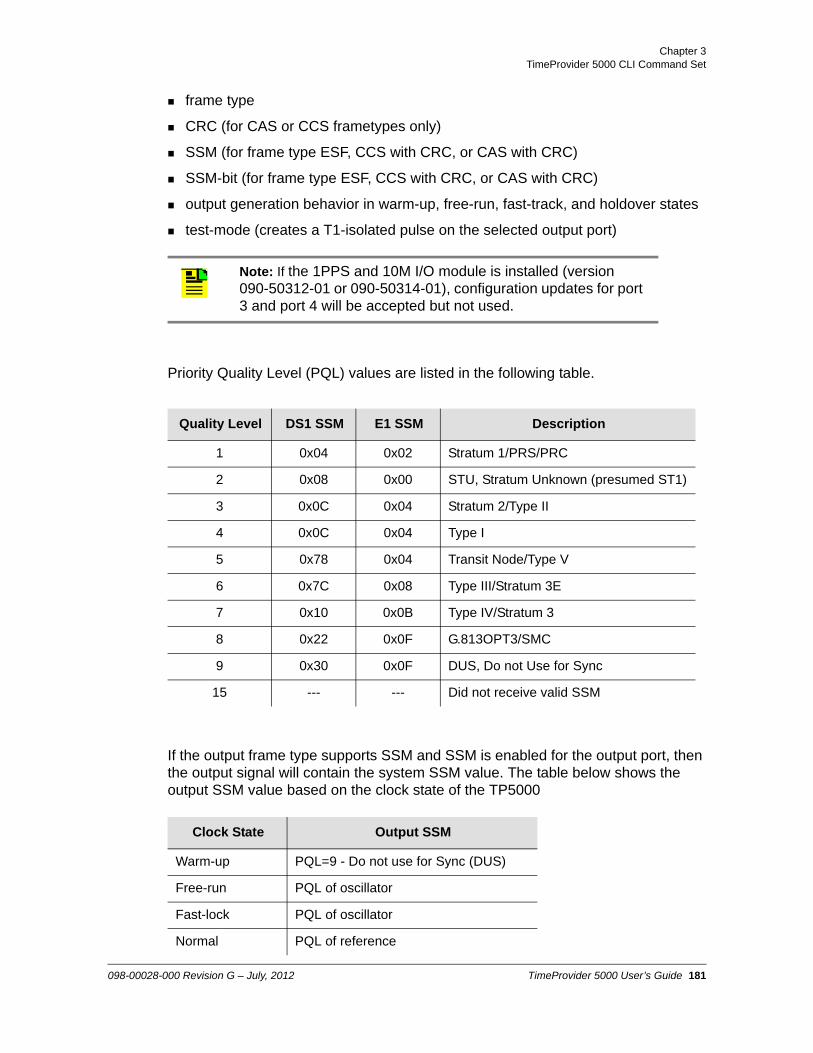
Chapter 3TimeProvider 5000 CLI Command Set
frame type
CRC (for CAS or CCS frametypes only)
SSM (for frame type ESF, CCS with CRC, or CAS with CRC)
SSM-bit (for frame type ESF, CCS with CRC, or CAS with CRC)
output generation behavior in warm-up, free-run, fast-track, and holdover states
test-mode (creates a T1-isolated pulse on the selected output port)
Priority Quality Level (PQL) values are listed in the following table.
If the output frame type supports SSM and SSM is enabled for the output port, then the output signal will contain the system SSM value. The table below shows the output SSM value based on the clock state of the TP5000
Note: If the 1PPS and 10M I/O module is installed (version 090-50312-01 or 090-50314-01), configuration updates for port 3 and port 4 will be accepted but not used.
Quality Level DS1 SSM E1 SSM Description
1 0x04 0x02 Stratum 1/PRS/PRC
2 0x08 0x00 STU, Stratum Unknown (presumed ST1)
3 0x0C 0x04 Stratum 2/Type II
4 0x0C 0x04 Type I
5 0x78 0x04 Transit Node/Type V
6 0x7C 0x08 Type III/Stratum 3E
7 0x10 0x0B Type IV/Stratum 3
8 0x22 0x0F G.813OPT3/SMC
9 0x30 0x0F DUS, Do not Use for Sync
15 --- --- Did not receive valid SSM
Clock State Output SSM
Warm-up PQL=9 - Do not use for Sync (DUS)
Free-run PQL of oscillator
Fast-lock PQL of oscillator
Normal PQL of reference
098-00028-000 Revision G – July, 2012 TimeProvider 5000 User’s Guide 181

Chapter 3 TimeProvider 5000 CLI Command Set
Command Syntax:
To provision the state for the specified output port:
set output state {port1|port2|port3|port4} {enable|disable}
To provision the output frame type:
set output frametype {port1|port2|port3|port4}{ccs|cas|freq2048khz|d4|esf|freq1544khz}
To provision the CRC output:
set output crc {port1|port2|port3|port4} {enable|disable}
To provision the SSM output:
set output ssm {port1|port2|port3|port4} {enable|disable}
To provision the output ssm-bit:
set output ssm-bit {port1|port2|port3|port4} [4 thru 8]
To provision the output behavior during the warm-up state:
set output warm-up {port1|port2|port3|port4} {on|squelch|ais}
Bridging Last PQL of reference
Holdover PQL of oscillator
Note: Enabling the output state for a programmable I/O port with the “Set Output state” command will also set that port as an output port and set the input state for that port to Disable.
Enabling the input state for a programmable I/O port with the “set input state” command will also set that port as an input port and set the output state for that port to Disable.
Note: The default output frame type is freq2048khz.
Note: The T1 isolated pulse mode has precedence over other frame types. This setting is not stored in non-volatile memory.
Clock State Output SSM
182 TimeProvider 5000 User’s Guide 098-00028-000 Revision G – July, 2012

Chapter 3TimeProvider 5000 CLI Command Set
To provision the output behavior during the free-run state:
set output free-run {port1|port2|port3|port4} {on|squelch|ais}
To provision the output behavior during the holdover state:
set output holdover {port1|port2|port3|port4} {on|squelch|ais}
To provision the output behavior during the fast-track state:
set output fast-track {port1|port2|port3|port4} {on|squelch|ais}
To enable the output test mode:
set output-test-mode {port1|port2|port3|port4} [t1pulse|disable]
Example 1:
To Enable output Port 2:
tp5000> set output state port2 enable
Example 2:
To set the frame type to 2048 kHz for output Port 1:
tp5000> set output frametype port1 freq2048khz
Example 3:
To Enable CRC for output Port 3:
tp5000> set output crc port3 enable
Example 4:
To Enable SSM for output Port 2:
tp5000> set output ssm port2 enable
Example 5:
To provision the SSM Bit value for E1 signals to 6 for output port2:
tp5000> set output ssm-bit port2 6
Example 6:
To provision the output behavior to squelch during the warm-up state for port2:
098-00028-000 Revision G – July, 2012 TimeProvider 5000 User’s Guide 183

Chapter 3 TimeProvider 5000 CLI Command Set
tp5000> set output warm-up port2 squelch
Example 7:
To provision the output behavior to squelch during the free-run state for port2:
tp5000> set output free-run port2 squelch
Example 8:
To provision the output behavior to ON during the holdover state for port2:
tp5000> set output holdover port2 on
Example 9:
To provision the output behavior to ON during the fast-track state for port2:
tp5000> set output fast-track port2 on
Example 10:
To generate a T1-isolated pulse on the selected output port:
tp5000> set output test-mode port2 t1pulse
Level : Config and Admin only
184 TimeProvider 5000 User’s Guide 098-00028-000 Revision G – July, 2012

Chapter 3TimeProvider 5000 CLI Command Set
show output-10m-config
This command displays the System's 10 MHz Output Port state, as well as the provisioned behavior of the 10 MHz Output Port during the warm-up, free-run, and holdover states.
Command Syntax:
show output-10m-config
Example:
tp5000> show output-10m-config
Response:
10MHz output configuration:
Port status - enable10MHz generation warm-up - squelch10MHz generation free-run - squelch10MHz generation fast-track - on10MHz generation holdover - on
Level : User, Config, and Admin
set output-10m
Use this command to provision the System's 10 MHz Output Port state. It is also used to provision the behavior of the 10 MHz Output Port during the warm-up, free-run, and holdover states.
Command Syntax:
To provision the state of the the 10 MHz output port:
set output-10m state [enable|disable]
To provision the output behavior during the warm-up state:
set output-10m warm-up {on|squelch}
To provision the output behavior during the free-run state:
set output-10m free-run {on|squelch}
To provision the output behavior during the fast-track state:
set output-10m fast-track {on|squelch}
To provision the output behavior during the holdover state:
098-00028-000 Revision G – July, 2012 TimeProvider 5000 User’s Guide 185

Chapter 3 TimeProvider 5000 CLI Command Set
set output-10m holdover {on|squelch}
Example 1:
To Enable the 10MHz output port
tp5000> set output-10m state enable
Example 2:
To provision the output behavior to squelch during the warm-up state for the dedicated 10MHz output port:
tp5000> set output-10m warm-up squelch
Example 3:
To provision the output behavior to squelch during the free-run state for the dedicated 10MHz output port:
tp5000> set output-10m free-run squelch
Example 4:
To provision the output behavior to ON during the fast-track state for the dedicated 10MHz output port:
tp5000> set output-10m fast-track on
Example 5:
To provision the output behavior to ON during the holdover state for the dedicated 10MHz output port:
tp5000> set output-10m holdover on
Level : Config and Admin only
186 TimeProvider 5000 User’s Guide 098-00028-000 Revision G – July, 2012

Chapter 3TimeProvider 5000 CLI Command Set
show output-exp
This command displays the E1 or 1PPS+TOD output port configuration and status in E1-TOD expansion shelf.
Command Syntax:
show output-exp { e1 | pps-tod } exp[0-9]
Example:
tp5000> show output-exp e1 exp0
Level : User, Config, and Admin
set output-exp
Use this command to provision the E1 and 1PPS+TOD output ports on the expansion shelf. This command allows you to provision:
state
frame type
CRC (for CAS or CCS frametypes only)
SSM (for frame type ESF, CCS with CRC, or CAS with CRC)
SSM-bit (for frame type ESF, CCS with CRC, or CAS with CRC)
output generation behavior in warm-up, free-run, fast-track, and holdover states
Priority Quality Level (PQL) values are listed in the following table.
Quality Level DS1 SSM E1 SSM Description
1 0x04 0x02 Stratum 1/PRS/PRC
2 0x08 0x00 STU, Stratum Unknown (presumed ST1)
3 0x0C 0x04 Stratum 2/Type II
4 0x0C 0x04 Type I
5 0x78 0x04 Transit Node/Type V
6 0x7C 0x08 Type III/Stratum 3E
098-00028-000 Revision G – July, 2012 TimeProvider 5000 User’s Guide 187
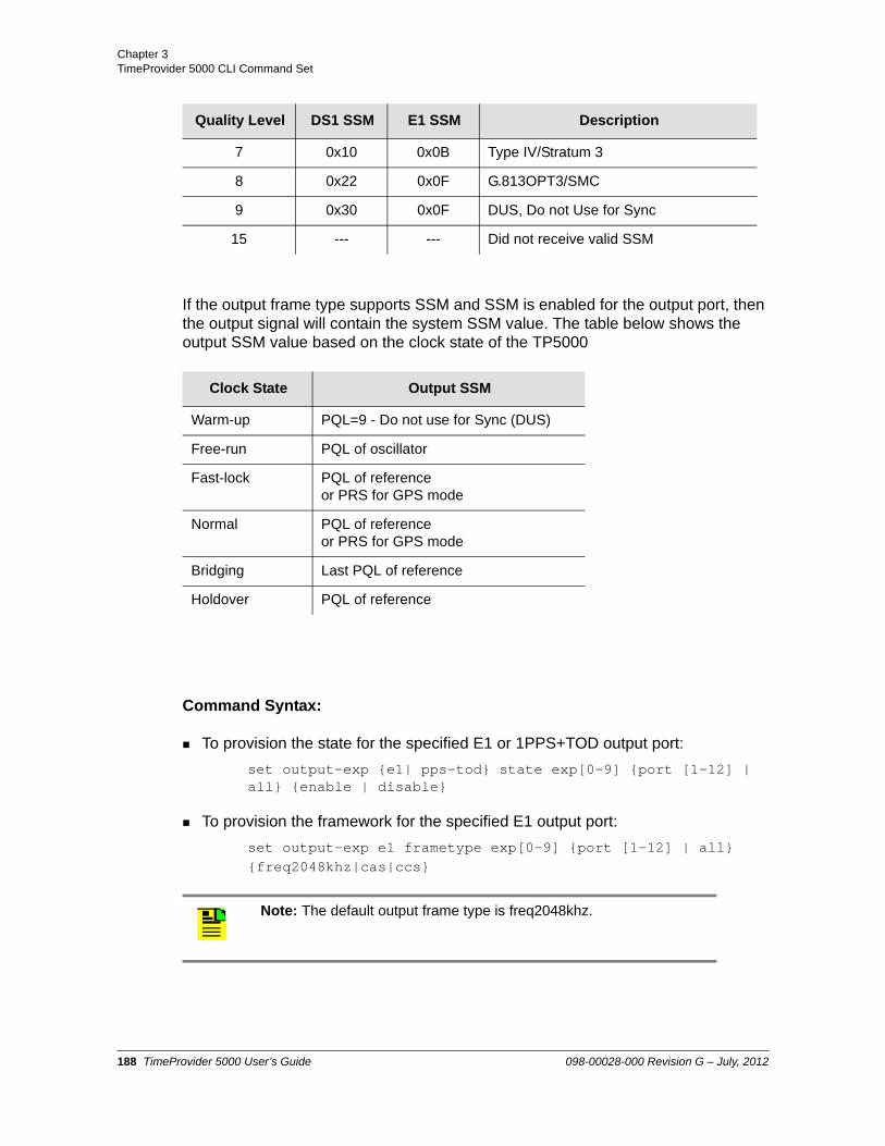
Chapter 3 TimeProvider 5000 CLI Command Set
If the output frame type supports SSM and SSM is enabled for the output port, then the output signal will contain the system SSM value. The table below shows the output SSM value based on the clock state of the TP5000
Command Syntax:
To provision the state for the specified E1 or 1PPS+TOD output port:
set output-exp {e1| pps-tod} state exp[0-9] {port [1-12] | all} {enable | disable}
To provision the framework for the specified E1 output port:
set output-exp e1 frametype exp[0-9] {port [1-12] | all}{freq2048khz|cas|ccs}
7 0x10 0x0B Type IV/Stratum 3
8 0x22 0x0F G.813OPT3/SMC
9 0x30 0x0F DUS, Do not Use for Sync
15 --- --- Did not receive valid SSM
Clock State Output SSM
Warm-up PQL=9 - Do not use for Sync (DUS)
Free-run PQL of oscillator
Fast-lock PQL of reference or PRS for GPS mode
Normal PQL of reference or PRS for GPS mode
Bridging Last PQL of reference
Holdover PQL of reference
Note: The default output frame type is freq2048khz.
Quality Level DS1 SSM E1 SSM Description
188 TimeProvider 5000 User’s Guide 098-00028-000 Revision G – July, 2012

Chapter 3TimeProvider 5000 CLI Command Set
To provision the CRC output for the specified E1 output port:
set output-exp e1 crc exp[0-9] {port [1-12] | all} {enable|disable}
To provision the SSM output for the specified E1 output port:
set output-exp e1 ssm exp[0-9] {port [1-12] | all} {enable|disable}
To provision the output ssm-bit for the specified E1 output port:
set output-exp e1 ssm-bit exp[0-9] {port [1-12] | all} [4|5|6|7|8]
To provision the output behavior during the warm-up state for the specified E1 output port::
set output-exp e1 warm-up exp[0-9] {port [1-12] | all} {on|squelch|ais}
To provision the output behavior during the free-run state for the specified E1 output port::
set output-exp e1 free-run exp[0-9] {port [1-12] | all} {on|squelch|ais}
To provision the output behavior during the holdover state:
set output-exp e1 holdover exp[0-9] {port [1-12] | all} {on|squelch|ais}
To provision the output behavior during the fast-track state:
set output-exp e1 fast-track exp[0-9] {port [1-12] | all} {on|squelch|ais}
To provision the output behavior during the warm-up state for the specified 1PPS+TOD output port::
set output-exp pps-tod warm-up exp[0-9] {port [1-12] | all} {on|squelch}
To provision the output behavior during the free-run state for the specified 1PPS+TOD output port:
set output-exp pps-tod free-run exp[0-9] {port [1-12] | all} {on|squelch}
To provision the output behavior during the holdover state for the specified 1PPS+TOD output port:
Note: The T1 isolated pulse mode has precedence over other frame types. This setting is not stored in non-volatile memory.
098-00028-000 Revision G – July, 2012 TimeProvider 5000 User’s Guide 189

Chapter 3 TimeProvider 5000 CLI Command Set
set output-exp pps-tod holdover exp[0-9] {port [1-12] | all} {on|squelch}
To provision the output behavior during the fast-track state for the specified 1PPS+TOD output port:
set output-exp pps-tod fast-track exp[0-9] {port [1-12] | all} {on|squelch}
Example 1:
To Enable all E1 output ports on expansion shelf 3 (id=exp2):
tp5000> set output-exp e1 exp2 all enable
Example 1a:
To Enable 1PPS+TOD output port #6 on expansion shelf 3 (id=exp2):
tp5000> set output-exp pps-tod exp2 port6 enable
Example 2:
To set the frame type to 2048 kHz for E1 output Port 10 on expansion shelf 5 (id=exp4):
tp5000> set output-exp e1 frametype exp4 port10 freq2048khz
Example 3:
To Enable CRC for E1 output Port 3 on expansion shelf 4 (id=exp3):
tp5000> set output-exp e1 crc exp3 port3 enable
Example 4:
To Enable SSM for E1 output Port 9 on expansion shelf 8 (id=exp7):
tp5000> set output-exp e1 ssm exp7 port9 enable
Example 5:
To provision the SSM Bit value to 6 for E1 output Port 9 on expansion shelf 8 (id=exp7):
tp5000> set output-exp e1 ssm-bit exp7 port9 6
Example 6:
To provision the output behavior to squelch during the warm-up state for E1 output Port 9 on expansion shelf 8 (id=exp7):
190 TimeProvider 5000 User’s Guide 098-00028-000 Revision G – July, 2012

Chapter 3TimeProvider 5000 CLI Command Set
tp5000> set output-exp e1 warm-up exp7 port9 squelch
Example 7:
To provision the output behavior to squelch during the free-run state for E1 output Port 9 on expansion shelf 8 (id=exp7):
tp5000> set output-exp e1 free-run exp7 port9 squelch
Example 8:
To provision the output behavior to ON during the holdover state for E1 output Port 9 on expansion shelf 8 (id=exp7):
tp5000> set output-exp e1 holdover exp7 port9 on
Example 9:
To provision the output behavior to ON during the fast-track state for E1 output Port 9 on expansion shelf 8 (id=exp7):
tp5000> set output-exp e1 fast-track exp7 port9 on
Example 10:
To provision the output behavior to squelch during the warm-up state for E1 output Port 9 on expansion shelf 8 (id=exp7):
tp5000> set output-exp e1 warm-up exp7 port9 squelch
Example 11:
To provision the output behavior to squelch during the free-run state for E1 output Port 9 on expansion shelf 8 (id=exp7):
tp5000> set output-exp e1 free-run exp7 port9 squelch
Example 12:
To provision the output behavior to ON during the holdover state for E1 output Port 9 on expansion shelf 8 (id=exp7):
tp5000> set output-exp e1 holdover exp7 port9 on
Example 13:
To provision the output behavior to ON during the fast-track state for E1 output Port 9 on expansion shelf 8 (id=exp7):
tp5000> set output-exp e1 fast-track exp7 port9 on
Level : Config and Admin only
098-00028-000 Revision G – July, 2012 TimeProvider 5000 User’s Guide 191

Chapter 3 TimeProvider 5000 CLI Command Set
show output-pps-config
This command displays the System's 1PPS Output Port state, as well as the provisioned behavior of the 1PPS Output Port during the warm-up, free-run, and holdover states.
Command Syntax:
show output-pps-config
Example:
tp5000> show output-pps-config
Response:
1PPS output configuration:
Port state - enable1pps generation warm-up - squelch1pps generation free-run - squelch1pps generation fast-track - on1pps generation holdover - on
Level : User, Config, and Admin
set output-pps
Use this command to provision the System's 1PPS Output Port state. It is also used to provision the behavior of the 1PPS Output Port during the warm-up, free-run, and holdover states.
Command Syntax:
To provision the state of the the 1PPS output port:
set output-pps state [enable|disable]
To provision the output behavior during the warm-up state:
set output-pps warm-up {on|squelch
To provision the output behavior during the free-run state:
set output-pps free-run {on|squelch}
To provision the output behavior during the fast-track state:
set output-pps fast-track {on|squelch}
To provision the output behavior during the holdover state:
set output-pps holdover {on|squelch}
192 TimeProvider 5000 User’s Guide 098-00028-000 Revision G – July, 2012

Chapter 3TimeProvider 5000 CLI Command Set
Example 1:
To Enable the 1PPS output port
tp5000> set output-pps state enable
Example 2:
To provision the output behavior to squelch during the warm-up state for the dedicated 1PPS output port:
tp5000> set output-pps warm-up squelch
Example 3:
To provision the output behavior to squelch during the free-run state for the dedicated 1PPS output port:
tp5000> set output-pps free-run squelch
Example 4:
To provision the output behavior to ON during the fast-track state for the dedicated 1PPS output port:
tp5000> set output-pps fast-track on
Example 5:
To provision the output behavior to ON during the holdover state for the dedicated 1PPS output port:
tp5000> set output-pps holdover on
Level : Config and Admin only
098-00028-000 Revision G – July, 2012 TimeProvider 5000 User’s Guide 193

Chapter 3 TimeProvider 5000 CLI Command Set
show output-test-mode
This command displays the status of the output test mode for all output ports.
Command Syntax:
show output-test-mode
Example:
tp5000> show output-test-mode
Response:
Port 1 test mode - disablePort 2 test mode - disablePort 3 test mode - disablePort 4 test mode - disable
Related : Show Output-config, Set Output test-mode, Show Output-10M-config, Show Output-PPS-config
Level : User, Config, and Admin
194 TimeProvider 5000 User’s Guide 098-00028-000 Revision G – July, 2012

Chapter 3TimeProvider 5000 CLI Command Set
set packet-service
Use the set packet-service command to configure the specified port as either a PTP grandmaster, an NTP server, or a PTP probe. A license is required for a packet service other than PTP grandmaster. The packet-service mode for IOC ports can be set independently, with one port operating in PTP grandmaster mode while the other port is configured for ptp-probe mode (IP addresses must be set to different subnets).
Command Syntax:
set packet-service ioc1-x {ptp-gm | ntp-server | ptp-probe | ntp-probe}
Example 1:
To configure port 2 of the IOC card as a PTP grandmaster:
set packet-service ioc1-2 ptp-gm
Example 2:
To configure port 1 of the IOC card as an NTP server:
set packet-service ioc1-1 ntp-server
Example 3:
To configure port 2 of the IOC card as a PTP probe:
set packet-service ioc1-1 ptp-probe
Level : Admin only
Note: PTP-probe and NTP-server each require a separate license.
NTP-probe is shown as a packet -service choice, however, it is an internal feature reserved for Symmetricom use.
Note: The set packet-service command deprecates the set ptp-probe-mode {enable|disable} command.
098-00028-000 Revision G – July, 2012 TimeProvider 5000 User’s Guide 195

Chapter 3 TimeProvider 5000 CLI Command Set
password
Use this command to modify the password of the current user.
Command Syntax:
password
Example:
tp5000> password
Response:
Prompt for password
Prompt for password confirmation
Level : User, Config, and Admin
Note: Be sure to not lose or forget the password. Contact Symmetricom support for the password recovery procedure if all admin-level user passwords are lost.
196 TimeProvider 5000 User’s Guide 098-00028-000 Revision G – July, 2012

Chapter 3TimeProvider 5000 CLI Command Set
ping
Use this command to ping the host specified by the address (xxx.xxx.xxx.xxx) and display ping statistics.
Command Syntax:
ping {imc|ioc-1|ioc-2|exp[0-9} port{1-16]} [<vlan-id>] <ip-address>
Example 1:
For IMC address of 192.168.5.100
tp5000> ping imc 192.168.5.100 <enter>
Response 1:
Ping imc success
Example 2:
For port 1 on the active IOC card, IP address 192.168.5.110, with VLAN ID of 23
tp5000> ping ioc-1 23 192.168.5.110
Response 2:
Ping ioc-1 success
Example 3:
For port 2 on the active IOC card, IP address 192.168.5.112, with no VLAN
tp5000> ping ioc-2 192.168.5.112
Response 3:
Error: Action failed.Ping ioc-2 failed
Note: To minimize system resource usage and deter denial of service attacks, the system is configured to allow a maximum ICMP ping request rate of 1 per second.
098-00028-000 Revision G – July, 2012 TimeProvider 5000 User’s Guide 197

Chapter 3 TimeProvider 5000 CLI Command Set
Example 4:
For port 16 on the expansion shelf 4 (module id: exp3), IP address 192.168.5.110, with VLAN ID of 23
tp5000> ping exp3 port 6 23 192.168.5.110
Response 4:
Ping exp3 port 6 success
Level : User, Config, and Admin
198 TimeProvider 5000 User’s Guide 098-00028-000 Revision G – July, 2012

Chapter 3TimeProvider 5000 CLI Command Set
show pps-tod
This command displays the pps-tod input ports (port1 and port 2) configuration and status information.
Command Syntax:
To show pps-tod input ports configuration:
show pps-tod config
To show pps-tod input ports status:
show pps-tod status
Example 1:
tp5000>show pps-tod config
Response 1:
PPS-TOD Input Ports Configuration
----------------------------------------------------------------------| Port ID | State | Priority | Cable Delay | PQL State | PQL Value ||.........|.........|..........|.............|...........|...........|| Port 1 | enable | 3 | 0 | disable | 1 ||.........|.........|..........|.............|...........|...........|| Port 2 | enable | 4 | 0 | disable | 1 ||.........|.........|..........|.............|...........|...........|
Example 2:
tp5000>show pps-tod status
Response 2:
PPS-TOD Input Ports Status
098-00028-000 Revision G – July, 2012 TimeProvider 5000 User’s Guide 199

Chapter 3 TimeProvider 5000 CLI Command Set
-------------------------------------------------------------------| Status | Port 1 | Port 2 ||----------------------------------------------|-------------------|| Port status | normal | disabled|error | |....................|.........................|...................|| PPS status | normal | n/a | |....................|.........................|...................||PPS phase offset(ns)| 10 | n/a | |....................|.........................|...................|| Clock source type | 0x00 | n/a | |....................|.........................|...................|| Clock source status| 0x00 | n/a | |....................|.........................|...................|| Accuracy | <value> | n/a | |....................|.........................|...................|| Alarm | 0x00 | n/a | |....................|.........................|...................|
Level : User, Config, and Admin
set pps-tod
Function: to configure the pps-tod input ports state, the priority level, the cable-delay compensation.
Command Syntax:
To provision the state for the specified 1PPS+TOD port:
set pps-tod state {port1 | port2} {enable | disable}
To provision the priority of the 1PPS+TOD input port:
set pps-tod priority {port1 | port2} <1 - 16 >
To provision the cable-delay of pps-tod port:
set pps-tod cable-delay {port1 | port2} <value>
To set the forced PQL state for the specified 1PPS+TOD port
set pps-tod pql-state {port1 | port2} {enable | disable}
To set the forced PQL value for the specified 1PPS+TOD port
set pps-tod pql-value port {port1 | port2} <pql-value>
Ranges: priority = 1 — 16cable-delay = 0 — 200000 ns, 12.5 ns resolutionpql-value= 1 — 3
Example 1:
200 TimeProvider 5000 User’s Guide 098-00028-000 Revision G – July, 2012

Chapter 3TimeProvider 5000 CLI Command Set
To enable 1PPS-TOD port 1
set pps-tod state port1 enable
Example 2:
To provision the priority of the 1PPS+TOD input port 1 to a value of 5
tp5000> set pps-tod priority port1 5
Example 3:
To provision the cable delay value for the 1PPS+TOD input port 1 to a value of 2500 ns
tp5000> set pps-tod cable-delay port1 2500
Example 4:
To enable the 1PPS+TOD input port for a forced pql-value
tp5000> set pps-tod pql-state port1 enable
Example 5:
To provision the 1PPS+TOD input port 1 to a forced pql-value of 3
tp5000> set pps-tod pql-value port1 3
Level: Config, and Admin only
098-00028-000 Revision G – July, 2012 TimeProvider 5000 User’s Guide 201

Chapter 3 TimeProvider 5000 CLI Command Set
show pql-ssm
This command displays the Priority Quality Level (PQL) values for reference input signal types. The PQL corresponds to the “ssm-value” parameter that is used with the “set input” command. The PQL is a representation of traceability for the signal presented at the input ports, where a PQL value of 15 represents an invalid SSM. If SSM is disabled for an input port, then the TP5000 will use the user-assigned SSM-value (PQL) for that input port.
Command Syntax:
show pql-ssm
Example:
tp5000> show pql-ssm
Response:
Option 1 Table
---------------------------------------------------------| Option 1 SSM hex | Clock QL | PTP clockClass | PQL ||------------------|-------------|----------------|-----|| 0x02 | QL-PRC | 84 | 1 ||..................|.............|................|.....|| 0x00 | STU | 82 | 2 ||..................|.............|................|.....|| 0x04 | QL-SSU-A | 90 | 3 ||..................|.............|................|.....|| 0x04 | Type I | 90 | 4 ||..................|.............|................|.....|| 0x08 | QL-SSU-B | 96 | 6 ||..................|.............|................|.....|| 0x0B | QL-SEC/EEC1 | 104 | 7 ||..................|.............|................|.....|| 0x0F | QL-DNU | 110 | 9 ||..................|.............|................|.....|| Others(or absent)| Invalid | n/a | 15 |---------------------------------------------------------
Option 2 Table
Note: SSM during bridging will be the last SSM value of input reference while clock was in normal lock state.
202 TimeProvider 5000 User’s Guide 098-00028-000 Revision G – July, 2012

Chapter 3TimeProvider 5000 CLI Command Set
---------------------------------------------------------| Option 2 SSM hex | Clock QL | PTP clockClass | PQL ||------------------|-------------|----------------|-----|| 0x04FF | QL-PRS | 80 | 1 ||..................|.............|................|.....|| 0x08FF | QL-STU | 82 | 2 ||..................|.............|................|.....|| 0x0CFF | QL-ST2 | 86 | 3 ||..................|.............|................|.....|| 0x0CFF | Type I | 86 | 4 ||..................|.............|................|.....|| 0x78FF | QL-TNC | 90 | 5 ||..................|.............|................|.....|| 0x7CFF | QL-ST3E | 100 | 6 ||..................|.............|................|.....|| 0x10FF | QL-ST3/EEC2 | 102 | 7 ||..................|.............|................|.....|| 0x22FF | QL-SMC | 106 | 8 ||..................|.............|................|.....|| 0x30FF | QL-DUS | 110 | 9 ||..................|.............|................|.....|| Others(or absent)| Invalid | n/a | 15 |---------------------------------------------------------
Related : set input, Set Output
Level : User, Config, and Admin
098-00028-000 Revision G – July, 2012 TimeProvider 5000 User’s Guide 203

Chapter 3 TimeProvider 5000 CLI Command Set
set ptp
Use this command to provision the PTP port’s common provisioned attributes, multicast-specific attributes, and unicast-specific attributes.
Common Provisioned Attributes:PTP Profile, Management Addressing mode (Multicast/Unicast), Two-step Clock mode, Alternate Master flag, IP Header Time to Live (TTL) field, Timescale, PTP state, Clock ID, Priority 1, Priority 2, Domain, Diffserv State, Diffserv Code Point, Dither, Maximum clients, Announce limit, Synchronization limit, Delay limit. See Figure 4-10, Figure 4-11, and Figure 4-12 for diagrams of the hierarchy for the PTP- Common commands.
See Table 4-11 for descriptions of the common provisioned attributes.
Multicast Specific Attributes:Announce Message Timeout, Client Timeout, VLAN ID, Sync Message Interval, Announce Message Interval, Delay Interval. See Figure 4-13 for a diagram of the hierchy for the PTP Multicast commands.
See Table 4-12 for descriptions of the attributes specific to Multicast.
Unicast Specific Attributes – Non-Fixed:Unicast Negotiation state, Dynamic Lease Interval. See Figure 4-14 for a diagram of the hierchy for the PTP Unicast – Non-Fixed commands.
See Table 4-13 for descriptions of the attributes specific to Unicast – Non-Fixed.
Unicast Specific Attributes - Static:Unicast IP addresses (up to 10), Unicast State, Unicast Clock ID, VLAN ID, Sync Message Interval, Announce Message Interval, Delay Interval. See Figure 4-15 for a diagram of the hierchy for the Unicast - Static commands.
See Table 4-14 for descriptions of the attributes specific to Unicast -Static.
Expansion Shelf-Specific Attributes:State, Timescale, Two-step Clock mode, Alternate-Master, Priority 1, Priority 2, Domain, Dither, and Clock ID
Command Syntax:
Common Attributes:
To provision the PTP profile for the grandmaster:
Note: This is a special mode which allows the TP5000 user to pre-allocate service for up to designated 10 clients, rather than using dynamic unicast negotiation of leases.
204 TimeProvider 5000 User’s Guide 098-00028-000 Revision G – July, 2012

Chapter 3TimeProvider 5000 CLI Command Set
set ptp profile ioc1-[y] {default | hybrid | itu-g8265-1 | telecom-2008}
To provision the management addressing mode as Multicast or Unicast:
set ptp mgmt-addr-mode ioc1-[y] {unicast | multicast}
To provision the state of the Two-Step Clock mode:
set ptp two-step {ioc1-1 | ioc1-2 | exp[0-9]} {enable | disable}
– If the Two-Step Clock state is Disable, a One-Step Clock is used.
To provision the timescale for IOC1 or expansion shelf 1 -10 (id= exp0 - exp9) to Automatic, Arbitrary or PTP:
set ptp timescale {ioc1 | exp[0-9]} {auto| arb | ptp}
– If the timescale is set to “auto”, the TP5000 will make the decision based on the input. The TP5000 will set the timescale to “ptp” if the unit is locked to gps. The TP5000 will set the timescale to “arb” if the unit is locked to any other reference besides gps (i.e. E1 and T1).
To provision the Alternate Master mode:
set ptp alternative-master {ioc1-1 | ioc1-2 | exp[0-9]} {enable | disable}
To provision the state for the specified PTP port on the IOC card or expansion shelf:
set ptp state {ioc1-1 | ioc1-2 | exp[0-9]} {enable | disable}
To provision the IP Header Time to Live (TTL) field for PTP packets:
set ptp ttl {ioc1-1 | ioc1-2} <TTL-value>
To provision the PTP maximum number of clients:
Note: The ptp profile command replaces the ptp addr-mode command.
Note: Management addressing mode controls whether PTP management messages use Multicast or Unicast. This is independent of the set ptp profile command. For example, management addressing can be set for Multicast while PTP synchronization is using Unicast. For multicast management, the client must be in the TP5000's client list.
Note: If the Alternate Master mode is set to Enable, the alternate master flag will be set in the PTP messages.
098-00028-000 Revision G – July, 2012 TimeProvider 5000 User’s Guide 205

Chapter 3 TimeProvider 5000 CLI Command Set
set ptp max-client {ioc1-1 | ioc1-2} <max-client value>
To provision the announce limit, the minimum interval (maximum rate) between PTP announce messages:
set ptp announce-limit {ioc1-1 | ioc1-2} <announce-limit value>
– The interval is 2z seconds, where z= <announce-limit-value>.
To provision the synchronization limit, the minimum interval (maximum rate) between PTP synchronization messages:
set ptp sync-limit {ioc1-1 | ioc1-2} <sync-limit value>
– The interval is 2z seconds, where z= <sync-limit-value>.
To provision the delay limit, the minimum interval (maximum rate) between PTP delay response messages:
set ptp delay-limit {ioc1-1 | ioc1-2} <delay-limit value>
– The interval is 2z seconds, where z= <delay-limit-value>.
To provision the PTP priority-1:
set ptp priority-1 {ioc1-1 | ioc1-2 | exp[0-9]} <priority-1 value>
To provision the PTP priority-2:
set ptp priority-2 {ioc1-1 | ioc1-2 | exp[0-9]} <priority-2 value>
To provision the PTP domain:
set ptp domain {ioc1-1 | ioc1-2 | exp[0-9]} <domain-value>
To provision the PTP Diffserv Code Point value:
set ptp dscp ioc1-[y] <dscp-value>
To provision the PTP Diffserv Code Point state:
set ptp dscp-state ioc1-[y] {enable | disable}
To provision the PTP dither:
set ptp dither {ioc1-1 | ioc1-2 | exp[0-9]} {enable | disable}
To provision the PTP master Clock ID:
set ptp clockid {ioc1-1 | ioc1-2 | exp[0-9]} <clockid>
where the Clock ID is in the form xx:xx:xx:xx:xx:xx:xx:xx
206 TimeProvider 5000 User’s Guide 098-00028-000 Revision G – July, 2012

Chapter 3TimeProvider 5000 CLI Command Set
Multicast Specific Attributes - TP 5000:
To provision the PTP Multicast client timeout value:
set ptp multicast client-timeout {ioc1-1 | ioc1-2 | exp[0-9]} <timeout-value>
To provision the PTP Multicast announce timeout value:
set ptp multicast announce-timeout {ioc1-1 | ioc1-2 | exp[0-9] port<1-16>} <timeout-value>
where
y= 1|2, the port number
To provision the PTP Multicast VLAN ID:
set ptp multicast vlanid {ioc1-1 | ioc1-2} <vlanid-value>
To provision the interval between announce messages for PTP Multicast:
set ptp multicast announce-int {ioc1-1 | ioc1-2 | exp[0-9] port<1-16>} <announce-int-value>
– The interval is 2z seconds, where z= <announce-int-value>.
To provision the interval between synchronization messages for PTP Multicast:
set ptp multicast sync-int {ioc1-1 | ioc1-2 | exp[0-9] port<1-16>} <sync-int-value>
– The interval is 2z seconds, where z= <sync-int-value>.
To provision the interval between delay response messages for PTP Multicast:
set ptp multicast delay-int {ioc1-1 | ioc1-2 | exp[0-9] port<1-16>} <delay-int-value>
– The interval is 2z seconds, where z= <sync-int-value>.
Unicast Specific Attributes – Non-Fixed:
To provision the PTP unicast dynamic negotiation state:
set ptp unicast dynamic negotiate {ioc1-1 | ioc1-2} {enable|disable}
Note: The VLAN must be configured with the set vlan command.
098-00028-000 Revision G – July, 2012 TimeProvider 5000 User’s Guide 207
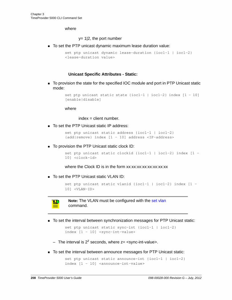
Chapter 3 TimeProvider 5000 CLI Command Set
where
y= 1|2, the port number
To set the PTP unicast dynamic maximum lease duration value:
set ptp unicast dynamic lease-duration {ioc1-1 | ioc1-2} <lease-duration value>
Unicast Specific Attributes - Static:
To provision the state for the specified IOC module and port in PTP Unicast static mode:
set ptp unicast static state {ioc1-1 | ioc1-2} index [1 - 10] [enable|disable]
where
index = client number.
To set the PTP Unicast static IP address:
set ptp unicast static address {ioc1-1 | ioc1-2} {add|remove} index [1 - 10] address <IP-address>
To provision the PTP Unicast static clock ID:
set ptp unicast static clockid {ioc1-1 | ioc1-2} index [1 - 10] <clock-id>
where the Clock ID is in the form xx:xx:xx:xx:xx:xx:xx:xx
To set the PTP Unicast static VLAN ID:
set ptp unicast static vlanid {ioc1-1 | ioc1-2} index [1 - 10] <VLAN-ID>
To set the interval between synchronization messages for PTP Unicast static:
set ptp unicast static sync-int {ioc1-1 | ioc1-2} index [1 - 10] <sync-int-value>
– The interval is 2z seconds, where z= <sync-int-value>.
To set the interval between announce messages for PTP Unicast static:
set ptp unicast static announce-int {ioc1-1 | ioc1-2} index [1 - 10] <announce-int-value>
Note: The VLAN must be configured with the set vlan command.
208 TimeProvider 5000 User’s Guide 098-00028-000 Revision G – July, 2012

Chapter 3TimeProvider 5000 CLI Command Set
– The interval is 2z seconds, where z= <announce-int-value>.
To provision the interval between delay response messages for PTP Unicast static:
set ptp unicast static delay-int {ioc1-1 | ioc1-2} index [1 - 10] <delay-int-value>
– The interval is 2z seconds, where z= <delay-limit-value>.
Expansion Shelf Attributes (Multicast):
To provision the state of the PTP outputs for the PTP/Synce expansion shelf:
set ptp state exp[0-9] [port[1-16] | all] [enable | disable]
To provision the PTP timescale for the PTP/Synce expansion shelf:
set ptp timescale exp[0-9] [auto | arb | ptp]
To provision the PTP clock to two-step or one-step mode for the PTP/Synce expansion shelf:
set ptp two-step exp[0-9] [enable | disable]
To provision the PTP alternate-master for the PTP/Synce expansion shelf:
set ptp alternate-master exp[0-9] [enable | disable]
To provision the Priority 1 value for the PTP/Synce expansion shelf:
set ptp priority1 exp[0-9] <priority1-value>
To provision the Priority 2 value for the PTP/Synce expansion shelf:
set ptp priority2 exp[0-9] <priority2-value>
To provision domain for the PTP/Synce expansion shelf:
set ptp domain exp[0-9] <domain-value>
To provision the dither for the for the PTP/Synce expansion shelf:
set ptp dither exp[0-9] [enable | disable]
To provision the clock ID for the PTP/Synce expansion shelf:
set ptp clockid exp[0-9] <clockid-value>
Note: : If the Alternate Master mode is set to Enable, the alternate master flag will be set in the PTP messages. If the alternate master flag is set, the TP5000 will not run the Best Master Clock (BMC) algorithm and will stay in master mode.
098-00028-000 Revision G – July, 2012 TimeProvider 5000 User’s Guide 209
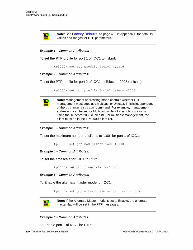
Chapter 3 TimeProvider 5000 CLI Command Set
Example 1Common Attributes:
To set the PTP profile for port 1 of IOC1 to hybrid:
tp5000> set ptp profile ioc1-1 hybrid
Example 2Common Attributes:
To set the PTP profile for port 2 of IOC1 to Telecom-2008 (unicast):
tp5000> set ptp profile ioc1-1 telecom-2008
Example 3Common Attributes:
To set the maximum number of clients to “100” for port 1 of IOC1:
tp5000> set ptp max-client ioc1-1 100
Example 4Common Attributes:
To set the timescale for IOC1 to PTP:
tp5000> set ptp timescale ioc1 ptp
Example 5Common Attributes:
To Enable the alternate master mode for IOC1:
tp5000> set ptp alternative-master ioc1 enable
Example 6Common Attributes:
To Enable port 1 of IOC1 for PTP:
Note: See Factory Defaults, on page 466 in Appendix B for defaults values and ranges for PTP parameters.
Note: Management addressing mode controls whether PTP management messages use Multicast or Unicast. This is independent of the set ptp profile command. For example, management addressing can be set for Multicast while PTP synchronization is using the Telecom-2008 (Unicast). For multicast management, the client must be in the TP5000's client list.
Note: If the Alternate Master mode is set to Enable, the alternate master flag will be set in the PTP messages.
210 TimeProvider 5000 User’s Guide 098-00028-000 Revision G – July, 2012
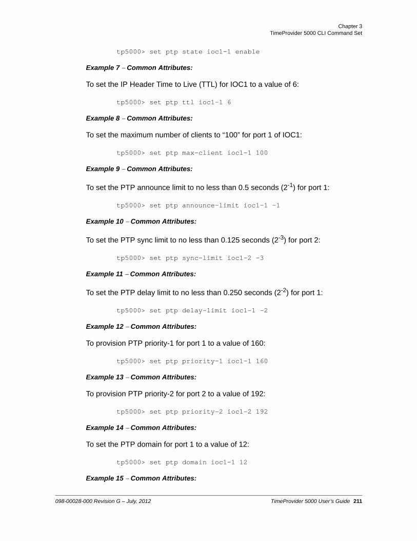
Chapter 3TimeProvider 5000 CLI Command Set
tp5000> set ptp state ioc1-1 enable
Example 7Common Attributes:
To set the IP Header Time to Live (TTL) for IOC1 to a value of 6:
tp5000> set ptp ttl ioc1-1 6
Example 8Common Attributes:
To set the maximum number of clients to “100” for port 1 of IOC1:
tp5000> set ptp max-client ioc1-1 100
Example 9Common Attributes:
To set the PTP announce limit to no less than 0.5 seconds (2-1) for port 1:
tp5000> set ptp announce-limit ioc1-1 -1
Example 10Common Attributes:
To set the PTP sync limit to no less than 0.125 seconds (2-3) for port 2:
tp5000> set ptp sync-limit ioc1-2 -3
Example 11Common Attributes:
To set the PTP delay limit to no less than 0.250 seconds (2-2) for port 1:
tp5000> set ptp delay-limit ioc1-1 -2
Example 12Common Attributes:
To provision PTP priority-1 for port 1 to a value of 160:
tp5000> set ptp priority-1 ioc1-1 160
Example 13Common Attributes:
To provision PTP priority-2 for port 2 to a value of 192:
tp5000> set ptp priority-2 ioc1-2 192
Example 14Common Attributes:
To set the PTP domain for port 1 to a value of 12:
tp5000> set ptp domain ioc1-1 12
Example 15Common Attributes:
098-00028-000 Revision G – July, 2012 TimeProvider 5000 User’s Guide 211

Chapter 3 TimeProvider 5000 CLI Command Set
To set the PTP Diffserv Code Point value for port 2 to a value of 21:
tp5000> set ptp dscp ioc1-2 21
Example 16Common Attributes:
To Enable the PTP Diffserv Code Point for port 1:
tp5000> set ptp dscp-state ioc1-1 enable
Example 17Common Attributes:
To Enable dither for port 1:
tp5000> set ptp dither ioc1-1 enable
Example 18Common Attributes:
To set the PTP master Clock ID for Port 1 to a value of AA:BB:11:22:33:44:55:66
tp5000> set ptp clockid ioc1-1 aa:bb:11:22:33:44:55:66
Example 19Multicast Attributes:
To set the PTP Multicast client timeout to 900 seconds for Port 1:
set ptp multicast client-timeout ioc1-1 900
Example 20Multicast Attributes:
To provision the PTP Multicast announce timeout to 5 for Port 1:
set ptp multicast announce-timeout ioc1-1 5
Example 21Multicast Attributes:
To provision the PTP Multicast VLAN ID to 12 for Port 1:
set ptp multicast vlanid ioc1-1 12
Example 22Multicast Attributes:
To provision the interval between announce messages to -6 (0.015625 seconds) for PTP Multicast on Port 2:
set ptp multicast announce-int ioc1-2 -6
Example 23Multicast Attributes:
To provision the interval between synchronization messages to -5 (0.03125 seconds) for PTP Multicast on Port 2:
212 TimeProvider 5000 User’s Guide 098-00028-000 Revision G – July, 2012

Chapter 3TimeProvider 5000 CLI Command Set
set ptp multicast sync-int ioc1-2 -5
Example 24Multicast Attributes:
To provision the interval between delay response messages to -4 (0.0625 seconds) for PTP Multicast on Port 2:
set ptp multicast delay-int ioc1-2 -4
Example 25Unicast - Dynamic:
To Enable PTP Unicast dynamic negotiation for port 1:
tp5000> set ptp unicast dynamic negotiate ioc1-1 enable
Example 26Unicast - Dynamic:
To set the PTP Unicast dynamic maximum lease duration value to 500 seconds:
tp5000> set ptp unicast dynamic lease-duration ioc1-1 500
Example 27 Unicast - Static:
Use the following procedure to configure IOC1, Port 1 for 2 Unicast Static clients:
Client 1: 10.11.11.101, VLAN ID=10, index=1, Clock ID: 0A:11:22:33:44:55:66:77,Synchronization interval rate = 16 per second (sync-int value = -4) , Announce interval rate = 1 per second (announce-int value = 0),Delay interval rate = 8 per second (delay-int value = -3)
Client 2: 10.21.21.101, VLAN ID=20, index=2, Clock ID: 0A:22:33:44:55:66:77:88Synchronization interval rate = 32 per second (sync-int value = -5) , Announce interval rate = 1 per second (announce-int value = 0),Delay interval rate = 16 per second (delay-int value = -4)
tp5000> set ptp profile ioc1-1 telecom-2008
tp5000> set ptp unicast static address ioc1-1 add index 1 10.11.11.101
tp5000> set ptp unicast static vlanid ioc1-1 index 1 vlanid 10
tp5000> set ptp unicast static clockid ioc1-1 index 1 0A:11:22:33:44:55:66:77
tp5000> set ptp unicast static sync-int ioc1-1 index 1 -4
Note: Each VLAN must be configured on a separate subnet. See Provisioning VLAN and the set vlan command for details.
098-00028-000 Revision G – July, 2012 TimeProvider 5000 User’s Guide 213

Chapter 3 TimeProvider 5000 CLI Command Set
tp5000> set ptp unicast static announce-int ioc1-1 index 1 0
tp5000> set ptp unicast static delay-int ioc1-1 index 1 -3
tp5000> set ptp unicast static state ioc1-1 index 1 enable
tp5000> set ptp unicast static address ioc1-1 add index 2 10.21.21.101
tp5000> set ptp unicast static vlanid ioc1-1 index 2 vlanid 20
tp5000> set ptp unicast static clockid ioc1-1 add index 2 0A:22:33:44:55:66:77:88
tp5000> set ptp unicast static sync-int ioc1-1 index 2 -5
tp5000> set ptp unicast static announce-int ioc1-1 index 2 0
Level : Config and Admin only
214 TimeProvider 5000 User’s Guide 098-00028-000 Revision G – July, 2012

Chapter 3TimeProvider 5000 CLI Command Set
show ptp client
Use this command to display the PTP client attributes:
Command Syntax:
To display the attributes for the specified PTP client for the specified PTP port :
show ptp client ioc-[y] address <ip-address>
To display the attributes for all PTP clients for the specified PTP port :
show ptp client { ioc-1 | ioc-2 | exp[0-9] port <1-16>} all
Example 1:
To show the PTP client attributes for the client on port 1 of the active IOC module at IP address 192.168.5.132:
tp5000> show ptp client ioc-1 address 192.168.5.33
Response 1:
IP Address VLAN PRI Clock Id Mode Ann Sync Delay192.168.5.33 0 0 00:B0:AE:FF:FE:01:1A:85 D 0 0 -6
Example 2:
To show the PTP client attributes for all clients on port 1 of the active IOC module:
tp5000> show ptp client ioc-1 all
Response 2:
IP Address VLAN PRI Clock Id Mode Ann Sync Delay
Note: The TP5000 uses a proprietary technique to create a list of clients in the multicast mode. A maximum of 500 clients can be added to the list.
In multicast mode, the TP5000 creates a client list by examining the received PTP delay request messages. In order for a client to be reliably added to the client list and not removed, the TP5000 needs to receive several hundred delay request messages during the client timeout period. If delay requests are sent at a slow rate, then the client-timeout value must be increased. Since one-way PTP operation does not use delay request and delay response messages, the client list will not be populated in this mode.
098-00028-000 Revision G – July, 2012 TimeProvider 5000 User’s Guide 215

Chapter 3 TimeProvider 5000 CLI Command Set
192.168.5.13 0 0 00:B0:AE:FF:FE:01:1A:85 D 0 0 -6192.168.5.23 0 0 00:B0:AE:FF:FE:01:1B:85 D 0 0 -6192.168.5.33 0 0 00:B0:AE:FF:FE:01:1C:85 D 0 0 -6
Example 3:
To show the PTP client attributes for all clients on port 10 of the expansion shelf ID=9, and the PTP is in L2 mode:
tp5000> show ptp client exp9 port 10 all
Response 3:
IP Address VLAN PRI Clock Id Mode Ann Sync Delay0.0.0.0 0 0 00:B0:AE:FF:FE:01:1A:85 D 0 0 -60.0.0.0 0 0 00:B0:AE:FF:FE:01:1B:85 D 0 0 -6
0.0.0.0 0 0 00:B0:AE:FF:FE:01:1C:85 D 0 0 -6
Level : Config and Admin only
set ptp client-disconnect
Use this command to disconnect a PTP client using its clock ID,
Command Syntax:
set ptp client-disconnect ioc-[x] <client-clock-ID-value>
Example:
To disconnect the PTP client on IOC1-1 with clock ID value of 0A:11:22:33:44:55:66:77:
tp5000> set ptp client-disconnect ioc-1 0A:11:22:33:44:55:66:77
Level : Config and Admin
Note: Only Ethernet L2 is supported in expansion shelves until future release, and the IP address field is filled as 0.0.0.0
216 TimeProvider 5000 User’s Guide 098-00028-000 Revision G – July, 2012

Chapter 3TimeProvider 5000 CLI Command Set
show ptp-config
Use these commands to display the PTP port’s common provisioned attributes, multicast-specific attributes, and unicast-specific attributes.
Common Provisioned Attributes:
PTP Address Mode, Management Address Mode, TTL, Alternate Master, Clock ID, PTP state, two-step, priority1, priority2, domain, DiffServ code point, maximum number of clients, sync limit, announce limit, delay limit, unicast negotiation, unicast lease interval, dither
Multicast Specific Attributes:
Announce Message Timeout, Client Timeout, VLAN ID, Sync Message Interval, Announce Message Interval, Delay Message Interval
Unicast-Static Specific Attributes:
Unicast IP addresses, VLAN ID, Sync Message Interval, Announce Message Interval, Delay Interval, Clock ID
Command Syntax:
To display the specified PTP port’s common provisioned attributes:
show ptp config common { ioc1-1 | ioc1-2 | exp[0-9] port <1-16>}
To display the specified PTP port’s multicast provisioned attributes:
show ptp config multicast { ioc1-1 | ioc1-2 | exp[0-9] port <1-16>}
To display the specified PTP port’s unicast-static provisioned attributes:
show ptp config unicast {ioc1-1 | ioc1-2} index [1-10]
where
index= client number
Example 1:
To show the PTP Common mode configuration for Port 1 on the active IOC
tp5000> show ptp config common ioc1-1
Response 1:
098-00028-000 Revision G – July, 2012 TimeProvider 5000 User’s Guide 217

Chapter 3 TimeProvider 5000 CLI Command Set
PTP Timescale AUTOPTP State enabledPTP Max Number Clients 500PTP Profile itu-8265-1PTP ClockId 00:B0:AE:FF:FE:01:32:70PTP Priority 1 128PTP Priority 2 128PTP Domain 0PTP DSCP 0PTP DSCP State disabledPTP Sync Limit -7PTP Announce Limit -3PTP Delay Limit -7PTP Unicast Negotiation enabledPTP Unicast Lease Duration 1000PTP Dither disabledPTP Two Step enabledPTP TTL 16PTP Mgmt Addressing Mode multicastPTP Alternate Master disabled
Example 2:
To show the PTP Multicast mode configuration for Port 1 on the active IOC
tp5000> show ptp config multicast ioc1-1
Response 2:
PTP Multicast VlanId 35PTP Multicast Sync Intv 0PTP Multicast Announce Intv 0PTP Multicast Delay Intv -6PTP Multicast Announce Timeout 3PTP Multicast Client Timeout 1000
Example 3:
To show the PTP Unicast-static mode configuration for client 3 of Port 1 on active IOC
tp5000> show ptp config unicast ioc1-1
Response 3:
--------------------------------------------------------------------------------|Index|State |Address |VlanId|ClockId |Sync|Ann |Delay||.....|........|...............|......|........................|....|....|.....||1 |disabled|0.0.0.0 |5 |FF:FF:FF:FF:FF:FF:FF:FF |0 |1 |-3 ||.....|........|...............|......|........................|....|....|.....||2 |disabled|0.0.0.0 |0 |FF:FF:FF:FF:FF:FF:FF:FF |0 |1 |-3 ||.....|........|...............|......|........................|....|....|.....||3 |disabled|0.0.0.0 |0 |FF:FF:FF:FF:FF:FF:FF:FF |0 |1 |-3 ||.....|........|...............|......|........................|....|....|.....|
218 TimeProvider 5000 User’s Guide 098-00028-000 Revision G – July, 2012

Chapter 3TimeProvider 5000 CLI Command Set
|4 |disabled|0.0.0.0 |0 |FF:FF:FF:FF:FF:FF:FF:FF |0 |1 |-3 ||.....|........|...............|......|........................|....|....|.....||5 |disabled|0.0.0.0 |0 |FF:FF:FF:FF:FF:FF:FF:FF |0 |1 |-3 ||.....|........|...............|......|........................|....|....|.....||6 |disabled|0.0.0.0 |0 |FF:FF:FF:FF:FF:FF:FF:FF |0 |1 |-3 ||.....|........|...............|......|........................|....|....|.....||7 |disabled|0.0.0.0 |0 |FF:FF:FF:FF:FF:FF:FF:FF |0 |1 |-3 ||.....|........|...............|......|........................|....|....|.....||8 |disabled|0.0.0.0 |0 |FF:FF:FF:FF:FF:FF:FF:FF |0 |1 |-3 ||.....|........|...............|......|........................|....|....|.....||9 |disabled|0.0.0.0 |0 |FF:FF:FF:FF:FF:FF:FF:FF |0 |1 |-3 ||.....|........|...............|......|........................|....|....|.....||10 |disabled|0.0.0.0 |0 |FF:FF:FF:FF:FF:FF:FF:FF |0 |1 |-3 ||.....|........|...............|......|........................|....|....|.....|
Example 4:
To show the PTP Common mode configuration for Port 1 on the expansion shelf 7 (exp6)
tp5000> show ptp config common exp6 port 1
Response 4:
PTP Timescale AUTOPTP State enabledPTP Addressing Mode multicastPTP ClockId 00:B0:AE:FF:FE:01:32:70PTP Priority 1 128PTP Priority 2 128PTP Domain 0PTP Dither disabledPTP Two Step enabledPTP Alternate Master disabled
Example 5:
To show the PTP Multicast mode configuration for Port 1 on the expansion shelf 7 (exp6)
tp5000> show ptp config multicast exp6 port 1
Response 5:
PTP Multicast Sync Int 0PTP Multicast Announce Int 0PTP Multicast Delay Intv -6PTP Multicast Announce Timeout 3PTP Multicast Client Timeout 1000
Level : Config and Admin only
098-00028-000 Revision G – July, 2012 TimeProvider 5000 User’s Guide 219

Chapter 3 TimeProvider 5000 CLI Command Set
show ptp-node
This command sends a request for the Acceptable Master list, clock description, or client status to the TP500 found at the <client_ip> address.
This command can also send a NULL_MANAGEMENT message to the TP500 found at the <client_ip> address. If the targeted TP500 is successfully reached, the command response will indicate that the TP500 has acknowledged the message. This command performs a function similar to ping.
The acceptable master list, clock description, and null-management commands can also be used with other PTP clients that support PTP management messages.
Command Syntax:
To display the IP and VLAN address for the Acceptable Master for the specified PTP port and client:
show ptp-node acc-master ioc-[y] address <client_ip> [vlan-id <vlan>]
To display the clock description for the specified PTP port and client:
show ptp-node clock-description ioc-[y] address <client_ip> [vlan-id <vlan>]
To display the null management for the specified PTP port and client:
show ptp-node null-mgmt ioc-[y] address <client_ip> [vlan-id <vlan>]
To display the status of the specified client connected to the specified port:
show ptp-node status ioc-[y] address <client_ip> [vlan-id <vlan>]
where
y= 1|2, the port number on the IOC
Note: Per IEEE-1588-2008, the management TLV data field is of zero length. No action affecting data sets or state shall result from receiving this TLV. The receipt of a NULL_MANAGEMENT message shall adhere to the requirements of the actionField; see 15.4.1.6 in IEEE-1588-2008.
NULL_MANAGEMENT messages are typically used to test implementations by exercising the management handlers without producing any change in protocol operation. For example, such a message can be sent to test whether received management messages are being recorded in an implementation-specific event log.
220 TimeProvider 5000 User’s Guide 098-00028-000 Revision G – July, 2012
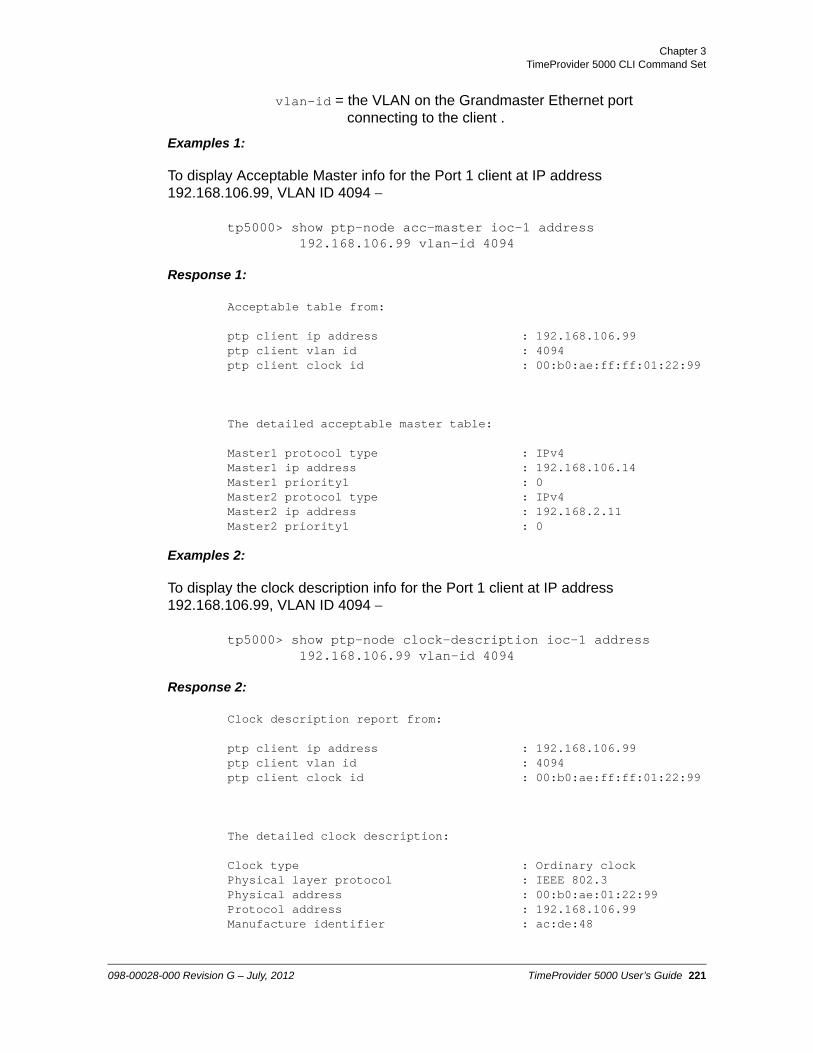
Chapter 3TimeProvider 5000 CLI Command Set
vlan-id = the VLAN on the Grandmaster Ethernet port connecting to the client .
Examples 1:
To display Acceptable Master info for the Port 1 client at IP address 192.168.106.99, VLAN ID 4094
tp5000> show ptp-node acc-master ioc-1 address 192.168.106.99 vlan-id 4094
Response 1:
Acceptable table from:
ptp client ip address : 192.168.106.99ptp client vlan id : 4094ptp client clock id : 00:b0:ae:ff:ff:01:22:99
The detailed acceptable master table:
Master1 protocol type : IPv4Master1 ip address : 192.168.106.14Master1 priority1 : 0Master2 protocol type : IPv4Master2 ip address : 192.168.2.11Master2 priority1 : 0
Examples 2:
To display the clock description info for the Port 1 client at IP address 192.168.106.99, VLAN ID 4094
tp5000> show ptp-node clock-description ioc-1 address192.168.106.99 vlan-id 4094
Response 2:
Clock description report from:
ptp client ip address : 192.168.106.99ptp client vlan id : 4094ptp client clock id : 00:b0:ae:ff:ff:01:22:99
The detailed clock description:
Clock type : Ordinary clockPhysical layer protocol : IEEE 802.3Physical address : 00:b0:ae:01:22:99Protocol address : 192.168.106.99Manufacture identifier : ac:de:48
098-00028-000 Revision G – July, 2012 TimeProvider 5000 User’s Guide 221

Chapter 3 TimeProvider 5000 CLI Command Set
Product description : SYMMETRICOM;TP500;090-03863-01##
Revision data : I0:2.0.2,I1:1.0.28User description :Profile identity : 00:1b:19:01:00:00
Examples 3:
To display the null management info for the Port 1 client at IP address 192.168.106.99, VLAN ID 4094
tp5000> show ptp-node null-mgmt ioc-1 address 192.168.106.99 vlan-id 4094
Response 3:
Null ACK message from:
ptp client ip address : 192.168.106.99ptp client vlan id : 4094ptp client clock id : 00:b0:ae:ff:ff:01:22:99
Examples 4:
To display the status info for the Port 1 client at IP address 192.168.106.99, VLAN ID 4094
tp5000> show ptp-node status ioc-1 address 192.168.106.99 vlan-id 4094
Response 4:
Status report from:
ptp client ip address : 192.168.106.99ptp client vlan id : 4094ptp client clock id : 00:b0:ae:ff:ff:01:22:99
The detailed status:
Current time is : 23:34:52 09/21/2009Current FLL State : Fast FLLFLL State Duration (minutes) : 65Forward Flow Weight (%) : 19.99Forward Flow Transient-free (out of 900 s) : 899Forward Flow Transient-free (out of 3600 s) : 3578Forward Flow Transactions Used (%) : 99.99Forward Flow Operational Min TDEV (ns) : 112.84Forward Flow Min Cluster Width (ns) : 100.00Forward Flow Mode Width (ns) : 100.00Reverse Flow Weight (%) : 80.00Reverse Flow Transient-free (out of 900 s) : 899Reverse Flow Transient-free (out of 3600 s) : 3578Reverse Flow Transactions Used (%) : 99.99
222 TimeProvider 5000 User’s Guide 098-00028-000 Revision G – July, 2012

Chapter 3TimeProvider 5000 CLI Command Set
Reverse Flow Operational Min TDEV (ns) : 114.16Reverse Flow Min Cluster Width (ns) : 100.00Reverse Flow Mode Width (ns) : 2148.00Correction Frequency (ppb) : 11.86Phase correction (ppb) : 0.00Output TDEV Estimate (ns) : 0.00Residual phase error (ns) : 0.00Minimal RTD (us) : 2.14Operational Temperature Max (deg C) : 46.06Operational Temperature Min (deg C) : 45.93Operational Temperature Min (deg C) : 45.935 Minute Temperature Stability (mdeg C) : 216.7560 Minute Temperature Stability (mdeg C) : 481.95Timing Packet Rate GM1 (pkts/s) : 64Timing Packet Rate GM2 (pkts/s) : 0Timing Packet Rate Delay (pkts/s) : 64Observation Interval (min) : 1IPDV Threshold (usec) : 50.000Pacing Factor for Jitter Computation : 16Forward IPDV % Below Threshold : 100.0Forward Maximum IPDV (usec) : 0.103Forward InterPkt Jitter (usec) : 0.027Reverse IPDV % Below Threshold : 100.0Reverse Maximum IPDV (usec) : 0.111Reverse InterPkt Jitter (usec) : 0.028Reference : 192.168.106.14GM1 Flow State : NormalGM2 Flow State : Waiting for GM to respond to signaling
GM1 Clock id : 00:b0:ae:ff:fe:01:90:68
GM2 Clock id : 00:00:00:00:00:00:00:00
Last Firmware Upgrade status: No upgrade since powered
Level : Config and Admin only
set ptp-node
This command allows the user to provide a new Acceptable Master list to the TP500 client found at a specified IP address. If the targeted TP500 is reached, and certain conditions are met, the TP500 client will accept the new acceptable-master list.
The acceptable master list command can also be sent to other clients that support PTP management messages.
This command allows the user to upgrade the firmware on a targeted TP500 client.
This command can also be used to reboot the targeted TP500 client.
Command Syntax:
To set a new Acceptable Master list for the specified PTP port and client (master 2 is optional):
098-00028-000 Revision G – July, 2012 TimeProvider 5000 User’s Guide 223

Chapter 3 TimeProvider 5000 CLI Command Set
set ptp-node acc-master ioc-[y] address <client_ip> [vlan-id <vlan>] master1ip <gm-ip> priority <priority-value> [master2ip <gm-ip> priority <priority-value>]
To upgrade the firmware for the specified client on the specified PTP port:
set ptp-node upgrade ioc-[y] address <client_ip> [vlan-id <vlan>] <filepath> FTP:<server_ip> <user_name>
Where
y= 1|2, the port number on the IOC
<file_path> = path (including filename) to the upgrade file that is to be used once logged onto server
<server_ip> = address of the server where the upgrade file should be found.
<user name>= user name to use for logging onto the server.
This command prompts for the password. The VLAN-ID is optional, needed only if this TP5K is on a VLAN subnet.
To reboot the specified client on the specified PTP port:
set ptp-node reboot ioc-[y] address <client_ip> [vlan-id <vlan>]
Examples 1:
To set the Acceptable Master info for the Port 1 client at IP address 192.168.5.177, VLAN ID 15, Master1 IP address 192.168.5.15 and priority value of 0, with no Master2
tp5000> set ptp-node acc-master ioc-1 address 192.168.5.177 vlan-id 15 master1ip 192.168.5.15 priority 0
Examples 2:
To set the Acceptable Master info for the Port 1 client at IP address 192.168.5.177, no VLAN, Master1 IP address 192.168.5.15 priority 0, Master2 IP address 192.168.5.20 and priority value of 0
tp5000> set ptp-node acc-master ioc-1 address 192.168.5.177 vlan-id 15 master1ip 192.168.5.15 priority 0 master2ip 192.168.5.20 priority 0
Examples 3:
Note: A priority value of 0 causes the PTP client to use the priority value sent from the grandmaster, rather than overriding the value.
224 TimeProvider 5000 User’s Guide 098-00028-000 Revision G – July, 2012

Chapter 3TimeProvider 5000 CLI Command Set
For a client on port 1, client IP address of 192.168.5.64, an FTP server with IP address 192.168.5.100, a user name of “user1”, and an upgrade file path of “upgradefiles\ver2.bin”
tp5000> set ptp-node upgrade ioc-1 address 192.168.5.64 upgradefiles\ver2.bin ftp:192.168.5.100 user1
Response 3:
Password:
Examples 4:
To reboot the port 1 client at IP address 192.168.5.64, no VLAN
tp5000> set ptp-node reboot ioc-1 address 192.168.5.64
Level : Config and Admin only
098-00028-000 Revision G – July, 2012 TimeProvider 5000 User’s Guide 225

Chapter 3 TimeProvider 5000 CLI Command Set
show ptp-probe
This command is used to begin PTP packet measurements. This command can also be used to display the Probe configuration, which includes Grandmaster Clock ID, IP address and VLAN (if applicable), interval rate, and lease duration.
Command Syntax:
To display the probe configuration data:
show ptp-probe config ioc1-[y]
To begin gathering data with the probe:
show ptp-probe data ioc1-[y]
where
y= 1|2, the port number on IOC1
To stop gathering data with the probe, press the Enter key.
Example 1:
To display the configuration data of the Probe on port 2
tp5000> show ptp-probe config ioc1-2
Example 2:
To display the test data from port 1 of the Probe
tp5000> show ptp-probe data ioc-1
Response :
F,00011,1229541029,099868364,1229541029,099881920,0000000000,B,00011,1229541029,562553320,1229541029,562539700,0000000000,F,00012,1229541030,099868364,1229541030,099881776,0000000000,B,00012,1229541030,562553320,1229541030,562539700,0000000000,F,00013,1229541031,099868364,1229541031,099881936,0000000000,B,00013,1229541031,562553288,1229541031,562539700,0000000000,F,00014,1229541032,099868364,1229541032,099881776,0000000000,B,00014,1229541032,562553288,1229541032,562539700,0000000000,
Level : User, Config and Admin
Note: The Probe option must be purchased to enable the functionality of all “ptp-probe” commands.
226 TimeProvider 5000 User’s Guide 098-00028-000 Revision G – July, 2012

Chapter 3TimeProvider 5000 CLI Command Set
set ptp-probe
Use this command with a TP 5000 that is configured in Probe mode to specify the Grandmaster IP address and Clock ID. This command is used to set the PTP profile, interval rate for Sync and Delay Requests and the lease duration for the specified Probe IOC card and port. This command is also used to restart the specified Probe IOC card and port.
The PTP probe mode supports three profiles:
Default: Multicast Layer 3 of 7-layer model
Ethernet-Default: Multicast Layer 2 of 7-layer model
Telecom-2008: Unicast.
Command Syntax:
To set the IP address and Clock ID for the Grandmaster being tested by the Probe:
set ptp-probe ioc1-[y] active-probe gm-clock-id <clock-id> gm-ip <addr> [vlan-id <vlan>]
where
y = 1|2, the port number on the IOC<clock-id> is in the form “xx:xx:xx:xx:xx:xx:xx:xx”
To set the PTP profile for the Probe:
set ptp-probe ioc1-[y] active-probe profile {default | telecom-2008 | Ethernet-default}
where
y = 1|2, the port number on the IOC<clock-id> is in the form “xx:xx:xx:xx:xx:xx:xx:xx”
To set the interval rate for Sync and Delay Requests from the Probe:
set ptp-probe ioc1-y active-probe interval <int-value>
The interval is 2z seconds, where z is <int-value>.
To set the maximum lease duration for the Probe:
Note: The PTP probe option must be purchased to enable the functionality of all “ptp-probe” commands.
Note: PTP probe is not supported through SNMP..
098-00028-000 Revision G – July, 2012 TimeProvider 5000 User’s Guide 227

Chapter 3 TimeProvider 5000 CLI Command Set
set ptp-probe ioc1-[y] active-probe duration <dur-value>
Example 1:
For a Grandmaster Clock ID of 00:B0:AE:FF:FE:00:00:06, Grandmaster IP address of 192.168.1.11, and probe VLAN ID of 35:
tp5000>set ptp-probe ioc1-1 active-probe gm-clock-id 00:B0:AE:FF:FE:00:00:06 gm-ip 192.168.1.11 vlan-id 35
For a Grandmaster Clock ID of 00:B0:AE:FF:FE:00:00:06, GrandmasterIP address of 192.168.1.11, and no VLAN:
tp5000> set ptp-probe ioc1-1 active-probe gm-clock-id 00:B0:AE:FF:FE:00:00:06 gm-ip 192.168.1.11 <enter>
Example 2:
For an interval of 0.25 seconds ( -2 ) on Port 1 of IOC1:
tp5000> set ptp-probe ioc1-1 active-probe interval -2
Example 3:
For a duration of 500 seconds on Port 1 of IOC1:
tp5000> set ptp-probe ioc1-1 active-probe duration 500
Level : Config and Admin only
228 TimeProvider 5000 User’s Guide 098-00028-000 Revision G – July, 2012

Chapter 3TimeProvider 5000 CLI Command Set
show ptp status
Use these commands to display the PTP GrandMaster status for the selected port.
Command Syntax:
show ptp status { ioc-1 | ioc-2 | exp[0-9] port <1-16>}
Example 1:
tp5000> show ptp status ioc-1
Response 1:
Grandmaster status information:
Port enabled : yesClock Id : 00:B0:AE:FF:FE:01:CC:44, 1Profile : defaultPort state : masterClock class : 7Clock accuracy : within 10usTimescale : PTPNum clients : 0Client load : 0%
Example 2:
To show the PTP status of the PTP port in expansion shelf 9 (id=exp8), port 15
tp5000> show ptp status exp8 port 15
Response 2:
Grandmaster status information:
Port enabled : yesClock Id : 00:B0:AE:FF:FE:01:32:70, 15Profile : ethernet-defaultPort state : master [passive | listening |disabled]Clock class : locked to referenceClock accuracy : within 100nsTimescale : ptpNum clients : 1Client load : 0%
Level : User, Config, and Admin
098-00028-000 Revision G – July, 2012 TimeProvider 5000 User’s Guide 229

Chapter 3 TimeProvider 5000 CLI Command Set
reboot
This command restarts one or more of the modules. Using this command can cause a loss of outputs.
Command Syntax:
reboot {system|imc|ioc1|ioc2|exp[0-9]}
Remarks: Selecting system restarts all system modules and expansion shelves. Selecting system, or the only IOC, or an expansion shelf disrupts the system outputs.
Example 1:
tp5000> reboot imc
Response 1:
The system is going down NOW!Sending SIGTERM to all processes
Sending SIGKILL to all processesRequesting system rebootRestarting system.
U-Boot 1.1.6 (Oct 23 2008 - 13:17:59) MPC83XX
Symmetricom Time Provider 5000 (TP5000) IMC
Clock configuration:Coherent System Bus: 166 MHzCore: 333 MHzLocal Bus Controller: 166 MHzLocal Bus: 41 MHzDDR: 333 MHzSEC: 55 MHzI2C1: 166 MHzI2C2: 166 MHzTSEC1: 166 MHzTSEC2: 166 MHzUSB MPH: 0 MHzUSB DR: 55 MHz
CPU: MPC8313E, Rev: 10 at 333.333 MHzINFO: Initializing IOMEM for regset 0DRAM: 256 MBNAND: 256 MiBUsing default environment........................................
Symmetricom tp5000_imc
230 TimeProvider 5000 User’s Guide 098-00028-000 Revision G – July, 2012

Chapter 3TimeProvider 5000 CLI Command Set
login:
Example 2:
To Reboot IOC1
tp5000> reboot ioc1
Response 2:
NO MESSAGE.NO INDICATION.LED ALARM GREEN BLINKING
tp5000>
Example 3:
For defective IOC or no IOC -
tp5000> reboot ioc2
Response 3:
ErrorIOC is not present.
tp5000>
Example 4:
To reboot expansion shelf 1 (module id=exp0), which is PTP/SyncE -
tp5000> reboot exp0
Response 4:
<No response message>
tp5000>
Example 5:
To reboot expansion shelf 6 (module id=exp5), which is E1/1PPS+TOD -:
tp5000> reboot exp5
Response 5:
<No response message>
tp5000>
098-00028-000 Revision G – July, 2012 TimeProvider 5000 User’s Guide 231

Chapter 3 TimeProvider 5000 CLI Command Set
Level : Admin only
232 TimeProvider 5000 User’s Guide 098-00028-000 Revision G – July, 2012

Chapter 3TimeProvider 5000 CLI Command Set
show redundancy
This command displays the IOC redundancy configuration: Port Bonding and IOC Module.
Command Syntax:
To display the port redundancy configuration for the specified IOC module:
show redundancy port ioc1
To display the redundancy port status:
show redundancy active-port
Example 1:
tp5000> show redundancy port ioc1
Response 1:
Port redundancy : enabled
Example 2:
tp5000> show redundancy active-port
Response 2:
IOC active port: eth1
Response 2a:
If redundancy is disabled, the response to this command is:
IOC active port : no active port, redundancy disabled
Level : User, Config, and Admin
set redundancy
Use this command to provision the redundancy configuration for the Ethernet ports on the IOC module.
Command Syntax:
set redundancy port ioc1 {enable|disable}set redundancy active-port ioc-[y]
where
098-00028-000 Revision G – July, 2012 TimeProvider 5000 User’s Guide 233

Chapter 3 TimeProvider 5000 CLI Command Set
y= 1|2, the port number on the active IOC module
Example 1:
To enable port redundancy on IOC1 module
tp5000> set redundancy port ioc1 enable
Example 2:
To set Port 1 as the active port in the redundancy configuration
tp5000> set redundancy active-port ioc-1
Level : Config and Admin only
234 TimeProvider 5000 User’s Guide 098-00028-000 Revision G – July, 2012

Chapter 3TimeProvider 5000 CLI Command Set
show ref
Use this command to display the system's reference mode and manual input reference.
Command Syntax:
show ref
Example:
tp5000> show ref
Response:
Reference Info
-------------------------------------------------------------------------------| Reference | Ref | Priority | PQL | PQL Config | PQL Input | Reference || | State | | State | Value | Value | Status ||-----------|-------|----------|-------|------------|-----------|-------------|| GNSS |enable | 1 |disable| 1 | 1 |disqualified ||...........|.......|..........|.......|............|...........|.............|| GPS |enable | 2 |disable| 1 | 1 |selected ||...........|.......|..........|.......|............|...........|.............|| PPS-TOD-1 |enable | 3 |disable| 1 | 1 |disqualified ||...........|.......|..........|.......|............|...........|.............|| PPS-TOD-2 |enable | 4 |disable| 1 | 1 |disqualified ||...........|.......|..........|.......|............|...........|.............|| Input-1 |enable | 7 |disable| 3 | 15 |disqualified ||...........|.......|..........|.......|............|...........|.............|| Input-2 |enable | 8 |disable| 3 | 15 |disqualified ||...........|.......|..........|.......|............|...........|.............|
Reference Mode - timeReference Criteria - priority
Level : User, Config, and Admin
098-00028-000 Revision G – July, 2012 TimeProvider 5000 User’s Guide 235

Chapter 3 TimeProvider 5000 CLI Command Set
set ref
Use this command to provision the system's reference mode and reference selection criteria. It allows the user to select the reference mode as timing mode or frequency mode. In Timing Mode, timing reference will have higher priority than frequency reference. If all timing references are not available (disabled or disqualified), the frequency reference will be used to assist timing holdover. The Timing Reference includes GNSS (GPS/Beidou) inputs and TOD/1PPS inputs. In Frequency Mode, both timing reference and frequency reference can be used for frequency lockup. The system will not do phase lockup in frequency mode even if there is valid timing reference. The frequency references are the E1/T1 inputs.
When switching reference mode, the system selects the new reference based on REF CRITERIA. When Ref Criteria is set to PRIORITY, the system selects the reference based on the priority setting of the inputs. When Ref Criteria is set to SSM, the system selects the reference based on the SSM (received or provisioned) of the inputs.
Command Syntax:
To set the criteria for how to switch references:
set ref criteria {priority | ssm}
To set the reference to timing mode or frequency mode:
set ref mode {time | frequency}
Note: The reference criterion MANUAL is no longer supported. Only PRIORITY and SSM are supported for reference selection.
Manual selection of a reference input can be done by disabling all reference input ports except the desired one.
The “set ref override” command is no longer supported.
Note: Command “set ref mode time” has the same meaning as “set tod-source GPS” and “set ref mode frequency” has the same meaning as “set tod-source sys”. See set tod-source command.
Note: Commands to change the reference mode should not be repeatedly sent to the TP5000, especially before the reference has been qualified.
236 TimeProvider 5000 User’s Guide 098-00028-000 Revision G – July, 2012

Chapter 3TimeProvider 5000 CLI Command Set
Example 1:
To set the reference mode to time
tp5000> set ref mode time
Example 2:
To set the reference mode to frequency
tp5000> set ref mode frequency
Example 3:
To set the reference to be selected based on the priority setting
tp5000> set ref criteria priority
Level : Config and Admin only
098-00028-000 Revision G – July, 2012 TimeProvider 5000 User’s Guide 237

Chapter 3 TimeProvider 5000 CLI Command Set
show remote-syslog
This command displays the remote syslog server that log messages are sent to from the TimeProvider 5000.
Command Syntax:
show remote-syslog
Example:
tp5000> show remote-syslog
Response:
State - disableRemote Address - 0.0.0.0
Level : User, Config, and Admin
set remote-syslog
This command is used to configure a remote syslog server to receive log messages from the TimeProvider 5000.
Command Syntax:
set remote-syslog {enable <host-addr>|disable}
}
Example:
To enable a remote syslog server at IP address 192.168.5.141
tp5000> set remote-syslog enable 192.168.5.141
Level : Config and Admin only
238 TimeProvider 5000 User’s Guide 098-00028-000 Revision G – July, 2012

Chapter 3TimeProvider 5000 CLI Command Set
show snmp
Use these commands to display the SNMP Manager assigned to the agent, all assigned users (username only), and the SNMP trap version and SNMP trap user.
Command Syntax:
To display the SNMP manager assignment:
show snmp manager
To display the SNMPv3 user configuration:
show snmp user
To display the SNMP TRAP user information (user names only):
show snmp trapuser
To display the SNMP v2-community information:
show snmp v2-community
To display the SNMP TRAP version information:
show snmp trapversion
To display the SNMP V2 state:
show snmp state-v2
To display the SNMP trap MIB has been selected:
show snmp trap-mib
To display which SNMP MIB version, 1.2 or 2.0, has been selected:
show snmp sys-obj-mib
Example 1:
tp5000> show snmp manager
Response 1:
-----------------------------------------------------------------------------|Index|Manager ID |Manager Addr |Engine ID ||-----|---------------|--------------------|--------------------------------||1 |m192.168.5.187 |192.168.5.187 |0x63000000a1c0a805bb ||.....|...............|....................|................................||2 |m192.168.5.144 |192.168.5.144 |0x0123456789010384 ||.....|...............|....................|................................||3 |m192.168.5.171 |192.168.5.171 |0x63000000a1c0a805bb ||-----------------------------------------------------------------------------
Example 2:
tp5000> show snmp user
098-00028-000 Revision G – July, 2012 TimeProvider 5000 User’s Guide 239

Chapter 3 TimeProvider 5000 CLI Command Set
Response 2:
--------------------------------------------------------------------------|Index|User Name |User Type |Auth. Key |Priv. Key ||-----|--------------------|-------------|---------------|---------------||1 |test |snmpnoauth |********** |********** ||.....|....................|.............|...............|...............||2 |harsha |snmpshades |********** |********** |--------------------------------------------------------------------------
Example 3:
tp5000> show snmp trapuser
Response 3:
No SNMP trap user configured.
Example 4:
tp5000> show snmp v2-community
Response 4:
-----------------------------------------|Index|Community Name |Access Level||-----|--------------------|------------||1 |test |readwrite ||.....|....................|............||2 |testteam |readwrite |-----------------------------------------
Example 5:
tp5000> show snmp trapversion
Response 5:
Trap version - v2c
Example 6:
tp5000> show snmp state-v2
Response 6:
SNMP v2 state - enable
Example 7:
tp5000> show snmp trap-mib
Response 7:
SNMP Trap MIB Version - 2.0
240 TimeProvider 5000 User’s Guide 098-00028-000 Revision G – July, 2012

Chapter 3TimeProvider 5000 CLI Command Set
Example 8:
tp5000> show snmp sys-obj-mib
Response 8:
SNMP System MIB Object ID Version - 2.0
Level : User, Config, and Admin
set snmp
Use this command to provision the SNMP v2 state, trap version, user assignment, manager assignment, and trapuser and v2 community assignments.
Command Syntax:
To add an SNMP user or trapuser:
set snmp add {user | trapuser} <name> securelvl {noauth | auth | priv}
To add an SNMP v2-community:
set snmp add v2-community <name> secureLvl {read-only| read-write}
To add an SNMP manager:
set snmp add manager <ip-address> engineid <engine-id>
To delete an SNMP user, trapuser, or v2-community:
set snmp delete {user | trapuser | v2-community} <name>
To delete an SNMP manager:
set snmp delete manager <ip-address>
To set the SNMP trap version to either v2c or v3:
set snmp trapversion {2|3}
Role Max Number
SNMP User 10
Trapuser 3
Manager 3
v2 Community 10
098-00028-000 Revision G – July, 2012 TimeProvider 5000 User’s Guide 241

Chapter 3 TimeProvider 5000 CLI Command Set
To provision the state of SNMP v2 communities:
set snmp state-v2 {enable | disable}
To set the SNMP sys-obj MIB version to either 1.2 or 2.0:
set snmp sys-obj-mib {1.2 | 2.0}
To set the SNMP trap MIB version to either 1.2 or 2.0:
set snmp trap-mib {1.2 | 2.0}
Example 1:
To add SNMP user named “maynard”, with a security level of “priv”:
tp5000> set snmp add user maynard securelvl priv
Response 1:
For security level of priv, the TP5000 will prompt for:
Authentication protocol (MD5 or SHA):Authentication key [Only chars {a-z,A-Z,0-9,! ( )- _ . ? ~ * @ ^ + = : / %} are accepted] :Privacy protocol (DES or AES):Privacy key [Only chars {a-z,A-Z,0-9,! ( )- _ . ? ~ * @ ^ + = : / %} are accepted]:
If the security level is auth, the TP5000 will prompt for:
authkey <authkey-value>
authtype {MD5 | SHA}
Example 2:
To add SNMP v2-community named “groupv2”, with a security level of read-write:
tp5000> set snmp add v2-community groupv2 securelvl read-write
Example 3:
To add SNMP manager with the IP address 192.168.5.177 and engine ID of 0x12345678901234:
set snmp add manager 192.168.5.177 engineid 0x12345678901234
Example 4:
To delete SNMP trap user named “george3”:
242 TimeProvider 5000 User’s Guide 098-00028-000 Revision G – July, 2012

Chapter 3TimeProvider 5000 CLI Command Set
set snmp delete trapuser george3
Example 5:
To delete SNMP manager at IP address 192.168.5.177:
tp5000> set snmp delete manager 192.168.5.177
Example 6:
To set the trap version to SNMP v3:
tp5000> set snmp trapversion 3
Example 7:
To enable SNMP v2 on the TP5000:
tp5000> set snmp state-v2 enable
Example 8:
To set the sys-obj MIB to version 2.0:
tp5000> set snmp sys-obj-mib 2.0
Example 9:
To set the trap MIB to version 2.0:
tp5000> set snmp trap-mib 2.0
Level : Admin only
098-00028-000 Revision G – July, 2012 TimeProvider 5000 User’s Guide 243

Chapter 3 TimeProvider 5000 CLI Command Set
show ssm-option
Use this command to display whether the E1 or T1 sync network option is selected, as defined in G.781, for the IOCs and expansion shelves.
Command Syntax:
show ssm-option
Example:
tp5000> show ssm-option
Response:
Module or Shelf SSM Option -------------------------------------IOC ITU option I EXP0 ITU option I EXP1 ITU option I EXP3 ITU option I
set ssm-option
Use this command to select either E1 or T1 sync network options as defined in G.781:
Command Syntax:
set ssm-option {all | ioc1 | exp<0-9>} {option1 | option2}
Example:
To set the ssm-option for all to option1
tp5000> set ssm-option all option1
Note: The ssm-option only applies to syncE and the G.8265.1 profile of PTP.
244 TimeProvider 5000 User’s Guide 098-00028-000 Revision G – July, 2012

Chapter 3TimeProvider 5000 CLI Command Set
show status
Use this command to display the following system status information:
Assigned System Name
Warm-up Status
– Current Stage
– Number of Stages
– Time in Current Stage While in Warmup
Uptime For The IMC
System Date And Time
Number Of Standing System Alarms
Uptime for each IOC
State of each IOC
Currently Selected ToD Source
Reference Input
Servo Control Status For The Active IOC Module
PTP Packet Service: GrandMaster, NTP Server, or PTP Probe
Phase Offset Value (Valid in fast-lock and normal states, for GPS mode)
Command Syntax:
show status
Example 1:
To show status for the main shelf
tp5000> show status
Response 1:
System name : TP5000IMC time : 2010-03-08 20:33:30IMC uptime : 7 days 2 hrs 18 minsIOC1 warmup status : complete (total 1651 secs)IOC1 state : activeIOC1 uptime : 7 days 2 hrs 18 minsIOC2 warmup status : n/aIOC2 state : card not presentIOC2 uptime : card not presentReference Mode : time
098-00028-000 Revision G – July, 2012 TimeProvider 5000 User’s Guide 245

Chapter 3 TimeProvider 5000 CLI Command Set
Current reference input : GPSClock status : normal trackPhase Offset : 0 nsPacket service eth1 : ptp grandmasterPacket service eth2 : ptp grandmasterActive alarms : 1Exp connections : 1, 3, 6, 9
Example 2:
To display the status of PTP/SyncE expansion shelf 8 (id=exp7)
tp5000> show status exp7
Response 2:
Expansion shelf: PTP-SyncEShelf time: 2010-03-08 20:33:30Shelf uptime: 7 days 2 hrs 18 minsMain Clock status: normal trackShelf clock status: normal trackCombined Clock status: normal trackPhase Offset: 0 nsPacket Service: ptp grandmasterSyncE output PQL: 2
Example 3:
To display the status of E1/1PPS+TOD expansion shelf 3 (id=exp2)
tp5000> show status exp2
Response 3:
Expansion shelf: E1-TODshelf time : 2010-03-08 20:33:30shelf uptime : 7 days 2 hrs 18 minsMain Clock status : normal trackShelf clock status: normal trackCombined Clock status: normal trackPhase Offset : 0 nsE1 output PQL: 2
Note: the value of "SyncE output PQL" is the PQL level defined in PQL-SSM table. See response of command "SHOW PQL-SSM" for the descriptions of the PQL level.
Note: The value of "E1 output PQL" is the PQL level defined in PQL-SSM table. See response of command "SHOW PQL-SSM" for the descriptions of the PQL level.
246 TimeProvider 5000 User’s Guide 098-00028-000 Revision G – July, 2012

Chapter 3TimeProvider 5000 CLI Command Set
Remarks :See Table 3-4 below for IOC Clock Status descriptions.
Level : User, Config, and Admin
Table 3-4. IOC Clock Status
IOC Clock Status
DescriptionPossible Next
State
Conditions Required for Next Transition
State
Warmup This IOC is warming up. Freerun Ref mode = frequencyWarm-up complete
Fast-track Ref mode = timeGPS qualifiedWarm-up complete
Freerun This IOC is operating without a reference
Freerun Ref mode changed from frequency to time
Fast-track Input becomes qualified
Fast-track This IOC has a qualified input and clock is stabilizing.
Bridging This IOC no longer has a qualified input.
Normal-track Clock stabilized
Normal This IOC has a qualified input and meets all specifications.
Fast-track Clock not stabilized adequately
Bridging This IOC no longer has a qualified input.
Bridging This IOC no longer has a qualified reference, but remains operating within specification associated with normal_track operation.
Holdover Bridging time exceeded
Fast-track Input reference re-qualified in less than bridging time.
Holdover This IOC no longer has a qualified reference
Fast-track Input becomes qualified
See Note below.
Fail Hardware failure detected on this IOC
none N/A
098-00028-000 Revision G – July, 2012 TimeProvider 5000 User’s Guide 247

Chapter 3 TimeProvider 5000 CLI Command Set
show synce
Use this command to display SyncE status, configuration, and Ethernet Synchronization Messaging Channel (ESMC) state for the specified expansion shelf.
Command Syntax:
To display the SyncE status for the specified expansion shelf:
show synce status exp[0-9]
To display the SyncE configuration parameters for the specified expansion shelf:
show synce config exp[0-9]
Example 1:
To display the SyncE status for expansion shelf 10 (id=exp9):
tp5000> show synce status exp9
Response 1:
tp5000> show synce status exp0
SyncE Status
--------------------------------------------------------------------------
| Port ID | Direction | Ethernet Mode | ESMC Status | Rx PQL | Tx PQL ||---------|-----------|------------------|-------------|--------|--------|| Port1 | output | asynchronous | off | 0x0f | 0x0f ||.........|...........|..................|.............|........|........|| Port2 | output | asynchronous | off | 0x0f | 0x0f ||.........|...........|..................|.............|........|........|| Port3 | output | asynchronous | off | 0x0f | 0x0f ||.........|...........|..................|.............|........|........|| Port4 | output | asynchronous | off | 0x0f | 0x0f ||.........|...........|..................|.............|........|........|| Port5 | output | asynchronous | off | 0x0f | 0x0f ||.........|...........|..................|.............|........|........|| Port6 | output | asynchronous | off | 0x0f | 0x0f ||.........|...........|..................|.............|........|........|| Port7 | output | asynchronous | off | 0x0f | 0x0f ||.........|...........|..................|.............|........|........|| Port8 | output | asynchronous | off | 0x0f | 0x0f ||.........|...........|..................|.............|........|........|| Port9 | output | asynchronous | off | 0x0f | 0x0f ||.........|...........|..................|.............|........|........|| Port10 | output | asynchronous | off | 0x0f | 0x0f |
248 TimeProvider 5000 User’s Guide 098-00028-000 Revision G – July, 2012

Chapter 3TimeProvider 5000 CLI Command Set
|.........|...........|..................|.............|........|........|| Port11 | output | asynchronous | off | 0x0f | 0x0f ||.........|...........|..................|.............|........|........|| Port12 | output | asynchronous | off | 0x0f | 0x0f ||.........|...........|..................|.............|........|........|| Port13 | output | asynchronous | off | 0x0f | 0x0f ||.........|...........|..................|.............|........|........|| Port14 | output | asynchronous | off | 0x0f | 0x0f ||.........|...........|..................|.............|........|........|| Port15 | output | asynchronous | off | 0x0f | 0x0f ||.........|...........|..................|.............|........|........|| Port16 | output | asynchronous | off | 0x0f | 0x0f ||.........|...........|..................|.............|........|........|
Example 2:
To display the SyncE configuration for expansion shelf 10 (id=exp9):
tp5000> show synce config exp9
Response 2:
SyncE Configuration
-------------------------------------------------------------------------------| Port ID | Direction | ESMC State | QL State | Output QL Mode | Forced Input || | | | | | QL Value ||---------|-----------|------------|----------|----------------|--------------|| Port1 | output | disable | enable | unidirectional | n/a ||.........|...........|............|..........|................|..............|| Port2 | output | disable | enable | unidirectional | n/a ||.........|...........|............|..........|................|..............|| Port3 | output | disable | enable | unidirectional | n/a ||.........|...........|............|..........|................|..............|| Port4 | output | disable | enable | unidirectional | n/a ||.........|...........|............|..........|................|..............|| Port5 | output | disable | enable | unidirectional | n/a ||.........|...........|............|..........|................|..............|| Port6 | output | disable | enable | unidirectional | n/a ||.........|...........|............|..........|................|..............|| Port7 | output | disable | enable | unidirectional | n/a ||.........|...........|............|..........|................|..............|| Port8 | output | disable | enable | unidirectional | n/a ||.........|...........|............|..........|................|..............|| Port9 | output | disable | enable | unidirectional | n/a ||.........|...........|............|..........|................|..............|| Port10 | output | disable | enable | unidirectional | n/a ||.........|...........|............|..........|................|..............|| Port11 | output | disable | enable | unidirectional | n/a ||.........|...........|............|..........|................|..............|| Port12 | output | disable | enable | unidirectional | n/a ||.........|...........|............|..........|................|..............|| Port13 | output | disable | enable | unidirectional | n/a ||.........|...........|............|..........|................|..............|| Port14 | output | disable | enable | unidirectional | n/a |
098-00028-000 Revision G – July, 2012 TimeProvider 5000 User’s Guide 249
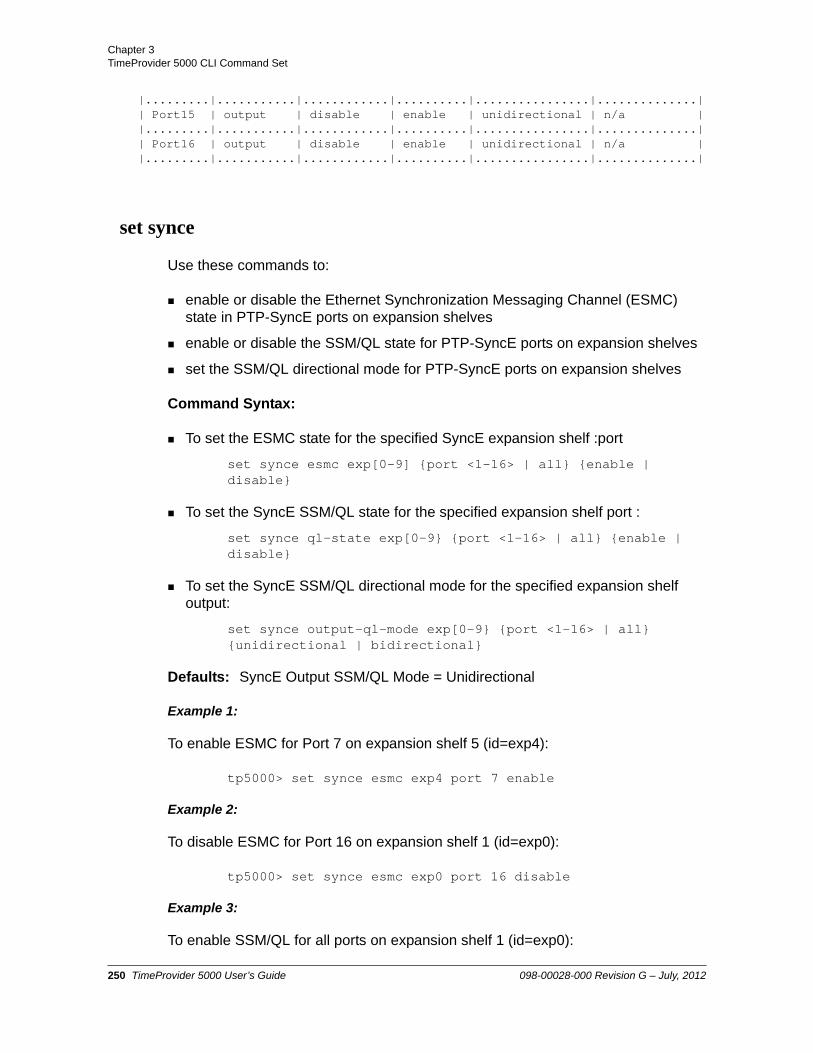
Chapter 3 TimeProvider 5000 CLI Command Set
|.........|...........|............|..........|................|..............|| Port15 | output | disable | enable | unidirectional | n/a ||.........|...........|............|..........|................|..............|| Port16 | output | disable | enable | unidirectional | n/a ||.........|...........|............|..........|................|..............|
set synce
Use these commands to:
enable or disable the Ethernet Synchronization Messaging Channel (ESMC) state in PTP-SyncE ports on expansion shelves
enable or disable the SSM/QL state for PTP-SyncE ports on expansion shelves
set the SSM/QL directional mode for PTP-SyncE ports on expansion shelves
Command Syntax:
To set the ESMC state for the specified SyncE expansion shelf :port
set synce esmc exp[0-9] {port <1-16> | all} {enable | disable}
To set the SyncE SSM/QL state for the specified expansion shelf port :
set synce ql-state exp[0-9} {port <1-16> | all} {enable | disable}
To set the SyncE SSM/QL directional mode for the specified expansion shelf output:
set synce output-ql-mode exp[0-9} {port <1-16> | all} {unidirectional | bidirectional}
Defaults: SyncE Output SSM/QL Mode = Unidirectional
Example 1:
To enable ESMC for Port 7 on expansion shelf 5 (id=exp4):
tp5000> set synce esmc exp4 port 7 enable
Example 2:
To disable ESMC for Port 16 on expansion shelf 1 (id=exp0):
tp5000> set synce esmc exp0 port 16 disable
Example 3:
To enable SSM/QL for all ports on expansion shelf 1 (id=exp0):
250 TimeProvider 5000 User’s Guide 098-00028-000 Revision G – July, 2012

Chapter 3TimeProvider 5000 CLI Command Set
tp5000> set synce ql-state exp0 all enable
Example 4:
To set the SSM/QL directional mode to bidirectional for all ports on expansion shelf 1 (id=exp0):
tp5000> set synce output-ql-mode exp0 all bidirectional
Remarks: This command only applies to PTP/SyncE expansion shelves.
Level : Config and Admin only
098-00028-000 Revision G – July, 2012 TimeProvider 5000 User’s Guide 251

Chapter 3 TimeProvider 5000 CLI Command Set
set-timeout
This command sets the inactivity timeout to the defined time interval, in seconds. This setting is only used for the current session.
Command Syntax:
set-timeout
Range: 0 to 86400 seconds
Default: 0 seconds
Example:
tp5000> set-timeout
Response:
(Prompt for value)
Timeout ( 0 - 86400 sec): 1800
1800 sec timeout set successfully
Level : User, Config, and Admin
show-timeout
This command displays the inactivity timeout to the defined time interval, in seconds.
Command Syntax:
show-timeout
Example:
tp5000> show-timeout
Response:
The current session timeout - 900 sec
Level : User, Config, and Admin
252 TimeProvider 5000 User’s Guide 098-00028-000 Revision G – July, 2012

Chapter 3TimeProvider 5000 CLI Command Set
show tod-source
This command displays the Time of Day Source.
Command Syntax:
show tod-source
Example:
tp5000> show tod-source
Response:
ToD Source - gps
Level : User, Config, and Admin
set tod-source
Use this command to provision the ToD Source to be provided by GPS or the System.
The set ref mode command replaces the set tod-source command. The set tod-source command is supported for backward-compatibility.
Command Syntax:
set tod-source {gps|sys}
Example 1:
tp5000> set tod-source gps
Remarks: Command set tod-source GPS has the same meaning as set ref mode time and set tod-source sys has the same meaning as set ref mode frequency. See Set REF command.
Level : Config and Admin only
Note: Setting the Time of Day source to GPS with the set tod-source command will also set the input reference port state to Disable.
Note: Commands to change the reference mode should not be repeatedly sent to the TP5000, especially before the reference has been qualified.
098-00028-000 Revision G – July, 2012 TimeProvider 5000 User’s Guide 253

Chapter 3 TimeProvider 5000 CLI Command Set
sync tod-source
Use this command to force the system to synchronize the phase and time to the current reference. This command is required to clear alarmID 8 (manual sync IOC to IMC required).
Command Syntax:
sync tod-source now
Example:
tp5000> sync tod-source now
Remarks: This command can cause jitter or jump of 1PPS output.
Level : Config and Admin only
254 TimeProvider 5000 User’s Guide 098-00028-000 Revision G – July, 2012

Chapter 3TimeProvider 5000 CLI Command Set
upgrade
Use this command to upgrade the specified modules firmware with the specified filename. If the IP address, username, and password is provided, the system will FTP the filename from the specified server (IP or name) and then upgrade the specified module.
Command Syntax:
upgrade {imc | ioc1 | ioc2 | exp[0-9]} <filepath> [ftp: | sftp:] <ftp-ip-address> <username>
Remarks: Firmware upgrades will not be implemented until the specified module is rebooted.
Example 1:
To upgrade the IMC using the upgrade file path of “/symm/tp5000/current_imc_upd”, FTP server IP address 192.168.5.56, and a user name of “bob321”.
tp5000> upgrade imc /symm/tp5000/current_imc_upd ftp:192.168.5.56 bob321
Response 1:
Password:
Upgrade of imc is in progress
Note: The FTP firewall is set to “Block” by default. Use the following command to set the IMC firewall to “Allow” for ftp communications:
set firewall imc ftp allow
Note: The TimeProvider 5000 only supports active FTP; it does not support passive (PASV) mode.
Note: For SFTP, both the SFTP and SSH firewalls must be set to “Allow”. They are both set to “Allow” by default.
Note: If an SFTP server is used, the protocol does not need to be included with the address.
ftp:192.168.5.64[sftp:]192.168.5.64
098-00028-000 Revision G – July, 2012 TimeProvider 5000 User’s Guide 255

Chapter 3 TimeProvider 5000 CLI Command Set
!!!!!!!!!!!!!!!!!!!!!!!!!!!!!!!!!!!!!!!!!!!!!!!!!!!!!!!!!!!!!!!!!!!!!!!!!!!!!!!!!!!!!!!!!!!!!!!!!!!!!!!!!!!!!!!!!!!!!!!!!!!!!!!!!!!!!!!!!!!!!!!!!!!!!!!!!!!!!!!!!!!!!
Upgrade of imc is successfully completed
Example 2:
To upgrade the IMC using the upgrade file path of “/symm/tp5000/current_imc_upd”, SFTP server IP address 192.168.5.57, and a user name of “bob321”.
tp5000> upgrade imc /symm/tp5000/current_imc_upd sftp:192.168.5.57 bob321
or
tp5000> upgrade imc /symm/tp5000/current_imc_upd 192.168.5.57 bob321
Response 2:
See Response 1.
Example 3:
To upgrade the PTP-SyncE expansion shelf ID=4 using the upgrade file path of "/symm/tp5000/current_ptp_exp_upd", FTP server IP address 192.168.5.56, and a user name of "bob321", Password: "bob123!"
tp5000> upgrade exp4 /symm/tp5000/current_ptp_exp_upd ftp:192.168.5.56 bob321
Response 3:
Password: bob123! <enter>
Upgrade of exp4 is in progress
!!!!!!!!!!!!!!!!!!!!!!!!!!!!!!!!!!!!!!!!!!!!!!!!!!!!!!!!!!!!!!!!!!!!!!!!!!!!!!!!!!!!!!!!!!!!!!!!!!!!!!!!!!!!!!!!!!!!!!!!!!!!!!!!!!!!!!!!!!!!!!!!!!!!!!!!!!!!!!!!!!!!!
Upgrade of exp4 is successfully completed
Example 4:
To upgrade the E1-TOD expansion shelf ID=0 using the upgrade file path of “/symm/tp5000/current_e1_exp_upd", FTP server IP address 192.168.5.56, and a user name of "bob321". Password: "bob123!"
256 TimeProvider 5000 User’s Guide 098-00028-000 Revision G – July, 2012

Chapter 3TimeProvider 5000 CLI Command Set
tp5000> upgrade exp0 /symm/tp5000/current_e1_exp_upd ftp:192.168.5.56 bob321
Response 4:
Password: bob123! <enter>
Upgrade of exp0 is in progress
!!!!!!!!!!!!!!!!!!!!!!!!!!!!!!!!!!!!!!!!!!!!!!!!!!!!!!!!!!!!!!!!!!!!!!!!!!!!!!!!!!!!!!!!!!!!!!!!!!!!!!!!!!!!!!!!!!!!!!!!!!!!!!!!!!!!!!!!!!!!!!!!!!!!!!!!!!!!!!!!!!!!!
Upgrade of exp0 is successfully completed
Level : Admin only
098-00028-000 Revision G – July, 2012 TimeProvider 5000 User’s Guide 257

Chapter 3 TimeProvider 5000 CLI Command Set
show user
This command displays the list of users assigned access privileges to the system.
Command Syntax:
show user
Example:
tp5000> show user
Response:
-----------------------------------------|Index|User Name |Access Level||-----|--------------------|------------||1 |admin |admin ||.....|....................|............||2 |bobo |admin |-----------------------------------------
Level : User, Config, and Admin
set user
Use this command to provision the local user password and access level, to delete the specified user, to modify the password of a specified user.
Command Syntax:
To add a new user:
set user add name <username> access-level {user | config | admin}
To modify the password of an existing user:
set user modify <username> password
To delete a user:
set user delete <username>
Example 1:
To add a new user “tester123” with an access level of “config”
tp5000> set user add name tester123 access-level config
Response 1:
258 TimeProvider 5000 User’s Guide 098-00028-000 Revision G – July, 2012

Chapter 3TimeProvider 5000 CLI Command Set
Prompt for password
Prompt for password confirmation
Example 2:
To modify the password for user “tester123”
tp5000> set user modify tester123 password
Response 2:
Prompt for new password
Prompt for password confirmation
Example 3:
To delete user “tester123”
tp5000> set user delete tester123
Level : Admin only
Note: Take care to avoid losing admin passwords or deleting all admin users. Adding new users requires at least one admin user. Contact Symmetricom support for the password recovery procedure if all admin-level user passwords are lost.
098-00028-000 Revision G – July, 2012 TimeProvider 5000 User’s Guide 259

Chapter 3 TimeProvider 5000 CLI Command Set
show vlan-config
Use this command to display the VLAN configuration for a specified service port in IOC and expansion shelf, including VLAN ID, Index value, priority, state, and Host, Netmask, and Gateway IP address. This command also can be used to display the VLAN mode for an IOC port or an expansion shelf.
Command Syntax:
To display the VLAN configuration for the specified port:
show vlan-config {ioc1-1 | ioc1-2 | exp[0-9]}
To display the VLAN mode:
show vlan-mode {ioc1 | exp[0-9]}
Example 1:
To display the VLAN configuration info for port 1 on IOC1 -
tp5000> show vlan-config ioc1-1
Results 1:
Idx VID P StT Address Netmask Gateway/NextHop Destnetwork
1 21 0 en 10.11.11.101 255.255.255.0 10.10.10.1 10.10.10.0/242 22 0 en 10.21.21.101 255.255.255.0 20.20.20.1 20.20.20.0/243 23 0 en 10.31.31.101 255.255.255.0 30.30.30.1 30.30.30.0/244 24 0 en 10.41.41.101 255.255.255.0 40.40.40.1 40.40.40.0/245 25 0 en 10.51.51.101 255.255.255.0 50.50.50.1 50.50.50.0/246 26 0 en 10.61.61.101 255.255.255.0 60.60.60.1 60.60.60.0/247 27 0 en 10.71.71.101 255.255.255.0 70.70.70.1 70.70.70.0/248 82 0 en 10.81.81.101 255.255.255.0 80.80.80.1 80.80.80.0/249 29 0 en 10.91.91.101 255.255.255.0 90.90.90.1 90.90.90.0/2410 30 0 en 10.101.101.101 255.255.255.0 100.100.100.1 100.100.100.0/2411 31 0 en 10.111.111.101 255.255.255.0 10.110.110.1 10.110.110.0/2412 32 0 en 10.121.121.101 255.255.255.0 10.120.120.1 10.120.120.0/2413 33 0 en 10.131.131.101 255.255.255.0 10.130.130.1 10.130.130.0/2414 34 0 en 10.141.141.101 255.255.255.0 10.140.140.1 10.140.140.0/2415 35 0 en 10.151.151.101 255.255.255.0 10.150.150.1 10.150.150.0/2416 36 0 en 10.161.161.101 255.255.255.0 10.160.160.1 10.160.160.0/24
Example 2:
To display the VLAN mode info for IOC1
tp5000> show vlan-mode ioc1
Results 2:
VLAN Mode Configuration:
ETH1: enableETH2: disable
260 TimeProvider 5000 User’s Guide 098-00028-000 Revision G – July, 2012

Chapter 3TimeProvider 5000 CLI Command Set
Example 3:
To display the VLAN mode info for expansion shelf 3 (id=exp2)
tp5000> show vlan-mode exp2
Results 3:
vlan-mode: enable
Example 4:
To display the VLAN configuration info for expansion shelf 3 (id=exp2)
tp5000> show vlan-config exp2
Results 4:
Vlan configuration for exp2
PortID VLAN-ID Pri State Address Netmask Gateway
1 2 0 enable 192.168.121.11 255.255.255.0 0.0.0.02 2 0 enable 192.168.122.11 255.255.255.0 0.0.0.03 2 0 enable 192.168.123.11 255.255.255.0 0.0.0.04 2 0 enable 192.168.124.11 255.255.255.0 0.0.0.05 2 0 enable 192.168.125.11 255.255.255.0 0.0.0.06 2 0 enable 192.168.126.11 255.255.255.0 0.0.0.07 2 0 enable 192.168.127.11 255.255.255.0 0.0.0.08 2 0 enable 192.168.128.11 255.255.255.0 0.0.0.09 2 0 enable 192.168.129.11 255.255.255.0 0.0.0.010 2 0 enable 192.168.130.11 255.255.255.0 0.0.0.011 2 0 enable 192.168.131.11 255.255.255.0 0.0.0.012 2 0 enable 192.168.132.11 255.255.255.0 0.0.0.013 2 0 enable 192.168.133.11 255.255.255.0 0.0.0.014 2 0 enable 192.168.134.11 255.255.255.0 0.0.0.015 2 0 enable 192.168.135.11 255.255.255.0 0.0.0.016 2 0 enable 192.168.136.11 255.255.255.0 0.0.0.0
Level : Config and Admin only
set vlan
This command is used to provision the VLAN mode for an Ethernet port , as well as to provision the state for a defined VLAN configuration.
098-00028-000 Revision G – July, 2012 TimeProvider 5000 User’s Guide 261

Chapter 3 TimeProvider 5000 CLI Command Set
Use this command to add a new VLAN configuration to an Ethernet port and provision its Host, Mask, and Gateway IP addresses. This command also can be used to modify or delete an existing VLAN configuration. Each VLAN must be configured with its own IP address on a separate subnet.
IOC ports, ETH1 and ETH2, can support up to 500 VLANs each
Bonded IOC ports can support 500 VLANs total, using the ETH1 VLAN configuration.
The first 16 VLANs (Index = 1 to 16) can be configured with default gateway
The non-fixed VLANs (up to 484) can be configured with one static route.
Ethernet expansion shelf supports 1 VLAN per port.
When a non-fixed VLAN is removed, the route will be automatically deleted.
Command Syntax:
To provision the VLAN mode for the specified port or expansion shelf:
set vlan-mode {ioc1-1 | ioc1-2 | exp[0-9]} {enable | disable}
To add a fixed VLAN for the specified port:
set vlan-config add {ioc1-1 | ioc1-2} index {1 thru 16} vlan-id <vlan-id> priority <priority> address <ip-address> netmask <mask> gateway <gateway>
To add a non-fixed VLAN:
set vlan-config add {ioc1-1 | ioc1-2} non-fixed vlan-id <vlan-id> priority <priority> address <ip-address> next-hop <ip-addr> dest-network <network-prefix/prefix-length>
To modify the IP address, netmask, or gateway for an existing fixed VLAN configuration on the specified port:
Note: If the Ethernet interface is not to be part of a VLAN, use the command set ip, on page 160 to provision the IP addresses instead.
Note: If a gateway router is not required, then set the gateway value to the special value of 0.0.0.0
Note: When using VLANs, the network administrator should configure the Ethernet switches and/or router to handle the VLANs.
262 TimeProvider 5000 User’s Guide 098-00028-000 Revision G – July, 2012

Chapter 3TimeProvider 5000 CLI Command Set
set vlan-config modify ioc1-[y] index {1 thru 16} address <ip-address> netmask <mask> gateway <gateway>
To modify the IP address, netmask, or gateway for an existing non-fixed VLAN configuration on the specified port:
set vlan-config modify ioc1-[y] non-fixed vlan-id< vlan-id> address <ip-address> netmask <mask> next-hop <ip-addr> dest-network <network-prefix/prefix-length>
To delete a fixed VLAN configuration for the specified index on the specified port:
set vlan-config delete {ioc1-1 | ioc1-2} index {1 thru 16}
To delete a non-fixed VLAN configuration for the specified VLAN ID on the specified port:
set vlan-config delete {ioc1-1 | ioc1-2} non-fixed vlan-id <vlan-id>
To provision the state of the fixed VLAN for the specified index on the specified port:
set vlan-config state {ioc1-1 | ioc1-2} index {1 thru 16} {enable | disable}
To provision the state of the non-fixed VLAN for the specified VLAN ID on the specified port:
set vlan-config state {ioc1-1 | ioc1-2} non-fixed vlan-id <vlan-id> {enable | disable}
To provision the fixed VLAN for the specified port on an expansion shelf:
set vlan-config expansion exp[0-9] port <1-16> vlan-id <id> priority <priority-value> {layer2 | address <IP> netmask <mask> gateway <gway>}
Use set ip <port> restart after modifying VLAN configuration using the command “.set vlan-config modify...”.
Range: Index = 1 thru 16 (for VLAN table index)vlan-id = 1 thru 4094priority = 0 thru 7
Default: No VLAN configured
Example 1:
To Enable the VLAN on port 1 of IOC1
Note: Each VLAN must be configured on a separate subnet.
098-00028-000 Revision G – July, 2012 TimeProvider 5000 User’s Guide 263

Chapter 3 TimeProvider 5000 CLI Command Set
tp5000> set vlan-mode ioc1-1 enable
Example 2:
To add a fixed VLAN on IOC1-1 with VLAN ID = 25, Index=3, Priority=0, where the IP address= 192.168.1.5 Netmask=255.255.255.0, and Gateway=192.168.1.1
tp5000> set vlan-config add ioc1-1 index 3 vlan-id 25 priority 0 address 192.168.1.5 netmask 255.255.255.0 gateway 192.168.1.1
Example 2a:
To add a non-fixed VLAN on IOC1-1 with VLAN ID = 99, Priority=5, where the IP address= 192.168.3.20, Netmask=255.255.255.0, Next Hop=192.168.3.1 and Destination Network/Net-Prefix=192.168.3.0/24
tp5000> set vlan-config add ioc1-1 non-fixed vlan-id 99 priority 5 address 192.168.3.20 netmask 255.255.255.0 next-hop 192.168.3.1 dest-network 192.168.3.0/24
Example 3:
To modify Index 3 on an existing fixed VLAN on IOC1-1 with the new IP address of 192.168.1.7, Netmask=255.255.255.0, and Gateway=192.168.1.1
tp5000> set vlan-config modify ioc1-1 index 3 address 192.168.1.7 netmask 255.255.255.0 gateway 192.168.1.1
Example 3a:
To modify the existing non-fixed VLAN with VLAN ID of 99 on IOC1-1 with the new IP address of 192.168.3.35, Netmask=255.255.255.0, Next Hop=192.168.3.1 and Destination Network/Net-Prefix=192.168.3.0/24
tp5000> set vlan-config modify ioc1-1 non-fixed vlan-id 99 address 192.168.3.35 netmask 255.255.255.0 next-hop 192.168.3.1 dest-network 192.168.3.0/24
Example 4:
To Delete the fixed VLAN configuration for Index 4 on port 1 of IOC1
tp5000> set vlan-config delete ioc1-1 index 4
Example 4a:
Note: In order to Enable the VLAN mode for a port, at least one VLAN (indexed or non-fixed) must be already be configured and Enabled on the VLAN for that port. See the set vlan-config state command.
264 TimeProvider 5000 User’s Guide 098-00028-000 Revision G – July, 2012

Chapter 3TimeProvider 5000 CLI Command Set
To Delete the non-fixed VLAN configuration for VLAN ID=75 on port 1 of IOC1
tp5000> set vlan-config delete ioc1-1 non-fixed vlan-id 75
Example 5:
To Enable the fixed VLAN configuration for Index 5 on port 1 of IOC1
tp5000> set vlan-config state ioc1-1 index 5 enable
Example 5a:
To Enable the non-fixed VLAN configuration for VLAN ID=75on port 1 of IOC1
tp5000> set vlan-config state ioc1-1 non-fixed vlan-id 99 enable
Example 6:
To Enable the VLAN for expansion shelf 1 (id=exp0)
tp5000> set vlan-mode exp0 enable
Example 7:
To configure a VLAN on port 3 of expansion shelf 5 (id: exp4) with VLAN ID = 25, Priority=0, layer 2
tp5000> set vlan-config expansion exp4 port 3 vlan-id 25 priority 0 layer2
Level : Admin only
098-00028-000 Revision G – July, 2012 TimeProvider 5000 User’s Guide 265

Chapter 3 Simple Network Management Protocol (SNMP)
Simple Network Management Protocol (SNMP)
The Simple Network Management Protocol (SNMP) is an application layer protocol that allows you to manage network devices. SNMP is based on a client-server query-response mode that requires an Ethernet connection. A manager application (software installed on a computer) is the client generating the queries, and an agent (software on the TimeProvider 5000) is the server generating responses. The TimeProvider 5000 SNMP supports most existing functions.
TimeProvider 5000 supports SNMPv2c and SNMPv3. SNMPv3 provides additional security features not available in SNMPv2c. In addition to the functions of SNMPv2c, SNMPv3 allows user and trapuser levels that are based on authentication and privacy settings. The authentication algorithm is either HMAC-SHA-1-96 or MD5, with a 20-character key. The privacy settings are based on either the CBC-DES or AES encryption standard, with a 16-character key. All keys are uppercase.
If SNMP is present, port 161 becomes the port of standard SNMP interactive communications and port 162 becomes the trap port.
SNMP is an optional feature for the TP5000 that must be enabled to function. See Provisioning for SNMP, on page 369 for details..
Management Information Base
The Management Information Base (MIB) is a virtual database of managed objects, their object identifiers, and variables. Typical MIB object identifiers include the TimeProvider 5000, its modules, module features, input ports, output ports, etc. and variables that include settings and measurements.
The MIB is controlled by the TimeProvider 5000’s SNMP agent. The SNMP agent is a server program that sends TimeProvider 5000 status (stored in the MIB database) to the network manager when the manager transmits GET or GETNEXT messages. The manager can also transmit SET messages that instruct the agent to set MIB variables to new values. The TRAP message is used by the server to send the manager indications of MIB occurrences, such as a fault condition.
The MIB data bases are included on the CD included with the TP5000. A MIB browser is required to view the MIBs.
Note: The SNMP feature can either be ordered in a new system, or added to a previously ordered system as a field upgrade. Contact your Symmetricom representative for more information.
266 TimeProvider 5000 User’s Guide 098-00028-000 Revision G – July, 2012

Chapter 3Simple Network Management Protocol (SNMP)
The entire MIB structure used for the TP 5000 SNMP agent is composed of the existing tp5000 MIB (with two new tables), and the new MIB structure. The new structure consists of several public MIBs, the symmCommon MIBs, the tp5000e MIB, and the framework which ties all of them together.
Public MIBs
The Symmetricom implementation of SNMP uses the definitions of MIB II variables described in RFC 1213 and definitions of SNMP traps described in RFC 1215. Symmetricom provides its own private MIB extensions with every system that is licensed for the SNMP option. Symmetricom private MIBs comply with the guidelines described in the relevant RFCs unless otherwise noted in the documentation.
Figure 3-3 shows the Public MIBs used with the TP 5000 SNMP agent. See the TimeProvider 5000 SNMP Agent User’s Guide (098-00385-000) for details.
Figure 3-3. Hierarchy of Public MIBs for Used With TimeProvider 5000
098-00028-000 Revision G – July, 2012 TimeProvider 5000 User’s Guide 267

Chapter 3 Simple Network Management Protocol (SNMP)
Private MIBs
symmCommonModelV1The new Private MIB, symmCommonModelv1 Private MIB and its MIB modules, is rooted in the Symmetricom directory. Figure 3-4 shows the top level objects for the symmCommonModelV1 Private MIB module. See the TP 5000 SNMP Agent User’s Guide (098-00385-000) for the functions and details of these objects.
Figure 3-4. Hierarchy of Symmetricom Private MIBs for TimeProvider 5000
268 TimeProvider 5000 User’s Guide 098-00028-000 Revision G – July, 2012

Chapter 3Simple Network Management Protocol (SNMP)
TP 5000e MIBThe tp5000e MIB module is part of the symmCommonModelV1 MIB, but it is described in its own separate chapter in the TP 5000 SNMP Agent User’s Guide (098-00385-000). Figure 3-5 shows the top level hierarchy for the tp5000e MIB.
TP 5000 MIBThe original MIB for the TP5000, tp5000, is kept to maintain full backward compatibility with TP5000 release v1.2. Most of the functions in the tp5000 MIB are already duplicated in the new private MIB modules. The tp5000 MIB is only used for a few remaining functions: alarm management, PTP client management, and SNMP administration. The tp5000 MIB will be deprecated when these remaining functions are implemented in the new MIBs. See the TP 5000 SNMP Agent User’s Guide (098-00385-000) for details.
Figure 3-5. Top Level Hierarchy of tp5000e Private MIB
098-00028-000 Revision G – July, 2012 TimeProvider 5000 User’s Guide 269

Chapter 3 Simple Network Management Protocol (SNMP)
270 TimeProvider 5000 User’s Guide 098-00028-000 Revision G – July, 2012

Chapter 4 Provisioning
This chapter describes the procedures for provisioning the TimeProvider 5000. Use the procedures in this chapter after you have installed and powered up the TimeProvider 5000 (see Chapter 2, Installing).
In This Chapter
Establishing a Connection to the TimeProvider 5000
Managing the User Access List
Provisioning for a RADIUS Server
Provisioning IMC Ethernet Port
Provisioning IOC Ethernet Ports
– Redundant Ethernet Ports
– Independent Ethernet Ports
– Ethernet Auto-Negotiation
Provisioning VLAN
Provisioning PTP
Provisioning NTP
Provisioning the Input Reference
– Setting GPS Port as Reference
– Setting GNSS Port as Reference
– Setting an E1/T1 Input as Reference
– Setting a 1PPS+TOD Input as Reference
Provisioning the Programmable E1/T1 Inputs
Provisioning the 1PPS+TOD Inputs
Provisioning the Programmable E1/T1 Outputs
Provisioning the Dedicated Outputs
Provisioning the 10MHz & 1PPS Outputs
Setting the System Date and Time
Provisioning Alarms
Saving and Restoring Provisioning Data
Provisioning for SNMP
Provisioning for Expansion Shelves Provisioning TP 5000 for Expansion Shelf
Provisioning Expansion Shelf E1 / 1PPS+TOD Outputs
Provisioning Expansion Shelf PTP/SyncE Outputs
098-00028-000 Revision G – July, 2012 TimeProvider 5000 User’s Guide 271

Chapter 4 ProvisioningEstablishing a Connection to the TimeProvider 5000
Establishing a Connection to the TimeProvider 5000
To set up and manage the TimeProvider 5000 with a terminal or a computer with terminal emulation, you must establish either a serial connection or an Ethernet connection. To connect through the serial port, see Communicating Through the Serial Port, on page 272. If the TimeProvider 5000 is connected to an Ethernet LAN, use the procedure described in Communicating Through the Ethernet Port, on page 273.
Communicating Through the Serial Port
An EIA-232 serial port is available on the IMC module for a direct serial connection to a terminal or a computer with terminal emulation. Use the following procedure to connect the TimeProvider 5000 to a terminal or a computer with terminal emulation via a straight through serial cable:
1. Connect one end of a straight through serial cable to the serial port on the computer or terminal and the other end to the EIA-232 connector on the IMC.
2. Configure the emulation software for 8 data bits, 1 stop bit, no parity, 57600 baud rate, and no flow control.
3. Start the terminal emulation software and press Enter. The system prompt should appear. If it does not, recheck each step in this procedure.
4. Type your user name and press Enter. The system prompts for a password.
5. Type your password and press Enter. The system prompt appears.
Note: Before you can communicate with the TimeProvider 5000 through an Ethernet connection, you must first configure the Ethernet port using the serial connection.
Note: For information on restricting user access, see Managing the User Access List, on page 274.
Note: The unit’s default user name is “admin” and the default password is “symmadmin**”.
272 TimeProvider 5000 User’s Guide 098-00028-000 Revision G – July, 2012

Chapter 4 ProvisioningEstablishing a Connection to the TimeProvider 5000
Communicating Through the Ethernet Port
To communicate with the TimeProvider 5000 using an Ethernet LAN connection, you must first configure the Ethernet port through the EIA-232 serial port.
Configuring the Ethernet PortUse the following procedures to configure the TimeProvider 5000 Ethernet parameters (IP Address, Subnet Mask, and Gateway Address).
1. Establish a direct serial connection to the TimeProvider 5000 as described in Communicating Through the Serial Port, on page 272.
2. Provision the IP, Gateway, and Subnet Mask addresses for the TimeProvider 5000. The IT department or site administrator for your location can recommend specific addresses for these parameters. Use the dotted decimal format xxx.xxx.xxx.xxx to enter the address parameters with the following commands:
Example 1 Using Static IP:
tp5000> set ip imc address 192.168.0.10 netmask 255.255.255.0 gateway 192.168.0.254
tp5000> set ip imc restart
Example 2 Using DHCP:
tp5000> set ip-mode imc dhcp
Connecting Through an Ethernet LAN1. Ensure that the TimeProvider 5000 is connected to a LAN (see Communications
Connections, on page 69 for details).
2. Telnet from your computer to the IP address assigned to the TimeProvider 5000 (see Configuring the Ethernet Port, on page 273).
Note: The TimeProvider 5000 default IP address is 192.168.0.100, the subnet mask is 255.255.255.0, and the gateway address is 0.0.0.0 (no gateway). If these defaults are acceptable, the following procedure using the serial port is not required.
Note: The telnet firewall is set to Block by default. Use the following command to set the IMC firewall to Allow for telnet communications:
set firewall imc telnet allow
098-00028-000 Revision G – July, 2012 TimeProvider 5000 User’s Guide 273

Chapter 4 ProvisioningManaging the User Access List
3. Type your user name and press Enter. If you are not assigned as a user in the system, contact the system administrator or see Adding a User, on page 275.
4. Type your assigned password and press Enter. The system prompt appears.
Managing the User Access List
When you are logged in at the Admin level you can add, edit, or delete user names in the user access list. The user list can contain up to 20 names and users can be set to one of three different security levels described in Table 4-1. Users are required to enter a user name and password to log in to the system. Users can access or modify only the parameter settings allowed by their assigned security level.
Use the procedures in this section to manage user access to the TimeProvider 5000.
Note: SSH can be used to connect to the TP5000. The SSH firewall is set to Allow by default.
Caution: To avoid a possible service call, do not lose or misplace the user name and password of the Admin-level user.
Table 4-1. User Level and Access
Security Level Description
User Users can edit their password and show information, or access any command at the User security level.
Config Users are allowed to change configuration and issue User-level commands.
Admin Users are allowed to modify the security database or download new firmware and issue commands at any level.
274 TimeProvider 5000 User’s Guide 098-00028-000 Revision G – July, 2012

Chapter 4 ProvisioningManaging the User Access List
Logging In
Use the following procedure to log in to the system at the admin level.
1. Ensure that the TimeProvider 5000 is connected to a LAN, or directly connected to a computer through the EIA-232 serial port. See Communications Connections, on page 69.
2. If the TimeProvider 5000 is connected to a LAN, Telnet or SSH from your computer to the assigned IP address.
If the TimeProvider 5000 is connected to a computer directly through the serial port, start a Terminal session and press Enter.
3. Type your user name and press Enter. The system prompts for a password.
4. Type your password and press Enter. The system prompt appears.
Adding a User
Use the following procedure to add a user to the system access list.
1. Login at the Admin level (see Logging In, on page 275).
2. Type show user and press Enter to view the current list of users.
Note: The telnet firewall is set to Block by default. Use the following command to set the IMC firewall to Allow for telnet communications:
set firewall imc telnet allow
Note: The unit’s default user name is “admin” and the default password is “symmadmin**”. To avoid unauthorized access, you should change the default password.
Note:
User passwords can consist of alphanumeric characters, “~”, “*”, “(“, “)”, “!”, “?”, “-”, “_”, and “.” with a minimum of 8 characters and a maximum of 32 characters.
Usernames can consist of numbers, upper and lower case letters, dash "-", and underscore "_", with a maximum of 20 characters. Usernames cannot use a leading dash “-” or underscore "_" as the first character.
For a description of user access levels, see Managing the User Access List, on page 274.
098-00028-000 Revision G – July, 2012 TimeProvider 5000 User’s Guide 275

Chapter 4 ProvisioningManaging the User Access List
3. Type set user add and press TAB twice. The system prompts you for a user name.
4. Type a user name and press SPACE and then TAB. The name you enter will be the log-in name for the user. The system prompts you for the access-level for the user.
5. Type in the desired access-level (user, config, or admin) and press Enter. The system prompts you for a password.
6. Type a password and press Enter. The password you enter will be the log-in password for the user. The system responds with the confirm password prompt.
7. Retype the password and press Enter. The system indicates that “CLI user has been added: <user>”.
8. Type show user and press Enter to verify that the account exists.
9. Repeat steps 3 through 8 of this procedure to add other users.
Deleting A User
Use the following procedure to delete user ABCD1234 from the system access list. Do not delete the default username and password.
1. Login at the Admin level (see Logging In, on page 275).
2. Type show user and press Enter to view the current list of users.
3. Type set user delete ABCD1234 and press Enter.
Displaying Current Users and User Access Levels
Use the following procedure to show a list of all assigned users and their access levels.
1. Login at the Admin level (see Logging In, on page 275).
2. Type show user and press Enter. The system displays the current list of users.
276 TimeProvider 5000 User’s Guide 098-00028-000 Revision G – July, 2012

Chapter 4 ProvisioningManaging the User Access List
Changing a User’s Password
Use the following procedure to change a user’s password.
1. Login at the Admin level (see Logging In, on page 275).
2. Type show user and press Enter to view the current list of users.
3. Type set user modify <user name> password and press Enter.
Follow the prompts. Change the password when prompted.
4. Repeat Steps 2 and 3 to modify other user passwords.
Note:
User passwords can consist of alphanumeric characters, “~”, “*”, “(“, “)”, “!”, “?”, “-”, “_”, and “.” with a minimum of 8 characters and a maximum of 32 characters.
Usernames can consist of numbers, upper and lower case letters, dash "-", and underscore "_", with a maximum of 20 characters. Usernames cannot use a leading dash “-” or underscore "_" as the first character.
For a description of user access levels, see Managing the User Access List, on page 274.
098-00028-000 Revision G – July, 2012 TimeProvider 5000 User’s Guide 277

Chapter 4 ProvisioningManaging the User Access List
Changing a User’s Access Level
To change a user’s access level you must delete and then re-create the user. This also provides an opportunity to change the password, if desired. Use the following procedure to change the access level.
1. Login at the Admin level (see Logging In, on page 275).
2. Type show user and press Enter to view the current list of users.
3. Type set user delete <user name> and press Enter.
4. Type set user add and press TAB twice. The system prompts you for a user name.
5. Type a user name and press SPACE and then TAB. The name you enter will be the log-in name for the user. The system prompts you for the access-level for the user.
6. Type in the desired access-level (user, config, or admin) and press Enter. The system prompts you for a password.
7. Type a password and press Enter. The password you enter will be the log-in password for the user. The system responds with the confirm password prompt.
8. Retype the password and press Enter. The system indicates that “CLI user has been added: <user>”.
9. Type show user and press Enter to verify that the account exists.
10.Repeat Steps 3 through 9 to modify other user access levels.
Note:
User passwords can consist of alphanumeric characters, “~”, “*”, “(“, “)”, “!”, “?”, “-”, “_”, and “.” with a minimum of 8 characters and a maximum of 32 characters.
Usernames can consist of numbers, upper and lower case letters, dash "-", and underscore "_", with a maximum of 20 characters. Usernames cannot use a leading dash “-” or underscore "_" as the first character.
For a description of user access levels, see Managing the User Access List, on page 274.
278 TimeProvider 5000 User’s Guide 098-00028-000 Revision G – July, 2012

Chapter 4 ProvisioningProvisioning for a RADIUS Server
Provisioning for a RADIUS Server
To authenticate TP5000 users with a Remote Access Dial In User Server (RADIUS), the TP5000 must be provisioned to allow remote authentication and the RADIUS server must be properly configured. The usernames, passwords, and security level of the remotely-authenticated users can then be controlled from the RADIUS server.
Provisioning the TP5000 for Remote Authentication
The authentication scheme used in the TimeProvider 5000 requires you to provision a RADIUS server IP address and authentication key(s) to allow the TP5000 access to the desired RADIUS server. The RADIUS server authentication feature must also be enabled.
To provision the RADIUS server IP address and authentication key for server access:
1. Type set authentication radius address <address> key <key> and press Enter (address is the server IP address, for example 192.168.0.10, key is up to 32 ASCII characters).
2. Type set authentication radius enable and press Enter.
Details on configuring a FreeRADIUS server and a Cisco Access Control Server (ACS) are given. For other RADIUS servers, see the appropriate user documentation for information on how to configure the server.
Configuring a FreeRADIUS Server
A FreeRadius server can be configured in two different ways to indicate the security access level for each authorized TP 5000 user. Use either the pre-defined RADIUS server attribute “User-Name” or the vendor-specific attribute “Symm-User-Level”.
Note: The TP5000 allows local login, even if RADIUS login authentication is enabled, for those users on the TP5000’s user access list. (See Adding a User, on page 275.)
098-00028-000 Revision G – July, 2012 TimeProvider 5000 User’s Guide 279

Chapter 4 ProvisioningProvisioning for a RADIUS Server
Using Pre-defined “User-Name” AttributeFor a FreeRADIUS server, configuration requires placing the TP5000 user information in the file “/etc/raddb/users”. The "User-Name" attribute from the RADIUS server is used by the TP5000 to indicate the security level for each authorized user, as described in Table 4-2.
Listed below are example configurations for the file “/etc/raddb/users” for the FreeRADIUS server.
Example 1: “Admin”-Level User
For user “usr_a” with a password of “test1a”:
usr_a Auth-Type := Local, User-Password == "test1a"Reply-Message = "Level 1 access granted\n",User-Name=remote_admin
Example 2: “Config”-Level User
For user “usr_c” with a password of “test2b”:
usr_c Auth-Type := Local, User-Password == "test2b"Reply-Message = "Level 2 access granted\n",User-Name=remote_config
Example 3: “User”-Level User
For user “usr_u” with a password of “test3c”:
usr_u Auth-Type := Local, User-Password == "test3c" Reply-Message = "Level 3 access granted\n",User-Name=remote_user
The secret key must also be configured in the RADIUS server. For a FreeRADIUS server, this is configured in the "/etc/raddb/clients.conf" file.
Table 4-2. Security Levels vs. RADIUS Server User-Name Attribute Settings
TP5000Security Level
RADIUS Server“User-Name” Attribute Setting
User “remote_user”
Config “remote_config”
Admin “remote_admin”
280 TimeProvider 5000 User’s Guide 098-00028-000 Revision G – July, 2012

Chapter 4 ProvisioningProvisioning for a RADIUS Server
Using Vendor-Specific Attribute “Symm-User-Level”This section describes how to add support for the Symmetricom-specific attribute “Symm-User-Level” in a FreeRADIUS server. Support for the vendor-specific attribute was added in release 2.1 and later.
A FreeRADIUS server requires placing the TP5000 user information in the file “/etc/raddb/users”. The Symm-User-Level attribute defines the security access level for each authorized user, as described in Table 4-3.
1. .Edit the file /etc/raddb/dictionary to add these 4 lines at the end of the file:
VENDOR Symmetricom 9070BEGIN-VENDOR SymmetricomATTRIBUTE Symm-User-Level 1 stringEND-VENDOR Symmetricom
2. Define Symm-User-Level attribute for the user to be authenticated by RADIUS in /etc/raddb/users. The following examples define admin, config and user configurations.
Example 1: “Admin” Symm-Level-User
For user “radmin” with a password of “testr4”:
radmin Auth-Type := Local, user-password := "testr4"Reply-Message = "Hello radmin",Symm-User-Level = "remote_admin"
Example 2: “Config” Symm-Level-User
For user “rconfig” with a password of “testc4”:
rconfig Auth-Type := Local, user-password := "testc4"Reply-Message = "Hello rconfig",Symm-User-Level = "remote_config"
Example 3: “User” Symm-Level-User
Table 4-3. Security Levels vs. RADIUS Server Symm-User-Level Attribute Settings
TP5000Security Level
RADIUS Server“Symm-User-Level” Attribute
Setting
User “remote_user”
Config “remote_config”
Admin “remote_admin”
098-00028-000 Revision G – July, 2012 TimeProvider 5000 User’s Guide 281

Chapter 4 ProvisioningProvisioning for a RADIUS Server
For user “ruser” with a password of “testu4”:
ruser Auth-Type := Local, user-password := "testu4Reply-Message = "Hello ruser",Symm-User-Level = "remote_user"
3. Configure the secret key in the "/etc/raddb/clients.conf" file
4. Restart FreeRADIUS daemon.
Configuring a Cisco ACS
Vendor -specific attribute support was added for TP5000 release 2.1 and later. This section how to add support for the Symmetricom-specific attribute in a Cisco Access Control Server (ACS).
There may be alternative configurations, but the following procedure is one example of configuring a Cisco ACS to support user-authentication for a TP 5000.
1. Create a different identity group for each of the 3 access levels (Users and Identity Stores->Identity Groups)
282 TimeProvider 5000 User’s Guide 098-00028-000 Revision G – July, 2012

Chapter 4 ProvisioningProvisioning for a RADIUS Server
2. Create users and assign an identity group to control the access level for each user (Users and Identity Stores->Internal Identity Stores->Users)
3. Create authorization profile for each of the 3 access levels and set the RADIUS attributes (Policy Elements->Authorization and Permissions->Network Access->Authorization Profiles
098-00028-000 Revision G – July, 2012 TimeProvider 5000 User’s Guide 283

Chapter 4 ProvisioningProvisioning for a RADIUS Server
a. Create admin authorization profile. Add RADIUS attribute "Symm-User-Level" with value of "remote_admin"
Screen 1
Screen 2
284 TimeProvider 5000 User’s Guide 098-00028-000 Revision G – July, 2012

Chapter 4 ProvisioningProvisioning for a RADIUS Server
Screen 3
b. Create config authorization profile. Add RADIUS attribute "Symm-User-Level" with value of "remote_config"
098-00028-000 Revision G – July, 2012 TimeProvider 5000 User’s Guide 285

Chapter 4 ProvisioningProvisioning for a RADIUS Server
Screen 1.
Screen 2
286 TimeProvider 5000 User’s Guide 098-00028-000 Revision G – July, 2012

Chapter 4 ProvisioningProvisioning for a RADIUS Server
Screen 3
c. Create user authorization profile. Add RADIUS attribute "Symm-User-Level" with value of "remote_user".
098-00028-000 Revision G – July, 2012 TimeProvider 5000 User’s Guide 287

Chapter 4 ProvisioningProvisioning for a RADIUS Server
Screen 1
Screen 2
288 TimeProvider 5000 User’s Guide 098-00028-000 Revision G – July, 2012

Chapter 4 ProvisioningProvisioning for a RADIUS Server
Screen 3
4. Create authorization policies to associate identity group with authorization profile (Access Policies->Access Services->Default Network Access->Authorization). There should be at least one policy for each of the 3 access levels of the TP5000.
098-00028-000 Revision G – July, 2012 TimeProvider 5000 User’s Guide 289

Chapter 4 ProvisioningProvisioning for a RADIUS Server
Additional constraints such as time and location can be added to the policy if desired.
5. Create Symm-User-Level attribute in Symmetricom VSA RADIUS dictionary (System Administration->Configuration->Dictionaries->Protocols->RADIUS->RADIUS VSA)
a. Create Symmetricom dictionary, with vendor ID of 9070.
290 TimeProvider 5000 User’s Guide 098-00028-000 Revision G – July, 2012

Chapter 4 ProvisioningProvisioning for a RADIUS Server
Screen 1
098-00028-000 Revision G – July, 2012 TimeProvider 5000 User’s Guide 291

Chapter 4 ProvisioningProvisioning for a RADIUS Server
Screen 2
b. Create Symm-User-Level VSA, with ID of 1 and type "string"
Screen 1
292 TimeProvider 5000 User’s Guide 098-00028-000 Revision G – July, 2012

Chapter 4 ProvisioningProvisioning the Ethernet Ports
Screen 2
Provisioning the Ethernet Ports
Provisioning IMC Ethernet Port
The TimeProvider 5000 supports static as well as dynamically allocated IP addresses on the MGMT (Management) port. The dynamically allocated address requires a connection to a DHCP server. When provisioning the unit for static IP address, you can set the Host address, Mask address, and Gateway address, or you can set the addresses to the factory default. See Appendix B, Specifications and Factory Defaults for addresses.
098-00028-000 Revision G – July, 2012 TimeProvider 5000 User’s Guide 293

Chapter 4 ProvisioningProvisioning the Ethernet Ports
DHCP ModeYou can either enable or disable DHCP mode on the MGMT port. See Figure 4-1. Use the following procedure to configure the TimeProvider 5000 to enable DHCP on the MGMT port.
Figure 4-1. Set IP-Mode Command
Example
1. Login at the Admin or Config-user level (see Logging In, on page 275).
2. Type set ip-mode imc dhcp and press Enter.
3. Type set ip imc restart and press Enter.
Static IP ModeUse the following procedure to configure the TimeProvider 5000 IP parameters (Host Address, Subnet Mask, and Gateway Address) in Static IP mode on the MGMT port. Use the dot-decimal notation format xxx.xxx.xxx.xxx to enter the address parameter. See Figure 4-2.
Example
1. Login at the Admin or Config-user level (see Logging In, on page 275).
2. Type set ip-mode imc static and press Enter.
3. Type set ip imc address 192.168.0.10 netmask 255.255.255.0 gateway 192.168.0.1 and press Enter.
4. Type set ip imc restart.
294 TimeProvider 5000 User’s Guide 098-00028-000 Revision G – July, 2012

Chapter 4 ProvisioningProvisioning the Ethernet Ports
Figure 4-2. Set IP Command Hierarchy
Provisioning IOC Ethernet Ports
The IOC Ethernet ports can only be configured with static IP addresses. The two Ethernet ports on an IOC card can be bonded to active/standby mode as a redundant pair or configured as independent ports. Independent ports must be in different subnets. The default condition for Ethernet ports on an IOC card is Port Redundancy OFF.
The redundant port uses the ETH1 port configuration. Therefore, the redundant ports share the same IP address and MAC address. See Figure 4-3. The TP5000 allows VLAN over the redundant port as well as over independent ports.
Enabling or disabling port redundancy does not require the user to issue the “set IP restart” command.
The TP5000 also supports redundant IOC cards (see Appendix D, Redundant IOC Cards). Both IOC cards will have the same IP addresses for the Ethernet ports, but the MAC addresses will be different for each IOC card. See Figure 4-5 for an example of redundant IOC cards with independent ports. See Figure 4-4 for an example of redundant IOC cards with redundant ports. If the TP5000 is configured
Note: No alarm or error is generated if independent ports are configured in the same subnet, but the ports will not function correctly.
098-00028-000 Revision G – July, 2012 TimeProvider 5000 User’s Guide 295

Chapter 4 ProvisioningProvisioning the Ethernet Ports
with two IOC cards, one card is active and drives outputs, while the other is in standby mode. Both cards share the same configuration, which is IOC1. Neither card is primary. Switching is non-revertive. The configuration and state is synchronized between cards automatically. See Parameters with IOC Card Redundancy, on page 499 for a thorough description of IP addresses, MAC addresses, and Clock IDs.
On system power-up, IOC1 will be active. After initial warm-up, the Rb IOC (in a mixed Rb IOC, Qtz IOC-card configuration) will be active. If the active IOC card fails or loses its Ethernet connection, the TP5000 will switch over to the standby card within 10 seconds. The active IOC card sends a gratuitous ARP after switchover. Manual switchover is also supported. See Causes of Switchovers Between IOC Cards, on page 501 for a thorough description of TP5000 behavior with redundant IOC cards.
Figure 4-3. IOC Ethernet Ports Configured as Redundant Pair
296 TimeProvider 5000 User’s Guide 098-00028-000 Revision G – July, 2012

Chapter 4 ProvisioningProvisioning the Ethernet Ports
Figure 4-4. Redundant IOC Cards with Redundant Ethernet Ports
Redundant Ethernet PortsThe TP5000 allows auto switchover or manual switchover between redundant ports. The IOC card sends a gratuitous ARP after switchover between ports.
The redundant port uses the ETH1 port configuration. Therefore, the redundant ports share the same IP address and MAC address.
For all commands that indicate a specific port on an IOC card, the port will be referred to as IOC-[y] or IOC1-[y] in the command description, where y=1 or 2. If port redundancy is enabled, then y=1 for all commands.
Use the following procedure to configure ports on IOC1 as a redundant pair.
1. Login at the admin or Config-user level.
2. Type set redundancy port ioc1 enable and press Enter.
3. Type set ip ioc1-1 address 192.168.2.10 netmask 255.255.255.0 gateway 192.168.2.1 and press Enter.
4. Type set ip ioc1-1 restart and press Enter.
098-00028-000 Revision G – July, 2012 TimeProvider 5000 User’s Guide 297

Chapter 4 ProvisioningProvisioning the Ethernet Ports
Figure 4-5. Redundant IOC Cards with Independent Ethernet Ports
Independent Ethernet PortsDisabling port redundancy returns the IOC Ethernet ports to independent status. Independent ports must be in different subnets.
Use the following procedure to configure the ports on IOC 1 as independent ports.
1. Login at the admin or Config-user level.
2. Type set redundancy port ioc1 disable and press Enter.
3. Type set ip ioc1-1 address 192.168.1.10 netmask 255.255.255.0 gateway 192.168.1.1 and press Enter.
4. Type set ip ioc1-1 restart and press Enter.
5. Type set ip ioc1-2 address 192.168.2.12 netmask 255.255.255.0 gateway 192.168.2.1 and press Enter.
6. Type set ip ioc1-2 restart and press Enter.
Ethernet Auto-NegotiationThe Ethernet ports on IOC modules can be configured to allow automatic negotiation of their connection speeds. When Ethernet auto-negotiation is enabled, the TP5000 will advertise connection speeds of 100/1000M for electrical SFP and 1000M for optical SFP. The user can also specify a connection speed for a port, 100M, 1000M, or All, to configure the speed used by auto-negotiation. The default for auto-negotiation state is “enable”. The default value for auto-negotiation speed is “All”.
If auto negotiation is disabled, the Ethernet connection speed will be forced to 100M for Electrical SFPs and to 1000M for Optical SFPs.
298 TimeProvider 5000 User’s Guide 098-00028-000 Revision G – July, 2012

Chapter 4 ProvisioningProvisioning the Ethernet Ports
Use the following procedure to configure both independent ports on IOC 1 to allow Ethernet auto-negotiation. In this example, Port 1 allows all connection speeds, and Port 2 only allows a connection speed of 100 M.
1. Login at the admin or Config-user level.
2. Type set eth-auto-neg state ioc1-1 enable and press Enter.
3. Type set eth-auto-neg speed ioc1-1 all and press Enter.
4. Type set eth-auto-neg state ioc1-2 enable and press Enter.
5. Type set eth-auto-neg speed ioc1-2 100m and press Enter.
098-00028-000 Revision G – July, 2012 TimeProvider 5000 User’s Guide 299

Chapter 4 ProvisioningProvisioning VLAN
Provisioning VLAN
The TP 5000 supports up to 500 VLANs on each port of an IOC card, ETH1 and ETH2. In bonding mode, the bonding port support 500 VLANs, using the ETH1 VLAN configuration. Each VLAN must have its own address and subnet. There is no default VLAN configuration. Figure 4-7 shows the command for enabling VLAN mode for the IOC ports.
There are 16 VLANs that can accessed by index. These VLANs can be configured with a default gateway and are considered “fixed” VLANs. These VLANs can be deleted with the “set vlan delete ioc1-x index” command. The command hierarchy for configuring fixed VLANs is shown in Figure 4-7. Fixed VLANs include a gateway address.
The remaining 484 VLANs are considered to be “non-fixed” VLANs, each of which can be configured with one static route. When a non-fixed VLAN is removed, the route will be automatically deleted whether the TP 5000 is in bonding or non-bonding mode. A non-fixed VLAN can also be deleted by the user with the “set vlan delete ioc1-x non-fixed” command. The command hierarchy for configuring non-fixed VLANs is shown in Figure 4-8. Non-fixed VLANs require specification of an IP address for the “next hop” and network prefix/prefix length for the destination network, instead of the gateway address.
Ethernet expansion shelves can support 1 multicast VLAN per port.
Figure 4-6. Set Vlan-Mode Command Hierarchy
300 TimeProvider 5000 User’s Guide 098-00028-000 Revision G – July, 2012

Chapter 4 ProvisioningProvisioning VLAN
Figure 4-7. Fixed VLAN — Set Vlan-Config Commands
098-00028-000 Revision G – July, 2012 TimeProvider 5000 User’s Guide 301

Chapter 4 ProvisioningProvisioning VLAN
Figure 4-8. Non-Fixed VLAN — Set Vlan Commands
Example
302 TimeProvider 5000 User’s Guide 098-00028-000 Revision G – July, 2012
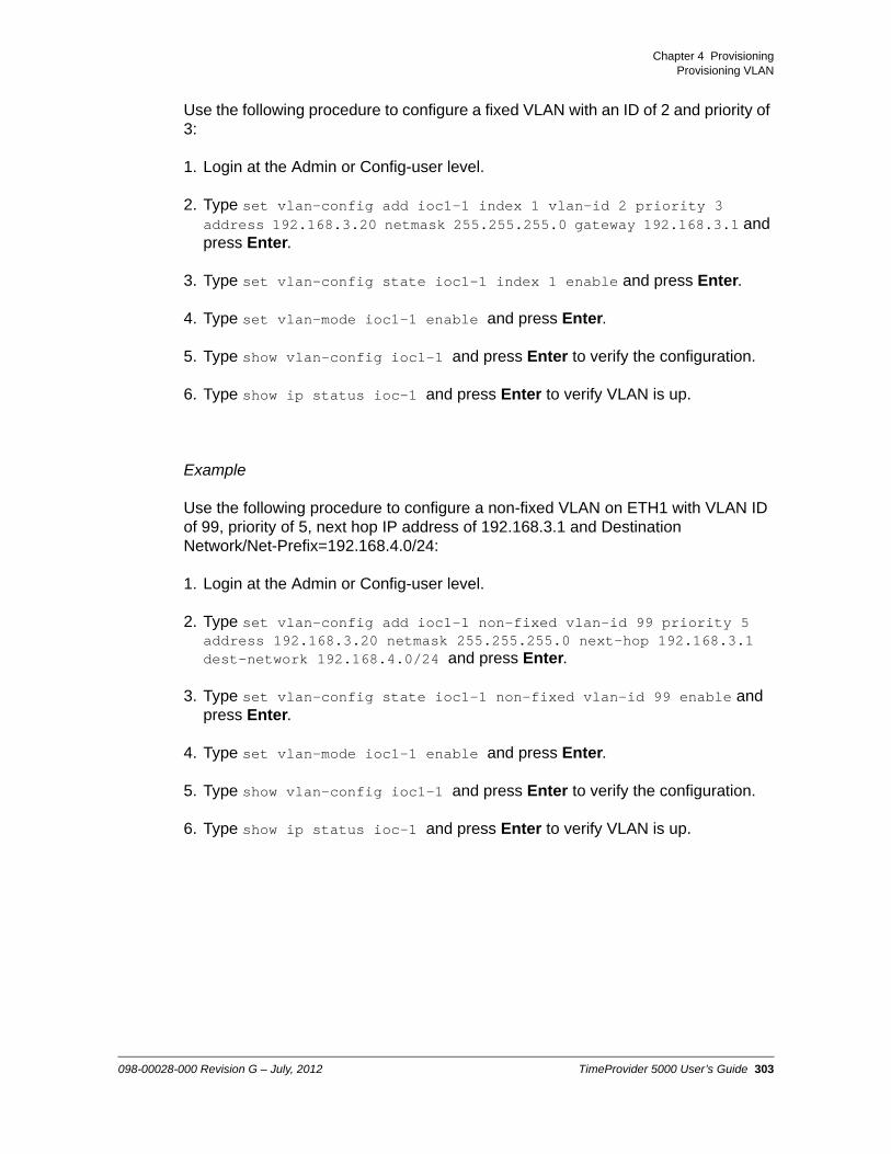
Chapter 4 ProvisioningProvisioning VLAN
Use the following procedure to configure a fixed VLAN with an ID of 2 and priority of 3:
1. Login at the Admin or Config-user level.
2. Type set vlan-config add ioc1-1 index 1 vlan-id 2 priority 3 address 192.168.3.20 netmask 255.255.255.0 gateway 192.168.3.1 and press Enter.
3. Type set vlan-config state ioc1-1 index 1 enable and press Enter.
4. Type set vlan-mode ioc1-1 enable and press Enter.
5. Type show vlan-config ioc1-1 and press Enter to verify the configuration.
6. Type show ip status ioc-1 and press Enter to verify VLAN is up.
Example
Use the following procedure to configure a non-fixed VLAN on ETH1 with VLAN ID of 99, priority of 5, next hop IP address of 192.168.3.1 and Destination Network/Net-Prefix=192.168.4.0/24:
1. Login at the Admin or Config-user level.
2. Type set vlan-config add ioc1-1 non-fixed vlan-id 99 priority 5 address 192.168.3.20 netmask 255.255.255.0 next-hop 192.168.3.1 dest-network 192.168.4.0/24 and press Enter.
3. Type set vlan-config state ioc1-1 non-fixed vlan-id 99 enable and press Enter.
4. Type set vlan-mode ioc1-1 enable and press Enter.
5. Type show vlan-config ioc1-1 and press Enter to verify the configuration.
6. Type show ip status ioc-1 and press Enter to verify VLAN is up.
098-00028-000 Revision G – July, 2012 TimeProvider 5000 User’s Guide 303

Chapter 4 ProvisioningProvisioning PTP
Provisioning PTP
By default, the TP5000 is provisioned as a PTP grandmaster enabled for PTP unicast dynamic negotiation, except for versions that are purchased as dedicated NTP servers. The TP5000 also supports up to 10 unicast static clients per port. The “set ptp” command is used to provision PTP parameters common to Default (multicast), Hybrid (multicast-hybrid), Telecom-2008 (unicast), and ITU-G.8265.1 configurations. See Figure 4-10, Figure 4-11 and Figure 4-12 for the hierarchy of the “set ptp” commands. SeeTable 4-11 for descriptions of the Common parameters and Table B-32 for defaults and ranges. including those commands for setting the ptp profile, management addressing mode and two-step clock mode.
Packet Service Modes
Each Ethernet port on the TP5000 IOC module can be configured as either a PTP grandmaster or as an NTP server, with PTP grandmaster as the default. The exception is for versions that are purchased as dedicated NTP servers. See Figure 4-9.
Figure 4-9. Set Packet-Service Command Hierarchy
Use the following procedure to configure Port 1 of IOC1 as a PTP grandmaster:
1. Login at the Admin.
2. Type set packet-service ioc1-1 ptp-gm and press Enter.
Note: The set packet-service command also allows the user to configure the TP5000 as a PTP probe or NTP probe. A separate option license is required to enable the TP5000 to support either type of probe functionality.
304 TimeProvider 5000 User’s Guide 098-00028-000 Revision G – July, 2012

Chapter 4 ProvisioningProvisioning PTP
PTP Profiles
The TP5000 Grandmaster can be configured to run with one of four PTP profiles, as described in Table 4-4. Each PTP port can run only one of these profiles at one time. However, if the Ethernet ports are configured for independent operation, each port can operate with a different profile. For example, ETH1 can run the Telecom-2008 profile while ETH2 is configured to run the ITU-G.8265-1 profile.
The TP5000 requires a v1.2 license key to unlock the Default (multicast) and Hybrid (multicast-hybrid) profiles. Use the show license command to display the current license...
Table 4-5 shows the output state of the TP5000 main shelf relative to the clock state and clockClass when using the Default (multicast) profile.
SSM Mapping to PTP Clock ClassThe Default, Hybrid, and Telecom-2008 PTP profiles (Unicast, Multicast and Multicast-hybrid address mode) for the TP5000 were implemented before the ITU approved the PTP telecom profile in 2010.
Table 4-4. PTP Profiles for the TP 5000
PTP Profile Mapping to Address Mode (addr-mode in prev release)
Description
Default Multicast Default profile in IEEE1588-2008 Annex J, multicast over UDP/IP. See Table 4-6
Hybrid Multicast-hybrid PTP transport over UDP/IP, mix of unicast /multicast packets. See Table 4-8Proprietary implementation.
Telecom-2008 Unicast Generic unicast profile for telecom before ITU-T G.8265-1. See Table 4-7Proprietary implementation.
ITU G.8265-1 n/a Telecom profile for frequency sync. See Table 4-5for details about TP 5000 compliance to this profile.See ITU-T G.8265.1 for details.
Note: The Ethernet expansion shelf supports the ethernet-default profile. This is the profile defined in IEEE1588-2008 Annex F, multicast over Ethernet.
098-00028-000 Revision G – July, 2012 TimeProvider 5000 User’s Guide 305

Chapter 4 ProvisioningProvisioning PTP
To be fully compliant to the ITU telecom profile, a PTP protocol must support the mapping between SSM and PTP clockClass as defined in G. 8265.1. The SSM QL value, defined in ITU-T G.781, is transferred through the Clock Class attribute carried in PTP Announce messages. This mapping is explicitly defined for frequency synchronization, but Symmetricom’s implementation assumes it is applicable to time synchronization. See Table 4-9 and Table 4-10 for Symmetricom’s implementation of the G.8265.1 SSM-clockClass mapping table.
Table 4-5 shows the compliance of the ITU-8265.1 PTP profile for the TP5000 to the ITU 8265.1 standard.
Table 4-6 shows the compliance of the Default (multicast) PTP profile for the TP5000 to IEEE 1588-2008 Annex J.
Table 4-7 and Table 4-8 show the attributes for the proprietary Telecom-2008 (unicast) and Hybrid (multicast-hybrid) PTP profiles, respectively.
Table 4-5. ITU-T G.8265-1 Profile Compliance
AttributeDefault for
ITU-T G.8265-1Default for
TP 5000Range for
ITU-T G.8265-1Range forTP 5000
clockClass Not defined Not defined 80 to 110 80 to 110
Domain 4 4 4 to 23 0 to 255
Table 4-6. Default Profile (Multicast) Compliance - IEEE1588-2008 Annex J
AttributeDefault for
Annex JDefault for
TP 5000Range for Annex J
Range forTP 5000
clockClass n/a 6, 7, 13, 14, 52, 58, 248
Announce Interval 1 1 0 to +4 -4 to +4
Sync Interval 0 -1 -1 to +1 -7 to +7
Domain 0 0 Not defined 0 to 255
Table 4-7. Telecom-2008 (Unicast) Proprietary Profile
AttributeDefault for TP
5000Range for TP 5000
clockClass Not defined 6, 7, 13, 14, 2, 58, 248
Domain 4 0 to 255
306 TimeProvider 5000 User’s Guide 098-00028-000 Revision G – July, 2012

Chapter 4 ProvisioningProvisioning PTP
Table 4-8. Hybrid (Multicast-Hybrid) Proprietary Profile
Attribute Default for TP 5000 Range for TP 5000
clockClass Not defined 6, 7, 13, 14, 52, 58, 248
Announce Interval -3 -4 to +4
Sync Interval -7 -7 to +7
Domain 4 0 to 255
Table 4-9. Option 1 - SSM Mapping to QL and clockClass per G.781 and G.8265-1
Option 1 SSM (hex) Clock QL PTP clockClass PQL
04FF QL-PRC 84 1
08FF STU 82 2
0CFF QL-SSU-A 90 3
0CFF Type I 90 4
78FF QL-SSU-B 96 6
10FF QL-SEC/EEC1 104 7
30FF QL-DNU 110 9
Others (or absent) Invalid n/a 15
Table 4-10. Option 2 - SSM Mapping to QL and clockClass per G.781 and G.8265-1
Option 2 SSM (hex) Clock QL PTP clockClass PQL
04FF QL-PRS 80 1
08FF QL-STU 82 2
0CFF QL-ST2 86 3
0CFF Type I 86 4
78FF QL-TNC 90 5
7CFF QL-ST3E 100 6
10FF QL-ST3E/EEC2 102 7
098-00028-000 Revision G – July, 2012 TimeProvider 5000 User’s Guide 307
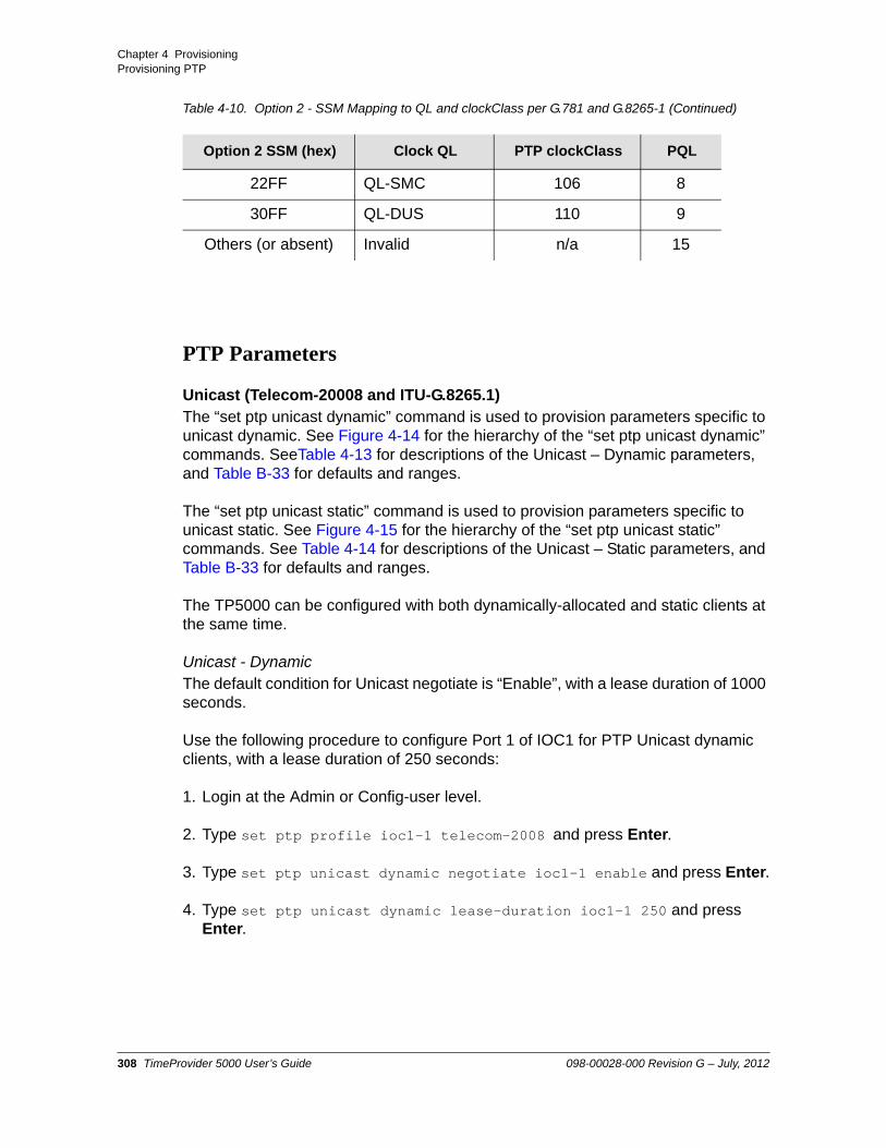
Chapter 4 ProvisioningProvisioning PTP
PTP Parameters
Unicast (Telecom-20008 and ITU-G.8265.1)The “set ptp unicast dynamic” command is used to provision parameters specific to unicast dynamic. See Figure 4-14 for the hierarchy of the “set ptp unicast dynamic” commands. SeeTable 4-13 for descriptions of the Unicast – Dynamic parameters, and Table B-33 for defaults and ranges.
The “set ptp unicast static” command is used to provision parameters specific to unicast static. See Figure 4-15 for the hierarchy of the “set ptp unicast static” commands. See Table 4-14 for descriptions of the Unicast – Static parameters, and Table B-33 for defaults and ranges.
The TP5000 can be configured with both dynamically-allocated and static clients at the same time.
Unicast - DynamicThe default condition for Unicast negotiate is “Enable”, with a lease duration of 1000 seconds.
Use the following procedure to configure Port 1 of IOC1 for PTP Unicast dynamic clients, with a lease duration of 250 seconds:
1. Login at the Admin or Config-user level.
2. Type set ptp profile ioc1-1 telecom-2008 and press Enter.
3. Type set ptp unicast dynamic negotiate ioc1-1 enable and press Enter.
4. Type set ptp unicast dynamic lease-duration ioc1-1 250 and press Enter.
22FF QL-SMC 106 8
30FF QL-DUS 110 9
Others (or absent) Invalid n/a 15
Table 4-10. Option 2 - SSM Mapping to QL and clockClass per G.781 and G.8265-1 (Continued)
Option 2 SSM (hex) Clock QL PTP clockClass PQL
308 TimeProvider 5000 User’s Guide 098-00028-000 Revision G – July, 2012

Chapter 4 ProvisioningProvisioning PTP
Unicast - StaticThe default condition for Unicast Static is “Disable”. See Table B-32 for default values for other Unicast Static parameters.
Use the following procedure to configure IOC1, Port 1 for 2 Unicast Static clients:
Client 1: 10.11.11.101, VLAN ID=10, index=1, Clock ID: 0A:11:22:33:44:55:66:77,Synchronization interval rate = 16 per second (sync-int value = -4) , Announce interval rate = 1 per second (announce-int value = 0),Delay interval rate = 8 per second (delay-int value = -3)
Client 2: 10.21.21.101, VLAN ID=20, index=2, Clock ID: 0A:22:33:44:55:66:77:88Synchronization interval rate = 32 per second (sync-int value = -5) , Announce interval rate = 1 per second (announce-int value = 0),Delay interval rate = 16 per second (delay-int value = -4)
1. Login at the Admin or Config-user level.
2. Type set ptp profile ioc1-1 telecom-2008 and press Enter.
3. Type set ptp unicast static address ioc1-1 index 1 10.11.11.101 and press Enter.
4. Type set ptp unicast static vlanid ioc1-1 index 1 add 10 and press Enter.
5. Type set ptp unicast static clockid ioc1-1 index 1 0A:11:22:33:44:55:66:77 and press Enter.
6. Type set ptp unicast static sync-int ioc1-1 index 1 -4 and press Enter.
7. Type set ptp unicast static announce-int ioc1-1 index 1 0 and press Enter.
8. Type set ptp unicast static delay-int ioc1-1 index 1 -3 and press Enter.
9. Type set ptp unicast static state ioc1-1 index 1 enable and press Enter.
10.Type set ptp unicast static address ioc1-1 add index 2 10.21.21.101 and press Enter.
Note: Each VLAN must be configured on a separate subnet. See Provisioning VLAN and the set vlan command for details.
098-00028-000 Revision G – July, 2012 TimeProvider 5000 User’s Guide 309

Chapter 4 ProvisioningProvisioning PTP
11.Type set ptp unicast static vlanid ioc1-1 index 2 vlanid 20 and press Enter.
12.Type set ptp unicast static clockid ioc1-1 add index 2 0A:22:33:44:55:66:77:88 and press Enter.
13.Type set ptp unicast static sync-int ioc1-1 index 2 -5 and press Enter.
14.Type set ptp unicast static announce-int ioc1-1 index 2 0 and press Enter.
15.Type set ptp unicast static delay-int ioc1-1 index 2 -4 and press Enter.
16.Type set ptp unicast static state ioc1-1 index 2 enable and press Enter.
Multicast (Default)The TP5000 grandmaster operates per the multicast communication model, which specifies that each PTP message sent from the grandmaster is capable of being received and processed by all PTP ports on the same PTP communication path. The “set ptp multicast” command is used to provision parameters specific to multicast addressing mode (hybrid or Default profile). See Figure 4-13 for the hierarchy of the “set ptp multicast” commands and Table 4-12 for defaults and ranges.
In multicast mode, there are no client leases or client limits. All delay requests will be responded to. There is no limit applied to the number of delay responses supported, other than the maximum capacity of the Ethernet link and the packet engine.
Note: If the client is not reachable, the “set ptp unicast static state” command will fail.
Note: The TP5000 requires a 1.2 feature license key to unlock the multicast addressing mode feature. Use the show license current command to display the current license.
310 TimeProvider 5000 User’s Guide 098-00028-000 Revision G – July, 2012

Chapter 4 ProvisioningProvisioning PTP
In multicast mode, the TP5000 creates a client list by examining the received PTP delay request messages. In order for a client to be reliably added to the client list and not removed, the TP5000 needs to receive several hundred delay request messages during the client timeout period. If delay requests are sent at a slow rate, then the client-timeout value must be increased. Since one-way PTP operation does not use delay request and delay response messages, the client list will not be populated in this mode.
Only one VLAN will be supported in multicast mode.
Use the following procedure to configure Port 1 of IOC1 for multicast addressing mode:
1. Login at the Admin or Config-user level.
2. Type set ptp profile ioc1-1 default and press Enter.
Multicast-Hybrid (Hybrid)The Hybrid profile (multicast-hybrid) sends sync and announce messages using multicast, but sends delay request and delay response messages using unicast. This minimizes the amount of network traffic.
The TP5000 will support unicast negotiation for the delay requests. If the client limit is reached, then the unicast negotiation request will be denied.
The TP5000 will also support lease-less clients. These clients will operate in multicast-hybrid mode, but will not request a lease via unicast negotiation. To support this, the TP5000 will respond to all delay requests, regardless of whether there is a lease for that client. The “set ptp multicast” command is used to provision parameters specific to the Hybrid PTP profile. See Figure 4-13 for the hierarchy of the “set ptp multicast” commands and Table 4-12 for defaults and ranges.
The TP5000 will automatically learn lease-less clients. When the combined total of clients (unicast-negotiated and lease-less clients) reaches 500, the TP5000 will not grant new leases to unicast negotiation requests but it will respond to all new lease-less clients.
Only one VLAN will be supported in multicast-hybrid mode. See Provisioning VLAN, on page 300 for details.
Note: The TP5000 requires a current license key to unlock the Hybrid (multicast-hybrid) PTP profile feature. Use the show license command to display the current license.
098-00028-000 Revision G – July, 2012 TimeProvider 5000 User’s Guide 311

Chapter 4 ProvisioningProvisioning PTP
Use the following procedure to configure Port 2 of IOC1 for Hybrid (multicast-hybrid) PTP profile:
1. Login at the Admin or Config-user level.
2. Type set ptp profile ioc1-2 hybrid and press Enter.
Management Addressing Mode
The TP5000 allows user to configure whether management messages are sent to clients via Unicast or Multicast addresses. If the parameter is set to multicast, then all ptp management messages directed to clients will be sent using the PTP multicast IP address. The management addressing mode is independent of the PTP synchronization addressing mode.
Use the “set ptp mgmt-addr-mode IOC1-y { multicast | unicast}” command to configure the TP5000 for multicast or unicast management address mode. The default management address mode is unicast.
Only one VLAN is supported in multicast mode. See Provisioning VLAN, on page 300 for details.
Use the following procedure to configure Port 1 of IOC 1 for unicast management address mode and Port 2 of IOC1 for multicast management addressing mode:
1. Login at the Admin or Config-user level.
2. Type set ptp mgmt-addr-mode ioc1-1 unicast and press Enter.
3. Type set ptp mgmt-addr-mode ioc1-2 multicast and press Enter.
Note: The TP5000 requires a current license key to unlock the multicast management addressing mode feature. Use the show license command to display the current license.
312 TimeProvider 5000 User’s Guide 098-00028-000 Revision G – July, 2012

Chapter 4 ProvisioningProvisioning PTP
Two-Step Clock Mode
A two-step clock includes a follow-up packet after the Sync packet from the grandmaster, as shown in Figure 4-16. Use the “set ptp two-step IOC1-y enable” command to enable the grandmaster for two-step clock mode on the specified port.
A one-step clock does not include a follow-up packet after the Sync packet from the grandmaster, as shown in Figure 4-17. If two-step clock mode is disabled, the grandmaster uses one-step clock mode.
Two-step clock mode is disabled by default.
Use the following procedure to configure Port 1 of IOC1 for two-step clock mode:
1. Login at the Admin or Config-user level.
2. Type set ptp two-step ioc1-1 enable and press Enter.
Figure 4-10. Set PTP Command Hierarchy Common
Note: The TP5000 requires a current license key to unlock the two-step clock mode feature. Use the show license command to display the current license.
098-00028-000 Revision G – July, 2012 TimeProvider 5000 User’s Guide 313

Chapter 4 ProvisioningProvisioning PTP
Figure 4-11. Set PTP Command Hierarchy Common
Figure 4-12. Set PTP Command Hierarchy Common (cont’d)
Figure 4-13. Set PTP Multicast Hierarchy
314 TimeProvider 5000 User’s Guide 098-00028-000 Revision G – July, 2012

Chapter 4 ProvisioningProvisioning PTP
Figure 4-14. Set PTP Command Hierarchy Unicast Dynamic
Figure 4-15. Set PTP Command Hierarchy Unicast Static
Table 4-11. PTP Common Parameter Descriptions
Parameter Description
profile Use to control whether Grandmaster operates with Default (Multicast), Hybrid (Multicast-hybrid), Telecom-2008 (Unicast), or ITU-G.8265-1 profile for the specified port.
mgmt-addr-mode Use to control whether PTP management messages should use unicast or multicast. This setting is independent of the addr-mode. For example, management can be set for multicast while PTP synchronization is using unicast. For multicast management, the client must be in the client list.
098-00028-000 Revision G – July, 2012 TimeProvider 5000 User’s Guide 315

Chapter 4 ProvisioningProvisioning PTP
two-step Use to enable the grandmaster for two-step clock mode on the specified port. If two-step clock mode is disabled, the grandmaster uses one-step clock mode.
timescale Use to select the timescale for the selected port. Use the PTP timescale if the Grandmaster has a GPS connection for the clock. Use the ARB timescale if the Grandmaster has an E1 or T1 signal for the clock. Use the AUTO setting (recommended) to have the Grandmaster automatically set the timescale based on the selected clock source, GPS, T1 or E1.
state Use to enable or disable PTP functionality for the specified port.
ttl Use to set the IP header Time-to-Live value This field is used to limit how many hops a packet will be transmitted in a network. This is especially useful with multicast.
alternate-master Use to set the alternate master flag. If the alternate master flag is set, the TP5000 will not run the BMC algorithm and will always be master.
max-client Sets the maximum number of PTP clients the user chooses to allow for the specified port. The TP5000 has a capacity for up to 500 clients per port.
announce-limit Use to limit the minimum interval between announcements (maximum rate) from the specified TP5000. This is a way to restrict how network resources will be utilized. The interval is 2z seconds, where z= <announce-limit-value>.
sync-limit Use to limit the minimum interval between synchronization messages (maximum rate) from the specified TP5000 port. This is a way to restrict how network resources will be utilized.The interval is 2z seconds, where z= <sync-limit-value>.
delay-limit Use to limit the minimum interval between between delay requests for the specified TP5000 port. This is a way to restrict how network resources will be utilized.The interval is 2z seconds, where z= <delay-limit-value>.
Table 4-11. PTP Common Parameter Descriptions (Continued)
Parameter Description
316 TimeProvider 5000 User’s Guide 098-00028-000 Revision G – July, 2012

Chapter 4 ProvisioningProvisioning PTP
priority-1 Sets the advertised Priority 1 value for the Grandmaster for the specified port. PTP clients use the Best Master Clock (BMC) algorithm to determine which Grandmaster provides the best signal by first comparing Priority 1 values, then dynamic elements from the Grandmasters (such as clock class, accuracy and variance), and then Priority 2 values.
priority-2 Sets the advertised Priority 2 value for the Grandmaster for the specified port. Clients use the Best Master Clock (BMC) algorithm to determine which Grandmaster provides the best signal by first comparing Priority 1 values, then dynamic elements from the Grandmasters (such as clock class, accuracy and variance), and then Priority 2 values.
domain Sets the domain value for the Grandmaster clock. IEEE-1588-2008 defines a domain as a logical grouping of clocks that synchronize to each other using the protocol, but that are not necessarily synchronized to clocks in another domain.
dscp The Differentiated Services Code Point is an 6-bit field in the 8-bit Differentiated Services (DS) field of the IP packet header to specify what classes of traffic will be provided, what guarantees are needed for each class, and how much data will be sent for each class. When used with the TP5000, it provides a way to prioritize packets for PTP traffic.
dscp-state This is to enable or disable the use of DSCP.
dither This is an advanced feature in which an intentionally applied form of noise is used to randomize quantization error, and thus to break up any undesirable synchronizing effects with the network. With dither enabled, the TP5000 varies the T1 timestamp by a pseudo-random sequence with peak variations of no more than +/- 800 sec.
clockid This is the PTP master Clock ID for the specified PTP port. The Clock ID for a PTP port on Symmetricom’s TP5000 is typically based on the MAC value for that port, with FF:FE inserted in the middle of the MAC address. This command allows the user to manually set the Clock ID to a desired value. The Clock ID is in the form xx:xx:xx:xx:xx:xx:xx:xx
Table 4-11. PTP Common Parameter Descriptions (Continued)
Parameter Description
098-00028-000 Revision G – July, 2012 TimeProvider 5000 User’s Guide 317
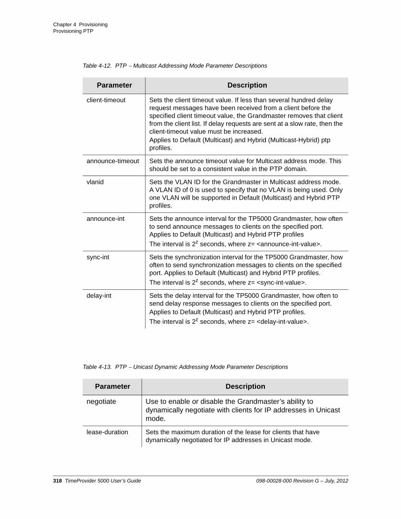
Chapter 4 ProvisioningProvisioning PTP
Table 4-12. PTP Multicast Addressing Mode Parameter Descriptions
Parameter Description
client-timeout Sets the client timeout value. If less than several hundred delay request messages have been received from a client before the specified client timeout value, the Grandmaster removes that client from the client list. If delay requests are sent at a slow rate, then the client-timeout value must be increased.Applies to Default (Multicast) and Hybrid (Multicast-Hybrid) ptp profiles.
announce-timeout Sets the announce timeout value for Multicast address mode. This should be set to a consistent value in the PTP domain.
vlanid Sets the VLAN ID for the Grandmaster in Multicast address mode. A VLAN ID of 0 is used to specify that no VLAN is being used. Only one VLAN will be supported in Default (Multicast) and Hybrid PTP profiles.
announce-int Sets the announce interval for the TP5000 Grandmaster, how often to send announce messages to clients on the specified port. Applies to Default (Multicast) and Hybrid PTP profiles
The interval is 2z seconds, where z= <announce-int-value>.
sync-int Sets the synchronization interval for the TP5000 Grandmaster, how often to send synchronization messages to clients on the specified port. Applies to Default (Multicast) and Hybrid PTP profiles.
The interval is 2z seconds, where z= <sync-int-value>.
delay-int Sets the delay interval for the TP5000 Grandmaster, how often to send delay response messages to clients on the specified port. Applies to Default (Multicast) and Hybrid PTP profiles.
The interval is 2z seconds, where z= <delay-int-value>.
Table 4-13. PTP Unicast Dynamic Addressing Mode Parameter Descriptions
Parameter Description
negotiate Use to enable or disable the Grandmaster’s ability to dynamically negotiate with clients for IP addresses in Unicast mode.
lease-duration Sets the maximum duration of the lease for clients that have dynamically negotiated for IP addresses in Unicast mode.
318 TimeProvider 5000 User’s Guide 098-00028-000 Revision G – July, 2012

Chapter 4 ProvisioningProvisioning PTP
Figure 4-16. Two-Step Clock
Table 4-14. PTP Unicast Static Addressing Mode Parameter Descriptions
Parameter Description
state Use to enable or disable Unicast - Static mode on the TP5000 on the specified port.
address Sets the static IP address for a client for the specified port.
clock-id Use to enter the clock ID for the specified client.
vlanid Use to enter the VLAN ID to be used for the specified client on the specified port. The VLAN must configured and enabled in order to use this. (See Provisioning VLAN, on page 300)
sync-int Sets the synchronization interval for the TP5000 Grandmaster, how often to send synchronization messages (T1) to clients on the specified port. The interval is 2z seconds, where z= <sync-int-value>.
announce-int Sets the announce interval for the TP5000 Grandmaster, how often to send announce messages to clients on specified port.The interval is 2z seconds, where z= <announce-int-value>.
delay-int Sets the delay interval for the TP5000 Grandmaster, how often to expect to receive delay request messages (T3 - T4) from clients on the specified port. The interval is 2z seconds, where z= <delay-limit-value>.
098-00028-000 Revision G – July, 2012 TimeProvider 5000 User’s Guide 319

Chapter 4 ProvisioningProvisioning PTP
Figure 4-17. One-Step Clock
320 TimeProvider 5000 User’s Guide 098-00028-000 Revision G – July, 2012

Chapter 4 ProvisioningProvisioning NTP
Provisioning NTP
Each Ethernet port on the TP5000 IOC module can be configured as either a PTP grandmaster or as an NTP server, with PTP grandmaster as the default mode. The exception is for versions that are purchased as dedicated NTP servers.
Use the set packet-service command to configure the IOC port with a packet-service mode of NTP server. See Figure 4-9 for the set packet-service command hierarchy.
Use the set ntp command to enable NTP on an IOC port and to configure the DSCP and TTL parameters. See Figure 4-18 for the set ntp command hierarchy.
Use the command set packet-service ioc1-x ptp-gm to return an IOC port to a packet service mode of PTP grandmaster.
Figure 4-18. Set NTP Command Hierarchy
Note: The NTP Server feature can either be ordered in a new system, or added to a previously ordered system as a field upgrade. Field upgrades require a license activation key. Contact your Symmetricom representative for more information.
Note: The IP address for the IOC port is configured with the set ip command whether the port is configured as an NTP server or PTP grandmaster.
098-00028-000 Revision G – July, 2012 TimeProvider 5000 User’s Guide 321

Chapter 4 ProvisioningProvisioning NTP
Provisioning an IOC Port as NTP Server
Use the following procedure to configure and enable Port 2 of IOC1 as an NTP server, with DSCP enabled, a DSCP value of 64 and TTL value of 25:
1. Login at the Admin or Config-user level.
2. Type show ntp config ioc-2 to check current NTP status.
3. Type set packet-service ioc1-2 ntp-server and press Enter.
4. Type set ntp dscp-state ioc1-2 enable and press Enter.
5. Type set ntp dscp ioc1-2 64 and press Enter.
6. Type set ntp ttl ioc1-2 25 and press Enter.
7. Type set ntp state ioc1-2 enable and press Enter.
8. Type show ntp config ioc-2 to verify the changes.
322 TimeProvider 5000 User’s Guide 098-00028-000 Revision G – July, 2012

Chapter 4 ProvisioningProvisioning the Input Reference
Provisioning the Input Reference
When operating in normal (locked) mode, the TimeProvider 5000 uses an external reference (such as GPS) to acquire the system’s frequency and/or TOD alignment. Table 4-15 shows the configurable parameters for reference selection.
Setting Reference Mode
The TP 5000 can be in either Time mode or Frequency mode for reference selection. GPS, GNSS and 1PPS+TOD references inputs are time references. The E1 and T1 reference inputs are frequency references.
Time ModeIn Time mode with a time reference, the system will track the phase of the input and the system time will be set from the time of the input reference. With a frequency input reference, the system will only track the frequency of the reference.
Table 4-15. Configurable Parameters for Reference Selection
Parameter Value Range Description/Notes
Reference Mode Time
Frequency
Selecting "Time" means some outputs need to track reference time and phase.
Selecting "Frequency" means it is not necessary for the outputs to track reference time and phase.
Reference Criteria Priority
SSMSee Setting Reference Criteria, on page 324.
Network Option Option I
Option II
SSM Option 1 is for E1 sync networks,
SSM Option 2 is for T1 sync networks.
As defined in ITU G.781 and G.8265.1
See Synchronization Status Message (SSM), on page 332 for details about Network SSM Options
Priority (per port)
1 to 16 See Setting Input Priority Values, on page 325
QL (per port)
1 to 9 GNSS and PPS-TOD ports are hardcoded with QL value that correspond to PRC/PRS. See Table 4-16
Reference Port State (per port)
Enable
Disable
098-00028-000 Revision G – July, 2012 TimeProvider 5000 User’s Guide 323

Chapter 4 ProvisioningProvisioning the Input Reference
Frequency ModeIn Frequency mode, the system will track the frequency of the input reference. Any phase or time information from a time reference will not be used in Frequency mode.
Figure 4-19. Set Ref Command Hierarchy
Example
1. Login at the Admin or Config-user level (see Logging In, on page 275).
2. Type set ref mode time and press Enter.
Setting Reference Criteria
The TP 5000 can use either the Priority settings or the SSM settings for each qualified input port to determine which input port to use as the reference.
Example
1. Login at the Admin or Config-user level (see Logging In, on page 275).
2. Type set ref criteria priority and press Enter.
Note: The command “set ref mode time” has the same meaning as “set tod-source GPS” and “set ref mode frequency” has the same meaning as “set tod-source sys”. The set tod-source command is deprecated.
Note: The reference criterion MANUAL is no longer supported. Only PRIORITY and SSM are supported for reference selection.
Manual selection of a reference input can be done by disabling all reference input ports except the desired one.
The “set ref override” command is no longer supported.
324 TimeProvider 5000 User’s Guide 098-00028-000 Revision G – July, 2012

Chapter 4 ProvisioningProvisioning the Input Reference
Example
1. Type set ref criteria ssm and press Enter.
Setting Input Priority Values
The TP 5000 uses the Priority settings for each qualified input port to determine which input port to use as the reference. Priority values can be from 1 to 16, where 1 is the highest priority level. If two input ports are set to the same priority value and both are qualified, the predefined preference is used (see Table 4-16). Predefined preference has the same value as the default priority value, but cannot be changed. Reference selection among inputs with the same priority is non-revertive.
In Time mode, time references are selected first, even if a frequency reference has a higher priority setting than the time references. In Time mode, there must be at least one qualified time reference for the system to get out of the warm-up state and into normal track state. If all time references are disabled or disqualified after the system gets to a normal track state, a frequency reference will be used for time holdover.
In Frequency mode, all reference inputs (time reference and frequency reference) are used. The reference selection is based only on priority.
Example
1. Login at the Admin or Config-user level (see Logging In, on page 275).
2. Type set ref criteria priority and press Enter.
3. Type set gps priority 1 and press Enter.
4. Type set gnss priority 2 and press Enter.
5. Type set pps-tod priority port1 3 and press Enter.
6. Type set pps-tod priority port2 4 and press Enter.
7. Type set input priority port1 5 and press Enter.
Note: With the 090-50331-04 version of the IMC card, the GNSS port can receive Beidou and GPS satellite RF input. The GNSS track-mode parameter is used to specify the tracking priority for signals to the GNSS port. See Figure 4-21 for details or see set gnss command.
098-00028-000 Revision G – July, 2012 TimeProvider 5000 User’s Guide 325

Chapter 4 ProvisioningProvisioning the Input Reference
8. Type set input priority port2 6 and press Enter.
9. Type show ref and press Enter to verify that Priority values have been set to the desired values.
Setting GPS Port as Reference
When the GPS reference is enabled, you can set the satellite position parameters either automatically or manually. The GPS reference input is enabled by default. In manual mode, you must specify the latitude, longitude, and height. You can also specify the elevation mask which filters the satellites used by the system.
Table 4-16. Reference Modes and Priorities
Input Port Card Ref. TypeReference
CriteriaPriority (Default)
Predefined Preference
PQL(Default)
GNSS IMC Time Priority 1 1 1
GPS IMC Time Priority 2 2 1
1PPS+TOD Port 1 I/O Time Priority 3 3 1
1PPS+TOD Port 2 I/O Time Priority 4 4 1
E1 / T1 Port 1 I/O Frequency Priority 7 7 3
E1 / T1 Port 2 I/O Frequency Priority 8 8 3
Note: Manual mode should not be used unless antenna location has been accurately surveyed. See the set gps command description for for details about setting GPS position parameters manually.
326 TimeProvider 5000 User’s Guide 098-00028-000 Revision G – July, 2012

Chapter 4 ProvisioningProvisioning the Input Reference
Figure 4-20. Set GPS Command Hierarchy
Example
To provision the TimeProvider 5000 for a GPS reference in auto mode, perform the following steps:
1. Login at the Admin or Config-user level (see Logging In, on page 275).
2. Type set ref mode time and press Enter.
3. Type set gps mode auto and press Enter.
4. Type set gps state enable and press Enter.
5. Type show ref and press Enter to verify that the reference mode has been set to Time.
098-00028-000 Revision G – July, 2012 TimeProvider 5000 User’s Guide 327

Chapter 4 ProvisioningProvisioning the Input Reference
Setting GNSS Port as Reference
To provision the TimeProvider 5000 for GNSS, use the set ref mode time command to select a Time mode. Use the set gnss command to provision the GNSS port state and GNSS parameters.
Track-ModeThe Priority setting for GNSS is for the GNSS port itself. However, the GNSS port for the 090-50331-04 can receive Beidou and GPS satellite RF inputs. (Future implementations of the IMC card may support RF inputs from other satellites.) The GNSS track-mode parameter is used to specify the tracking priority for the GNSS port.
GPS: Only checks for qualified GPS on this port
Beidou: Only checks for qualified Beidou on this port
Priority-beidou: Checks for qualified Beidou signal before checking for GPS
Priority-gps : Checks for qualified GPS signal before checking for Beidou
Figure 4-21. Set GNSS Command Hierarchy
Example
Note: Manual mode should not be used unless antenna location has been accurately surveyed. See the set gnss command description for for details about setting GNSS position parameters manually.
328 TimeProvider 5000 User’s Guide 098-00028-000 Revision G – July, 2012

Chapter 4 ProvisioningProvisioning the Input Reference
To provision the TimeProvider 5000 for a GNSS reference in auto mode, with a track-mode of Priority-beidou, perform the following steps:
1. Login at the Admin or Config-user level (see Logging In, on page 275).
2. Type set ref mode time and press Enter.
3. Type set gnss mode auto and press Enter.
4. Type set gnss track-mode priority-beidou and press Enter.
5. Type set gnss state enable and press Enter.
6. Type show ref and press Enter to verify that the reference mode has been set to Time.
Setting a 1PPS+TOD Input as Reference
Ports 1 and 2 on the 090-50315-01 version of the I/O module are 1PPS+TOD inputs. Use the following procedure to set these ports as reference inputs and to enable the inputs.
Example
To provision the TimeProvider 5000 for a 1PPS+TOD input reference, perform the following steps:
1. Login at the Admin or Config-user level.
2. Type set ref mode time and press Enter
3. Type set pps-tod state port1 enable and press Enter.
4. Type set pps-tod state port2 enable and press Enter.
5. Type show ref and press Enter to verify that the reference mode has been set to Time.
Note: Disabling the input port will clear all alarms and events related to this port.
Note: Command “set ref mode time” has the same meaning as “set tod-source GPS” and “set ref mode frequency” has the same meaning as “set tod-source sys”. The set tod-source command has been deprecated.
098-00028-000 Revision G – July, 2012 TimeProvider 5000 User’s Guide 329

Chapter 4 ProvisioningProvisioning the Input Reference
Setting an E1/T1 Input as Reference
An E1 or T1 input can be configured as a frequency reference. For details about configuring the E1 or T1 input parameters, see Provisioning the Programmable E1/T1 Inputs, on page 331.
Example
To provision I/O ports 1 and 2 as inputs and use either as the reference, perform the following steps:
1. Login at the Admin or Config-user level (see Logging In, on page 275).
2. Type set ref mode frequency and press Enter.
3. Type set ref criteria priority and press Enter.
4. Type set io port1 input and press Enter.
5. Type set io port2 input and press Enter.
6. Type set input state port1 enable and press Enter.
7. Type set input state port2 enable and press Enter.
Note: Command “set ref mode time” has the same meaning as “set tod-source GPS” and the command “set ref mode frequency” has the same meaning as “set tod-source sys”. The set tod-source command has been deprecated.
Note: The reference criterion MANUAL is no longer supported. Only PRIORITY and SSM are supported for reference selection.
Manual selection of a reference input can be done by disabling all reference input ports except the desired one.
The “set ref override” command is no longer supported.
Note: Enabling the input state for a programmable I/O port with the “set input state” command will also set that port as an input port and set the output state for that port to Disable.
330 TimeProvider 5000 User’s Guide 098-00028-000 Revision G – July, 2012

Chapter 4 ProvisioningProvisioning the Programmable E1/T1 Inputs
8. Type show ref and press Enter to verify that the reference mode has been set to Frequency..
Provisioning the Programmable E1/T1 Inputs
Two I/O ports on the I/O module (versions 090-50311-01, 090-50312-01, and 090-50315-01), Port1 and Port 2, are software configurable as E1 inputs. Two RJ-48 I/O ports on the I/O module (p/n 090-50314-01), Port1 and Port 2, are software configurable as T1 inputs. The “set io” command is used to set Ports 1 and 2 as inputs. See Figure 4-22. The “set input” command is used to provision the ports as E1 or T1 inputs. See Figure 4-23.
Figure 4-22. Set IO Command Hierarchy
Figure 4-23. Set Input Command Hierarchy
Note: Disabling the input port will clear all alarms and events related to this port.
098-00028-000 Revision G – July, 2012 TimeProvider 5000 User’s Guide 331

Chapter 4 ProvisioningProvisioning the Programmable E1/T1 Inputs
Synchronization Status Message (SSM)
Synchronization Status Message (SSM) is a means by which elements in a synchronization network can communicate the traceability of their sync quality level. SSM is only supported for the frametypes ESF, CAS with CRC4 and CCS with CRC4. SSM should not be enabled for other input frame types. The messages will be decoded and used for reference input qualification if SSM is enabled for the input port.
If SSM is enabled for an input port and the frametype does not support SSM or is not sending a valid SSM, then the input will be disqualified and the input SSM-value will be set to 15 (invalid). If there is not another qualified reference to switch to, the system will go to holdover. See Table 4-17 for examples.
If input SSM for a port has a worse quality level than the IOC oscillator - Type II for Rb IOC and Type 1 for Quartz IOC -the input port will be disqualified
If SSM is enabled for an input port and the signal does not support SSM or is not sending a valid SSM, then the input will be disqualified. The SSM-value for the input will be set to 15 (invalid). If there is not another qualified reference to switch to, the system will go to holdover.
If any of the following conditions are detected at an input port, that input signal will be disqualified: Loss of signal (LOS), Out-of-framing (OOF), or Alarm indication signal (AIS)
Table 4-17 illustrates some example situations. The Output PQL values shown assume that no other references are available
332 TimeProvider 5000 User’s Guide 098-00028-000 Revision G – July, 2012

Chapter 4 ProvisioningProvisioning the Programmable E1/T1 Inputs
Table 4-17. Input Frametypes: SSM-States and SSM-values
PQL-ValueThe “PQL value” parameter that is used with the “set input” command corresponds to the Priority Quality Level (PQL) values for reference input signal types, as shown in Table 4-18. The PQL is a representation of traceability for the signal presented at the input ports, where a PQL value of 15 represents an invalid SSM. If SSM is disabled for an input port, then the TP5000 will use the user-assigned PQL value for that input port.
SSM Bit
The SSM bit indicates which bit of the framing signal carries the SSM.
Selected Input
SignalSSM State
Current PQL value
Disqualify Signal Based on SSM?
Output PQL value
1544kHz Disable User-value Allow User-value
Enable 15 Disqualify OSC (holdover)
D4 Disable User-value Allow User-value
Enable 15 Disqualify OSC (holdover)
ESF Disable User-value Allow User-value
Enable with valid SSM Input SSM Allow Input SSM
with no SSM 15 Disqualify OSC (holdover)
with unsupported SSM code
15 Disqualify OSC (holdover)
with STU code 2 (STU) Allow 2 (STU)
with DUS code 9 (DUS) Disqualify OSC (holdover)
Note: SSM during bridging will be the last SSM value of input reference while clock was in normal lock state.
Note: The SSM bit is not applicable to T1 signals. The TP5000 will allow the user to set the SSM bit parameter for T1 signals, but it will have no effect.
098-00028-000 Revision G – July, 2012 TimeProvider 5000 User’s Guide 333

Chapter 4 ProvisioningProvisioning the Programmable E1/T1 Inputs
Table 4-18. Priority Quality Levels
CRC State
CRC is a cyclic redundancy checking protocol which is applicable for E1 signals. CRC must be enabled for the input port in order to use SSM with the CAS or CCS framing types for that port.
Provisioning E1 Inputs
Use the following procedures to provision Port 1 or 2 as an E1 input.
Priority Quality Level
(PQL)
DS1 (T1) SSM
E1 SSM Description
1 0x04 0x02 Stratum 1/PRS/PRC
2 0x08 0x00 STU, Stratum Unknown (presumed ST1)
3 0x0C 0x04 Stratum 2/Type II
4 0x0C 0x04 Type I
5 0x78 0x04 Transit Node/Type V
6 0x7C 0x08 Type III/Stratum 3E
7 0x10 0x0B Type IV/Stratum 3
8 0x22 0x0F G.813OPT3/SMC
9 0x30 0x0F DUS, Do not Use for Sync
15 --- --- Did not receive valid SSM
Note: CRC is not applicable to T1 signals. The TP5000 will allow the user to enable CRC for an input port configured for T1, but it will have no effect.
Note: Disabling the input port will clear all alarms and events related to this port.
334 TimeProvider 5000 User’s Guide 098-00028-000 Revision G – July, 2012

Chapter 4 ProvisioningProvisioning the Programmable E1/T1 Inputs
2048kHz Frame TypeTo provision Port 1 as an input port with a frametype of 2048kHz, CRC disabled, SSM disabled, a PQL-value of 3, a Priority value of 1, and to enable the port:
1. Login at the Admin or Config-user level.
2. Type set io port1 input and press Enter.
3. Type set input frametype port1 freq2048khz and press Enter.
4. Type set input crc port1 disable and press Enter.
5. Type set input ssm port1 disable and press Enter.
6. Type set input pql-value port1 3 and press Enter.
7. Type set input priority port1 1 and press Enter.
8. Type set input state port1 enable and press Enter.
CCS Frame TypeTo provision Port 2 as an input port with a frametype of CCS, with CRC enabled, SSM enabled, SSM-bit of 8, Priority value of 2, and enable the port:
1. Login at the Admin or Config-user level.
2. Type set io port2 input and press Enter.
3. Type set input frametype port2 ccs and press Enter.
4. Type set input crc port2 enable and press Enter.
5. Type set input ssm port2 enable and press Enter.
6. Type set input ssm-bit port2 8 and press Enter.
7. Type set input priority port2 2 and press Enter.
Note: Enabling the input state for a programmable I/O port with the “set input state” command will now also set that port as an input port and set the output state for that port to Disable.
098-00028-000 Revision G – July, 2012 TimeProvider 5000 User’s Guide 335

Chapter 4 ProvisioningProvisioning the Programmable E1/T1 Inputs
8. Type set input state port2 enable and press Enter.
CAS Frame TypeTo provision Port 2 as an input port with a frametype of CAS, with CRC enabled, SSM enabled, SSM-bit of 7, Priority value of 1, and enable the port:
1. Login at the Admin or Config-user level.
2. Type set io port2 input and press Enter.
3. Type set input frametype port2 cas and press Enter.
4. Type set input crc port2 enable and press Enter.
5. Type set input ssm port2 enable and press Enter.
6. Type set input ssm-bit port2 7 and press Enter.
7. Type set input priority port2 1 and press Enter.
8. Type set input state port2 enable and press Enter.
Provisioning T1 Inputs
Use the following procedures to provision I/O-1 or I/O-2 (RJ-48 ports) as a T1 input (applies only to I/O module 090-50314-01).
Note: Enabling the input state for a programmable I/O port with the “set input state” command will now also set that port as an input port and set the output state for that port to Disable.
Note: Disabling the input port will clear all alarms and events related to this port.
Note: The T1 ports on the 090-50314-01 version of the I/O module can also be configured as E1 and 2048 kHz inputs or outputs which meet the G.703 mask for impedance of 120 ohms, balanced.
336 TimeProvider 5000 User’s Guide 098-00028-000 Revision G – July, 2012

Chapter 4 ProvisioningProvisioning the Programmable E1/T1 Inputs
1544kHz Frame TypeTo provision Port 1 as an input port with a frametype of 1544kHz, SSM disabled, a Priority value of 1, and to enable the port:
1. Login at the Admin or Config-user level.
2. Type set io port1 input and press Enter.
3. Type set input frametype port1 freq1544khz and press Enter.
4. Type set input ssm port1 disable and press Enter.
5. Type set input priority port1 1 and press Enter.
6. Type set input state port1 enable and press Enter.
D4 Frame TypeTo provision Port 2 as an input port with a frametype of D4, SSM disabled, a Priority value of 2, and to enable the port:
1. Login at the Admin or Config-user level.
2. Type set io port2 input and press Enter.
3. Type set input frametype port2 d4 and press Enter.
4. Type set input ssm port2 disable and press Enter.
5. Type set input priority port2 2 and press Enter.
6. Type set input state port2 enable and press Enter.
ESF Frame TypeTo provision Port 2 as an input port with a frametype of ESF, SSM enabled, Priority value of 1, and to enable the port:
1. Login at the Admin or Config-user level.
2. Type set io port2 input and press Enter.
Note: Enabling the input state for a programmable I/O port with the “set input state” command will now also set that port as an input port and set the output state for that port to Disable.
098-00028-000 Revision G – July, 2012 TimeProvider 5000 User’s Guide 337

Chapter 4 ProvisioningProvisioning the Programmable E1/T1 Inputs
3. Type set input frametype port2 esf and press Enter.
4. Type set input ssm port2 enable and press Enter.
5. Type set input priority port2 1 and press Enter.
6. Type set input state port2 enable and press Enter.
338 TimeProvider 5000 User’s Guide 098-00028-000 Revision G – July, 2012

Chapter 4 ProvisioningProvisioning the 1PPS+TOD Inputs
Provisioning the 1PPS+TOD Inputs
Ports 1 and 2 on the 090-50315-01 version of the I/O module are 1PPS+TOD inputs.
Use the following procedure to set the priority value for these ports, set the cable delay value, and to enable the inputs (Priority=5, cable delay=2500 ns in this example).
1. Login at the Admin or Config-user level.
2. Type set pps-tod priority port1 5 and press Enter.
3. Type set pps-tod cable-delay port1 2500 and press Enter.
4. Type set pps-tod state port1 enable and press Enter.
Note: Disabling the input port will clear all alarms and events related to this port.
098-00028-000 Revision G – July, 2012 TimeProvider 5000 User’s Guide 339
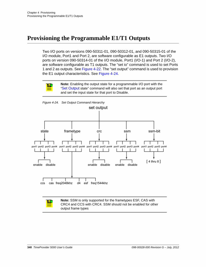
Chapter 4 ProvisioningProvisioning the Programmable E1/T1 Outputs
Provisioning the Programmable E1/T1 Outputs
Two I/O ports on versions 090-50311-01, 090-50312-01, and 090-50315-01 of the I/O module, Port1 and Port 2, are software configurable as E1 outputs. Two I/O ports on version 090-50314-01 of the I/O module, Port1 (I/O-1) and Port 2 (I/O-2), are software configurable as T1 outputs. The “set io” command is used to set Ports 1 and 2 as outputs. See Figure 4-22. The “set output” command is used to provision the E1 output characteristics. See Figure 4-24.
Figure 4-24. Set Output Command Hierarchy
Note: Enabling the output state for a programmable I/O port with the “Set Output state” command will also set that port as an output port and set the input state for that port to Disable.
Note: SSM is only supported for the frametypes ESF, CAS with CRC4 and CCS with CRC4. SSM should not be enabled for other output frame types
340 TimeProvider 5000 User’s Guide 098-00028-000 Revision G – July, 2012

Chapter 4 ProvisioningProvisioning the Programmable E1/T1 Outputs
If the output frame type supports SSM and SSM is enabled for the output port, then the output signal will contain the system SSM value. Table 4-19 shows the output SSM value based on the clock state of the TP5000.
2048kHz Frame TypeTo provision Port 1 as an output port with a frametype of 2048kHz, CRC disabled, SSM disabled, and to enable the port:
1. Login at the Admin or Config-user level.
2. Type set io port1 output and press Enter.
3. Type set output frametype port1 freq2048khz and press Enter.
4. Type set output crc port1 disable and press Enter.
5. Type set output ssm port1 disable and press Enter.
6. Type set output state port1 enable and press Enter.
Table 4-19. Output SSM-value vs. Clock State
Clock State Output SSM-value
Warm-up PQL=9 - Do not use for Sync (DUS)
Free-run PQL of oscillator
Fast-lock PQL of oscillator
Normal PQL of reference
Bridging Last PQL of reference
Holdover PQL of oscillator
Note: Enabling the output state for a programmable I/O port with the “Set Output state” command will also set that port as an output port and set the input state for that port to Disable.
098-00028-000 Revision G – July, 2012 TimeProvider 5000 User’s Guide 341

Chapter 4 ProvisioningProvisioning the Programmable E1/T1 Outputs
CCS Frame TypeTo provision Port 2 as an output port with a frametype of CCS, CRC enabled, SSM enabled, SSM-bit of 4, and to enable the port:
1. Login at the Admin or Config-user level.
2. Type set io port2 output and press Enter.
3. Type set output frametype port2 ccs and press Enter.
4. Type set output crc port2 enable and press Enter.
5. Type set output ssm port2 enable and press Enter.
6. Type set output ssm-bit port2 4 and press Enter.
7. Type set output state port2 enable and press Enter.
CAS Frame TypeTo provision Port 1 as an output port with a frametype of CAS, CRC enabled, SSM-bit of 4, and to enable the port:
1. Login at the Admin or Config-user level.
2. Type set io port1 output and press Enter.
3. Type set output frametype port1 cas and press Enter.
4. Type set output crc port1 enable and press Enter.
5. Type set output ssm port1 enable and press Enter.
6. Type set output ssm-bit port1 5 and press Enter.
7. Type set output state port1 enable and press Enter.
Note: Enabling the output state for a programmable I/O port with the “Set Output state” command will also set that port as an output port and set the input state for that port to Disable.
342 TimeProvider 5000 User’s Guide 098-00028-000 Revision G – July, 2012

Chapter 4 ProvisioningProvisioning the Programmable E1/T1 Outputs
Provisioning T1 Outputs
Use the following procedures to provision I/O-1 or I/O-2 (RJ-48 ports) as a T1 output.
1544kHz Frame TypeTo provision Port 1 as an output port with a frametype of 1544kHz, SSM disabled, and to enable the port:
1. Login at the Admin or Config-user level.
2. Type set io port1 output and press Enter.
3. Type set output frametype port1 freq1544khz and press Enter.
4. Type set output ssm port1 disable and press Enter.
5. Type set output state port1 enable and press Enter.
D4 Frame TypeTo provision Port 2 as an output port with a frametype of D4, SSM disabled, and to enable the port:
1. Login at the Admin or Config-user level.
2. Type set io port2 output and press Enter.
3. Type set output frametype port2 d4 and press Enter.
4. Type set output ssm port2 disable and press Enter.
5. Type set output state port2 enable and press Enter.
Note: The T1 ports on the 090-50314-01 version of the I/O module can also be configured as E1 and 2048 kHz inputs or outputs which meet the G.703 mask for impedance of 120 ohms, balanced.
Note: Enabling the output state for a programmable I/O port with the “Set Output state” command will also set that port as an output port and set the input state for that port to Disable.
098-00028-000 Revision G – July, 2012 TimeProvider 5000 User’s Guide 343
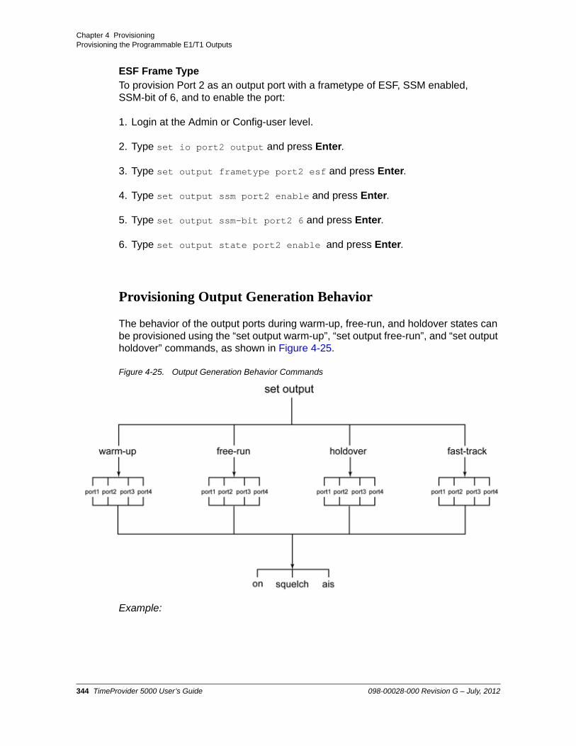
Chapter 4 ProvisioningProvisioning the Programmable E1/T1 Outputs
ESF Frame TypeTo provision Port 2 as an output port with a frametype of ESF, SSM enabled, SSM-bit of 6, and to enable the port:
1. Login at the Admin or Config-user level.
2. Type set io port2 output and press Enter.
3. Type set output frametype port2 esf and press Enter.
4. Type set output ssm port2 enable and press Enter.
5. Type set output ssm-bit port2 6 and press Enter.
6. Type set output state port2 enable and press Enter.
Provisioning Output Generation Behavior
The behavior of the output ports during warm-up, free-run, and holdover states can be provisioned using the “set output warm-up”, “set output free-run”, and “set output holdover” commands, as shown in Figure 4-25.
Figure 4-25. Output Generation Behavior Commands
Example:
344 TimeProvider 5000 User’s Guide 098-00028-000 Revision G – July, 2012

Chapter 4 ProvisioningProvisioning the Dedicated Outputs
To provision the port 1 output behavior as squelch for the warm-up state, AIS for the free-run state, and AIS for the holdover state:
1. Login at the Admin or Config-user level.
2. Type set output warm-up port1 squelch and press Enter.
3. Type set output free-run port1 ais and press Enter.
4. Type set output holdover port1 ais and press Enter.
5. Type set output fast-track port1 ais and press Enter.
Provisioning the Dedicated Outputs
Provisioning E1 Outputs
Port 3 and Port 4, the two dedicated output ports on the 090-50311-01 version of the I/O module, must be provisioned for the type of output signal. The “set output” command is used to provision the dedicated E1 output characteristics. See Figure 4-24.
2048kHz Frame TypeTo provision the dedicated output Port 3 for a frametype of 2048kHz, CRC disabled, SSM disabled, and to enable the port:
1. Login at the Admin or Config-user level.
2. Type set output frametype port3 freq2048khz and press Enter.
Note: For the 090-50312-01 and 090-50314-01 versions of the IOC card, Port 3 and Port 4 are configured as dedicated 1PPS and 10 MHz output ports, respectively. Use the “set output-10m” (Figure 4-24) and “set output-pps”(Figure 4-24) commands to provision the output generation behavior for Port 3 and Port 4 for these versions of the IOC card.
Note: Units that provide dedicated E1 outputs must be ordered from the factory; they cannot be reconfigured in the field.
Note: SSM is only supported for the frametypes ESF, CAS with CRC4 and CCS with CRC4. SSM should not be enabled for other output frame types
098-00028-000 Revision G – July, 2012 TimeProvider 5000 User’s Guide 345

Chapter 4 ProvisioningProvisioning the Dedicated Outputs
3. Type set output crc port3 disable and press Enter.
4. Type set output ssm port3 disable and press Enter.
5. Type set output state port3 enable and press Enter.
CCS Frame TypeTo provision output Port 4 with a frametype of CCS, CRC enabled, SSM enabled, SSM-bit of 6, and to enable the port:
1. Login at the Admin or Config-user level.
2. Type set output frametype port4 ccs and press Enter.
3. Type set output crc port4 enable and press Enter.
4. Type set output ssm port4 enable and press Enter.
5. Type set output ssm-bit port4 6 and press Enter.
6. Type set output state port4 enable and press Enter.
CAS Frame TypeTo provision output Port 4 with a frametype of CAS, CRC enabled, SSM-bit of 8, and to enable the port:
1. Login at the Admin or Config-user level.
2. Type set output frametype port4 cas and press Enter.
3. Type set output crc port4 enable and press Enter.
4. Type set output ssm port4 enable and press Enter.
5. Type set output ssm-bit port4 8 and press Enter.
6. Type set output state port4 enable and press Enter.
346 TimeProvider 5000 User’s Guide 098-00028-000 Revision G – July, 2012

Chapter 4 ProvisioningProvisioning the Dedicated Outputs
Provisioning Output Generation Behavior
The behavior of the dedicated output ports during warm-up, free-run, fast-track and holdover states can be provisioned using the “set output warm-up”, “set output free-run”, “set output fast-track” and “set output holdover” commands, as shown in Figure 4-25.
1. Login at the Admin or Config-user level.
2. Type set output warm-up port4 squelch and press Enter.
3. Type set output free-run port4 on and press Enter.
4. Type set output holdover port4 on and press Enter.
5. Type set output fast-track port4 squelch and press Enter.
Provisioning the 10MHz & 1PPS Outputs
The I/O module is also available with 1PPS and 10MHz dedicated output ports (p/n 090-50312-01 and 090-50314-01) rather than the dedicated E1 output ports (p/n 090-50311-01). The set output-pps command is used to provision the 1 PPS output. See Figure 4-26. The set output-10m command is used to provision the 10MHz output. See Figure 4-27. These commands can also be used to provision the behavior of the 10 MHz and 1PPS output ports during warm-up, free-run, and holdover states,
Figure 4-26. Set Output-PPS Commands
Note: Units that provide 1PPS and 10MHz outputs must be ordered from the factory; they cannot be reconfigured in the field. Port 3 provides 1PPS output and Port 4 provides 10 MHz output.
098-00028-000 Revision G – July, 2012 TimeProvider 5000 User’s Guide 347

Chapter 4 ProvisioningProvisioning the Dedicated Outputs
Figure 4-27. Set Output-10M Commands
Provisioning 1PPS PortTo enable the 1PPS output port and provision its output behavior as Squelch for the warm-up state, On for the free-run state, and On for the holdover state, use the following procedure:
1. Login at the Admin or Config-user level.
2. Type set output-pps warm-up squelch and press Enter.
3. Type set output-pps free-run on and press Enter.
4. Type set output-pps holdover on and press Enter.
5. Type set output-pps fast-track squelch and press Enter.
6. Type set output-pps state enable and press Enter.
Provisioning 10 MHz PortTo enable the 10 MHz output port and provision its output behavior as Squelch for the warm-up state, on for the free-run state, and Squelch for the holdover state, use the following procedure:
1. Login at the Admin or Config-user level.
2. Type set output-10m warm-up squelch and press Enter.
3. Type set output-10m free-run on and press Enter.
4. Type set output-10m holdover squelch and press Enter.
5. Type set output-10m fast-track squelch and press Enter.
6. Type set output-10m state enable and press Enter.
348 TimeProvider 5000 User’s Guide 098-00028-000 Revision G – July, 2012

Chapter 4 ProvisioningProvisioning TP 5000 for Expansion Shelf
Provisioning TP 5000 for Expansion Shelf
Verify that the TP 5000 and expansion are connected as shown in Figure 2-21.
It is critical that each expansion shelf be configured with a unique shelf ID (0-9) using the rotary switch on its front panel.
The following actions are required to provision the TP 5000 to support the operation of expansion shelves:
Enable ETH on TP 5000 IMC module’s DTI / ETH connector to allow communication with the expansion shelves
Enable DTI on the IMC module
Enable DTI on the I/O module
Verify Expansion Configuration
Symmetricom recommends that users verify the configuration of the DTI / ETH ports before provisioning.
1. Login at the Admin, Config, or User level.
2. Type show exp-if config imc and press Enter.
3. Type show exp-if config io and press Enter.
4. Type show exp-if config exp0 and press Enter.
Provisioning DTI / Ethernet Port on IMC Card
To EnableTo enable DTI and Ethernet on the IMC module, use the following procedure.
1. Login at the Admin or Config-user level.
2. Type set exp-if eth imc-exp state enable and press Enter.
3. Type set exp-if dti imc-exp enable and press Enter.
098-00028-000 Revision G – July, 2012 TimeProvider 5000 User’s Guide 349

Chapter 4 ProvisioningProvisioning TP 5000 for Expansion Shelf
To DisableIf there are no expansion shelves being used with the TP5000, Symmetricom recommends that the Ethernet port of the exp-if interface be disabled. The DTI port of this interface can also be disabled, however, it is not necessary to do so. Use the following procedure to disable the Ethernet and DTI ports of the exp-if interface on the IMC card.
1. Login at the Admin or Config-user level.
2. Type set exp-if eth imc-exp state disable and press Enter.
3. Type set exp-if dti imc-exp disable and press Enter.
Provisioning DTI Ports on IO Card
1. Login at the Admin or Config-user level.
2. Type set exp-if dti io-exp-1 enable and press Enter.
3. Type set exp-if dti io-exp-2 enable and press Enter.
Figure 4-28. DTI / Ethernet Port Command Hierarchy
350 TimeProvider 5000 User’s Guide 098-00028-000 Revision G – July, 2012

Chapter 4 ProvisioningProvisioning Expansion Shelf E1 / 1PPS+TOD Outputs
Provisioning Expansion Shelf E1 / 1PPS+TOD Outputs
The following actions are required to provision an expansion shelf:
Enable DTI for each expansion shelf
Provision output signals for each expansion shelf
Enable state(s) of output(s)
Provisioning DTI for an Expansion Shelf
1. Login at the Admin or Config-user level.
2. Type set exp-if dti exp0 in1 enable and press Enter.
3. Type set exp-if dti exp0 in2 enable and press Enter.
Provisioning E1 Output Signals for Expansion Shelf
The TP E30 expansion shelf supports three frame types for the E1 outputs: freq2048khz, CCS and CAS. The following parameters can also be configured:
CRC
SSM
SSM-bit
State
See Figure 4-29 for the hierarchy of commands to provision the expansion shelf E1 outputs.
The output generation behavior can be provisioned for fast-track, warm-up, free-run and holdover conditions. See Figure 4-30 for the hierarchy of commands to provision expansion shelf E1 output generation behavior.
098-00028-000 Revision G – July, 2012 TimeProvider 5000 User’s Guide 351

Chapter 4 ProvisioningProvisioning Expansion Shelf E1 / 1PPS+TOD Outputs
.
Figure 4-29. Expansion Shelf - Set Output-Exp Command Hierarchy
2048kHz Frame TypeTo provision the E1 output Port 3 on expansion shelf 1 (ID=exp0) for a frametype of 2048kHz, CRC disabled, SSM disabled, and to enable the port:
1. Login at the Admin or Config-user level.
2. Type set output-exp e1 frametype exp0 port3 frqe2048khz and press Enter.
3. Type set output-exp e1 crc exp0 port 3 disable and press Enter.
4. Type set output-exp e1 ssm exp0 port 3 disable and press Enter.
5. Type set output-exp e1 state exp0 port 3 enable and press Enter.
Note: SSM is only supported for the frametypes CAS with CRC4 and CCS with CRC4. SSM should not be enabled for other output frame types
If the outputs are enabled and the telecom outputs are provisioned to generate SSMs, the output SSM should be set to the LO's SSM value, e.g. TYPE I (TNC) or TYPE III (ST3E).
352 TimeProvider 5000 User’s Guide 098-00028-000 Revision G – July, 2012

Chapter 4 ProvisioningProvisioning Expansion Shelf E1 / 1PPS+TOD Outputs
CCS Frame TypeTo provision E1 output Port 4 on expansion shelf 1 (ID=exp0) with a frametype of CCS, CRC enabled, SSM enabled, SSM-bit of 6, and to enable the port:
1. Login at the Admin or Config-user level.
2. Type set output-exp e1 frametype exp0 port 4 ccs and press Enter.
3. Type set output-exp e1 crc exp0 port 4 enable and press Enter.
4. Type set output-exp e1 ssm exp0 port 4 enable and press Enter.
5. Type set output-exp e1 ssm-bit exp0 port 4 6 and press Enter.
6. Type set output-exp e1 state exp0 port 4 enable and press Enter.
CAS Frame TypeTo provision E1 output Port 4 on expansion shelf 1 (ID=exp0) with a frametype of CAS, CRC enabled, SSM-bit of 8, and to enable the port:
1. Login at the Admin or Config-user level.
2. Type set output-exp e1 frametype exp0 port 4 cas and press Enter.
3. Type set output-exp e1 crc exp0 port 4 enable and press Enter.
4. Type set output-exp e1 ssm exp0 port 4 enable and press Enter.
5. Type set output-exp e1 ssm-bit exp0 port 4 8 and press Enter.
6. Type set output-exp e1 state exp0 port 4 enable and press Enter.
Output Generation BehaviorOutput generation behavior can be configured independently for individual ports or the same behavior can be configured for all E1 ports on the specified expansion shelf.
1. Login at the Admin or Config-user level.
2. Type set output-exp e1 warm-up exp0 all squelch and press Enter.
3. Type set output-exp e1 free-run exp0 all ais and press Enter.
098-00028-000 Revision G – July, 2012 TimeProvider 5000 User’s Guide 353

Chapter 4 ProvisioningProvisioning Expansion Shelf E1 / 1PPS+TOD Outputs
4. Type set output-exp e1 holdover exp0 all on and press Enter.
5. Type set output-exp e1 fast-track exp0 all ais and press Enter.
Figure 4-30. Expansion Shelf - Set Output-Exp Generation Command Hierarchy
Provisioning 1PPS +TOD Outputs for Expansion Shelf
The state of the 1PPS+TOD outputs can be provisioned on the TP E30 E1/1PPS+TOD expansion shelf, as well as the output generation behavior for each 1PPS+TOD port.
See Figure 4-29 and Figure 4-30 for the hierarchy of commands to provision the expansion shelf 1PPS+TOD outputs.
State of Output PortsThe state of output ports can be configured independently for individual ports on the specified expansion shelf or all 1PPS+TOD ports can be set to the same state on the specified expansion shelf with a single command.
1. Login at the Admin or Config-user level.
2. Type set output-exp pps-tod state exp0 port 4 enable and press Enter.
354 TimeProvider 5000 User’s Guide 098-00028-000 Revision G – July, 2012

Chapter 4 ProvisioningProvisioning Expansion Shelf E1 / 1PPS+TOD Outputs
3. Type set output-exp pps-tod state exp1 all enable and press Enter.
Output Generation BehaviorOutput generation behavior can be configured independently for individual ports or the same behavior can be configured for all 1PPS+TOD ports on the specified expansion shelf.
1. Login at the Admin or Config-user level.
2. Type set output-exp pps-tod warm-up exp0 all squelch and press Enter.
3. Type set output-exp pps-tod free-run exp0 port 7 squelch and press Enter.
4. Type set output-exp pps-tod holdover exp0 all on and press Enter.
5. Type set output-exp pps-tod fast-track exp0 port 5 squelch and press Enter.
098-00028-000 Revision G – July, 2012 TimeProvider 5000 User’s Guide 355
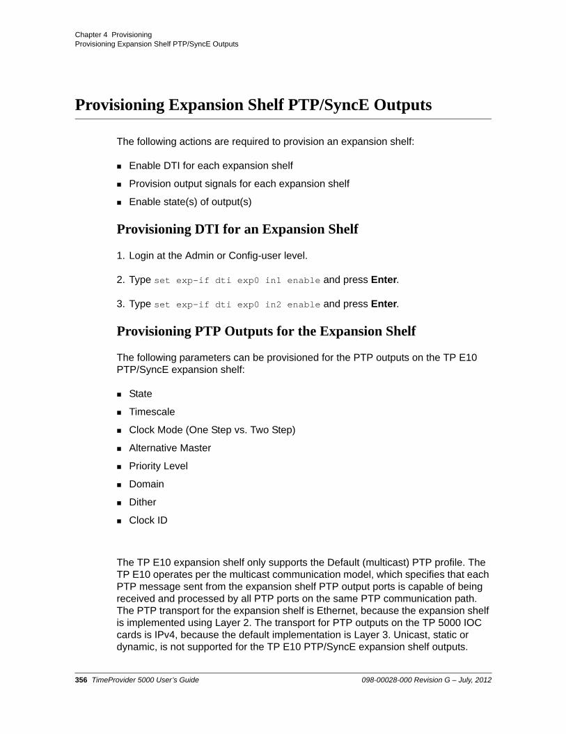
Chapter 4 ProvisioningProvisioning Expansion Shelf PTP/SyncE Outputs
Provisioning Expansion Shelf PTP/SyncE Outputs
The following actions are required to provision an expansion shelf:
Enable DTI for each expansion shelf
Provision output signals for each expansion shelf
Enable state(s) of output(s)
Provisioning DTI for an Expansion Shelf
1. Login at the Admin or Config-user level.
2. Type set exp-if dti exp0 in1 enable and press Enter.
3. Type set exp-if dti exp0 in2 enable and press Enter.
Provisioning PTP Outputs for the Expansion Shelf
The following parameters can be provisioned for the PTP outputs on the TP E10 PTP/SyncE expansion shelf:
State
Timescale
Clock Mode (One Step vs. Two Step)
Alternative Master
Priority Level
Domain
Dither
Clock ID
The TP E10 expansion shelf only supports the Default (multicast) PTP profile. The TP E10 operates per the multicast communication model, which specifies that each PTP message sent from the expansion shelf PTP output ports is capable of being received and processed by all PTP ports on the same PTP communication path. The PTP transport for the expansion shelf is Ethernet, because the expansion shelf is implemented using Layer 2. The transport for PTP outputs on the TP 5000 IOC cards is IPv4, because the default implementation is Layer 3. Unicast, static or dynamic, is not supported for the TP E10 PTP/SyncE expansion shelf outputs.
356 TimeProvider 5000 User’s Guide 098-00028-000 Revision G – July, 2012

Chapter 4 ProvisioningProvisioning Expansion Shelf PTP/SyncE Outputs
The “set ptp” command is used to provision PTP parameters for the TP E10 PTP/SyncE expansion shelf. See Figure 4-31 and Figure 4-32 for the hierarchy of the “set ptp” commands that apply to the TP E10 PTP/SyncE expansion shelf. SeeTable 4-11 for descriptions of the Common parameters and Table B-32 for defaults and ranges.
In multicast mode, there are no client leases or client limits. All delay requests will be responded to. There is no limit applied to the number of delay responses supported, other than the maximum capacity of the Ethernet link and the packet engine.
In multicast mode, the TP5000 creates a client list by examining the received PTP delay request messages. In order for a client to be reliably added to the client list and not removed, the TP5000 needs to receive several hundred delay request messages during the client timeout period. If delay requests are sent at a slow rate, then the client-timeout value must be increased. Since one-way PTP operation does not use delay request and delay response messages, the client list will not be populated in this mode.
Only one VLAN is supported in multicast mode. See Provisioning VLAN, on page 300 for details.
PTP Parameters for Expansion ShelfUse the following procedure to provision expansion shelf 0 for one-step clock mode, PTP timescale, alternate-master disabled, Priority 1 set to 2, Priority 2 set to 5, dither enabled, and the domain set to a value of 225:
1. Login at the Admin or Config-user level.
2. Type set ptp timescale exp0 ptp and press Enter
3. Type set ptp two-step exp0 disable and press Enter.
4. Type set ptp alternative-master exp0 disable and press Enter.
5. Type set ptp priority-1 exp0 2 and press Enter.
6. Type set ptp priority-2 exp0 5 and press Enter.
Note: The TP5000 requires a current license key to unlock the multicast addressing mode feature. Use the show license current command to display the current license.
Note: : If the Alternate Master mode is set to Enable, the alternate master flag will be set in the PTP messages. If the alternate master flag is set, the TP5000 will not run the Best Master Clock (BMC) algorithm and will stay in master mode.
098-00028-000 Revision G – July, 2012 TimeProvider 5000 User’s Guide 357

Chapter 4 ProvisioningProvisioning Expansion Shelf PTP/SyncE Outputs
7. Type set ptp dither exp0 enable and press Enter.
8. Type set ptp domain exp0 225 and press Enter.
9. Type set ptp clockid exp0 aa:bb:11:22:33:44:55:66 and press Enter.
10.Type set ptp state exp0 port1 enable and press Enter.
Figure 4-31. Set PTP Command Hierarchy for PTP Expansion Shelf
Figure 4-32. Set PTP Command Hierarchy for PTP Expansion Shelf (cont’d)
358 TimeProvider 5000 User’s Guide 098-00028-000 Revision G – July, 2012

Chapter 4 ProvisioningProvisioning Expansion Shelf PTP/SyncE Outputs
Provisioning SyncE Outputs for the Expansion Shelf
Synchronous Ethernet (syncE) provides a method of distributing timing using the physical layer of Ethernet devices. All intermediate nodes must have hardware and software support for syncE. SyncE is used to distribute frequency through the network. Synchronization Status Messaging (SSM) is passed between nodes in ESMC messages. This allows nodes to determine the quality level of the upstream node, to prevent timing loops, and also to reconfigure the timing path. The TP5000 provides the master function of providing synchronization via syncE .
Ethernet can be run in either asynchronous or synchronous modes. Electrical SFP do not support the transmission of timing and therefore are asynchronous. Optical SFP support synchronous operation and therefore can be used with syncE.
Normally, syncE nodes use the ESMC messages. However, if the downstream devices do not use the ESMC messages, then the messages can be disabled.
The system PQL value is normally sent in the QL -value (SSM) field in the ESMC message. If desired, this can be disabled and a value of DNU will be inserted in the ESMC message.
The user should set the appropriate SSM option with the set ssm-option command. This can be configured to either option 1 or option 2.
Figure 4-33 shows the command hierarchy for provisioning SyncE.
Two output QL modes are supported to accommodate network switch variations:
Unidirectional: SyncE output port supports a reduced SyncE, i.e. it transmits ESMC messages and ignores ESMC messages from the downstream SyncE NE. This is the default mode.
Bidirectional: SyncE output port checks the SSM of the received ESMC messages from the downstream NE. When the received SSM has the same QL value as the TP 5000 internal QL, SyncE output port will set the outgoing SSM to DNU. This mode accommodates SyncE switches that do not allow transmit and receive sides of a traffic port to have the same SSM value.
098-00028-000 Revision G – July, 2012 TimeProvider 5000 User’s Guide 359
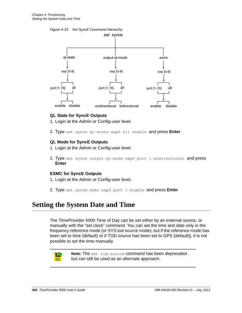
Chapter 4 ProvisioningSetting the System Date and Time
Figure 4-33. Set SyncE Command Hierarchy
QL State for SyncE Outputs1. Login at the Admin or Config-user level.
2. Type set synce ql-state exp0 all enable and press Enter
QL Mode for SyncE Outputs1. Login at the Admin or Config-user level.
2. Type set synce output-ql-mode exp0 port 1 bidirectional and press Enter
ESMC for SyncE Outputs1. Login at the Admin or Config-user level.
2. Type set synce esmc exp0 port 1 enable and press Enter
Setting the System Date and Time
The TimeProvider 5000 Time of Day can be set either by an external source, or manually with the “set clock” command. You can set the time and date only in the frequency reference mode (or SYS tod-source mode), but if the reference mode has been set to time (default) or if TOD source has been set to GPS (default)], it is not possible to set the time manually.
Note: The set tod-source command has been deprecated , but can still be used as an alternate approach.
360 TimeProvider 5000 User’s Guide 098-00028-000 Revision G – July, 2012

Chapter 4 ProvisioningProvisioning Alarms
Example
1. Login at the Admin or Config-user level (see Logging In, on page 275).
2. Type show ref and press Enter to check the reference mode.
3. Type set ref mode frequency and press Enter.
4. Type set clock date-time <value> and press Enter. Enter the value in format yyyy-mm-dd,hh:mm:ss.
5. Type sync tod-source now and press Enter.
Provisioning Alarms
This section describes the commands used to provision and manage alarms in the TimeProvider 5000. The user can provision the alarms to be enabled or disabled and set thresholds to turn the alarms on and off. For a list of all alarms, see Appendix A, System Messages.
Software commands allow you to perform the following:
Provision the severity level
Provision the alarm (enable or disable)
Show current alarm settings
Show current alarms
Display alarm status
Alarms are also indicated by LEDs on the IOC and IMC modules.
Note: Disabling an input port will clear all alarms and events related to the port.
098-00028-000 Revision G – July, 2012 TimeProvider 5000 User’s Guide 361

Chapter 4 ProvisioningProvisioning Alarms
Figure 4-34. Set Alarm-Config Commands
Disabling Specific Alarms
The Set Alarm-Config command allows you to enable or disable specified alarms.
Example
To disable the GNSS/GPS antenna open-circuit alarm (alarm #13), enter the following:
1. Login at the Admin or Config-user level (see Logging In, on page 275).
2. Type set alarm-config state alarm 13 disable and press Enter.
Showing Current Alarm Settings
The Show Alarm-Config command displays the set and clear alarm thresholds for every alarm type.
Example
362 TimeProvider 5000 User’s Guide 098-00028-000 Revision G – July, 2012

Chapter 4 ProvisioningProvisioning Alarms
To display the configuration for all alarm types, enter the following:
1. Type show alarm-config and press Enter.
Showing Current Alarms
The Show Alarm command displays all current alarms.
Example
To display a list of all current alarms enter the following:
1. Type show alarm and press Enter.
Displaying Alarm and Unit Status
The Show Status command displays the system status information as follows:
Assigned System Name
Uptime for the IMC card and IOC card
System date and time
Number of standing system alarms
Active IOC card
Standby IOC card
Currently selected reference mode
Reference Input
Clock status of active IOC card
PTP Service Mode (GrandMaster or Probe)
Expansion shelf connections
Example
Note: Probe mode is only available with the TP5000 platform as part of the TimeAnalyzer 7x00.
098-00028-000 Revision G – July, 2012 TimeProvider 5000 User’s Guide 363
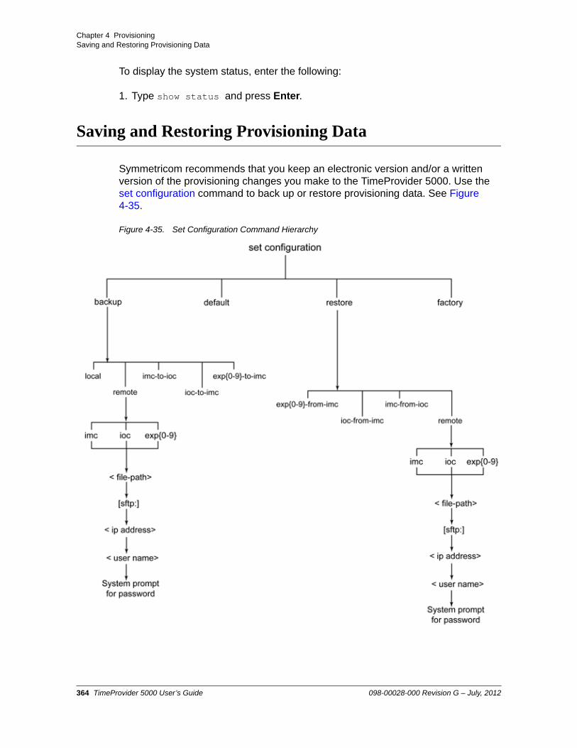
Chapter 4 ProvisioningSaving and Restoring Provisioning Data
To display the system status, enter the following:
1. Type show status and press Enter.
Saving and Restoring Provisioning Data
Symmetricom recommends that you keep an electronic version and/or a written version of the provisioning changes you make to the TimeProvider 5000. Use the set configuration command to back up or restore provisioning data. See Figure 4-35.
Figure 4-35. Set Configuration Command Hierarchy
364 TimeProvider 5000 User’s Guide 098-00028-000 Revision G – July, 2012

Chapter 4 ProvisioningSaving and Restoring Provisioning Data
Backing up Provisioning Data
The configuration is automatically backed up one minute after a configuration change.
Example 1
To backup up the current configuration immediately, enter the following:
1. Type set configuration backup local and press Enter.
Example 2
To backup up the current configuration of the IMC card to the active IOC card, enter the following:
1. Type set configuration backup imc-to-ioc and press Enter.
Example 3
To backup up the current configuration of expansion shelf with ID=3 to the IMC card, enter the following:
1. Type set configuration backup exp3-to-imc and press Enter.
Example 4
To back up the configuration data of the active IOC to a remote site, which is an SFTP server with the IP address of 172.16.33.33, id: tp5000, password: backup, with a file name for backup data of “tp5k_ioc_backup.txt”:
1. Type set configuration backup remote ioc tp5k_ioc_backup.txt sftp:172.16.33.33 tp5000 and press Enter.
2. The system will prompt for the password. Enter the password and press Enter.
Note: For remote storage, path names should be specified as appropriate for the FTP/SFTP server and the operating system on which it is running. This includes whether the entire path should be specified and whether "/" or "\" characters should be used.
098-00028-000 Revision G – July, 2012 TimeProvider 5000 User’s Guide 365

Chapter 4 ProvisioningSaving and Restoring Provisioning Data
Example 5
To back up the configuration data for an expansion shelf with ID=6 to a remote site, which is an SFTP server with the IP address of 172.16.33.33, id: tp5000, password: backup, with a file path for backup data of “c:\sftp\tp5k_exp6_backup.txt”:
1. Type set configuration backup remote exp6 c:\sftp\tp5k_exp6_backup.txt sftp:172.16.33.33 tp5000 and press Enter.
2. The system will prompt for the password. Enter the password and press Enter.
366 TimeProvider 5000 User’s Guide 098-00028-000 Revision G – July, 2012

Chapter 4 ProvisioningSaving and Restoring Provisioning Data
Restoring Provisioning Data
Example 1
To change the current configuration to factory default while preserving user and IP information, enter the following:
1. Type set configuration default and press Enter.
Example 2
To change the current configuration to the factory default, enter the following:
1. Type set configuration factory and press Enter.
Example 3
To restore the expansion shelf with ID=3 with its stored configuration from the IMC card, enter the following:
1. Type set configuration restore exp3-from-imc and press Enter.
Example 4
To restore the configuration data with a file name of tp5k_ioc_backup.txt for the active IOC from a remote site, which is an SFTP server with the IP address of 172.16.33.33, id: tp5000, password: backup:
1. Type set configuration restore remote ioc c:\sftp\tp5k_ioc_backup.txt sftp:172.16.33.33 tp5000 and press Enter.
2. The system will prompt for the password. Enter the password and press Enter.
Notes: Setting the configuration to default will not overwrite the user login information or the IP address of MGMT port of IMC. Setting the configuration to factory will overwrite the user login information and return the IP address of MGMT port of IMC to the factory set address.
Note: For remote storage, path names should be specified as appropriate for the FTP/SFTP server and the operating system on which it is running. This includes whether the entire path should be specified and whether "/" or "\" characters should be used.
098-00028-000 Revision G – July, 2012 TimeProvider 5000 User’s Guide 367

Chapter 4 ProvisioningSaving and Restoring Provisioning Data
Example 5
To restore the configuration data file tp5k_exp6_backup.txt back to an expansion shelf with ID=6 from the SFTP server with the IP address of 172.16.33.33, id: tp5000, password: backup:
1. Type set configuration restore remote exp6 tp5k_exp6_backup.txt sftp:172.16.33.33 tp5000 and press Enter.
2. The system will prompt for the password. Enter the password and press Enter.
368 TimeProvider 5000 User’s Guide 098-00028-000 Revision G – July, 2012

Chapter 4 ProvisioningProvisioning for SNMP
Provisioning for SNMP
The Simple Network Management Protocol (SNMP) is an application layer protocol that allows you to manage network devices. SNMP is based on a client-server query-response mode that requires an Ethernet connection. A manager application (software installed on a computer) is the client generating the queries, and an agent (software on the TimeProvider 5000) is the server generating responses. The TimeProvider 5000 SNMP supports all existing functions. TimeProvider 5000 supports SNMPv2c and SNMPv3.
If SNMP is present, port 161 becomes the port of standard SNMP interactive communications and port 162 becomes the trap port.
SNMP functionality is provisioned on the TP5000 using the CLI command “set snmp” (see Figure 4-36).
The TimeProvider 5000 MIB has one SNMP container OID for alarms and one SNMP container OID for events. All alarms are reported from the same OID. The object tp5000TrapAlarm, 1.3.6.1.4.1.9070.1.2.4.6.2.2.3, is the container OID used to report alarms via SNMP trap. All events are reported from the same OID. The object tp5000TrapEvent, 1.3.6.1.4.1.9070.1.2.4.6.2.2.4, is the container OID used to report events via SNMP trap
Each container contains the following sub-info in its own OID:
Module ID (IMC, IOC1, IOC2)
Alarm/Event ID
Date&Time
Severity
Alarm/Event Description
Note: The SNMP feature can either be ordered in a new system, or added to a previously ordered system as a field upgrade. Contact your Symmetricom representative for more information.
Note: For redundant IOC systems, the IOC1 configuration is used for both IOC cards, regardless of which IOC is active.
098-00028-000 Revision G – July, 2012 TimeProvider 5000 User’s Guide 369

Chapter 4 ProvisioningProvisioning for SNMP
The elements are defined in the activeAlarmTable and activeEventTable objects. The object activeAlarmTable, 1.3.6.1.4.1.9070.1.2.4.6.2.2.1, is a table containing the active alarms and can be used to poll the active alarms. The object activeEventTable, 1.3.6.1.4.1.9070.1.2.4.6.2.2.2, is a table containing the active events and can be used to poll the active events
The Alarm/Event ID element should be used to determine which alarm or event was generated. Alarm and Event IDs are listed in Appendix A, System Messages.
Enabling the SNMP License
SNMP is an optional feature on the TP5000. It must be enabled. To enable this feature, use the “set license add” command with the 40-character key printed on the Symmetricom-issued certificate for the unit.
Example
To enable the SNMP option, with a license key of “ABCDEFGHIJ1234567890KLMNOPQRST0987654321”:
1. Type set license add then press Enter.
2. Enter the license key when prompted by the TP5000 and press Enter.
License key: ABCDEFGHIJ1234567890KLMNOPQRST0987654321
Note: If the user has a 6-character key, the “set option” command is used to enter the key.
370 TimeProvider 5000 User’s Guide 098-00028-000 Revision G – July, 2012

Chapter 4 ProvisioningProvisioning for SNMP
Figure 4-36. Set SNMP Commands
Selecting MIB Versions
Use the “set snmp trap-mib” and “set snmp sys-obj-mib” commands to select the MIB version to be used for traps and system, respectively.
Example:
To select the v2.0 trap MIB and v2.0 sys-obj MIB.:
1. Type set snmp trap-mib 2.0 then press Enter.
2. Type set snmp sys-obj-mib 2.0 then press Enter.
Adding or Deleting a Manager IP Address
Use the “set snmp add manager” command to add a manager IP address. Use the “set snmp delete manager” command to delete a manager IP address. The TP5000 will support a maximum of 3 manager IP addresses.
Example:
098-00028-000 Revision G – July, 2012 TimeProvider 5000 User’s Guide 371

Chapter 4 ProvisioningProvisioning for SNMP
To add the SNMP manager IP address 192.100.100.100, using an engineID 0x12345678901234567890:
1. Type set snmp add manager 192.100.100.100 engineid 0x12345678901234567890 then press Enter.
Provisioning to Generate v2 Traps
Use the “set snmp trapversion” command to provision the trap version to v2.
The default trap version is v2. By default, therefore, the TP5000 will generate v2 traps if the SNMP option is activated.
Example:
1. Type set snmp trapversion 2 then press Enter.
Provisioning to Generate v3 Traps
Use the “set snmp trapversion” command to provision the trap version to v3.
Example
1. Type set snmp trapversion 3 then press Enter.
Adding and Removing v2 Communities
Use the “set snmp add v2-community” command to add a SNMP v2 community. Use the “set snmp delete v2-community” command to remove an existing SNMP v2 community. The TP5000 will support a maximum of 10 v2 communities.
Example
To add a v2 community named “tech27”, with a security level of “read-only” and remove an existing v2 community named “bob321”:
1. Type set snmp add v2-community tech27 securlvl read-only then press Enter.
2. Type set snmp delete v2-community bob321 then press Enter
Note: To use v2 communities, the v2 state must be set to Enable using the command “set snmp state-v2 enable”.
372 TimeProvider 5000 User’s Guide 098-00028-000 Revision G – July, 2012

Chapter 4 ProvisioningProvisioning for SNMP
Adding and Removing SNMP v3 Users
SNMPv3 provides additional security features not available in SNMPv2c. In addition to the functions of SNMPv2c, SNMPv3 allows user and trapuser levels that are based on authentication and privacy settings. The authentication algorithm is either HMAC-SHA-1-96 or MD5, with a key up to 32 characters in length. The privacy settings are based on either the CBC-DES or AES encryption standard, with a with a key up to 32 characters in length. All keys are uppercase.
Use the “set snmp add user” command to add a v3 user. Use the “set snmp delete user” command to remove an existing v3 user. The TP5000 will support a maximum of 10 v3 users.
Example - Add User
To add a user named “test12”, with a security level of “priv”, with a 20-character MD5 authentication key “123456789ABCDEFGHIJK” and a 16-character DES privacy key “ABCDEFG123456789”:
1. Type set snmp add user test12 securlvl priv then press Enter.
2. Enter MD5 at the authentication protocol prompt.
3. Enter 123456789ABCDEFGHIJK at the authentication key prompt
4. Enter DES at the privacy protocol prompt
5. Enter ABCDEFG123456789 at the privacy key prompt
Example - Remove User
Note: Do not use spaces within keys. Only characters {a-z,A-Z,0-9,! ( ) - _ . ? ~ * @ ^ + = : / %} are accepted for SNMP authentication or privacy keys.
098-00028-000 Revision G – July, 2012 TimeProvider 5000 User’s Guide 373

Chapter 4 ProvisioningProvisioning for SNMP
To remove an existing user named “dave123”:
1. Type set snmp delete user dave123 then press Enter
Adding and Removing SNMP v3 Trap Users
Use the “set snmp add user” command to add a v3 trap user. Use the “set snmp delete trapuser” command to remove an existing v3 trap user. The TP5000 will support a maximum of 3 v3 trap users.
Example - Add Trap User
To add a trap user named “test12” with a security level of “priv”, with the 20-character MD5 authentication key “123456789ABCDEFGHIJK” and 16-character DES privacy key “ABCDEFG123456789”:
1. Type set snmp add trapuser test12 securlvl priv then press Enter.
2. Enter MD5 at the authentication protocol prompt.
3. Enter 123456789ABCDEFGHIJK at the authentication key prompt
4. Enter DES at the privacy protocol prompt
5. Enter ABCDEFG123456789 at the privacy key prompt
Example - Remove Trap User
To remove an existing trapuser named “dave123”:
1. Type set snmp delete trapuser dave123 then press Enter
Note: In order to access trap information, a trap user must also be added as a user. The same name, authentication protocol, authentication key, privacy protocol, and privacy key must be used for both the user and trap user.
374 TimeProvider 5000 User’s Guide 098-00028-000 Revision G – July, 2012

Chapter 5 Operating
This chapter provides guidelines for operating the TimeProvider 5000.
In This Chapter
Logging In And Out
Adding And Deleting Users
Saving Present Configuration To Non-volatile Memory
Restoring Default Configuration
Determining Status
Forcing Unit To Send New Time in Time Reference Mode
Switching Active And Standby IOC Cards
Displaying Alarms Log
Displaying Events Log
Managing PTP Clients
– Configuring PTP Clients
– Monitoring PTP Client Performance
– Monitoring PTP Client Alarm / Event Information
– Upgrading PTP Client Firmware
098-00028-000 Revision G – July, 2012 TimeProvider 5000 User’s Guide 375

Chapter 5 OperatingLogging In And Out
Logging In And Out
The default administrator user name is “admin” with password “symmadmin**”
To login:
tp5000> loginUser: <user name>Password: <password>
To logout:
tp5000> logout
Adding And Deleting Users
Only a security-level admin user can add or delete users.
Users can be added or removed with the following commands:
set user add <username>
set user delete <username>
Saving Present Configuration To Non-volatile Memory
Use the following commands to save IMC module settings to the IOC memory and to save the active IOC module settings in the IMC memory:
set configuration backup imc-to-ioc
set configuration backup ioc-to-imc
Restoring Default Configuration
The user can restore the TimeProvider 5000 to Symmetricom factory default values in two ways. The default mode preserves user login information and IP addresses of the MGMT port of the IMC, and is set with the following command:
set configuration default
The factory mode overwrites all user login information and IP addresses of the MGMT port of the IMC, and is set with the following command:
set configuration factory
376 TimeProvider 5000 User’s Guide 098-00028-000 Revision G – July, 2012

Chapter 5 OperatingDetermining Status
Determining Status
show alarm (displays presently active alarms)
show gps status (displays GPS information)
show inventory (displays details for IMC and IOC cards)
show status (displays general status of unit)
Forcing Unit To Send New Time in Time Reference Mode
The user may need to manually sync the IOC time and phase to the time reference’s time and phase if there is any difference. After the reference mode is changed to time and the system is locked to the reference, the TP5000 response depends on whether Auto-Sync is enabled and whether the TP5000 has left warm-up. The possible system responses are shown in Table 5-1 below.
Note: The "sync tod-source" command forces the TimeProvider 5000 to immediately start using the new reference time. The use of this command should be carefully planned since it may cause jitter in the 1PPS output of the TimeProvider 5000.
Table 5-1. Force Unit to Send New TIme vs. Auto Sync
Condition of TP5000
Auto-Sync State
System Response
Unit is still in warm-up Enabled Time and phase will automatically sync to the time reference
Unit is still in warm-up Disabled Time and phase will automatically sync to the time reference
Unit has left warm-up Enabled Time and phase will automatically sync to the time reference
Unit has left warm-up Disabled Alarm ID #8 (Manual sync IOC time to IMC required) will be generated. Use the command “sync tod-source now” to manually sync IOC time and phase to the time reference and clear the alarm
098-00028-000 Revision G – July, 2012 TimeProvider 5000 User’s Guide 377

Chapter 5 OperatingSwitching Active And Standby IOC Cards
Switching Active And Standby IOC Cards
Active and standby IOC cards may be switched automatically or manually. See Appendix D, Redundant IOC Cards for additional details.
Manually Switching IOC Cards
Use the “set ioc-state” command to switch the standby IOC module to become the active module. IOC1 refers the IOC module to the left of the IMC and IOC2 refers to the IOC module to the right of the IMC, as shown in Figure 5-1 below..
Figure 5-1. IOC1 and IOC2 Modules
Example:
If IOC1 is the active card, IOC2 is the standby card. This example demonstrates switching IOC2 to be the active card, then using the “show ioc-state” command to verify the switch.
tp5000> set ioc-state ioc2 active
tp5000> show ioc-state
Automatic IOC Card Switches
The active card continually assesses its own health level compared with the health level of the standby card. If the active card should become unhealthier than the standby card, then a switch will occur. See Causes of Switchovers Between IOC Cards, on page 501.
Note: Switchover to the standby IOC will be prohibited if the standby IOC has alarms of higher severity than the active IOC or if the standby IOC is still in warm-up. Check system status and alarms if the command fails.
378 TimeProvider 5000 User’s Guide 098-00028-000 Revision G – July, 2012

Chapter 5 OperatingDisplaying Logs
If the detected condition of an IOC card is of "fail" level, the card is taken completely out of service. If the failed card is the active card at the time of the failure, the standby card then becomes active. The failed card will not become standby because it is now nonfunctional. This situation then becomes analogous to the user removing the active IOC module, which forces a switchover. The active IOC module will go to fail regardless of the state (or existence) of the other IOC module.
Removing the active IOC card also forces an automatic switchover to the standby card.
Impact of IOC Card Switches on IO Card Outputs
Switching active and standby IOC cards will have the following impact on the various output signals on the IO card.
During switchover, the PTP outputs may be interrupted for a maximum of 10 seconds.
All continuous outputs, 10MHz, 1PPS, and E1, will not exhibit any loss of signal during switchover, but may exhibit phase movement of up to 240 ns.
Displaying Logs
This section describes the commands used to display the TP5000 alarm and event logs.
Displaying Alarms Log
The “show log alarm” command displays all local alarms in the alarm log in chronological order (first in - first out).
Example
1. Type show log alarm and press Enter.
Displaying Events Log
The “show log event” command displays all local events in the event log in chronological order (first in - first out). The event log contains the 1000 most recent alarmed and non-alarmed events.
Note: Removing the active card is not recommended. Before removing the active card, manually switch the active IOC card to standby using the procedure in the section above.
098-00028-000 Revision G – July, 2012 TimeProvider 5000 User’s Guide 379

Chapter 5 OperatingRestarting the TimeProvider 5000
Example
1. Type show log event and press Enter.
Restarting the TimeProvider 5000
The system can be restarted via the reboot system command. Since reference output signals will be lost, it is not recommended to restart the entire system unless required. Only the admin user can issue the reboot command. The reboot imc command restarts the IMC card, and no output will be lost. If the system has two IOC modules, each IOC can be rebooted separately to preserve the output.
Example:
1. Type reboot imc and press Enter.
2. Type reboot ioc1 and press Enter.
3. Type show status and press Enter to check the status of IOC1.
4. After IOC1 has entered the standby state, type reboot ioc2 and press Enter (if applicable).
380 TimeProvider 5000 User’s Guide 098-00028-000 Revision G – July, 2012

Chapter 5 OperatingManaging PTP Clients
Managing PTP Clients
The TimeProvider 5000 GrandMaster supports four different aspects of PTP management for TimeProvider 500 clients. The “set ptp-node” command is used to provision the acceptable master clocks, reboot, and upgrade the firmware for TP500 clients through the TP5000 GrandMaster. See Figure 5-2. The “show ptp-node status” command is used to monitor TP500 client performance. The TimeProvider 5000 also offers a means to monitor alarm and event information for TimeProvider 500 clients using Simple Network Management Protocol (SNMP).
Figure 5-2. PTP Management Commands
098-00028-000 Revision G – July, 2012 TimeProvider 5000 User’s Guide 381

Chapter 5 OperatingManaging PTP Clients
Configuring PTP Clients
The TimeProvider 5000 Grandmaster provides a way to perform limited configuration of PTP clients (TimeProvider 500 clients only). This consists of allowing a user to set the acceptable master clocks for a client via PTP messages issued from the TP5000.
The TimeProvider 500 PTP client supports a capability to select from one of two master clocks. Use of this feature is easily enabled by providing target addresses for two master clocks. When both are configured to non-zero IP addresses, the TimeProvider 500 will attempt to establish PTP flow with both. If a flow problem persists, or no flow can established at all with one of the candidate masters, then the other one will be used as long as it has acceptable PTP flow.
How to Set PTP Client Acceptable Master ClocksThe example is for Port 1 on the active IOC card, with the following additional parameters:
– Client IP Address: 192.168.1.220
– Acceptable Master 1 IP Address: 192.168.12.23
– Acceptable Master 1 Priority: 5
– Acceptable Master 2 IP Address: 192.168.12.30
– Acceptable Master 2 Priority: 20
– VLAN None
1. Login at the Admin level (see Logging In And Out, on page 376).
2. Type set ptp-node acc-master IOC-1 address 192.168.1.220 master1ip 192.168.12.23 priority 5 master2ip 192.168.12.30 priority 20 and press Enter.
382 TimeProvider 5000 User’s Guide 098-00028-000 Revision G – July, 2012

Chapter 5 OperatingManaging PTP Clients
Monitoring PTP Client Performance
The TimeProvider 5000 Grandmaster provides a way to monitor performance of clients (TimeProvider 500 clients only). The “show ptp-node status” command allows the user to view the current status of a specific client. Figure 5-3 shows a typical status response from a TP500 client.
Figure 5-3. Client Status Information
098-00028-000 Revision G – July, 2012 TimeProvider 5000 User’s Guide 383

Chapter 5 OperatingManaging PTP Clients
How to Check Client StatusThe example is for Port 1 on the active IOC card, with Client IP Address of 192.168.1.200 and no VLAN.
1. Login at the Admin level, Config or User level (see Logging In And Out, on page 376).
2. Type show ptp-node status IOC-1 address 192.168.1.200 and press Enter.
See Figure 5-3 for a typical response for a status request from a TP500 client.
Monitoring PTP Client Alarm / Event Information
TimeProvider 500 IEEE-1588 clients pass alarm and event information to the TimeProvider 5000 IEEE-1588 Grandmaster via PTP communication. Event IDs 68 through 70 correspond to TP500 client alarms based on severity (user -configurable at the client level). Event IDs 71 and 72 are indications of TP500 client events. See Table A-1 and Table A-2. The TimeProvider 5000 offers a means to monitor alarm and event information for TimeProvider 500 clients via Simple Network Management Protocol (SNMP), which is available as an option. The TimeProvider 5000 supports SNMPv2c and SNMPv3. Client alarm and event information is not accessible through the TP5000 with CLI commands..
SNMP is an application layer protocol that allows you to manage network devices. SNMP is based on a client-server query-response mode that requires an Ethernet connection. A manager application (software installed on a computer) is the client generating the queries, and an agent (software on the TimeProvider 5000) is the server generating responses. The TimeProvider 5000 SNMP supports most existing functions.
In order to manage PTP client alarms and events with the TP5000, the alarms and events must be monitored as SNMP traps. SNMP traps are configured using the SNMP manager application. Consult the documentation for the SNMP manager application for details about how to set up traps.
Note: The SNMP feature can either be ordered in a new system, or added to a previously ordered system as a field upgrade. Contact your Symmetricom representative for more information.
Note: If SNMP is activated on the TP5000, port 161 becomes the port of standard SNMP interactive communications and port 162 becomes the trap port.
384 TimeProvider 5000 User’s Guide 098-00028-000 Revision G – July, 2012

Chapter 5 OperatingManaging PTP Clients
Upgrading PTP Client Firmware
The TimeProvider 5000 Grandmaster provides a way to remotely upgrade the firmware of PTP clients (TimeProvider 500 clients only). See set ptp-node, on page 223 for command details.
How to Upgrade Client Firmware1. Login at the Admin level (see Logging In And Out, on page 376).
2. Type set ptp-node upgrade IOC-y address <client_ip> [vlan-id <vlan>] <filepath> FTP:<server_ip> <user_name> and press Enter.
Example - FTP: For an FTP server with IP address 192.168.5.64, no VLAN, Port 1 of the active IOC card, client IP address of 192.168.1.200, a user name of “user1” on the FTP server, and an upgrade file named “Maincode.bin” the command is:
set ptp-node upgrade ioc-1 address 192.168.1.200 Maincode.bin ftp:192.168.5.64 user1
3. When prompted, enter the password for the server. The new software is loaded into the client.
4. Type set ptp-node reboot IOC-1 address 192.168.1.220 and press Enter to reboot the client.
The firmware update will not be implemented until after the client has been rebooted.
Note: TP500 clients send autonomous messages about the upgrade process status at the start and finish of the process. These messages will generate SNMP traps from the TP5000 if the SNMP option is activated and enabled for the TP5000, and if SNMP traps are configured.
098-00028-000 Revision G – July, 2012 TimeProvider 5000 User’s Guide 385

Chapter 5 OperatingManaging PTP Clients
386 TimeProvider 5000 User’s Guide 098-00028-000 Revision G – July, 2012

Chapter 6 Maintenance and Troubleshooting
This chapter describes maintenance and troubleshooting procedures for the TimeProvider 5000.
In This Chapter
Preventive Maintenance
Safety Considerations
ESD Considerations
Troubleshooting
– Diagnosing the IOC - Reading LED Conditions
– Diagnosing the IMC - Reading LED Conditions
Repairing the TimeProvider 5000
– Removing the IOC
– Replacing the IOC
– Replacing the IMC
Upgrading the Firmware
– TP5000 Upgrade - Loss of Outputs
– TP5000 with Redundant IOC Modules v1.2.3 - No Loss of Outputs
– TP5000 with Redundant IOC Modules v1.1.8 - No Loss of Outputs
– Upgrading an Expansion Shelf
Downgrading the Firmware
TimeProvider 5000 Part Numbers
Returning the TimeProvider 5000
User’s Guide Updates
Contacting Technical Support
098-00028-000 Revision G – July, 2012 TimeProvider 5000 User’s Guide 387

Chapter 6 Maintenance and TroubleshootingPreventive Maintenance
Preventive Maintenance
The TimeProvider 5000 requires minimal preventive maintenance. Ensure the unit is not exposed to hazards such as direct sunlight, open windows, water, or extreme heat. See Environmental Requirements, on page 59, for electromagnetic compatibility conditions that may cause damage.
Table 6-1 lists preventive maintenance measures to be performed periodically. Do not disassemble components just for the purpose of inspection.
Safety Considerations
Follow your company’s safety guidelines and policies when working on or around live equipment.
ESD Considerations
Maintenance personnel should wear ESD wrist straps when installing or working on all TimeProvider 5000 equipment and modules. Plug the user-supplied wrist strap into the TimeProvider 5000. Place IMC and IOC modules into static-free bags when not in use.
Caution: To avoid electromagnetic discharge damage to the circuitry, never attempt to vacuum the TimeProvider 5000.
Caution: To avoid damage, under no circumstances should the interior chassis of the TimeProvider 5000 be allowed to come in contact with water.
Table 6-1. Preventive Maintenance
Item Inspection Corrective Action Interval
Chassis Inspect for dirt or foreign material
Clean the exterior of chassis with a soft dry cloth
Periodically
Cables Inspect for pinched, worn or damaged cable
Replace pinched, worn or damaged cable at the first opportunity
Periodically
Connectors Inspect for loose or damaged connector
Tighten loose connectors. If damaged, replace the connector and/or cable at the first opportunity
Periodically
388 TimeProvider 5000 User’s Guide 098-00028-000 Revision G – July, 2012

Chapter 6 Maintenance and TroubleshootingTroubleshooting
Troubleshooting
Symptoms, LEDs, and System Messages can all be very helpful in troubleshooting the TP5000. Use the “show alarm” and “show event” commands to view system messages.
Table 6-2 presents troubleshooting information for the TP5000 based on symptoms. Table 6-3 presents diagnostic information for the IOC card using on front panel LEDs. Table 6-4 presents diagnostic information for the IMC card based on front panel LEDs. See Table A-1 in Appendix A, System Messages for Event IDs, system messages and associated corrective actions.
Table 6-2. Troubleshooting Symptoms
Symptom Probable CauseTroubleshooting Procedure /
Corrective Action
No LED lit on any module No power to unit Check power supply
Check to ensure that UPS (if applicable) is operating correctly
Both A and B fuses on the branch over-current protection unit are blown
Remove both fuses and replace
Loss of ground Re-attach ground wires
Loose power cabling to unit
Check that power cables to unit are securely fastened
Chassis is faulty Contact Symmetricom Global Services
No PTP flow between TP5000 Grandmaster and client
(If LED for port is OFF:)
Cable connections Check the cable connections and SFP connections.
Verify that SFP connector models are recommended and supported.
Ethernet Auto Negotiation settings
Check that either Ethernet Auto Negotiation is enabled or that speed has been set to a compatible level with the connecting network element (show eth config command).
Make sure that only full-duplex network devices are used. The TP5000 does not support half-duplex devices, such as hubs, for PTP connections.
098-00028-000 Revision G – July, 2012 TimeProvider 5000 User’s Guide 389

Chapter 6 Maintenance and TroubleshootingTroubleshooting
No PTP flow between TP5000 Grandmaster and client
(If LED for port is ON and ping to client is unsuccessful:)
VLAN / non-VLAN configuration is incorrect
or
IP address configuration is incorrect
Verify that IP configuration is correct with "show ip config ioc1"
Verify that VLAN configuration is correct with “show vlan-config ioc1”
Verify that IP status is correct with "show ip status ioc"
If status does not look correct, restart interface with "set ip ioc1-1 restart" or "set ip ioc1-2 restart", as appropriate
No PTP flow between TP5000 Grandmaster and client
(If LED for port is ON and ping to client is successful:)
Client configuration for acceptable Grandmaster is incorrect
Check acceptable Grandmaster setting of client.
PTP state set to Disable Change PTP state to Enable with “set ptp state” command for the port.
PTP Max Clients setting for TP5000 exceeded
If number of clients exceeds max setting for TP5000, extra clients are ignored. Change max clients setting with “set ptp max-client” command
PTP domain setting for GM does not match client’s domain
Verify domain setting for GM matches the domain setting for the client. Check GM domain setting with “show ptp-config common” command for the port.
PTP Unicast - Dynamic negotiation disabled on GM , with Unicast -Dynamic clients
Check Unicast - Dynamic negotiation setting of GM with “show ptp-config common” command for the port. Use the “set ptp unicast dynamic negotiate ioc1-[y] enable” command for the port.
PTP max allowable rate settings for sync and delay less than values of client
Check sync-limit and delay-limit settings of GM with “show ptp-config common” command for the port. If max allowable rates of GM are less than those of client, use the “set ptp sync-limit” and “set ptp delay-limit” commands to increase rates to meet or exceed rate values for clients. Or decrease rate settings for client to a value less than or equal to settings of GM.
Table 6-2. Troubleshooting Symptoms
Symptom Probable CauseTroubleshooting Procedure /
Corrective Action
390 TimeProvider 5000 User’s Guide 098-00028-000 Revision G – July, 2012

Chapter 6 Maintenance and TroubleshootingTroubleshooting
Upgrading firmware retrieving file failed
Firewall set to “Block” for FTP or SFTP
Use “show firewall” command to check firewall settings. Use “set firewall” command to change firewall settings.
FTP/SFTP server file path configured incorrectly
Ensure that the file name and path in the command line string exactly matches the file name, including extension name, and path to the upgrade file.
User name / password Verify that the user name and password for the FTP/SFTP server is correct. Retry
Passive (PASV) FTP mode being used.
Enable active mode on FTP server. The TimeProvider 5000 only supports active FTP.Linux, Windows, and other third-party FTP servers can be used in the upgrade process of the TP5000.
Using Up and Left arrows to move the cursor in terminal program
Some terminal programs produce unreadable characters when using the Up and Left arrow buttons to retrieve and modify previous commands. Type commands in directly with alpha-numeric keys.
Upgrading firmware failed Attempting to upgrade the IMC with IOC file or vice-versa.
Verify path to correct file for upgrade. Ensure that upgrade file is for the same card-type being upgraded. Try upgrade again with correct file path.
Flash memory failed Retry upgrade. If upgrade fails again, contact Symmetricom.
System in Holdover
GPS not tracking
(GPS LED is Amber)
No visible satellites Check if GPS is set to auto or manual using show gps command. If set to manual, verify that latitude and longitude settings are correct. Try setting GPS to auto mode with set gps command.
Wrong antenna type, cable length, or power level into GPS port on IMC card
Check GPS antenna for approved power ratings, cabling for approved lengths, and actual power level into GPS port on IMC card, as per Chapter C, Installing the GPS Antenna. The GPS engine requires a gain at the antenna connector input of the chassis to be between 25 dB and 35 dB.
Table 6-2. Troubleshooting Symptoms
Symptom Probable CauseTroubleshooting Procedure /
Corrective Action
098-00028-000 Revision G – July, 2012 TimeProvider 5000 User’s Guide 391

Chapter 6 Maintenance and TroubleshootingTroubleshooting
Diagnosing the IOC Reading LED Conditions
Table 6-3 shows the function of the LED indicators on the IOC.
System in Holdover
Not tracking E1 Input
(GPS LED is OFF)
Loss of Signal (LOS) of E1 Input
Check connection for E1 input
Check E1 input source
Alarm Indication Signal (AIS)
Check E1 input source
Out of Frame (OOF) Check E1 input source
Signal amplitude level Check E1 input source.
Check cables
System stays in warm-up ToD source (GPS or E1) invalid
Check Input source.
Check alarms with “show alarm-config” command.
Warm-up still in progress Typical warm-up time for the Active card is:Quartz 30 40 minutes
Rubidium 50 60 minutes
Standby IOC starts locking to Active IOC after Active IOC enters normal track. Allow an additional ~20 minutes for Standby card to completes warm-up.
Table 6-3. LED Conditions for the IOC
Indicator Label Description Corrective Action
PowerModule Power Indicator
PWR Green - Module power available n/a
Off - Module power not available Check power supply
See Table 6-2 ,“No LED lit on any module” for probable causes and more corrective actions.
Table 6-2. Troubleshooting Symptoms
Symptom Probable CauseTroubleshooting Procedure /
Corrective Action
392 TimeProvider 5000 User’s Guide 098-00028-000 Revision G – July, 2012

Chapter 6 Maintenance and TroubleshootingTroubleshooting
ActiveIndicates which IOC is responsible for generating PTP, Telecom, 10MHz, and 1PPS outputs
ACT Off - Standby IOC or System Startup or card failed
If dual IOC cards, then the IOC is in Startup or in Standby, or card failed
If single IOC card, then IOC is in Startup or card failed.
See Table 6-2 ,“No LED lit on any module” for probable causes and more corrective actions.
Check alarms with “show alarm-config” commands.
Green - Active IOC n/a
IOC AlarmIOC module alarm/fault indicator
ALM Off - IOC operating normally n/a
Flashing Green - Software starting up
Wait for IOC to finish booting.
Amber - IOC operational Minor Alarm(s)
Use “show alarm” command to view alarm IDs and descriptions.
See Table A-1 in Appendix A, System Messages for corrective actions.
Red - IOC has Failed or has Major/Critical Alarm(s)
Use “show alarm” command to view alarm IDs and descriptions.
See Table A-1 in Appendix A, System Messages for corrective actions. After taking corrective actions, use “reboot ioc” command.
Table 6-3. LED Conditions for the IOC (Continued)
Indicator Label Description Corrective Action
098-00028-000 Revision G – July, 2012 TimeProvider 5000 User’s Guide 393
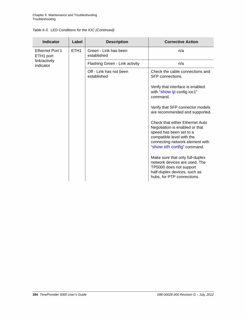
Chapter 6 Maintenance and TroubleshootingTroubleshooting
Ethernet Port 1ETH1 port link/activity indicator
ETH1 Green - Link has been established
n/a
Flashing Green - Link activity n/a
Off - Link has not been established
Check the cable connections and SFP connections.
Verify that interface is enabled. with “show ip config ioc1” command.
Verify that SFP connector models are recommended and supported.
Check that either Ethernet Auto Negotiation is enabled or that speed has been set to a compatible level with the connecting network element with “show eth config” command.
Make sure that only full-duplex network devices are used. The TP5000 does not support half-duplex devices, such as hubs, for PTP connections.
Table 6-3. LED Conditions for the IOC (Continued)
Indicator Label Description Corrective Action
394 TimeProvider 5000 User’s Guide 098-00028-000 Revision G – July, 2012

Chapter 6 Maintenance and TroubleshootingTroubleshooting
Ethernet Port 2ETH2 port link/activity indicator
ETH2 Green - Link has been established
n/a
Flashing Green - Link activity n/a
Off - Link has not been established
Check the cable connections and SFP connections.
Verify that interface is enabled. with “show ip config ioc1” command
Verify that SFP connector models are recommended and supported.
Check that either Ethernet Auto Negotiation is enabled or that speed has been set to a compatible level with the connecting network element with “show eth config” command.
Make sure that only full-duplex network devices are used. The TP5000 does not support half-duplex devices, such as hubs, for PTP connections.
Local Oscillator StateIndicates the current mode of operation of the LO servo
HOLD Off - Oscillator is operating in Locked mode
n/a
Amber - Oscillator is operating in Holdover or Acquire modes
Check the reference input source to verify that it is connected and operational.
Flashing Amber - Oscillator is operating in Warm-up mode
Typical warm-up time for the Active card is:
Quartz 30 40 minutes
Rubidium 50 60 minutes
Standby IOC starts locking to Active IOC after Active IOC enters normal track. Allow an additional ~20 minutes for Standby card to completes warm-up.
Table 6-3. LED Conditions for the IOC (Continued)
Indicator Label Description Corrective Action
098-00028-000 Revision G – July, 2012 TimeProvider 5000 User’s Guide 395

Chapter 6 Maintenance and TroubleshootingTroubleshooting
Diagnosing the IMC Reading LED Conditions
Table 6-4 shows the function of the LED indicators on the front panel of the IMC.
Table 6-4. LED Conditions for the IMC
Indicator Label Description Corrective Action
Power Indicator (IOC and IMC)
PWR Green - Module power available n/a
Off - Module power not available Check power supply
See Table 6-2 ,“No LED lit on any module” for probable causes and more corrective actions.
-48V A-BusA-Bus Battery Indicator (IMC)
BT A Off - A-Bus power OK n/a
Red - A-Bus power failed Check power level from power supply to power module A.
Check connections to primary power module A.
Check ground connections.
Check A fuse on the branch over-current protection unit, and replace if it is blown.
-48V B-BusB-Bus Battery Indicator (IMC)
BT B Off - B-Bus power OK n/a
Red - B-Bus power failed Check power level from power supply to power module B.
Check connections to primary power module B.
Check ground connections.
Check B fuse on the branch over-current protection unit, and replace if it is blown.
396 TimeProvider 5000 User’s Guide 098-00028-000 Revision G – July, 2012

Chapter 6 Maintenance and TroubleshootingTroubleshooting
System HealthAggregation of system alarms indicator
SYS Off - IMC, IOC operating normally n/a
Amber - IMC, IOC operational Minor Alarm(s)
Use “show alarm” command to view alarm IDs and descriptions.
See Table A-1 in Appendix A, System Messages for corrective actions.
Red - IMC, IOC operational Major or Critical Alarm(s)
Use “show alarm” command to view alarm IDs and descriptions.
See Table A-1 in Appendix A, System Messages for corrective actions. After taking corrective actions, use “reboot” command to reboot the card that had the major or critical alarm..
IMC AlarmIMC module alarm/fault indicator
ALM Off - IMC operating normally n/a
Flashing Green - Software starting up
Wait for IMC to finish booting.
Amber - IMC operational Minor Alarm(s)
Use “show alarm” command to view alarm IDs and descriptions.
See Table A-1 in Appendix A, System Messages for corrective actions.
Red - IMC operational Major/Critical Alarm(s)
Use “show alarm” command to view alarm IDs and descriptions.
See Table A-1 in Appendix A, System Messages for corrective actions. After taking corrective actions, use “reboot imc” command.
Table 6-4. LED Conditions for the IMC (Continued)
Indicator Label Description Corrective Action
098-00028-000 Revision G – July, 2012 TimeProvider 5000 User’s Guide 397
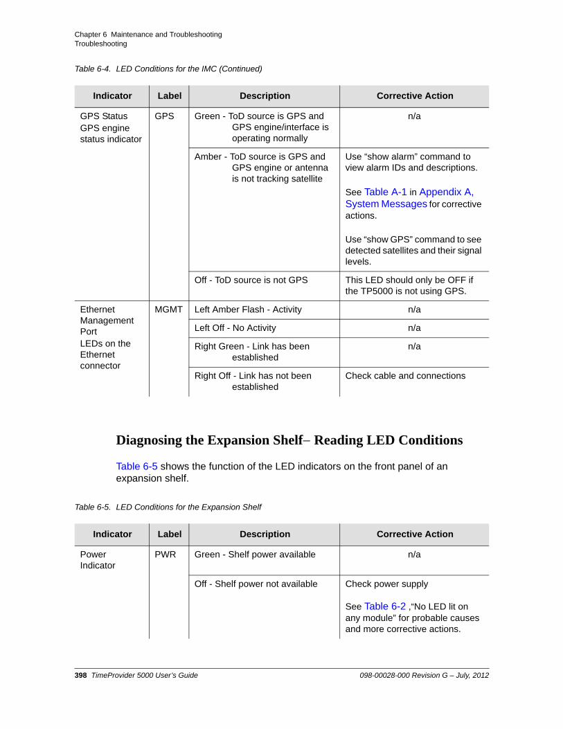
Chapter 6 Maintenance and TroubleshootingTroubleshooting
Diagnosing the Expansion Shelf Reading LED Conditions
Table 6-5 shows the function of the LED indicators on the front panel of an expansion shelf.
GPS StatusGPS engine status indicator
GPS Green - ToD source is GPS and GPS engine/interface is operating normally
n/a
Amber - ToD source is GPS and GPS engine or antenna is not tracking satellite
Use “show alarm” command to view alarm IDs and descriptions.
See Table A-1 in Appendix A, System Messages for corrective actions.
Use “show GPS” command to see detected satellites and their signal levels.
Off - ToD source is not GPS This LED should only be OFF if the TP5000 is not using GPS.
Ethernet Management PortLEDs on the Ethernet connector
MGMT Left Amber Flash - Activity n/a
Left Off - No Activity n/a
Right Green - Link has been established
n/a
Right Off - Link has not been established
Check cable and connections
Table 6-5. LED Conditions for the Expansion Shelf
Indicator Label Description Corrective Action
Power Indicator
PWR Green - Shelf power available n/a
Off - Shelf power not available Check power supply
See Table 6-2 ,“No LED lit on any module” for probable causes and more corrective actions.
Table 6-4. LED Conditions for the IMC (Continued)
Indicator Label Description Corrective Action
398 TimeProvider 5000 User’s Guide 098-00028-000 Revision G – July, 2012

Chapter 6 Maintenance and TroubleshootingTroubleshooting
-48V A-BusA-Bus Battery Indicator)
BT A Off - A-Bus power OK n/a
Red - A-Bus power failed Check power level from power supply to power module A.
Check connections to primary power module A.
Check ground connections.
Check A fuse on the branch over-current protection unit, and replace if it is blown.
-48V B-BusB-Bus Battery Indicator (IMC)
BT B Off - B-Bus power OK n/a
Red - B-Bus power failed Check power level from power supply to power module B.
Check connections to primary power module B.
Check ground connections.
Check B fuse on the branch over-current protection unit, and replace if it is blown.
Expansion Shelf alarm/fault indicator
ALM Off - Expansion shelf operating normally
n/a
Flashing Green - Software starting up
Wait for expansion shelf to finish booting.
Amber -Expansion shelf operational Minor Alarm(s)
Use “show alarm” command to view alarm IDs and descriptions.
See Table A-1 in Appendix A, System Messages for corrective actions.
Red - Expansion shelf operational Major/Critical Alarm(s)
Use “show alarm” command to view alarm IDs and descriptions.
See Table A-1 in Appendix A, System Messages for corrective actions. After taking corrective actions, use “reboot imc” command.
Table 6-5. LED Conditions for the Expansion Shelf (Continued)
Indicator Label Description Corrective Action
098-00028-000 Revision G – July, 2012 TimeProvider 5000 User’s Guide 399

Chapter 6 Maintenance and TroubleshootingRepairing the TimeProvider 5000
Repairing the TimeProvider 5000
Repairing the TimeProvider 5000 is limited to replacing modules. Refer to Working With Modules, on page 67, for information on how to properly handle modules to prevent electrostatic or physical damage.
Each power module in the TimeProvider contains a 3A fuse, but these fuses are not field-replaceable. There are no field-serviceable fuses in the TimeProvider 5000. If a fuse blows in a TimeProvider 5000, the unit must be returned to the factory for repair.
DTI/ETH Expansion shelf PortLEDs on the Ethernet connector
MGMT Green - Activity on link to TP 5000 IMC DTI/ETH expansion port
n/a
Green Flash - Link to TP 5000 IMC DTI/ETH expansion port has been established
n/a
Off - Link to TP 5000 IMC DTI/ETH expansion port has not been established
Check cable and connections
GPS StatusGPS engine status indicator
REF Green - Exp clock is in fast tracking or normal tracking
n/a
Amber - Expansion clock is in holdover or acquire mode
Use “show alarm” command to view alarm IDs and descriptions.
See Table A-1 in Appendix A, System Messages for corrective actions.
Use “show GPS” command to see detected satellites and their signal levels.
Amber Flash - Expansion clock is in warm-up
n/a
Table 6-5. LED Conditions for the Expansion Shelf (Continued)
Indicator Label Description Corrective Action
400 TimeProvider 5000 User’s Guide 098-00028-000 Revision G – July, 2012

Chapter 6 Maintenance and TroubleshootingRepairing the TimeProvider 5000
Removing the IOC
You can remove either of two IOCs in a chassis without affecting outputs. If you need to remove the only IOC in a chassis, or remove both IOCs from a chassis, outputs are interrupted and will resume once one IOC has achieved normal operating state.
Removing the Only IOC in a ChassisTo remove the only IOC in a chassis, use the following procedure. Output signals will be interrupted; they will resume once the IOC has achieved normal operating state.
1. Save the contents of the IOC memory in the IMC by issuing the following command:
Type set configuration backup ioc-to-imc and press Enter.
2. Attach a wrist grounding strap and connect it to the TimeProvider 5000 chassis.
3. Loosen the captive retaining screws and pull out on them to unseat the IOC from the chassis.
4. Place the IOC in a static-free bag or on a static-free surface.
Install a new IOC using the appropriate procedure in Replacing the IOC, on page 401.
Replacing the IOC
This section contains procedures for replacing IOC in three circumstances:
Replacing the only IOC in a chassis
Replacing one of two IOCs in a chassis
Replacing both IOCs in a chassis
Replacing the Only IOC In a ChassisTo replace the IOC in a chassis, use the following procedure. Output signals will resume once the IOC has achieved normal operating state. This procedure assumes that you have stored the contents of the IOC memory in the IMC using the Set Configuration Backup command.
Warning: To avoid possible electrostatic damage to the IOC, place it in a static-free bag or on a static-free surface.
098-00028-000 Revision G – July, 2012 TimeProvider 5000 User’s Guide 401

Chapter 6 Maintenance and TroubleshootingRepairing the TimeProvider 5000
1. Attach a wrist grounding strap and connect it to the TimeProvider 5000 chassis.
2. Remove the IOC module using the procedure above.
3. Align the new IOC module’s edges within the guides of the selected slot.
4. Slide the IOC module into the chassis and press firmly until it seats fully into its backplane edge connector.
5. Tighten the captive screws located on each side of the panel
6. Copy the contents of the IOC memory stored in the IMC by issuing the following command.
Type set configuration restore ioc and press Enter.
If you have not stored the contents of the IOC memory in the IMC, then provision the IOC using the procedures and commands described in Chapter 4, Provisioning.
4. Wait for the IOC to reboot and achieve normal operating state.
Replacing One of Two IOCs In a ChassisEnsure that the IOC card that is to be replaced is the standby card before removing it.
For this example, assume that IOC1 is the card that is to be replaced, and that it is the active card. Therefore, IOC2 is the standby card. This example demonstrates switching IOC2 to be the active card, then using the “show ioc-state” command to verify the switch.
1. Attach a wrist grounding strap and connect it to the TimeProvider 5000 chassis.
2. Type set ioc-state ioc2 active and press Enter.
3. Type show ioc-state and press Enter to verify that the standby card has been switched to active.
4. Loosen the screws and then pull out the IOC. Be sure to place the IOC on a static-free surface.
Note: Removing the active card is not recommended. Before removing the active card, manually switch the active IOC card to standby using steps 2 and 3 in the procedure below.
Note: Switchover to the standby IOC will be prohibited if the standby IOC has alarms of higher severity than the active IOC or if the standby IOC is still in warm-up. Check system status and alarms if the command fails.
402 TimeProvider 5000 User’s Guide 098-00028-000 Revision G – July, 2012

Chapter 6 Maintenance and TroubleshootingRepairing the TimeProvider 5000
5. Align the new IOC module’s edges within the guides of the selected slot.
6. Slide the IOC module into the chassis and press firmly until it seats fully into its backplane edge connector.
7. Tighten the captive screws located on each side of the panel
8. The configuration of the newly-installed IOC will be set from the active IOC in the system. Wait for the new IOC to reboot and achieve normal operating state.
9. To switch the new IOC card as the active card, type set ioc-state ioc1 active and press Enter.
10.Type show ioc-state and press Enter to verify that the standby card has been switched to active.
Replacing Both IOCs In a ChassisTo avoid interrupting outputs in a redundant system, replace the standby module first. Install the new module, then wait until it leaves warm-up before making it active. Then replace the other module.
If it does not matter whether outputs are interrupted, use the Replacing the Only IOC In a Chassis procedure above to replace each IOC module.
For this example, assume that IOC1 is the card that is to be replaced first, and that it is the active card. Therefore, IOC2 is the standby card. This example demonstrates switching IOC2 to be the active card, then using the “show ioc-state” command to verify the switch.
1. Attach a wrist grounding strap and connect it to the TimeProvider 5000 chassis.
2. Type set ioc-state ioc2 active and press Enter.
3. Type show ioc-state and press Enter to verify that the standby card has been switched to active.
4. Loosen the screws and then pull out IOC1. Be sure to place the IOC on a static-free surface.
Note: Removing the active card is not recommended. Before removing the active card, manually switch the active IOC card to standby using steps 2 and 3 in the procedure below.
Note: Switchover to the standby IOC will be prohibited if the standby IOC has alarms of higher severity than the active IOC or if the standby IOC is still in warm-up. Check system status and alarms if the command fails.
098-00028-000 Revision G – July, 2012 TimeProvider 5000 User’s Guide 403

Chapter 6 Maintenance and TroubleshootingRepairing the TimeProvider 5000
5. Align the new IOC module’s edges within the guides of the IOC1 slot.
6. Slide the IOC module into the chassis and press firmly until it seats fully into its backplane edge connector.
7. Tighten the captive screws located on each side of the panel
8. The configuration of the newly-installed IOC will be set from the active IOC in the system. Before replacing the second IOC, wait for the first IOC to reboot and leave the warm-up state.
9. To switch the first new IOC card as the active card, type set ioc-state ioc1 active and press Enter.
10.Type show ioc-state and press Enter to verify that the standby card has been switched to active.
11.Repeat steps 4 through 8 of this procedure for IOC2.
Replacing the IMC
You can remove the IMC from the chassis and replace it without affecting outputs.
1. Save the contents of the IMC memory in an IOC (example is for IOC1) by issuing the following command:
Type set configuration backup imc-to-ioc1 and press Enter.
2. Attach a wrist grounding strap and connect it to the TimeProvider 5000 chassis.
3. Remove the IMC by loosening the captive screws and pulling the IMC from the chassis.
4. Place the IMC in a static-free bag or on a static-free surface.
5. Insert another IMC into the chassis and tighten the captive screws.
6. Reload the IMC memory from the IOC by issuing the following command:
Caution: You must disconnect the GPS antenna cable before removing the IMC module.‘
Warning: To avoid possible electrostatic damage to the IMC, place it in a static-free bag or on a static-free surface.
404 TimeProvider 5000 User’s Guide 098-00028-000 Revision G – July, 2012

Chapter 6 Maintenance and TroubleshootingUpgrading the Firmware
Type set configuration restore imc-from-ioc1 and press Enter..
Upgrading the Firmware
You can upgrade the firmware in the IMC, IOC or redundant IOCs, or expansion shelves using CLI commands and software available from Symmetricom. Only users with Admin level access can execute the “upgrade” command. The command places the IMC in the firmware download mode and prevents all other sessions from making changes to the configuration. During the upgrade process, no new sessions are allowed. Refer to Chapter 3, CLI Commands and SNMP and the command upgrade, on page 255 for details on the upgrade process.
The upgrade procedure to be used to upgrade the TP 5000 is based on the configuration of the TP 5000, firmware version from which the unit is being upgraded, and whether loss of outputs is acceptable.
TP5000 with a single IOC module upgrading from 1.1.8 or 1.2.3 release to 2.x, please follow the procedure TP5000 Upgrade - Loss of Outputs below.
TP5000 with Redundant IOC modules upgrading from 1.1.8 release to 2.x, please follow the step-by-step procedure TP5000 with Redundant IOC Modules v1.1.8 - No Loss of Outputs below.
TP5000 with Redundant IOC modules upgrading from 1.2.3 release to 2.x, please follow the step-by-step procedure TP5000 with Redundant IOC Modules v1.2.3 - No Loss of Outputs below.
All systems: When upgrading from released versions prior to 1.1.8, the upgrade process must be performed in two steps. The TP5000 must be upgraded to 1.1.8 first and then upgraded to 2.x using the relevant procedure below. See page 258 in Rev. D of the TimeProvider User’s Guide (098-00028-000 Rev. D) for the procedure “Upgrading from TP5000 v1.0 to v1.1 or Higher”.
Upon receipt of any new/repaired equipment, perform the relevant software upgrade procedure below prior to putting the shelf into service.
Warning: To avoid possible electrostatic damage to the module or panel, place it in a static-free bag or on a static-free surface.
098-00028-000 Revision G – July, 2012 TimeProvider 5000 User’s Guide 405

Chapter 6 Maintenance and TroubleshootingUpgrading the Firmware
Note: If a PTP probe license is installed, follow the procedure TP5000 Upgrade - Loss of Outputs. The system will enable PTP probe mode (default) when different firmware versions are operating within the system. This will occur during the system upgrade of a TP5000 with redundant IOC modules, and the system must be returned to the grandmaster mode to restore outputs. Use the commands "set packet-service ioc1-1 ptp-gm" and "set packet-service ioc1-2 ptp-gm" to return to grandmaster mode.
Caution: To avoid a possible service call, do not issue a command to the TimeProvider 5000, do not remove power from the TimeProvider 5000, and do not remove an IOC or IMC from the chassis during the upgrade process. Doing so could corrupt the flash memory in a module, disabling the TimeProvider 5000.
Note: Linux, Windows, and other third-party FTP servers can be used in the upgrade process of the TP5000.
Note: If you need assistance selecting an SFTP server application, contact Symmetricom Global Services. See Contacting Technical Support, on page 421.
406 TimeProvider 5000 User’s Guide 098-00028-000 Revision G – July, 2012

Chapter 6 Maintenance and TroubleshootingUpgrading the Firmware
TP5000 Upgrade - Loss of Outputs
This method is the easiest and quickest upgrade method, but there will be Loss of Service (LOS) at reboot. The IMC and IOC must be rebooted together after all components are upgraded.
1. Verify that SSH or telnet connection to IMC is available
2. Upgrade IMC to 2.x using the command "upgrade imc <filepath> [ftp: | sftp:] <ftp-ip-address> <username>", but DO NOT reboot
3. Upgrade IOC1 to 2.x, and if present, IOC2. Use the command "upgrade iocx <filepath> [ftp: | sftp:] <ftp-ip-address> <username>" (where x is either 1 or 2), but DO NOT reboot
4. Reboot system with "reboot system" CLI command
5. Verify that the TimeProvider 5000 is running correctly by issuing commands "show status", "show alarm", and "show inventory". If the system is showing an alarm for a setting that is disabled, re-enable and disable that setting and the alarm will be cleared.
Note: The FTP firewall is set to “Block” by default. Use the following command to set the IMC firewall to “Allow” for telnet communications:
set firewall imc ftp allow
Note: The TimeProvider 5000 only supports active FTP; it does not support passive (PASV) mode.
Note: For SFTP, both the SFTP and SSH firewalls must be set to “Allow”. They are both set to “Allow” by default.
Note: If an SFTP server is used, the protocol does not need to be included with the address.
ftp:192.168.5.64[sftp:]192.168.5.64
098-00028-000 Revision G – July, 2012 TimeProvider 5000 User’s Guide 407

Chapter 6 Maintenance and TroubleshootingUpgrading the Firmware
TP5000 with Redundant IOC Modules v1.2.3 - No Loss of Outputs
This approach should be used to avoid LOS for a TP5000 with redundant IOC modules. It is critical that the IMC is rebooted immediately after the IOC. Since there are two IOCs present within the shelf, the IMC will be rebooted twice.
1. Verify that SSH or telnet connection to IMC is available. Verify that a PTP probe option is not installed. This requires using both the "show license" and "show option" CLI commands. If there is a probe license, you must follow the procedure TP5000 Upgrade - Loss of Outputs.
2. Verify that both IOC outputs on the active card are functioning properly by checking the active alarms with the "show alarm" CLI command. If any alarms are present, resolve these issues first before proceeding.
3. Upgrade IMC to 2.x using the command "upgrade imc <filepath> [ftp: | sftp:] <ftp-ip-address> <username>", but DO NOT reboot
4. Upgrade both IOCs to 2.x using the command "upgrade iocx <filepath> [ftp: | sftp:] <ftp-ip-address> <username>" (where x is either 1 or 2), but DO NOT reboot
5. Once all modules have been loaded with the correct 2.x revision, issue the "show status" command, taking note as to which IOC module is standby and which is active.
Note: The FTP firewall is set to “Block” by default. Use the following command to set the IMC firewall to “Allow” for telnet communications:
set firewall imc ftp allow
Note: The TimeProvider 5000 only supports active FTP; it does not support passive (PASV) mode.
Note: For SFTP, both the SFTP and SSH firewalls must be set to “Allow”. They are both set to “Allow” by default.
Note: If an SFTP server is used, the protocol does not need to be included with the address.
ftp:192.168.5.64[sftp:]192.168.5.64
408 TimeProvider 5000 User’s Guide 098-00028-000 Revision G – July, 2012

Chapter 6 Maintenance and TroubleshootingUpgrading the Firmware
6. Reboot the standby IOC module by issuing the command "reboot iocx" (where the x is the standby IOC position, either 1 or 2). Immediately after the Tp5000> prompt returns from this command, issue the command "reboot imc".
7. Allow both the standby IOC and the IMC to fully reboot and then log into the TimeProvider 5000.
8. Issue the command "show status". The current reference input and the phase offset fields may be incorrect - this is temporary. Please ignore this.
Issue the command "show alarm". At this point in the upgrade procedure there may be alarms present that are invalid- this is temporary. Please ignore this. Wait until the standby IOC changes from standby warm-up mode to standby.
9. Make standby IOC active with the command "set ioc-state iocx active" (where x is the standby IOC, either 1 or 2).
10.Verify IOC switch state with "show ioc-state" CLI command. Also verify that the current standby IOC is running the previous firmware version with "show inventory".
11.Reboot standby IOC with "reboot iocx" (where the x is the standby IOC position, either 1 or 2). Immediately after the prompt returns, reboot IMC with "reboot imc".
12.After the standby IOC module and IMC module return to service, log into the TimeProvider 5000 and issue the command "show inventory". Make sure all of the modules are now at the desired 2.x revision.
13.Issue the command "show ref". All of the input references that are not being used must be disabled. Choose the appropriate commands from the list below for the input references that need to be disabled:
set gnss state disableset gps state disableset input state port1 disableset input state port2 disableset pps-tod state port1 disableset pps-tod state port2 disable
14.Verify that the TimeProvider 5000 is running correctly by issuing commands "show status", "show alarm", and "show inventory".
098-00028-000 Revision G – July, 2012 TimeProvider 5000 User’s Guide 409

Chapter 6 Maintenance and TroubleshootingUpgrading the Firmware
TP5000 with Redundant IOC Modules v1.1.8 - No Loss of Outputs
This approach should be used to avoid LOS with a TP5000 with redundant IOC modules. It is critical that the IMC is rebooted immediately after the IOC. Since there are two IOCs present within the shelf, the IMC will be rebooted twice.
1. Verify that SSH or telnet connection to IMC is available.
2. Verify that both IOC outputs on the active card are functioning properly by checking the active alarms with the "show alarm" CLI command. If any alarms are present, resolve these issues first before proceeding.
3. Upgrade IMC to 2.x using the command "upgrade imc <filepath> [ftp: | sftp:] <ftp-ip-address> <username>", but DO NOT reboot
4. Upgrade both IOCs to 2.x using the command "upgrade iocx <filepath> [ftp: | sftp:] <ftp-ip-address> <username>" (where x is either 1 or 2), but DO NOT reboot
5. Once all modules have been loaded with the correct 2.x revision, issue the "show status" command, taking note as to which IOC module is standby and which is active.
6. Reboot the standby IOC module by issuing the command "reboot iocx" (where the x is the standby IOC position, either 1 or 2). Immediately after the Tp5000> prompt returns from this command issue the command "reboot imc".
Note: The FTP firewall is set to “Block” by default. Use the following command to set the IMC firewall to “Allow” for telnet communications:
set firewall imc ftp allow
Note: The TimeProvider 5000 only supports active FTP; it does not support passive (PASV) mode.
Note: For SFTP, both the SFTP and SSH firewalls must be set to “Allow”. They are both set to “Allow” by default.
Note: If an SFTP server is used, the protocol does not need to be included with the address.
ftp:192.168.5.64[sftp:]192.168.5.64
410 TimeProvider 5000 User’s Guide 098-00028-000 Revision G – July, 2012

Chapter 6 Maintenance and TroubleshootingUpgrading the Firmware
Allow both the standby IOC and the IMC to fully reboot and return to service. Once you are able to log back into the TimeProvider 5000, issue the command "show status". The current reference input and the phase offset fields may be incorrect - this is temporary. Please ignore this.
Issue the command "show alarm". At this point in the upgrade procedure, there may be alarms present that are invalid- this is temporary. Please ignore this. Wait until the standby IOC changes from standby warm-up to standby.
7. Make standby IOC active with the command "set ioc-state iocx active" (where x is the current standby IOC, either 1 or 2).
8. There will be a temporary gap in the PTP flow. To minimize the gap, immediately restart IP interfaces on IOC:
a. Use the command "set ip ioc1-1 restart" b. Use the command "set ip ioc1-2 restart"
9. Verify IOC switch state with the command "show ioc-state". Also verify that the current standby IOC is running the previous firmware version with "show inventory".
10.Reboot standby IOC with "reboot iocx" (where the x is the standby IOC position, either 1 or 2). Immediately after the prompt returns, reboot IMC with "reboot imc".
11.After the standby IOC module and IMC module return to service, log into the TimeProvider 5000 and issue the command "show inventory". Make sure all of the modules are now at the desired 2.x revision.
12.Issue the command "show ref". All of the input references that are not being used must be disabled. Choose the appropriate commands from the list below for the input references that need to be disabled:
set gnss state disableset gps state disableset input state port1 disableset input state port2 disableset pps-tod state port1 disableset pps-tod state port2 disable
13.Verify that the TimeProvider 5000 is running correctly by issuing commands "show status", "show alarm", and "show inventory".
098-00028-000 Revision G – July, 2012 TimeProvider 5000 User’s Guide 411

Chapter 6 Maintenance and TroubleshootingUpgrading the Firmware
Upgrading an Expansion Shelf
To upgrade the software in an expansion shelf with ID=4, for example, use the following procedure:
1. Login at the Admin level (see Logging In And Out, on page 376).
2. Type set configuration backup exp4-to-imc and press Enter to save the contents of the expansion shelf configuration to the IMC card.
3. Type upgrade exp{0-9] <filepath> <ftp-server> <user name> (use the IP address of the FTP server) and press Enter.
Example - FTP: For a TP E10 PTP/SyncE expansion shelf with ID=4, FTP server with IP address 192.168.5.64, a user name of “user1”, and an upgrade path of “/ver2.bin” the command is:
upgrade exp4 /ver2.bin ftp:192.168.5.64 user1
Example - SFTP: For a TP E30 E1/1PPS+TOD expansion shelf with ID=4, an SFTP server with IP address 192.168.5.65, a user name of “user1”, and a upgrade file path of “/ver2.bin” the command is:
upgrade exp4 /ver2.bin 192.168.5.65 user1
Note: The FTP firewall is set to “Block” by default. Use the following command to set the IMC firewall to “Allow” for telnet communications:
set firewall imc ftp allow
Note: The TimeProvider 5000 only supports active FTP; it does not support passive (PASV) mode.
Note: For SFTP, both the SFTP and SSH firewalls must be set to “Allow”. They are both set to “Allow” by default.
Note: If an SFTP server is used, the protocol does not need to be included with the address.
ftp:192.168.5.64[sftp:]192.168.5.64
412 TimeProvider 5000 User’s Guide 098-00028-000 Revision G – July, 2012

Chapter 6 Maintenance and TroubleshootingDowngrading the Firmware
4. When prompted, enter the password for the server. The new software is loaded into the expansion shelf with the specified ID.
5. The TimeProvider 5000 validates the received file, and if the file is valid it updates the flash memory in the expansion shelf.
Downgrading the Firmware
You can also downgrade the firmware in the IMC, IOC or redundant IOCs, or expansion shelves to an earlier version using “upgrade” and other CLI commands and software available from Symmetricom. Only users with Admin level access can execute the “upgrade” command.
This section describes the downgrade procedure. There will be loss of outputs at reboot and the configuration must be set to factory defaults.
1. Verify that SSH or telnet connection to IMC is available
2. Downgrade IMC using the command "upgrade imc <filepath> [ftp: | sftp:] <ftp-ip-address> <username>", but DO NOT reboot
Note: The system will transfer the file from the specified server and then upgrade the expansion shelf.
Note: If the file is not valid, the TimeProvider 5000 will reject it.
Note: To avoid incompatibility issues, you must use configuration files created with the firmware release version to which the unit has been downgraded. Symmetricom does not recommend downgrading a system which is in service.
Note: Check the hardware compatibility matrix in Table 6-6 before downgrading.
Note: The FTP firewall is set to “Block” by default. Use the following command to set the IMC firewall to “Allow” for telnet communications:
set firewall imc ftp allow
098-00028-000 Revision G – July, 2012 TimeProvider 5000 User’s Guide 413

Chapter 6 Maintenance and TroubleshootingTimeProvider 5000 Part Numbers
3. Downgrade IOC1 and if present, IOC2. Use the command "upgrade iocx <filepath> [ftp: | sftp:] <ftp-ip-address> <username>" (where x is either 1 or 2), but DO NOT reboot
4. Reboot system with "reboot system" CLI command
5. Set factory defaults with “set configuration factory” CLI command
6. Verify that the TimeProvider 5000 is running correctly by issuing commands "show status", "show alarm", and "show inventory". If the system is showing an alarm for a setting that is disabled, re-enable and disable that setting and the alarm will be cleared.
TimeProvider 5000 Part Numbers
The TimeProvider 5000 can operate in either a basic configuration, or in a redundant configuration in one chassis. Basic configuration consists of the following components:
1 Chassis
1 IMC module
1 IOC module
Redundant configuration consists of the following components:
1 Chassis
Note: The TimeProvider 5000 only supports active FTP; it does not support passive (PASV) mode.
Note: For SFTP, both the SFTP and SSH firewalls must be set to “Allow”. They are both set to “Allow” by default.
Note: If an SFTP server is used, the protocol does not need to be included with the address.
ftp:192.168.5.64[sftp:]192.168.5.64
Note: When operating in basic configuration, blank panels are available to cover the vacant module slots in the chassis.
414 TimeProvider 5000 User’s Guide 098-00028-000 Revision G – July, 2012

Chapter 6 Maintenance and TroubleshootingTimeProvider 5000 Part Numbers
1 IMC module
2 IOC modules
See System and Accessory Part Numbers, on page 416.
See Table 6-6 for the minimum firmware revisions required for TP 5000 hardware.
Compatibility Matrix
Table 6-6 below describes the minimum firmware revision required for TP 5000 hardware. The IMC, IOC and expansion shelves must contain the same firmware revision (see Upgrading the Firmware, on page 405)..
Table 6-6. Compatibility Matrix - TP5000 Hardware and Firmware
Description P/N HW Rev.Minimum FW Rev.
Notes
IMC Module 090-50331-01 Rev L or higher 1.2.3 This module can’t distinguish between 090-50301-01 and 090-50301-02 chassis.
Rev K or lower 1.0.6 This module can’t distinguish between 090-50301-01 and 090-50301-02 chassis.
090-50331-02 2.0.4*
090-50331-04 2.0.4*
090-50331-05 2.0.4*
IMC Module - NTP 090-50332-01 2.0.4* This module can’t distinguish between 090-50301-01 and 090-50301-02 chassis.
I/O Module 090-50311-01 1.0.6**
090-50312-01 1.0.6**
090-50314-01 1.2.3**
090-50315-01 2.0.4*, ** Should be used w/ 090-50301-02 chassis
IOC Module, Quartz 090-50321-01 Rev L or higher 1.2.3
Rev K or lower 1.0.6
IOC Module, Rubidium 090-50322-01 Rev M or higher 1.2.3
Rev L or lower 1.0.6
098-00028-000 Revision G – July, 2012 TimeProvider 5000 User’s Guide 415

Chapter 6 Maintenance and TroubleshootingTimeProvider 5000 Part Numbers
* These items are also supported by firmware release 1.3.8 for China region. ** The FW revision for the I/O module refers to the IMC/IOC firmware revision.
System and Accessory Part Numbers
This section provides part numbers and descriptions for the system and accessories available for the TimeProvider 5000. Also available as separately ordered items are 23-inch (58.42 cm) rack mounting adapters and 21-inch (ETSI) rack mounting adapters. See Table 6-7 for component part numbers and Table 6-8 for connection accessories.
Main Chassis 990-50301-01 1.0.6
Main Chassis 990-50301-02 2.0.4* Chassis can be used by older firmware, but p/n can't be identified by "show inventory"
TimeProvider E10 Expansion ShelfSyncE/Ethernet
990-50401-01 2.0.4* Must be used w/ 090-50331-02, 090-50331-04, 090-50331-05
TimeProvider E30 Expansion ShelfE1 & PPS-TOD
990-50401-02 2.0.4* Must be used with 090-50331-02, 090-50331-04, 090-50331-05
Table 6-7. Component Part Numbers
Item Part Number
Base Units
TimeProvider 5000 Front Access ETSI Chassisincludes User’s Documentation CD and Installation Kit
990-50301-01
Spare TimeProvider 5000 Front Access ETSI Chassis 090-50301-01
I/O Modules
I/O Module with 4x E1 Ports and 2x UTI Ports 090-50311-01
I/O Module with 2x E1 Ports, 1PPS/10MHz Ports and 2x UTI Ports
090-50312-01
Table 6-6. Compatibility Matrix - TP5000 Hardware and Firmware
Description P/N HW Rev.Minimum FW Rev.
Notes
416 TimeProvider 5000 User’s Guide 098-00028-000 Revision G – July, 2012

Chapter 6 Maintenance and TroubleshootingTimeProvider 5000 Part Numbers
I/O Module with 2x T1 Ports, 1PPS/10MHz Ports and 2x UTI Ports
090-50314-01
I/O Module with 2x DTI expansion ports, 2x 1PPS+TOD Ports, 2x E1 ports
090-50315-01
Blank I/O Face Plate 090-50312-99
IOC and IMC Modules
Quartz IOC Module 090-50321-01
Rubidium IOC Module 090-50322-01
Blank IOC Module Face Plate 090-50322-99
IMC Card w/ Integrated GPS 090-50331-01
IMC Card w/ Integrated GPS & expansion control 090-50331-02
IMC Card w/ Integrated GPS & GNSS (GPS/Beidou) & expansion control
090-50331-04
IMC Card w/ Integrated GPS & GNSS (GPS only) & expansion control
090-50331-05
NTP IMC Module with Integrated GPS 090-50332-01
Expansion Shelves
TimeProvider E10 Ethernet expansion shelf with user documentation and installation hardware
990-50401-01
TimeProvider E30 E1/1PPS+TOD expansion shelf with user documentation and installation hardware
990-50401-02
Air filter replacement kit for TimeProvider E10 PTP/SyncE expansion shelf
093-01206-000
Installation and Rack Mounting Adaptor Kits
Hardware Installation Kit (included in 990-50301-01) 093-00050-000
21-inch (ETSI) Bracket Rack Mounting Adaptor Kit 093-00011-000
23-inch (58.42 cm) Bracket Rack Mounting Adaptor Kit 093-00012-000
Software Licenses
SNMP License 920-50370-01
TP5000 NTP w/20,000 TPS Capacity for PTP IMC 920-50370-05
TP5000 R1.2 Multicast & 2-step clock 920-50380-01
TP5000 R2.0 500 VLAN (16 base + extended 484) 920-50380-02
Table 6-7. Component Part Numbers (Continued)
Item Part Number
098-00028-000 Revision G – July, 2012 TimeProvider 5000 User’s Guide 417

Chapter 6 Maintenance and TroubleshootingTimeProvider 5000 Part Numbers
GPS Antenna
Table 6-9 lists the GPS antenna kits. Table 6-7 lists the cables available for the GPS antenna.
TP5000 PTP Probe 920-50375-01
TP5000 NTP w/120,000 TPS capacity for NTP IMC 920-50370-02
TPE10 PTP/SyncE 16 ports license(Adds availability of Ports 9-16 to standard 8 ports)
920-50470-01
Note: A blank face plate is required for EMC compliance if a slot is empty
Table 6-8. Connection Accessories
Item Part Number
Optical 1000 Base-LX Single-Mode Ethernet 1310nm SFP Transceiver
121-20621-10-2
Optical 1000 Base-SX Multi-Mode Ethernet 850nm SFP Transceiver
121-20621-11-2
RJ45 100/1000 Base-T Full-Duplex SFP Transceiver 121-20621-12-2
Mini-BNC-to-BNC Adaptor Cable Kit (4 cables) 093-00068-000
Table 6-9. GPS Antenna Kits
Part Number Description
990-13091-006 Antenna Kit, 6 Meter (3 meter and 3 meter cables), 26dB Antenna
990-13091-013 Antenna Kit, 13 Meter (3 meter and 10 meter cables), 26dB Antenna
Table 6-7. Component Part Numbers (Continued)
Item Part Number
418 TimeProvider 5000 User’s Guide 098-00028-000 Revision G – July, 2012

Chapter 6 Maintenance and TroubleshootingReturning the TimeProvider 5000
.
Returning the TimeProvider 5000
You should return the equipment to Symmetricom only after you have exhausted the troubleshooting procedures described earlier in this chapter, or if Symmetricom Global Services has advised you to return the unit.
990-13073-070 Antenna Kit, 70 Meter (10 meter and 60 meter cables), 40dB Antenna
990-13074-150 Antenna Kit, 150 Meter (10 meter and 140 meter cables), 48db Antenna
990-13075-230 Antenna Kit, 230 Meter (10 meter and 220 meter cables), 48dB Antenna/20dB Amp
Table 6-10. GPS Roof Mount Cables (spares and replacements only)
Part Number Description
58521A-001 1 Meter, LMR400 Interconnect Cable, connectorized
58521A-002 2 Meter, LMR400 Interconnect Cable, connectorized
58521A-005 5 Meter, LMR400 Interconnect Cable, connectorized
58521A-010 10 Meter, LMR400 Interconnect Cable, connectorized
58521A-015 15 Meter, LMR400 Interconnect Cable, connectorized
58521A-030 30 Meter, LMR400 Interconnect Cable, connectorized
58521A-060 60 Meter, LMR400 Interconnect Cable, connectorized
58521A-110 110 Meter, LMR400 Interconnect Cable, connectorized
58521A-220 220 Meter, LMR400 Interconnect Cable, connectorized
Note: Please retain the original packaging for re-shipping the product. If the original packaging is not available, contact Symmetricom Global Services (SGS) for assistance.
Table 6-9. GPS Antenna Kits
Part Number Description
098-00028-000 Revision G – July, 2012 TimeProvider 5000 User’s Guide 419

Chapter 6 Maintenance and TroubleshootingUser’s Guide Updates
Repacking the Unit
Return all units in the original packaging. If the original packaging is not available, contact Symmetricom Global Services. Use standard packing procedures for products being returned for repair to protect the equipment during shipment. Connectors should be protected with connector covers or the equipment should be wrapped in plastic before packaging. Ensure that the display and connectivity panels are protected when packaged.
Equipment Return Procedure
To return equipment to Symmetricom for repair:
1. Call Symmetricom Global Services (SGS) at 888-367-7966 (toll-free in USA only), 408-428-7907, or +49 700 3288 6435 in Europe, Middle East, or Africa to obtain a return material authorization number (RMA) before returning the product for service.
You can request an RMA on the internet atwww.symmetricom.com/Support/req_repair.htm.
Retain the assigned RMA number for future reference.
2. Provide a description of the problem, product item number, serial number, and warranty expiration date.
3. Provide the return shipping information (customer field contact, address, telephone number, and so forth.)
4. Ship the product to Symmetricom, transportation prepaid and insured, with the Return Material Authorization (RMA) number and item numbers or part numbers clearly marked on the outside of the container to the address given with the RMA.
Repaired equipment is returned to you with shipping costs prepaid by Symmetricom.
User’s Guide Updates
When this manual is updated the updated version will be available for downloading from Symmetricom’s internet web site. Manuals are provided in PDF format for ease of use. After downloading, you can view the manual on a computer or print it using Adobe Acrobat Reader.
Manual updates are available at:
www.symmetricom.com
420 TimeProvider 5000 User’s Guide 098-00028-000 Revision G – July, 2012

Chapter 6 Maintenance and TroubleshootingContacting Technical Support
Contacting Technical Support
To order any accessory, contact the Symmetricom Sales Department. See http://www.symmetricom.com/company/contact-information/sales-offices for sales support contact information.
If you encounter any difficulties installing or using the product, contact Symmetricom Global Services:
USA and CanadaSymmetricom, Inc. 2300 Orchard Parkway San Jose, CA 95131-1017
Toll-free in North America: 1-888-367-7966 Telephone: 408-428-7907 Fax: 408-428-7998email: [email protected]: www.symmetricom.com
Europe, Middle East, and Africa (EMEA)Symmetricom Global Services EMEAAltlaufstrasse 4285635 Hoehenkirchen-Siegertsbrunn Germany Telephone: +49 700 3288 6435Fax: +49 8102 8961 533E-mail: [email protected]
Note: If you are downloading a product manual for the first time, you will need to register with Symmetricom for a username and password. If you are currently registered, login and download the manual update.
098-00028-000 Revision G – July, 2012 TimeProvider 5000 User’s Guide 421

Chapter 6 Maintenance and TroubleshootingContacting Technical Support
422 TimeProvider 5000 User’s Guide 098-00028-000 Revision G – July, 2012

Appendix A System Messages
This section provides information about the system messages that are displayed in response to a provisioning event or to an alarm that occurs when an associated threshold or timer is outside of the provisioned setting. These system messages apply to the TimeProvider 5000, as well as the TimeProvider E10 and TimeProvider E30 expansion shelves.
In This Appendix
Message provisioning
System Notification Messages
098-00028-000 Revision G – July, 2012 TimeProvider 5000 User’s Guide 423

Appendix A System MessagesMessage provisioning
Message provisioning
The TimeProvider 5000 and its expansion shelves support logging of events using syslog defined facility and severity codes and system defined facility codes as follows:
Facility codes
4 Security/authorization messages
20 Time Provider 5000 Messages (events and alarms)
21 TimeProvider 5000 Command History
22 TimeProvider 500 Messages (events and alarms)
Severity codes
2 (critical) Critical: critical conditions
3 (major) Error: error conditions
4 (minor) Warning: warning conditions
5 (event) Notice: normal but significant condition
The syslog message format is as follows:
Mmm dd hh:mm:ss host_name Process-name AlarmID,Index,Severity, MsgText
Where:
Mmm = Month; dd = date; hh:mm:ss = system time
Notes:
1. Severity codes 2, 3, and 4, are also indicated by the Alarm LED(s) on the IMC and IOC modules.
2. Severity Code 2 indicate Critical Alarms.
3. Severity Code 3 indicates Major Alarms.
4. Severity Code 4 indicates Minor Alarms.
5. Severity Code 5 indicates Events and does not affect the Alarm LED.
424 TimeProvider 5000 User’s Guide 098-00028-000 Revision G – July, 2012
Appendix A System MessagesSystem Notification Messages
host_name = hostname
process-name = alarmd
AlarmID = 000 thru Max_AlarmID
Index = 0 thru 63
Severity = Event | Minor | Major | Critical (defined by severity code)
MsgText = (see tables)
The following is an example syslog message showing Input Port 1 loss of signal:
Aug 19 21:23:12 TP5000 alarmd: 035,003,Minor, IOC1: Input Port-1 Loss of Signal
Syslog messages are stored according to facility code and/or severity:
Syslog messages with facility code 4 are stored in the Security Log.
Syslog messages with facility code 20 and a severity of 2 | 3 | 4 are stored in the Alarm Log.
Syslog messages with facility code 20 and a severity of 5 are stored in the Event Log.
Syslog messages with facility code 21 are stored in the Command Log.
Syslog messages with facility code 22 are not stored in the TP5000. They can be forwarded to the remote syslog server.
System Notification Messages
Table A-1 provides a list of system notification messages. These messages are logged and sent to a remote syslog server if configured. Alarms will also generate an SNMP trap.
098-00028-000 Revision G – July, 2012 TimeProvider 5000 User’s Guide 425

Appendix A System MessagesSystem Notification Messages
Table A-1. System Notification Messages
DescriptionComp
IDEvent
IDMsgLevel
Trans-itory
MsgText Corrective Action
Communication to peer card failed
(See Table A-2 for Secondary Index Info)
IMCIOC
0 Critical No Communication to <card> failed
Communication to <card> failure cleared
Troubleshoot any existing system alarms
None required
GNSS/GPS receiver communications failed
(See Table A-2 for Secondary Index Info)
IMC 1 Minor No GNSS/GPS receiver communications failed
GNSS/GPS receiver communications failure cleared
Check for any system alarms and rectify as needed
None required
GNSS/GPS receiver not tracking satellite
(See Table A-2 for Secondary Index Info)
IMC 2 Minor No GNSS/GPS receiver not tracking satellite
GNSS/GPS receiver not tracking satellite cleared
Check antenna and connections
None required
System time invalid
(See Table A-2 for Secondary Index Info)
IMC 3 Major No System time <source> invalid
System time <source> invalid cleared
Troubleshoot TOD source
None required
System time has been set by reference
(See Table A-2 for Secondary Index Info)
IMC 4 Event Yes System time has been set by reference <source>
None required
System log time has been updated
IMC 5 Event Yes System log time has been updated
None required
Management port link down
IMC 6 Minor No Management port link down
Management port link down cleared
Check network connections
None required
426 TimeProvider 5000 User’s Guide 098-00028-000 Revision G – July, 2012

Appendix A System MessagesSystem Notification Messages
Ethernet port (ETH1 or ETH2) link down
(See Table A-2 for Secondary Index Info)
IOC1IOC2EXPxx = 09
7 Minor No <port> Ethernet port link down
<port> PTP Ethernet port link down cleared
Check network connections
None required
Manual sync IOC time to IMC required
IMC 8 Minor No Manual sync IOC time to IMC required
Manual sync IOC time to IMC not required
Sync IOC time to clear alarm with “sync tod-source now” command
None required
Power out of range
(See Table A-2 for Secondary Index Info)
IMCEXPxx = 09
9 Critical No <x.x V> power out of range (voltage value)
<x.x V> power out of range cleared (voltage value)
Hardware failure - Replace module
None required
GNSS/GPS antenna voltage out of range
IMC 10 Major No GNSS/GPS antenna voltage out of range (voltage value)
GNSS/GPS antenna voltage out of range cleared (voltage value)
Check antenna connections
None required
GNSS/GPS antenna current out of range
IMC 11 Major No GNSS/GPS antenna current out of range (current value)
GNSS/GPS antenna current within range (current value)
Check all cable and antenna connections, check voltage suppressor
None required
GNSS/GPS antenna short-circuit
(See Table A-2 for Secondary Index Info)
IMC 12 Minor No GNSS/GPS antenna short-circuit (voltage value)
GNSS/GPS antenna short-circuit cleared (voltage value)
Check all cable and antenna connections, check voltage suppressor
None required
Table A-1. System Notification Messages (Continued)
DescriptionComp
IDEvent
IDMsgLevel
Trans-itory
MsgText Corrective Action
098-00028-000 Revision G – July, 2012 TimeProvider 5000 User’s Guide 427

Appendix A System MessagesSystem Notification Messages
GNSS/GPS antenna open-circuit
(See Table A-2 for Secondary Index Info)
IMC 13 Minor No GNSS/GPS antenna open-circuit
GNSS/GPS antenna open- circuit cleared
Check all cable and antenna connections, check voltage suppressor
None required
Battery(-48V)-A failure
IMCEXPxx = 09
14 Major No Battery (-48V) -A failure
Battery (-48V) -A failure cleared
Troubleshoot the -48V power supply. Check voltage supply to A side of shelf
None required
Battery(-48V)-B failure
IMCEXPxx = 09
15 Major No Battery (-48V) -B failure
Battery (-48V) -B failure cleared
Troubleshoot the -48V power supply. Check voltage supply to B side of shelf
None required
FPGA access failure
IMCIOC1IOC2EXPxx = 09
16 Critical No FPGA access failure
FPGA access failure cleared
Hardware fault -Replace module
None required
Flash partition failure
(See Table A-2 for Secondary Index Info)
IMCIOC1IOC2EXPxx = 09
17 Critical No Flash partition failure
Flash partition failure cleared
Hardware fault -Replace module
None required
Phase-lock-loop (PLL) unlock error
IMC 18 Critical No PLL unlock error
PLL unlock error cleared
Reboot System - If alarm remains, replace module
None required
Table A-1. System Notification Messages (Continued)
DescriptionComp
IDEvent
IDMsgLevel
Trans-itory
MsgText Corrective Action
428 TimeProvider 5000 User’s Guide 098-00028-000 Revision G – July, 2012

Appendix A System MessagesSystem Notification Messages
Internal communication error
(See Table A-2 for Secondary Index Info)
IOC 19 Critical No Internal communication error
Internal communication error cleared
Reboot System - If alarm remains, replace module
None required
FPGA temperature exceed limit
IOC1IOC2EXPxx = 09
20 Minor No FPGA temperature exceed limit
FPGA temperature exceed limit cleared
Check room temperature setting.
None required
IOC detected but none of them active
IMC 21 Major No IOC detected but none of them active
Active IOC detected
Reboot system
None required
Module reboot IMCIOC1IOC2EXPxx = 09
22 Event Yes Module reboot None required
Real Time Engine (RTE) communication to peer error
IOC 23 Major No RTE communication to peer error
RTE communication to peer error cleared
Reboot System - If alarm remains, replace IOC module
None required
Entered warmup mode
IOC1IOC2EXPxx = 09
24 Minor No Entered warmup mode
Transitioned out of warmup mode
None required - If still present after 30 min. check other system alarms
None required
Entered freerun mode
IOC1IOC2EXPxx = 09
25 Event No Entered freerun mode
Transitioned out of freerun mode
If freerun mode not desired, check system input reference
None required
Table A-1. System Notification Messages (Continued)
DescriptionComp
IDEvent
IDMsgLevel
Trans-itory
MsgText Corrective Action
098-00028-000 Revision G – July, 2012 TimeProvider 5000 User’s Guide 429

Appendix A System MessagesSystem Notification Messages
Entered fast-track mode
IOC1IOC2EXPxx = 09
26 Event No Entered fast-track mode
Transitioned out of fast-track mode
None required
None required
Entered normal-track mode
IOC1IOC2EXPxx = 09
27 Event No Entered normal-track mode
Transitioned out of normal-track mode
None required
None required
Entered bridging mode
IOC1IOC2EXPxx = 09
28 Event No Entered bridging mode
Transitioned out of bridging mode
Check input system reference
None required
Entered holdover mode
IOC1IOC2EXPxx = 09
29 Minor No Entered holdover mode
Transitioned out of holdover mode
Check input system reference
None required
In holdover mode for extended period
IOC 30 Major No In holdover mode for extended period
Transitioned out of extended holdover mode
Check input system reference
None required
Operational failure
(See Table A-2 for Secondary Index Info)
IMCIOC
31 Critical No Operational failure
Operational failure cleared
Check system alarms- troubleshoot as required to determine recommended action
None required
Input active
(See Table A-2 for Secondary Index Info)
IMCIOC
32 Event No <input> active
<input>inactive
None required
Check state of input port
Table A-1. System Notification Messages (Continued)
DescriptionComp
IDEvent
IDMsgLevel
Trans-itory
MsgText Corrective Action
430 TimeProvider 5000 User’s Guide 098-00028-000 Revision G – July, 2012

Appendix A System MessagesSystem Notification Messages
IOC-to-IOC sync fault
IOC 33 Major No IOC-to-IOC sync fault
IOC-to-IOC sync fault cleared
Hardware fault -Replace module
None required
Input disqualified as system reference
(See Table A-2 for Secondary Index Info)
IOC 34 Minor No <input> disqualified as system reference
<input> disqualification cleared
Check system input reference
None required
Input loss of signal
(See Table A-2 for Secondary Index Info)
IOC 35 Minor No <input> loss of signal
<input> loss of signal cleared
Check system input reference
None required
Input phase error
(See Table A-2 for Secondary Index Info)
IMCIOC
36 Minor No <input> phase error
<input> phase error cleared
Check system input reference
None required
Internal phase-lock-loop (IPLL) to Input not settled
(See Table A-2 for Secondary Index Info)
IMCIOC
37 Minor No <input> IPLL not settled
<input> IPLL settled
Check system input reference
None required
Input frequency error
(See Table A-2 for Secondary Index Info)
IMCIOC
38 Minor No <input> frequency error
<input> frequency error cleared
Check system input reference
None required
Input out of frame
(See Table A-2 for Secondary Index Info)
IOC 39 Minor No <input> out of frame
<input> out of frame cleared
Check system input reference
None required
Table A-1. System Notification Messages (Continued)
DescriptionComp
IDEvent
IDMsgLevel
Trans-itory
MsgText Corrective Action
098-00028-000 Revision G – July, 2012 TimeProvider 5000 User’s Guide 431

Appendix A System MessagesSystem Notification Messages
Input alarm indication signal
(See Table A-2 for Secondary Index Info)
IOC 40 Minor No <input> alarm indication signal
<input> alarm indication signal cleared
Check system input reference
None required
PTP server near packet limit
(See Table A-2 for Secondary Index Info)
IOC 41 Minor No PTP server exceeded <x%> of packet limit on <port>
PTP server near packet limit cleared on <port>
Reduce number of clients or client request rate
None required
PTP server near client limit
(See Table A-2 for Secondary Index Info)
IOC 42 Minor No PTP server exceeded <x%> of client limit on <port>
PTP server near client limit cleared on <port>
Increase number of clients allowed or reduce number of clients total
None required
PTP client is unreachable
(See Table A-2 for Secondary Index Info)
IOC 43 Event No PTP client <IP address> unreachable
PTP client <IP address> unreachable cleared
Check IP address for correct configuration, possible network problems. Check for client down- if yes, enable client
None required
Hardware-software incompatible
(See Table A-2 for Secondary Index Info)
IMCIOC1IOC2EXPxx = 09
44 Minor No Hardware-software incompatible
Hardware-software incompatible cleared
Software upgrade required
None required
Table A-1. System Notification Messages (Continued)
DescriptionComp
IDEvent
IDMsgLevel
Trans-itory
MsgText Corrective Action
432 TimeProvider 5000 User’s Guide 098-00028-000 Revision G – July, 2012

Appendix A System MessagesSystem Notification Messages
IMC-IOC Software incompatible
IMCIOC
45 Minor No IMC-IOC Software incompatible
IMC-IOC Software incompatible cleared
Software upgrade required
None required
IOC-IOC Software incompatible
(See Table A-2 for Secondary Index Info)
IOC 46 Minor No IOC-IOC Software incompatible (code)
IOC-IOC Software incompatible cleared (code)
Software upgrade required
None required
OBSOLETE n/a 47 n/a n/a n/a n/a
IOC not present
(See Table A-2 for Secondary Index Info)
IMC 48 Event No <IOC> not present
<IOC> present
Check IOC slot in shelf for module
None required
No IOC present IMC 49 Minor No No IOC present
At least one IOC present
Check IOC slot in shelf for module
None required
Transitioned to active state
IOC 50 Event Yes Transitioned to active state
None required
Transitioned to standby state
IOC 51 Event Yes Transitioned to standby state
None required
Input software loop not settled(proprietary algorithm)
(See Table A-2 for Secondary Index Info)
IOC 52 Minor No <input> software loop not settled
<input> software loop settled
Check system input reference
None required
Loss of Input PPS signal (from GPS to IMCor from IMC to IOC)
IMCIOC
53 Critical No Input PPS loss
Input PPS loss cleared
Hardware fault- replace IOC first - If alarm is still present, replace IMC
None required
Table A-1. System Notification Messages (Continued)
DescriptionComp
IDEvent
IDMsgLevel
Trans-itory
MsgText Corrective Action
098-00028-000 Revision G – July, 2012 TimeProvider 5000 User’s Guide 433

Appendix A System MessagesSystem Notification Messages
User configuration lost
(See Table A-2 for Secondary Index Info)
IMCIOC1IOC2EXPxx = 09
54 Event Yes User configuration lost
Reconfigure system then backup
Primary image failed. Running backup image
(See Table A-2 for Secondary Index Info)
IMCIOC1IOC2EXPxx = 09
55 Minor No Primary image failed (code). Running backup image
Image in primary partition of flash corrupted. Run upgrade to recover the image
Production configuration data error
IMCIOC1IOC2EXPxx = 09
56 Critical No Production configuration data error
Hardware failure- replace module
Direct access image error. Use JFFS2 image
(See Table A-2 for Secondary Index Info)
IMCIOC1IOC2EXPxx = 09
57 Minor No Direct access image error. Use JFFS2 image
Direct access image corrupted. Run upgrade to recover the image
IMC-IOC FPGA link failed
IMCIOC
58 Critical No IMC-IOC FPGA link failed
IMC-IOC FPGA link failure cleared
Hardware failure- replace module
None required
Excessive traffic on Ethernet port
(See Table A-2 for Secondary Index Info)
IOC1IOC2EXPxx = 09
59 Minor No Excessive traffic on port ETHx
Excessive traffic cleared on port ETHx
Check traffic level on network(See Footnote 1)
None required
Unsupported SFP on Ethernet port
(See Table A-2 for Secondary Index Info)
IOC1IOC2EXPxx = 09
60 Minor No Unsupported SFP (vendor Id) on ETHx
Unsupported SFP cleared on ETHx
Replace SFP with Symmetricom approved SFP listed in User Guide
None required
Table A-1. System Notification Messages (Continued)
DescriptionComp
IDEvent
IDMsgLevel
Trans-itory
MsgText Corrective Action
434 TimeProvider 5000 User’s Guide 098-00028-000 Revision G – July, 2012

Appendix A System MessagesSystem Notification Messages
Input poor SSM
(See Table A-2 for Secondary Index Info)
IOC 61 Minor No <input> poor SSM
<input> poor SSM cleared
Check system input reference quality level
None required
Input SSM changed
(See Table A-2 for Secondary Index Info)
IOC 62 Event Yes <input> SSM changed
None required
Time input not tracking
IOC 63 Minor No Time input not tracking
Time input not tracking cleared
Check GNSS antenna location, cable connections
None required
Internal reference data loss
IOC 64 Minor No Internal reference data loss
Internal reference data loss cleared
This alarm could occur during configuration. If the alarm still present 1 minute after configuration, reboot system. If alarm still present, replace IOC module
None required
OBSOLETE n/a 65 n/a n/a n/a n/a
IO module not present
IMC 66 Event Nos IO module not present
IO module present
Check IO module slot
None required
Redundancy data transfer error
(See Table A-2 for Secondary Index Info)
IOC 67 Major No Redundancy data transfer error (code)
Redundancy data transfer error (code) cleared
Reboot IOC that is showing alarm. If alarm is still present, contact Symmetricom Technical Support
Table A-1. System Notification Messages (Continued)
DescriptionComp
IDEvent
IDMsgLevel
Trans-itory
MsgText Corrective Action
098-00028-000 Revision G – July, 2012 TimeProvider 5000 User’s Guide 435

Appendix A System MessagesSystem Notification Messages
PTP client critical alarm
(See Table A-2 for Secondary Index Info)
IOC 68 Critical No PTP client <IP address> <message>
Refer to Client for Troubleshooting
PTP client major alarm
(See Table A-2 for Secondary Index Info)
IOC 69 Major No PTP client <IP address> <message>
Refer to Client for Troubleshooting
PTP client minor alarm
(See Table A-2 for Secondary Index Info)
IOC 70 Minor No PTP client<IP address> <message>
Refer to Client for Troubleshooting
PTP client event
(See Table A-2 for Secondary Index Info)
IOC 71 Event No PTP client<IP address> <message>
Refer to Client for Troubleshooting
PTP client transient event
(See Table A-2 for Secondary Index Info)
IOC 72 Event Yes PTP client <IP address> <message>
Refer to Client for Troubleshooting
Real Time Engine (RTE) phase-lock-loop (PLL) to input signal unlock
(See Table A-2 for Secondary Index Info)
IOC1IOC2EXPxx = 09
73 Critical No RTE PLL unlock
RTE PLL unlock cleared
Reboot IOC that is showing alarm. If alarm is still present, replace IOC module.
Real Time Engine (RTE) phase-lock-loop (PLL) to rubidium unlock
IOC1IOC2EXPxx = 09
74 Critical No RTE rubidium unlock
RTE rubidium unlock cleared
Reboot IOC that is showing alarm. If alarm is still present, replace IOC module.
Sync IOC time IMC 75 Event Yes Sync IOC time (reason)
None required
Table A-1. System Notification Messages (Continued)
DescriptionComp
IDEvent
IDMsgLevel
Trans-itory
MsgText Corrective Action
436 TimeProvider 5000 User’s Guide 098-00028-000 Revision G – July, 2012

Appendix A System MessagesSystem Notification Messages
Configuration data sync error
IOC 76 Major No Configuration data sync error
Configuration data sync error cleared
Reboot IOC that is showing alarm. If alarm is still present, replace IOC module.
Voltage to RTE microprocessor out of specified range
IOC 77 Major No RTE <x.x V or xMHz EFC> out of range
RTE voltage out of range cleared
Replace IOC that is reporting alarm.
GNSS/GPS signal low
IMC 78 Minor No GNSS/GPS signal low
GNSS/GPS signal normal
Check GNSS/GPS
PTP client dropped from client list
(See Table A-2 for Secondary Index Info)
IOC 79 Event No PTP client dropped from client list
None required
PTP client added to client list
(See Table A-2 for Secondary Index Info)
IOC 80 Event No PTP client added to client list
None required
PTP client IP address to be changed
(See Table A-2 for Secondary Index Info)
IOC 81 Event No PTP client IP address to be changed
None required
PTP client changed to new address
(See Table A-2 for Secondary Index Info)
IOC 82 Event No PTP client changed to new address
None required
PTP client list refreshed
IOC 83 Event No PTP client list refreshed
None required
FPGA in failed state IOC 84 Critical No FPGA in failed state Reboot IOC with alarm. If alarm persists, then replace IOC
Table A-1. System Notification Messages (Continued)
DescriptionComp
IDEvent
IDMsgLevel
Trans-itory
MsgText Corrective Action
098-00028-000 Revision G – July, 2012 TimeProvider 5000 User’s Guide 437

Appendix A System MessagesSystem Notification Messages
PTP state - master
(See Table A-2 for Secondary Index Info)
IOC1IOC2EXPxx = 09
85 Event Yes PTP port state on <port> changed to master
None required
PTP state - passive
(See Table A-2 for Secondary Index Info)
IOC1IOC2EXPxx = 09
86 Event Yes PTP port state on <port> changed to passive
None required
PTP state - listening
(See Table A-2 for Secondary Index Info)
IOC1IOC2EXPxx = 09
87 Event Yes PTP port state on <port> changed to listening
None required
PTP state - disabled
(See Table A-2 for Secondary Index Info)
IOC1IOC2EXPxx = 09
88 Event Yes PTP port state on <port> changed to disabled
None required
DTI Loss of signal
(See Table A-2 for Secondary Index Info)
EXPxx = 09
89 Major No DTI Loss of signal
DTI Loss of signal cleared
Check expansion cable connection
Check expansion cable
Check DTI output configuration on main shelf (IMC and I/O cards)
DTI reference input error
(See Table A-2 for Secondary Index Info)
EXPxx = 09
90 Major No DTI reference input error
DTI reference input error cleared
Check expansion cable connection
Check expansion cable
Check DTI output configuration on main shelf (IMC and I/O cards)
Table A-1. System Notification Messages (Continued)
DescriptionComp
IDEvent
IDMsgLevel
Trans-itory
MsgText Corrective Action
438 TimeProvider 5000 User’s Guide 098-00028-000 Revision G – July, 2012

Appendix A System MessagesSystem Notification Messages
DTI input port active
(See Table A-2 for Secondary Index Info)
EXPxx = 09
91 Event No DTI input port active
DTI input port inactive
None required
EXP connected
(See Table A-2 for Secondary Index Info)
IMC 92 Event Yes EXP connected
n/a
None required
EXP disconnected
(See Table A-2 for Secondary Index Info)
IMC 93 Event Yes EXP disconnected
n/a
None required
EXP ID changed
(See Table A-2 for Secondary Index Info)
IMC 94 Event Yes EXP ID changed
n/a
None required
Exp-Interface link down
(See Table A-2 for Secondary Index Info)
IMCEXPxx = 09
95 Minor No Exp-Interface link down
Exp-Interface link down cleared
Check expansion cable connection
Check expansion cable
Check IMC EXP-IF ETH state configuration
EXP has duplicated shelf ID
(See Table A-2 for Secondary Index Info)
IMC 96 Major No EXP has duplicated shelf ID
EXP has duplicated shelf ID cleared
Check rotary switch of all expansion shelves to make sure there are no duplicate shelf ID numbers
Table A-1. System Notification Messages (Continued)
DescriptionComp
IDEvent
IDMsgLevel
Trans-itory
MsgText Corrective Action
098-00028-000 Revision G – July, 2012 TimeProvider 5000 User’s Guide 439

Appendix A System MessagesSystem Notification Messages
IMC-EXP Software incompatible
(See Table A-2 for Secondary Index Info)
IMC 97 Minor No IMC-EXP Software incompatible
IMC-EXP Software incompatible cleared
Upgrade firmware
GNSS mode changed
(See Table A-2 for Secondary Index Info)
IMC 98 Event No GNSS mode changed
n/a
None required
Fan failure
(See Table A-2 for Secondary Index Info)
EXPxx = 09
99 Minor No Fan failure
Fan failure cleared
If single fan failed, system will operate properly. If multiple fans failed (alarm ID 100), the expansion shelf needs to be repaired
Multiple fans failure EXPxx = 09
100 Major No Multiple fans failure
Multiple fans failure cleared
The expansion shelf needs to be repaired
PPS-TOD input communication error
IMC 101 Major No PPS-TOD input communication err
PPS-TOD input communication err cleared
Check 1PPS+TOD connection
Check 1PPS+TOD cable
Check 1PPS+TOD source
Table A-1. System Notification Messages (Continued)
DescriptionComp
IDEvent
IDMsgLevel
Trans-itory
MsgText Corrective Action
440 TimeProvider 5000 User’s Guide 098-00028-000 Revision G – July, 2012

Appendix A System MessagesSystem Notification Messages
1. The excessive traffic alarm is set if the count of Ethernet packets received in one second exceeds a threshold. All traffic received by the TP5000 IOC ports is counted, such as ARP, ICMP, IGMP, PTP unicast signaling, and PTP management messages. In unicast mode, PTP delay requests are not counted. In multicast mode, all PTP announce messages are counted, and less than 1% of the PTP delay requests are also counted toward the limit. PTP sync and delay response messages are never counted. NTP requests are not counted.
Threshold: Main shelf for releases 1.2 between 2.0, inclusive: 512 packets/sec for each port, or 1024
packets/sec with port redundancy enabled
Expansion shelf: 512 packets/sec for each group of 8 ports (1-8 and 9-16)
PPS-TOD input unusable
IMC 102 Minor No PPS-TOD input unusable
PPS-TOD input unusable cleared
Check 1PPS+TOD connection
Check 1PPS+TOD cable
Check 1PPS+TOD source
Time and phase questionable
IMC 103 Minor No Time and phase questionable
Time and phase questionable
There should be other alarms regarding the time reference source. Fixing those other alarms will clear this alarm.
NTP server near packet limit
IOC 104 Minor No NTP server near packet limit
Reduce rate of NTP transactions
Table A-2. Secondary Index Descriptions for System Notification Messages
EventID
DescriptionSecondary
IndexSecondary Index
Description
0 Communication to peer card failed
0 - 2 0=IOC1, 1=IOC2
1 GNSS/GPS receiver communications failed
0 - 1 0=GPS, 1=GNSS
2 GNSS/GPS receiver not tracking satellite
0 - 1 0=GPS, 1=GNSS
Table A-1. System Notification Messages (Continued)
DescriptionComp
IDEvent
IDMsgLevel
Trans-itory
MsgText Corrective Action
098-00028-000 Revision G – July, 2012 TimeProvider 5000 User’s Guide 441

Appendix A System MessagesSystem Notification Messages
3 System time invalid 0 - 1 0=Time , 1=Freq
4 System time has been set by reference
0 - 4 0=GPS, 1=SYS, 2=GNSS, 3=PPS_TOD-1, 4=PPS_TOD-2
5 System log time has been updated
n/a n/a
6 Management port link down n/a n/a
7 Ethernet port (ETH1 or ETH2) link down
0 - 1 0=ETH1, 1=ETH2
8 Manual sync IOC time to IMC required
n/a n/a
9 Power out of range 0 - 5 * index is internal code
10 GNSS/GPS antenna voltage out of range
n/a n/a
11 GNSS/GPS antenna current out of range
n/a n/a
12 GNSS/GPS antenna short-circuit 0 - 1 0=GPS, 1=GNSS
13 GNSS/GPS antenna open-circuit 0 - 1 0=GPS, 1=GNSS
14 Battery(-48V)-A failure n/a n/a
15 Battery(-48V)-B failure n/a n/a
16 FPGA access failure n/a n/a
17 Flash partition failure 0 - 3 * index is internal code
18 PLL unlock error n/a n/a
19 Internal communication error 0 - 2 * index is internal code
20 FPGA temperature exceed limit n/a n/a
21 IOC detected but none of them active
n/a n/a
22 Module reboot n/a n/a
23 RTE communication to peer error n/a n/a
24 Entered warmup mode n/a n/a
25 Entered freerun mode n/a n/a
Table A-2. Secondary Index Descriptions for System Notification Messages
EventID
DescriptionSecondary
IndexSecondary Index
Description
442 TimeProvider 5000 User’s Guide 098-00028-000 Revision G – July, 2012

Appendix A System MessagesSystem Notification Messages
26 Entered fast-track mode n/a n/a
27 Entered normal-track mode n/a n/a
28 Entered bridging mode n/a n/a
29 Entered holdover mode n/a n/a
30 In holdover mode for extended period
n/a n/a
31 Operational failure 0 - 9 * index is internal code
32 Input active 0 - 7 0=GPS, 3=INPUT-1, 4=INPUT-2, 5=GNSS,
6=PPS_TOD-1, 7=PPS_TOD-2
33 IOC-to-IOC sync fault n/a n/a
34 Input disqualified as system reference
0 - 4 0=GPS, 3=INPUT-1, 4=INPUT-2
35 Input loss of signal 3 - 7 3=INPUT-1, 4=INPUT-2, 6=PPS_TOD-1, 7=PPS_TOD-2
36 Input phase error 0 - 4 0=Time, 3=INPUT-1, 4=INPUT-2
37 Input IPLL not settled 3 - 4 3=INPUT-1, 4=INPUT-2
38 Input frequency error 3 - 4 3=INPUT-1, 4=INPUT-2
39 Input out of frame 3 - 4 3=INPUT-1, 4=INPUT-2
40 Input alarm indication signal 3 - 4 3=INPUT-1, 4=INPUT-2
41 PTP server near packet limit 0 - 1, 255 0=ETH1, 1=ETH2, 255=redundant-port-pair
42 PTP server near client limit 0 - 1, 255 0=ETH1, 1=ETH2, 255=redundant-port-pair
43 PTP client is unreachable 0 - 9 index is static client index
44 Hardware-software incompatible n/a n/a
45 IMC-IOC Software incompatible n/a n/a
46 IOC-IOC Software incompatible 0 - 1 * index is internal code
Table A-2. Secondary Index Descriptions for System Notification Messages
EventID
DescriptionSecondary
IndexSecondary Index
Description
098-00028-000 Revision G – July, 2012 TimeProvider 5000 User’s Guide 443

Appendix A System MessagesSystem Notification Messages
47 IOC present 0 - 1 0=IOC1, 1=IOC2
48 IOC not present 0 - 1 0=IOC1, 1=IOC2
49 No IOC present n/a n/a
50 Transitioned to active state n/a n/a
51 Transitioned to standby state n/a n/a
52 Input software loop not settled 0 - 7 0=GPS, 3=INPUT-1, 4=INPUT-2, 5=GNSS,
6=PPS_TOD-1, 7=PPS_TOD-2
53 Input PPS Loss n/a n/a
54 User configuration lost 0 - 1 0=config11=config2
55 Primary image failed. Running backup image
0 - 8 * index is internal code
56 Production configuration data error
n/a n/a
57 Direct access image error. Use JFFS2 image
0 - 1 0=fatal-bad-uImage11=fatal-bad-uImage2
58 IMC-IOC FPGA link failed n/a n/a
59 Excessive traffic on Ethernet port 0 - 254?
60 Unsupported SFP on Ethernet port
0 - 1 ETHyy=1-16
61 Input poor SSM 0 - 4 0=GPS, 3=Input1, 4=Input2
62 Input SSM changed 0 - 4 0=GPS, 3=Input1, 4=Input2
63 Time input not tracking n/a n/a
64 Internal reference data loss n/a n/a
65 IO module present n/a n/a
66 IO module not present n/a n/a
67 Redundancy data transfer error 1 - 3 * index is internal code
68 PTP client critical alarm 0 - n index is client error code
Table A-2. Secondary Index Descriptions for System Notification Messages
EventID
DescriptionSecondary
IndexSecondary Index
Description
444 TimeProvider 5000 User’s Guide 098-00028-000 Revision G – July, 2012

Appendix A System MessagesSystem Notification Messages
69 PTP client major alarm 0 - n index is client error code
70 PTP client minor alarm 0 - n index is client error code
71 PTP client event 0 - n index is client error code
72 PTP client transient event 0 - n index is client error code
73 RTE PLL unlock 0 - 4 * index is internal code
74 RTE rubidium unlock n/a n/a
75 Sync IOC time n/a n/a
76 Configuration data sync error n/a n/a
77 RTE voltage out of range n/a n/a
78 GNSS/GPS signal low 0 - 1 0=GPS, 1=GNSS
79 PTP client dropped from client list 0 - 1, 255 0=ETH1, 1=ETH2, 255=redundant-port-pair
80 PTP client added to client list 0 - 1, 255 0=ETH1, 1=ETH2, 255=redundant-port-pair
81 PTP client IP address to be changed
0 - 1, 255 0=ETH1, 1=ETH2, 255=redundant-port-pair
82 PTP client changed to new address
0 - 1, 255 0=ETH1, 1=ETH2, 255=redundant-port-pair
83 PTP client list refreshed n/a n/a
84 FPGA in failed state n/a n/a
85 PTP state - master 0 - 15, 255 0=ETH1, 1=ETH2.....15=ETH16, , 255=redundant-port-pair
86 PTP state - passive 0 - 16 0=ETH1, 1=ETH2.....15=ETH16
87 PTP state - listening 0 - 16 0=ETH1, 1=ETH2.....15=ETH16
88 PTP state - disabled 0 - 1 0=ETH1, 1=ETH2.....15=ETH16
89 DTI Loss of Signal 0 1 0=Port 1, 1=Port 2
90 DTI Reference Input Error 0 1 0=Port 1, 1=Port 2
Table A-2. Secondary Index Descriptions for System Notification Messages
EventID
DescriptionSecondary
IndexSecondary Index
Description
098-00028-000 Revision G – July, 2012 TimeProvider 5000 User’s Guide 445

Appendix A System MessagesSystem Notification Messages
* Index is a code used for trouble shooting at Symmetricom facility.
91 DTI input port active 0 1 0=Port 1, 1=Port 2
92 EXP connected 0 9 index is expansion shelf ID number
93 EXP disconnected 0 9 index is expansion shelf ID number
94 EXP ID changed 0 9 index is expansion shelf ID number
95 EXP interface link down 0 3 0=ETH1, 1=ETH22=ETH3, 3=ETH4
96 EXP has duplicated shelf ID ???? index is shelf ID
97 IMC-EXP software incompatible 0 9 index is expansion shelf ID number
98 GNSS mode changed 0 1 0= to GPS, 1= to Beidou
99 Fan failure 0 3 0=fan 1, 1=fan 22=fan 3, 3=fan 4
100 Multiple fans failure n/a n/a
101 PPS-TOD input communication error
0 1 0= PPS_TOD-11 = PPS_TOD-2
102 PPS-TOD input unusable 0 1 0= PPS_TOD-11 = PPS_TOD-2
103 Time and phase questionable n/a n/a
104 NTP server near packet limit 0 1 0=ETH1, 1=ETH2
Table A-2. Secondary Index Descriptions for System Notification Messages
EventID
DescriptionSecondary
IndexSecondary Index
Description
446 TimeProvider 5000 User’s Guide 098-00028-000 Revision G – July, 2012

Appendix B Specifications and Factory Defaults
This appendix provides mechanical and electrical specifications and factory defaults for the TimeProvider 5000, as well as for the TimeProvider E10 and TimeProvider E30 expansion shelves.
In This Appendix
Specifications
including:– TP 5000 Main Shelf Output Signal Specifications
– TP E10 Expansion Shelf Output Signal Specifications
– TP E30 Expansion Shelf Output Signal Specifications
Factory Defaults
– TP 5000 Main Shelf Defaults
– TP E10 Expansion Shelf Defaults
– TP E30 Expansion Shelf Defaults
098-00028-000 Revision G – July, 2012 TimeProvider 5000 User’s Guide 447
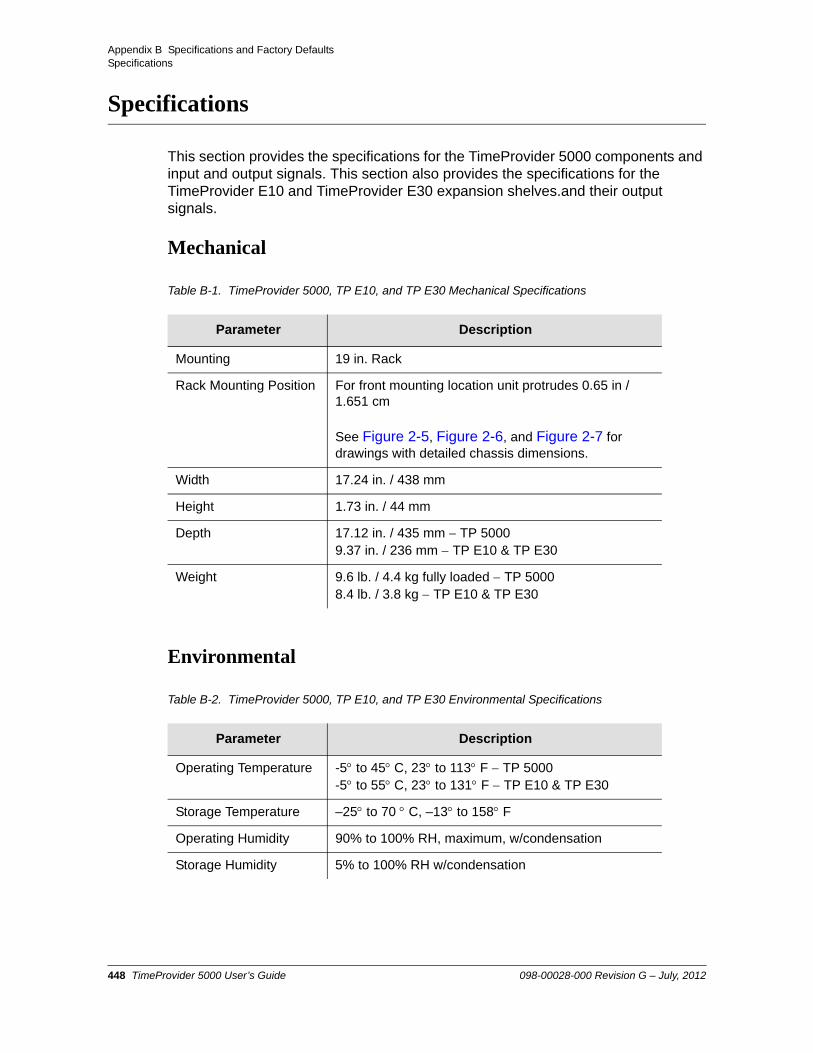
Appendix B Specifications and Factory DefaultsSpecifications
Specifications
This section provides the specifications for the TimeProvider 5000 components and input and output signals. This section also provides the specifications for the TimeProvider E10 and TimeProvider E30 expansion shelves.and their output signals.
Mechanical
Environmental
Table B-1. TimeProvider 5000, TP E10, and TP E30 Mechanical Specifications
Parameter Description
Mounting 19 in. Rack
Rack Mounting Position For front mounting location unit protrudes 0.65 in / 1.651 cm
See Figure 2-5, Figure 2-6, and Figure 2-7 for drawings with detailed chassis dimensions.
Width 17.24 in. / 438 mm
Height 1.73 in. / 44 mm
Depth 17.12 in. / 435 mm TP 50009.37 in. / 236 mm TP E10 & TP E30
Weight 9.6 lb. / 4.4 kg fully loaded TP 50008.4 lb. / 3.8 kg TP E10 & TP E30
Table B-2. TimeProvider 5000, TP E10, and TP E30 Environmental Specifications
Parameter Description
Operating Temperature -5 to 45C, 23 to 113 F TP 5000-5 to 55C, 23 to 131 F TP E10 & TP E30
Storage Temperature –25 to 70 C, –13 to 158 F
Operating Humidity 90% to 100% RH, maximum, w/condensation
Storage Humidity 5% to 100% RH w/condensation
448 TimeProvider 5000 User’s Guide 098-00028-000 Revision G – July, 2012

Appendix B Specifications and Factory DefaultsSpecifications
Power
TimeProvider 5000 Main Shelf Power Specifications
Parameter Description
DC Input Power –48 VDC / –60 VDC nominal, 0.75 A typical(0.6A for -60VDC)
DC Recommended Battery Feed Fuse
5 A, maximum
DC Power 43 W, typical
Table B-3. TimeProvider E10 Expansion Shelf Power Specifications
Parameter Description
DC Input Power –48 VDC / –60 VDC nominal, 0.75 A typical(0.6A for -60VDC)–38.4 VDC min, –72 VDC max
DC Recommended Battery Feed Fuse
2 A, maximum
DC Power 36 W, typical
Table B-4. TimeProvider E30 Expansion Shelf Power Specifications
Parameter Description
DC Input Power –48 VDC / –60 VDC nominal, 0.45 A typical(0.35 A for -60VDC)–38.4 VDC min, –72 VDC max
DC Recommended Battery Feed Fuse
1 A, maximum
DC Power 20 W, typical
098-00028-000 Revision G – July, 2012 TimeProvider 5000 User’s Guide 449

Appendix B Specifications and Factory DefaultsSpecifications
Serial Port
LAN Port
Input Signals
Table B-5. TimeProvider 5000 Main Shelf - Serial Port Specifications
Item Description
Connector Type 9-pin, female D connector
Connector Label Craft
Interface RS-232, data terminal equipment (DTE)
Baud Rate 57.6 Kbps
Data Bits 8
Parity Bit None
Stop Bits 1
Flow Control None
Table B-6. TimeProvider 5000 Main Shelf LAN Port Specifications
Connector Description
MGMT RJ-45 (10Base-T/100 Base-T) - Supports telnet sessions and SSH sessions over TCP/IP.
Table B-7. TimeProvider 5000 Main Shelf Input Signal Specifications
Parameter Specification
GPS
Requirement Total gain should be between 25 dB and 35 dB, including gain of antenna and loss of cable
Antenna Power 5V, typical
Interface SMA connector, female
GNSS
Requirement Total gain should be between 25 dB and 35 dB, including gain of antenna and loss of cable
450 TimeProvider 5000 User’s Guide 098-00028-000 Revision G – July, 2012

Appendix B Specifications and Factory DefaultsSpecifications
Antenna Power 5V, typical
Interface SMA connector, female
E1
Type G.703 Section 9 Framed E1 or G.703 Section 13 2048 kHz
Format CAS or CCS, CRC4 enable/disable
Impedance 75 ohms
Connector Mini-BNC coaxial, male SMB male for 090-50315-01
1PPS+TOD
Timing Relationship between 1PPS and TOD
Transmission of a TOD message starts 1 ms after the rising edge of 1PPS signal, and the transmission is completed within 500 ms, as shown in Figure B-1. This TOD message indicates the time of the current 1 PPS rising edge, and is sent at a rate of once per second.
Rise Time -1PPS Pulse 50 ns
Pulse Width 50 ms < Pulse width < 200 ms
TOD Frame TOD messages use whole 8-bit bytes for transmission, with check sum protection. Message type and message ID are used to clarify messages. Follows Big Endian convention when a field is longer than one byte, where bit 0 represents the least significant bit (LSB), and bit 0 of each byte is transmitted first. See Figure B-2.
See Table B-8 for TOD frame field descriptions.
TOD Transmission Parameters
Baud Rate: 9600Parity Check: NoneStart Bit: 1 (low level)Stop Bit: 1 (high level)Idle Frame: High levelData Bits: 8
TOD Message Encoding
Binary
Table B-7. TimeProvider 5000 Main Shelf Input Signal Specifications (Continued)
Parameter Specification
098-00028-000 Revision G – July, 2012 TimeProvider 5000 User’s Guide 451

Appendix B Specifications and Factory DefaultsSpecifications
Figure B-1. TP 5000 - Timing Relationship Between 1PPS and TOD for 1 PPS+TOD Input
Figure B-2. TP 5000 - TOD Frame Structure for 1 PPS+TOD Input
Table B-8. TP 5000 - TOD Frame Field Descriptions for 1PPS+TOD Input
Field Name Field Length Description
Sync Char 1 1 byte Part of Frame Header0x43 = ASCII character “C”
Sync Char 2 1 byte Part of Frame Header0x4D = ASCII character “M”
Class 1 byte Basic classification of TOD message
ID 1 byte Serial number of of TOD message
Length 2 bytes Length of payload only(Does not include Frame Header, Message Header, Length Field itself, or FCS)
452 TimeProvider 5000 User’s Guide 098-00028-000 Revision G – July, 2012

Appendix B Specifications and Factory DefaultsSpecifications
Payload 16 bytes Contains the message content.See Table B-9 for Time Message details.
Two TOD messages have been defined:
Time Information Message(see Table B-10 for payload contents)
Time Status Message(see Table B-11 for payload contents)
See Table B-12 for TOD message data type definitions
Frame Check Sequence (FCS)
1 byte Generating polynomial FCS is:
G(x) = x8 + x5 + x4 +1Initial value of FCS is set to 0xFF, and there is no need to negate the input data. Checksum calculation uses right-shift calculation, and there is no need to negate the output frame check data. When the frame check sequence is transmitted, the LSB (bit 0) is transmitted first.
Table B-9. Time Message Details for 1PPS+TOD Input
Message Type Class ID Length (bytes)
Time Information 0x01 0x20 16
Time Status 0x01 0x03 16
Table B-8. TP 5000 - TOD Frame Field Descriptions for 1PPS+TOD Input
Field Name Field Length Description
098-00028-000 Revision G – July, 2012 TimeProvider 5000 User’s Guide 453

Appendix B Specifications and Factory DefaultsSpecifications
Table B-10. TP 5000 - Time Information Message Payload Contents for 1PPS+TOD Input
ByteOffset
DataType
Name Units Notes
0 U4 Time of Week (TOW) seconds GPS Second time of week
4 I4 Reserved Reserved
8 U2 Week Number GPS week (GPS time), 16 bitsWhole weeks since 1980-01-06
10 I1 LeapS seconds Leap Seconds (GPS-UTC)
11 U1 1PPS Status 0x00 = normal
0x01 = Time sync equipment (atomic clock)in holdover mode)
0x02 = do not use
0x03 = Time sync equipment (high-stability crystal clock)in holdover mode)
0x04 = Transport carrier equipment in holdover mode)
Other values are reserved
12 U1 TAcc PPS jitter category (0 255):0 = 0 ns
1 = 15 ns
2 = 30 ns
3 = 45 ns....
255 =not defined
Note: This value is fixed to 255 for transmission and base station equipment
13 U1 Reserved Reserved
14 U1 Reserved Reserved
15 U1 Reserved Reserved
454 TimeProvider 5000 User’s Guide 098-00028-000 Revision G – July, 2012
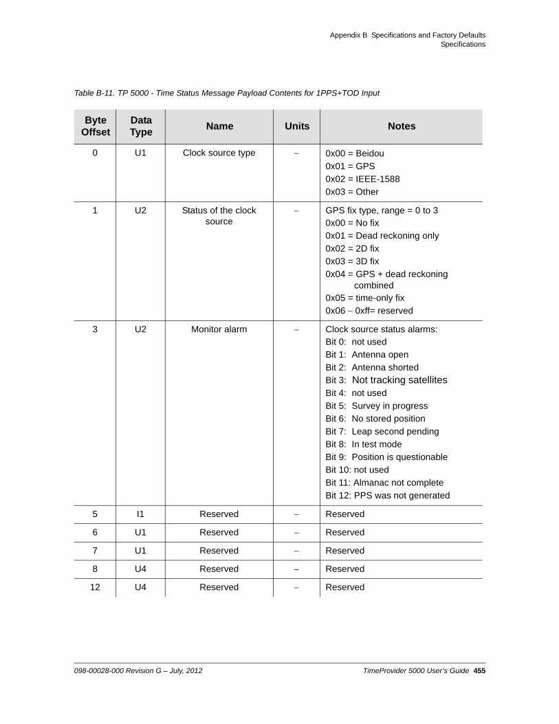
Appendix B Specifications and Factory DefaultsSpecifications
Table B-11. TP 5000 - Time Status Message Payload Contents for 1PPS+TOD Input
ByteOffset
DataType
Name Units Notes
0 U1 Clock source type 0x00 = Beidou
0x01 = GPS
0x02 = IEEE-1588
0x03 = Other
1 U2 Status of the clock source
GPS fix type, range = 0 to 30x00 = No fix
0x01 = Dead reckoning only
0x02 = 2D fix
0x03 = 3D fix
0x04 = GPS + dead reckoning combined
0x05 = time-only fix
0x06 0xff= reserved
3 U2 Monitor alarm Clock source status alarms:Bit 0: not used
Bit 1: Antenna open
Bit 2: Antenna shorted
Bit 3: Not tracking satellitesBit 4: not used
Bit 5: Survey in progress
Bit 6: No stored position
Bit 7: Leap second pending
Bit 8: In test mode
Bit 9: Position is questionable
Bit 10: not used
Bit 11: Almanac not complete
Bit 12: PPS was not generated
5 I1 Reserved Reserved
6 U1 Reserved Reserved
7 U1 Reserved Reserved
8 U4 Reserved Reserved
12 U4 Reserved Reserved
098-00028-000 Revision G – July, 2012 TimeProvider 5000 User’s Guide 455

Appendix B Specifications and Factory DefaultsSpecifications
Table B-12. TP 5000 - TOD Message Data Type Definitions for 1PPS+TOD Input
Short TypeSize
(bytes)Range Resolution Comments
U1 Unsigned Char 1 0 to 255 1
I1 Signed Char 1 -128 to 127 1 2’s complement
U2 Unsigned Short 2 0 to 65535 1
I2 Signed Short 2 -32768 to 32767 1 2’s complement
U4 Unsigned Long 4 0 to 4,294,967,295 1
I4 Signed Long 4 -2,147,483,648 to
2,147,483,647
1
R4 IEEE 754 Single Precision
4 -1 x 2127
to
2 x 2127
Value x 2-24
R8 IEEE 754 Double Precision
8 -1 x 21023
to
2 x 21023
Value x 2-53
CH ASCII / ISO8859.1 Encoding
1
456 TimeProvider 5000 User’s Guide 098-00028-000 Revision G – July, 2012

Appendix B Specifications and Factory DefaultsSpecifications
Output Signals
TP 5000 Main Shelf Output Signal Specifications
TP 5000 Main Shelf Output Signal Specifications
Parameter Specification
PTP
Ports Ethernet Small Form-factor Pluggable (SFP)Optical 1000 Base-XElectrical 100/1000 Base-T
E1
Type G.703 Section 9 Framed E1 or G.703 Section 13 2048 kHz
Format CAS or CCS, CRC4 enable/disable
Impedance 75 ohms
Connector Mini-BNC or SMB coax
10 MHz
Impedance 50 unbalanced
Amplitude 1.5 dBm to 4.5 dBm
Signal type Sine
Connector Mini-BNC
Long-term Frequency Stability <0.01 ppb, when locked to PRC/GPS
Phase Noise (minimum) 1 Hz: 60 dBc/Hz
10 Hz: 80 dBc/Hz
100 Hz: 100 dBc/Hz
1 kHz: 110 dBc/Hz
10 kHz: 140 dBc/Hz
100 kHz: 145 dBc/Hz
1PPS
Impedance 50 unbalanced
Amplitude 2.0 Vpp
Signal type Square Wave
Rise Time < 20 ns
Connector Mini-BNC
Pulse Width 5 s ±10%
098-00028-000 Revision G – July, 2012 TimeProvider 5000 User’s Guide 457

Appendix B Specifications and Factory DefaultsSpecifications
Long-term Frequency Stability <0.01 ppb, when locked to PRC/GPS
Phase Error <100 ns, when locked to GPS
TP 5000 Main Shelf Output Signal Specifications (Continued)
Parameter Specification
458 TimeProvider 5000 User’s Guide 098-00028-000 Revision G – July, 2012

Appendix B Specifications and Factory DefaultsSpecifications
TP E10 Expansion Shelf Output Signal Specifications
Table B-13. TP E10 Expansion Shelf Output Signal Specifications
Parameter Specification
PTP
Ports Ethernet Small Form-factor Pluggable (SFP)Optical 1000 Base-XElectrical 100/1000 Base-T
AccuracySystem tracking GPS or Beidou GNSS
System tracking 1PPS+TOD input
The difference between the PTP outputs and UTC time 200 ns
The difference between the PTP outputs and input time < 50 ns
SyncE
Ports Ethernet Small Form-factor Pluggable (SFP)Optical 1000 Base-X
(SyncE is only accessible on Ports 1-16 with optical SFP)
1PPS
Impedance 50 unbalanced
Amplitude 2.0 Vpp
Signal type Square Wave
Rise Time < 20 ns
Connector SMB, male
Pulse Width 5 s ±10%
Long-term Frequency Stability <0.01 ppb, when locked to PRC/GPS
1PPS Output Stability
System tracking GPS or Beidou GNSS
System tracking 1PPS+TOD input
MTIE and TDEV meet the specifications defined in ITU-T G.811, with observation time of 10,000 seconds.
MTIE and TDEV meet the specifications defined for Type I clock in ITU-T G.812, with observation time of 10,000 seconds.
Phase Error <100 ns, when locked to GPS
098-00028-000 Revision G – July, 2012 TimeProvider 5000 User’s Guide 459

Appendix B Specifications and Factory DefaultsSpecifications
TP E30 Expansion Shelf Output Signal Specifications
Table B-14. TP E30 Expansion Shelf Output Signal Specifications
Parameter Specification
E1
Type G.703 Section 9 Framed E1 or G.703 Section 13 2048 kHz
Format CAS or CCS, CRC4 enable/disable
Impedance 75 ohms
Connector SMB coaxial, unbalanced, male
1PPS+TOD
Timing Relationship between 1PPS and TOD
Transmission of a TOD message starts 1 ms after the rising edge of 1PPS signal, and the tramission is completed within 500 ms, as shown in Figure B-3. This TOD message indicates the time of the current 1 PPS rising edge, and is sent at a rate of once per second.
Rise Time -1PPS Pulse 50 ns
Pulse Width 50 ms < Pulse width < 200 ms
TOD Frame TOD messages use whole 8-bit bytes for transmission, with check sum protection. Message type and message ID are used to clarify messages. Follows Big Endian convention when a field is longer than one byte, where bit 0 represents the least significant bit (LSB), and bit 0 of each byte is transmitted first. See Figure B-4.
See Table B-15 for TOD frame field descriptions.
TOD Transmission Parameters Baud Rate: 9600Parity Check: NoneStart Bit: 1 (low level)Stop Bit: 1 (high level)Idle Frame: High levelData Bits: 8
Connector RJ-45
460 TimeProvider 5000 User’s Guide 098-00028-000 Revision G – July, 2012

Appendix B Specifications and Factory DefaultsSpecifications
Figure B-3. TP E30 - Timing Relationship Between 1PPS and TOD for 1 PPS+TOD Outputs
Figure B-4. TP E30 - TOD Frame Structure for 1 PPS+TOD Outputs
Table B-15. TP E30 - TOD Frame Field Descriptions for 1PPS+TOD Output
Field Name Field Length Description
Sync Char 1 1 byte Part of Frame Header0x43 = ASCII character “C”
Sync Char 2 1 byte Part of Frame Header0x4D = ASCII character “M”
Class 1 byte Basic classification of TOD message
ID 1 byte Serial number of of TOD message
Length 2 bytes Length of payload only(Does not include Frame Header, Message Header, Length Field itself, or FCS)
098-00028-000 Revision G – July, 2012 TimeProvider 5000 User’s Guide 461

Appendix B Specifications and Factory DefaultsSpecifications
Payload 16 bytes Contains the message contentSee Table B-16 for Time Message details.
Two TOD messages have been defined:
Time Information Message(see Table B-17 for payload contents)
Time Status Message(see Table B-18 for payload contents)
See Table B-19 for TOD message data type definitions
Frame Check Sequence (FCS)
1 byte Generating polynomial FCS is:
G(x) = x8 + x5 + x4 +1Initial value of FCS is set to 0xFF, and there is no need to negate the input data. Checksum calculation uses right-shift calculation, and there is no need to negate the output frame check data. When the frame check sequence is transmitted, the LSB (bit 0) is transmitted first.
Table B-16. Time Message Details for 1PPS+TOD Outputs
Message Type Class ID Length (bytes)
Time Information 0x01 0x20 16
Time Status 0x01 0x03 16
Table B-15. TP E30 - TOD Frame Field Descriptions for 1PPS+TOD Output
Field Name Field Length Description
462 TimeProvider 5000 User’s Guide 098-00028-000 Revision G – July, 2012

Appendix B Specifications and Factory DefaultsSpecifications
Table B-17. TP E30 - Time Information Message Payload Contents for 1PPS+TOD Outputs
ByteOffset
DataType
Name Units Notes
0 U4 Time of Week (TOW) seconds GPS Second time of week
4 I4 Reserved Reserved
8 U2 Week Number GPS week (GPS time), 16 bitsWhole weeks since 1980-01-06
10 I1 LeapS seconds Leap Seconds (GPS-UTC)
11 U1 1PPS Status 0x00 = normal
0x01 = Time sync equipment (atomic clock)in holdover mode)
0x02 = do not use
0x03 = Time sync equipment (high-stability crystal clock)in holdover mode)
0x04 = Transport carrier equipment in holdover mode)
Other values are reserved
12 U1 TAcc PPS jitter category (0 255):0 = 0 ns
1 = 15 ns
2 = 30 ns
3 = 45 ns....
255 =not defined
Note: This value is fixed to 255 for transmission and base station equipment
13 U1 Reserved Reserved
14 U1 Reserved Reserved
15 U1 Reserved Reserved
098-00028-000 Revision G – July, 2012 TimeProvider 5000 User’s Guide 463

Appendix B Specifications and Factory DefaultsSpecifications
Table B-18. TP E30 - Time Status Message Payload Contents for 1PPS+TOD Outputs
ByteOffset
DataType
Name Units Notes
0 U1 Clock source type 0x00 = Beidou
0x01 = GPS
0x02 = IEEE-1588
0x03 = Other
1 U2 Status of the clock source
GPS fix type, range = 0 to 30x00 = No fix
0x01 = Dead reckoning only
0x02 = 2D fix
0x03 = 3D fix
0x04 = GPS + dead reckoning combined
0x05 = time-only fix
0x06 0xff= reserved
3 U2 Monitor alarm Clock source status alarms:Bit 0: not usedBit 1: Antenna openBit 2: Antenna shortedBit 3: Not tracking satellitesBit 4: not usedBit 5: Survey in progressBit 6: No stored positionBit 7: Leap second pendingBit 8: In test modeBit 9: Position is questionableBit 10: not usedBit 11: Almanac not completeBit 12: PPS was not generated
5 U1 Reserved Reserved
6 U1 Reserved Reserved
7 U1 Reserved Reserved
8 U4 Reserved Reserved
12 U4 Reserved Reserved
464 TimeProvider 5000 User’s Guide 098-00028-000 Revision G – July, 2012

Appendix B Specifications and Factory DefaultsSpecifications
Clocks
Table B-19. TP E30 - TOD Message Data Type Definitions for 1PPS+TOD Outputs
Short TypeSize
(bytes)Range Resolution Comments
U1 Unsigned Char 1 0 to 255 1
I1 Signed Char 1 -128 to 127 1 2’s complement
U2 Unsigned Short 2 0 to 65535 1
I2 Signed Short 2 -32768 to 32767 1 2’s complement
U4 Unsigned Long 4 0 to 4,294,967,295 1
I4 Signed Long 4 -2,147,483,648 to
2,147,483,647
1 2’s complement
R4 IEEE 754 Single Precision
4 -1 x 2127
to
2 x 2127
Value x 2-24
R8 IEEE 754 Double Precision
8 -1 x 21023
to
2 x 21023
Value x 2-53
CH ASCII / ISO8859.1 Encoding
1
Table B-20. TimeProvider 5000 IOC Clock Specifications
Parameter Description
Quartz (Type I)
Holdover < 1 x 10⁻¹⁰/day or 10 sec over 1 day
Rubidium (Type II)
Holdover < 1 x 10-11/day or 10 sec over 5 days
098-00028-000 Revision G – July, 2012 TimeProvider 5000 User’s Guide 465

Appendix B Specifications and Factory DefaultsFactory Defaults
Factory Defaults
TP 5000 Main Shelf Defaults
Table B-21. General and Communication Parameters
Description Default Value Value Range
Reference Mode(Replaces Time-of-Day Source)
Time Time | Frequency
Time-of-Day Source(This parameter has been deprecated and will be removed in v2.0)
GPS GPS | SYS
Telnet Firewall Block Allow | Block
ICMP Firewall Allow Allow | Block
SSH Firewall Allow Allow | Block
SNMP Firewall Allow Allow | Block
FTP Firewall Block Allow | Block
SFTP Firewall Allow Allow | Block
User #1 Name admin 20 ASCII Characters
User #1 Password symmadmin** 32 ASCII Characters, a Minimum of 8
User #1 Access level admin user | config |admin
IMC EIA-232 Port 57.6k-8-N-1 fixed
IMC IP Mode Static DHCP | Static
IMC IP State Enable Enable | Disable
IMC IP Address 192.168.0.100 Valid IPv4 Address
IMC Gateway Address 0.0.0.0 Valid IPv4 Address, where value of 0.0.0.0 is used for no gateway
IMC Network Mask 255.255.255.0 Valid IPv4 Mask
Intra-System Communication Class
B: 172.16.250.8 to
172.16.250.63
IP address ranges: A: 10.0.250.8 to 10.0.250.63
B: to 172.16.250.63C: 192.168.250.8 to 192.168.250.63
IMC Exp-IF ETH State Enable (v1.3)Disable (v2.0)
Enable | Disable
IMC Exp-IF DTI State Enable Enable | Disable
466 TimeProvider 5000 User’s Guide 098-00028-000 Revision G – July, 2012

Appendix B Specifications and Factory DefaultsFactory Defaults
IMC Monitor (Exp0 - Exp9) Disable Enable | Disable
Hostname TP5000 20 ASCII Characters
Image None 1, 2
Asset Number None 20 ASCII Characters
SNMP Manager (Up to 3) None Address: Valid IPv4 AddressEngine ID: Max of 32 ASCII Characters
SNMP User (Up to 10) None Username: Max of 20 ASCII CharactersSecurity Level: noauth, auth, privAuth Type: MD5, SHAAuth Key: Max of 32 ASCII Characters,
Min of 8 ASCII CharactersPrivacy Protocol: DES, AESPrivacy Key : Max of 32 ASCII
Characters, Minimum of 8
SNMP Trap User (Up to 3) None Username: Max of 20 ASCII CharactersSecurity Level: noauth, auth, privateAuth Type: MD5, SHAAuth Key: Max of 32 ASCII Characters
Min of 8 ASCII CharactersPrivacy Protocol: DES, AESPrivacy Key : Max of 32 ASCII
Characters, Minimum of 8
SNMP v2 Community (Up to 10)
None Name: Max of 20 ASCII CharactersAccess: read-only | read-write
SNMP Trap Version 2 2, 3
SNMP v2 State Enable Enable | Disable
SNMP Trap MIB Version 1.2 1.2 | 2.0
SNMP SYS OBJ MIB 2.0 1.2 | 2.0
UTC to TAI offset 34 20 to 255
RADIUS Authentication Disable Enable | Disable
RADIUS Server IP Address 0.0.0.0 Valid IPv4 Address
RADIUS Server Key None Max of 32 ASCII characters
RADIUS UDP Port 1812 1024 to 65535
Remote Syslog Host 0.0.0.0 Valid IPv4 Address
Table B-21. General and Communication Parameters (Continued)
Description Default Value Value Range
098-00028-000 Revision G – July, 2012 TimeProvider 5000 User’s Guide 467

Appendix B Specifications and Factory DefaultsFactory Defaults
Remote Syslog State Disable Enable | Disable
Local Alarm Log Buffer Size 100 0 to 100 Kbytes
Local Event Log Buffer Size 100 0 to 100 Kbytes
Local Command Log Buffer Size
100 0 to 100 Kbytes
Local Security Log Buffer Size
100 0 to 100 Kbytes
Auto-Sync Enable Enable | Disable
Bridging Time 900 100 to 100000
Table B-22. GPS, GNSS, and Input Port Parameters
Description Default Value Value Range
GPS State Enable Enable | Disable
GPS Priority 2 1 to 16
GPS Antenna Cable Delay 0 0 to 999,999 ns
GPS Position Mode Auto Auto | Manual
GPS Position Lat - N37:22:43.425
Long - W121:55:34.815Elevation - 13.7m
LAT = Ndd:mm:ss.ss or Sdd:mm:ss.sss
LONG = Eddd:mm:ss.ss or Wddd:mm:ss.sss
ELEV= ±hhhh.h height in meters,-999.9 to 40,000.0 meters
GPS Elevation Mask 10 5 to 45 degrees
GPS PQL State Disable Enable | Disable
GPS PQL Value 1 1 to 3
GNSS State Enable Enable | Disable
GNSS Priority 1 1 to 16
GNSS Antenna Cable Delay 0 0 to 65,485 ns
GNSS Position Mode Auto Auto | Manual
Table B-21. General and Communication Parameters (Continued)
Description Default Value Value Range
468 TimeProvider 5000 User’s Guide 098-00028-000 Revision G – July, 2012

Appendix B Specifications and Factory DefaultsFactory Defaults
GNSS Position Lat - N37:22:43.425
Long - W121:55:34.815Elevation - 13.7m
LAT = Ndd:mm:ss.ss or Sdd:mm:ss.sss
LONG = Eddd:mm:ss.ss or Wddd:mm:ss.sss
ELEV= ±hhhh.h height in meters,-999.9 to 40,000.0 meters
GNSS Elevation Mask 10 5 to 45 degrees
GNSS Track Mode Priority-GPS Beidou | GPS | Priority-GPS | Priority Beidou
GNSS PQL State Disable Enable | Disable
GNSS PQL Value 1 1 to 3
1PPS+TOD Input Port 1 State Enable Enable | Disable
1PPS+TOD Input Port 1 Priority 3 1 - 16
1PPS+TOD Input Port 1 PQL State
Disable Enable | Disable
1PPS+TOD Input Port 1 PQL Value
1 1 to 3
1PPS+TOD Input Port 1 Cable Delay
0 0 - 200,000 ns
1PPS+TOD Input Port 2 State Enable Enable | Disable
1PPS+TOD Input Port 2 Priority 4 1 - 16
1PPS+TOD Input Port 2 PQL State
Disable Enable | Disable
1PPS+TOD Input Port 2 PQL Value
1 1 to 3
1PPS+TOD Input Port 2 Cable Delay
0 0 - 200,000 ns
Reference Criteria Priority Priority | SSM (see note below)
Telecom Input Port 1 State Enable Enable | Disable
Telecom Input Port 1 Priority 7 1 - 16
Telecom Input Port 1 Frame Type
freq2048khz D4 | ESF | CCS | CAS | freq2048khz | freq1544khz
Telecom Input Port 1 CRC Disable Enable | Disable
Telecom Input Port 1 SSM State
Disable Enable | Disable(see note below)
Table B-22. GPS, GNSS, and Input Port Parameters (Continued)
Description Default Value Value Range
098-00028-000 Revision G – July, 2012 TimeProvider 5000 User’s Guide 469

Appendix B Specifications and Factory DefaultsFactory Defaults
Telecom Input Port 1 SSM Bit 8 4 | 5 | 6 | 7 | 8
Telecom Input Port 1 SSM PQL Value
3 1 to 9
Telecom Input Port 2 State Enable Enable | Disable
Telecom Input Port 2 Priority 8 1 to 16
Telecom Input Port 2 Frame Type
freq2048khz D4 | ESF | CCS | CAS | freq2048khz | freq1544khz
Telecom Input Port 2 CRC Disable Enable | Disable
Telecom Input Port 2 SSM State
Disable Enable | Disable(see note below)
Telecom Input Port 2 SSM Bit 8 4 | 5 | 6 | 7 | 8
Telecom Input Port 2 SSM PQL Value
3 1 to 9
Note: The reference criterion MANUAL is no longer supported. Only PRIORITY and SSM are supported for reference selection.
Manual selection of a reference input can be done by disabling all reference input ports except the desired one.
The “set ref override” command is no longer supported.
Table B-23. Telecom Input / Output Parameters
Description Default Value Value Range
Telecom IO Port 1 Input Input | Output
Telecom IO Port 2 Input Input | Output
Table B-22. GPS, GNSS, and Input Port Parameters (Continued)
Description Default Value Value Range
470 TimeProvider 5000 User’s Guide 098-00028-000 Revision G – July, 2012

Appendix B Specifications and Factory DefaultsFactory Defaults
Table B-24. I/O Card Expansion Port Output Parameters
Description Default Value Value Range
I/O Exp. Port 1 - DTI Output .State Enable Enable | Disable
I/O Exp. Port 2 - DTI Output State Enable Enable | Disable
Table B-25. Telecom Output Port Parameters
Description Default Value Value Range
Telecom Output Port State Enable Enable | Disable
Telecom Output Port Frame Type (mini-BNC connector)
freq2048khz CCS | CAS | freq2048khz
Telecom Output Port Frame Type (RJ-45 connector)
freq2048khz D4 | ESF | freq1544khz
Telecom Output Port CRC Disable Enable | Disable
Telecom Output Port SSM Disable Enable | Disable
Telecom Output Port SSM Bit 8 4 | 5 | 6 | 7 | 8
Output Generation Warm-up Squelch Squelch | On | AIS
Output Generation Free-run Squelch Squelch | On | AIS
Output Generation Holdover On Squelch | On | AIS
Output Generation Fast-track On Squelch | On | AIS
Table B-26. Output Port Parameters
Description Default Value Value range
10 MHz Output Port State Enable Enable | Disable
10 MHz Output Generation Warm-up Squelch Squelch | On
10 MHz Output Generation Free-run Squelch Squelch | On
10 MHz Output Generation Holdover On Squelch | On
10 MHz Output Generation Fast-track On Squelch | On
098-00028-000 Revision G – July, 2012 TimeProvider 5000 User’s Guide 471

Appendix B Specifications and Factory DefaultsFactory Defaults
1PPS Output Port State Enable Enable | Disable
1PPS Output Generation Warm-up Squelch Squelch | On
1PPS Output Generation Free-run Squelch Squelch | On
1PPS Output Generation Holdover On Squelch | On
1PPS Output Generation Fast-track On Squelch | On
Table B-27. PTP Grand Master Port IP Parameters
Description Default Value Value Range
IOC1-y IP AddressIOC1-1
IOC1-2
192.168.1.11192.168.2.11
Valid IPv4 Address
IOC1-y IP Mask 255.255.255.0 Valid IPv4 Mask
IOC1-y IP Gateway 0.0.0.0 Valid IPv4 Address, special value of 0.0.0.0 is used for no gateway
IOC1 Port Redundancy (Bonding)
Disable Enable | Disable
IOC IP State Enable Enable | Disable
Table B-28. VLAN Parameters - Fixed Index (116)
Description Default Value Value Range
IOCx-y AddressIOC1-1
IOC1-2
No VLAN configured Valid IPv4 Address
IOC1-y Mask No VLAN configured Valid IPv4 Mask
IOC1-y Gateway No VLAN configured Valid IPv4 Address
ID 0(not visible in VLAN table)
1 to 4094
Table B-26. Output Port Parameters (Continued)
Description Default Value Value range
472 TimeProvider 5000 User’s Guide 098-00028-000 Revision G – July, 2012

Appendix B Specifications and Factory DefaultsFactory Defaults
Table B-30. Ethernet Link Auto-negotiation Parameters
Priority 0 0 to 7
Mode Disable Enable | Disable
State Disable Enable | Disable
Table B-29. VLAN Parameters - Non-Fixed
Description Default Value Value Range
Ethernet Port Address(expansion shelf)
No VLAN configured Valid IPv4 Address
Ethernet Port Mask No VLAN configured Valid IPv4 Mask
Ethernet Port Gateway No VLAN configured Valid IPv4 Address
ID 0(not visible in VLAN table)
1 to 4094
Priority 0 0 to 7
Mode Disable Enable | Disable
State Disable Enable | Disable
Description Default Value Value Range
Auto-negotiation state Enable Enable | Disable
Auto-negotiation speed All 100M | 1000M | All
Table B-28. VLAN Parameters - Fixed Index (116)
Description Default Value Value Range
098-00028-000 Revision G – July, 2012 TimeProvider 5000 User’s Guide 473

Appendix B Specifications and Factory DefaultsFactory Defaults
Table B-31. Packet Service Parameters
Description Default Value Value Range
Packet Service ptp-gm for PTP productntp-server for NTP product
ptp-gm | ptp-probe | ntp-probe | ntp-server
Table B-32. PTP Grand Master Common Parameters
Description Default Value Value Range
PTP IOC1-y Timescale Auto Auto | PTP | Arb
PTP IOC1-y Clock Identity MAC-based value(i.e. FF:FE inserted in the middle of MAC address)
64-bit value
PTP IOC1-y Priority 1 128 0 to 255
PTP IOC1-y Priority 2 128 0 to 255
PTP IOC1-y Domain 4 for ITU-G.8265.1 profile0 for all other profiles
0 to 255
PTP IOC1-y TTL Value 64 1 to 255
PTP IOC1-y DSCP State Disable Enable | Disable
PTP IOC1-y DSCP Value 0 0 to 63
PTP Sync Limit –7 –7 to 7
PTP Announce Limit –3 –4 to 4
PTP Delay Limit –7 –7 to 7
PTP State Enable Enable | Disable
PTP Max Number of Clients 500 per port 1 to 500 per port(or 1000 if bonded ports or if other port is not running
ptp-gm)
PTP Dither Disable Enable | Disable
PTP Profile Telecom-2008 telecom-2008 | default | hybrid | itu-g8265-1
PTP Two Step Disable Enable | Disable
PTP MGMT Addr Mode Unicast Unicast | Multicast
PTP Alternate Master Disable Enable | Disable
474 TimeProvider 5000 User’s Guide 098-00028-000 Revision G – July, 2012
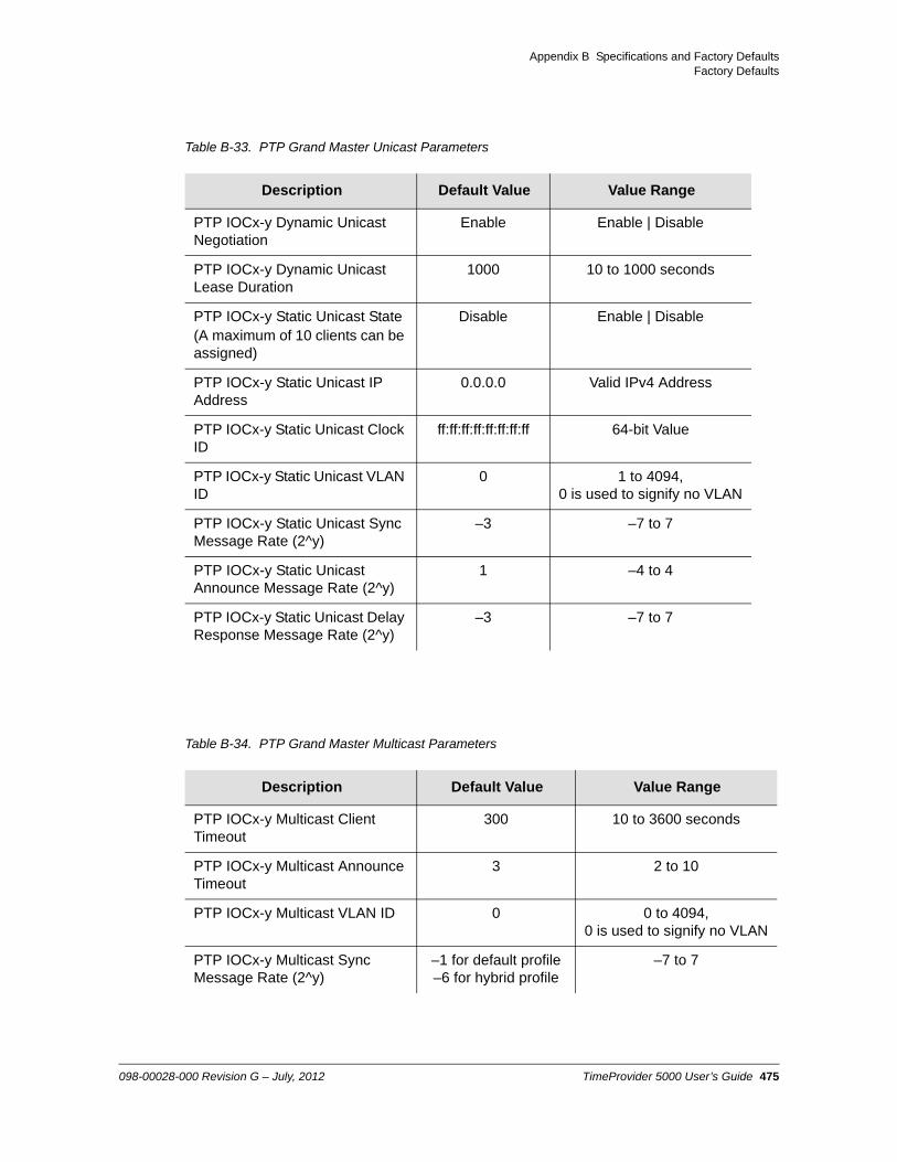
Appendix B Specifications and Factory DefaultsFactory Defaults
Table B-33. PTP Grand Master Unicast Parameters
Description Default Value Value Range
PTP IOCx-y Dynamic Unicast Negotiation
Enable Enable | Disable
PTP IOCx-y Dynamic Unicast Lease Duration
1000 10 to 1000 seconds
PTP IOCx-y Static Unicast State(A maximum of 10 clients can be assigned)
Disable Enable | Disable
PTP IOCx-y Static Unicast IP Address
0.0.0.0 Valid IPv4 Address
PTP IOCx-y Static Unicast Clock ID
ff:ff:ff:ff:ff:ff:ff:ff 64-bit Value
PTP IOCx-y Static Unicast VLAN ID
0 1 to 4094,0 is used to signify no VLAN
PTP IOCx-y Static Unicast Sync Message Rate (2^y)
–3 –7 to 7
PTP IOCx-y Static Unicast Announce Message Rate (2^y)
1 –4 to 4
PTP IOCx-y Static Unicast Delay Response Message Rate (2^y)
–3 –7 to 7
Table B-34. PTP Grand Master Multicast Parameters
Description Default Value Value Range
PTP IOCx-y Multicast Client Timeout
300 10 to 3600 seconds
PTP IOCx-y Multicast Announce Timeout
3 2 to 10
PTP IOCx-y Multicast VLAN ID 0 0 to 4094,0 is used to signify no VLAN
PTP IOCx-y Multicast Sync Message Rate (2^y)
–1 for default profile–6 for hybrid profile
–7 to 7
098-00028-000 Revision G – July, 2012 TimeProvider 5000 User’s Guide 475

Appendix B Specifications and Factory DefaultsFactory Defaults
PTP IOCx-y Multicast Announce Message Rate (2^y)
1 –4 to 4
PTP IOCx-y Multicast Delay Response Message Rate (2^y)
–7 –7 to 7
Table B-35. NTP Server Parameters
Description Default Value Value Range
NTP IOC1-y State Enable Enable | Disable
NTP IOC1-y TTL Value 64 1 to 255
NTP IOC1-y DSCP State Disable Enable | Disable
NTP IOC1-y DSCP Value 0 0 to 63
NTP IOC1-y Transaction Rate Limit
20,000 transactions/second
120,000 or 20,000 NTP transactions/second by license
NTP VLAN ID 2 1 to 4094
Note: The NTP Server feature can either be ordered in a new system, or added to a previously ordered system as a field upgrade. Field upgrades require a license activation key. Contact your Symmetricom representative for more information.
Table B-36. PTP Grand Master Multicast Parameters
Description Default Value Value Range
Active Probe GM IPIOC1-1
IOC1-2
192.168.1.11192.168.2.11
Valid IPv4 Address
Active Probe VLAN ID No VLAN 1 - 4094
Active Probe GM Clock ID ff:ff:ff:ff:ff:ff:ff:ff 64-bit value
Table B-34. PTP Grand Master Multicast Parameters
Description Default Value Value Range
476 TimeProvider 5000 User’s Guide 098-00028-000 Revision G – July, 2012

Appendix B Specifications and Factory DefaultsFactory Defaults
Table B-37. SSM Settings
TP E10 Expansion Shelf Defaults
Active Probe Interval -6 if using CLI commands
0 in TimeMonitor
PDV (20 =1)
-6 to 7
Active Probe Duration 300 10 to 1000 seconds
Description Default Value Value Range
SSM Option Option 1 Option 1 | Option 2
Table B-38. TP E10 - Expansion Port Parameters
Description Default Value Value Range
Exp-IF DTI Port State Enable Enable | Disable
Table B-36. PTP Grand Master Multicast Parameters (Continued)
Description Default Value Value Range
098-00028-000 Revision G – July, 2012 TimeProvider 5000 User’s Guide 477

Appendix B Specifications and Factory DefaultsFactory Defaults
Table B-39. TP E10 - PTP Output Port IP Parameters
Description Default Value Value Range
IP AddressPort 1Port 2Port 3Port 4Port 5Port 6Port 7Port 8Port 9Port 10Port 11Port 12Port 13Port 14Port 15Port 16
192.168.21.11192.168.22.11192.168.23.11192.168.24.11192.168.25.11192.168.26.11192.168.27.11192.168.28.11192.168.29.11192.168.30.11192.168.31.11192.168.32.11192.168.33.11192.168.34.11192.168.35.11192.168.36.11
Valid IPv4 Address
Port x IP Mask 255.255.255.0 Valid IPv4 Mask
Port x IP Gateway 0.0.0.0 Valid IPv4 Address
Port x IP State Enable Enable | Disable
478 TimeProvider 5000 User’s Guide 098-00028-000 Revision G – July, 2012

Appendix B Specifications and Factory DefaultsFactory Defaults
Table B-40. TP E10 - VLAN Parameters
Description Default Value Value Range
Port x Addressx= 1 - 16 192.168.21.11
192.168.22.11192.168.23.11192.168.24.11192.168.25.11192.168.26.11192.168.27.11192.168.28.11192.168.29.11192.168.30.11192.168.31.11192.168.32.11192.168.33.11192.168.34.11192.168.35.11192.168.36.11
Valid IPv4 Address
Port x Mask 255.255.255.0 Valid IPv4 Mask
Port x Gateway 0.0.0.0 Valid IPv4 Address
ID 2 1 to 4094
Priority 0 0 to 7
Mode Disable Enable | Disable
Table B-41. TP E10 - Ethernet Auto Negotiation Parameters
Description Default Value Value Range
ETH Auto Negotiation State Enable Enable | Disable
ETH Auto Negotiation Speed All 100M | 1000M | All
098-00028-000 Revision G – July, 2012 TimeProvider 5000 User’s Guide 479

Appendix B Specifications and Factory DefaultsFactory Defaults
Table B-42. TP E10 - Expansion Shelf PTP Parameters
Description Default Value Value Range
PTP Port x State Enable Enable | Disable
PTP Timescale Auto PTP | ARB | Auto
PTP Two-Step Clock Disable Enable | Disable
PTP Alternative Master Disable Enable | Disable
PTP Priority 1 128 0 to 255
PTP Priority 2 128 0 to 255
PTP Domain 0 0 to 255
PTP Dither Disable Enable | Disable
PTP Clock Identity MAC-based value(i.e. FF:FE inserted in the middle of
MAC address)
64-bit value
PTP Multicast Sync Interval 0 7 to 7
PTP Multicast Announce Interval 1 4 to 4
PTP Multicast Delay Interval 7 7 to 7
PTP Multicast Announce Timeout 3 2 to 10
PTP Multicast Client Timeout 300 10 to 3600 sec
Table B-43. TP E10 - Output Port Parameters
Description Default Value Value range
SyncE Ethernet Synchronization Messaging Channel (ESMC)
Disable Enable | Disable
Enabled SyncE/PTP ports 8 ports(Port 1-8)
8 ports | 16 ports
Note: The second set of SyncE/PTP ports (Ports 9-16) for the TP E10 expansion shelf are available as a purchasable option.
480 TimeProvider 5000 User’s Guide 098-00028-000 Revision G – July, 2012
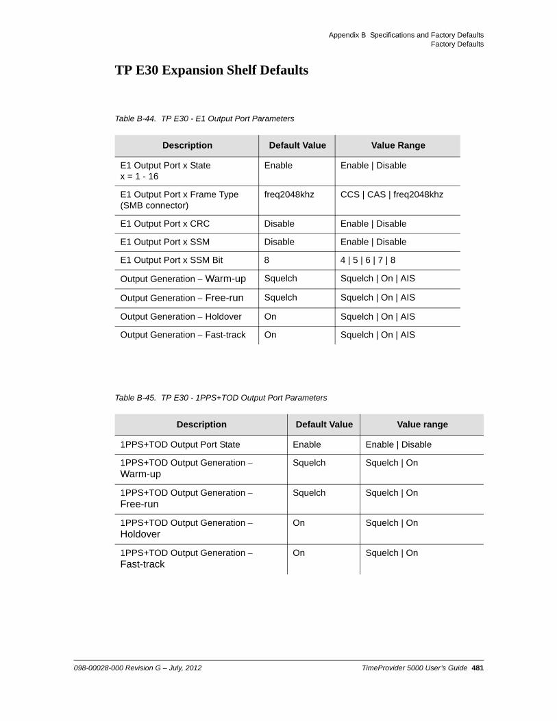
Appendix B Specifications and Factory DefaultsFactory Defaults
TP E30 Expansion Shelf Defaults
Table B-44. TP E30 - E1 Output Port Parameters
Description Default Value Value Range
E1 Output Port x Statex = 1 - 16
Enable Enable | Disable
E1 Output Port x Frame Type (SMB connector)
freq2048khz CCS | CAS | freq2048khz
E1 Output Port x CRC Disable Enable | Disable
E1 Output Port x SSM Disable Enable | Disable
E1 Output Port x SSM Bit 8 4 | 5 | 6 | 7 | 8
Output Generation Warm-up Squelch Squelch | On | AIS
Output Generation Free-run Squelch Squelch | On | AIS
Output Generation Holdover On Squelch | On | AIS
Output Generation Fast-track On Squelch | On | AIS
Table B-45. TP E30 - 1PPS+TOD Output Port Parameters
Description Default Value Value range
1PPS+TOD Output Port State Enable Enable | Disable
1PPS+TOD Output Generation Warm-up
Squelch Squelch | On
1PPS+TOD Output Generation Free-run
Squelch Squelch | On
1PPS+TOD Output Generation Holdover
On Squelch | On
1PPS+TOD Output Generation Fast-track
On Squelch | On
098-00028-000 Revision G – July, 2012 TimeProvider 5000 User’s Guide 481

Appendix B Specifications and Factory DefaultsFactory Defaults
Alarm Default Values
Table B-46. GPS Port Alarm Parameters
Description Default Value Value Range
Alarm Delay Time 0 0 to 500000
Alarm State (for each alarm) Enable Enable | Disable
Alarm Severity Level See System Notification Messages, on page 425
2 to 5
482 TimeProvider 5000 User’s Guide 098-00028-000 Revision G – July, 2012

Appendix C Installing the GPS Antenna
The GPS L1 Reference Antenna is one component of a complete line of GPS accessories for your GPS antenna system provided by Symmetricom. These accessories are designed to deliver precise GPS signals over a wide temperature range and in harsh environmental conditions.
In This Document
Antenna Kits and Accessories
Installing the Antenna
098-00028-000 Revision G – July, 2012 TimeProvider 5000 User’s Guide 483

Appendix C Installing the GPS AntennaAntenna Kits and Accessories
Antenna Kits and Accessories
This section provides a list of antenna kits and accessories as well as descriptions and associated part numbers.
To order any accessory, contact the Symmetricom Sales Department. See http://www.symmetricom.com/company/contact-information/sales-offices for sales support contact information.
Selecting the Proper Gain Antenna
When installing the GPS radio receiver, it is important to select the proper gain antenna and coaxial cable that accounts for the insertion loss between the antenna and the radio receiver to avoid under-driving or over-driving the radio receiver antenna input. The gain required at 1575 MHz for a GPS radio receiver input is the manufacturer’s specification for the radio receiver to acquire satellites, with some level of signal degradation allowed.
L1 Antenna gains are usually specified as the minimum effective gain. Such antenna gains can have 4.5 to 10 dB more signal strength at different satellite azimuths and elevations, depending on their reception pattern. The GPS engine requires a net gain at the antenna connector input of the chassis (GPS or GNSS port) to be between 25 dB and 35 dB. This tolerance allows for the signal loss of the internal and external coaxial cable and connectors. The optimal gain at the GPS radio receiver input is 30 dB. The total gain is the gain of the GPS antenna less the loss of the transient eliminator, connectors, and cables.
All antenna kits include the GPS L1 antenna, mounting pipe, floor flange, transient eliminator, pre-assembled coaxial cable (for antenna to transient eliminator), roll of 3M 2150 weatherproof tape, and a right angle adapter. The antennas, transient eliminators, and in-line amplifiers have N-type connectors.
All antenna kits supplied use LMR-400, or equivalent, low-loss coaxial cable. Other types of coaxial cable are available for GPS antenna applications; however, it is imperative that you calculate the specific cable loss to ensure a gain between 25 dB and 35 dB at the antenna connector input. The L1 signal loss of LMR-400 is 0.167 dB/meter. The L1 signal loss of a 90 V transient eliminator is typically 0.25 dB.
GPS Antenna Kits With Low Noise Amplifiers, 26, 40, or 48 dBSymmetricom offers three versions of GPS antennas with 26, 40, or 48 dB total Low Noise Amplifier (LNA) gain. These antenna kits, which are compatible with most commercial GPS receivers, receive, amplify, and filter the L1 (1575.42 MHz) signal from GPS satellites. The antenna is housed in a weatherproof package suitable for permanent installation in an exposed location. For additional transient eliminator protection requirements, you can install a 250B-90 Gas Tube transient eliminator in series with the antenna coaxial cable.
484 TimeProvider 5000 User’s Guide 098-00028-000 Revision G – July, 2012

Appendix C Installing the GPS AntennaAntenna Kits and Accessories
The cable between the antenna and the TimeProvider 5000 cable should be kept to the shortest reasonable length. Before using additional cables, verify that the total antenna system gain is acceptable as described in the Selecting the Proper Gain Antenna section of Appendix D. The tables listed below provide information about the antenna:
Table C-1 lists the item number and provides a brief description of each antenna
Table C-2 provides specification information for GPS antenna with internal LNA
Table C-3 lists the item numbers and provides a brief description of the antenna accessories available for the GPS series antennas.
Table C-2 provides specifications for GPS antennas with internal LNA.
Table C-1. GPS Antennas with Internal LNA
Part Number Description Minimum Cable Length
990-13091-006 26 dB Antenna with 3 m + 3 m cable 3 m (10 ft)
990-13091-013 26 dB Antenna with 3 m + 10 m cable 3 m (10 ft)
990-13073-070 40 dB Antenna with 10 m + 60 m cable 30 m (100 ft)
990-13074-150 48 dB Antenna with 10 m + 140 m cable 76 m (250 ft)
990-13075-230 48 dB Antenna with 10 m + 220 m cable and 20 dB Amplifier
198 m (650 ft)
Table C-2. Specifications for GPS Antennas with Internal LNA
Characteristic Specification
Mechanical
Mounting 4 holes, 1.75 in x 1.75 in (4.445 cm x 4.445 cm) centers, 0.25 in (0.635 cm) mounting holes
Diameter 3.5 in (88.9 mm)
Height 12.94 in (328.7 mm), including pipe mount
Weight < 3 lbs (1.4 kg)
Environmental
Temperature –40C to +75C
Relative Humidity 100% Non-Immersed
Altitude 200 ft. (60 m) below sea level to 13,000 ft. (3962 m) above sea level
Electrical
Power 4.7 to 28 VDC (5 VDC Nominal)
098-00028-000 Revision G – July, 2012 TimeProvider 5000 User’s Guide 485

Appendix C Installing the GPS AntennaAntenna Kits and Accessories
Table C-3 lists the available accessories for GPS antennas with internal LNA.
Transient Eliminators
Symmetricom offers the FCC-250B-90-1.5NFNF Transient Eliminator for installations that require antenna coaxial lead-in protection. The FCC-250B- 90-1.5NFNF Transient Eliminator passes DC power and frequencies in the 1.5 GHz range with non-downconverter L1 GPS antennas. In most installations, the transient eliminator mounts near the point at which the antenna lead enters the facility. Table C-4 provides the transient eliminator specifications.
Element Right Hand Circular
Carrier L1 (1545.42 MHz)
Bandwidth 10 MHz
Noise Figure < 2.5 dB
Output Impedance 50
GainMarine 26Marine 40Marine 50
26.5 dB 3 dB40 dB minimum48 dB minimum
Table C-3. 26 dB L1 GPS Antenna Accessory Kit
Part Number Description
112-43400-00-3 Transient Eliminator, 90 Volts, 1.5 GHz, N-Type
12010210-000-0 Bracket Assembly, Antenna Mount Right Angle
12813080-000-0 Crimper Kit, LMR-400 (crimp tool, 2150 tape, LMR preptool, 10 each crimp N-type connectors)
Table C-4. FCC-250B-90-1.5NFNF Specifications
Characteristic Specification
Type Gas
Response Time < 2 nanoseconds
Impedance 50
Table C-2. Specifications for GPS Antennas with Internal LNA (Continued)
Characteristic Specification
486 TimeProvider 5000 User’s Guide 098-00028-000 Revision G – July, 2012

Appendix C Installing the GPS AntennaAntenna Kits and Accessories
GPS L1 Inline Amplifier
The GPS L1 Inline Amplifier (570704-0002) option boosts the signal from the antenna. Use this amplifier on LMR-400 cables that are longer than 650 feet; it receives power from the GPS radio receiver through the antenna coaxial cable connections. Table C-5 provides mechanical and electrical specifications for the amplifier.
Insertion Loss < 0.25dB @ 1,575 MHz
VSWR < 1.6:1 @ 1,575 MHz
DC Breakdown Voltage 90 Volts
Dissipation Capacity 10,000 Amperes, impulse 8/20 µsec
Connector Type N-Type
Temperature –55C to + 70C
Relative Humidity 100% Non-immersed
Altitude 200 ft. (60 m) below sea level to 13 000 ft. (3962 m) above sea level
Table C-5. GPS L1 Inline Amplifier Specifications
Characteristic Specification
Mechanical
Connectors, (In/Out) N-Type
Gain 20 dB 2 dB
Dimensions, includes connectors Length: 3.77 in (9.6 cm)
Electrical
Power +4 VDC to +28 VDC
Current < 10 mA
Noise Factor < 3 dB
Table C-4. FCC-250B-90-1.5NFNF Specifications (Continued)
Characteristic Specification
098-00028-000 Revision G – July, 2012 TimeProvider 5000 User’s Guide 487

Appendix C Installing the GPS AntennaAntenna Installation
Antenna Coaxial Cables
Symmetricom provides several low-loss cable types, as well as LMR-400 with N-type connectors on both ends. Before using additional cables, verify that the total antenna system gain is acceptable as described in the Selecting the Proper Gain Antenna section of Appendix D.
Table 6-10 in Chapter 6 of this User’s Guide lists the optional antenna coaxial cables
Table C-6 provides antenna cable specifications
Antenna Installation
This section provides a procedure for installing a GPS antenna. Before beginning the installation, review Planning the Installation, on page 489, and gather the necessary tools and materials described in Antenna Installation Tools and Materials, on page 492
Table C-6. Antenna Cable Specifications
Cable TypeMeasured Loss (@1.575 GHz dB
per foot)
DC Resistance ( per foot)
Type Center Conductor
Flammability
RG213/U(Belden 8267)
0.093 dB 0.0030 Stranded 13 AWG U/L CSA
RG213/U(Belden 8267)
0.093 dB 0.0030 Stranded 2.62 mm2 U/L CSA
UHF/VHF(Belden 9913)
0.058 dB 0.0027 Solid 10 AWG
UHF/VHF(Belden 9913)
0.058 dB 0.0027 5.26 mm2
UHF/VHF(Belden 89913)
0.089 dB 0.0027 Solid 10 AWG Plenum U/L CSA
UHF/VHF(Belden 89913)
0.089 dB 0.0027 5.26 mm2 Plenum U/L CSA
LMR-400 0.051 dB Shield – 0.00165Center – 0.00139
0.109 inch Solid
LMR-400 0.051 dB Shield – 0.00165 Center – 0.00139
0.27686 cm2 Solid
488 TimeProvider 5000 User’s Guide 098-00028-000 Revision G – July, 2012

Appendix C Installing the GPS AntennaAntenna Installation
Antenna Connection Overview
The TimeProvider 5000 chassis has one antenna connection located on the front of the IMC module. The antenna connection is made via a SMA connector, labeled GPS. The connectors are DC isolated and AC bypassed to frame ground. This connection is used for a radio receiver antenna connection only. Installation procedures for GPS antennas are outlined below.
Planning the Installation
Prior to installing the antenna, you should plan the site, antenna location, grounding scheme, cable route, and all other details.
Locating the AntennaUse Figure C-1 as a guide to locating the antenna.
Figure C-1. Locating the GPS Antenna
Caution: To avoid damage to the GPS antenna, do not place the antenna where high-power radio signals are beamed directly at the unit. Such signals can damage the preamplifier of the GPS antenna.
098-00028-000 Revision G – July, 2012 TimeProvider 5000 User’s Guide 489

Appendix C Installing the GPS AntennaAntenna Installation
Warning: To avoid serious injury to personnel or damage to equipment, exercise caution when working near high voltage lines. In particular:
Use extreme caution when installing the GPS antenna near, under, or around high voltage lines.
Follow local building electrical codes for grounding using the frame ground lug on the TimeProvider 5000 chassis.
The in-line amplifier receives 5 VDC power from the GPS radio receiver, and is supplied on the center conductor of the LMR-400 or equivalent coaxial cable. If the application requires an in-line amplifier, mount the amplifier/plate assembly where the transient eliminator would normally be mounted.
Symmetricom does not recommend cutting the antenna cables provided in the GPS Antenna Kit.
Recommendation: Symmetricom recommends that you consider the following location and environment influences before installing the GPS antenna:
If possible, provide the antenna with an unobstructed 360-degree view of the sky from the horizon.
In general, do not allow obstructions that obscure the horizon (as viewed from the antenna) by more than 10 degrees, as shown in Figure C-1.
Locate the antenna well away from, and preferably in a plane above electrical equipment such as elevators, air conditioners, or other machinery.
To reduce the risk of lightning damage, do not place the antenna at the highest point of the building.
Locate the GPS antenna at least 12 feet from metallic objects, if possible.
Locate the antenna high enough to avoid drifted snow.
Locate the transient eliminator in a protected area to avoid contact with standing water.
Locate the antenna within 30 feet of the point at which the antenna cable enters the building.
Allow at least 10 feet of separation distance between GPS antennas.
Surfaces above the plane of the unit that are between the antenna and the horizon can produce reflected (multi-path) signals, which can degrade the performance of the radio receiver.
490 TimeProvider 5000 User’s Guide 098-00028-000 Revision G – July, 2012

Appendix C Installing the GPS AntennaAntenna Installation
Developing a Grounding SchemeIn addition to determining where to locate and mount the antenna and cabling, you should develop a grounding scheme. The purpose of the grounding scheme is to provide some protection against voltage surges and static discharge. If transient eliminators are used, they also need to be connected to the perimeter ground system or bulkhead entrance panel that is connected to the perimeter ground system.
In general, follow local building codes when selecting a grounding scheme, wire size, and installation.
Use #6 AWG (13.3 mm) copper ground wire or larger, depending on the distance to the earth ground electrode. Refer to your local electrical codes for specific details. In most cases, 1/0 AWG (55.0 mm) ground wire will maintain 1/10 the resistance of the coaxial shied..
Connect transient eliminators, if part of the grounding scheme, to earth ground through a conductor.
Symmetricom makes no recommendation as to whether to install transient eliminators. Symmetricom can provide suitable transient eliminators as an option.
Never connect antenna systems to the same earth ground connector as heating and cooling systems, elevator or pump motors, or other motors or machinery which can induce noise in the antenna system.
Caution: To ensure proper grounding, observe these precautions when installing the antenna:
Allow no sharp bends in the ground conductors.
Ensure that no painted surface insulates the transient eliminator or grounding clamps.
Ensure that ground conductors are bonded to the metal enclosure box (if used) and do not enter through an access hole.
Do not use soldered connections for grounding purposes.
Secure all grounding connections with mechanical clamp type connectors.
Note: Larger ground conductors provide better transient elimination; that is, the larger the ground conductor, the less likely the chance of transients.
Note: Do not connect the outside transient eliminator ground to the inside equipment rack ground. Doing so can defeat the protection afforded by the transient eliminator.
098-00028-000 Revision G – July, 2012 TimeProvider 5000 User’s Guide 491

Appendix C Installing the GPS AntennaAntenna Installation
Antenna Installation Tools and Materials
These standard tools and materials are not supplied in the antenna kit, but may be required for installing the GPS antenna. For a list of antenna kit contents, see Table C-1.
Four each 0.25 in (6 mm) fasteners for installing the antenna floor flange
Extra cable ties or acceptable cable clamps
#6 AWG (minimum) copper ground wire
Eight-foot (2.9 m) ground electrode
Custom mounting plates, U-bolts, masonry bolt, and so forth, as needed for mounting to a tower, roof, or wall of a building
A cable puller may be required for installing the antenna coaxial cable
Digital voltmeter (DVM)
Cutting Antenna Cables
Symmetricom recommends that you coil excess cable to avoid gain mismatch between the GPS antenna and the radio receiver. Coiling the excess cable also allows you to use the factory-installed crimped connector.
Symmetricom does not recommend cutting the antenna cables provided in the GPS Antenna Kits. If you must cut the cables, please ensure that the following requirements are met.
Be aware of these cable and connector requirements before cutting antenna cables:
Cable Requirements – The total cable length from the radio receiver to the antenna must not be shorter than the minimum cable lengths indicated in the GPS Antenna Kits (see Table C-1).
Connector Requirements – The cables provided with the GPS Antenna Kit have factory installed crimped connectors. If you cut these cables, you must supply and add a connector. Symmetricom recommends that you use only crimp-style N-type connectors in the Crimper Kit for this application.
Caution: To prevent damage to connectors, use caution while pulling cable.
Caution: To avoid damage to the connectors, do not use the connectors to pull the cable. If at all possible, avoid bundling the coaxial cable with other cables (and possible noise sources). Use appropriate cable-pulling devices when pulling the coaxial cable through conduit or a weather head.
492 TimeProvider 5000 User’s Guide 098-00028-000 Revision G – July, 2012

Appendix C Installing the GPS AntennaAntenna Installation
Installing the Antenna
This section provides installation procedures for installing the GPS antenna.
Figure C-2. GPS Antenna Installation
To mount the GPS antenna:
To mount the antenna to any stable flat surface, use the floor flange supplied in the GPS Antenna Kit. The mounting surface and the local building codes determine the type and number of fasteners, screws, bolts, and so forth, that may be required.
To mount the antenna on the side of a building or tower, use the optional right angle mounting bracket (part number 12010210-000-0).
To secure the coaxial cable to the mast, use one or more 8-inch cable ties or appropriate cable clamps.
Connecting the Cable to the Antenna
To connect the coaxial cable to the mounted antenna (see Figure C-2):
Note: Follow local building electrical codes when installing the GPS antenna.
098-00028-000 Revision G – July, 2012 TimeProvider 5000 User’s Guide 493

Appendix C Installing the GPS AntennaAntenna Installation
1. Loosen the four screws securing the top of the antenna in place to gain access to the connector.
2. Route the shorter antenna coaxial cable from the antenna through the floor flange (in the lower half of the antenna base) to the unit.
3. Connect the cable to the antenna and run the cable from the antenna through the slot of the floor flange.
4. Replace the four screws to secure the top of the antenna in place with the cable connected.
Installing the Transient Eliminator
If you are installing a transient eliminator, follow these guidelines:
Transient eliminators should be installed in accordance with your antenna system grounding scheme
Mount the transient eliminator within 30 feet (9 m) of the GPS antenna
If required, mount a second transient eliminator near the GPS antenna
To install the transient eliminator:
1. If necessary, cut the coaxial cable and install mating connectors (see Cutting Antenna Cables, on page 492).
2. Using the DVM, measure the resistance between the center conductor and shield to verify that the center conductor and shield are not shorted together.
3. Connect the longer GPS antenna coaxial cable to the transient eliminator.
Caution: To avoid damage to the connectors, do not use the connectors to pull the cable. If at all possible, avoid bundling the coaxial cable with other cables (and possible noise sources). Use appropriate cable-pulling devices when pulling the coaxial cable through conduit or a weather head.
Caution: To avoid damage to internal solder connections, do not over-tighten the connector.
Note: Step 6 in the following procedure cannot be done if you cut the cable (as described in Step 1).
494 TimeProvider 5000 User’s Guide 098-00028-000 Revision G – July, 2012

Appendix C Installing the GPS AntennaAntenna Installation
4. Connect the ground wire between the transient eliminator and the proper grounding zone (building ground, master ground bar, or other) for the mounting location.
5. Wrap the connectors with weatherproof tape for added protection.
6. Verify that the antenna coaxial cable center conductor is not shorted to the shield of the cable.
Installing the Antenna Cable
You should install the antenna cable from the transient eliminator to the TimeProvider 5000 using the shortest route possible. Follow all applicable building and electrical codes to ensure a water-tight and fire-resistant installation. .
Connecting the GPS Antenna
Before connecting the GPS antenna to the TimeProvider 5000, see Antenna Connection Overview, on page 489. Then, follow the instructions below.
1. Verify that the center conductor is not shorted to the shield.
If the reading shows a short or open, you may have a shorted or open cable or transient eliminator (if installed). Therefore, apply the same measurements directly to the GPS antenna. This requires disconnecting the antenna cable at the antenna.
Recommendation: Symmetricom does not recommend soldered connections for grounding purposes. All grounding connections should be secured with mechanical clamp connectors.
Caution: To avoid damage to the connectors, do not use the connectors to pull the cable. If at all possible, avoid bundling the cable with other cables (and possible noise sources). Use appropriate cable-pulling devices when pulling the cable through conduit or a weather head.
Note: The open-circuit range of an individual ohmmeter can cause readings to vary among meters.
098-00028-000 Revision G – July, 2012 TimeProvider 5000 User’s Guide 495

Appendix C Installing the GPS AntennaAntenna Installation
2. Secure the free end of the antenna cable to the appropriate antenna connector on the rear panel of the TimeProvider 5000 using the right angle adapter provided with the antenna cable.
Antenna Installation Completeness Checklist
To verify that antenna installation is complete:
Verify that all power and ground wires are installed correctly and securely fastened.
Verify that all input and output cables are properly installed.
Verify that all antenna connectors are secure, tight, and weatherproofed.
Recommendation: Symmetricom recommends coiling excess cable to avoid gain mismatch between the GPS antenna and the TimeProvider 5000. Coiling the excess cable also allows you to use the factory-installed crimped connector.
496 TimeProvider 5000 User’s Guide 098-00028-000 Revision G – July, 2012

Appendix D Redundant IOC Cards
In This Appendix
Overview
Parameters with IOC Card Redundancy
Causes of Switchovers Between IOC Cards
Setting the Active IOC Card at Power Up
Output Performance During Switchover
IOC Card Redundancy-Related CLI Commands
098-00028-000 Revision G – July, 2012 TimeProvider 5000 User’s Guide 497

Appendix D Redundant IOC CardsOverview
Overview
The TimeProvider 5000 chassis has two IOC card slots, IOC1 and IOC2, as shown in Figure D-1. In v1.0, the TP5000 could only support a single IOC card, which had to be installed in the IOC1 position. In v1.1, the Redundant IOC Cards feature was introduced to the TP5000.
Figure D-1. IOC Card Placements in TP5000 Chassis
If the TP5000 v1.1 is configured with two IOC cards, the IOC cards will automatically operate redundantly. (There is no capability for the user to disable redundancy.) With redundancy, one card is Active and drives outputs, while the other is in Standby mode. Both cards share the same configuration, IOC1, so both IOC cards will have the same IP addresses and Clock IDs for the Ethernet ports on either card, but with different MAC addresses for each IOC card. Neither card is primary and redundancy is not revertive. However, IOC1 will be the active IOC if the entire system is rebooted or powered-up, and preference is given to a Rb IOC on initial warmup.
If the TP5000 v1.1 is configured with one IOC card, the card can be located in either the IOC1 or IOC2 position.
On system power-up, IOC1 will be active. After initial warm-up of both cards is complete, the IOC with the Rb oscillator will be active, even if it is IOC2. If the active IOC card fails, exhibits certain diminished health conditions, or loses its Ethernet connection, the TP5000 will switch over to the standby card within 10 seconds. The configuration and state is synchronized between cards automatically. The user can also use a CLI command or SNMP (if SNMP option is purchased) to initiate a manual switchover.
Note: The IOC with the Rb oscillator is initially selected as the Active IOC after power-up of the system, regardless of its position as IOC1 or IOC2.
498 TimeProvider 5000 User’s Guide 098-00028-000 Revision G – July, 2012

Appendix D Redundant IOC CardsParameters with IOC Card Redundancy
Parameters with IOC Card Redundancy
Both of the redundant IOC cards share the same configuration, IOC1, so both IOC cards will have the same IP addresses and Clock IDs for the Ethernet ports on either card. Each PTP port on each IOC card has a unique MAC address, but it may not be used in the port redundancy mode.
IP Addresses and MAC Addresses with Independent Ports
The IP address for the ETH1 port will be the same for IOC1 and IOC2, as shown in Figure D-2.
The IP address for the ETH2 port will be the same for IOC1 and IOC2.
Each port on each IOC card will retain a unique MAC address, regardless of IOC redundancy. See Figure D-2
IP Addresses and MAC Addresses with Port Redundancy
If Port Redundancy (Bonding) is enabled, interface bond0 will be added on both redundant IOCs. ETH1 and ETH2 will become the slave interface of bond0. Interface bond0 will use the ETH1 MAC address and ETH1 IP address. As slave interfaces, ETH1 and ETH2 will not carry an IP address. ETH1 will use its own MAC address, while ETH2 will use the ETH1 MAC address. The redundant IOC bond0 interface will have the same IP address as the active IOC. However, the MAC addresses of bond0, ETH1, and ETH2 will use the MAC address of ETH1 of its own card. See Figure D-3.
Clock IDs
Clock IDs normally self-generate for IOC ports using the MAC-based method described in IEEE-1588. Essentially, the Clock ID is generated by inserting the two bytes “FFFE” between the first 3 bytes and last 3 bytes of the MAC. For example, a MAC of “00:b0:ae:01:90:ea” will have a Clock ID of “00:b0:ae:ff:fe:01:90:ea”. In non-port-redundant mode, the independent ETH1 and ETH2 ports of an IOC use the Clock IDs associated with their individual MAC addresses. See Figure D-2.
Note: To avoid unexpected behavior if port redundancy is disabled, assign the IP addresses for ETH1 and ETH2 to different subnets.
098-00028-000 Revision G – July, 2012 TimeProvider 5000 User’s Guide 499

Appendix D Redundant IOC CardsParameters with IOC Card Redundancy
With IOC card redundancy, the Clock IDs are generated from the MAC addresses for the ETH1 and ETH2 ports of the IOC card that was Active first. The first Active card is typically the card in the IOC1 slot, as described in the section Setting the Active IOC Card at Power Up, on page 503. If a switchover occurs, the Standby card will become the Active card and use the Clock ID of the original Active IOC.
As long as a TP5000 chassis continuously has a powered IOC module in it (assuming that the IOC has been powered long enough to take on Clock IDs), the chassis will maintain the same Clock IDs for ETH1 and ETH2.
The Clock ID can also be manually assigned by the user with the CLI command "set ptp clockid" command or via SNMP.
Clock IDs with IOC Card Redundancy and Port RedundancyIn port redundancy mode, IOC1 and IOC2 will share a single Clock ID. The bond0 port uses the MAC address of ETH1 and therefore the clock ID is based on the ETH1 MAC address. See Figure D-3. In such a case, the chassis will maintain a single Clock ID as long as a chassis continuously has a powered IOC module in it .
Figure D-2. Redundant IOC Cards With Independent Ethernet Ports
500 TimeProvider 5000 User’s Guide 098-00028-000 Revision G – July, 2012

Appendix D Redundant IOC CardsCauses of Switchovers Between IOC Cards
Figure D-3. Redundant IOC Cards With Redundant (Bonded) Ethernet Ports
Possible Conflicts With Clock IDs and IP Addresses
As previously described, when the chassis contains two IOCs, the standby IOC takes on general configuration from the active IOC, including the Clock ID associated with the active IOC. In the event that one IOC card is removed and installed as a single IOC card in a different TP5000 chassis, a conflict can ensue because both TP5000s will be using the same Clock IDs and IP addresses. (If the IOC is placed in a TP5000 chassis that already has an Active IOC, the inserted IOC will take on the Clock IDs and IP addresses of the Active IOC.)
This issue can be avoided by issuing the “set configuration default” command to the TP5000 with the newly installed IOC card before putting the unit into service as a Grandmaster. All IOC parameters will be reset to default values (see Appendix B of the TP5000 User’s Guide for descriptions of default values), but user logins and communication attributes, such as IP addresses of the MGMT port on the IMC, will be preserved. The Clock ID will be generated from the MAC addresses for the ETH1 and ETH2 ports of the active IOC card. The IP addresses for ETH1 and ETH2 will need to be reconfigured, as well as the PTP parameters
Causes of Switchovers Between IOC Cards
A switchover is when the TP5000 switches the active card to the standby state, while also switching the standby card to the active state. The active IOC card sends a gratuitous ARP after switchover. Switchovers between IOC cards are non-revertive.
There are two possible causes for switchovers between IOC cards on the TP5000: emergency/health situations and planned switchovers.
098-00028-000 Revision G – July, 2012 TimeProvider 5000 User’s Guide 501

Appendix D Redundant IOC CardsCauses of Switchovers Between IOC Cards
Emergency Switchovers
The TP5000 continuously monitors the health of both the active and standby IOC cards. The TP5000’s switchover algorithms associate certain priority ranks (Symmetricom-assigned) for different health conditions to determine which IOC is healthiest at any time. If the TP5000 determines that the health of the IOC in the Active state is worse than the health of the IOC in the Standby state, the TP5000 will switch over the Active card to Standby, and vice-versa. The TP5000 will complete the switch over to the standby card within 10 seconds. If the detected condition for an Active card has a priority rank of “Failed”, the Standby card will be switched to Active, but the Active card will be not become the Standby card because it has become non-functional.
The TP5000 uses the Symmetricom-assigned priority ranks for the conditions or alarms to determine switchover. The IOC switchover process will not be affected by user changes to the alarm enable/disable state or severity.
The top priority rank category includes failures that are not recoverable. Items that are ranked as lower priority include internal conditions or alarms that may recover. The lowest priority rank includes loss-of-link of the IOC Ethernet ports. The Ethernet link status is the only external condition that will cause an automatic switchover.
Planned Switchovers
By CommandThe user can also manually initiate a change to switch the states of the Active and Standby cards.
First, use the command show ioc-state to display which IOC card is in the Active state.
Example:
tp5000> show ioc-state
Response:
---------------------------------|Module ID |State ||---------------|---------------||ioc1 |active ||...............|...............||ioc2 |standby |---------------------------------
502 TimeProvider 5000 User’s Guide 098-00028-000 Revision G – July, 2012

Appendix D Redundant IOC CardsSetting the Active IOC Card at Power Up
Next, use the command set ioc-state to switch over the Standby card to an Active state.
Example:
If IOC2 is in a Standby state, the command to change it to an Active state is
tp5000> set ioc-state ioc2 active
Rubidium “One-Time” SwitchoverAnother type of planned switchover can occur in a mixed-performance IOC TP5000, where one IOC card has a Rb oscillator and the other IOC has an OCXO. Symmetricom assumes that the user prefers the higher-performance Rb IOC to be active in such a case. If a lower-performance IOC is Active when an Rb IOC card first becomes capable of normal operation (whether from power-up or reboot), the TP5000 will perform a one-time switchover to make the IOC with a Rb oscillator become the Active card.
Setting the Active IOC Card at Power Up
If an IOC card is installed in the IOC1 slot of the TP5000 chassis, the TP5000 will start the state machine for the IOC1 card to determine its appropriate state. If two IOC cards are installed in a TP5000 at power-up, the TP5000 will start the start the state machine for IOC2 one minute after starting the state machine IOC1, as shown in Figure D-4. IOC1 will normally complete the warm-up process before IOC2, barring any health issues with IOC1, which means that IOC1 will initially be the Active card.
After the IOC2 card has completed the warm-up process, the TP5000 will select the IOC with the Rb oscillator as the Active IOC. If IOC1 has the Rb oscillator, there will be no switchover. If IOC2 has the Rb oscillator, rather than OCXO, the TP5000 will initiate a switchover to make IOC2 the Active card.
Note: If an Active IOC is physically removed from a TP5000 that has a redundant IOC configuration, two transient events will be generated in the event log:
IOCx NOT PRESENT
IOCx TRANSITIONED TO ACTIVE STATE.
There will be no alarms.
098-00028-000 Revision G – July, 2012 TimeProvider 5000 User’s Guide 503

Appendix D Redundant IOC CardsSetting the Active IOC Card at Power Up
Figure D-4. IOC Condition at Power Up
IOC States
The possible states for an IOC card are Active, Standby, Active Warmup, Standby Warmup, Fail, Non-existent, and Disabled.
The TP5000’s IOC state machine uses proprietary algorithms to determine the proper state for an IOC card. Table D-1 describes aspects of the state machine, such as possible IOC states, the next possible state, and the conditions required for the next state transition.
Table D-1. IOC States and Related Conditions
IOC STATE
Description Possible Next State
Conditions Required For Next State Transition
Allowed State of Other IOC
Initial
(Not an actual state)
The IOC has powered up or rebooted and is ready to decide its first state.
Active Warmup
The IOC State of other IOC card is: Standby Warmup
Standby
Fail
Non-existent
-------------
Standby Warmup
The IOC State of other IOC card is: Active Warmup
Active
504 TimeProvider 5000 User’s Guide 098-00028-000 Revision G – July, 2012

Appendix D Redundant IOC CardsSetting the Active IOC Card at Power Up
Active Warmup
This IOC is warming up and will become the active IOC
Active Oscillator warmup completion criteria attained
If GPS is selected reference, all GPS validation has been completed and time has been set
Standby Warmup
Fail
Non-existent
Standby Warmup
This IOC is warming up and will become the standby IOC
Standby IOC has synchronized its configuration from the other IOC
Oscillator warmup completion criteria attained
If GPS is selected reference, all GPS validation has been completed and time has been set
Other IOC is Active
Active Warmup
Active Warmup
Other IOC State = Standby Warmup, Standby, Fail, or Non-existent
Active This IOC is in a normal operating mode. It is actually providing all IOC user input- and output-related functions.
Standby Internally generated health reason
User-issued command to switch
Standby Warmup
Standby
Fail
Non-existent
Standby This IOC is in a normal operating mode. It is capable of providing all IOC user input- and output-related functions, but it is not Active.
Active Internally generated health reason
User-issued command to switch
Active
Table D-1. IOC States and Related Conditions (Continued)
IOC STATE
Description Possible Next State
Conditions Required For Next State Transition
Allowed State of Other IOC
098-00028-000 Revision G – July, 2012 TimeProvider 5000 User’s Guide 505

Appendix D Redundant IOC CardsOutput Performance During Switchover
Output Performance During Switchover
During switchover, the PTP outputs may be interrupted for a maximum of 10 seconds.
All continuous outputs, 10MHz, 1PPS, and E1, will not exhibit any loss of signal during switchover, but may exhibit phase movement of up to 240 ns.
Fail This IOC has experienced a serious health condition and is not operating
------------- Internal detection of serious health condition
Active Warmup
Active
Fail
Non-existent
Non-existent
There is no IOC card in this physical slot
See Initial IOC State
in this table
Insertion of IOC into this physical slot
Active Warmup
Active
Fail
Non-existent
Disabled The user has taken action to soft-reboot this IOC. This condition will temporarily exist while the IOC prepares to reboot. In this transient state, the IOC is not available to become active.
See Initial IOC State
in this table
Completion of reboot process and state decision made in Initial IOC state.
Active Warmup
Active
Fail
Non-existent
Table D-1. IOC States and Related Conditions (Continued)
IOC STATE
Description Possible Next State
Conditions Required For Next State Transition
Allowed State of Other IOC
506 TimeProvider 5000 User’s Guide 098-00028-000 Revision G – July, 2012

Appendix D Redundant IOC CardsIOC Card Redundancy-Related CLI Commands
IOC Card Redundancy-Related CLI Commands
The following CLI commands are related to IOC card redundancy.
show ioc-state
set ioc-state
set ptp clockid
Show PTP-config common clock-id
098-00028-000 Revision G – July, 2012 TimeProvider 5000 User’s Guide 507

Appendix D Redundant IOC CardsIOC Card Redundancy-Related CLI Commands
508 TimeProvider 5000 User’s Guide 098-00028-000 Revision G – July, 2012

Appendix E Software Licenses
This product contains licensed third party software, including software available under the GPL licensing scheme. The text of each license is available in the “License” folder located on the Product Information CDROM that is supplied with the TimeProvider 5000. Additionally, you can obtain these licenses and the open-source software by contacting Symmetricom Technical support at the following numbers:
Worldwide (Main Number): 1-408-428-7907
USA, Canada, Latin America including Caribbean, Pacific Rim including Asia, Australia and New Zealand: 1-408-428-7907
USA toll-free: 1-888-367-7966 (1-888-FOR-SYMM)
Europe, Middle East & Africa: 49 700 32886435
An administrative fee may be charged to obtain the source code.
By using the TimeProvider 5000, the user agrees to the terms of these licenses.
In This Appendix
Third-Party Software
098-00028-000 Revision G – July, 2012 TimeProvider 5000 User’s Guide 509

Appendix E Software LicensesThird-Party Software
Third-Party Software
The following is a list of third-party software applications provided with the TimeProvider 5000.
busybox
dropbear
dtc
elfutils-libelf-libs
ethtool
expect
glibc
iproute
iptables
libgcc
libpcap-libs
libxml
linux-2.6.20
logrotate
mtd-utils
net-snmp
openssl
pam-libs
pam-modules
pam_radius
popt-libs
sudo
syslogd
tcl-dev
tcpdump
tftpd-hpa
u-boot
wget
zlib-libs
510 TimeProvider 5000 User’s Guide 098-00028-000 Revision G – July, 2012

Appendix F PTP Probe Option
This appendix describes the procedures for installing, provisioning, and operating the TimeProvider 5000 in Probe mode.
In This Appendix
Overview
Requirements for Measurements
Installing the Probe
Controlling the Probe With TimeMonitor PDV
Provisioning the Probe
– Enable the Probe Option on the TP 5000
– Enable Port as a PTP Probe
– Return Port to Grandmaster Mode
– Set the IP Address for Probe MGMT Port
– Set Probe IP Address
– Set Grandmaster PTP IP Address
– Set Synchronization Interval
– Set Lease Duration
Operating the Probe
Probe Data
Analyzing Probe Data
098-00028-000 Revision G – July, 2012 TimeProvider 5000 User’s Guide 511

Appendix F PTP Probe OptionOverview
Overview
The Precision Time Protocol (PTP) is a time-transfer protocol defined in the IEEE 1588-2008 standard that allows distribution of time and frequency over packet switched networks. A PTP server (master) and PTP client (slave) devices exchange synchronization messages at regular intervals. These messages are time-stamped by the server and clients, so each client can recompute the offset between its clock and the server's clock. See Figure F-1.
Symmetricom’s TP 5000 PTP Probe (an optional operational mode of the TP 5000) provides a way to examine the packet delay of synchronization messages passing through a packet switched network. Using a hardware time-stamp processor that delivers nanosecond caliber-timing accuracy, a comprehensive computation engine, and TimeMonitor software, the TP 5000 PTP Probe collects PTP data and analyzes in real-time and off-line graphical displays. See Figure F-2. The Probe simulates a PTP client device. It negotiates with the Grandmaster server for PTP flows, follows the PTP protocol as a client device, and sends delay-request packets. Unlike a normal client, it does not adjust its clock, but only time stamps the received packets using its own clock. Performance of the network can be measured relative to the location of the Probe device and traffic conditions. By measuring Packet Delay Variation (PDV), users can characterize a network and determine its suitability for delivering sync packets. Measurements include PDV and packet Minimum Time Deviation (MinTDEV).
The PTP probe mode supports three profiles:
Default: Multicast Layer 3 of 7-layer model
Ethernet-Default: Multicast Layer 2 of 7-layer model
Telecom-2008: Unicast
The PDV module of the TimeMonitor software suite also features a set of six masks in the packet domain that correspond to the masks in the synchronization domain, as defined by Telecommunication standards. The six masks available for packetTDEV and packetZTIE analysis cover application requirements ranging from synchronization interface requirements, to traffic interface requirements, to wireless backhaul frequency offset requirements. Four of the masks apply to the packetZTIE calculation and two of the masks apply to the packetTDEV calculation. These masks help determine if the PTP packet flow delivered over the network meets the synchronization criteria for the application, and allow TimeMonitor PDV to present a very intuitive and user-friendly PASS/FAIL result for the given conditions. TimeMonitor is included with the Probe option.
512 TimeProvider 5000 User’s Guide 098-00028-000 Revision G – July, 2012

Appendix F PTP Probe OptionOverview
The Probe function is an optional feature of the TimeProvider 5000. The Probe function is enabled via a special software key. If a TimeProvider 5000 is configured in Probe mode, it cannot be used in Grandmaster mode at the same time.
Figure F-1. IEEE-1588 Grandmaster Server and Client
Figure F-2. IEEE-1588 Grandmaster Server and Probe
Note: The PTP probe option must be purchased to enable the functionality of all “ptp-probe” commands.
098-00028-000 Revision G – July, 2012 TimeProvider 5000 User’s Guide 513

Appendix F PTP Probe OptionRequirements for Measurements
Requirements for Measurements
The TP 5000 1588 Probe is an active probe. No additional counters or other instruments are necessary to make measurements in packet networks. The following are required:
TimeProvider 5000 Grandmaster (or other 1588 Server with Unicast and 1-step clock)
TimeMonitor software suite (or other tools for analyzing PDV data)
Computer (terminal function or TimeMonitor)
Ethernet network connections
Optional Equipment
Traffic simulator for lab-based measurements
Installing the Probe
See Figure F-3 and Figure F-4 below for TP 5000 Probe connectors and LEDs. To physically install the TP 5000 Probe, use the following procedures from Chapter 2, Installing:
Rack Mounting the Chassis
Ground Connections
Power Connections
Control /Management Connection
– EIA-232 Serial (Craft) Port
– Ethernet Management Port
GPS Connections
See Figure F-5 for a diagram of the test setup for the TP 5000 Probe and grandmaster.
Note: Symmetricom recommends the use of GPS as the time-of-day reference for the Probe and for the Grandmaster (or other 1588 server). This will allow for sub-microsecond end-to-end analysis.
514 TimeProvider 5000 User’s Guide 098-00028-000 Revision G – July, 2012

Appendix F PTP Probe OptionInstalling the Probe
Figure F-3. TP 5000 PTP Probe Connectors and LEDs
Connecting PTP Signals to Measure
The two Ethernet 100/1000 Small-form Factor Pluggable (SFP) connections on the IOC module provide PTP inputs to the TP 5000 Probe. See Figure F-4. It is possible to monitor two different subnets, one on each port. Only the SFP transceivers in Table F-1 are recommended and supported. Other SFP transceivers are not supported and may cause the TimeProvider 5000 to not comply with regulatory requirements.
Figure F-4. Probe Input Connections - IOC Module
.
Use the following procedure to make the connections for PTP measurements:
Table F-1. Recommended and Supported SFP Transceivers
Type Transceiver
Optical 1000 Base-LX Single-Mode Ethernet 1310nm (Symmetricom 121-20621-10-2)
Avago AFCT-5701PZFinisar FTLF1319P1BTL
Optical 1000 Base-SX Multi-Mode Ethernet 850nm (Symmetricom 121-20621-11-2)
Avago AFBR-5710PZFinisar FTLF8519P2BNL
RJ45 100/1000 Base-T Full-Duplex(Symmetricom 121-20621-12-2)
Avago ABCU-5710RZ
098-00028-000 Revision G – July, 2012 TimeProvider 5000 User’s Guide 515

Appendix F PTP Probe OptionControlling the Probe With TimeMonitor PDV
1. Plug the SFP transceiver into the ETH1 or ETH2 port on the IOC module of the TP 5000 probe.
2. Plug an Ethernet cable into the SFP transceiver.
3. Plug the other end of the Ethernet cable directly into the packet network, as shown in Figure F-5.
Figure F-5. Test Setup for TP 5000 Probe (power connections not shown)
Controlling the Probe With TimeMonitor PDV
The TP 5000 Probe can also be provisioned and operated with the TimeMonitor PDV software module.
The TimeMonitor PDV Software has three major functions:
Configure the TP 5000 probe for PTP packet-timing measurement data collection.
Collect packet timing data. The file of collected data contains packet timestamps between the TP 5000 Probe and a PTP grandmaster.
516 TimeProvider 5000 User’s Guide 098-00028-000 Revision G – July, 2012

Appendix F PTP Probe OptionControlling the Probe With TimeMonitor PDV
Analyze a probe data file using packetTDEV and packetZTIE, and give a pass/fail indication using built-in masks.
When TimeMonitor PDV is launched, the main screen will appear.
Anatomy of the GUI Main Screen
The GUI main screen for TimeMonitor PDV is shown in Figure F-6, with numeric markers at the various buttons, fields and boxes. Descriptions for these buttons fields and boxes, corresponding to the numerical markers, are presented in Table F-2.
All examples for provisioning and operating the Probe will include instructions for both TimeMonitor PDV and CLI.
Figure F-6. TimeMonitor PDV GUI Main Screen
098-00028-000 Revision G – July, 2012 TimeProvider 5000 User’s Guide 517

Appendix F PTP Probe OptionControlling the Probe With TimeMonitor PDV
Table F-2. Descriptions of TimeMonitor PDV GUI Main Screen
Item Label Description
Command Sets TimeMonitor PDV to Command mode. Interaction with TimeAnalyzer's TP 5000 probe is through the buttons and fields of the GUI. Commands are issued either with buttons or the "Command" text box (see item 26). In Command mode, for example, the Login button can be used to login to TimeAnalyzer's TP 5000 probe or the Probe Address button can be used with the Probe Address/Netmask/Gateway fields (see item 6) to change the address for the selected Probe port.
Terminal Sets TimeMonitor PDV to Terminal mode. The interface will act as a simplified terminal. Commands and responses are shown in the Main Display (see Item 29). All other fields and buttons will be grayed out, except for Check, Start, and Clear buttons.
Disconnect Sets TimeMonitor PDV to Disconnect mode. Use as a quick means to Logout from TimeAnalyzer's TP 5000 probe. Must be in Disconnect mode to change between RS-232 and TCP/IP for communicating with probe, or to change communication settings (see Item 3).
Check Click Check button to verify the test setup before beginning the PDV measurements for the selected port.
Start Click Start button to start PDV measurements for the selected port.
Stop Click Stop button to stop PDV measurements for the selected port.
RS-232TCP / IP
Use these radio buttons to select the type of connection for command and control of the TP 5000 probe. Clicking the button to the right of the connection type will display the dialog box to configure the connection. TCP/IP should be used for making measurements. Either TCP/IP or RS-232 can be used for configuration.
Interval Use these radio buttons to select the desired interval rate for Sync and Delay Requests from the TP 5000 probe.
Duration Use this field to enter the desired lease duration for the TP 5000 probe
Probe'sIP AddressNetmaskGateway
Enter the IP address information for the selected TP 5000 probe port. The Command mode or Disconnect mode (see Item 1) must be selected in order to enter this data. Click the Probe Address button (see Item 14) to send this address information to the TP 5000 probe.
518 TimeProvider 5000 User’s Guide 098-00028-000 Revision G – July, 2012

Appendix F PTP Probe OptionControlling the Probe With TimeMonitor PDV
Grandmaster's IP Address
Enter the Grandmaster connection information for the selected port. The Command mode (see Item 1) or Disconnect must be selected in order to enter this data.
(Note: Netmask and Gateway information are not necessary for the Grandmaster.)
VLAN Click the check box if the Grandmaster has a VLAN address. Enter the appropriate VLAN ID in the field.
Clock ID - Master
Enter the Clock ID of the Grandmaster for the selected port.
Clock ID - Probe
Enter the Clock ID for the selected TP 5000 probe port.(Note: It is not necessary to fill in the Clock ID field for the TP 5000 probe, but it is recommended.)
Firewall Off Use this button to set the Telnet firewall for the Probe to "Allow". The default firewall state for Telnet is "Block". The Command mode (see Item 1) must be selected in order to use this button, and the user must be logged in to the TP 5000 probe.
Eth1Eth 2
Use these radio buttons to select the TP 5000 probe Ethernet port for measurements or configuration.
Probe EnableProbe Disable
Use these buttons to Enable or Disable the Probe Mode for the selected port. The Command mode (see Item 1) must be selected in order to use these buttons, and user must be logged in to the TP 5000 probe.
Probe Address This button is used to set the IP address for the selected TP 5000 probe Ethernet port using the info in the Address fields for the TP 5000 probe (see Item 6). Changes to the TP 5000 probe IP address will not be sent to the TP 5000 probe until this button is clicked. The Command mode (see Item1) must be selected in order to use this button, and user must be logged in to the TP 5000 probe.
Show Config Use this button to display the Probe configuration for both ports. The Command mode (see Item 1) must be selected in order to use this button, and user must be logged in to the TP 5000 probe.
LoginLogout
Use these buttons to login or logout from the TP 5000 probe. The Command mode (see Item 1) must be selected in order to use this button.
File The File text box is used to specify file name and destination directory. The name need only be specified once because the software will reuse a file name for new files and add on a date and time to the file name if the file already exists.
Table F-2. Descriptions of TimeMonitor PDV GUI Main Screen (Continued)
Item Label Description
098-00028-000 Revision G – July, 2012 TimeProvider 5000 User’s Guide 519

Appendix F PTP Probe OptionControlling the Probe With TimeMonitor PDV
Title Enter title for packet delay data file.
Help The Help drop-down box is used to access the Help file (this file), and get the revision level of the Symmetricom TimeMonitor PDV software.
All the information about the Help Menu is in this section and can be read by clicking on one of the subjects below to jump to a topic directly. Information about other menus can be read by selecting the menu item in the left pane and jumping to the selected topic directly. You can also click on the (<=Back) Help button to move to the most recently viewed topic.
HELP: Opens the HELP file. This file is not context sensitive. Opening the Help file will always initially display the Help with the first topic, "Introduction", in view.
README: This file contains important information about the Symmetricom TimeMonitor Measurement Software. The topics covered are either not found in other documentation or are judged to be important enough to warrant restatement.
ABOUT: Displays the Version and Revision number and other information about the Symmetricom TimeMonitor PDV Software.
SETUP: Selecting this menu item brings up a dialog box which can be used to adjust the maximum number of samples for analysis. The default is 1,000,000 samples. If the number of points in the file exceeds the maximum, the set of data is decimated to a value equal or lower than the maximum points setting.
Hint Provides command hints when manually entering CLI commands.
TDEVZTIE
Use these radio buttons to select the type of analysis to be performed, either packetTDEV or packetZTIE.
Analyze Use this button to initiate analysis of the current file.
Clear Click this button to clear the CLI command info from the Main Display field (see Item 29).
Send Click this button to send the CLI command from the Command field (see Item 26) to the Probe.
Table F-2. Descriptions of TimeMonitor PDV GUI Main Screen (Continued)
Item Label Description
520 TimeProvider 5000 User’s Guide 098-00028-000 Revision G – July, 2012

Appendix F PTP Probe OptionControlling the Probe With TimeMonitor PDV
Functions of TimeMonitor PDV
TimeMonitor PDV has four basic functions:
1. Connect
2. Configure
3. Measure
4. Analyze
These functions are shown in Figure F-7 and described in Table F-3:
Command This field is used to manually enter CLI commands for the Probe. TimeMonitor PDV must be in Command mode (see Item 1) to use this feature. Click the Send button (see Item 25) to send the command to the Probe.
Title Bar Shows the product name. The cursor has a pointer shape in this area.
Message If live data is being collected, then the Elapsed Time is shown.
Main Display Probe measurement data points are displayed in this section when the Check button (see Item 2) is pressed, as well as any responses or messages from the TP 5000 probe during a CLI session.
Table F-2. Descriptions of TimeMonitor PDV GUI Main Screen (Continued)
Item Label Description
098-00028-000 Revision G – July, 2012 TimeProvider 5000 User’s Guide 521
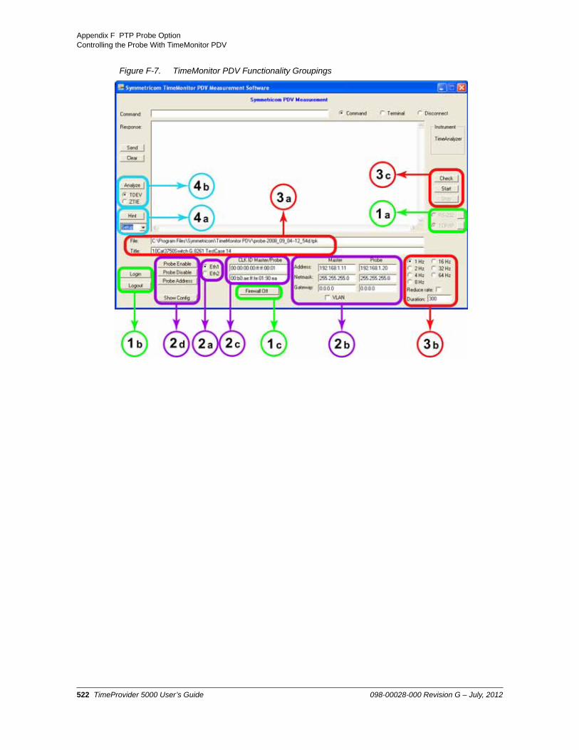
Appendix F PTP Probe OptionControlling the Probe With TimeMonitor PDV
Figure F-7. TimeMonitor PDV Functionality Groupings
522 TimeProvider 5000 User’s Guide 098-00028-000 Revision G – July, 2012

Appendix F PTP Probe OptionControlling the Probe With TimeMonitor PDV
Entering CLI Commands Manually with TimeMonitor PDV
The TP 5000 Probe can also be configured and operated with Command Line Interface (CLI) commands via a telnet session over TCP/IP. In addition to the GUI, the TimeMonitor PDV software provides two ways to manually enter CLI commands to the TP 5000 PTP Probe. In Command mode, commands can be entered in the Command field and sent to the TP 5000 probe by clicking the Send button.
Table F-3. Descriptions of TimeMonitor PDV Functionality
Function Description
1 Connect to TP 5000 probe.
a. Select RS-232 or TCP/IP (Disconnect mode).First time connection to a network requires connection via RS-232 to change IP address of MGMT port for TP 5000 Probe.
b. Login to TP 5000 Probe (Command mode).
c. Turn off Telnet firewall of TP 5000 Probe (Command mode, logged in).
2 Configure TimeMonitor and TP 5000 Probe address (Command mode).
a. Select Probe port.
b. Enter Grandmaster IP address and Probe IP address.
c. Enter Clock ID for Grandmaster.
d. Enable Probe for selected port and change Probe IP address per entry in 2b.
3 Measure packet delay between Grandmaster and TP 5000 Probe.
a. Enter file name and title for PDV measurement data.
b. Select sync rate for measurement and lease duration.
c. Start and Stop measurement (Command mode, logged in)
4 Analyze data file (Command or Disconnect mode)
a. Set the max number of samples for measurement plot.
b. Select type of measurement plot and start analysis.
098-00028-000 Revision G – July, 2012 TimeProvider 5000 User’s Guide 523

Appendix F PTP Probe OptionControlling the Probe With TimeMonitor PDV
In Terminal mode, the main display area of the TM PDV interface will function as a simplified terminal.
Complete commands, with proper syntax, must be used with either approach. The Tab completion feature for TP 5000 CLI commands is not available through the TimeMonitor PDV interface in either Terminal or Command mode.
See the TimeProvider 5000 User’s Guide for details about CLI commands and associated syntax.
Command ModeUse the following procedure to enter CLI commands manually with TimeMonitor PDV in Command mode:
1. Select the radio button for the Command mode.
2. Click the Login button to login to the TP 5000 probe.
3. Enter the Username and Password for the TP 5000 probe when prompted in the main display area of the screen.
4. In the Command field, enter the desired CLI command, as the following example image illustrates.
5. Click the Send button to send the command to the TP 5000 probe for execution. Any response will be shown in the main display area of the screen.
Terminal ModeTo display the IP address for the MGMT port on the TP 5000 Probe’s IMC card, enter the command “show ip status imc”. Use the following procedure to enter CLI commands manually with TimeMonitor PDV in Terminal mode:
1. Select the radio button for the Command mode.
The “Login:” prompt will appear in the main display. All other fields and buttons are greyed out, except for the Check, Start, and Clear buttons.
2. Enter the Username for the TP 5000 Probe at the prompt in the main display. Click the Enter button on user’s computer.
524 TimeProvider 5000 User’s Guide 098-00028-000 Revision G – July, 2012

Appendix F PTP Probe OptionProvisioning the Probe
3. Enter the Password for the TP 5000 Probe at the prompt in the main display. Click the Enter button on the user’s computer. The TP 5000 prompt will appear.
tp5000>
4. Enter the command at the TP 5000 prompt and click Enter.
Example:
Installing TimeMonitor
Refer to the TimeMonitor PDV User’s Guide for instructions on installing the TimeMonitor software suite.
Provisioning the Probe
Establish a Connection to the TP 5000 Probe
When using TimeMonitor PDV to provision the TP 5000, the first step is to connect the serial port of the computer to the Craft port on the IMC module.
The MGMT port on the IMC can also be used for the initial connection, assuming that the default IP address of the MGMT port does not conflict with the network. Use an Ethernet cable to connect the MGMT port of the TP 5000 to the network.
098-00028-000 Revision G – July, 2012 TimeProvider 5000 User’s Guide 525

Appendix F PTP Probe OptionProvisioning the Probe
See Chapter 2 of the TP 5000 User’s Guide for Installation details. See Chapter 4 of the TP 5000 User’s Guide for details about provisioning the TP 5000 using CLI commands.
Enable the Probe Option on the TP 5000
The probe option must be enabled with the Symmetricom authentication key in order to use the TP 5000 as a probe.
Use the show license command to check if the probe option has been enabled yet for the TP 5000. Use the set license command to enter the authentication key for
Example:To enable the probe option with an authentication key of “ABCDEFGHIJ1234567890KLMNOPQRST0987654321”:
tp5000> set license add
The TP 5000 will prompt for the license key:
License key: ABCDEFGHIJ1234567890KLMNOPQRST0987654321,
Note: The default IP address for the IMC MGMT port of the TP 5000 is:
IP Address: 192.168.0.100Gateway: 0.0.0.0Netmask: 255.255.255.0
Note: The unit’s default user name is “admin” and the default password is “symmadmin**”.
526 TimeProvider 5000 User’s Guide 098-00028-000 Revision G – July, 2012

Appendix F PTP Probe OptionProvisioning the Probe
Enable Port as a PTP Probe
The packet- service for a port must be set to ptp-probe to use that TP 5000 IOC port as a probe. The packet-service mode for IOC ports can be set independently, with one port operating in PTP grandmaster mode while the other port is configured for ptp-probe mode (IP addresses must be set to different subnets).
See Table F-4 for procedures.
.
Table F-4. Enable Port as PTP Probe Procedure
TimeMonitor PDV CLI Command
1. Click on the Command radio button to put TimeMonitor PDV into the proper mode for making Probe changes.
2. Click the Login button to login to the Probe. The Probe will prompt for Username and Password.
3. Select the desired Probe port using the radio buttons .
4. Click on the Probe Enable button.
Use the command :
set packet-service ioc1-1 ptp-probe
Example:To enable port 1 of IOC1 as a PTP probe
1. Login at the Admin or Config-user level.
2. Type set packet-service ioc1-1 ptp-probe and press Enter.
098-00028-000 Revision G – July, 2012 TimeProvider 5000 User’s Guide 527

Appendix F PTP Probe OptionProvisioning the Probe
Return Port to Grandmaster Mode
The packet- service for a port must be set to ptp-gm or ntp-server to change that TP 5000 IOC port out of PTP probe mode. See Table F-5.
Set the IP Address for Probe MGMT Port
The TP 5000 probe can be controlled through the Craft port or through the MGMT port of the IMC module. The MGMT port may be more effective for gathering data with the Probe because it can support higher data rates than the Craft port. The Craft port can only support SYNC Interval settings of 0.5 seconds (2 Hz) or slower.
The IP address for the MGMT port can only be set with CLI commands. It may be necessary to connect to the TP 5000 via the Craft port to set the IP address.
Table F-5. Return to Grandmaster Mode Procedure
TimeMonitor PDV CLI Command
1. Click on the Command radio button to put TimeMonitor PDV into the proper mode for making Probe changes.
2. Click the Login button to login to the Probe. The Probe will prompt for Username and Password.
3. Select the desired Probe port using the radio buttons (see Item 2).
4. Click on the Probe Disable button.
Use the command:
set packet-service ioc1-1 {ptp-gm | ntp-server | ptp-probe}
Example:To return port 1 of IOC1 to PTP grandmaster mode:
1. Login at the Admin or Config-user level.
2. Type set packet-service ioc1-1 ptp-gm and press Enter.
528 TimeProvider 5000 User’s Guide 098-00028-000 Revision G – July, 2012

Appendix F PTP Probe OptionProvisioning the Probe
Use the following CLI procedure in Table F-6 to configure the TimeProvider 5000 MGMT port IP parameters (Host Address, Subnet Mask, and Gateway Address). Use the dot-decimal notation format xxx.xxx.xxx.xxx to enter the address parameter. Use the TimeMonitor PDV procedure in Table F-6 to enter the IP address that TimeMonitor PDV will use to connect to the MGMT port..
Table F-6. Set MGMT Port IP Address Procedures
TimeMonitor PDV CLI Command
This procedure describes how to enter the IP address that TimeMonitor PDV will use to connect to the MGMT port.
1. Click on the Disconnect radio button to put TimeMonitor PDV into the proper mode for making MGMT port changes.
2. Click on the TCP/IP radio button.
3. Click on the button on the right side of “TCP/IP” to bring up the TCP/IP Settings dialog box.
4. Enter the IP Address that was set with CLI commands and the Port number.
5. Click the OK button to return to the main screen.
This procedure describes how to set the IP address for the MGMT port on the Probe.
Use the command:
set ip IMC address <addr_value> netmask <mask_value> gateway <gateway value>
Example:
For following settings on IMC:Address = 192.168.2.10Netmask = 255.255.255.0Gateway = 192.168.2.1
1. Login at the Admin or Config-user level.
2. Type set ip-mode imc static and press Enter.
3. Type set ip imc address 192.168.0.10 netmask 255.255.255.0 gateway 192.168.0.1 and press Enter.
4. Type set ip imc restart.
NOTE: The IMC card must be restarted to implement the IP address change
098-00028-000 Revision G – July, 2012 TimeProvider 5000 User’s Guide 529

Appendix F PTP Probe OptionProvisioning the Probe
Set Probe IP Address
The two Ethernet ports on the Probe IOC module can be configured as independent 1588 Probe ports or bonded to active/standby mode as a redundant pair. As with the TP 5000 when it is in Grandmaster mode, the redundant port uses the ETH1 port configuration. Therefore, the redundant ports share the same IP address and MAC address. The default condition for Ethernet ports on an IOC card is Port Redundancy OFF. However, Symmetricom does not recommend using the TP 5000 as a Probe with redundant ports.
The IOC Ethernet ports can only be configured with static IP addresses.
The TP 5000 allows VLAN over the redundant port as well as over independent ports. .
Enabling or disabling redundancy does not require the user to issue the “set IP restart” command.
See Table F-7 for procedures to set the Probe IP address
Note: The VLAN must first be configured with the “set vlan” command. VLAN can only be configured using CLI commands through a terminal.
530 TimeProvider 5000 User’s Guide 098-00028-000 Revision G – July, 2012

Appendix F PTP Probe OptionProvisioning the Probe
Table F-7. Set Probe IP Address Procedures
TimeMonitor PDV CLI Command
1. Click on the Command radio button to put TimeMonitor PDV into the proper mode for making Probe changes.
2. Click the Login button to login to the Probe. The Probe will prompt for Username and Password.
3. Select the desired Probe port using the radio buttons .
4. Enter the desired IP address, Netmask and Gateway for the selected Probe port
5. Enter the Clock ID for the selected Probe port. (optional). Use the show ptp-probe command to find the clock ID.
6. Click the Probe Address button to send the address information to the Probe.
7. Repeat steps 3 through 6 for the other port.
Use the command:
set ip IOC1-x address <addr_value> netmask <mask_value> gateway <gateway value>
Example - Independent Probe Ports:
1. Login at the admin or Config-user level.
2. Type set ip ioc1-1 address 192.168.1.10 netmask 255.255.255.0 gateway 192.168.2.1 and press Enter.
3. Type set ip ioc1-2 address 192.168.2.12 netmask 255.255.255.0 gateway 192.168.2.1 and press Enter.
4. Type set redundancy port ioc1 disable and press Enter.
Note: It is possible to set the TP 5000 for redundant probe ports, but this configuration is not recommended.
098-00028-000 Revision G – July, 2012 TimeProvider 5000 User’s Guide 531

Appendix F PTP Probe OptionProvisioning the Probe
Set Grandmaster PTP IP Address
To specify the Grandmaster to be used with the Probe the following parameters be provisioned. See Table F-8 for procedures to set the Grandmaster PTP IP address:
Grandmaster Clock ID
Grandmaster IP Address
Grandmaster VLAN Address (if any).
Table F-8. Set Grandmaster PTP IP Address Procedures
TimeMonitor PDV CLI Command
1. Click on the Command radio button to put TimeMonitor PDV into the proper mode for making Probe changes.
2. Click the Login button to login to the Probe, which will prompt for Username and Password.
3. Select desired Probe port using radio buttons.
4. Enter the IP address, Netmask and Gateway for the 1588 Master server for selected port.
5. If Master is part of a VLAN, click VLAN check box. Enter VLAN ID in the box that appears.
6. Enter the Clock ID for the Master server.
NOTE: For a TP 5000 Grandmaster, use the show ptp-status command to find clock ID .
7. Repeat steps 3 through 6 for the other port.
Use the command:
set ptp-probe IOC1-x active-probe gm-clock-id <clock-id> gm-ip <addr> [vlan-id <vlan>]
where x is the port number on the IOC
Example:
For following Grandmaster specs:Clock ID = 00:B0:AE:FF:FE:00:00:06IP address = 192.168.1.11VLAN ID = 35:
1. Login at the Admin or Config-user level.
2. Type set ptp-probe ioc1-1 active-probe gm-clock-id 00:B0:AE:FF:FE:00:00:06 gm-ip 192.168.1.11 vlan-id 35 and press Enter.
3. If there is no VLAN for the Grandmaster, type set ptp-probe ioc1-1 active-probe gm-clock-id 00:B0:AE:FF:FE:00:00:06 gm-ip 192.168.1.11 and press Enter.
532 TimeProvider 5000 User’s Guide 098-00028-000 Revision G – July, 2012

Appendix F PTP Probe OptionProvisioning the Probe
Set Synchronization Interval
The Interval parameter specifies the interval rate for Sync and Delay Requests. The range is 0.015625 seconds (64 Hz) to 128 seconds (0.0078125 Hz). The default value is 1 second (1 Hz) in the TimeMonitor PDV GUI. The default value is 0.015625 seconds (int-value = -6) if using the CLI command to set.
See Table F-9 for procedures to set the synchronization interval.
Set Lease Duration
The Duration parameter specifies the maximum lease duration for the Probe. The range is 10 to 1000 seconds. The default value is 300 seconds.
Table F-9. Set Synchronization Interval Procedures
TimeMonitor PDV CLI Command
1. Click on the Command radio button (see Item 1 in Figure F-6) to put TimeMonitor PDV into the proper mode for making Probe changes.
2. Click the Login button to login to the Probe. The Probe will prompt for Username and Password.
3. Click on the radio button that corresponds to the desired SYNC rate.
Use the command:
set ptp-probe IOC1-x active-probe interval <int-value>
where x is the port number on the IOC card.
The interval is 2z seconds, where z is the int-value specified in the command. The range for this value is -6 to 7. The default value is -6 if set using the CLI command.
Example:For an interval of -2 (0.25 seconds) on Port 1 of IOC1:
1. Login at the Admin or Config-user level.
2. Type set ptp-probe ioc1-1 active-probe interval -2 and press Enter.
098-00028-000 Revision G – July, 2012 TimeProvider 5000 User’s Guide 533

Appendix F PTP Probe OptionProvisioning the Probe
See Table F-10 for procedures to set the lease duration.
Table F-10. Set Lease Duration Procedures
TimeMonitor PDV CLI Command
1. Click on the Command radio button to put TimeMonitor PDV into the proper mode for making Probe changes.
2. Click the Login button to login to the Probe. The Probe will prompt for Username and Password.
3. In the Duration box (see Item 5), enter the desired value for the lease duration in seconds.
Use the command:
set ptp-probe IOC1-x active-probe duration <value>
where x is the port number on the IOC card
Example:
For a duration of 500 on Port 1 of IOC1:
1. Login at the Admin or Config-user level.
2. Type set ptp-probe ioc1-1 active-probe duration 500 and press Enter.
534 TimeProvider 5000 User’s Guide 098-00028-000 Revision G – July, 2012

Appendix F PTP Probe OptionOperating the Probe
Operating the Probe
Table F-11. Measurement Procedures
TimeMonitor PDV CLI Command
1. Click on the Command radio button to put TimeMonitor PDV into the proper mode for making Probe changes.
2. Click the Login button. The Probe will prompt for Username and Password.
3. Enter the desired file name and destination directory. The software will reuse a file name for new files and add on date and time to the file name if the file already exists. Also enter the desired title for file.
4. Select the radio button for the desired probe port.
5. Click on the Check button to preview PTP data before beginning measurement (optional).
The top of the main screen will display the message:
If the setup is configured correctly info like that shown Figure F-8 in will appear in display.
6. Click on the Start button to start the measurement process. The top of main screen will display the elapsed time of measurement
7. Click on the Stop button to stop measurement.
Symmetricom recommends that users ping from the probe to the grandmaster’s PTP IP address to verify the network connection before attempting to gather data. Improper network setup and configuration is the most common error encountered with the TP 5000 Probe.
Use the CLI command ping [imc | ioc1-1 | ioc1-2] [<vlan-id>] <IP address> to specify the IP address to ping and the Probe port from which to send the ping.
See Chapter 3, CLI Commands and SNMP for additional info.
Example:To ping the grandmaster at IP address 192.168.5.120, no VLAN from port IOC1-1 of the TP 5000 Probe:
Type ping ioc1-1 192.168.5.120 and press Enter.
____________________________
To begin the measurement:
show ptp-probe data ioc-[y]
where y is the port number.
Example:1. Login at the Admin or Config-user
level.
2. Type show ptp-probe data ioc-1 and press Enter to start the measurement process.
3. To stop the measurement process, press the Enter key again.
098-00028-000 Revision G – July, 2012 TimeProvider 5000 User’s Guide 535

Appendix F PTP Probe OptionOperating the Probe
Figure F-8. Typical Probe Response if Setup Is Correctly Configured
Figure F-9. Typical Probe Stats at End of Measurement
536 TimeProvider 5000 User’s Guide 098-00028-000 Revision G – July, 2012

Appendix F PTP Probe OptionProbe Data
Figure F-10. Anatomy of a Probe Message
Probe Data
Probe data includes the following information:
Message Type
Sequence Number
GM seconds
GM nanoseconds
Probe seconds
Probe nanoseconds
Correction field in nanoseconds
GM Clock ID
See Figure F-10 for a description of the anatomy of a probe message. See Table F-12 and Table F-13 for descriptions of message types and message parameters.
See below for a typical stream of Probe data.
098-00028-000 Revision G – July, 2012 TimeProvider 5000 User’s Guide 537

Appendix F PTP Probe OptionProbe Data
Example
f,00011,1229541029,099868364,1229541029,099881920,+0000000000,00a06efffe0084f2b,00011,1229541029,562553320,1229541029,562539700,+0000000000,00a06efffe0084f2f,00012,1229541030,099868364,1229541030,099881776,+0000000000,00a06efffe0084f2b,00012,1229541030,562553320,1229541030,562539700,+0000000000,00a06efffe0084f2f,00013,1229541031,099868364,1229541031,099881936,+0000000000,00a06efffe0084f2b,00013,1229541031,562553288,1229541031,562539700,+0000000000,00a06efffe0084f2f,00014,1229541032,099868364,1229541032,099881776,+0000000000,00a06efffe0084f2b,00014,1229541032,562553288,1229541032,562539700,+0000000000,00a06efffe0084f2
The Probe can return three different types of messages, as shown in Table F-12. Each message includes a single letter, m, f or b, to indicate the type of message.
.
Examples of informational messages are shown below.
Example
Table F-12. Message Types From The Probe
Letter Message Type
m Message, informational and errors
f Forward Sync Messages
b Backward Delay Messages
Table F-13. Sync and Delay Message Parameters
Parameter Description
Sequence Number The sequence number in the PTP packet
GM Seconds The integer part of the timestamp from the GrandMaster, with units of seconds
GM Nanoseconds The fractional part of the timestamp from the GrandMaster, with units of nanoseconds
Probe Seconds The integer part of the timestamp from the Probe, with units of seconds
Probe Nanoseconds The fractional part of the timestamp from the Probe with units of nanoseconds
Correction Field The value of the correction field, as received by the Probe
538 TimeProvider 5000 User’s Guide 098-00028-000 Revision G – July, 2012

Appendix F PTP Probe OptionAnalyzing Probe Data
M,,,,,,,INFO: ProbeIP 192.168.1.25,M,,,,,,,INFO: ProbeVLANID 35,M,,,,,,,INFO: ProbeClockID 00:B0:AE:FF:FE:01:31:69,M,,,,,,,INFO: MasterIP 192.168.1.11,M,,,,,,,INFO: MasterClockID 00:B0:AE:FF:FE:00:00:06,
A typical error messages may look like the following:
M,,,,,,,Error: Grandmaster is unreachable,
Saving Probe Data
Refer to the TimeMonitor PDV User’s Guide or Help for instructions on how to save Probe data with TimeMonitor PDVsoftware.
If operating the TP 5000 Probe with the CLI command “show ptp-probe data ioc1-x” , capture or copy the data displayed in the terminal emulator and save or paste the data into a “.txt” file. Before loading the data file to TimeMonitor Analyzer for analysis, the extension of the file needs to be changed from “.txt” to “.tpk”.
Analyzing Probe Data
Refer to the TimeMonitor PDV and TimeMonitor Analyzer User’s Guides for instructions on how to analyze Probe data with TimeMonitor software.
098-00028-000 Revision G – July, 2012 TimeProvider 5000 User’s Guide 539

Appendix F PTP Probe OptionAnalyzing Probe Data
540 TimeProvider 5000 User’s Guide 098-00028-000 Revision G – July, 2012
IndexIndex
Numerics10 MHz output 33, 53, 75
display status 185provisioning 185, 348specifications 457, 460
10MHz outputport 38, 347
1PPS output 33, 53, 75display port status 192port 38, 347provisioning 192, 348specifications 457, 459
2048kHz frame type 341, 345, 352250B-90 gas tube, installing 484-48 VDC power 42, 87-48 VDC power connections 84-48VDC status LED 90, 91, 166
Aacceptable master list 220, 221, 224, 382access level
changing 278displaying 276setting 258
accessoriesantenna 421, 484crimper kit 486–??GPS antenna part numbers 486GPS antenna transient eliminators 486–??L1 amplifier part number 487
accessory part numbers 416active FTP 255active IOC 156active IOC port, setting 156active port, setting 233, 234add
SNMP manager 241, 371SNMP trapuser 241SNMP user 241SNMP v2-community 241SNMP v3 user 373v2 community 372VLAN 264
add user 258add VLAN 261address
gateway configuration 273IP 52IP configuration 273subnet mask configuration 273
alarmgenerate messages 130severity codes 424
alarm configuration, setting 102alarm log, display 171alarm reporting delay 102alarm severity 361
alarm severity, changing 102, 361alarm status 51alarms
display status information 363enable/disable procedure 361provisioning 55
alarms, disable 361alarms, provisioning 361alias command 104altitude specifications
GPS antenna 485announce 319announce limit 204, 316announce limit, PTP 211antenna
descriptions 485GPS, connecting 495installing 493installing GPS 494L1 gains, minimum 484
antenna cableinstalling 495
antenna connections 83antenna kits 418antenna, GPS 72, 427ARP 297asset numbers 152assigning an alias 104authentication 179
show command 106authentication protocol
CBC-DES 266, 373HMAC-SHA-1-96 266, 373
authentication scheme 279authentication, RADIUS server 106authentication, remote 279auto negotiation, ethernet 298auto sync 108azimuth 136, 138
Bbacking up provisioning data 365backup configuration 112basic configuration 414
components required 414see also redundant configuration
baud rate 52, 117blank panels 414bonding 295
enable 233redundant port IP address 295show 233
brackets, rack mounting 62, 64bridging time 109
Ccable
appropriate cable-pulling devices 492
098-00028-000 Revision G – July, 2012 TimeProvider 5000 User’s Guide 541

IndexD—D
coaxial requirements 492coaxial signal loss 484coaxial, cutting 492delay, GPS 131, 133, 134, 138, 139, 200installing GPS antenna 494LMR-400 484
cables, GPS roof mount 419CAS 181, 187CAS frame type 342, 346, 353cautions defined 25CBC-DES 266, 373CCS 181, 187CCS frame type 342, 346, 353, 354CD 60changing password 277changing user access level 278chassis dimensions 448CLI 55, 384
conventions 95format 96keyboard usage 95user levels 97
CLI protocol 52client
acceptable master list 220status 220
client attributes, display 215client status, PTP node 222clients
acceptable master list 223monitor performance 383reboot 223, 224upgrade firmware 223, 224, 385
clients, max 210, 211clients, maximum 205clients, upgrade firmware 381clock 221clock description, PTP node 220, 221clock holdover specifications
quartz 465rubidium 465
clock ID 204, 319clock status table 247clock, set command 110clockid 213, 309coaxial cables. <Emphasis>See cablecommand
reboot 380set alarm config 362set configuration 365, 367set io 330set redundancy 297, 298, 531set tod-source 324, 325, 327, 329show alarm 363show alarm config 362show log alarm 379show log event 379show status 363
command history 143Command Line Interface (CLI) 94command log, display 171commands
password 196ping 197
reboot 230set alarm-config 102show alarm 97show alarm-config 98sync tod-source 254upgrade 255
commands, alphabetical listingdescription 97
communications portsIMC management Ethernet 52IMC serial 52, 272
community, v2 240, 242compatibility mask for IMC and IOC 152component part numbers 416configuration
backup 112see also non-redundant configurationbasic components required 414default 112factory 112gateway address 273IP address 273redundant 414subnet mask address 273
configuringserial port 35, 36
connecting the GPS antenna 495connections
DC power 89E1 input 40ethernet management port 69GPS 72GPS antenna 83grounding 86power 84PTP 72serial port 71synchronization & timing 71, 81, 82
connections, power 86connectons
ground 84connectors
GPS input 68IMC 51management ethernet 68requirements 492serial port 68
contacting Symmetricom 421, 484corrective actions 389craft port 52
connections 71CRC 147, 181, 187crc 341, 346, 352crimper kit
GPS antenna 486crimp-style connectors, requirements 492cutting coaxial cables, requirements 492
Ddata bits 52data length 117DC power connections 89default configuration, setting 112
542 TimeProvider 5000 User’s Guide 098-00028-000 Revision G – July, 2012

IndexE—G
default IP address 273defaults
general and communication parameters 466delay 319delay limit 204delay limit, maximum 206delay limit, PTP 211delay-limit 316delete
SNMP manager 241, 371SNMP trap user 241SNMP user 241SNMP v2-community 241SNMP v3 user 373v2 community 372
delete user 258, 259delete VLAN 263, 264, 265DHCP 273DHCP mode
enable 294DHCP mode, settiing 163DHCP state, display 158Diffserv Code Point 204Dimensions 63dimensions, chassis 448direct connect cable 36disable alarms 361disable VLAN 263Dither 204dither 206, 317dither, PTP 212documentation, related 26Domain 204domain 206, 317domain, PTP 211DSCP 206dscp 317DSCP, clients, maximum number 204DSCP, PTP 212dscp-state 317duplex 389duration, lease 208, 213dynamic lease duration, unicast 208dynamic negotiation, unicast 207
EE1 33
input connections 40input specifications 451output ports 37output specifications 457, 460outputs 345programmable output ports 37provisioning input 149provisioning outputs 183provisioning programmable inputs 331provisioning programmable outputs 340reference 329, 330
EIA-232 94EIA-232 connector pin assignments 37EIA-232 serial connection 33EIA-232, see serial portelectrical specifications
GPS antenna 485GPS L1 inline amplifier 487
electromagnetic compatibility (EMC) 59electrostatic discharge (ESD) 60elevation 136, 138email address, Symmetricom 421, 484enable alarms 361enable VLAN 263environmental specifications 448
GPS antenna 485equipment, installation 59ESD 388Ethernet 35ethernet auto negotiation 298, 389Ethernet Management 33ethernet management port
connections 69Ethernet MGMT port
LED 90, 91, 92, 166ethernet port 52ethernet port speed 120ethernet status 51event log, display 171events, display current 123
Ffactory default 367factory defaults 112fax number, Symmetricom 421, 484firewall 273, 274, 391
FTP 129ICMP 129SFTP 129SNMP 129SSH 129TELNET 129
firewall defaults 466firmware image, display 145firmware image, set 146firmware versions 152firmware, upgrade 255, 256, 381, 391, 405, 412, 413flow control 52, 117Forced 147format, CLI 96FPGA 429FPGA versions for IMC and IOC 152frame ground connections 42frame type, 2048kHz 335, 337, 341, 343, 345, 352frame type, CAS 336, 337, 342, 344, 346, 353frame type, CCS 335, 337, 342, 343, 346, 353, 354frametype 182, 188Framing 147FTP 255, 385, 391FTP, active 255fuse, branch over-current protection 58, 59fuse, internal 400fuses, not field-replaceable 400
GG 37, 38, 40G.703/13 37, 38, 40G.703/9 37, 38, 40
098-00028-000 Revision G – July, 2012 TimeProvider 5000 User’s Guide 543

IndexH—I
gain, GPS antenna 486Gateway 294gateway address 293gateway address configuration 273gateway, IP addresses 158gateway, provisioning 160generate command 130generation, 10MHz 185generation, 1PPS 192GNSS 41, 426GPS 41, 326
antenna connection 51antenna kits 418antenna part numbers 418cable delay, set 131, 133, 134, 138, 139, 200connections 72display parameters 136input connectors 68input signal 33L1 amplifier specifications 487lightning arrestors 84mask, set 133, 138provisioning reference 323set parameters 138signal status 51status LED 90, 166Time of Day source 253
gps 327GPS antenna 427
accessories 486caution near high voltage lines 490connecting 495crimper kit 486gain 486installation 493
tools and materials 492installation recommendations 490installing 493installing cable 495L1 amplifier 487low noise amplifier 484with internal LNA 484
GPS input requirements 450Grandmaster 384ground
frame connections 42, 85ground connections 42grounding connections 86grounding terminal stud 84, 85
Hhandling modules 67hardware status, display 141hardware versions for IOC and IMC 152heat dissipation 58history,command 143HMAC-SHA-1-96 266, 373holdover specification
quartz 465rubidium 465
holdover status 51holdover, bridging time 109holes, mounting 63
host address setup 293hostname, display 144hostname, set 144Humidity 59
II 43, 68, 347I/O module 33I/O module, port configuration 155I/O ports 33I/O, display config & status 157image, firmware 145IMC
communications ports 52connectors 51LED descriptions 90, 166LEDs 51reboot 230troubleshooting with LEDs 396, 398upgrade firmware 255, 256
independent ports 295, 298input 335, 336, 337
display reference 235E1 40E1 reference 329, 330E1 signal 149provisioning reference 323
input signalGPS 33
input signal specifications 450inputs
display 147inputs, programmable 331installation
completeness checklist, antenna 496preparing site 488transient eliminators 494
installation check list 89installation kit 86installing 62
GPS antenna cable 495installing the GPS antenna 493internet address, Symmetricom 421, 484intra-system network classes 151inventory, set 154IO 335, 336, 337, 341, 342, 343IOC 43
active mode 295alarm LED 91, 166clock status table 247LED descriptions 90, 166LEDs 51quartz clock 417reboot 230redundant ports 233rubidium clock 417standby mode 295switchover 156troubleshooting with LEDs 392upgrade firmware 255
IOC, active & standby states 156IP address
default 273
544 TimeProvider 5000 User’s Guide 098-00028-000 Revision G – July, 2012

IndexK—P
IP address configuration 273IP addresses
provisioning 160IP addresses, display 158IP, static mode 294
Kkey for SNMP option 179
LLAN port specifications 450Latitude 138latitude 138, 326leapseconds, accumulated 110leapseconds, pending 110lease 318lease duration, dynamic 208lease duration, max 213LED
Ethernet MGMT port 90, 91, 92, 166system health 90, 166
LED descriptions 90, 166LED status, display 164LEDs
IMC module 51IOC module 51
LEDs, troubleshooting IMC 396, 398LEDs, troubleshooting IOC 392LEDs, troubleshooting with 389lightning arrestors, GPS 84LNA. See GPS antennalocal login 279log size, display 173log size, provisioning 173logout 174logs, display 171logs, displaying 379Longitude 138longitude 138, 326low noise amplifier. See GPS antenna
Mmanagement ethernet connector 68Management Information Base (MIB) 266manager, SNMP 371Mask 294mask address 293mask, GPS 133, 138materials and tools
GPS antenna installation 492max clients, PTP 210, 211max-client 316mechanical specifications 448
GPS antenna 485GPS L1 inline amplifier 487
messages, system notification 426MGMT port 367
pin assignmetns 70MGMT port specifications 450modify password 196, 258, 259
module LED descriptions 90, 166module slots
vacant 414module, I/O 33modules
handling 67removing 68
mountingbracket assembly 486GPS antenna specifications 485
mounting hole placements 63mounting in rack 64
Nnegotiate 318negotiation
Ethernet auto 298negotiation, unicast dynamic 207, 213netmask, IP addresses 158netmask, provisioning 160notes defined 25NTP 322NTP commands 177, 178, 195NTP server 30, 40, 321, 322NTP server parameters 476NULL_MANAGEMENT messages 220, 222
OOID 369option, SNMP 370options, display 179options, enabling 179ordering
GPS antenna accessories 486–??Output 185output 341, 342, 343, 344, 345, 346, 352, 353
10MHz 53, 751PPS 53, 75ptp connections 40
output port10 MHz 38, 1851PPS 1921PPSMHz 38
output portsdisplay states 180provisioning 180
output signal specifications 457, 459, 460outputs
E1 345programmable 340
Ppanels
blank 414parity 52, 117part numbers
antennas 485component and accessories 416crimper kit, GPS antenna 486GPS antenna 418
098-00028-000 Revision G – July, 2012 TimeProvider 5000 User’s Guide 545

IndexQ—R
part numbers, component 416part numbers, TP5000 414passive FTP 255, 391password recovery 259password, changing 277password, modify 196passwords 275, 277, 278PASV 255, 391pin assignments
serial port 71pin assignments, EIA-232 37pin assignments, MGMT Ethernet connector 70ping 197port
IMC ethernet 52MGMT 52
port bonding 295show 233
port, EIA-232 52ports, I/O 33ports, independent 295ports, redundant 295power
GPS antenna specifications 485power connections 42, 84, 86
DC 89power connections, testing 88power specifications 449, 465power, status 51PQL 147pql 335preparing antenna site installation 488Priority 147priority 206, 211, 335, 336, 337, 338Priority 1 211priority 1, PTP 204Priority 2 211priority 2, PTP 204priority-1 317priority-2 317product overview, TimeCreator 1000 29programmable inputs
E1 331programmable outputs
E1 340protocol
CLI 52SNMP 52
provisioningalarms 55
PTPannounce limit 211common commands 314common parameter descriptions 315, 317connections 72delay limit 211dither 212domain 211DSCP 212dynamic negotiation 213lease-duration 213max-clients 210, 211priority-1 211priority-2 211
provisioning 304sync limit 211timescale 210unicast dynamic commands 315unicast dynamic parameter descriptions 318unicast static commands 315unicast static parameter descriptions 318, 319
ptp 381PTP configuration, display 217ptp node 223
acceptable master list 220, 221client status 220, 222clock description 220, 221NULL_MANAGEMENT messages 222
ptp output connection 40PTP output specifcations 457, 459ptp status, display 229purpose of this guide 22
Qquartz clock holdover specification 465quartz IOC module 417
Rrack mounting 64rack mounting brackets 62, 64rack space 58RADIUS 279, 467RADIUS server authentication 106RADIUS server, configuring 279RADIUS server, provisioning 279reboot 381, 385reboot command 230, 380reboot, clients 224recommendations defined 25redundancy 43
disabling 298redundancy, show 233redundant configuration 414
components required 414see also basic configuration
redundant operation 84redundant port IP address 530redundant port MAC address 530redundant ports 297
IP address 295, 297MAC address 295, 297
redundant ports, provisioning 295ref 324, 325, 327, 329reference
display 235override criteria 236override priority 236provisioning
GPS 323provisioning E1 input 329, 330synchronize 254
related documentation 26relative humidity
GPS antenna 485remote syslog, provisioning 238remote syslog,display 238
546 TimeProvider 5000 User’s Guide 098-00028-000 Revision G – July, 2012

IndexS—S
removing modules 68repairs 400requirements, connectors 492return material authorization number (RMA) 420returning equipment 419rubidium clock holdover specification 465rubidium IOC module 417
Ssales department, Symmetricom 421, 484satellite azimuth 136, 138satellite elevation 136, 138satellites
azimuths and elevations 484gain required 484
security levels, described 274security log, display 171serial connection
EIA-232 33serial numbers for IMC and IOC 152serial port 52
baud rate 117communication 272configuring 35, 36connections 71connector 68data length 117parity 117pin assignments 71stop bits 117
serial port specifications 450service
technical assistance 58session timeout, setting 252set alarm config command 362set commands
alarm-config 102auto-sync 108bridge-time 109clock 110configuration 112firewall 129GPS 138hostname 144image 146intra-system 151inventory 154io 155ioc-state 156IP 160ip-mode 163log-size 173option 179output 180output-10m 185output-pps 192ptp--node 223redundancy 233remote-syslog 238snmp 241timeout 252tod-source 253user 258
vlan 261set configuration command 365, 367set io command 330set redundancy command 297, 298, 531set tod-source command 324, 325, 327, 329severity codes, alarms 424severity, alarm 361SFP 40, 389, 418SFP transceivers 73, 515SFTP 255, 391show alarm command 363show alarm config command 362show commands
alarm 97alarm-config 98auto-sync 108bridge-time 109clock 110eia-232 117ethernet status 120event 97, 123firewall 129GPS 136hardware-status 141hostname 144image 145input 147intra-system 151inventory 152io 157ioc-state 156IP 158led 164log 171log-size 173option 179output 180output 1pps 192output-10m 185ptp-client 215ptp-confi 217ptp-node 220ptp-status 229redundancy 233ref 235remote-syslog 238snmp 239status 245timeout 252tod-source 253user 258
show log alarm command 379show log event command 379show status command 363signal strength, antenna gains 484Small Form-factor Pluggable 33SNMP 266, 384, 467
display information 239, 241enabling option 370manager 239, 241, 242, 371security level 242state 239, 240, 241trap user 239, 240, 241, 242trap version 239, 240, 241, 243
098-00028-000 Revision G – July, 2012 TimeProvider 5000 User’s Guide 547

IndexT—U
traps 385user 239, 241, 373v2 community 239, 240, 241, 242, 372
SNMP option 179SNMP protocol 52SNMPv2c 266, 369, 373, 384SNMPv3 266, 369, 373, 384soldered connections 495specifications
environmental 448GPS antenna 485GPS L1 amplifier 487input signals 450LAN port 450mechanical 448output signals 457, 459, 460power 449, 465quartz clock 465rubidium clock 465serial port 450transient eliminators 486
SSH 255, 274SSM 181, 187ssm 335, 336, 337, 338, 341, 342, 343, 344, 346, 352standby IOC 156standby IOC, setting 156State 147state 316static IP address
gateway setup 293host setup 293mask setup 293
static IP mode 294static mode, setting 163status
alarm 51ethernet 51, 120GPS LED 90, 166GPS signal 51holdover 51power 51
status, client 384status, display 245stop bits 52, 117structure of this guide 23subnet mask address configuration 273Switchover 156switchover, auto 297switchover, manual 297sychronization limit 204sychronize
time 254Symmetricom Global Services (SGS) 58sync interval 318, 319sync limit, PTP 211synchornize
phase 254synchronization limit, maximum 206synchronize
ToD source 254sync-limit 316syslog messages 425System 426system
reboot 230system date & time, setting 360system health LED 90, 166system messages 389system notification messages 426system reference, display 235system status 364
Ttechnical assistance 58temperature 59
GPS antenna specifications 485time
current IMC 110current IOC 110setting manually 360
Time of Daydisplay source 253set source 253setting 360
Time-of-Day Source, default 466timeout, display 252timeout, setting 252Timescale 204timescale 316timescale, PTP 210ToD source 360tools and materials
antenna installation 492tools, installation 59transceivers, SFP 73, 515transient eliminators 486
GPS antenna accessories 486installing 494L1 signal loss 484specifications 486
trap user, SNMP 240trap version, provisioning 372trap version, SNMP 240traps, SNMP 385troubleshooting symptoms 389troubleshooting with system messages 426
Uunicast
Announce message interval 217announce message interval 217clock ID 204delay interval 204, 217delay message interval 217domain 217DSCP 217dynamic negotiation 204lease duration 204lease interval 217negotiation 217priority 1 217priority 2 217Sync message interval 217sync message interval 204, 217VLAN ID 204, 217VLAN priority 217
548 TimeProvider 5000 User’s Guide 098-00028-000 Revision G – July, 2012

IndexV—W
unicast dynamic 308lease duration 208negotiation 207
unicast static 309upgrade client firmware 224, 381, 385upgrade firmware 255, 256, 391, 405, 412, 413user access level 258user access level, changing 278user access levels
displaying 276user access list, managing 274user list, display 258user password, changing 277user, delete 259user, modify password 259UTI 33
Vv2 community 242
v2 community, add or delete 372v2 trap, provisioning 372v2, SNMP 266v3 trap, provisioning 372v3, SNMP 266vacant module slots 414VLAN 390
add 264commands 300delete 263, 264, 265enable 263ID 213, 309, 318, 319modify 262, 263provisioning 261, 300
Wwarm 392warnings defined 25web address 26
098-00028-000 Revision G – July, 2012 TimeProvider 5000 User’s Guide 549

IndexW—W
550 TimeProvider 5000 User’s Guide 098-00028-000 Revision G – July, 2012