Multifunctional telecommunication tower and entertainment centre construction
Upload
nguyendangCategory
view
234download
3
Tower Construction, Tower Standards and Failure Prevention
Thomas B. Silliman, PEPresident and CEO
Electronics Research, Inc.
ANSI/TIAANSI/TIA--1019 (DRAFT)1019 (DRAFT) Structural Standards for Installation, AlterationStructural Standards for Installation, Alteration and Maintenance of Communication Towers, and Maintenance of Communication Towers,
Antennas and Antenna Supporting StructuresAntennas and Antenna Supporting Structures

Historical Development of Standards
• SEI/ASCE 37 – 02 Design Loads on Structures During Construction: Approved in 2001
• TIA-1019 Gin Pole Standard was approved January 9, 2004.
• TIA-222-G– Revision of TIA/EIA-222-F– Standard for design of communication structures – Aug. 2005
• TIA-1019- Construction Standard scheduled for approval in the Fall of 2009– Includes the Gin Pole Standard
ANSI/TIAANSI/TIA--222222--GG August 2005August 2005
• This standard does not account for construction equipment loading, removal of members, uneven guy wire forces, or loading on the tower in its unfinished state.
Structural Standard for Antenna Supporting Structures and Antennas
The New Standard will incorporate the existing gin pole standard

ANSI/TIA-1019-2004 Gin Pole Standard July 9, 2004

What is a Gin Pole
• It is a device unique to the Telecommunications and Broadcast Industries used to raise successive sections of tower steel and equipment into position.
• This temporary device allows headroom above the highest fixed point of a tower or structure to place equipment or materials.

Gin Pole in Use

Development of Gin Pole Standard
• Standard developed mostly by ERI after a conversation between Ernie Jones and me
• I asked for safe gin poles for our tower construction business
• Ernie indicated that it was impossible to guarantee that a gin pole could be properly designed because there was no design standard for gin pole design
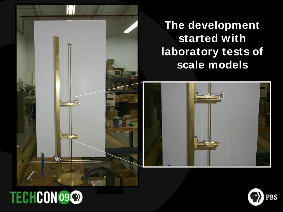
The development started with
laboratory tests of scale models

Bridle Slings
Fall Guide
Ruler for Reference
This was followed by full scale tests

Testing to Failure
TR 14.7 Gin Pole Sub-Committee Concerns
• Continual construction failures and the impact those failures had to our industry and to personnel.
• The additional loading construction equipment has on the structure and the methods used while applying those loads.
• The need for a standard combining tower construction concerns with the current gin pole standard and specific construction loading.

TIA-1019 (Draft)
The current plan:Adapt TIA-1019 in 2009

Advantages for the Broadcaster
• Adherence to Standard could reduce insurance costs
• Adherence to standard will not only make construction safer but also will reduce risk of broadcast platform failure
• Makes construction procedures consistent– If contractor doesn’t use standard, broadcaster is assuming more risk

Scope and Objective of New Construction Standard
• Structural Loading effects on the Structure due to Construction Equipment loading will be known.– Cranes – Gin Poles– Lifting Blocks – Attached Rigging
• Develop a standard to allow an engineered approach to complete work safely throughout the construction process.

• 1.0 General• 2.0 Construction Considerations• 3.0 Gin Pole Operation and Use• 4.0 Supporting Structure Loading During Construction• 5.0 Gin Pole Analysis and Design• 6.0 Gin Pole Construction• Annex A Procurement and User Guidelines• Annex B Gin Pole Engineering Design• Annex C Evaluation of Existing Gin Poles• Annex D Rigging Plans• Annex E Wire Rope End Connections• Annex F Evaluation of a Communication Tower Site• Annex G Referenced Standards

General
• Definitions• Symbols and notations

Definitions• Competent Rigger: a person knowledgeable and experienced with the
procedures and equipment common to the Communication Structures Industry, and trained to identify hazards with authorization to take prompt corrective measures.
• Qualified Person: a person knowledgeable, experienced, trained and capable of developing rigging plans and that has successfully demonstrated the ability to solve, resolve and coordinate construction related to the Communication Structures Industry.
• Qualified Engineer: a professional engineer knowledgeable and experienced in the Communication Structures Industry.

Competent Rigger
• Must have a minimum of 5 years construction experience in Broadcast or Telecom structures.
• Training in rigging practices and in the proper use of rigging equipment is required. This can be obtained from the following sources:– Industry related rigging manuals– Industry related rigging handbooks– Applicable video training programs– Manufacturers training presentations
• Should be a Competent Climber and if not, have the knowledge of the Competent Climber requirements.

Qualified Person
• Have met all the qualifications of a Competent Rigger.
• Have a basic understanding of sections 1,2,3, 4.3 and 4.5 of TIA/1019.
• Have a basic understanding of Appendix A, C, D, E and F of TIA/1019.
• Be able to communicate with the Competent Rigger and the Qualified Engineer using industry accepted terminology.

Qualified Engineer
• Must be a licensed professional engineer.
• Should be knowledgeable and competent regarding the EIA/TIA- 222F, TIA-222-G and TIA-1019 standards.
• Should be knowledgeable in the terminology and industry practices used in rigging applications for the construction industry.
• Be able to communicate with the Competent Rigger and the Qualified Person using industry accepted terminology.
Rigging Plan Requirements
• A rigging plan shall consider the following:
– Operational and Non-Operational loads.
– Construction equipment.
– Support structure and construction equipment strength.
– Construction sequence
– Load testing
– Field monitoring
Rigging Plan Work Description
• Class 1– Removal or addition of antennas, mounts, platforms, etc. that are
light in comparison to the overall supporting structure and do not require the use of a gin pole or a gin pole not rated higher than Class A.
• Class 2– Rigging plans utilizing pre-approved installation methods.
• Class 3– Custom or infrequent installation methods, removal of structural
members, special engineered lifts, and unique situations

Rigging Plan Classifications
Class DefinitionMinimum Level
of Responsibility
I
Removal or addition of antennas, mounts, platforms, etc. that are light in comparison to the overall supporting structure and do not require the use of a gin pole or a gin pole not rated higher than Class A.
Competent Rigger
II Rigging plans utilizing pre-approved installation methods. Qualified Person
IIICustom or infrequent installation methods, removal of structural members, special engineered lifts, and unique situations
Qualified Person with Qualified
Engineer

Construction Considerations
• Scope• Construction equipment• Lifting devices• Effects of gin pole jumping and lifting• Hoist• Temporary supports• Rigging components• Dismantling/Modification of existing antennas or structures• Rigging plan requirements• Load testing and verification• Monitoring During Lifting Operations• Safety climb facilities site inspection

Climbing Facilities
• Maintain the climbing pathway clear of obstructions• Consideration shall be given when adding mounts and antennas• All damaged climbing facilities must be evaluated and shall be
repaired, replaced or removed as required. • When obstruction of a climbing facility is unavoidable signage
shall be provided in accordance with TIA-222-G.
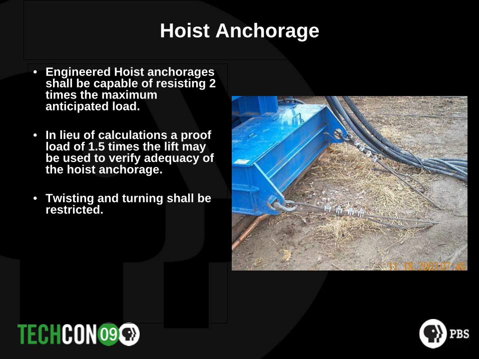
Hoist Anchorage
• Engineered Hoist anchorages shall be capable of resisting 2 times the maximum anticipated load.
• In lieu of calculations a proof load of 1.5 times the lift may be used to verify adequacy of the hoist anchorage.
• Twisting and turning shall be restricted.

Types of Hoist Anchorage
Hoist On Trailer Anchored with Vehicle
(Will Require Load Testing)
Hoist Anchored to a Dead-Man Anchor
Hoist Anchored to a Foundation Top
Load Line
Load Line
Load Line

Hoist Load Tests
• If slip resistance is counted on for restraint a load test is required.
• Load test to 1.5 times the anticipated load.
Hoist
Load Test Weight

Supporting Structural Loading During Construction
• Scope • Design standards• Structural loads• Load combinations• Wind loadings

Tower Leg Capacity• Example
• Tension Capacity is 50 Kips
• Compression capacity 100 Kips
• (50 / 100 ) x 100% = 50%
• Leg tension capacity is 50% of the legs compression capacity.

Guy Wire Installation
• Guy wires are typically installed sequentially from the bottom to the top.
• All forces on members during the pulling up of guys shall be considered.
• When pulling up wires for a specific level, equal or near equal forces shall be applied.
• Vertical alignment shall be maintained at a ratio of 1/120 per fixed guy level.

Temporaries
Rigging plan will specify where temporary guys are needed during construction

Guy Anchor Temporary Support
• Slip resistance of an object (Dozer) can be calculated by using a coefficient of friction of 0.20.
• If slip resistance of the object is known then it can be used.
• Factor of Safety of 2 should be used for the allowable resistance.

Non-Slip End Connections
• End Connections that when properly installed have not had a history of slippage problems
Preformed End
Swage End
Turn Back End Wedge Socket End

Slippage Connections• When frictional clamping devices are used that may slip during
construction, the forces on the structure due to potential effects from slippage or cable release must be considered.
• The structure shall be analyzed for this potential slippage.
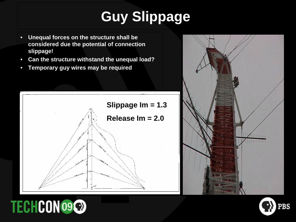
Guy Slippage• Unequal forces on the structure shall be
considered due the potential of connection slippage!
• Can the structure withstand the unequal load?• Temporary guy wires may be required
Slippage Im = 1.3
Release Im = 2.0

Temporary Backup System• The backup system shall be of non-slip wire rope termination arranged
to limit slippage to ½ face width of tower, but not less than 12 inches or more than 36 inches.
Chicago Grip
Attached Preform
Tension MeterCome-Along
Turnbuckle to be AttachedCable Clamped Backup
Guy Anchor

Temporary Support Guy Replacement
• Temporary guy wires are required when replacing existing guys, except when a engineering analysis indicates otherwise.
• The B.S. of the temporary guy wire assembly shall not be less than 50% of the wire being replaced unless an analysis indicates otherwise.

Block Loading
• Block forces transmitted to the structure must be properly evaluated and accounted for.

Working on Existing Antennas or Structures
• Weights may be unknown.
• Structural condition may be questionable.
• Special inspection will be necessary.
• Verify weight and geometry within plus or minus 5%.
• Special lifting procedures may be required.

Lifting Existing Loads from Structures
• Unless the load weight is confirmed by accurate documentation or by calculation, the weight shall be field verified prior to making the lift.
• Weight verification may be accomplished by loosening fasteners or by providing longer fasteners to allow movement while controlling the load. – Using a load measuring device

Temporary Member Supports• Consult an engineer to complete an analysis.• A temporary brace equal in strength shall be installed prior to
removable, unless the engineering analysis indicates other options are feasible.
• There shall be a documented procedure for the process as outlined in the standard.
EXISTINGHORIZONTALSTO BE REPLACED
EXISTING TENSION RODS
EXISTING TENSION RODSREF. TOWER LEG
TEMPORARYSTRUT TYP.
INSTALL TEMPORARY STRUTAS CLOSE AS POSSIBLETO HORIZONTAL TYP.
EXISTING HORIZONTALSTO BE REPLACED
EXISTING TENSION RODS
EXISTING HORIZONTALS
INSTALL TEMPORARY FRAMEASSEMBLY AS CLOSE AS
POSSIBLE TO HORIZONTAL
TEMPORARYFRAME
ASSEMBLY
REF. TOWER LEG
EXISTINGTENSION RODSTO BE REPLACED

Gin Pole Operation and Use
• Scope• Gin pole • Lifting personnel• Gin pole inspections• Load chart for gin poles in a vertical position• Tilted gin poles• Special engineering lifts

Classification Of Gin Pole
Class A Gin Pole – <1000 lbs Lift CapacityClass B Gin Pole – 1000 lbs to <3000 lbs CapacityClass C Gin Pole – 3000 lbs to <10,000Lift CapacityClass D Gin Pole – above 10,000 lbs Lift Capacity

Monitoring a Lift
• Load Testing
• Questionable tower movement
• Special Engineered Lift
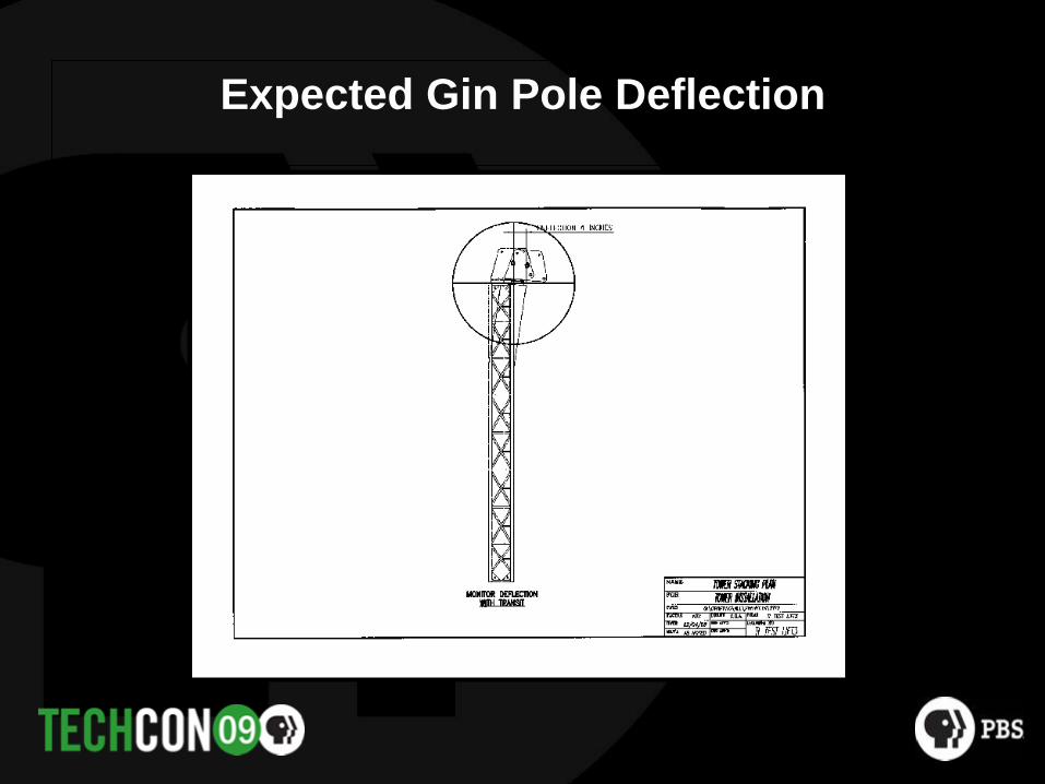
Expected Gin Pole Deflection

Tip Deflection Helps Verify Lifted Load is Within Lift Parameters
Hface
Hface distance measured at Bridle verifies a lift is within charted load line angles

Degree to Distance Conversion Chart
Hface

Changing Degrees to Inches
Hface

Monitoring During Lifts
• During lifting operations, deflection of the tip of the gin pole and/or the supporting structure shall be monitored to ensure deflections are within the anticipated magnitudes.
• Without verification by analysis keep deflections with the following limitations:– Guyed Tower deflection limit is ½ of the tower face width.– Self Supporting tower deflection limit off 1% of structure height.

Special Engineering Lift
1. It is the intent of this standard for lifts to be within the ratings allowed in the “Load Chart” as defined by this standard. (Load Charts are based on minimum 3 degree load line angles)
2. Any lifts to be allowed on a special basis, which is outside of the standard “Load Chart”, shall only be allowed at the direction of a qualified engineer.
3. Special monitoring and measuring conditions, as specified by the engineer, shall be provided and used in the field during all “Special Engineered Lifts”.

Requirements for Special Engineered Lifts
1. Engineering Evaluation is Needed to Determine that Gin Pole Lift Capacity has all Required Factors of Safety.
2. Load Line Angles Cannot be Considered Less than 1 Degree.
3. Tip Deflection of the Pole and the Location of Load Line During Lift Must be Monitored in the Field.

“Special Engineered Lifts” can be based on lifting with load Line angles Less than 3 Degrees
Special LiftProvisionsRequired
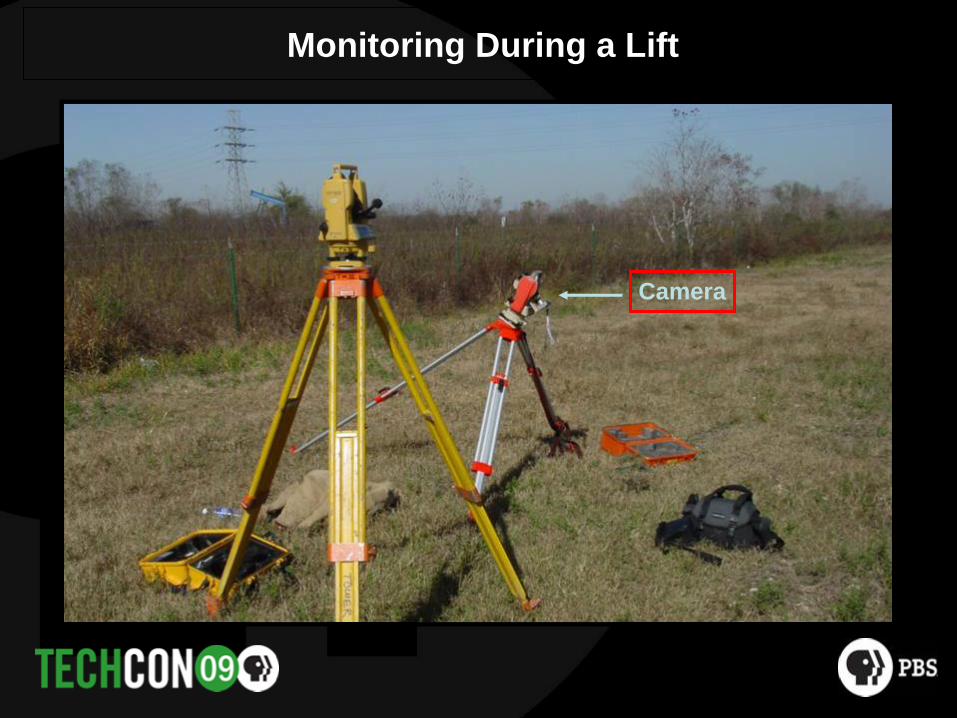
Monitoring During a Lift
Camera

Shot Thru Transit

No-Load Condition
Cross hairs on the edge of the leg

Load off the Ground with Minimum Tag
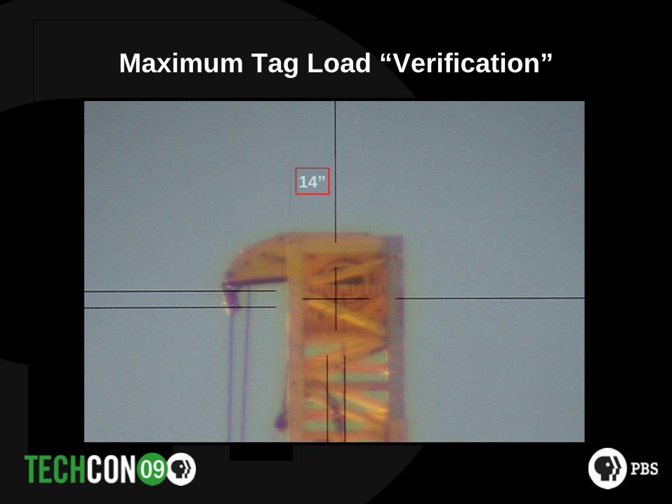
Maximum Tag Load “Verification”
14”

Regular Tag Situation

Gin Pole Back to Original Unloaded Position

Bridle Slings
• Controls the stability and keeps the pole vertical.
• Is the upper most attachment point, usually where the cantilever distance starts.
• Should be flat to the horizontal.
• Should be a minimum of 45 degrees

Basket Slings

Straight and Trolley Tag Systems

Tag Line Angle to Ground
Tag Line Angle

Controlling the Load Line

Vertical Gin Pole
Load Chart
Notes Added to Chart

Operational Conditions• Conditions in which the
structure is subject to additional loading during a lifting sequence.
• Wind load• Bridle forces• Basket forces• Block loading• Hoist anchorage

Operational and Non-Operational Conditions
• Operational– Loading conditions of a structure during the actual lifting
sequence.– Typically governs the strength requirements for lifting devices
and their associated rigging. – (gin pole and attached rigging equipment loads)
• Non-Operational– Loads on a structure when lifting is not performed.– Typically govern the strength requirements for the structure
under construction.– (wind load conditions based on construction duration factor)

Operational and Non-Operational Wind Speed
• Operational Wind Speed– A uniform effective 30 mph 3-sec gust wind speed.
• Non-Operational Wind Speed– Varies from 45 mph to 90 mph based on the construction duration period.
30 mph Wind
45 to 90 mph Wind
Non-OperationalOperational

Non-Operational Wind Loads During Construction
Construction Period Minimum FactorContinuous work period 0.50 (0.5 x 90 mph = 45 mph)
Less than 24 hours 0.60 (54 mph)(overnight conditions)
24 hours to 1 week 0.67 (60 mph)
1 week to 6 weeks 0.75 (67.5 mph)
6 weeks to 6 months 0.80 (72.0 mph)
Greater than 6 months 1.00 (90 mph)
Wind Speeds are 3-Second Peak Gust

Tilted Gin Pole Use to be Covered

Inspection Criteria
• A competent Rigger shall complete a visual inspection after assembly
• A Qualified Person shall perform a detailed inspection yearly• Allowable deformation and condition of members shall be
within tolerances noted in this standard• Wear shall be checked in bridle and basket attachment
points• Rooster head shall be checked for wear• Rigging hardware shall be checked for proper condition

Repairs and Modifications
• Repairs made with same or similar materials.
• Qualified Engineers shall be consulted for repairs.
• Qualified welders and Fabricators shall be used when making repairs.
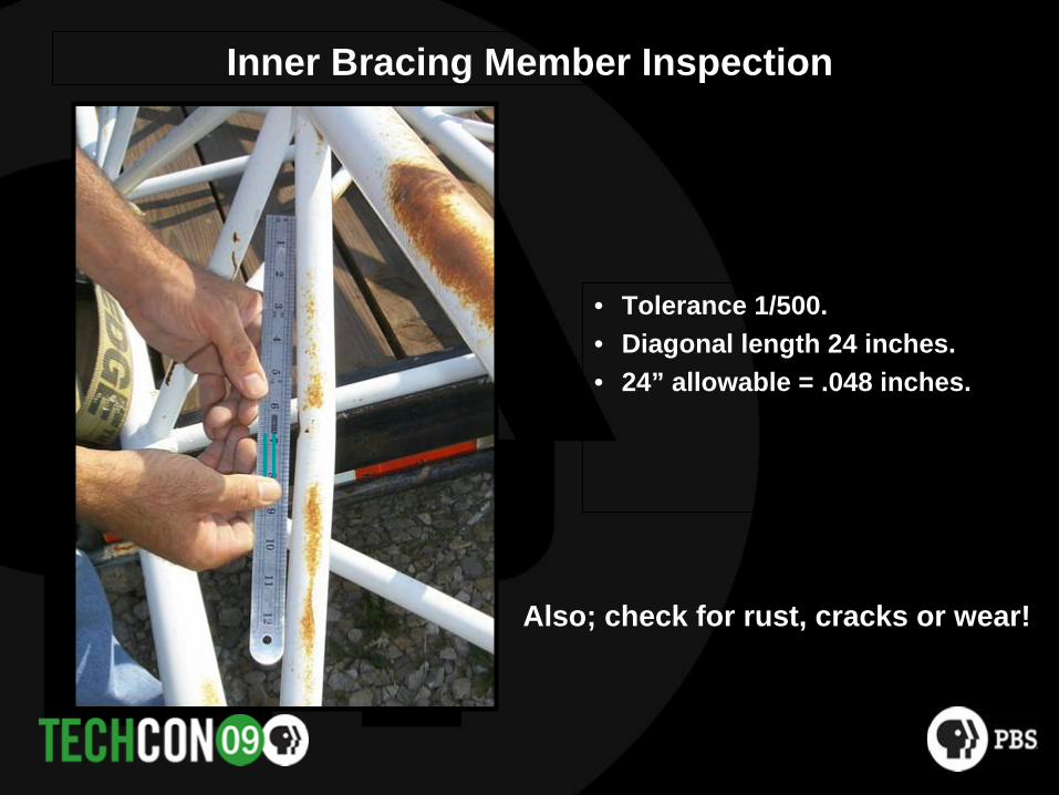
Inner Bracing Member Inspection
• Tolerance 1/500.• Diagonal length 24 inches.• 24” allowable = .048 inches.
Also; check for rust, cracks or wear!
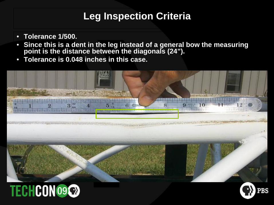
Leg Inspection Criteria
• Tolerance 1/500.• Since this is a dent in the leg instead of a general bow the measuring
point is the distance between the diagonals (24”).• Tolerance is 0.048 inches in this case.

Overall Gin Pole Straightness
• Tolerance 1/500.
• Pole 60 feet long.
• Tolerance 1.55 inches.

Re-Use of Gin Pole Fasteners

High Pole Above Top Level of Guys
Large Cantilever
Top Levelof Guys
•Is when the pole is positioned above the highest level of guys.
•This can only be allowed if the structure can meet the following wind load conditions:
•45 mph during the day•54 mph overnight

Bridle and Basket Forces
• The gin pole attachment forces, where connected to the structure, shall be considered.
• The local forces on individual tower members must be evaluated
• The overall loading on the structure must also be considered.

Gin Pole Analysis and Design
• Scope• Classification of gin poles• Impact factors for gin pole lifts, 1g• Design method• Gin pole forces and reactions• Analysis models• Effective slenderness ratios for compression members• Connections• Rooster head
Gin Pole Design Method
• ASD – AISC-13th Edition
• ASD is the desired design method since the field methods of control and verification are governed by actual deflection of the gin pole and supporting structure under a lifted load condition.

Loading of the Gin Pole Combined Axial and Bending Effects Considered

Gin Pole Free Body Diagrams for Engineering Use

Overall Gin Pole Buckling K-Factors

Impact Factors for Gin Poles (Im)
• Class A Pole – Im = 1.45• Class B Pole – Im = 1.35• Class C Pole – Im = 1.25• Class D Pole – Im = 1.20
For all other cases Im = 1.3

Factors Affecting Gin Pole Loading
• The cantilever height of the gin pole above the bridle.
• The overall length of the pole.• The load line angle at the rooster
head at the top of the pole.• The offset of the rooster head• The number of attachment points to
the structure• The positioning and angle of the tag
line. • Restraint of the load line as it passes
thru the center of the pole• The flexibility of the pole as well as
the structure it is attached to.
º
Basket
Bridle
Vertical

Load Line in Center of Pole
• Restricting, or holding, the load line as it passed down thru the pole helps make it less flexible and can increases its lift capacity.

Design Section for Rooster Heads
Rooster Heads
Bearing

Rooster Head

Rooster Head Design

Track Loading and Design

Rigging Accessories
• 5 to 1 Factor of Safety (10 to 1 if Personnel Involved)
• Rooster Head Sheaves and Bearings • Load, Jump and Tag Lines• Blocks• Headache Ball• Wire Rope Slings, Shackles, Chains, Links and Hooks

Support Conditions Affect Gin Pole Capacity

Cantilever Height• Excessive deflections and high tension loading on leg splices are
typical concerns with cantilevers under construction

250’ Tower-Strength RequirementsCriteria Top Deflection Leg Compression Leg Tension• 54 mph wind 24 inches 14,900 lbs 13,800 lbs (61%)
• Stacking Deflection 12 inches 9,200 lbs 7,100 lbs (31%)
• Guy Wire Slippage 15 inches 8,100 lbs 12,000 lbs (53%)(Impact at 1.3)
• Guy Wire Breakage 15 inches 12,400 lbs 18,400 lbs (82%) (Impact at 2.0)
Leg Splice Tension CapacityLeg Splice Tension Capacity100% Compression Capacity 22,500 lbs 100% Compression Capacity 22,500 lbs 50% Compression Capacity 50% Compression Capacity 11,250 lbs11,250 lbs33% Compression Capacity 33% Compression Capacity 7,500 lbs 7,500 lbs

Guy Anchor Rod Corrosion Probability, Detection & Prevention
Dave DaviesDirector of Structural Products and Services
Electronics Research, Inc.
Guy Anchor Rod Corrosion Foundation Steel Corrosion
• Explanation of the Corrosion Process• How to Self Evaluate Corrosion Risk Probability• Anchor Rod Inspection Methods• Corrosion Prevention Methods

NATE Advertising Campaign
• In a recent advertising campaign, NATE (National Association of Tower Erectors) recommended anchor rod inspection prior to any tower work, out of concern for climber safety.
• Why would this national organization make a recommendation that will double or triple the expense of annual tower inspection and smaller projects?

Tower Failure due to Anchor Rod Corrosion
Because of aDesire for
Self Preservation!

What caused this tower collapse?

Under ground and thus undetected guy anchor shaft corrosion.

Explaining the Corrosion Process. Will all Steel Corrode? NO!
• In non corrosive environments steel naturally forms a protective, tight, non-conducting oxide film on its surface. This process is called “Passivation” because the steel remains passive against its environment.

Why does Steel Corrode?
• If this protective film is removed, Corrosion will occur.
• Once Removed all corrosion is the result of a galvanic cell.

Galvanic Corrosion “un-refines” the metal
• Galvanic corrosion is an electrochemical process where metals deteriorate through a reaction BETWEEN or WITHIN the metals. – Between (External) – metals with different electromotive
potentials. Copper and Steel.– Within (Internal) difference in the environment of two sections of
the same metal. Soil and Concrete or Sand and Clay.

Basic Corrosion Cell Internal or External Corrosion
• 4 Elements of a Corrosion Cell. All must be present for the cell to be active.– Anode– Cathode– Electrical Path (conductor)– Electrolyte
• These four elements are present in both External (between metals) and Internal (same metal) corrosion.

What removes the protective film?
• Electrical Current flow on the surface can cause the protective film to erode.
• Chemicals can erode the film. Highly Acidic or Base soil, farm products, waste.
• Microbiological bacteria can erode the film. Sulfate reducing bacteria resulting in sulfide ions can promote ion flow and limit oxygen in soil.

Causes of Electrical Current
• Difference in the electrical potential of dissimilar connected metals.
• External “Stray” Electrical Current.• Difference in the conductivity of the environment for
a continuous piece of metal.

Electrical Current From Dissimilar Metals
• The voltage difference or potential between copper (-0.43) and carbon steel (-0.68) is .25 volts.
• One ampere - year current flow = loss of 20 pounds of steel.
Metal / Alloy Potential (Volts) Reactivity
Magnesium -1.55 More Reactive
Zinc -1.10
Aluminum -0.86
Cadmium -0.77
Cast Iron -0.68
Carbon Steel -0.68
Stainless Steel -0.61
Lead -0.57
Solder -0.52
Tin -0.49
Copper -0.43
Aluminum Bronze -0.41 Less Reactive
Copper = .43
Steel = .68
1.55
1.10
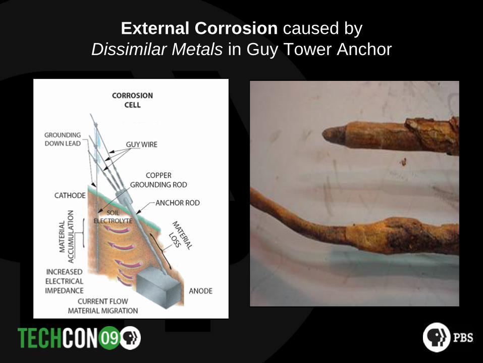
External Corrosion caused by Dissimilar Metals in Guy Tower Anchor

External Corrosion caused by “Stray Currents” in a guyed tower

Internal Corrosion caused by Dissimilar Environments in Guy Anchor

Internal Corrosion caused by dissimilar environments in Self Support Base

Internal Corrosion caused by dissimilar environments in Self Support Base

Internal Corrosion caused by dissimilar environments in Anchor Bolts

Why doesn’t hot dip galvanizing protect the steel from corrosion?
• The main component of galvanizing is zinc. Zinc is very high in the galvanic series and acts as an anode with the coated steel acting as the cathode. When exposed to the atmosphere (CO2) zinc quickly forms its own passivation film.

However, the zinc coating is unstable in the absence of air and quickly erodes

How to Evaluate Corrosion Risk Probability?
• From Geo Tech Report• From Visual, On Site Inspection • From On Site Electrical Testing

Soil Parameters from Geo-Tech Report
• The Soil Classification elements which have the most effect on the corrosion rate are:– particle size and aeration– moisture content– Bactria and microbiologic– pH– Other natural chemical elements

Three ways to report Soil Particle Size From Geo-Tech report
#1Soil Type
#2Particle Size
Corrosion Rate
Sand .07 to 2 mm Low
Silt .005 to .07 mm Moderate
Clay less than .005 mm High
Low Corrosion Rate – Coarse grain soil, less than 50% passing through a # 200 sieve (#3)Higher Corrosion Rate – Fine grain soil, more than 50% passing through a #200 sieve.

Soil Particle Size
• Generally, large particles like rock and sand are well- aerated soils less likely to contribute to corrosion.
• Small Particle, aggressive soils would include:Clay, Silt and compact PeatSandy-Silt in salt water or tidal marshes

Aggressive Soil Types From Geo-Tech report, Soil Classification
Soil Symbol Soil Type
Pt Peat and other highly organic soilsOH Organic clayCH Inorganic clayMH Inorganic silts and very fine sandsOL Organic siltsCL Inorganic clays, silty clays, lean claysML Inorganic silts with fine sandsSC Clayey sands, sand-clay mixturesSM Silty sands, sandy silts

Soil Parameters from Geo-Tech Report
• The following parameters are just a Snap Shot of soil conditions and will change seasonally.
• For reference the following values are for soil which is 75 degrees Fahrenheit.A 20 degree temperature change will double or half corrosion rates.

Moisture Content From Geo-Tech Report
• Usually represented in % moisture by soil weight, or• Difference between in situ soil weight and dry soil weight.
Generally, the greater the moisture content the greater the corrosion probability. Above 15% moisture by weight would be considered aggressive soil.

Bactria and Microbiologic Content From Geo-Tech report
• High levels of bacteria in the soil tend to consume oxygen, thus making the soil poorly aerated and accelerating corrosionBacteria levels can be requested during a geo-tech investigation and should be expected in organic soils like peat or near animal waste sites

Hydrogen Ion Activity (pH) From Geo-Tech Report
• Extreme corrosion rates are to be expected in soils having Low or High pH. The pH range is from 0 to 13, with 7 considered neutral.A reading below 6 or above 8 should be considered as aggressive soil.These soils could include:– Cinder, ash, or slag fills– Organic fills, mine or industrial waste

Chloride Concentration From Geo-Tech Report
• Chloride ions facilitate the corrosion process.• High levels are typically found in areas of historic salt water.• May also result from de-icing operations.
Chloride concentrations in the soil above 50 ppm is consider aggressively corrosive for steel.

Soils with Sulfur From Geo-Tech Report
• Sulfur or sulfur forming soils can produce very acidic soil conditions when exposed to air.
This often occurs in tidal flats or near mining activity where the soil is exposed and well drained.

How to Evaluate Corrosion Risk Probability Using Visual Inspection.
Anchor Shaft

Visual and Agriculture Data Water Level and Rain Fall
• The longer steel remains wet, the higher the corrosion rate.
• Also, plentiful rainfall typically translates into soils that are more acidic and thus, more corrosive.

Visual Inspection Evaluate Site Soil
Road Side ExcavationSandy Soil has low cohesion
Slanted FaceNon aggressive soil
Road Side ExcavationClay has high cohesion
Steep FaceAggressive soil

Visual Inspection Evaluate Site Soil
Surface ObservationClayey Soil has high cohesion
Aggressive soil
Shallow DiggingClayey Soil has high cohesion
Aggressive soil

Another easy way to view soil classification and particle size is through Color.
• Tan, Red or Light Brown color indicates large particle size, well-aerated soil with low moisture content, limited wet duration.
Less Corrosion Probability.
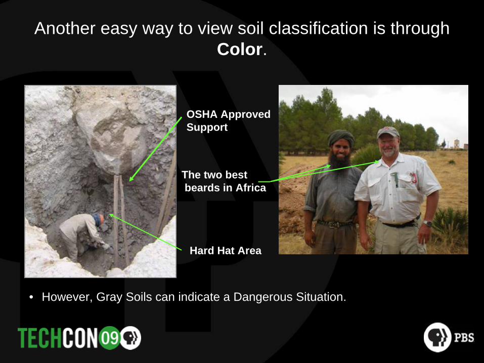
Another easy way to view soil classification is through Color.
• However, Gray Soils can indicate a Dangerous Situation.
OSHA ApprovedSupport
The two bestbeards in Africa
Hard Hat Area

Another easy way to view particle size is through Color.
• Gray and greenish-gray soils indicate small particle size with poor aeration.
Aggressive soil.
Anchor shaft installed less than one year

Visual Inspection Bacteria sources, pH and Agriculture Data,
• Using visual inspection or your nose.
• pH and Bacteria levels can also be obtained from agricultural equipment supplier at no or little cost.
Animal Waste

Visual Inspection of Anchor Shaft

Visual Inspection Look for evidence of Pipe Lines and other stray current sources

National Pipeline Mapping System (NPMS) www.npms.phmsa.dot.gov
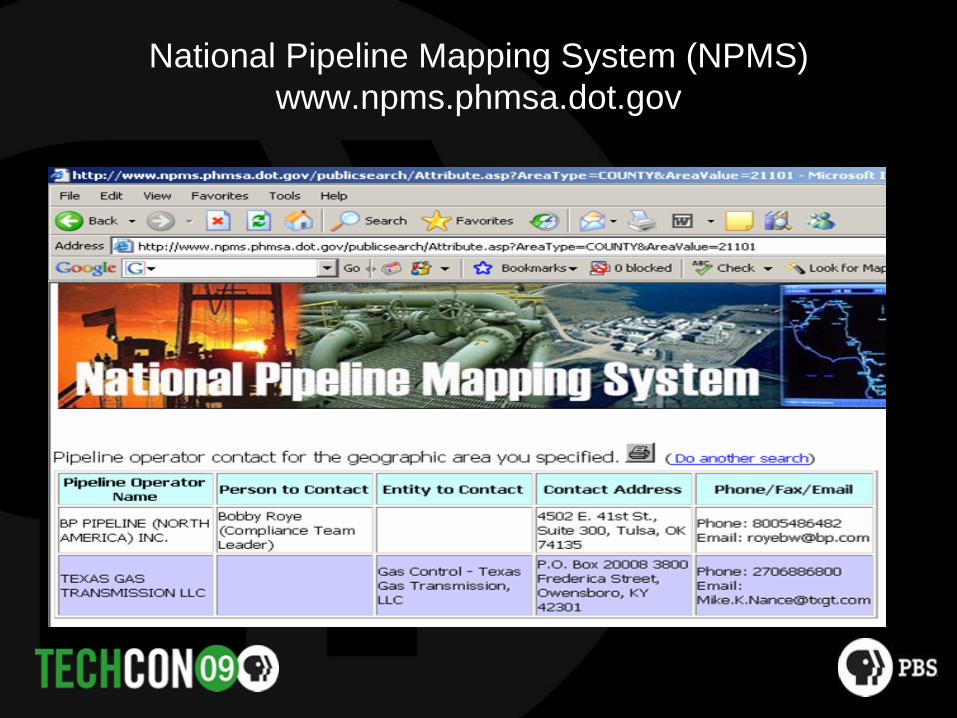
National Pipeline Mapping System (NPMS) www.npms.phmsa.dot.gov

Visual Inspection Look for Other Sources of Stray Currents
• Sources of Direct Electrical Current Generation or Use.– Plating works– DC supply systems in industrial
plants– Large direct drive motors– Welding Equipment– DC communications

Soil Properties, On Site Testing Megger type of test
• High soil resistivity generally equates to a low corrosion rate, and conversely
• Low soil resistivity can lead to a high corrosion rate.Soils with a resistance of less than 10,000 Ohm-Cm would be considered corrosive.

On Site Testing System Resistance and Current Flow
• Measuring the resistance and current in the grounding rod – anchor rod circuit can also be instructive.
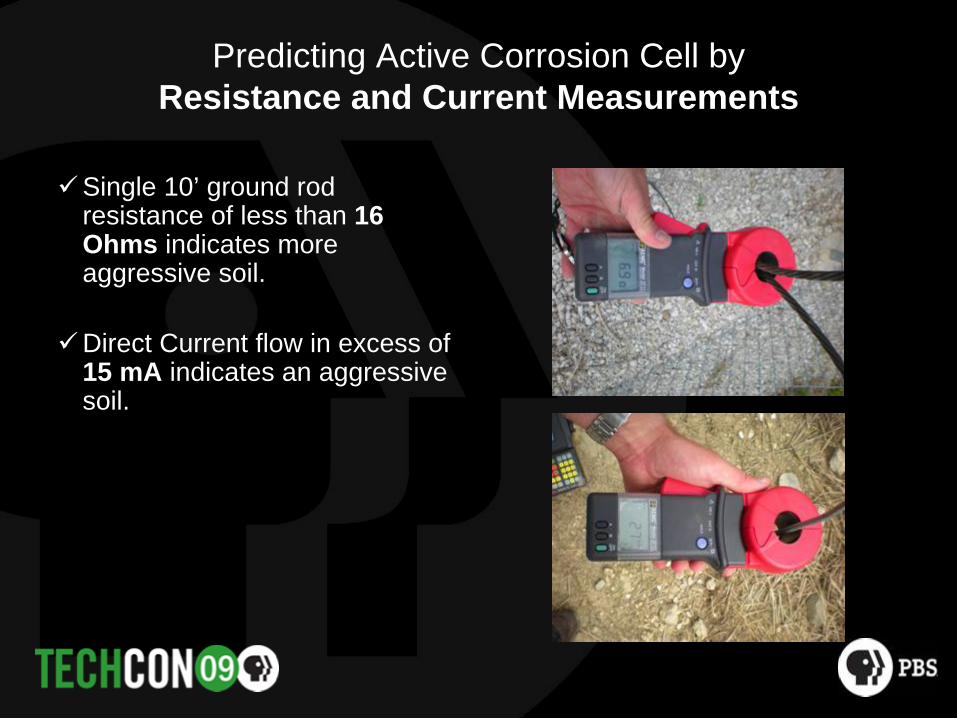
Predicting Active Corrosion Cell by Resistance and Current Measurements
Single 10’ ground rod resistance of less than 16 Ohms indicates more aggressive soil.
Direct Current flow in excess of 15 mA indicates an aggressive soil.

Predicting Active Corrosion Cell by Current Measurements
• Current discharge will cause corrosion loss at the rate of 20 pounds of steel in one year per ampere of discharge.

Predicting Active Corrosion Cell by Direct Current Measurements
• 1 amp-yr = 20 # steel• 27 mA = .027 amps• .027 amp x 20 # steel
= .54 pounds of steel of steel loss in 1 year

Anchor Rod Inspection Methods
• Limited Excavation – limited value• Total Excavation – accurate but expensive and time
consuming• Cylindrical Guided Wave-Ultra Sound

Limited Excavation
• Hand digging around anchor shaft
• Typically 12” to 24” in depth• Assumes “if Corrosion is found
need to dig up anchor.”• If “Not found no need for further
investigation.”

Limited Excavation
Not representative of Rod condition

Limited Excavation
Mud
Ground Level

Total Excavation

Total Excavation
• Expensive• Can be destructive• Dangerous• Difficult to repeat

Sometimes you can’t Dig
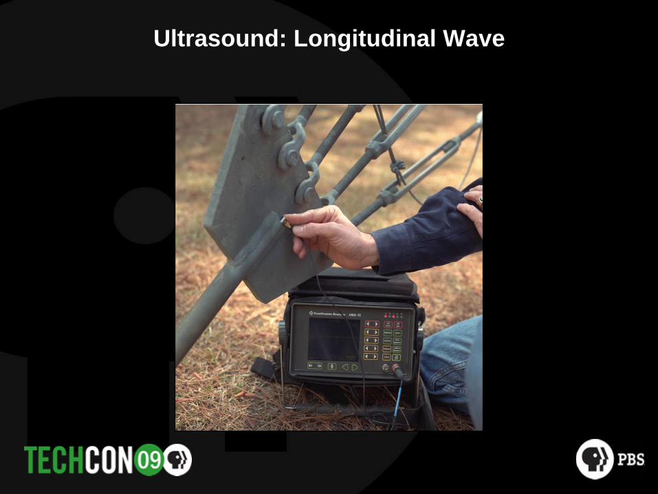
Ultrasound: Longitudinal Wave

Ultrasound: Longitudinal Wave
Entry surface
Back-wall reflection
Unflawed Anchor Flawed Anchor
Typical of planarflaw (crack)
Flawed Anchor
Typical of wastage

Ultrasound: Limited Surface Area, so Small Transducer limits testing ability

Beam Spread
Transducer BeamDiameter Spread
3/8 inch 48 degrees1/2 inch 34 degrees¾ inch 22 degrees1 inch 16 degrees

Field Application of Longitudinal Wave with Small Transducer
No Back Wall Reflection

Field Application of Longitudinal Wave Stress Cracks in Anchor Shaft
Stress Crack

Ultrasound: Shear Wave, also called “Guided Wave”

Ultrasound: Shear Wave

Ultrasound: Shear Wave
Loud Entry Noise
No Back Wall Reflection

Making Longitudinal Wave Ultra Sound Work
• Problems– Can’t dig– Can’t get to the end of the shaft– Shaft is too long for Shear wave
method
Time to be inventive!

Making Longitudinal Wave Work

Making Longitudinal Wave Work
Loud Entry Noise
Nice Back Wall Small Back Wall
Typical Corrosion

Limiting Factors in using Ultra Sound
• Diameter of anchor rod. Small diameter offers increased resistance.
• Length of anchor rod. Longer rod offers increased resistance.• Access or insertion point. Determines the size and type of probe
to be used.• Altering Anchor Rod requires Structural Analysis• Ultra Sound is the most promising method of anchor rod
inspection.

Especially if you can change the design. ULTRA™ Guy Anchor Rod by ERI

20’ x 2-1/2” dia Rod, 25% x-section area removed. Test area, 12” in length, 6.5’ from one end.

ULTRA™ Test Results

Ultra Sound Field Results

Corrosion Prevention Methods
• If we can disrupt the electrical circuit we can reduce the corrosion rate.– Concrete Encasement– Coatings– Impressed Counter Current– Sacrificial Anodes

Concrete Encasement
• Associated Problems– Expense– Corrosion can still occur under
the concrete– Cracks

Coatings
Anchor shaft with Plastic Tape
Anchor shaft with tar adhesive

Coatings
Associated Problems• Difficult to apply in the field• If factory applied,
susceptible to shipping and installation damage
• If damaged, accelerated corrosion

Impressed Counter Currents
Associated Problems• Expensive• Difficult to Maintain• Over protections can lead to
corrosion• May lead to increased corrosion
rate in non protected structures

Sacrificial Anodes
Associated Problems• Maintenance• Can increase Grounding
System Resistance

Increased Electrical Resistance as a Result of Galvanic Corrosion Action

A Better Sacrificial Anode MAG-Rod™ by ERI
• Chemical Grounding Rod.and
• Sacrificial Anode

MAG-ROD™ Galvanic Corrosion Protection
Summary
• Corrosion begins when the steel looses the protective film.• The film is destroyed by its environment or electrical current.• Zinc Galvanizing alone is not sufficient protection.

Summary
• Evaluate the corrosion risk by knowing the soil characteristics, visual observations, and/or by measuring current flow.
• Interrupting the galvanic cell will reduce corrosion possibility.• Reversing the polarity of the galvanic cell will prevent
corrosion.

Summary Ultra Sound is the most promising Inspection Method for Inspection and
Detection.

Questions
Dave DaviesDirector, Structural Products and ServicesElectronics Research, [email protected]
Thomas B. SillimanPresidentElectronics Research, [email protected]

Construction Standards &
Guy Anchor Rod Corrosion Probability, Detection & Prevention
See us at the’09 NAB in Booth C1307!