Towards Timely Intelligence in the Power Grid
14
44 th Annual Precise Time and Time Interval (PTTI) Systems and Applications Meeting 399 Towards Timely Intelligence in the Power Grid Julien Amelot 1 , Dhananjay Anand 2 , Thomas Nelson 1 , Gerard Stenbakken 1 , Ya-Shian Li-Baboud 1 , and James Moyne 2 1 National Institute of Standards and Technology, 100 Bureau Drive, Gaithersburg, MD U.S.A. 2 University of Michigan Ann Arbor, Ann Arbor, MI U.S.A. [email protected] Abstract—One of the key lessons learned from the 2003 Northeast Blackout in the United States was the need for improved grid timing and synchronization. The problem began as an isolated issue, but cascaded through the Northeastern grid. Timely situational awareness would likely have contained the area affected by the blackout. To attain situational awareness over a large scale requires synchronized time. Synchronized time enables merging data from remote sources, maintaining tolerable measurement uncertainty, and forensic analysis to build knowledge on preventing future problems. Phasor measurement units (PMUs) rely on global synchronized time to consolidate measured data points from remote substations on the grid allowing situational awareness and the ability to anticipate potential issues and take the necessary corrective actions to prevent or minimize loss of power. Global synchronized time is currently being provided by the Global Positioning System (GPS); however, potential issues and limitations motivate another precision timing solution. Network time synchronization, particularly IEEE 1588 Precision Time Protocol (PTP), can reliably sustain sub-microsecond time precision. The National Institute of Standards and Technology (NIST) has developed a timing testbed to characterize, assess, and monitor the performance of network timing in various test scenarios. Furthermore, in conjunction with the NIST Synchrophasor Lab, a prototype IEEE 1588 PMU was built and tested. The metrics, software and test methods developed would enable substations, manufacturers of power systems equipment, and IEEE 1588 certification labs to ensure their 1588 network and products can meet the requirements of next-generation power grids. The paper provides the motivation and applications for the NIST timing testbed, and highlights the metrics, test methods and software tool that have been developed. Key words: network time synchronization, power grid, Smart Grid, testbed, phasor measurement units, 1588 I. INTRODUCTION An aspect of the Smart Grid vision is one in which the power grid is capable of monitoring and healing itself [1]. Improved autonomy in power grid control will require the ability to measure and gather necessary data for assessing grid health and resource availability, a reliable network to communicate the data, and dynamic, high-fidelity computational models to make timely, intelligent decisions to minimize adverse impacts. Many technical challenges exist in coordinating and maintaining supply and demand within the grid. Electricity flows at close to the speed of light and is currently not economical to store [2]. Therefore the grid must continuously balance the generation and demand of the electricity in real-time. One of the largest and most complex grids, the North American electricity grid, is comprised of interconnects, with the contiguous U.S. covered by the Eastern Interconnection, Western Interconnection and Electric Reliability Council of Texas (ERCOT) Interconnection (Figure 1). Interconnects enable the grid to compensate for local variations in the load and generation [3]. However, interconnects also increase the potential risk of large system disturbances such as cascading blackouts. The history of large-scale blackouts began shortly after the electric systems in North America became interconnected [4]. With the Eastern Interconnect established in 1962, the first large-scale event
Transcript of Towards Timely Intelligence in the Power Grid

44th Annual Precise Time and Time Interval (PTTI) Systems and Applications Meeting
399
Towards Timely Intelligence in the Power Grid
Julien Amelot1, Dhananjay Anand
2, Thomas Nelson
1, Gerard Stenbakken
1, Ya-Shian Li-Baboud
1, and
James Moyne2
1National Institute of Standards and Technology, 100 Bureau Drive, Gaithersburg, MD U.S.A.
2University of Michigan Ann Arbor, Ann Arbor, MI U.S.A.
Abstract—One of the key lessons learned from the 2003 Northeast Blackout in the United States was the need
for improved grid timing and synchronization. The problem began as an isolated issue, but cascaded through
the Northeastern grid. Timely situational awareness would likely have contained the area affected by the
blackout. To attain situational awareness over a large scale requires synchronized time. Synchronized time
enables merging data from remote sources, maintaining tolerable measurement uncertainty, and forensic
analysis to build knowledge on preventing future problems. Phasor measurement units (PMUs) rely on global
synchronized time to consolidate measured data points from remote substations on the grid allowing
situational awareness and the ability to anticipate potential issues and take the necessary corrective actions to
prevent or minimize loss of power. Global synchronized time is currently being provided by the Global
Positioning System (GPS); however, potential issues and limitations motivate another precision timing
solution. Network time synchronization, particularly IEEE 1588 Precision Time Protocol (PTP), can reliably
sustain sub-microsecond time precision. The National Institute of Standards and Technology (NIST) has
developed a timing testbed to characterize, assess, and monitor the performance of network timing in various
test scenarios. Furthermore, in conjunction with the NIST Synchrophasor Lab, a prototype IEEE 1588 PMU
was built and tested. The metrics, software and test methods developed would enable substations,
manufacturers of power systems equipment, and IEEE 1588 certification labs to ensure their 1588 network
and products can meet the requirements of next-generation power grids. The paper provides the motivation
and applications for the NIST timing testbed, and highlights the metrics, test methods and software tool that
have been developed.
Key words: network time synchronization, power grid, Smart Grid, testbed, phasor measurement units, 1588
I. INTRODUCTION
An aspect of the Smart Grid vision is one in which the power grid is capable of monitoring and healing
itself [1]. Improved autonomy in power grid control will require the ability to measure and gather
necessary data for assessing grid health and resource availability, a reliable network to communicate the
data, and dynamic, high-fidelity computational models to make timely, intelligent decisions to minimize
adverse impacts.
Many technical challenges exist in coordinating and maintaining supply and demand within the grid.
Electricity flows at close to the speed of light and is currently not economical to store [2]. Therefore the
grid must continuously balance the generation and demand of the electricity in real-time.
One of the largest and most complex grids, the North American electricity grid, is comprised of
interconnects, with the contiguous U.S. covered by the Eastern Interconnection, Western Interconnection
and Electric Reliability Council of Texas (ERCOT) Interconnection (Figure 1). Interconnects enable the
grid to compensate for local variations in the load and generation [3].
However, interconnects also increase the potential risk of large system disturbances such as cascading
blackouts. The history of large-scale blackouts began shortly after the electric systems in North America
became interconnected [4]. With the Eastern Interconnect established in 1962, the first large-scale event

44th Annual Precise Time and Time Interval (PTTI) Systems and Applications Meeting
400
was the Northeast blackout of 1965 affecting more than 30 million people for up to 13 hours. As a result,
the North American Electric Reliability Council (NERC) was established by the electric utility industry to
ensure the bulk electric system was reliable, adequate and secure [4]. Blackouts can have significant safety
and economic impact. The Northeast blackout of 2003 affected more than 50 million people, contributed to
11 deaths and had an estimated cost of $6 billion [3].
Figure 1. North American interconnects in the electrical grid.
The current grid consists of a hybrid of modern and legacy measurement and control equipment, which
makes it a challenge to dynamically track disturbances. Furthermore there are insufficient monitoring and
control mechanisms to isolate power disturbances. Grid control operators view data that are both sparse
and at least 30 seconds old [5], which makes it impossible to detect and isolate cascading blackouts that are
occurring on the order of tens of seconds [6].
The Smart Grid envisions a means to provide a planned nationwide network that uses information
technology to deliver electricity efficiently, reliably and securely and permit a bi-directional flow of both
electricity and information [7]. The National Institute of Standards and Technology (NIST) Smart Grid
Conceptual Model, Figure 2, depicts a communication network comprising market, operations, service
provider, bulk generation, transmission, distribution and customer. To provide situational awareness and
intelligence, a multi-resolution, high fidelity, dynamic model must be available to detect nascent deviations
and to reconfigure itself to isolate the problem while continuing to meet the customer demands on
generation, transmission and distribution [5].
Figure 2. NIST Smart Grid Conceptual Model.

44th Annual Precise Time and Time Interval (PTTI) Systems and Applications Meeting
401
II. SYNCHRONIZED TIME IN THE POWER GRID
A. Why is Synchronized Time Important?
Synchronized time is important for analyzing system disturbances, maintaining situational awareness, and
also for providing timely remedial actions to prevent system instabilities such as brownouts and cascading
blackouts. Analysis of the 2003 blackout by NERC included the recommendation to ―install additional
time-synchronized recording devices as needed [8].‖ The recommendation came after it took two months
to establish the exact sequence of events to understand the root causes that led to the cascading blackout.
Leveraging the lessons learned from the 2003 blackout, the post mortem analysis of the 2011 Southwest
blackout - in which a sequence of over 100 notable events for a duration of 11 minutes was constructed -
was a much more efficient process [6]. However, the timeline for root cause analysis still took two days to
establish. The delays were attributed to varied time-stamping methodologies, formats, and sources of
synchronization, where not all of the time-stamps were synchronized to the NIST standard clock in
Boulder, Colorado [8].
In order to execute remedial actions to prevent cascading failures, the sequence of events need to be
established in real-time, and physical models of the system must be updated continuously and
instantaneously. Reports from both blackouts cite the need for improved real-time situational awareness.
Without understanding of real-time operational maintenance and resource availability, a problem affecting
one area of the grid can rapidly, within minutes, cascade to affect neighboring transmission and
distribution lines. A clear understanding of the operational, health, and power demand conditions is
necessary to take timely remedial actions.
In addition to establishing the sequence of events, control system operators for the electrical power grid
rely on the estimated state of the power system to make control decisions. For improved accuracy of the
state estimation, it is necessary to feed existing estimators with higher frequency real-time measurements
to understand the transient dynamics of the physical processes. Synchrophasors, which use global time to
serve as a reference for measuring current and phasor measurements, provide a means to measure the real-
time health of the grid. Phasor Measurement Units (PMUs) are therefore essential to realize the goals of
situational awareness and intelligence. As time serves as a reference, timing jitter directly translates to
uncertainty in the phasor measurements.
Figure 3 illustrates a steady-state wave form of a power signal (green) and how simulated intermittent steps
in the time can manifest as phase shifts in the measured signal (red). To account for the reference noise,
control models must allow for a tolerance bound (yellow), which contributes to the uncertainty of the
phasor measurement. The simulated intermittent phase shifts are caused by four time synchronization
updates over one period which lasts 16.67 ms for a 60 Hz signal. The simulation is intended to provide a
visual of how inaccurate time synchronization can create uncertainty in phasor measurements. For
illustration purposes, the 1 ms offset is an overestimated error, as the power industry clocks can maintain
time accuracy within one microsecond. In practical situations, the synchronization update would not occur
as frequently. Distributed time synchronization algorithms tend to slew the time for synchronization
correction to ensure time does not jump forward or backward. When timing uncertainty is the sole source
of error, 26 μs translates to 1 percent Total Vector Error (TVE), while a 1 ms offset becomes a 38 percent
TVE. With more reliable and robust timing precision, tighter tolerance bounds can be achieved. Lower
uncertainty thresholds would enable earlier detection of nascent discrepant behavior.

44th Annual Precise Time and Time Interval (PTTI) Systems and Applications Meeting
402
Figure 3. Inaccurate time updates can manifest as phase shifts.
B. Methods and Challenges of Distributed Time Synchronization
The U.S. power grid currently uses the Global Positioning System (GPS) to provide a common source of
Coordinated Universal Time (UTC). Due to the wide area of the grid, this is the most economical solution
across transmission and distribution channels. The GPS has a timing accuracy of 100 ns. The uncertainty
of the UTC time is also dependent on the GPS receiver. Relying solely on GPS leads to several issues.
Within an electrical substation, there are devices that may not have a line of sight to the GPS or require
additional ports to configure access to GPS synchronized equipment. GPS can also become unavailable
due to varying atmospheric conditions, unintentional interference, or malicious attack. It has been
demonstrated that GPS is also susceptible to attacks including spoofing [9] and jamming [10].
Within a substation, Inter-Range Instrumentation Group (IRIG)-B signals can be used to propagate time to
devices. IRIG-B is designed to guarantee one millisecond resolution and accuracy. Because the
unmodulated IRIG-B signal is a digital signal, which can have the fundamental accuracy of digital logic,
IRIG-B signal generation hardware can be built to support microsecond resolution and accuracy [11]. Sub-
microsecond accuracy must take into account propagation time and ringing. IRIG-B also requires a
dedicated coaxial cable or twisted-pair connection.
Network-based timing uses the commonly available Ethernet data port, which eases the dissemination of a
traceable time source and is more robust under varying atmospheric conditions than sources based on
satellite. With the Network Time Protocol (NTP) and its simplified form, Simple Network Time Protocol
(SNTP), accuracies can be achieved on the order of milliseconds. The challenges of the network-based
timing protocol lies in the non-deterministic nature of Ethernet. Determinism is one of the keys to
achieving sub-microsecond accuracy. Most network-based protocols rely on symmetrical round trip delays.
Network jitter or packet delay variation (PDV), can degrade accuracy since the offsets are calculated based
on round trip delay of the time packet, divided by two. Queues in the switch and differing sources of the
time-stamps can all contribute to variation in end-to-end network delays. However, there are kernel level
and hardware optimizations that can be made to improve the determinism. IEEE 1588, the Precision Time
Protocol (PTP), provides several standardized mechanisms to achieve greater determinism. To minimize
jitter on the network stack, accurate timestamps must be generated at the Physical layer of the Open
System Interconnection (OSI) Network Stack Model [12]. Within the network, Transparent Clocks provide
a known residence time, thereby minimizing the impact of jitter due to queuing delays. IEEE 1588 can
readily achieve sub-microsecond accuracies with the use of hardware time-stamping on network nodes.
However, without proper network security countermeasures in place, IEEE 1588 and other network-based
timing are susceptible to a variety of attacks including spoofing, masquerade, and denial of service (DoS).

44th Annual Precise Time and Time Interval (PTTI) Systems and Applications Meeting
403
C. Industry Standards
The IEEE Standard C37.118 for Synchrophasor Data Transfer for Power Systems requires the vector
difference between the measured and ideal phase and magnitude values to be on the order of 1 percent
TVE [13]. However, the TVE is an aggregation of errors based on instrumentation conversion latencies,
phasor measurement processing latencies, and time synchronization offsets [14]. If timing was the only
source of error, the time precision budget would be 26 µs at 60 Hz. However, due to other sources of
errors, the error budget for time uncertainty is reduced to the 1 µs requirement specified in the IEEE 1588
Power Profile [12]. While the 1 µs goal is effective for situational awareness and fault detection, it has yet
to be determined if the timing accuracy would be sufficient in providing information to achieve the
measurement uncertainty needed for real-time dynamic modeling of grid conditions to realize fault
anticipation and situational intelligence.
The importance of time synchronization in the power grid has led to several industry-specific timing
standards. One of the standards is IEEE C37.238, the IEEE Standard Profile for Use of IEEE 1588
Precision Time Protocol in Power Systems Applications [12]. The profile provides additional
specifications to IEEE 1588 to ensure the power system requirements are met. A NIST testbed originally
envisioned for developing test methods for distributed timing performance and providing a venue to
develop prototypes of distributed network timing measurement and control techniques has been expanded
to ensure scenarios over at least 16-network hops can be established.
The International Electrotechnical Commission (IEC) 61850 is a key communication standard for
substation automation and protection field equipment operating under real-time or non-real time conditions
[15]. The Smart Grid Priority Action Plan (PAP) 13 group, tasked to harmonize the IEEE C37.118 and IEC
61850, coordinated the development of IEC/Technical Report 61850 Part 90-5: Use of IEC 61850 to
transmit synchrophasor information according to IEEE C37.118. The standard provides a means of
propagating synchrophasor data from PMUs to Phasor Data Concentrators (PDCs) to the Wide Area
Monitoring, Protection, and Control (WAMPAC) and other control center applications. The standard also
specifies how to harmonize the time-stamp formats between IEEE C37.118 and IEC 61850 [15].
III. THE NIST TIMING TESTBED
The NIST timing testbed, as shown in Figure 4, was envisioned to provide a venue to develop
measurement and test tools to assess the feasibility, reliability, and robustness of meeting the timing
requirements in the power grid. The initial goal was to create measurement tools for the performance of
IEEE 1588 in various aspects including, but not limited to, accuracy, reliability, security, and conformance.
Figure 4. A sample view of the NIST IEEE 1588 Testbed.
44th Annual Precise Time and Time Interval (PTTI) Systems and Applications Meeting
404
A. Measurement Tools and Metrics
The testbed includes several methods for measuring the timing offset between the source and the network
nodes. The oscilloscope has sub-nanosecond uncertainty, but is limited by the number of devices it can
measure. In order to ensure scalability to a large number of devices with minimal cost to measurement
accuracy, a digital measurement device was developed that measures up to 64 devices simultaneously with
a time uncertainty of 8 ns, which is well below the industry requirements. A complete software
measurement tool, the PTP Dashboard, based on the reported offsets from the PTP clock’s management
node messages was also developed. The dashboard measurement data can be verified with the data
acquisition card while providing a visualization of the PTP network and device stability over time [13].
Based on the measurement tools, several characteristics of the PTP devices can be readily measured and
observed. With respect to the slave node, the offset, the histogram over time of the offsets, the mean path
delay, convergence rate, and holdover rate can be assessed. Network measurements are also an important
aspect in understanding the stability of the system. The dashboard enables a view of the peer-to-peer delays
for Transparent Clocks (TCs).
B. Devices
The testbed was created to ensure practical test scenarios can be deployed, short of having an actual
substation network. Table 1 specifies the current devices available in implementing the test scenarios. The
testbed has a PTP network comprising the UTC time source (GPS antenna connected to the PTP
Grandmaster), the distributed ordinary clock (OC) nodes which simulate time synchronized Intelligent
Electronic Devices (IEDs) in the substation, and PTP transparent and boundary clocks (TC and BC,
respectively). To determine offset accuracy, each node can output a Pulse Per Second (PPS) signal, which
can then be simultaneously measured with an oscilloscope and a data acquisition card to verify the
accuracy of the offset measurements. To ensure scalability of the simultaneous measurement of the offsets
between grandmasters and slave nodes, the management node can run the PTP Dashboard software to
provide a general view that the timing precision in the network is maintained within industry
specifications. The accuracy of the PTP Dashboard measurements has been corroborated with the data
acquisition card and oscilloscope to ensure it reports the results accurately. The network traffic generator
device contains multiple Ethernet ports to provide simultaneous injection of traffic at varying loads and
patterns. Since Ethernet is especially prone to non-deterministic behavior under stressed network
conditions, the traffic generator evaluates the implementations of the TCs ability to accurately measure
residence times under device duress.
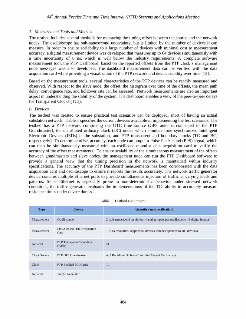
Table 1. Testbed Equipment.
Type Device Quantity (and specification)
Measurement Oscilloscope 2 (sub-nanosecond resolution, 4 analog inputs per oscilloscope, 16 digital inputs)
Measurement FPGA-based Data Acquisition
Card 1 (8 ns resolution, supports 64 devices, can be expanded to 200 devices)
Network PTP Transparent/Boundary Clocks
21
Clock Source PTP GPS Grandmaster 4 (1 Rubidium, 3 Oven-Controlled Crystal Oscillators)
Clock PTP Enabled PCI Cards 10
Network Traffic Generator 1

44th Annual Precise Time and Time Interval (PTTI) Systems and Applications Meeting
405
C. PTP Dashboard
A Java-based open source software measurement, configuration, and test deployment tool, the PTP
Dashboard, provides visualization for easy assessment and understanding of the network timing
performance as well as longer term PTP network and device stability [16]. The measurement results from
the dashboard can be verified with the PPS data acquisition board. The dashboard also includes a prototype
implementation of automated conformance testing that not only verifies the implementation of the message
but also whether the behavior of the device is what it claims to be. If the device claims to have a
synchronization interval from 2-3
to 23
s, the dashboard would compute the average number of
synchronization packets received for each of the specified intervals. Figure 5 shows the graphical user
interface of the dashboard, which is based on the information and control using the standard management
messages. Because the dashboard assumes correct and sufficient implementation of management
messages, not all of the options may be available if the management node messages are not implemented
by the PTP device. The dashboard can provide configuration of the devices through the standard set of
management messages. Furthermore, vulnerability tests can be readily deployed with the options available
in the upper left hand corner.
Figure 5. The PTP Dashboard enables monitoring and configuration of the network as well as automated
deployment of different test profiles and scenarios.
D. Test Scenarios
Our test scenarios are based on several criteria related to timing accuracy, reliability, and interoperability.
With respect to timing accuracy, test methods are used to examine how network loads, patterns and

44th Annual Precise Time and Time Interval (PTTI) Systems and Applications Meeting
406
topology can impact distributed timing performance. Tests were also developed to observe the
implementation aspects such as convergence rates and holdover [16]. As shown in Figure 6a, the
convergence test enables statistical analysis by allowing the user to run the experiment multiple times
automatically. Automated testing is particularly useful for experiments that have non-characterized
parameters impacting timing accuracy, such as the state of the quartz, the environmental temperature,
algorithms, etc. A large number of iterations would provide more statistically significant results. Each
iteration had a different maximum offset ranging from a little over 2 µs to within 500 ns before the device
converged. Given that critical applications require anticipation of worst case scenarios, OC4 can be
estimated to converge within 1 minute after a cold start. Figure 6b illustrates the effect of different clocks
and their drift rates during a holdover test. Device C4 has an Oven-Controlled Crystal Oscillator (OCXO),
have the lowest drift rate; one experimental iteration showed the clock was within 1 µs for up to 5 minutes.
The other devices with Temperature-Controlled Crystal Oscillators (TCXO) drifted over the threshold
(outlined in black) in about one minute. Additional tests include how the clocks’ accuracies respond to
different synchronization intervals (Figures 7a and 7b) [17]. The OCXO clock can sustain longer
synchronization intervals of up to 8 seconds while maintaining a standard deviation of less than 16 ns. On
the other hand, TCXO clocks quickly degrade at synchronization intervals of 2 s and above. One point to
note is Device A, which has a TCXO clock but the standard deviation was only slightly higher than the
OCXO clock at around 20 ns. The behavior demonstrates that clock quality is not the only attribute
affecting precision performance. Algorithms can be optimized to compensate for lower clock quality. To
ensure the robustness of the results a large number of iterations and prolonged durations should be
assessed. The number of iterations, the duration of each test and test conditions will have to be specified by
industry based on practical operating conditions before device convergence and holdover behavior can be
effectively characterized for critical grid applications. The testbed provides a prototype of what tests can be
done and can provide further guidance in device characterization.
(a) (b)
Figure 6. The testbed provides test scenarios to characterize clock behavior. (a) Statistical analysis of convergence
of an ordinary clock (OC) and (b) drift rates of a set of OCs during a holdover test.

44th Annual Precise Time and Time Interval (PTTI) Systems and Applications Meeting
407
(a) (b)
Figure 7. Clock precision response to frequency of synchronization (a) expressed as standard deviation of offset
from the master for five different slave devices (with C3 as an OCXO device and all others as TCXO devices) and
(b) as a histogram of the frequency of offset over time for a single TCXO device.
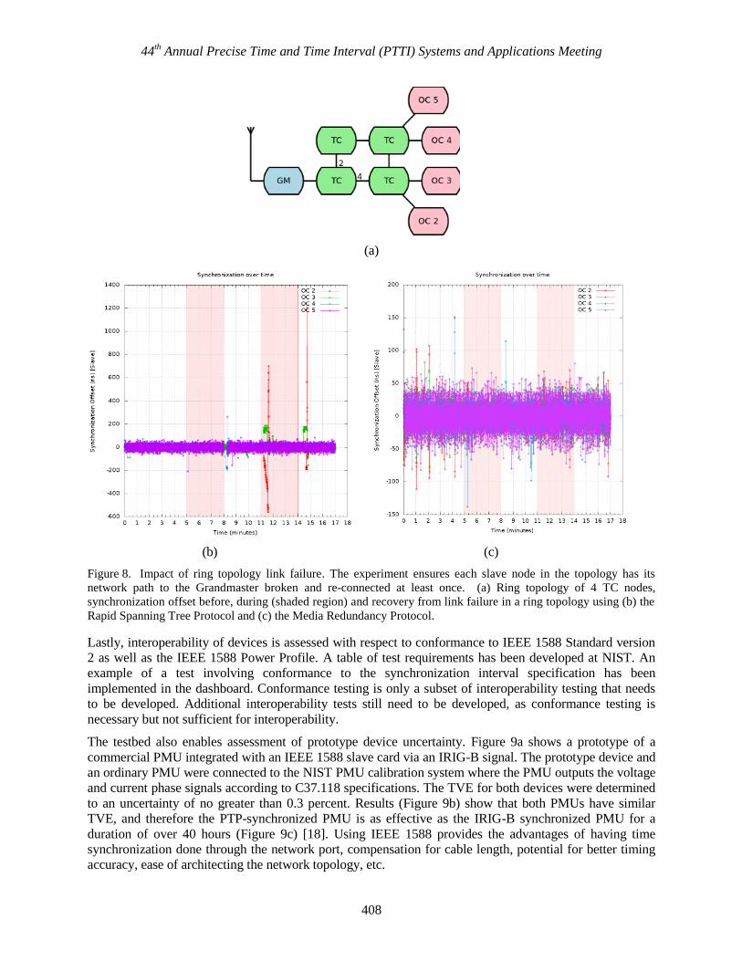
Reliability is assessed in terms of susceptibility to security vulnerabilities, stressed network conditions, and
network synchronization resilience to a Grandmaster switch. Previous work has reported that some devices
were susceptible to masquerade when integrated into the network in default mode [17]. The attacks
implemented in the PTP Dashboard include masquerade, DoS, and multicast poisoning. Another failure
condition occurs when a link in the network topology becomes unresponsive. Ring topology is typically
used in critical applications as it prevents a single point of failure. The ring topology can be set up as
shown in Figure 8a. Depending on the ring protocol implemented, the resilience of the timing protocol can
be affected [16]. With the Rapid Spanning Tree Protocol (RSTP), the network did not maintain the
required timing precision. When the link fails in RSTP, packets are not routed correctly, leading to packet
loss. The protocol takes tens of seconds to recover from the failure scenario. The poor synchronization
performance is due to lost packets during the link failure. Regardless of the quality of the quartz, the
synchronization accuracy of the slave node can be impacted by the loss and re-route of the packets. The re-
route of the packets can introduce path delay variation (PDV) depending on the location of the node. In
contrast, with the Media Redundancy Protocol (MRP), where there is a guarantee to respond to a link
failure on the order of tens of milliseconds, the results after a link failure show a consistent synchronization
offset well within 200 ns range after 50 runs [16].
Offset (Proportion)
44th Annual Precise Time and Time Interval (PTTI) Systems and Applications Meeting
408
(a)
(b) (c)
Figure 8. Impact of ring topology link failure. The experiment ensures each slave node in the topology has its
network path to the Grandmaster broken and re-connected at least once. (a) Ring topology of 4 TC nodes,
synchronization offset before, during (shaded region) and recovery from link failure in a ring topology using (b) the
Rapid Spanning Tree Protocol and (c) the Media Redundancy Protocol.
Lastly, interoperability of devices is assessed with respect to conformance to IEEE 1588 Standard version
2 as well as the IEEE 1588 Power Profile. A table of test requirements has been developed at NIST. An
example of a test involving conformance to the synchronization interval specification has been
implemented in the dashboard. Conformance testing is only a subset of interoperability testing that needs
to be developed. Additional interoperability tests still need to be developed, as conformance testing is
necessary but not sufficient for interoperability.
The testbed also enables assessment of prototype device uncertainty. Figure 9a shows a prototype of a
commercial PMU integrated with an IEEE 1588 slave card via an IRIG-B signal. The prototype device and
an ordinary PMU were connected to the NIST PMU calibration system where the PMU outputs the voltage
and current phase signals according to C37.118 specifications. The TVE for both devices were determined
to an uncertainty of no greater than 0.3 percent. Results (Figure 9b) show that both PMUs have similar
TVE, and therefore the PTP-synchronized PMU is as effective as the IRIG-B synchronized PMU for a
duration of over 40 hours (Figure 9c) [18]. Using IEEE 1588 provides the advantages of having time
synchronization done through the network port, compensation for cable length, potential for better timing
accuracy, ease of architecting the network topology, etc.

44th Annual Precise Time and Time Interval (PTTI) Systems and Applications Meeting
409
(a) (b)
(c)
Figure 9. Reference implementation of a IEEE 1588-based PMU. (a) The reference implementation and test
system. (b) shows the results of the TVE from both the direct and IEEE 1588 link and (c) shows the synchronization
offsets between the IEEE 1588 Grandmaster (GM) and the GPS clock (bottom graph) as well as the offsets between
the IEEE 1588 OC and the GPS clock (top graph) to demonstrate that the time is independently compared.
The test scenarios enumerated above are just the tip of the iceberg towards providing a research venue to
understand performance capabilities and development of metrics to characterize network timing behavior.
IV. TOWARDS SITUATIONAL INTELLIGENCE
The term situational intelligence relates to improving the ability of a network operator to respond to
disturbances such as outages and load/capacity fluctuations. Typically, situational intelligence
encompasses automated model-based control and real time diagnosis functions. Precise clocks are essential
to the performance of both these functions especially over large areas where communication bandwidth
may be limited.
Improved analysis and evaluation tools for modeling, simulation, and control that leverage precise clock
synchronization are currently being explored by NIST collaborators at the University of Michigan. The

44th Annual Precise Time and Time Interval (PTTI) Systems and Applications Meeting
410
NIST timing testbed can be augmented to test and evaluate how changes in timing accuracy affect
situational intelligence.
Electrical power control stations use state estimation based on measurements from substations to monitor
the state of the power system. Algorithms have been designed to leverage accurate clocks to improve the
model-based control of phase and frequency within low voltage distribution circuits [19]. Figure 10 shows
a hybrid implementation of a model ―M” and a physical process ―P‖ running in parallel. In a hybrid system
a control input in the form of a user specified set point or a target state (Vref) is transmitted to both M and P
simultaneously. An accurate model is essential to reliably estimate the state of the physical system ( ). To
ensure that the estimate tracks under all operating conditions, the model used for control must be
continuously updated with data from the physical process. Network measurements suffer degradation due
to delays in propagation or due to bandwidth constraints. Time skews in the data acquisition process and
the time it takes for the state estimate to converge, create additional uncertainty in the model [20]. The
output of the physical process, labeled y, travels through the communications network, where additional
uncertainty can be introduced and becomes z. As shown in Figure 10, observations from the physical
system are reported over a network (labeled ) and the error residual between the model M and the
physical system P is used to adapt M when necessary. For large electrical networks, M can involve
thousands of individual component models, and updating the model requires precise and timely
measurements from P.
The availability of data quality parameters such as clock uncertainty and offset enables more robust
integration of physical observations and model-based estimates [21] including the convergence of
estimates from M and the measurements of P. One of experimental studies still to be conducted is to
evaluate the impact of the network interface (through network jitter and delay) on the estimates of clock
uncertainty and on the precision of the measurements from P. Ultimately, a performance evaluation of an
entire model-based system from the perspective of model robustness and convergence can be achieved
using the testbed.
Figure 10. A model and physical process used together as a hybrid system.
V. CONCLUSION AND FUTURE WORK
A more intelligent grid would enable a sufficient understanding of the source of problems on the grid and
the resources available to take corrective actions, and to then expeditiously execute control decisions to
isolate and correct the fault while maintaining healthy grid operations. Precision timing is of the essence
with respect to both measurement uncertainty of grid health as well as the ability to expeditiously merge
information from heterogeneous sources in a wide area distributed network such as an interconnect or a
power grid. Confidence in the synchronized time and rapid communication between nodes on the grid
would enable the development of robust, dynamic models needed to make timely remedial actions.

44th Annual Precise Time and Time Interval (PTTI) Systems and Applications Meeting
411
Furthermore, tightened tolerance windows can be attained by minimizing measurement uncertainty if time
synchronization error is reduced. Minimizing measurement uncertainties of PMUs enable earlier detection
of more subtle, discrepant behavior.
The current testbed provides an initial set of test methods, performance metrics, and measurement and
dynamic visualization tools to uncover the additional issues and challenges that need to be addressed
before a robust timing distribution network can be relied upon to make critical real-time decisions. The
testbed also provides a venue to develop prototype ideas such as a 1588-based PMU to ensure it is as
accurate as the PMU synchronized by IRIG-B. Simulations have also been done to assess how the use of
precise time-stamps can improve model-based estimation with dynamic sensor measurements.
The PTP Dashboard can be extended to include conformance tests for the IEEE 1588 profile. An initial set
of requirements and tests have been drafted. Formal test methods will need to be developed and can be
integrated into the PTP Dashboard for automated testing. Once formal test methods are developed, the PTP
Dashboard can be utilized for the standardized, automated execution and reporting associated with these
tests. Additional guidelines and standards can also provide the industry with greater assurance of the
transparent clock performance especially with respect to where the ingress and egress times are time-
stamped. A common time format regardless of the time distribution protocol would help facilitate the
expeditious merging of data throughout the grid to rapidly form a dynamic view of the grid conditions.
Security and reliability given unavailability of GPS or the timing protocol also needs to be addressed. The
next version of 1588 is expected to include security as part of the standard. Therefore security test methods
to evaluate conformance and assess vulnerabilities would be important. Lastly, as dynamic grid control
models become a reality, the testbed can serve as a venue to understand the impact of timing uncertainty on
the system model accuracy needed to achieve timely situational intelligence.
ACKNOWLEDGMENT
We would like to thank Kevin Brady for the support of this work. We would also like to thank all of those
who have participated in the testbed effort including Clement Vasseur who provided the design and
implementation of security tests, James Gilsinn who provided the program development to execute the
traffic generator and Jeffrey Fletcher who worked on the simulation of network control using precision
timestamps. We would also like to thank our collaborators who have given us invaluable guidance and
feedback including Gerald FitzPatrick, Kang Lee, Galina Antonova, and Dawn Tilbury.
Certain commercial equipment, instruments, or materials are identified in this paper in order to specify the
experimental procedure adequately. Such identification is not intended to imply recommendation or
endorsement by the National Institute of Standards and Technology, nor is it intended to imply that the
materials or equipment identified are necessarily the best available for the purpose.
REFERENCES
[1] Office of the National Coordinator for Smart Grid Interoperability. NIST Framework and Roadmap
for Smart Grid Interoperability Standards, Release 2.0, NIST Special Publication 1108R2.
[2] U.S. – Canada Power System Outage Task Force. Final Report on the August 14, 2003 Blackout in
the United States and Canada: Causes and Recommendations. U.S. Department of Energy, April
2004.
[3] J.R. Minkel, ―The 2003 Northeast Blackout—Five Years Later,‖ Scientific American, August 2008.
[4] D.W. Hilt, August 14, 2003, Northeast Blackout Impacts and Actions and the Energy Policy Act of
2005, ISPE Annual Conference 2005.
[5] M. Amin and P. F. Schewe, ―Preventing Blackouts: Building a Smarter Power Grid,‖ Scientific
American, May 2007.
[6] Arizona-Southern California Outages on September 8, 2011: Causes and Recommendations. Prepared
by the Federal Energy Regulatory Commission and North American Electric Reliability Corporation.
April 2012.

44th Annual Precise Time and Time Interval (PTTI) Systems and Applications Meeting
412
[7] NIST, Smart Grid: A Beginner’s Guide, http://www.nist.gov/smartgrid/beginnersguide.cfm.
[8] ―Technical Analysis of August 14, 2003 Blackout: What happened, why, and what did we learn?‖,
North American Electric Reliability Council (NERC).
[9] D. P. Shepard, T. E. Humphreys, and A. A. Fansler, ―Evaluation of the Vulnerability of Phasor
Measurement Units to GPS Spoofing Attacks.‖ Sixth Annual International Conference on Critical
Infrastructure Protection, Washington, D.C., March 19-21, 2012.
[10] ―GPS Jamming: No Jam Tomorrow,‖ Technology Quarterly, The Economist, March 10, 2011.
http://www.economist.com/node/18304246
[11] Power Systems Relaying Committee, IEEE Power and Energy Society. ―IRIG-B Time Code
Accuracy and Connection Requirements: With Comments on IED and System Design
Considerations.‖ www.pes-psrc.org/i/IRIG%20Connection%20Requirements.doc
[12] IEEE Standard Profile for Use of IEEE 1588 Precision Time Protocol in Power System Applications.
IEEE Standard C37.238-2011.
[13] IEEE Standard for Synchrophasor Data Transfer for Power Systems. IEEE Standard C37.118-2011.
[14] K. Behrendt and K. Fodero, ―The Perfect Time: An Examination of Time Synchronization
Techniques,‖ http://www.selinc.com/literature/Literature.aspx?fid=282 [15] ―Communication networks and systems for power utility automation - Part 90-5: Use of IEC 61850
to transmit synchrophasor information according to IEEE C37.118.‖ IEC 61850-90-5
http://webstore.iec.ch/webstore/webstore.nsf/Artnum_PK/46356
[16] J. Amelot, Y. Li-Baboud, C. Vasseur, J. Fletcher, D. Anand, and J. Moyne, ―An IEEE 1588
Performance Testing Dashboard for Power Industry Requirements,‖ IEEE International Symposium
on Precision Clock Synchronization, 2011.
[17] J. Amelot, J. Fletcher, D. Anand, C. Vasseur, Y. Li-Baboud, and J. Moyne, ―An IEEE 1588 time
synchronization testbed for assessing power distribution requirements,‖ IEEE International
Symposium on Precision Clock Synchronization, 2010.
[18] J. Amelot and G. Stenbakken ―Testing Phasor Measurement Units Using the IEEE 1588 Precision
Time Protocol,‖ IEEE Conference on Precision Electromagnetic Measurements, 2012.
[19] D. Anand, J. Fletcher, Y. Li-Baboud, J. Amelot, and J. Moyne, ―Using clock accuracy to guide
model synthesis in distributed systems: An application in power grid control,‖ IEEE International
Symposium on Precision Clock Synchronization, 2010.
[20] A.G. Phadke, ―Synchronized Phasor Measurements in Power Systems,‖ IEEE Computer
Applications in Power, Vol. 6, No. 2, April 1993, pp.10-15.
[21] D. Anand, J. Moyne, and Y. Li-Baboud. ―Enhanced Criterion for Evaluating Phasor Measurement
Units,‖ January 2012, Unpublished.