Towards Scalable and E cient FPGA Stencil...
38
Towards Scalable and Efficient FPGA Stencil Accelerators Ga¨ el Deest 1 Nicolas Estibals 1 Tomofumi Yuki 2 Steven Derrien 1 Sanjay Rajopadhye 3 1 IRISA / Universit´ e de Rennes 1 / Cairn 2 INRIA / LIP / ENS Lyon 3 Colorado State University January 19th, 2016 1 / 30
Transcript of Towards Scalable and E cient FPGA Stencil...

Towards Scalable and Efficient FPGA
Stencil Accelerators
Gael Deest1 Nicolas Estibals1 Tomofumi Yuki2
Steven Derrien1 Sanjay Rajopadhye3
1IRISA / Universite de Rennes 1 / Cairn 2INRIA / LIP / ENS Lyon3Colorado State University
January 19th, 2016
1 / 30
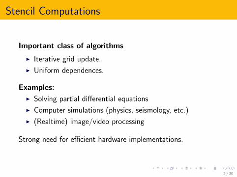
Stencil Computations
Important class of algorithms
I Iterative grid update.
I Uniform dependences.
Examples:
I Solving partial differential equations
I Computer simulations (physics, seismology, etc.)
I (Realtime) image/video processing
Strong need for efficient hardware implementations.
2 / 30

Application Domains
Two main application types with vastly 6= goals:
HPC
I “Be as fast as possible”
I No realtime constraints
Embedded Systems
I “Be fast enough”
I Realtime constraints
For now, we focus on FPGAs from the HPC perspective.
3 / 30

FPGA As Stencil Accelerators ?
CPU: ≈ 10 cores
Cache
Control ALUs
DDR
≈ 10GB/s
GPU: ≈ 100 cores
GDDR
≈ 100GB/s
FPGA: ≈ 1000 cores
DDR
≈ 1GB/s
Features:
I Large on-chip bandwidth
I Fine-grained pipelining
I Customizable datapath /arithmetic
Drawbacks:
I Small off-chip bandwidth
I Difficult to program
I Lower clock frequencies
4 / 30

Design Challenges
At least two problems:
I Increase throughput with parallelization.Examples:
I Multiple PEs.I Pipelining.
I Decrease bandwidth occupationI Use onchip memory to maximize reuseI Choose memory mapping carefully to enable burst
accesses
5 / 30

Stencils “Done Right” for FPGAs
Observation:
I Many different strategies exist:I Multiple-level tilingI Deep pipeliningI Time skewingI . . .
I No papers put them all together.
Key features:
I Target one large deeply pipelined PE...I ...instead of many small PEs
I Manage throughput/bandwidth with two-level tiling
6 / 30

Multiple-Level Tiling
Composition of 2+ tiling transformations to account for:
I Memory hierarchies and localityI Register, caches, RAM, disks, . . .
I Multiple level of parallelismI Instruction-Level, Thread-Level, . . .
In this work:
1. Inner tiling level: parallelism.
2. Outer tiling level: communication.
7 / 30

Overview of Our Approach
Core ideas:
1. Execute inner, Datapath-Level tiles on a single,pipelined “macro-operator”.
I Fire a new tile execution each cycle.I Delegate operator pipelining to HLS.
2. Group DL-tiles into Communication-Level Tiles todecrease bandwidth requirements.
I Store intermediary results on chip.
8 / 30

Outline
Introduction
Approach
Evaluation
Related Work and Comparison
Future Work & Conclusion
9 / 30

Running Example: Jacobi (3-point, 1D-data)
Simplified code:
f o r ( t =1; t<T ; t++)f o r ( x =1; x<N−1; x++)
f [ t ] [ x ] = ( f [ t −1] [ x−1] + f [ t −1] [ x ] + f [ t −1] [ x + 1 ] ) / 3 ;
Dependence vectors:
(−1,−1), (−1, 0), (−1, 1)
10 / 30

Datapath-Level Tiling
t
x
t
x
t, x 7→ t, x + t
11 / 30

Datapath-Level Tiling
t
x
t
x
t, x 7→ t, x + t
11 / 30

Datapath-Level Tiling
t
x
t
x
t, x 7→ t, x + t
11 / 30

Datapath-Level Tile Operator
f o r ( t = . . . ) {#pragma HLS PIPELINE I I =1f o r ( x = . . . ) {
#pragma HLS UNROLLf o r ( t t = . . . ) {
#pragma HLS UNROLLf o r ( xx = . . . ) {
i n t t = t+t t , x = x+xx−t ;f [ t ] [ x ] =
( f [ t −1] [ x −1] + f [ t −1] [ x ] + f [ t −1] [ x + 1 ] ) / 3 ;}
}
}}
Types of parallelism:
I Operation-Level parallelism (exposed by unrolling).
I Temporal parallelism (through pipelined tile executions).
12 / 30

Pipelined Execution
Pipelined execution requires inter-tile parallelism.
Original dependences Tile-level dependences
Gauss-Seidel dependences
13 / 30

Wavefronts of Datapath-Level Tiles
Skewing: t, x 7→ t + x , xWavefronts
14 / 30

Wavefronts of Datapath-Level Tiles
Skewing: t, x 7→ t + x , x
Wavefronts
14 / 30

Wavefronts of Datapath-Level Tiles
Skewing: t, x 7→ t + x , x
Wavefronts
14 / 30

Managing Compute/IO Ratio
Problem
Suppose direct pipelining of 2× 2 DL-tiles.At each clock cycle:
I A new tile enters the pipeline.
I Six 32-bit values are fetched from off-chip memory.
At 100 MHz, bandwidth usage are 19.2 GBps !
Solution
Use a second tiling level to decrease bandwidthrequirements.
15 / 30

Communication-Level Tiling
1
2
3
4
WF1 WF2
d2
d1
d1 = d2
≥ d
Shape constraints:
I Constant-height wavefrontsI Enables use of simple FIFOs
for intermediary results
Size constraints:
I Tiles per WF ≥ pipeline depth
I BW requirements ≤ chip limit
I Size of FIFOs ≤ chip limit
0 1 2 3 4 5 6
d = 4
16 / 30

Communication-Level Tiling
1
2
3
4
WF1 WF2
d2
d1
d1 = d2
≥ d
Shape constraints:I Constant-height wavefronts
I Enables use of simple FIFOsfor intermediary results
Size constraints:
I Tiles per WF ≥ pipeline depth
I BW requirements ≤ chip limit
I Size of FIFOs ≤ chip limit
0 1 2 3 4 5 6
d = 4
16 / 30

Communication-Level Tile Shape
Hyperparallelepipedic (rectangular) tiles satisfy all shapeconstraints.
skew−1
17 / 30

Communication
Two aspects:
On-chip Communication
I Between DL-tiles
I Uses FIFOs
Off-chip Communication
I Between CL-tiles
I Uses memory accesses
18 / 30

On-Chip Communication
We use Canonic Multi-Projections(Yuki and Rajopadhye, 2011).
Main ideas:
I Communicate along canonicalaxes.
I Project diagonal dependences oncanonical directions.
I Some values are redundantly stored. buff
t(i
n)
buff x (in)
buff
t(o
ut)
buff x (out)
19 / 30

Off-Chip Communication
Between CL-Tiles (assuming lexicographic ordering):
I Data can be reused along the innermost dimension.
I Data from/to other tiles must be fetched/stored off-chip.
I Complex shape
I Key for performance: use burstaccesses
I Maximize contiguity with clevermemory mapping
20 / 30

Off-Chip Communication
Between CL-Tiles (assuming lexicographic ordering):
I Data can be reused along the innermost dimension.
I Data from/to other tiles must be fetched/stored off-chip.
I Complex shape
I Key for performance: use burstaccesses
I Maximize contiguity with clevermemory mapping
20 / 30

Outline
Introduction
Approach
Evaluation
Related Work and Comparison
Future Work & Conclusion
21 / 30

Metrics
I Hardware-related metricsI Macro-operator pipeline depthI Area (slices, BRAM & DSP)
I Performance-related metrics (at steady state)I ThroughputI Required bandwidth
22 / 30

Preliminary Results: Parallelism scalability
2×2 2×4 4×2 4×4 8×8 2×2×2 3×3×3 4×4×4
3.4
GF
Lo
p/
s
5.8
GF
Lo
p/
s
5.8
GF
Lo
p/
s
11.5
GF
Lo
p/
s 28.2
GF
Lo
p/
s
7.2
GF
Lo
p/
s 20.3
GF
Lo
p/
s
38.4
GF
Lo
p/
s
2% 5
%
9%
8%
34
%
13
%
21
%
44
%
61
61
11
7
11
7
22
9
10
0
14
8
19
6
Datapath-level tile size
Ste
ady-
Sta
teth
rou
ghp
ut
Com
pu
tati
onre
sou
rce
usa
geP
ipel
ine
dep
th
Choose DL-tile to control:
I Computational throughput
I Computational resource usage
I Macro-operator latency and pipeline depth23 / 30
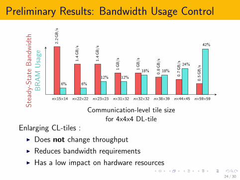
Preliminary Results: Bandwidth Usage Control
n×15×14 n×22×22 n×23×23 n×31×32 n×32×32 n×38×39 n×44×45 n×59×59
2.2
GB
/s
1.4
GB
/s
1.4
GB
/s
1G
B/
s
1G
B/
s
0.8
GB
/s
0.7
GB
/s
0.5
GB
/s
6% 6%
12% 12%
18% 18%
24%
42%
Communication-level tile sizefor 4x4x4 DL-tile
Ste
ady-
Sta
teB
and
wid
thB
RA
MU
sage
Enlarging CL-tiles :
I Does not change throughput
I Reduces bandwidth requirements
I Has a low impact on hardware resources
24 / 30

Outline
Introduction
Approach
Evaluation
Related Work and Comparison
Future Work & Conclusion
25 / 30

Related Work
I Hardware implementations:I Many ad-hoc / naive architecturesI Systolic architectures (LSGP)I PolyOpt/HLS (Pouchet et al., 2013)
I Tiling to control compute/IO balanceI Alias et al., 2012
I Single, pipelined operatorI Innermost loop body only
I Tiling method:I “Jagged Tiling” (Shrestha et al., 2015)
26 / 30

Outline
Introduction
Approach
Evaluation
Related Work and Comparison
Future Work & Conclusion
27 / 30

Future Work
I Finalize implementation
I Beyond Jacobi
I Exploring other number representations:I Fixed-pointI Block floating-pointI Custom floating-point
I Hardware/software codesign
I . . .
28 / 30

Conclusion
I Design template for FPGA stencil accelerators
I Two levels of control:I ThroughputI Bandwidth requirements
I Maximize use of pipeline parallelism
29 / 30

Thank You
Questions ?
30 / 30