Towards Run-time Assurance of Advanced Propulsion Algorithms€¦ · Advanced Propulsion Algorithms...
24
National Aeronautics and Space Administration Run-time Assurance for Advanced Propulsion Algorithms 5th NASA GRC Propulsion Control and Diagnostics Workshop September 16-17, 2015 Edmond Wong NASA Glenn Research Center Cleveland, OH Amy Chicatelli Vantage Partners, LLC Brook Park, OH John Schierman Thomas Schlapkohl Barron Associates, Inc. Charlottesville, VA
-
Upload
phunghuong -
Category
Documents
-
view
233 -
download
0
Transcript of Towards Run-time Assurance of Advanced Propulsion Algorithms€¦ · Advanced Propulsion Algorithms...

National Aeronautics and Space Administration
Run-time Assurance for Advanced Propulsion Algorithms
5th NASA GRC Propulsion Control and Diagnostics WorkshopSeptember 16-17, 2015
Edmond WongNASA Glenn Research Center
Cleveland, OH
Amy ChicatelliVantage Partners, LLC
Brook Park, OH
John SchiermanThomas Schlapkohl
Barron Associates, Inc.Charlottesville, VA

National Aeronautics and Space Administration
Outline
2
Motivation & Background
Run-Time Verification Overview
Case Study
Experiment Results
Conclusion
Future Work

National Aeronautics and Space Administration
Motivation & Background
3

National Aeronautics and Space Administration
Motivation: Advanced Propulsion Algorithms
Safety and performance goals for next-gen aircraft have driven the development of increasingly advanced engine control and health management algorithms:
• Intelligent and autonomous
• Adaptive, onboard learning, self-tuning and reconfigurable
Potential to enable:
• Increased performance
• Autonomous adaptation to accommodate:
– Damage and wear
– Hardware faults (sensors & effectors)
– Uncertain environmental conditions
Emerging approach at NASA and industry partners:
• Real-time onboard models
– Enable estimation of unmeasured engine parameters
– Enable estimation-based control
– Facilitate onboard diagnostic
4

National Aeronautics and Space Administration
Motivation: Certification Challenge
Deployment of advanced algorithms require certification to achieve high confidence in their safety. • Becoming increasingly difficult and cost-prohibitive using current
verification & validation (V&V) practices
• Complete V&V at design-time for some algorithms may not be feasible
– Non-determinism or complexity preclude exhaustive testing
– As a result, complete coverage cannot be achieved
Problem being addressed• Advancements in design-time analysis (formal methods) to provide
mathematical proof of the safe execution of highly complex systems.
• Advancements in run-time verification – using monitors to observe execution of uncertified algorithms to insure system behavior remains constrained within acceptable bounds of stability.
5

National Aeronautics and Space Administration
Run-Time Verification
6

National Aeronautics and Space Administration
Run-Time Verification Overview
An analysis approach from computer science• Monitors observe execution of a running system (i.e. software program) to
detect whether behavior satisfies or violates correctness properties.
• Used to augment design-time model checking of high-level language programs.
Application of run-time monitoring to real-time software. • Real-time execution enables (upon detection of property violation):
– Remedial action (e.g. provide an alert, influence subsequent execution) or
– Enforcement of an expected behavior to avoid violations.
Recent research investigates application to:• Verification of embedded systems (tightly coupled software/hardware)
• Safety-critical systems
• Run-time assurance of flight-critical system
• NASA interest in run-time assurance for advanced engine algorithms
7
National Aeronautics and Space Administration
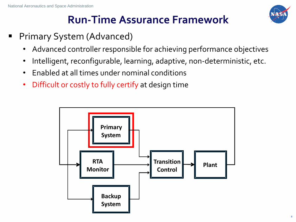
Run-Time Assurance Framework
Primary System (Advanced)• Advanced controller responsible for achieving performance objectives
• Intelligent, reconfigurable, learning, adaptive, non-deterministic, etc.
• Enabled at all times under nominal conditions
• Difficult or costly to fully certify at design time
8
PrimarySystem
RTAMonitor
BackupSystem
PlantTransitionControl

National Aeronautics and Space Administration
Run-Time Assurance Framework
Backup System (Fail-Safe)• Simplified control system with emphasis on safety rather than performance
• Does not possess advanced elements that cannot be certified
• Certified at design-time using traditional methods
9
PrimarySystem
RTAMonitor
BackupSystem
PlantTransitionControl

National Aeronautics and Space Administration
Run-Time Assurance Framework
RTA Monitor & Transition Control • Continually monitor overall state of the system
• Compare against validated representation of safe operating envelope
• If violation occurs, Transition Controller disables Advanced System and transfers control to Backup System
• Must be certified at design time
10
PrimarySystem
RTAMonitor
BackupSystem
PlantTransitionControl

National Aeronautics and Space Administration
RTA Implementation Issues
What should be monitored?• All states & critical parameters that affect safety of the system
– Safety limits (structural limits, component limits)
– Operational limits
– Performance limits
How should the switching conditions be defined?• When should the switch be activated? How much margin needed?
– Switch too late – safety could be compromised
– Switch too early – performance of advanced system could be limited
11

National Aeronautics and Space Administration
Case Study: Model-Based Engine Control
12

National Aeronautics and Space Administration
Case Study: Model-Based Engine Control
Investigate application of RTA approach to GRC’s Model-Based Engine Control
13
PrimarySystem
RTAMonitor
BackupSystem
PlantTransitionControl
Traditional EPR Controller – similar to certified controllers
Model-Based Engine Control (MBEC)
Simple Switch
Commercial Modular Aero-Propulsion System Simulation 40k (C-MAPSS40k)

National Aeronautics and Space Administration
RTA Integrated with Engine Control
Integrated in a simulation platform under MATLAB/Simulink
RTA outputs inRAE flag to select control mode
• inRAE = 1 => true => no parameter has violated its limit
• inRAE = 0 => false => at least one parameter has violated its limit
Transition Control performs simple switching between the advanced thrust based controller and the backup EPR controller
Switching the type of stall margin limiter14
Thrust Controller/SM Controller
RTAMonitor
EPR Controller/Accel. Schedule
ProtectionLogic
Sensed Parameters
Actuator Engine
EstimationOTKF
MBEC
Backup System
Fnet
EPR
inRAE
HPC-SM
TransitionControl
Primary System
Simple Switching

National Aeronautics and Space Administration
Monitored States
Defining Safety Boundaries for this initial study• Monitored well-understood
engine safety & operational limits
• Monitored analytical parameters: Kalman filter residuals to assess performance
15
Limited Parameter Value
Safety and Operational Limits
Fan Speed (Nf) max = 4200 rpm
Core Speed (Nc) max=12200 rpm
HPC discharge pressure (Ps3) max = 433 psi
HPC stall margin (smHPC) min = 8%
LPC stall margin (smLPC) min = 6%
RU limit min = 17%
Kalman Filter Residual Limits (% error)
Fan speed (Nf) max = 3%
Core speed (Nc) max = 3%
HPC discharge temperature (T30) max = 3%
LPT discharge temperature (T50) max = 3%
HPC discharge pressure (Ps3) max = 3%
LPT exit pressure (P50) max = 3%
3
Ratio Unit Limit = f
S
w
P

National Aeronautics and Space Administration
Experimental Results
16

National Aeronautics and Space Administration
Nominal Experimental Results Nominal Take-off
• PLA increased: 43 to 80 deg. over 5 sec. Initial conditions: Mach 0, altitude 0 ft.
• RTA maintains operation with Model-based Engine Controller
17
RTA Output Flag
Thrust (Truth)
HPC Static Discharge Pressure
Combustor Exit Temperature

National Aeronautics and Space Administration
Nominal Experimental Results Nominal Cruise
• PLA increased: 60 to 70 deg. over 5 sec. Initial conditions: Mach 0.7, altitude 30K ft.
• RTA maintains operation with Model-based Engine Controller
18
RTA Output Flag
Thrust (Truth)
HPC Static Discharge Pressure
Combustor Exit Temperature

National Aeronautics and Space Administration
Seeded error within the OTKF
• Created sign errors in simulation (e.g. Δy and DΔu terms)
• Result in:
– Incorrect estimates
– Poor performance
– Issues with protection logic
19
Induced OTKF Fault Experiment
Operating conditions:
• Take-off profile
– PLA linearly increased: 43 to 80 deg. over 5 second period
– Initial conditions: Mach 0, altitude 0 ft.
• Cruise operating condition
– PLA linearly increased: 60 to 70 deg. over a 5 second period
– Initial conditions: Mach 0.7, altitude 30K ft.

National Aeronautics and Space Administration
Induced OTKF Fault Experiment Seeded error: Δy coding error (sign error) introduced @ t = 20 sec during take-off
• RTA switches to EPR controller @ t = 22 sec KF residuals exceed their limits
• Ps3 reaches safety limit. Protection Logic overrides controller
20
Ps3 reach safety limit. Protection logic overrides controller.
Error initialized at t=20s
KF residuals exceed limits
RTA Output Flag
Thrust (Truth)
HPC Static Discharge Pressure
Combustor Exit Temperature

National Aeronautics and Space Administration
Seeded error: Δy coding error introduced @ t = 20 sec during cruise
• RTA switches to EPR controller @ t = 22 sec KF residuals exceed their limits
• Alternating control from protection logic elements: RU min. limiter & HPC SM max. limiter
21
Error initialized at t=20s
KF residuals exceed limits
RTA Output Flag
Thrust (Truth)
Ratio Unit (Wf/Ps3) Deccelerator Limit
HPC Stall Margin (Truth)
Induced OTKF Fault Experiment

National Aeronautics and Space Administration
Conclusion
Provided motivation for pursuit of run-time assurance as a potential means to address certification barrier for advanced propulsion algorithms.
An overview of run-time monitoring methods was presented.
A case study was initiated to investigate the feasibility of RTA approach to propulsion control.
An RTA framework was developed and integrated with NASA’s Model-Based Engine Control (MBEC) architecture
Preliminary experiments and results.
22

National Aeronautics and Space Administration
23
Future Work
Current:
• Develop more robust transition logic to replace the simple switching. Ensure stable transition from the advanced controller to the backup controller.
• Investigate more sophisticated approaches to determination of safety envelope. In addition to current safety, operational & performance limits/conditions.
Long-term:
• Investigate a generalized RTA framework for propulsion control monitoring, assurance and assessment.
• Applicable to other advanced algorithms
• Scalable to a variety of propulsion types.
• Engage certification authorities to work towards acceptance of approach.
National Aeronautics and Space Administration
24
References
Wong, E., Schierman, J., Schlaphohl, T., and Chicatelli, A., “Towards Run-time Assurance of Advanced Propulsion Algorithms,” 50th AIAA/ASME/SAE/ASEE Joint Propulsion Conference,” No. AIAA 2014-3636, 2014.
Connolly, J., Csank, J., Chicatelli, A., Kilver, J., “Model-Based Control of a Nonlinear Aircraft Engine Simulation using an Optimal Tuner Kalman Filter Approach,” 49th
AIAA/ASME/SAE/ASEE Joint Propulsion Conference,” No. AIAA 2013-4002, 2013.
Connolly, J., Chicatelli, A., and Garg, S., “Model-Based Control of an Aircraft Engine using an Optimal Tuner Approach,” 48th AIAA/ASME/SAE/ASEE Joint Propulsion Conference, No. AIAA 2012-4257, 2012.
Simon, D. L., “An Integrated Architecture for On-Board Aircraft Engine Performance Trend Monitoring and Gas Path Fault Diagnostics. NASA TM 216358, 2010.
Csank, J., Ryan, M., Litt, J. S., and Guo, T., "Control Design for a Generic Commercial Aircraft Engine," Technical Report NASA/TM 2010-216811, 2010.
May, R., Csank, J., Litt, J. S., and Guo, T., "Commercial Modular Aero-Propulsion System Simulation 40K," Technical Report NASA/TM 2010-216810, NASA, 2009.