
TOWARDS COLLECTIVE ROBOTICS IN A 3D …mdorigo/HomePageDorigo/thesis/dea/PiniMAS.pdf · ing...
65
UNIVERSIT ´ E LIBRE DE BRUXELLES Facult´ e des Sciences Appliqu´ ees CODE - Computers and Decision Engineering IRIDIA - Institut de Recherches Interdisciplinaires et de D´ eveloppements en Intelligence Artificielle TOWARDS COLLECTIVE ROBOTICS IN A 3D SPACE: SIMULATION WITH HAND-BOT ROBOTS Giovanni PINI Supervisor: Prof. Marco DORIGO Co-supervisor: Dr. Mauro BIRATTARI Rapport d’avancement de recherche Academic year: 2008-2009
Transcript of TOWARDS COLLECTIVE ROBOTICS IN A 3D …mdorigo/HomePageDorigo/thesis/dea/PiniMAS.pdf · ing...

UNIVERSITE LIBRE DE BRUXELLES
Faculte des Sciences Appliquees
CODE - Computers and Decision Engineering
IRIDIA - Institut de Recherches Interdisciplinaires
et de Developpements en Intelligence Artificielle
TOWARDS COLLECTIVE ROBOTICS IN A 3D
SPACE: SIMULATION WITH HAND-BOT
ROBOTS
Giovanni PINI
Supervisor:Prof. Marco DORIGO
Co-supervisor:Dr. Mauro BIRATTARI
Rapport d’avancement de rechercheAcademic year: 2008-2009


Summary
The goal of the research work presented in this report is to show that cooperation can
overcome individual limitations in execution of tasks in a 3D environment.
Works in robotics have shown that cooperative systems can perform tasks a single
robot cannot. My research work is to investigate the extent at which cooperation can
be exploited in tasks that develop in the third dimension, showing its benefits for the
robotic system. This dissertation reports the preliminary steps towards this goal.
The robotic platform used for the experiments is the hand-bot robot. The hand-
bot is one of the three robots that will compose the robotic swarm of the Swarmanoid
project, a project funded by the European Commission. The hand-bot is a robot
that joins manipulation capabilities with the possibility of moving on a vertical plane.
Therefore, it is the natural candidate to be used for carrying out my studies.
I modeled the robot, its sensors and actuators, using the Open Dynamics Engine
(ODE), and have been embedded into the Swarmanoid simulator, a custom software
written in C++. The model is therefore available as a project-wide tool, that can be
used by all the people involved in Swarmanoid.
At the current project stage, the robots are still under development. The exper-
iments presented in Chapter 4 have been carried out using the simulated model of
the robot. The simulations confirm the fact that cooperation enhances the system’s
capabilities by overcoming individual limitations. The controllers developed using the
simulator can be transferred to real robots without any modification as soon as the
hardware is available.
3

Acknowledgments
I would like to thank Prof. Marco Dorigo for his supervision and for giving me the
opportunity of working at IRIDIA, first as a master student and now as a PhD stu-
dent. Working at IRIDIA is a pleasure, as it is an extremely friendly and stimulating
research environment.
Furthermore, I thank Mauro for his support and his advices in my everyday work.
I also thank all the IRIDIA colleagues (in office-based order): Carlo, Ali, Eliseo, Marco,
Antal, Arnucci, Nithin, Matteo, Rehan, Manuele, Francesco, Jeremie, Colin, Alex,
Francisco, Sven, Paolo, Saifullah, Prasanna, Eric, Sabrina, Manuel, Matteo, Thomas,
Renaud.
To conclude, I thank my family for supporting me, and Silvia for her love.
5

6

Contents
Contents 6
List of Figures 8
1 Introduction 11
2 Swarmanoid 15
2.1 Foot-bot hardware . . . . . . . . . . . . . . . . . . . . . . . . . . . . . 16
2.2 Eye-bot hardware . . . . . . . . . . . . . . . . . . . . . . . . . . . . . . 17
2.3 Hand-bot hardware . . . . . . . . . . . . . . . . . . . . . . . . . . . . . 19
3 ARGoS 27
3.1 ODE model . . . . . . . . . . . . . . . . . . . . . . . . . . . . . . . . . 29
3.2 Implemented actuators . . . . . . . . . . . . . . . . . . . . . . . . . . . 32
3.3 Implemented sensors . . . . . . . . . . . . . . . . . . . . . . . . . . . . 35
4 Experiments 39
4.1 Grasping simple objects . . . . . . . . . . . . . . . . . . . . . . . . . . 40
4.2 Lifting a bar . . . . . . . . . . . . . . . . . . . . . . . . . . . . . . . . . 44
4.3 Random exploration of vertical plane . . . . . . . . . . . . . . . . . . . 49
5 Work in progress 55
5.1 Heavy bar lift . . . . . . . . . . . . . . . . . . . . . . . . . . . . . . . . 55
5.2 Heavy board lift . . . . . . . . . . . . . . . . . . . . . . . . . . . . . . . 58
6 Conclusions and future work 61
Bibliography 63
7

8

List of Figures
2.1 Foot-bot CAD model . . . . . . . . . . . . . . . . . . . . . . . . . . . . 17
2.2 Eye-bot prototype . . . . . . . . . . . . . . . . . . . . . . . . . . . . . . 18
2.3 Hand-bot CAD model . . . . . . . . . . . . . . . . . . . . . . . . . . . 19
2.4 Rope launcher CAD model . . . . . . . . . . . . . . . . . . . . . . . . . 21
2.5 LED ring and foot-bot’s gripper . . . . . . . . . . . . . . . . . . . . . . 22
2.6 Hand-bot’s IR proximity sensors . . . . . . . . . . . . . . . . . . . . . . 23
2.7 Hand-bot’s IR proximity sensors . . . . . . . . . . . . . . . . . . . . . . 24
2.8 Hand-bot’s IR proximity sensors . . . . . . . . . . . . . . . . . . . . . . 25
3.1 Simulator architecture . . . . . . . . . . . . . . . . . . . . . . . . . . . 28
3.2 ODE model of the hand-bot . . . . . . . . . . . . . . . . . . . . . . . . 30
3.3 ODE joints . . . . . . . . . . . . . . . . . . . . . . . . . . . . . . . . . 31
3.4 Rope implementation in ODE . . . . . . . . . . . . . . . . . . . . . . . 34
3.5 Rope implementation in ODE . . . . . . . . . . . . . . . . . . . . . . . 37
4.1 Object grasping: experimental setup . . . . . . . . . . . . . . . . . . . 40
4.2 Object grasping: controller FSM . . . . . . . . . . . . . . . . . . . . . . 41
4.3 Object grasping: sequence of movements . . . . . . . . . . . . . . . . . 42
4.4 Light bar lift, strategies and situations . . . . . . . . . . . . . . . . . . 44
4.5 Bar lift: experimental setup . . . . . . . . . . . . . . . . . . . . . . . . 45
4.6 Bar lift: results . . . . . . . . . . . . . . . . . . . . . . . . . . . . . . . 47
4.7 Vertical plane exploration: sequence using one hand-bot . . . . . . . . 49
4.8 Vertical plane exploration: working principle . . . . . . . . . . . . . . . 50
4.9 Vertical plane exploration: experimental setup . . . . . . . . . . . . . . 51
4.10 Vertical plane exploration: experimental setup . . . . . . . . . . . . . . 53
4.11 LED ring and foot-bot’s gripper . . . . . . . . . . . . . . . . . . . . . . 54
5.1 Starting setup for the heavy bar lift experiment . . . . . . . . . . . . . 56
5.2 Heavy object lift: controller FSM . . . . . . . . . . . . . . . . . . . . . 56
5.3 Heavy board lift: experimental setup . . . . . . . . . . . . . . . . . . . 59
9

10

Chapter 1
Introduction
This work reports the first experimental results of a research in collective robotics. The
subject of the research is the study of cooperation as a mean of overcoming individual
limitations in the execution of tasks that mainly develop in the third dimension.
Garnier et al. (2007) provide a definition of the term “cooperation”:
“Cooperation occurs when individuals achieve together a task that could not
be done by a single one. The individuals must combine their efforts in order
to successfully solve a problem that goes beyond their individuals abilities.”
Kube & Zhang (1993) introduce a similar idea:
“Non-cooperative tasks gain efficiency in execution due to parallel divide-
and-conquer approach, but can be accomplished by a single robot given
enough time [. . . ] On the other hand, cooperative tasks cannot be accom-
plished by a single robot and require the cooperative behavior of several
machines working together.”
The experiments described at the end of this dissertation, and the ongoing research
have been conducted bearing in mind these definitions. The stress is on the fact that
a single individual cannot perform the task alone. The study of cooperative systems
is not only interesting at the theoretical level, but the enhancement of the systems
capabilities through cooperation can also be exploited in the practice: the agents can
be kept simple and cooperation can lead to complex behaviors.
A particular attention is given to swarm-robotics (see Bonabeau et al. 1999, Beni 2004,
for a review), a discipline that consists in the application of swarm-intelligence princi-
ples in the implementation of collective robotics systems. Swarm-intelligence is a branch
of artificial-intelligence that draws inspiration from biological systems (Bonabeau et al.
11

2000, Garnier et al. 2007). Swarm-intelligence systems are typically made up of a popu-
lation of simple agents interacting locally with one another and with their environment.
The agents follow very simple rules, and there is no centralized control structure dictat-
ing how individual agents should behave. Nevertheless, local, and to a certain degree
random, interactions between such agents lead to the emergence of “intelligent” global
behavior, which is not encoded into the individual agents.
Natural examples of SI include ant colonies (Detrain & Deneubourg 2006), bird flock-
ing (Reynolds 1987), animal herding (Gautrais et al. 2007), colony of bacteria (Ben-
Jacob et al. 2000), and fish schooling (Grunbaum et al. 2004).
Following the swarm-intelligence approach normally leads to the development of
systems that are flexible, robust, adaptive and scalable (Camazine et al. 2003, Cao
et al. 1997). Those properties motivate the growing research interest in this field, dur-
ing the last years. The research works led to the application in different domains, that
range from optimisation (Dorigo & Stutzle 2004) to robotics. In case swarm-intelligence
principles are applied to the development of robotic systems, we speak about swarm-
robotics.
A swarm of robots is made up of a set of simple robots whose interaction leads to
complex collective behaviors. Swarm-robotics aims at building swarms of small-scale
and simple robots able to collectively accomplish tasks such as exploration, object
transportation, foraging and structure building, taking inspiration from social insects.
No robot in the swarm has a global knowledge of the environment or of the status of the
swarm itself. Instead, each robot exploits only local information and a global behavior
emerges from the interactions among the individuals.
The main advantages of using the swarm-robotics approach are:
• It allows miniaturization of the robots, complex behaviors derives from interaction
rather than being performed by complex agents;
• Flexibility, adaptability and robustness help coping with uncertainty;
• Low unit cost allows redundancy which, in turn, improves fault tolerance;
Those qualities made the swarm-robotics approach increasingly studied and investi-
gated in the last years. Futuristic application such as nanorobotics require tiny robots,
with limited capabilities. To be effective such robots need to cooperate in order to
exhibit meaningful behaviors.
Flexibility, adaptability, robustness, and low cost are suitable for those situations with
high uncertainty such as space exploration, where the environment is not well known
12

and potentially dangerous for the robots.
Nowadays swarm-robotics research concerns different kinds of tasks: self deploy-
ment, foraging, coordinated movement, self-assembly, aggregation, pattern formation
(see Bayindir & Sahin (2007) for a review). In the last years, studies and solutions to
these problems produced a wide literature. Even if they present different challenges
and highlight different properties, these tasks have a common trait: they can all be
considered two dimensional tasks, in the sense that they mainly develop on a the hor-
izontal plane. In our eyes, the application of swarm-robotics principles in tasks that
develop in a three dimensional environment has not received much attention in the
literature. The vertical dimension adds real time and dynamical requirements that are
negligible in two dimensional tasks. The goal of our research is to move the first steps
toward understanding whether swarm-robotics principles still hold in this kind of tasks.
Some steps have already been moved toward this direction. Ahmadabadi & Eiji
(2001) study the problem of lifting and transporting an object by a group of robots.
The object is moved along the floor, but since it has to be kept lifted, it is introduced
a third dimensional component critical for the group’s success. A similar work is pre-
sented in (Sugar & Kumar 2002): the authors address the coordination of three mobile
manipulators that cooperatively grasp a large, flexible object and transport it in an
environment with obstacles.
Those are, to the best of our knowledge, the works that exploit robot collaboration in
the three dimensions. In other works concerning object transportation (for example
J. Fink 2008), the transported item slides on the ground, thus the task does not really
develop in three dimensions.
The interest in tasks that develop in three dimensions comes from the fact that they
appear in a wide range of robotic applications. Typical applications of industrial robots
include welding, painting, ironing, assembly, pick and place, packaging and palletizing,
product inspection. All these tasks are inherently three dimensional and they are usu-
ally performed using a single robot. The vision at the base of my work is to employ
swarm of robots in tasks of this kind, to benefit from swarm-robotics properties of
robustness, flexibility and low cost.
In the following chapters we present the preliminary work done towards the study of
swarm-robotics in task that develop in the third dimension. Chapter 2 gives an overview
of the Swarmanoid project, a project funded by the European Commission, whose goal
is the development of an innovative distributed system composed of heterogeneous
robots. One of the robotic platforms that compose such a system has been used to
13

carry on the studies presented in this report.
Chapter 3 describes ARGoS : a multi-robot, multi-physics engine and highly modular
simulator, that has been developed specifically for Swarmanoid fitting the project’s
requirements.
Chapter 4 describes the first experiments and their results. The experiments have been
run using the ARGoS simulator, since the robots are still under development at the
moment of writing this document. Nevertheless, the simulator is designed to allow a
seamless transfer of the controllers to the real robots.
Chapter 5 describes the work that is currently being carried out.
Finally chapter 6 summarizes the main achievements of the work presented here, and
outlines future directions of the research.
14

Chapter 2
Swarmanoid
The research work presented in this dissertation has been carried out in the context of
the Swarmanoid project. Swarmanoid is a Future and Emerging Technologies (FET-
OPEN)1 project funded by the European Commission. The project, following and
extending the Swarm-bots project (see Dorigo et al. (2005), Mondada et al. (2004)
for a review), involves five European partners: CNR-ITSC (Consiglio Nazionale delle
Ricerche, Roma, Italy), EPFL-LIS (Laboratory of Intelligent Systems, Ecole Polytech-
nique Federale de Lausanne, Switzerland), EPFL-LSRO (Institut de Production et
Robotique - Laboratoire de systemes robotiques, Ecole Polytechnique Federale de Lau-
sanne, Switzerland), IDSIA (Istituto Dalle Molle di Studi sull’Intelligenza Artificiale,
Lugano, Switzerland), IRIDIA-CoDE (ULB, Bruxelles).
The scientific goal of the Swarmanoid project is to propose a new way of design-
ing robotic systems that can live along with humans in human modified environments,
performing general purpose tasks. The project goal is pursued through the design,
implementation, and control of a novel distributed robotic system. The system will
be made up of heterogeneous, dynamically connected, small autonomous robots. The
organization of these heterogeneous robots in a swarm, yields to a “super entity” called
Swarmanoid, which gives the name to the project. Swarm-robotics approach has been
chosen because of its scalability, flexibility, and robustness properties.
Besides the development of the hardware platforms, Swarmanoid aims at studying
new control methodologies for the three types of robots. In the traditional methodol-
ogy, first a controller for a single robot is developed, then swarm behavior with similar
robots is inserted, and then finally interaction with the other types of robots is added.
We will avoid as much as possible this approach, favoring the opposite one. Since one of
1http://cordis.europa.eu/ist/fet/home.html
15

main points of interest of the project is the heterogeneity among robots, controllers for
the three families of robots are developed in parallel, so that the possible cooperative
issues are tackled and solved in a smoother and more natural way. Furthermore, many
interesting control issues are worth studying, such as the coordination of individual
local perception by the robots into a coherent representation of the environment, and
the study of mechanisms for adaptive task allocation in heterogeneous teams.
Another source of innovative challenges, which have never been addressed before, in-
volves the study of communication in an heterogeneous swarm of robots. For instance,
the emergence of communication in a robotic system in which hardware differences
plays a central role is a completely new question. Finally, also studying explicitly how
to efficiently share information among robots with so strongly different capabilities is
a novel issue considered in Swarmanoid.
To operate on human-oriented tasks we can identify three main capabilities a robotic
system must have: vision, manipulation, and locomotion. The “standard” robotics ap-
proach to this problem would make use of a complex robotic platform which embeds all
those capabilities. In Swarmanoid, the system is composed of a swarm of heterogeneous
robots of three kinds, each providing one of the mentioned capabilities. The robots in-
teract with each other to share abilities and complete their tasks. The three kind of
robots, composing the swarms are: foot-bot, eye-bot, and hand-bot. The following three
sections describe each of the robots. Since the hand-bot plays a central role in our
research, it is described at a higher level of detail than foot-bot and eye-bot.
2.1 Foot-bot hardware
The foot-bots (Fig. 2.1) are ground robots, whose design is based on the s-bot, the
robotic platform of the Swarm-bots project. Their basic capabilities are the same as in
the s-bot : they can move on the ground through a powerful treel drive and they can
connect to objects using a gripper2. Despite having the same functionalities of the s-
bot, the foot-bot represents a huge step forward with respect to its ancestor. The treels
motors are more powerful, allowing the robots to pull more weight. Hot swappable,
long-lasting, lithium polymer batteries do not require to stop the robot and connect
it to a recharging device, as with the s-bot. A super capacitor keeps the robot alive
while the battery is swapped, allowing for virtually limitless experiments. The camera
has been upgraded to 2.0 mega-pixels UXGA technology, with on-board image pre-
2This is possible only for some geometries
16
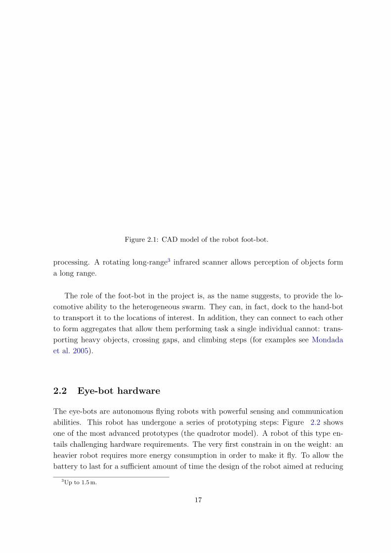
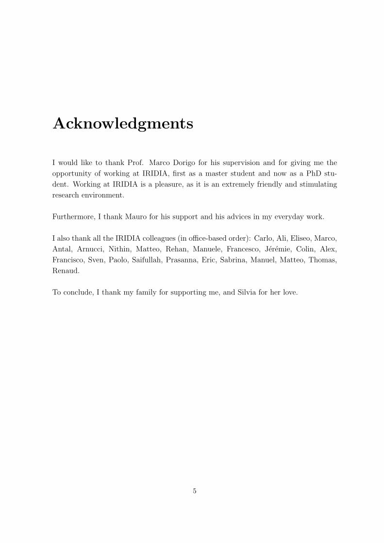
Figure 2.1: CAD model of the robot foot-bot.
processing. A rotating long-range3 infrared scanner allows perception of objects form
a long range.
The role of the foot-bot in the project is, as the name suggests, to provide the lo-
comotive ability to the heterogeneous swarm. They can, in fact, dock to the hand-bot
to transport it to the locations of interest. In addition, they can connect to each other
to form aggregates that allow them performing task a single individual cannot: trans-
porting heavy objects, crossing gaps, and climbing steps (for examples see Mondada
et al. 2005).
2.2 Eye-bot hardware
The eye-bots are autonomous flying robots with powerful sensing and communication
abilities. This robot has undergone a series of prototyping steps: Figure 2.2 shows
one of the most advanced prototypes (the quadrotor model). A robot of this type en-
tails challenging hardware requirements. The very first constrain in on the weight: an
heavier robot requires more energy consumption in order to make it fly. To allow the
battery to last for a sufficient amount of time the design of the robot aimed at reducing
3Up to 1.5 m.
17

Figure 2.2: Prototype of the robot eye-bot.
the weight. An additional requirement is on the payload: the more the robot can lift,
the richer the set of sensors can be. The actual prototype weights 400 g and can fly for
24 minutes with no payload or 15 minutes with a 116 g payload.
The eye-bot has also the ability to attach to a ferromagnetic ceiling by using a
magnet. This capability can be used to save energy: if needed, the robot can decide to
attach to the ceiling and stop its motors. From this privileged position, the robot can
still monitor the environment and communicate with the others, but it it not consum-
ing much energy.
The robot is equipped with Proportional-Integral-Derivative (PID) stability con-
trollers that run at 500 Hz, whose goal is to stabilize the platform during flight. Those
low level controllers can keep the robot flying in a certain position. However, due to
the inaccuracies in sensors and the dynamic environment the eye-bot will slowly drift
in a random direction if it is not provided with position correction information. An
optic-flow sensor, is under development in order to tackle this problem.
The eye-bot is equipped with a 2.0 mega pixel CMOS colour camera which resolu-
tion is adjustable through software using thus allowing for a digital zoom functionality.
The camera is capable of panning 360◦ in the horizontal plane and tilting 90◦ from
vertical to horizontal. This allows the visual scanning of the environment underneath
the robot. The same pan and tilt system is equipped with a laser pointer, which can
be used to focus attention of other robots on some specific locations.
18
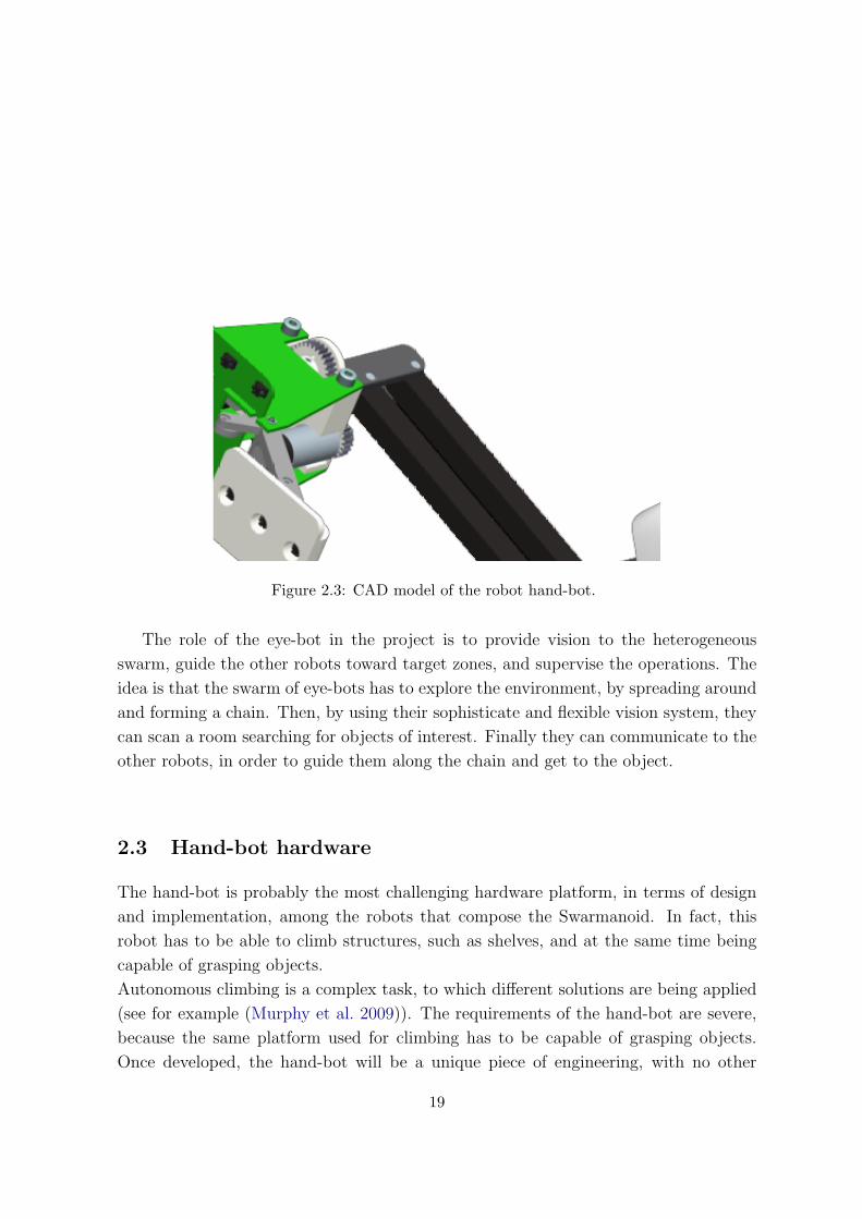
Figure 2.3: CAD model of the robot hand-bot.
The role of the eye-bot in the project is to provide vision to the heterogeneous
swarm, guide the other robots toward target zones, and supervise the operations. The
idea is that the swarm of eye-bots has to explore the environment, by spreading around
and forming a chain. Then, by using their sophisticate and flexible vision system, they
can scan a room searching for objects of interest. Finally they can communicate to the
other robots, in order to guide them along the chain and get to the object.
2.3 Hand-bot hardware
The hand-bot is probably the most challenging hardware platform, in terms of design
and implementation, among the robots that compose the Swarmanoid. In fact, this
robot has to be able to climb structures, such as shelves, and at the same time being
capable of grasping objects.
Autonomous climbing is a complex task, to which different solutions are being applied
(see for example (Murphy et al. 2009)). The requirements of the hand-bot are severe,
because the same platform used for climbing has to be capable of grasping objects.
Once developed, the hand-bot will be a unique piece of engineering, with no other
19
robotic platforms with similar characteristics.
In the context of Swarmanoid, the hand-bot role is to retrieve objects located on
shelves. The idea is that foot-bot connect to the hand-bot and take it at the bottom
of a shelf (as the hand-bot cannot move alone). Once there, the hand-bot is supposed
to climb the shelf to search for an object to be retrieved.
The hand-bot has been chosen as the tool to carry out our research in cooperative
robotics. The motivation behind this choice comes from the main characteristics of the
robot:
1. as part of a swarm, the robot’s capabilities are kept as simple as possible, this
is in accordance with swarm-intelligence philosophy, that demands interaction of
simple agents;
2. it has the capabilities to move and perform meaningful actions in a vertical direc-
tion, adding a three dimensional component in its tasks;
Thus, combining the two properties allows to study to which extent cooperation can
be exploited as a way of overcoming individual limitations in task that require acting
in a three dimensional space.
The control architecture of the hand-bot is shares a set of basic subsystems, common
to all robots. Having the same control architecture for all the robots facilitates the
hardware development and provides researchers with a coherent tool set to build their
controllers upon. The common set of capabilities comprises the following:
• the main processor board: the Freescale i.MX31 arm 11 processor, a low-energy
533 MHz processor with a complete collection of subsystems such as usb host
controller and integrated camera interface;
• the main core board built around the processor which provides 128 MB of ddr ram
and 32 MB of flash;
• a set of DsPIC 33 micro controllers for sensors and actuators;
• wireless communication in two fashions: WiFi, mainly intended for (relatively)
long range inter-robot communication, and Bluetooth, for basic robot setup and
short range inter-robot communication.
Concerning the actuators set of the robot, one of the main actuators of the hand-bot is
the rope launcher(see Fig. 2.4 on the right), that is used to shoot a rope, ending with
a magnet.
20

Figure 2.4: CAD model of the rope launcher, used by the hand-bot to shoot the rope andattach to magnetic ceilings. Left: rope launcher sectioned vertically. Right: external part ofthe rope launcher, including the cable rolling wheel.
The purpose of this actuator is to allow the hand-bot to attach with a rope to the ceil-
ing. This capability is mainly used to assist the robot during climbing: the hand-bot
climbs the shelves by attaching to them with its arms, but when performing this oper-
ation, it needs the rope in order to sustain the body weight and to assist the climbing
process.
The magnetic attach requires the ceiling to be ferromagnetic. This is a limitation
in the environmental setup the has been introduced in order to simplify the develop-
ment and the hardware requirements of the robot. This is an acceptable hypothesis,
considering that there are several studies which concern technologies that can make the
attach mechanism independent from the target (see for example (Murphy et al. 2009)).
The launcher works as follows: a strong motor loads the magnet by shrinking a
spring (see Fig. 2.4 left). When the spring is freed, it shoots the magnet vertically
and, at the same time, a fast motor unrolls the cable to follow the raising magnet. If
a ferromagnetic object is on the way, the magnet attaches. At that point the robot
can go up and down rolling and unrolling the rope, controlled by a strong motor. The
magnet is detached by a mechanism that turns it by 90◦, so that the magnetic field
becomes weaker with respect to the ceiling, and the magnet can be pulled out. When
the magnet is detached, the cable is rolled back by the fast motor to prevent the magnet
from hitting objects while falling.
An encoder allows to measure the length of the rope that is currently unrolled, this
21

Figure 2.5: LED ring and gripper. Left: LED ring lightened up in different colors. The LEDring is used for communication and robot detection through cameras. It also serves as dockingmechanism to allow robot assembly. Right: CAD model of the foot-bot gripper. The grippercan open and fit the LED ring shape, providing a connection point between different robots.
information can be used for precise4 height regulation.
Traction on the rope is measured through a torque sensor which monitors the torque
on the motor that rolls and unrolls the cable. This information can be used to avoid
dangerous overloads on the robot when trying to lift objects or, for example, to deduce
the weight of an object being lifted. While hanging, the orientation of the hand-bot’s
body along the three axis can be monitored by using a gyroscope.
As mentioned earlier, the hand-bot needs to be transported by the foot-bots in order
to reach the positions of interest. To allow this to happen, the hand-bot is equipped
with a ring (see Fig. 2.5 left) that allow the connections to take place. The foot-bot
is equipped with a gripper (see Fig. 2.5 right) that, when opened, fits the shape of the
ring and joins the two robots. The very same ring is present on the foot-bot, to allow
them to assemble with each other and form bigger structures.
Along the ring there are 12 LEDs (8 on the foot-bot), each of which can be lightened
up independently from the others. The LEDs can be used to make it easier to perceive
the robots by using cameras, as well as to communicate visually with the other robots
(see as examples (Nouyan et al. 2008, Christensen et al. 2007)).
Besides climbing on objects and assembling with foot-bots, the hand-bot has pow-
erful manipulation capabilities. Two strong arms, each with 4 rotational degrees of
freedom, provide the flexibility needed to grasp objects. The two arms can rotate with
4The error is estimated to be of the order of 1 mm
22

Figure 2.6: Front view of the hand-bot. The arms can rotate with respect to the body (seedashed arrows) and the grippers can rotate with respect to the arms (see continuous arrows).
respect to the body, as shown in Figure 2.6 (dashed arrows). The rotation of the arms
is not independent: they are forced to be always aligned.
In addition, the arms can open and close, along the direction shown by the continu-
ous arrows of Figure 2.7. In this case, each arm can be moved independently from the
other; during the movement the grippers keep always the same orientation, depicted in
the figure.
Concerning the grippers, they can be opened and closed, as shown in Figure 2.7 (con-
tinuous arrows), and they can rotate as shown by the dashed arrows of Figure 2.6.
The arms are not only used to manipulate objects, but they also assist the hand-bot
during climbing. In fact, while hanging from the rope, the hand-bot is not very stable
as it oscillates and spins. Grasping an object on a shelf requires the body to be as stable
as possible, as well as the arms to lean out towards the shelf. The robot can use its
23

Figure 2.7: Top view of the hand-bot. The arms can open and close along the path of thecontinuous arrow, the grippers can open and close along the path of the dashed arrows.
harms to grab the shelf while climbing, which maintains the body stable while going up.
Each motor inside the arms is equipped with encoders to measure the angular posi-
tions of the parts with a 0.1◦ precision. Through the encoders it is possible to measure:
the current orientation of the arms with respect to the body, the aperture of each arm,
the orientation of each gripper with respect to the arm, and the aperture of each grip-
per. These information can be used, if combined with the geometry of the robot, to
compute the Cartesian positions of each part with respect to the body.
Each gripper is provided with a set of twelve infrared proximity sensors (see Fig. 2.8).
The infrared sensors are intended to be used as “tactile” system for the robot: the
information coming from these sensors can be used by the hand-bot to perceive the po-
sition of the objects to be grasped, as well as to align to the shelves part while climbing.
The set of sensors is completed by three fish-eye 2 MegaPixels cameras with on-board
24

Figure 2.8: Depiction of IR proximity sensors inside the grippers. Those sensors help objectgrasping manoeuvres.
image pre-processing (such has edge detection routines). The cameras are placed one
inside each gripper and one in front of the robot, between the two arms. They are
intended to provide the robot with a vision system which allows objects detection and
recognition and visual communication with other robots through LED signalling.
In addition, the hand-bot and the other robots might be equipped with a fully
three dimensional range and bearing system. This would give the robots an additional
communication channel, usable to send simple messages in a limited range. Along
with the message, the receiving mechanism allows to deduce the relative distance and
orientation of the sender. The range and bearing system has been prototyped, but
given its complexity and the small knowledge in this field, its presence on the real
robots is not assured. Adding such a system would increase the potential experiments
involving the different kinds of robot, since fully 3 dimensional neighbour detection and
communication would become possible and easy to implement.
25

26
Chapter 3
ARGoS
In robotics, the use of simulation tools is essential for the development of controllers.
The main reason is that they allow testing controllers without the risk of damaging the
hardware. Damages can occur either because the robots bump into objects or because
the controller overloads the actuators. A simulation environment allows to prevent
those situations to happen before they actually happen on the physical robots.
Another characteristic that makes simulations convenient is the speed of execution.
In fact, a software can simulate hours of real time in some minutes, removes all the
down times (example: time to replace robots’ batteries or to set the environment up),
and allows parallel execution of the same experiment on different computers. Addition-
ally, measures collection and statistical analysis are usually easier in a simulated than
in a real environment.
As additional benefit for swarm-robotics studies, a simulator allows to test algo-
rithms and proof empirically their working principles with a huge amount of robots,
which might not be available in reality.
On the downside, the intrinsic complexity of a (multi-)robot system and of the real-
world environment, makes sometimes hard the design of realistic simulation models to
derive sound evaluations and predictions of the robotic system under study. In other
words, the fact that a robot controller shows a given behavior in simulation does not
mean that the same controller on the real robot will perform the same way. This comes
from the fact that a behavior arises from the interaction between the robot and its
environment, and the simulated environment is different with respect to the real one.
Adding noise to the simulations (e.g. to sensor readings and actuators outputs) helps
bridging the gap between simulation and reality (Jacobi 1997).
27

Physics Engines
Common Interface
Visualizations
Specific
Generic
Generic
Specific
Robot Controller
Sensors
Swarmanoid Space
2D Kinematics 2D Dynamics 3D Dynamics
Actuators Text
OpenGL
OGRE
Figure 3.1: Overall architecture of the simulator.
The simulator developed for the Swarmanoid project is called ARGoS 1. ARGoS is a
custom software, written in C++ language, which implementation relies on free and
open-source resources.
Despite the availability of several simulation software for robotics studies, the deci-
sion of writing a new simulator from the scratch was taken. The main reason is the fact
that Swarmanoid proposes a novel set of robots, two of which (eye-bot and hand-bot
) have peculiarities that exist only in the context of the project. Thus, in order to
simulate the specific characteristics of the robots composing the Swarmanoid by us-
ing an existing simulator platform, we would have needed in any case to implement
from scratch the majority of the modules. For instance, none of the currently available
simulators include modules that could help to simulate the hand-bot climbing along
the vertical dimension by shooting a rope that gets magnetically attached to the ceiling.
Therefore, in the case of choosing to adapt an existing simulator to our needs, we
would have found ourselves in the position of implementing from scratch, and/or heav-
ily adapting, most of the simulation modules. This choice would have vanished the
benefits of using a preexisting simulator, and at the same time forced us to adapt to a
1acronym for Autonomous Robots Go Swarming
28

general software structure selected by a third party.
The conceptual architecture of ARGoS is shown in Figure 3.1. The simulator ar-
chitecture is organized around one single component, the Swarmanoid Space. This is
a central reference system representing the state of the simulation at each simulation
step. It contains information about the position and orientation of each of the simulated
entities: robots and all other objects that are present in the simulated environment.
The other components of the simulator interact mainly with the Swarmanoid Space.
Physics engines calculate physical movements and interactions based on the actions of
the different simulated entities; they then update the Swarmanoid Space with the new
state of the simulated system. Renderers allow the visualization of the content of the
Swarmanoid Space at each simulation step. Sensors and actuators can interact either
with the Swarmanoid Space or directly with the physics engines.
This architecture, with the Swarmanoid Space as central reference point, has been
thought to give high modularity to the software: each of the sensors, actuators, renders
and physics engines are implemented as plug-ins and can be easily changed, selected
and tuned through an XML configuration file.
Another core feature of the simulator is the Common Interface. This is a collection
of interfaces that defines the functions that are available to a robot controller for inter-
acting with sensors and actuators. The common interface will be the same on the real
robots as it is in ARGoS . This has been done to allow having the same controller code
working in ARGoS and on the real robots. The controller, in fact, ignores whether it is
interacting with simulated sensors and actuators or real ones. This will speed up the
development of the controllers when the robots will be available. All the experiments
presented in this report (see Chapter 4) have been conducted using the ARGoS simu-
lator.
The rest of this chapter describes the work done for the implementation of the
hand-bot model inside the simulator.
3.1 ODE model
Currently the hand-bot is modelled and available in the 3D dynamics physics engine.
Despite the fact that several physics engines are available in ARGoS , the robot’s
characteristics and role makes it natural to have an implementation in a fully three
29

dimensional world.
The 3D dynamics physics engine is based on ODE (Smith 2001), which is an open
source library for simulating rigid bodies dynamics. For a comparative study involving
some of the physics engines currently available, including ODE, see Seugling & Rolin
(2006).
ODE allows the user to create bodies and compose them through joints, while the
library takes care of simulating the interactions of these bodies. Bodies are ODE prim-
itives that define the mass properties of an object, thus how that object reacts when it
is subject to external forces. Each body has a shape, which embeds data used to deter-
mine how the body react to collisions with other bodies. Joints are used to constrain
relative movements among parts, and can be powered, which means that the user can
inject some control on the relative movements of two objects.
Figure 3.2 shows and OpenGL rendering of the hand-bot. The model consist of a
main body, to which are attached the two limbs. The main body is composed of a box,
a sphere (which represents the back part of the robot) and a cylinder that models the
rope launcher.
The limbs are attached to the main body through the head. The head is attached
through a hinge joint (see Figure 3.3, top-left corner), which allows rotations of the
limbs along the hand-bot’s x axis, as in the real robot. The left and right arms are
attached to the head, through hinge joints that allow relative rotations around the z
axis. Left and right grippers are attached to the corresponding arm through an ODE
universal joint (see Figure 3.3, center). The universal joint is similar to the hinge, but it
introduces one constraint less, allowing rotations around two axes, and not only around
one. In this way we allow the gripper to rotate around the x axis, and around the z
axis (relative to the arm). The rotation around the x axis can be controlled, allowing
thus to set the orientation of each gripper, as in the real hand-bot. The rotation around
the other axis is not directly controllable, it is used to follow the arm rotations and
keep the gripper facing in a forward direction, as it happens with the real robot: the
grippers are forced to be always pointing towards the same direction, whatever the arm
position is (see 2.3).
Finally the four claws are attached to the grippers through hinge joints, that allow
relative rotations along the z axis. All the joints are powered through an ODE “amo-
tor” (angular motor), which allows the user to control the relative rotations between
two bodies. Thus, the joint constrain the movements of the bodies, while the amotor is
30
Figure 3.2: ODE model of the hand-bot.
used to control the motion. Through the joints it is possible to set limits on the relative
rotations between parts, as happens on the real hand-bot (e.g. the arms max aperture
is 90◦). The angular motor allows to define control parameters such as maximum speed
and torque of the motor.
The following two sections explain in detail the work done to implement the actua-
tors and the sensors of the hand-bot.
3.2 Implemented actuators
The set of actuators of the hand-bot is composed of LEDs, limbs motors, and the rope
launcher. The implementation of the motors controlling the movements of the limbs
was straightforward, given the fact that ODE allows motion control, by acting on the
joints (see previous section). Noise has been added in order to match the precision of
the encoders of the real hand-bot2.
2The motor encoders will be very precise, with an error of the order of 0.1◦ on the final position of the limb
31

Figure 3.3: ODE joints, used to connect the hand-bot parts. Top-left: hinge joint, allowsrelative rotations of two bodies along a common axis. Top-right: slider joint, allows relativetranslation of two bodies along a common axis. Bottom-left: universal joint, allows relativerotations of two bodies along two axes. Bottom-right: ball joint, allows relative rotations oftwo bodies around the anchor point.
To model the hand-bot’s ability in grasping objects, we implemented three kinds
of actuators for the gripper. The first model makes use of ODE friction. When two
objects collide, ODE creates temporary joints, called “contact joints” between them3.
These joints are used to apply instantaneous forces to the two colliding bodies, which
allow to simulate bouncing and friction properties of different materials. By closing the
gripper around an object is possible, through friction, to grab that object, exactly as
it would happen in the real world.
A second model of the grippers makes use of ray-cast and ODE joints. When the
gripper is being closed and the gripper aperture goes below a certain limit, two rays,
parallel to the gripper’s claws, are checked for intersections with the objects in the
simulated world. If both rays intersect the same object, then the object is considered
to be gripped: a ball joint as the one in Figure 3.3 (bottom-right) is then created on
the fly to attach the gripper to the object. When the gripper is opened the joint is
destroyed and the object dropped. This model is less realistic but it has an advantage:
3Temporary because they are destroyed after each time step
32

the gripped object cannot be dropped unless the gripper is opened and the ball joint
destroyed.
The third model, called magic gripper, is even more simple: when the gripper is
closed, the closest object inside a certain distance range, is physically moved inside the
gripper, and a ball and socket joint is created to attach the object to the gripper.
We decided to implement three different mechanisms to allow choosing between dif-
ferent levels of approximation. If the experimenter wants to concentrate on the grasping
manoeuvre and wants to simulated the fact that the object can fall, then the model
based on ODE friction should be used. If the grasping procedure is important, but
there’s no interest in simulating the fact that abn object can fall from the gripper, then
the model based on ray-cast is a good candidate. Finally the magic gripper should be
used when there is no interest at all in simulating the whole grasping procedure, but
only the fact that the robot gets close to the target and grasps it, in order to perform
some subsequent action.
Concerning the LEDs, their implementation is very simple: each LED has a posi-
tion, relative to the robot’s body, and its color can be set through the controller. The
LEDs can then be seen by the cameras: at each time step the cameras on the robot
query each entity to ask where the LEDs are positioned and which is their actual color.
The biggest amount of work was required to implement the rope and the launching
mechanism. The problem with the implementation of the rope resides in the fact that
ODE is designed to simulate rigid bodies dynamics, while the rope is a flexible object.
To keep the implementation easy we made an assumption: we modelled the rope as a
rigid bar with no mass. This is a reasonable approximation of what will be the real
system: the mass of the robot4 is orders of magnitude bigger than the one of the rope.
This means that when the hand-bot is hanging from the ceiling, the rope will always
be in tension, and can therefore be approximated as a rigid bar. When the robot is
attached to the ceiling, it can perform two kinds of movements:
1. it can swing as a pendulum around a pivot point on the ceiling;
2. its body can rotate around the contact point between the rope and the launcher;
Implementing these behaviors using ODE primitives (joints and bodies) required to
build the model depicted in Figure 3.4.
The rope is built using two bodies (grey squares labelled with “A” and “B” in Fig. 3.4)
4The mass will be around 2 Kg
33

Figure 3.4: Schematic view of the hand-bot rope, implemented using ODE. The rope isimplemented as a slider joint, that allows to control the translation of hand-bot’s body. Theball and socket joint attached to the ceiling allows swings, the other ball and socket jointallows the robot’s body to rotate with respect to the rope.
connected to each other trough a slider joint (see Figure 3.3 top-right). These two
bodies are needed because ODE allows to attach joints only to bodies and not among
themselves, thus the bodies are used only as “glue” points between the joins composing
the rope. One of the two bodies (“A”) is attached to the ceiling by a ball and socket
joint (see Figure 3.3 bottom-right), the other body (“B”) is attached to the hand-bot’s
rope launcher by a ball and socket joint. The ball and socket joints allow the two
bodies they connect to freely rotate in any direction with respect to each other, but
they constrain translation by keeping the two object stick together. The slider joint
allows the relative translation of the two bodies “A” and “B” along the slider axis.
Consequently, the slider joint is used to model the ability of the hand-bot of climbing:
by setting a force on the slider, the bodies “A” and “B” are pulled one towards the
other. Since “A” is constrained by the ball and socket joint to be fixed to the ceiling,
and the ceiling does not move, the effect is that the body “B” will move towards the
ceiling. When “B” moves, the launcher and the rest of the robot moves with it since
it is constrained by the other ball and socket joint. The ball and socket joints give
the others degrees of freedom to the system: the one attached to the ceiling allows
the system to swing as a pendulum, the other allows pitch, roll and yaw movements.
The slider joint used for the rope is a modified version of the one supplied by ODE:
the ODE slider can apply forces in both direction, thus could have happened that,
while descending, the robot body was pushed by the rope. This does not reflect the
behavior of a real rope, thus we needed to extend ODE with a slightly modified version
34

of the slider joint 5, which is able to apply forces only to pull, but not to push the bodies.
Notice that the rope is built only when needed. In case the rope needs to be shot,
first a check is done to see whether and object is on the trajectory of the rope (through
ray-cast). In case the rope hits the ceiling, the system depicted in Figure 3.4 is created
on the fly. Some noise has been added to the system: there is a 2% probability of failure
in shooting the rope, which models cases in which the rope is shot, but it fails to attach;
in addition the rope is not shot perfectly vertical, but there is always a small, random,
inclination (sampled from a Gaussian distribution). Once the hand-bot hardware will
be available, tests are needed in order to characterize the noise parameters to reflect
the real behavior.
As final remark concerning the rope model: there is a situation in which the model
does not reflect the real rope behavior. This situation happens when the rope hits some
obstacles. In the real world, this would cause the rope to bend and the robot body
to oscillate or vibrate in some way. In our simulation, the rope is a joint, it does not
have any physical property beside the ability to act on the bodies it is connecting. This
means that our rope cannot hit any object, for example an eye-bot could fly through
it. In our eyes this is not a big issue, since situations in which an object hit the rope
has to be avoided in real experiments (they would damage the robots), thus we do not
need accurate modeling of these situations.
The following section describes the work done to implement all the sensors for the
hand-bot model.
3.3 Implemented sensors
The hand-bot is equipped with a rich set of sensors: cameras, infrared proximity sen-
sors, encoders, torque and traction sensors, gyroscopic sensor (see Section 2.3 for de-
tails). Concerning the encoder and the torque sensors, the implementation was quite
straightforward, since they give measures associated to the motors, and ODE gives
access to this information through values on the joints. In the same way the gyroscope
is implemented by querying the ODE engine for the orientation of the hand-bot’s body.
Random Gaussian noise was added to all the readings. Apart the encoders, whose max-
imum error is known to be of the order of 0.1◦, the noise model of the others sensors
needs to be derived through tests, once the robot will be available.
5We called it “rope joint”
35
The infrared proximity sensors, placed in the grippers, are currently implemented
through ray-cast: each sensor is modelled as a ray. At each time step, the sensor
readings are updated by checking whether the ray intersect an object at a distance
closer than a certain range (fixed at 50 cm as first approximation). If the ray hits an
object, the corresponding sensor gives directly as reading the distance to that object.
Notice that the real infrared proximity sensors have a cone-like shape as the one in
Figure 2.8. Nevertheless, it is a common practice to implement the infrared proximity
sensors through ray-cast and then add noise to have a behavior that is closer to the
real one. The actual implementation gives directly the distance of the object hit by
the ray, this is a temporary solution we adopted while waiting for the hardware to be
available. The real sensor will, in any case, give readings that are proportional to the
distance, the mapping between distance and reading will derived by making tests with
the robot.
An alternative implementation to this model is based on lookup-tables: the sensors
readings of the real robot are sampled for a set of distances and ranges with respect
to target objects, and a table is built. This table is then used in simulation: when a
potential target is in the sensors’ range, its distance and orientation with respect to the
robot are computed. The table is searched for the situation that closely matches the
distance-orientation pair and the sampled readings are given, with the addition of some
noise. This model will be implemented as soon as sensors’ samples will be available.
The situation of the three fish eye cameras (see 2.3) is similar, in the sense that without
the real robot, it is hard to implement a model. In this case the situation is even worse,
since the proximity sensors qualitative behavior is well known. The camera is different,
since it has on-board image pre-processing, which nature is still not known: there will
be color segmentation and edge detection routines, but the kind of information that
can be obtained from the cameras is not known at the moment of writing. Despite this
problems, the camera constitute the main perception mechanism that can be used by
the robot, thus we decided to implement a simple model, to be used as a base to build
more complex and realistic ones in the future.
Figure 3.5 shows how the actual model of the cameras is implemented. The cameras
can only perceive LEDs (for example “L” in the figure); ray-cast is used to determine
whether an object is obstructing the view and hiding the LED. The information given
by the cameras is, for each LED, the angles α and β, and the LED color. The angles
are computed as follows: α is the angle between the line connecting the camera center
“F” and the LED “L”, and the camera’s horizontal plane. The angle β is between
the same line and the vertical plane. The cameras have a perception range of 3.0 m in
36

Figure 3.5: Schematic view of the hand-bot’s camera. F is the center of the camera, L is aLED. The camera points along the intersection of the vertical and horizontal planes. Thecamera allows to measure the angles that the line going from F to L forms with respect tothe horizontal plane (α) and the vertical one(β), and the color of the LED.
distance, and and angular range of 90◦. Noise is added to the measured angles, as well
as to the distance and angular ranges.
The model is very simple, but it represents the basic information that is expected to be
available through the camera. Higher level information coming from the pre-processing
routines will be added to the model once more information about the cameras will be
available.
The set of sensors is completed by the range and bearing receiver, which can pro-
cess messages emitted by the other robots and deduce, with some error, the relative
distance and heading of the emitter. As mentioned in Chapter 2.3 there is no warranty
the system will be present on the robots, given the complexity of its realisation.
The next chapter describes the first experiments that have been conducted using
the simulator.
37

38

Chapter 4
Experiments
This chapter describes the experiments that have been conducted using ARGoS . The
goal of the first experiment was the development of a grasping strategy, that allows the
robot to grab box-shaped objects. Basic manipulation is required in order to imple-
ment more complex behaviors, such as climbing on shelves or collective manipulation
behaviors. Once a grasping routine was developed, the following experiments aimed at
exploring collective behaviors. In detail, the second experiment involved two hand-bot
lifting a bar, the third concerned the collective exploration of a vertical surface. The
following sections give details for each of the experiment mentioned: their goal, the
proposed solution and their results.
39

Figure 4.1: Initial setup for the object-grasping experiment. The robot and the board to begrasped are on the ground. The narrow side of the board is aligned with the hand to facilitatethe grasping. Left: back view. Center: top view. Right: front view.
4.1 Grasping simple objects
As mentioned, grasping an object is a basic capability that has to be implemented as
building block for more complex behaviors. The hand-bot is being built with the idea
of a platform able to grasp objects and attaching to structures in order to climb them.
Therefore, besides the goal of my personal research, implementing reliable grasping
routines is a project-wide requirement.
The controller has been implemented having in mind the following assumptions (see
also Fig. 4.1):
1. Robot and board are placed on the ground;
2. The board is perfectly vertical;
3. The board is not too thin;
The first and second assumptions simplify the controller implementation. This con-
figuration looks quite limiting, but it is instead the most common the robot will face.
In Swarmanoid the swarms will have to collect book shaped objects. Therefore it is
reasonable to assume that those books will be positioned in the same way as the board
in this experiment. The only difference is that the books will be placed on shelves,
not on the ground. Since the goal of the experiment described here is to implement a
grasping routine, the climbing phase is assumed to be finished. This means that the
robot’s position with respect to the target object will be, with some approximation, as
in Figure 4.1. As a consequence, in the configuration described, the robot can eventu-
ally grasp the board by simply stretching its arm and closing the gripper.
The third hypothesis assures that the robot can hold the object in a safe way and
40

Search
Go to pos
Angle found
End error
No object
Iterative Grasp
Arm positioned
Obj too far
Unsafe grip
End ok
Board grasped
Figure 4.2: Finite state machine representing the controller that allows the hand-bot to graspobjects.
perceive its presence by means of the torque sensors on the gripper claws motors when
the object is being grasped.
The controller is an implementation of the finite state machine depicted in Figure
4.2. Figure 4.3 shows the sequence of actions that occur in object grasping. Initially
the controller is in a “Search” state. In this state the robot stretches the arm (Fig. 4.3
A, B, C) to search for an arm angle which allows good grasping (the angle is measured
using the encoders of the arm’s motor).
A good angle requires that the gripper of the hand-bot is close enough to the object
and with a sufficiently good alignment. During the search phase the robot uses the
infrared proximity sensors to find such a position. While searching for a good position
the controller compares the readings against a threshold value and selects the arm
position that allows for a good trade off between high sensor activation and good
alignment. The search phase can end in two cases:
1. The arm is completely stretched;
2. Some infrared sensors are activated above a certain limit (risk of hitting the ob-
ject);
Once the search phase ends, the controller eventually enter the “go to pos” state, in
which the arm is positioned to the best angle found (if any, see Figure 4.3 D). When
the arm reaches the desired position, the grasping phase starts.
Grasping the object is done in an iterative way: the robot closes its gripper ( Fig. 4.3
E) until the torque measured on the claws is above a threshold value. A high torque
41

Figure 4.3: Sequence of movements to grasp the board. (A) Starting configuration. (B-C)The robot is searching for the arm angle that allows the best grasp. (D) The robot positionthe arm to the best angle found. (E-F) The robots closes the gripper to grasp the board. (G)The robot re-opens the gripper to correct the angle in case the grasp is not safe. (H-I) Therobot manages to successfully grasp the board.
on the claws means the object is actually gripped. The robot can hence check the
activation of the infrared proximity sensors. If the sensors’ activation is too low (under
a certain threshold) it means the object is being gripped with the tip of the claws, thus
the grip is not safe. In this case the robot re-opens the gripper (Fig. 4.3 G), stretches
a bit more the arm to get closer to the object and retries to grip (Fig. 4.3 H, I).
The controller has been tested in simulations using a board 20 cm tall, 10 cm long
and 4.5 cm wide. The board was placed in 4 different positions:
1. Too far to be grasped;
2. In grasping range, but too misaligned to allow a successful grasp;
3. In grasping range, very close to the hand once the arm was aligned;
4. In grasping range, far from the hand once the arm was aligned;
The four different configurations have all been tested, repeating the experiment 20
42

times with different initializations of the random numbers generator. In all the cases,
the controller recognized the configurations 1 and 2 as object misplacing. This is a
positive result, since it allows a higher level behavior to use the grasping routine and
take corrective measures in case the target object is not reachable1.
In case 3, the controller has a success rate around 62%. The failures are due to the
fact that the object can actually be grasped, but the controller sometimes considers the
object as misaligned and blocks the manoeuvre. Notice that this means that the actual
experiments ends, but in case grasping is used as a sub-routine of a more complex
behavior the situation can bee tackled by correcting the robot’s alignment.
In case 4, the object is aligned and the controller is quite successful. The fact that
the object is far from the hand makes the controller to perform the iterative grasping
procedure, described above. This could result in the object being pushed away and
finish outside the arms’ range, thus the robot fails to grasp it.
Concluding, the goal of the experiment was to develop a strategy that allows the
robot to grasp an object in the most common situation with relation to the Swarmanoid
scenario. We can say that the grasping mechanism described here is fairly satisfactory.
The procedure has the weak point that it can actually move the object during the
iterative grasping. This can result in pushing the object out of the robot’s range or,
possibly, making it fall (this event never happened in our simulations). We think this
is not a big issue, since the behavior can be made more precise at the price of slowing
it down.
As a final remark, object grasping is a low-level behavior, which requires strict
interaction of sensors and actuators. The solution proposed here will need parameter
tuning to be transferable on the real hardware. Nevertheless we believe the very same
mechanism will be implemented on the real hand-bot.
1Note that the controller can distinguish between the case in which the object is misalignment and the casein which is out of range
43

Figure 4.4: Bar lift experiment: different strategies and situations. a) A single hand-botplaced toward an edge produces high torques that sum and tilt the bar. b) A single hand-botaligned to the bar’s center produces two small torques in opposite directions. c) Two hand-botplaced close to the edges produce two torques in opposite directions.
4.2 Lifting a bar
Lifting a bar using two hand-bots is the first example of a task in which cooperation
enhances the capabilities of the single robot. The goal is to lift a bar, keeping its incli-
nation in a certain range.
Once the bar is grasped, the robot shoots its rope to attach to the ceiling. By
pulling the rope the robots lift the bar. The major problem a single hand-bot has to
44

Figure 4.5: Bar lift experiment, initial setup. Top: top view. Bottom: front view.
face when performing such a task is due to the resulting torque. Figure 4.4 illustrates
different strategies and situations that can occur. If a single hand-bot has to lift a bar,
care should be taken with respect to where the robot grasps it. Consider the situation
in Figure 4.4a: the hand-bot is grasping a bar close to one of the edges, this results
in a high torque that tilts the system. This can be avoided by grasping the bar in a
different way.
Figure 4.4b illustrates the best strategy a single hand-bot can employ: to avoid
undesired torques, the bar should be grasped around its middle point. The solution
is simple, but it requires the robot to know where the middle point is. In the most
general case, this information is not available to the robot, and it is hard to find out
automatically.
The problem can be simplified by lifting the bar by two cooperating robots (see Fig.
4.4c). In this case, there is no need of knowing where the center of the bar is: it is
enough that one robot grasps the bar in proximity of one edge, and the other robots
grasps it close to the opposite edge. This will assure the center of the bar will lay
between the two robots. The solution using two robots is the subject of the experiment
described in this section.
The controller has been implemented assuming as initial setup the one depicted in
Figure 4.5. The figure shows two hand-bots that are placed close to the bar. The bar
is placed on two blocks that keep it at a proper height, and close enough to allow the
45

robots to grasp it by simply closing their grippers. In a real scenario, such a configura-
tion needs complex operations in order to be achieved: some foot-bots need to assemble
to the hand-bot and bring them close enough to the bar, in order to grasp it. Since the
focus of the experiment is to lift a bar by coordinating two hand-bots, this setup phase
is assumed to be finished.
The controller is implemented as a PD (Proportional Derivative):
Rs(t) = Kp ∗ e(t) +Kd ∗de(t)
dt(4.1)
Where the control variable, Rs(t), is the rope speed at time t, Kp = 5.0 is the propor-
tional gain, Kd = 1.0 the derivative gain, and e(t) is the controlled variable (the bar
inclination)2. The values of Kp and Kd have been determined experimentally by trial
and error. The bar inclination can be measured by using the gyroscope.
Initially the controller makes the hand-bot to close its grippers and to shoot its rope.
In this way, the system is ready for the bar lifting procedure. After the rope has been
shot and the bar has been grasped, at each control step each robot has 1% probability
of start lifting the bar at a constant speed. This random component allows one of the
two robots to break the initial equilibrium and to activate the PD control. To keep the
system going up once started, a
Once the controller was implemented, we compared the cooperative solution (Co-
operative strategy) against a single-robot approach (Single robot strategy). The experi-
mental setup was the following:
• The bar length was set 4 m;
• The bar mass was set to 0.25 Kg when a single robot was lifting the bar, 0.5 Kg
when two robots were employed;
• The robot was considered successful if it managed to lift the bar more than 10 m;
• The robot failed if the bar’s inclination exceeded 15◦;
The tests were run by changing the position of the robots relatively to the bar. In case
two robots were lifting, only one of the robot was moved, the other stayed in a fixed
location very close to one of the bar’s edges. For each different setup, 10 randomly
seeded runs were executed.
2The terminology is taken from control theory. The controlled variables are the ones the controller monitors,in order to make them reach a determined value. The control variables are those the controller can affectdirectly, usually linked to some actuator
46
Figure 4.6: Bar lift experiment: results comparing the single robot strategy and the cooper-ative strategy. The white rectangle is the bar. The arrows show the success intervals, whoselimits are marked with a vertical line reporting the coordinate relative to the bar. Top: singlerobot strategy. Bottom: cooperative strategy, reporting also the position of the non-movingrobot.
The goal of the tests was to find, for each strategy, the success interval: the interval of
positions for the moving robot in which all the tests resulted successful (the robot(s)
manage to lift the bar at least 10 m). Figure 4.6 summarizes the results of the tests.
The figure reports the success interval for the two strategies (top: single robot,
bottom: cooperative). The figure shows the benefits of a cooperative strategy with
respect to a single robot strategy: the success interval is much larger in the second
case. This happens because with a single robot the equilibrium is much less stable, few
centimeters away from the bar’s center cause the bar to tilt outside the 15◦ limit.
Concluding the chapter we can say that the cooperative strategy is more advanta-
geous with respect to the single robot strategy. The advantage resides in the fact that
the robots can be positioned with much less precision in order to lift the bar without
tilting it. This result is a first example of cooperation as a mean to overcome system
limitations. The limitation in this case resides in the position a single robot can assume
with respect to the bar in order to lift it without tilting it too much. The cooperation
of two robots increases the range of action of the lifting system. Direct consequence is
47

that positioning the robots with respect to the bar becomes less critical and easier.
48

Figure 4.7: Operations to be performed in order to have a single hand-bot exploring a shelfto search for an object. The hand-bot can explore a vertical slot on the shelf by climbing. Toexplore the whole shelf, foot-bots have to move the hand-bot along the shelf base.
4.3 Random exploration of vertical plane
The goal of the experiment is to explore a vertical surface using the hand-bot. This
kind of behavior can be used to search for objects on a shelf: the eye-bots could locate
the shelf and lead the other robots close to it; the hand-bot can then explore the surface
searching for objects of interest, using the cameras.
There are different possibilities to perform such an exploration; in principle a sin-
gle hand-bot is able to explore a shelf alone. The chart in Figure 4.7 summarizes the
operations to be performed in order to have a shelf explored by a single hand-bot. As
can be deduced, this solution is very inefficient: a hand-bot can move only along a
vertical line, thus it can explore only a narrow vertical stripe on the shelf. This means
that, in order to find an object, several iterations of the operations mentioned in Figure
4.7 could potentially be needed. Consider that all these operations have an high cost:
shooting the rope and climbing the shelf are slow operations, moving the hand-bot
around requires three foot-bots that have to assemble and coordinate their movement,
possibly one or more eye-bots are needed to supervise the operations.
An alternative solution is using more hand-bots one next to the other, that search
in parallel, each on its own vertical section. This solution improves the situation, but
has also some drawbacks. The improvement is due to the fact that the search is speeded
49

Figure 4.8: Exploration of a vertical plane using two hand-bots, working principle. The twocircles in the figures represent the hand-bot, attached to the ceiling and holding a sharedobject. The dark continuous lines illustrates the initial position, the arrows represent theclimbing direction. A longer arrow means a higher speed. The light dashed lines representthe final position of the two hand-bot. a,b: vertical movements. c,d: oblique movements.
up by having more robots climbing at the same time. The drawbacks are due to the
fact that more foot-bots and hand-bots are needed, more coordination is required to
perform the very same operations as the single hand-bot approach. In addition, the
shelf has to be narrow enough to allow to be explored by all the available hand-bots
otherwise the situation is the same as before, with some hand-bots that need to be
moved to new vertical slots.
A third solution draws inspiration from the experiment described in Section 4.2:
two hand-bots holding an object can move on a vertical surface instead of along a line.
Figure 4.8 illustrates the idea behind this strategy. Two hand-bot (represented as cir-
cles labeled with “1” and “2”), connect physically by grasping a bar. Their rope are
50

Figure 4.9: Exploration of a vertical plane: experimental setup. The two hand-bots areholding the bar, they are suspended in mid-air with their bodies in oblique orientation. Whenthe controller is started, it shoots the rope and the system is ready to explore the verticalplane.
shot with an oblique angle, with respect to the ceiling. By rolling and unrolling their
ropes, the hand-bots can make the whole system to move along a vertical surface. Two
robot in such a configuration can move vertically if they set their rope speeds to the
same value (see Figs. 4.8 a and b). In addition oblique movements can be obtained
by setting different rope speeds (see Figs. 4.8 c and d). The oblique movement adds
an horizontal component to the system movements, that allows the exploration of the
entire vertical surface. The rest of this section describes a controller that implement
vertical plane exploration using two hand-bots connected through a bar.
As usual, the experiment focuses on the behavior of interest, which is exploring
a vertical surface, skipping some preliminary operations. Achieving the configuration
needed to explore the vertical surface requires complex operations that are assumed to
be done. Specifically, the operations needed to configure the system are:
1. some foot-bots must carry two hand-bots close to the vertical surface, at a certain
distance one from the other;
2. the hand-bots shoot their ropes to attach to the ceiling;
3. the foot-bots move the hand-bots close to the bar, which eventually has to be
taken in place;
4. the hand-bots grasp the bar, once done they are ready to explore;
All this operations require complex coordination and control strategies to be performed,
therefore for our experiment we assume the setup depicted in Figure 4.9. In this setup,
the hand-bots are initially suspended in mid-air, they are holding the bar with one
gripper, and their bodies are tilt. From this configuration, shooting the rope is enough
51

to assume the posture required to explore the plane. The robots can use the camera
in their free hand to search for an object in front of them while moving on the vertical
plane.
The controller operates in two different, mutual exclusive, modalities: random move-
ment and controlled movement. The former makes it possible for the two hand-bots to
effectively explore the vertical plane, while the latter keeps the group’s motion under
control. The random motion component is in charge of generating, at fixed intervals,
a new random speed for the robot’s rope. The value of the speed is sampled uniformly
in a certain interval. In our experiments, this interval was arbitrarily set to [−0.5, 0.5],
with values expressed in meters per second. The simple generation of a random value
for the rope speed is enough to explore a vertical plane, but can lead to stability prob-
lems due to oscillations or to situations in which the group gets stuck. Motion control
is needed to prevent those situations.
Motion control consists in monitoring the inclination of the bar, and take the proper
actions in order to keep it in a certain interval ([−60◦, 60◦] in the experiments). The
bar inclination is estimated at each step by using the measures from the gyroscopic
sensor and the encoder that measures the arms’ rotation.
The controller implements a PD control law3. The speed of the rope is the control
variable, while the current error is given by the difference between the bar inclination
and the maximum bar inclination allowed (60◦).
The PD controller activates only when the bar inclination exceeds the limits, and its
action temporarily overwrites the one of the random motion controller. The controller
has also the task of monitoring the rope length, through the rope motor encoder, and
check that it does not exceed the initial rope length (measure when the rope is attached
at the beginning). When the rope length exceeds the initial length and the hand-bot
is currently going down, the controller sets the rope speed to zero, as this prevents the
robot from touching the ground.
To test the effectiveness of the controller, 20 randomly seeded evaluation experi-
ments have been run. Figure 4.10 shows the starting setup used for the evaluation of
the controller. “L” and “R” represent left and right hand-bot respectively. The exper-
iment starts with the hand-bot at an height of 1.5 m with respect to the ground. The
robots have an initial angle of 30◦ with respect to the ceiling. The distance between
their bodies is set to 0.5 m, which means 6 cm from the right gripper of the left robot
3See formula 4.1, section 4.2
52

Figure 4.10: Exploration of a vertical plane: setup used for controller performance evaluations.“L” and “R” represent the left and right hand-bot respectively. Initially the robots are 1.5m high, 0.5 m one from the other, and with an angle of 30◦ with respect to the ceiling. Theceiling height was fixed to 5.0 m. The bar, grasped by the two robots, is not represented.
one to left the gripper of the robot on the right. The height of the ceiling has been set
to 5.0 m. Each of the experiments was let free to run for a simulated time of one hour,
each 20 seconds the X-Z position of the robot “R” (refer to Fig. 4.10) was stored.
The plots in Figure 4.11 represent the path covered by the robot on the right side,
in four of the 20 evaluation experiments. The maximum rope speed was limited by the
controller to 0.5 m/s. The figures show that the controller allows an effective explo-
ration of the vertical surface. Approximating the covered areas as triangles with a base
length of 2.5 m and an height of 2.0 m, leads to an explored surface of 2.5 m2. Given the
density of the lines, we can assume that objects laying in the area would be detected
by the robot.
Concluding the section, we can claim that the proposed strategy allows a group
of two robots to effectively explore a vertical surface. What is important to stress is
the simplicity of the controller governing the actions of the robots. Each of the robot
is using a simple random strategy to decide the movements, without explicitly taking
into account what the other is doing. No explicit communication between the robots
53

1.5
2
2.5
3
3.5
-1.5 -1 -0.5 0 0.5 1
1.5
2
2.5
3
3.5
-1.5 -1 -0.5 0 0.5 1
1.5
2
2.5
3
3.5
-1.5 -1 -0.5 0 0.5 1
1.5
2
2.5
3
3.5
-1.5 -1 -0.5 0 0.5 1
Figure 4.11: Exploration of a vertical plane: resulting exploration path covered by the roboton the right (see also Fig. 4.10) during four of the 20 evaluation trials.
is required. Despite this, the hand-bot can manage to perform the exploration in a
satisfactory way. This is an example of how a rather complex outcome at the group
level comes from the interaction of simple components mediated by the environment.
54
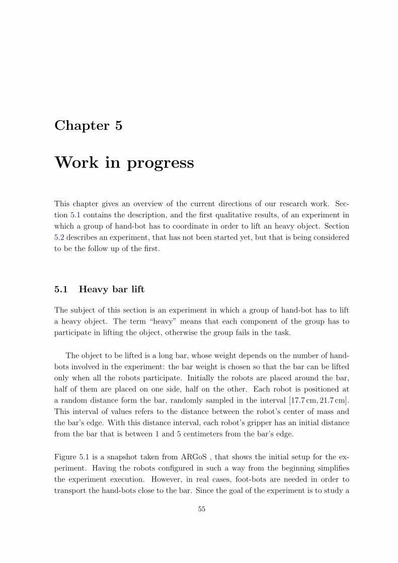
Chapter 5
Work in progress
This chapter gives an overview of the current directions of our research work. Sec-
tion 5.1 contains the description, and the first qualitative results, of an experiment in
which a group of hand-bot has to coordinate in order to lift an heavy object. Section
5.2 describes an experiment, that has not been started yet, but that is being considered
to be the follow up of the first.
5.1 Heavy bar lift
The subject of this section is an experiment in which a group of hand-bot has to lift
a heavy object. The term “heavy” means that each component of the group has to
participate in lifting the object, otherwise the group fails in the task.
The object to be lifted is a long bar, whose weight depends on the number of hand-
bots involved in the experiment: the bar weight is chosen so that the bar can be lifted
only when all the robots participate. Initially the robots are placed around the bar,
half of them are placed on one side, half on the other. Each robot is positioned at
a random distance form the bar, randomly sampled in the interval [17.7 cm, 21.7 cm].
This interval of values refers to the distance between the robot’s center of mass and
the bar’s edge. With this distance interval, each robot’s gripper has an initial distance
from the bar that is between 1 and 5 centimeters from the bar’s edge.
Figure 5.1 is a snapshot taken from ARGoS , that shows the initial setup for the ex-
periment. Having the robots configured in such a way from the beginning simplifies
the experiment execution. However, in real cases, foot-bots are needed in order to
transport the hand-bots close to the bar. Since the goal of the experiment is to study a
55

Figure 5.1: Starting setup for the heavy bar lift experiment. The robots are oriented towardsthe bar, their goal is to grasp and collectively lift it.
Grasp bar
Wait
done
Try Lifting
p Not going up
Going up
Collective Lift
Gone up more
than 25 cm
Figure 5.2: Finite state machine representing the controller for the collective lift of an heavyobject.
strategy that allows to collectively lift an heavy object, we assume that the hand-bots
have already been transported to the right position.
The current implementation of the controller is represented through the finite state
machine depicted in Figure 5.2. The controller acts in three sequential phases:
1. grasp phase
2. coordination phase
3. collective lift phase
The grasp phase corresponds to the state labeled as “Grasp bar” in Figure 5.2. In this
phase the robot stretches its arms, in order to reach the bar. The infrared proximity
56

sensors in the gripper are sampled at each control step, in order to determine when
the bar is close enough to be grasped. A threshold mechanism is used for this purpose:
when all the sensors’ readings are above a certain threshold (95% of the maximum
value), the robot stops stretching its arms and starts to close its gripper.
While the grippers are being closed, the hand-bot monitors the torque readings in
the claws, in order to understand when the bar is safely grasped. When both the torque
sensor readings are above a threshold, the bar is assumed to be grasped and the robot
enters the coordination phase.
During this phase (states “Wait” and “Try lifting” in Figure 5.2) the robot tries to
coordinate with the other hand-bot in order to lift the object. The coordination mech-
anism is very simple: at each control step the hand-bot has a probability p of trying
to lift the bar (at low speed). When the robot is starting to lift (“Try lifting” state
in Fig. 5.2) it monitors the rope length, to check for variations. The rope length does
not change in case the object is too heavy, since the robot cannot manage to go up. If
the rope length does not change for 5 consecutive control steps, the robot gives up and
returns on the ground, where it could eventually start lifting again with probability p.
This procedure is repeated until all the robots eventually synchronize their movements
and start lifting together.
When synchronization occurs, the robot manages to go up, since its efforts sum with
those of the others. Each hand-bot understands that synchronization happened when it
has as climbed 25 cm or more on its rope. When this happens the robot leaves the coor-
dination phase, and enters the collective lift phase (state “Collective lift” in Figure 5.2).
In the collective lift phase the controller sets the rope speed in order to avoid that
the bar inclination goes outside the [−3◦, 3◦] interval. The bar inclination is computed
using the information coming from the gyroscopes and the encoder that measures the
rotation of the arms with respect to the body. Keeping the bar horizontal allows a
distribution of the weight among all the hand-bot and prevents dangerous overloads on
some of the robots.
The strategy has been designed to be as simple as possible. The probabilistic mech-
anism, by which the system manages to coordinate, has been designed to allow for
some energy saving. An alternative solution could be having the robots just keep on
trying lifting the bar, till they are enough to actually lift it. This is not very smart,
since the robots do not know a priori how many individuals are needed to actually
57

lift the object. This means that the robots would be constantly wasting their energies
trying doing something that, potentially, they cannot accomplish. The probabilistic
mechanism introduces some idle time, that allows saving some resources.
Particular attention must be put in tuning the parameters: high lifting probability p
means the robots try to lift the object quite often, wasting their energy in case they are
not enough; low probability p makes it harder to obtain coordination. A possible way
of tackling this issue could be having an adaptive mechanism, in which the probability
is changed dynamically, depending on some environmental cues.
Another possibility is adding communication to explicitly coordinate the system,
but this approach raises some scalability issues. The solution without communication
is probably preferable.
5.2 Heavy board lift
The content of this section is the description of an experiment that is intended to follow
the one described in the previous section. The goal of the experiment is to have a group
of hand-bot lifting an heavy board. As before, “heavy” means that cooperation among
individuals is required in order to accomplish the lifting task.
It might seem that this experiment is pretty much the same as the one described in
the previous section, but lifting a board introduces different dynamics with respect to
lifting a bar. In the case of the bar, relevant torques apply only on one axis, perpen-
dicular to the longitudinal axis of the bar. In order to lift it, the group of robot can
spread along the length of the bar. In a board, torques apply on two axes, thus the
group of hand-bot have to spread around the two dimensions, to balance oscillations
on the two axes.
Figure 5.3 shows the experimental setup, in which a group of hand-bots and a group
of foot-bots are spread around a board to be lifted. In this case, the presence of foot-
bots is explicitly taken into account, their role is to reposition the hand-bots around
the board, when needed. Concerning the hand-bot, the controller has to extend the one
described in the previous section, since coordination among the robots must be found
in order to lift the board. In addition, the group must be able to understand when is
the case of repositioning some of its members around the board, and communicate this
decision to the foot-bots.
58
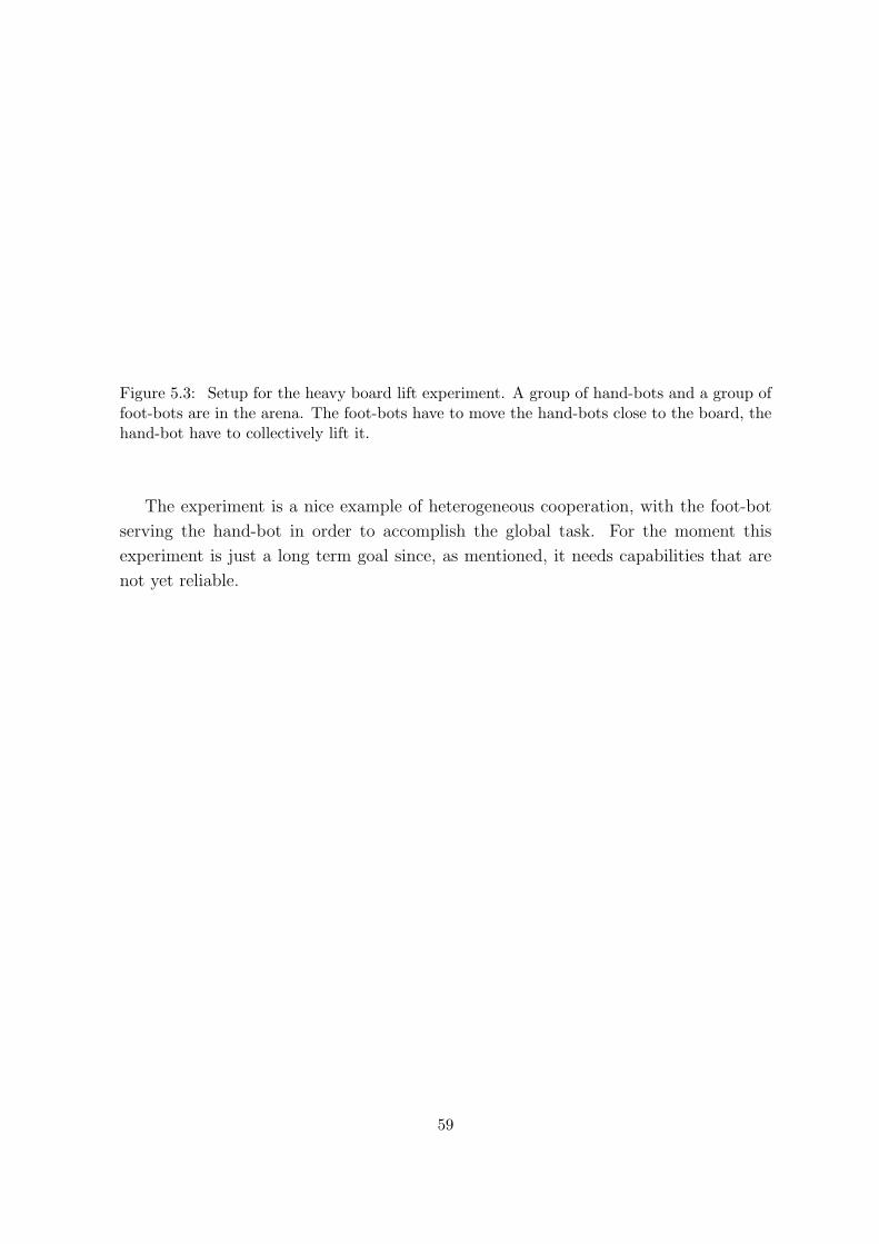
Figure 5.3: Setup for the heavy board lift experiment. A group of hand-bots and a group offoot-bots are in the arena. The foot-bots have to move the hand-bots close to the board, thehand-bot have to collectively lift it.
The experiment is a nice example of heterogeneous cooperation, with the foot-bot
serving the hand-bot in order to accomplish the global task. For the moment this
experiment is just a long term goal since, as mentioned, it needs capabilities that are
not yet reliable.
59

60

Chapter 6
Conclusions and future work
Cooperation among individuals in a swarm of robots can lead the group to perform
tasks in a three dimensional space that none of its components could do alone. The
work presented in this report, summarizing the ongoing research, suggests that swarm-
robotics approach can be extended to tasks that develop in three dimensions.
We have described a new robotic concept, called a Swarmanoid, made of an innova-
tive distributed robotic system comprising heterogeneous, dynamically connected, small
autonomous robots. We explained in details the characteristics of each of the robots,
with particular attention to the hand-bot. We introduced the simulation framework of
the Swarmanoid project, focusing on the 3D dynamics physics engine and on the hand-
bot model. We presented the first simulation results, that concern the development of
controllers for the hand-bot:
1. A controller that allows a single robot to grasp objects;
2. A controller that allows two robots to cooperatively lift a bar;
3. A controller that allows two robots to explore a vertical plane;
The contributions of the work presented are:
• The development of a fully functional ODE model of the hand-bot robot, including
all the sensors and actuators. The model is available for all the members of the
Swarmanoid project, and can be used for their research;
• The development of the first controllers for the hand-bot;
The first simulation results confirm that cooperation is beneficial also in tasks that
develop in the third dimension. The experiments presented in Chapter 4 show that
the benefits coming from cooperation enhance the capability of the system, allowing to
perform tasks that go far beyond the capabilities of a single hand-bot.
61
Future Work
The current model of the hand-bot is fully functional and reflects the main characteris-
tic of what will be the real robot. Nevertheless, the parameters of the model need to be
tuned properly, to match the hardware. The exact size and weight of the robot parts
is not known with precision at the moment and should be measured once the robot is
available.
The same applies for the sensors and the actuators. Important parameters are still
not known: the speed of the limbs, the climbing speed, the success rate of the rope
launcher, the maximum torques that can be applied by the motors. During the devel-
opment of the model, those parameters have shown to characterise the behavior of the
robot, thus they impact on the controllers.
Concerning the sensors, noise models need to be determined and then parametrised.
The cameras model needs to be improved: as mentioned in section 2.3, the actual im-
plementation is very simple since it is not known which image characteristic can be
extracted using the hardware. The controllers described in this work do not make use
of the cameras, but this sensor will be very useful for locating objects and will allow
experiments involving vision.
Another direction of the research is to implement the controllers described in this
report on the real robots. The simulator is built to allow transferring the controllers
directly to the hardware without any modifications, but it is a known issue that mov-
ing from simulation to reality is far from being straightforward. The controllers need
tuning to behave in a proper way on the robots.
More experiments highlighting the swarm-robotics aspects will be designed and im-
plemented using the same approach of simulations followed by real robot validation.
We believe this research work will constitute a small but remarkable step towards the
application of swarm-robotics in a class of tasks, those developing in three dimensions,
that has been marginally tackled in the literature.
62

Bibliography
Ahmadabadi, M. N. & Eiji, N. (2001), ‘A ”costrain and move” approach to distributed
object manipulation’, IEEE Transactions on Robotics and Automation 17, 157–171.
Bayindir, L. & Sahin, E. (2007), ‘A review of studies in swarm robotics’, Turkish Journal
of Electrical Engineering and Computer Sciences 15(2).
Ben-Jacob, E., Cohen, I. & Levine, H. (2000), ‘Cooperative self-organization of mi-
croorganisms’, Advance in physics 49(4), 395–554.
Beni, G. (2004), From swarm intelligence to swarm robotics, in ‘Proceedings of Work-
shop on Swarm Robotics, 8th Internationall Conference on Simulation of Adaptive
Behavior’, Los Angeles, USA.
Bonabeau, E., Dorigo, M. & Theraulaz, G. (1999), Swarm Intelligence: From Natural
to Artificial Systems, Santa Fe Institute Studies in the Science of Complexity, Oxford
University Press, New York, NY, USA.
Bonabeau, E., Dorigo, M. & Theraulaz, G. (2000), ‘Inspiration for optimization from
social insect behaviour’, Nature 406(6791), 39–42.
Camazine, S., Deneubourg, J.-L., Franks, N. R., Sneyd, J., Theraulaz, G. & Bonabeau,
E. (2003), Self-Organization in Biological Systems, Princeton Studies in Complexity,
Princeton University Press, Princeton, NJ, USA.
Cao, Y. U., Fukunaga, A. S. & Kahng, A. B. (1997), ‘Cooperative mobile robotics:
Antecedents and directions’, Autonomous Robots 4, 226–234.
Christensen, A., O’Grady, R. & Dorigo, M. (2007), Morphogenesis: Shaping swarms of
intelligent robots, in ‘AAAI-07 Video Proceedings’, AAAI Press.
Detrain, C. & Deneubourg, J. L. (2006), Physics of Life Reviews 3(3), 162–187.
Dorigo, M. & Stutzle, T. (2004), Ant Colony Optimization, MIT Press, Cambridge,
MA.
63
Dorigo, M., Tuci, E., Mondada, F., Nolfi, S., Deneubourg, J. L., Floreano, D. & Gam-
bardella, L. M. (2005), ‘The SWARM-BOTS project’, Knstliche Intelligenz 4/05, 32–
35.
Garnier, S., Gautrais, J. & Theraulaz, G. (2007), ‘The biological principles of swarm
intelligence’, Swarm Intelligence 1(1), 3–31.
Gautrais, J., Michelena, P., Sibbald, A., Bon, R. & Deneubourg, J. L. (2007), ‘Al-
lelomimetic synchronisation in merino sheep’, Animal Behaviour 74, 1443–1454.
Grunbaum, D., Viscido, S. & Parrish, J. K. (2004), ‘Extracting interactive control
algorithms from group of schooling fish’, Lecture Notes in Control and Information
Sciences 309, 103–117.
J. Fink, M.A. Hsieh, V. K. (2008), ‘Multi-robot manipulation via caging in environ-
ments with obstacles’, IEEE International Conference on Robotics and Automation
pp. 1471 – 1476.
Jacobi, N. (1997), Half-baked, ad-hoc and noisy: Minimal simulations for evolutionary
robotics, in P. Husbands & I. Harvey, eds, ‘Proceedings of the Fourth European
Conference on Artificial Life: ECAL97’, MIT Press, Cambridge, MA, USA, pp. 348–
357.
Kube, R. & Zhang, H. (1993), ‘Collective robotics: From social insects to robots’,
Adaptive Behavior 2, 189–218.
Mondada, F., Bonani, M., Guignard, A., Magnenat, S., Studer, C. & Floreano, D.
(2005), Superlinear physical performances in a swarm-bot, in ‘In Advances in Artifi-
cial Life: 8th European Conf., ECAL 2005’, Springer-Verlag, pp. 282–291.
Mondada, F., Pettinaro, G. C., Guignard, A., Kwee, I. W., Floreano, D., Deneubourg,
J.-L., Nolfi, S., Gambardella, L. M. & Dorigo, M. (2004), ‘Swarm-bot: A new dis-
tributed robotic concept’, Autonomous Robots 17(2–3), 193–221.
Murphy, M. P., Aksak, B. & Sitti, M. (2009), ‘Gecko-inspired directional and control-
lable adhesion’, Small 5(2), 170–175.
Nouyan, S., Campo, A. & Dorigo, M. (2008), ‘Path formation in a robot swarm: Self-
organized strategies to find your way home’, Swarm Intelligence 2(1), 1–23.
Reynolds, C. W. (1987), ‘Flocks, herds, and schools: A distributed behavioral model’,
Computer Graphics 21(4), 25–34.
64

Seugling, A. & Rolin, M. (2006), Evaluation of physics engines and implementation of
a physics module in a 3d-authoring tool, Master’s thesis, Department of Computer
Science, Umeoa University, Sweden.
Smith, R. (2001), ‘Open dynamics engine’, http://ode.org.
Sugar, T. G. & Kumar, R. V. (2002), ‘Control of cooperating mobile manipulators’,
IEEE Transactions on Robotics and Automation 18(1), 94 – 103.
65


![(Version préliminaire) Vincent Gautrais et Pierre Trudel · [gautrais et trudel, 2010]. 1A2 Limites à la protection des renseignements personnels Les droits fondamentaux sont protégés](https://static.fdocuments.net/doc/165x107/5b98bb5709d3f2085f8c2677/version-preliminaire-vincent-gautrais-et-pierre-gautrais-et-trudel-2010.jpg)