Toward an Eastern Mediterranean Integrated Gas Infrastructure?
Toward Integrated Motion Planning and Controlusing Potential Fields and Torque-based Steering Actuation
for Autonomous Driving
Enric Galceran, Ryan M. Eustice, and Edwin Olson
Abstract— This paper proposes an integrated motion plan-ning and control approach for autonomous car navigation.Existing approaches to autonomous vehicle navigation typicallyplan a trajectory and pass it on to a steering controller thatcommands steering wheel angle (SWA) or curvature at everytimestep to minimize tracking error. However, this approachexhibits large amounts of control effort, and ignores othercriteria such as smoothness or the importance of staying onplan at different times. Conversely, our proposed approachleverages the concept of potential fields to represent a drivingcorridor with a desired tracking error tolerance and directtorque-based steering control to smoothly steer the vehiclewith a much smaller control effort. Further, using potentialfields allows us to naturally incorporate obstacles in thedriving corridor to circumvent them, with typically no needfor explicit trajectory planning. We compare our approach toa standard steering controller in experiments with a real-worldautonomous vehicle platform. Results show that our proposedapproach achieves similar path tracking performance as a high-gain SWA controller, but with much less actuator effort.
I. INTRODUCTIONMost control systems in autonomous cars steer the vehicle
using steering wheel angle (SWA) commands or, similarly,curvature commands (see, e.g., [1], [2], [3]). This approachhas been shown to be moderately successful, especiallythroughout the DARPA Grand and Urban Challenges [4].
Nonetheless, using a position command (i.e. SWA orcurvature) to steer the vehicle can be sub-optimal in somesituations. Consider for instance a vehicle making a 90-degree turn at an intersection. Throughout the turning ma-neuver, external forces will act on the steering column,most conspicuously self-aligning torque, which tends to alignthe tires along the vehicle’s direction of travel. A position-based controller will “fight” those forces during the entiremaneuver, exerting a large amount of control effort to keepthe steering wheel at a sequence of exact angles to trackthe cornering path. This vividly contrasts with how a humandriver would intuitively exploit the restoring forces once thevehicle is heading toward the end of the turn, that is, relaxingthe torque applied to the steering wheel and allowing therestoring forces to align the vehicle along the path ratherthan forcing the steering wheel at particular angles.
Similarly, when driving along a lane with only mild curvesat close to constant speed (which encompasses a great part of
This work was supported in part by a grant from Ford Motor Companyvia the Ford-UM Alliance under award N015392 and in part by DARPAunder award D13AP00059.
The authors are with the University of Michigan, Ann Arbor, MI 48109,USA. {egalcera,eustice,ebolson}@umich.edu
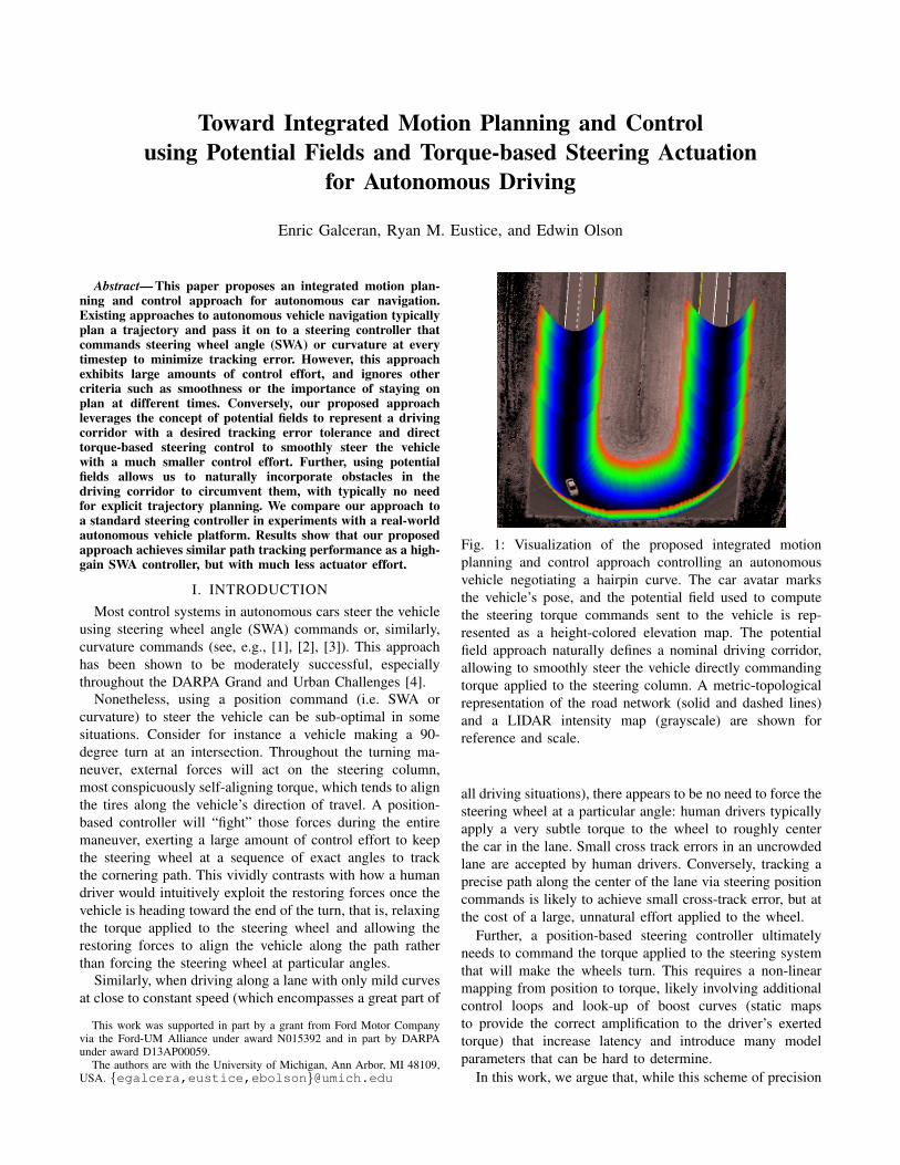
Fig. 1: Visualization of the proposed integrated motionplanning and control approach controlling an autonomousvehicle negotiating a hairpin curve. The car avatar marksthe vehicle’s pose, and the potential field used to computethe steering torque commands sent to the vehicle is rep-resented as a height-colored elevation map. The potentialfield approach naturally defines a nominal driving corridor,allowing to smoothly steer the vehicle directly commandingtorque applied to the steering column. A metric-topologicalrepresentation of the road network (solid and dashed lines)and a LIDAR intensity map (grayscale) are shown forreference and scale.
all driving situations), there appears to be no need to force thesteering wheel at a particular angle: human drivers typicallyapply a very subtle torque to the wheel to roughly centerthe car in the lane. Small cross track errors in an uncrowdedlane are accepted by human drivers. Conversely, tracking aprecise path along the center of the lane via steering positioncommands is likely to achieve small cross-track error, but atthe cost of a large, unnatural effort applied to the wheel.
Further, a position-based steering controller ultimatelyneeds to command the torque applied to the steering systemthat will make the wheels turn. This requires a non-linearmapping from position to torque, likely involving additionalcontrol loops and look-up of boost curves (static mapsto provide the correct amplification to the driver’s exertedtorque) that increase latency and introduce many modelparameters that can be hard to determine.
In this work, we argue that, while this scheme of precision
steering might be useful for tracking “threading-the-needle”paths, as may be required in parking maneuvers or sharpturns, there are many situations in which steering the vehicleusing a direct torque input has the potential to yield morenatural driving behavior and lower control effort.
To this aim, we present an integrated motion planningand control approach that leverages a torque-based steeringinterface in conjunction with potential fields [5] to commandan autonomous vehicle. Using potential fields allows todefine a driving corridor with some acceptable tolerance(e.g., driving along a lane), as opposed to following anarbitrarily stringent trajectory (e.g., tracking the center ofa lane). In this way, planning and control are unified, sincethe controller is aware of how serious tracking errors are(or are not), being able to adapt its response accordingly. Incontrast, traditional approaches typically employ a fixed andhigh gain regardless. Furthermore, potential fields providea connection between planning and control by being ableto readily incorporate obstacles in the environment, yieldingsteering commands that can smoothly circumvent them. Thevisualization in Fig. 1 illustrates the proposed approach.
Our approach seeks to1) leverage a direct steering torque input to more naturally
exploit external forces on the vehicle to counter steer,2) use a potential field to reflect the importance of remaining
on a specific path at each point in space and time and toeasily account for obstacles,
3) require less dependence on precise models of the system(e.g., mappings from SWA to steering torque), which arecomplex given the external forces on the car and subjectto change from vehicle to vehicle.
We show the feasibility of the proposed approach in aseries of runs with an autonomous vehicle on a closed testtrack, demonstrating free-form steering maneuvers, followingof tightly curved roads and obstacle avoidance capabilities.Further, we compare our approach to a SWA-based steeringcontroller in terms of path tracking error and control effort.Our results show that our approach achieves a similar levelof path-tracking error at a significantly lower control effort.
We note that, in this work, we focus on steering or lateralcontrol of the vehicle, whereas longitudinal or speed controlis assumed to be handled by an appropriate control module,as is the case for the autonomous vehicle platform we usein our experiments.
II. RELATED WORK
Most autonomous car platforms developed up to dateapproach the navigation problem (that is, safely driving thevehicle to a desired goal) by first planning a specific pathto a goal and then tracking it using a feedback controller.Such nominal path is typically obtained using search-basedplanning algorithms [6], sampling-based planning [7] ornumerical optimization [8]. Once a path is available, it istypically tracked by the controller using SWA or curvaturecommands with the primary objective of minimizing trackingerror (see, e.g., [1], [2], [3]), leading to the aforementioned
disadvantages. Further, large amounts of computational re-sources are spent on finding a collision-free path in theplanning phase.
The concept of a driving corridor is common in mobilerobotics, although they are often conceived to representobstacle-free regions of the environment, such as in the workof Geraerts and Overmars [9] and Wein et al. [10]. Moresimilarly to our approach, Dolgov et al. [11] develop a local-minima-free cost-map based on a Voronoi decomposition ofthe robot’s static obstacle map. However, the driving corridorwe propose in this work is defined in terms of a potential fielddesigned to provide an easily differentiable potential functionthat is convex with respect to the lateral offset of the vehiclefrom the center of the nominal path, and is directly relatedto the torque input applied to steer the vehicle.
Potential fields for robotic navigation are certainly notnew, originating almost three decades ago (see [5] for atutorial). Wolf et al. proposed artificial potential functionsfor highway driving [12], but their results are limited tosimulations. However, in this work we adopt the conceptin combination with a torque-based steering controller forsmooth steering of an autonomous vehicle, circumventing thelimitations of potential fields when applied to non-holonomicsystems and arbitrarily complex obstacle maps [13]. Otherresearchers have proposed controlling steering torque di-rectly [14], [15], although these approaches focus on trajec-tory tracking rather than exploiting perceptual informationof the vehicle’s surroundings such as the presence of othertraffic participants or the deviation from the lane center.
III. METHODOur proposed integrated motion planning and control
method consists of two main components: a driving corridorconstructed using a potential field and a steering controllerthat exploits a torque-based steering interface. The potentialfield is composed of a steering component that guides thevehicle toward its nominal path and obstacle potentialsdriven by the presence of static obstacles and other vehiclesparticipating in traffic.
A. Potential Field
We construct a potential field to represent the vehicle’sdriving corridor by means of a potential energy function U :R2 → R:
U(x) = Uatt + Urep, (1)
where x is a point on the vehicle’s 2-dimensional plane, Uatt
is the attractive potential that guides the vehicle toward thenominal path and Urep is the repulsive potential that vectorsthe vehicle away from obstacles in the environment. Theobjective of the vehicle is to minimize the energy of thispotential by commanding a steering torque input based onthe negative gradient of the potential energy function:
−∇U(x) = −DU(x) = −[∂U
∂x1(x),
∂U
∂x2(x)
]>. (2)
We generate the attractive potential Uatt around a nominalpath of travel (e.g., the lane center), which can be obtained,
for instance, from a prior road network map or using a mo-tion planner (see, e.g., [16], [17]). Given a nominal path Π asa sequence of N 2-dimensional waypoints Π = w1, . . . , wN ,we consider attractive potentials Uatt(x) for all points x ina local neighborhood of the vehicle of the form
Uatt(x) = di(x,Π), i ∈ N, i > 0, (3)
where d(x,Π) is the distance from a point x to its closestsegment in the path Π. We have empirically found a quadraticpotential, i.e., i = 2 to provide sufficient control authorityto steer the vehicle on the nominal path, whereas a linearpotential (i = 1) required a high proportional gain onthe feedback controller (see Section III-B below) leadingto instability, and higher orders (i > 2) did not providesubstantially different performance compared to a quadraticpotential. Thus, we define our potential as
Uatt(x) = d2(x,Π). (4)
The quadratic cost function in Eq. 4 avoids local minimaby having a zero cost centerline, is convex with respect tothe robot’s lateral offset in its nominal path, and allowsfor straightforward calculation of derivatives even withinobstacle regions.
Fig. 1 shows an example of an attractive potential fieldgenerated at a hairpin curve section of a test track, followingthe center of a desired lane of travel.
Similarly, we use a quadratic potential Urep in the vicinityof obstacles (we discuss a test run of our system involvinga repulsive potential below in Section V-C). By addingthe attractive and repulsive potentials, we obtain the totalpotential U(x) = Uatt + Urep whose potential function, perEq. 2, is given by
F (x) = − ||∇U(x)|| . (5)
While local minima in potential fields are a problemfor systems that use them to make progress toward a goallocation [13], here the potential field is specifically con-structed to control the vehicle’s steering actuator (leavingout longitudinal control), and therefore any minimum thereinrepresents an acceptable corridor for the vehicle to drivethrough. The degenerate case where the driving corridor iscompletely blocked by obstacles is easily handled by thelongitudinal control module, commanding the vehicle to stopupon that circumstance.
A shortcoming of most potential field methods is thatthey complicate analysis of the closed-loop control system.However, since our potential U(x) is a quadratic function,its gradient is given as
∇U(x) =
[∂U
∂x1(x),
∂U
∂x2(x)
]>= [C1x1, C2x2]
> , (6)
where C1 and C2 are constants. Therefore, F (x) is equiva-lent to a proportional gain obtained from the potential field.However, a proportional gain does not suffice to stabilizethe system at hand, which if approximated by the simplifiedsystem Ψ̈ = τ (where Ψ̈ is the yaw acceleration of the
vehicle and τ is the applied torque) is at least second-order.This theoretical limitation is further supported by initial testswith our autonomous vehicle system. Thus, we put forwardthe following feedback steering controller.
B. Torque-based Steering Controller
Given the potential field introduced above, we use aproportional-derivative (PD) feedback controller to issue atorque command to the steering system as a function of thepotential field. The control objective is to steer the vehiclefollowing the potential function in Eq. 5, as shown in Fig. 1.
More precisely, the input variable to the controller is thepotential function F (xt+L), evaluated at a point xt+L locatedat some lookahead time L seconds in the future, where xtis the position of the center of the rear axle of the vehicle attime t. Thus, the torque command at time t is given as
τ(t) = KpF (xt+L) +Kdd
dtF (xt+L), (7)
where Kp is the proportional gain and Kd is the derivativegain (tuning parameters). The block diagram of the feedbackcontroller is shown in Fig. 2.
PD CONTROLLER VEHICLE PLANT
Torque
output
Vehicle
pose
POTENTIAL FIELD
Potential
Gradient
Fig. 2: PD feedback control loop for torque-based steering.
IV. EXPERIMENTAL SETUPA. Test Surfaces
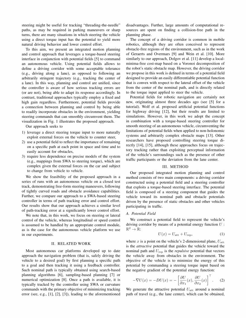
We have evaluated our proposed approach using ourautonomous vehicle platform on several runs on differentsurfaces of a test track located at the Dearborn DevelopmentCenter (DDC) facilities of the Ford Motor Co., using thevehicle dynamics area (VDA), steering and handling course(SHC) and low speed straightaway (LSSA) test surfaces(Fig. 3). The VDA test surface provides an ample pavedspace to perform free-form steering runs, the SHC consistsof a narrow two-lane road with sharp curves and pronouncedslope changes, and the LSSA consists in a two-lane loop withtwo long straightaways.
Fig. 3: Test surfaces at Ford’s DDC used in our experiments.Image credit: Google, Digital Globe, Sanborn, U.S. Geolog-ical Survey, USDA Farm Service Agency.
B. Experimental Platform
The experimental platform we use in our experimentsconsists of a Ford Fusion vehicle, equipped with a drive-by-wire system featuring a steering interface that can beconfigured to accept either SWA or torque requests.
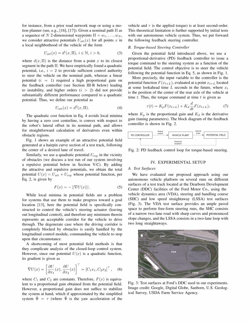
The vehicle, shown in Fig. 4, is equipped with four Velo-dyne HDL-32E 3D LIDAR scanners, an Applanix POS-LV420 inertial navigation system (INS), GPS, and several othersensors. An onboard five-node computer cluster performs allplanning, control, and perception for the system in realtime.In particular, our implementation of the proposed approachruns onboard the vehicle at 20 Hz.
Fig. 4: Our autonomous car platform, a Ford Fusion equippedwith four LIDAR units, survey-grade INS, and a steeringinterface able to operate in both SWA and steering torquemode. All perception and control is performed onboard.
The vehicle uses prior maps of the area it operateson, which capture information about the environment suchas LIDAR reflectivity and road height, and are used forlocalization, obstacle detection, and other perceptual tasks.The road network is encoded as a metric-topological mapusing a derivative of the route network definition file (RNDF)format [4], providing information about the location and con-nectivity of road segments and lanes therein. Desired pathsof travel can be obtained leveraging this prior knowledge.
Estimates over the states of other traffic participants areprovided by a dynamic object tracker running on the vehicle,which uses LIDAR range measurements. The geometry andlocation of static obstacles are also inferred on board usingLIDAR measurements.
V. RESULTS
We now present preliminary results obtained after eval-uating the proposed approach on our autonomous vehicleplatform. We initially run straight line maneuvers and free-form steering maneuvers with increasing curvature on theVDA surface, moving at low forward speeds (∼4 m/s). Wethen evaluated the performance of the system on severalruns on the SHC, moving at speeds up to 7 m/s. Finallywe performed several runs with maneuvers involving thepresence of obstacles (i.e., involving potential fields withobstacle components) again on the VDA at lower speeds.We use a lookahead time L =1.5 s in all experiments.
A. Initial Tests
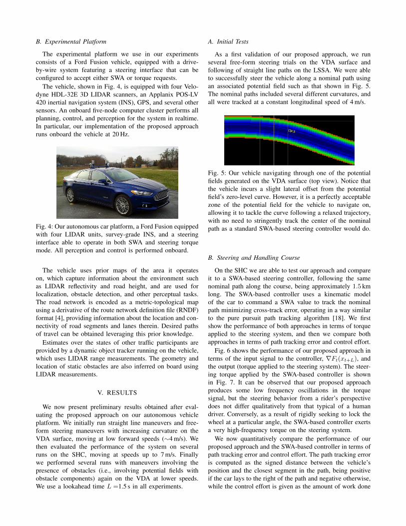
As a first validation of our proposed approach, we runseveral free-form steering trials on the VDA surface andfollowing of straight line paths on the LSSA. We were ableto successfully steer the vehicle along a nominal path usingan associated potential field such as that shown in Fig. 5.The nominal paths included several different curvatures, andall were tracked at a constant longitudinal speed of 4 m/s.
Fig. 5: Our vehicle navigating through one of the potentialfields generated on the VDA surface (top view). Notice thatthe vehicle incurs a slight lateral offset from the potentialfield’s zero-level curve. However, it is a perfectly acceptablezone of the potential field for the vehicle to navigate on,allowing it to tackle the curve following a relaxed trajectory,with no need to stringently track the center of the nominalpath as a standard SWA-based steering controller would do.
B. Steering and Handling Course
On the SHC we are able to test our approach and compareit to a SWA-based steering controller, following the samenominal path along the course, being approximately 1.5 kmlong. The SWA-based controller uses a kinematic modelof the car to command a SWA value to track the nominalpath minimizing cross-track error, operating in a way similarto the pure pursuit path tracking algorithm [18]. We firstshow the performance of both approaches in terms of torqueapplied to the steering system, and then we compare bothapproaches in terms of path tracking error and control effort.
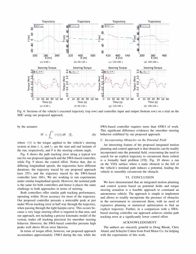
Fig. 6 shows the performance of our proposed approach interms of the input signal to the controller, ∇Ft(xt+L), andthe output (torque applied to the steering system). The steer-ing torque applied by the SWA-based controller is shownin Fig. 7. It can be observed that our proposed approachproduces some low frequency oscillations in the torquesignal, but the steering behavior from a rider’s perspectivedoes not differ qualitatively from that typical of a humandriver. Conversely, as a result of rigidly seeking to lock thewheel at a particular angle, the SWA-based controller exertsa very high-frequency torque on the steering system.
We now quantitatively compare the performance of ourproposed approach and the SWA-based controller in terms ofpath tracking error and control effort. The path tracking erroris computed as the signed distance between the vehicle’sposition and the closest segment in the path, being positiveif the car lays to the right of the path and negative otherwise,while the control effort is given as the amount of work done
(a) 0-60 s (b) 60-120 s (c) 120-180 s (d) 180-240 s
(e) 0-60 s (f) 60-120 s (g) 120-180 s (h) 180-240 s
Fig. 6: Sections of the vehicle’s executed trajectory (top row) and controller input and output (bottom row) on a trial on theSHC using our proposed approach.
by the actuator:
W =
∫ tf
t0
|τ(t)| dθ [J], (8)
where τ(t) is the torque applied to the vehicle’s steeringsystem at time t, t0 and tf are the start and end instants ofthe run, respectively, and θ is the steering column angle.
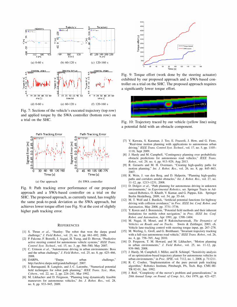
Fig. 8 shows the path tracking error along a typical testrun for our proposed approach and the SWA-based controller,while Fig. 9 shows the control effort. Notice that, due todiffering longitudinal speeds, the trajectories have differentdurations: the trajectory traced by our proposed approachlasts 255 s and the trajectory traced by the SWA-basedcontroller lasts 160 s. We are working to run experimentsunder similar longitudinal speeds. However, the nominal pathis the same for both controllers and hence it places the samechallenge to both approaches in terms of steering.
Both controllers offer similar path tracking performance,operating within 30 cm accuracy for most of the trajectory.Our proposed controller presents a noticeable peak at justunder 90 cm tracking error at half way through the trajectory,when passing through the tight hairpin curve. This occurs be-cause a very large steering effort is required in that area, andour approach, not including a precise kinematic model of thesystem, trades off tracking precision for smoother steeringbehavior. However, the SWA-based controller presents highpeaks well above 60 cm error likewise.
In terms of torque effort, however, our proposed approachaccumulates approximately 1500 J during the run, while the
SWA-based controller requires more than 4500 J of work.This significant difference evidences the smoother steeringbehavior exhibited by our proposed approach.
C. Incorporating Obstacles on the Potential Field
An interesting feature of the proposed integrated motionplanning and control approach is that obstacles can be readilyincorporated onto the potential field, overcoming the need tosearch for an explicit trajectory to circumvent them (whichis a formally hard problem [19]). Fig. 10 shows a runon the VDA surface where a static obstacle to the left ofthe vehicle’s nominal path induces a potential, leading thevehicle to smoothly circumvent the obstacle.
VI. CONCLUSIONWe have demonstrated that an integrated motion planning
and control system based on potential fields and torquesteering actuation is a feasible approach to command anautonomous vehicle. The approach is simple to implementand allows to readily incorporate the presence of obstaclesin the environment to circumvent them, with no need ofexpensive planning or numerical optimization to find anexplicit trajectory. Further, in a comparison with a SWA-based steering controller our approach achieves similar pathtracking error at a significantly lower control effort.
ACKNOWLEDGMENTThe authors are sincerely grateful to Doug Rhode, Chris
Attard, and Schuyler Cohen from Ford Motor Co. for helpingwith the experiments of this work.
(a) 0-60 s (b) 60-120 s (c) 120-160 s
(d) 0-60 s (e) 60-120 s (f) 120-160 s
Fig. 7: Sections of the vehicle’s executed trajectory (top row)and applied torque by the SWA controller (bottom row) ona trial on the SHC.
(a) Our approach (b) SWA controller
Fig. 8: Path tracking error performance of our proposedapproach and a SWA-based controller on a trial on theSHC. The proposed approach, as currently tuned, has roughlythe same peak-to-peak deviation as the SWA approach, butachieves lower torque effort (see Fig. 9) at the cost of slightlyhigher path tracking error.
REFERENCES
[1] S. Thrun et al., “Stanley: The robot that won the darpa grandchallenge,” J. Field Robot., vol. 23, no. 9, pp. 661–692, 2006.
[2] P. Falcone, F. Borrelli, J. Asgari, H. Tseng, and D. Hrovat, “Predictiveactive steering control for autonomous vehicle systems,” IEEE Trans.Control Syst. Technol., vol. 15, no. 3, pp. 566–580, May 2007.
[3] C. Urmson et al., “Autonomous driving in urban environments: Bossand the urban challenge,” J. Field Robot., vol. 25, no. 8, pp. 425–466,2008.
[4] DARPA, “Darpa urban challenge,”http://archive.darpa.mil/grandchallenge/, 2007.
[5] J. Barraquand, B. Langlois, and J.-C. Latombe, “Numerical potentialfield techniques for robot path planning,” IEEE Trans. Syst., Man,Cybern., vol. 22, no. 2, pp. 224–241, Mar 1992.
[6] M. Likhachev and D. Ferguson, “Planning long dynamically feasiblemaneuvers for autonomous vehicles,” Int. J. Robot. Res., vol. 28,no. 8, pp. 933–945, 2009.
Fig. 9: Torque effort (work done by the steering actuator)exhibited by our proposed approach and a SWA-based con-troller on a trial on the SHC. The proposed approach requiresa significantly lower torque effort.
Fig. 10: Trajectory traced by our vehicle (yellow line) usinga potential field with an obstacle component.
[7] Y. Kuwata, S. Karaman, J. Teo, E. Frazzoli, J. How, and G. Fiore,“Real-time motion planning with applications to autonomous urbandriving,” IEEE Trans. Control Syst. Technol., vol. 17, no. 5, pp. 1105–1118, Sept 2009.
[8] J. Hardy and M. Campbell, “Contingency planning over probabilisticobstacle predictions for autonomous road vehicles,” IEEE Trans.Robot., vol. 29, no. 4, pp. 913–929, Aug 2013.
[9] R. Geraerts and M. H. Overmars, “Creating high-quality paths formotion planning,” Int. J. Robot. Res., vol. 26, no. 8, pp. 845–863,2007.
[10] R. Wein, J. van den Berg, and D. Halperin, “Planning high-qualitypaths and corridors amidst obstacles,” Int. J. Robot. Res., vol. 27, no.11-12, pp. 1213–1231, 2008.
[11] D. Dolgov et al., “Path planning for autonomous driving in unknownenvironments,” in Experimental Robotics, ser. Springer Tracts in Ad-vanced Robotics, O. Khatib, V. Kumar, and G. Pappas, Eds. SpringerBerlin Heidelberg, 2009, vol. 54, pp. 55–64.
[12] M. T. Wolf and J. Burdick, “Artificial potential functions for highwaydriving with collision avoidance,” in Proc. IEEE Int. Conf. Robot. andAutomation, May 2008, pp. 3731–3736.
[13] Y. Koren and J. Borenstein, “Potential field methods and their inherentlimitations for mobile robot navigation,” in Proc. IEEE Int. Conf.Robot. and Automation, Apr 1991, pp. 1398–1404.
[14] M. Nagai, H. Mouri, and P. Raksincharoensak, The Dynamics ofVehicles on Roads and on Tracks. Swets & Zeitlinger, 2003, ch.Vehicle lane-tracking control with steering torque input, pp. 267–278.
[15] M. Werling, L. Groll, and G. Bretthauer, “Invariant trajectory trackingwith a full-size autonomous road vehicle,” IEEE Trans. Robot., vol. 26,no. 4, pp. 758–765, Aug 2010.
[16] D. Ferguson, T. M. Howard, and M. Likhachev, “Motion planningin urban environments,” J. Field Robot., vol. 25, no. 11-12, pp.939–960, 2008.
[17] J. Hardy, M. Campbell, I. Miller, and B. Schimpf, “Sensitivity analysisof an optimization-based trajectory planner for autonomous vehicles inurban environments,” in Proc. SPIE, vol. 7112, no. 1, 2008, p. 711211.
[18] R. C. Coulter, “Implementation of the pure pursuit path trackingalgorithm,” Robotics Institute, Pittsburgh, PA, Tech. Rep. CMU-RI-TR-92-01, Jan. 1992.
[19] J. Reif, “Complexity of the mover’s problem and generalizations,” in20th Annual Symp. on Found. of Comp. Sci., Oct 1979, pp. 421–427.