Toward dependable interactive systems: dealing with system ... · Toward dependable interactive...
69
Toward dependable interactive systems: dealing with system faults at development and run time Camille Fayollas Interactive Critical Systems research group (IRIT) & Dependable Computing and Fault Tolerance research group (LAAS-CNRS) http://www.irit.fr/~Camille.Fayollas - [email protected] January 6 th 2016
Transcript of Toward dependable interactive systems: dealing with system ... · Toward dependable interactive...
1
Toward dependable interactive systems:dealing with system faults
at development and run time
Camille Fayollas
Interactive Critical Systems research group (IRIT)
& Dependable Computing and Fault Tolerance research group (LAAS-CNRS)
http://www.irit.fr/~Camille.Fayollas - [email protected]
January 6th 2016
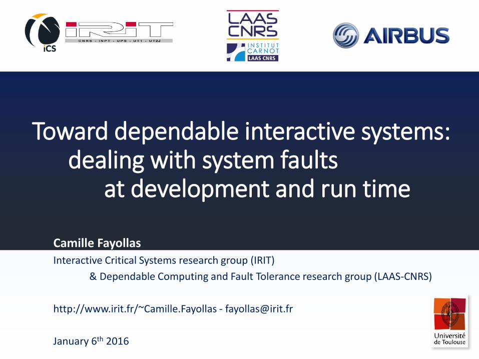
2HCI in Critical Context
User Centered Design (ISO 9241-210)
Usability (ISO 9241-11)
EffectivenessEfficiencySatisfaction
Dependable Approach(prevention, tolerance, removal, forecasting)
Standards (ARP 4754), Development processes (DO-178C), Certification
Interactive Systems Critical Systems
3
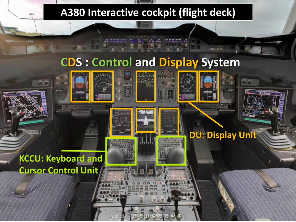
DU: Display Unit
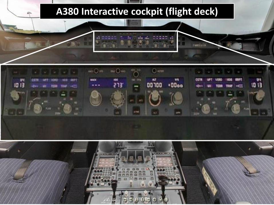
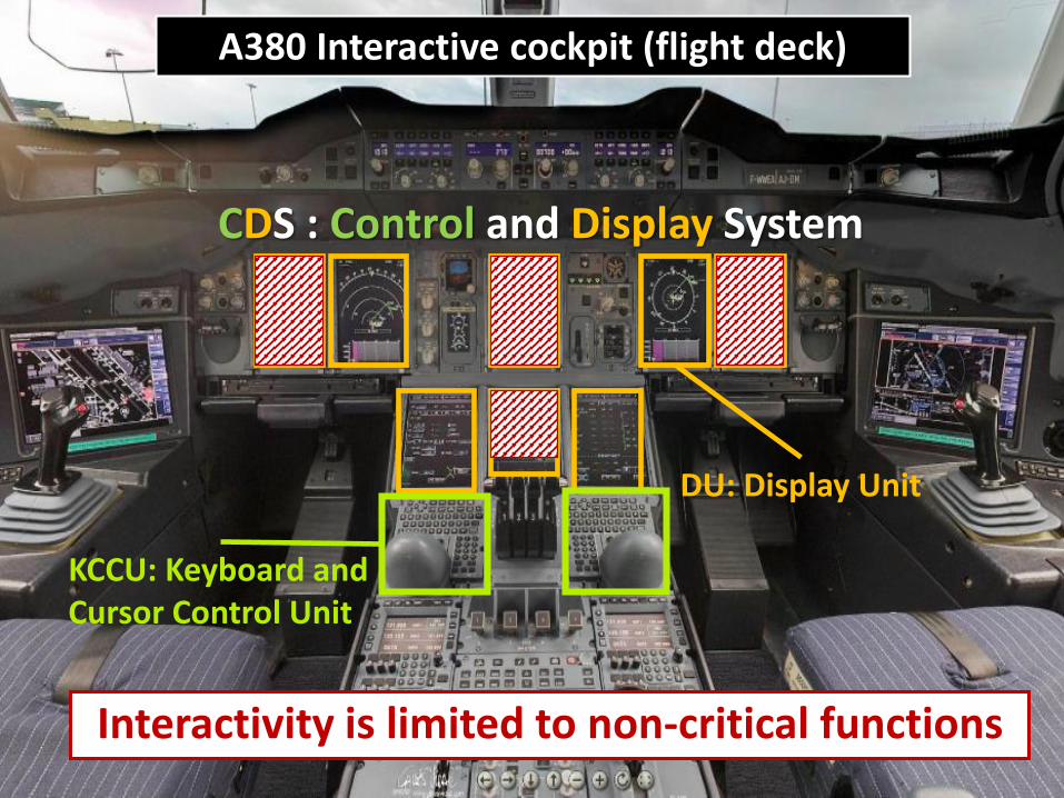
A380 Interactive cockpit (flight deck)
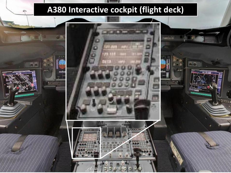
4A380 Interactive cockpit (flight deck)
5
DU: Display Unit
KCCU: Keyboard and Cursor Control Unit
CDS : Control and Display System
A380 Interactive cockpit (flight deck)
6A380 Interactive cockpit (flight deck)
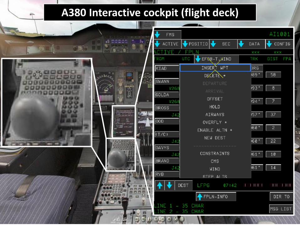
7A380 Interactive cockpit (flight deck)
DU: Display Unit
KCCU: Keyboard and Cursor Control Unit
CDS : Control and Display System
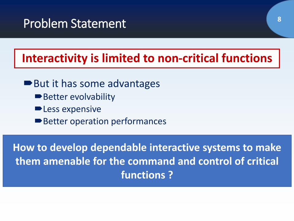
Interactivity is limited to non-critical functions
8Problem Statement
How to develop dependable interactive systems to make them amenable for the command and control of critical
functions ?
But it has some advantagesBetter evolvabilityLess expensiveBetter operation performances
Interactivity is limited to non-critical functions
9Outline of the talk
Introduction and Problem Statement
Context (Interactive Cockpits)
Proposed Approach for Dependable Interactive
Systems/Cockpits
Case Study
Conclusions and Perspectives
10
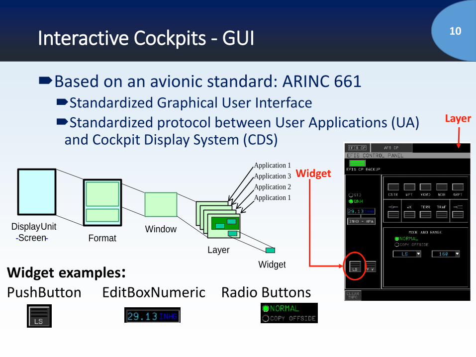
Display Unit - Screen -
Window
Layer
Widget
Format
Application 1
Application 3
Application 2
Application 1
Interactive Cockpits - GUI
Based on an avionic standard: ARINC 661Standardized Graphical User InterfaceStandardized protocol between User Applications (UA)
and Cockpit Display System (CDS)
Widget examples:PushButton EditBoxNumeric Radio Buttons
Widget
Layer
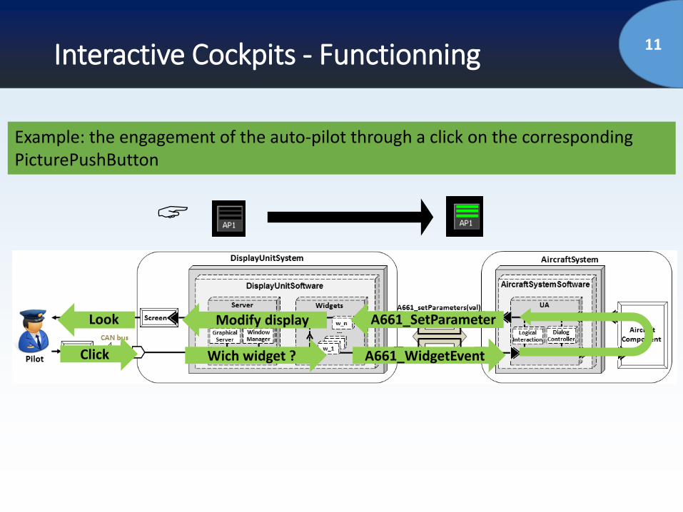
11Interactive Cockpits - Functionning
Example: the engagement of the auto-pilot through a click on the corresponding PicturePushButton
A661_WidgetEvent
A661_SetParameter
Wich widget ?
Modify display
Click
Look
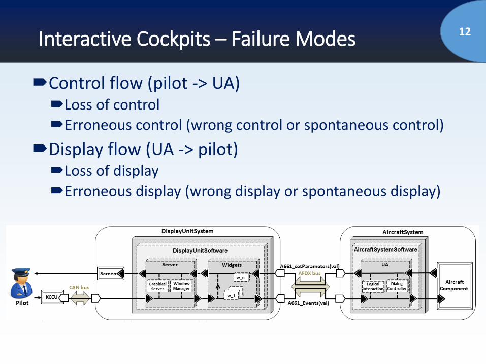
12Interactive Cockpits – Failure Modes
Control flow (pilot -> UA)Loss of controlErroneous control (wrong control or spontaneous control)
Display flow (UA -> pilot)Loss of displayErroneous display (wrong display or spontaneous display)
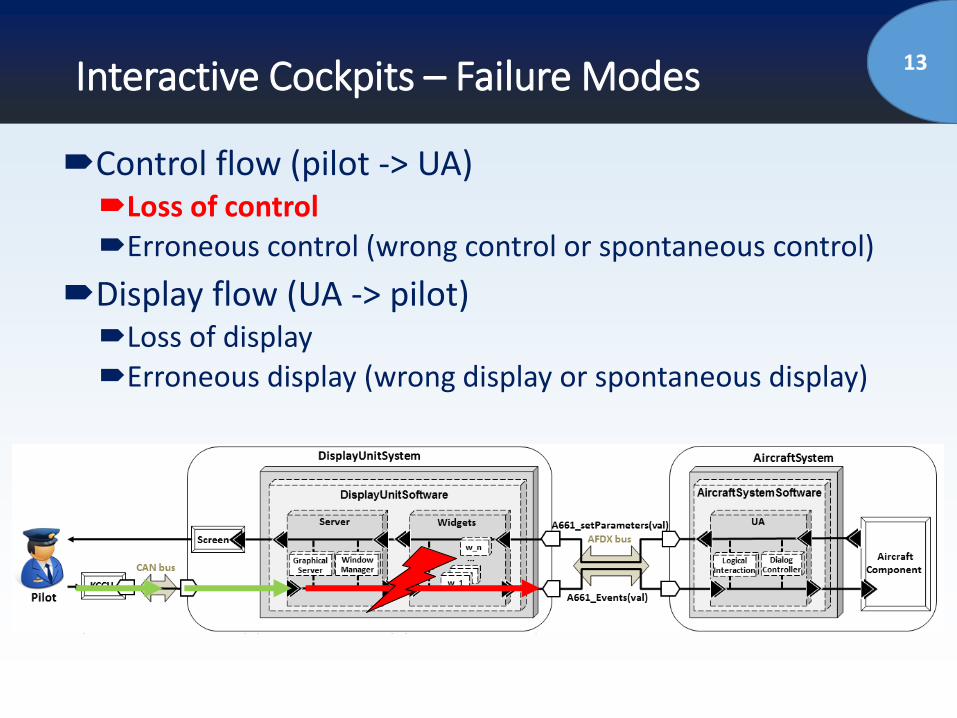
13Interactive Cockpits – Failure Modes
Control flow (pilot -> UA)Loss of controlErroneous control (wrong control or spontaneous control)
Display flow (UA -> pilot)Loss of displayErroneous display (wrong display or spontaneous display)
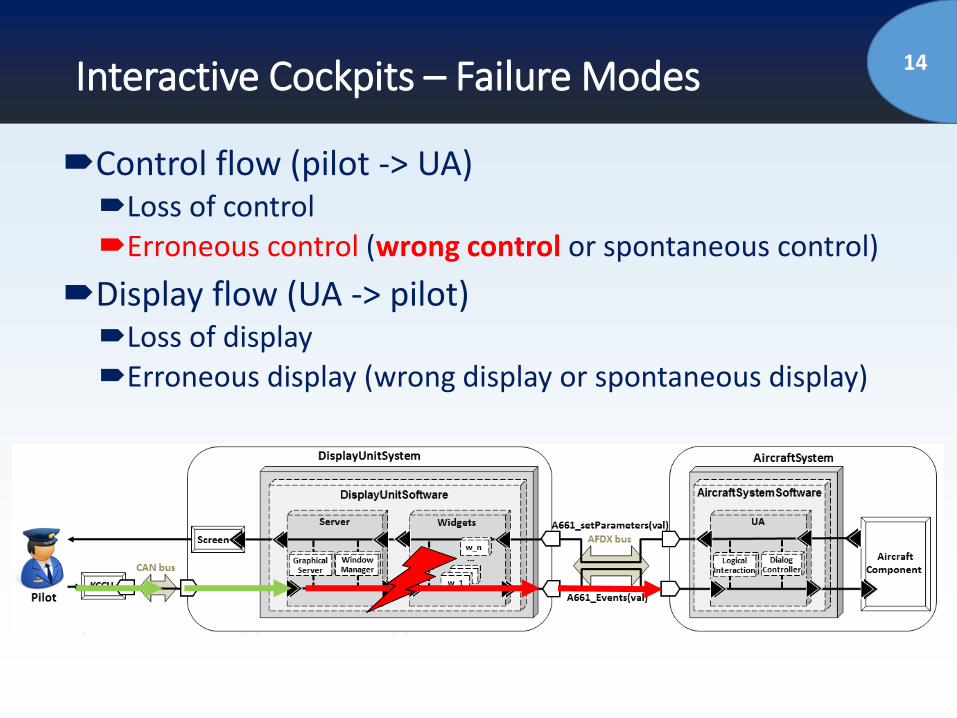
14Interactive Cockpits – Failure Modes
Control flow (pilot -> UA)Loss of controlErroneous control (wrong control or spontaneous control)
Display flow (UA -> pilot)Loss of displayErroneous display (wrong display or spontaneous display)
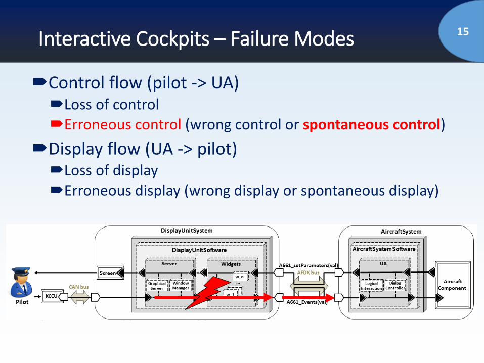
15Interactive Cockpits – Failure Modes
Control flow (pilot -> UA)Loss of controlErroneous control (wrong control or spontaneous control)
Display flow (UA -> pilot)Loss of displayErroneous display (wrong display or spontaneous display)
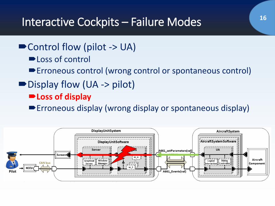
16Interactive Cockpits – Failure Modes
Control flow (pilot -> UA)Loss of controlErroneous control (wrong control or spontaneous control)
Display flow (UA -> pilot)Loss of displayErroneous display (wrong display or spontaneous display)
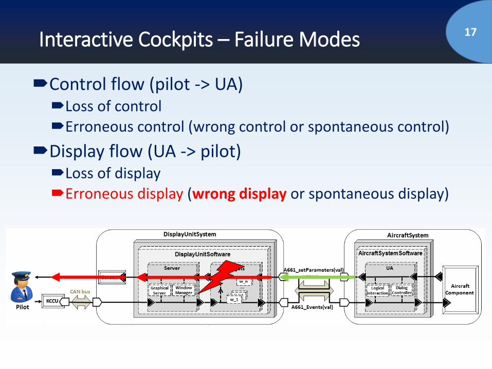
17Interactive Cockpits – Failure Modes
Control flow (pilot -> UA)Loss of controlErroneous control (wrong control or spontaneous control)
Display flow (UA -> pilot)Loss of displayErroneous display (wrong display or spontaneous display)

18Interactive Cockpits – Failure Modes
Control flow (pilot -> UA)Loss of controlErroneous control (wrong control or spontaneous control)
Display flow (UA -> pilot)Loss of displayErroneous display (wrong display or spontaneous display)
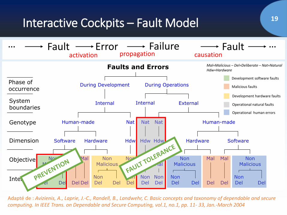
19Interactive Cockpits – Fault Model
Faults and Errors
Phase of occurrence
System boundaries
Genotype
Dimension
Objective
Intent
Software Hardware Hdw Hardware Software
Human-made Human-madeNat
Internal Internal External
During Development During Operations
Mal=Malicious – Del=Deliberate – Nat=NaturalHdw=Hardware
NonDel Del Del Del
NonDel Del
NonDel
NonMalicious
NonMalicious
MalMal NonMal
Hdw Hdw
Nat Nat
NonDel
NonDel
NonMal
NonMal
NonMalicious
DelNonDel
NonDelDel Del
NonMalicious
Mal Mal
Del
Development software faults
Malicious faults
Operational natural faults
Operational human errors
Development hardware faults
Adapté de : Avizienis, A., Laprie, J.-C., Randell, B., Landwehr, C. Basic concepts and taxonomy of dependable and secure computing. In IEEE Trans. on Dependable and Secure Computing, vol.1, no.1, pp. 11- 33, Jan.-March 2004
…propagation causationactivation
Error FailureFault Fault …
20Outline of the talk
Introduction and Problem Statement
Context (Interactive Cockpits)
Proposed Approach for Dependable Interactive
Systems/Cockpits
Case Study
Conclusions and Perspectives
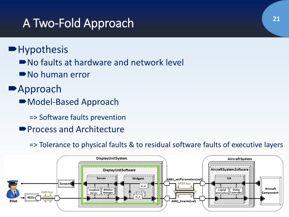
21A Two-Fold Approach
HypothesisNo faults at hardware and network levelNo human error
ApproachModel-Based Approach
=> Software faults prevention
Process and Architecture
=> Tolerance to physical faults & to residual software faults of executive layers
22Outline of the talk
Introduction and Problem Statement
Context (Interactive Cockpits)
Proposed Approach for Dependable Interactive
Systems/Cockpits
Model-Based Development
Process and Architecture
Case Study
Conclusions and Perspectives
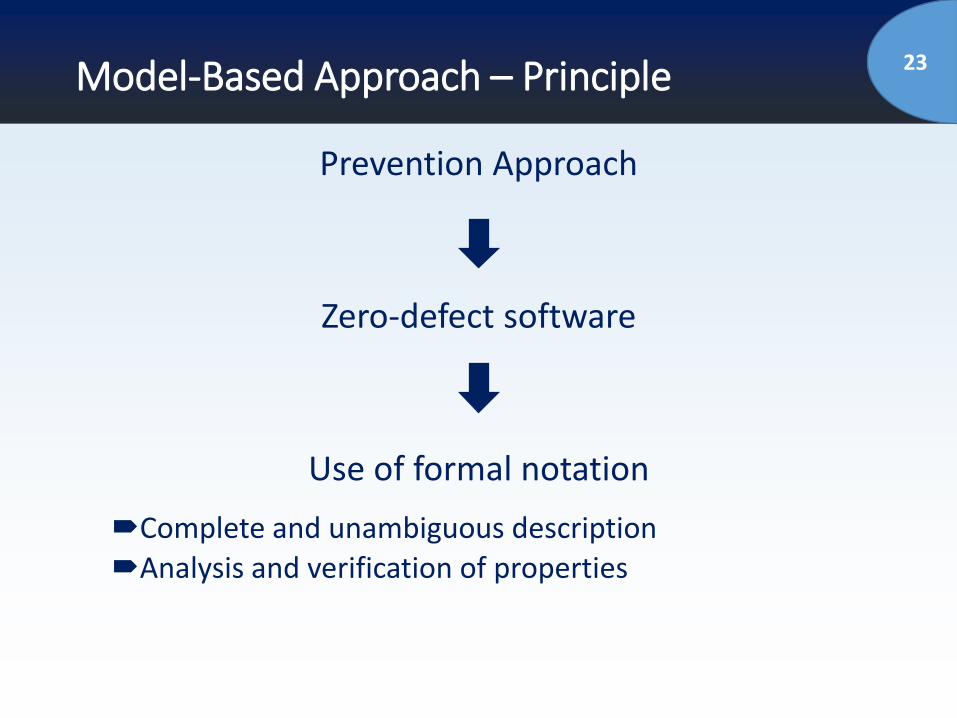
23Model-Based Approach – Principle
Prevention Approach
Zero-defect software
Use of formal notation
Complete and unambiguous descriptionAnalysis and verification of properties
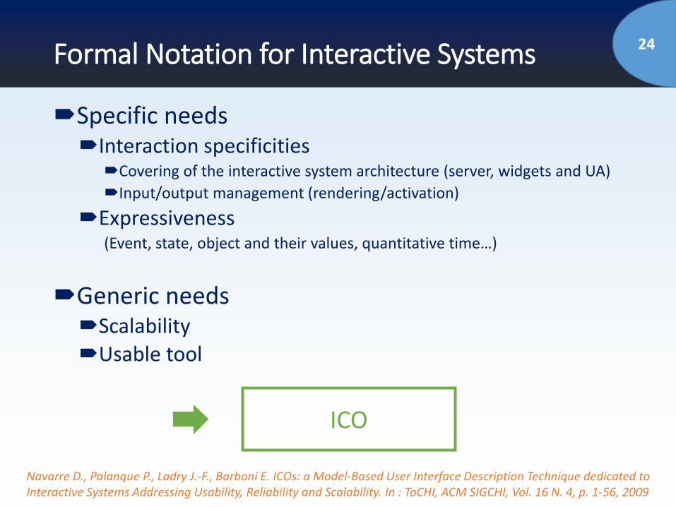
24Formal Notation for Interactive Systems
Navarre D., Palanque P., Ladry J.-F., Barboni E. ICOs: a Model-Based User Interface Description Technique dedicated to Interactive Systems Addressing Usability, Reliability and Scalability. In : ToCHI, ACM SIGCHI, Vol. 16 N. 4, p. 1-56, 2009
Specific needsInteraction specificities
Covering of the interactive system architecture (server, widgets and UA)
Input/output management (rendering/activation)
Expressiveness(Event, state, object and their values, quantitative time…)
Generic needsScalabilityUsable tool
ICO
25ICO (Interactive Cooperative Objects)
Formal notation for interactive systems
High-level Petri nets for behavioral description
Expressiveness
Tool support (PetShop)Model editionAnalysis meansModels execution and simulation

26ICO description of the architecture components
Server
Widget instanciation
SceneGraph
Picking
UA
Application behaviour
FCU Backup
Widgets
Parameters
Events
Formalization of SceneGraph and Picking componentsEnables verification, validation, application of fault tolerant approach (e.g. for detecting overlapping widgets at execution)
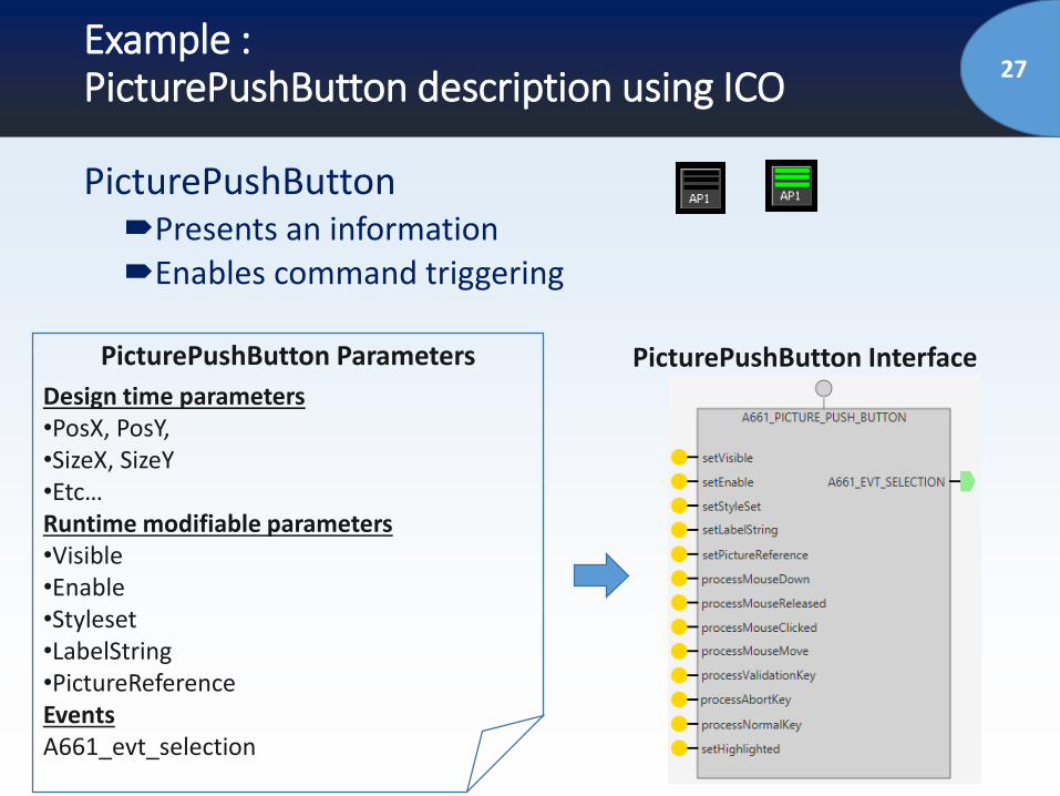
27Example : PicturePushButton description using ICO
PicturePushButtonPresents an informationEnables command triggering
PicturePushButton Parameters
Design time parameters•PosX, PosY, •SizeX, SizeY•Etc…Runtime modifiable parameters•Visible•Enable •Styleset•LabelString•PictureReferenceEventsA661_evt_selection
PicturePushButton Interface
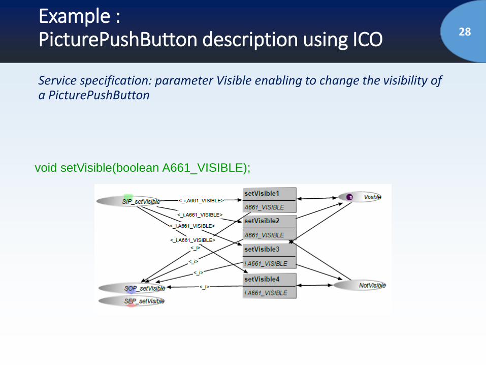
28Example : PicturePushButton description using ICO
Service specification: parameter Visible enabling to change the visibility of a PicturePushButton
void setVisible(boolean A661_VISIBLE);

29Example : PicturePushButton description using ICO
35 places and 20 transitions
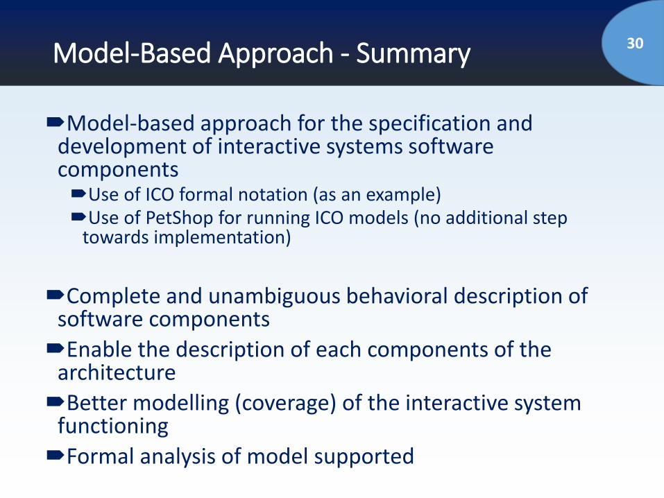
30Model-Based Approach - Summary
Model-based approach for the specification and development of interactive systems software componentsUse of ICO formal notation (as an example)Use of PetShop for running ICO models (no additional step
towards implementation)
Complete and unambiguous behavioral description of software components
Enable the description of each components of the architecture
Better modelling (coverage) of the interactive system functioning
Formal analysis of model supported
31Outline of the talk
Introduction and Problem Statement
Context (Interactive Cockpits)
Proposed Approach for Dependable Interactive
Systems/Cockpits
Model-Based Development
Process and Architecture
Case Study
Conclusions and Perspectives
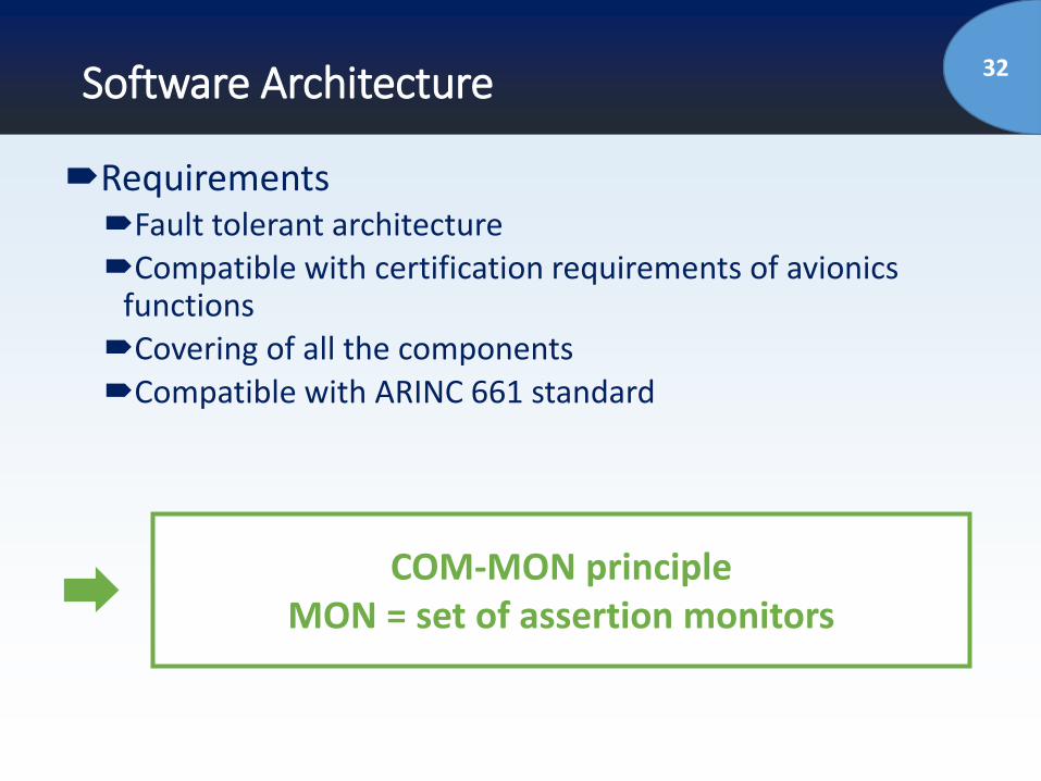
32Software Architecture
RequirementsFault tolerant architectureCompatible with certification requirements of avionics
functionsCovering of all the componentsCompatible with ARINC 661 standard
COM-MON principleMON = set of assertion monitors
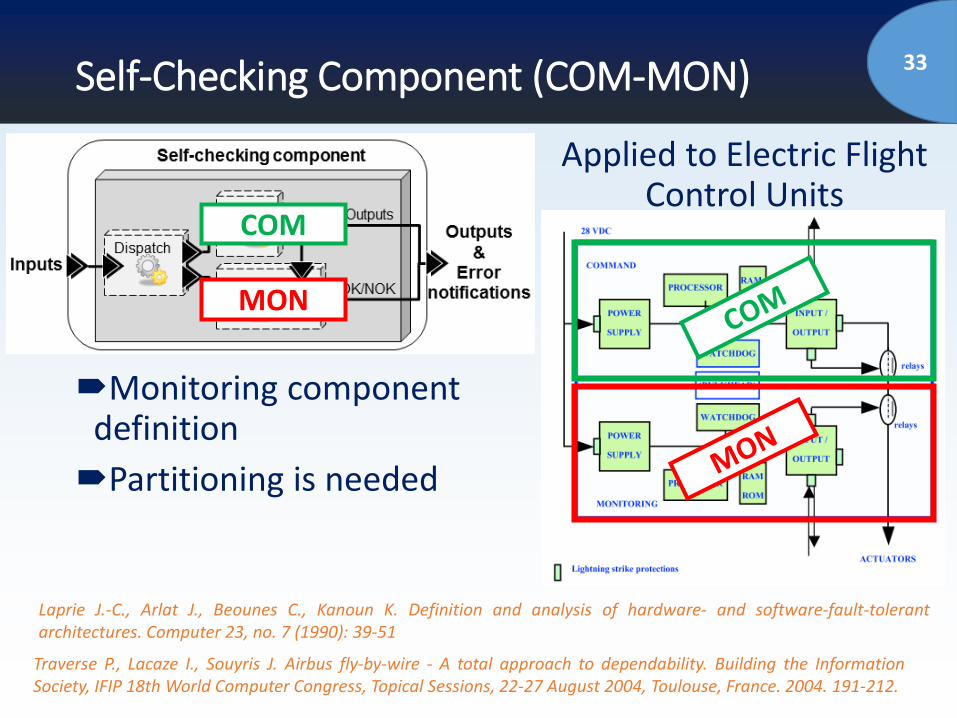
33Self-Checking Component (COM-MON)
Monitoring component definition
Partitioning is needed
Traverse P., Lacaze I., Souyris J. Airbus fly-by-wire - A total approach to dependability. Building the InformationSociety, IFIP 18th World Computer Congress, Topical Sessions, 22-27 August 2004, Toulouse, France. 2004. 191-212.
Laprie J.-C., Arlat J., Beounes C., Kanoun K. Definition and analysis of hardware- and software-fault-tolerantarchitectures. Computer 23, no. 7 (1990): 39-51
COM
MON
Applied to Electric Flight Control Units
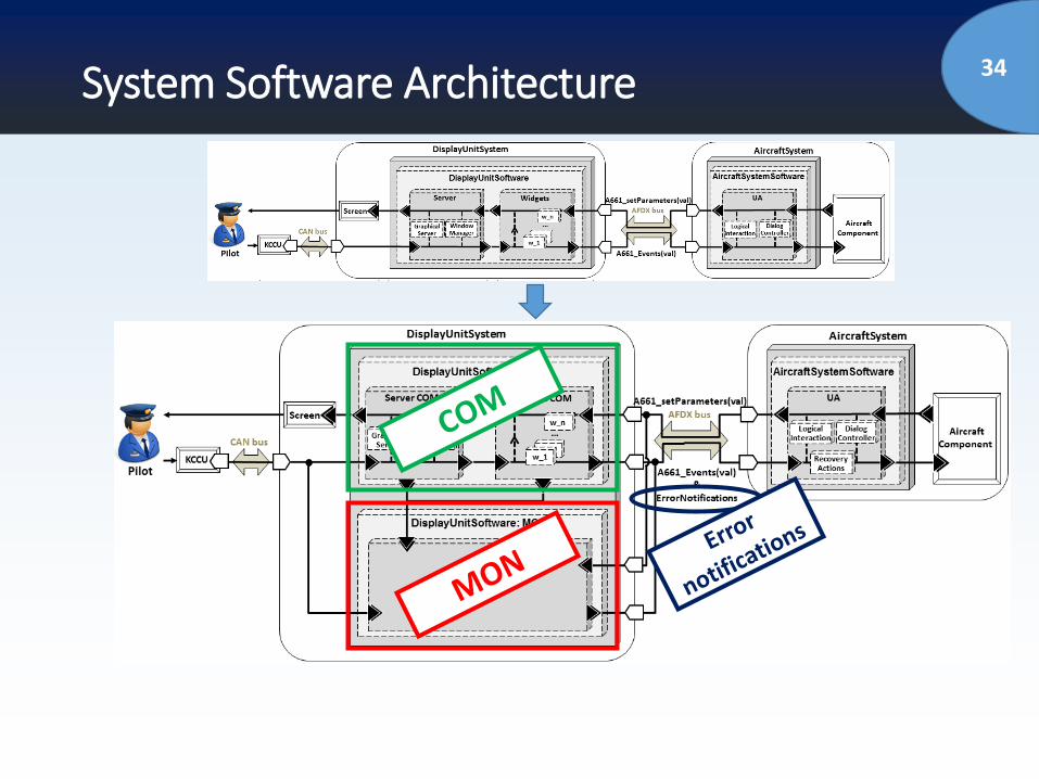
34System Software Architecture
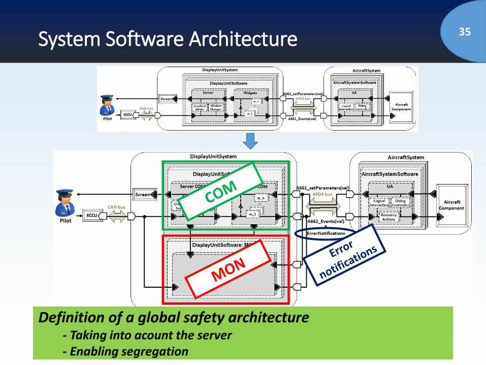
35System Software Architecture
Definition of a global safety architecture- Taking into acount the server- Enabling segregation
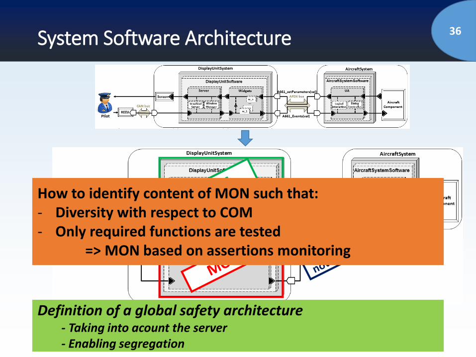
36System Software Architecture
Definition of a global safety architecture- Taking into acount the server- Enabling segregation
How to identify content of MON such that:- Diversity with respect to COM- Only required functions are tested
=> MON based on assertions monitoring
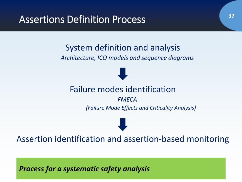
37Assertions Definition Process
System definition and analysisArchitecture, ICO models and sequence diagrams
Failure modes identificationFMECA
(Failure Mode Effects and Criticality Analysis)
Assertion identification and assertion-based monitoring
Process for a systematic safety analysis
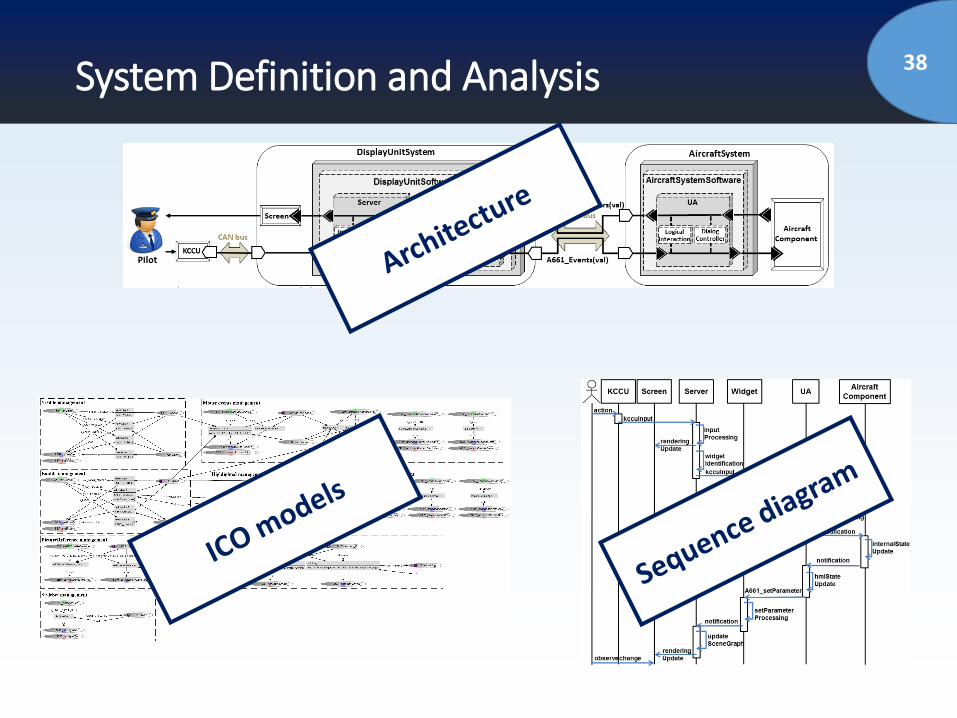
38System Definition and Analysis
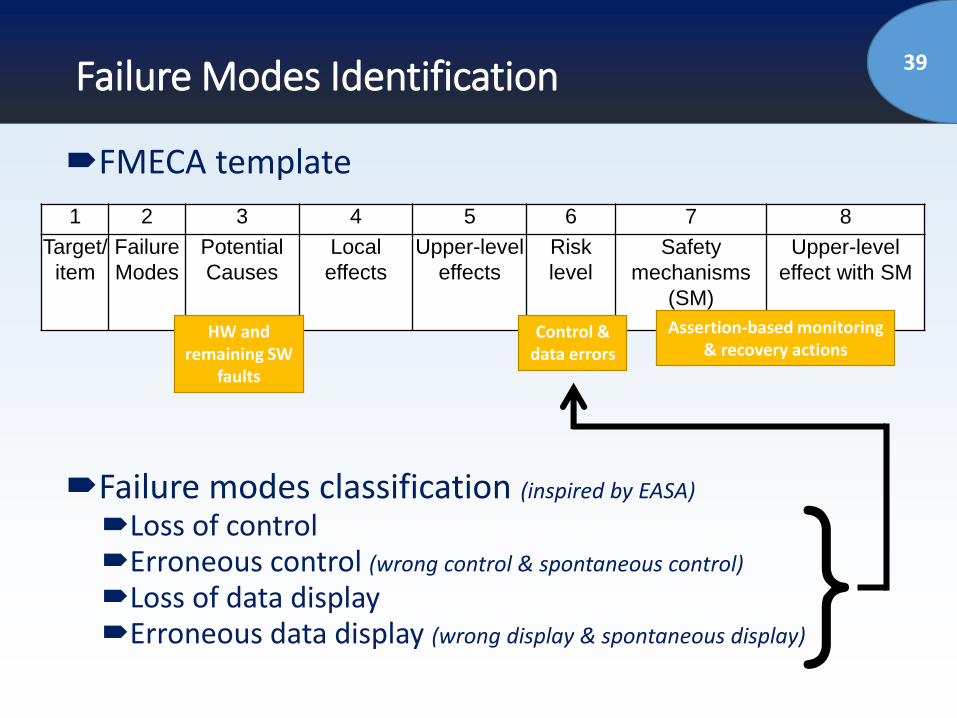
39Failure Modes Identification
FMECA template
Failure modes classification (inspired by EASA)
Loss of controlErroneous control (wrong control & spontaneous control)
Loss of data displayErroneous data display (wrong display & spontaneous display)
1 2 3 4 5 6 7 8
Target/
item
Failure
Modes
Potential
Causes
Local
effects
Upper-level
effects
Risk
level
Safety
mechanisms
(SM)
Upper-level
effect with SM
}
HW and remaining SW
faults
Control & data errors
Assertion-based monitoring & recovery actions
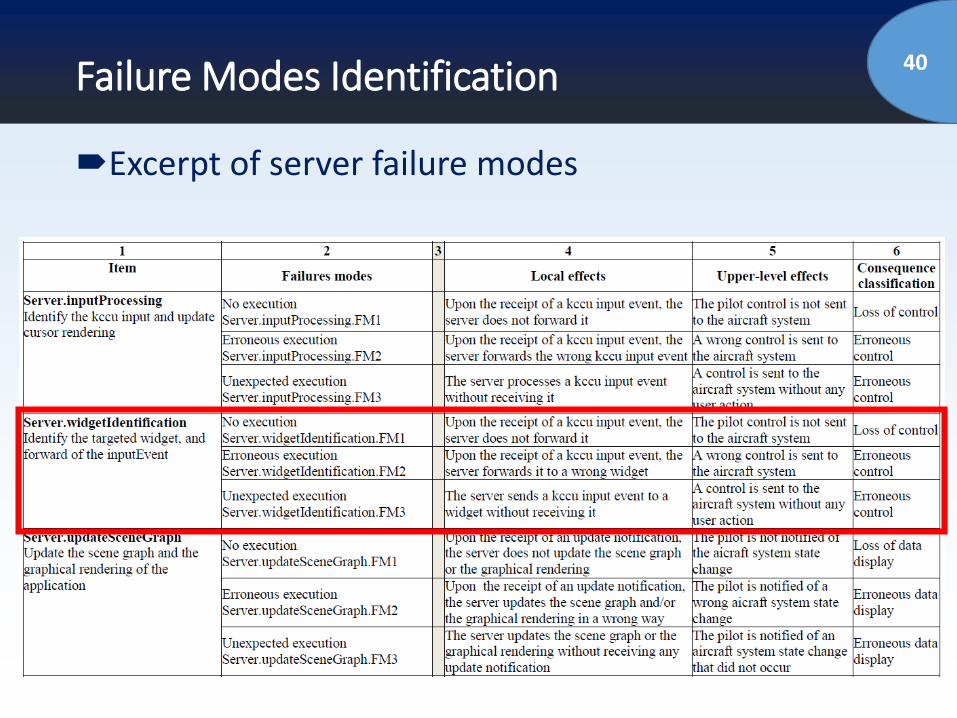
40Failure Modes Identification
Excerpt of server failure modes
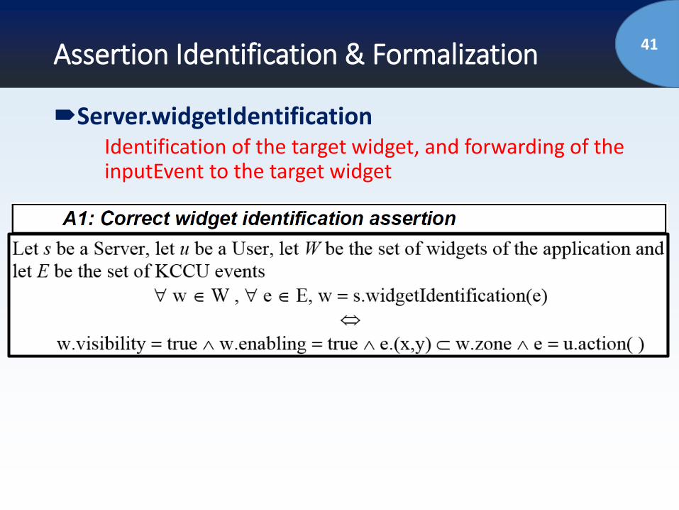
41Assertion Identification & Formalization
Server.widgetIdentificationIdentification of the target widget, and forwarding of the inputEvent to the target widget
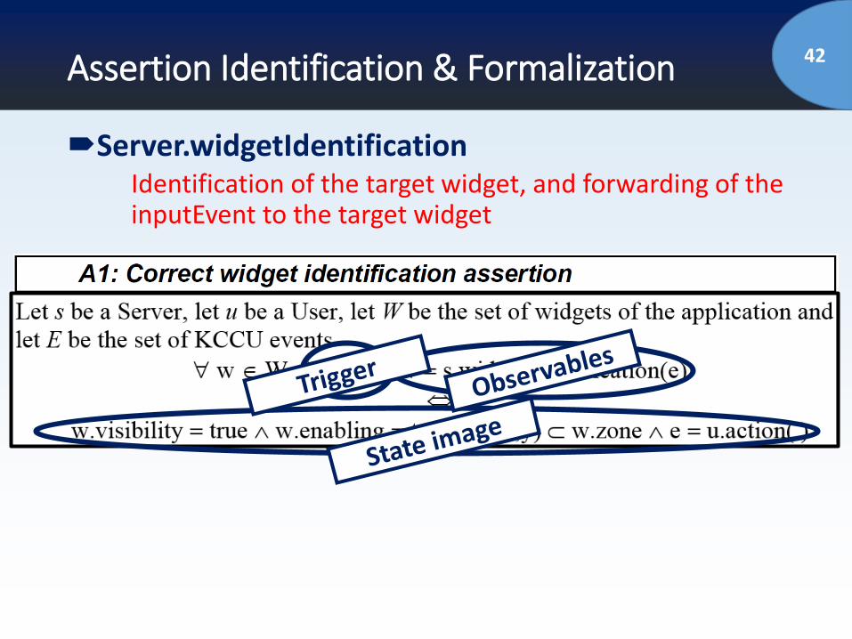
42Assertion Identification & Formalization
Server.widgetIdentificationIdentification of the target widget, and forwarding of the inputEvent to the target widget
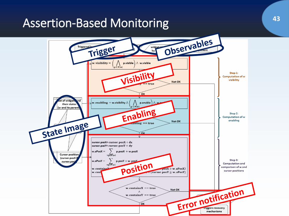
43Assertion-Based Monitoring
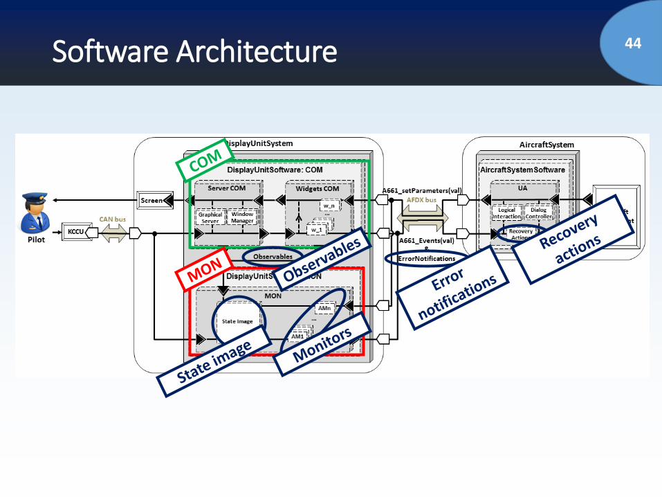
44Software Architecture
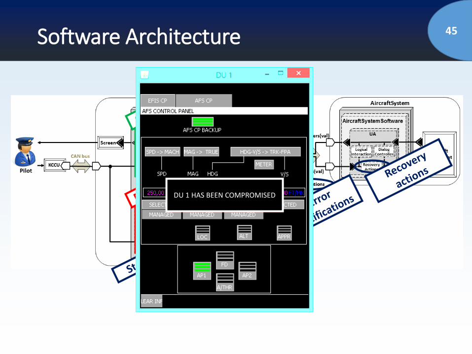
45Software Architecture
DU 1 HAS BEEN COMPROMISED
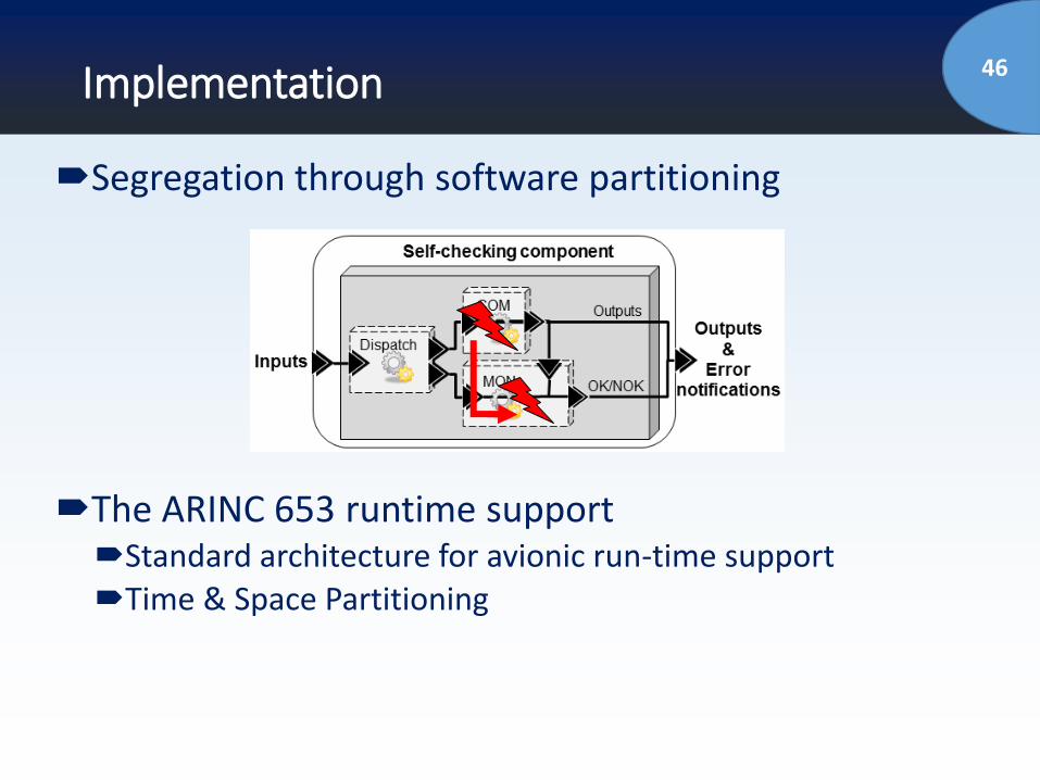
46Implementation
Segregation through software partitioning
The ARINC 653 runtime supportStandard architecture for avionic run-time supportTime & Space Partitioning
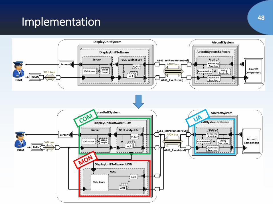
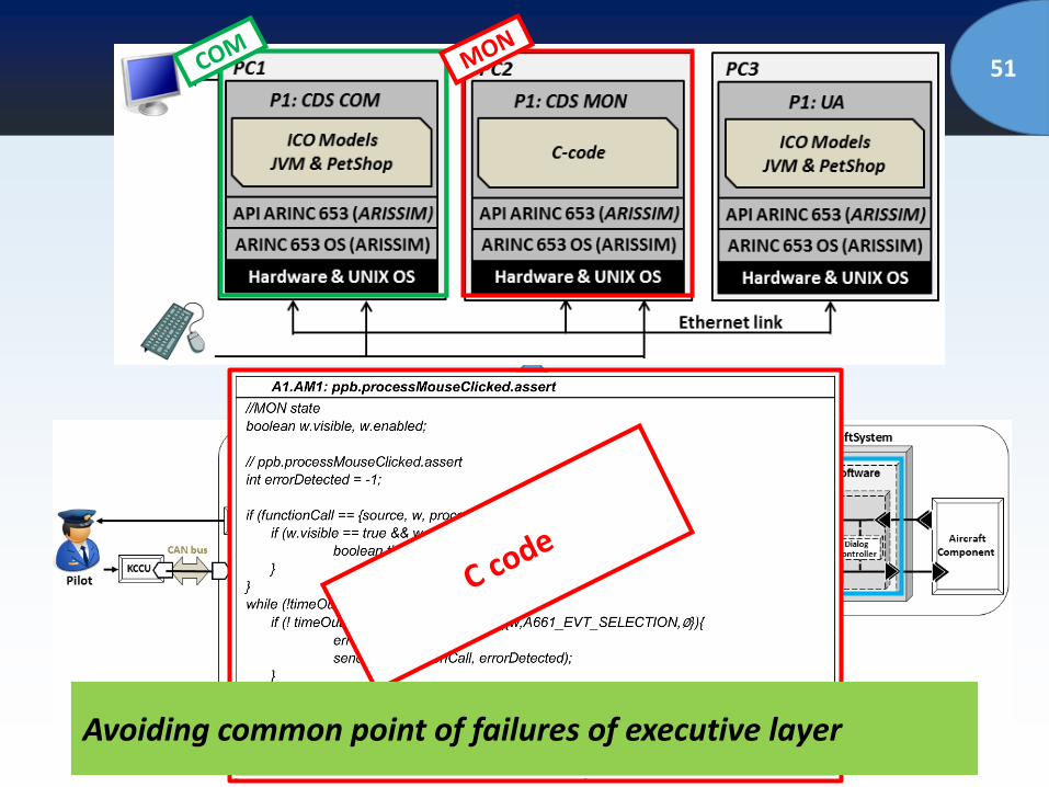
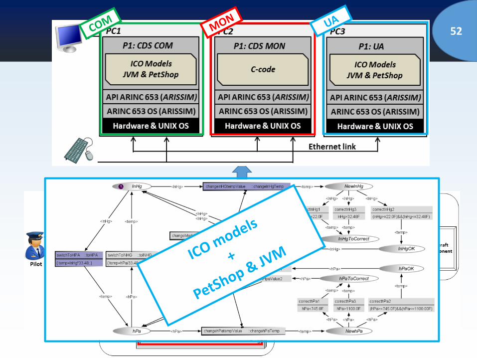
48Implementation
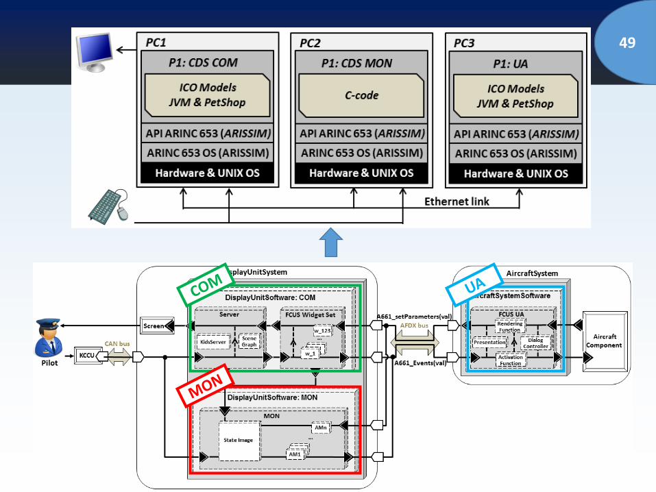
49
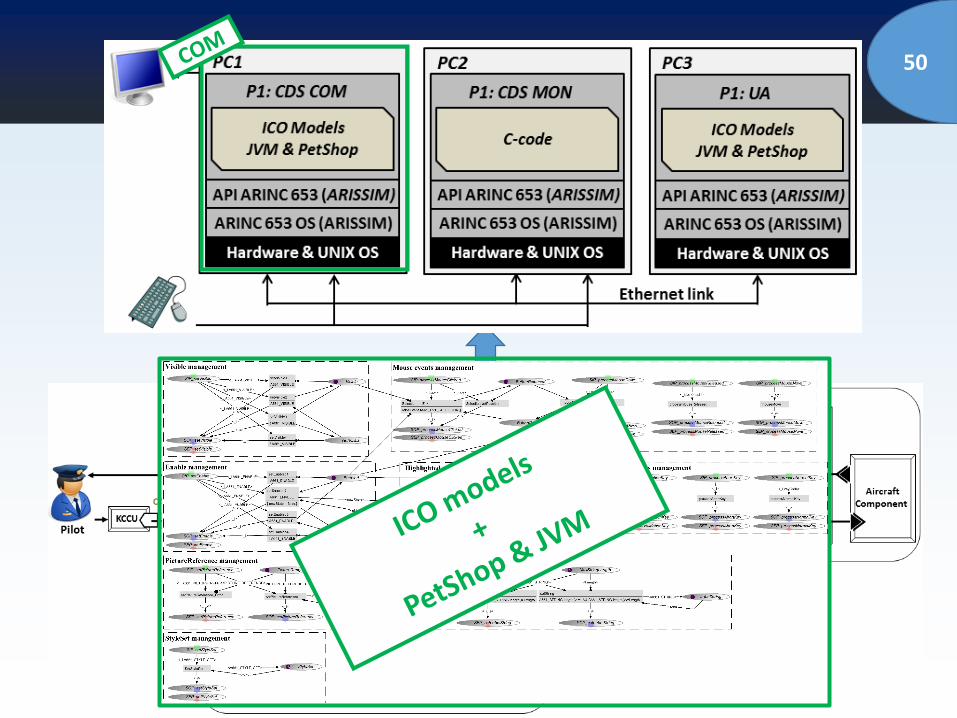
50
51
Avoiding common point of failures of executive layer
52
53Process and Architecture - Summary
Global fault tolerant system architectureFault detection using COM-MON principlesApplied to the generic part (the CDS)
Assertion definition processSafety analysisAssertion formalizationAssertion-based monitors
Implementation principlesBased on ARINC 653 principlesDevelopment of an ARINC 653 simulatorPartitioning of COM and MON components
54Outline of the talk
Introduction and Problem Statement
Context (Interactive Cockpits)
Proposed Approach for Dependable Interactive
Systems/Cockpits
Case Study
Conclusions and Perspectives
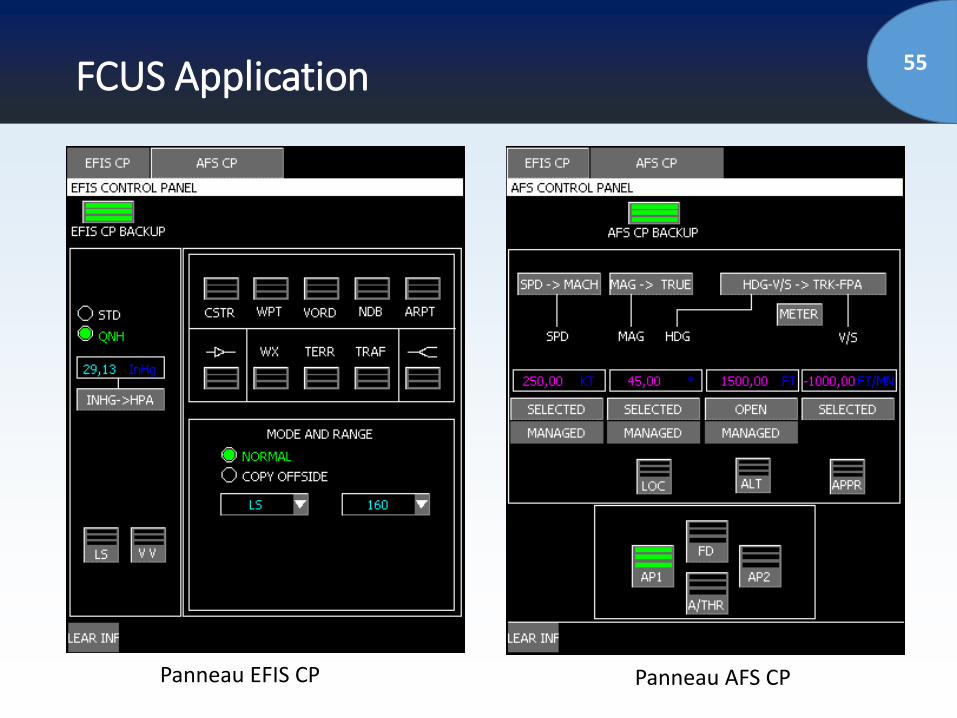
55FCUS Application
Panneau EFIS CP Panneau AFS CP
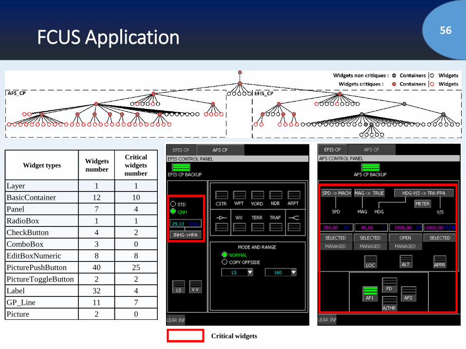
56FCUS Application
Type de widget
Nombre
total de
widgets
Nombre de
widgets
critiques
Layer 1 1
BasicContainer 12 10
Panel 7 4
RadioBox 1 1
CheckButton 4 2
ComboBox 3 0
EditBoxNumeric 8 8
PicturePushButton 40 25
PictureToggleButton 2 2
Label 32 4
GP_Line 11 7
Picture 2 0
Widget typesWidgets
number
Critical
widgets
number
Critical widgets
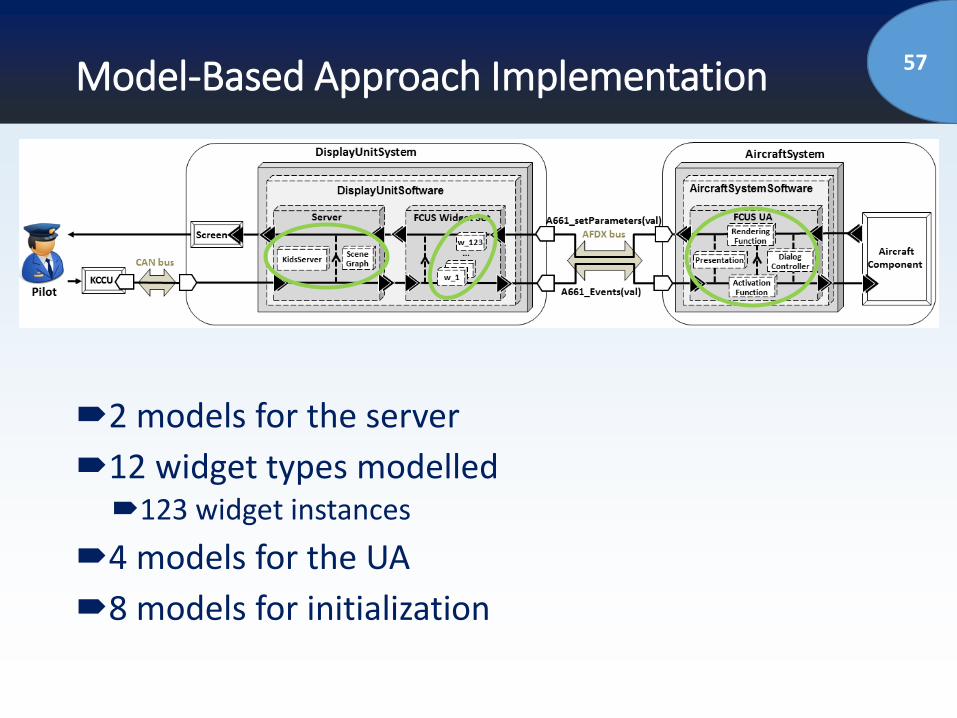
57Model-Based Approach Implementation
2 models for the server
12 widget types modelled123 widget instances
4 models for the UA
8 models for initialization
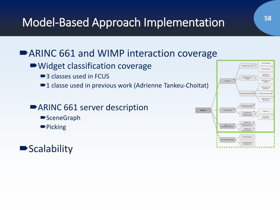
58Model-Based Approach Implementation
ARINC 661 and WIMP interaction coverageWidget classification coverage
3 classes used in FCUS
1 classe used in previous work (Adrienne Tankeu-Choitat)
ARINC 661 server descriptionSceneGraph
Picking
Scalability
WIDGET
ACTION
AFFICHAGE
OBJET DE REGROUPEMENT
AUTOMATISATION
Action sur l’UA
Action sur le widget
Entrée information
Commande
Choix d’Etat
Sélection d’interface
Sélection de widget
Sélection de position
Saisie de données
Sélection de données
Composant textuel de présentation
Composant graphique de présentation
Externe
Primitive graphique
Objet de regroupement non
géographique
Objet de regroupement géographique
Notification
Comportement graphique
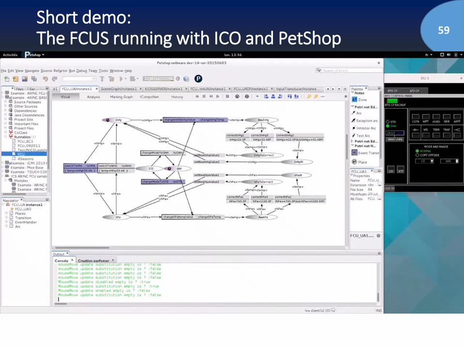
59Short demo:The FCUS running with ICO and PetShop
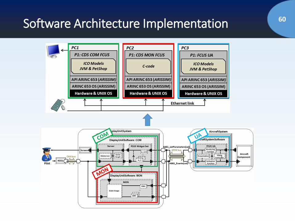
60Software Architecture Implementation
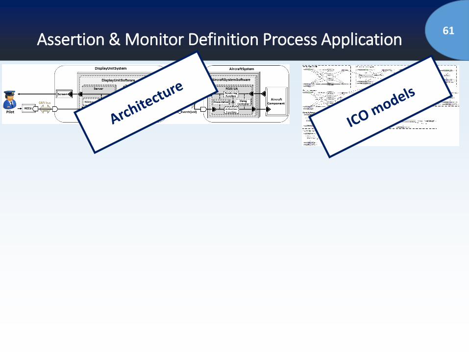
61Assertion & Monitor Definition Process Application
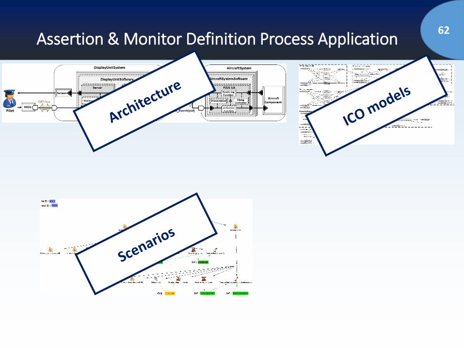
62Assertion & Monitor Definition Process Application
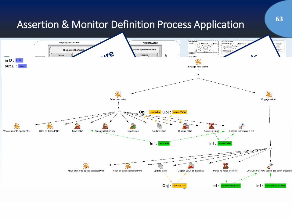
63Assertion & Monitor Definition Process Application
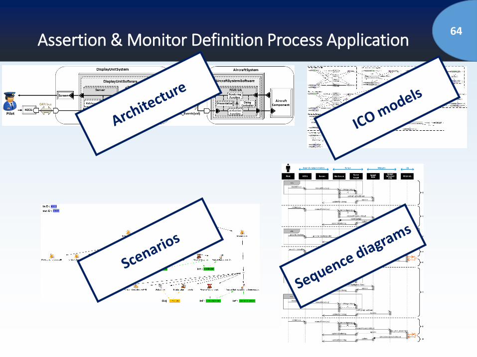
64Assertion & Monitor Definition Process Application
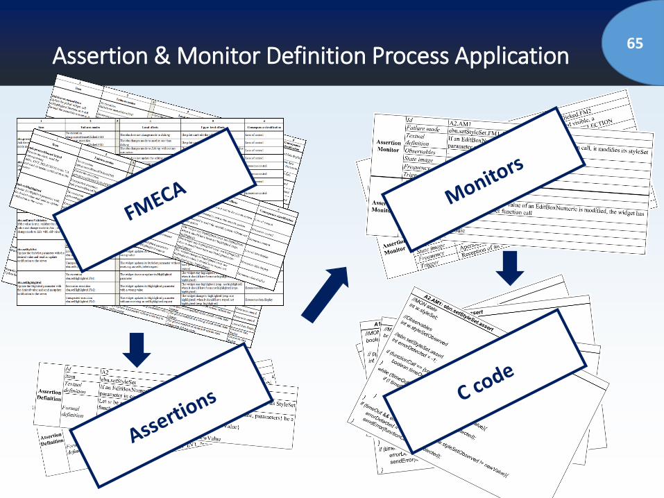
65Assertion & Monitor Definition Process Application
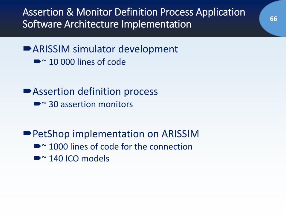
66Assertion & Monitor Definition Process ApplicationSoftware Architecture Implementation
ARISSIM simulator development~ 10 000 lines of code
Assertion definition process~ 30 assertion monitors
PetShop implementation on ARISSIM~ 1000 lines of code for the connection~ 140 ICO models
67Outline of the talk
Introduction and Problem Statement
Context (Interactive Cockpits)
Proposed Approach for Dependable Interactive
Systems/Cockpits
Case Study
Conclusions and Perspectives
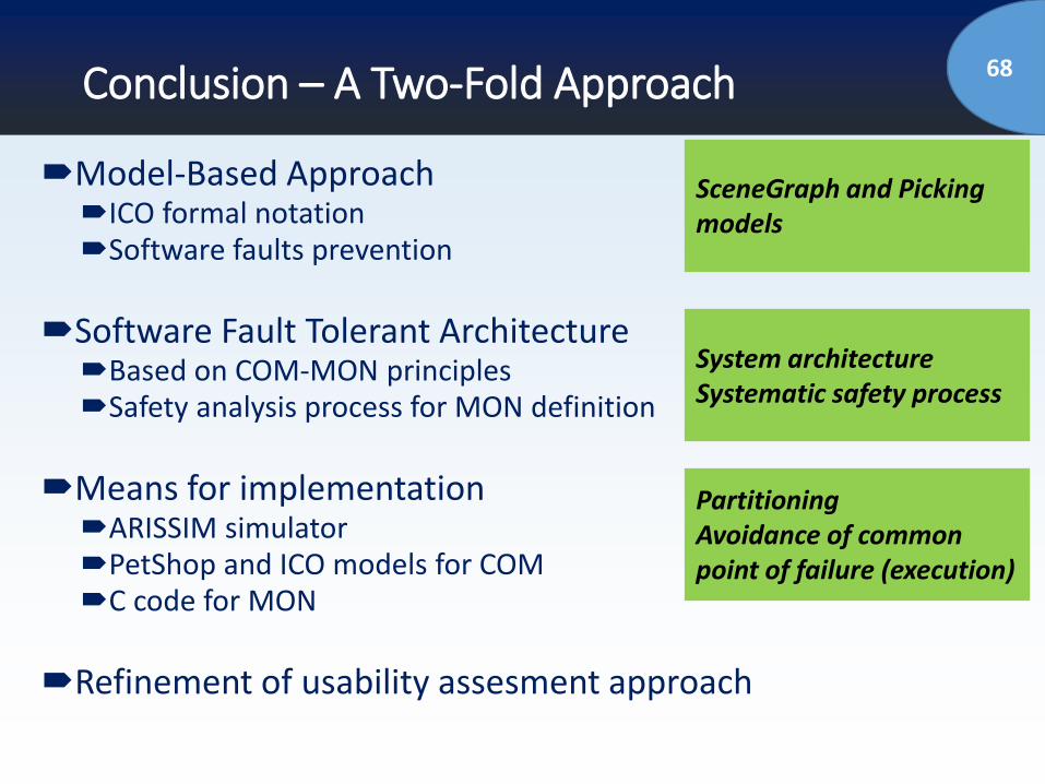
68Conclusion – A Two-Fold Approach
Model-Based ApproachICO formal notationSoftware faults prevention
Software Fault Tolerant ArchitectureBased on COM-MON principlesSafety analysis process for MON definition
Means for implementationARISSIM simulatorPetShop and ICO models for COMC code for MON
Refinement of usability assesment approach
SceneGraph and Picking models
System architectureSystematic safety process
PartitioningAvoidance of commonpoint of failure (execution)
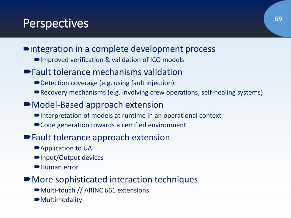
69Perspectives
Integration in a complete development processImproved verification & validation of ICO models
Fault tolerance mechanisms validationDetection coverage (e.g. using fault injection)
Recovery mechanisms (e.g. involving crew operations, self-healing systems)
Model-Based approach extension Interpretation of models at runtime in an operational context
Code generation towards a certified environment
Fault tolerance approach extensionApplication to UA
Input/Output devices
Human error
More sophisticated interaction techniquesMulti-touch // ARINC 661 extensions
Multimodality
7070
Thank you for your attention!
Questions ?