Toward Fully Automated Person-Independent Detection of Mind Wandering

Chapter 8
TOWARD AUTOMATED DESIGN OF INDUSTRIAL-STRENGTH ANALOG CIRCUITS BY MEANS OF GENETIC PROGRAMMING
John R. Koza1, Lee W. Jones2, Martin A. Keane3, Matthew J. Streeter4 and Sameer H. Al-Sakran2 1Stanford University, Stanford, California; 2Genetic Programming Inc., Mountain View, California; 3Econometrics Inc., Chicago, Illinois; 4Carnegie Mellon University, Pittsburgh, Pennsylvania.
Abstract: It has been previously established that genetic programming can be used as an automated invention machine to synthesize designs for complex structures. In particular, genetic programming has automatically synthesized structures that infringe, improve upon, or duplicate the functionality of 21 previously patented inventions (including six 21st-century patented analog electrical circuits) and has also generated two patentable new inventions (controllers). There are seven promising factors suggesting that these previous results can be extended to deliver industrial-strength automated design of analog circuits, but two countervailing factors. This chapter explores the question of whether the seven promising factors can overcome the two countervailing factors by reviewing progress on an ongoing project in which we are employing genetic programming to synthesize an amplifier circuit. The work involves a multiobjective fitness measure consisting of 16 different elements measured by five different test fixtures. The chapter describes five ways of using general domain knowledge applicable to all analog circuits, two ways for employing problem-specific knowledge, four ways of improving on previously published genetic programming techniques, and four ways of grappling with the multi-objective fitness measures associated with real-world design problems.
Key words: Automated design, automated circuit synthesis, analog circuits, amplifier, evolvable hardware, developmental process, genetic programming

122 GENETIC PROGRAMMING THEORY AND PRACTICE II 1. INTRODUCTION
Genetic programming is an automatic method for solving problems. It is an extension of the genetic algorithm (Holland 1975). Genetic programming starts from a high-level statement of the requirements of a problem and attempts to automatically create a computer program that solves the problem. Specifically, genetic programming starts with a primordial ooze of thousands of randomly created computer programs and uses the Darwinian principle of natural selection (fitness-based selection); analogs of recombination (crossover), mutation, gene duplication, gene deletion; and certain mechanisms of developmental biology to progressively breed an improved population over a series of generations (Koza 1992, Koza 1994; Koza, Bennett, Andre, and Keane 1999; Koza, Keane, Streeter, Mydlowec, Yu, and Lanza 2003; Banzhaf, Nordin, Keller, and Francone 1998; Langdon and Poli 2002).
Genetic programming can be used as an automated invention machine to synthesize designs for complex structures. In particular, genetic programming has automatically synthesized complex structures that infringe, improve upon or duplicate in a novel way the functionality of 21 previously patented inventions (e.g., analog electrical circuits, controllers, and mathematical algorithms), including six post-2000 patented inventions. These 21 patented inventions are listed in Table 8.14.1 of (Koza, Streeter, and Keane 2003). In addition, genetic programming has generated two patentable new inventions (both controllers) for which patent applications are currently pending (Keane, Koza, and Streeter 2002). Genetic programming has also generated numerous additional human-competitive results involving the automated design of quantum computing circuits (Spector 2004) and antennae (Lohn, Hornby, and Linden 2004). Genetic programming has generated results involving the automated design of networks of chemical reactions and metabolic networks (Koza, Mydlowec, Lanza, Yu, and Keane 2001) and genetic networks (Lanza, Mydlowec, and Koza 2000).
The six 21st-century patented inventions that were re-created by genetic programming were analog electrical circuits. Automatic synthesis of analog circuits from high-level specifications has long been recognized as a challenging problem. As Aaserud and Nielsen (1995) noted:
“[M]ost … analog circuits are still handcrafted by the experts or so-called ‘zahs’ of analog design. The design process is characterized by a combination of experience and intuition and requires a thorough knowledge of the process characteristics and the detailed specifications of the actual product.

Toward Automated Design of Analog Circuits by GP 123
“Analog circuit design is known to be a knowledge-intensive, multiphase, iterative task, which usually stretches over a significant period of time and is performed by designers with a large portfolio of skills. It is therefore considered by many to be a form of art rather than a science.”
And, as Balkir, Dundar, and Ogrenci (2003) stated: “The major reason underlying this lack of analog design automation tools has been the difficulty of the problem, in our opinion. Design in the analog domain requires creativity because of the large number of free parameters and the sometimes obscure interactions between them. … Thus, analog design has remained more of an ‘art’ than a ‘science.’ ”
There are seven promising factors suggesting that the previous results can be extended to deliver industrial-strength automated design of analog circuits and there are two countervailing factors that impede progress.
One promising factor is the unusually high success rate of previous work. Multiple runs of a probabilistic algorithm are typically necessary to solve a non-trivial problem. However, all 11 runs involving the six post-2000 patented circuits (ignoring partial runs used during debugging) yielded a satisfactory solution. This high rate suggests that we are currently nowhere near the limit of the capability of existing techniques.
A second promising factor (discussed in section 2) is that genetic programming has historically demonstrated the ability to yield progressively more substantial results in synchrony with the relentless increase in computer power tracked by Moore’s law (thereby suggesting that evermore complex problems can be solved as increased computer power becomes available).
A third promising factor (discussed in section 3) is that our previous work (and most other previous work) involving the automated synthesis of circuits intentionally ignored many pieces of elementary general domain knowledge about analog circuits. For example, none of our previous runs culled egregiously flawed circuits, such as those drawing enormous amounts of current or those that lacked a connection to the circuit’s incoming signal, output port, or power supplies. Instead, our previous work approached each problem with a relatively “clean hands” orientation—using as little human-supplied domain knowledge about electrical circuits as possible. Although this “clean hands” orientation highlighted the ability of genetic programming to produce human-competitive results in a “clean hands” setting, this orientation is entirely irrelevant to a practicing engineer interested in designing real-world circuits.
A fourth promising factor (discussed in section 4) is that our previous work (and most other previous work) intentionally ignored opportunities to employ problem-specific knowledge about the to-be-designed circuit. For

124 GENETIC PROGRAMMING THEORY AND PRACTICE II example, the starting point for circuit development in our previous runs usually consisted merely of a single modifiable wire. Genetic programming was then expected to automatically create the entire circuit from scratch. However, a practicing engineer does not start each new assignment from first principles. Instead, the starting point for real-world design typically incorporates a core substructure that is known to provide a good head start.
A fifth promising factor (also discussed in section 4) is that the genetic programming techniques used in our previous work to produce the six post-2000 patented circuits were intentionally rigidly uniform. This uniformity had the advantage of emphasizing the ability of genetic programming to produce human-competitive results in a relatively “clean hands” setting. For example, we did not use automatically defined functions (subroutines) even on problems with manifest parallelism, regularity, symmetry, and modularity. However, a practicing engineer does not “reinvent the wheel” on each occasion requiring an already known solution to a sub-problem.
A sixth promising factor (discussed in section 5) is that current techniques used for circuit synthesis can be improved by applying various aspects of the theory of genetic algorithms and genetic programming. Many of the current techniques go back to early work on automated circuit synthesis and have not been critically reexamined since then.
A seventh promising factor is that considerable work has been done in recent years to accelerate the convergence characteristics and general efficiency of circuit simulators. For example, we used a version of the SPICE3 simulator (Quarles, Newton, Pederson, and Sangiovanni-Vincentelli 1994) that we modified in various ways (as described in Koza, Bennett, Andre, and Keane 1999). Today, there are numerous commercially available simulators that are considerably faster (e.g., up to 10 times faster).
There are, however, at least two countervailing factors that impede progress toward industrial-strength automated design of analog circuits.
The first countervailing factor (discussed in section 6) concerns the multi-objective fitness measures that are typically associated with industrial-strength problems. The fitness measures used in previously published examples of the synthesis of analog circuits by means of genetic programming (and genetic algorithms) typically consist of only a few different elements (rarely as many as four). In contrast, the data sheets used to specify commercial circuits typically contain a dozen or more different performance requirements. It is difficult to quantify the tradeoff between disparate elements of a fitness measure. Moreover, as the number of disparate elements in a fitness measure increases, the strategy for combining the various (“apples and oranges”) elements of the fitness measure usually becomes vexatious. If, for example, gain, bias, and distortion (three characteristics that are relevant to amplifier design) are naively assigned

Toward Automated Design of Analog Circuits by GP 125 equal weight in a fitness measure, an unadorned wire will immediately achieve a very good score (because a wire introduces no distortion and no bias to an incoming circuit). What’s worse, almost any single modification applied to this wire will be highly deleterious—thereby creating a local optimum from which escape is difficult. The search for an amplifier may easily become trapped in an area of the search space containing distortion-free and bias-free circuits that deliver no amplification at all. Thus, the handling of the type of multi-objective fitness measures associated with industrial-strength design problems is a major issue.
The second countervailing factor arises from the need to evaluate candidate circuits at the “corners” of various performance envelopes. For example, circuit behavior depends on temperature. A real-world circuit might be required to operate correctly over a range between, say, –40° C and +105° C, not merely at room temperature (27° C). Separate simulations (or, if reconfigurable hardware is being used, separate test scenarios with different ambient temperatures) are required to measure the circuit’s performance at each corner of the temperature envelope. Each additional simulation multiplies the required computer time by a factor of two (if only the two extreme values are considered), three (if the nominal value and two extremes are considered), or more (if more values are considered because of non-linear behavior). Similarly, a real-world circuit will be expected to operate correctly in the face of variation in the circuit’s power supply (e.g., when the battery or other power supply is delivering, say, 90% or 110% of its nominal voltage). Again, separate simulations are required to measure the circuit’s performance at each voltage corner. In addition, a real-world circuit will be expected to operate correctly in the face of deviations between the behavior of an actual manufactured component and the component’s “model” performance. For example, separate measurements may be required for a entire circuit’s “fast,” “typical,” and “slow” behavior or when a particular component is 75% or 125% of its nominal value. Circuits may also be expected to operate correctly in the face of variations in load, input, or other characteristics.
Thus, the answer to the question as to whether genetic programming can deliver industrial-strength automated design of analog electrical circuits depends on whether the seven promising factors overcome the two countervailing factors.
The remainder of this chapter reports on progress on an ongoing project in which we employed genetic programming to automatically synthesize both the topology and sizing of an amplifier circuit.

126 GENETIC PROGRAMMING THEORY AND PRACTICE II 2. ABILITY OF GENETIC PROGRAMMING TO
PROFITABLY EXPLOIT INCREASED COMPUTER POWER
Genetic programming generally requires significant computational resources to solve non-trivial problems. Fortunately, the computer time necessary to achieve human-competitive results has become increasingly available in recent years because (1) the speed of commercially available single computers continues to double approximately every 18 months in accordance with Moore’s law, (2) genetic programming is amenable to efficient parallelization, and (3) Beowulf-style parallel cluster computer systems can be assembled at relatively low cost.
As shown in Table 8-1, GP has historically demonstrated the ability to yield progressively more substantial results, given the increased computer power tracked by Moore’s law. Column 1 lists the five computer systems used to produce our group’s reported work on GP in the 15-year period between 1987 and 2002. Column 4 shows the speed-up of each system over the system shown in the previous row of the table. Column 7 shows the number of human-competitive results generated by each computer system.
Table 8-1. Human-competitive results produced by GP with five computer systems.
System Period Petacycles
per day Speed-up over
first system Used for work in
book Human-
competitive results
Texas Instruments
LISP machine
1987–1994
0.002 1 (base) Genetic Programming I and II
0
64-node Transtech transputer machine
1994–1997
0.02 9 A few problems in Genetic
Programming III
2
64-node Parsytec machine
1995–2000
0.44 204 Most problems in Genetic
Programming III
12
70-node Alpha
machine
1999–2001
3.2 1,481 8 of problems in Genetic
Programming IV
2
1,000-node Pentium II machine
2000–2002
30.0 13,900 28 of the problems in Genetic
Programming IV
12

Toward Automated Design of Analog Circuits by GP 127
The first entry in Table 8-1 is a serial computer and the next four entries are parallel computer systems. The presence of four increasingly powerful parallel computer systems reflects the fact that genetic programming has successfully taken advantage of the increased computational power available by means of parallel processing.
Table 8-1 shows the following: • There is an order-of-magnitude speed-up (column 3) between each
successive computer system in the table. Note that, according to Moore’s law, exponential increases in computer power correspond approximately to constant periods of time.
• There is a 13,900-to-1 speed-up (column 4) between the fastest and most recent machine (the 1,000-node parallel computer system) and the slowest and earliest machine (the serial LISP machine).
• The slower early machines generated few or no human-competitive results, whereas the faster more recent machines have generated numerous human-competitive results.
Four successive order-of-magnitude increases in computer power are explicitly shown in Table 8-1. An additional order-of-magnitude increase was achieved by making extraordinarily long runs on the largest machine in the table (the 1,000-node Pentium® II parallel machine). The length of the run that produced the genetically evolved controller for which a patent application is currently pending (Keane, Koza, and Streeter 2002) was 28.8 days—almost an order-of-magnitude increase over the 3.4-day average for runs that our group has made in recent years. If this final 9.3-to-1 increase is counted as an additional speed-up, the overall speed-up is 130,660-to-1.
Table 8-2 is organized around the five just-explained order-of-magnitude increases in the expenditure of computing power. Column 4 of this table characterizes the qualitative nature of the results produced by genetic programming. This table shows the progression of qualitatively more substantial results produced by genetic programming in terms of five order-of-magnitude increases in the expenditure of computational resources.
The order-of-magnitude increases in computer power shown in Table 8-2 correspond closely (albeit not perfectly) with the following progression of qualitatively more substantial results produced by genetic programming:
• toy problems, • human-competitive results not related to patented inventions, • 20th-century patented inventions, • 21st-century patented inventions, and • patentable new inventions.

128 GENETIC PROGRAMMING THEORY AND PRACTICE II
The progression in Table 8-2 demonstrates that genetic programming is able to take advantage of the exponentially increasing computational power tracked by iterations of Moore’s law. Table 8-2. Progression of qualitatively more substantial results produced by genetic programming in relation to five order-of-magnitude increases in computational power.
System Period Speed-up
over previous Qualitative nature of the results produced by genetic programming
Texas Instruments
LISP machine
1987–1994
1 (base) • Toy problems of the 1980s and early 1990s from the fields of artificial intelligence and machine learning
64-node Transtech transputer
1994–1997
9 •Two human-competitive results involving one-dimensional discrete data (not patent-related)
64-node Parsytec machine
1995–2000
22 • One human-competitive result involving two-dimensional discrete data • Numerous human-competitive results involving continuous signals analysed in the frequency domain • Numerous human-competitive results involving 20th-century patented inventions
70-node Alpha machine
1999–2001
7.3 • One human-competitive result involving continuous signals analysed in the time domain • Circuit synthesis extended from topology and sizing to include routing and placement (layout)
1,000-node Pentium II machine
2000–2002
9.4 • Numerous human-competitive results involving continuous signals analysed in the time domain • Numerous general solutions to problems in the form of parameterized topologies • Six human-competitive results duplicating the functionality of 21st-century patented inventions
4-week runs of 1,000-node
Pentium II parallel machine
2002 9.3 • Generation of two patentable new inventions

Toward Automated Design of Analog Circuits by GP 129 3. EXPLOITING GENERAL KNOWLEDGE ABOUT
CIRCUITS
The previously reported work involving the six 21st-century patented circuits intentionally did not take advantage of even the most elementary domain knowledge applicable to analog circuits. As part of our ongoing project of synthesizing commercially marketed amplifier circuits by means of genetic programming, we have incorporated general domain knowledge about circuits into our work in several ways.
First, in previously reported work, the initial population was created entirely at random and new individuals were created during the run using the usual problem-independent probabilistic genetic operations (e.g., crossover, mutation). Many individuals in these populations inevitably represent unrealistic or impractical electrical circuits. One particularly egregious characteristic of some circuits is that the circuit fails to make a connection to all input signals, all output signals, and all necessary sources of power (e.g., the positive power supply and the negative power supply). Circuits that do not satisfy these threshold requirements are now being culled from the population (by severe penalization). The removal of such egregiously flawed circuits not only conserves computational resources, but also increases the amount of useful genetic diversity of the population (thereby further accelerating the evolutionary process).
Second, another egregious characteristic of some circuits in unrestricted runs is that the circuit draws preposterously large amounts of current. In order to cull circuits of this type from the population, each circuit is examined for the current drawn by the circuit’s positive power supply and negative power supply. Circuits that draw excessive current are now being culled from the population.
Third, the components that are inserted into a developing circuit need not be as primitive as a single transistor, resistor, or capacitor. Instead, component-creating functions can be defined to insert frequently occurring combinations of components that are known to be useful in practical circuitry. Examples include current mirrors, voltage gain stages, Darlington emitter-follower sections, and cascodes. Graeb, Zizala, Eckmueller, and Antreich (2001) identified (for a purpose entirely unrelated to evolutionary computation) a promising set of frequently occurring combinations of transistors that are known to be useful in a broad range of analog circuits. For the present work, we have implemented circuit-constructing functions that insert a current mirror, two types of voltage references, a loaded current mirror, and a level shifter from among these two-transistor groups. For certain problems, the set of primitives can be expanded to include higher-level entities, such as filters, amplifiers, and phase-locked loops.

130 GENETIC PROGRAMMING THEORY AND PRACTICE II
Fourth, minimization of a circuit’s total area is of great practical importance because the cost of manufacturing a chip depends directly on its size (because a given wafer contains more copies of a smaller chip and because a particular flaw on a wafer has a less deleterious effect on the wafer’s yield percentage when the flawed chip is smaller). Resistors are often implemented on a silicon chip by laying down a serpentine chain of small patches of resistive material. Capacitors are often created by laying down two areas of conductive material. Thus, in many situations, a circuit’s overall size is heavily influenced by the number of its resistors and capacitors. Our previous work on circuit synthesis typically permitted the creation of resistor and capacitor values over a very wide range (e.g., 10 orders of magnitude). Practical work requires choices of component values that lie in a particular range of only about three orders of magnitude.
Fifth, there are additional general principles of circuit design that might also be brought to bear on problems of circuit synthesis. For example, (Sripramong and Toumazou 2002) have combined current-flow analysis (and other improvements) into runs of genetic programming for the purpose of automatically synthesizing CMOS amplifiers.
4. EXPLOITING PROBLEM-SPECIFIC KNOWLEDGE
The previously reported work involving the six 21st-century patented circuits intentionally did not take advantage of opportunities to use knowledge about the specific to-be-designed circuit. We have implemented such elementary knowledge in three areas as part of our ongoing project of synthesizing commercially marketed amplifier circuits by means of GP.
First, there are basic substructures that are known by practicing analog engineers to be useful for particular types of circuits. Just as an engineer would begin a design using these known substructures, every individual in a run can be hard-wired with a substructure of known utility, thereby relieving genetic programming of the need to “reinvent the wheel.”
As an example, the LM124 amplifier is a well-known commercial amplifier that delivers 100 dB of gain. This circuit (described in detail by the National Semiconductor data sheet available on the web at http://www.national.com/pf/LM/LM124.html) has 13 transistors, two resistors, one capacitor, and four current sources. The LM124 has two inputs (an inverting input and non-inverting input) and one output. The circuit connects to a single +5 volt power source and ground. A differential pair that receives the inverting input and non-inverting input (shown in Figure 8-1) is a useful first stage in designing an amplifier with

Toward Automated Design of Analog Circuits by GP 131 the characteristics of the LM124. In the figure, there are three construction-continuing subtrees (CCS1, CCS2, and CCS3) corresponding to the three output ports of the differential pair. After hard-wiring the differential pair, the evolutionary process is left with the task of automatically designing a satisfactory three-input sub-circuit that eventually connects to the overall circuit’s single output port.
CCS 2CCS 1
3 CCS
Inverting InputNonInverting Input
Q3 Q4
Q2Q1
Figure 8-1. Substructure consisting of hard-wired differential pair. The forced insertion of a substructure of known utility can be
implemented in two different ways. In one approach, the desired substructure can be hard-wired into the embryo, thereby starting the developmental process off with the desired substructure (Koza, Bennett, Andre, and Keane 1999, section 52.2). In the second approach, when the initial population (generation 0) is created, an S-sub-expression that develops into the desired hard-wired structure can be hard-wired into the top of every program tree. In later generations, the functions and terminals in this fixed S-expression may either be immunized from modification by the genetic operations or, if desired, they may be permitted to change.
Second, previous work involving the six post-2000 patented circuits was intentionally uniform in terms of genetic programming technique in order to emphasize the ability of genetic programming to produce human-competitive results in a relatively “clean hands” setting. Thus, for example, even when a problem had manifest parallelism, regularity, symmetry, and modularity, we intentionally did not permit the use of automatically defined functions (subroutines). The benefits of using automatically defined functions in problems having parallelism, regularity, symmetry, and modularity are considerable (Koza 1990, Koza and Rice 1991, Koza 1992, Koza 1994). A practicing engineer would recognize that reuse is pervasive in at least two of the six post-2000 patented circuits (namely the mixed analog-digital integrated circuit for variable capacitance and the low-voltage high-current transistor circuit for testing a voltage source) and would instinctively take advantage of opportunities to reuse substructures.

132 GENETIC PROGRAMMING THEORY AND PRACTICE II 5. IMPROVING TECHNIQUES OF GENETIC
PROGRAMMING
Many of the current techniques for circuit synthesis by means of genetic programming originate with early work starting in 1995 (Koza, Bennett, Andre and Keane 1996). Many of these initially successful techniques have not been subjected to critical reexamination since then. We believe that these techniques can be improved in four ways by applying various principles of the theory of genetic algorithms and genetic programming.
First, our earliest work on the automatic synthesis of circuits (Koza, Bennett, Andre and Keane 1996) employed the VIA function to connect distant points in a developing circuit. However, a connection could be made only when the circuit-constructing program tree contained two (or more) appropriately coordinated VIA functions. The PAIR_CONNECT function (Koza, Bennett, Andre, and Keane 1999) eliminated this shortcoming. Nonetheless, both the VIA and PAIR_CONNECT functions were brittle in the sense that they were easily disrupted when crossover was performed on the circuit-constructing program trees. The premise behind the crossover operation in genetic programming (and the genetic algorithm) is that an individual with relatively high fitness is likely to contain some local substructures which, when recombined, will (at least some of the time) create offspring with even higher fitness. In genetic programming, the conventional crossover operation recombines a subtree from one parent’s program tree with a subtree from the second parent. Over many generations, functions and terminals that are close together in a program tree tend to be preferentially preserved by crossover. In particular, smaller subtrees are preserved to a greater degree than larger ones. Moreover, when representing circuits by program trees containing the circuit-constructing (developmental) functions that we generally use, a subtree tends to represent a local area in the fully developed circuit. However, the VIA and PAIR_CONNECT functions are highly context-dependent. They have the disadvantage that when a subtree of one circuit-constructing program tree is swapped with a subtree of another circuit-constructing program tree, the connectivity of a point within both the crossover fragment and a point within the remainder is, almost always, dramatically altered in a highly disruptive way. That is, crossover usually significantly disrupts the nature of the preexisting connections formed by the VIA and PAIR_CONNECT functions within a local area of the developing circuit. However, it is precisely these local structures that may have contributed to the individual’s comparatively high fitness and to the individual’s being selected to participate in the genetic operation in the first place. To the extent that crossover almost always dramatically alters the characteristics of the swapped genetic material, it

Toward Automated Design of Analog Circuits by GP 133 acquires the characteristics of the mutation operation. This, in turn, means that the problem-solving effectiveness of the crossover operation is reduced to the lesser level delivered by the mutation operation.
The issues caused by the excessive disruption of local substructures by the VIA and PAIR_CONNECT functions were addressed in later work (Koza, Keane, Streeter, Mydlowec, Yu, and Lanza 2003, section 10.1.1) by introducing a two-argument NODE function to connect two or more points in the developing circuit. However, recent experience with various problems has indicated that, in practice, the NODE function is overly restrictive in that it limits connections to a particular subtree. We have addressed this now-recognized deficiency in two ways. We have replaced the NODE function with a NODE_INCREASED_SCOPE function that permits connectivity within larger subtrees (one level higher in the program trees, in our current implementation). In addition, we have restored the original VIA function to the function set in order to again allow arbitrarily distant connections. We view these recent changes as an improvement, but not a complete solution.
Second, in our previous work on the automatic synthesis of circuits, a two-leaded component (e.g., resistor, capacitor) remained modifiable after insertion into the developing circuit whereas this was not the case for a component with three leads (e.g., a transistor) or one with more than three leads. We removed this asymmetric treatment of component-creating functions so that all inserted component are non-modifiable after insertion.
Third, to increase the variety of junctions, the three-argument Y division function was added to the repertoire of topology-modifying functions. This function had previously been used in some earlier work (Koza, Bennett, Andre, and Keane 1999, section 41.2.4).
Fourth, when the topology-modifying series division function is performed on a resistor, the resulting new resistor is assigned the same component value as the original resistor, thereby doubling the total resistance after the topology-modifying function is executed. When a parallel division function is performed on a resistor, the new resistor is also assigned the same component value as the original resistor, thereby halving the total resistance after the topology-modifying function is executed. The same thing happens for capacitors, except that a series division halves the total capacitance and a parallel division doubles the total capacitance. An argument can be made that the topology-modifying functions that are part of the overall circuit-constructing program tree (i.e., part of the developmental process) should concentrate exclusively on their overtly stated purpose of modifying topology so that the two components resulting from the series or parallel division are each assigned values so that the new topological composition has the same overall behavior as the original single component.

134 GENETIC PROGRAMMING THEORY AND PRACTICE II Thus, for example, the two resistors produced by a series division would each have half the resistance of the original single resistor.
6. GRAPPLING WITH A MULTI-OBJECTIVE FITNESS MEASURE
The fitness measures used in previously published examples of the automated synthesis of analog circuits by means of genetic programming and genetic algorithms have usually consisted of only a few elements (rarely as many as four). For example, only three elements (gain, bias, and distortion) were incorporated into the fitness measure employed to synthesize the amplifier in chapter 45 of Koza, Bennett, Andre, and Keane 1999 and only four elements (gain, bias, distortion, and the area of the bounding rectangle after placement and routing) were considered in chapter 5 of Koza, Keane, Streeter, Mydlowec, Yu, and Lanza 2003. In contrast, the data sheets for commercial circuits typically specify a circuit’s performance for well over a dozen characteristics. As the number of disparate elements in a fitness measure increases, it becomes increasingly difficult to combine the elements in a way that enables the fitness measure to navigate a complex search space.
Moreover, circuit behavior is typically ascertained by mounting it into a test fixture. The test fixture feeds external input(s) into the circuit and has probe points for evaluating the circuit’s output(s). The test fixture often has a small number of hard-wired non-modifiable components (e.g., a source resistor and a load resistor). In previous work involving genetic methods, a single test fixture was typically sufficient to measure all the characteristics under consideration. In contrast, the characteristics found in a typical commercial data sheet are so varied that multiple test fixtures (each consuming additional computational resources) are required.
In our ongoing project in which we are using genetic programming to try to synthesize commercially marketed amplifier circuits (such as the LM124 amplifier), we use a multiobjective fitness measure consisting of 16 elements measured by five different test fixtures. In this chapter reporting on our work in progress on this project, we focus on synthesizing a 40 dB amplifier.
The 16 elements of the fitness measure are (1) 10dB initial gain, (2) supply current, (3) offset voltage, (4) direction cosine, (5) gain ratio, (6) output swing, (7) output swing direction cosine, (8) variable load resistance signal output, (9) open loop gain for the non-inverting configuration, (10) 900 KHz unity gain bandwidth for the non-inverting configuration, (11) phase margin for the non-inverting configuration, (12) open loop gain for the inverting configuration, (13) 900 KHz unity gain bandwidth for the inverting
Toward Automated Design of Analog Circuits by GP 135 configuration, (14) phase margin for the inverting configuration, (15) inversion enforcement across test fixtures for the inverting and non-inverting configurations, and (16) bias current.
When a human engineer designs an amplifier, all of the candidate circuits under consideration will usually perform amplification to some degree. However, when genetic and evolutionary methods are used to automatically synthesize complex structures, many of the candidate structures do not even remotely resemble the desired structure (i.e., do not perform amplification in any way). Thus, although most of the above elements of the fitness measure come from commercial data sheets for amplifiers, we included the direction cosine in the fitness measure in order to establish that the candidate circuit is doing something that resembles amplification of the difference between the circuit’s two inputs. The direction cosine provides a measure of the alignment of two time-domain signals, independent of signal magnitude. We are interested in the difference, d, between the circuit’s two inputs and the desired amplified output (called g). Specifically, the direction cosine is the inner product ∫d(t)*g(t) dt divided by the product of the norms of d and g.
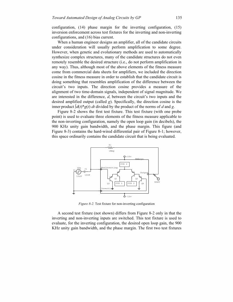
Figure 8-2 shows the first test fixture. This test fixture (with one probe point) is used to evaluate three elements of the fitness measure applicable to the non-inverting configuration, namely the open loop gain (in decibels), the 900 KHz unity gain bandwidth, and the phase margin. This figure (and Figure 8-3) contains the hard-wired differential pair of Figure 8-1; however, this space ordinarily contains the candidate circuit that is being evaluated.
VOUT
Inverting
CCS 2CCS 1
CCS 3
NonInverting
V
Embryo
Output
+15v
-15v
100F
C1
10uV
V11Hz
-+
Q2Q1
Q4Q3
R1
1Meg
Figure 8-2. Test fixture for non-inverting configuration
A second test fixture (not shown) differs from Figure 8-2 only in that the inverting and non-inverting inputs are switched. This test fixture is used to evaluate, for the inverting configuration, the desired open loop gain, the 900 KHz unity gain bandwidth, and the phase margin. The first two test fixtures

136 GENETIC PROGRAMMING THEORY AND PRACTICE II are used for inversion enforcement to ensure that specified values are achieved while the amplitude and phase of the output signals are inverted.
A third test fixture (not shown) measures the bias current. This test fixture differs from Figure 8-2 only in that there is no signal source, there is no capacitor, and there is a 1 mega-Ohm resistor between ground and the inverting input.
A fourth test fixture (not shown) measures the offset voltage (bias). This test fixture differs from Figure 8-2 only in that there is no signal source, there is no capacitor, and a wire replaces the 1 mega-Ohm feedback resistor.
VNORM-IDEAL
VNORM-EVOLVED
VREFERENCEMULT3
MULT2
MULT4
GAIN1 INTEG3
INTEG2SQRT2
VOUT
INTEG1
MULT1
MINUS1
VGAINRATIO
A
B
DIVV
DIVV2
VDIRECTIONCOSINEDIVV1
B
ADIVV
SQRT1
Inverting
NonInverting
VOFFSET
CCS 2CCS 1
CCS 3
V
V
V
V
V
V
V
Embryo
Output
+15v
-15v
Q3
1E3
1F
C2
SQRT
10k
R23HzV2
10uV
-+
SQRT
R1
100k
Q1 Q2
Q4
100F
C1
10uV
V15Hz
-+
Figure 8-3. Test fixture with four probe points.
The fifth test (Figure 8-3) fixture is more complex than the others. The fifth test has four probe points and is used to evaluate seven elements of the fitness measure. The four probe points are VOUT (output of the evolved circuit), VGAINRATIO, VDIRECTIONCOSINE, and VOFFSET. This test fixture is used to evaluate the initial 10dB amplification, the output voltage under different loads (two corners of the load envelope), direction cosine, the gain ratio, the offset voltage, the output swing, and the output swing direction cosine. This particular test fixture is noteworthy in that it illustrates the use of hard-wired non-modifiable electrical components to enable the test fixture to perform part of the fitness calculations (the remainder of the calculations being performed in software). Specifically, the ideal norm, VNORM-IDEAL, is computed by passing the incoming signals V1 and V2 through subtractor block MINUS1 (to obtain the differential input of V1 and V2) and feeding the difference into gain block GAIN1 (which amplifies the signal according to the DC power value connected to it). Then, the signal GAIN1 is squared by feeding it to both inputs of multiplier block MULT2. The output of MULT2 is fed into integrator block INTEG2. The output of INTEG2 is then fed into square root block SQRT2 to produce VNORM-IDEAL. Similarly, the norm for the evolved circuit, VNORM-EVOLVED, is

Toward Automated Design of Analog Circuits by GP 137 obtained using multiplier block MULT1, integrator block INTEG1, and square root block SQRT1. VREFERENCE is ascertained by multiplying GAIN1 by VOUT (at MULT3) and integrating at INTEG3. The direction cosine, VDIRECTIONCOSINE, is obtained by dividing VREFERENCE by the product of the two norms (VNORM-EVOLVED and VNORM-IDEAL). Finally, VGAINRATIO is obtained by dividing VNORM-EVOLVED by VNORM-IDEAL (at division block DIVV2).
Our focus here is on the engineering techniques for conducting an automated search in the absence of detailed information about the complex interrelationships among the various elements of the fitness measure.
First of all, even a little information can go a long way toward constructing a serviceable fitness measure that efficiently navigates a complex search space. For example, one thing that is almost always known is the identity of the preeminent element of the fitness measure (gain, in the case of an amplifier). The subspace of circuits that can actually amplify an incoming signal is an infinitesimal fraction of the space of possible circuits.
By heavily rewarding circuits that deliver even as little as 10 dB of gain (which can be obtained from even a single poorly deployed transistor), the search can be directed away from degenerate circuits (e.g., single wires) that deliver no gain at all, but which achieve alluringly good sub-optimal scores for secondary elements of the fitness measure (e.g., bias and distortion).
Second, after identifying the preeminent element of the fitness measure, we can weight the remaining elements equally in the sense that they will each make a certain common detrimental numerical contribution to fitness in a worst case that is likely to be occur. For this problem, an arbitrary common value of 30,000 was chosen.
Table 8-3. Elements of the fitness measure organized into four groups.
Preeminent element Amplifier-like behavior Single required
value Signal matching
• 10dB initial gain • Phase margin (inverting) • Phase margin (non-inverting) • Unity gain bandwidth (inverting) • Unity gain bandwidth (non-inverting) • Phase and amplitude inversion
• Desired Decibel gain (inverting) • Desired decibel gain (non-inverting) • Output swing • Offset voltage • Bias current • Variable load performance • Supply current
• Direction cosine • Gain ratio • Output swing direction cosine

138 GENETIC PROGRAMMING THEORY AND PRACTICE II
Third, the 16 elements of the fitness measure can be organized into four groups, as shown in Table 8-3. Column 1 of the table pertains to the just-discussed preeminent element of the fitness measure (gain). Column 2 contains elements of the fitness measure that ensure amplifier-like behavior. The unity gain bandwidth gives the upper limit to the useful passband of the amplifier. The phase margin is a mark of the amplifier’s stability. Checking the phase and amplitude inversion ensures that we are dealing with a differential amplifier. When satisfied simultaneously, these elements of the fitness measure indicate the evolved circuit is a stable differential amplifier operating in a passband of interest. These characteristics would be a starting assumption of a practicing engineer when evaluating circuits for the remaining criteria. Usually, pace-setting best-of-generation individuals achieve satisfactory scores for these elements of the fitness measure during early generations of a run. Column 3 contains elements of the fitness measure that entail satisfactorily matching a single value. Column 4 contains elements of the fitness measure that entail satisfactorily matching a signal (curve) in the time-domain. The sum of the absolute errors is ideally 0; however, a satisfactory amplifier can have some residual error.
Fourth, because we do not have detailed information about the interrelationships among the various elements of the fitness measure, it is desirable to minimize the number of occasions where we need to quantify the tradeoff between disparate elements of the fitness measure. This can be accomplished by identifying all elements of the fitness measure for which there is no practical advantage to improvement once some minimal level of performance has been achieved. As soon as a satisfactory level is achieved for these elements, the detrimental contribution to fitness from that particular element is set to zero and no subsequent reward is given for additional improvement. In other words, these elements of the fitness measure are treated as constraints in that they make a non-zero detrimental numerical contribution to fitness only if the candidate circuit is considered to be in the infeasible region, but make no detrimental contribution once the constraint is satisfied. The elements in columns 2 and 3 of Table 8-3 can all be treated as constraints in this way, in the hope and expectation that their contribution to fitness will quickly become zero. If, and to the extent that, these contributions quickly become zero, we avoid having to quantify the tradeoff between these elements of the fitness measure.
There are four recognizable phases in typical runs of this problem: (1) initial topology search, (2) formation of a core topology, (3) component solution, and (4) refinement.
Phase 1 occurs in generations 0 and 1 and establishes initial topologies that deliver at least 10 dB of gain (column 1 of Table 8-3) and that exhibit amplifier-like behavior (the elements shown in column 2 of Table 8-3).

Toward Automated Design of Analog Circuits by GP 139
Figure 8-4 shows, for selected generations, the fitness of the best-of-generation individual for one run. The height of each bar represents the individual’s fitness and the divisions within each bar show the contribution of eight selected elements of the fitness measure that illustrate the progress of the run. The eight selected elements are the differential gain direction cosine, gain ratio, offset voltage, supply current, output swing, output swing direction cosine, variable load resistance, and bias current. In Figure 8-5, the logarithm of these same eight fitness element are stacked on top of each other. The composition of each stack shows the progressive reduction (i.e., improvement) in the values of the eight elements.
0
100000
200000
0 1 4 8 10 16 17 19 22 27 29 35 44 52 60 63 74 82 92 104 113 120Generation
Fitness
Bias CurrentVariable Load ResistanceOutput SwingOutput Swing Direction CosineSupply CurrentOffset VoltageGain RatioDirection Cosine
Figure 8-4. Progressive change among eight selected elements of the fitness measure.
Phase 2 of the run searches for a core topology. In generation 17, a core topology emerges that links the differential pair (Q1–Q4), a transistor (Q5), a resistor (R1), the positive power supply (V+), and the output. This topology persists for the remainder of the run. During this phase, the magnitude of each of the remaining elements of the fitness measure in Figure 8-5 is substantially reduced. Although none of the elements are driven to 0, this phase establishes a baseline value for the next phase.
In phase 3, the required values of the elements shown in the third column of Table 8-3 are driven to 0. As progress is made in reducing the various elements of the fitness measure, the core topology that first appeared in generation 17 is augmented by additional electrical components.
During phase 3, there are 3 sub-phases in which the run concentrates on one, two, or three elements of the six elements of the fitness measure shown in the second column of Table 8-3. For example, in the second sub-phase of phase 3 (between generations 18 and 29), a current mirror is added to the circuit to help drive the penalties associated with the gain ratio and output swing to 0. In the second sub-phase of phase 3 (between generation 30 and

140 GENETIC PROGRAMMING THEORY AND PRACTICE II 73), the run concentrates on offset voltage, bias current, and variable load performance (i.e., the corners of the load envelope). The variable load performance becomes satisfied with the addition of current source I1.
In the third sub-phase of phase 3 (generations 74 to 113), the offset voltage and bias currents become satisfied. In generation 104 the bias current is pulled below the target value with the introduction of current source I4.
0 1 4 8 10 16 17 19 22 27 29 35 44 52 60 63 74 82 92 104 113 120Generation
Sum [ log(Fitness Element) ]
Bias CurrentVariable Load ResistanceOutput SwingOutput Swing Direction CosineSupply CurrentOffset VoltageGain RatioDirection Cosine
Figure 8-5. Logarithmic scale showing progressive change among eight selected elements of
the fitness measure.
Generation 113 sees the offset voltage satisfied by substitution of a previously placed transistor with a current mirror consisting of Q6 and Q7, completing what would be the core of the solution circuit.
In phase 4, the remaining residual error of the fitness measure elements in the third column of Table 8-3 are pushed toward their ideal values. The best-of-run individual from generation 120 (Figure 8-6) satisfies all constraints and all other minimum specifications, except that the supply current is 30 milliamperes. Although the supply current is not in compliance, its detrimental contribution to fitness is less than the sum of all of the errors.
A second run (using an arguably more realistic worst-case scaling for supply current), followed a similar four-phase chronology. The best-of-run individual satisfied all constraints and specifications except that the bias current was 112 nano-amperes (instead of less than 80 nano-amperes).
7. CONCLUSIONS
The chapter discussed progress toward the synthesis of industrial-strength automated design of analog circuits by means of genetic programming by describing five ways for using general domain knowledge

Toward Automated Design of Analog Circuits by GP 141 about circuits, three ways for employing problem-specific knowledge, four ways of improving on previously published genetic programming techniques, and four ways of grappling with the multi-objective fitness measure needed to synthesize an amplifier circuit.
V+
V-
Output
NonInverting Inverting
R1
521
3.27Meg
R3
Q9
R2 1.77Meg
Q16
1G
1G
1k
1G
1G
Q22
1G
Q8
Q7
I4 951uA
-+Q2
49.7uA
I2
- +Q10
D2Q6
D1
I3
60.9uA
- +
13.7pAI5
-+
I1
1.37mA
- +
Q5
Q21
Q12
Q13
Q3
Q14
Q17 Q15
Q18
Q20
Q19
D3
Q4Q1
Figure 8-6. Best-of-run circuit from generation 120.
Acknowledgements
We are indebted to Trent McConaghy (formerly of Analog Design Automation Inc. of Ottawa, now a part of Synopsys) for suggesting this amplifier problem and useful discussions about it.
References
Aaserud, O. and Nielsen, I. Ring. (1995). Trends in current analog design: A panel debate. Analog Integrated Circuits and Signal-Processing. 7(1)5–9.
Balkir, Sina, Dundar, Gunhan, and Ogrenci, A. Selcuk. (2003). Analog VLSI Design Automation. Boca Raton, FL: CRC Press.
Banzhaf, Wolfgang, Nordin, Peter, Keller, Robert E., and Francone, Frank D. (1998). Genetic Programming– An Introduction. San Francisco, CA: Morgan Kaufmann.
Graeb, Helmut E., Zizala, S., Eckmueller, J., and Antreich, K. 2001. The sizing rules method for analog circuit design. Proceedings of the IEEE/ACM International Conference on Computer Aided Design. Piscataway, NJ: IEEE Press. Pages 343-349.
142 GENETIC PROGRAMMING THEORY AND PRACTICE II Holland, John H. (1975). Adaptation in Natural and Artificial Systems: An Introductory
Analysis with Applications to Biology, Control, and Artificial Intelligence. Ann Arbor, MI: University of Michigan Press. Second edition. Cambridge, MA: The MIT Press 1992.
Keane, Martin A., Koza, John R., and Streeter, Matthew J. (2002). Improved General-Purpose Controllers. U.S. patent application filed July 12, 2002.
Koza, John R. (1990). Genetic Programming: A Paradigm for Genetically Breeding Populations of Computer Programs to Solve Problems. Stanford University Computer Science Dept. technical report STAN-CS-90-1314. June 1990.
Koza, John R. (1992). Genetic Programming: On the Programming of Computers by Means of Natural Selection. Cambridge, MA: MIT Press.
Koza, John R. (1994). Genetic Programming II: Automatic Discovery of Reusable Programs. Cambridge, MA: MIT Press.
Koza, John R., Bennett III, Forrest H, Andre, David, and Keane, Martin A. (1996). Automated design of both the topology and sizing of analog electrical circuits using genetic programming. In Gero, John S. and Sudweeks, Fay (editors). Artificial Intelligence in Design '96. Dordrecht: Kluwer Academic Publishers. Pages 151–170.
Koza, John R., Bennett III, Forrest H, Andre, David, and Keane, Martin A. (1999). Genetic Programming III: Darwinian Invention and Problem Solving. San Francisco, CA: Morgan Kaufmann.
Koza, John R., Keane, Martin A., Streeter, Matthew J., Mydlowec, William, Yu, Jessen, and Lanza, Guido.(2003). Genetic Programming IV: Routine Human-Competitive Machine Intelligence. Kluwer Academic Publishers.
Koza, John R., Mydlowec, William, Lanza, Guido, Yu, Jessen, and Keane, Martin A. (2001). Reverse engineering of metabolic pathways from observed data using genetic programming. In Altman, Russ B. Dunker, A. Keith, Hunter, Lawrence, Lauderdale, Kevin, and Klein, Teri (editors). Pacific Symposium on Biocomputing 2001. Singapore: World Scientific. Pages 434–445.
Koza, John R., and Rice, James P. (1991). Genetic generation of both the weights and architecture for a neural network. In Proc. of International Joint Conference on Neural Networks, Seattle, July 1991. Los Alamitos, CA: IEEE Press. Volume II. Pages 397–404.
Koza, John R., Streeter, Matthew J., and Keane, Martin A. (2003). Automated synthesis by means of genetic programming of complex structures incorporating reuse, parameterized reuse, hierarchies, and development. In Genetic Programming: Theory and Practice Riolo, R. and Worzel W. (eds.). Boston, MA: Kluwer Academic Publishers. Pp. 221–237.
Langdon, William B. and Poli, Riccardo. (2002). Foundations of Genetic Programming. Springer-Verlag.
Lanza, Guido, Mydlowec, William, and Koza, John R. (2000). Automatic creation of a genetic network for the lac operon from observed data by means of genetic programming. Poster paper accepted for First International Conference on Systems Biology in Tokyo on November 14–16, 2000.
Lohn, Jason, Hornby, Gregory, and Linden, Derek. (2003). Evolutionary antenna design for a NASA spacecraft. Chapter 18 of this volume.
Quarles, Thomas, Newton, A. R., Pederson, D. O., and Sangiovanni-Vincentelli, A. 1994. SPICE 3 Version 3F5 User’s Manual. Department of Electrical Engineering and Computer Science, University of California. Berkeley, CA. March 1994.
Spector, Lee. 2004. Automatic Quantum Computer Programming: A Genetic Programming Approach. Boston: Kluwer Academic Publishers.
Sripramong, Thanwa and Toumazou, Christofer. (2002). The invention of CMOS amplifiers using genetic programming and current-flow analysis. IEEE Trans. on Computer-Aided Design of Integrated Circuits and Systems. 21(11). November 2002. Pages 1237–1252.