Total Internal Reflection...
24
Ann. Rev. Biophys. Bioen 9. 1984.13 : 24748 Copyrioht © 1984 by Annual Reviews Inc. All riohts reserved TOTAL INTERNAL REFLECTION FLUORESCENCE Daniel Axelrod BiophysicsResearchDivision and Department of Physics, University of Michigan, Ann Arbor, Michigan 48109 Thomas P. Bur~thardt Cardiovascular Research Institute, University of California, San Francisco, California 94143 Nancy L. Thompson Department of Chemistry, Stanford University, Stanford, California 94305 INTRODUCTION Total internal reflection fluorescence (TIRF) is an optical effect particularly well-suitedto the studyof molecular and cellular phenomena at liquid/solid interfaces. Such interfaces are central to a wide range of biochemical and biophysical processes: binding to and triggering of cells by hormones, neurotransmitters, and antigens; blood coagulation at foreign surfaces; electron transport in the mitochondrial membrane; adherence and mo- bility of bacteria, algae, andculturedanimal cells to surfaces; andpossible enhancement of reaction rates with cell surface receptors upon nonspecific adsorption andsurface diffusionof an agonist. Liquid/solid interfaces also have important medical and industrial applications: e.g. detection of serum antibodies by surface immobilized antigens; and the manufacture of biochemical ~aroducts by surface-immobilized enzymes. Total internal reflection spectroscopy for optical absorption studies (called attenuated total reflection or ATR) wasdeveloped somewhat earlier than the fluorescence applications and has been widely used in surface chemistry studies (17). Thebasic book in this area is lnternal Reflection 247 0084-6589/84/0615-0247502.00 Annual Reviews www.annualreviews.org/aronline Annu. Rev. Biophys. Bioeng. 1984.13:247-268. Downloaded from arjournals.annualreviews.org by University of Illinois - Urbana Champaign on 02/02/09. For personal use only.
Transcript of Total Internal Reflection...
Ann. Rev. Biophys. Bioen9. 1984.13 : 24748Copyrioht © 1984 by Annual Reviews Inc. All riohts reserved
TOTAL INTERNALREFLECTION FLUORESCENCE
Daniel Axelrod
Biophysics Research Division and Department of Physics,University of Michigan, Ann Arbor, Michigan 48109
Thomas P. Bur~thardt
Cardiovascular Research Institute, University of California,San Francisco, California 94143
Nancy L. Thompson
Department of Chemistry, Stanford University, Stanford, California 94305
INTRODUCTION
Total internal reflection fluorescence (TIRF) is an optical effect particularlywell-suited to the study of molecular and cellular phenomena at liquid/solidinterfaces. Such interfaces are central to a wide range of biochemical andbiophysical processes: binding to and triggering of cells by hormones,neurotransmitters, and antigens; blood coagulation at foreign surfaces;electron transport in the mitochondrial membrane; adherence and mo-bility of bacteria, algae, and cultured animal cells to surfaces; and possibleenhancement of reaction rates with cell surface receptors upon nonspecificadsorption and surface diffusion of an agonist. Liquid/solid interfaces alsohave important medical and industrial applications : e.g. detection of serumantibodies by surface immobilized antigens; and the manufacture ofbiochemical ~aroducts by surface-immobilized enzymes.
Total internal reflection spectroscopy for optical absorption studies(called attenuated total reflection or ATR) was developed somewhat earlierthan the fluorescence applications and has been widely used in surfacechemistry studies (17). The basic book in this area is lnternal Reflection
2470084-6589/84/0615-0247502.00
Annual Reviewswww.annualreviews.org/aronline
Ann
u. R
ev. B
ioph
ys. B
ioen
g. 1
984.
13:2
47-2
68. D
ownl
oade
d fr
om a
rjou
rnal
s.an
nual
revi
ews.
org
by U
nive
rsity
of
Illin
ois
- U
rban
a C
ham
paig
n on
02/
02/0
9. F
or p
erso
nal u
se o
nly.

248 AXELROD, BURGHARDT & THOMPSON
Spectroscopy by Harrick (18). Total iffternal reflection optics have also beencombined with Raman spectroscopy (24, 32), X-ray fluorescence (2),infrared absorption spectroscopy (16), and light scattering (3, 33).
As a technique for selective surface illumination, total internal reflectionfluorescence was first introduced by Hirschfeld (21) for solid/liquidinterfaces, Tweet et al (39) for liquid/air interfaces, and Carniglia & Mandel(13) for high refractive index liquid/solid interfaces. TIRF has beencombined with a variety of other conventional fluorescence techniques(polarization, Ffrster energy transfer, microscopy, spectral analysis, photo-bleaching recovery, and correlation spectroscopy) for a variety of purposes(detection of molecular adsorption; measurement of adsorption equilib-rium constants, kinetic rates, surface diffusion, adsorbate conformation;and observation of cell/substrate contact regions). This r~view is organizedaccording to those purposes. We begin with a summary’of the relevantoptical theory.
THEORY
Evanescent IntensityWhen a light beam propagating through a transparent medium of highindex of refraction (e.g. a solid glass prism) encounters an interface with medium of a lower index of refraction (e.g. an aqueous solution), undergoes total internal reflection for incidence angles (measured from thenormal to the interface) greater than the "critical angle." The critical angle0c, is given by
0c = sin- 1 (n2/nt), 1.
where n2 and nl are the refractive indices of the liquid and the solid,respectively. Although the incident light beam totally internally reflects atthe interface, an electromagnetic field called the "evanescent wave"penetrates a small distance into the liquid medium and propagates parallelto the surface in the plane of incidence. The evanescent wave is capable ofexciting fluorescent molecules that might be present near the interface. Thiseffect has been regarded as experimental proof of the existence of theevanescent wave (44).
The evanescent electric field intensity I(z) decays exponentially withperpendicular distance z from the interface:
I(z) = Ioe-~/a,
where20 2
d = ~ In1 sin2 0- n~2] - 1/2 2.
Annual Reviewswww.annualreviews.org/aronline
Ann
u. R
ev. B
ioph
ys. B
ioen
g. 1
984.
13:2
47-2
68. D
ownl
oade
d fr
om a
rjou
rnal
s.an
nual
revi
ews.
org
by U
nive
rsity
of
Illin
ois
- U
rban
a C
ham
paig
n on
02/
02/0
9. F
or p
erso
nal u
se o
nly.

TOTAL REFLECTION FLUORESCENCE 249
for angles of incidence 0 > 0c and light wavelength in vacuum 20. Depth d isindependent of the polarization of the incident light and decreases withincreasing 0. Except for 0 -~ 0c (where d ~ ~), d is on the order of 20 smaller.
The intensity at z = 0, Io, depends on both the incidence angle 0 and theincident beam polarization. Io is proportional to the square of theamplitude of the evanescent electric field E at z = 0.1 (These expressions aregiven in the next subsection.) For incident electric field intensities J" ’± withpolarizations parallel and perpendicular, respectively, to the plane ofincidence, the evanescent intensities I~,± are
I~ = ,~11 4 cos2 0(2 sin20--n2)n~ cos~ 0 + sin~ O- n~ 3.
and
4 cos2 0Io ~ = d±’ - 4.l_n 2 ,
where
n = n2/nl < 1. 5.
Figure 1 illustrates Iio I’± as functions of 0. Note several features: (a) theevanescent intensity I~ ’± is not weak and can be several times stronger thanthe incident intensity for angles of incidence within a few degrees ofthe critical angle; (b) the intensities of the two polarizations are different,with I~ somewhat more intense for all 0; (c) Iio I’± both approach zero as0~90°.
Evanescent Fields
The phase behavior of the E field is quite remarkable (7). The fieldcomponents are listed below, with incident electric field amplitudes A II ,±and phase factors relative to those of the incident E and H fields’ phase atz = 0. (The coordinate system is chosen such that the x-z plane is the planeof incidence.)
[(n2~_ e-~s2cOs 0~_~ ~-n7(sin2 0--n2)1/2 l _,,, +~.:,Ex
-~--~-~/z l Aile,, / , 6.
[ 2cosol~:,, = Lii-- ~-)-rn j A±e-"% 7.1 The evanescent intensity that excites fluorescence is given by IEI2 (12, 13). Generally,
the energy flux of an electromagnetic field is given by the real part of the Poynting vector,S = (c/4n)E x H, where H is the magnetic field. For a transverse field, 181 is proportional toIEI2. Note that for an evanescent wave, ISl is not proportional to IEI2.
Annual Reviewswww.annualreviews.org/aronline
Ann
u. R
ev. B
ioph
ys. B
ioen
g. 1
984.
13:2
47-2
68. D
ownl
oade
d fr
om a
rjou
rnal
s.an
nual
revi
ews.
org
by U
nive
rsity
of
Illin
ois
- U
rban
a C
ham
paig
n on
02/
02/0
9. F
or p
erso
nal u
se o
nly.

250 AXELROD~ BURGHARDT & THOMPSON
[~n* 2 cos 0 sin 0-I _~
where
F (sin2 O-- n2)U2 7~11 -= tan-~ k ~-~-c--~-~ J 9.
and
6z -- tan -~ L = -c-~s -0 J" 10.
Note that the evanescent electric field is transverse to the propagation. direction (+x) only for the _k polarization. The It polarization E field
5,0 --
I~,l vs. 0
4.54.0 - ,\~ n = 1’33A,50 =0.88-/
3.5- \ \Io" "
>" 3.0 \\~~
2.0 -
’"-~.0
0.5-
0t;00c 65 70 75 80 85 90INCIDENCE ANGLE O (deg.)
Figure 1 Intensiti¢s I~ ’z vs incid¢nc: an#¢ e, for n = 0.887, corresponding to a critical angl¢ofO~ = 62.46°. Intensity is expressed as the ratio ofevanes~nt intensity at ~ = 0 to the incidentintensity for each polarization.
Annual Reviewswww.annualreviews.org/aronline
Ann
u. R
ev. B
ioph
ys. B
ioen
g. 1
984.
13:2
47-2
68. D
ownl
oade
d fr
om a
rjou
rnal
s.an
nual
revi
ews.
org
by U
nive
rsity
of
Illin
ois
- U
rban
a C
ham
paig
n on
02/
02/0
9. F
or p
erso
nal u
se o
nly.

TOTAL REFLECTION FLUORESCENCE 251
"cartwheels" along the surface with a spatial period of 2o/(nl sin 0) asshown schematically in Figure 2.
For absorbers with magnetic dipole transitions, the evanescent magneticfield H is relevant. Assuming equal magnetic permeabilities at both sides ofthe interface, the components of the evanescent field H at z = 0 are
t_ I’2 cos 0~_1 ~nin2)-iTT(sin2 O--n2)1/2-] -i(t5 -~)Hx
Hr =-- (n* COS2 0+sin20--n2) ~/2’ A)le-i(atl-’~/2)’ 12.
H~ = (1 -n2) ~/2 A±e-i~" 13.
The angular dependence of the phase factors ~± and ~ II gives rise to ameasurable longitudinal shift of a finite-sized incident beam, known as theGoos-I-Ianehen shift (29). Viewed physically, some of the energy of a finite-width beam crosses the interface into the lower refractive index material,skims along the surface for a Goos-Hanchen shift distance ranging from afraction of a wavelength (at 0 -- 90°) to infinite (at 0 = 0c), and then reentersthe higher refractive index material.
In many TIRF experiments, an incident laser beam of Gaussian intensityprofile passes through a converging lens, enters the side of a prism, and thenfocuses at a totally reflecting surface. The nature of the evanescent
EVANESCENT~" "~ field . +Z
:::::::::::::::::::::::i:i:i:.’i:i:i:i::: :i¥i:i:i. ’i:i:i:i:i:i:i:i:i:i:i:i.’:i:i:i:i:i:i:i:i:i:i:i:: ::::::::::::::::::::::::: ::
Figure 2 Electric field vectors of incident and evanescent light for the II incident polarization,showing the phase lag 6 II and the "cartwheel" or elliptical polarization of the evanescent field inthe plane of propagation. Both the incident and evanescent vectors refer to the z = 0 position ;they are schematically displaced a distance e (~0) below and above the interface along theirconstant phase lines for pictorial clarity only.
Annual Reviewswww.annualreviews.org/aronline
Ann
u. R
ev. B
ioph
ys. B
ioen
g. 1
984.
13:2
47-2
68. D
ownl
oade
d fr
om a
rjou
rnal
s.an
nual
revi
ews.
org
by U
nive
rsity
of
Illin
ois
- U
rban
a C
ham
paig
n on
02/
02/0
9. F
or p
erso
nal u
se o
nly.

252 AXELROD, BURGHARDT & THOMPSON
illumination produced by such a focused finite beam geometry has beeninvestigated in general (12). For typical experimental conditions, theevanescent illumination is of an elliptical Gaussian profile and thepolarization and penetration depth are approximately equal to those of aplane wave.
The angular distribution of evanescent wave-excited fluorescence whenviewed through the prism is anisotropic. A complete discussion appears inLee et al (26).
Intermediate Layers
Thus far, the theoretical discussion has assumed that the medium in whichthe evanescent wave propagates contains no light absorbers, light scat-terers, layers of unmatched refractive index, or electrical conductors. Theeffect of such intermediate layers is clearly relevant to TIRF.
The presence of absorbers perturbs the evenescent wave and therebydisturbs the linearity between actual surface concentration of absorber andobserved fluorescence. (This effect is roughly analogous to the "inner filter"effect in conventional fluorimetry in which a high concentration offluorophore attenuates the incident light.) Burghardt & Axelrod (10) havecalculated the magnitude of this nonlinear effect as a function of surfaceconcentration of absorbing material of arbitrary thickness. The result ofthis calculation shows that typical TIRF experiments are well within thelinear range in which observed fluorescence and surface concentration areproportional. Harrick (18) displays results of an analogous calculation the effect of absorbers on the intensity of the reflected laser beam.
Aside from the effect of absorbers, the presence of an intermediate layer ofa homogeneous dielectric material of unmatched refractive index depositedon the totally reflecting surface can clearly affect the evanescent waveintensity and characteristic decay distance (31). Total internal reflectionmay even occur at the interface between the intermediate layer and the lowrefractive index medium. Regardless of their refractive indices, intermediatelayers cannot thwart total internal reflection at some interface in the systemif it would have occurred without the intermediate layers.
If a metallic conductor is deposited onto the interface, entirely newphenomena can be observed (15, 42). Rather than emitting fluorescenceisotropically, an evanescent wave-excited dye molecule adsorbed to theintermediate metal layer will tend to transfer its energy to surface plasmonsin the adjacent metal. If the metal film is sufficiently thin, the emission canthen be observed as a hollow cone of light propagating back through theprism. If a semiconductor thin film is deposited on the interface, one mightobserve charge transfer between an excited dye molecule and the conduc-tion band of the semiconductor (30).
Annual Reviewswww.annualreviews.org/aronline
Ann
u. R
ev. B
ioph
ys. B
ioen
g. 1
984.
13:2
47-2
68. D
ownl
oade
d fr
om a
rjou
rnal
s.an
nual
revi
ews.
org
by U
nive
rsity
of
Illin
ois
- U
rban
a C
ham
paig
n on
02/
02/0
9. F
or p
erso
nal u
se o
nly.

TOTAL REFLECTION FLUORESCENCE 253
The scattering of evanescent light by an intermediate layer has beentreated theoretically (14). Evanescent light scattering is the basis of the darkfield microscope introduced by Ambrose (3) for examining culturedbiological cell-substrate contacts and also is the basis of a study ofphotoreceptor membrane attached to optical fibers (33). Whether scatter-ing significantly increases the effective depth of light penetration into thelow optical density medium has been tested in some of the experimentalsystems discussed in following sections.
In the next three sections, we review experimental results with TIRFoptics.
ADSORPTION AT EQUILIBRIUM:DETECTION AND CALIBRATION
In an early published application of TIRF, Tweet et al (39) measured theemission spectrum and quenching behavior of chlorophyll a monolayers atan aqueous/air interface (see Figure 3a). TIRF provided a means detecting the weak fluorescence from a very dilute monolayer with a highdegree of exclusion of direct and scattered mercury arc excitation light.
A short note by Hirschfeld (21) introduced TIRF at a solid/liquidinterface. A special cell (Figure 3b) designed to fit a commercial absorptionspectrophotometer and providing for multiple total reflections of excitationlight in a fused silica microscope slide was used to study the fluorescence offluorescein in the 1-1000 ppm bulk concentration range. The goal here wasto study bulk-dissolved dye in the vicinity of an interface rather thanadsorbed dye. Hirschfeld lists several advantages of TIRF over conven-tional illumination for this purpose. (a) The small depth of penetration the evanescent wave combined with observation of fluorescence emittedback into the prism could allow studies of turbid or highly adsorbingsolutions. (b) The intensity/concentration relationship was linear at up two orders of magnitude higher concentration for TIRF than for conven-tional illumination. (c) Effects of adsorption or the proximity of glass uponthe fluorescence properties could be detected by changing the excitationincidence angle and thereby the penetration depth. (d) The possibility multiple total reflections in the same prism allows the excitation to interactwith the sample many times, thereby increasing sensitivity. (e) Manyfluorescent materials (dyes, labeled proteins, etc) strongly adsorb onto solidsurface from very dilute solutions, often unavoidably depleting the bulkconcentration of the fluorophore and dramatically increasing the effectivelocal concentration of the fluorophore in the proximity of the surface.Selective surface excitation by TIRF thereby leads to an effective enhance-ment of sensitivity to extremely low concentrations of fluorophore.
Annual Reviewswww.annualreviews.org/aronline
Ann
u. R
ev. B
ioph
ys. B
ioen
g. 1
984.
13:2
47-2
68. D
ownl
oade
d fr
om a
rjou
rnal
s.an
nual
revi
ews.
org
by U
nive
rsity
of
Illin
ois
- U
rban
a C
ham
paig
n on
02/
02/0
9. F
or p
erso
nal u
se o
nly.

254 AXELROD, BURGHARDT & THOMPSON
The sensitivity of TIRF to adsorbed films containing a fluorophore canbe upgraded further, as described by Harrick & Loeb (19, 20). With a prismin which multiple total internal reflection of excitation light takes place andalso in which much of the fluorescence emission is also trapped by totalinternal reflection, a large fluorophore-coated surface area can be observedwith a large effective solid angle of light collection (Figure 3c). In oneapplication of this sort of optics, a film of dansyl-labeled bovine serumalbumin (BSA) was adsorbed onto a fused silica prism and dried in air. Notethat the fluorescence here is not excited by the evanescent wave as
~M
PM
Thin Film
p’~" ~:.. ~! ~!i~ ~:.~ [E ~:!:!:!:~.~:.;i~.:.’!:!:!:~::~:::::~
Air or H20
PM
..... ~,F’M M croscopeIll’ !1 t ’l,l~’Objective
~~ (e)
I ~]Excitation- - ~ Mono-
(~ ~chromoto
o (~)
F~gure 3 Optical designs for some TIRF experiments as described in the text. These aresimplified drawings showing the general excitation geometries with most of the lenses in theexcitation and emission pathways not shown. The following abbreviations are used: (3, glassmicroscope slide; PM, photomultiplier (always assumed to be preceded by a colored opticalfilter to block scattered excitation light); P, prism (usually optical glass or fused silica); S,solution containing fluorophore (usually a fluorescence-labeled serum protein); M, mirror; incident light beam.
Annual Reviewswww.annualreviews.org/aronline
Ann
u. R
ev. B
ioph
ys. B
ioen
g. 1
984.
13:2
47-2
68. D
ownl
oade
d fr
om a
rjou
rnal
s.an
nual
revi
ews.
org
by U
nive
rsity
of
Illin
ois
- U
rban
a C
ham
paig
n on
02/
02/0
9. F
or p
erso
nal u
se o
nly.

TOTAL REFLECTION FLUORESCENCE 255
previously described, since total internal reflection occurs at the proteinfilm/air interface instead of the silica prism/film interface. Rather, TIRserves to confine both the excitation and emission light on the film-coatedprism, allowing entrance and exit of light only at one hemicylindricallyshaped end.
Kronick & Little (25) have employed TIRF with an immunologicallyspecific antigen-coated surface to assay for specific fluorescent-labeledantibodies in solution. The antigen complimentary to the antibody isconjugated to egg albumin and then is physically adsorbed onto a fusedsilica slide. The excitation light, from a helium cadmium laser, is introducedinto the slide via an optical coupling with a trapezoidal shaped prism(Figure 3d). As fluorescent antibodies attach to the surface-immobilizedantigens, the evanescent wave-excited fluorescence increases. The chieflimit to the specific sensitivity of this assay is the nonspecific binding ofantibodies to the egg albumin coated surface. This problem is less severewith strongly binding antigen-antibody combinations and specially treatedsurfaces that reduce nonspecific protein binding. With a silica slide coatedby the antigen morphine, a concentration of 2 × 10⁻⁷ M of dissolvedfluorescent labeled antimorphine could be detected Specifically in theirTIRF system. The system remains to be tested for success in assayingantibodies in blood serum.
A very elegant TIRF method and apparatus for assaying for viruses inhuman blood serum (called a "virometer") has been described by Hirschfeldand co-workers (22, 23) for use on the stage of an upright microscope(Figure 3e). A serum sample, mechanically filtered to eliminate particulateslarger than virus particles, is treated with a nucleic-acid binding fluoro-phore and then observed by TIRF. As fluorescent-labeled constituents inthe serum enter and leave the evanescent wave in the bulk, they cause visiblefluorescence fluctuations. Because of their large size, the virions diffuse byBrownian motion more slowly than other fluorescent constituents andthereby cause slower fluorescence fluctuations. By autocorrelating thefluctuations, this slower component can be resolved. From the relativeamplitude of this slow component, the absolute concentration of virionscan be calculated. Mixtures of two fluorescent nucleic acid stains of widelydifferent emission spectra could allow distinction between different types ofvirions. TIRF illumination, as opposed to conventional microscope epi-illumination, served mainly to (a) define a very small distance--thepenetration depth d--through which virions can traverse in a short time,and (b) avoid background fluorescence from out-of-focus planes in thesolution. The principles of the virometer are similar to some of those laterapplied in total internal reflection/fluorescence correlation spectroscopy(TIR/FCS) (38) for other purposes to be described later in the next section.
Annual Reviewswww.annualreviews.org/aronline
Ann
u. R
ev. B
ioph
ys. B
ioen
g. 1
984.
13:2
47-2
68. D
ownl
oade
d fr
om a
rjou
rnal
s.an
nual
revi
ews.
org
by U
nive
rsity
of
Illin
ois
- U
rban
a C
ham
paig
n on
02/
02/0
9. F
or p
erso
nal u
se o
nly.
256 AXELROD, BURGHARDT & THOMPSON
In TIRF experiments in which an adsorbed fluorophore is in reversiblechemical equilibrium with bulk-dissolved fluorophore, it is desirable todetermine what proportion of the observed fluorescence arises fromactually adsorbed fluorophore versus bulk fluorophore merely closeenough to the surface to be excited by the evanescent wave or scatteredincident light. Given either (a) an independent calibration of adsorbedsurface concentration (10), (b) an independent measurement of total number of illuminated fluorescent molecules (36), or (c) an dependent measurement of fluorescence from a nonadsorbant in a TIRFapparatus (27, 32a), the proportion of adsorbed vs bulk molecules can calculated. Alternatively, the fraction of illuminated fluorophore that isadsorbed can be determined from the abscissa intercept of a plot ofevanescent field depth (which can be varied with incidence angle; seeEquation 2) vs measured fluorescence (corrected for the variation evanescent intensity with incidence angle; see Figure 1). Another method ofdetermining the adsorbed fraction of illuminated fluorophore is tointerpolate the degree of polarization anisotropy of the sample’s fluores-cence (with adsorbed and bulk fluorophore in equilibrium) between that purely adsorbed and purely solubilized fluorophore. (This method assumesslower rotational motion of adsorbed fluorophore compared to solubilizedfluorophore.) Finally, the ratio r of fluorescent intensity to the intensity ofthe water so!vent’s Raman scattering peak can be compared between asurface under evanescent illumination and a bulk solution under conven-tional illumination. The relative values of ratio r are directly related to thefraction of illuminated fluorophore that is adsorbed. A large increase inratio r (typically observed upon serum’protein adsorption) demonstratesthe dominance of surface adsorbed to bulk-dissolved fluorophore underTIRF illumination.
CHEMICAL KINETICS AND SURFACE DIFFUSION
It is often of interest to know how rapidly a solute adsorbs to a surface, howlong it stays there before it desorbs, and whether it diffuses along the surfacewhile adsorbed. Many of the studies in this area involve adsorption of
blood serum proteins to nonbiol.q.~ical surfaces, partly because of therelevance to blood coagulation in medical prostheses.
The most direct approach to chemical kinetics in a TIRF system is a"concentration-jump": rapidly increasing bu!k concentration from zero toa final value to measure adsorption rates, or the reverse to measuredes0rption rates. Employing this approach, Watkins & Robertson (41)measured the time course of uptake (as well as equilibrium adsorptionisotherms) for fluorescein-labeled albumin, ),-globulin, and fibrinogen onto
Annual Reviewswww.annualreviews.org/aronline
Ann
u. R
ev. B
ioph
ys. B
ioen
g. 1
984.
13:2
47-2
68. D
ownl
oade
d fr
om a
rjou
rnal
s.an
nual
revi
ews.
org
by U
nive
rsity
of
Illin
ois
- U
rban
a C
ham
paig
n on
02/
02/0
9. F
or p
erso
nal u
se o
nly.

TOTAL REFLECTION FLUORESCENCE 257
Siliclad or silicone rubber-coated surfaces from static solution, and for y-globulin onto silicone rubber from flowing solutions (Figure 3f). Onequalitatively significant finding was a reversibly bound layer of y-globulinconstituting as much as 4070 of the total surface bound protein.
Lok et al (27, 28) continued these type of studies with bovine albumin andfibrinogen adsorbing onto silicone rubber from flowing solutions. They findthat the initial rate of adsorption for both proteins is diffusion limited (i.e.every solute molecule hitting an available site on surface sticks to it), andalso that fibrinogen uptake does not plateau after several hours and mayadsorb in multilayers. A particularly careful discussion of contributionsfrom bulk-dissolved fluorophore and scattered incident light arising inartificial polymer coatings is presented in Lok et al (27).
The possibility exists that extrinsic fluorophores on serum proteins mightaffect the rates and amounts of physical adsorption. To avoid thispossibility, Van Wagenen et al (40) studied the intrinsic tryptophanfluorescence of bovine serum albumin and ~-globulins adsorbed to fusedsilica following concentration jumps in a flushable cell. The general opticalarrangement for TIRF was similar to that of Watkins & Robertson (41)(Figure 3f), but with the variations that the light source was an Hg-Xe arcinstead of an argon laser and that both the excitation and emissionwavelengths could be scanned by monochromators in order to obtainspectra. Both proteins studied exhibited a very rapid initial phase ofadsorption from low bulk concentrations; y-globulin also showed aprolonged slow uptake component continuing for at least 40 min after itsintroduction. Albumin adsorption continued to occur at concentrationsexceeding those required for monolayer coverage, leading to the authors’inference of multilayers on the surface. No evidence is available as yet as towhether extrinsic probes affect the adsorption behavior seen with probe-free serum proteins.
Beissinger & Leonard (6) employed a multiple internal reflection prismadaptable to a commercial spectrofluorimeter to measure the concen-tration jump adsorption kinetics of fluorescein-labeled human ~-globulinto fused silica under flow conditions (Figure 3g). Again, both reversible andrelatively irreversible binding was detected, with the reversible componentincreasing linearly with bulk concentration. Adsorption rates were found tobe proportional to solution concentration.
Surface desorption rates and surface diffusion coefficients can beobserved without perturbing the chemical equilibrium (as occurs in concentration jump) by combining TIR with either fluorescence photo-bleaching recovery (TIR/FPR) or fluorescence correlation spectroscopy(TIR/FCS) (38). In TIR/FPR, adsorbed molecules are irreversibly photo-bleached by a flash of laser beam focused at a total internal reflection
Annual Reviewswww.annualreviews.org/aronline
Ann
u. R
ev. B
ioph
ys. B
ioen
g. 1
984.
13:2
47-2
68. D
ownl
oade
d fr
om a
rjou
rnal
s.an
nual
revi
ews.
org
by U
nive
rsity
of
Illin
ois
- U
rban
a C
ham
paig
n on
02/
02/0
9. F
or p
erso
nal u
se o
nly.
258 AXELROD, BURGHARDT & THOMPSON
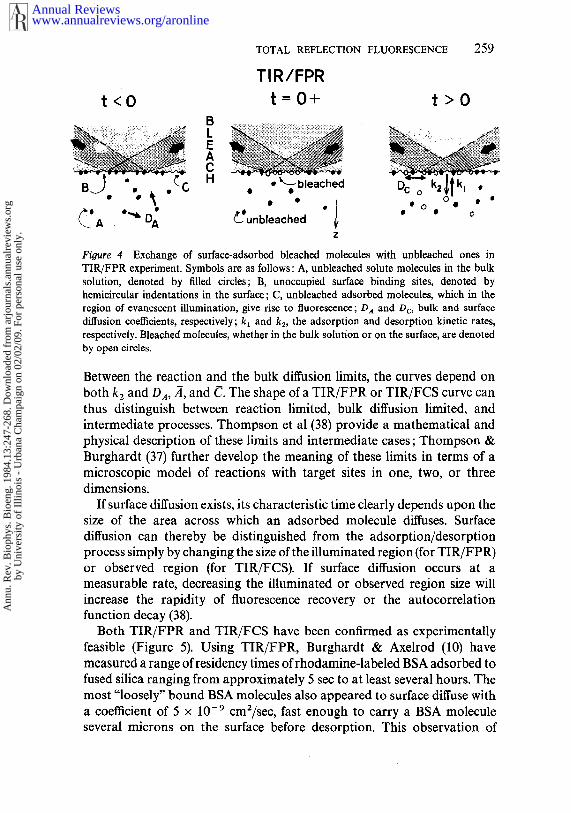
surface; subsequent fluorescence recovery vs time is monitored by anattentuated evanescent intensity as bleached molecules exchanged withunbleached ones from the solution or from surrounding nonilluminatedregions of the surface (Figure 4). In TIR/FCS, the evanescent intensity maintained at a constant and fairly dim level throughout, and spontaneousfluorescence fluctuations due to individual molecules entering and leaving awell-defined portion of the evanescent field are electronically autocor-related. In general, the shape of the theoretical TIR/FPR and TIR/FCScurves depends in a complex manner upon the bulk and surface diffusioncoefficients, the size of the illuminated or observed region, and the adsorp-tion and desorption kinetic rates. However, under appropriate experi-mental conditions, the rate constants and surface diffusion coefficientscan be readily obtained.
When the surface residency time of a reversibly bound adsorbant is muchlonger than the time necessary to enter or leave the vicinity of the observedsurface area, the process is in the "reaction limit." Mathematically, this limitis described by
(~/~)2/~ ~> ~4.k2 Da
Surface residency time >> Bulk diffusion time
where
1 (for TIR/FPR), fl -- fraction of surface binding sites that are unoccupied
at equilibrium (for TIR/FCS),
.~ = equilibrium concentration of bulk solute,
(~ = equilibrium concentration of surface adsorbed solute,
D,t = diffusion coefficient of solute in the bulk.
In the reaction limit for a large illuminated or observed area, thefluorescence recovery (for TIR/FPR) and the autocorrelation function (forTIR/FCS) depend only on k2 and the shape is exponential. Thus, in thereaction limit the desorption rate k2 can be obtained easily. Increasing thebulk concentration .~ or reducing the size of the observation area tends todrive the process toward the reaction limit.
If the opposite relationship to that of Equation 14 holds, for a largeilluminated or observed area, the process is in the "bulk diffusion limit," inwhich TIR/FPR and TIR/FCS curves depend only on D~ and theequilibrium concentrations. Physically, this limit occurs when the surfacebehaves as a nearly perfect sink with respect to the adsorbing molecules.
Annual Reviewswww.annualreviews.org/aronline
Ann
u. R
ev. B
ioph
ys. B
ioen
g. 1
984.
13:2
47-2
68. D
ownl
oade
d fr
om a
rjou
rnal
s.an
nual
revi
ews.
org
by U
nive
rsity
of
Illin
ois
- U
rban
a C
ham
paig
n on
02/
02/0
9. F
or p
erso
nal u
se o
nly.
t<O
TOTAL REFLECTION FLUORESCENCE 259
Fioure 4 Exchange of surface-adsorbed bleached molecules with unbleached ones inTIR/FPR experiment. Symbols are as follows: A, unbleached solute molecules in the bulksolution, denoted by filled circles; B, unoccupied surface binding sites, denoted byhemicircular indentations in the surface; C, unbleached adsorbed molecules, which in theregion of evanescent illumination, give rise to fluorescence; DA and Dc, bulk and surfacediffusion coefficients, respectively; kl and k2, the adsorption and desorption kinetic rates,respectively. Bleached molecules, whether in the bulk solution or on the surface, are denotedby open circles.
Between the reaction and the bulk diffusion limits, the curves depend onboth k2 and Da, ,~, and C. The shape ofa TIR/FPR or TIR/FCS curve canthus distinguish between reaction limited, bulk diffusion limited, andintermediate processes. Thompson et al (38) provide a mathematical andphysical description of these limits and intermediate cases; Thompson &Burghardt (37) further develop the meaning of these limits in terms of microscopic model of reactions with target sites in one, two, or threedimensions.
If surface diffusion exists, its characteristic time clearly depends upon thesize of the area across which an adsorbed molecule diffuses. Surfacediffusion can thereby be distinguished from the adsorption/desorptionprocess simply by changing the size of the illuminated region (for TIR/FPR)or observed region (for TIR/FCS). If surface diffusion occurs at measurable rate, decreasing the illuminated or observed region size willincrease the rapidity of fluorescence recovery or the autocorrelationfunction decay (38).
Both TIR/FPR and TIR/FCS have been confirmed as experimentallyfeasible (Figure 5). Using TIR/FPR, Burghardt & Axelrod (10) measured a range of residency times of rhodamine-labeled BSA adsorbed tofused silica ranging from approximately 5 see to at least several hours. Themost "loosely" bound BSA molecules also appeared to surface diffuse witha coefficient of 5 x 10 9 cmZ/sec, fast enough to carry a BSA moleculeseveral microns on the surface before desorption. This observation of
Annual Reviewswww.annualreviews.org/aronline
Ann
u. R
ev. B
ioph
ys. B
ioen
g. 1
984.
13:2
47-2
68. D
ownl
oade
d fr
om a
rjou
rnal
s.an
nual
revi
ews.
org
by U
nive
rsity
of
Illin
ois
- U
rban
a C
ham
paig
n on
02/
02/0
9. F
or p
erso
nal u
se o
nly.

260 AXELROD, BURGHARDT & THOMPSON
surface diffusion of a biological molecule may be significant in view of thehypothesis of Adam & Delbruck (1) that nonspecific adsorption anddiffusion on cell surfaces might enhance agonist/receptor reaction rates.
Using TIR/FCS, Thompson & Axelrod (36) have measured the non-specific adsorption/desorption kinetics of rhodamine-labeled immuno-globulin and insulin on serum albumin coated fused silica. Rapidly revers-ible adsorption could be visualized under TIR as twinkling speckles offluorescence as molecules enter and leave the evanescent wave region.Upon on-line autocorrelation of these fluorescence fluctuations, a range ofdesorption times was noted, with the shortest time less than 5 ms, limited bythe rate of bulk diffusion. Antibody molecules appeared to bind specificallyto antigen-coated fused silica, but this was accompanied by a large amountof reversible nonspecific binding. Such nonspecific binding is difficult toavoid and perhaps occurs on cell surfaces where it may be biochemicallyfunctional via the Adam & Delbruck (1) mechanism mentioned above. suitable systems where nonspecific binding is low, TIR/FCS and TIR/FPRshould prove useful for measuring specific solute-surface kinetic rates. In
FOCUSING ~/LENS .........
’*""’, CUBE / / /~ ...............,,, .......... /, / ....
SL,O ......... E S,ONIN~, I ~ ?~; ~I, ~ ---’-OUT
~ OBJECTIVE
Figure 5 Experimental apparatus for TIR/FPR, for use on the stage of an invertedmicroscope. Fluorescent solute molecules are indicated by x’s. The cubical prism and slide aremade of fused silica. The drilled hole in the bottom of the dish is covered with a glass coverslipand sealed in with encapsulating resin. The apparatus for TIR/FCS is qualitatively similar,except that the inflow and outflow tubes are omitted and the spacing between the slide and thebottom coverslip is reduced to only 0.06 mm with a thin Teflon spacer to enable use of highaperture, short working distance oil immersion objectives.
Annual Reviewswww.annualreviews.org/aronline
Ann
u. R
ev. B
ioph
ys. B
ioen
g. 1
984.
13:2
47-2
68. D
ownl
oade
d fr
om a
rjou
rnal
s.an
nual
revi
ews.
org
by U
nive
rsity
of
Illin
ois
- U
rban
a C
ham
paig
n on
02/
02/0
9. F
or p
erso
nal u
se o
nly.

TOTAL REFLECTION FLUORESCENCE 261
principle, TIR/FCS can even measure specific solute/surface kinetic rates atequilibrium of nonfluorescent molecules by competing them with fluor-escent analogs (35). In any case, TIR/FCS and TIR/FPR can be dis-tinguished from the TIR concentration jump method by their ability tomeasure very rapid rates without necessitating macroscopic perturbationof the equilibrium.
MOLECULAR CONFORMATION OF ADSORBATES
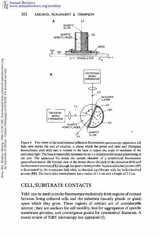
The conformational and dynamical properties of adsorbed proteins can bestudied by combining TIRF with conventional fluorescence spectroscopictechniques such as singlet-singlet (F6rster) energy transfer and fluorescencepolarization. For this purpose, a TIRF chamber easily fitted into acommercial spectrofluorimeter for spectra analysis has been designed (11)(Figure 6). Using this chamber, the authors observed a decrease in effectiveenergy transfer rate upon adsorption in BSA multiply-labeled with thefluorophore donor/acceptor pairs of dansyl/eosin or 4-chloro-7-nitro-2,1,3-benzoxadiazole (NBD)/rhodamine. Under certain assumptions, thisenergy transfer change can be interpreted as a conformational change ofBSA upon adsorption. The intrinsic tryptophan fluorescence of unlabeledBSA was also found to be less quenchable by iodide ion when adsorbed tofused silica than when dissolved in bulk (D. Axelrod, unpublishedobservation). This result indicates either a conformational change uponadsorption or reduced accessibility of iodide to tryptophan residuesbecause of the proximity of the surface.
Using the same TIRF spectrofluorimeter chamber to measure steadystate fluorescence polarization, Burghardt (8) has inferred a decreasedrotational diffusion coefficient of NBD, rhodamine, or eosin fluorophoresaround their single covalent bonds binding them to BSA upon adsorptionof the BSA to fused silical The restricted rotational motion of the probe canbe attributed to direct steric interference by the surface or to stericinterference arising from a conformational change in BSA. (The same paperalso contains a mathematical derivation of the expected fluorescencepolarization anisotropy decay of a rotationally diffusing fluorophore whileconnected to an anisotropically rotationally diffusing protein.)
Preliminary experiments have been performed using TIRF with time-resolved fluorescence lifetime and anisotropy decay measurements to detectthe fluorescence lifetimes and rotational motion of labeled protein at thesolid/liquid interface (T. P. Burghardt and P. M. Torgerson, unpublishedobservations). These particular experiments utilize the unique polarizationcharacteristics of the evanescent electric field to deduce the order ofarrangement of labeled proteins in a biological structure (9).
Annual Reviewswww.annualreviews.org/aronline
Ann
u. R
ev. B
ioph
ys. B
ioen
g. 1
984.
13:2
47-2
68. D
ownl
oade
d fr
om a
rjou
rnal
s.an
nual
revi
ews.
org
by U
nive
rsity
of
Illin
ois
- U
rban
a C
ham
paig
n on
02/
02/0
9. F
or p
erso
nal u
se o
nly.
262 AXELROD~ BURGHARDT & THOMPSON
A ,zQUARTZ ISLIDE ~
QUARTZ HSHEMICYLINDER-
X-Y TRANSLATOR ®X "Y
B EXCITATIONMONO-
CHROMATOR
~/EX GLYCERI N
~~S
EMISSION F]/,~ jL ~MONO- I~I.-~ -I------~
CHROMATOR I VQUARTZ
/EX SLIDE
Figure 6 Two views of the total internal reflection fluorescence spectroscopy apparatus. (A)Side view shows the axis of rotation, z, about which the prism and slide and Plexiglasshemicylinder shell (HS) unit is rotated in the base to adjust the angle of incidence of theexcitation light. The base is removably mounted on an x-y translator for lateral positioning ofthe unit. The apparatus fits inside the sample chamber of a commercial fluorescencespectrofluorometer. (B) Vertical view of the device shows the path of the excitation (EX) the fluorescent emission (FL) through the quartz hemicylinder. Surface-adsorbed protein (SP)is illmninated by the evanescent field while in chemical equilibrium with the bulk-dissolvedprotein (BP). The fused silica hemicylinder has a radius of 1.3 crn and a height of 2.5 cm.
CELL/SUBSTRATE CONTACTS
TIRF can be used to excite fluorescence exclusively from regions of contactbetween living cultured cells and the substrate (usually plastic or glass)upon which they grow. These regions of contact are of considerableinterest : they are anchors for cell motility, loci for aggregation of specificmembrane proteins, and convergence points for cytoskeletal filaments. Arecent review of TIRF microscopy has appeared (5).
Annual Reviewswww.annualreviews.org/aronline
Ann
u. R
ev. B
ioph
ys. B
ioen
g. 1
984.
13:2
47-2
68. D
ownl
oade
d fr
om a
rjou
rnal
s.an
nual
revi
ews.
org
by U
nive
rsity
of
Illin
ois
- U
rban
a C
ham
paig
n on
02/
02/0
9. F
or p
erso
nal u
se o
nly.

TOTAL REFLECTION FLUORESCENCE 263
Several experimental designs for TIRF microscopy are possible. Figure 7(from 4) shows a design appropriate for an inverted fluorescence micro-scope. Phase contrast transmitted illumination and epi-illumination (i.e.through the objective) are easily interchanged with TIRF without changingthe basic configuration (Figure 8). By varying the incidence angle of thetotally reflecting laser beam, and thus the depth of evanescent illumination,details of the topography of the cell surface near the substrate can berevealed (4, 5).
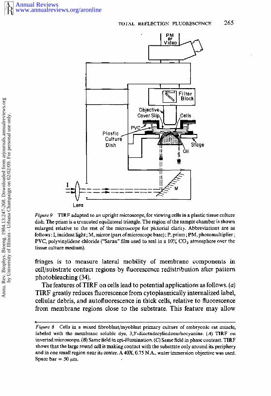
Another TIRF design (Figure 9) (D. Axelrod, unpublished), used in upright microscope, is particularly convenient for directly viewing cellsgrowing in disposable plastic tissue culture dishes and works quite welldespite the autofluorescence of tissue culture polystyrene plastic. (Corningbrand dishes have significantly less autofluorescence than Falcon, Lux, orNunc brands and are thereby more suitable.) Both this design and the oneshown in Figure 7 permit the cells to be moved laterally while retaining TIRillumination centered in the microscope’s field of view.
A third design (43) (for an inverted microscope) employs a triangularprism to guide a laser beam into a microscope slide where it undergoesmultiple internal reflections (Figure 10). The cells may reside on top of theslide (for any kind of cells) (A. Brian and N. L. Thompson, unpublished) underneath the slide (for tightly adhering cells). A novel feature is the use intersecting laser beams (split from the same laser) at the total internalreflection surface to create a parallel line interference fringe pattern. Thisinterference pattern can be seen on the fluorescing regions of cell/substratecontact, thereby confirming that the primary source of excitation is indeedthe evanescent wave rather than light randomly scattered from theevanescent wave by the cells. Another potential application of these TIRF
GLASSCUBE
LASERBEAM
COVERSLIP
C OVE.SL,, \\\
LENS ..."
STAG E
Figure 7 TIRF inverted microscope apparatus for viewing cells in culture. Cells are platedand grown on a standard glass coverslip, which is then inverted and placed in optical contactwith the cubical prism via a layer of immersion oil or glycerin.
Annual Reviewswww.annualreviews.org/aronline
Ann
u. R
ev. B
ioph
ys. B
ioen
g. 1
984.
13:2
47-2
68. D
ownl
oade
d fr
om a
rjou
rnal
s.an
nual
revi
ews.
org
by U
nive
rsity
of
Illin
ois
- U
rban
a C
ham
paig
n on
02/
02/0
9. F
or p
erso
nal u
se o
nly.

264 AXELROD, BURGHARDT & THOMPSON
Annual Reviewswww.annualreviews.org/aronline
Ann
u. R
ev. B
ioph
ys. B
ioen
g. 1
984.
13:2
47-2
68. D
ownl
oade
d fr
om a
rjou
rnal
s.an
nual
revi
ews.
org
by U
nive
rsity
of
Illin
ois
- U
rban
a C
ham
paig
n on
02/
02/0
9. F
or p
erso
nal u
se o
nly.
TOTAL REFLECTION FLUORESCENCE 265
Plastic ~-CultureDish
Lens
Obiec i eJ
~CoverSlip , Cells
-- I ~ :~Tage
II
Fi[ture 9 TIRF adapted to an upright microscope, for viewing cells in a plastic tissue culturedish. The prism is a truncated equilateral triangle. The region of the sample chamber is shownenlarged relative to the rest of the microscope for pictorial clarity. Abbreviations are asfollows : I, incident light ; M, mirror (part of microscope base); P, prism; PM, photomultiplier;PVC, polyvinylidene chloride ("Saran" film used to seal in a 10% CO2 atmosphere over thetissue culture medium).
fringes is to measure lateral mobility of membrane components incell/substrate contact regions by fluorescence redistribution after patternphotobleaching (34).
The features of TIRF on cells lead to potential applications as follows. (a)TIRF greatly reduces fluorescence from cytoplasmically internalized label,cellular debris, and autofluorescence in thick cells, relative to fluorescencefrom membrane regions close to the substrate. This feature may allow
(
Figure 8 Cells in a mixed fibroblast/myoblast primary culture of embryonic rat muscle,labeled with the membrane soluble dye, 3,3’-dioctadecylindocarbocyanine. (A) TIRF inverted microscope. (B) Same field in epi-illuminatian. (C) Same field in phase contrast. shows that the large round cell is making contact with the substrate only around its peripheryand in one small region near its center. A 40X, 0.75 N.A., water immersion objective was used.Space bar = 50
Annual Reviewswww.annualreviews.org/aronline
Ann
u. R
ev. B
ioph
ys. B
ioen
g. 1
984.
13:2
47-2
68. D
ownl
oade
d fr
om a
rjou
rnal
s.an
nual
revi
ews.
org
by U
nive
rsity
of
Illin
ois
- U
rban
a C
ham
paig
n on
02/
02/0
9. F
or p
erso
nal u
se o
nly.

266 AXELROD, BURGHARDT & THOMPSON
TOP VIEW
C’~
SIDE VIEWP2 P1
S P CS--’-"~ /~Oil
FigurelO TIRE microscopy combined with interference fringes. The top view shows the twolaser bearas intersecting at the region under observation. The side view shows the path of abeam as it enters a prism P1, totally reflects multiple times in a glass slide to which cells areadhered (in this case on the lower surface), and exits via prism P2. Abbreviations are as follows:BS, beam splitter; CS, coverslip; L, lens; M, mirror; S, slide; SP, spacer.
detection of lower concentrations of fluorescence-marked membranereceptors than would otherwise be possible. (b) Study of the submembranestructure of the cell-substrate contact in thick cells can be facilitated. Afluorescently labeled cytoskeletal structure in the contact region can bevisualized without interference from an out-of-focus background fromfluorescently labeled cytoskeletal structure farther from the substrate. (c) varying the incidence angle, the topography of the membrane facing thesubstrate can be mapped. (d) Reversibly bound fluorescent ligands membrane receptors might be visualized without exciting backgroundfluorescence from unbound ligand in the bulk solution. In thismanner,certain cell surface receptors might be studied without the necessity ofblocking them by irreversible antagonists.
EXPERIMENTAL SUGGESTIONS
In setting up a TIRF system, one may encounter a number of questionsabout design and materials. The following suggestions may be helpful.1. The prism used to couple the light into the system and the (usually
disposable) slide or coverslip in which the total reflection takes placeneed not be exactly matched in refractive index.
Annual Reviewswww.annualreviews.org/aronline
Ann
u. R
ev. B
ioph
ys. B
ioen
g. 1
984.
13:2
47-2
68. D
ownl
oade
d fr
om a
rjou
rnal
s.an
nual
revi
ews.
org
by U
nive
rsity
of
Illin
ois
- U
rban
a C
ham
paig
n on
02/
02/0
9. F
or p
erso
nal u
se o
nly.

TOTAL REFLECTION FLUORESCENCE 267
2. The prism and slide may be optically coupled with glycerin, cyclohex-anol, or microscope immersion oil, among other liquids. Immersion oilhas a higher index of refraction (thereby avoiding possible total internalreflection at the prism/glycerin interface for low incidence angles) buttends to be more autofluorescent (even the "extremely low" fluorescencetypes). This problem is usually not important to TIRF microscopy butcan be serious in large area applications.
3. The prism and slide can both be made of ordinary optical glass for manyapplications, unless shorter penetration depths arising from higherrefractive indices are desired. (More exotic high refractive indexmaterials such as sapphire, titanium dioxide, and strontium titanate canyield penetration depths as low as 20/20.) However, optical glass doesnot transmit light below about 310 nm and also has a dim autolumines-cence with a long (several hundred microsecond) decay time, which canbe a problem in some photobleaching experiments. The autolumines-cence of high quality fused silica (often called "quartz") is much lower.
4. The total internal reflection surface need not be polished to a higherdegree than a standard commercial microscope slide.
5. Either a laser or conventional arc light source will suffice for study ofmacroscopic areas. But in TIRF microscopy, a conventional light sourceis difficult to focus to a small enough region at high enough intensitywhile still retaining sufficient collimation to avoid partial light transmis-sion through the interface; a laser is more desirable here.
6. Illumination of surface-adsorbed proteins can lead to apparentphotochemically-induced cross-linking and also to photobleaching atthe higher range of intensities that might be used in TIRF studies.Apparent cross-linking, measured as a slow, continual, illumination-dependent increase in observed fluorescence, can be inhibited by 0.05 Mcysteamine, among other substances; photobleaching can be reducedsomewhat by deoxygenation or by 0.01 M sodium dithionite, amongother substances.
ACKNOWLEDGMENTS
We thank Peter M. Torgerson of the University of California, SanFrancisco, and Adrienne Brian of Stanford University for permittingcitation of some of their unpublished observations. This work wassupported by USPHS NIH grant # 14565 (to D.A.).
Literature Cited
1. Adam, G., Delbruck, M. 1968. InStructural Chemistry and MolecularBiology, ed. R. Alexander, D. Norman,pp. 198-215. San Francisco: Freeman
2. Aiginger, H., Wobrauschek, R. 1951. J.Radioanal. Chem. 61:281-93
3. Ambrose, E. J. 1961. Exp. Cell Res. Suppl.8 : 54-73
Annual Reviewswww.annualreviews.org/aronline
Ann
u. R
ev. B
ioph
ys. B
ioen
g. 1
984.
13:2
47-2
68. D
ownl
oade
d fr
om a
rjou
rnal
s.an
nual
revi
ews.
org
by U
nive
rsity
of
Illin
ois
- U
rban
a C
ham
paig
n on
02/
02/0
9. F
or p
erso
nal u
se o
nly.

268 AXELROD~ BURGHARDT & THOMPSON
4. Axelrod, D. 1981. J. Cell Biol. 89 : 141--455. Axelrod, D., Thompson, N. L., Burg-
hardt, T. P. 1983. J. Microsc. 129:Pt.I, pp. 19-28
6. Beissinger, R. L., Leonard, E. F. 1980.Am. Soc. Artif Internal Organs 3 : 160-75
7. Born, M., Wolf, E. 1975. Principles ofOptics. New York : Pergamon. 5th ed.
8. Burghardt, T. P. 1983. J. Chem. Phys.78 : 5913-19
9. Burghardt, T. P. 1983. Submitted forpublication
10. Burghardt, T. P., Axelrod, D. 1981. Bio-phys. J. 33:455-68
11. Burghardt, T. P., Axelrod, D. 1983.Biochemistry 22: 979-85
12. Burghardt, T. P., Thompson, N. L. 1984.Opt. Eng. In press
13. Carniglia, C. K., Mandel, L, Drexgage,K. H. 1972. J. Opt. Soc. Am. 62: 479-86
14. Chew, H., Wang, D., Kerker, M. 1979.Appl. Opt. 18:2679-87
15. Eagen, C. F., Weber, W. H., McCarthy,S. L., Terhune, R. W. 1980. Chem. Phys.Lett. 75 : 274-77
16. Fringeli, U. P., Gunthard, Hs. H. 1981. I~Membrane Spectroscopy, pp. 270-332.New York : Springer-Verlag
17. Haller, G. L., Rice, R. W., Wan, Z. C.1976. Catal. Rev. Sci. En9. 13 : 259-84
18. Harrick, N. J. 1967. Internal ReflectionSpectroscopy. New York : Wiley Intersc.
19. Harrick, N, J., Loeb, G. I. 1973. Anal.Chem. 45 : 687-91
20. Harrick, N. J., Loeb, G. I. 1982. Mod.Fluorescence Spectrosc. 1:211-25
21. Hirschfeld, T. 1965. Can, Spectrosc.10:128
22. Hirschfeld, T., Block, M. J. 1977. Opt.Eng. 16 : 406-7
23. Hirsehfeld, T., Block, M. J., Mueller, W.1977. J. Histochem. Cytochem. 25:719-23
24. Iwamoto, R., Miya, M., Onta, K. 1981. J.Chem. Phys. 74 : 4780-90
25. Kronick, M. N., Little, W. A. 1975. J.lmmunol. Methods 8 : 235-40
26. Lee, E.-H., Benner, R. E., Fen, J. B.,
Chang, R. K. 1979. Appl. Opt..18 : 862-6827. Lok, B. K., Cheng, Y.-L., Robertson, C.
R. 1983. J. Colloid Interface Sci. 91 : 87-102
28. Lok, B. K., Cheng, Y.-L., Robertson, C.R. 1983. J. Colloid Interface Sci. 91 : 104-16
29. McGuirk, M., Carniglia, C. K. 1977. J.Opt. Soc. Am. 67 : 103-7
30. Memming, R. 1974. Faraday Discuss.Chem. Soc. 58 : 261-70
31. Palik, E. D., Holm, R. T. 1978. Opt. Eng.17 : 512-24
32. Rabolt, J. F., Santo, R., Swalen, J. D.1979. Appl. Spectrosc. 33:549-51
32a. Rockhold, S. A., Quinn, R. D., VanWagenen, R. A., Andrade, J. D., Reiehert,M. 1983. J. Electroanal. Chem. 150:261-75
33. Selser, J. C., Rothschild, K. J., Swalen, J.D., Rondelez, F. 1982. Phys. Rev. Lett.48 : 1690-93
34. Smith, B. A., McConnell, H. M. 1978.Proc. Natl. Acad. Sci. USA 75 : 2759-63
35. Thompson, N. L. 1982. Biophys. J.38 : 327-29
36. Thompson, N. L., Axelrod, D. 1983.Biophys. J. 43 : 103-14
37. Thompson, N. L., Burghardt, T. P. 1983.Submitted for publication
38. Thompson, N. L., Burghardt, T. P.,Axelrod, D. 1981. Biophys. J. 33:435-54
39. Tweet, A. G., Gaines, G. L., Bellamy, W.D. 1964. J. Chem. Phys. 40: 2596-2600
40. Van Wagenen, R. A., Rockhold, $.,Andrade, J. D. 1982. In Biomaterials:lnterfacial Phenomena and Applications,Adv. Chem., ed. S. L. Cooper, N. A,Peppas, 199 : 351-70
41. Watkins, R. W., Robertson, C. R. 1977. J.Biomed. Mater. Res. 11:915-38
42. Weber, W. H., Eagen, C. F. 1979. Opt.Lett. 4: 236-38
43. Weis, R. M., Balakrishnan, K., Smith, B.A., McConnell, H. M. 1982. J. Biol.Chem. 257 : 6440-45
44. Wood, R. W. 1934. Physical Optics, pp.419-20. New York : Macmillan. 3rd ed.
Annual Reviewswww.annualreviews.org/aronline
Ann
u. R
ev. B
ioph
ys. B
ioen
g. 1
984.
13:2
47-2
68. D
ownl
oade
d fr
om a
rjou
rnal
s.an
nual
revi
ews.
org
by U
nive
rsity
of
Illin
ois
- U
rban
a C
ham
paig
n on
02/
02/0
9. F
or p
erso
nal u
se o
nly.

Ann
u. R
ev. B
ioph
ys. B
ioen
g. 1
984.
13:2
47-2
68. D
ownl
oade
d fr
om a
rjou
rnal
s.an
nual
revi
ews.
org
by U
nive
rsity
of
Illin
ois
- U
rban
a C
ham
paig
n on
02/
02/0
9. F
or p
erso
nal u
se o
nly.
Ann
u. R
ev. B
ioph
ys. B
ioen
g. 1
984.
13:2
47-2
68. D
ownl
oade
d fr
om a
rjou
rnal
s.an
nual
revi
ews.
org
by U
nive
rsity
of
Illin
ois
- U
rban
a C
ham
paig
n on
02/
02/0
9. F
or p
erso
nal u
se o
nly.