
Total heat recovery engine
14
1 Total Heat Recovery Engine - TOHRE Author: Eng. Liviu Grigorian Giurca 1. INTRODUCTION Internal combustion engine (ICE) was invented in 1876. Its typical four-stroke reciprocal piston configuration is still the primary engine format today. Modern spark ignition (SI) engine has 25% to 35% fuel conversion efficiency while modern compression ignition engine (CI) engine has 32% to 45%. This means that only 25% to 45% of the energy in the consumed fuel is converted into mechanical power, while the rest is lost through friction and heat. Due to millions of ICE currently in use worldwide, the improvement in ICE fuel conversion efficiency will have huge impacts on energy consumption, fuel economy, fuel reserve, dependency on foreign oil, and the environment. ICE causes air pollution by discharging emission gases. The emissions from millions of vehicles combine with sunshine and moisture to produce greenhouse effect. Although governments continue to pass through anti-pollution laws, automobile manufacturers are designing new vehicles with improved emissions, and oil companies are changing their formulations to burn more clearly, dangerous emissions from vehicles still remain an environment problem. In this context, one of the major content of ICE exhaust is carbon dioxide, which contributes to global warming. The increasing density of carbon dioxide traps the solar heat, causing the atmosphere temperatures to rise, leading to violent weather patterns and the melting of polar icecaps.
-
Upload
liviu-giurca -
Category
Automotive
-
view
339 -
download
0
Transcript of Total heat recovery engine

1
Total Heat Recovery Engine - TOHRE Author: Eng. Liviu Grigorian Giurca
1. INTRODUCTION
Internal combustion engine (ICE) was invented in 1876. Its typical four-stroke reciprocal piston configuration is still the primary engine format today. Modern spark ignition (SI) engine has 25% to 35% fuel conversion efficiency while modern compression ignition engine (CI) engine has 32% to 45%. This means that only 25% to 45% of the energy in the consumed fuel is converted into mechanical power, while the rest is lost through friction and heat. Due to millions of ICE currently in use worldwide, the improvement in ICE fuel conversion efficiency will have huge impacts on energy consumption, fuel economy, fuel reserve, dependency on foreign oil, and the environment.
ICE causes air pollution by discharging emission gases. The emissions from millions of vehicles combine with sunshine and moisture to produce greenhouse effect. Although governments continue to pass through anti-pollution laws, automobile manufacturers are designing new vehicles with improved emissions, and oil companies are changing their formulations to burn more clearly, dangerous emissions from vehicles still remain an environment problem.
In this context, one of the major content of ICE exhaust is carbon dioxide, which contributes to global warming. The increasing density of carbon dioxide traps the solar heat, causing the atmosphere temperatures to rise, leading to violent weather patterns and the melting of polar icecaps.

2
The best way to reduce carbon dioxide emissions is to burn less fossil fuel by using engines with higher efficiency. Even when we enter the era of biofuels and/or alternative fuels, or hydrogen fuels finally, increasing fuel conversion efficiency and reducing fuel consumption is still a significant strategic solution, because the higher the fuel costs, the higher the engine efficiency is expected.
It is believed that much of benefit would come from fuel efficiency improvement. Therefore, a new kind of heat engine, with much higher fuel conversion efficiency, is desired that addresses the immediate and specific needs of reducing fossil fuel consumption, reducing greenhouse gas discharge and reducing combustion exhaust emissions.
2. STATE OF THE ART
Some very efficient engines were already experimented and produced. One of this engines was achieved by Dr. Marius Paul for DARPA beginning with 1993. The Paul concept was built as opposed piston engine, each piston acting two counter-rotating crankshafts. The engine employs an ultra-high compression ratio in a Diesel variant. Almost 20 years ago, this variant already obtained 52% Brake Mean Efficiency and a huge power density, without heat recovery (Fig. 1).
Fig. 1
The fundamental thermal efficiency benefits of this engine type along with its low emissions, small package size and weight, and low cost relative to current engines make it an attractive alternative for future commercial and passenger vehicles.
Another new concept which uses a high compression ratio was developed by Motiv Engines LLC (fig. 2).

3
Fig. 2
This company introduced the second-generation of its engine concept dubbed the MkII Clarke-Brayton Engine, which it intends to develop into a heavy-duty on-highway engine fueled by liquid natural gas (LNG). The prototype is fueled by diesel, a first step in proving the technology before developing a new LNG fuel system.
Motiv suggests that the MkII engine will be up to twice as efficient as a conventional automobile engine and up to 20% more efficient than modern diesel engines. It achieves this by splitting the processes of an engine into three separate optimized spaces—i.e., across three optimized cylinders—rather than performing all the operations in a single “compromised” space. This allows it to implement a fundamentally more efficient cycle, achieve an extremely high 56:1 compression ratio leading to 30 MPa peak pressure, and lose much less of its energy to heat than a conventional engine due to the very small bore of the combustion chamber (the middle set of cylinders).
Motiv suggests that its engine design can deliver brake thermal efficiency of 52%, and the same power as a conventional engine but at 1/4 the size, as well as lower noise levels and less vibration.
There are a lot of other new engines such as Achates Power, EcoMotors and Pinnacle Engines that are working on alternative architecture engines claiming higher efficiency, but they are all working off the same old LIMITED cycles. This makes their claims on significantly higher efficiency hard to believe because thermodynamically these engines are not different from ones that have been built millions of times before. Some of them base claims of higher “efficiency” in a car by shutting down some cylinders during highway use or combining them in hybrid systems.
4
The fuel cell technology based on hydrogen utilization was considered by many specialists as the future global technology. The main advantage is its superior efficiency (maximum 50-60%), compared with the conventional engine. Unfortunately this efficiency decreases very much (around 40%) at high ambient temperature. On the other hand fuel cell uses precious and rare materials as platinum, which increases the costs and the risks to be very quickly worn-out.
Therefore a internal combustion engine, with hydrogen, having efficiency over 60% in all ambient conditions, offering a low cost alternative, can be considered the new global technology of the future.
3. NEW TOTAL HEAT RECOVERY ENGINE -TOHRE 3.1. Theoretical base of TOHRE
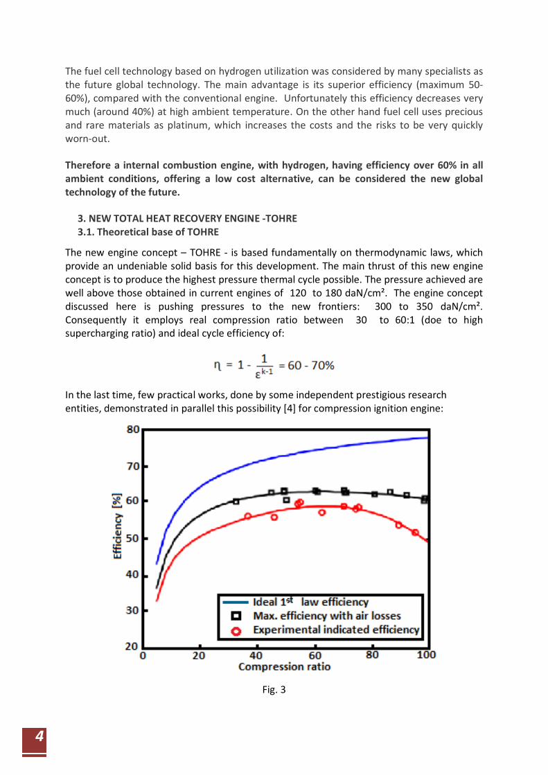
The new engine concept – TOHRE - is based fundamentally on thermodynamic laws, which provide an undeniable solid basis for this development. The main thrust of this new engine concept is to produce the highest pressure thermal cycle possible. The pressure achieved are well above those obtained in current engines of 120 to 180 daN/cm². The engine concept discussed here is pushing pressures to the new frontiers: 300 to 350 daN/cm². Consequently it employs real compression ratio between 30 to 60:1 (doe to high supercharging ratio) and ideal cycle efficiency of:
In the last time, few practical works, done by some independent prestigious research entities, demonstrated in parallel this possibility [4] for compression ignition engine:
Fig. 3
5
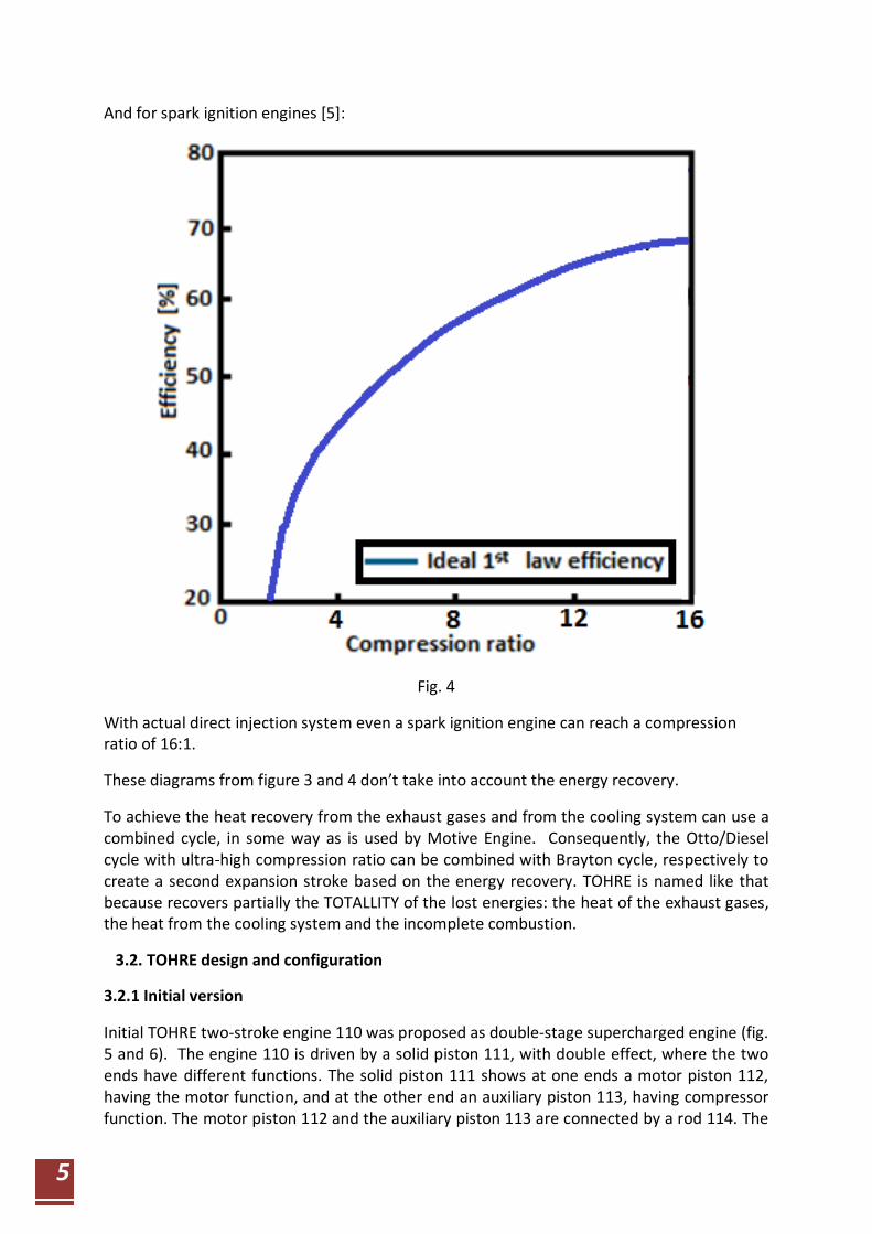
And for spark ignition engines [5]:
Fig. 4
With actual direct injection system even a spark ignition engine can reach a compression ratio of 16:1.
These diagrams from figure 3 and 4 don’t take into account the energy recovery.
To achieve the heat recovery from the exhaust gases and from the cooling system can use a combined cycle, in some way as is used by Motive Engine. Consequently, the Otto/Diesel cycle with ultra-high compression ratio can be combined with Brayton cycle, respectively to create a second expansion stroke based on the energy recovery. TOHRE is named like that because recovers partially the TOTALLITY of the lost energies: the heat of the exhaust gases, the heat from the cooling system and the incomplete combustion.
3.2. TOHRE design and configuration
3.2.1 Initial version
Initial TOHRE two-stroke engine 110 was proposed as double-stage supercharged engine (fig. 5 and 6). The engine 110 is driven by a solid piston 111, with double effect, where the two ends have different functions. The solid piston 111 shows at one ends a motor piston 112, having the motor function, and at the other end an auxiliary piston 113, having compressor function. The motor piston 112 and the auxiliary piston 113 are connected by a rod 114. The

6
motor piston 112 has an outer diameter substantially smaller than the outer diameter of the auxiliary piston 113. The motor piston 112 oscillates in a motor cylinder 115 and auxiliary piston 113 in an auxiliary cylinder 116. The motor cylinder 115 is included in a cylinder block 117 and is closed to the outside by a cylinder head 118. The auxiliary cylinder 116 is included in a cylinder block 119 which is closed on the outside by a cylinder head 120. The auxiliary cylinder 116 is employed as positive displacement compressor. The diameter of the auxiliary piston 113 is substantially bigger than the diameter of the motor piston 112. Therefore a high supercharging rate can be achieved. The first stage of the supercharger process is realized by a turbocharger 128, which uses the exhaust gases energy when is available. The exhaust duration and the supercharging rate are controlled by a rotating valve 125. The solid piston 111 transmits its oscillating motion to two connecting rods 130, using a balancer 131. Each connecting rod 130 acts a crankshaft 132. The two crankshafts 132 are synchronized by two gears 133. The lubrication system of this engine is similar with that used by a four-stroke engine.
Fig. 5
With a double-stage supercharging process and high geometrical compression ratio, a very big power density is obtained by this configuration.
7
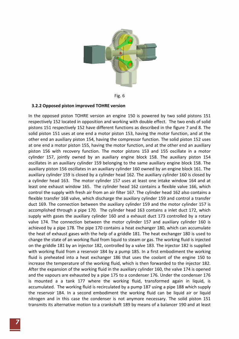
Fig. 6
3.2.2 Opposed piston improved TOHRE version
In the opposed piston TOHRE version an engine 150 is powered by two solid pistons 151 respectively 152 located in opposition and working with double effect. The two ends of solid pistons 151 respectively 152 have different functions as described in the figure 7 and 8. The solid piston 151 uses at one end a motor piston 153, having the motor function, and at the other end an auxiliary piston 154, having the compressor function. The solid piston 152 uses at one end a motor piston 155, having the motor function, and at the other end an auxiliary piston 156 with recovery function. The motor pistons 153 and 155 oscillate in a motor cylinder 157, jointly owned by an auxiliary engine block 158. The auxiliary piston 154 oscillates in an auxiliary cylinder 159 belonging to the same auxiliary engine block 158. The auxiliary piston 156 oscillates in an auxiliary cylinder 160 owned by an engine block 161. The auxiliary cylinder 159 is closed by a cylinder head 162. The auxiliary cylinder 160 is closed by a cylinder head 163. The motor cylinder 157 uses at least one intake window 164 and at least one exhaust window 165. The cylinder head 162 contains a flexible valve 166, which control the supply with fresh air from an air filter 167. The cylinder head 162 also contains a flexible transfer 168 valve, which discharge the auxiliary cylinder 159 and control a transfer duct 169. The connection between the auxiliary cylinder 159 and the motor cylinder 157 is accomplished through a pipe 170. The cylinder head 163 contains a inlet duct 172, which supply with gases the auxiliary cylinder 160 and a exhaust duct 173 controlled by a rotary valve 174. The connection between the motor cylinder 157 and auxiliary cylinder 160 is achieved by a pipe 178. The pipe 170 contains a heat exchanger 180, which can accumulate the heat of exhaust gases with the help of a griddle 181. The heat exchanger 180 is used to change the state of an working fluid from liquid to steam or gas. The working fluid is injected on the griddle 181 by an injector 182, controlled by a valve 183. The injector 182 is supplied with working fluid from a reservoir 184 by a pump 185. In a first embodiment the working fluid is preheated into a heat exchanger 186 that uses the coolant of the engine 150 to increase the temperature of the working fluid, which is then forwarded to the injector 182. After the expansion of the working fluid in the auxiliary cylinder 160, the valve 174 is opened and the vapours are exhausted by a pipe 175 to a condenser 176. Under the condenser 176 is mounted a a tank 177 where the working fluid, transformed again in liquid, is accumulated. The working fluid is recirculated by a pump 187 using a pipe 188 which supply the reservoir 184. In a second embodiment the working fluid can be liquid air or liquid nitrogen and in this case the condenser is not anymore necessary. The solid piston 151 transmits its alternative motion to a crankshaft 189 by means of a balancer 190 and at least

8
a connecting rod 191. The alternative motion is transmitted symmetrically by the solid piston 151 to a crankshaft 192 through the balancer 190 by means a connected rod 193. Similarly the solid piston 152 transmits its alternative motion to the crankshaft 189 by means of a balancer 194 and at least a connecting rod 195. The alternative motion is transmitted symmetrically by the solid piston 152 to the crankshaft 192 through the balancer 194 by means a connected rod 196. The rotation motion of the two crankshafts 189 and 192 is synchronized by two gears. The auxiliary cylinders 154 and 156 have the exterior diameters substantially larger than the motor piston 153 and 155.
Fig. 7
The engine 150 operates in the motor cylinder 157 as an usual opposed piston two-stroke engine having a single step supercharging system, carried out by the auxiliary cylinder 160 (figure 8). The burned gases generated in the motor cylinder 157 are discharged through the window 165 to a high temperature and are eventually depolluted in a device 179. Then exhaust gases transfer their heat in the heat exchanger 181 and continues on being discharged through the rotary valve 173, which during the exhaust process it is also open. After the window 165 is closed by the motor piston 155 and after the valve 173 locks the pipe 173, an amount of working fluid is injected on the hot griddle 181. The working fluid is transformed in steam or gases producing an explosive pressure in the pipe 178 and in the auxiliary cylinder 160, achieving a second expansion. The solid piston 152 is acted in opposed direction to produce an additional useful work. When the engine starts again the expansion into the motor cylinder 157, the valve 173 is open again and allows the evacuation of the steam from the pipe 175 to the condenser 176. The steam is reconverted into liquid state
9
and is collected as working fluid in the tank 177. The working fluid from the tank 177 is recirculated by the pump 187 and directed by the pipe 188 into the reservoir 184. Further the working fluid is forced by the pump 187 to flow through the heat exchanger 186 where is a preliminary heated, recovering some of the energy lost through cooling of the engine 150. Finally the working fluid is reinjected, in the right moment, on the hot griddle 181 where is again transformed in steam. This corresponds to the variant when the water is chosen as a working fluid.
In another variant the working fluid is liquid nitrogen or liquid air. In this embodiment, the condenser 176, the pump 187 and the pipe 188 are removed as liquid air or liquid nitrogen can no be longer recovered and are discharged into the atmosphere without being recycled.
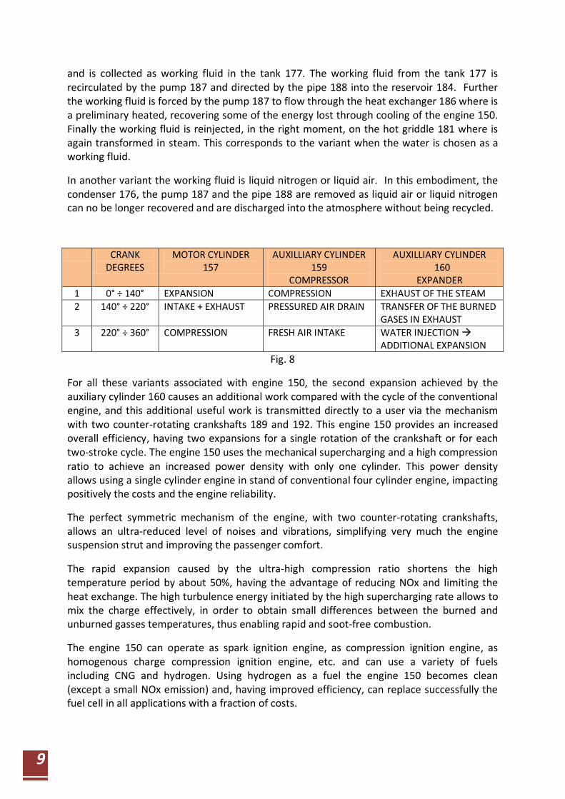
CRANK DEGREES
MOTOR CYLINDER 157
AUXILLIARY CYLINDER 159
COMPRESSOR
AUXILLIARY CYLINDER 160
EXPANDER 1 0° ÷ 140° EXPANSION COMPRESSION EXHAUST OF THE STEAM 2 140° ÷ 220° INTAKE + EXHAUST PRESSURED AIR DRAIN TRANSFER OF THE BURNED
GASES IN EXHAUST 3 220° ÷ 360° COMPRESSION FRESH AIR INTAKE WATER INJECTION
ADDITIONAL EXPANSION Fig. 8
For all these variants associated with engine 150, the second expansion achieved by the auxiliary cylinder 160 causes an additional work compared with the cycle of the conventional engine, and this additional useful work is transmitted directly to a user via the mechanism with two counter-rotating crankshafts 189 and 192. This engine 150 provides an increased overall efficiency, having two expansions for a single rotation of the crankshaft or for each two-stroke cycle. The engine 150 uses the mechanical supercharging and a high compression ratio to achieve an increased power density with only one cylinder. This power density allows using a single cylinder engine in stand of conventional four cylinder engine, impacting positively the costs and the engine reliability.
The perfect symmetric mechanism of the engine, with two counter-rotating crankshafts, allows an ultra-reduced level of noises and vibrations, simplifying very much the engine suspension strut and improving the passenger comfort.
The rapid expansion caused by the ultra-high compression ratio shortens the high temperature period by about 50%, having the advantage of reducing NOx and limiting the heat exchange. The high turbulence energy initiated by the high supercharging rate allows to mix the charge effectively, in order to obtain small differences between the burned and unburned gasses temperatures, thus enabling rapid and soot-free combustion.
The engine 150 can operate as spark ignition engine, as compression ignition engine, as homogenous charge compression ignition engine, etc. and can use a variety of fuels including CNG and hydrogen. Using hydrogen as a fuel the engine 150 becomes clean (except a small NOx emission) and, having improved efficiency, can replace successfully the fuel cell in all applications with a fraction of costs.

10
The engine design is exceptionally compact and robust, approximately half the size of a conventional reciprocating engine. It is ideally suited to a wide range of applications, ranging from 1kW to 100.000 kW, particularly designed for available space, weight, emissions, noise and vibration.
TOHRE is predicted to deliver a 40-50% efficiency gain compared to equivalent conventional engines with a cost reduction of about 30%. This efficiency gain would include a corresponding increase in fuel economy (BSFC ̴145 g/kWh) and a decrease in CO2 emissions. The engine is predicted to cost about 30% less due to its mechanical simplicity and compactness in a single piston version.
New engine cycle
The TOHRE geometrical compression ratio is between 30 to 50 and the expansion has long period, similar to the Atkinson cycle. The expansion is made in two different places as can be seen in the figures 9 and 10: one place is in the motor cylinder 157 and the other place is in the auxiliary cylinder 160. The green areas from both diagrams represent the load developed by TOHRE. The auxiliary cylinder works as a pneumatic two-stroke engine or expander.
The two expansion locations influence positively the engine efficiency. The rapid expansion caused by the ultra-high compression ratio shortens the high temperature period by about 50%, having the advantage of reducing NOx and limiting the heat exchange. The high turbulence energy initiated by the high supercharging rate allows to mix the charge effectively, in order to obtain small differences between the burned and unburned gasses temperatures, thus enabling rapid and soot-free combustion.
Fig. 9

11
Fig. 10
Hybrid THORE version
Using THORE as part of a hybrid electric powertrain or as part of an electric powertrain with range extender allows improving the powertrain arrangement and organizing architecture, making it compact and easy to be associated even with a conventional engine compartment. Being an auxiliary unit with high power density, THORE represent a cheap and simple solution.
Fig. 11

12
The THORE total weight can be very low and consequently the power unit can be easily carried by people and removed from the vehicle when its operation is not needed anymore. Therefore, this technology demonstrates and includes the possibility to be used on a portable range extender as is shown in the figure 11. A 30 kW power unit (using a starter-alternator) designed for a hybrid or for an electric vehicle with extended range can weight around 24 kg, the engine being fully balanced even with only one cylinder. On the other hand, when is not used on the vehicle, the portable range extender can be used as power back-up source for private and public buildings.
TOHRE used in Combined Heat and Power (CHP) plants for civil constructions
Combined Heat and Power (CHP) plants simultaneously generate electricity and heat at the point of use and can achieve fuel conversion efficiencies of up to 90%. Compare this to a traditional remote central power plant, where electricity is generated at 35%–55% efficiency and then transmitted over long distances, while the remaining 45%–65% of waste heat is left behind because it’s not easily transported. With growing environmental awareness and an increasing desire to reduce Carbon emissions, the efficiency difference is too large to be ignored. And of course, with rising fuel prices and an electric grid near maximal capacity, the economic benefits of good CHP applications can be substantial to both the investor and the local utility. Using THORE technology for CHP plants, the most energy quantity is transformed in electric energy and only a very limited part of it is used as heat. This makes the system more flexible and more efficient during summer, when too much heat for the house needs is not desirable. In addition, using THORE technology for CHP plants improves the durability and helps to achieve low maintenance costs.
Fig. 12

13
The benefits of THORE
The main advantage of this invention is the improved efficiency. In the table below (fig. 13) can be compared the estimated efficiency for different TOHRE solutions in the configuration as spark ignition (SI) and compression ignition (CI) engine.
No. THORE Variant SI CI
1 Two-stroke highly supercharged without heat recovery
40 % – 45 % 50 % – 55%
2 With Exhaust gas heat recovery 50 % – 55% 60 % – 65%
3 With Exhaust gas heat recovery + Cooling system heat recovery
60 % – 65% 70 % – 75%
The estimated TOHRE efficiency
Fig. 13
Modern late 21th century power plants, utilizing combined heat and power, could yield an overall efficiency as high as 55%, where different working fluids drive different power driving devices, obtaining a combined thermal efficiency. In the present case both, the produced energy and the recovered energies are collected as power directly by the engine shaft and all the process is developed in an ultra-compact and simple structure.
Also it can be observed that this engine largely surpasses the fuel cell efficiency (50 – 60 %) without to use precious materials, the fuel cell being considered until now the technology of the future.
The other engine advances that result from this work are: 1. Highest power density between 300 to 600 kW/l; 2. Reduced CO2 level; 3. Compensation of all rotating inertial forces; 4. Compensation of all 1st order oscillating forces (torque compensation); 5. No reaction due to torque impulses on the exterior of the engine are detectable; 6.Very low friction losses from the guidance of the piston by the connecting rods (the lateral guiding force of the piston is effected by the connected rods); 7. The use of large swept volumes with better thermodynamic efficiency; 8. Lowest fuel consumption between 95 and 145 g/kWh; 9. High durability mechanism; 10. Multi fuel capability including for CNG and hydrogen; 11. A dramatic reduction in cost of production and exploitation; 12. Universal use, i.e., military or commercial.
These evaluated values establish new frontiers that are now opening the possibility of achieving enormous increases in power density and efficiency to the future engines. This concept can be also the next step in developing a highly efficient compression-ignition 100% natural gas or hydrogen engine that can meet the up-coming greenhouse gas emissions regulations.
14
The TOHRE technology can be considered as “revolutionary” in terms of offered advantages and as “evolutionary” in terms of engine modifications (one crankshaft more).
A four-stroke version of this engine was also proposed by the authors.
Contact e-mail: [email protected]
Bibliography:
1. CALSTART - DEFENSE ADVANCED RESEARCH PROJECTS AGENCY COOPERATIVE AGREEMENT MDA972-95-2-0011, QUARTERLY REPORT, July 1 to September 30,1997
2. Advanced Components for Electric Vehicles and Hybrids Electric Vehicles, NIST Workshop, October 27-28, 1993, Gaithersburg, Maryland
3. http://www.neander-motors.com/ 4. Chris F. Edwards& others, Remarks on the Efficiency Potential of Chemical Engines,
Stanford University 5. http://web.mit.edu/16.unified/www/FALL/thermodynamics/notes/node26.html 6. http://www.hybrid-engine-hope.com


