TOTAL 210 SHEET Vendor DOC. NO. J160165DA002P4 … · Apply interpretation VIII-1-83-66 Yes Apply...
211
TOTAL 210 SHEET Vendor DOC. NO. J160165DA002P4 DOCUMENT TITLE: Design Calculations Axion Campana II Project P.O. NO: 4618956 Equipment Name: Process Gas Boiler ITEM NO: 013001Y01E07 AL E&C DOC. NO. 56032-4618956-000030 0 19.01.17 First issue Pirker Leitner Pirker REV. DATE DESCRIPTION CHECK APPROVED AUTH’D VENDOR NAME: Bertsch Energy GmbH & Co KG
Transcript of TOTAL 210 SHEET Vendor DOC. NO. J160165DA002P4 … · Apply interpretation VIII-1-83-66 Yes Apply...

TOTAL 210 SHEET
Vendor DOC. NO. J160165DA002P4
DOCUMENT TITLE: Design Calculations
Axion Campana II Project
P.O. NO: 4618956
Equipment Name: Process Gas Boiler
ITEM NO: 013001Y01E07
AL E&C DOC. NO. 56032-4618956-000030
0 19.01.17 First issue Pirker Leitner Pirker
REV. DATE DESCRIPTION CHECK APPROVED AUTH’D
VENDOR NAME: Bertsch Energy GmbH & Co KG
yongsheng.mao
打字机
√
yongsheng.mao
打字机
yongsheng.mao
打字机
yongsheng.mao
打字机
YSM
yongsheng.mao
打字机
2017/03/10
yongsheng.mao
打字机
yongsheng.mao
打字机

Content
Equipment: PGB 013001Y01E07
Page:
Saddles ................................................. 3 to 28
Shellside ................................................. 29 to 76
Tubeside ................................................. 77 to 159
Tubesheets ................................................. 160 to 210
ITEM NO: 013001Y01E07 1/210 AL E&C DOC. NO. 56032-4618956-000030

BERTSCHenergy G m b H & Co KG
Herrengasse 23, 6700 Bludenz, Austria
www.bertsch.at
COMPRESS Pressure Vessel Design Calculations
Item: Process Gas Boiler
Vessel No: 013001Y01E07
Customer: Air Liquide Global E&C Solutions SHANGHAI
Contract: 4618956-000SIN
Designer: Pirker
Date: 19.01.2017
ITEM NO: 013001Y01E07 2/210 AL E&C DOC. NO. 56032-4618956-000030

Table of ContentsSettings Summary.....................................................................................................................................................1/25
Weight Summary.......................................................................................................................................................3/25
Wind Code.................................................................................................................................................................4/25
Saddles......................................................................................................................................................................5/25
i
ITEM NO: 013001Y01E07 3/210 AL E&C DOC. NO. 56032-4618956-000030
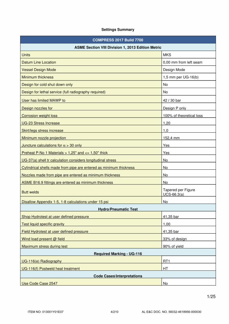
Settings Summary
COMPRESS 2017 Build 7700
ASME Section VIII Division 1, 2013 Edition Metric
Units MKS
Datum Line Location 0,00 mm from left seam
Vessel Design Mode Design Mode
Minimum thickness 1,5 mm per UG-16(b)
Design for cold shut down only No
Design for lethal service (full radiography required) No
User has limited MAWP to 42 / 30 bar
Design nozzles for Design P only
Corrosion weight loss 100% of theoretical loss
UG-23 Stress Increase 1,20
Skirt/legs stress increase 1,0
Minimum nozzle projection 152,4 mm
Juncture calculations for α > 30 only Yes
Preheat P-No 1 Materials > 1,25" and <= 1,50" thick Yes
UG-37(a) shell tr calculation considers longitudinal stress No
Cylindrical shells made from pipe are entered as minimum thickness No
Nozzles made from pipe are entered as minimum thickness No
ASME B16.9 fittings are entered as minimum thickness No
Butt weldsTapered per Figure
UCS-66.3(a)
Disallow Appendix 1-5, 1-8 calculations under 15 psi No
Hydro/Pneumatic Test
Shop Hydrotest at user defined pressure 41,35 bar
Test liquid specific gravity 1,00
Field Hydrotest at user defined pressure 41,35 bar
Wind load present @ field 33% of design
Maximum stress during test 90% of yield
Required Marking - UG-116
UG-116(e) Radiography RT1
UG-116(f) Postweld heat treatment HT
Code Cases\Interpretations
Use Code Case 2547 No
1/25
ITEM NO: 013001Y01E07 4/210 AL E&C DOC. NO. 56032-4618956-000030

Use Code Case 2695 No
Apply interpretation VIII-1-83-66 Yes
Apply interpretation VIII-1-86-175 Yes
Apply interpretation VIII-1-01-37 Yes
Apply interpretation VIII-1-01-150 Yes
Apply interpretation VIII-1-07-50 Yes
No UCS-66.1 MDMT reduction No
No UCS-68(c) MDMT reduction No
Disallow UG-20(f) exemptions No
UG-22 Loadings
UG-22(a) Internal or External Design Pressure Yes
UG-22(b) Weight of the vessel and normal contents under operating or test
conditionsYes
UG-22(c) Superimposed static reactions from weight of attached equipment
(external loads)Yes
UG-22(d)(2) Vessel supports such as lugs, rings, skirts, saddles and legs Yes
UG-22(f) Wind reactions Yes
UG-22(f) Seismic reactions No
UG-22(j) Test pressure and coincident static head acting during the test: No
Note: UG-22(b),(c) and (f) loads only considered when supports are present.
License Information
Company Name Bertsch Energy GmbH & Co KG
License Commercial
License Key ID 20080
Support Expires January 24, 2018
2/25
ITEM NO: 013001Y01E07 5/210 AL E&C DOC. NO. 56032-4618956-000030
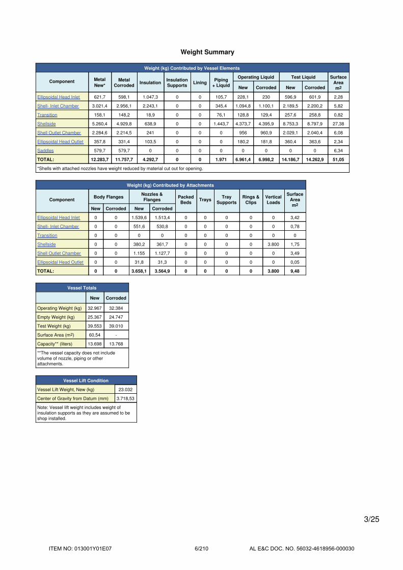
Weight Summary
Weight (kg) Contributed by Vessel Elements
Component Metal
New*
Metal
CorrodedInsulation
Insulation
SupportsLining
Piping
+ Liquid
Operating Liquid Test Liquid Surface
Area
m2New Corroded New Corroded
Ellipsoidal Head Inlet 621,7 598,1 1.047,3 0 0 105,7 228,1 230 596,9 601,9 2,28
Shell- Inlet Chamber 3.021,4 2.956,1 2.243,1 0 0 345,4 1.094,8 1.100,1 2.189,5 2.200,2 5,82
Transition 158,1 148,2 18,9 0 0 76,1 128,8 129,4 257,6 258,8 0,82
Shellside 5.260,4 4.929,8 638,9 0 0 1.443,7 4.373,7 4.395,9 8.753,3 8.797,9 27,38
Shell Outlet Chamber 2.284,6 2.214,5 241 0 0 0 956 960,9 2.029,1 2.040,4 6,08
Ellipsoidal Head Outlet 357,8 331,4 103,5 0 0 0 180,2 181,8 360,4 363,6 2,34
Saddles 579,7 579,7 0 0 0 0 0 0 0 0 6,34
TOTAL: 12.283,7 11.757,7 4.292,7 0 0 1.971 6.961,4 6.998,2 14.186,7 14.262,9 51,05
*Shells with attached nozzles have weight reduced by material cut out for opening.
Weight (kg) Contributed by Attachments
ComponentBody Flanges
Nozzles &
FlangesPacked
BedsTrays
Tray
Supports
Rings &
Clips
Vertical
Loads
Surface
Area
m2New Corroded New Corroded
Ellipsoidal Head Inlet 0 0 1.539,6 1.513,4 0 0 0 0 0 3,42
Shell- Inlet Chamber 0 0 551,6 530,8 0 0 0 0 0 0,78
Transition 0 0 0 0 0 0 0 0 0 0
Shellside 0 0 380,2 361,7 0 0 0 0 3.800 1,75
Shell Outlet Chamber 0 0 1.155 1.127,7 0 0 0 0 0 3,49
Ellipsoidal Head Outlet 0 0 31,8 31,3 0 0 0 0 0 0,05
TOTAL: 0 0 3.658,1 3.564,9 0 0 0 0 3.800 9,48
Vessel Totals
New Corroded
Operating Weight (kg) 32.967 32.384
Empty Weight (kg) 25.367 24.747
Test Weight (kg) 39.553 39.010
Surface Area (m2) 60,54 -
Capacity** (liters) 13.698 13.768
**The vessel capacity does not include
volume of nozzle, piping or other
attachments.
Vessel Lift Condition
Vessel Lift Weight, New (kg) 23.032
Center of Gravity from Datum (mm) 3.718,53
Note: Vessel lift weight includes weight of
insulation supports as they are assumed to be
shop installed.
3/25
ITEM NO: 013001Y01E07 6/210 AL E&C DOC. NO. 56032-4618956-000030

Wind Code
Building Code: ASCE 7-95
Elevation of base above grade 16,40 ft (5,00 m)
Increase effective outer diameter by 1,64 ft (0,50 m)
Wind Force Coefficient, Cf 0,5900
Basic Wind Speed, V 61,5157 mph (99,0000 km/h)
Importance Factor, I 1,1500
Exposure Category C
Topographic Factor, Kzt 1,0000
Enforce minimum design load of 0.48 kPa per ASCE 6.4.1.2.: Yes
Hazardous, toxic, or explosive contents No
Wind Pressure (WP) Calculations
Kz = 2,01 * (Z/zg)2/α
= 2,01 * (6,86 / 274,32)0,2105
= 0,9244
qz = 0,613 * Kz * Kzt * V2 * I / 1000
= 0,613 * 0,9244 * 1,0000 * 27,50002 * 1,1500 /
1000
= 0,4931 kPa
qz = max[ 0,4931, 0,4788 ]
= 0,4931 kPa
Table Lookup Values
α = 9,5000, zg = 274,32 m [Table C6-2, page 152]
Shear calculations are reported in the saddle report.
4/25
ITEM NO: 013001Y01E07 7/210 AL E&C DOC. NO. 56032-4618956-000030

Saddles
ASME Section VIII Division 1, 2013 Edition Metric
Saddle Material SA 516 Gr 60
Saddle Construction Centered web
Welded to Vessel Yes
Saddle Allowable Stress, Ss 1.406 kgf/cm2
Saddle Yield Stress, Sy 2.672 kgf/cm2
Foundation Allowable Stress 117 kgf/cm2
Design
PressureLeft Saddle Right Saddle
Operating 30,93 bar 30,93 bar
Test 41,51 bar 41,51 bar
Vacuum 1 bar
Dimensions
Right saddle distance to datum 7.600 mm
Tangent To Tangent Length, L 9.790,8 mm
Saddle separation, Ls 6.900 mm
Vessel Radius, R 750 mm
Tangent Distance Left, Al 750,8 mm
Tangent Distance Right, Ar 2.140 mm
Saddle Height, Hs 1.105 mm
Saddle Contact Angle, θ 85°
Web Plate Thickness, ts 20 mm
Base Plate Length, E 1.310 mm
Base Plate Width, F 300 mm
Base Plate Thickness, tb 20 mm
Number of Stiffening Ribs, n 4
Largest Stiffening Rib Spacing, di 425 mm
Stiffening Rib Thickness, tw 20 mm
Saddle Width, b 270 mm
Reinforcing Plate
Thickness, tp 20 mm
Width, Wp 400 mm
Contact Angle, θw 90°
Bolting
5/25
ITEM NO: 013001Y01E07 8/210 AL E&C DOC. NO. 56032-4618956-000030

Material A283
Bolt Allowable Shear 1.055 kgf/cm2
Description 30 mm
Corrosion on root 1,6 mm
Anchor Bolts per Saddle 4
Base coefficient of friction, µ 0,45
Weight
Operating,
CorrodedHydrotest
Weight on Left Saddle 16.816,94 kg 19.874,15 kg
Weight on Right Saddle 14.988,05 kg 19.099,42 kg
Weight of Saddle Pair 579,69 kg
Notes
(1) Saddle calculations are based on the method presented in "Stresses in Large Cylindrical Pressure Vessels on
Two Saddle Supports" by L.P. Zick.
6/25
ITEM NO: 013001Y01E07 9/210 AL E&C DOC. NO. 56032-4618956-000030
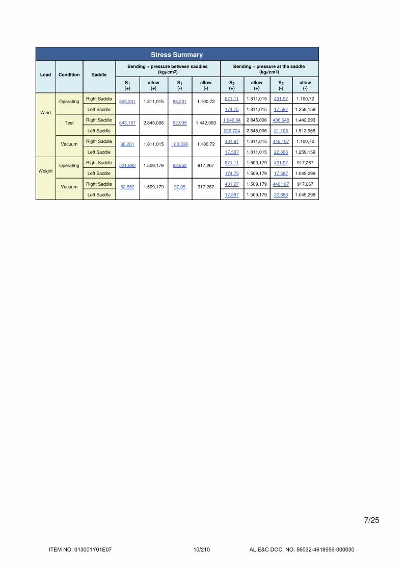
Stress Summary
Load Condition Saddle
Bending + pressure between saddles
(kgf/cm2)
Bending + pressure at the saddle
(kgf/cm2)
S1
(+)
allow
(+)
S1
(-)
allow
(-)
S2
(+)
allow
(+)
S2
(-)
allow
(-)
Wind
OperatingRight Saddle
525,341 1.811,015 86,201 1.100,72871,11 1.811,015 431,97 1.100,72
Left Saddle 174,75 1.811,015 17,587 1.259,159
TestRight Saddle
643,197 2.845,006 92,905 1.442,0931.046,94 2.845,006 496,648 1.442,093
Left Saddle 226,724 2.845,006 21,105 1.513,968
VacuumRight Saddle
86,201 1.811,015 100,398 1.100,72431,97 1.811,015 446,167 1.100,72
Left Saddle 17,587 1.811,015 22,668 1.259,159
Weight
OperatingRight Saddle
521,992 1.509,179 82,852 917,267871,11 1.509,179 431,97 917,267
Left Saddle 174,75 1.509,179 17,587 1.049,299
VacuumRight Saddle
82,852 1.509,179 97,05 917,267431,97 1.509,179 446,167 917,267
Left Saddle 17,587 1.509,179 22,668 1.049,299
7/25
ITEM NO: 013001Y01E07 10/210 AL E&C DOC. NO. 56032-4618956-000030

Stress Summary
Load Condition Saddle
Tangential
shear (kgf/cm2)
Circumferential
stress (kgf/cm2)
Stress over
saddle (kgf/cm2)Splitting (kgf/cm2)
S3 allowS4
(horns)
allow
(+/-)S5 allow S6 allow
Wind
OperatingRight Saddle 114,209 1.207,343 -422,49 2.263,768 121,325 1.279,743 18,035 937,425
Left Saddle 60,602 1.207,343 -59,905 2.263,768 50,323 1.279,743 19,058 937,425
TestRight Saddle 129,878 2.276,005 -453,271 2.845,006 140,249 2.404,496 21,985 2.404,496
Left Saddle 67,11 2.276,005 -65,89 2.845,006 56,16 2.404,496 21,892 2.404,496
VacuumRight Saddle 114,209 1.207,343 -422,49 2.263,768 121,325 1.279,743 18,035 937,425
Left Saddle 60,602 1.207,343 -59,905 2.263,768 50,323 1.279,743 19,058 937,425
Weight
OperatingRight Saddle 101,798 1.207,343 -397,733 2.263,768 114,215 1.279,743 16,978 937,425
Left Saddle 57,736 1.207,343 -57,578 2.263,768 48,368 1.279,743 18,318 937,425
VacuumRight Saddle 101,798 1.207,343 -397,733 2.263,768 114,215 1.279,743 16,978 937,425
Left Saddle 57,736 1.207,343 -57,578 2.263,768 48,368 1.279,743 18,318 937,425
8/25
ITEM NO: 013001Y01E07 11/210 AL E&C DOC. NO. 56032-4618956-000030
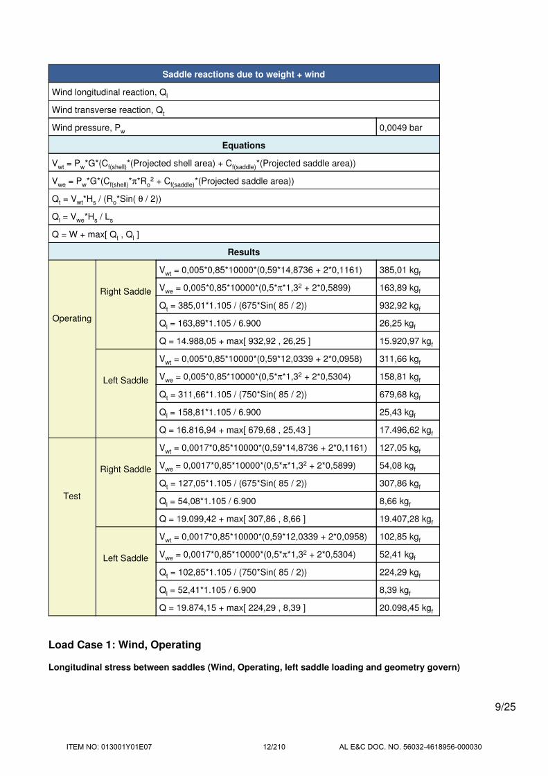
Saddle reactions due to weight + wind
Wind longitudinal reaction, Ql
Wind transverse reaction, Qt
Wind pressure, Pw 0,0049 bar
Equations
Vwt = Pw*G*(Cf(shell)*(Projected shell area) + Cf(saddle)*(Projected saddle area))
Vwe = Pw*G*(Cf(shell)*π*Ro2 + Cf(saddle)*(Projected saddle area))
Qt = Vwt*Hs / (Ro*Sin( θ / 2))
Ql = Vwe*Hs / Ls
Q = W + max[ Qt , Ql ]
Results
Operating
Right Saddle
Vwt = 0,005*0,85*10000*(0,59*14,8736 + 2*0,1161) 385,01 kgf
Vwe = 0,005*0,85*10000*(0,5*π*1,32 + 2*0,5899) 163,89 kgf
Qt = 385,01*1.105 / (675*Sin( 85 / 2)) 932,92 kgf
Ql = 163,89*1.105 / 6.900 26,25 kgf
Q = 14.988,05 + max[ 932,92 , 26,25 ] 15.920,97 kgf
Left Saddle
Vwt = 0,005*0,85*10000*(0,59*12,0339 + 2*0,0958) 311,66 kgf
Vwe = 0,005*0,85*10000*(0,5*π*1,32 + 2*0,5304) 158,81 kgf
Qt = 311,66*1.105 / (750*Sin( 85 / 2)) 679,68 kgf
Ql = 158,81*1.105 / 6.900 25,43 kgf
Q = 16.816,94 + max[ 679,68 , 25,43 ] 17.496,62 kgf
Test
Right Saddle
Vwt = 0,0017*0,85*10000*(0,59*14,8736 + 2*0,1161) 127,05 kgf
Vwe = 0,0017*0,85*10000*(0,5*π*1,32 + 2*0,5899) 54,08 kgf
Qt = 127,05*1.105 / (675*Sin( 85 / 2)) 307,86 kgf
Ql = 54,08*1.105 / 6.900 8,66 kgf
Q = 19.099,42 + max[ 307,86 , 8,66 ] 19.407,28 kgf
Left Saddle
Vwt = 0,0017*0,85*10000*(0,59*12,0339 + 2*0,0958) 102,85 kgf
Vwe = 0,0017*0,85*10000*(0,5*π*1,32 + 2*0,5304) 52,41 kgf
Qt = 102,85*1.105 / (750*Sin( 85 / 2)) 224,29 kgf
Ql = 52,41*1.105 / 6.900 8,39 kgf
Q = 19.874,15 + max[ 224,29 , 8,39 ] 20.098,45 kgf
Load Case 1: Wind, Operating
Longitudinal stress between saddles (Wind, Operating, left saddle loading and geometry govern)
9/25
ITEM NO: 013001Y01E07 12/210 AL E&C DOC. NO. 56032-4618956-000030

S1 = ± 3*K1*Q*(L / 12) / (π*R2*t)
= 300*0,651*17.496,62*(9.790,8 / 12) / (π*663,32*23,4)
= 86,201 kgf/cm2
Sp = P*R / (2*t)
= 31,54*651,6 / (2*23,4)
= 439,14 kgf/cm2
Maximum tensile stress S1t = S1 + Sp = 525,341 kgf/cm2
Maximum compressive stress (shut down) S1c = S1 = 86,201 kgf/cm2
Tensile stress is acceptable ( ≤ 1,2*S*E = 1.811,015 kgf/cm2)
Compressive stress is acceptable ( ≤ 1,2*Sc = 1.100,72 kgf/cm2)
Longitudinal stress at the right saddle (Wind, Operating)
Le = 2*(Left head depth) / 3 + L + 2*(Right head depth) / 3
= 2*390 / 3 + 9.790,8 + 2*347,5 / 3
= 10.282,47 mm
w = Wt / Le = 31.804,99*10 / 10.282,47 = 30,93 kgf/cm
Bending moment at the right saddle:
Mq = w*(2*H*Ar / 3 + Ar2 / 2 - (R2 - H2) / 4)
= 30,93 / 10000*(2*347,5*2.140 / 3 + 2.1402 / 2 - (6752 - 347,52) / 4)
= 8.357,1 kgf-m
S2 = ± Mq*K1' / (π*R2*t)
= 8.357,1*1e5*16,7177 / (π*663,32*23,4)
= 431,97 kgf/cm2
Sp = P*R / (2*t)
= 31,54*651,6 / (2*23,4)
= 439,14 kgf/cm2
Maximum tensile stress S2t = S2 + Sp = 871,11 kgf/cm2
Maximum compressive stress (shut down) S2c = S2 = 431,97 kgf/cm2
Tensile stress is acceptable ( ≤ 1,2*S = 1.811,015 kgf/cm2)
Compressive stress is acceptable ( ≤ 1,2*Sc = 1.100,72 kgf/cm2)
Tangential shear stress in the shell (right saddle, Wind, Operating)
Qshear = Q - w*(a + 2*H / 3)
= 15.920,97 - 3,09*(2.140 + 2*347,5 / 3)
= 8.585,1 kgf
S3 = K2,2*Qshear / (R*t)
= K2,2*100*8.585,1 / (663,3*23,4)
= 114,209 kgf/cm2
Tangential shear stress is acceptable ( ≤ 0.8*S = 1.207,343 kgf/cm2)
Circumferential stress at the right saddle horns (Wind, Operating)
S4 = -Q / (4*t*(b+1,56*Sqr(Ro*t))) - 3*K3*Q / (2*t2)
10/25
ITEM NO: 013001Y01E07 13/210 AL E&C DOC. NO. 56032-4618956-000030

= -100*15.920,97 / (4*23,4*(270+1,56*Sqr(675*23,4))) - 3*0,0885*100*15.920,97 / (2*23,42)
= -422,49 kgf/cm2
Circumferential stress at saddle horns is acceptable ( ≤ 1,5*Sa = 2.263,768 kgf/cm2)
The wear plate was not considered in the calculation of S4 because the wear plate contact angle did not exceed the
saddle contact angle by at least 11,46° and the wear plate width is not at least {b + 1,56*(Ro*t)0,5} =466,06 mm
Ring compression in shell over right saddle (Wind, Operating)
S5 = K5*Q / ((t + tp)*(ts + 1,56*Sqr(Ro*tc)))
= 100*0,9492*15.920,97 / ((23,4 + 20)*(20 + 1,56*Sqr(675*43,4)))
= 121,325 kgf/cm2
Ring compression in shell is acceptable ( ≤ 0,5*Sy = 1.279,743 kgf/cm2)
Saddle splitting load (right, Wind, Operating)
Area resisting splitting force = Web area + wear plate area
Ae = Heff*ts + tp*Wp
= 22,5*2 + 2*40
= 125 cm2
S6 = K8*Q / Ae
= 100*0,1416*15.920,97 / 12.500
= 18,035 kgf/cm2
Stress in saddle is acceptable ( ≤ (2 / 3)*Ss = 937,425 kgf/cm2)
Longitudinal stress at the left saddle (Wind, Operating)
Le = 2*(Left head depth) / 3 + L + 2*(Right head depth) / 3
= 2*390 / 3 + 9.790,8 + 2*347,5 / 3
= 10.282,47 mm
w = Wt / Le = 31.804,99*10 / 10.282,47 = 30,93 kgf/cm
Bending moment at the left saddle:
Mq = w*(2*H*Al / 3 + Al2 / 2 - (R2 - H2) / 4)
= 30,93 / 10000*(2*390*750,8 / 3 + 750,82 / 2 - (7502 - 3902) / 4)
= 1.158,2 kgf-m
S2 = ± Mq*K1' / (π*R2*t)
= 1.158,2*1e5*16,7177 / (π*715,82*68,4)
= 17,587 kgf/cm2
Sp = P*R / (2*t)
= 31,54*681,6 / (2*68,4)
= 157,163 kgf/cm2
Maximum tensile stress S2t = S2 + Sp = 174,75 kgf/cm2
Maximum compressive stress (shut down) S2c = S2 = 17,587 kgf/cm2
Tensile stress is acceptable ( ≤ 1,2*S = 1.811,015 kgf/cm2)
Compressive stress is acceptable ( ≤ 1,2*Sc = 1.259,159 kgf/cm2)
11/25
ITEM NO: 013001Y01E07 14/210 AL E&C DOC. NO. 56032-4618956-000030

Tangential shear stress in the shell (left saddle, Wind, Operating)
Qshear = Q - w*(a + 2*H / 3)
= 17.496,62 - 3,09*(750,8 + 2*390 / 3)
= 14.370,09 kgf
S3 = K2,2*Qshear / (R*t)
= K2,2*100*14.370,09 / (715,8*68,4)
= 60,602 kgf/cm2
Tangential shear stress is acceptable ( ≤ 0.8*S = 1.207,343 kgf/cm2)
Circumferential stress at the left saddle horns (Wind, Operating)
S4 = -Q / (4*t*(b+1,56*Sqr(Ro*t))) - 3*K3*Q / (2*t2)
= -100*17.496,62 / (4*68,4*(270+1,56*Sqr(750*68,4))) - 3*0,0885*100*17.496,62 / (2*68,42)
= -59,905 kgf/cm2
Circumferential stress at saddle horns is acceptable ( ≤ 1,5*Sa = 2.263,768 kgf/cm2)
The wear plate was not considered in the calculation of S4 because the wear plate contact angle did not exceed the
saddle contact angle by at least 11,46° and the wear plate width is not at least {b + 1,56*(Ro*t)0,5} =623,33 mm
Ring compression in shell over left saddle (Wind, Operating)
S5 = K5*Q / ((t + tp)*(ts + 1,56*Sqr(Ro*tc)))
= 100*0,9492*17.496,62 / ((68,4 + 20)*(20 + 1,56*Sqr(750*68,4)))
= 50,323 kgf/cm2
Ring compression in shell is acceptable ( ≤ 0,5*Sy = 1.279,743 kgf/cm2)
Saddle splitting load (left, Wind, Operating)
Area resisting splitting force = Web area + wear plate area
Ae = Heff*ts + tp*Wp
= 25*2 + 2*40
= 130 cm2
S6 = K8*Q / Ae
= 100*0,1416*17.496,62 / 13.000
= 19,058 kgf/cm2
Stress in saddle is acceptable ( ≤ (2 / 3)*Ss = 937,425 kgf/cm2)
Load Case 2: Wind, Test
Longitudinal stress between saddles (Wind, Test, left saddle loading and geometry govern)
S1 = ± 3*K1*Q*(L / 12) / (π*R2*t)
= 300*0,651*20.098,45*(9.790,8 / 12) / (π*662,52*25)
= 92,905 kgf/cm2
Sp = P*R / (2*t)
= 42,33*650 / (2*25)
= 550,292 kgf/cm2
Maximum tensile stress S1t = S1 + Sp = 643,197 kgf/cm2
12/25
ITEM NO: 013001Y01E07 15/210 AL E&C DOC. NO. 56032-4618956-000030
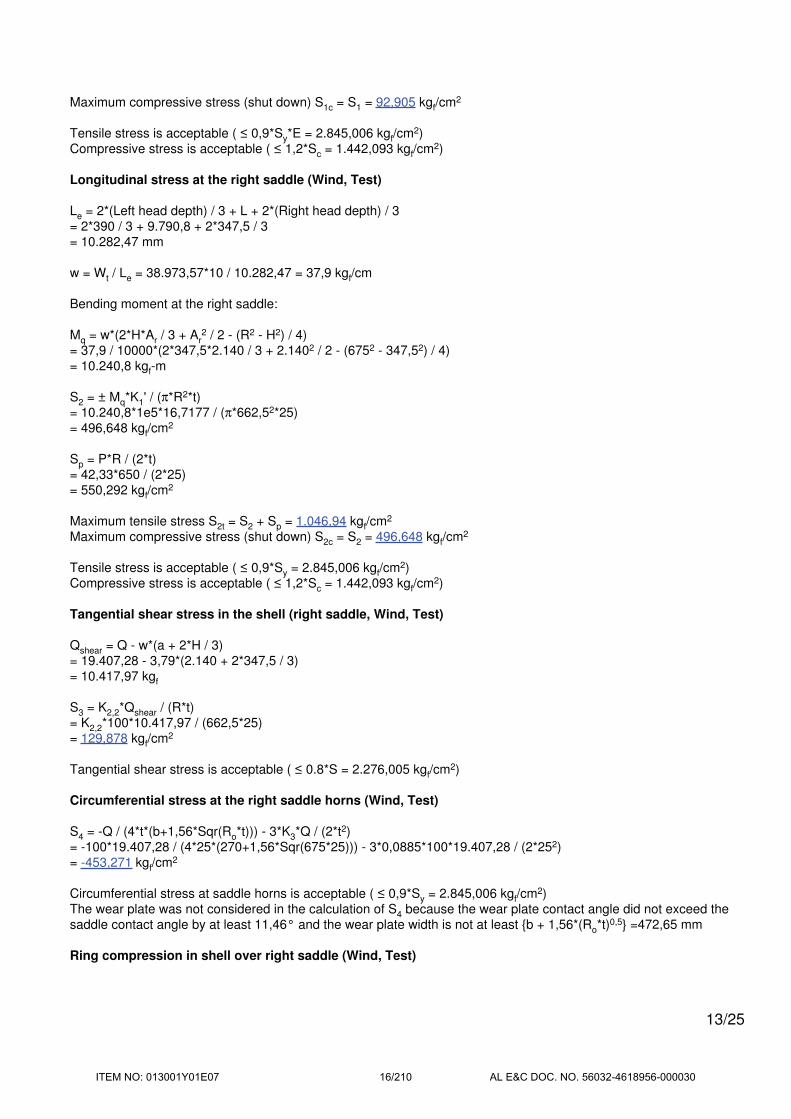
Maximum compressive stress (shut down) S1c = S1 = 92,905 kgf/cm2
Tensile stress is acceptable ( ≤ 0,9*Sy*E = 2.845,006 kgf/cm2)
Compressive stress is acceptable ( ≤ 1,2*Sc = 1.442,093 kgf/cm2)
Longitudinal stress at the right saddle (Wind, Test)
Le = 2*(Left head depth) / 3 + L + 2*(Right head depth) / 3
= 2*390 / 3 + 9.790,8 + 2*347,5 / 3
= 10.282,47 mm
w = Wt / Le = 38.973,57*10 / 10.282,47 = 37,9 kgf/cm
Bending moment at the right saddle:
Mq = w*(2*H*Ar / 3 + Ar2 / 2 - (R2 - H2) / 4)
= 37,9 / 10000*(2*347,5*2.140 / 3 + 2.1402 / 2 - (6752 - 347,52) / 4)
= 10.240,8 kgf-m
S2 = ± Mq*K1' / (π*R2*t)
= 10.240,8*1e5*16,7177 / (π*662,52*25)
= 496,648 kgf/cm2
Sp = P*R / (2*t)
= 42,33*650 / (2*25)
= 550,292 kgf/cm2
Maximum tensile stress S2t = S2 + Sp = 1.046,94 kgf/cm2
Maximum compressive stress (shut down) S2c = S2 = 496,648 kgf/cm2
Tensile stress is acceptable ( ≤ 0,9*Sy = 2.845,006 kgf/cm2)
Compressive stress is acceptable ( ≤ 1,2*Sc = 1.442,093 kgf/cm2)
Tangential shear stress in the shell (right saddle, Wind, Test)
Qshear = Q - w*(a + 2*H / 3)
= 19.407,28 - 3,79*(2.140 + 2*347,5 / 3)
= 10.417,97 kgf
S3 = K2,2*Qshear / (R*t)
= K2,2*100*10.417,97 / (662,5*25)
= 129,878 kgf/cm2
Tangential shear stress is acceptable ( ≤ 0.8*S = 2.276,005 kgf/cm2)
Circumferential stress at the right saddle horns (Wind, Test)
S4 = -Q / (4*t*(b+1,56*Sqr(Ro*t))) - 3*K3*Q / (2*t2)
= -100*19.407,28 / (4*25*(270+1,56*Sqr(675*25))) - 3*0,0885*100*19.407,28 / (2*252)
= -453,271 kgf/cm2
Circumferential stress at saddle horns is acceptable ( ≤ 0,9*Sy = 2.845,006 kgf/cm2)
The wear plate was not considered in the calculation of S4 because the wear plate contact angle did not exceed the
saddle contact angle by at least 11,46° and the wear plate width is not at least {b + 1,56*(Ro*t)0,5} =472,65 mm
Ring compression in shell over right saddle (Wind, Test)
13/25
ITEM NO: 013001Y01E07 16/210 AL E&C DOC. NO. 56032-4618956-000030

S5 = K5*Q / ((t + tp)*(ts + 1,56*Sqr(Ro*tc)))
= 100*0,9492*19.407,28 / ((25 + 20)*(20 + 1,56*Sqr(675*45)))
= 140,249 kgf/cm2
Ring compression in shell is acceptable ( ≤ 0,9*Sy = 2.404,496 kgf/cm2)
Saddle splitting load (right, Wind, Test)
Area resisting splitting force = Web area + wear plate area
Ae = Heff*ts + tp*Wp
= 22,5*2 + 2*40
= 125 cm2
S6 = K8*Q / Ae
= 100*0,1416*19.407,28 / 12.500
= 21,985 kgf/cm2
Stress in saddle is acceptable ( ≤ 0,9*Sy = 2.404,496 kgf/cm2)
Longitudinal stress at the left saddle (Wind, Test)
Le = 2*(Left head depth) / 3 + L + 2*(Right head depth) / 3
= 2*390 / 3 + 9.790,8 + 2*347,5 / 3
= 10.282,47 mm
w = Wt / Le = 38.973,57*10 / 10.282,47 = 37,9 kgf/cm
Bending moment at the left saddle:
Mq = w*(2*H*Al / 3 + Al2 / 2 - (R2 - H2) / 4)
= 37,9 / 10000*(2*390*750,8 / 3 + 750,82 / 2 - (7502 - 3902) / 4)
= 1.419,3 kgf-m
S2 = ± Mq*K1' / (π*R2*t)
= 1.419,3*1e5*16,7177 / (π*7152*70)
= 21,105 kgf/cm2
Sp = P*R / (2*t)
= 42,33*680 / (2*70)
= 205,618 kgf/cm2
Maximum tensile stress S2t = S2 + Sp = 226,724 kgf/cm2
Maximum compressive stress (shut down) S2c = S2 = 21,105 kgf/cm2
Tensile stress is acceptable ( ≤ 0,9*Sy = 2.845,006 kgf/cm2)
Compressive stress is acceptable ( ≤ 1,2*Sc = 1.513,968 kgf/cm2)
Tangential shear stress in the shell (left saddle, Wind, Test)
Qshear = Q - w*(a + 2*H / 3)
= 20.098,45 - 3,79*(750,8 + 2*390 / 3)
= 16.267,22 kgf
S3 = K2,2*Qshear / (R*t)
= K2,2*100*16.267,22 / (715*70)
= 67,11 kgf/cm2
14/25
ITEM NO: 013001Y01E07 17/210 AL E&C DOC. NO. 56032-4618956-000030

Tangential shear stress is acceptable ( ≤ 0.8*S = 2.276,005 kgf/cm2)
Circumferential stress at the left saddle horns (Wind, Test)
S4 = -Q / (4*t*(b+1,56*Sqr(Ro*t))) - 3*K3*Q / (2*t2)
= -100*20.098,45 / (4*70*(270+1,56*Sqr(750*70))) - 3*0,0885*100*20.098,45 / (2*702)
= -65,89 kgf/cm2
Circumferential stress at saddle horns is acceptable ( ≤ 0,9*Sy = 2.845,006 kgf/cm2)
The wear plate was not considered in the calculation of S4 because the wear plate contact angle did not exceed the
saddle contact angle by at least 11,46° and the wear plate width is not at least {b + 1,56*(Ro*t)0,5} =627,44 mm
Ring compression in shell over left saddle (Wind, Test)
S5 = K5*Q / ((t + tp)*(ts + 1,56*Sqr(Ro*tc)))
= 100*0,9492*20.098,45 / ((70 + 20)*(20 + 1,56*Sqr(750*70)))
= 56,16 kgf/cm2
Ring compression in shell is acceptable ( ≤ 0,9*Sy = 2.404,496 kgf/cm2)
Saddle splitting load (left, Wind, Test)
Area resisting splitting force = Web area + wear plate area
Ae = Heff*ts + tp*Wp
= 25*2 + 2*40
= 130 cm2
S6 = K8*Q / Ae
= 100*0,1416*20.098,45 / 13.000
= 21,892 kgf/cm2
Stress in saddle is acceptable ( ≤ 0,9*Sy = 2.404,496 kgf/cm2)
Load Case 3: Wind, Vacuum
Longitudinal stress between saddles (Wind, Vacuum, left saddle loading and geometry govern)
S1 = ± 3*K1*Q*(L / 12) / (π*R2*t)
= 300*0,651*17.496,62*(9.790,8 / 12) / (π*663,32*23,4)
= 86,201 kgf/cm2
Sp = P*R / (2*t)
= 1,02*651,6 / (2*23,4)
= 14,198 kgf/cm2
Maximum tensile stress (shut down) S1t = S1 = 86,201 kgf/cm2
Maximum compressive stress S1c = S1 + Sp = 100,398 kgf/cm2
Tensile stress is acceptable ( ≤ 1,2*S*E = 1.811,015 kgf/cm2)
Compressive stress is acceptable ( ≤ 1,2*Sc = 1.100,72 kgf/cm2)
Longitudinal stress at the right saddle (Wind, Vacuum)
Le = 2*(Left head depth) / 3 + L + 2*(Right head depth) / 3
= 2*390 / 3 + 9.790,8 + 2*347,5 / 3
15/25
ITEM NO: 013001Y01E07 18/210 AL E&C DOC. NO. 56032-4618956-000030

= 10.282,47 mm
w = Wt / Le = 31.804,99*10 / 10.282,47 = 30,93 kgf/cm
Bending moment at the right saddle:
Mq = w*(2*H*Ar / 3 + Ar2 / 2 - (R2 - H2) / 4)
= 30,93 / 10000*(2*347,5*2.140 / 3 + 2.1402 / 2 - (6752 - 347,52) / 4)
= 8.357,1 kgf-m
S2 = ± Mq*K1' / (π*R2*t)
= 8.357,1*1e5*16,7177 / (π*663,32*23,4)
= 431,97 kgf/cm2
Sp = P*R / (2*t)
= 1,02*651,6 / (2*23,4)
= 14,198 kgf/cm2
Maximum tensile stress (shut down) S2t = S2 = 431,97 kgf/cm2
Maximum compressive stress S2c = S2 + Sp = 446,167 kgf/cm2
Tensile stress is acceptable ( ≤ 1,2*S = 1.811,015 kgf/cm2)
Compressive stress is acceptable ( ≤ 1,2*Sc = 1.100,72 kgf/cm2)
Tangential shear stress in the shell (right saddle, Wind, Vacuum)
Qshear = Q - w*(a + 2*H / 3)
= 15.920,97 - 3,09*(2.140 + 2*347,5 / 3)
= 8.585,1 kgf
S3 = K2,2*Qshear / (R*t)
= K2,2*100*8.585,1 / (663,3*23,4)
= 114,209 kgf/cm2
Tangential shear stress is acceptable ( ≤ 0.8*S = 1.207,343 kgf/cm2)
Circumferential stress at the right saddle horns (Wind, Vacuum)
S4 = -Q / (4*t*(b+1,56*Sqr(Ro*t))) - 3*K3*Q / (2*t2)
= -100*15.920,97 / (4*23,4*(270+1,56*Sqr(675*23,4))) - 3*0,0885*100*15.920,97 / (2*23,42)
= -422,49 kgf/cm2
Circumferential stress at saddle horns is acceptable ( ≤ 1,5*Sa = 2.263,768 kgf/cm2)
The wear plate was not considered in the calculation of S4 because the wear plate contact angle did not exceed the
saddle contact angle by at least 11,46° and the wear plate width is not at least {b + 1,56*(Ro*t)0,5} =466,06 mm
Ring compression in shell over right saddle (Wind, Vacuum)
S5 = K5*Q / ((t + tp)*(ts + 1,56*Sqr(Ro*tc)))
= 100*0,9492*15.920,97 / ((23,4 + 20)*(20 + 1,56*Sqr(675*43,4)))
= 121,325 kgf/cm2
Ring compression in shell is acceptable ( ≤ 0,5*Sy = 1.279,743 kgf/cm2)
Saddle splitting load (right, Wind, Vacuum)
Area resisting splitting force = Web area + wear plate area
16/25
ITEM NO: 013001Y01E07 19/210 AL E&C DOC. NO. 56032-4618956-000030

Ae = Heff*ts + tp*Wp
= 22,5*2 + 2*40
= 125 cm2
S6 = K8*Q / Ae
= 100*0,1416*15.920,97 / 12.500
= 18,035 kgf/cm2
Stress in saddle is acceptable ( ≤ (2 / 3)*Ss = 937,425 kgf/cm2)
Longitudinal stress at the left saddle (Wind, Vacuum)
Le = 2*(Left head depth) / 3 + L + 2*(Right head depth) / 3
= 2*390 / 3 + 9.790,8 + 2*347,5 / 3
= 10.282,47 mm
w = Wt / Le = 31.804,99*10 / 10.282,47 = 30,93 kgf/cm
Bending moment at the left saddle:
Mq = w*(2*H*Al / 3 + Al2 / 2 - (R2 - H2) / 4)
= 30,93 / 10000*(2*390*750,8 / 3 + 750,82 / 2 - (7502 - 3902) / 4)
= 1.158,2 kgf-m
S2 = ± Mq*K1' / (π*R2*t)
= 1.158,2*1e5*16,7177 / (π*715,82*68,4)
= 17,587 kgf/cm2
Sp = P*R / (2*t)
= 1,02*681,6 / (2*68,4)
= 5,081 kgf/cm2
Maximum tensile stress (shut down) S2t = S2 = 17,587 kgf/cm2
Maximum compressive stress S2c = S2 + Sp = 22,668 kgf/cm2
Tensile stress is acceptable ( ≤ 1,2*S = 1.811,015 kgf/cm2)
Compressive stress is acceptable ( ≤ 1,2*Sc = 1.259,159 kgf/cm2)
Tangential shear stress in the shell (left saddle, Wind, Vacuum)
Qshear = Q - w*(a + 2*H / 3)
= 17.496,62 - 3,09*(750,8 + 2*390 / 3)
= 14.370,09 kgf
S3 = K2,2*Qshear / (R*t)
= K2,2*100*14.370,09 / (715,8*68,4)
= 60,602 kgf/cm2
Tangential shear stress is acceptable ( ≤ 0.8*S = 1.207,343 kgf/cm2)
Circumferential stress at the left saddle horns (Wind, Vacuum)
S4 = -Q / (4*t*(b+1,56*Sqr(Ro*t))) - 3*K3*Q / (2*t2)
= -100*17.496,62 / (4*68,4*(270+1,56*Sqr(750*68,4))) - 3*0,0885*100*17.496,62 / (2*68,42)
= -59,905 kgf/cm2
17/25
ITEM NO: 013001Y01E07 20/210 AL E&C DOC. NO. 56032-4618956-000030

Circumferential stress at saddle horns is acceptable ( ≤ 1,5*Sa = 2.263,768 kgf/cm2)
The wear plate was not considered in the calculation of S4 because the wear plate contact angle did not exceed the
saddle contact angle by at least 11,46° and the wear plate width is not at least {b + 1,56*(Ro*t)0,5} =623,33 mm
Ring compression in shell over left saddle (Wind, Vacuum)
S5 = K5*Q / ((t + tp)*(ts + 1,56*Sqr(Ro*tc)))
= 100*0,9492*17.496,62 / ((68,4 + 20)*(20 + 1,56*Sqr(750*68,4)))
= 50,323 kgf/cm2
Ring compression in shell is acceptable ( ≤ 0,5*Sy = 1.279,743 kgf/cm2)
Saddle splitting load (left, Wind, Vacuum)
Area resisting splitting force = Web area + wear plate area
Ae = Heff*ts + tp*Wp
= 25*2 + 2*40
= 130 cm2
S6 = K8*Q / Ae
= 100*0,1416*17.496,62 / 13.000
= 19,058 kgf/cm2
Stress in saddle is acceptable ( ≤ (2 / 3)*Ss = 937,425 kgf/cm2)
Load Case 4: Weight, Operating
Longitudinal stress between saddles (Weight, Operating, left saddle loading and geometry govern)
S1 = ± 3*K1*Q*(L / 12) / (π*R2*t)
= 300*0,651*16.816,94*(9.790,8 / 12) / (π*663,32*23,4)
= 82,852 kgf/cm2
Sp = P*R / (2*t)
= 31,54*651,6 / (2*23,4)
= 439,14 kgf/cm2
Maximum tensile stress S1t = S1 + Sp = 521,992 kgf/cm2
Maximum compressive stress (shut down) S1c = S1 = 82,852 kgf/cm2
Tensile stress is acceptable ( ≤ S*E = 1.509,179 kgf/cm2)
Compressive stress is acceptable ( ≤ Sc = 917,267 kgf/cm2)
Longitudinal stress at the right saddle (Weight, Operating)
Le = 2*(Left head depth) / 3 + L + 2*(Right head depth) / 3
= 2*390 / 3 + 9.790,8 + 2*347,5 / 3
= 10.282,47 mm
w = Wt / Le = 31.804,99*10 / 10.282,47 = 30,93 kgf/cm
Bending moment at the right saddle:
Mq = w*(2*H*Ar / 3 + Ar2 / 2 - (R2 - H2) / 4)
= 30,93 / 10000*(2*347,5*2.140 / 3 + 2.1402 / 2 - (6752 - 347,52) / 4)
= 8.357,1 kgf-m
18/25
ITEM NO: 013001Y01E07 21/210 AL E&C DOC. NO. 56032-4618956-000030

S2 = ± Mq*K1' / (π*R2*t)
= 8.357,1*1e5*16,7177 / (π*663,32*23,4)
= 431,97 kgf/cm2
Sp = P*R / (2*t)
= 31,54*651,6 / (2*23,4)
= 439,14 kgf/cm2
Maximum tensile stress S2t = S2 + Sp = 871,11 kgf/cm2
Maximum compressive stress (shut down) S2c = S2 = 431,97 kgf/cm2
Tensile stress is acceptable ( ≤ S = 1.509,179 kgf/cm2)
Compressive stress is acceptable ( ≤ Sc = 917,267 kgf/cm2)
Tangential shear stress in the shell (right saddle, Weight, Operating)
Qshear = Q - w*(a + 2*H / 3)
= 14.988,05 - 3,09*(2.140 + 2*347,5 / 3)
= 7.652,18 kgf
S3 = K2,2*Qshear / (R*t)
= K2,2*100*7.652,18 / (663,3*23,4)
= 101,798 kgf/cm2
Tangential shear stress is acceptable ( ≤ 0.8*S = 1.207,343 kgf/cm2)
Circumferential stress at the right saddle horns (Weight, Operating)
S4 = -Q / (4*t*(b+1,56*Sqr(Ro*t))) - 3*K3*Q / (2*t2)
= -100*14.988,05 / (4*23,4*(270+1,56*Sqr(675*23,4))) - 3*0,0885*100*14.988,05 / (2*23,42)
= -397,733 kgf/cm2
Circumferential stress at saddle horns is acceptable ( ≤ 1,5*Sa = 2.263,768 kgf/cm2)
The wear plate was not considered in the calculation of S4 because the wear plate contact angle did not exceed the
saddle contact angle by at least 11,46° and the wear plate width is not at least {b + 1,56*(Ro*t)0,5} =466,06 mm
Ring compression in shell over right saddle (Weight, Operating)
S5 = K5*Q / ((t + tp)*(ts + 1,56*Sqr(Ro*tc)))
= 100*0,9492*14.988,05 / ((23,4 + 20)*(20 + 1,56*Sqr(675*43,4)))
= 114,215 kgf/cm2
Ring compression in shell is acceptable ( ≤ 0,5*Sy = 1.279,743 kgf/cm2)
Saddle splitting load (right, Weight, Operating)
Area resisting splitting force = Web area + wear plate area
Ae = Heff*ts + tp*Wp
= 22,5*2 + 2*40
= 125 cm2
S6 = K8*Q / Ae
= 100*0,1416*14.988,05 / 12.500
= 16,978 kgf/cm2
19/25
ITEM NO: 013001Y01E07 22/210 AL E&C DOC. NO. 56032-4618956-000030

Stress in saddle is acceptable ( ≤ (2 / 3)*Ss = 937,425 kgf/cm2)
Longitudinal stress at the left saddle (Weight, Operating)
Le = 2*(Left head depth) / 3 + L + 2*(Right head depth) / 3
= 2*390 / 3 + 9.790,8 + 2*347,5 / 3
= 10.282,47 mm
w = Wt / Le = 31.804,99*10 / 10.282,47 = 30,93 kgf/cm
Bending moment at the left saddle:
Mq = w*(2*H*Al / 3 + Al2 / 2 - (R2 - H2) / 4)
= 30,93 / 10000*(2*390*750,8 / 3 + 750,82 / 2 - (7502 - 3902) / 4)
= 1.158,2 kgf-m
S2 = ± Mq*K1' / (π*R2*t)
= 1.158,2*1e5*16,7177 / (π*715,82*68,4)
= 17,587 kgf/cm2
Sp = P*R / (2*t)
= 31,54*681,6 / (2*68,4)
= 157,163 kgf/cm2
Maximum tensile stress S2t = S2 + Sp = 174,75 kgf/cm2
Maximum compressive stress (shut down) S2c = S2 = 17,587 kgf/cm2
Tensile stress is acceptable ( ≤ S = 1.509,179 kgf/cm2)
Compressive stress is acceptable ( ≤ Sc = 1.049,299 kgf/cm2)
Tangential shear stress in the shell (left saddle, Weight, Operating)
Qshear = Q - w*(a + 2*H / 3)
= 16.816,94 - 3,09*(750,8 + 2*390 / 3)
= 13.690,4 kgf
S3 = K2,2*Qshear / (R*t)
= K2,2*100*13.690,4 / (715,8*68,4)
= 57,736 kgf/cm2
Tangential shear stress is acceptable ( ≤ 0.8*S = 1.207,343 kgf/cm2)
Circumferential stress at the left saddle horns (Weight, Operating)
S4 = -Q / (4*t*(b+1,56*Sqr(Ro*t))) - 3*K3*Q / (2*t2)
= -100*16.816,94 / (4*68,4*(270+1,56*Sqr(750*68,4))) - 3*0,0885*100*16.816,94 / (2*68,42)
= -57,578 kgf/cm2
Circumferential stress at saddle horns is acceptable ( ≤ 1,5*Sa = 2.263,768 kgf/cm2)
The wear plate was not considered in the calculation of S4 because the wear plate contact angle did not exceed the
saddle contact angle by at least 11,46° and the wear plate width is not at least {b + 1,56*(Ro*t)0,5} =623,33 mm
Ring compression in shell over left saddle (Weight, Operating)
S5 = K5*Q / ((t + tp)*(ts + 1,56*Sqr(Ro*tc)))
= 100*0,9492*16.816,94 / ((68,4 + 20)*(20 + 1,56*Sqr(750*68,4)))
= 48,368 kgf/cm2
20/25
ITEM NO: 013001Y01E07 23/210 AL E&C DOC. NO. 56032-4618956-000030

Ring compression in shell is acceptable ( ≤ 0,5*Sy = 1.279,743 kgf/cm2)
Saddle splitting load (left, Weight, Operating)
Area resisting splitting force = Web area + wear plate area
Ae = Heff*ts + tp*Wp
= 25*2 + 2*40
= 130 cm2
S6 = K8*Q / Ae
= 100*0,1416*16.816,94 / 13.000
= 18,318 kgf/cm2
Stress in saddle is acceptable ( ≤ (2 / 3)*Ss = 937,425 kgf/cm2)
Load Case 5: Weight, Vacuum
Longitudinal stress between saddles (Weight, Vacuum, left saddle loading and geometry govern)
S1 = ± 3*K1*Q*(L / 12) / (π*R2*t)
= 300*0,651*16.816,94*(9.790,8 / 12) / (π*663,32*23,4)
= 82,852 kgf/cm2
Sp = P*R / (2*t)
= 1,02*651,6 / (2*23,4)
= 14,198 kgf/cm2
Maximum tensile stress (shut down) S1t = S1 = 82,852 kgf/cm2
Maximum compressive stress S1c = S1 + Sp = 97,05 kgf/cm2
Tensile stress is acceptable ( ≤ S*E = 1.509,179 kgf/cm2)
Compressive stress is acceptable ( ≤ Sc = 917,267 kgf/cm2)
Longitudinal stress at the right saddle (Weight, Vacuum)
Le = 2*(Left head depth) / 3 + L + 2*(Right head depth) / 3
= 2*390 / 3 + 9.790,8 + 2*347,5 / 3
= 10.282,47 mm
w = Wt / Le = 31.804,99*10 / 10.282,47 = 30,93 kgf/cm
Bending moment at the right saddle:
Mq = w*(2*H*Ar / 3 + Ar2 / 2 - (R2 - H2) / 4)
= 30,93 / 10000*(2*347,5*2.140 / 3 + 2.1402 / 2 - (6752 - 347,52) / 4)
= 8.357,1 kgf-m
S2 = ± Mq*K1' / (π*R2*t)
= 8.357,1*1e5*16,7177 / (π*663,32*23,4)
= 431,97 kgf/cm2
Sp = P*R / (2*t)
= 1,02*651,6 / (2*23,4)
= 14,198 kgf/cm2
21/25
ITEM NO: 013001Y01E07 24/210 AL E&C DOC. NO. 56032-4618956-000030

Maximum tensile stress (shut down) S2t = S2 = 431,97 kgf/cm2
Maximum compressive stress S2c = S2 + Sp = 446,167 kgf/cm2
Tensile stress is acceptable ( ≤ S = 1.509,179 kgf/cm2)
Compressive stress is acceptable ( ≤ Sc = 917,267 kgf/cm2)
Tangential shear stress in the shell (right saddle, Weight, Vacuum)
Qshear = Q - w*(a + 2*H / 3)
= 14.988,05 - 3,09*(2.140 + 2*347,5 / 3)
= 7.652,18 kgf
S3 = K2,2*Qshear / (R*t)
= K2,2*100*7.652,18 / (663,3*23,4)
= 101,798 kgf/cm2
Tangential shear stress is acceptable ( ≤ 0.8*S = 1.207,343 kgf/cm2)
Circumferential stress at the right saddle horns (Weight, Vacuum)
S4 = -Q / (4*t*(b+1,56*Sqr(Ro*t))) - 3*K3*Q / (2*t2)
= -100*14.988,05 / (4*23,4*(270+1,56*Sqr(675*23,4))) - 3*0,0885*100*14.988,05 / (2*23,42)
= -397,733 kgf/cm2
Circumferential stress at saddle horns is acceptable ( ≤ 1,5*Sa = 2.263,768 kgf/cm2)
The wear plate was not considered in the calculation of S4 because the wear plate contact angle did not exceed the
saddle contact angle by at least 11,46° and the wear plate width is not at least {b + 1,56*(Ro*t)0,5} =466,06 mm
Ring compression in shell over right saddle (Weight, Vacuum)
S5 = K5*Q / ((t + tp)*(ts + 1,56*Sqr(Ro*tc)))
= 100*0,9492*14.988,05 / ((23,4 + 20)*(20 + 1,56*Sqr(675*43,4)))
= 114,215 kgf/cm2
Ring compression in shell is acceptable ( ≤ 0,5*Sy = 1.279,743 kgf/cm2)
Saddle splitting load (right, Weight, Vacuum)
Area resisting splitting force = Web area + wear plate area
Ae = Heff*ts + tp*Wp
= 22,5*2 + 2*40
= 125 cm2
S6 = K8*Q / Ae
= 100*0,1416*14.988,05 / 12.500
= 16,978 kgf/cm2
Stress in saddle is acceptable ( ≤ (2 / 3)*Ss = 937,425 kgf/cm2)
Longitudinal stress at the left saddle (Weight, Vacuum)
Le = 2*(Left head depth) / 3 + L + 2*(Right head depth) / 3
= 2*390 / 3 + 9.790,8 + 2*347,5 / 3
= 10.282,47 mm
w = Wt / Le = 31.804,99*10 / 10.282,47 = 30,93 kgf/cm
22/25
ITEM NO: 013001Y01E07 25/210 AL E&C DOC. NO. 56032-4618956-000030

Bending moment at the left saddle:
Mq = w*(2*H*Al / 3 + Al2 / 2 - (R2 - H2) / 4)
= 30,93 / 10000*(2*390*750,8 / 3 + 750,82 / 2 - (7502 - 3902) / 4)
= 1.158,2 kgf-m
S2 = ± Mq*K1' / (π*R2*t)
= 1.158,2*1e5*16,7177 / (π*715,82*68,4)
= 17,587 kgf/cm2
Sp = P*R / (2*t)
= 1,02*681,6 / (2*68,4)
= 5,081 kgf/cm2
Maximum tensile stress (shut down) S2t = S2 = 17,587 kgf/cm2
Maximum compressive stress S2c = S2 + Sp = 22,668 kgf/cm2
Tensile stress is acceptable ( ≤ S = 1.509,179 kgf/cm2)
Compressive stress is acceptable ( ≤ Sc = 1.049,299 kgf/cm2)
Tangential shear stress in the shell (left saddle, Weight, Vacuum)
Qshear = Q - w*(a + 2*H / 3)
= 16.816,94 - 3,09*(750,8 + 2*390 / 3)
= 13.690,4 kgf
S3 = K2,2*Qshear / (R*t)
= K2,2*100*13.690,4 / (715,8*68,4)
= 57,736 kgf/cm2
Tangential shear stress is acceptable ( ≤ 0.8*S = 1.207,343 kgf/cm2)
Circumferential stress at the left saddle horns (Weight, Vacuum)
S4 = -Q / (4*t*(b+1,56*Sqr(Ro*t))) - 3*K3*Q / (2*t2)
= -100*16.816,94 / (4*68,4*(270+1,56*Sqr(750*68,4))) - 3*0,0885*100*16.816,94 / (2*68,42)
= -57,578 kgf/cm2
Circumferential stress at saddle horns is acceptable ( ≤ 1,5*Sa = 2.263,768 kgf/cm2)
The wear plate was not considered in the calculation of S4 because the wear plate contact angle did not exceed the
saddle contact angle by at least 11,46° and the wear plate width is not at least {b + 1,56*(Ro*t)0,5} =623,33 mm
Ring compression in shell over left saddle (Weight, Vacuum)
S5 = K5*Q / ((t + tp)*(ts + 1,56*Sqr(Ro*tc)))
= 100*0,9492*16.816,94 / ((68,4 + 20)*(20 + 1,56*Sqr(750*68,4)))
= 48,368 kgf/cm2
Ring compression in shell is acceptable ( ≤ 0,5*Sy = 1.279,743 kgf/cm2)
Saddle splitting load (left, Weight, Vacuum)
Area resisting splitting force = Web area + wear plate area
Ae = Heff*ts + tp*Wp
= 25*2 + 2*40
23/25
ITEM NO: 013001Y01E07 26/210 AL E&C DOC. NO. 56032-4618956-000030

= 130 cm2
S6 = K8*Q / Ae
= 100*0,1416*16.816,94 / 13.000
= 18,318 kgf/cm2
Stress in saddle is acceptable ( ≤ (2 / 3)*Ss = 937,425 kgf/cm2)
Shear stress in anchor bolting, one end slotted
Maximum seismic or wind base shear = 163,89 kgf
Thermal expansion base shear = W*µ = 17.106,78*0,45 = 7.698,05 kgf
Corroded root area for a 30 mm bolt = 4,1587 cm2 ( 4 per saddle )
Bolt shear stress = 7.698,05 / (4,1587*1*4) = 462,768 kgf/cm2
Anchor bolt stress is acceptable ( ≤ 1.054,604 kgf/cm2)
Shear stress in anchor bolting, transverse
Maximum seismic or wind base shear = 696,67 kgf
Corroded root area for a 30 mm bolt = 4,1587 cm2 ( 4 per saddle )
Bolt shear stress = 696,67 / (4,1587*2*4) = 20,94 kgf/cm2
Anchor bolt stress is acceptable ( ≤ 1.054,604 kgf/cm2)
Web plate buckling check (Escoe pg 251)
Allowable compressive stress Sc is the lesser of 1.406,138 or 5.223,543 kgf/cm2: (1.406,138)
Sc = Ki*π2*E / (12*(1 - 0,32)*(di / ts)2)
= 1,28*π2*20,39E+05 / (12*(1 - 0,32)*(425 / 20)2)
= 5.223,543 kgf/cm2
Allowable compressive load on the saddle
be = di*ts / (di*ts + 2*tw*(b - 25.4))*25.4
= 425*20 / (425*20 + 2*20*(270 - 25.4))*25.4
= 11,81
Fb = n*(As + 2*be*ts)*Sc
= 4*(5.000 + 2*11,81*20)*1.406,138
= 307.794,07 kgf
Saddle loading of 20.388,29 kgf is ≤ Fb; satisfactory.
Primary bending + axial stress in the saddle due to end loads (assumes one saddle slotted)
σb = V*(Hs - xo)*y / I + Q / A
= 158,81*(1.105 - 614,78)*135 / (100*13.175,33) + 100*17.496,62 / 38.240,94
= 53,73 kgf/cm2
The primary bending + axial stress in the saddle ≤ Ss = 1.406,138 kgf/cm2; satisfactory.
Secondary bending + axial stress in the saddle due to end loads (includes thermal expansion, assumes one
saddle slotted)
24/25
ITEM NO: 013001Y01E07 27/210 AL E&C DOC. NO. 56032-4618956-000030

σb = V*(Hs - xo)*y / I + Q / A
= 7.856,86*(1.105 - 614,78)*135 / (100*13.175,33) + 100*17.496,62 / 38.240,94
= 440,402 kgf/cm2
The secondary bending + axial stress in the saddle ≤ 2*Sy = 5.343,324 kgf/cm2; satisfactory.
Saddle base plate thickness check (Roark sixth edition, Table 26, case 7a)
where a = 425, b = 140 mm
tb = (β1*q*b2 / (1,5*Sa))0,5
= (3*5,188*1402 / (1,5*1.406,138))0,5
= 12,03 mm
The base plate thickness of 20 mm is adequate.
Foundation bearing check
Sf = Qmax / (F*E)
= 20.388,29 / (300*1.310)
= 5,188 kgf/cm2
Concrete bearing stress ≤ 116,569 kgf/cm2 ; satisfactory.
25/25
ITEM NO: 013001Y01E07 28/210 AL E&C DOC. NO. 56032-4618956-000030

BERTSCHenergy G m b H & Co KG
Herrengasse 23, 6700 Bludenz, Austria
www.bertsch.at
COMPRESS Pressure Vessel Design Calculations
Item: Process Gas Boiler
Vessel No: Shellside
Customer: Air Liquide Global E&C Solutions SHANGHAI
Contract: 4618956-000SIN
Designer: Pirker
Date: 19.01.2017
ITEM NO: 013001Y01E07 29/210 AL E&C DOC. NO. 56032-4618956-000030

Table of ContentsNozzle Schedule........................................................................................................................................................1/46
Nozzle Summary.......................................................................................................................................................2/46
Pressure Summary...................................................................................................................................................3/46
Revision History........................................................................................................................................................4/46
Radiography Summary.............................................................................................................................................5/46
Thickness Summary.................................................................................................................................................6/46
Hydrostatic Test........................................................................................................................................................7/46
Vacuum Summary.....................................................................................................................................................9/46
Shellside..................................................................................................................................................................10/46
Inspection Nozzle (A01, A02).................................................................................................................................13/46
Riser / Downcomer (R01- 02, D01-02)....................................................................................................................23/46
Blow Down Nozzle (N03, N04)................................................................................................................................36/46
i
ITEM NO: 013001Y01E07 30/210 AL E&C DOC. NO. 56032-4618956-000030
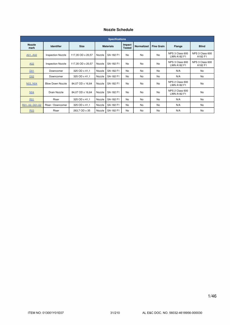
Nozzle Schedule
Specifications
Nozzle
markIdentifier Size Materials
Impact
TestedNormalized Fine Grain Flange Blind
A01, A02 Inspection Nozzle 117,35 OD x 20,57 Nozzle SA-182 F1 No No NoNPS 3 Class 600
LWN A182 F1
NPS 3 Class 600
A182 F1
A02 Inspection Nozzle 117,35 OD x 20,57 Nozzle SA-182 F1 No No NoNPS 3 Class 600
LWN A182 F1
NPS 3 Class 600
A182 F1
D01 Downcomer 325 OD x 41,1 Nozzle SA-182 F1 No No No N/A No
D02 Downcomer 325 OD x 41,1 Nozzle SA-182 F1 No No No N/A No
N03, N04 Blow Down Nozzle 84,07 OD x 16,64 Nozzle SA-182 F1 No No NoNPS 2 Class 600
LWN A182 F1No
N04 Drain Nozzle 84,07 OD x 16,64 Nozzle SA-182 F1 No No NoNPS 2 Class 600
LWN A182 F1No
R01 Riser 325 OD x 41,1 Nozzle SA-182 F1 No No No N/A No
R01- 02, D01-02 Riser / Downcomer 325 OD x 41,1 Nozzle SA-182 F1 No No No N/A No
R03 Riser 263,7 OD x 35 Nozzle SA-182 F1 No No No N/A No
1/46
ITEM NO: 013001Y01E07 31/210 AL E&C DOC. NO. 56032-4618956-000030
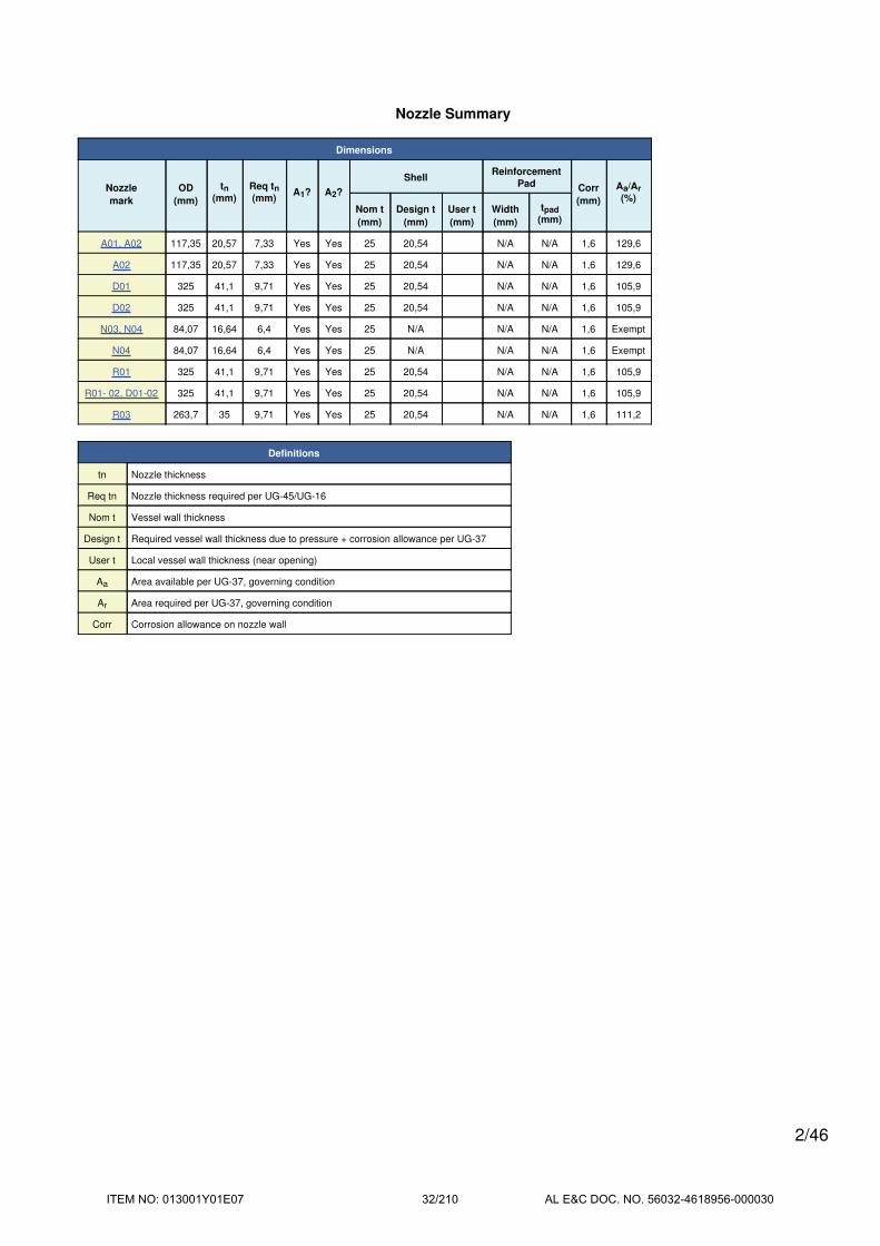
Nozzle Summary
Dimensions
Nozzle
mark
OD
(mm)
tn(mm)
Req tn(mm)
A1? A2?
ShellReinforcement
Pad Corr
(mm)
Aa/Ar
(%)Nom t
(mm)
Design t
(mm)
User t
(mm)
Width
(mm)
tpad
(mm)
A01, A02 117,35 20,57 7,33 Yes Yes 25 20,54 N/A N/A 1,6 129,6
A02 117,35 20,57 7,33 Yes Yes 25 20,54 N/A N/A 1,6 129,6
D01 325 41,1 9,71 Yes Yes 25 20,54 N/A N/A 1,6 105,9
D02 325 41,1 9,71 Yes Yes 25 20,54 N/A N/A 1,6 105,9
N03, N04 84,07 16,64 6,4 Yes Yes 25 N/A N/A N/A 1,6 Exempt
N04 84,07 16,64 6,4 Yes Yes 25 N/A N/A N/A 1,6 Exempt
R01 325 41,1 9,71 Yes Yes 25 20,54 N/A N/A 1,6 105,9
R01- 02, D01-02 325 41,1 9,71 Yes Yes 25 20,54 N/A N/A 1,6 105,9
R03 263,7 35 9,71 Yes Yes 25 20,54 N/A N/A 1,6 111,2
Definitions
tn Nozzle thickness
Req tn Nozzle thickness required per UG-45/UG-16
Nom t Vessel wall thickness
Design t Required vessel wall thickness due to pressure + corrosion allowance per UG-37
User t Local vessel wall thickness (near opening)
Aa Area available per UG-37, governing condition
Ar Area required per UG-37, governing condition
Corr Corrosion allowance on nozzle wall
2/46
ITEM NO: 013001Y01E07 32/210 AL E&C DOC. NO. 56032-4618956-000030

Pressure Summary
Component Summary
Identifier
P
Design
(bar)
T
Design
(°C)
MAWP
(bar)
MAP
(bar)
MDMT
(°C)
MDMT
Exemption
Impact
Tested
Shellside 42 260 52,03 55,64 -30,7 Note 1 Yes
Inspection Nozzle (A01, A02) 42 260 48,06 54,64 -48 Note 2 No
Inspection Nozzle (A02) 42 260 48,06 54,64 -48 Note 2 No
Downcomer (D01) 42 260 43,23 47,12 -12,2 Note 3 No
Downcomer (D02) 42 260 43,23 47,12 -12,2 Note 3 No
Blow Down Nozzle (N03, N04) 42 260 52,03 55,64 -48 Note 2 No
Drain Nozzle (N04) 42 260 52,03 55,64 -48 Note 2 No
Riser (R01) 42 260 43,23 47,12 -12,2 Note 3 No
Riser / Downcomer (R01- 02, D01-02) 42 260 43,23 47,12 -12,2 Note 3 No
Riser (R03) 42 260 44,34 48,59 -12,2 Note 3 No
Chamber Summary
Design MDMT -5,4 °C
Rated MDMT -12,2 °C @ 43,23 bar
MAWP hot & corroded 42 bar @ 260 °C
MAP cold & new 47,12 bar @ 25 °C
MAEP 1 bar
(1) The MAWP is limited due to the MAWP limit
set in the Calculations tab of the Set Mode
dialog.
Notes for Maximum Pressure Rating
Note # Details
1. Option to calculate MAEP was not selected. See the Calculation->General tab of the Set Mode dialog.
Notes for MDMT Rating
Note # Exemption Details
1. Material is impact tested per UG-84 to -20°C. UCS-66(i) reduction of 10,7°C applied (ratio = 0,8094).
2.
LWN rated MDMT per UCS-66(c)(4)
Flange rated MDMT per UCS-66(b)(1)(b) = -48°C (Coincident ratio = 0,4375)
Bolts rated MDMT per Fig UCS-66 note (c) = -48°C
3.Nozzle impact test exemption temperature from Fig UCS-66M Curve B = -1,5°C
Fig UCS-66.1M MDMT reduction = 10,7°C, (coincident ratio = 0,8094)UCS-66 governing thickness = 25 mm.
3/46
ITEM NO: 013001Y01E07 33/210 AL E&C DOC. NO. 56032-4618956-000030

Revision History
Revisions
No. Date Operator Notes
0 12/19/2016 ph New vessel created ASME Section VIII Division 1 [COMPRESS 2015 Build 7510]
4/46
ITEM NO: 013001Y01E07 34/210 AL E&C DOC. NO. 56032-4618956-000030

Radiography Summary
UG-116 Radiography
Component
Longitudinal Seam Left Circumferential Seam Right Circumferential Seam
MarkCategory
(Fig
UW-3)
Radiography / Joint
Type
Category
(Fig
UW-3)
Radiography / Joint
Type
Category
(Fig
UW-3)
Radiography / Joint
Type
Shellside AFull UW-11(a) / Type
1B
Full UW-11(a) / Type
1B
Full UW-11(a) / Type
1RT1
Nozzle Longitudinal SeamNozzle to Vessel Circumferential
Seam
Nozzle free end Circumferential
Seam
Inspection Nozzle (A01, A02) N/A Seamless No RT D N/A / Type 7 C N/A N/A
Riser (R01) N/A Seamless No RT D N/A / Type 7 N/A N/A N/A
Riser (R03) N/A Seamless No RT D N/A / Type 7 N/A N/A N/A
Riser / Downcomer (R01- 02, D01-02) N/A Seamless No RT D N/A / Type 7 N/A N/A N/A
Downcomer (D01) N/A Seamless No RT D N/A / Type 7 N/A N/A N/A
Downcomer (D02) N/A Seamless No RT D N/A / Type 7 N/A N/A N/A
Inspection Nozzle (A02) N/A Seamless No RT D N/A / Type 7 C N/A N/A
Blow Down Nozzle (N03, N04) N/A Seamless No RT D N/A / Type 7 C N/A N/A
Drain Nozzle (N04) N/A Seamless No RT D N/A / Type 7 C N/A N/A
Nozzle Flange Longitudinal Seam Flange FaceNozzle to Flange Circumferential
Seam
ASME B16.5/16.47 flange attached to
Inspection Nozzle (A01, A02)N/A Seamless No RT N/A N/A / Gasketed C N/A N/A
ASME B16.5/16.47 flange attached to
Inspection Nozzle (A02)N/A Seamless No RT N/A N/A / Gasketed C N/A N/A
ASME B16.5/16.47 flange attached to Blow
Down Nozzle (N03, N04)N/A Seamless No RT N/A N/A / Gasketed C N/A N/A
ASME B16.5/16.47 flange attached to Drain
Nozzle (N04)N/A Seamless No RT N/A N/A / Gasketed C N/A N/A
UG-116(e) Required Marking: RT1
5/46
ITEM NO: 013001Y01E07 35/210 AL E&C DOC. NO. 56032-4618956-000030

Thickness Summary
Component Data
Component
IdentifierMaterial Diameter
(mm)
Length
(mm)
Nominal t
(mm)
Design t
(mm)
Total Corrosion
(mm)
Joint
ELoad
Shellside SA-387 11 2 1.350 OD 6.400 25 20,54 1,6 1,00 Internal
Definitions
Nominal t Vessel wall nominal thickness
Design t Required vessel thickness due to governing loading + corrosion
Joint E Longitudinal seam joint efficiency
Load
Internal Circumferential stress due to internal pressure governs
External External pressure governs
WindCombined longitudinal stress of pressure + weight + wind
governs
SeismicCombined longitudinal stress of pressure + weight + seismic
governs
6/46
ITEM NO: 013001Y01E07 36/210 AL E&C DOC. NO. 56032-4618956-000030

Hydrostatic Test
Horizontal shop hydrostatic test based on MAWP per UG-99(b)
Gauge pressure at 25°C = 1,3*MAWP*LSR
= 1,3*42*1
= 54,6 bar
Horizontal shop hydrostatic test
IdentifierLocal testpressure
(bar)
Test liquidstatic head
(bar)
UG-99(b)stressratio
UG-99(b)pressure
factor
Shellside (1) 54,75 0,15 1 1,30
Blow Down Nozzle (N03, N04) 54,78 0,18 1 1,30
Downcomer (D01) 54,78 0,18 1 1,30
Downcomer (D02) 54,78 0,18 1 1,30
Drain Nozzle (N04) 54,78 0,18 1 1,30
Inspection Nozzle (A01, A02) 54,69 0,09 1 1,30
Inspection Nozzle (A02) 54,69 0,09 1 1,30
Riser (R01) 54,62 0,02 1 1,30
Riser (R03) 54,62 0,02 1 1,30
Riser / Downcomer (R01- 02, D01-02) 54,62 0,02 1 1,30
(1) Shellside limits the UG-99(b) stress ratio.
(2) The zero degree angular position is assumed to be up, and the test liquid
height is assumed to the top-most flange.
The test temperature of 25 °C is warmer than the minimum recommended temperature of 4,8 °C so the brittle
fracture provision of UG-99(h) has been met.
7/46
ITEM NO: 013001Y01E07 37/210 AL E&C DOC. NO. 56032-4618956-000030

Horizontal field hydrostatic test based on MAWP per UG-99(b)
Gauge pressure at 25°C = 1,3*MAWP*LSR
= 1,3*42*1
= 54,6 bar
Horizontal field hydrostatic test
IdentifierLocal testpressure
(bar)
Test liquidstatic head
(bar)
UG-99(b)stressratio
UG-99(b)pressure
factor
Shellside (1) 54,75 0,15 1 1,30
Blow Down Nozzle (N03, N04) 54,78 0,18 1 1,30
Downcomer (D01) 54,78 0,18 1 1,30
Downcomer (D02) 54,78 0,18 1 1,30
Drain Nozzle (N04) 54,78 0,18 1 1,30
Inspection Nozzle (A01, A02) 54,69 0,09 1 1,30
Inspection Nozzle (A02) 54,69 0,09 1 1,30
Riser (R01) 54,62 0,02 1 1,30
Riser (R03) 54,62 0,02 1 1,30
Riser / Downcomer (R01- 02, D01-02) 54,62 0,02 1 1,30
(1) Shellside limits the UG-99(b) stress ratio.
(2) The zero degree angular position is assumed to be up, and the test liquid
height is assumed to the top-most flange.
The test temperature of 25 °C is warmer than the minimum recommended temperature of 4,8 °C so the brittle
fracture provision of UG-99(h) has been met.
8/46
ITEM NO: 013001Y01E07 38/210 AL E&C DOC. NO. 56032-4618956-000030

Vacuum Summary
Largest Unsupported Length Le
Component Line of Support
Elevation
above Datum
(mm)
Length Le
(mm)
Shellside Left - 0 6.400
- Shellside Left 0 6.400
- Shellside Right 6.400 6.400
Shellside Right - 6.400 6.400
9/46
ITEM NO: 013001Y01E07 39/210 AL E&C DOC. NO. 56032-4618956-000030

Shellside
ASME Section VIII Division 1, 2013 Edition Metric
Component Cylinder
Material SA-387 11 2 (II-D Metric p. 38, ln. 33)
ImpactTested
NormalizedFine GrainPractice
PWHTOptimize MDMT/
Find MAWP
Yes (-20°C) Yes No Yes No
DesignPressure (bar)
DesignTemperature (°C)
DesignMDMT (°C)
Internal 42 260-5,4
External 1 260
Static Liquid Head
Condition Ps (bar) Hs (mm) SG
Test horizontal 0,15 1.550 1
Dimensions
Outer Diameter 1.350 mm
Length 6.400 mm
Nominal Thickness 25 mm
CorrosionInner 1,6 mm
Outer 0 mm
Weight and Capacity
Weight (kg) Capacity (liters)
New 5.134,83 8.494,87
Corroded 4.812,06 8.536,74
Radiography
Longitudinal seam Full UW-11(a) Type 1
Left Circumferentialseam
Full UW-11(a) Type 1
Right Circumferentialseam
Full UW-11(a) Type 1
10/46
ITEM NO: 013001Y01E07 40/210 AL E&C DOC. NO. 56032-4618956-000030

Results Summary
Governing condition Internal pressure
Minimum thickness per UG-16 1,5 mm + 1,6 mm = 3,1 mm
Design thickness due to internal pressure (t) 20,54 mm
Design thickness due to external pressure (te) 10,12 mm
Maximum allowable working pressure (MAWP) 52,03 bar
Maximum allowable pressure (MAP) 55,64 bar
Rated MDMT -30,7 °C
UCS-66 Material Toughness Requirements
Material impact test temperature per UG-84 = -20°C
tr = 42*675 / (1.480*1 + 0.4*42) = 18,94 mm
Stress ratio = tr*E* / (tn - c) = 18,94*1 / (25 - 1,6) = 0,8094
UCS-66(i) reduction in MDMT, TR from Fig UCS-66.1M = 10,7°C
MDMT = max[Timpact - TR, -105] = max[ -20 - 10,7 , -105] = -30,7°C
Design MDMT of -5,4°C is acceptable.
Design thickness, (at 260 °C) Appendix 1-1
t = P*Ro / (S*E + 0,40*P) + Corrosion
= 42*675 / (1.480*1,00 + 0,40*42) + 1,6
= 20,54 mm
Maximum allowable working pressure, (at 260 °C) Appendix 1-1
P = S*E*t / (Ro - 0,40*t) - Ps
= 1.480*1,00*23,4 / (675 - 0,40*23,4) - 0
= 52,03 bar
Maximum allowable pressure, (at 25 °C) Appendix 1-1
P = S*E*t / (Ro - 0,40*t)
= 1.480*1,00*25 / (675 - 0,40*25)
= 55,64 bar
External Pressure, (Corroded & at 260 °C) UG-28(c)
L / Do = 6.400 / 1.350 = 4,7407
Do / t = 1.350 / 8,52 = 158,5081
From table G: A = 0,000131
From table CS-2 Metric: B = 121,2251 kg/cm2 (118,88 bar)
Pa = 4*B / (3*(Do / t))
= 4*118,88 / (3*(1.350 / 8,52))
= 1 bar
11/46
ITEM NO: 013001Y01E07 41/210 AL E&C DOC. NO. 56032-4618956-000030

Design thickness for external pressure Pa = 1 bar
ta = t + Corrosion = 8,52 + 1,6 = 10,12 mm
% Extreme fiber elongation - UCS-79(d)
EFE = (50*t / Rf)*(1 - Rf / Ro)
= (50*25 / 662,5)*(1 - 662,5 / infinity)
= 1,8868%
The extreme fiber elongation does not exceed 5%.
12/46
ITEM NO: 013001Y01E07 42/210 AL E&C DOC. NO. 56032-4618956-000030
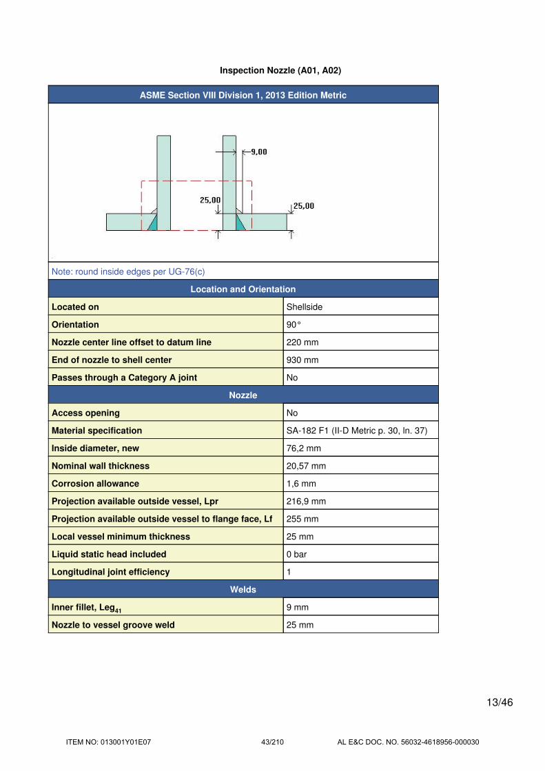
Inspection Nozzle (A01, A02)
ASME Section VIII Division 1, 2013 Edition Metric
Note: round inside edges per UG-76(c)
Location and Orientation
Located on Shellside
Orientation 90°
Nozzle center line offset to datum line 220 mm
End of nozzle to shell center 930 mm
Passes through a Category A joint No
Nozzle
Access opening No
Material specification SA-182 F1 (II-D Metric p. 30, ln. 37)
Inside diameter, new 76,2 mm
Nominal wall thickness 20,57 mm
Corrosion allowance 1,6 mm
Projection available outside vessel, Lpr 216,9 mm
Projection available outside vessel to flange face, Lf 255 mm
Local vessel minimum thickness 25 mm
Liquid static head included 0 bar
Longitudinal joint efficiency 1
Welds
Inner fillet, Leg41 9 mm
Nozzle to vessel groove weld 25 mm
13/46
ITEM NO: 013001Y01E07 43/210 AL E&C DOC. NO. 56032-4618956-000030

ASME B16.5-2009 Flange
Description NPS 3 Class 600 LWN A182 F1
Bolt Material SA-193 B7 Bolt <= 64 (II-D Metric p. 352, ln. 31)
Blind included Yes
Rated MDMT -48°C
Liquid static head 0 bar
MAWP rating 88,34 bar @ 260°C
MAP rating 96 bar @ 25°C
Hydrotest rating 145 bar @ 25°C
PWHT performed Yes
Impact Tested No
Gasket
Description Flexitallic Spiral Wound CGI 321 S.S.
Notes
Flange rated MDMT per UCS-66(b)(1)(b) = -48°C (Coincident ratio = 0,4375)
Bolts rated MDMT per Fig UCS-66 note (c) = -48°C
UCS-66 Material Toughness Requirements
LWN rated MDMT per UCS-66(c)(4) = -48°C
Material is exempt from impact testing at the Design MDMT of -5,4°C.
14/46
ITEM NO: 013001Y01E07 44/210 AL E&C DOC. NO. 56032-4618956-000030

Reinforcement Calculations for MAWP
Available reinforcement per UG-37 governs the MAWP of this nozzle.
UG-37 Area Calculation Summary (cm2)UG-45
Summary(mm)
For P = 48,06 bar @ 260 °C
The opening is adequately reinforced
The nozzle
passes UG-45
A
required
A
availableA1 A2 A3 A5
A
weldstreq tmin
17,7367 17,7374 1,4471 15,5348 -- -- 0,7555 7,33 20,57
UG-41 Weld Failure Path Analysis Summary
The nozzle is exempt from weld strength calculations per UW-15(b)(1)
UW-16 Weld Sizing Summary
Weld descriptionRequired weld
throat size (mm)
Actual weld
throat size (mm)Status
Nozzle to shell fillet (Leg41) 6 6,3 weld size is adequate
Calculations for internal pressure 48,06 bar @ 260 °C
Parallel Limit of reinforcement per UG-40
LR = MAX(d, Rn + (tn - Cn) + (t - C))
= MAX(79,4, 39,7 + (20,57 - 1,6) + (25 - 1,6))
= 82,07 mm
Outer Normal Limit of reinforcement per UG-40
LH = MIN(2,5*(t - C), 2,5*(tn - Cn) + te)
= MIN(2,5*(25 - 1,6), 2,5*(20,57 - 1,6) + 0)
= 47,44 mm
Nozzle required thickness per UG-27(c)(1)
trn = P*Rn / (Sn*E - 0,6*P)
= 48,0625*39,7 / (1.380*1 - 0,6*48,0625)
= 1,41 mm
Required thickness tr from UG-37(a)
tr = P*Ro / (S*E + 0,4*P)
= 48,0625*675 / (1.480*1 + 0,4*48,0625)
= 21,64 mm
15/46
ITEM NO: 013001Y01E07 45/210 AL E&C DOC. NO. 56032-4618956-000030

Area required per UG-37(c)
Allowable stresses: Sn = 1.407,207, Sv = 1.509,179 kgf/cm2
fr1 = lesser of 1 or Sn / Sv = 0,9324
fr2 = lesser of 1 or Sn / Sv = 0,9324
A = d*tr*F + 2*tn*tr*F*(1 - fr1)
= (79,4*21,64*1 + 2*18,97*21,64*1*(1 - 0,9324)) / 100
= 17,7367 cm2
Area available from FIG. UG-37.1
A1 = larger of the following= 1,4471 cm2
= d*(E1*t - F*tr) - 2*tn*(E1*t - F*tr)*(1 - fr1)
= (79,4*(1*23,4 - 1*21,64) - 2*18,97*(1*23,4 - 1*21,64)*(1 - 0,9324)) / 100
= 1,3529 cm2
= 2*(t + tn)*(E1*t - F*tr) - 2*tn*(E1*t - F*tr)*(1 - fr1)
= (2*(23,4 + 18,97)*(1*23,4 - 1*21,64) - 2*18,97*(1*23,4 - 1*21,64)*(1 - 0,9324)) / 100
= 1,4471 cm2
A2 = smaller of the following= 15,5348 cm2
= 5*(tn - trn)*fr2*t
= (5*(18,97 - 1,41)*0,9324*23,4) / 100
= 19,158 cm2
= 5*(tn - trn)*fr2*tn= (5*(18,97 - 1,41)*0,9324*18,97) / 100
= 15,5348 cm2
A41 = Leg2*fr2= (92*0,9324) / 100
= 0,7555 cm2
Area = A1 + A2 + A41
= 1,4471 + 15,5348 + 0,7555
= 17,7374 cm2
As Area >= A the reinforcement is adequate.
16/46
ITEM NO: 013001Y01E07 46/210 AL E&C DOC. NO. 56032-4618956-000030

UW-16(c) Weld Check
Fillet weld: tmin = lesser of 19 mm or tn or t = 18,97 mm
tc(min) = lesser of 6 mm or 0,7*tmin = 6 mm
tc(actual) = 0,7*Leg = 0.7*9 = 6,3 mm
The fillet weld size is satisfactory.
Weld strength calculations are not required for this detail which conforms to Fig. UW-16.1, sketch (c-e).
UG-45 Nozzle Neck Thickness Check
ta UG-27 = P*Rn / (Sn*E - 0,6*P) + Corrosion
= 48,0625*39,7 / (1.380*1 - 0,6*48,0625) + 1,6
= 3,01 mm
ta = max[ ta UG-27 , ta UG-22 ]
= max[ 3,01 , 0 ]
= 3,01 mm
tb1 = P*Ro / (S*E + 0,4*P) + Corrosion
= 48,0625*675 / (1.480*1 + 0,4*48,0625) + 1,6
= 23,24 mm
tb1 = max[ tb1 , tb UG16 ]
= max[ 23,24 , 3,1 ]
= 23,24 mm
tb = min[ tb3 , tb1 ]
= min[ 7,33 , 23,24 ]
= 7,33 mm
tUG-45 = max[ ta , tb ]
= max[ 3,01 , 7,33 ]
= 7,33 mm
Available nozzle wall thickness new, tn = 20,57 mm
The nozzle neck thickness is adequate.
17/46
ITEM NO: 013001Y01E07 47/210 AL E&C DOC. NO. 56032-4618956-000030

Reinforcement Calculations for MAP
Available reinforcement per UG-37 governs the MAP of this nozzle.
UG-37 Area Calculation Summary (cm2)UG-45
Summary(mm)
For P = 54,64 bar @ 25 °C
The opening is adequately reinforced
The nozzle
passes UG-45
A
required
A
availableA1 A2 A3 A5
A
weldstreq tmin
19,3973 19,3974 0,3897 18,2522 -- -- 0,7555 5,73 20,57
UG-41 Weld Failure Path Analysis Summary
The nozzle is exempt from weld strength calculations per UW-15(b)(1)
UW-16 Weld Sizing Summary
Weld descriptionRequired weld
throat size (mm)
Actual weld
throat size (mm)Status
Nozzle to shell fillet (Leg41) 6 6,3 weld size is adequate
Calculations for internal pressure 54,64 bar @ 25 °C
Parallel Limit of reinforcement per UG-40
LR = MAX(d, Rn + (tn - Cn) + (t - C))
= MAX(76,2, 38,1 + (20,57 - 0) + (25 - 0))
= 83,67 mm
Outer Normal Limit of reinforcement per UG-40
LH = MIN(2,5*(t - C), 2,5*(tn - Cn) + te)
= MIN(2,5*(25 - 0), 2,5*(20,57 - 0) + 0)
= 51,44 mm
Nozzle required thickness per UG-27(c)(1)
trn = P*Rn / (Sn*E - 0,6*P)
= 54,6436*38,1 / (1.380*1 - 0,6*54,6436)
= 1,54 mm
Required thickness tr from UG-37(a)
tr = P*Ro / (S*E + 0,4*P)
= 54,6436*675 / (1.480*1 + 0,4*54,6436)
= 24,56 mm
18/46
ITEM NO: 013001Y01E07 48/210 AL E&C DOC. NO. 56032-4618956-000030

Area required per UG-37(c)
Allowable stresses: Sn = 1.407,207, Sv = 1.509,179 kgf/cm2
fr1 = lesser of 1 or Sn / Sv = 0,9324
fr2 = lesser of 1 or Sn / Sv = 0,9324
A = d*tr*F + 2*tn*tr*F*(1 - fr1)
= (76,2*24,56*1 + 2*20,57*24,56*1*(1 - 0,9324)) / 100
= 19,3973 cm2
Area available from FIG. UG-37.1
A1 = larger of the following= 0,3897 cm2
= d*(E1*t - F*tr) - 2*tn*(E1*t - F*tr)*(1 - fr1)
= (76,2*(1*25 - 1*24,56) - 2*20,57*(1*25 - 1*24,56)*(1 - 0,9324)) / 100
= 0,3239 cm2
= 2*(t + tn)*(E1*t - F*tr) - 2*tn*(E1*t - F*tr)*(1 - fr1)
= (2*(25 + 20,57)*(1*25 - 1*24,56) - 2*20,57*(1*25 - 1*24,56)*(1 - 0,9324)) / 100
= 0,3897 cm2
A2 = smaller of the following= 18,2522 cm2
= 5*(tn - trn)*fr2*t
= (5*(20,57 - 1,54)*0,9324*25) / 100
= 22,1793 cm2
= 5*(tn - trn)*fr2*tn= (5*(20,57 - 1,54)*0,9324*20,57) / 100
= 18,2522 cm2
A41 = Leg2*fr2= (92*0,9324) / 100
= 0,7555 cm2
Area = A1 + A2 + A41
= 0,3897 + 18,2522 + 0,7555
= 19,3974 cm2
As Area >= A the reinforcement is adequate.
19/46
ITEM NO: 013001Y01E07 49/210 AL E&C DOC. NO. 56032-4618956-000030

UW-16(c) Weld Check
Fillet weld: tmin = lesser of 19 mm or tn or t = 19 mm
tc(min) = lesser of 6 mm or 0,7*tmin = 6 mm
tc(actual) = 0,7*Leg = 0.7*9 = 6,3 mm
The fillet weld size is satisfactory.
Weld strength calculations are not required for this detail which conforms to Fig. UW-16.1, sketch (c-e).
UG-45 Nozzle Neck Thickness Check
ta UG-27 = P*Rn / (Sn*E - 0,6*P) + Corrosion
= 54,6436*38,1 / (1.380*1 - 0,6*54,6436) + 0
= 1,54 mm
ta = max[ ta UG-27 , ta UG-22 ]
= max[ 1,54 , 0 ]
= 1,54 mm
tb1 = P*Ro / (S*E + 0,4*P) + Corrosion
= 54,6436*675 / (1.480*1 + 0,4*54,6436) + 0
= 24,56 mm
tb1 = max[ tb1 , tb UG16 ]
= max[ 24,56 , 1,5 ]
= 24,56 mm
tb = min[ tb3 , tb1 ]
= min[ 5,73 , 24,56 ]
= 5,73 mm
tUG-45 = max[ ta , tb ]
= max[ 1,54 , 5,73 ]
= 5,73 mm
Available nozzle wall thickness new, tn = 20,57 mm
The nozzle neck thickness is adequate.
20/46
ITEM NO: 013001Y01E07 50/210 AL E&C DOC. NO. 56032-4618956-000030

Reinforcement Calculations for External Pressure
UG-37 Area Calculation Summary(cm2)
UG-45Summary
(mm)
For Pe = 1 bar @ 260 °CThe nozzle
passes UG-45
A
required
A
availableA1 A2 A3 A5
A
weldstreq tmin
This nozzle is exempt from area
calculations per UG-36(c)(3)(a)3,1 20,57
UG-41 Weld Failure Path Analysis Summary
Weld strength calculations are not required for external pressure
UW-16 Weld Sizing Summary
Weld descriptionRequired weld
throat size (mm)
Actual weld
throat size (mm)Status
Nozzle to shell fillet (Leg41) 6 6,3 weld size is adequate
Calculations for external pressure 1 bar @ 260 °C
Parallel Limit of reinforcement per UG-40
LR = MAX(d, Rn + (tn - Cn) + (t - C))
= MAX(79,4, 39,7 + (20,57 - 1,6) + (25 - 1,6))
= 82,07 mm
Outer Normal Limit of reinforcement per UG-40
LH = MIN(2,5*(t - C), 2,5*(tn - Cn) + te)
= MIN(2,5*(25 - 1,6), 2,5*(20,57 - 1,6) + 0)
= 47,44 mm
Nozzle required thickness per UG-28 trn = 0,53 mm
From UG-37(d)(1) required thickness tr = 8,52 mm
This opening does not require reinforcement per UG-36(c)(3)(a)
UW-16(c) Weld Check
Fillet weld: tmin = lesser of 19 mm or tn or t = 18,97 mm
tc(min) = lesser of 6 mm or 0,7*tmin = 6 mm
tc(actual) = 0,7*Leg = 0.7*9 = 6,3 mm
21/46
ITEM NO: 013001Y01E07 51/210 AL E&C DOC. NO. 56032-4618956-000030

The fillet weld size is satisfactory.
Weld strength calculations are not required for this detail which conforms to Fig. UW-16.1, sketch (c-e).
UG-45 Nozzle Neck Thickness Check
ta UG-28 = 2,13 mm
ta = max[ ta UG-28 , ta UG-22 ]
= max[ 2,13 , 0 ]
= 2,13 mm
tb2 = P*Ro / (S*E + 0,4*P) + Corrosion
= 1*675 / (1.480*1 + 0,4*1) + 1,6
= 2,06 mm
tb2 = max[ tb2 , tb UG16 ]
= max[ 2,06 , 3,1 ]
= 3,1 mm
tb = min[ tb3 , tb2 ]
= min[ 7,33 , 3,1 ]
= 3,1 mm
tUG-45 = max[ ta , tb ]
= max[ 2,13 , 3,1 ]
= 3,1 mm
Available nozzle wall thickness new, tn = 20,57 mm
The nozzle neck thickness is adequate.
External Pressure, (Corroded & at 260 °C) UG-28(c)
L / Do = 257,55 / 117,35 = 2,1948
Do / t = 117,35 / 0,53 = 220,4728
From table G: A = 0,000182
From table CS-2 Metric: B = 168,6104 kg/cm2 (165,35 bar)
Pa = 4*B / (3*(Do / t))
= 4*165,35 / (3*(117,35 / 0,53))
= 1 bar
Design thickness for external pressure Pa = 1 bar
ta = t + Corrosion = 0,53 + 1,6 = 2,13 mm
22/46
ITEM NO: 013001Y01E07 52/210 AL E&C DOC. NO. 56032-4618956-000030

Riser / Downcomer (R01- 02, D01-02)
ASME Section VIII Division 1, 2013 Edition Metric
Note: Per UW-16(b) minimum inside corner radius r1 = min [1 / 4*t , 3 mm] = 3 mm
Location and Orientation
Located on Shellside
Orientation 0°
Nozzle center line offset to datum line 2.070 mm
End of nozzle to shell center 900 mm
Passes through a Category A joint No
Nozzle
Access opening No
Material specification SA-182 F1 (II-D Metric p. 30, ln. 37)
Inside diameter, new 242,8 mm
Wall thickness, tn 41,1 mm
Minimum wall thickness 15,1 mm
Corrosion allowance 1,6 mm
Projection available outside vessel, Lpr 225 mm
Heavy barrel length, Lhb 100 mm
Local vessel minimum thickness 25 mm
Liquid static head included 0 bar
Longitudinal joint efficiency 1
Welds
Inner fillet, Leg41 9 mm
Nozzle to vessel groove weld 25 mm
23/46
ITEM NO: 013001Y01E07 53/210 AL E&C DOC. NO. 56032-4618956-000030

UCS-66 Material Toughness Requirements Nozzle At Intersection
Governing thickness, tg = 25 mm
Exemption temperature from Fig UCS-66M Curve B = -1,5°C
tr = 42*675 / (1.480*1 + 0,4*42) = 18,94 mm
Stress ratio = tr*E* / (tn - c) = 18,94*1 / (25 - 1,6) = 0,8094
Reduction in MDMT, TR from Fig UCS-66.1M = 10,7°C
MDMT = max[ MDMT - TR, -48] = max[ -1,5 - 10,7 , -48] = -12,2°C
Material is exempt from impact testing at the Design MDMT of -5,4°C.
UCS-66 Material Toughness Requirements Nozzle
Governing thickness, tg = 15,1 mm
Exemption temperature from Fig UCS-66M Curve B = -16,5°C
External nozzle loadings per UG-22 govern the coincident ratio used.
Stress ratio = tr*E* / (tn - c) = 6,42*1 / (15,1 - 1,6) = 0,4754
Reduction in MDMT, TR from Fig UCS-66.1M = 34,7°C
MDMT = max[ MDMT - TR, -48] = max[ -16,5 - 34,7 , -48] = -48°C
Material is exempt from impact testing at the Design MDMT of -5,4°C.
24/46
ITEM NO: 013001Y01E07 54/210 AL E&C DOC. NO. 56032-4618956-000030

Reinforcement Calculations for MAWP
Available reinforcement per UG-37 governs the MAWP of this nozzle.
UG-37 Area Calculation Summary (cm2)UG-45
Summary(mm)
For P = 43,23 bar @ 260 °C
The opening is adequately reinforced
The nozzle
passes UG-45
A
required
A
availableA1 A2 A3 A5
A
weldstreq tmin
48,9784 48,9793 9,4168 38,807 -- -- 0,7555 9,71 15,1
UG-41 Weld Failure Path Analysis Summary
The nozzle is exempt from weld strength calculations per UW-15(b)(1)
UW-16 Weld Sizing Summary
Weld descriptionRequired weld
throat size (mm)
Actual weld
throat size (mm)Status
Nozzle to shell fillet (Leg41) 6 6,3 weld size is adequate
WRC 107
Load CaseP
(bar)
Pr
(kgf)
Mc
(kgf-m)
Vc
(kgf)
ML
(kgf-m)
VL
(kgf)
Mt
(kgf-m)
Max
Comb
Stress
(kgf/cm2)
Allow
Comb
Stress
(kgf/cm2)
Max
Local
Primary
Stress
(kgf/cm2)
Allow
Local
Primary
Stress
(kgf/cm2)
Over
stressed
Load case 1 43,23 1.580 3.950 0 2.300 0 0 3.789,401 4.527,536 1.842,603 2.263,768 No
Load case 1 (Hot Shut Down) 0 1.580 3.950 0 2.300 0 0 -2.869,928 4.527,536 -411,014 2.263,768 No
Calculations for internal pressure 43,23 bar @ 260 °C
Parallel Limit of reinforcement per UG-40 and Fig. UG-40 sketch (e-2)
LR = MAX(d, Rn + (tn - Cn) + (t - C))
= MAX(246, 123 + (41,1 - 1,6) + (25 - 1,6))
= 246 mm
Outer Normal Limit of reinforcement per UG-40 and Fig. UG-40 sketch (e-2)
LH = MIN(2,5*(t - C), 2,5*(tn - Cn) + te)
= MIN(2,5*(25 - 1,6), 2,5*(41,1 - 1,6) + 0)
= 58,5 mm
Nozzle required thickness per UG-27(c)(1)
trn = P*Rn / (Sn*E - 0,6*P)
= 43,2258*123 / (1.380*1 - 0,6*43,2258)
= 3,93 mm
25/46
ITEM NO: 013001Y01E07 55/210 AL E&C DOC. NO. 56032-4618956-000030

Required thickness tr from UG-37(a)
tr = P*Ro / (S*E + 0,4*P)
= 43,2258*675 / (1.480*1 + 0,4*43,2258)
= 19,49 mm
Area required per UG-37(c)
Allowable stresses: Sn = 1.407,207, Sv = 1.509,179 kgf/cm2
fr1 = lesser of 1 or Sn / Sv = 0,9324
fr2 = lesser of 1 or Sn / Sv = 0,9324
A = d*tr*F + 2*tn*tr*F*(1 - fr1)
= (246*19,49*1 + 2*39,5*19,49*1*(1 - 0,9324)) / 100
= 48,9784 cm2
Area available from FIG. UG-37.1
A1 = larger of the following= 9,4168 cm2
= d*(E1*t - F*tr) - 2*tn*(E1*t - F*tr)*(1 - fr1)
= (246*(1*23,4 - 1*19,49) - 2*39,5*(1*23,4 - 1*19,49)*(1 - 0,9324)) / 100
= 9,4168 cm2
= 2*(t + tn)*(E1*t - F*tr) - 2*tn*(E1*t - F*tr)*(1 - fr1)
= (2*(23,4 + 39,5)*(1*23,4 - 1*19,49) - 2*39,5*(1*23,4 - 1*19,49)*(1 - 0,9324)) / 100
= 4,7135 cm2
A2 = smaller of the following= 38,807 cm2
= 5*(tn - trn)*fr2*t
= (5*(39,5 - 3,93)*0,9324*23,4) / 100
= 38,807 cm2
= 5*(tn - trn)*fr2*tn= (5*(39,5 - 3,93)*0,9324*39,5) / 100
= 65,5076 cm2
A41 = Leg2*fr2= (92*0,9324) / 100
= 0,7555 cm2
Area = A1 + A2 + A41
= 9,4168 + 38,807 + 0,7555
26/46
ITEM NO: 013001Y01E07 56/210 AL E&C DOC. NO. 56032-4618956-000030

= 48,9793 cm2
As Area >= A the reinforcement is adequate.
UW-16(c) Weld Check
Fillet weld: tmin = lesser of 19 mm or tn or t = 19 mm
tc(min) = lesser of 6 mm or 0,7*tmin = 6 mm
tc(actual) = 0,7*Leg = 0.7*9 = 6,3 mm
The fillet weld size is satisfactory.
Weld strength calculations are not required for this detail which conforms to Fig. UW-16.1, sketch (c-e).
UG-45 Nozzle Neck Thickness Check
ta UG-27 = P*Rn / (Sn*E - 0,6*P) + Corrosion
= 43,2258*123 / (1.380*1 - 0,6*43,2258) + 1,6
= 5,53 mm
ta UG-22 = 8,09 mm
ta = max[ ta UG-27 , ta UG-22 ]
= max[ 5,53 , 8,09 ]
= 8,09 mm
tb1 = P*Ro / (S*E + 0,4*P) + Corrosion
= 43,2258*675 / (1.480*1 + 0,4*43,2258) + 1,6
= 21,09 mm
tb1 = max[ tb1 , tb UG16 ]
= max[ 21,09 , 3,1 ]
= 21,09 mm
tb = min[ tb3 , tb1 ]
= min[ 9,71 , 21,09 ]
= 9,71 mm
tUG-45 = max[ ta , tb ]
= max[ 8,09 , 9,71 ]
= 9,71 mm
Available nozzle wall thickness new, tn = 15,1 mm
The nozzle neck thickness is adequate.
27/46
ITEM NO: 013001Y01E07 57/210 AL E&C DOC. NO. 56032-4618956-000030

WRC 107 Load case 1
Applied Loads
Radial load, Pr 1.580 kgf
Circumferential moment, Mc 3.950 kgf-m
Circumferential shear, Vc 0 kgf
Longitudinal moment, ML 2.300 kgf-m
Longitudinal shear, VL 0 kgf
Torsion moment, Mt 0 kgf-m
Internal pressure, P 43,23 bar
Mean shell radius, Rm 663,3 mm
Local shell thickness, T 23,4 mm
Design factor 3
Maximum stresses due to the applied loads at the nozzle OD (includes pressure)
γ = Rm / T = 663,3 / 23,4 = 28,3464
β = 0,875*ro / Rm = 0,875*162,5 / 663,3 = 0,2144
Pressure stress intensity factor, I = 1,2736 (derived from Division 2 Part 4.5)
Local circumferential pressure stress = I*P*Ri / T =1.563,204 kgf/cm2
Local longitudinal pressure stress = I*P*Ri / (2*T) =781,602 kgf/cm2
Maximum combined stress (PL+P
b+Q) = 3.789,4 kgf/cm2
Allowable combined stress (PL+P
b+Q) = ±3*S = ±4.527,54 kgf/cm2
The maximum combined stress (PL+P
b+Q) is within allowable limits.
Maximum local primary membrane stress (PL) = 1.842,6 kgf/cm2
Allowable local primary membrane stress (PL) = ±1,5*S = ±2.263,77 kgf/cm2
The maximum local primary membrane stress (PL) is within allowable limits.
28/46
ITEM NO: 013001Y01E07 58/210 AL E&C DOC. NO. 56032-4618956-000030

Stresses at the nozzle OD per WRC Bulletin 107
Figure value Au Al Bu Bl Cu Cl Du Dl
3C* Nφ / (P / Rm) 2,7305 0 0 0 0 -27,771 -27,771 -27,771 -27,771
4C* Nφ / (P / Rm) 4,0369 -41,13 -41,13 -41,13 -41,13 0 0 0 0
1C Mφ / P 0,0729 0 0 0 0 -126,201 126,201 -126,201 126,201
2C-1 Mφ / P 0,0413 -71,502 71,502 -71,502 71,502 0 0 0 0
3A* Nφ / [Mc / (Rm2*β)] 1,1768 0 0 0 0 -210,639 -210,639 210,639 210,639
1A Mφ / [Mc / (Rm*β)] 0,0823 0 0 0 0 -2.505,316 2.505,316 2.505,316 -2.505,316
3B* Nφ / [ML / (Rm2*β)] 3,0757 -320,529 -320,529 320,529 320,529 0 0 0 0
1B-1 Mφ / [ML / (Rm*β)] 0,0294 -521,115 521,115 521,115 -521,115 0 0 0 0
Pressure stress* 1.563,204 1.563,204 1.563,204 1.563,204 1.227,418 1.227,418 1.227,418 1.227,418
Total circumferential stress 608,928 1.794,162 2.292,216 1.392,991 -1.642,51 3.620,524 3.789,401 -968,829
Primary membrane circumferential
stress*1.201,545 1.201,545 1.842,603 1.842,603 989,007 989,007 1.410,286 1.410,286
3C* Nx / (P / Rm) 2,7305 -27,771 -27,771 -27,771 -27,771 0 0 0 0
4C* Nx / (P / Rm) 4,0369 0 0 0 0 -41,13 -41,13 -41,13 -41,13
1C-1 Mx / P 0,0777 -134,497 134,497 -134,497 134,497 0 0 0 0
2C Mx / P 0,0421 0 0 0 0 -72,908 72,908 -72,908 72,908
4A* Nx / [Mc / (Rm2*β)] 2,0666 0 0 0 0 -369,885 -369,885 369,885 369,885
2A Mx / [Mc / (Rm*β)] 0,0429 0 0 0 0 -1.305,951 1.305,951 1.305,951 -1.305,951
4B* Nx / [ML / (Rm2*β)] 1,1435 -119,17 -119,17 119,17 119,17 0 0 0 0
2B-1 Mx / [ML / (Rm*β)] 0,0479 -849,026 849,026 849,026 -849,026 0 0 0 0
Pressure stress* 613,709 613,709 613,709 613,709 781,602 781,602 781,602 781,602
Total longitudinal stress -516,756 1.450,291 1.419,637 -9,421 -1.008,271 1.749,447 2.343,399 -122,686
Primary membrane longitudinal stress* 466,768 466,768 705,108 705,108 370,588 370,588 1.110,357 1.110,357
Shear from Mt 0 0 0 0 0 0 0 0
Circ shear from Vc 0 0 0 0 0 0 0 0
Long shear from VL 0 0 0 0 0 0 0 0
Total Shear stress 0 0 0 0 0 0 0 0
Combined stress (PL+Pb+Q) -1.125,684 1.794,162 2.292,216 -1.402,412 -1.642,51 3.620,524 3.789,401 -968,829
* denotes primary stress.
Longitudinal stress in the nozzle wall due to internal pressure + external loads
σn (Pm) = P*Ri / (2*tn) - Pr / (π*(Ro2 - Ri
2)) + M*Ro / I
= 43,23*1,02*123 / (2*13,5) - 1.580 / (π*(136,52 - 1232))*100 + 4.570.813,1*136,5 / 9,2892E+07*100
= 858,101 kgf/cm2
The average primary stress Pm (see Division 2 5.6.a.1) across the nozzle wall due to internal pressure + external
loads is acceptable ( ≤ S = 1.407,207 kgf/cm2)
29/46
ITEM NO: 013001Y01E07 59/210 AL E&C DOC. NO. 56032-4618956-000030

Reinforcement Calculations for MAP
Available reinforcement per UG-37 governs the MAP of this nozzle.
UG-37 Area Calculation Summary (cm2)UG-45
Summary(mm)
For P = 47,12 bar @ 25 °C
The opening is adequately reinforced
The nozzle
passes UG-45
A
required
A
availableA1 A2 A3 A5
A
weldstreq tmin
52,6967 52,698 8,9722 42,9702 -- -- 0,7555 8,11 15,1
UG-41 Weld Failure Path Analysis Summary
The nozzle is exempt from weld strength calculations per UW-15(b)(1)
UW-16 Weld Sizing Summary
Weld descriptionRequired weld
throat size (mm)
Actual weld
throat size (mm)Status
Nozzle to shell fillet (Leg41) 6 6,3 weld size is adequate
Calculations for internal pressure 47,12 bar @ 25 °C
Parallel Limit of reinforcement per UG-40 and Fig. UG-40 sketch (e-1)
LR = MAX(d, Rn + (tn - Cn) + (t - C))
= MAX(242,8, 121,4 + (15,1 - 0) + (25 - 0))
= 242,8 mm
Outer Normal Limit of reinforcement per UG-40 and Fig. UG-40 sketch (e-1)
LH = MIN(2,5*(t - C), 2,5*(tn - Cn) + te)
= MIN(2,5*(25 - 0), 2,5*(15,1 - 0) + 45,03)
= 62,5 mm
te = MIN( 100 + 26*tan(30) , 26*tan(60) )
= 45,03 mm
Nozzle required thickness per UG-27(c)(1)
trn = P*Rn / (Sn*E - 0,6*P)
= 47,1153*121,4 / (1.380*1 - 0,6*47,1153)
= 4,23 mm
Required thickness tr from UG-37(a)
tr = P*Ro / (S*E + 0,4*P)
= 47,1153*675 / (1.480*1 + 0,4*47,1153)
30/46
ITEM NO: 013001Y01E07 60/210 AL E&C DOC. NO. 56032-4618956-000030

= 21,22 mm
Area required per UG-37(c)
Allowable stresses: Sn = 1.407,207, Sv = 1.509,179 kgf/cm2
fr1 = lesser of 1 or Sn / Sv = 0,9324
fr2 = lesser of 1 or Sn / Sv = 0,9324
A = d*tr*F + 2*tn*tr*F*(1 - fr1)
= (242,8*21,22*1 + 2*41,1*21,22*1*(1 - 0,9324)) / 100
= 52,6967 cm2
Area available from FIG. UG-37.1
A1 = larger of the following= 8,9722 cm2
= d*(E1*t - F*tr) - 2*tn*(E1*t - F*tr)*(1 - fr1)
= (242,8*(1*25 - 1*21,22) - 2*41,1*(1*25 - 1*21,22)*(1 - 0,9324)) / 100
= 8,9722 cm2
= 2*(t + tn)*(E1*t - F*tr) - 2*tn*(E1*t - F*tr)*(1 - fr1)
= (2*(25 + 41,1)*(1*25 - 1*21,22) - 2*41,1*(1*25 - 1*21,22)*(1 - 0,9324)) / 100
= 4,7897 cm2
A2 = smaller of the following= 42,9702 cm2
= 5*(tn - trn)*fr2*t
= (5*(41,1 - 4,23)*0,9324*25) / 100
= 42,9702 cm2
= 2*(tn - trn)*(2,5*tp + te)*fr2= (2*(41,1 - 4,23)*(2,5*15,1 + 45,03)*0,9324) / 100
= 56,916 cm2
A41 = Leg2*fr2= (92*0,9324) / 100
= 0,7555 cm2
Area = A1 + A2 + A41
= 8,9722 + 42,9702 + 0,7555
= 52,698 cm2
As Area >= A the reinforcement is adequate.
31/46
ITEM NO: 013001Y01E07 61/210 AL E&C DOC. NO. 56032-4618956-000030

UW-16(c) Weld Check
Fillet weld: tmin = lesser of 19 mm or tn or t = 19 mm
tc(min) = lesser of 6 mm or 0,7*tmin = 6 mm
tc(actual) = 0,7*Leg = 0.7*9 = 6,3 mm
The fillet weld size is satisfactory.
Weld strength calculations are not required for this detail which conforms to Fig. UW-16.1, sketch (c-e).
UG-45 Nozzle Neck Thickness Check
ta UG-27 = P*Rn / (Sn*E - 0,6*P) + Corrosion
= 47,1153*121,4 / (1.380*1 - 0,6*47,1153) + 0
= 4,23 mm
ta UG-22 = 6,71 mm
ta = max[ ta UG-27 , ta UG-22 ]
= max[ 4,23 , 6,71 ]
= 6,71 mm
tb1 = P*Ro / (S*E + 0,4*P) + Corrosion
= 47,1153*675 / (1.480*1 + 0,4*47,1153) + 0
= 21,22 mm
tb1 = max[ tb1 , tb UG16 ]
= max[ 21,22 , 1,5 ]
= 21,22 mm
tb = min[ tb3 , tb1 ]
= min[ 8,11 , 21,22 ]
= 8,11 mm
tUG-45 = max[ ta , tb ]
= max[ 6,71 , 8,11 ]
= 8,11 mm
Available nozzle wall thickness new, tn = 15,1 mm
The nozzle neck thickness is adequate.
32/46
ITEM NO: 013001Y01E07 62/210 AL E&C DOC. NO. 56032-4618956-000030
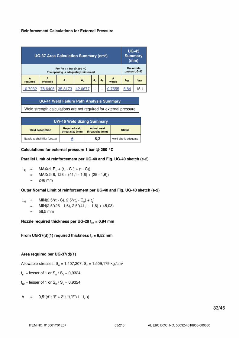
Reinforcement Calculations for External Pressure
UG-37 Area Calculation Summary (cm2)UG-45
Summary(mm)
For Pe = 1 bar @ 260 °C
The opening is adequately reinforced
The nozzle
passes UG-45
A
required
A
availableA1 A2 A3 A5
A
weldstreq tmin
10,7032 78,6405 35,8173 42,0677 -- -- 0,7555 5,84 15,1
UG-41 Weld Failure Path Analysis Summary
Weld strength calculations are not required for external pressure
UW-16 Weld Sizing Summary
Weld descriptionRequired weld
throat size (mm)
Actual weld
throat size (mm)Status
Nozzle to shell fillet (Leg41) 6 6,3 weld size is adequate
Calculations for external pressure 1 bar @ 260 °C
Parallel Limit of reinforcement per UG-40 and Fig. UG-40 sketch (e-2)
LR = MAX(d, Rn + (tn - Cn) + (t - C))
= MAX(246, 123 + (41,1 - 1,6) + (25 - 1,6))
= 246 mm
Outer Normal Limit of reinforcement per UG-40 and Fig. UG-40 sketch (e-2)
LH = MIN(2,5*(t - C), 2,5*(tn - Cn) + te)
= MIN(2,5*(25 - 1,6), 2,5*(41,1 - 1,6) + 45,03)
= 58,5 mm
Nozzle required thickness per UG-28 trn = 0,94 mm
From UG-37(d)(1) required thickness tr = 8,52 mm
Area required per UG-37(d)(1)
Allowable stresses: Sn = 1.407,207, Sv = 1.509,179 kgf/cm2
fr1 = lesser of 1 or Sn / Sv = 0,9324
fr2 = lesser of 1 or Sn / Sv = 0,9324
A = 0,5*(d*tr*F + 2*tn*tr*F*(1 - fr1))
33/46
ITEM NO: 013001Y01E07 63/210 AL E&C DOC. NO. 56032-4618956-000030

= (0,5*(246*8,52*1 + 2*39,5*8,52*1*(1 - 0,9324))) / 100
= 10,7032 cm2
Area available from FIG. UG-37.1
A1 = larger of the following= 35,8173 cm2
= d*(E1*t - F*tr) - 2*tn*(E1*t - F*tr)*(1 - fr1)
= (246*(1*23,4 - 1*8,52) - 2*39,5*(1*23,4 - 1*8,52)*(1 - 0,9324)) / 100
= 35,8173 cm2
= 2*(t + tn)*(E1*t - F*tr) - 2*tn*(E1*t - F*tr)*(1 - fr1)
= (2*(23,4 + 39,5)*(1*23,4 - 1*8,52) - 2*39,5*(1*23,4 - 1*8,52)*(1 - 0,9324)) / 100
= 17,9277 cm2
A2 = smaller of the following= 42,0677 cm2
= 5*(tn - trn)*fr2*t
= (5*(39,5 - 0,94)*0,9324*23,4) / 100
= 42,0677 cm2
= 5*(tn - trn)*fr2*tn= (5*(39,5 - 0,94)*0,9324*39,5) / 100
= 71,0121 cm2
A41 = Leg2*fr2= (92*0,9324) / 100
= 0,7555 cm2
Area = A1 + A2 + A41
= 35,8173 + 42,0677 + 0,7555
= 78,6405 cm2
As Area >= A the reinforcement is adequate.
UW-16(c) Weld Check
Fillet weld: tmin = lesser of 19 mm or tn or t = 19 mm
tc(min) = lesser of 6 mm or 0,7*tmin = 6 mm
tc(actual) = 0,7*Leg = 0.7*9 = 6,3 mm
The fillet weld size is satisfactory.
Weld strength calculations are not required for this detail which conforms to Fig. UW-16.1, sketch (c-e).
34/46
ITEM NO: 013001Y01E07 64/210 AL E&C DOC. NO. 56032-4618956-000030

UG-45 Nozzle Neck Thickness Check
ta UG-28 = 2,54 mm
ta UG-22 = 5,84 mm
ta = max[ ta UG-28 , ta UG-22 ]
= max[ 2,54 , 5,84 ]
= 5,84 mm
tb2 = P*Ro / (S*E + 0,4*P) + Corrosion
= 1*675 / (1.480*1 + 0,4*1) + 1,6
= 2,06 mm
tb2 = max[ tb2 , tb UG16 ]
= max[ 2,06 , 3,1 ]
= 3,1 mm
tb = min[ tb3 , tb2 ]
= min[ 9,71 , 3,1 ]
= 3,1 mm
tUG-45 = max[ ta , tb ]
= max[ 5,84 , 3,1 ]
= 5,84 mm
Available nozzle wall thickness new, tn = 15,1 mm
The nozzle neck thickness is adequate.
External Pressure, (Corroded & at 260 °C) UG-28(c)
L / Do = 244,85 / 325 = 0,7534
Do / t = 325 / 0,94 = 346,6448
From table G: A = 0,000285
From table CS-2 Metric: B = 265,1133 kg/cm2 (259,99 bar)
Pa = 4*B / (3*(Do / t))
= 4*259,99 / (3*(325 / 0,94))
= 1 bar
Design thickness for external pressure Pa = 1 bar
ta = t + Corrosion = 0,94 + 1,6 = 2,54 mm
35/46
ITEM NO: 013001Y01E07 65/210 AL E&C DOC. NO. 56032-4618956-000030

Blow Down Nozzle (N03, N04)
ASME Section VIII Division 1, 2013 Edition Metric
Note: round inside edges per UG-76(c)
Location and Orientation
Located on Shellside
Orientation 180°
Nozzle center line offset to datum line 2.120 mm
End of nozzle to shell center 930 mm
Passes through a Category A joint No
Nozzle
Access opening No
Material specification SA-182 F1 (II-D Metric p. 30, ln. 37)
Inside diameter, new 50,8 mm
Nominal wall thickness 16,64 mm
Corrosion allowance 1,6 mm
Projection available outside vessel, Lpr 223,25 mm
Projection available outside vessel to flange face, Lf 255 mm
Local vessel minimum thickness 25 mm
Liquid static head included 0 bar
Longitudinal joint efficiency 1
Welds
Inner fillet, Leg41 9 mm
Nozzle to vessel groove weld 25 mm
36/46
ITEM NO: 013001Y01E07 66/210 AL E&C DOC. NO. 56032-4618956-000030

ASME B16.5-2009 Flange
Description NPS 2 Class 600 LWN A182 F1
Bolt Material SA-193 B7 Bolt <= 64 (II-D Metric p. 352, ln. 31)
Blind included No
Rated MDMT -48°C
Liquid static head 0 bar
Consider External Loads on Flange MAWP Rating No
MAWP rating 88,34 bar @ 260°C
MAP rating 96 bar @ 25°C
Hydrotest rating 145 bar @ 25°C
PWHT performed Yes
Impact Tested No
Gasket
Description Flexitallic Spiral Wound CGI 321 S.S.
Notes
Flange rated MDMT per UCS-66(b)(1)(b) = -48°C (Coincident ratio = 0,4375)
Bolts rated MDMT per Fig UCS-66 note (c) = -48°C
UCS-66 Material Toughness Requirements
LWN rated MDMT per UCS-66(c)(4) = -48°C
Material is exempt from impact testing at the Design MDMT of -5,4°C.
37/46
ITEM NO: 013001Y01E07 67/210 AL E&C DOC. NO. 56032-4618956-000030

Reinforcement Calculations for MAWP
The vessel wall thickness governs the MAWP of this nozzle.
UG-37 Area Calculation Summary(cm2)
UG-45Summary
(mm)
For P = 52,03 bar @ 260 °CThe nozzle
passes UG-45
A
required
A
availableA1 A2 A3 A5
A
weldstreq tmin
This nozzle is exempt from area
calculations per UG-36(c)(3)(a)6,4 16,64
UG-41 Weld Failure Path Analysis Summary
The nozzle is exempt from weld strength calculations per UW-15(b)(2)
UW-16 Weld Sizing Summary
Weld descriptionRequired weld
throat size (mm)
Actual weld
throat size (mm)Status
Nozzle to shell fillet (Leg41) 6 6,3 weld size is adequate
WRC 107
Load CaseP
(bar)
Pr
(kgf)
Mc
(kgf-m)
Vc
(kgf)
ML
(kgf-m)
VL
(kgf)
Mt
(kgf-m)
Max
Comb
Stress
(kgf/cm2)
Allow
Comb
Stress
(kgf/cm2)
Max
Local
Primary
Stress
(kgf/cm2)
Allow
Local
Primary
Stress
(kgf/cm2)
Over
stressed
Load case 1 52,03 77 110 0 73 0 0 2.238,08 4.527,536 2.123,971 2.263,768 No
Load case 1 (Hot Shut Down) 0 77 110 0 73 0 0 -376,001 4.527,536 -21,233 2.263,768 No
Calculations for internal pressure 52,03 bar @ 260 °C
Parallel Limit of reinforcement per UG-40
LR = MAX(d, Rn + (tn - Cn) + (t - C))
= MAX(54, 27 + (16,64 - 1,6) + (25 - 1,6))
= 65,44 mm
Outer Normal Limit of reinforcement per UG-40
LH = MIN(2,5*(t - C), 2,5*(tn - Cn) + te)
= MIN(2,5*(25 - 1,6), 2,5*(16,64 - 1,6) + 0)
= 37,59 mm
Nozzle required thickness per UG-27(c)(1)
trn = P*Rn / (Sn*E - 0,6*P)
= 52,0273*27 / (1.380*1 - 0,6*52,0273)
= 1,04 mm
38/46
ITEM NO: 013001Y01E07 68/210 AL E&C DOC. NO. 56032-4618956-000030

Required thickness tr from UG-37(a)
tr = P*Ro / (S*E + 0,4*P)
= 52,0273*675 / (1.480*1 + 0,4*52,0273)
= 23,4 mm
This opening does not require reinforcement per UG-36(c)(3)(a)
UW-16(c) Weld Check
Fillet weld: tmin = lesser of 19 mm or tn or t = 15,04 mm
tc(min) = lesser of 6 mm or 0,7*tmin = 6 mm
tc(actual) = 0,7*Leg = 0.7*9 = 6,3 mm
The fillet weld size is satisfactory.
Weld strength calculations are not required for this detail which conforms to Fig. UW-16.1, sketch (c-e).
UG-45 Nozzle Neck Thickness Check
ta UG-27 = P*Rn / (Sn*E - 0,6*P) + Corrosion
= 52,0273*27 / (1.380*1 - 0,6*52,0273) + 1,6
= 2,64 mm
ta UG-22 = 4,18 mm
ta = max[ ta UG-27 , ta UG-22 ]
= max[ 2,64 , 4,18 ]
= 4,18 mm
tb1 = P*Ro / (S*E + 0,4*P) + Corrosion
= 52,0273*675 / (1.480*1 + 0,4*52,0273) + 1,6
= 25 mm
tb1 = max[ tb1 , tb UG16 ]
= max[ 25 , 3,1 ]
= 25 mm
tb = min[ tb3 , tb1 ]
= min[ 6,4 , 25 ]
= 6,4 mm
tUG-45 = max[ ta , tb ]
= max[ 4,18 , 6,4 ]
= 6,4 mm
Available nozzle wall thickness new, tn = 16,64 mm
39/46
ITEM NO: 013001Y01E07 69/210 AL E&C DOC. NO. 56032-4618956-000030

The nozzle neck thickness is adequate.
40/46
ITEM NO: 013001Y01E07 70/210 AL E&C DOC. NO. 56032-4618956-000030

WRC 107 Load case 1
Applied Loads
Radial load, Pr 77 kgf
Circumferential moment, Mc 110 kgf-m
Circumferential shear, Vc 0 kgf
Longitudinal moment, ML 73 kgf-m
Longitudinal shear, VL 0 kgf
Torsion moment, Mt 0 kgf-m
Internal pressure, P 52,03 bar
Mean shell radius, Rm 663,3 mm
Local shell thickness, T 23,4 mm
Design factor 3
Maximum stresses due to the applied loads at the nozzle OD (includes pressure)
γ = Rm / T = 663,3 / 23,4 = 28,3464
β = 0,875*ro / Rm = 0,875*42,04 / 663,3 = 0,0555
Pressure stress intensity factor, I = 1,4269 (derived from Division 2 Part 4.5)
Local circumferential pressure stress = I*P*Ri / T =2.108,082 kgf/cm2
Local longitudinal pressure stress = I*P*Ri / (2*T) =1.053,971 kgf/cm2
Maximum combined stress (PL+P
b+Q) = 2.238,08 kgf/cm2
Allowable combined stress (PL+P
b+Q) = ±3*S = ±4.527,54 kgf/cm2
The maximum combined stress (PL+P
b+Q) is within allowable limits.
Maximum local primary membrane stress (PL) = 2.123,97 kgf/cm2
Allowable local primary membrane stress (PL) = ±1,5*S = ±2.263,77 kgf/cm2
The maximum local primary membrane stress (PL) is within allowable limits.
41/46
ITEM NO: 013001Y01E07 71/210 AL E&C DOC. NO. 56032-4618956-000030

Stresses at the nozzle OD per WRC Bulletin 107
Figure value Au Al Bu Bl Cu Cl Du Dl
3C* Nφ / (P / Rm) 5,2958 0 0 0 0 -2,601 -2,601 -2,601 -2,601
4C* Nφ / (P / Rm) 5,4353 -2,672 -2,672 -2,672 -2,672 0 0 0 0
1C Mφ / P 0,1969 0 0 0 0 -16,592 16,592 -16,592 16,592
2C-1 Mφ / P 0,1585 -13,358 13,358 -13,358 13,358 0 0 0 0
3A* Nφ / [Mc / (Rm2*β)] 0,3711 0 0 0 0 -7,171 -7,171 7,171 7,171
1A Mφ / [Mc / (Rm*β)] 0,1067 0 0 0 0 -349,636 349,636 349,636 -349,636
3B* Nφ / [ML / (Rm2*β)] 1,4503 -18,561 -18,561 18,561 18,561 0 0 0 0
1B-1 Mφ / [ML / (Rm*β)] 0,0586 -127,466 127,466 127,466 -127,466 0 0 0 0
Pressure stress* 2.108,082 2.108,082 2.108,082 2.108,082 1.477,359 1.477,359 1.477,359 1.477,359
Total circumferential stress 1.946,025 2.227,674 2.238,08 2.009,863 1.101,358 1.833,815 1.814,973 1.148,885
Primary membrane circumferential
stress*2.086,849 2.086,849 2.123,971 2.123,971 1.467,586 1.467,586 1.481,929 1.481,929
3C* Nx / (P / Rm) 5,2958 -2,601 -2,601 -2,601 -2,601 0 0 0 0
4C* Nx / (P / Rm) 5,4353 0 0 0 0 -2,672 -2,672 -2,672 -2,672
1C-1 Mx / P 0,205 -17,296 17,296 -17,296 17,296 0 0 0 0
2C Mx / P 0,1581 0 0 0 0 -13,358 13,358 -13,358 13,358
4A* Nx / [Mc / (Rm2*β)] 0,4817 0 0 0 0 -9,281 -9,281 9,281 9,281
2A Mx / [Mc / (Rm*β)] 0,0624 0 0 0 0 -204,452 204,452 204,452 -204,452
4B* Nx / [ML / (Rm2*β)] 0,3666 -4,711 -4,711 4,711 4,711 0 0 0 0
2B-1 Mx / [ML / (Rm*β)] 0,0993 -215,983 215,983 215,983 -215,983 0 0 0 0
Pressure stress* 738,644 738,644 738,644 738,644 1.053,971 1.053,971 1.053,971 1.053,971
Total longitudinal stress 498,054 964,611 939,441 542,066 824,208 1.259,829 1.251,674 869,485
Primary membrane longitudinal stress* 731,332 731,332 740,754 740,754 1.042,019 1.042,019 1.060,58 1.060,58
Shear from Mt 0 0 0 0 0 0 0 0
Circ shear from Vc 0 0 0 0 0 0 0 0
Long shear from VL 0 0 0 0 0 0 0 0
Total Shear stress 0 0 0 0 0 0 0 0
Combined stress (PL+Pb+Q) 1.946,025 2.227,674 2.238,08 2.009,863 1.101,358 1.833,815 1.814,973 1.148,885
* denotes primary stress.
Longitudinal stress in the nozzle wall due to internal pressure + external loads
σn (Pm) = P*Ri / (2*tn) - Pr / (π*(Ro2 - Ri
2)) + M*Ro / I
= 52,03*1,02*27 / (2*15,04) - 77 / (π*(42,042 - 272))*100 + 132.018,4*42,04 / 2.035.151*100
= 317,96 kgf/cm2
The average primary stress Pm (see Division 2 5.6.a.1) across the nozzle wall due to internal pressure + external
loads is acceptable ( ≤ S = 1.407,207 kgf/cm2)
42/46
ITEM NO: 013001Y01E07 72/210 AL E&C DOC. NO. 56032-4618956-000030

Reinforcement Calculations for MAP
The vessel wall thickness governs the MAP of this nozzle.
UG-37 Area Calculation Summary(cm2)
UG-45Summary
(mm)
For P = 55,64 bar @ 25 °CThe nozzle
passes UG-45
A
required
A
availableA1 A2 A3 A5
A
weldstreq tmin
This nozzle is exempt from area
calculations per UG-36(c)(3)(a)4,8 16,64
UG-41 Weld Failure Path Analysis Summary
The nozzle is exempt from weld strength calculations per UW-15(b)(2)
UW-16 Weld Sizing Summary
Weld descriptionRequired weld
throat size (mm)
Actual weld
throat size (mm)Status
Nozzle to shell fillet (Leg41) 6 6,3 weld size is adequate
Calculations for internal pressure 55,64 bar @ 25 °C
Parallel Limit of reinforcement per UG-40
LR = MAX(d, Rn + (tn - Cn) + (t - C))
= MAX(50,8, 25,4 + (16,64 - 0) + (25 - 0))
= 67,04 mm
Outer Normal Limit of reinforcement per UG-40
LH = MIN(2,5*(t - C), 2,5*(tn - Cn) + te)
= MIN(2,5*(25 - 0), 2,5*(16,64 - 0) + 0)
= 41,59 mm
Nozzle required thickness per UG-27(c)(1)
trn = P*Rn / (Sn*E - 0,6*P)
= 55,639*25,4 / (1.380*1 - 0,6*55,639)
= 1,05 mm
Required thickness tr from UG-37(a)
tr = P*Ro / (S*E + 0,4*P)
= 55,639*675 / (1.480*1 + 0,4*55,639)
= 25 mm
This opening does not require reinforcement per UG-36(c)(3)(a)
43/46
ITEM NO: 013001Y01E07 73/210 AL E&C DOC. NO. 56032-4618956-000030

UW-16(c) Weld Check
Fillet weld: tmin = lesser of 19 mm or tn or t = 16,64 mm
tc(min) = lesser of 6 mm or 0,7*tmin = 6 mm
tc(actual) = 0,7*Leg = 0.7*9 = 6,3 mm
The fillet weld size is satisfactory.
Weld strength calculations are not required for this detail which conforms to Fig. UW-16.1, sketch (c-e).
UG-45 Nozzle Neck Thickness Check
ta UG-27 = P*Rn / (Sn*E - 0,6*P) + Corrosion
= 55,639*25,4 / (1.380*1 - 0,6*55,639) + 0
= 1,05 mm
ta UG-22 = 2,63 mm
ta = max[ ta UG-27 , ta UG-22 ]
= max[ 1,05 , 2,63 ]
= 2,63 mm
tb1 = P*Ro / (S*E + 0,4*P) + Corrosion
= 55,639*675 / (1.480*1 + 0,4*55,639) + 0
= 25 mm
tb1 = max[ tb1 , tb UG16 ]
= max[ 25 , 1,5 ]
= 25 mm
tb = min[ tb3 , tb1 ]
= min[ 4,8 , 25 ]
= 4,8 mm
tUG-45 = max[ ta , tb ]
= max[ 2,63 , 4,8 ]
= 4,8 mm
Available nozzle wall thickness new, tn = 16,64 mm
The nozzle neck thickness is adequate.
44/46
ITEM NO: 013001Y01E07 74/210 AL E&C DOC. NO. 56032-4618956-000030

Reinforcement Calculations for External Pressure
UG-37 Area Calculation Summary(cm2)
UG-45Summary
(mm)
For Pe = 1 bar @ 260 °CThe nozzle
passes UG-45
A
required
A
availableA1 A2 A3 A5
A
weldstreq tmin
This nozzle is exempt from area
calculations per UG-36(c)(3)(a)3,44 16,64
UG-41 Weld Failure Path Analysis Summary
Weld strength calculations are not required for external pressure
UW-16 Weld Sizing Summary
Weld descriptionRequired weld
throat size (mm)
Actual weld
throat size (mm)Status
Nozzle to shell fillet (Leg41) 6 6,3 weld size is adequate
Calculations for external pressure 1 bar @ 260 °C
Parallel Limit of reinforcement per UG-40
LR = MAX(d, Rn + (tn - Cn) + (t - C))
= MAX(54, 27 + (16,64 - 1,6) + (25 - 1,6))
= 65,44 mm
Outer Normal Limit of reinforcement per UG-40
LH = MIN(2,5*(t - C), 2,5*(tn - Cn) + te)
= MIN(2,5*(25 - 1,6), 2,5*(16,64 - 1,6) + 0)
= 37,59 mm
Nozzle required thickness per UG-28 trn = 0,44 mm
From UG-37(d)(1) required thickness tr = 8,52 mm
This opening does not require reinforcement per UG-36(c)(3)(a)
UW-16(c) Weld Check
Fillet weld: tmin = lesser of 19 mm or tn or t = 15,04 mm
tc(min) = lesser of 6 mm or 0,7*tmin = 6 mm
tc(actual) = 0,7*Leg = 0.7*9 = 6,3 mm
45/46
ITEM NO: 013001Y01E07 75/210 AL E&C DOC. NO. 56032-4618956-000030

The fillet weld size is satisfactory.
Weld strength calculations are not required for this detail which conforms to Fig. UW-16.1, sketch (c-e).
UG-45 Nozzle Neck Thickness Check
ta UG-28 = 2,04 mm
ta UG-22 = 3,44 mm
ta = max[ ta UG-28 , ta UG-22 ]
= max[ 2,04 , 3,44 ]
= 3,44 mm
tb2 = P*Ro / (S*E + 0,4*P) + Corrosion
= 1*675 / (1.480*1 + 0,4*1) + 1,6
= 2,06 mm
tb2 = max[ tb2 , tb UG16 ]
= max[ 2,06 , 3,1 ]
= 3,1 mm
tb = min[ tb3 , tb2 ]
= min[ 6,4 , 3,1 ]
= 3,1 mm
tUG-45 = max[ ta , tb ]
= max[ 3,44 , 3,1 ]
= 3,44 mm
Available nozzle wall thickness new, tn = 16,64 mm
The nozzle neck thickness is adequate.
External Pressure, (Corroded & at 260 °C) UG-28(c)
L / Do = 256,31 / 84,07 = 3,0486
Do / t = 84,07 / 0,44 = 191,8449
From table G: A = 0,000159
From table CS-2 Metric: B = 146,7188 kg/cm2 (143,88 bar)
Pa = 4*B / (3*(Do / t))
= 4*143,88 / (3*(84,07 / 0,44))
= 1 bar
Design thickness for external pressure Pa = 1 bar
ta = t + Corrosion = 0,44 + 1,6 = 2,04 mm
46/46
ITEM NO: 013001Y01E07 76/210 AL E&C DOC. NO. 56032-4618956-000030

BERTSCHenergy G m b H & Co KG
Herrengasse 23, 6700 Bludenz, Austria
www.bertsch.at
COMPRESS Pressure Vessel Design Calculations
Item: Process Gas Boiler
Vessel No: Tubeside
Customer: Air Liquide Global E&C Solutions SHANGHAI
Contract: 4618956-000SIN
Designer: Pirker
Date: 19.01.2017
ITEM NO: 013001Y01E07 77/210 AL E&C DOC. NO. 56032-4618956-000030
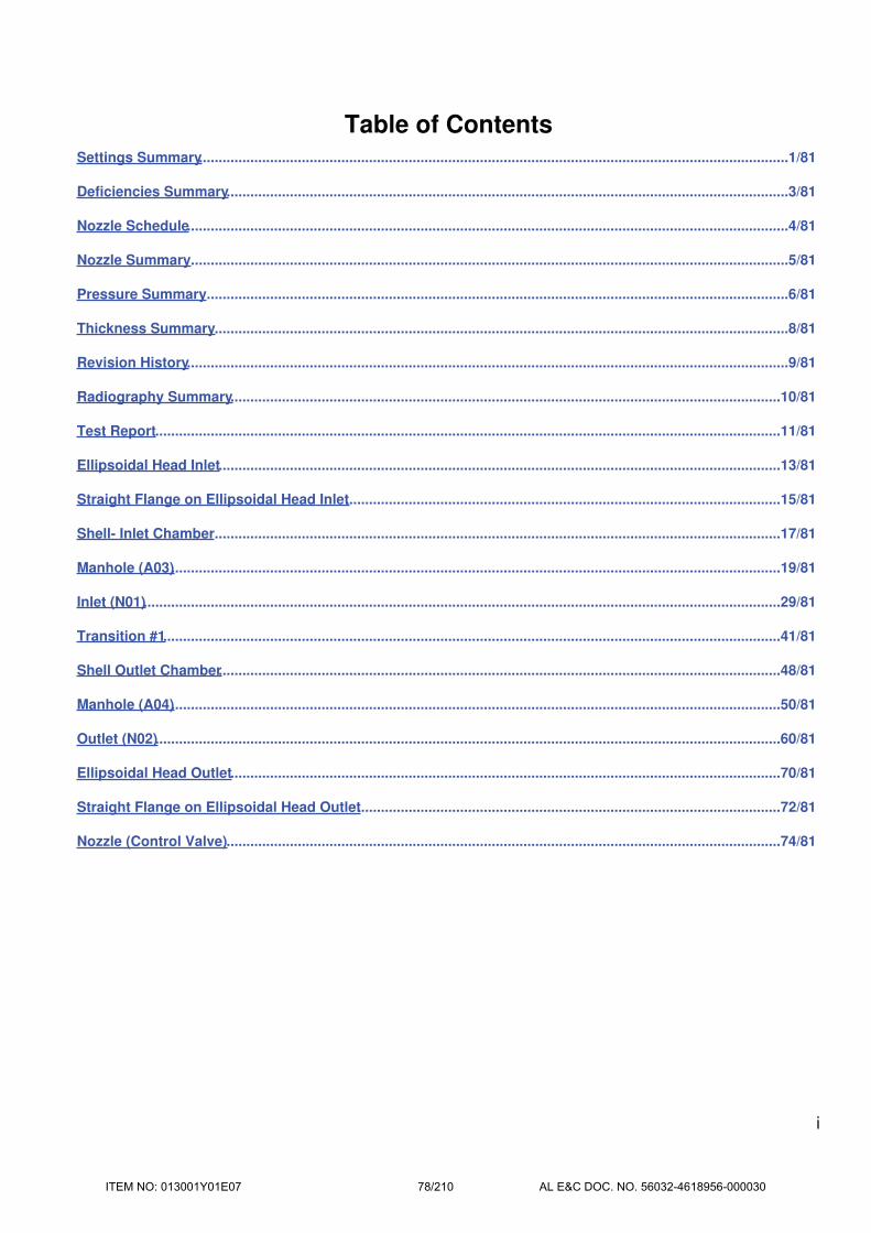
Table of ContentsSettings Summary.....................................................................................................................................................1/81
Deficiencies Summary..............................................................................................................................................3/81
Nozzle Schedule........................................................................................................................................................4/81
Nozzle Summary.......................................................................................................................................................5/81
Pressure Summary...................................................................................................................................................6/81
Thickness Summary.................................................................................................................................................8/81
Revision History........................................................................................................................................................9/81
Radiography Summary...........................................................................................................................................10/81
Test Report..............................................................................................................................................................11/81
Ellipsoidal Head Inlet..............................................................................................................................................13/81
Straight Flange on Ellipsoidal Head Inlet..............................................................................................................15/81
Shell- Inlet Chamber...............................................................................................................................................17/81
Manhole (A03)..........................................................................................................................................................19/81
Inlet (N01).................................................................................................................................................................29/81
Transition #1............................................................................................................................................................41/81
Shell Outlet Chamber..............................................................................................................................................48/81
Manhole (A04)..........................................................................................................................................................50/81
Outlet (N02)..............................................................................................................................................................60/81
Ellipsoidal Head Outlet...........................................................................................................................................70/81
Straight Flange on Ellipsoidal Head Outlet...........................................................................................................72/81
Nozzle (Control Valve)............................................................................................................................................74/81
i
ITEM NO: 013001Y01E07 78/210 AL E&C DOC. NO. 56032-4618956-000030

Settings Summary
COMPRESS 2017 Build 7700
ASME Section VIII Division 1, 2013 Edition Metric
Units MKS
Datum Line Location 0,00 mm from left seam
Vessel Design Mode Design Mode
Minimum thickness 1,5 mm per UG-16(b)
Design for cold shut down only No
Design for lethal service (full radiography required) No
User has limited MAWP to 30 bar
Design nozzles for Design P only
Corrosion weight loss 100% of theoretical loss
UG-23 Stress Increase 1,20
Skirt/legs stress increase 1,0
Minimum nozzle projection 152,4 mm
Juncture calculations for α > 30 only Yes
Preheat P-No 1 Materials > 1,25" and <= 1,50" thick Yes
UG-37(a) shell tr calculation considers longitudinal stress No
Cylindrical shells made from pipe are entered as minimum thickness No
Nozzles made from pipe are entered as minimum thickness No
ASME B16.9 fittings are entered as minimum thickness No
Butt weldsTapered per Figure
UCS-66.3(a)
Disallow Appendix 1-5, 1-8 calculations under 15 psi No
Hydro/Pneumatic Test
Shop Hydrotest at user defined pressure 41,35 bar
Test liquid specific gravity 1,00
Field Hydrotest at user defined pressure 41,35 bar
Wind load present @ field 33% of design
Maximum stress during test 90% of yield
Required Marking - UG-116
UG-116(e) Radiography RT1
UG-116(f) Postweld heat treatment HT
Code Cases\Interpretations
Use Code Case 2547 No
1/81
ITEM NO: 013001Y01E07 79/210 AL E&C DOC. NO. 56032-4618956-000030

Use Code Case 2695 No
Apply interpretation VIII-1-83-66 Yes
Apply interpretation VIII-1-86-175 Yes
Apply interpretation VIII-1-01-37 Yes
Apply interpretation VIII-1-01-150 Yes
Apply interpretation VIII-1-07-50 Yes
No UCS-66.1 MDMT reduction No
No UCS-68(c) MDMT reduction No
Disallow UG-20(f) exemptions No
UG-22 Loadings
UG-22(a) Internal or External Design Pressure Yes
UG-22(b) Weight of the vessel and normal contents under operating or test
conditionsNo
UG-22(c) Superimposed static reactions from weight of attached equipment
(external loads)No
UG-22(d)(2) Vessel supports such as lugs, rings, skirts, saddles and legs No
UG-22(f) Wind reactions No
UG-22(f) Seismic reactions No
UG-22(j) Test pressure and coincident static head acting during the test: No
Note: UG-22(b),(c) and (f) loads only considered when supports are present.
License Information
Company Name Bertsch Energy GmbH & Co KG
License Commercial
License Key ID 20080
Support Expires J� nner 24, 2018
2/81
ITEM NO: 013001Y01E07 80/210 AL E&C DOC. NO. 56032-4618956-000030

Deficiencies Summary
No deficiencies found.
3/81
ITEM NO: 013001Y01E07 81/210 AL E&C DOC. NO. 56032-4618956-000030

Nozzle Schedule
Specifications
Nozzle
markIdentifier Size Materials
Impact
TestedNormalized Fine Grain Flange Blind
A03 Manhole 881,13 OD x 54 Nozzle SA-182 F11 2 Yes Yes NoApp 2 Weld Neck Integral
SA-182 F11 2SA-182 F11 2
A04 Manhole 701,7 OD x 50 Nozzle SA-182 F11 2 Yes Yes NoApp 2 Weld Neck Integral
SA-182 F11 2SA-182 F11 2
Control Valve Nozzle 320 OD x 75 Nozzle SA-182 F11 2 Yes Yes No N/A No
N01 Inlet 996 OD x 50 Nozzle SA-387 11 2 Yes Yes No N/A No
N02 Outlet 374,65 OD x 34,92 Nozzle SA-182 F11 2 Yes Yes NoNPS 12 Class 300
LWN A182 F11 Cl.2 NNo
4/81
ITEM NO: 013001Y01E07 82/210 AL E&C DOC. NO. 56032-4618956-000030
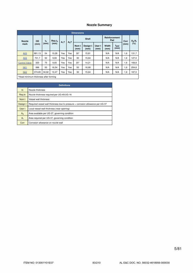
Nozzle Summary
Dimensions
Nozzle
mark
OD
(mm)
tn(mm)
Req tn(mm)
A1? A2?
ShellReinforcement
Pad Corr
(mm)
Aa/Ar
(%)Nom t
(mm)
Design t
(mm)
User t
(mm)
Width
(mm)
tpad
(mm)
A03 881,13 54 10,28 Yes Yes 30* 15,81 N/A N/A 1,6 131,7
A04 701,7 50 9,93 Yes Yes 30 15,64 N/A N/A 1,6 127,0
Control Valve 320 75 9,93 Yes Yes 20* 14,21 N/A N/A 1,6 169,8
N01 996 50 16,54 Yes Yes 50 16,68 N/A N/A 1,6 254,8
N02 374,65 34,92 10,47 Yes Yes 30 15,64 N/A N/A 1,6 187,0
*Head minimum thickness after forming
Definitions
tn Nozzle thickness
Req tn Nozzle thickness required per UG-45/UG-16
Nom t Vessel wall thickness
Design t Required vessel wall thickness due to pressure + corrosion allowance per UG-37
User t Local vessel wall thickness (near opening)
Aa Area available per UG-37, governing condition
Ar Area required per UG-37, governing condition
Corr Corrosion allowance on nozzle wall
5/81
ITEM NO: 013001Y01E07 83/210 AL E&C DOC. NO. 56032-4618956-000030

Pressure Summary
Component Summary
Identifier
P
Design
(bar)
T
Design
(°C)
MAWP
(bar)
MAP
(bar)
MDMT
(°C)
MDMT
Exemption
Impact
Tested
Ellipsoidal Head Inlet 30 400 59,85 63,16 -50,9 Note 1 Yes
Straight Flange on Ellipsoidal Head Inlet 30 400 58,49 61,84 -50,9 Note 2 Yes
Shell- Inlet Chamber 30 400 98,04 101,37 -105 Note 3 Yes
Transition #1 30 450 45,08 49,9 -40,2 Note 4 Yes
Shell Outlet Chamber 30 450 61,2 66,97 -54,3 Note 5 Yes
Straight Flange on Ellipsoidal Head Outlet 30 450 39,41 44,38 -34,7 Note 7 Yes
Ellipsoidal Head Outlet 30 450 40,09 45,05 -34,7 Note 6 Yes
Manhole (A03) 30 400 34,64 36,56 -48 Note 8 Yes
Manhole A03 30 450 30,28 35,1 -28,1 Note 9 Yes
Manhole A03 - Flange Hub 30 450 162,34 177,87 -105 Note 10 Yes
Bolted Cover for A03 30 450 32,65 35,81 -27,5 Note 11 Yes
Manhole (A04) 30 450 34,51 37,99 -54,3 Note 12 Yes
Manhole A04 30 450 47,62 53,46 -30 Note 13 Yes
Manhole A04 - Flange Hub 30 450 189,81 208,55 -105 Note 14 Yes
Bolted Cover A04 30 450 34,64 38,29 -30,3 Note 15 Yes
Nozzle (Control Valve) 30 450 43,95 49,37 -38,9 Note 16 Yes
Inlet (N01) 30 400 34,33 56,29 -40,2 Note 17 Yes
Outlet (N02) 30 450 33,7 48,11 -44,6 Note 18 Yes
Chamber Summary
Design MDMT -5,4 °C
Rated MDMT -27,5 °C @ 30,28 bar
MAWP hot & corroded 30 bar @ 400 °C
MAP cold & new 35,1 bar @ 20 °C
(1) The MAWP is limited due to the MAWP limit
set in the Calculations tab of the Set Mode
dialog.
(2) This pressure chamber is not designed for
external pressure.
6/81
ITEM NO: 013001Y01E07 84/210 AL E&C DOC. NO. 56032-4618956-000030

Notes for MDMT Rating
Note # Exemption Details
1. Straight Flange governs MDMT
2. Material is impact tested per UG-84 to -20°C. UCS-66(i) reduction of 30,9°C applied (ratio = 0,5069).
3. Material is impact tested per UG-84 to -20°C. Stress ratio = 0,3116 ≤ 0,35, MDMT per UCS-66(b)(3) = -105°C.
4. Material is impact tested per UG-84 to -20°C. UCS-66(i) reduction of 20,2°C applied (ratio = 0,6386).
5. Material is impact tested per UG-84 to -20°C. UCS-66(i) reduction of 34,3°C applied (ratio = 0,4779).
6. Straight Flange governs MDMT
7. Material is impact tested per UG-84 to -20°C. UCS-66(i) reduction of 14,7°C applied (ratio = 0,7376).
8. Nozzle is impact tested per UG-84 to -20°C. UCS-66(i) reduction of 31,6°C applied (ratio = 0,5003).
9.
UCS-66(b)(1)(b) has been applied.
Flange is impact tested per UG-84 to -20°C.
UCS-66(i) reduction of 8,1°C applied (ratio = 0,8547).
Bolts rated MDMT per Fig UCS-66 note (c) = -30°C
10. Material is impact tested per UG-84 to -20°C. Stress ratio = 0,1812 ≤ 0,35, MDMT per UCS-66(b)(3) = -105°C.
11. Bolted cover is impact tested per UG-84 to -20°C. UCS-66(i) reduction of 7,5°C applied (ratio = 0,8656).
12. Nozzle is impact tested per UG-84 to -20°C. UCS-66(i) reduction of 34,3°C applied (ratio = 0,4779).
13.
UCS-66(b)(1)(b) has been applied.
Flange is impact tested per UG-84 to -20°C.
UCS-66(i) reduction of 26,1°C applied (ratio = 0,5612).
Bolts rated MDMT per Fig UCS-66 note (c) = -30°C
14. Material is impact tested per UG-84 to -20°C. Stress ratio = 0,1562 ≤ 0,35, MDMT per UCS-66(b)(3) = -105°C.
15. Bolted cover is impact tested per UG-84 to -20°C. UCS-66(i) reduction of 10,3°C applied (ratio = 0,8158).
16.Pad is impact tested per UG-84 to -20°C.
UCS-66(i) reduction of 18,9°C applied (ratio = 0,6623).Bolts rated MDMT per Fig UCS-66 note (c) = -48°C
17. Nozzle is impact tested per UG-84 to -20°C. UCS-66(i) reduction of 20,2°C applied (ratio = 0,6387).
18.
LWN rated MDMT per UCS-66(c)(4)
Bolts rated MDMT per Fig UCS-66 note (c) = -48°C
Flange is impact tested per UG-84 to -20°C.
UCS-66(i) reduction of 24,6°C applied (ratio = 0,5803).
7/81
ITEM NO: 013001Y01E07 85/210 AL E&C DOC. NO. 56032-4618956-000030

Thickness Summary
Component Data
Component
IdentifierMaterial Diameter
(mm)
Length
(mm)
Nominal t
(mm)
Design t
(mm)
Total Corrosion
(mm)
Joint
ELoad
Ellipsoidal Head Inlet SA-387 11 2 1.400 ID 380 30* 15,81 1,6 1,00 Internal
Straight Flange on Ellipsoidal Head Inlet SA-387 11 2 1.400 ID 50,8 30 16 1,6 1,00 Internal
Shell- Inlet Chamber SA-387 11 2 1.500 OD 1.400 50 16,68 1,6 1,00 Internal
Transition #1 SA-387 11 2 1.300 / 1.400 ID 180 25 17,07 1,6 1,00 Internal
Shell Outlet Chamber SA-387 11 2 1.350 OD 1.550 30 15,64 1,6 1,00 Internal
Straight Flange on Ellipsoidal Head Outlet SA-387 11 2 1.350 OD 50,8 20 15,64 1,6 1,00 Internal
Ellipsoidal Head Outlet SA-387 11 2 1.350 OD 347,5 20* 15,46 1,6 1,00 Internal
Bolted Cover for A03 SA-182 F11 2 1.149,35 OD 98,5 98,5 94,49 1,6 1,00 Internal
Bolted Cover A04 SA-182 F11 2 914,4 OD 80 80 74,56 1,6 1,00 Internal
*Head minimum thickness after forming
Definitions
Nominal t Vessel wall nominal thickness
Design t Required vessel thickness due to governing loading + corrosion
Joint E Longitudinal seam joint efficiency
Load
Internal Circumferential stress due to internal pressure governs
External External pressure governs
WindCombined longitudinal stress of pressure + weight + wind
governs
SeismicCombined longitudinal stress of pressure + weight + seismic
governs
8/81
ITEM NO: 013001Y01E07 86/210 AL E&C DOC. NO. 56032-4618956-000030

Revision History
Revisions
No. Date Operator Notes
0 12/19/2016 ph New vessel created ASME Section VIII Division 1 [COMPRESS 2015 Build 7510]
9/81
ITEM NO: 013001Y01E07 87/210 AL E&C DOC. NO. 56032-4618956-000030

Radiography Summary
UG-116 Radiography
Component
Longitudinal Seam Left Circumferential Seam Right Circumferential Seam
MarkCategory
(Fig UW-3)
Radiography / Joint
Type
Category
(Fig UW-3)
Radiography / Joint
Type
Category
(Fig UW-3)
Radiography / Joint
Type
Ellipsoidal Head Inlet N/A Seamless No RT N/A N/A B Full UW-11(a) / Type 1 RT1
Bolted Cover for A03 N/A Seamless No RT N/A N/A / Gasketed N/A N/A N/A
Shell- Inlet Chamber A Full UW-11(a) / Type 1 B Full UW-11(a) / Type 1 B Full UW-11(a) / Type 1 RT1
Transition #1 A Full UW-11(a) / Type 1 B Full UW-11(a) / Type 1 B Full UW-11(a) / Type 1 RT1
Shell Outlet Chamber A Full UW-11(a) / Type 1 B Full UW-11(a) / Type 1 B Full UW-11(a) / Type 1 RT1
Bolted Cover A04 N/A Seamless No RT N/A N/A / Gasketed N/A N/A N/A
Ellipsoidal Head Outlet N/A Seamless No RT B Full UW-11(a) / Type 1 N/A N/A RT1
Nozzle Longitudinal SeamNozzle to Vessel Circumferential
Seam
Nozzle free end Circumferential
Seam
Manhole (A03) N/A Seamless No RT D N/A / Type 7 C Full UW-11(a) / Type 1 RT1
Inlet (N01) A User Defined (E = 1,00) D N/A / Type 7 N/A N/A RT1
Manhole (A04) N/A Seamless No RT D N/A / Type 7 C Full UW-11(a) / Type 1 RT1
Outlet (N02) N/A Seamless No RT D N/A / Type 7 C N/A N/A
Nozzle (Control Valve) N/A Seamless No RT D N/A / Type 7 N/A N/A N/A
Nozzle Flange Longitudinal Seam Flange FaceNozzle to Flange Circumferential
Seam
Manhole A03 N/A Seamless No RT N/A N/A / Gasketed C Full UW-11(a) / Type 1 RT1
Manhole A04 N/A Seamless No RT N/A N/A / Gasketed C Full UW-11(a) / Type 1 RT1
ASME B16.5/16.47 flange attached to
Outlet (N02)N/A Seamless No RT N/A N/A / Gasketed C N/A N/A
UG-116(e) Required Marking: RT1
10/81
ITEM NO: 013001Y01E07 88/210 AL E&C DOC. NO. 56032-4618956-000030

Test Report
Horizontal shop test based on user defined pressure
Gauge pressure at 20°C = 41,35 bar
Horizontal shop test
IdentifierLocal testpressure
(bar)
Test liquidstatic head
(bar)
Ellipsoidal Head Inlet 41,52 0,17
Straight Flange on Ellipsoidal Head Inlet 41,52 0,17
Shell- Inlet Chamber 41,52 0,17
Transition #1 41,52 0,17
Shell Outlet Chamber 41,51 0,16
Straight Flange on Ellipsoidal Head Outlet 41,51 0,16
Ellipsoidal Head Outlet 41,51 0,16
Manhole A03 - Flange Hub 41,49 0,14
Manhole A04 - Flange Hub 41,48 0,13
Bolted Cover for A03 41,49 0,14
Manhole A03 41,49 0,14
Bolted Cover A04 41,48 0,13
Manhole A04 41,48 0,13
Inlet (N01) 41,49 0,14
Manhole (A03) 41,49 0,14
Manhole (A04) 41,48 0,13
Nozzle (Control Valve) 41,46 0,11
Outlet (N02) 41,38 0,03
(1) The zero degree angular position is assumed to be
up, and the test liquid height is assumed to the top-most
flange.
The test temperature of 20 °C is warmer than the minimum recommended temperature of -10,5 °C so the brittle
fracture provision of UG-99(h) has been met.
11/81
ITEM NO: 013001Y01E07 89/210 AL E&C DOC. NO. 56032-4618956-000030

Horizontal field test based on user defined pressure
Gauge pressure at 20°C = 41,35 bar
Horizontal field test
IdentifierLocal testpressure
(bar)
Test liquidstatic head
(bar)
Ellipsoidal Head Inlet 41,52 0,17
Straight Flange on Ellipsoidal Head Inlet 41,52 0,17
Shell- Inlet Chamber 41,52 0,17
Transition #1 41,52 0,17
Shell Outlet Chamber 41,51 0,16
Straight Flange on Ellipsoidal Head Outlet 41,51 0,16
Ellipsoidal Head Outlet 41,51 0,16
Manhole A03 - Flange Hub 41,49 0,14
Manhole A04 - Flange Hub 41,48 0,13
Bolted Cover for A03 41,49 0,14
Manhole A03 41,49 0,14
Bolted Cover A04 41,48 0,13
Manhole A04 41,48 0,13
Inlet (N01) 41,49 0,14
Manhole (A03) 41,49 0,14
Manhole (A04) 41,48 0,13
Nozzle (Control Valve) 41,46 0,11
Outlet (N02) 41,38 0,03
(1) The zero degree angular position is assumed to be
up, and the test liquid height is assumed to the top-most
flange.
The test temperature of 20 °C is warmer than the minimum recommended temperature of -10,5 °C so the brittle
fracture provision of UG-99(h) has been met.
12/81
ITEM NO: 013001Y01E07 90/210 AL E&C DOC. NO. 56032-4618956-000030

Ellipsoidal Head Inlet
ASME Section VIII Division 1, 2013 Edition Metric
Component Ellipsoidal Head
Material SA-387 11 2 (II-D Metric p. 38, ln. 33)
Attached To Shell- Inlet Chamber
ImpactTested
NormalizedFine GrainPractice
PWHTOptimize MDMT/
Find MAWP
Yes (-20°C) Yes No Yes No
DesignPressure (bar)
DesignTemperature (°C)
DesignMDMT (°C)
Internal 30 400 -5,4
Static Liquid Head
Condition Ps (bar) Hs (mm) SG
Test horizontal 0,17 1.700 1
Dimensions
Inner Diameter 1.400 mm
Head Ratio 2
Minimum Thickness 30 mm
CorrosionInner 1,6 mm
Outer 0 mm
Length Lsf 50,8 mm
Nominal Thickness tsf 30 mm
Weight and Capacity
Weight (kg)1 Capacity (liters)1
New 469,8 437,39
Corroded 446,26 441,04
Radiography
Category A joints Seamless No RT
Head to shell seam Full UW-11(a) Type 11 includes straight flange
13/81
ITEM NO: 013001Y01E07 91/210 AL E&C DOC. NO. 56032-4618956-000030

Results Summary
Governing condition internal pressure
Minimum thickness per UG-16 1,5 mm + 1,6 mm = 3,1 mm
Design thickness due to internal pressure (t) 15,81 mm
Maximum allowable working pressure (MAWP) 59,85 bar
Maximum allowable pressure (MAP) 63,16 bar
Straight Flange governs MDMT -50,9°C
Factor K
K = (1/6)*[2 + (D / (2*h))2]
Corroded K = (1/6)*[2 + (1.403,2 / (2*351,6))2] 0,997
New K = (1/6)*[2 + (1.400 / (2*350))2] 1
Design thickness for internal pressure, (Corroded at 400 °C) Appendix 1-4(c)
t = P*D*K / (2*S*E - 0,2*P) + Corrosion
= 30*1.403,2*0,996969 / (2*1.480*1 - 0,2*30) + 1,6
= 15,81 mm
Maximum allowable working pressure, (Corroded at 400 °C) Appendix 1-4(c)
P = 2*S*E*t / (K*D + 0,2*t) - Ps
= 2*1.480*1*28,4 / (0,996969*1.403,2 +0,2*28,4) - 0
= 59,85 bar
Maximum allowable pressure, (New at 20 °C) Appendix 1-4(c)
P = 2*S*E*t / (K*D + 0,2*t) - Ps
= 2*1.480*1*30 / (1*1.400 +0,2*30) - 0
= 63,16 bar
% Extreme fiber elongation - UCS-79(d)
EFE = (75*t / Rf)*(1 - Rf / Ro)
= (75*30 / 253)*(1 - 253 / infinity)
= 8,8933%
14/81
ITEM NO: 013001Y01E07 92/210 AL E&C DOC. NO. 56032-4618956-000030
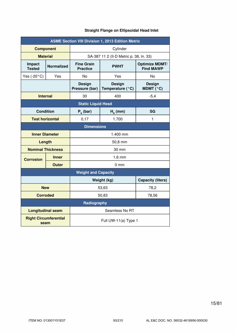
Straight Flange on Ellipsoidal Head Inlet
ASME Section VIII Division 1, 2013 Edition Metric
Component Cylinder
Material SA-387 11 2 (II-D Metric p. 38, ln. 33)
ImpactTested
NormalizedFine GrainPractice
PWHTOptimize MDMT/
Find MAWP
Yes (-20°C) Yes No Yes No
DesignPressure (bar)
DesignTemperature (°C)
DesignMDMT (°C)
Internal 30 400 -5,4
Static Liquid Head
Condition Ps (bar) Hs (mm) SG
Test horizontal 0,17 1.700 1
Dimensions
Inner Diameter 1.400 mm
Length 50,8 mm
Nominal Thickness 30 mm
CorrosionInner 1,6 mm
Outer 0 mm
Weight and Capacity
Weight (kg) Capacity (liters)
New 53,63 78,2
Corroded 50,83 78,56
Radiography
Longitudinal seam Seamless No RT
Right Circumferentialseam
Full UW-11(a) Type 1
15/81
ITEM NO: 013001Y01E07 93/210 AL E&C DOC. NO. 56032-4618956-000030

Results Summary
Governing condition Internal pressure
Minimum thickness per UG-16 1,5 mm + 1,6 mm = 3,1 mm
Design thickness due to internal pressure (t) 16 mm
Maximum allowable working pressure (MAWP) 58,49 bar
Maximum allowable pressure (MAP) 61,84 bar
Rated MDMT -50,9 °C
UCS-66 Material Toughness Requirements
Material impact test temperature per UG-84 = -20°C
tr = 30*701,6 / (1.480*1 - 0.6*30) = 14,4 mm
Stress ratio = tr*E* / (tn - c) = 14,4*1 / (30 - 1,6) = 0,5069
UCS-66(i) reduction in MDMT, TR from Fig UCS-66.1M = 30,9°C
MDMT = max[Timpact - TR, -105] = max[ -20 - 30,9 , -105] = -50,9°C
Design MDMT of -5,4°C is acceptable.
Design thickness, (at 400 °C) UG-27(c)(1)
t = P*R / (S*E - 0,60*P) + Corrosion
= 30*701,6 / (1.480*1,00 - 0,60*30) + 1,6
= 16 mm
Maximum allowable working pressure, (at 400 °C) UG-27(c)(1)
P = S*E*t / (R + 0,60*t) - Ps
= 1.480*1,00*28,4 / (701,6 + 0,60*28,4) - 0
= 58,49 bar
Maximum allowable pressure, (at 20 °C) UG-27(c)(1)
P = S*E*t / (R + 0,60*t)
= 1.480*1,00*30 / (700 + 0,60*30)
= 61,84 bar
% Extreme fiber elongation - UCS-79(d)
EFE = (50*t / Rf)*(1 - Rf / Ro)
= (50*30 / 715)*(1 - 715 / infinity)
= 2,0979%
The extreme fiber elongation does not exceed 5%.
16/81
ITEM NO: 013001Y01E07 94/210 AL E&C DOC. NO. 56032-4618956-000030

Shell- Inlet Chamber
ASME Section VIII Division 1, 2013 Edition Metric
Component Cylinder
Material SA-387 11 2 (II-D Metric p. 38, ln. 33)
ImpactTested
NormalizedFine GrainPractice
PWHTOptimize MDMT/
Find MAWP
Yes (-20°C) Yes No Yes No
DesignPressure (bar)
DesignTemperature (°C)
DesignMDMT (°C)
Internal 30 400 -5,4
Static Liquid Head
Condition Ps (bar) Hs (mm) SG
Test horizontal 0,17 1.700 1
Dimensions
Outer Diameter 1.500 mm
Length 1.400 mm
Nominal Thickness 50 mm
CorrosionInner 1,6 mm
Outer 0 mm
Weight and Capacity
Weight (kg) Capacity (liters)
New 2.192,58 2.155,13
Corroded 2.125,07 2.165
Radiography
Longitudinal seam Full UW-11(a) Type 1
Left Circumferentialseam
Full UW-11(a) Type 1
Right Circumferentialseam
Full UW-11(a) Type 1
17/81
ITEM NO: 013001Y01E07 95/210 AL E&C DOC. NO. 56032-4618956-000030

Results Summary
Governing condition Internal pressure
Minimum thickness per UG-16 1,5 mm + 1,6 mm = 3,1 mm
Design thickness due to internal pressure (t) 16,68 mm
Maximum allowable working pressure (MAWP) 98,04 bar
Maximum allowable pressure (MAP) 101,37 bar
Rated MDMT -105 °C
UCS-66 Material Toughness Requirements
Material impact test temperature per UG-84 = -20°C
tr = 30*750 / (1.480*1 + 0.4*30) = 15,08 mm
Stress ratio = tr*E* / (tn - c) = 15,08*1 / (50 - 1,6) = 0,3116
Stress ratio ≤ 0,35, MDMT per UCS-66(b)(3) = -105°C
MDMT = min[-20 , -105] = -105°C
Design MDMT of -5,4°C is acceptable.
Design thickness, (at 400 °C) Appendix 1-1
t = P*Ro / (S*E + 0,40*P) + Corrosion
= 30*750 / (1.480*1,00 + 0,40*30) + 1,6
= 16,68 mm
Maximum allowable working pressure, (at 400 °C) Appendix 1-1
P = S*E*t / (Ro - 0,40*t) - Ps
= 1.480*1,00*48,4 / (750 - 0,40*48,4) - 0
= 98,04 bar
Maximum allowable pressure, (at 20 °C) Appendix 1-1
P = S*E*t / (Ro - 0,40*t)
= 1.480*1,00*50 / (750 - 0,40*50)
= 101,37 bar
% Extreme fiber elongation - UCS-79(d)
EFE = (50*t / Rf)*(1 - Rf / Ro)
= (50*50 / 725)*(1 - 725 / infinity)
= 3,4483%
The extreme fiber elongation does not exceed 5%.
18/81
ITEM NO: 013001Y01E07 96/210 AL E&C DOC. NO. 56032-4618956-000030

Manhole (A03)
ASME Section VIII Division 1, 2013 Edition Metric
Note: round inside edges per UG-76(c)
Location and Orientation
Located on Ellipsoidal Head Inlet
Orientation 0°
End of nozzle to datum line -700 mm
Calculated as hillside No
Distance to head center, R 0 mm
Passes through a Category A joint No
Nozzle
Access opening No
Material specification SA-182 F11 2 (II-D Metric p. 38, ln. 30) (normalized)
Inside diameter, new 773,13 mm
Nominal wall thickness 54 mm
Corrosion allowance 1,6 mm
Projection available outside vessel, Lpr 46,21 mm
Projection available outside vessel to flange face, Lf 346,21 mm
Local vessel minimum thickness 30 mm
Liquid static head included 0 bar
Longitudinal joint efficiency 1
Welds
Inner fillet, Leg41 9 mm
Nozzle to vessel groove weld 20 mm
19/81
ITEM NO: 013001Y01E07 97/210 AL E&C DOC. NO. 56032-4618956-000030

UCS-66 Material Toughness Requirements Nozzle At Intersection
Material impact test temperature per UG-84 = -20°C
tr = 30*1.403,2*0,996969 / (2*1.480*1 - 0,2*30) = 14,21 mm
Stress ratio = tr*E* / (tn - c) = 14,21*1 / (30 - 1,6) = 0,5003
UCS-66(i) reduction in MDMT, TR from Fig UCS-66.1M = 31,6°C
MDMT = max[Timpact - TR, -105] = max[ -20 - 31,6 , -105] = -51,6°C
Design MDMT of -5,4°C is acceptable.
UCS-66 Material Toughness Requirements Nozzle
Material impact test temperature per UG-84 = -20°C
tr = 30*388,17 / (1.380*1 - 0,6*30) = 8,55 mm
Stress ratio = tr*E* / (tn - c) = 8,55*1 / (54 - 1,6) = 0,1632
Stress ratio ≤ 0,35, MDMT per UCS-66(b)(3) = -105°C
MDMT = min[-20 , -105] = -105°C
Design MDMT of -5,4°C is acceptable.
20/81
ITEM NO: 013001Y01E07 98/210 AL E&C DOC. NO. 56032-4618956-000030
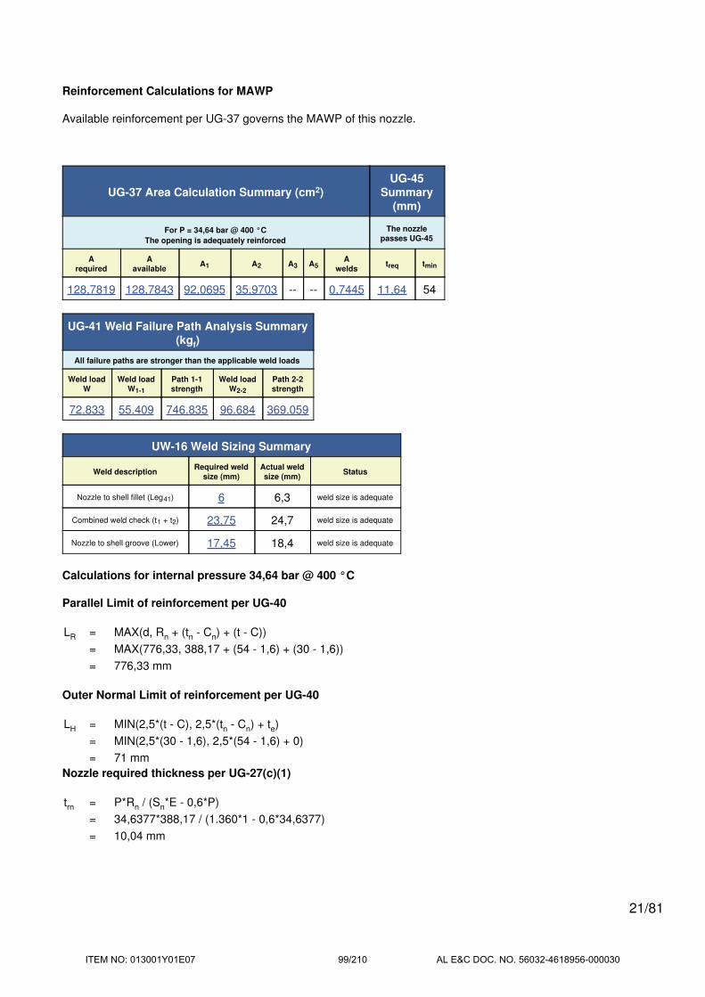
Reinforcement Calculations for MAWP
Available reinforcement per UG-37 governs the MAWP of this nozzle.
UG-37 Area Calculation Summary (cm2)UG-45
Summary(mm)
For P = 34,64 bar @ 400 °C
The opening is adequately reinforced
The nozzle
passes UG-45
A
required
A
availableA1 A2 A3 A5
A
weldstreq tmin
128,7819 128,7843 92,0695 35,9703 -- -- 0,7445 11,64 54
UG-41 Weld Failure Path Analysis Summary(kgf)
All failure paths are stronger than the applicable weld loads
Weld load
W
Weld load
W1-1
Path 1-1
strength
Weld load
W2-2
Path 2-2
strength
72.833 55.409 746.835 96.684 369.059
UW-16 Weld Sizing Summary
Weld descriptionRequired weld
size (mm)
Actual weld
size (mm)Status
Nozzle to shell fillet (Leg41) 6 6,3 weld size is adequate
Combined weld check (t1 + t2) 23,75 24,7 weld size is adequate
Nozzle to shell groove (Lower) 17,45 18,4 weld size is adequate
Calculations for internal pressure 34,64 bar @ 400 °C
Parallel Limit of reinforcement per UG-40
LR = MAX(d, Rn + (tn - Cn) + (t - C))
= MAX(776,33, 388,17 + (54 - 1,6) + (30 - 1,6))
= 776,33 mm
Outer Normal Limit of reinforcement per UG-40
LH = MIN(2,5*(t - C), 2,5*(tn - Cn) + te)
= MIN(2,5*(30 - 1,6), 2,5*(54 - 1,6) + 0)
= 71 mm
Nozzle required thickness per UG-27(c)(1)
trn = P*Rn / (Sn*E - 0,6*P)
= 34,6377*388,17 / (1.360*1 - 0,6*34,6377)
= 10,04 mm
21/81
ITEM NO: 013001Y01E07 99/210 AL E&C DOC. NO. 56032-4618956-000030

Required thickness tr from UG-37(a)
tr = P*D*K / (2*S*E - 0,2*P)
= 34,64*1.403,2*0,996969 / (2*1.480*1 - 0,2*34,64)
= 16,41 mm
Area required per UG-37(c)
Allowable stresses: Sn = 1.386,813, Sv = 1.509,179 kgf/cm2
fr1 = lesser of 1 or Sn / Sv = 0,9189
fr2 = lesser of 1 or Sn / Sv = 0,9189
A = d*tr*F + 2*tn*tr*F*(1 - fr1)
= (776,33*16,41*1 + 2*52,4*16,41*1*(1 - 0,9189)) / 100
= 128,7819 cm2
Area available from FIG. UG-37.1
A1 = larger of the following= 92,0695 cm2
= d*(E1*t - F*tr) - 2*tn*(E1*t - F*tr)*(1 - fr1)
= (776,33*(1*28,4 - 1*16,41) - 2*52,4*(1*28,4 - 1*16,41)*(1 - 0,9189)) / 100
= 92,0695 cm2
= 2*(t + tn)*(E1*t - F*tr) - 2*tn*(E1*t - F*tr)*(1 - fr1)
= (2*(28,4 + 52,4)*(1*28,4 - 1*16,41) - 2*52,4*(1*28,4 - 1*16,41)*(1 - 0,9189)) / 100
= 18,358 cm2
A2 = smaller of the following= 35,9703 cm2
= 2*(tn - trn)*fr2*Lpr
= (2*(52,4 - 10,04)*0,9189*46,21) / 100
= 35,9703 cm2
= 2*(tn - trn)*fr2*Lpr
= (2*(52,4 - 10,04)*0,9189*46,21) / 100
= 35,9703 cm2
A41 = Leg2*fr2= (92*0,9189) / 100
= 0,7445 cm2
Area = A1 + A2 + A41
= 92,0695 + 35,9703 + 0,7445
= 128,7843 cm2
22/81
ITEM NO: 013001Y01E07 100/210 AL E&C DOC. NO. 56032-4618956-000030

As Area >= A the reinforcement is adequate.
UW-16(d) Weld Check
tmin = lesser of 19 mm or tn or t = 19 mm
t1(min) or t2(min) = lesser of 6 mm or 0,7*tmin = 6 mm
t1(actual) = 0,7*Leg = 0.7*9 = 6,3 mm
The weld size t1 is satisfactory.
t2(actual) = 18,4 mm
The weld size t2 is satisfactory.
t1 + t2 = 24,7 >= 1,25*tmin = 23,75
The combined weld sizes for t1 and t2 are satisfactory.
UG-45 Nozzle Neck Thickness Check
Interpretation VIII-1-83-66 has been applied.
ta UG-27 = P*Rn / (Sn*E - 0,6*P) + Corrosion
= 34,6377*388,17 / (1.360*1 - 0,6*34,6377) + 1,6
= 11,64 mm
ta = max[ ta UG-27 , ta UG-22 ]
= max[ 11,64 , 0 ]
= 11,64 mm
tb1 = 18,01 mm
tb1 = max[ tb1 , tb UG16 ]
= max[ 18,01 , 3,1 ]
= 18,01 mm
tb = min[ tb3 , tb1 ]
= min[ 9,93 , 18,01 ]
= 9,93 mm
tUG-45 = max[ ta , tb ]
= max[ 11,64 , 9,93 ]
= 11,64 mm
Available nozzle wall thickness new, tn = 54 mm
The nozzle neck thickness is adequate.
Allowable stresses in joints UG-45 and UW-15(c)
Groove weld in tension: 0,74*1.509,179 = 1.116,792 kgf/cm2
Nozzle wall in shear: 0,7*1.386,813 = 970,769 kgf/cm2
23/81
ITEM NO: 013001Y01E07 101/210 AL E&C DOC. NO. 56032-4618956-000030

Inner fillet weld in shear: 0,49*1.386,813 = 679,538 kgf/cm2
Strength of welded joints:
(1) Inner fillet weld in shear
(π / 2)*Nozzle OD*Leg*Si = (π / 2)*881,13*9*679,538 = 84.648,01 kgf
(3) Nozzle wall in shear
(π / 2)*Mean nozzle dia*tn*Sn = (π / 2)*828,73*52,4*970,769 = 662.186,84 kgf
(4) Groove weld in tension
(π / 2)*Nozzle OD*tw*Sg = (π / 2)*881,13*18,4*1.116,792 = 284.410,6 kgf
Loading on welds per UG-41(b)(1)
W = (A - A1 + 2*tn*fr1*(E1*t - F*tr))*Sv
= (12.878,19 - 9.206,9493 + 2*52,4*0,9189*(1*28,4 - 1*16,41))*1.509,179
= 72.832,64 kgf
W1-1 = (A2 + A5 + A41 + A42)*Sv
= (3.597,0251 + 0 + 74,4515 + 0)*1.509,179
= 55.409,2 kgf
W2-2 = (A2 + A3 + A41 + A43 + 2*tn*t*fr1)*Sv
= (3.597,0251 + 0 + 74,4515 + 0 + 2*52,4*28,4*0,9189)*1.509,179
= 96.684,08 kgf
Load for path 1-1 lesser of W or W1-1 = 55.409,2 kgf
Path 1-1 through (1) & (3) = 84.648,01 + 662.186,84 = 746.834,84 kgf
Path 1-1 is stronger than W1-1 so it is acceptable per UG-41(b)(1).
Load for path 2-2 lesser of W or W2-2 = 72.832,64 kgf
Path 2-2 through (1), (4) = 84.648,01 + 284.410,6 = 369.058,6 kgf
Path 2-2 is stronger than W so it is acceptable per UG-41(b)(2).
24/81
ITEM NO: 013001Y01E07 102/210 AL E&C DOC. NO. 56032-4618956-000030

Reinforcement Calculations for MAP
Available reinforcement per UG-37 governs the MAP of this nozzle.
UG-37 Area Calculation Summary (cm2)UG-45
Summary(mm)
For P = 36,56 bar @ 20 °C
The opening is adequately reinforced
The nozzle
passes UG-45
A
required
A
availableA1 A2 A3 A5
A
weldstreq tmin
135,2975 135,3004 96,9824 37,5625 -- -- 0,7555 10,41 54
UG-41 Weld Failure Path Analysis Summary(kgf)
All failure paths are stronger than the applicable weld loads
Weld load
W
Weld load
W1-1
Path 1-1
strength
Weld load
W2-2
Path 2-2
strength
77.070 57.829 776.998 103.421 395.038
UW-16 Weld Sizing Summary
Weld descriptionRequired weld
size (mm)
Actual weld
size (mm)Status
Nozzle to shell fillet (Leg41) 6 6,3 weld size is adequate
Combined weld check (t1 + t2) 23,75 26,3 weld size is adequate
Nozzle to shell groove (Lower) 17,45 20 weld size is adequate
Calculations for internal pressure 36,56 bar @ 20 °C
Parallel Limit of reinforcement per UG-40
LR = MAX(d, Rn + (tn - Cn) + (t - C))
= MAX(773,13, 386,57 + (54 - 0) + (30 - 0))
= 773,13 mm
Outer Normal Limit of reinforcement per UG-40
LH = MIN(2,5*(t - C), 2,5*(tn - Cn) + te)
= MIN(2,5*(30 - 0), 2,5*(54 - 0) + 0)
= 75 mm
Nozzle required thickness per UG-27(c)(1)
trn = P*Rn / (Sn*E - 0,6*P)
= 36,5635*386,57 / (1.380*1 - 0,6*36,5635)
= 10,41 mm
25/81
ITEM NO: 013001Y01E07 103/210 AL E&C DOC. NO. 56032-4618956-000030

Required thickness tr from UG-37(a)
tr = P*D / (2*S*E - 0,2*P)
= 36,56*1.400 / (2*1.480*1 - 0,2*36,56)
= 17,34 mm
Area required per UG-37(c)
Allowable stresses: Sn = 1.407,207, Sv = 1.509,179 kgf/cm2
fr1 = lesser of 1 or Sn / Sv = 0,9324
fr2 = lesser of 1 or Sn / Sv = 0,9324
A = d*tr*F + 2*tn*tr*F*(1 - fr1)
= (773,13*17,34*1 + 2*54*17,34*1*(1 - 0,9324)) / 100
= 135,2975 cm2
Area available from FIG. UG-37.1
A1 = larger of the following= 96,9824 cm2
= d*(E1*t - F*tr) - 2*tn*(E1*t - F*tr)*(1 - fr1)
= (773,13*(1*30 - 1*17,34) - 2*54*(1*30 - 1*17,34)*(1 - 0,9324)) / 100
= 96,9824 cm2
= 2*(t + tn)*(E1*t - F*tr) - 2*tn*(E1*t - F*tr)*(1 - fr1)
= (2*(30 + 54)*(1*30 - 1*17,34) - 2*54*(1*30 - 1*17,34)*(1 - 0,9324)) / 100
= 20,3503 cm2
A2 = smaller of the following= 37,5625 cm2
= 2*(tn - trn)*fr2*Lpr
= (2*(54 - 10,41)*0,9324*46,21) / 100
= 37,5625 cm2
= 2*(tn - trn)*fr2*Lpr
= (2*(54 - 10,41)*0,9324*46,21) / 100
= 37,5625 cm2
A41 = Leg2*fr2= (92*0,9324) / 100
= 0,7555 cm2
Area = A1 + A2 + A41
= 96,9824 + 37,5625 + 0,7555
= 135,3004 cm2
26/81
ITEM NO: 013001Y01E07 104/210 AL E&C DOC. NO. 56032-4618956-000030

As Area >= A the reinforcement is adequate.
UW-16(d) Weld Check
tmin = lesser of 19 mm or tn or t = 19 mm
t1(min) or t2(min) = lesser of 6 mm or 0,7*tmin = 6 mm
t1(actual) = 0,7*Leg = 0.7*9 = 6,3 mm
The weld size t1 is satisfactory.
t2(actual) = 20 mm
The weld size t2 is satisfactory.
t1 + t2 = 26,3 >= 1,25*tmin = 23,75
The combined weld sizes for t1 and t2 are satisfactory.
UG-45 Nozzle Neck Thickness Check
Interpretation VIII-1-83-66 has been applied.
ta UG-27 = P*Rn / (Sn*E - 0,6*P) + Corrosion
= 36,5635*386,57 / (1.380*1 - 0,6*36,5635) + 0
= 10,41 mm
ta = max[ ta UG-27 , ta UG-22 ]
= max[ 10,41 , 0 ]
= 10,41 mm
tb1 = 17,34 mm
tb1 = max[ tb1 , tb UG16 ]
= max[ 17,34 , 1,5 ]
= 17,34 mm
tb = min[ tb3 , tb1 ]
= min[ 8,33 , 17,34 ]
= 8,33 mm
tUG-45 = max[ ta , tb ]
= max[ 10,41 , 8,33 ]
= 10,41 mm
Available nozzle wall thickness new, tn = 54 mm
The nozzle neck thickness is adequate.
Allowable stresses in joints UG-45 and UW-15(c)
Groove weld in tension: 0,74*1.509,179 = 1.116,792 kgf/cm2
Nozzle wall in shear: 0,7*1.407,207 = 985,045 kgf/cm2
27/81
ITEM NO: 013001Y01E07 105/210 AL E&C DOC. NO. 56032-4618956-000030

Inner fillet weld in shear: 0,49*1.407,207 = 689,532 kgf/cm2
Strength of welded joints:
(1) Inner fillet weld in shear
(π / 2)*Nozzle OD*Leg*Si = (π / 2)*881,13*9*689,532 = 85.892,83 kgf
(3) Nozzle wall in shear
(π / 2)*Mean nozzle dia*tn*Sn = (π / 2)*827,13*54*985,045 = 691.104,79 kgf
(4) Groove weld in tension
(π / 2)*Nozzle OD*tw*Sg = (π / 2)*881,13*20*1.116,792 = 309.145,31 kgf
Loading on welds per UG-41(b)(1)
W = (A - A1 + 2*tn*fr1*(E1*t - F*tr))*Sv
= (13.529,75 - 9.698,2387 + 2*54*0,9324*(1*30 - 1*17,34))*1.509,179
= 77.069,94 kgf
W1-1 = (A2 + A5 + A41 + A42)*Sv
= (3.756,2506 + 0 + 75,5482 + 0)*1.509,179
= 57.828,75 kgf
W2-2 = (A2 + A3 + A41 + A43 + 2*tn*t*fr1)*Sv
= (3.756,2506 + 0 + 75,5482 + 0 + 2*54*30*0,9324)*1.509,179
= 103.420,72 kgf
Load for path 1-1 lesser of W or W1-1 = 57.828,75 kgf
Path 1-1 through (1) & (3) = 85.892,83 + 691.104,79 = 776.997,62 kgf
Path 1-1 is stronger than W1-1 so it is acceptable per UG-41(b)(1).
Load for path 2-2 lesser of W or W2-2 = 77.069,94 kgf
Path 2-2 through (1), (4) = 85.892,83 + 309.145,31 = 395.038,14 kgf
Path 2-2 is stronger than W so it is acceptable per UG-41(b)(2).
28/81
ITEM NO: 013001Y01E07 106/210 AL E&C DOC. NO. 56032-4618956-000030

Inlet (N01)
ASME Section VIII Division 1, 2013 Edition Metric
Note: Per UW-16(b) minimum inside corner radius r1 = min [1 / 4*t , 3 mm] = 3 mm
Location and Orientation
Located on Shell- Inlet Chamber
Orientation 270°
Nozzle center line offset to datum line 700 mm
End of nozzle to shell center 1.000 mm
Passes through a Category A joint No
Nozzle
Access opening No
Material specification SA-387 11 2 (II-D Metric p. 38, ln. 33) (normalized)
Inside diameter, new 896 mm
Wall thickness, tn 50 mm
Minimum wall thickness 25 mm
Corrosion allowance 1,6 mm
Projection available outside vessel, Lpr 250 mm
Heavy barrel length, Lhb 120 mm
Local vessel minimum thickness 50 mm
Liquid static head included 0 bar
Longitudinal joint efficiency 1
Welds
Inner fillet, Leg41 9 mm
Nozzle to vessel groove weld 50 mm
29/81
ITEM NO: 013001Y01E07 107/210 AL E&C DOC. NO. 56032-4618956-000030

UCS-66 Material Toughness Requirements Nozzle At Intersection
Material impact test temperature per UG-84 = -20°C
tr = 30*750 / (1.480*1 + 0,4*30) = 15,08 mm
Stress ratio = tr*E* / (tn - c) = 15,08*1 / (50 - 1,6) = 0,3116
Stress ratio ≤ 0,35, MDMT per UCS-66(b)(3) = -105°C
MDMT = min[-20 , -105] = -105°C
Design MDMT of -5,4°C is acceptable.
UCS-66 Material Toughness Requirements Nozzle
Material impact test temperature per UG-84 = -20°C
External nozzle loadings per UG-22 govern the coincident ratio used.
Stress ratio = tr*E* / (tn - c) = 14,94*1 / (25 - 1,6) = 0,6387
UCS-66(i) reduction in MDMT, TR from Fig UCS-66.1M = 20,2°C
MDMT = max[Timpact - TR, -105] = max[ -20 - 20,2 , -105] = -40,2°C
Design MDMT of -5,4°C is acceptable.
30/81
ITEM NO: 013001Y01E07 108/210 AL E&C DOC. NO. 56032-4618956-000030

Reinforcement Calculations for MAWP
Local stresses at the nozzle OD per WRC 107 govern the MAWP of this nozzle.
UG-37 Area Calculation Summary (cm2)UG-45
Summary(mm)
For P = 34,33 bar @ 400 °C
The opening is adequately reinforced
The nozzle
passes UG-45
A
required
A
availableA1 A2 A3 A5
A
weldstreq tmin
103,3252 217,9318 140,1113 77,0102 -- -- 0,8103 17,26 25
UG-41 Weld Failure Path Analysis Summary
The nozzle is exempt from weld strength calculations per UW-15(b)(1)
UW-16 Weld Sizing Summary
Weld descriptionRequired weld
throat size (mm)
Actual weld
throat size (mm)Status
Nozzle to shell fillet (Leg41) 6 6,3 weld size is adequate
WRC 107
Load CaseP
(bar)
Pr
(kgf)
Mc
(kgf-m)
Vc
(kgf)
ML
(kgf-m)
VL
(kgf)
Mt
(kgf-m)
Max
Comb
Stress
(kgf/cm2)
Allow
Comb
Stress
(kgf/cm2)
Max
Local
Primary
Stress
(kgf/cm2)
Allow
Local
Primary
Stress
(kgf/cm2)
Over
stressed
Load case 1 34,33 13.200,01 94.999,6 0 66.799,7 0 0 4.389,611 4.527,536 2.263,742 2.263,768 No
Load case 1 (Hot Shut
Down)0 13.200,01 94.999,6 0 66.799,7 0 0 -4.320,218 4.527,536 -1.071,829 2.263,768 No
Calculations for internal pressure 34,33 bar @ 400 °C
Parallel Limit of reinforcement per UG-40 and Fig. UG-40 sketch (e-1)
LR = MAX(d, Rn + (tn - Cn) + (t - C))
= MAX(899,2, 449,6 + (25 - 1,6) + (50 - 1,6))
= 899,2 mm
Outer Normal Limit of reinforcement per UG-40 and Fig. UG-40 sketch (e-1)
LH = MIN(2,5*(t - C), 2,5*(tn - Cn) + te)
= MIN(2,5*(50 - 1,6), 2,5*(25 - 1,6) + 43,3)
= 101,8 mm
te = MIN( 120 + 25*tan(30) , 25*tan(60) )
= 43,3 mm
31/81
ITEM NO: 013001Y01E07 109/210 AL E&C DOC. NO. 56032-4618956-000030

Nozzle required thickness per UG-27(c)(1)
trn = P*Rn / (Sn*E - 0,6*P)
= 34,3283*449,6 / (1.480*1 - 0,6*34,3283)
= 10,58 mm
Required thickness tr from UG-37(a)
tr = P*Ro / (S*E + 0,4*P)
= 34,3283*750 / (1.480*1 + 0,4*34,3283)
= 17,24 mm
Area required per UG-37(c)
Allowable stresses: Sn = 1.509,179, Sv = 1.509,179 kgf/cm2
fr1 = lesser of 1 or Sn / Sv = 1
fr2 = lesser of 1 or Sn / Sv = 1
A = d*tr*F + 2*tn*tr*F*(1 - fr1)
= (899,2*17,24*1 + 2*48,4*17,24*1*(1 - 1)) / 100
= 154,9878 cm2
Area available from FIG. UG-37.1
A1 = larger of the following= 280,2233 cm2
= d*(E1*t - F*tr) - 2*tn*(E1*t - F*tr)*(1 - fr1)
= (899,2*(1*48,4 - 1*17,24) - 2*48,4*(1*48,4 - 1*17,24)*(1 - 1)) / 100
= 280,2233 cm2
= 2*(t + tn)*(E1*t - F*tr) - 2*tn*(E1*t - F*tr)*(1 - fr1)
= (2*(48,4 + 48,4)*(1*48,4 - 1*17,24) - 2*48,4*(1*48,4 - 1*17,24)*(1 - 1)) / 100
= 60,3328 cm2
A2 = smaller of the following= 77,0102 cm2
= 5*(tn - trn)*fr2*t - (LIMIT - Lhb)2*fr2 / tan(30)
= (5*(48,4 - 10,58)*1*48,4 - (121 - 120)2*1 / tan(30)) / 100
= 91,5153 cm2
= 2*(tn - trn)*(2,5*tp + te)*fr2= (2*(48,4 - 10,58)*(2,5*23,4 + 43,3)*1) / 100
= 77,0102 cm2
A41 = Leg2*fr2
32/81
ITEM NO: 013001Y01E07 110/210 AL E&C DOC. NO. 56032-4618956-000030

= (92*1) / 100
= 0,8103 cm2
Area = A1 + A2 + A41
= 280,2233 + 77,0102 + 0,8103
= 358,0438 cm2
As Area >= A the reinforcement is adequate.
UW-16(c) Weld Check
Fillet weld: tmin = lesser of 19 mm or tn or t = 19 mm
tc(min) = lesser of 6 mm or 0,7*tmin = 6 mm
tc(actual) = 0,7*Leg = 0.7*9 = 6,3 mm
The fillet weld size is satisfactory.
Weld strength calculations are not required for this detail which conforms to Fig. UW-16.1, sketch (c-e).
UG-45 Nozzle Neck Thickness Check
ta UG-27 = P*Rn / (Sn*E - 0,6*P) + Corrosion
= 34,3283*449,6 / (1.480*1 - 0,6*34,3283) + 1,6
= 12,18 mm
ta UG-22 = 17,26 mm
ta = max[ ta UG-27 , ta UG-22 ]
= max[ 12,18 , 17,26 ]
= 17,26 mm
tb1 = P*Ro / (S*E + 0,4*P) + Corrosion
= 34,3283*750 / (1.480*1 + 0,4*34,3283) + 1,6
= 18,84 mm
tb1 = max[ tb1 , tb UG16 ]
= max[ 18,84 , 3,1 ]
= 18,84 mm
tb = min[ tb3 , tb1 ]
= min[ 9,93 , 18,84 ]
= 9,93 mm
tUG-45 = max[ ta , tb ]
= max[ 17,26 , 9,93 ]
= 17,26 mm
Available nozzle wall thickness new, tn = 25 mm
33/81
ITEM NO: 013001Y01E07 111/210 AL E&C DOC. NO. 56032-4618956-000030

The nozzle neck thickness is adequate.
Check Large Opening per Appendix 1-7(a)
Area required within 75 percent of the limits of reinforcement
= 2 / 3*A = (2 / 3)*154,9878 = 103,3252 cm2
LR = MAX(0,75*d, Rn + (tn - Cn) + (t - C))
= MAX(0,75*899,2, 449,6 + (25 - 1,6) + (50 - 1,6))
= 674,4 mm
A1 = (2*LR - d)*(E1*t - F*tr) - 2*tn*(E1*t - F*tr)*(1 - fr1)
= (2*674,4 - 899,2)*(1*48,4 - 1*17,24) - 2*48,4*(1*48,4 - 1*17,24)*(1 - 1)
= 140,1113 cm2
Area = A1 + A2 + A3 + A41 + A42 + A43 + A5
= 140,1113 + 77,0102 + 0 + 0,8103 + 0 + 0 + 0
= 217,9318 cm2
The area replacement requirements of Appendix 1-7(a) are satisfied.
Check Large Opening per Appendix 1-7(b)
1-7(b)(1)(a) Di = 1.403,2 mm > 1.520 mm False
1-7(b)(1)(b) d = 899,2 mm > 1.020 mm False
1-7(b)(1)(b) d = 899,2 mm > 3,4*(701,6*48,4)0,5 = 626,54 mm True
1-7(b)(1)(c) Rn / R = 449,6 / 701,6 = 0,6408 ≤ 0,7 True
The opening is not within the size range defined by 1-7(b)(1)(a) and (b) so it is exempt from the requirements of
1-7(b)(2),(3) and (4).
Rn / R = 0,6408 does not exceed 0,7 so a U-2(g) analysis is not required per 1-7(b)(1)(c).
34/81
ITEM NO: 013001Y01E07 112/210 AL E&C DOC. NO. 56032-4618956-000030

WRC 107 Load case 1
Applied Loads
Radial load, Pr 13.200,01 kgf
Circumferential moment, Mc 94.999,6 kgf-m
Circumferential shear, Vc 0 kgf
Longitudinal moment, ML 66.799,7 kgf-m
Longitudinal shear, VL 0 kgf
Torsion moment, Mt 0 kgf-m
Internal pressure, P 34,33 bar
Mean shell radius, Rm 725,8 mm
Local shell thickness, T 48,4 mm
Design factor 3
Maximum stresses due to the applied loads at the nozzle OD (includes pressure)
γ = Rm / T = 725,8 / 48,4 = 14,9959
β = 0,875*ro / Rm = 0,875*498 / 725,8 = 0,6004
Pressure stress intensity factor, I = 3,5744 (derived from Division 2 Part 4.5)
Local circumferential pressure stress = I*P*Ri / T =1.813,637 kgf/cm2
Local longitudinal pressure stress = I*P*Ri / (2*T) =906,678 kgf/cm2
Maximum combined stress (PL+P
b+Q) = 4.389,61 kgf/cm2
Allowable combined stress (PL+P
b+Q) = ±3*S = ±4.527,54 kgf/cm2
The maximum combined stress (PL+P
b+Q) is within allowable limits.
Maximum local primary membrane stress (PL) = 2.263,74 kgf/cm2
Allowable local primary membrane stress (PL) = ±1,5*S = ±2.263,77 kgf/cm2
The maximum local primary membrane stress (PL) is within allowable limits.
35/81
ITEM NO: 013001Y01E07 113/210 AL E&C DOC. NO. 56032-4618956-000030

Stresses at the nozzle OD per WRC Bulletin 107
Figure value Au Al Bu Bl Cu Cl Du Dl
3C* Nφ / (P / Rm) 0,8799 0 0 0 0 -33,044 -33,044 -33,044 -33,044
4C* Nφ / (P / Rm) 1,6097 -60,464 -60,464 -60,464 -60,464 0 0 0 0
1C Mφ / P 0,055 0 0 0 0 -185,962 185,962 -185,962 185,962
2C-1 Mφ / P 0,0148 -50,059 50,059 -50,059 50,059 0 0 0 0
3A* Nφ / [Mc / (Rm2*β)] 0,5799 0 0 0 0 -359,901 -359,901 359,901 359,901
1A Mφ / [Mc / (Rm*β)] 0,067 0 0 0 0 -3.741,311 3.741,311 3.741,311 -3.741,311
3B* Nφ / [ML / (Rm2*β)] 1,1699 -510,569 -510,569 510,569 510,569 0 0 0 0
1B-1 Mφ / [ML / (Rm*β)] 0,0135 -530,044 530,044 530,044 -530,044 0 0 0 0
Pressure stress* 1.813,637 1.813,637 1.813,637 1.813,637 507,405 507,405 507,405 507,405
Total circumferential stress 662,502 1.822,706 2.743,727 1.783,756 -3.812,813 4.041,733 4.389,611 -2.721,088
Primary membrane circumferential
stress*1.242,604 1.242,604 2.263,742 2.263,742 114,46 114,46 834,262 834,262
3C* Nx / (P / Rm) 0,8799 -33,044 -33,044 -33,044 -33,044 0 0 0 0
4C* Nx / (P / Rm) 1,6097 0 0 0 0 -60,464 -60,464 -60,464 -60,464
1C-1 Mx / P 0,029 -98,078 98,078 -98,078 98,078 0 0 0 0
2C Mx / P 0,03 0 0 0 0 -101,453 101,453 -101,453 101,453
4A* Nx / [Mc / (Rm2*β)] 1,6296 0 0 0 0 -1.011,365 -1.011,365 1.011,365 1.011,365
2A Mx / [Mc / (Rm*β)] 0,032 0 0 0 0 -1.786,92 1.786,92 1.786,92 -1.786,92
4B* Nx / [ML / (Rm2*β)] 0,5899 -257,394 -257,394 257,394 257,394 0 0 0 0
2B-1 Mx / [ML / (Rm*β)] 0,024 -942,323 942,323 942,323 -942,323 0 0 0 0
Pressure stress* 253,667 253,667 253,667 253,667 906,678 906,678 906,678 906,678
Total longitudinal stress -1.077,172 1.003,631 1.322,262 -366,229 -2.053,524 1.723,222 3.543,046 172,111
Primary membrane longitudinal stress* -36,771 -36,771 478,017 478,017 -165,151 -165,151 1.857,579 1.857,579
Shear from Mt 0 0 0 0 0 0 0 0
Circ shear from Vc 0 0 0 0 0 0 0 0
Long shear from VL 0 0 0 0 0 0 0 0
Total Shear stress 0 0 0 0 0 0 0 0
Combined stress (PL+Pb+Q) -1.739,674 1.822,706 2.743,727 -2.149,985 -3.812,813 4.041,733 4.389,611 2.893,199
* denotes primary stress.
Longitudinal stress in the nozzle wall due to internal pressure + external loads
σn (Pm) = P*Ri / (2*tn) - Pr / (π*(Ro2 - Ri
2)) + M*Ro / I
= 34,33*1,02*449,6 / (2*23,4) - 13.200,01 / (π*(4732 - 449,62))*100 + 1,1613E+08*473 / 7,221E+09*100
= 1.077,55 kgf/cm2
The average primary stress Pm (see Division 2 5.6.a.1) across the nozzle wall due to internal pressure + external
loads is acceptable ( ≤ S = 1.509,179 kgf/cm2)
36/81
ITEM NO: 013001Y01E07 114/210 AL E&C DOC. NO. 56032-4618956-000030

Reinforcement Calculations for MAP
The large opening provisions of Appendix 1-7(a) govern the MAP of this nozzle.
UG-37 Area Calculation Summary (cm2)UG-45
Summary(mm)
For P = 56,29 bar @ 20 °C
The opening is adequately reinforced
The nozzle
passes UG-45
A
required
A
availableA1 A2 A3 A5
A
weldstreq tmin
167,8356 167,8377 98,123 68,9044 -- -- 0,8103 19,29 25
UG-41 Weld Failure Path Analysis Summary
The nozzle is exempt from weld strength calculations per UW-15(b)(1)
UW-16 Weld Sizing Summary
Weld descriptionRequired weld
throat size (mm)
Actual weld
throat size (mm)Status
Nozzle to shell fillet (Leg41) 6 6,3 weld size is adequate
Calculations for internal pressure 56,29 bar @ 20 °C
Parallel Limit of reinforcement per UG-40 and Fig. UG-40 sketch (e-1)
LR = MAX(d, Rn + (tn - Cn) + (t - C))
= MAX(896, 448 + (25 - 0) + (50 - 0))
= 896 mm
Outer Normal Limit of reinforcement per UG-40 and Fig. UG-40 sketch (e-1)
LH = MIN(2,5*(t - C), 2,5*(tn - Cn) + te)
= MIN(2,5*(50 - 0), 2,5*(25 - 0) + 43,3)
= 105,8 mm
te = MIN( 120 + 25*tan(30) , 25*tan(60) )
= 43,3 mm
Nozzle required thickness per UG-27(c)(1)
trn = P*Rn / (Sn*E - 0,6*P)
= 56,2891*448 / (1.480*1 - 0,6*56,2891)
= 17,44 mm
Required thickness tr from UG-37(a)
tr = P*Ro / (S*E + 0,4*P)
= 56,2891*750 / (1.480*1 + 0,4*56,2891)
37/81
ITEM NO: 013001Y01E07 115/210 AL E&C DOC. NO. 56032-4618956-000030

= 28,1 mm
Area required per UG-37(c)
Allowable stresses: Sn = 1.509,179, Sv = 1.509,179 kgf/cm2
fr1 = lesser of 1 or Sn / Sv = 1
fr2 = lesser of 1 or Sn / Sv = 1
A = d*tr*F + 2*tn*tr*F*(1 - fr1)
= (896*28,1*1 + 2*50*28,1*1*(1 - 1)) / 100
= 251,7534 cm2
Area available from FIG. UG-37.1
A1 = larger of the following= 196,2467 cm2
= d*(E1*t - F*tr) - 2*tn*(E1*t - F*tr)*(1 - fr1)
= (896*(1*50 - 1*28,1) - 2*50*(1*50 - 1*28,1)*(1 - 1)) / 100
= 196,2467 cm2
= 2*(t + tn)*(E1*t - F*tr) - 2*tn*(E1*t - F*tr)*(1 - fr1)
= (2*(50 + 50)*(1*50 - 1*28,1) - 2*50*(1*50 - 1*28,1)*(1 - 1)) / 100
= 43,8051 cm2
A2 = smaller of the following= 68,9044 cm2
= 5*(tn - trn)*fr2*t - (LIMIT - Lhb)2*fr2 / tan(30)
= (5*(50 - 17,44)*1*50 - (125 - 120)2*1 / tan(30)) / 100
= 80,974 cm2
= 2*(tn - trn)*(2,5*tp + te)*fr2= (2*(50 - 17,44)*(2,5*25 + 43,3)*1) / 100
= 68,9044 cm2
A41 = Leg2*fr2= (92*1) / 100
= 0,8103 cm2
Area = A1 + A2 + A41
= 196,2467 + 68,9044 + 0,8103
= 265,9614 cm2
As Area >= A the reinforcement is adequate.
38/81
ITEM NO: 013001Y01E07 116/210 AL E&C DOC. NO. 56032-4618956-000030

UW-16(c) Weld Check
Fillet weld: tmin = lesser of 19 mm or tn or t = 19 mm
tc(min) = lesser of 6 mm or 0,7*tmin = 6 mm
tc(actual) = 0,7*Leg = 0.7*9 = 6,3 mm
The fillet weld size is satisfactory.
Weld strength calculations are not required for this detail which conforms to Fig. UW-16.1, sketch (c-e).
UG-45 Nozzle Neck Thickness Check
ta UG-27 = P*Rn / (Sn*E - 0,6*P) + Corrosion
= 56,2891*448 / (1.480*1 - 0,6*56,2891) + 0
= 17,44 mm
ta UG-22 = 19,29 mm
ta = max[ ta UG-27 , ta UG-22 ]
= max[ 17,44 , 19,29 ]
= 19,29 mm
tb1 = P*Ro / (S*E + 0,4*P) + Corrosion
= 56,2891*750 / (1.480*1 + 0,4*56,2891) + 0
= 28,1 mm
tb1 = max[ tb1 , tb UG16 ]
= max[ 28,1 , 1,5 ]
= 28,1 mm
tb = min[ tb3 , tb1 ]
= min[ 8,33 , 28,1 ]
= 8,33 mm
tUG-45 = max[ ta , tb ]
= max[ 19,29 , 8,33 ]
= 19,29 mm
Available nozzle wall thickness new, tn = 25 mm
The nozzle neck thickness is adequate.
Check Large Opening per Appendix 1-7(a)
Area required within 75 percent of the limits of reinforcement
= 2 / 3*A = (2 / 3)*251,7534 = 167,8356 cm2
LR = MAX(0,75*d, Rn + (tn - Cn) + (t - C))
= MAX(0,75*896, 448 + (25 - 0) + (50 - 0))
= 672 mm
39/81
ITEM NO: 013001Y01E07 117/210 AL E&C DOC. NO. 56032-4618956-000030

A1 = (2*LR - d)*(E1*t - F*tr) - 2*tn*(E1*t - F*tr)*(1 - fr1)
= (2*672 - 896)*(1*50 - 1*28,1) - 2*50*(1*50 - 1*28,1)*(1 - 1)
= 98,123 cm2
Area = A1 + A2 + A3 + A41 + A42 + A43 + A5
= 98,123 + 68,9044 + 0 + 0,8103 + 0 + 0 + 0
= 167,8377 cm2
The area replacement requirements of Appendix 1-7(a) are satisfied.
Check Large Opening per Appendix 1-7(b)
1-7(b)(1)(a) Di = 1.400 mm > 1.520 mm False
1-7(b)(1)(b) d = 896 mm > 1.020 mm False
1-7(b)(1)(b) d = 896 mm > 3,4*(700*50)0,5 = 636,08 mm True
1-7(b)(1)(c) Rn / R = 448 / 700 = 0,64 ≤ 0,7 True
The opening is not within the size range defined by 1-7(b)(1)(a) and (b) so it is exempt from the requirements of
1-7(b)(2),(3) and (4).
Rn / R = 0,64 does not exceed 0,7 so a U-2(g) analysis is not required per 1-7(b)(1)(c).
40/81
ITEM NO: 013001Y01E07 118/210 AL E&C DOC. NO. 56032-4618956-000030

Transition #1
ASME Section VIII Division 1, 2013 Edition Metric
Component Cone
Material SA-387 11 2 (II-D Metric p. 38, ln. 33)
ImpactTested
NormalizedFine GrainPractice
PWHTOptimize MDMT/
Find MAWP
Yes (-20°C) Yes No Yes No
DesignPressure (bar)
DesignTemperature (°C)
DesignMDMT (°C)
Internal 30 450 -5,4
Static Liquid Head
Condition Ps (bar) Hs (mm) SG
Test horizontalLarge 0,17 1.700
1
Small 0,16 1.650
Dimensions
Inner DiameterLarge 1.400 mm
Small 1.300 mm
Length 180 mm
Nominal Thickness 25 mm
CorrosionInner 1,6 mm
Outer 0 mm
Weight and Capacity
Weight (kg) Capacity (liters)
New 158,14 257,77
Corroded 148,19 259,04
Radiography
Longitudinal seam Full UW-11(a) Type 1
Left Circumferential seam Full UW-11(a) Type 1
Right Circumferential seam Full UW-11(a) Type 1
41/81
ITEM NO: 013001Y01E07 119/210 AL E&C DOC. NO. 56032-4618956-000030

Results Summary
Governing condition Internal pressure
Minimum thickness per UG-16 1,5 mm + 1,6 mm = 3,1 mm
Design thickness due to internal pressure (t) 17,07 mm
Maximum allowable working pressure (MAWP) 45,08 bar
Maximum allowable pressure (MAP) 49,9 bar
Rated MDMT -40,2 °C
UCS-66 Material Toughness Requirements
Material impact test temperature per UG-84 = -20°C
tr = 30*1.403,32 / (2*0,9635*(1.480*1 - 0.6*30)) = 14,94 mm
Stress ratio = tr*E* / (tn - c) = 14,94*1 / (25 - 1,6) = 0,6386
UCS-66(i) reduction in MDMT, TR from Fig UCS-66.1M = 20,2°C
MDMT = max[Timpact - TR, -105] = max[ -20 - 20,2 , -105] = -40,2°C
Design MDMT of -5,4°C is acceptable.
Design thickness, (at 450 °C) UG-32(g) (Large End)
t = P*D / (2*cos(α)*(S*E - 0,60*P)) + Corrosion
= 30*1.403,32 / (2*cos(15,5241)*(1.430*1,00 - 0,60*30)) + 1,6
= 17,07 mm
Small End design thickness (t = 15,97 mm) does not govern.
Maximum allowable working pressure, (Corroded at 450 °C) UG-32(g) (Large End)
P = 2*S*E*t*cos(α) / (D + 1,20*t*cos(α)) - Ps
=2*1.430*1,00*23,4*cos(15,5241) / (1.403,32 +
1,20*23,4*cos(15,5241)) - 0
= 45,08 bar
Small End MAWP (48,47 bar) does not govern.
Maximum allowable pressure, (New at 20 °C) UG-32(g) (Large End)
P = 2*S*E*t*cos(α) / (D + 1,20*t*cos(α))
=2*1.480*1,00*25*cos(15,5241) / (1.400 +
1,20*25*cos(15,5241))
= 49,9 bar
Small End MAP (53,65 bar) does not govern.
% Extreme fiber elongation - UCS-79(d)
EFE = (50*t / Rf)*(1 - Rf / Ro)
= (50*25,95 / 662,97)*(1 - 662,97 / infinity)
= 1,9568%
The extreme fiber elongation does not exceed 5%.
42/81
ITEM NO: 013001Y01E07 120/210 AL E&C DOC. NO. 56032-4618956-000030

43/81
ITEM NO: 013001Y01E07 121/210 AL E&C DOC. NO. 56032-4618956-000030

Cone juncture large end calculations, P =45,08 barAppendix 1-5(d)
Loading
Area check
required
(∆ < α)
U-2(g)
analysis
required
f1(kgf/cm)
QL(kgf/cm)
ArL(cm2)
AeL(cm2)
Ring
area (cm2)Status
Pressure No No 0 1.612,6 0 49,08 none OK
Cone large end calculations per Appendix 1-5(d)(1), pressure, corroded
Lmin = 2*(RL*ts)0,5
= 2*(701,6*48,4)0,5
= 368,55 mm
The length of the attached cylinder (1.400 mm) ≥ Lmin.
f1 = -Wl / (π*2*Rm) + Ml / (π*R
m
2)
= -10*0 / (π*2*725,8) + 1e4*0 / (π*725,82)
= 0 kgf/cm
P*RL / 2 = 1.612,6 kgf/cm
|f1| <= P*RL / 2 so a U-2(g) analysis is not required.
P / (Ss*E1) = 45,08 / (1.480*1) = 0,03046
From table 1-5.1 ∆ = 30°
As ∆ >= α no additional reinforcement is required.
44/81
ITEM NO: 013001Y01E07 122/210 AL E&C DOC. NO. 56032-4618956-000030

Cone juncture small end calculations, P =45,08 barAppendix 1-5(e)
Loading
Area check
required
(∆ < α)
U-2(g)
analysis
required
f2(kgf/cm)
Qs(kgf/cm)
Ars(cm2)
Aes(cm2)
Ring
area (cm2)Status
Pressure Yes No 0 1.486,18 0,17 10,07 none OK
Cone small end calculations per Appendix 1-5(e)(1), pressure, corroded
Lmin = 1,4*(RS*ts)0,5
= 1,4*(646,6*28,4)0,5
= 189,72 mm
The length of the attached cylinder (1.550 mm) ≥ Lmin.
f2 = -Ws / (π*2*Rm) + Ms / (π*R
m
2)
= -10*0 / (π*2*660,8) + 1e4*0 / (π*660,82)
= 0 kgf/cm
P*Rs / 2 = 1.486,1836 kgf/cm
|f2| <= P*Rs / 2 so a U-2(g) analysis is not required.
P / (Ss*E1) = 45,08 / (1.430*1) = 0,031525
From table 1-5.2 ∆ = 15,38°
As ∆ < α reinforcement is required.
Qs = P*Rs / 2 + f2= 1.486,18 + 0
= 1.486,18 kgf/cm
Ars = (k*Qs*Rs / (Ss*E1))*(1 - ∆ / α)*tan(α)
= (1*1.486,18*646,6 / (10*1.458,193*1))*(1 - 15,38 / 15,5241)*tan(15,5241)
= 0,1699 cm2
Aes = 0,78*(Rs*ts)0,5*[(ts - t) + (tc - tr) / cos(α)]
= 0.01*0,78*(646,6*28,4)0,5*[(28,4 - 20,78) + (23,4 - 21,56) / cos(15,5241)]
= 10,0717 cm2
Aes >= Ars therefore the small end juncture is adequately reinforced.
45/81
ITEM NO: 013001Y01E07 123/210 AL E&C DOC. NO. 56032-4618956-000030

MAP Cone juncture large end calculations, P =49,9 barAppendix 1-5(d)
Loading
Area check
required
(∆ < α)
U-2(g)
analysis
required
f1(kgf/cm)
QL(kgf/cm)
ArL(cm2)
AeL(cm2)
Ring
area (cm2)Status
Pressure No No 0 1.780,88 0 48,48 none OK
Cone large end calculations per Appendix 1-5(d)(1), pressure, new
Lmin = 2*(RL*ts)0,5
= 2*(700*50)0,5
= 374,17 mm
The length of the attached cylinder (1.400 mm) ≥ Lmin.
f1 = -Wl / (π*2*Rm) + Ml / (π*R
m
2)
= -10*0 / (π*2*725) + 1e4*0 / (π*7252)
= 0 kgf/cm
P*RL / 2 = 1.780,88 kgf/cm
|f1| <= P*RL / 2 so a U-2(g) analysis is not required.
P / (Ss*E1) = 49,9 / (1.480*1) = 0,033715
From table 1-5.1 ∆ = 30°
As ∆ >= α no additional reinforcement is required.
46/81
ITEM NO: 013001Y01E07 124/210 AL E&C DOC. NO. 56032-4618956-000030

MAP Cone juncture small end calculations, P =49,9 barAppendix 1-5(e)
Loading
Area check
required
(∆ < α)
U-2(g)
analysis
required
f2(kgf/cm)
Qs(kgf/cm)
Ars(cm2)
Aes(cm2)
Ring
area (cm2)Status
Pressure No No 0 1.640,96 0 10,68 none OK
Cone small end calculations per Appendix 1-5(e)(1), pressure, new
Lmin = 1,4*(RS*ts)0,5
= 1,4*(645*30)0,5
= 194,75 mm
The length of the attached cylinder (1.550 mm) ≥ Lmin.
f2 = -Ws / (π*2*Rm) + Ms / (π*R
m
2)
= -10*0 / (π*2*660) + 1e4*0 / (π*6602)
= 0 kgf/cm
P*Rs / 2 = 1.640,9558 kgf/cm
|f2| <= P*Rs / 2 so a U-2(g) analysis is not required.
P / (Ss*E1) = 49,9 / (1.480*1) = 0,033715
From table 1-5.2 ∆ = 15,93°
As ∆ >= α no additional reinforcement is required.
47/81
ITEM NO: 013001Y01E07 125/210 AL E&C DOC. NO. 56032-4618956-000030
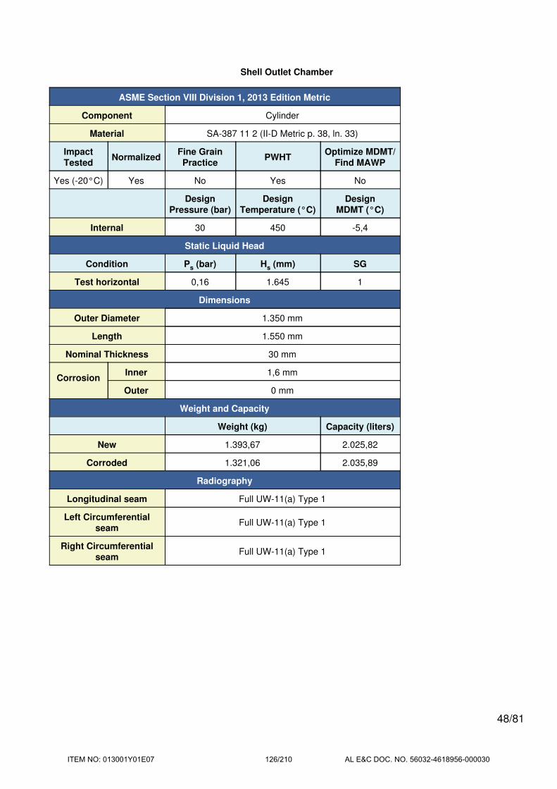
Shell Outlet Chamber
ASME Section VIII Division 1, 2013 Edition Metric
Component Cylinder
Material SA-387 11 2 (II-D Metric p. 38, ln. 33)
ImpactTested
NormalizedFine GrainPractice
PWHTOptimize MDMT/
Find MAWP
Yes (-20°C) Yes No Yes No
DesignPressure (bar)
DesignTemperature (°C)
DesignMDMT (°C)
Internal 30 450 -5,4
Static Liquid Head
Condition Ps (bar) Hs (mm) SG
Test horizontal 0,16 1.645 1
Dimensions
Outer Diameter 1.350 mm
Length 1.550 mm
Nominal Thickness 30 mm
CorrosionInner 1,6 mm
Outer 0 mm
Weight and Capacity
Weight (kg) Capacity (liters)
New 1.393,67 2.025,82
Corroded 1.321,06 2.035,89
Radiography
Longitudinal seam Full UW-11(a) Type 1
Left Circumferentialseam
Full UW-11(a) Type 1
Right Circumferentialseam
Full UW-11(a) Type 1
48/81
ITEM NO: 013001Y01E07 126/210 AL E&C DOC. NO. 56032-4618956-000030

Results Summary
Governing condition Internal pressure
Minimum thickness per UG-16 1,5 mm + 1,6 mm = 3,1 mm
Design thickness due to internal pressure (t) 15,64 mm
Maximum allowable working pressure (MAWP) 61,2 bar
Maximum allowable pressure (MAP) 66,97 bar
Rated MDMT -54,3 °C
UCS-66 Material Toughness Requirements
Material impact test temperature per UG-84 = -20°C
tr = 30*675 / (1.480*1 + 0.4*30) = 13,57 mm
Stress ratio = tr*E* / (tn - c) = 13,57*1 / (30 - 1,6) = 0,4779
UCS-66(i) reduction in MDMT, TR from Fig UCS-66.1M = 34,3°C
MDMT = max[Timpact - TR, -105] = max[ -20 - 34,3 , -105] = -54,3°C
Design MDMT of -5,4°C is acceptable.
Design thickness, (at 450 °C) Appendix 1-1
t = P*Ro / (S*E + 0,40*P) + Corrosion
= 30*675 / (1.430*1,00 + 0,40*30) + 1,6
= 15,64 mm
Maximum allowable working pressure, (at 450 °C) Appendix 1-1
P = S*E*t / (Ro - 0,40*t) - Ps
= 1.430*1,00*28,4 / (675 - 0,40*28,4) - 0
= 61,2 bar
Maximum allowable pressure, (at 20 °C) Appendix 1-1
P = S*E*t / (Ro - 0,40*t)
= 1.480*1,00*30 / (675 - 0,40*30)
= 66,97 bar
% Extreme fiber elongation - UCS-79(d)
EFE = (50*t / Rf)*(1 - Rf / Ro)
= (50*30 / 660)*(1 - 660 / infinity)
= 2,2727%
The extreme fiber elongation does not exceed 5%.
49/81
ITEM NO: 013001Y01E07 127/210 AL E&C DOC. NO. 56032-4618956-000030

Manhole (A04)
ASME Section VIII Division 1, 2013 Edition Metric
Note: round inside edges per UG-76(c)
Location and Orientation
Located on Shell Outlet Chamber
Orientation 270°
Nozzle center line offset to datum line 2.430 mm
End of nozzle to shell center 1.045 mm
Passes through a Category A joint No
Nozzle
Access opening No
Material specification SA-182 F11 2 (II-D Metric p. 38, ln. 30) (normalized)
Inside diameter, new 601,7 mm
Nominal wall thickness 50 mm
Corrosion allowance 1,6 mm
Projection available outside vessel, Lpr 40 mm
Projection available outside vessel to flange face, Lf 370 mm
Local vessel minimum thickness 30 mm
Liquid static head included 0 bar
Longitudinal joint efficiency 1
Welds
Inner fillet, Leg41 9 mm
Nozzle to vessel groove weld 30 mm
50/81
ITEM NO: 013001Y01E07 128/210 AL E&C DOC. NO. 56032-4618956-000030
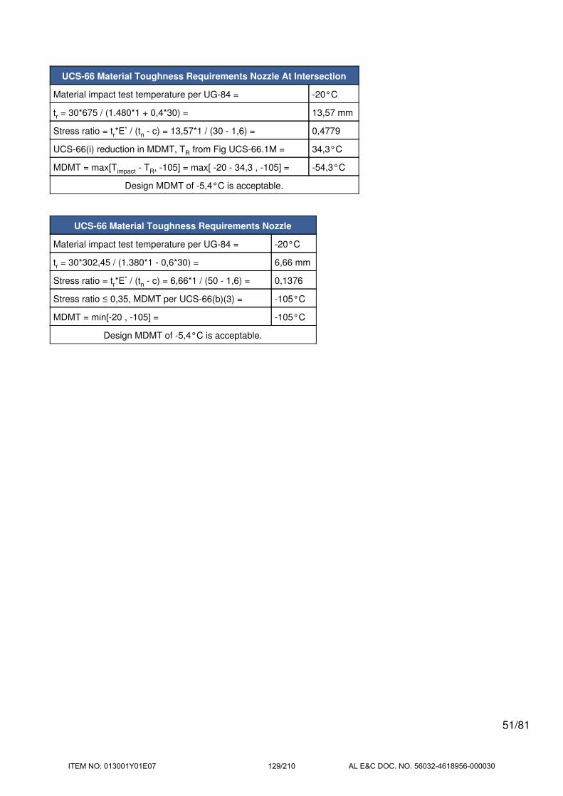
UCS-66 Material Toughness Requirements Nozzle At Intersection
Material impact test temperature per UG-84 = -20°C
tr = 30*675 / (1.480*1 + 0,4*30) = 13,57 mm
Stress ratio = tr*E* / (tn - c) = 13,57*1 / (30 - 1,6) = 0,4779
UCS-66(i) reduction in MDMT, TR from Fig UCS-66.1M = 34,3°C
MDMT = max[Timpact - TR, -105] = max[ -20 - 34,3 , -105] = -54,3°C
Design MDMT of -5,4°C is acceptable.
UCS-66 Material Toughness Requirements Nozzle
Material impact test temperature per UG-84 = -20°C
tr = 30*302,45 / (1.380*1 - 0,6*30) = 6,66 mm
Stress ratio = tr*E* / (tn - c) = 6,66*1 / (50 - 1,6) = 0,1376
Stress ratio ≤ 0,35, MDMT per UCS-66(b)(3) = -105°C
MDMT = min[-20 , -105] = -105°C
Design MDMT of -5,4°C is acceptable.
51/81
ITEM NO: 013001Y01E07 129/210 AL E&C DOC. NO. 56032-4618956-000030

Reinforcement Calculations for MAWP
The large opening provisions of Appendix 1-7(a) govern the MAWP of this nozzle.
UG-37 Area Calculation Summary (cm2)UG-45
Summary(mm)
For P = 34,51 bar @ 450 °C
The opening is adequately reinforced
The nozzle
passes UG-45
A
required
A
availableA1 A2 A3 A5
A
weldstreq tmin
66,015 66,0179 36,0148 29,267 -- -- 0,7361 9,93 50
UG-41 Weld Failure Path Analysis Summary
The nozzle is exempt from weld strength calculations per UW-15(b)(1)
UW-16 Weld Sizing Summary
Weld descriptionRequired weld
throat size (mm)
Actual weld
throat size (mm)Status
Nozzle to shell fillet (Leg41) 6 6,3 weld size is adequate
Calculations for internal pressure 34,51 bar @ 450 °C
Parallel Limit of reinforcement per UG-40
LR = MAX(d, Rn + (tn - Cn) + (t - C))
= MAX(604,9, 302,45 + (50 - 1,6) + (30 - 1,6))
= 604,9 mm
Outer Normal Limit of reinforcement per UG-40
LH = MIN(2,5*(t - C), 2,5*(tn - Cn) + te)
= MIN(2,5*(30 - 1,6), 2,5*(50 - 1,6) + 0)
= 71 mm
Nozzle required thickness per UG-27(c)(1)
trn = P*Rn / (Sn*E - 0,6*P)
= 34,5132*302,45 / (1.300*1 - 0,6*34,5132)
= 8,16 mm
Required thickness tr from UG-37(a)
tr = P*Ro / (S*E + 0,4*P)
= 34,5132*675 / (1.430*1 + 0,4*34,5132)
= 16,14 mm
52/81
ITEM NO: 013001Y01E07 130/210 AL E&C DOC. NO. 56032-4618956-000030

Area required per UG-37(c)
Allowable stresses: Sn = 1.325,63, Sv = 1.458,193 kgf/cm2
fr1 = lesser of 1 or Sn / Sv = 0,9091
fr2 = lesser of 1 or Sn / Sv = 0,9091
A = d*tr*F + 2*tn*tr*F*(1 - fr1)
= (604,9*16,14*1 + 2*48,4*16,14*1*(1 - 0,9091)) / 100
= 99,0225 cm2
Area available from FIG. UG-37.1
A1 = larger of the following= 73,1082 cm2
= d*(E1*t - F*tr) - 2*tn*(E1*t - F*tr)*(1 - fr1)
= (604,9*(1*28,4 - 1*16,14) - 2*48,4*(1*28,4 - 1*16,14)*(1 - 0,9091)) / 100
= 73,1082 cm2
= 2*(t + tn)*(E1*t - F*tr) - 2*tn*(E1*t - F*tr)*(1 - fr1)
= (2*(28,4 + 48,4)*(1*28,4 - 1*16,14) - 2*48,4*(1*28,4 - 1*16,14)*(1 - 0,9091)) / 100
= 17,7587 cm2
A2 = smaller of the following= 29,267 cm2
= 2*(tn - trn)*fr2*Lpr
= (2*(48,4 - 8,16)*0,9091*40) / 100
= 29,267 cm2
= 2*(tn - trn)*fr2*Lpr
= (2*(48,4 - 8,16)*0,9091*40) / 100
= 29,267 cm2
A41 = Leg2*fr2= (92*0,9091) / 100
= 0,7361 cm2
Area = A1 + A2 + A41
= 73,1082 + 29,267 + 0,7361
= 103,1114 cm2
As Area >= A the reinforcement is adequate.
53/81
ITEM NO: 013001Y01E07 131/210 AL E&C DOC. NO. 56032-4618956-000030

UW-16(c) Weld Check
Fillet weld: tmin = lesser of 19 mm or tn or t = 19 mm
tc(min) = lesser of 6 mm or 0,7*tmin = 6 mm
tc(actual) = 0,7*Leg = 0.7*9 = 6,3 mm
The fillet weld size is satisfactory.
Weld strength calculations are not required for this detail which conforms to Fig. UW-16.1, sketch (c-e).
UG-45 Nozzle Neck Thickness Check
ta UG-27 = P*Rn / (Sn*E - 0,6*P) + Corrosion
= 34,5132*302,45 / (1.300*1 - 0,6*34,5132) + 1,6
= 9,76 mm
ta = max[ ta UG-27 , ta UG-22 ]
= max[ 9,76 , 0 ]
= 9,76 mm
tb1 = P*Ro / (S*E + 0,4*P) + Corrosion
= 34,5132*675 / (1.430*1 + 0,4*34,5132) + 1,6
= 17,74 mm
tb1 = max[ tb1 , tb UG16 ]
= max[ 17,74 , 3,1 ]
= 17,74 mm
tb = min[ tb3 , tb1 ]
= min[ 9,93 , 17,74 ]
= 9,93 mm
tUG-45 = max[ ta , tb ]
= max[ 9,76 , 9,93 ]
= 9,93 mm
Available nozzle wall thickness new, tn = 50 mm
The nozzle neck thickness is adequate.
Check Large Opening per Appendix 1-7(a)
Area required within 75 percent of the limits of reinforcement
= 2 / 3*A = (2 / 3)*99,0225 = 66,015 cm2
LR = MAX(0,75*d, Rn + (tn - Cn) + (t - C))
= MAX(0,75*604,9, 302,45 + (50 - 1,6) + (30 - 1,6))
= 453,68 mm
A1 = (2*LR - d)*(E1*t - F*tr) - 2*tn*(E1*t - F*tr)*(1 - fr1)
54/81
ITEM NO: 013001Y01E07 132/210 AL E&C DOC. NO. 56032-4618956-000030

= (2*453,68 - 604,9)*(1*28,4 - 1*16,14) - 2*48,4*(1*28,4 - 1*16,14)*(1 - 0,9091)
= 36,0148 cm2
Area = A1 + A2 + A3 + A41 + A42 + A43 + A5
= 36,0148 + 29,267 + 0 + 0,7361 + 0 + 0 + 0
= 66,0179 cm2
The area replacement requirements of Appendix 1-7(a) are satisfied.
Check Large Opening per Appendix 1-7(b)
1-7(b)(1)(a) Di = 1.293,2 mm > 1.520 mm False
1-7(b)(1)(b) d = 604,9 mm > 1.020 mm False
1-7(b)(1)(b) d = 604,9 mm > 3,4*(646,6*28,4)0,5 = 460,74 mm True
1-7(b)(1)(c) Rn / R = 302,45 / 646,6 = 0,4678 ≤ 0,7 True
The opening is not within the size range defined by 1-7(b)(1)(a) and (b) so it is exempt from the requirements of
1-7(b)(2),(3) and (4).
Rn / R = 0,4678 does not exceed 0,7 so a U-2(g) analysis is not required per 1-7(b)(1)(c).
55/81
ITEM NO: 013001Y01E07 133/210 AL E&C DOC. NO. 56032-4618956-000030

Reinforcement Calculations for MAP
The large opening provisions of Appendix 1-7(a) govern the MAP of this nozzle.
UG-37 Area Calculation Summary (cm2)UG-45
Summary(mm)
For P = 37,99 bar @ 20 °C
The opening is adequately reinforced
The nozzle
passes UG-45
A
required
A
availableA1 A2 A3 A5
A
weldstreq tmin
69,5635 69,5644 37,7935 31,0154 -- -- 0,7555 8,42 50
UG-41 Weld Failure Path Analysis Summary
The nozzle is exempt from weld strength calculations per UW-15(b)(1)
UW-16 Weld Sizing Summary
Weld descriptionRequired weld
throat size (mm)
Actual weld
throat size (mm)Status
Nozzle to shell fillet (Leg41) 6 6,3 weld size is adequate
Calculations for internal pressure 37,99 bar @ 20 °C
Parallel Limit of reinforcement per UG-40
LR = MAX(d, Rn + (tn - Cn) + (t - C))
= MAX(601,7, 300,85 + (50 - 0) + (30 - 0))
= 601,7 mm
Outer Normal Limit of reinforcement per UG-40
LH = MIN(2,5*(t - C), 2,5*(tn - Cn) + te)
= MIN(2,5*(30 - 0), 2,5*(50 - 0) + 0)
= 75 mm
Nozzle required thickness per UG-27(c)(1)
trn = P*Rn / (Sn*E - 0,6*P)
= 37,9868*300,85 / (1.380*1 - 0,6*37,9868)
= 8,42 mm
Required thickness tr from UG-37(a)
tr = P*Ro / (S*E + 0,4*P)
= 37,9868*675 / (1.480*1 + 0,4*37,9868)
= 17,15 mm
56/81
ITEM NO: 013001Y01E07 134/210 AL E&C DOC. NO. 56032-4618956-000030

Area required per UG-37(c)
Allowable stresses: Sn = 1.407,207, Sv = 1.509,179 kgf/cm2
fr1 = lesser of 1 or Sn / Sv = 0,9324
fr2 = lesser of 1 or Sn / Sv = 0,9324
A = d*tr*F + 2*tn*tr*F*(1 - fr1)
= (601,7*17,15*1 + 2*50*17,15*1*(1 - 0,9324)) / 100
= 104,3452 cm2
Area available from FIG. UG-37.1
A1 = larger of the following= 76,4553 cm2
= d*(E1*t - F*tr) - 2*tn*(E1*t - F*tr)*(1 - fr1)
= (601,7*(1*30 - 1*17,15) - 2*50*(1*30 - 1*17,15)*(1 - 0,9324)) / 100
= 76,4553 cm2
= 2*(t + tn)*(E1*t - F*tr) - 2*tn*(E1*t - F*tr)*(1 - fr1)
= (2*(30 + 50)*(1*30 - 1*17,15) - 2*50*(1*30 - 1*17,15)*(1 - 0,9324)) / 100
= 19,6929 cm2
A2 = smaller of the following= 31,0154 cm2
= 2*(tn - trn)*fr2*Lpr
= (2*(50 - 8,42)*0,9324*40) / 100
= 31,0154 cm2
= 2*(tn - trn)*fr2*Lpr
= (2*(50 - 8,42)*0,9324*40) / 100
= 31,0154 cm2
A41 = Leg2*fr2= (92*0,9324) / 100
= 0,7555 cm2
Area = A1 + A2 + A41
= 76,4553 + 31,0154 + 0,7555
= 108,2262 cm2
As Area >= A the reinforcement is adequate.
57/81
ITEM NO: 013001Y01E07 135/210 AL E&C DOC. NO. 56032-4618956-000030

UW-16(c) Weld Check
Fillet weld: tmin = lesser of 19 mm or tn or t = 19 mm
tc(min) = lesser of 6 mm or 0,7*tmin = 6 mm
tc(actual) = 0,7*Leg = 0.7*9 = 6,3 mm
The fillet weld size is satisfactory.
Weld strength calculations are not required for this detail which conforms to Fig. UW-16.1, sketch (c-e).
UG-45 Nozzle Neck Thickness Check
ta UG-27 = P*Rn / (Sn*E - 0,6*P) + Corrosion
= 37,9868*300,85 / (1.380*1 - 0,6*37,9868) + 0
= 8,42 mm
ta = max[ ta UG-27 , ta UG-22 ]
= max[ 8,42 , 0 ]
= 8,42 mm
tb1 = P*Ro / (S*E + 0,4*P) + Corrosion
= 37,9868*675 / (1.480*1 + 0,4*37,9868) + 0
= 17,15 mm
tb1 = max[ tb1 , tb UG16 ]
= max[ 17,15 , 1,5 ]
= 17,15 mm
tb = min[ tb3 , tb1 ]
= min[ 8,33 , 17,15 ]
= 8,33 mm
tUG-45 = max[ ta , tb ]
= max[ 8,42 , 8,33 ]
= 8,42 mm
Available nozzle wall thickness new, tn = 50 mm
The nozzle neck thickness is adequate.
Check Large Opening per Appendix 1-7(a)
Area required within 75 percent of the limits of reinforcement
= 2 / 3*A = (2 / 3)*104,3452 = 69,5635 cm2
LR = MAX(0,75*d, Rn + (tn - Cn) + (t - C))
= MAX(0,75*601,7, 300,85 + (50 - 0) + (30 - 0))
= 451,28 mm
A1 = (2*LR - d)*(E1*t - F*tr) - 2*tn*(E1*t - F*tr)*(1 - fr1)
58/81
ITEM NO: 013001Y01E07 136/210 AL E&C DOC. NO. 56032-4618956-000030

= (2*451,28 - 601,7)*(1*30 - 1*17,15) - 2*50*(1*30 - 1*17,15)*(1 - 0,9324)
= 37,7935 cm2
Area = A1 + A2 + A3 + A41 + A42 + A43 + A5
= 37,7935 + 31,0154 + 0 + 0,7555 + 0 + 0 + 0
= 69,5644 cm2
The area replacement requirements of Appendix 1-7(a) are satisfied.
Check Large Opening per Appendix 1-7(b)
1-7(b)(1)(a) Di = 1.290 mm > 1.520 mm False
1-7(b)(1)(b) d = 601,7 mm > 1.020 mm False
1-7(b)(1)(b) d = 601,7 mm > 3,4*(645*30)0,5 = 472,95 mm True
1-7(b)(1)(c) Rn / R = 300,85 / 645 = 0,4664 ≤ 0,7 True
The opening is not within the size range defined by 1-7(b)(1)(a) and (b) so it is exempt from the requirements of
1-7(b)(2),(3) and (4).
Rn / R = 0,4664 does not exceed 0,7 so a U-2(g) analysis is not required per 1-7(b)(1)(c).
59/81
ITEM NO: 013001Y01E07 137/210 AL E&C DOC. NO. 56032-4618956-000030
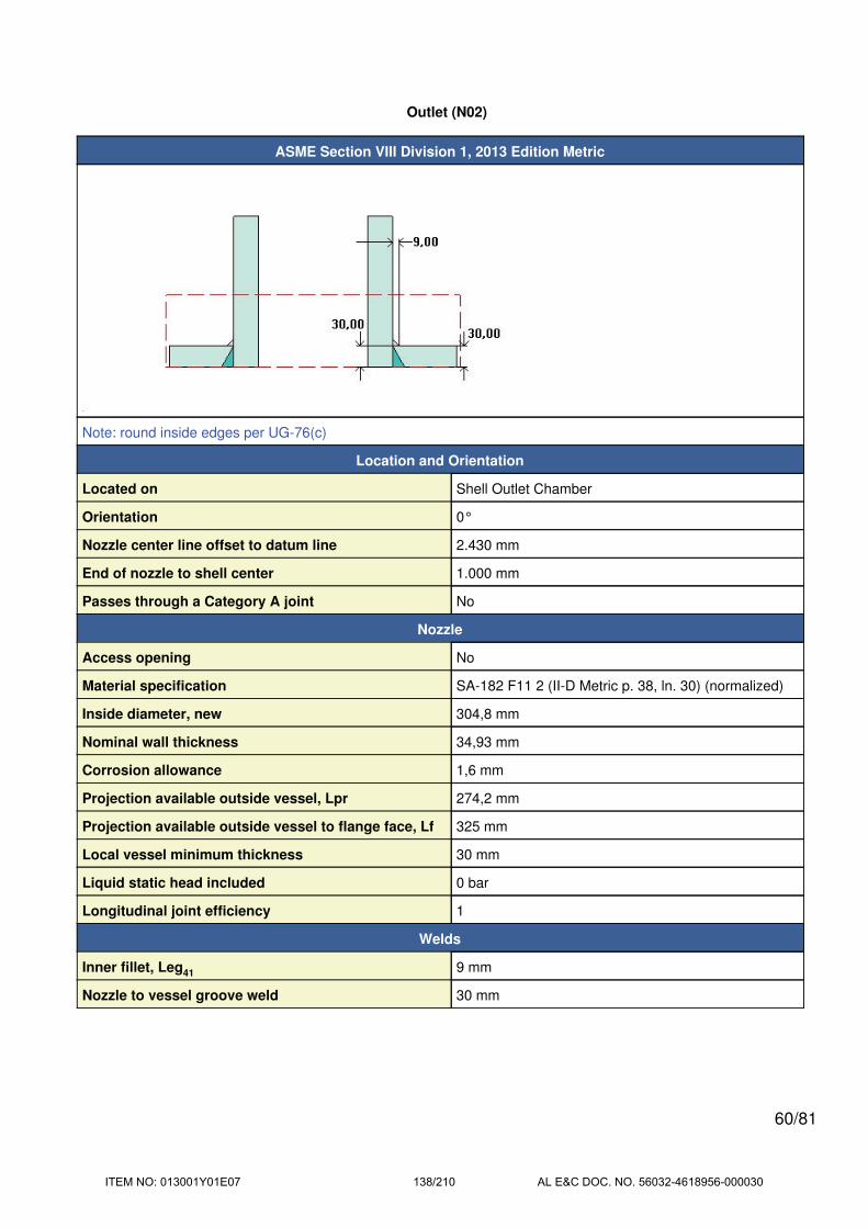
Outlet (N02)
ASME Section VIII Division 1, 2013 Edition Metric
Note: round inside edges per UG-76(c)
Location and Orientation
Located on Shell Outlet Chamber
Orientation 0°
Nozzle center line offset to datum line 2.430 mm
End of nozzle to shell center 1.000 mm
Passes through a Category A joint No
Nozzle
Access opening No
Material specification SA-182 F11 2 (II-D Metric p. 38, ln. 30) (normalized)
Inside diameter, new 304,8 mm
Nominal wall thickness 34,93 mm
Corrosion allowance 1,6 mm
Projection available outside vessel, Lpr 274,2 mm
Projection available outside vessel to flange face, Lf 325 mm
Local vessel minimum thickness 30 mm
Liquid static head included 0 bar
Longitudinal joint efficiency 1
Welds
Inner fillet, Leg41 9 mm
Nozzle to vessel groove weld 30 mm
60/81
ITEM NO: 013001Y01E07 138/210 AL E&C DOC. NO. 56032-4618956-000030

ASME B16.5-2009 Flange
Description NPS 12 Class 300 LWN A182 F11 Cl.2 N
Bolt Material SA-193 B7 Bolt <= 64 (II-D Metric p. 352, ln. 31)
Blind included No
Rated MDMT -44,6°C
Liquid static head 0 bar
Consider External Loads on Flange MAWP Rating No
MAWP rating 33,7 bar @ 450°C
MAP rating 51,7 bar @ 20°C
Hydrotest rating 78 bar @ 20°C
PWHT performed Yes
Impact Tested Yes (-20°C)
Gasket
Description Flexitallic Spiral Wound CGI 316 S.S.
Notes
Flange is impact tested per UG-84 to -20°C.
UCS-66(i) reduction of 24,6°C applied (ratio = 0,5803).
Bolts rated MDMT per Fig UCS-66 note (c) = -48°C
ASME B16.5: Use normalized and tempered flange material only.
UCS-66 Material Toughness Requirements
LWN rated MDMT per UCS-66(c)(4) = -44,6°C
Design MDMT of -5,4°C is acceptable.
61/81
ITEM NO: 013001Y01E07 139/210 AL E&C DOC. NO. 56032-4618956-000030
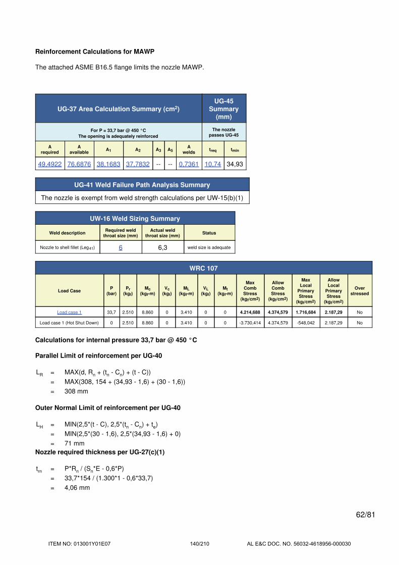
Reinforcement Calculations for MAWP
The attached ASME B16.5 flange limits the nozzle MAWP.
UG-37 Area Calculation Summary (cm2)UG-45
Summary(mm)
For P = 33,7 bar @ 450 °C
The opening is adequately reinforced
The nozzle
passes UG-45
A
required
A
availableA1 A2 A3 A5
A
weldstreq tmin
49,4922 76,6876 38,1683 37,7832 -- -- 0,7361 10,74 34,93
UG-41 Weld Failure Path Analysis Summary
The nozzle is exempt from weld strength calculations per UW-15(b)(1)
UW-16 Weld Sizing Summary
Weld descriptionRequired weld
throat size (mm)
Actual weld
throat size (mm)Status
Nozzle to shell fillet (Leg41) 6 6,3 weld size is adequate
WRC 107
Load CaseP
(bar)
Pr
(kgf)
Mc
(kgf-m)
Vc
(kgf)
ML
(kgf-m)
VL
(kgf)
Mt
(kgf-m)
Max
Comb
Stress
(kgf/cm2)
Allow
Comb
Stress
(kgf/cm2)
Max
Local
Primary
Stress
(kgf/cm2)
Allow
Local
Primary
Stress
(kgf/cm2)
Over
stressed
Load case 1 33,7 2.510 8.860 0 3.410 0 0 4.214,688 4.374,579 1.716,684 2.187,29 No
Load case 1 (Hot Shut Down) 0 2.510 8.860 0 3.410 0 0 -3.730,414 4.374,579 -548,042 2.187,29 No
Calculations for internal pressure 33,7 bar @ 450 °C
Parallel Limit of reinforcement per UG-40
LR = MAX(d, Rn + (tn - Cn) + (t - C))
= MAX(308, 154 + (34,93 - 1,6) + (30 - 1,6))
= 308 mm
Outer Normal Limit of reinforcement per UG-40
LH = MIN(2,5*(t - C), 2,5*(tn - Cn) + te)
= MIN(2,5*(30 - 1,6), 2,5*(34,93 - 1,6) + 0)
= 71 mm
Nozzle required thickness per UG-27(c)(1)
trn = P*Rn / (Sn*E - 0,6*P)
= 33,7*154 / (1.300*1 - 0,6*33,7)
= 4,06 mm
62/81
ITEM NO: 013001Y01E07 140/210 AL E&C DOC. NO. 56032-4618956-000030

Required thickness tr from UG-37(a)
tr = P*Ro / (S*E + 0,4*P)
= 33,7*675 / (1.430*1 + 0,4*33,7)
= 15,76 mm
Area required per UG-37(c)
Allowable stresses: Sn = 1.325,63, Sv = 1.458,193 kgf/cm2
fr1 = lesser of 1 or Sn / Sv = 0,9091
fr2 = lesser of 1 or Sn / Sv = 0,9091
A = d*tr*F + 2*tn*tr*F*(1 - fr1)
= (308*15,76*1 + 2*33,33*15,76*1*(1 - 0,9091)) / 100
= 49,4922 cm2
Area available from FIG. UG-37.1
A1 = larger of the following= 38,1683 cm2
= d*(E1*t - F*tr) - 2*tn*(E1*t - F*tr)*(1 - fr1)
= (308*(1*28,4 - 1*15,76) - 2*33,33*(1*28,4 - 1*15,76)*(1 - 0,9091)) / 100
= 38,1683 cm2
= 2*(t + tn)*(E1*t - F*tr) - 2*tn*(E1*t - F*tr)*(1 - fr1)
= (2*(28,4 + 33,33)*(1*28,4 - 1*15,76) - 2*33,33*(1*28,4 - 1*15,76)*(1 - 0,9091)) / 100
= 14,8393 cm2
A2 = smaller of the following= 37,7832 cm2
= 5*(tn - trn)*fr2*t
= (5*(33,33 - 4,06)*0,9091*28,4) / 100
= 37,7832 cm2
= 5*(tn - trn)*fr2*tn= (5*(33,33 - 4,06)*0,9091*33,33) / 100
= 44,336 cm2
A41 = Leg2*fr2= (92*0,9091) / 100
= 0,7361 cm2
Area = A1 + A2 + A41
= 38,1683 + 37,7832 + 0,7361
63/81
ITEM NO: 013001Y01E07 141/210 AL E&C DOC. NO. 56032-4618956-000030

= 76,6876 cm2
As Area >= A the reinforcement is adequate.
UW-16(c) Weld Check
Fillet weld: tmin = lesser of 19 mm or tn or t = 19 mm
tc(min) = lesser of 6 mm or 0,7*tmin = 6 mm
tc(actual) = 0,7*Leg = 0.7*9 = 6,3 mm
The fillet weld size is satisfactory.
Weld strength calculations are not required for this detail which conforms to Fig. UW-16.1, sketch (c-e).
UG-45 Nozzle Neck Thickness Check
ta UG-27 = P*Rn / (Sn*E - 0,6*P) + Corrosion
= 33,7*154 / (1.300*1 - 0,6*33,7) + 1,6
= 5,66 mm
ta UG-22 = 10,74 mm
ta = max[ ta UG-27 , ta UG-22 ]
= max[ 5,66 , 10,74 ]
= 10,74 mm
tb1 = P*Ro / (S*E + 0,4*P) + Corrosion
= 33,7*675 / (1.430*1 + 0,4*33,7) + 1,6
= 17,36 mm
tb1 = max[ tb1 , tb UG16 ]
= max[ 17,36 , 3,1 ]
= 17,36 mm
tb = min[ tb3 , tb1 ]
= min[ 9,93 , 17,36 ]
= 9,93 mm
tUG-45 = max[ ta , tb ]
= max[ 10,74 , 9,93 ]
= 10,74 mm
Available nozzle wall thickness new, tn = 34,93 mm
The nozzle neck thickness is adequate.
64/81
ITEM NO: 013001Y01E07 142/210 AL E&C DOC. NO. 56032-4618956-000030

WRC 107 Load case 1
Applied Loads
Radial load, Pr 2.510 kgf
Circumferential moment, Mc 8.860 kgf-m
Circumferential shear, Vc 0 kgf
Longitudinal moment, ML 3.410 kgf-m
Longitudinal shear, VL 0 kgf
Torsion moment, Mt 0 kgf-m
Internal pressure, P 33,7 bar
Mean shell radius, Rm 660,8 mm
Local shell thickness, T 28,4 mm
Design factor 3
Maximum stresses due to the applied loads at the nozzle OD (includes pressure)
γ = Rm / T = 660,8 / 28,4 = 23,2678
β = 0,875*ro / Rm = 0,875*187,33 / 660,8 = 0,248
Pressure stress intensity factor, I = 1,902 (derived from Division 2 Part 4.5)
Local circumferential pressure stress = I*P*Ri / T =1.488,046 kgf/cm2
Local longitudinal pressure stress = I*P*Ri / (2*T) =744,058 kgf/cm2
Maximum combined stress (PL+P
b+Q) = 4.214,69 kgf/cm2
Allowable combined stress (PL+P
b+Q) = ±3*S = ±4.374,58 kgf/cm2
The maximum combined stress (PL+P
b+Q) is within allowable limits.
Maximum local primary membrane stress (PL) = 1.716,68 kgf/cm2
Allowable local primary membrane stress (PL) = ±1,5*S = ±2.187,29 kgf/cm2
The maximum local primary membrane stress (PL) is within allowable limits.
65/81
ITEM NO: 013001Y01E07 143/210 AL E&C DOC. NO. 56032-4618956-000030
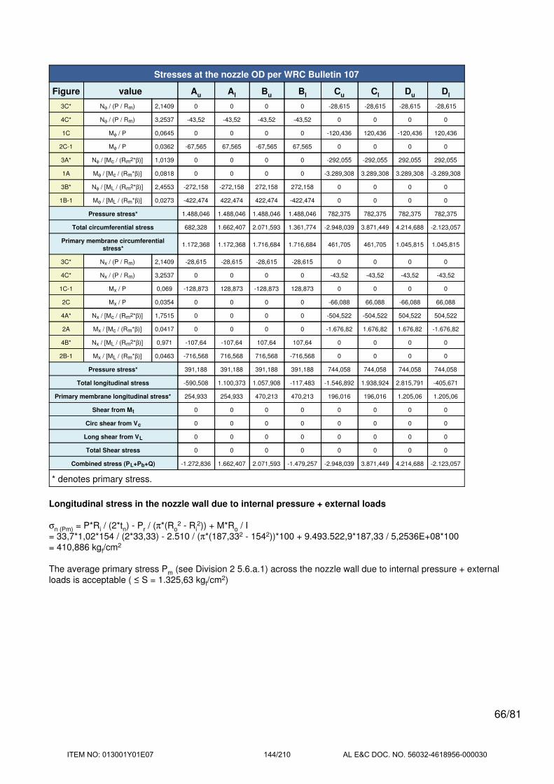
Stresses at the nozzle OD per WRC Bulletin 107
Figure value Au Al Bu Bl Cu Cl Du Dl
3C* Nφ / (P / Rm) 2,1409 0 0 0 0 -28,615 -28,615 -28,615 -28,615
4C* Nφ / (P / Rm) 3,2537 -43,52 -43,52 -43,52 -43,52 0 0 0 0
1C Mφ / P 0,0645 0 0 0 0 -120,436 120,436 -120,436 120,436
2C-1 Mφ / P 0,0362 -67,565 67,565 -67,565 67,565 0 0 0 0
3A* Nφ / [Mc / (Rm2*β)] 1,0139 0 0 0 0 -292,055 -292,055 292,055 292,055
1A Mφ / [Mc / (Rm*β)] 0,0818 0 0 0 0 -3.289,308 3.289,308 3.289,308 -3.289,308
3B* Nφ / [ML / (Rm2*β)] 2,4553 -272,158 -272,158 272,158 272,158 0 0 0 0
1B-1 Mφ / [ML / (Rm*β)] 0,0273 -422,474 422,474 422,474 -422,474 0 0 0 0
Pressure stress* 1.488,046 1.488,046 1.488,046 1.488,046 782,375 782,375 782,375 782,375
Total circumferential stress 682,328 1.662,407 2.071,593 1.361,774 -2.948,039 3.871,449 4.214,688 -2.123,057
Primary membrane circumferential
stress*1.172,368 1.172,368 1.716,684 1.716,684 461,705 461,705 1.045,815 1.045,815
3C* Nx / (P / Rm) 2,1409 -28,615 -28,615 -28,615 -28,615 0 0 0 0
4C* Nx / (P / Rm) 3,2537 0 0 0 0 -43,52 -43,52 -43,52 -43,52
1C-1 Mx / P 0,069 -128,873 128,873 -128,873 128,873 0 0 0 0
2C Mx / P 0,0354 0 0 0 0 -66,088 66,088 -66,088 66,088
4A* Nx / [Mc / (Rm2*β)] 1,7515 0 0 0 0 -504,522 -504,522 504,522 504,522
2A Mx / [Mc / (Rm*β)] 0,0417 0 0 0 0 -1.676,82 1.676,82 1.676,82 -1.676,82
4B* Nx / [ML / (Rm2*β)] 0,971 -107,64 -107,64 107,64 107,64 0 0 0 0
2B-1 Mx / [ML / (Rm*β)] 0,0463 -716,568 716,568 716,568 -716,568 0 0 0 0
Pressure stress* 391,188 391,188 391,188 391,188 744,058 744,058 744,058 744,058
Total longitudinal stress -590,508 1.100,373 1.057,908 -117,483 -1.546,892 1.938,924 2.815,791 -405,671
Primary membrane longitudinal stress* 254,933 254,933 470,213 470,213 196,016 196,016 1.205,06 1.205,06
Shear from Mt 0 0 0 0 0 0 0 0
Circ shear from Vc 0 0 0 0 0 0 0 0
Long shear from VL 0 0 0 0 0 0 0 0
Total Shear stress 0 0 0 0 0 0 0 0
Combined stress (PL+Pb+Q) -1.272,836 1.662,407 2.071,593 -1.479,257 -2.948,039 3.871,449 4.214,688 -2.123,057
* denotes primary stress.
Longitudinal stress in the nozzle wall due to internal pressure + external loads
σn (Pm) = P*Ri / (2*tn) - Pr / (π*(Ro2 - Ri
2)) + M*Ro / I
= 33,7*1,02*154 / (2*33,33) - 2.510 / (π*(187,332 - 1542))*100 + 9.493.522,9*187,33 / 5,2536E+08*100
= 410,886 kgf/cm2
The average primary stress Pm (see Division 2 5.6.a.1) across the nozzle wall due to internal pressure + external
loads is acceptable ( ≤ S = 1.325,63 kgf/cm2)
66/81
ITEM NO: 013001Y01E07 144/210 AL E&C DOC. NO. 56032-4618956-000030

Reinforcement Calculations for MAP
Available reinforcement per UG-37 governs the MAP of this nozzle.
UG-37 Area Calculation Summary (cm2)UG-45
Summary(mm)
For P = 48,11 bar @ 20 °C
The opening is adequately reinforced
The nozzle
passes UG-45
A
required
A
availableA1 A2 A3 A5
A
weldstreq tmin
67,0404 67,0418 25,0283 41,258 -- -- 0,7555 9,55 34,93
UG-41 Weld Failure Path Analysis Summary
The nozzle is exempt from weld strength calculations per UW-15(b)(1)
UW-16 Weld Sizing Summary
Weld descriptionRequired weld
throat size (mm)
Actual weld
throat size (mm)Status
Nozzle to shell fillet (Leg41) 6 6,3 weld size is adequate
Calculations for internal pressure 48,11 bar @ 20 °C
Parallel Limit of reinforcement per UG-40
LR = MAX(d, Rn + (tn - Cn) + (t - C))
= MAX(304,8, 152,4 + (34,93 - 0) + (30 - 0))
= 304,8 mm
Outer Normal Limit of reinforcement per UG-40
LH = MIN(2,5*(t - C), 2,5*(tn - Cn) + te)
= MIN(2,5*(30 - 0), 2,5*(34,93 - 0) + 0)
= 75 mm
Nozzle required thickness per UG-27(c)(1)
trn = P*Rn / (Sn*E - 0,6*P)
= 48,1074*152,4 / (1.380*1 - 0,6*48,1074)
= 5,43 mm
Required thickness tr from UG-37(a)
tr = P*Ro / (S*E + 0,4*P)
= 48,1074*675 / (1.480*1 + 0,4*48,1074)
= 21,66 mm
67/81
ITEM NO: 013001Y01E07 145/210 AL E&C DOC. NO. 56032-4618956-000030

Area required per UG-37(c)
Allowable stresses: Sn = 1.407,207, Sv = 1.509,179 kgf/cm2
fr1 = lesser of 1 or Sn / Sv = 0,9324
fr2 = lesser of 1 or Sn / Sv = 0,9324
A = d*tr*F + 2*tn*tr*F*(1 - fr1)
= (304,8*21,66*1 + 2*34,93*21,66*1*(1 - 0,9324)) / 100
= 67,0404 cm2
Area available from FIG. UG-37.1
A1 = larger of the following= 25,0283 cm2
= d*(E1*t - F*tr) - 2*tn*(E1*t - F*tr)*(1 - fr1)
= (304,8*(1*30 - 1*21,66) - 2*34,93*(1*30 - 1*21,66)*(1 - 0,9324)) / 100
= 25,0283 cm2
= 2*(t + tn)*(E1*t - F*tr) - 2*tn*(E1*t - F*tr)*(1 - fr1)
= (2*(30 + 34,93)*(1*30 - 1*21,66) - 2*34,93*(1*30 - 1*21,66)*(1 - 0,9324)) / 100
= 10,4368 cm2
A2 = smaller of the following= 41,258 cm2
= 5*(tn - trn)*fr2*t
= (5*(34,93 - 5,43)*0,9324*30) / 100
= 41,258 cm2
= 5*(tn - trn)*fr2*tn= (5*(34,93 - 5,43)*0,9324*34,93) / 100
= 48,0315 cm2
A41 = Leg2*fr2= (92*0,9324) / 100
= 0,7555 cm2
Area = A1 + A2 + A41
= 25,0283 + 41,258 + 0,7555
= 67,0418 cm2
As Area >= A the reinforcement is adequate.
68/81
ITEM NO: 013001Y01E07 146/210 AL E&C DOC. NO. 56032-4618956-000030

UW-16(c) Weld Check
Fillet weld: tmin = lesser of 19 mm or tn or t = 19 mm
tc(min) = lesser of 6 mm or 0,7*tmin = 6 mm
tc(actual) = 0,7*Leg = 0.7*9 = 6,3 mm
The fillet weld size is satisfactory.
Weld strength calculations are not required for this detail which conforms to Fig. UW-16.1, sketch (c-e).
UG-45 Nozzle Neck Thickness Check
ta UG-27 = P*Rn / (Sn*E - 0,6*P) + Corrosion
= 48,1074*152,4 / (1.380*1 - 0,6*48,1074) + 0
= 5,43 mm
ta UG-22 = 9,55 mm
ta = max[ ta UG-27 , ta UG-22 ]
= max[ 5,43 , 9,55 ]
= 9,55 mm
tb1 = P*Ro / (S*E + 0,4*P) + Corrosion
= 48,1074*675 / (1.480*1 + 0,4*48,1074) + 0
= 21,66 mm
tb1 = max[ tb1 , tb UG16 ]
= max[ 21,66 , 1,5 ]
= 21,66 mm
tb = min[ tb3 , tb1 ]
= min[ 8,33 , 21,66 ]
= 8,33 mm
tUG-45 = max[ ta , tb ]
= max[ 9,55 , 8,33 ]
= 9,55 mm
Available nozzle wall thickness new, tn = 34,93 mm
The nozzle neck thickness is adequate.
69/81
ITEM NO: 013001Y01E07 147/210 AL E&C DOC. NO. 56032-4618956-000030

Ellipsoidal Head Outlet
ASME Section VIII Division 1, 2013 Edition Metric
Component Ellipsoidal Head
Material SA-387 11 2 (II-D Metric p. 38, ln. 33)
Attached To Shell Outlet Chamber
ImpactTested
NormalizedFine GrainPractice
PWHTOptimize MDMT/
Find MAWP
Yes (-20°C) Yes No Yes No
DesignPressure (bar)
DesignTemperature (°C)
DesignMDMT (°C)
Internal 30 450 -5,4
Static Liquid Head
Condition Ps (bar) Hs (mm) SG
Test horizontal 0,16 1.655 1
Dimensions
Outer Diameter 1.350 mm
Head Ratio 2
Minimum Thickness 20 mm
CorrosionInner 1,6 mm
Outer 0 mm
Length Lsf 50,8 mm
Nominal Thickness tsf 20 mm
Weight and Capacity
Weight (kg)1 Capacity (liters)1
New 342,3 362,74
Corroded 315,83 365,96
Radiography
Category A joints Seamless No RT
Head to shell seam Full UW-11(a) Type 11 includes straight flange
70/81
ITEM NO: 013001Y01E07 148/210 AL E&C DOC. NO. 56032-4618956-000030

Results Summary
Governing condition internal pressure
Minimum thickness per UG-16 1,5 mm + 1,6 mm = 3,1 mm
Design thickness due to internal pressure (t) 15,46 mm
Maximum allowable working pressure (MAWP) 40,09 bar
Maximum allowable pressure (MAP) 45,05 bar
Straight Flange governs MDMT -34,7°C
Factor K
K = (1/6)*[2 + (D / (2*h))2]
Corroded K = (1/6)*[2 + (1.313,2 / (2*329,1))2] 0,9968
New K = (1/6)*[2 + (1.310 / (2*327,5))2] 1
Design thickness for internal pressure, (Corroded at 450 °C) Appendix 1-4(c)
t = P*Do*K / (2*S*E + 2*P*(K - 0,1)) + Corrosion
= 30*1.350*0,996762 / (2*1.430*1 + 2*30*(0,996762 - 0,1)) + 1,6
= 15,45 mm
Maximum allowable working pressure, (Corroded at 450 °C) Appendix 1-4(c)
P = 2*S*E*t / (K*Do - 2*t*(K - 0,1)) - Ps
= 2*1.430*1*18,4 / (0,996762*1.350 - 2*18,4*(0,996762 - 0,1)) - 0
= 40,09 bar
Maximum allowable pressure, (New at 20 °C) Appendix 1-4(c)
P = 2*S*E*t / (K*Do - 2*t*(K - 0,1)) - Ps
= 2*1.480*1*20 / (1*1.350 - 2*20*(1 - 0,1)) - 0
= 45,05 bar
% Extreme fiber elongation - UCS-79(d)
EFE = (75*t / Rf)*(1 - Rf / Ro)
= (75*20 / 232,7)*(1 - 232,7 / infinity)
= 6,4461%
71/81
ITEM NO: 013001Y01E07 149/210 AL E&C DOC. NO. 56032-4618956-000030

Straight Flange on Ellipsoidal Head Outlet
ASME Section VIII Division 1, 2013 Edition Metric
Component Cylinder
Material SA-387 11 2 (II-D Metric p. 38, ln. 33)
ImpactTested
NormalizedFine GrainPractice
PWHTOptimize MDMT/
Find MAWP
Yes (-20°C) Yes No Yes No
DesignPressure (bar)
DesignTemperature (°C)
DesignMDMT (°C)
Internal 30 450 -5,4
Static Liquid Head
Condition Ps (bar) Hs (mm) SG
Test horizontal 0,16 1.655 1
Dimensions
Outer Diameter 1.350 mm
Length 50,8 mm
Nominal Thickness 20 mm
CorrosionInner 1,6 mm
Outer 0 mm
Weight and Capacity
Weight (kg) Capacity (liters)
New 33,25 68,47
Corroded 30,63 68,8
Radiography
Longitudinal seam Seamless No RT
Left Circumferentialseam
Full UW-11(a) Type 1
72/81
ITEM NO: 013001Y01E07 150/210 AL E&C DOC. NO. 56032-4618956-000030

Results Summary
Governing condition Internal pressure
Minimum thickness per UG-16 1,5 mm + 1,6 mm = 3,1 mm
Design thickness due to internal pressure (t) 15,64 mm
Maximum allowable working pressure (MAWP) 39,41 bar
Maximum allowable pressure (MAP) 44,38 bar
Rated MDMT -34,7 °C
UCS-66 Material Toughness Requirements
Material impact test temperature per UG-84 = -20°C
tr = 30*675 / (1.480*1 + 0.4*30) = 13,57 mm
Stress ratio = tr*E* / (tn - c) = 13,57*1 / (20 - 1,6) = 0,7376
UCS-66(i) reduction in MDMT, TR from Fig UCS-66.1M = 14,7°C
MDMT = max[Timpact - TR, -105] = max[ -20 - 14,7 , -105] = -34,7°C
Design MDMT of -5,4°C is acceptable.
Design thickness, (at 450 °C) Appendix 1-1
t = P*Ro / (S*E + 0,40*P) + Corrosion
= 30*675 / (1.430*1,00 + 0,40*30) + 1,6
= 15,64 mm
Maximum allowable working pressure, (at 450 °C) Appendix 1-1
P = S*E*t / (Ro - 0,40*t) - Ps
= 1.430*1,00*18,4 / (675 - 0,40*18,4) - 0
= 39,41 bar
Maximum allowable pressure, (at 20 °C) Appendix 1-1
P = S*E*t / (Ro - 0,40*t)
= 1.480*1,00*20 / (675 - 0,40*20)
= 44,38 bar
% Extreme fiber elongation - UCS-79(d)
EFE = (50*t / Rf)*(1 - Rf / Ro)
= (50*20 / 665)*(1 - 665 / infinity)
= 1,5038%
The extreme fiber elongation does not exceed 5%.
73/81
ITEM NO: 013001Y01E07 151/210 AL E&C DOC. NO. 56032-4618956-000030

Nozzle (Control Valve)
ASME Section VIII Division 1, 2013 Edition Metric
Note: round inside edges per UG-76(c)
Note: Thread engagement shall comply with the requirements of UG-43(g).
Location and Orientation
Located on Ellipsoidal Head Outlet
Orientation 0°
End of nozzle to datum line 3.573,4 mm
Calculated as hillside No
Distance to head center, R 0 mm
Passes through a Category A joint No
Nozzle
Access opening No
Material specification SA-182 F11 2 (II-D Metric p. 38, ln. 30) (normalized)
Bolt material specification SA-193 B7 Bolt <= 64 (II-D Metric p. 352, ln. 31)
Bolt rated MDMT -48°C
Pad inner diameter 170 mm
Pad outer diameter, Dp 320 mm
Pad thickness 75 mm
Figure UG-40 thickness, te 55 mm
Tapped hole diameter 27 mm
Tapped hole depth 46 mm
Tapped hole bolt circle 255 mm
Raised face height 0 mm
Raised face outer diameter 320 mm
74/81
ITEM NO: 013001Y01E07 152/210 AL E&C DOC. NO. 56032-4618956-000030
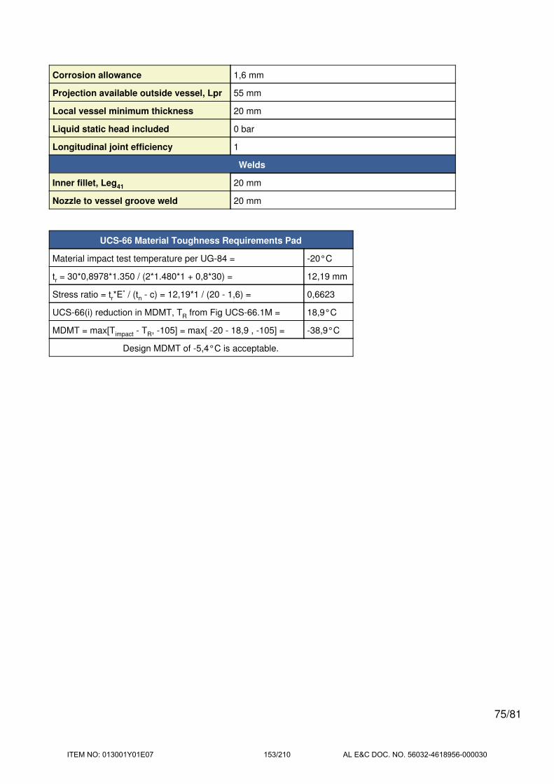
Corrosion allowance 1,6 mm
Projection available outside vessel, Lpr 55 mm
Local vessel minimum thickness 20 mm
Liquid static head included 0 bar
Longitudinal joint efficiency 1
Welds
Inner fillet, Leg41 20 mm
Nozzle to vessel groove weld 20 mm
UCS-66 Material Toughness Requirements Pad
Material impact test temperature per UG-84 = -20°C
tr = 30*0,8978*1.350 / (2*1.480*1 + 0,8*30) = 12,19 mm
Stress ratio = tr*E* / (tn - c) = 12,19*1 / (20 - 1,6) = 0,6623
UCS-66(i) reduction in MDMT, TR from Fig UCS-66.1M = 18,9°C
MDMT = max[Timpact - TR, -105] = max[ -20 - 18,9 , -105] = -38,9°C
Design MDMT of -5,4°C is acceptable.
75/81
ITEM NO: 013001Y01E07 153/210 AL E&C DOC. NO. 56032-4618956-000030

Reinforcement Calculations for MAWP
The vessel wall thickness governs the MAWP of this nozzle.
UG-37 Area Calculation Summary (cm2)UG-45
Summary(mm)
For P = 43,95 bar @ 450 °C
The opening is adequately reinforced
The nozzle
passes UG-45
A
required
A
availableA1 A2 A3 A5
A
weldstreq tmin
54,3034 64,6052 -- -- -- 61,389 3,2161 9,93 75
UG-41 Weld Failure Path Analysis Summary
The nozzle is exempt from weld strength calculations per UW-15(b)(1)
UW-16 Weld Sizing Summary
Weld descriptionRequired weld
throat size (mm)
Actual weld
throat size (mm)Status
Pad to shell fillet (Leg41) 6 14 weld size is adequate
Calculations for internal pressure 43,95 bar @ 450 °C
Parallel Limit of reinforcement per UG-40
LR = MAX(d, Rn + (tn - Cn) + (t - C))
= MAX(173,2, 86,6 + (0) + (20 - 1,6))
= 173,2 mm
Outer Normal Limit of reinforcement per UG-40
LH = MIN(2,5*(t - C), 2,5*(tn - Cn) + te)
= MIN(2,5*(20 - 1,6), 2,5*(0) + 55)
= 46 mm
Required thickness tr from UG-37(a)(c)
tr = P*K1*Do / (2*S*E + 0,8*P)
= 43,9515*0,8978*1.350 / (2*1.430*1 + 0,8*43,9515)
= 18,4 mm
Required thickness tr per Interpretation VIII-1-07-50
tr = P*Do*K / (2*S*E + 2*P*(K - 0,1))
= 43,95*1.350*0,996762 / (2*1.430*1 + 2*43,95*(0,996762 - 0,1))
= 20,12 mm
76/81
ITEM NO: 013001Y01E07 154/210 AL E&C DOC. NO. 56032-4618956-000030

Area required per UG-37(c)
Allowable stresses: Sn = 1.325,63, Sv = 1.458,193, Sp = 1.325,63 kgf/cm2
fr1 = lesser of 1 or Sn / Sv = 0,9091
fr2 = lesser of 1 or Sn / Sv = 0,9091
fr4 = lesser of 1 or Sp / Sv = 0,9091
A = d*tr*F + 2*tn*tr*F*(1 - fr1) + Tapped hole area loss
= (173,2*18,4*1 + 2*73,4*18,4*1*(1 - 0,9091)) / 100 + 19,9797
= 54,3034 cm2
Area available from FIG. UG-37.1
A1 = larger of the following= 0 cm2
= d*(E1*t - F*tr) - 2*tn*(E1*t - F*tr)*(1 - fr1)
= (173,2*(1*18,4 - 1*18,4) - 2*73,4*(1*18,4 - 1*18,4)*(1 - 0,9091)) / 100
= 0 cm2
= 2*(t + tn)*(E1*t - F*tr) - 2*tn*(E1*t - F*tr)*(1 - fr1)
= (2*(18,4 + 0)*(1*18,4 - 1*18,4) - 2*73,4*(1*18,4 - 1*18,4)*(1 - 0,9091)) / 100
= 0 cm2
Area A2 is not included in these calculations.
A42 = Leg2*fr4= (18,812*0,9091) / 100
= 3,2161 cm2
(Part of the weld is outside of the limits)
A5 = (Dp - Pad ID)*te*fr4= ((320 - 173,2)*46*0,9091) / 100
= 61,389 cm2
Area = A1 + A42 + A5
= 0 + 3,2161 + 61,389
= 64,6052 cm2
As Area >= A the reinforcement is adequate.
UW-16(c) Weld Check
Fillet weld: tmin = lesser of 19 mm or te or t = 18,4 mm
tc(min) = lesser of 6 mm or 0,7*tmin = 6 mm
77/81
ITEM NO: 013001Y01E07 155/210 AL E&C DOC. NO. 56032-4618956-000030

tc(actual) = 0,7*Leg = 0.7*20 = 14 mm
The fillet weld size is satisfactory.
Weld strength calculations are not required for this detail which conforms to Fig. UW-16.1, sketch (c-e).
UG-45 Nozzle Neck Thickness Check
Interpretation VIII-1-83-66 has been applied.
ta UG-27 = P*Rn / (Sn*E - 0,6*P) + Corrosion
= 43,9515*86,6 / (1.300*1 - 0,6*43,9515) + 1,6
= 4,59 mm
ta = max[ ta UG-27 , ta UG-22 ]
= max[ 4,59 , 0 ]
= 4,59 mm
tb1 = 21,72 mm
tb1 = max[ tb1 , tb UG16 ]
= max[ 21,72 , 3,1 ]
= 21,72 mm
tb = min[ tb3 , tb1 ]
= min[ 9,93 , 21,72 ]
= 9,93 mm
tUG-45 = max[ ta , tb ]
= max[ 4,59 , 9,93 ]
= 9,93 mm
Available nozzle wall thickness new, tn = 75 mm
The nozzle neck thickness is adequate.
78/81
ITEM NO: 013001Y01E07 156/210 AL E&C DOC. NO. 56032-4618956-000030
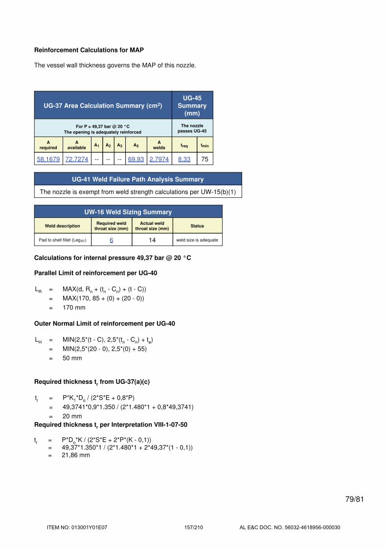
Reinforcement Calculations for MAP
The vessel wall thickness governs the MAP of this nozzle.
UG-37 Area Calculation Summary (cm2)UG-45
Summary(mm)
For P = 49,37 bar @ 20 °C
The opening is adequately reinforced
The nozzle
passes UG-45
A
required
A
availableA1 A2 A3 A5
A
weldstreq tmin
58,1679 72,7274 -- -- -- 69,93 2,7974 8,33 75
UG-41 Weld Failure Path Analysis Summary
The nozzle is exempt from weld strength calculations per UW-15(b)(1)
UW-16 Weld Sizing Summary
Weld descriptionRequired weld
throat size (mm)
Actual weld
throat size (mm)Status
Pad to shell fillet (Leg41) 6 14 weld size is adequate
Calculations for internal pressure 49,37 bar @ 20 °C
Parallel Limit of reinforcement per UG-40
LR = MAX(d, Rn + (tn - Cn) + (t - C))
= MAX(170, 85 + (0) + (20 - 0))
= 170 mm
Outer Normal Limit of reinforcement per UG-40
LH = MIN(2,5*(t - C), 2,5*(tn - Cn) + te)
= MIN(2,5*(20 - 0), 2,5*(0) + 55)
= 50 mm
Required thickness tr from UG-37(a)(c)
tr = P*K1*Do / (2*S*E + 0,8*P)
= 49,3741*0,9*1.350 / (2*1.480*1 + 0,8*49,3741)
= 20 mm
Required thickness tr per Interpretation VIII-1-07-50
tr = P*Do*K / (2*S*E + 2*P*(K - 0,1))
= 49,37*1.350*1 / (2*1.480*1 + 2*49,37*(1 - 0,1))
= 21,86 mm
79/81
ITEM NO: 013001Y01E07 157/210 AL E&C DOC. NO. 56032-4618956-000030

Area required per UG-37(c)
Allowable stresses: Sn = 1.407,207, Sv = 1.509,179, Sp = 1.407,207 kgf/cm2
fr1 = lesser of 1 or Sn / Sv = 0,9324
fr2 = lesser of 1 or Sn / Sv = 0,9324
fr4 = lesser of 1 or Sp / Sv = 0,9324
A = d*tr*F + 2*tn*tr*F*(1 - fr1) + Tapped hole area loss
= (170*20*1 + 2*75*20*1*(1 - 0,9324)) / 100 + 22,14
= 58,1679 cm2
Area available from FIG. UG-37.1
A1 = larger of the following= 0 cm2
= d*(E1*t - F*tr) - 2*tn*(E1*t - F*tr)*(1 - fr1)
= (170*(1*20 - 1*20) - 2*75*(1*20 - 1*20)*(1 - 0,9324)) / 100
= 0 cm2
= 2*(t + tn)*(E1*t - F*tr) - 2*tn*(E1*t - F*tr)*(1 - fr1)
= (2*(20 + 0)*(1*20 - 1*20) - 2*75*(1*20 - 1*20)*(1 - 0,9324)) / 100
= 0 cm2
Area A2 is not included in these calculations.
A42 = Leg2*fr4= (17,322*0,9324) / 100
= 2,7974 cm2
(Part of the weld is outside of the limits)
A5 = (Dp - Pad ID)*te*fr4= ((320 - 170)*50*0,9324) / 100
= 69,93 cm2
Area = A1 + A42 + A5
= 0 + 2,7974 + 69,93
= 72,7274 cm2
As Area >= A the reinforcement is adequate.
UW-16(c) Weld Check
Fillet weld: tmin = lesser of 19 mm or te or t = 19 mm
tc(min) = lesser of 6 mm or 0,7*tmin = 6 mm
80/81
ITEM NO: 013001Y01E07 158/210 AL E&C DOC. NO. 56032-4618956-000030

tc(actual) = 0,7*Leg = 0.7*20 = 14 mm
The fillet weld size is satisfactory.
Weld strength calculations are not required for this detail which conforms to Fig. UW-16.1, sketch (c-e).
UG-45 Nozzle Neck Thickness Check
Interpretation VIII-1-83-66 has been applied.
ta UG-27 = P*Rn / (Sn*E - 0,6*P) + Corrosion
= 49,3741*85 / (1.380*1 - 0,6*49,3741) + 0
= 3,11 mm
ta = max[ ta UG-27 , ta UG-22 ]
= max[ 3,11 , 0 ]
= 3,11 mm
tb1 = 21,86 mm
tb1 = max[ tb1 , tb UG16 ]
= max[ 21,86 , 1,5 ]
= 21,86 mm
tb = min[ tb3 , tb1 ]
= min[ 8,33 , 21,86 ]
= 8,33 mm
tUG-45 = max[ ta , tb ]
= max[ 3,11 , 8,33 ]
= 8,33 mm
Available nozzle wall thickness new, tn = 75 mm
The nozzle neck thickness is adequate.
81/81
ITEM NO: 013001Y01E07 159/210 AL E&C DOC. NO. 56032-4618956-000030

Structural calculation
Process Gas Boiler Axion_Campana J160165DA for
Bertsch Energy Ges.m.b.H&Co.KG Herrengasse 23 A-6700 Bludenz
Processed by: Dipl. Ing. E. Schöpf Eccon Ges.m.b.H Industriestrraße 8 A-6832 Sulz
Date: 1.February 2017
Signature:
Remarks:
ITEM NO: 013001Y01E07 160/210 AL E&C DOC. NO. 56032-4618956-000030
1 DESCRIPTION: 3
2 MATERIAL: 7
3 LOADS: 10
4 RESULTS: 14
4.1 Load case 8: Test pressure water side 42bar*1.3=54.6bar 15
4.2 Load case 9: Test pressure gas side 30bar*1.38=41.35bar 22
4.3 Load cases 10 to 14: Pressure 42bar/30bar + Temp 32
4.4 Load cases 15 to 19: Pressure 42bar/-1bar + Temp 37
4.1 Load cases 20 to 24: Pressure -1bar/30bar + Temp 42
5 WELDING DETAILS HEATING TUBE AND BYPASS TUBE: 47
ITEM NO: 013001Y01E07 161/210 AL E&C DOC. NO. 56032-4618956-000030

1 Description:
A FE calculation is carried out for the “Process Gas Boiler” comprising the following parts according PG-16.1:
Jacket tube Inlet plate Heating surface tubes Bypass tubes Outlet plate
This division of Section VIII-1 does not contain rules to cover the design and construction. The design of this point is checked under consideration of U-2(g) by a finite element analysis. This needs the acceptance of the AI.
The calculation is carried out on a 180-degree sector taking symmetry into account with the help of peripheral conditions. The load is applied through the internal pressure in the jacket space (water side) and the pressure in the gas space as well as by initial expansions due to the various temperatures.
The heating surface tubes as well as the bypass tubes are welded to the inlet plate and outlet plate at the walls of the drilled holes in the plates.
The temperatures in the structure are taken as defined by customer.
The heating surface tubes and bypass tubes have the following nominal dimensions
heating surface 33.4 * 3.38 mm bypass tubes 73.0 * 7.01 mm
Calculation is done for reduced wall thickness because of corrosion. The values for the reduction of wall thickness are: heating tubes 0.0 mm bypass tube 0.0 mm Jacket tube 1.6 mm jacket tube at gas outlet 1.6 mm jacket tube at gas inlet 1.6 mm tube sheets 3.2 mm
Allowable Stresses for FEM:
Section I defines in PG-23 that the allowable stress values from Section II, Part D, tables 1A and 1B have to be used for the equations given in Section I. Even the preamble and PG-16.1 define under the restrictions given in PG-16.1 that alternative methods can be used but does not show specific limits.
ITEM NO: 013001Y01E07 162/210 AL E&C DOC. NO. 56032-4618956-000030

To fulfil the requirements of Section I, especially the preamble and PG-16.1, to calculate as safe as the rules of Section I the limits for the allowable stresses will be defined equal to ASME VIII-1, UG-23. Because VIII-1 uses also the allowable stresses from Section II, Part D, tables 1A und 1B.
Additionally, to the limits of UG-23 the maximum allowable membrane stress values for test conditions shall not exceed 90% of yield strength as given in Section II, Part D.
The linear elastic calculation is carried out with the finite element program FENAS. Bar elements and shell elements are employed. The program was developed at the Imperial College in London. For this calculation hybrid finite elements are used. The program is intended for linear elastic calculations as well as nonlinear calculations for bar-elements, shell-elements and solids.
Computer program verification:
Computer programs have been used to prepare this design calculation. Each program module used to prepare this design calculation was verified prior to use for the applicable standard. A verification report was prepared and approved. The verification report and evidence of verification are available to the AI upon request.
ITEM NO: 013001Y01E07 163/210 AL E&C DOC. NO. 56032-4618956-000030

ITEM NO: 013001Y01E07 164/210 AL E&C DOC. NO. 56032-4618956-000030

ITEM NO: 013001Y01E07 165/210 AL E&C DOC. NO. 56032-4618956-000030

2 Material:
Following materials are used:
SA-387 11 2 jacket tube SA-182 F11 2 tube sheets for inlet and outlet SA 335 P11 heating surface and bypass tubes
with the following material values:
Modulus of elasticity (at temperature 300C) 192 000 N/mm2
Poisson’s ratio 0.3 Thermal expansion coefficient 12. 10-6 m/m C
SA-387 Gr.11 Cl.2 jacket tube Yield limit (20C) 310 N/mm2
ASME allowable (260C) 148 N/mm2
SA-182 F.11 2 inlet plate and outlet plate Yield limit (20C) 276 N/mm2
ASME allowable (310C) inlet 138 N/mm2
SA 335 P11 heating surface and bypass tubes Yield limit (20C) 207 N/mm2
ASME allowable (310C) 108 N/mm2
The material behaviour is linear elastic.
ITEM NO: 013001Y01E07 166/210 AL E&C DOC. NO. 56032-4618956-000030

ITEM NO: 013001Y01E07 167/210 AL E&C DOC. NO. 56032-4618956-000030

ITEM NO: 013001Y01E07 168/210 AL E&C DOC. NO. 56032-4618956-000030

3 Loads:
The calculation is carried out for pressure and temperature loads in separate load cases. The result of the overall load is calculated by way of superimposing the load cases.
Load case 1: Design pressure water side 42bar
A pressure of 42bar against the surroundings prevails in the jacket space, the pressure in the heating surface tubes and bypass tubes corresponds to the surrounding pressure.
Load case 2: Design pressure gas side 30bar
A pressure of 30bar against the surroundings prevails in the heating surface tubes and bypass tubes as well as in the inlet and outlet chambers. The pressure in the jacket space (water side) corresponds to the surrounding pressure.
Load cases 3-7: Temperature load cases:
All components are given initial expansions which are proportional to the temperatures as defined by customer.
ITEM NO: 013001Y01E07 169/210 AL E&C DOC. NO. 56032-4618956-000030

ITEM NO: 013001Y01E07 170/210 AL E&C DOC. NO. 56032-4618956-000030

ITEM NO: 013001Y01E07 171/210 AL E&C DOC. NO. 56032-4618956-000030

ITEM NO: 013001Y01E07 172/210 AL E&C DOC. NO. 56032-4618956-000030

4 Results:
In order to be able to evaluate the calculation results according to the ASME the membrane stresses and the maximum comparison stresses are output separately for all operating load cases, test pressures and special load cases. All shell stresses are shown on the deformed structure with deformations increased 50 times. Under the title “equivalent stress” the comparison stresses according to Mises in the central plane of the finite elements (membrane stress component) are shown. The stress “max.equivalent stress” shows the resultant comparison stress on the outer fibre of the elements and constitutes the more unfavourable value of element top or bottom. These stresses show the superposition of membrane stresses and plate bending.
For the in-service loads and the special load cases only the load combinations showing the highest stresses are printed here. The following load cases are evaluated:
Load case
8 Test pressure water side 42bar*1.3 = 54.6 bar
9 Test pressure gas side 30bar*1.38 = 41.35 bar
10 to 14 Water side 42bar, gas side 30bar, temp
15 to 19 Water side 42bar, gas side -1bar, temp
20 to 24 Water side -1bar, gas side 30bar, temp
load cases 8 and 9 each constitute the one-sided test pressures load cases 10 to 14 are the standard operating load cases load cases 15 to 24 are malfunctions with total drop of pressure at water side or gas side and require the shut down of the boiler.
ITEM NO: 013001Y01E07 173/210 AL E&C DOC. NO. 56032-4618956-000030

4.1 Load case 8: Test pressure water side 42bar*1.3=54.6bar
In addition to the stresses in the shell elements, the longitudinal stress is shown for the heating tubes and for the bypass tubes. The allowable primary stresses for test pressure are acc. to ASME section VIII-1, UG-23. The allowable membrane stress values for test conditions shall not exceed 90% of yield strength as given in Section II, Part D.
Temperature yield Strength allowable Pm 0.9*yield
allowable Pl+Pb 0.9*yield*1.5
inlet and outlet plate 20ºC 276 N/mm2 248 N/mm2 373 N/mm2
Heating tubes and bypass tube
20ºC 207 N/mm2 186 N/mm2 279 N/mm2
Jacket tubes 20°C 310 N/mm2 279 N/mm2 419 N/mm2
The actual stresses in the components are calculated as:
Component Pm Pl and Pb
Inlet plate 40 N/mm2 233 N/mm2
outlet plate 35 N/mm2 232 N/mm2
Heating tubes 101 N/mm2 180 N/mm2
bypass tubes 91 N/mm2 214 N/mm2
jacket tube 147 N/mm2 255 N/mm2
All stresses are within the allowable limits.
ITEM NO: 013001Y01E07 174/210 AL E&C DOC. NO. 56032-4618956-000030

ITEM NO: 013001Y01E07 175/210 AL E&C DOC. NO. 56032-4618956-000030

ITEM NO: 013001Y01E07 176/210 AL E&C DOC. NO. 56032-4618956-000030

ITEM NO: 013001Y01E07 177/210 AL E&C DOC. NO. 56032-4618956-000030

ITEM NO: 013001Y01E07 178/210 AL E&C DOC. NO. 56032-4618956-000030

ITEM NO: 013001Y01E07 179/210 AL E&C DOC. NO. 56032-4618956-000030

ITEM NO: 013001Y01E07 180/210 AL E&C DOC. NO. 56032-4618956-000030

4.2 Load case 9: Test pressure gas side 30bar*1.38=41.35bar
In addition to the stresses in the shell elements, the longitudinal stress is shown for the heating tubes and for the bypass tubes. The allowable primary stresses for test pressure are acc. to ASME section VIII-1, UG-23. The allowable membrane stress values for test conditions shall not exceed 90% of yield strength as given in Section II, Part D.
Temperature yield Strength allowable Pm 0.9*yield
allowable Pl+Pb 0.9*yield*1.5
inlet and outlet plate 20ºC 276 N/mm2 248 N/mm2 373 N/mm2
Heating tubes and bypass tubes
20ºC 207 N/mm2 186 N/mm2 279 N/mm2
Jacket tubes 20°C 310 N/mm2 279 N/mm2 419 N/mm2
The actual stresses in the components are calculated as:
Component Pm Pl and Pb
Inlet plate 53 N/mm2 222 N/mm2
outlet plate 43 N/mm2 217 N/mm2
Heating tubes 87 N/mm2 115 N/mm2
bypass tubes 78 N/mm2 164 N/mm2
jacket tube 87 N/mm2 244 N/mm2
All stresses are within the allowable values.
ITEM NO: 013001Y01E07 181/210 AL E&C DOC. NO. 56032-4618956-000030

Proof of stability is furnished for the heating tube with the greatest compressive stress by means of an FE bar model. With a compressive force of -18.0 KN (normal stress of –56.4 N/mm2) the safety against elastic buckling is calculated as
Safety against elastic buckling = 2.66
Clamping of the tube at both ends in the plates and moment-free support of the tube on the 4 support plates in the shell space is taken into account. In the load case with vacuum in the water space the compressive force is -13.7 KN and the resulting safety against elastic buckling is 3.49.
ITEM NO: 013001Y01E07 182/210 AL E&C DOC. NO. 56032-4618956-000030

ITEM NO: 013001Y01E07 183/210 AL E&C DOC. NO. 56032-4618956-000030

ITEM NO: 013001Y01E07 184/210 AL E&C DOC. NO. 56032-4618956-000030

ITEM NO: 013001Y01E07 185/210 AL E&C DOC. NO. 56032-4618956-000030

ITEM NO: 013001Y01E07 186/210 AL E&C DOC. NO. 56032-4618956-000030

ITEM NO: 013001Y01E07 187/210 AL E&C DOC. NO. 56032-4618956-000030

ITEM NO: 013001Y01E07 188/210 AL E&C DOC. NO. 56032-4618956-000030

ITEM NO: 013001Y01E07 189/210 AL E&C DOC. NO. 56032-4618956-000030

ITEM NO: 013001Y01E07 190/210 AL E&C DOC. NO. 56032-4618956-000030
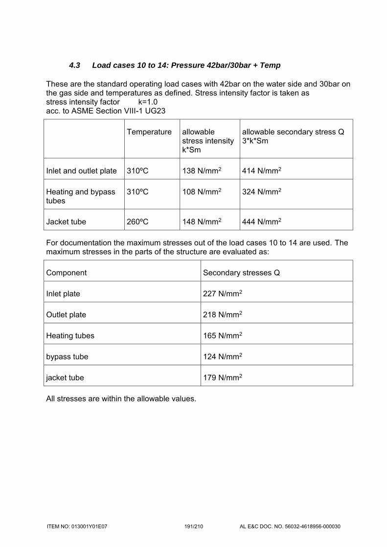
4.3 Load cases 10 to 14: Pressure 42bar/30bar + Temp
These are the standard operating load cases with 42bar on the water side and 30bar on the gas side and temperatures as defined. Stress intensity factor is taken as stress intensity factor k=1.0 acc. to ASME Section VIII-1 UG23
Temperature allowable stress intensity k*Sm
allowable secondary stress Q 3*k*Sm
Inlet and outlet plate 310ºC 138 N/mm2 414 N/mm2
Heating and bypass tubes
310ºC 108 N/mm2 324 N/mm2
Jacket tube 260ºC 148 N/mm2 444 N/mm2
For documentation the maximum stresses out of the load cases 10 to 14 are used. The maximum stresses in the parts of the structure are evaluated as:
Component Secondary stresses Q
Inlet plate 227 N/mm2
Outlet plate 218 N/mm2
Heating tubes 165 N/mm2
bypass tube 124 N/mm2
jacket tube 179 N/mm2
All stresses are within the allowable values.
ITEM NO: 013001Y01E07 191/210 AL E&C DOC. NO. 56032-4618956-000030

ITEM NO: 013001Y01E07 192/210 AL E&C DOC. NO. 56032-4618956-000030

ITEM NO: 013001Y01E07 193/210 AL E&C DOC. NO. 56032-4618956-000030
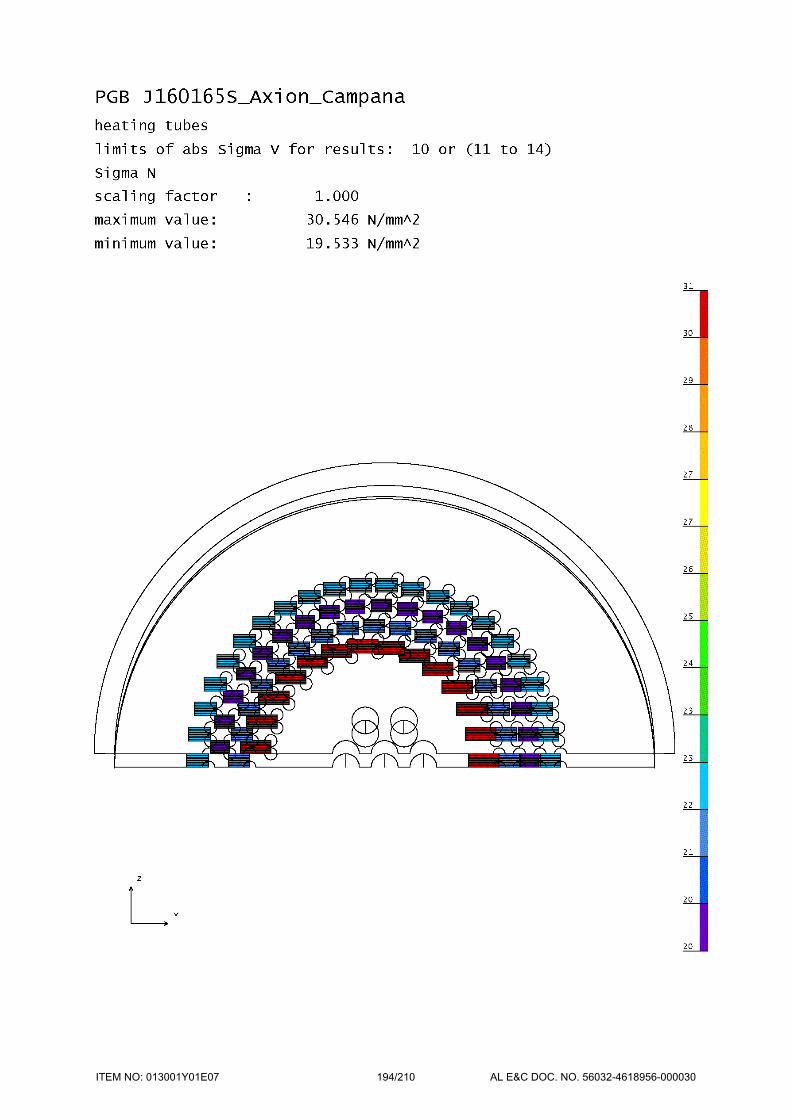
ITEM NO: 013001Y01E07 194/210 AL E&C DOC. NO. 56032-4618956-000030

ITEM NO: 013001Y01E07 195/210 AL E&C DOC. NO. 56032-4618956-000030

4.4 Load cases 15 to 19: Pressure 42bar/-1bar + Temp
This load case with total drop of pressure on the gas side and 42bar on the water side is a malfunction and requires the shut down of the boiler. Stress intensity factor is taken as stress intensity factor k=1.0 acc. to ASME Section VIII-1 UG23
Temperature allowable stress intensity k*Sm
allowable secondary stress Q 3*k*Sm
Inlet and outlet plate 310ºC 138 N/mm2 414 N/mm2
Heating and bypass tubes
310ºC 108 N/mm2 324 N/mm2
Jacket tube 260ºC 148 N/mm2 444 N/mm2
The maximum stresses for load cases 15 to 19 in the parts of the structure are evaluated as:
Component Secondary stresses Q
Inlet plate 217 N/mm2
Outlet plate 219 N/mm2
Heating tubes 192 N/mm2
bypass tube 155 N/mm2
jacket tube 237 N/mm2
All stresses are within the allowable values.
ITEM NO: 013001Y01E07 196/210 AL E&C DOC. NO. 56032-4618956-000030

ITEM NO: 013001Y01E07 197/210 AL E&C DOC. NO. 56032-4618956-000030

ITEM NO: 013001Y01E07 198/210 AL E&C DOC. NO. 56032-4618956-000030

ITEM NO: 013001Y01E07 199/210 AL E&C DOC. NO. 56032-4618956-000030

ITEM NO: 013001Y01E07 200/210 AL E&C DOC. NO. 56032-4618956-000030

4.1 Load cases 20 to 24: Pressure -1bar/30bar + Temp
This load case with total drop of pressure on the gas side and 42bar on the water side is a malfunction and requires the shut down of the boiler. Stress intensity factor is taken as stress intensity factor k=1.0 acc. to ASME Section VIII-1 UG23
Temperature allowable stress intensity k*Sm
allowable secondary stress Q 3*k*Sm
Inlet and outlet plate 310ºC 138 N/mm2 414 N/mm2
Heating and bypass tubes
310ºC 108 N/mm2 324 N/mm2
Jacket tube 260ºC 148 N/mm2 444 N/mm2
The maximum stresses for load cases 15 to 19 in the parts of the structure are evaluated as:
Component Secondary stresses Q
Inlet plate 389 N/mm2
Outlet plate 384 N/mm2
Heating tubes 85 N/mm2
bypass tube 288 N/mm2
jacket tube 142 N/mm2
All stresses are within the allowable values.
ITEM NO: 013001Y01E07 201/210 AL E&C DOC. NO. 56032-4618956-000030

ITEM NO: 013001Y01E07 202/210 AL E&C DOC. NO. 56032-4618956-000030

ITEM NO: 013001Y01E07 203/210 AL E&C DOC. NO. 56032-4618956-000030

ITEM NO: 013001Y01E07 204/210 AL E&C DOC. NO. 56032-4618956-000030

ITEM NO: 013001Y01E07 205/210 AL E&C DOC. NO. 56032-4618956-000030

5 Welding details heating tube and bypass tube:
For the welding details of the heating tubes and the bypass tubes additional axisymmetric FE-calculations are made. The maximum axial loads are taken from the shell-calculation (load case test pressure water side), acting simultaneously with the pressure in the water side of the vessel. The characteristic material strength has to be taken for room temperature.
Temperature yield strength allowable Pm 0.9*yield
allowable Pl+Pb 0.9*yield*1.5
inlet and outlet plate 20ºC 276 N/mm2 248 N/mm2 373 N/mm2
Heating tubes and bypass tubes
20ºC 207 N/mm2 186 N/mm2 279 N/mm2
For test-pressure 54.6bar and axial forces in tubes
axial force
heating surface tube 23.0 KN
bypass tube 84 KN
the following stresses are evaluated:
welding heating tubes 177 N/mm2
welding bypass tube 165 N/mm2
All stresses are within the allowable values.
ITEM NO: 013001Y01E07 206/210 AL E&C DOC. NO. 56032-4618956-000030
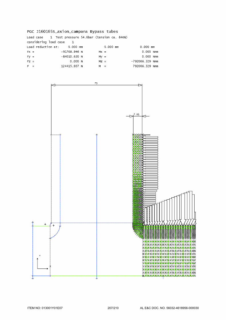
ITEM NO: 013001Y01E07 207/210 AL E&C DOC. NO. 56032-4618956-000030

ITEM NO: 013001Y01E07 208/210 AL E&C DOC. NO. 56032-4618956-000030
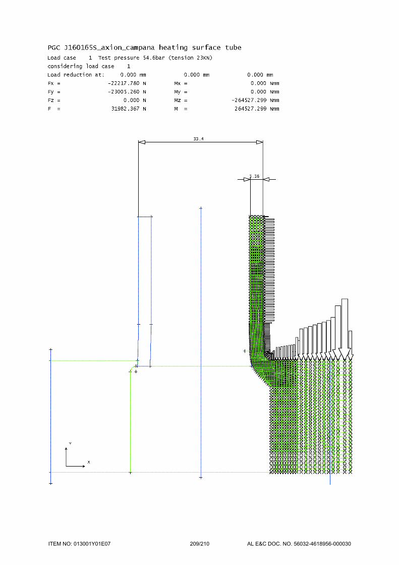
ITEM NO: 013001Y01E07 209/210 AL E&C DOC. NO. 56032-4618956-000030

ITEM NO: 013001Y01E07 210/210 AL E&C DOC. NO. 56032-4618956-000030