Toshiba 400A & 720A Fixed Type Medium Voltage Motor ... · Metering & Metering Switches ... 400A...
23
JK Series POWER DISTRIBUTION 400A & 720A Fixed Type Medium Voltage Motor Controllers Phone: 800.894.0412 - Fax: 888.723.4773 - Web: www.clrwtr.com - Email: [email protected]
Transcript of Toshiba 400A & 720A Fixed Type Medium Voltage Motor ... · Metering & Metering Switches ... 400A...
JK Series
POWER DISTRIBUTION
400A & 720A
Fixed Type
Medium Voltage
Motor Controllers
Phone: 800.894.0412 - Fax: 888.723.4773 - Web: www.clrwtr.com - Email: [email protected]

The low voltage section is oversized and is at aconvenient height. This section is isolated fromthe medium voltage section and includes: Thermal Overload Protection Relay Pilot Lights (door mounted) Push Buttons (door mounted) Single Phase Ammeter (door mounted) CPT Secondary Fuses Control Terminal Points for Customer Connections Timers (for Reduced Voltage Controllers) Standard Options: Metering & Metering Switches Ground Fault Protection Relay Phase Sequence Protection Relay RTD Monitor/Relay Solid State (2E) Protection Relay (Overload/Single Phase) S2E21 Multi-funtion Protection Relay
Isolated Low Voltage Compartment
Visible, Bolted Pressure, Isolation SwitchStandard Features: Bolted Pressure Isolation Switch Less Resistance Less Wear Zero Insertion Pressure Mechanical Interlocking System
Reduced Voltage AutotransformerController
Additional Standard Features: Shorting and Run, 400 Ampere, Vacuum Contactors NEMA Medium Duty, Three Winding, Copper Wound Autotransformer with 50%, 65%, and 80% Taps Adjustable Solid State Transition Timer Adjustable Solid State Incomplete Sequence Timer
The JK400 Series of motor controller is the resultof extensive research and development. Thisstate-of-the-art controller was designed inHouston, Texas, and is currently being manufac-tured under ISO 9001 standards in the samemanufacturing facility as Toshiba motors anddrives. The components in this new series havebeen arranged in the most logical manner toproduce a tightly designed unit, and in the fullvoltage type starters, uses no internal powercables. This streamlined, space saving designprovides the ultimate in maintenance ease andsafety features.
These medium voltage controllers are available inacross-the-line or reduced voltage models for thecontrol of induction, wound rotor or synchronousmotors, transformers, or capacitors up to 6.6kV.All controllers are designed to meet NEMA ClassE2 requirements. These fixed type controllersare available in one or two high enclosures withthe following standard features:
Standard Features Full & ReducedVoltage Controllers
� Toshiba Medium Voltage Vacuum Contactor 400A� Bolted Pressure Switch Connections� 30" Wide Footprint (Even in a Two High Design)� Rigid 11 Gauge Steel Frame� Front Accessible Main Bus� Current Transformers� Current Limiting, High Interrupting Capacity, "R" Rated Motor Starting Fuses� Start and Stop Push Buttons� Run and Off Pilot Lights� Single Phase Ammeter� Control Power Transformer with Primary and Secondary Fuses� Thermal Bimetallic Overload Relay� Separate Medium and Low Voltage Compartments� Built-in Run/Test Circuit� Mechanical and Electrical Interlocks
If UL or CUL is required, specify when ordering.Consult Factory for applicable models and options.
MEDIUM VOLTAGE CONTROLLERSJK400 Series
Phone: 800.894.0412 - Fax: 888.723.4773 - Web: www.clrwtr.com - Email: [email protected]
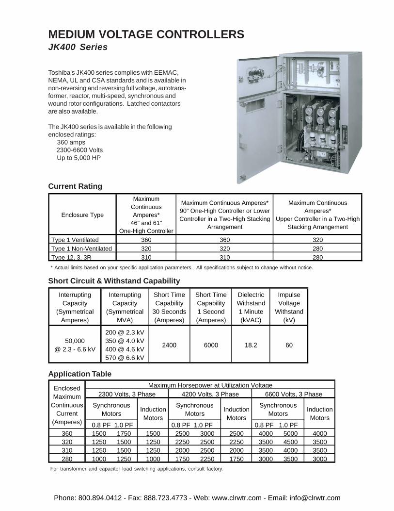
Toshiba's JK400 series complies with EEMAC,NEMA, UL and CSA standards and is available innon-reversing and reversing full voltage, autotrans-former, reactor, multi-speed, synchronous andwound rotor configurations. Latched contactorsare also available.
The JK400 series is available in the followingenclosed ratings: 360 amps 2300-6600 Volts Up to 5,000 HP
Short Circuit & Withstand Capability
Application Table
For transformer and capacitor load switching applications, consult factory.
* Actual limits based on your specific application parameters. All specifications subject to change without notice.
Current Rating
Enclosure Type
Maximum Continuous Amperes*
46" and 61"One-High Controller
Maximum Continuous Amperes*90" One-High Controller or LowerController in a Two-High Stacking
Arrangement
Maximum Continuous Amperes*
Upper Controller in a Two-HighStacking Arrangement
Type 1 Ventilated 360 360 320 Type 1 Non-Ventilated 320 320 280 Type 12, 3, 3R 310 310 280
MEDIUM VOLTAGE CONTROLLERSJK400 Series
InterruptingCapacity
(SymmetricalAmperes)
InterruptingCapacity
(SymmetricalMVA)
Short TimeCapability
30 Seconds(Amperes)
Short TimeCapability1 Second(Amperes)
DielectricWithstand1 Minute(kVAC)
ImpulseVoltage
Withstand(kV)
50,000@ 2.3 - 6.6 kV
200 @ 2.3 kV350 @ 4.0 kV400 @ 4.6 kV570 @ 6.6 kV
2400 6000 18.2 60
2300 Volts, 3 Phase 4200 Volts, 3 Phase 6600 Volts, 3 Phase
0.8 PF 1.0 PF 0.8 PF 1.0 PF 0.8 PF 1.0 PF360 1500 1750 1500 2500 3000 2500 4000 5000 4000320 1250 1500 1250 2250 2500 2250 3500 4500 3500310 1250 1500 1250 2000 2500 2000 3500 4000 3500280 1000 1250 1000 1750 2250 1750 3000 3500 3000
Synchronous Motors Induction
Motors
Enclosed Maximum
Continuous Current
(Amperes)
Maximum Horsepower at Utilization Voltage
Synchronous Motors Induction
Motors
Synchronous Motors Induction
Motors
Phone: 800.894.0412 - Fax: 888.723.4773 - Web: www.clrwtr.com - Email: [email protected]
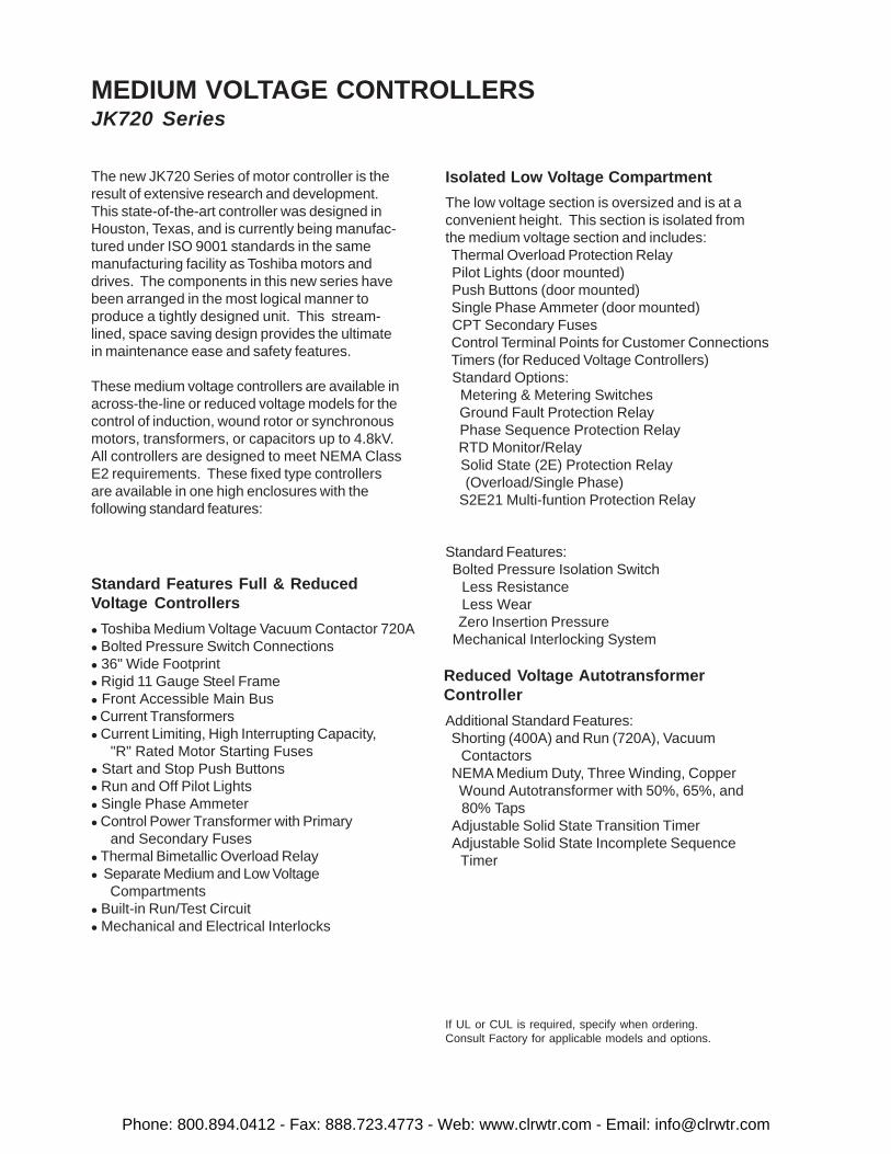
MEDIUM VOLTAGE CONTROLLERSJK720 Series
The new JK720 Series of motor controller is theresult of extensive research and development.This state-of-the-art controller was designed inHouston, Texas, and is currently being manufac-tured under ISO 9001 standards in the samemanufacturing facility as Toshiba motors anddrives. The components in this new series havebeen arranged in the most logical manner toproduce a tightly designed unit. This stream-lined, space saving design provides the ultimatein maintenance ease and safety features.
These medium voltage controllers are available inacross-the-line or reduced voltage models for thecontrol of induction, wound rotor or synchronousmotors, transformers, or capacitors up to 4.8kV.All controllers are designed to meet NEMA ClassE2 requirements. These fixed type controllersare available in one high enclosures with thefollowing standard features:
Standard Features Full & ReducedVoltage Controllers
� Toshiba Medium Voltage Vacuum Contactor 720A� Bolted Pressure Switch Connections� 36" Wide Footprint� Rigid 11 Gauge Steel Frame� Front Accessible Main Bus� Current Transformers� Current Limiting, High Interrupting Capacity, "R" Rated Motor Starting Fuses� Start and Stop Push Buttons� Run and Off Pilot Lights� Single Phase Ammeter� Control Power Transformer with Primary and Secondary Fuses� Thermal Bimetallic Overload Relay� Separate Medium and Low Voltage Compartments� Built-in Run/Test Circuit� Mechanical and Electrical Interlocks
Isolated Low Voltage Compartment
The low voltage section is oversized and is at aconvenient height. This section is isolated fromthe medium voltage section and includes: Thermal Overload Protection Relay Pilot Lights (door mounted) Push Buttons (door mounted) Single Phase Ammeter (door mounted) CPT Secondary Fuses Control Terminal Points for Customer Connections Timers (for Reduced Voltage Controllers) Standard Options: Metering & Metering Switches Ground Fault Protection Relay Phase Sequence Protection Relay RTD Monitor/Relay Solid State (2E) Protection Relay (Overload/Single Phase) S2E21 Multi-funtion Protection Relay
Standard Features: Bolted Pressure Isolation Switch Less Resistance Less Wear Zero Insertion Pressure Mechanical Interlocking System
Reduced Voltage AutotransformerController
Additional Standard Features: Shorting (400A) and Run (720A), Vacuum Contactors NEMA Medium Duty, Three Winding, Copper Wound Autotransformer with 50%, 65%, and 80% Taps Adjustable Solid State Transition Timer Adjustable Solid State Incomplete Sequence Timer
If UL or CUL is required, specify when ordering.Consult Factory for applicable models and options.
Phone: 800.894.0412 - Fax: 888.723.4773 - Web: www.clrwtr.com - Email: [email protected]
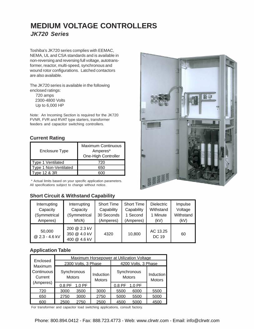
Toshiba's JK720 series complies with EEMAC,NEMA, UL and CSA standards and is available innon-reversing and reversing full voltage, autotrans-former, reactor, multi-speed, synchronous andwound rotor configurations. Latched contactorsare also available.
The JK720 series is available in the followingenclosed ratings: 720 amps 2300-4800 Volts Up to 6,000 HP
Note: An Incoming Section is required for the JK720FVNR, FVR and RVAT type starters, transformerfeeders and capacitor switching controllers.
Current Rating
* Actual limits based on your specific application parameters.All specifications subject to change without notice.
Short Circuit & Withstand Capability
Application Table
For transformer and capacitor load switching applications, consult factory.
MEDIUM VOLTAGE CONTROLLERSJK720 Series
InterruptingCapacity
(SymmetricalAmperes)
InterruptingCapacity
(SymmetricalMVA)
Short TimeCapability
30 Seconds(Amperes)
Short TimeCapability1 Second(Amperes)
DielectricWithstand1 Minute
(kV)
ImpulseVoltage
Withstand(kV)
50,000@ 2.3 - 4.6 kV
200 @ 2.3 kV350 @ 4.0 kV400 @ 4.6 kV
4320 10,800 AC 13.25 DC 19 60
Maximum Horsepower at Utilization Voltage2300 Volts, 3 Phase 4200 Volts, 3 Phase
0.8 PF 1.0 PF 0.8 PF 1.0 PF720 3000 3500 3000 5500 6000 5500650 2750 3000 2750 5000 5500 5000600 2500 2750 2500 4500 5000 4500
Induction Motors
Enclosed Maximum
Continuous Current
(Amperes)
Synchronous Motors Induction
Motors
Synchronous Motors
Enclosure TypeMaximum Continuous
Amperes*One-High Controller
Type 1 Ventilated 720 Type 1 Non-Ventilated 650 Type 12 & 3R 600
Phone: 800.894.0412 - Fax: 888.723.4773 - Web: www.clrwtr.com - Email: [email protected]
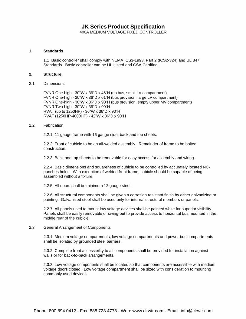
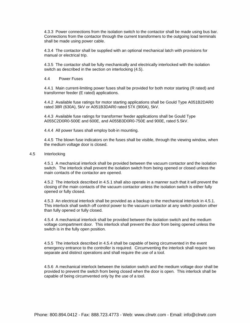
JK Series Product Specification400A MEDIUM VOLTAGE FIXED CONTROLLER
1. Standards
1.1 Basic controller shall comply with NEMA ICS3-1993, Part 2 (ICS2-324) and UL 347Standards. Basic controller can be UL Listed and CSA Certified.
2. Structure
2.1 Dimensions
FVNR One-high - 30"W x 36"D x 46"H (no bus, small LV compartment)FVNR One-high - 30"W x 36"D x 61"H (bus provision, large LV compartment)FVNR One-high - 30"W x 36"D x 90"H (bus provision, empty upper MV compartment)FVNR Two-high - 30"W x 36"D x 90"HRVAT (up to 1250HP) - 36"W x 36"D x 90"HRVAT (1250HP-4000HP) - 42"W x 36"D x 90"H
2.2 Fabrication
2.2.1 11 gauge frame with 16 gauge side, back and top sheets.
2.2.2 Front of cubicle to be an all-welded assembly. Remainder of frame to be boltedconstruction.
2.2.3 Back and top sheets to be removable for easy access for assembly and wiring.
2.2.4 Basic dimensions and squareness of cubicle to be controlled by accurately located NC-punches holes. With exception of welded front frame, cubicle should be capable of beingassembled without a fixture.
2.2.5 All doors shall be minimum 12 gauge steel.
2.2.6 All structural components shall be given a corrosion resistant finish by either galvanizing orpainting. Galvanized steel shall be used only for internal structural members or panels.
2.2.7 All panels used to mount low voltage devices shall be painted white for superior visibility. Panels shall be easily removable or swing-out to provide access to horizontal bus mounted in themiddle rear of the cubicle.
2.3 General Arrangement of Components
2.3.1 Medium voltage compartments, low voltage compartments and power bus compartments shall be isolated by grounded steel barriers.
2.3.2 Complete front accessibility to all components shall be provided for installation againstwalls or for back-to-back arrangements.
2.3.3 Low voltage components shall be located so that components are accessible with mediumvoltage doors closed. Low voltage compartment shall be sized with consideration to mountingcommonly used devices.
Phone: 800.894.0412 - Fax: 888.723.4773 - Web: www.clrwtr.com - Email: [email protected]
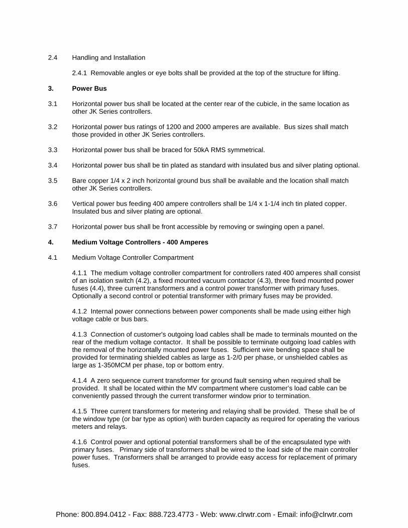
2.4 Handling and Installation
2.4.1 Removable angles or eye bolts shall be provided at the top of the structure for lifting.
3. Power Bus
3.1 Horizontal power bus shall be located at the center rear of the cubicle, in the same location asother JK Series controllers.
3.2 Horizontal power bus ratings of 1200 and 2000 amperes are available. Bus sizes shall matchthose provided in other JK Series controllers.
3.3 Horizontal power bus shall be braced for 50kA RMS symmetrical.
3.4 Horizontal power bus shall be tin plated as standard with insulated bus and silver plating optional.
3.5 Bare copper 1/4 x 2 inch horizontal ground bus shall be available and the location shall matchother JK Series controllers.
3.6 Vertical power bus feeding 400 ampere controllers shall be 1/4 x 1-1/4 inch tin plated copper. Insulated bus and silver plating are optional.
3.7 Horizontal power bus shall be front accessible by removing or swinging open a panel.
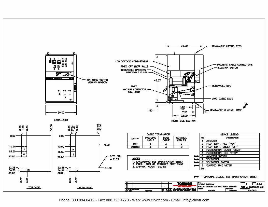
4. Medium Voltage Controllers - 400 Amperes
4.1 Medium Voltage Controller Compartment
4.1.1 The medium voltage controller compartment for controllers rated 400 amperes shall consistof an isolation switch (4.2), a fixed mounted vacuum contactor (4.3), three fixed mounted powerfuses (4.4), three current transformers and a control power transformer with primary fuses. Optionally a second control or potential transformer with primary fuses may be provided.
4.1.2 Internal power connections between power components shall be made using either highvoltage cable or bus bars.
4.1.3 Connection of customer's outgoing load cables shall be made to terminals mounted on therear of the medium voltage contactor. It shall be possible to terminate outgoing load cables withthe removal of the horizontally mounted power fuses. Sufficient wire bending space shall beprovided for terminating shielded cables as large as 1-2/0 per phase, or unshielded cables aslarge as 1-350MCM per phase, top or bottom entry.
4.1.4 A zero sequence current transformer for ground fault sensing when required shall beprovided. It shall be located within the MV compartment where customer’s load cable can beconveniently passed through the current transformer window prior to termination.
4.1.5 Three current transformers for metering and relaying shall be provided. These shall be ofthe window type (or bar type as option) with burden capacity as required for operating the variousmeters and relays.
4.1.6 Control power and optional potential transformers shall be of the encapsulated type with primary fuses. Primary side of transformers shall be wired to the load side of the main controllerpower fuses. Transformers shall be arranged to provide easy access for replacement of primaryfuses.
Phone: 800.894.0412 - Fax: 888.723.4773 - Web: www.clrwtr.com - Email: [email protected]
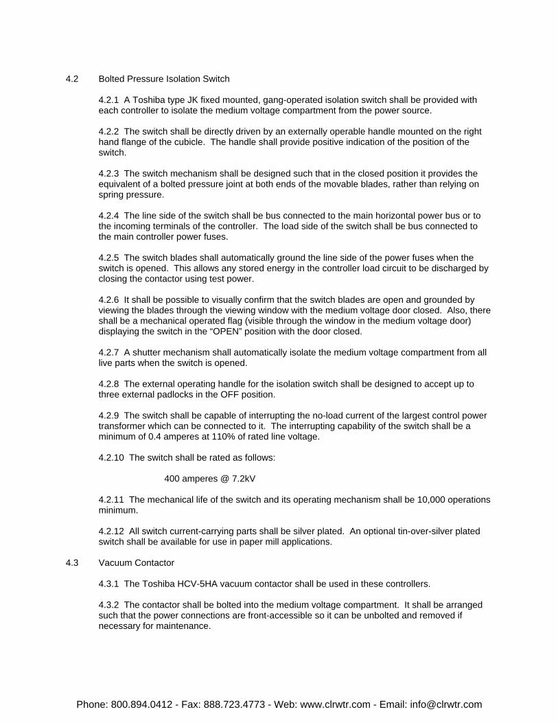
4.2 Bolted Pressure Isolation Switch
4.2.1 A Toshiba type JK fixed mounted, gang-operated isolation switch shall be provided witheach controller to isolate the medium voltage compartment from the power source.
4.2.2 The switch shall be directly driven by an externally operable handle mounted on the righthand flange of the cubicle. The handle shall provide positive indication of the position of theswitch.
4.2.3 The switch mechanism shall be designed such that in the closed position it provides theequivalent of a bolted pressure joint at both ends of the movable blades, rather than relying onspring pressure.
4.2.4 The line side of the switch shall be bus connected to the main horizontal power bus or tothe incoming terminals of the controller. The load side of the switch shall be bus connected tothe main controller power fuses.
4.2.5 The switch blades shall automatically ground the line side of the power fuses when theswitch is opened. This allows any stored energy in the controller load circuit to be discharged byclosing the contactor using test power.
4.2.6 It shall be possible to visually confirm that the switch blades are open and grounded byviewing the blades through the viewing window with the medium voltage door closed. Also, thereshall be a mechanical operated flag (visible through the window in the medium voltage door)displaying the switch in the “OPEN” position with the door closed.
4.2.7 A shutter mechanism shall automatically isolate the medium voltage compartment from alllive parts when the switch is opened.
4.2.8 The external operating handle for the isolation switch shall be designed to accept up tothree external padlocks in the OFF position.
4.2.9 The switch shall be capable of interrupting the no-load current of the largest control powertransformer which can be connected to it. The interrupting capability of the switch shall be aminimum of 0.4 amperes at 110% of rated line voltage.
4.2.10 The switch shall be rated as follows:
400 amperes @ 7.2kV
4.2.11 The mechanical life of the switch and its operating mechanism shall be 10,000 operationsminimum.
4.2.12 All switch current-carrying parts shall be silver plated. An optional tin-over-silver platedswitch shall be available for use in paper mill applications.
4.3 Vacuum Contactor
4.3.1 The Toshiba HCV-5HA vacuum contactor shall be used in these controllers.
4.3.2 The contactor shall be bolted into the medium voltage compartment. It shall be arrangedsuch that the power connections are front-accessible so it can be unbolted and removed ifnecessary for maintenance.
Phone: 800.894.0412 - Fax: 888.723.4773 - Web: www.clrwtr.com - Email: [email protected]
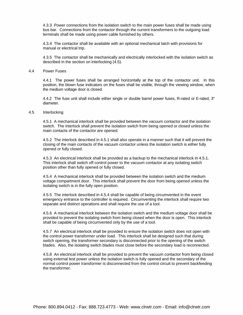
4.3.3 Power connections from the isolation switch to the main power fuses shall be made usingbus bar. Connections from the contactor through the current transformers to the outgoing loadterminals shall be made using power cable furnished by others.
4.3.4 The contactor shall be available with an optional mechanical latch with provisions formanual or electrical trip.
4.3.5 The contactor shall be mechanically and electrically interlocked with the isolation switch asdescribed in the section on interlocking (4.5).
4.4 Power Fuses
4.4.1 The power fuses shall be arranged horizontally at the top of the contactor unit. In thisposition, the blown fuse indicators on the fuses shall be visible, through the viewing window, whenthe medium voltage door is closed.
4.4.2 The fuse unit shall include either single or double barrel power fuses, R-rated or E-rated, 3"diameter.
4.5 Interlocking
4.5.1 A mechanical interlock shall be provided between the vacuum contactor and the isolationswitch. The interlock shall prevent the isolation switch from being opened or closed unless themain contacts of the contactor are opened.
4.5.2 The interlock described in 4.5.1 shall also operate in a manner such that it will prevent theclosing of the main contacts of the vacuum contactor unless the isolation switch is either fullyopened or fully closed.
4.5.3 An electrical interlock shall be provided as a backup to the mechanical interlock in 4.5.1. This interlock shall switch off control power to the vacuum contactor at any isolating switchposition other than fully opened or fully closed.
4.5.4 A mechanical interlock shall be provided between the isolation switch and the mediumvoltage compartment door. This interlock shall prevent the door from being opened unless theisolating switch is in the fully open position.
4.5.5 The interlock described in 4.5.4 shall be capable of being circumvented in the eventemergency entrance to the controller is required. Circumventing the interlock shall require twoseparate and distinct operations and shall require the use of a tool.
4.5.6 A mechanical interlock between the isolation switch and the medium voltage door shall beprovided to prevent the isolating switch from being closed when the door is open. This interlockshall be capable of being circumvented only by the use of a tool.
4.5.7 An electrical interlock shall be provided to ensure the isolation switch does not open withthe control power transformer under load. This interlock shall be designed such that duringswitch opening, the transformer secondary is disconnected prior to the opening of the switchblades. Also, the isolating switch blades must close before the secondary load is reconnected.
4.5.8 An electrical interlock shall be provided to prevent the vacuum contactor from being closedusing external test power unless the isolation switch is fully opened and the secondary of thenormal control power transformer is disconnected from the control circuit to prevent backfeedingthe transformer.
Phone: 800.894.0412 - Fax: 888.723.4773 - Web: www.clrwtr.com - Email: [email protected]
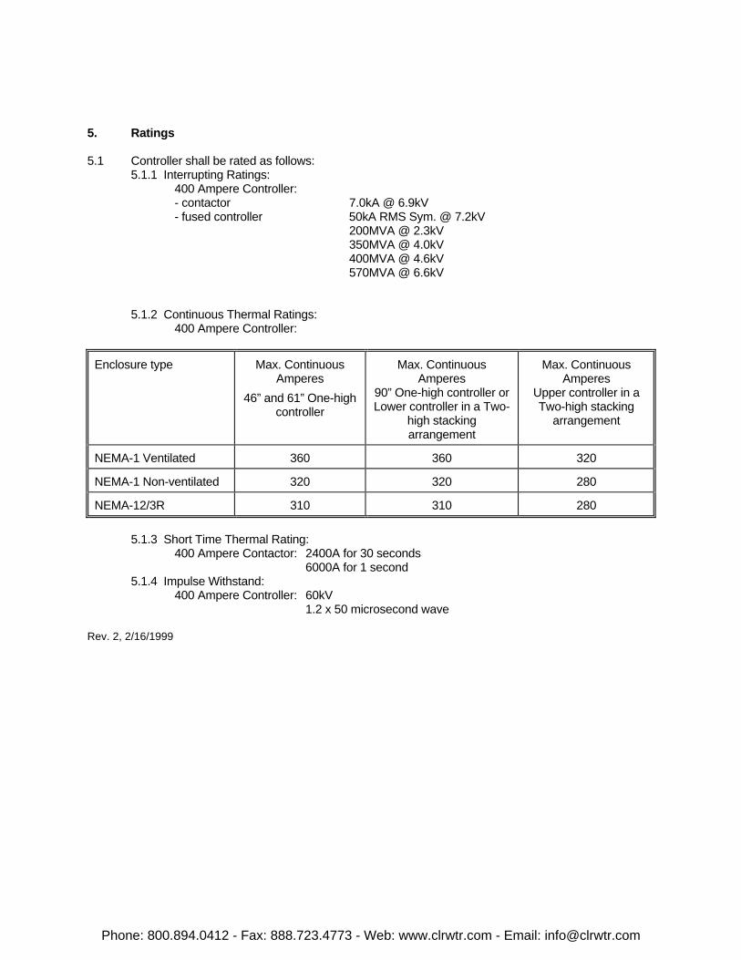
5. Ratings
5.1 Controller shall be rated as follows:5.1.1 Interrupting Ratings:
400 Ampere Controller:- contactor 7.0kA @ 6.9kV- fused controller 50kA RMS Sym. @ 7.2kV
200MVA @ 2.3kV350MVA @ 4.0kV400MVA @ 4.6kV570MVA @ 6.6kV
5.1.2 Continuous Thermal Ratings:400 Ampere Controller:
Enclosure type Max. ContinuousAmperes
46” and 61” One-highcontroller
Max. ContinuousAmperes
90” One-high controller orLower controller in a Two-
high stackingarrangement
Max. ContinuousAmperes
Upper controller in aTwo-high stacking
arrangement
NEMA-1 Ventilated 360 360 320
NEMA-1 Non-ventilated 320 320 280
NEMA-12/3R 310 310 280
5.1.3 Short Time Thermal Rating:400 Ampere Contactor: 2400A for 30 seconds
6000A for 1 second5.1.4 Impulse Withstand:
400 Ampere Controller: 60kV1.2 x 50 microsecond wave
Rev. 2, 2/16/1999
Phone: 800.894.0412 - Fax: 888.723.4773 - Web: www.clrwtr.com - Email: [email protected]
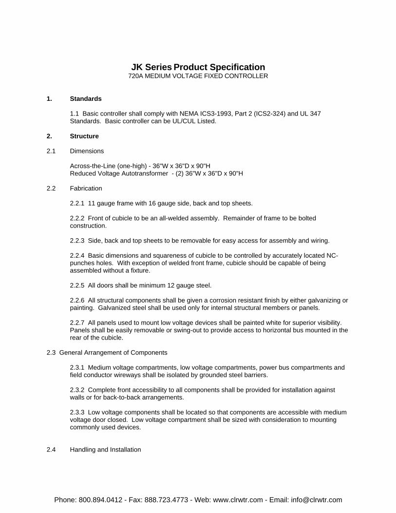
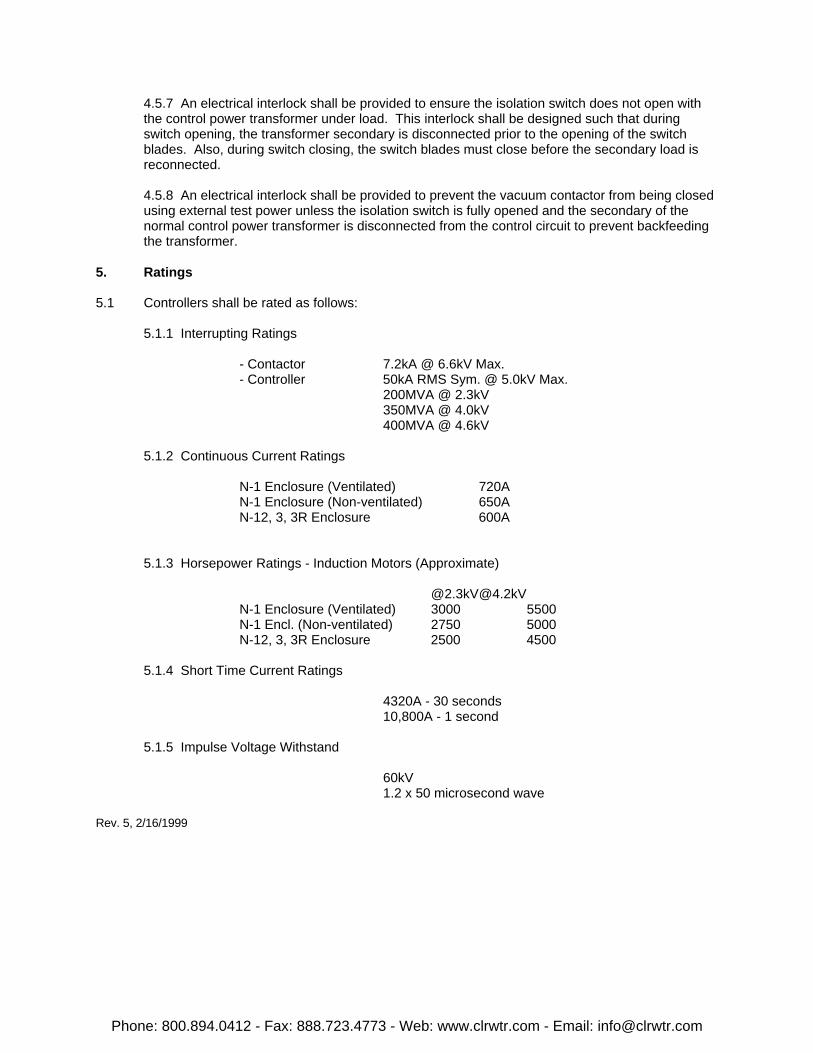
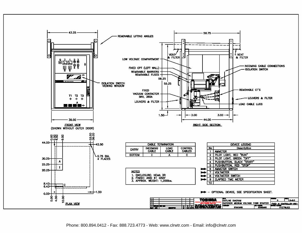
JK Series Product Specification720A MEDIUM VOLTAGE FIXED CONTROLLER
1. Standards
1.1 Basic controller shall comply with NEMA ICS3-1993, Part 2 (ICS2-324) and UL 347Standards. Basic controller can be UL/CUL Listed.
2. Structure
2.1 Dimensions
Across-the-Line (one-high) - 36"W x 36"D x 90"HReduced Voltage Autotransformer - (2) 36"W x 36"D x 90"H
2.2 Fabrication
2.2.1 11 gauge frame with 16 gauge side, back and top sheets.
2.2.2 Front of cubicle to be an all-welded assembly. Remainder of frame to be boltedconstruction.
2.2.3 Side, back and top sheets to be removable for easy access for assembly and wiring.
2.2.4 Basic dimensions and squareness of cubicle to be controlled by accurately located NC-punches holes. With exception of welded front frame, cubicle should be capable of beingassembled without a fixture.
2.2.5 All doors shall be minimum 12 gauge steel.
2.2.6 All structural components shall be given a corrosion resistant finish by either galvanizing orpainting. Galvanized steel shall be used only for internal structural members or panels.
2.2.7 All panels used to mount low voltage devices shall be painted white for superior visibility. Panels shall be easily removable or swing-out to provide access to horizontal bus mounted in therear of the cubicle.
2.3 General Arrangement of Components
2.3.1 Medium voltage compartments, low voltage compartments, power bus compartments andfield conductor wireways shall be isolated by grounded steel barriers.
2.3.2 Complete front accessibility to all components shall be provided for installation againstwalls or for back-to-back arrangements.
2.3.3 Low voltage components shall be located so that components are accessible with mediumvoltage door closed. Low voltage compartment shall be sized with consideration to mountingcommonly used devices.
2.4 Handling and Installation
Phone: 800.894.0412 - Fax: 888.723.4773 - Web: www.clrwtr.com - Email: [email protected]
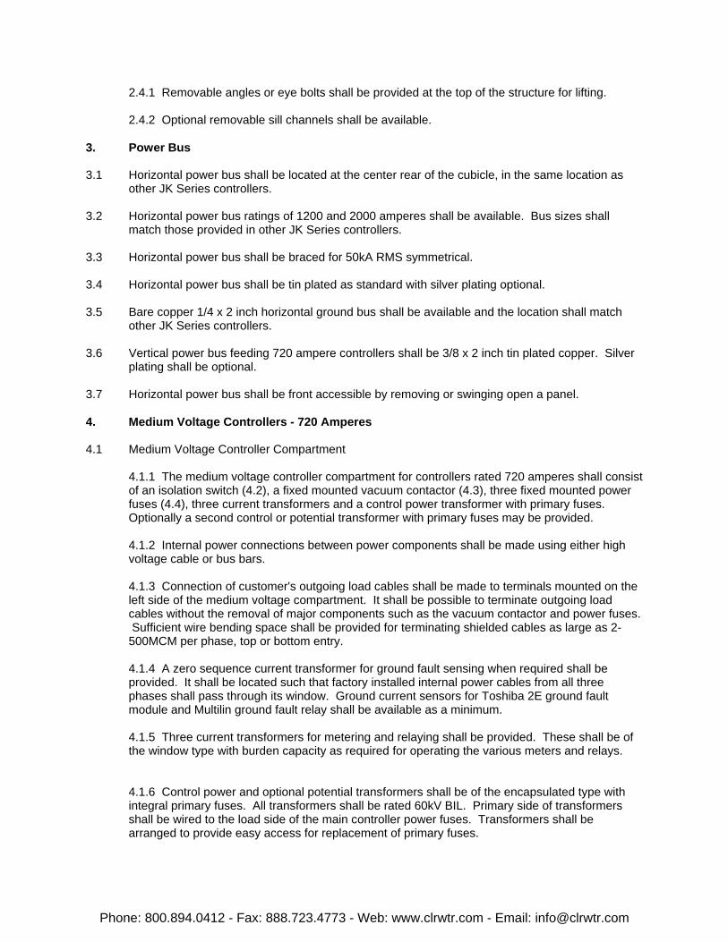
2.4.1 Removable angles or eye bolts shall be provided at the top of the structure for lifting.
2.4.2 Optional removable sill channels shall be available.
3. Power Bus
3.1 Horizontal power bus shall be located at the center rear of the cubicle, in the same location asother JK Series controllers.
3.2 Horizontal power bus ratings of 1200 and 2000 amperes shall be available. Bus sizes shallmatch those provided in other JK Series controllers.
3.3 Horizontal power bus shall be braced for 50kA RMS symmetrical.
3.4 Horizontal power bus shall be tin plated as standard with silver plating optional.
3.5 Bare copper 1/4 x 2 inch horizontal ground bus shall be available and the location shall matchother JK Series controllers.
3.6 Vertical power bus feeding 720 ampere controllers shall be 3/8 x 2 inch tin plated copper. Silverplating shall be optional.
3.7 Horizontal power bus shall be front accessible by removing or swinging open a panel.
4. Medium Voltage Controllers - 720 Amperes
4.1 Medium Voltage Controller Compartment
4.1.1 The medium voltage controller compartment for controllers rated 720 amperes shall consistof an isolation switch (4.2), a fixed mounted vacuum contactor (4.3), three fixed mounted powerfuses (4.4), three current transformers and a control power transformer with primary fuses. Optionally a second control or potential transformer with primary fuses may be provided.
4.1.2 Internal power connections between power components shall be made using either highvoltage cable or bus bars.
4.1.3 Connection of customer's outgoing load cables shall be made to terminals mounted on theleft side of the medium voltage compartment. It shall be possible to terminate outgoing loadcables without the removal of major components such as the vacuum contactor and power fuses. Sufficient wire bending space shall be provided for terminating shielded cables as large as 2-500MCM per phase, top or bottom entry.
4.1.4 A zero sequence current transformer for ground fault sensing when required shall beprovided. It shall be located such that factory installed internal power cables from all threephases shall pass through its window. Ground current sensors for Toshiba 2E ground faultmodule and Multilin ground fault relay shall be available as a minimum.
4.1.5 Three current transformers for metering and relaying shall be provided. These shall be ofthe window type with burden capacity as required for operating the various meters and relays.
4.1.6 Control power and optional potential transformers shall be of the encapsulated type withintegral primary fuses. All transformers shall be rated 60kV BIL. Primary side of transformersshall be wired to the load side of the main controller power fuses. Transformers shall bearranged to provide easy access for replacement of primary fuses.
Phone: 800.894.0412 - Fax: 888.723.4773 - Web: www.clrwtr.com - Email: [email protected]
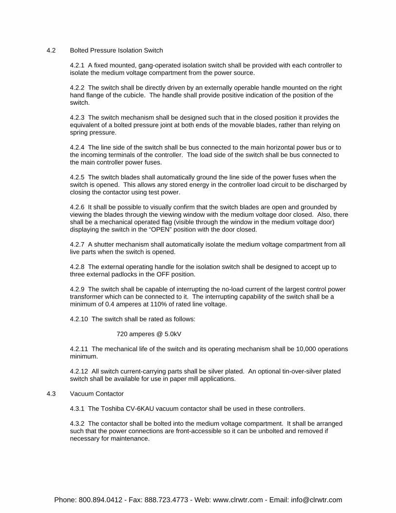
4.2 Bolted Pressure Isolation Switch
4.2.1 A fixed mounted, gang-operated isolation switch shall be provided with each controller toisolate the medium voltage compartment from the power source.
4.2.2 The switch shall be directly driven by an externally operable handle mounted on the righthand flange of the cubicle. The handle shall provide positive indication of the position of theswitch.
4.2.3 The switch mechanism shall be designed such that in the closed position it provides theequivalent of a bolted pressure joint at both ends of the movable blades, rather than relying onspring pressure.
4.2.4 The line side of the switch shall be bus connected to the main horizontal power bus or tothe incoming terminals of the controller. The load side of the switch shall be bus connected tothe main controller power fuses.
4.2.5 The switch blades shall automatically ground the line side of the power fuses when theswitch is opened. This allows any stored energy in the controller load circuit to be discharged byclosing the contactor using test power.
4.2.6 It shall be possible to visually confirm that the switch blades are open and grounded byviewing the blades through the viewing window with the medium voltage door closed. Also, thereshall be a mechanical operated flag (visible through the window in the medium voltage door)displaying the switch in the “OPEN” position with the door closed.
4.2.7 A shutter mechanism shall automatically isolate the medium voltage compartment from alllive parts when the switch is opened.
4.2.8 The external operating handle for the isolation switch shall be designed to accept up tothree external padlocks in the OFF position.
4.2.9 The switch shall be capable of interrupting the no-load current of the largest control powertransformer which can be connected to it. The interrupting capability of the switch shall be aminimum of 0.4 amperes at 110% of rated line voltage.
4.2.10 The switch shall be rated as follows:
720 amperes @ 5.0kV
4.2.11 The mechanical life of the switch and its operating mechanism shall be 10,000 operationsminimum.
4.2.12 All switch current-carrying parts shall be silver plated. An optional tin-over-silver platedswitch shall be available for use in paper mill applications.
4.3 Vacuum Contactor
4.3.1 The Toshiba CV-6KAU vacuum contactor shall be used in these controllers.
4.3.2 The contactor shall be bolted into the medium voltage compartment. It shall be arrangedsuch that the power connections are front-accessible so it can be unbolted and removed ifnecessary for maintenance.
Phone: 800.894.0412 - Fax: 888.723.4773 - Web: www.clrwtr.com - Email: [email protected]
4.3.3 Power connections from the isolation switch to the contactor shall be made using bus bar. Connections from the contactor through the current transformers to the outgoing load terminalsshall be made using power cable.
4.3.4 The contactor shall be supplied with an optional mechanical latch with provisions formanual or electrical trip.
4.3.5 The contactor shall be fully mechanically and electrically interlocked with the isolationswitch as described in the section on interlocking (4.5).
4.4 Power Fuses
4.4.1 Main current-limiting power fuses shall be provided for both motor starting (R rated) andtransformer feeder (E rated) applications.
4.4.2 Available fuse ratings for motor starting applications shall be Gould Type A051B2DAR0rated 38R (630A), 5kV or A051B3DAR0 rated 57X (900A), 5kV.
4.4.3 Available fuse ratings for transformer feeder applications shall be Gould TypeA055C2D0R0-500E and 600E, and A055B3D0R0-750E and 900E, rated 5.5kV.
4.4.4 All power fuses shall employ bolt-in mounting.
4.4.5 The blown fuse indicators on the fuses shall be visible, through the viewing window, whenthe medium voltage door is closed.
4.5 Interlocking
4.5.1 A mechanical interlock shall be provided between the vacuum contactor and the isolationswitch. The interlock shall prevent the isolation switch from being opened or closed unless themain contacts of the contactor are opened.
4.5.2 The interlock described in 4.5.1 shall also operate in a manner such that it will prevent theclosing of the main contacts of the vacuum contactor unless the isolation switch is either fullyopened or fully closed.
4.5.3 An electrical interlock shall be provided as a backup to the mechanical interlock in 4.5.1. This interlock shall switch off control power to the vacuum contactor at any switch position otherthan fully opened or fully closed.
4.5.4 A mechanical interlock shall be provided between the isolation switch and the mediumvoltage compartment door. This interlock shall prevent the door from being opened unless theswitch is in the fully open position.
4.5.5 The interlock described in 4.5.4 shall be capable of being circumvented in the eventemergency entrance to the controller is required. Circumventing the interlock shall require twoseparate and distinct operations and shall require the use of a tool.
4.5.6 A mechanical interlock between the isolation switch and the medium voltage door shall beprovided to prevent the switch from being closed when the door is open. This interlock shall becapable of being circumvented only by the use of a tool.
Phone: 800.894.0412 - Fax: 888.723.4773 - Web: www.clrwtr.com - Email: [email protected]
4.5.7 An electrical interlock shall be provided to ensure the isolation switch does not open withthe control power transformer under load. This interlock shall be designed such that duringswitch opening, the transformer secondary is disconnected prior to the opening of the switchblades. Also, during switch closing, the switch blades must close before the secondary load isreconnected.
4.5.8 An electrical interlock shall be provided to prevent the vacuum contactor from being closedusing external test power unless the isolation switch is fully opened and the secondary of thenormal control power transformer is disconnected from the control circuit to prevent backfeedingthe transformer.
5. Ratings
5.1 Controllers shall be rated as follows:
5.1.1 Interrupting Ratings
- Contactor 7.2kA @ 6.6kV Max.- Controller 50kA RMS Sym. @ 5.0kV Max.
200MVA @ 2.3kV350MVA @ 4.0kV400MVA @ 4.6kV
5.1.2 Continuous Current Ratings
N-1 Enclosure (Ventilated) 720AN-1 Enclosure (Non-ventilated) 650AN-12, 3, 3R Enclosure 600A
5.1.3 Horsepower Ratings - Induction Motors (Approximate)
@[email protected] Enclosure (Ventilated) 3000 5500 N-1 Encl. (Non-ventilated) 2750 5000 N-12, 3, 3R Enclosure 2500 4500
5.1.4 Short Time Current Ratings
4320A - 30 seconds10,800A - 1 second
5.1.5 Impulse Voltage Withstand
60kV 1.2 x 50 microsecond wave
Rev. 5, 2/16/1999
Phone: 800.894.0412 - Fax: 888.723.4773 - Web: www.clrwtr.com - Email: [email protected]
g~ ~ c:i...: cO
I ,J I 0.00
10.50
15.50
20.50
32.38 34.3a~=Jc 36.00
" ~ aq 0 .0
TOP VIEW
eiQg~e lil~~~
~
V' .... ~-ISOLATION SWITCH VIEWING WINDOW
T1 T2
+ + A -
~30.00~ 0 0
:iii
FRONT VIEW
8 t'olmm Oii')..,
c:ic:i..: .0
~g gj~
0.00 --Ht----1------+1
10.50E 15.50
I 20.50
32.38 34.JS~C I 36.00 I
~ c:i
" aq co
PLAN VIEW
9.00
36.00 ~ REMOVABLE LIFTING EYES
""T"'""--!:-- I I • •
LOW VOLTAGE COMPARTMENT
FIXED CPT (LEFT WALL) REMOVABLE BARRIERS
REMOVABLE FUSES
INCOMING CABLE CONNECTIONS ISOLATION SWITCH
0.75 DIA. 4 PLCS.
FIXED VACUUM CONTACTOR
5KV, 360A
llf" · UWl CABLE LUGS
1.50 J ~.
3.oo-J ,f L ~50 REMOVABLE CHANNEL BASE
22.00
RIGHI SIPE SECTION
CABLE TERMINATION DEVICE LEGEND
ENTRY INCOMING LOAD CONTROL CABLE CABLE CABLES
No DeacriDtion 1 AMMETER
TOP I A c 2 PILOT LIGHT, RED "RUN" BOTTOM I A c 3 PILOT LIGHT. GREEN "OFF"
4 PUSHBUTTON, BLACK -sTART" 5 PUSHBUTTON, RED -sTOP" 6 AMMETER SWITCH
~ 7 VOLTMETER 1 • ENCLOSURE: SEE SPECIFICATION SHEET
.. .. .. .. 8 VOLTMETER SWITCH 9 ELAPSED TIME METER 10
2. FINISH: ANSI 61 TEXTURED GRAY PAINT 3. APPROX. WEIGHT: 9001be.
.. - OPTIONAL DEVICE, SEE SPECIFICATION SHEET.
....... IOUTUI£ DIAGRAM FW I I I , -~-.......- INDOOR MEDILll YOLTACE NjR STARTER &aa-WWW mw --... -
Phone: 800.894.0412 - Fax: 888.723.4773 - Web: www.clrwtr.com - Email: [email protected]
1 · 43.25 • 1 /"""""'LE umNG '""'-"' ~ ~
0 n r- 0
I I
10 ~
~~iQee lil~~~
0
~-__,.e__---.... r--.,.._
Ill
T1T2TJI + + +
A ····-
IO ~
,....
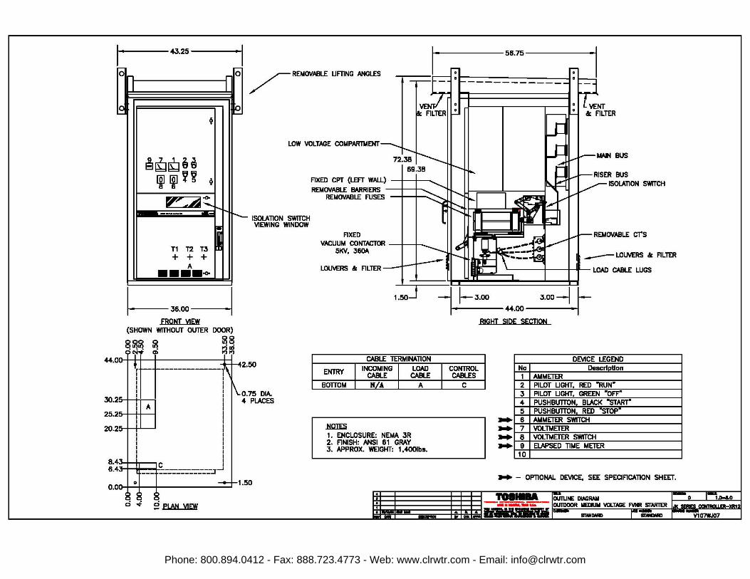
LOW VOLTAGE COMPARTMENT
ISOLATION SWITCH VIEWING WINDOW
FIXED CPT (LEFT WALL) a;; REMOVABLE ~RIERS
REMOVABLE FUSES . 58.25
FIXED VACUUM CONIACTOR +-+--.
51<V, J60A
LOUVERS ai FILTER ~
o---------56.75------.....
INCOMING CABLE CONNECTIONS ISOLATION SWITCH
Ill'" . ' I I I ' L~ CABLE LUGS
~J6.00___j -L~J.00 1.50
44.00 J.00~ r-
FRONT VIEW (SHOWN WITHOUT OUTER DOOR)
8SS S oc-i• oi
~a ~:fl
:::5 I lf:o_-£-----------------------.r~ a~ a
- PLAN VIEW
0.75 DIA. 4 PLACES
1.50
CABLE TERMINATION
ENlRY I IN~~G I LOAD CABLE
BOTTOM I ] I A
~ 1. ENCLOSURE: NEMA JR 2. FINISH: ANSI 61 GRAY J. APPROX. WEIGHT: 1,2001bs.
t 1iMili&h•--·-· _...
I
I CONTROL CABLES
I c
.. •
I RIGHT SIDE SECTION
.. .. .. ..
No 1 2 J 4 5 6 7 8 9
10
DEVICE LEGEND DescriDtion
AMMETER PILOT LIGHT, RED •RuN• PILOT LIGHT, GREEN •oFF" PUSHBUTTON, BLACK -sTART" PUSHBUTTON, RED -sTOP" AMMETER SWITCH VOLTMETER VOLTMETER SWITCH ELAPSED TIME METER
_,. - OPTIONAL DEVICE, SEE SPECIFICATION SHEET.
llTAlllWE
Phone: 800.894.0412 - Fax: 888.723.4773 - Web: www.clrwtr.com - Email: [email protected]
~
~iQg6a ljlljl~~ ~
~ ... A:!:. ""' -
T1T2T3j + + +
A -l-30.00-l
FRONT VIEW
0111 ID 01"1.., c:i..: cO
0 0
~ o.oo-1+--+--------1
10.50
15.50
20.50
32.38 34.38 ='1f-3 c I 36.00 I
..... aq 0
fii .0
roe VIEW
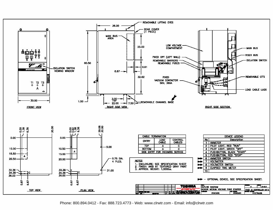
ISOLATION SWITCH VIEWING WINDOW
60.50
r---, MAIN BUS ----...........1
AREA 1'._ I I
I ii 25.oo I .
I I I I I L.---·
j -ll---10.91
6.67
32.62
LOW VOLTAGE COMPARTMENT
FIXED CPT (LEFT WAU.) REMOVABLE BAARIERS
REMOVABLE FUSES
MAIN BUS
ISOLATION SWITCH
REMOVABLE CT'S FIXED VACUUM CONTACTOR
5KV, 360A.
::!==:::=" J 1.00J 1 ~----1_1~:6--. I'
I< , LOAD CABLE LUGS .
8Sl~ '! c:ic:i..: .0
~8 gj~
0.00 --Ht----1------+1
10.50~
15.50~ 20.50 I' I
32.38 34.JS~C I 36.00 I
fii c:i
..... aq co
PLAN VIEW
I- 22.00 7.50 EMOVABLE CHANNEL BASE
RIGHT SIDE VIEW
9.00
0.75 DIA. 4 PLCS.
CABLE TERMINATION
ENTRY LOAD CONTROL CABLE CABLES
TOP A c BOTTOM A c
SIDE EN'TRY FOR INCOMING SERVICE
~ 1 • ENCLOSURE: SEE SPECIFICATION SHEET 2. FINISH: ANSI 61 TEXTURED GRAY PAINT 3. APPROX. WEIGHT: 1,000lba.
.. .. .. ..
RIGHI SIDE SECTION
DEVICE LEGEND No DeacriDtion 1 AMMETER 2 PILOT LIGHT, RED "RUN• 3 PILOT LIGHT, GREEN •oFF" 4 PUSHBUTTON, BLACK "STARr 5 PUSHBUTTON, RED "STOP" 6 AMMETER SWITCH 7 VOLTMETER 8 VOLTMETER SWITCH 9 ELAPSED TIME METER 10
.. - OPTIONAL DEVICE, SEE SPECIFICATION SHEET •
......... OUTUNE DIAGRAM p 1--1-- I• I a 1.1 -~~-.......- INDOOR MEDILll YOLTACE FVNR STARTER
• - _... • .. .,. - STMDMD
Phone: 800.894.0412 - Fax: 888.723.4773 - Web: www.clrwtr.com - Email: [email protected]
1
. 43.25 • I -------56.75--------
-0
IO ~
-n r- 0
I I
IO ~
~
9~~aa rai~~~ ~
V'~"°" --- .__ 1"--i-.
"'" •
T1T2T31 + + +
A ····-~36.00~
FRONT VIEW (SHOWN WITHOUT OUTER DOOR)
8~~ ~ ~~ "t'i..t Qi ~~
/REMOVABLE LIFTING ANGLES
LOW VOLTAGE COMPARTMENT
ISOLATION SWITCH VIEWING WINDOW
2.50
0.75 DIA. <!- PLACES
FIXED CPT (LEFT WALL) I I ..._ REMOVABLE BARRIERS
REMOVABLE FUSES
FIXED VACUUM CONTACTOR I I ..__
5KV, 360A
LOUVERS & FILTER
CABLE TERMINATION
ENlRY
BOTTOM
~
INCOMING CABLE N/A
LOAD CABLE
A
1. ENCLOSURE: NEMA JR 2. FINISH: ANSI 61 GRAY 3. APPROX. WEIGHT: 1,<l-OOlbs.
1.50
0 0 0 c:i ..t- g PLAN VIEW t
• liiiiiih• --·-· _...
-----------
llP' • ' , I I If LOAD CABLE WGS
-1 ~3.00 1- #.00
3.00~ r-~I
RIGHT SIDE SECTION
CONTROL CABLES
c
.. •
.. .. .. ..
No 1 2 3
• 5 6 7 8 9
10
DEVICE LEGEND DescriDtion
AMMETER PILOT LIGHT, RED •RuN• PILOT LIGHT, GREEN •oFF" PUSHBUTTON, BLACK -sTART• PUSHBUTTON, RED -slop• AMMETER SWITCH VOLTMETER VOLTMETER SWITCH ELAPSED TIME METER
_,. - OPTIONAL DEVICE, SEE SPECIFICATION SHEET.
llTAlllWE
Phone: 800.894.0412 - Fax: 888.723.4773 - Web: www.clrwtr.com - Email: [email protected]
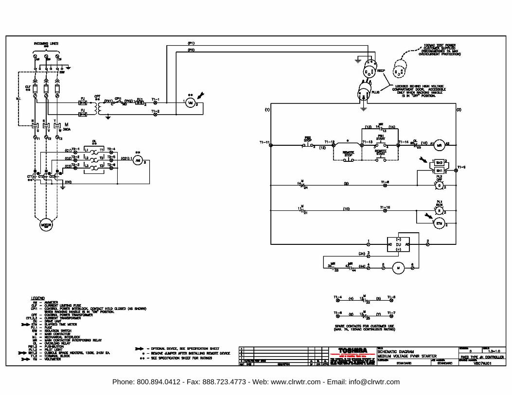
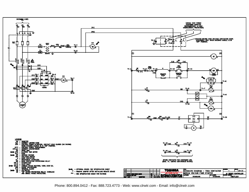
INCCMfi LtES
.----~
:-f ~ I f ~-t~-1:. ~ I ClF
I ** I I
llJ. I
I I I RI SI T L ___ {.l.J G.l.J G.l.J M
~I:~~ I I I I I I I I I I I I r--r I I I I .. I I I I I I I I
I I I I I I I I )
~'9'
.1ESlEllD Ml - MllEIER
ClF - CUIREllT UmwG FUSE
•• TI:-1
TI-2
Cl'U - ~iw:"~~~ Cl.ll!IED ~ 9ltClllO
CPI" - CONINJI. POWEii -cn't"l:~-
.,. Elli - ElllPIED lllE llEIEll FU,1 - FUSE ISW -
II -llJ. -llR -Cl. -
PB1,2 - P\B9Jmlll Pl.1,2 - PIDT LIGHT
... IH1.2 - Cl8IU FllCE ~ 1-, 24111 rA. TI.2 - t-. aoa<
... VII - lllllJllEIDI
... -----~9EI' • - - ~ llf10 1-.uND REllOl'E DlWE •• - SEE SPB:IFICATION SHm FOR MllNCS ...
(1)
,I
8:\. ,.,~ ..... ,
I 1...-...._1 Rm' r .(
~-"
_, __ ..
>.,a,..,
LCICA1ED - - \'Oll'/GE CCllPIM1llEN1" DDQR. ACCESSllLE PWG Cll..Y MEI ~ IWIDLE
IS II "CIF1"' l'OllllllN.
(2)
P81
T1-11. ,..lf-0 TI-,., • ~~ Jon-14 ~ (.S) -·I ' 2 (12) 01 H
14~ S4
11~ 21
-- -
I ~i 'IW I L..--a...i.D--+----o~---J
TI-I
10: T1~10
TI-4 (4) 1~11 00 TI-5 8 122 8
Tl-I 00 1eill m TI-7 e r2ii e 1PME COllll\CIS R>ll CUSllllllER USE (!Ml. 7A, 1DW: CIDlflNJllU!I IWlllDJ
,. ....
2
--............------ 1•~1UM llUL.11111.MC. r ........ ~•""'•en ~JI< CQNI1111Q I IW tMW ~ ........ ~
irfiiiiTj;jiJ u.........num STAii~
Phone: 800.894.0412 - Fax: 888.723.4773 - Web: www.clrwtr.com - Email: [email protected]
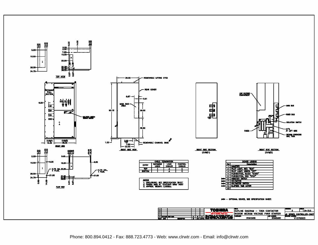
~~
+ A
_j~11 C:-1 BlllLm
~~
!:!:!!...!!!!
90.11
38.CID-f.-~ LE1NI E.YEB
&171 ~-~·
i L
--211.00
32.112
~H .J ,~_r-'L!:~~~NEL_;
llA!IT •YD
tL.I*.·
ClllLE 'l!NllWICN
- 1-:::-1.: I~ la' I I I A I c
BOmllil I A c
JlllDEI 1. EHCl.OL!URE: SEE SPB:IFIClllCll SHEEr :Z. ,_ - It 'IDllURED _, FWNT :s.-.-=.a.-
llA!IT•BIQ! (CUBf1)
llA!IT IQE !l!fC!Q! (CUllf2)
- - - -. - -- 11£E!'.
,. ....
..
lllwl-- - l:l:.l;.l11iiiiiim1=" MWOL.W VULI....._ rvn..z:.:=·- Ml&.~ STAii~
Phone: 800.894.0412 - Fax: 888.723.4773 - Web: www.clrwtr.com - Email: [email protected]
1NCOM1i UNES
,---A--..
r-----1 I I I
I cu I I
llJ. I
I I I RJ, 9:.L T:l.: .II...
~~7a [I~ [t~
I I I I J l,9,
1'llElQ All - AlllE'IER CU - QllAENT UlllllllCI FUIE
•• TI-1
TI,-2
7
~
CPl1 - Clll1llCll. PIMR ll1IRLOa(. CONTloCT HELD CU&D (AS 9Hc.I) lllEN RAaCINGI IWILE II IN 'al" POaTIOll.
CP11 - Clll1llCll. POllEll --en,~ =~~ER .. Elli - EUPIEll - IE1Ell F\1.1 - FUSE .. Gii - GllllJllD
ISW - ISCLA11Cll II - llAIN COii'
llJ. - lllEOWllCM. IMTEll.DCK llR - llAIN COllTACllR IM1IRPO!lllCI llDAY
PBl,2 - PllllBJTlllN Pl.1,2 - PlDT UGllT
.. ~ : ~~'llRS, .-. 240Y E:A.
.. TI~ =~a.oac 2E - •r llDRlR PllOIEC1IClll RDA~ ~
AND SlllCl£ l'ttASE PllOIEC11Clll.
.. - CP110NAI. DE\4CE, 9EE 9PECIF1CATION SHEET * - REMCM: olUll'ER N'10 IMSTALUMO llDIOIE DE'<ICE
** - 9EE 1PEIJF1CA11Cll lltEET FOR RA~
TI-4
14~ '24
11~ '21
TI-s
------1 _...
IZIVAC TE!ll'PIMR CISRMR lll'l'l.lm
!RECCMIENDED 7A llAX OWllCURREHT PAO'IECllON)
~
T2-lrR~~ aJ_j FWD~ 1~1:.llT::lL~':t~.lLCOll~'fST I "llFF'" POSllON.
. L __ _
• sr"mr ~_J_
_J
I ~I 'Mr L_ - I - I _J_ i ~~----o o----J
TI-14
TI-fl
,.,
TI-11 011 ,It.. cm TI-11 e IJi e
TI-11 Oil ,, 0., TI-11 e fa e
·- CONTM:Tll FOR aJl11Mll UE (lllAX. 7A. 120YAC CONllllUCUS RATIR)
,. ....
~TI-fl
TI-fl
A2 M:I I 0 "'TI-15
~ --..ii'liiiiiiiii-........- FM 11U..1Aa. ~- 51AKlt.K- r-t• qll!1l!qill! I ~~ STANDARD r
Phone: 800.894.0412 - Fax: 888.723.4773 - Web: www.clrwtr.com - Email: [email protected]
Medium Voltage Motor
G7 Drive
ADJUSTABLE SPEED DRIVES MOTORS CONTROLS UPS INSTRUMENTATION PLC
Available Through:
TOSHIBA - Quality by DesignOur company culture and history is strongly rooted in quality. Our designs are technologically innovative and our products are manufactured from start to end using only the highest quality foreign and domestic parts.
Product WarrantyToshiba offers a comprehensive warranty program on its full line of industrialproducts. Consult your salesperson or the factory for specific information.
Need to Know More?Be sure to visit our website for the latest information on Toshiba products.
Customer Support ServicesToshiba offers 24 hour service nationwide. For assistance of any type, call: 1-800-231-1412
North America Headquarters & Manufacturing Facilities (Houston, TX)
Phone: 800.894.0412 - Fax: 888.723.4773 - Web: www.clrwtr.com - Email: [email protected]