TOSHIBA 3PHASE INDUCTION MOTOR - prodrives.co.th Motor/1... · CKMS-0701 TOSHIBA 3PHASE INDUCTION...
20
CKMS-0701 TOSHIBA 3PHASE INDUCTION MOTOR For Industrial General Purpose
Transcript of TOSHIBA 3PHASE INDUCTION MOTOR - prodrives.co.th Motor/1... · CKMS-0701 TOSHIBA 3PHASE INDUCTION...

CKMS-0701
TOSHIBA3PHASE INDUCTION MOTOR
For Industrial General Purpose

1
Copyright 2013, Toshiba Industrial Products and Systems Corporation All data subject to change without any notice
TOSHIBA THREE PHASE INDUCTION MOTOR
General Information
Improved Insulation for VSD operationToshiba Motor is improved insulation, that can be driven by Variable Speed Drive. It makes your operation more flexible and efficient.* Motors used with Variable Speed Drives
The peak voltage at the motor terminals should not exceed the limits defined in IEC 60034-17. When a motor is used with a variable speed controller, a dv/dt filter can be installed on the output side of the variable speed controller to mitigate the possible harmful effects of non-sinusoidal supply on the motor.
Suitable for various application
Reliable Bearing MakerToshiba choose bearings which manufactured by reliable Japanese and EU makers.That makes motor life time longer.
Innovated design for Energy EfficiencyToshiba Motor is the innovated high reliance motor, which can reduces energy consumption, running cost and noise by Toshiba high technology development and Designing. As a result of applying the latest 3D (Three Dimensional)-CAD through the design process, both size and weight reductions are achieved while the reliability is still maintained.
Mechanical strength and thermal distribution analysis
Optimum design of fan and cooling effect
Lower NoiseThe innovated technology and our the pursuit of thorough occurrence factor could achieve to produce lower noise motor.
Industrial Fans&
Blowers
IndustrialPumps
PrintingMachines
Conveyor
TOSHIBAMOTOR
Type - Form
F C K L A W 21 *S
* NOTE: “T” is omitted for motors rated 11kW or less.
T* I K K
T: Three Phase
I: Induction-motor
K: Squirrel-cage rotor
D: Double squirrel-cageType
F: Totally-enclosed fan-cooled type
B: Belt driveC: Direct drive
K: Rolling bearing
L: Flange Type
A: Aluminum diecast frameK: Steel Plate frameNone: Cast iron frame
W: Outdoor use
8: World Energy Series 821: World Energy Series 21
*S: Improved Insulation type for VSD

2
Copyright 2013, Toshiba Industrial Products and Systems Corporation All data subject to change without any notice
Motor Standard
International Standard
Toshiba Motors are complied IEC Standard. The following table can show you the comparison
between other standards.
Item IEC JIS NEMA Britain Australia
Performance IEC 60034-12 JIS C 4210 NEMA MGI-12 BS 4999-41 AS 1359-10
Dimension IEC 60072 JIS C 4210JEM 1400 NEMA MGI-11 BS 4999-10 AS 1360-10
Frame size - JEM 1400 NEMA MGI-13 BS 5000-10 AS 1360-10
Test IEC 60034-1 JIS C 4210JEC-2137 IEEE 112A BS 4999-60 AS 1359-60
Mounting Type
Toshiba Standard Mounting type is IMB3 (Foot Mounted) and IMV1 (Flange Mounted)
Diagram
Standard
IEC IMB3 IMV5 IMV6 IMB6/IMB7 IMB8
Diagram
Standard
Standard
IEC IMB5 IMV1 IMV3 IMB35 IMV15 IMV36

3
Copyright 2013, Toshiba Industrial Products and Systems Corporation All data subject to change without any notice
Standard SpecificationsItem Specifications
Voltage FrequencyFor Frame size 160L and Less: 220/380/415V - 50Hz /
(Above 132S~160L: 380/660V - 50Hz)
For Frame size 180M and above: 380/660V - 50Hz
Enclosure Totally Enclosed Fan-Cooled Foot Mounted IM B3 and IM V1 (Non-Explosion Proof)
Degree of Protection IP55
Insulation Class Class F
Time Rating S1 (Continuous)
Direction of Rotation CCW (Counter Clockwise) viewed from shaft-end side
Frame Material
Frame size 71 and 80ML Steel
Frame size 90L~160L: Aluminum
Fram size 180M and above: Cast Iron
Ambient condition
Ambient Tempreture -15 ~ 40°C
Ambient Humidity 90% or Less
Above Sea Level 1000m or Less
Environment No bursting erosive gas or vapor
Coating Color Munsell N7
Standard IEC 60034-1
Lead Wire Connection 6 lead wires with Terminal block
Connection Diagram
For 220V-Δ / 380/415V-Y Direct on Line(Frame size: 71M~160L)
For 380V-Δ / 660V-Y Direct on Line(Frame size: 132S~160L)
W2 U2 V2 W2 - U2 - V2
↓ ↓ ↓
U1 - V1 - W1 U1 - V1 - W1
↓ ↓ ↓ ↓ ↓ ↓
L1 L2 L3 L1 L2 L3
220V △ 380V Y
W2 - U2 - V2
U1 - V1 - W1
↓ ↓ ↓
L1 L2 L3
W2 U2 V2
↓ ↓ ↓
U1 - V1 - W1
↓ ↓ ↓
L1 L2 L3
380V △ 660V Y
For 380V-Δ / 660V-Y Direct on Line(Frame size: 180ML~225ML)
For 380V - Y-Δ starting (Frame size: 132S~225ML)
W2 - U2 - V2
U1 - V1 - W1
↓ ↓ ↓
L1 L2 L3
W2 U2 V2
↓ ↓ ↓
U1 - V1 - W1
↓ ↓ ↓
L1 L2 L3
380V △ 660V Y
W2 - U2 - V2
U1 - V1 - W1
↓ ↓ ↓
L1 L2 L3
W2 U2 V2
↓ ↓ ↓
U1 - V1 - W1
↓ ↓ ↓
L1 L2 L3
START RUNY △
380V

4
Copyright 2013, Toshiba Industrial Products and Systems Corporation All data subject to change without any notice
Ch
ara
cte
risti
cs a
nd
Pe
rfo
rma
nc
e D
ata
: 2
Po
le
0.3
7kW
~4
.0kW
Rate
d Ou
tput
Fram
e No
.Hz
Volts
Full
Load
Cu
rrent
Full
Load
Sp
eed
No
Load
Cu
rrent
Lock
ed
Roto
r Cu
rrent
Lock
ed
Roto
r To
rque
Pull
Up
Torq
ue
Brea
k Do
wn
Torq
ueEf
ficien
cy (%
)Po
wer F
acto
rRo
tor
Iner
tia
J
Noise
SP
L
kWH
PA
min
-1A
% F
/L%
F/L
% F
/L%
F/L
Full L
oad
75%
Load
50%
Load
Full L
oad
75%
Load
50%
Load
kg·m
2dB
(A)
0.37
0.5
71M
50
220
1.65
2800
0.83
550
220
210
220
71.0
72.0
68.0
87.0
79.0
66.0
0.00
057
6138
00.
9528
000.
4855
022
021
022
071
.072
.068
.087
.079
.066
.0
415
0.92
2830
0.57
600
260
250
260
72.0
71.0
66.0
82.5
71.0
58.0
0.55
0.75
71M
50
220
2.20
2820
1.10
650
280
265
270
76.0
76.0
73.0
88.0
81.0
70.0
0.00
070
6138
01.
2728
200.
6465
028
026
527
076
.076
.073
.088
.081
.070
.0
415
1.27
2840
0.90
700
330
315
320
76.0
75.0
69.0
79.0
72.0
60.0
0.75
180
M50
220
3.00
2840
1.30
600
200
190
240
75.0
76.0
75.0
88.0
82.0
72.0
0.00
105
6938
01.
7328
400.
7560
020
019
024
075
.076
.075
.088
.082
.072
.0
415
1.73
2860
0.94
650
238
226
286
75.0
74.5
71.0
82.0
75.0
62.0
1.1
1.5
80M
50
220
4.40
2830
2.30
700
250
238
300
79.0
79.0
78.5
84.0
79.0
68.0
0.00
152
6338
02.
5428
301.
3370
025
023
830
079
.079
.078
.584
.079
.068
.0
415
2.54
2860
1.90
780
298
283
358
79.0
79.0
75.0
78.0
70.0
59.0
1.5
290
L50
220
5.90
2800
2.34
600
185
180
215
78.0
79.0
78.0
89.0
84.0
75.0
0.00
152
6438
03.
4028
001.
3560
018
518
021
578
.079
.078
.089
.084
.075
.0
415
3.20
2830
1.80
700
220
215
255
79.0
79.0
77.0
84.5
76.0
63.0
2.2
390
L50
220
8.20
2810
3.30
740
230
225
235
80.0
81.0
80.0
89.0
85.0
75.0
0.00
208
6438
04.
7028
101.
9074
023
022
523
580
.081
.080
.089
.085
.075
.0
415
4.60
2830
2.56
820
270
265
280
81.0
81.0
79.0
83.5
75.0
62.0
34
112M
50
220
10.6
2830
3.50
820
295
265
280
82.0
81.0
80.0
91.0
87.0
79.0
0.00
375
7038
06.
1028
302.
0282
029
526
528
082
.081
.080
.091
.087
.079
.0
415
5.90
2860
2.70
940
350
315
330
83.0
80.5
78.0
86.0
79.0
68.0
45
112M
50
220
14.2
2820
5.00
690
250
225
240
83.0
84.0
83.0
89.5
85.5
77.0
0.00
375
7038
08.
2028
202.
9069
025
022
524
083
.084
.083
.089
.585
.577
.0
415
8.00
2840
4.00
770
295
265
285
84.0
83.0
81.5
84.5
76.5
64.0
The
abo
ve c
hara
cter
istic
s an
d pe
rfor
man
ce a
re d
esig
n da
ta, a
nd a
re n
ot g
uara
ntee
d.N
oise
SP
L m
easu
red
at L
ess
than
1kW
: 0.5
m /
1kW
and
larg
er: 1
m a
t no
load

5
Copyright 2013, Toshiba Industrial Products and Systems Corporation All data subject to change without any notice
Ch
ara
cte
risti
cs a
nd
Pe
rfo
rma
nc
e D
ata
: 2
Po
le
5.5
kW
~4
5kW
Rate
d Ou
tput
Fram
e No
.Hz
Volts
Full
Load
Cu
rrent
Full
Load
Sp
eed
No
Load
Cu
rrent
Lock
ed
Roto
r Cu
rrent
Lock
ed
Roto
r To
rque
Pull
Up
Torq
ue
Brea
k Do
wn
Torq
ueEf
ficien
cy (%
)Po
wer F
acto
rRo
tor
Iner
tia
J
Noise
SP
L
kWH
PA
min
-1A
% F
/L%
F/L
% F
/L%
F/L
Full L
oad
75%
Load
50%
Load
Full L
oad
75%
Load
50%
Load
kg·m
2dB
(A)
5.5
7.5
132S
50
220
18.8
2890
6.34
830
235
225
295
85.0
84.0
81.5
90.5
86.0
78.5
0.00
803
7238
010
.928
903.
6683
023
522
529
585
.084
.081
.590
.586
.078
.5
415
10.5
2920
4.50
940
280
265
350
85.5
84.5
81.5
85.5
83.0
75.0
7.5
1013
2S50
220
24.8
2890
7.62
930
315
295
345
87.0
86.0
85.0
91.0
89.0
85.0
0.01
050
7238
014
.328
904.
4093
031
529
534
587
.086
.085
.091
.089
.085
.0
415
13.8
2920
5.80
990
375
350
410
87.5
85.5
83.0
87.0
83.5
76.0
1115
160M
50
220
37.0
2880
9.86
680
225
195
255
87.0
86.0
84.0
90.5
89.5
84.5
0.02
280
7138
021
.428
805.
7068
022
519
525
587
.086
.084
.090
.589
.584
.5
415
20.0
2900
7.62
800
265
230
300
87.5
86.0
83.5
87.0
83.0
75.0
1520
160M
50
220
49.0
2880
14.0
830
275
240
290
88.5
88.0
87.0
91.0
89.0
83.0
0.03
000
7138
028
.228
808.
1083
027
524
029
088
.588
.087
.091
.089
.083
.0
415
27.0
2900
11.0
940
300
285
345
89.5
88.0
86.0
86.5
82.0
72.0
18.5
2516
0L50
220
58.2
2900
15.5
920
320
270
310
91.0
90.0
88.0
91.5
88.0
76.0
0.03
730
7138
033
.629
008.
9592
032
027
031
091
.090
.088
.091
.588
.076
.0
415
31.8
2920
11.5
1040
380
322
370
91.5
90.5
88.0
88.5
84.0
74.0
2230
180M
5038
042
.529
308.
6061
017
913
827
192
.693
.192
.591
.690
.987
.40.
3972
073
660
24.5
2930
4.97
610
179
138
271
92.7
93.1
92.5
91.6
90.9
87.4
3040
200L
5038
057
.029
4011
.779
020
415
932
791
.992
.090
.992
.791
.788
.00.
7164
073
660
33.0
2940
6.76
790
204
159
327
91.9
92.0
90.9
92.7
91.7
87.9
3750
200L
5038
070
.029
4014
.377
021
516
933
792
.993
.292
.493
.192
.088
.20.
8884
073
660
40.5
2940
8.26
760
215
169
337
93.0
93.2
92.4
93.1
92.0
88.2
4560
225M
5038
085
.029
4017
.076
019
412
133
293
.293
.292
.392
.791
.788
.11.
1832
083
660
49.0
2940
9.80
760
194
121
332
93.2
93.3
92.3
92.6
91.7
88.1
The
abo
ve c
hara
cter
istic
s an
d pe
rfor
man
ce a
re d
esig
n da
ta, a
nd a
re n
ot g
uara
ntee
d.N
oise
SP
L m
easu
red
at L
ess
than
1kW
: 0.5
m /
1kW
and
larg
er: 1
m a
t no
load

6
Copyright 2013, Toshiba Industrial Products and Systems Corporation All data subject to change without any notice
Ch
ara
cte
risti
cs a
nd
Pe
rfo
rma
nc
e D
ata
: 4
Po
le
0.3
7kW
~4
.0kW
Rate
d Ou
tput
Fram
e No
.Hz
Volts
Full
Load
Cu
rrent
Full
Load
Sp
eed
No
Load
Cu
rrent
Lock
ed
Roto
r Cu
rrent
Lock
ed
Roto
r To
rque
Pull
Up
Torq
ue
Brea
k Do
wn
Torq
ueEf
ficien
cy (%
)Po
wer F
acto
rRo
tor
Iner
tia
J
Noise
SP
L
kWH
PA
min
-1A
% F
/L%
F/L
% F
/L%
F/L
Full L
oad
75%
Load
50%
Load
Full L
oad
75%
Load
50%
Load
kg·m
2dB
(A)
0.37
0.5
71M
50
220
1.94
1400
1.53
530
290
275
300
71.0
70.0
66.5
71.0
61.0
48.0
0.00
120
5038
01.
1214
000.
8853
029
027
530
071
.070
.066
.571
.061
.048
.0
415
1.22
1410
1.10
560
345
325
355
71.5
70.0
64.0
62.0
52.0
40.0
0.55
0.75
80M
50
220
2.50
1410
1.64
560
235
220
250
75.0
74.0
72.0
78.5
70.0
56.5
0.00
273
5238
01.
4514
100.
9556
023
522
025
075
.074
.072
.078
.570
.056
.5
415
1.40
1420
1.05
640
280
250
295
75.5
74.5
70.0
73.0
63.0
49.0
0.75
180
M50
220
3.50
1410
2.40
590
280
265
285
76.5
77.0
75.0
76.5
66.5
52.0
0.00
273
5238
02.
0014
101.
3959
028
026
528
576
.577
.075
.076
.566
.552
.0
415
2.05
1420
1.62
630
330
315
340
76.0
75.0
70.0
69.5
58.0
44.0
1.1
1.5
90L
50
220
4.30
1410
2.06
680
185
170
225
78.0
77.0
75.0
85.5
78.5
65.0
0.00
400
4638
02.
4814
101.
1968
018
517
022
578
.077
.075
.085
.578
.565
.0
415
2.48
1420
1.54
740
220
200
265
78.0
77.0
74.0
79.0
70.0
56.0
1.5
290
L50
220
6.20
1410
3.30
580
175
160
210
77.0
79.0
78.0
84.0
77.0
64.0
0.00
400
4638
03.
5814
101.
9058
017
516
021
077
.079
.078
.084
.077
.064
.0
415
3.60
1415
2.50
620
205
190
250
78.0
78.0
75.0
76.5
67.0
52.0
2.2
310
0L50
220
8.70
1410
4.60
650
205
185
230
80.0
81.5
81.0
83.5
75.0
62.0
0.00
595
4638
05.
0014
102.
6665
020
518
523
080
.081
.581
.083
.575
.062
.0
415
5.00
1420
3.45
720
245
220
270
80.5
80.0
78.0
76.5
65.0
50.0
34
112M
50
220
11.5
1410
5.20
750
260
250
310
81.0
80.5
79.0
86.0
80.0
69.0
0.00
783
5738
06.
6414
103.
0075
026
025
031
081
.080
.579
.086
.080
.069
.0
415
6.60
1420
3.95
830
310
295
365
81.0
80.5
79.0
79.0
70.0
56.0
45
112M
50
220
15.4
1400
7.60
700
245
235
295
81.0
82.5
82.0
85.0
78.0
66.0
0.00
851
5738
08.
9014
004.
3970
024
523
529
581
.082
.582
.085
.078
.066
.0
415
8.70
1415
5.82
760
290
280
350
81.5
82.0
80.5
78.5
69.0
55.0
The
abo
ve c
hara
cter
istic
s an
d pe
rfor
man
ce a
re d
esig
n da
ta, a
nd a
re n
ot g
uara
ntee
d.N
oise
SP
L m
easu
red
at L
ess
than
1kW
: 0.5
m /
1kW
and
larg
er: 1
m a
t no
load

7
Copyright 2013, Toshiba Industrial Products and Systems Corporation All data subject to change without any notice
Ch
ara
cte
risti
cs a
nd
Pe
rfo
rma
nc
e D
ata
: 4
Po
le
5.5
kW
~4
5kW
Rate
d Ou
tput
Fram
e No
.Hz
Volts
Full
Load
Cu
rrent
Full
Load
Sp
eed
No
Load
Cu
rrent
Lock
ed
Roto
r Cu
rrent
Lock
ed
Roto
r To
rque
Pull
Up
Torq
ue
Brea
k Do
wn
Torq
ueEf
ficien
cy (%
)Po
wer F
acto
rRo
tor
Iner
tia
J
Noise
SP
L
kWH
PA
min
-1A
% F
/L%
F/L
% F
/L%
F/L
Full L
oad
75%
Load
50%
Load
Full L
oad
75%
Load
50%
Load
kg·m
2dB
(A)
5.5
7.5
132S
50
220
20.4
1430
9.00
660
200
195
275
85.0
86.0
85.0
85.0
80.0
69.0
0.02
018
6038
011
.814
305.
2066
020
019
527
585
.086
.085
.085
.080
.069
.0
415
11.6
1440
7.00
730
235
230
325
85.0
85.0
84.0
78.5
70.0
56.0
7.5
1013
2M50
220
27.0
1430
12.0
700
210
200
290
87.0
87.0
86.0
85.0
81.0
71.0
0.02
665
6038
015
.614
306.
9070
021
020
029
087
.087
.086
.085
.081
.071
.0
415
15.4
1440
9.40
780
250
235
345
86.0
85.0
84.0
79.5
72.0
59.0
1115
160M
50
220
39.2
1440
13.4
660
205
185
280
87.5
88.0
87.0
85.0
83.0
76.0
0.04
525
6338
022
.614
407.
7566
020
518
528
087
.588
.087
.085
.083
.076
.0
415
21.2
1455
9.88
770
240
220
330
88.0
88.0
86.0
82.0
77.0
66.0
1520
160L
50
220
52.0
1440
17.3
790
245
205
265
88.0
89.0
88.0
86.0
83.5
76.0
0.06
025
6338
030
.014
4010
.079
024
520
526
588
.089
.088
.086
.083
.576
.0
415
28.5
1455
13.1
930
290
240
315
88.5
89.0
87.0
83.0
78.0
67.0
18.5
2518
0M50
380
37.0
1450
11.0
690
216
136
276
91.8
92.5
92.3
87.9
85.5
78.4
0.62
480
6566
021
.514
506.
3568
021
613
627
691
.892
.592
.387
.985
.478
.3
2230
180L
5038
044
.014
5014
.261
020
212
125
892
.492
.992
.586
.984
.176
.30.
6940
067
660
25.5
1450
8.20
610
202
121
258
92.4
92.9
92.5
87.0
84.1
76.3
3040
200L
5038
060
.014
6017
.771
027
014
032
792
.492
.791
.988
.185
.678
.41.
2304
071
660
34.5
1460
10.2
720
270
140
327
92.4
92.7
91.9
88.2
85.6
78.4
3750
225S
5038
072
.014
6020
.569
022
112
727
993
.293
.693
.288
.586
.379
.81.
8188
065
660
41.5
1460
11.8
700
221
127
279
93.3
93.7
93.2
88.5
86.3
79.8
4560
225M
5038
088
.014
6025
.068
023
613
228
393
.293
.793
.288
.386
.079
.42.
0356
072
660
51.0
1460
14.4
680
236
132
283
93.3
93.7
93.3
88.3
86.1
79.4
The
abo
ve c
hara
cter
istic
s an
d pe
rfor
man
ce a
re d
esig
n da
ta, a
nd a
re n
ot g
uara
ntee
d.N
oise
SP
L m
easu
red
at L
ess
than
1kW
: 0.5
m /
1kW
and
larg
er: 1
m a
t no
load

8
Copyright 2013, Toshiba Industrial Products and Systems Corporation All data subject to change without any notice
Ch
ara
cte
risti
cs a
nd
Pe
rfo
rma
nc
e D
ata
: 6
Po
le
0.3
7kW
~2
.2kW
Rate
d Ou
tput
Fram
e No
.Hz
Volts
Full
Load
Cu
rrent
Full
Load
Sp
eed
No
Load
Cu
rrent
Lock
ed
Roto
r Cu
rrent
Lock
ed
Roto
r To
rque
Pull
Up
Torq
ue
Brea
k Do
wn
Torq
ueEf
ficien
cy (%
)Po
wer F
acto
rRo
tor
Iner
tia
J
Noise
SP
L
kWH
PA
min
-1A
% F
/L%
F/L
% F
/L%
F/L
Full L
oad
75%
Load
50%
Load
Full L
oad
75%
Load
50%
Load
kg·m
2dB
(A)
0.37
0.5
80M
50
220
2.05
920
1.65
500
270
260
285
70.0
67.0
61.0
68.0
59.0
48.0
0.00
305
5138
01.
1892
00.
9550
027
026
028
570
.067
.061
.068
.059
.048
.0
415
1.21
930
1.12
530
320
310
340
68.0
65.0
58.0
61.0
54.0
40.0
0.55
0.75
80M
50
220
3.00
930
2.41
540
250
240
280
73.0
71.5
66.0
66.0
56.0
44.0
0.04
270
5138
01.
7393
01.
3954
025
024
028
073
.071
.566
.066
.056
.044
.0
415
1.85
940
1.65
560
298
286
334
71.0
69.0
63.5
57.5
47.0
36.0
0.75
190
L50
220
3.60
910
2.40
460
205
200
215
71.0
70.5
67.5
78.0
67.0
53.0
0.00
428
4638
02.
0891
01.
3946
020
520
021
571
.070
.567
.578
.067
.053
.0
415
2.02
920
1.60
490
240
235
255
72.0
71.0
65.0
71.5
61.0
46.0
1.1
1.5
100L
50
220
5.00
910
3.20
500
260
245
250
74.0
72.0
70.0
78.5
68.0
53.0
0.00
670
4438
02.
9091
01.
8450
026
024
525
074
.072
.070
.078
.568
.053
.0
415
2.80
920
2.10
540
310
290
295
75.0
73.0
70.0
73.0
60.0
46.0
1.5
210
0L50
220
6.80
900
4.55
530
250
240
250
74.0
73.0
70.0
78.5
69.5
56.0
0.00
670
4438
03.
9390
02.
6353
025
024
025
074
.073
.070
.078
.569
.556
.0
415
4.00
910
3.26
550
295
285
295
74.0
73.0
70.0
70.0
60.0
46.0
2.2
311
2M50
220
9.20
920
4.70
540
175
165
205
78.0
77.5
76.0
81.0
74.0
60.0
0.01
048
4838
05.
3092
02.
7054
017
516
520
578
.077
.576
.081
.074
.060
.0
415
5.20
930
3.30
600
205
195
240
78.5
77.0
76.5
75.5
68.0
56.0
The
abo
ve c
hara
cter
istic
s an
d pe
rfor
man
ce a
re d
esig
n da
ta, a
nd a
re n
ot g
uara
ntee
d.N
oise
SP
L m
easu
red
at L
ess
than
1kW
: 0.5
m /
1kW
and
larg
er: 1
m a
t no
load
9
Copyright 2013, Toshiba Industrial Products and Systems Corporation All data subject to change without any notice
Ch
ara
cte
risti
cs a
nd
Pe
rfo
rma
nc
e D
ata
: 6
Po
le
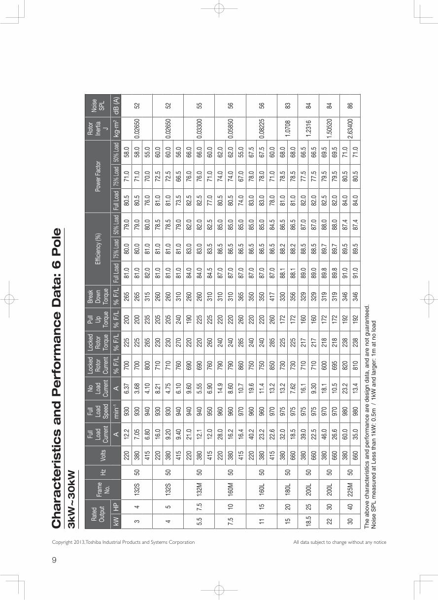
3kW
~3
0kW
Rate
d Ou
tput
Fram
e No
.Hz
Volts
Full
Load
Cu
rrent
Full
Load
Sp
eed
No
Load
Cu
rrent
Lock
ed
Roto
r Cu
rrent
Lock
ed
Roto
r To
rque
Pull
Up
Torq
ue
Brea
k Do
wn
Torq
ueEf
ficien
cy (%
)Po
wer F
acto
rRo
tor
Iner
tia
J
Noise
SP
L
kWH
PA
min
-1A
% F
/L%
F/L
% F
/L%
F/L
Full L
oad
75%
Load
50%
Load
Full L
oad
75%
Load
50%
Load
kg·m
2dB
(A)
34
132S
50
220
12.2
930
6.37
700
225
200
265
81.0
80.0
79.0
80.5
71.0
58.0
0.02
650
5238
07.
0593
03.
6870
022
520
026
581
.080
.079
.080
.571
.058
.0
415
6.80
940
4.10
800
265
235
315
82.0
81.0
80.0
76.0
70.0
55.0
45
132S
50
220
16.0
930
8.21
710
230
205
260
81.0
81.0
78.5
81.0
72.5
60.0
0.02
650
5238
09.
2093
04.
7571
023
020
526
081
.081
.078
.581
.072
.560
.0
415
9.40
940
6.10
760
270
240
310
81.0
81.0
79.0
73.5
66.5
56.0
5.5
7.5
132M
50
220
21.0
940
9.60
690
220
190
260
84.0
83.0
82.0
82.5
76.0
66.0
0.03
300
5538
012
.194
05.
5569
022
022
526
084
.083
.082
.082
.576
.066
.0
415
12.0
950
6.90
760
260
225
310
84.5
83.5
82.5
77.0
71.0
60.0
7.5
1016
0M50
220
28.0
960
14.9
790
240
220
310
87.0
86.5
85.0
80.5
74.0
62.0
0.05
850
5638
016
.296
08.
6079
024
022
031
087
.086
.585
.080
.574
.062
.0
415
16.4
970
10.7
860
285
260
365
87.0
86.5
85.0
74.0
67.0
55.0
1115
160L
50
220
40.2
960
19.6
750
240
220
350
87.0
86.5
85.0
83.0
78.0
67.5
0.08
225
5638
023
.296
011
.475
024
022
035
087
.086
.585
.083
.078
.067
.5
415
22.6
970
13.2
850
285
260
417
87.0
86.5
84.5
78.0
71.0
60.0
1520
180L
5038
032
.097
513
.273
022
517
233
088
.188
.286
.581
.078
.568
.01.
0708
8366
018
.597
57.
6273
022
517
235
688
.188
.286
.581
.078
.568
.0
18.5
2520
0L50
380
39.0
975
16.1
710
217
160
329
89.0
88.5
87.0
82.0
77.5
66.5
1.23
1684
660
22.5
975
9.30
710
217
160
329
89.0
88.5
87.0
82.0
77.5
66.5
2230
200L
5038
046
.097
018
.160
021
817
231
989
.889
.788
.082
.579
.569
.51.
5052
084
660
26.6
970
10.5
695
218
172
319
89.8
89.7
88.0
82.0
79.5
69.5
3040
225M
5038
060
.098
023
.282
023
819
234
691
.089
.587
.484
.080
.571
.02.
6340
086
660
35.0
980
13.4
810
238
192
346
91.0
89.5
87.4
84.0
80.5
71.0
The
abo
ve c
hara
cter
istic
s an
d pe
rfor
man
ce a
re d
esig
n da
ta, a
nd a
re n
ot g
uara
ntee
d.N
oise
SP
L m
easu
red
at L
ess
than
1kW
: 0.5
m /
1kW
and
larg
er: 1
m a
t no
load

10
Copyright 2013, Toshiba Industrial Products and Systems Corporation All data subject to change without any notice
Characteristics & Performance Data at 60Hz operation
Pole Capacity (HP) Voltage (V) Frequency (Hz) Frame No
Current (A) Speed (min-1) Efficiency (%) Power Factor (%)
60Hz 60Hz 60Hz 60Hz
220V 440V 220V 440V 220V 440V 220V 440V
2
0.5
220/380/415
50
71M 1.60 0.85 3400 3420 69.5 72.0 88.0 82.01 80M 3.00 1.50 3460 3480 74.5 76.5 91.0 86.02 90L 5.60 2.80 3420 3430 79.0 80.0 90.0 88.53 90L 7.90 4.00 3430 3440 81.0 83.0 91.0 88.05 112M 13.7 6.90 3420 3430 82.5 84.0 93.0 91.0
7.5 132S 18.6 9.40 3460 3480 84.4 85.8 93.0 90.010 132S 24.6 12.4 3500 3510 87.0 88.5 92.0 87.015 160M 36.0 18.1 3490 3500 87.0 88.3 93.0 90.520 160M 48.0 24.0 3500 3520 89.5 90.4 93.5 91.025 160L 59.0 29.5 3500 3500 90.2 90.2 92.0 92.030
380/660
180M - 36.0 - 3530 - 89.6 - 91.040 200L - 48.0 - 3540 - 90.7 - 92.050 200L - 59.0 - 3550 - 91.9 - 90.560 200L - 72.0 - 3550 - 92.0 - 90.0
4
0.5
220/380/415
50
71M 1.80 1.00 1700 1720 74.0 73.0 75.5 69.01 80M 3.20 1.70 1720 1730 77.0 79.5 82.0 75.02 90L 5.70 3.00 1700 1720 79.0 81.5 88.0 81.03 100L 8.00 4.30 1700 1720 81.4 82.2 89.0 82.05 112M 14.7 7.90 1710 1720 82.5 84.0 87.0 80.0
7.5 132S 20.0 10.0 1720 1740 86.0 87.7 85.5 82.510 132M 27.0 13.6 1730 1740 87.6 88.0 85.0 82.515 160M 37.4 18.8 1730 1740 88.8 90.0 87.0 86.020 160L 50.6 25.8 1730 1740 90.0 91.0 88.5 85.025
380/660
180M - 37.0 - 1450 - 89.9 - 86.030 180L - 44.0 - 1450 - 90.5 - 85.540 200L - 60.0 - 1460 - 91.5 - 86.550 225S - 72.0 - 1460 - 92.0 - 87.560 225M - 88.0 - 1460 - 91.8 - 88.5
6
0.5
220/380/415
50
80M 1.80 1.00 1700 1720 74.0 73.0 75.5 69.01 90L 3.20 1.70 1720 1730 77.0 79.5 82.0 75.02 100L 5.70 3.00 1700 1720 79.0 81.5 88.0 81.03 112M 8.00 4.30 1700 1720 81.4 82.2 89.0 82.05 132S 14.7 7.90 1710 1720 82.5 84.0 87.0 80.0
7.5 132M 20.0 10.0 1720 1740 86.0 87.7 85.5 82.510 160M 27.0 13.6 1730 1740 87.6 88.0 85.0 82.515 160L 37.4 18.8 1730 1740 88.8 90.0 87.0 86.020
380/660
180L 50.6 25.8 1730 1740 90.0 91.0 88.5 85.025 200L - 37.0 - 1450 - 89.9 - 86.030 200L - 44.0 - 1450 - 90.5 - 85.540 225M - 60.0 - 1460 - 91.5 - 86.5
The above characteristics and performance are design data, and are not guaranteed.Noise SPL measured at Less than 1kW: 0.5m / 1kW and larger: 1m at no load

11
Copyright 2013, Toshiba Industrial Products and Systems Corporation All data subject to change without any notice
Mechanical Design
Name Plate Information
Terminal Box Vibration mm/sec (RMS)
Frame Size Protection of Degree
Rotation of terminal box
Terminal box material
Terminal bus
Conduct Hole Size
(mm2)Frame No. 2 Pole 4 Pole
71M IP55 4 x 90° Steel M4 φ18 71M 1.6 1.6
80M IP55 4 x 90° Steel M4 φ18 80M 1.6 1.6
90L IP55 4 x 90° Steel M4 φ18 90L 1.6 1.6
100L IP55 4 x 90° Steel M4 φ18 100L 1.6 1.6
112M IP55 4 x 90° Steel M4 φ18 112M 1.6 1.6
132S IP55 4 x 90° Steel M5 φ32 132S 1.6 1.6
132M IP55 4 x 90° Steel M5 φ32 132M 1.6 1.6
160M IP55 4 x 90° Steel M5 φ32 160M 2.2 2.2
160L IP55 4 x 90° Steel M5 φ32 160L 2.2 2.2
180M IP55 4 x 90° Steel M6 φ24 180M 2.2 2.2
180L IP55 4 x 90° Steel M6 φ24 180L 2.2 2.2
200L IP55 4 x 90° Steel M8 φ28 200L 2.2 2.2
225S IP55 4 x 90° Steel M8 φ28 225S 2.2 2.2
225M IP55 4 x 90° Steel M8 φ28 225M 2.2 2.2
RATED OUTPUT HP (kW) TYPE AND FORM
RATED SPEED PROTECTION OF DEGREE
RATED FREQUENCY THERMAL. CLASS
EFFICIENCY CONNECTION
STANDARD MANUFACTUING YEAR
RATED VOLTAGE FRAME NO.
POWER FACTOR TYPE OF CURRENT
RATED CURRENT DUTY TYPE
MAXIMUM AMBIENT TEMPRETURE BEARING NO (LS/OS)
SERIAL NO
銘板イメージ図.pdf 1 13/08/13 9:21
銘板イメージ図.pdf 1 13/08/13 9:21
12
Copyright 2013, Toshiba Industrial Products and Systems Corporation All data subject to change without any notice
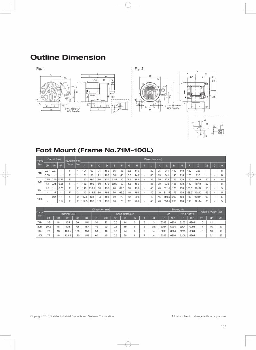
Outline Dimension
Foot Mount (Frame No.71M~100L)
Frame No
Output (kW)Insulation
ClassFig No
Dimension (mm)
2P 4P 6P A B C D E F G H I J K L M N R Z XB O JK
71M0.37 0.37 - F 1 121 90 71 150 56 45 2.3 146 - 30 25 241 140 110 120 7x8 - - 8
0.55 - - F 1 121 90 71 150 56 45 2.3 146 - 30 25 241 140 110 120 7x8 - - 8
80M0.75 0.55 0.37 F 1 133 100 80 170 62.5 50 4.5 165 - 35 30 273 165 130 140 8x10 50 - 8
1.1 0.75 0.55 F 1 133 100 80 170 62.5 50 4.5 165 - 35 30 273 165 130 140 8x10 50 - 8
90L1.5 1.1 0.75 F 2 143 118.5 90 198 70 62.5 10 190 - 40 40 311.5 176 150 168.5 10x12 56 - 5
- 1.5 - F 2 143 118.5 90 198 70 62.5 10 190 - 40 40 311.5 176 150 168.5 10x12 56 - 5
100L- 2.2 1.1 F 2 157.5 133 100 198 80 70 12 200 - 40 46 350.5 200 168 193 12x14 63 - 5
- 1.5 F 2 157.5 133 100 198 80 70 12 200 - 40 46 350.5 200 168 193 12x14 63 - 5
Frame No
Dimension (mm) Bearing NoApprox Weight (kg)
Terminal Box Shaft dimension 2P 4P & Above
KA KD KE KG KL Q QK QR S W T U L.S O.S L.S O.S 2P 4P 6P
71M 35 18 125 30 151 30 22 0.5 14 5 5 3 6203 6203 6203 6203 10 12
80M 27.5 18 130 42 157 40 32 0.5 19 6 6 3.5 6204 6204 6204 6204 14 16 17
90L 77 18 123.5 120 159 50 40 0.5 24 8 7 4 6205 6304 6205 6304 16 16 18
100L 77 18 123.5 120 159 60 45 0.5 28 8 7 4 6206 6304 6206 6304 21 25
Fig. 1 Fig. 2
M
JK
Z
E KE
KL
15°
ゴム口径(φKD)HOLE(φKD)
DL
A RB Q
QK
QR
K XBF FN
KA
J
G KG
C
Z
H
E
M
JK
Z
E KE
KL
15°
ゴム口径(φKD)HOLE(φKD)
DL
A RB Q
QK
QR
K XBF FN
KA
J
G KG
C
Z
H
E
M
ZJK
EKE
KL
ゴム口径(φKD)HOLE(φKD)
D
LA R
B Q
QK
QR
KXBF F
N
KA
J
G
KG
Z
C
H
E
L
A
RB Q
QK
QR
XBFN
KF
4-φZ穴
EJ
G
CKE
HI
EM
DKL ゴム口径φKD
S
W
T U
4-φZ穴
EJ
G
CKE
HI
EM
Dゴム口径φKD
F XB
QR
QK
QBR
L
A
FK
N
M
ZJK
EKE
KL
ゴム口径(φKD)HOLE(φKD)
D
LA R
B Q
QK
QR
KXBF F
N
KA
J
G
KG
Z
C
H
E

13
Copyright 2013, Toshiba Industrial Products and Systems Corporation All data subject to change without any notice
Outline Dimension
Foot Mount (Frame No.112M~160L)
Frame No
Output (kW)Insulation
ClassFig No
Dimension (mm)
2P 4P 6P A B C D E F G H I J K L M N R Z XB O JK
112M3 3.0 2.2 F 3 186 140 112 214 95 70 12 - 261 40 46 386 220 168 200 12x14 70 - 5
4 4.0 F 3 186 140 112 214 95 70 12 - 261 40 46 386 220 168 200 12x14 70 - 5
132S5.5 5.5 3.0 F 3 210.5 159 132 252 108 70 15 - 303 50 50 449.5 260 175 239 12x14 89 - 5
7.5 4.0 F 3 210.5 159 132 252 108 70 15 - 303 50 50 449.5 260 175 239 12x14 89 - 5
132M 7.5 5.5 F 3 229.5 178 132 252 108 89 15 - 303 50 50 487.5 260 213 258 12x14 89 - 5
160M11 11 7.5 F 3 302 213 160 304 127 105 18 - 351 60 60 625 308 250 323 14.5x18.5 108 - 5
15 F 3 302 213 160 304 127 105 18 - 351 60 60 625 308 250 323 14.5x18.5 108 - 5
160L 18.5 15 11 F 3 280 235 160 304 127 127 18 - 351 60 60 625 308 294 345 14.5x18.5 108 - 5
Frame No
Dimension (mm) Bearing NoApprox Weight (kg)
Terminal Box Shaft dimension 2P 4P & Above
KA KD KE KG KL Q QK QR S W T U L.S O.S L.S O.S 2P 4P 6P
112M 77 18 130.5 142 166 60 45 1.5 28 8 7 4 6207 6305 6207 6305 26 27 29
132S 129 32 178.5 167 240 80 63 0.5 38 10 8 5 6308 6306 6308 6306 41 42 54
132M 128 32 178.5 167 240 80 63 0.5 38 10 8 5 6308 6306 6308 6306 43 48 60
160M 128 32 199.5 205 259 110 90 2 42 12 8 5 6310 6208 6310 6208 70 77 88
160L 129 32 199.5 205 259 110 90 2 42 12 8 5 6310 6208 6310 6208 92 92 106
Fig. 3
ME
KE
KL
ゴム口径(φKD)HOLE(φKD)
取付脚裏面 詳細図Detail of Mounting foot
D LA R
B QQK
QR
KXBF F
N
KA
J
ZJK
G
KG
C
Z
HI
E
L
A
RB Q
QK
QR
XBFN
KF
4-φZ穴
EJ
G
CKE
HI
EM
DKL ゴム口径φKD
S
W
T U
4-φZ穴
EJ
G
CKE
HI
EM
Dゴム口径φKD
F XB
QR
QK
QBR
L
A
FK
N
M
ZJK
EKE
KL
ゴム口径(φKD)HOLE(φKD)
D
LA R
B Q
QK
QR
KXBF F
N
KA
J
G
KG
Z
C
H
E

14
Copyright 2013, Toshiba Industrial Products and Systems Corporation All data subject to change without any notice
Foot Mount (Frame No.180M~225SM)
Frame No
Output (kW)Insulation
ClassFig No
Dimension (mm)
2P 4P 6P A B C D E F G H I J K L M N R Z XB O JK
180M 22 18.5 - F 4 320 235.5 180 480 139.5 120.5 20 370 450 60 82.5 671.5 324 286 351.5 14.5 121 - -
180L - 22 15 F 5 339 254.5 180 382 139.5 139.5 20 370 450 60 82.5 709.5 324 324 370.5 14.5 121 - -
200L30
3018.5
F 5 374 279.5 200 407 159 152.5 20 410 511.5 80 80 769.5 378 360 395.5 18.5 133 - -37 22
225S - 37 - F 5 380.5 296 225 464 178 143 22 460 561.5 80 120 825 416 366 444.5 18.5 149 - -
225M 45 - - F 5 380.5 296 225 464 178 155.5 22 460 561.5 80 120 795 416 366 414.5 18.5 149 - -
225M - 45 30 F 5 380.5 296 225 464 178 155.5 22 460 561.5 80 120 825 416 366 444.5 18.5 149 - -
Frame No
Dimension (mm) Bearing NoApprox Weight (kg)
Terminal Box Shaft dimension 2P 4P & Above
KA KD KE KG KL Q QK QR S W T U L.S O.S L.S O.S 2P 4P 6P
180M - 24 222.5 - 107.5 110 90 1.5 48 14 9 5.5 6310 6210 6310 6210 178 175 175
180L - 24 222.5 - - 110 90 1.5 48 14 9 5.5 - - 6310 6210 - 191 191
200L - 28 244 - 142.5 110 90 1.5 55 16 10 6 6312 6312 - - 264 283 253
225S - 28 269 - 142.5 140 110 1.5 60 18 11 7 - - 6315 6312 - 314 -
225M - 28 269 - 142.5 110 90 1.5 55 16 10 6 6312 6312 - - 314 - -
225M - 28 269 - 142.5 140 110 1.5 60 18 11 7 - - 6315 6312 - 331 335
Outline DimensionFig. 4 Fig. 5
L
A
RB Q
QK
QR
XBFN
KF
4-φZ穴
EJ
G
CKE
HI
EM
DKL ゴム口径φKD
S
W
T U
4-φZ穴
EJ
G
CKE
HI
EM
Dゴム口径φKD
F XB
QR
QK
QBR
L
A
FK
N
L
A
RB Q
QK
QR
XBFN
KF
4-φZ穴
EJ
G
CKE
HI
EM
DKL ゴム口径φKD
S
W
T U
4-φZ穴
EJ
G
CKE
HI
EM
Dゴム口径φKD
F XB
QR
QK
QBR
L
A
FK
N
L
A
RB Q
QK
QR
XBFN
KF
4-φZ穴
EJ
G
CKE
HI
EM
DKL ゴム口径φKD
S
W
T U
4-φZ穴
EJ
G
CKE
HI
EM
Dゴム口径φKD
F XB
QR
QK
QBR
L
A
FK
N

15
Copyright 2013, Toshiba Industrial Products and Systems Corporation All data subject to change without any notice
Flange Mount (Frame No.71M~112M)
Flange No
Output (kW) Frame No
Insulation Class
Fig No
Dimension (mm)
D IE IL L LL LRTerminal Box
2P 4P 6P KA KD KE KL KG
FF1300.37 0.37
71M F 1 150 - - 261 231 30 - 18 105 147 73.50.55
FF1650.75 0.55 0.37
80M F 1 170 - - 273 233 40 - 18 129 159 56.51.1 0.75 0.55
FF1651.5 1.1 0.75
90L F 2 198 - - 325 275 50 - 18 117.5 153 86.52.2 1.5
FF2153.0 2.2 1.1
100L F 2 198 - - 350.5 290.5 60 - 18 117.5 153 102.54.0 1.5
FF2155.5 3.0 2.2
112M F 2 214 - 140 386 326 60 - 18 129 164 119.57.5 4.0
Flange No
Dimension (mm) Bearing NoApprox Weight (kg)
Flange Shaft dimension 2P 4P & Above
LA LB LC LE LG LN LZ Q QK QR S W T U L.S O.S L.S O.S 2P 4P 6P
FF130 130 110 160 3.5 9 4 10 30 22 1.3 14 5 5 3 6203 6203 6203 6203 11 12 12
FF165 165 130 200 3.5 10 4 12 40 32 0.5 19 6 6 3.5 6204 6204 6204 6204 16 16 14.4
FF165 165 130 200 3.5 10 4 12 50 40 0.5 24 8 7 4 6205 6304 6205 6304 18 17.5 18
FF215 215 180 250 4 11 4 14.5 60 45 0.5 28 8 7 4 6206 6304 6206 6304 28 23 25
FF215 215 180 250 4 12 4 14.5 60 45 1.5 28 8 7 4 6207 6305 6207 6305 45 29 29
Outline DimensionFig. 1 Fig. 2
QR
QQK
LRKG145LL L
LGLE
φLCφLB
φD 15°
45°
45°
KL
ゴム口径(φKD)HOLE(φKD)
φLN-φLZ 穴
φLA
HOLE
KL
KEQ
R
Q
QK
LR KG 145LLL
LGLE
φLCφLB φD
15°
45°
45°
KL
ゴム口径(φKD)
HOLE(φKD)
φLN-φLZ穴
φLA
HOLE
KLKE
Q
QK
LRKG
LLL
LGLE
φLCφLB
φD
45°
45°
ゴム口径(φKD)HOLE(φKD)
LN-φLZ 穴
φLA
HOLE
KL
KE
Q
QK
LRKG
LLL
LGLE
φLCφLB
φD
45°
45°
ゴム口径(φKD)
HOLE(φKD)
LN-φLZ穴
φLA
HOLE
KLKE
U
T
S
W

16
Copyright 2013, Toshiba Industrial Products and Systems Corporation All data subject to change without any notice
Flange Mount (Frame No.132S~160L)
Flange No
Output (kW) Frame No
Insulation Class
Fig No
Dimension (mm)
D IE IL L LL LRTerminal Box
2P 4P 6P KA KD KE KL KG
FF2655.5 3
132S F 2 252 151 149 449.5 369.5 80 - 32 178.5 240 904
FF265 11 7.5 5.5 132M F 2 252 151 178 487.5 407.5 80 - 32 178.5 240 128
FF300 15 11 7.5 160M F 3 313 170 213 603 493 110 - 32 199.5 259 85
FF300 18.5 15 11 160L F 3 313 170 235 625 515 110 - 32 199.5 259 107
Flange No
Dimension (mm) Bearing NoApprox Weight (kg)
Flange Shaft dimension 2P 4P & Above
LA LB LC LE LG LN LZ Q QK QR S W T U L.S O.S L.S O.S 2P 4P 6P
FF265 265 230 300 4 14 4 14.5 80 63 0.5 38 10 8 5 6308 6306 6308 6306 47 45 54
FF265 265 230 300 4 14 4 14.5 80 63 0.5 38 10 8 5 6308 6306 6308 6306 77 51 60
FF300 300 250 350 5 14 4 18.5 110 90 2 42 12 8 5 6310 6208 6310 6208 89 84 88
FF300 300 250 350 5 14 4 18.5 110 90 2 42 12 8 5 6310 6208 6310 6208 99 99 106
Outline DimensionFig. 3
QQK LR
KG
LLIL
L
LGLE
φLC
φLB
QR
φDIE
45°
45°
KA ゴム口径(φKD)HOLE(φKD)
LN-φLZ 穴
φLA
HOLE
KL
KE
QQK
LR
KG
LLIL
L
LGLE
φLC
φLB
QR φD
IE
45°
45°
KAゴム口径(φKD)
HOLE(φKD)
LN-φLZ穴
φLA
HOLE
KLKE
U
T
S
W

17
Copyright 2013, Toshiba Industrial Products and Systems Corporation All data subject to change without any notice
Flange Mount (Frame No.180M~225SM)
Flange No
Output (kW) Frame No
Insulation Class
Fig No
Dimension (mm)
D IE IL L LL LRTerminal Box
2P 4P 6P KA KD KE KL KG
FF300 22 18.5 - 180M F 1 373 240 241.5 671.5 561.5 110 - 24 219 266.5 163
FF300 - 22 15 180L F 1 373 240 260.5 709.5 599.5 110 - 24 219 266.5 182
FF35030
3018.5
200L F 1 410 260 285.5 769.5 659.5 110 - 28 239 306.5 186.537 22
FF400 37 - 225S F 1 456 287 304 825 685 140 - 28 259 326.5 205.5
FF400 45 45 30 225M F 1 456 287 304 825 685 140 - 28 259 326.5 205.5
Flange No
Dimension (mm) Bearing NoApprox Weight (kg)
Flange Shaft dimension 2P 4P & Above
LA LB LC LE LG LN LZ Q QK QR S W T U L.S O.S L.S O.S 2P 4P 6P
FF300 300 250 350 5 15 4 18.5 110 90 1.5 48 14 9 5.5 6310 6210 6310 6210 203 200 -
FF300 300 250 350 5 15 4 18.5 110 90 1.5 48 14 9 5.5 - - 6310 6210 - 218 218
FF350 350 300 400 5 19 4 18.5 110 90 1.5 55 15 10 6 6312 6312 6312 6312275
294266
300 284
FF400 400 350 450 5 22 8 18.5 140 110 1.5 60 18 11 7 6315 6312 6315 6312 - 357 -
FF400 400 350 450 5 22 8 18.5 140 110 1.5 60 18 11 7 - - 6315 6312 360 374 361
Outline DimensionFig. 4
QQK LR
KG
LLL
LG
ILLE
φLCφLB
QR
IE
φD
45°
22.5°KLKE
ゴム口径(φKD)HOLE(φKD)
LN-φLZ
φLA
HOLE
QQK
LR
KG
LLL
LG
ILLE
φLCφLB
QR
IE
φD
45°
22.5°KL KE
ゴム口径(φKD)
HOLE(φKD)
LN-φLZ
φLA
HOLE
UT
S
W

18
Copyright 2013, Toshiba Industrial Products and Systems Corporation All data subject to change without any notice
Memo

TOSHIBA contacts in South East Asia
Toshiba Asia Pacific Pte., Ltd.• Singapore – Head Quarters20 Pasir Panjang Road, #13-27/28 Mapletree Business City, Singapore 117439Tel: (65) 6297-0990, DID: (65) 6305 5515 Fax: 6305-5560
• Kuala LumpurNo.1-2, The Boulevard Mid Valley City, Lingkaran Syed Putra, 59200 Kuala Lumpur, MalaysiaTel: (603) 2284-6222 Fax: (603) 2288-1952
• Jakarta16th Floor Summitmas Tower,Jl. Jenderal Sudirman, KAV.61-62, Jakarta, 12190 IndonesiaTel: (6221) 520-0754 Fax: (6221) 520-0774
• Ho Chi Minh CityUnit 1702,17th Floor, Centec Building 72-74 Nguyen Thi Minh Khai, District 3, Ho chi Minh City, VietnamTel: (848) 3827-4560 Fax: (848) 3827-4564
Toshiba Asia Pacific (Thailand) Co, Ltd.946 Dusit Thani Bldg., 10Fl., Rm. 1002, Rama IV Rd., Silom , Bangrak, BKK 10500Tel: (66) 2637-5124 to 27 Fax: (66) 2637-5128
Toshiba (Philippines), Inc.Infrastructure Systems Division & Corporate Liaison Office 42nd Floor GT Tower International, 6813 Ayala Avenue, Makati City 1226Tel: (63) 2-819-1048 Fax: (63) 2-819-5479
2013-08
Copyright 2013, Toshiba Industrial Products and Systems Corporation
Toshiba Industrial Products and Systems Corporation9-11, Nihonbashi-honcho 4 Chome, Chuo-Ku, Tokyo 103-0023 JapanTel: +81-3-5644-5509 Fax: +81-3-5644-5519
Distributed by:
Manufactured by : TOSHIBA DALIAN CO., LTD.
Precautions* Please read the instruction manual before installing or operating motor.
* This product is intended for general purpose uses in industrial application. It cannot be used applications where may cause big impact on public uses, such as power plant and railway, and equipment which endanger human life or injury, such as nuclear power control, aviation, space flight control, traffic, safety device, amusement, or medical. It may be considerable whether to apply, under the special condition or an application where strict quality control may not be required. Please contact our headquarters, branch, or local offices printed on the front and back covers of this catalogue.
* When exporting Toshiba motors separately or combined with your equipment, please be sure to satisfy the objective conditions and inform conditions listed in the export control policies, so called Catch All restrictions, which are set by the Ministry of Economy, Trade and Industry of Japan, and the appropriate export procedures must also be taken.
* Please use our product in applications where do not cause serious accidents or damages even if product is failure, or please use in environment where safety equipment is applicable or a backup circuit device is provided outside the system.
* None of Toshiba, its subsidiaries, affiliates or agents, shall be liable for any physical damages, including, without limitation, malfunction, anomaly, breakdown or any other problem that may occur to any apparatus in which the Toshiba motor is incorporated or to any equipment that is used in combination with the Toshiba motor. Nor shall Toshiba, its subsidiaries, affiliates or agents be liable for any compensatory damages resulting from such utilization, including compensation for special, indirect, incidental, consequential, punitive or exemplary damages, or for loss of profit, income or data, even if the user has been advised or apprised of the likelihood of the occurrence of such loss or damages.