Torsiflex-i Disc Couplings for General Purpose Applications · • Compliance with API 671 / ISO...
8
Altra Industrial Motion Torsiflex-i Disc Couplings for General Purpose Applications Now Available With Torsi-Lock ® Hubs
Transcript of Torsiflex-i Disc Couplings for General Purpose Applications · • Compliance with API 671 / ISO...

A l t r a I n d u s t r i a l M o t i o n
Torsiflex-i Disc Couplings for General Purpose Applications
Now
Available With
Torsi-Lock®
Hubs

A l t r a C o u p l i n g s I T o r s i f l e x - i D i s c C o u p l i n g s f o r G e n e r a l P u r p o s e A p p l i c a t i o n s
Torsiflex-i Disc CouplingsSpecifically designed for the process pumpand general industrial markets.
• Standard coupling is fully compliant with the requirements of API 610 / ISO 14691
• Plug-in spacer design allows installation and removal without disturbing the hubs
• Inch series hub attachment screws (Metric available upon request)
• Robust disc pack design allows for greater torque load in a smaller coupling, resulting in lower weight
• Large bolts for high clamp load, increasing frictional torque load, and reduced bolt bending stress
• Max bores matched to NEMA motor shafts, resulting in up to 60% weight savings per application
• Smaller diameter and lower weight per HP provide better inherent balance
• ATEX compliance is standard — Exll 2GDc135degC(T4)
• Built-in Anti-Flail Feature
• Zinc Phosphate coating standard
• Large hubs available on first two sizes
• Compliance with API 671 / ISO 10441 is available
The following standard materials of construction are used in the Torsiflex-i range. Alternative materials are available for special applications and are available on request.
Hubs: Carbon Steel
Spacers: Carbon Steel
Adapters: Carbon Steel
Discs: Stainless Steel (301)
Bolts: Alloy Steel
Nuts: Alloy steel
Overload Collars: High strength ‘non-sparking’ material
ATEX Approval Certificate No. SIRA 03ATEX205
Materials
Advantages
• Torsiflex-i couplings consist of 2 hubs and a factory assembled transmission unit. Installation involves fitting the hubs to the machinery shaft ends, introducing the transmission unit, then securing with the attachment screws
• MAXIMUM SPEEDS shown are for standard materials. When higher speeds are required please consult Ameridrives Couplings or Bibby Transmissions.
• PEAK TORQUE of 1.75 and MOMENTARY TORQUE of 2.7 times the stated ratings are accepted
• SPARK FREE overload protection is provided as a standard feature on all Torsiflex-i couplings, making them suitable for GAS ZONE environments
• STANDARD COUPLINGS are designed for general purpose applications and are suitable for the majority of process pump, fan, and compressors applications
• SPECIAL COUPLING versions available include: - Torque overload protection- Limited end float- Electrical Insulation- Bolted adapters suitable for high cyclic torques
Features
2
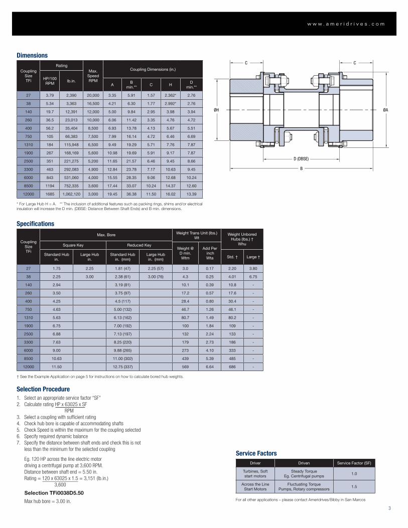
Selection Procedure1. Select an appropriate service factor “SF”2. Calculate rating HP x 63025 x SF
RPM3. Select a coupling with sufficient rating4. Check hub bore is capable of accommodating shafts5. Check Speed is within the maximum for the coupling selected6. Specify required dynamic balance7. Specify the distance between shaft ends and check this is not
less than the minimum for the selected coupling
Eg. 120 HP across the line electric motor driving a centrifugal pump at 3,600 RPM. Distance between shaft end = 5.50 in.Rating = 120 x 63025 x 1.5 = 3,151 (lb.in.) 3,600
Selection TFi0038D5.50
Max hub bore = 3.00 in.
C C
D (DBSE)
B
ØH ØA
ØdwTORSILOC
SIZEØHt
ALLOW SPACE FORTORQUE WRENCH
L1
L1
Ct D (DBSE)
Service FactorsDriver Driven Service Factor (SF)
Turbines, Soft start motors
Steady Torque Eg. Centrifugal pumps
1.0
Across the Line Start Motors
Fluctuating Torque Pumps, Rotary compressors
1.5
For all other applications – please contact Ameridrives/Bibby in San Marcos
Dimensions
Coupling Size TFi
RatingMax.
Speed RPM
Coupling Dimensions (in.)
HP/100 RPM
lb.in.A
Bmin.**
C HD
min.**
27 3.79 2,390 20,000 3.35 5.91 1.57 2.362* 2.76
38 5.34 3,363 16,500 4.21 6.30 1.77 2.992* 2.76
140 19.7 12,391 12,000 5.00 9.84 2.95 3.98 3.94
260 36.5 23,013 10,000 6.06 11.42 3.35 4.76 4.72
400 56.2 35,404 8,500 6.93 13.78 4.13 5.67 5.51
750 105 66,383 7,500 7.99 16.14 4.72 6.46 6.69
1310 184 115,948 6,500 9.49 19.29 5.71 7.76 7.87
1900 267 168,169 5,600 10.98 19.69 5.91 9.17 7.87
2500 351 221,275 5,200 11.65 21.57 6.46 9.45 8.66
3300 463 292,083 4,900 12.84 23.78 7.17 10.63 9.45
6000 843 531,060 4,000 15.55 28.35 9.06 12.68 10.24
8500 1194 752,335 3,600 17.44 33.07 10.24 14.37 12.60
12000 1685 1,062,120 3,000 19.45 36.38 11.50 16.02 13.39
* For Large Hub H = A. ** The inclusion of additional features such as packing rings, shims and/or electrical insulation will increase the D min. (DBSE: Distance Between Shaft Ends) and B min. dimensions.
Specifications
Coupling Size TFi
Max. Bore Weight Trans Unit (lbs.)Wt
Weight Unbored Hubs (lbs.) †
WhuSquare Key Reduced KeyWeight @
D min.Wtm
Add Per inchWta
Standard Hubin.
Large Hubin.
Standard Hubin. (mm)
Large Hubin. (mm)
Std. † Large †
27 1.75 2.25 1.81 (47) 2.25 (57) 3.0 0.17 2.20 3.80
38 2.25 3.00 2.38 (61) 3.00 (76) 4.3 0.25 4.01 6.75
140 2.94 3.19 (81) 10.1 0.39 10.8 -
260 3.50 3.75 (97) 17.2 0.57 17.6 -
400 4.25 4.5 (117) 28.4 0.80 30.4 -
750 4.63 5.00 (132) 46.7 1.26 46.1 -
1310 5.63 6.13 (162) 80.7 1.49 80.2 -
1900 6.75 7.00 (192) 100 1.84 109 -
2500 6.88 7.13 (197) 132 2.24 133 -
3300 7.63 8.25 (220) 179 2.73 186 -
6000 9.00 9.88 (265) 273 4.10 333 -
8500 10.63 11.00 (302) 439 5.39 485 -
12000 11.50 12.75 (337) 569 6.64 686 -
† See the Example Application on page 5 for instructions on how to calculate bored hub weights.
3
w w w . a m e r i d r i v e s . c o m

TFi Misalignment
CouplingSize TFi
Max. Angular Misalignment
(Deg.)
Bending Moment
(ft.lb./deg.)
Max. Axial Deflection (Zero
Angular Misalignment) (in.)
Max. Axial
Thrust (lbf.)
Max. Axial Deflection at full
Angular Misalignment (in.)
Axial Thrust (lbf.)
Point A (1) (2) (4) Point C (3) Point B (4)
Per Element Per Assembly
27 0.5 23 .067 126 .019 15
38 0.5 20 .087 112 .019 9
140 0.5 20 .106 287 .019 20
260 0.5 30 .130 542 .024 28
400 0.5 66 .169 917 .055 112
750 0.5 108 .197 1380 .071 202
1310 0.5 164 .236 1971 .087 292
1900 0.33 277 .197 2473 .059 337
2500 0.33 369 .212 2900 .067 337
3300 0.33 435 .236 3518 .071 405
6000 0.33 704 .295 5170 .094 607
8500 0.33 1025 .319 7531 .110 1124
12000 0.33 1261 .354 8587 .118 1124
Installation AlignmentRecommended Installation Alignments shown as % of the Maximum Permitted values for the Couplings
Allowable Angular / Radial Misalignment Allowable Axial Misalignment
20% Maximum 20% Maximum
Note: Angular / Radial as percentage of stated value for ‘Point A’. Axial as percentage of stated value for ‘Point C’.
Misalignment DataThese will be supplied upon request with any order. Guidelines are available for assessment at preliminary stages. The methods of machinery alignment vary accordingly to personal preference. Simple recommended methods are highlighted in our Installation Instructions which are available upon request. The following is a guide to acceptable misalignments at installation.
Note, however, that if machinery growths are known the values may be adjusted in the form of pre-deflection, etc. In addition, please note that the values shown here are MAXIMUM values. Reduction in these values will reduce bearing loads and improve the allowance for misalignment due to machinery settlement, etc. thus ensuring greater machinery life and trouble free operation of the coupling.
Definition of Misalignments Angular & Radial Misalignment in "Combination"
Angle 1Angle 2
Radial/ParallelRadial/Parallel
Axial Angular
Com
bin
ed A
ngul
ar/P
aral
lel M
isal
ignm
ent
Axial Deflection (±)
b
a
c C
A B
Allowable Misalignments for Disc Couplings
1. Combined angular/radial misalignment
2. 1 degree angle is equivalent to 0.017 in./in. radial misalignment
3. At zero speed (Static)
4. At maximum speed & continuous rated torque
A l t r a C o u p l i n g s I T o r s i f l e x - i D i s c C o u p l i n g s f o r G e n e r a l P u r p o s e A p p l i c a t i o n s
4
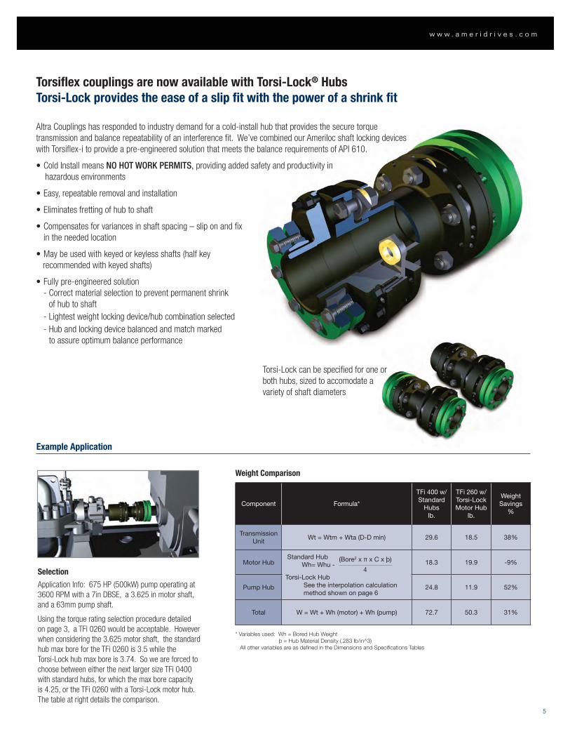
Torsiflex couplings are now available with Torsi-Lock® HubsTorsi-Lock provides the ease of a slip fit with the power of a shrink fit
Altra Couplings has responded to industry demand for a cold-install hub that provides the secure torque transmission and balance repeatability of an interference fit. We’ve combined our Ameriloc shaft locking devices with Torsiflex-i to provide a pre-engineered solution that meets the balance requirements of API 610.
•ColdInstallmeansNO HOT WORK PERMITS, providing added safety and productivity in hazardous environments
•Easy,repeatableremovalandinstallation
•Eliminatesfrettingofhubtoshaft
•Compensatesforvariancesinshaftspacing–sliponandfix in the needed location
•Maybeusedwithkeyedorkeylessshafts(halfkey recommended with keyed shafts)
•Fullypre-engineeredsolution - Correct material selection to prevent permanent shrink
of hub to shaft - Lightest weight locking device/hub combination selected - Hub and locking device balanced and match marked
to assure optimum balance performance
Torsi-Lock can be specified for one or both hubs, sized to accomodate a variety of shaft diameters
Example Application
Component Formula*
TFi 400 w/Standard
Hubslb.
TFi 260 w/Torsi-LockMotor Hub
lb.
Weight Savings
%
TransmissionUnit
Wt = Wtm + Wta (D-D min) 29.6 18.5 38%
Motor Hub Standard Hub Wh= Whu -
Torsi-Lock Hub See the interpolation calculation method shown on page 6
18.3 19.9 -9%
Pump Hub 24.8 11.9 52%
Total W = Wt + Wh (motor) + Wh (pump) 72.7 50.3 31%
* Variables used: Wh = Bored Hub Weight þ = Hub Material Density (.283 lb/in^3) All other variables are as defined in the Dimensions and Specifications Tables
Weight Comparison
(Bore2 x π x C x þ)
4Selection
Application Info: 675 HP (500kW) pump operating at 3600 RPM with a 7in DBSE, a 3.625 in motor shaft, and a 63mm pump shaft.
Using the torque rating selection procedure detailed on page 3, a TFi 0260 would be acceptable. However when considering the 3.625 motor shaft, the standard hub max bore for the TFi 0260 is 3.5 while the Torsi-Lock hub max bore is 3.74. So we are forced to choose between either the next larger size TFi 0400 with standard hubs, for which the max bore capacity is 4.25, or the TFi 0260 with a Torsi-Lock motor hub. The table at right details the comparison.
5
w w w . a m e r i d r i v e s . c o m
A l t r a C o u p l i n g s I T o r s i f l e x - i D i s c C o u p l i n g s f o r G e n e r a l P u r p o s e A p p l i c a t i o n s
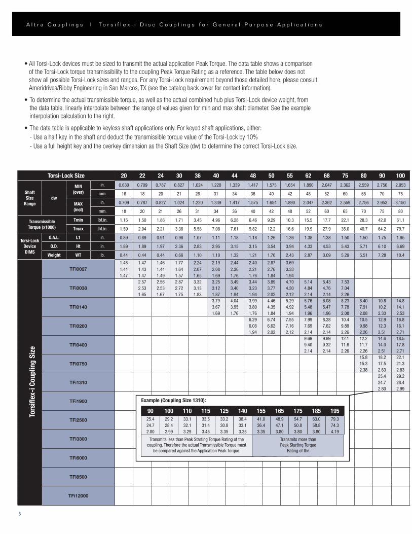
•AllTorsi-LockdevicesmustbesizedtotransmittheactualapplicationPeakTorque.Thedatatableshowsacomparisonof the Torsi-Lock torque transmissibility to the coupling Peak Torque Rating as a reference. The table below does not show all possible Torsi-Lock sizes and ranges. For any Torsi-Lock requirement beyond those detailed here, please consult Ameridrives/Bibby Engineering in San Marcos, TX (see the catalog back cover for contact information).
•Todeterminetheactualtransmissibletorque,aswellastheactualcombinedhubplusTorsi-Lockdeviceweight,fromthe data table, linearly interpolate between the range of values given for min and max shaft diameter. See the example interpolation calculation to the right.
•Thedatatableisapplicabletokeylessshaftapplicationsonly.Forkeyedshaftapplications,either: - Use a half key in the shaft and deduct the transmissible torque value of the Torsi-Lock by 10% - Use a full height key and the overkey dimension as the Shaft Size (dw) to determine the correct Torsi-Lock size.
20 22 24 30 36 40 44 48 50 55 62 68 75 80 90 1000.630 0.709 0.787 0.827 1.024 1.220 1.339 1.417 1.575 1.654 1.890 2.047 2.362 2.559 2.756 2.953
16 18 20 21 26 31 34 36 40 42 48 52 60 65 70 75
0.709 0.787 0.827 1.024 1.220 1.339 1.417 1.575 1.654 1.890 2.047 2.362 2.559 2.756 2.953 3.150
18 20 21 26 31 34 36 40 42 48 52 60 65 70 75 80
1.15 1.50 1.86 1.71 3.45 4.96 6.28 6.46 9.29 10.3 15.5 17.7 22.1 28.3 42.0 61.1
1.59 2.04 2.21 3.36 5.58 7.08 7.61 9.82 12.2 16.6 19.9 27.9 35.0 40.7 64.2 79.7
0.89 0.89 0.91 0.98 1.07 1.11 1.18 1.18 1.26 1.36 1.38 1.38 1.50 1.50 1.75 1.95
1.89 1.89 1.97 2.36 2.83 2.95 3.15 3.15 3.54 3.94 4.33 4.53 5.43 5.71 6.10 6.69
0.44 0.44 0.44 0.66 1.10 1.10 1.32 1.21 1.76 2.43 2.87 3.09 5.29 5.51 7.28 10.4
1.48 1.47 1.46 1.77 2.24 2.19 2.44 2.40 2.87 3.691.44 1.43 1.44 1.64 2.07 2.08 2.36 2.21 2.76 3.331.47 1.47 1.49 1.57 1.65 1.69 1.76 1.76 1.84 1.94
2.57 2.56 2.87 3.32 3.25 3.49 3.44 3.89 4.70 5.14 5.43 7.532.53 2.53 2.72 3.13 3.12 3.40 3.23 3.77 4.30 4.84 4.76 7.041.65 1.67 1.75 1.83 1.87 1.94 1.94 2.02 2.12 2.14 2.14 2.26
3.79 4.04 3.99 4.46 5.29 5.76 6.08 8.23 8.40 10.8 14.83.67 3.95 3.80 4.35 4.92 5.48 5.47 7.78 7.91 10.2 14.11.69 1.76 1.76 1.84 1.94 1.96 1.96 2.08 2.08 2.33 2.53
6.29 6.74 7.55 7.99 8.28 10.4 10.5 12.9 16.86.08 6.62 7.16 7.69 7.62 9.89 9.98 12.3 16.11.94 2.02 2.12 2.14 2.14 2.26 2.26 2.51 2.71
9.69 9.99 12.1 12.2 14.6 18.59.40 9.32 11.6 11.7 14.0 17.82.14 2.14 2.26 2.26 2.51 2.71
15.8 18.2 22.115.3 17.5 21.32.38 2.63 2.83
25.4 29.224.7 28.42.80 2.99
TFi0027
TFi0038
TFi0140
TFi0260
TFi0400
TFi0750
TFi1310
TFi1900
TFi2500
TFi3300
TFi6000
TFi8500
TFi12000
Tors
iflex
-i C
oupl
ing
Size
Transmits less than Peak Starting Torque Rating of the coupling. Therefore the actual Transmissible Torque must
be compared against the Application Peak Torque.
Transmits more than Peak Starting Torque
Rating of the
90 100 110 115 125 140 155 165 175 185 19525.4 29.2 33.1 33.5 33.2 38.4 41.0 48.9 54.7 63.0 79.324.7 28.4 32.1 31.4 30.8 33.1 36.4 47.1 50.8 58.8 74.32.80 2.99 3.29 3.45 3.35 3.35 3.35 3.80 3.80 3.80 4.19
Example (Coupling Size 1310):
6
Torsi-Lock Size
ShaftSize
Rangedw
MIN(over)
in.
mm.
MAX(incl)
in.
mm.
Transmissible Torque (x1000)
Tmin lbf.in.
Tmax lbf.in.
Torsi-LockDeviceDIMS
O.A.L. L1 in.
O.D. Ht in.
Weight WT lb.
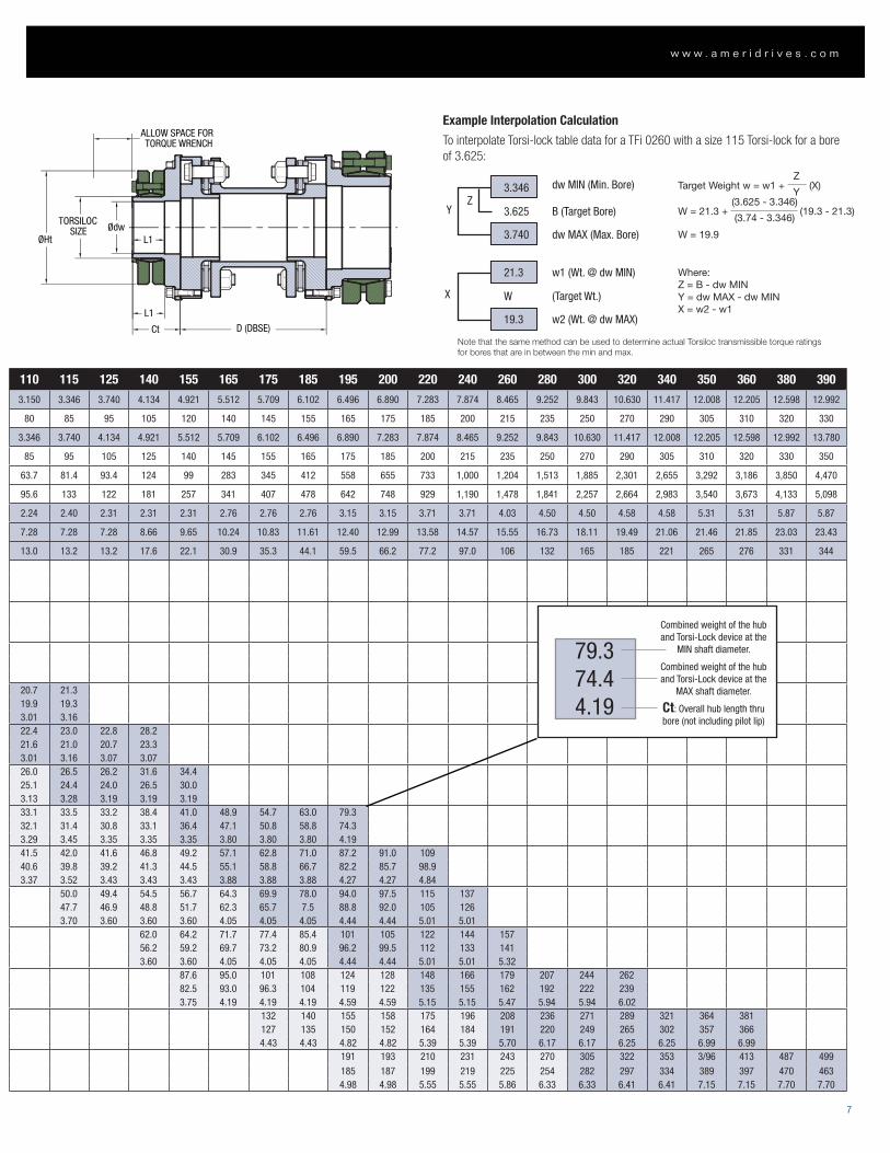
Example Interpolation Calculation
To interpolate Torsi-lock table data for a TFi 0260 with a size 115 Torsi-lock for a bore of 3.625:
110 115 125 140 155 165 175 185 195 200 220 240 260 280 300 320 340 350 360 380 3903.150 3.346 3.740 4.134 4.921 5.512 5.709 6.102 6.496 6.890 7.283 7.874 8.465 9.252 9.843 10.630 11.417 12.008 12.205 12.598 12.992
80 85 95 105 120 140 145 155 165 175 185 200 215 235 250 270 290 305 310 320 330
3.346 3.740 4.134 4.921 5.512 5.709 6.102 6.496 6.890 7.283 7.874 8.465 9.252 9.843 10.630 11.417 12.008 12.205 12.598 12.992 13.780
85 95 105 125 140 145 155 165 175 185 200 215 235 250 270 290 305 310 320 330 350
63.7 81.4 93.4 124 99 283 345 412 558 655 733 1,000 1,204 1,513 1,885 2,301 2,655 3,292 3,186 3,850 4,470
95.6 133 122 181 257 341 407 478 642 748 929 1,190 1,478 1,841 2,257 2,664 2,983 3,540 3,673 4,133 5,098
2.24 2.40 2.31 2.31 2.31 2.76 2.76 2.76 3.15 3.15 3.71 3.71 4.03 4.50 4.50 4.58 4.58 5.31 5.31 5.87 5.87
7.28 7.28 7.28 8.66 9.65 10.24 10.83 11.61 12.40 12.99 13.58 14.57 15.55 16.73 18.11 19.49 21.06 21.46 21.85 23.03 23.43
13.0 13.2 13.2 17.6 22.1 30.9 35.3 44.1 59.5 66.2 77.2 97.0 106 132 165 185 221 265 276 331 344
20.7 21.319.9 19.33.01 3.1622.4 23.0 22.8 28.221.6 21.0 20.7 23.33.01 3.16 3.07 3.0726.0 26.5 26.2 31.6 34.425.1 24.4 24.0 26.5 30.03.13 3.28 3.19 3.19 3.1933.1 33.5 33.2 38.4 41.0 48.9 54.7 63.0 79.332.1 31.4 30.8 33.1 36.4 47.1 50.8 58.8 74.33.29 3.45 3.35 3.35 3.35 3.80 3.80 3.80 4.1941.5 42.0 41.6 46.8 49.2 57.1 62.8 71.0 87.2 91.0 10940.6 39.8 39.2 41.3 44.5 55.1 58.8 66.7 82.2 85.7 98.93.37 3.52 3.43 3.43 3.43 3.88 3.88 3.88 4.27 4.27 4.84
50.0 49.4 54.5 56.7 64.3 69.9 78.0 94.0 97.5 115 13747.7 46.9 48.8 51.7 62.3 65.7 7.5 88.8 92.0 105 1263.70 3.60 3.60 3.60 4.05 4.05 4.05 4.44 4.44 5.01 5.01
62.0 64.2 71.7 77.4 85.4 101 105 122 144 15756.2 59.2 69.7 73.2 80.9 96.2 99.5 112 133 1413.60 3.60 4.05 4.05 4.05 4.44 4.44 5.01 5.01 5.32
87.6 95.0 101 108 124 128 148 166 179 207 244 26282.5 93.0 96.3 104 119 122 135 155 162 192 222 2393.75 4.19 4.19 4.19 4.59 4.59 5.15 5.15 5.47 5.94 5.94 6.02
132 140 155 158 175 196 208 236 271 289 321 364 381127 135 150 152 164 184 191 220 249 265 302 357 3664.43 4.43 4.82 4.82 5.39 5.39 5.70 6.17 6.17 6.25 6.25 6.99 6.99
191 193 210 231 243 270 305 322 353 3/96 413 487 499185 187 199 219 225 254 282 297 334 389 397 470 4634.98 4.98 5.55 5.55 5.86 6.33 6.33 6.41 6.41 7.15 7.15 7.70 7.70
3.346
21.3
3.625
W
dw MIN (Min. Bore)
B (Target Bore)
dw MAX (Max. Bore)
w1 (Wt. @ dw MIN)
(Target Wt.)
w2 (Wt. @ dw MAX)
ZY
X
3.740
19.3
Combined weight of the hub and Torsi-Lock device at the
MIN shaft diameter.
Combined weight of the hub and Torsi-Lock device at the
MAX shaft diameter.
Ct: Overall hub length thru bore (not including pilot lip)
79.374.44.19
C C
D (DBSE)
B
ØH ØA
ØdwTORSILOC
SIZEØHt
ALLOW SPACE FORTORQUE WRENCH
L1
L1
Ct D (DBSE)
(3.625 - 3.346)
Z
(19.3 - 21.3)
(X)
W = 21.3 +
W = 19.9
Where:Z = B - dw MINY = dw MAX - dw MINX = w2 - w1
Target Weight w = w1 +
(3.74 - 3.346)
Y
Note that the same method can be used to determine actual Torsiloc transmissible torque ratings for bores that are in between the min and max.
7
w w w . a m e r i d r i v e s . c o m
Altra Industrial Motion All Customer Service phone numbers shown in bold
Electromagnetic Clutches and Brakes
Warner ElectricElectromagnetic Clutches and Brakes
New Hartford, CT - USA 1-800-825-6544For application assistance: 1-800-825-9050
St Barthelemy d’Anjou, France +33 (0) 2 41 21 24 24
Precision Electric Coils and Electromagnetic Clutches and Brakes
Columbia City, IN - USA 1-260-244-6183
Matrix InternationalElectromagnetic Clutches and Brakes, Pressure Operated Clutches and Brakes
Brechin, Scotland +44 (0) 1356 602000New Hartford, CT - USA 1-800-825-6544
Inertia DynamicsSpring Set Brakes; Power On and Wrap Spring Clutch/Brakes
New Hartford, CT - USA 1-800-800-6445
Linear Products
Warner LinearLinear Actuators Belvidere, IL - USA 1-800-825-6544For application assistance: 1-800-825-9050
St Barthelemy d’Anjou, France +33 (0) 2 41 21 24 24
Couplings
Ameridrives Couplings Mill Spindles, Ameriflex, Ameridisc
Erie, PA - USA 1-814-480-5000
Gear Couplings
San Marcos, TX - USA 1-800-458-0887
Bibby TransmissionsDisc, Gear, Grid Couplings, Overload Clutches
Dewsbury, England +44 (0) 1924 460801Boksburg, South Africa +27 11 918 4270
TB Wood’sElastomeric Couplings
Chambersburg, PA - USA 1-888-829-6637– Press #5
For application assistance: 1-888-829-6637 – Press #7
General Purpose Disc Couplings
San Marcos, TX - USA 1-888-449-9439
Ameridrives Power TransmissionUniversal Joints, Drive Shafts, Mill Gear Couplings
Green Bay, WI - USA 1-920-593-2444
Huco DynatorkPrecision Couplings and Air Motors
Hertford, England +44 (0) 1992 501900Charlotte, NC - USA 1-800-825-6544
Heavy Duty Clutches and Brakes
Wichita ClutchPneumatic Clutches and Brakes
Wichita Falls, TX - USA 1-800-964-3262Bedford, England +44 (0) 1234 350311
Twiflex LimitedCaliper Brakes and Thrusters
Twickenham, England +44 (0) 20 8894 1161
Industrial ClutchPneumatic and Oil Immersed Clutches and Brakes
Waukesha, WI - USA 1-262-547-3357
Gearing
Boston GearEnclosed and Open Gearing, Electrical and Mechanical P.T. Components
Charlotte, NC - USA 1-800-825-6544For application assistance: 1-800-816-5608
Bauer Gear MotorGeared Motors
Esslingen, Germany +49 (711) 3518-0
Nuttall Gear and Delroyd Worm GearWorm Gear and Helical Speed Reducers
Niagara Falls, NY - USA 1-716-298-4100
Overrunning Clutches
Formsprag Clutch Overrunning Clutches and Holdbacks
Warren, MI - USA 1-800-348-0881– Press #1
For application assistance: 1-800-348-0881 – Press #2
Marland ClutchRoller Ramp and Sprag Type Overrunning Clutches and Backstops
South Beloit, IL - USA 1-800-216-3515
Stieber Clutch Overrunning Clutches and Holdbacks
Heidelberg, Germany +49 (0) 6221 30 47 0
Belted Drives and Sheaves
TB Wood’sBelted Drives
Chambersburg, PA - USA 1-888-829-6637 – Press #5
For application assistance: 1-888-829-6637 – Press #7
EngineeredBearing Assemblies
Kilian ManufacturingEngineered Bearing Assemblies
Syracuse, NY - USA 1-315-432-0700
For information concerning our sales offices in Asia Pacific check our website www.altramotion.com.cn
www.ameridrives.com
2000 Clovis Barker RoadSan Marcos, TX 78666 - USA888-449-9439 • 512-353-4000Fax: 512-353-4017 P-1905-CG 9/11 Printed in USA
www.bibbytransmissions.co.uk
Cannon Way, DewsburyWest Yorkshire, WF13 1EH – United Kingdom+ 44(0) 1924 460801Fax: + 44(0) 1924 457668