TorqueMate Plus - Mountz.nlmountz.nl/Dokumentatie/TorqueMate_Plus_Manual.pdf · Manual & Auto Clear...
30
TorqueMate® Plus Operation Manual Version 1.2 Mountz Incorporated 1080 N. 11th Street San Jose, CA 95112 Customer Service: 800-456-1828 Fax: 408-292-2733 www.etorque.com [email protected] Copyright © 2001 Mountz Incorporated All rights reserved. No part of this document may be reproduced, distributed, or transmitted in any form, or by any means (graphic, electronic, or mechanical, including photocopying, taping or information and retrieval systems now known or as may be hereafter developed) without the specific written permission of Mountz Incorporated. Mountz and its logo are registered trademarks. Information contained herein is subject to change without prior notice. Mountz, Inc. ISO 9001 1
Transcript of TorqueMate Plus - Mountz.nlmountz.nl/Dokumentatie/TorqueMate_Plus_Manual.pdf · Manual & Auto Clear...

TorqueMate® PlusOperation Manual
Version 1.2
Mountz Incorporated 1080 N. 11th Street San Jose, CA 95112
Customer Service: 800-456-1828Fax: 408-292-2733 www.etorque.com
Copyright © 2001 Mountz Incorporated
All rights reserved. No part of this document may be reproduced, distributed, or transmitted in any form, or by any means (graphic, electronic, or mechanical, including
photocopying, taping or information and retrieval systems now known or as may be hereafter developed) without the specific written permission of Mountz Incorporated.
Mountz and its logo are registered trademarks.
Information contained herein is subject to change without prior notice.
Mountz, Inc.ISO 9001
1

Table of Contents
Introduction . . . . . . . . . . . . . . . . . . . . . . . . . . . . . . . . . . . . . . . . . . . . . . . . . . . .4
Parts Check List . . . . . . . . . . . . . . . . . . . . . . . . . . . . . . . . . . . . . . . . . . . . . . . .5
Features . . . . . . . . . . . . . . . . . . . . . . . . . . . . . . . . . . . . . . . . . . . . . . . . . . . . . .6-7 Accuracy . . . . . . . . . . . . . . . . . . . . . . . . . . . . . . . . . . . . . . . . . . . . . . . . . . . . . . .7
Before You Begin . . . . . . . . . . . . . . . . . . . . . . . . . . . . . . . . . . . . . . . . . . . . . . . .8 Connecting and Disconecting Transducer . . . . . . . . . . . . . . . . . . . . . . . . . . . . . .8
Operation . . . . . . . . . . . . . . . . . . . . . . . . . . . . . . . . . . . . . . . . . . . . . . . . . . . .9-13Changing Modes & Units . . . . . . . . . . . . . . . . . . . . . . . . . . . . . . . . . . . . . . . . . . .9 Changing Numbers . . . . . . . . . . . . . . . . . . . . . . . . . . . . . . . . . . . . . . . . . . . . . . .9 Pause (Paus) Mode . . . . . . . . . . . . . . . . . . . . . . . . . . . . . . . . . . . . . . . . . . . . . .10 Unit of Measure . . . . . . . . . . . . . . . . . . . . . . . . . . . . . . . . . . . . . . . . . . . . . . . . .10 Mode of Operation . . . . . . . . . . . . . . . . . . . . . . . . . . . . . . . . . . . . . . . . . . . . . . .11 Setting Tolerances . . . . . . . . . . . . . . . . . . . . . . . . . . . . . . . . . . . . . . . . . . . . . . .12 Joint Rate . . . . . . . . . . . . . . . . . . . . . . . . . . . . . . . . . . . . . . . . . . . . . . . . . . . . .13
SET-UP Mode . . . . . . . . . . . . . . . . . . . . . . . . . . . . . . . . . . . . . . . . . . . . . . .14-16Data in Memory, Download Data in Memory, Clear Data in Memory . . . . . . . .14 Manual & Auto Clear and Memory On/Off . . . . . . . . . . . . . . . . . . . . . . . . . . . . .15 Transducer #, Calibrate, Filters . . . . . . . . . . . . . . . . . . . . . . . . . . . . . . . . . . . . .16 Fast Calibration . . . . . . . . . . . . . . . . . . . . . . . . . . . . . . . . . . . . . . . . . . . . . . . . .17
Transducers . . . . . . . . . . . . . . . . . . . . . . . . . . . . . . . . . . . . . . . . . . . . . . . .18-19Select Transducer Cables . . . . . . . . . . . . . . . . . . . . . . . . . . . . . . . . . . . . . . . . .18 Calibration Notes . . . . . . . . . . . . . . . . . . . . . . . . . . . . . . . . . . . . . . . . . . . . . . . .18 Schematic Diagram . . . . . . . . . . . . . . . . . . . . . . . . . . . . . . . . . . . . . . . . . . . . . .19
Transducer Calibration . . . . . . . . . . . . . . . . . . . . . . . . . . . . . . . . . . . . . . .20-22Fast Cal, True Cal . . . . . . . . . . . . . . . . . . . . . . . . . . . . . . . . . . . . . . . . . . . . . . .20Brushless Rotary Transducer Calibration . . . . . . . . . . . . . . . . . . . . . . . . . . . . .21Zeroing . . . . . . . . . . . . . . . . . . . . . . . . . . . . . . . . . . . . . . . . . . . . . . . . . . . . . . . .21 Intervals . . . . . . . . . . . . . . . . . . . . . . . . . . . . . . . . . . . . . . . . . . . . . . . . . . . . . . .22
2

Table of Contents (cont.)
Charging The Batteries . . . . . . . . . . . . . . . . . . . . . . . . . . . . . . . . . . . . . . . . .23
Application Notes . . . . . . . . . . . . . . . . . . . . . . . . . . . . . . . . . . . . . . . . . . .24-26Impulse and Power Tool Testing . . . . . . . . . . . . . . . . . . . . . . . . . . . . . . . . . . . .24Breakaway Torque Methods . . . . . . . . . . . . . . . . . . . . . . . . . . . . . . . . . . . . . . .25Calibrating Torque Wrenches . . . . . . . . . . . . . . . . . . . . . . . . . . . . . . . . . . . . . .26 Sending Data . . . . . . . . . . . . . . . . . . . . . . . . . . . . . . . . . . . . . . . . . . . . . . . . . . .26
Filters . . . . . . . . . . . . . . . . . . . . . . . . . . . . . . . . . . . . . . . . . . . . . . . . . . . . . . . .27
Accessories . . . . . . . . . . . . . . . . . . . . . . . . . . . . . . . . . . . . . . . . . . . . . . . .28-29Transducers & Loading Bench . . . . . . . . . . . . . . . . . . . . . . . . . . . . . . . . . . . . .28Accessories . . . . . . . . . . . . . . . . . . . . . . . . . . . . . . . . . . . . . . . . . . . . . . . . . . . .29
Specifications . . . . . . . . . . . . . . . . . . . . . . . . . . . . . . . . . . . . . . . . . . . . . . . . .30
3
IntroductionThe TorqueMate® Plus can be used for many torque applications in virtually any Engineering depart-ment or environment. Here are a few common applications for the TorqueMate® Plus and an appropri-ate torque sensor (transducer).
EXAMPLES OF USAGE:• Pulse Tool Applications - Power Tool Use: Pulse tools and Power tools that operate at high RPMs
generate a significant amount of vibration and bounce, which makes accuracy testing of torque outputdifficult. The common "brush bounce" that plagues the accuracy testing of these tools is cured whenusing a brushless rotary transducer with the TorqueMate® Plus.
• Production Applications - Hand Use: Use a Mountz TWX or SMX torque sensor connected to theTorqueMate to apply torque to any assembly. The TWX is suited for wrench style applications, whilethe SMX is perfect for screwdriver or socket style functions. The unit has a Go/No Go light and alarm system to notify the operator when they obtain the low tolerance setting or exceed the high tolerance setting. The TorqueMate® Plus can also be used with other strain gauge torque sensors for applyingtorque and/or torque and angle.
• Production Applications - Power Tool Use: Use a Mountz RTSX, RTSX-A (Torque & angle rotarytransducer) or BLRTSX (Brushless Rotary transducer) attached to a power tool to measure appliedtorque of an actual dynamic rundown. The unit has a Go/No Go light and alarm system to notify theoperator when they obtain the low tolerance setting or exceed the high tolerance setting. TheTorqueMate® Plus can be used with a strain gauge rotary sensor for applying torque and/or torqueand angle.
• Quality Control Applications - Inspection/Auditing: Use any strain gauge torque sensor and theTorqueMate® Plus to measure or check the applied torque by using “First Movement” method (listedin this manual). Readings can be saved to memory for statistical recall and record keeping or clearedat the touch of one key.
• Quality Control Applications - Joint Evaluation and Test: Use the TorqueMate® Plus with a torquesensor with optical encoder and apply torque and angle to a joint. Also, use it for determining “jointrate” (hard, medium or soft) by setting unit to Angle mode and measuring the amount of torque androtation (angle). This can be done both statically (with a hand device) or dynamically (with a powerdrive or rotating device) depending on torque sensor selection. Using the TM for joint rate testing isexplained in this manual.
• Calibration or Gauge Laboratory Applications: Use the TorqueMate® Plus with Mountz torque sen-sors to verify or calibrate hand torque wrenches and screwdrivers or power driven torque tools. TheTorqueMate can be used in any measurement system at the touch of a key and provide an accuracythat allows use as a main standard.
• R&D and Design Applications: Use the TorqueMate® Plus with proper torque sensor to determine“make up” of joints, strength of fasteners, clamp force or tension.
4
iNote: Transducer SelectionIt is recommended that the TorqueMate be used with Mountz torque ortorque and angle sensors. However, the unit has been developed toaccept a range of 1.000-4.000mv/v input and therefore can be used withmost strain gauge torque sensors whether Mountz brand or other.
5
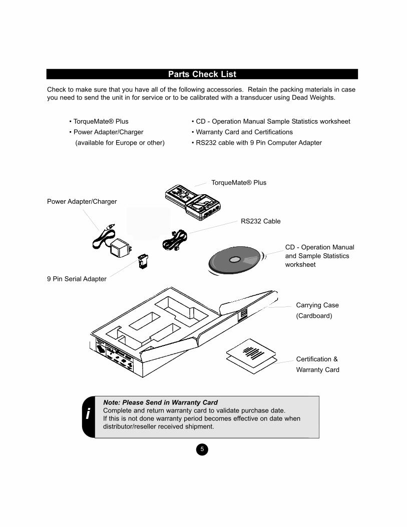
Parts Check List Check to make sure that you have all of the following accessories. Retain the packing materials in caseyou need to send the unit in for service or to be calibrated with a transducer using Dead Weights.
TorqueMate® Plus
Power Adapter/Charger
RS232 Cable
9 Pin Serial Adapter
CD - Operation Manualand Sample Statisticsworksheet
Certification & Warranty Card
Carrying Case(Cardboard)
• TorqueMate® Plus • Power Adapter/Charger
(available for Europe or other)
• CD - Operation Manual Sample Statistics worksheet• Warranty Card and Certifications • RS232 cable with 9 Pin Computer Adapter
iNote: Please Send in Warranty CardComplete and return warranty card to validate purchase date. If this is not done warranty period becomes effective on date whendistributor/reseller received shipment.
Features
6
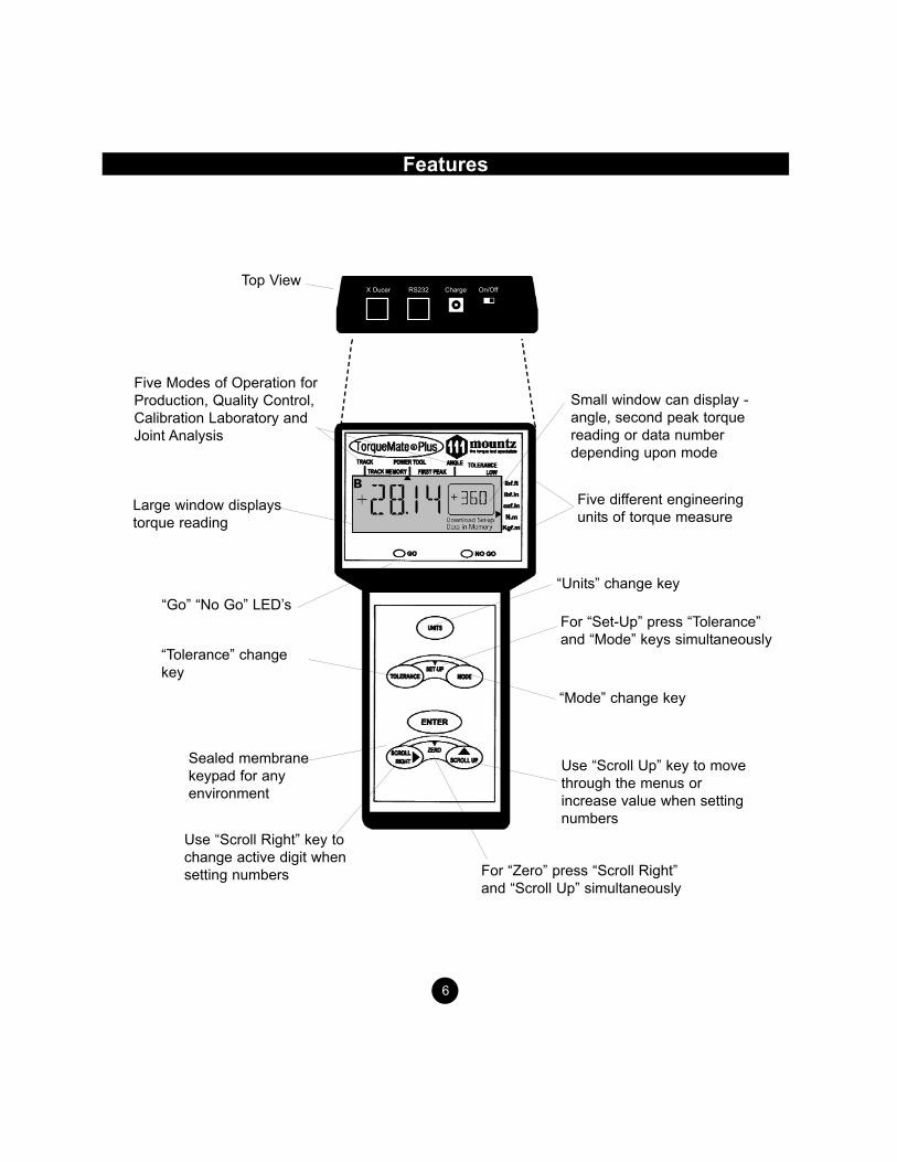
“Units” change key
For “Set-Up” press “Tolerance”and “Mode” keys simultaneously
Five different engineeringunits of torque measure
Small window can display -angle, second peak torque reading or data numberdepending upon mode
“Mode” change key
For “Zero” press “Scroll Right”and “Scroll Up” simultaneously
Sealed membranekeypad for anyenvironment
Use “Scroll Right” key tochange active digit whensetting numbers
Use “Scroll Up” key to movethrough the menus orincrease value when settingnumbers
“Tolerance” changekey
“Go” “No Go” LED’s
Large window displaystorque reading
Five Modes of Operation forProduction, Quality Control,Calibration Laboratory andJoint Analysis
Top ViewX Ducer RS232 Charge On/Off

Features (cont.)Output: RS-232C port for data transfer to printer, data logger or computer. Engineering Units: 5 different units of torque measure are available. lbf.ft., lbf.in., ozf.in., N.m., Kgf.m(Other measurement units available as special order) Battery Operated: NiMH batteries provide long life, without “memory”. Up to 8 hours of operation per charge. Low battery indicator turns on when battery is low. Automatically shuts downwhen battery is critically low.Memory: Stores up to 1000 torque and/or angle values. Simply press the Enter Key to store data inmemory. Up To 15 Transducers: Program & calibrate transducers for a variety of applications.High Impact Plastic Housing: Provides portable belt or bench mounting. Set (Go/No Go) Tolerance: Easily set user high and low limits for Torque and Angle with green and redGo/No Go LED’s and an audible buzzer. Auto Reset: Automatically resets the display when a new torque cycle is sensed (Peak & First Peakmode). Resets in 3 seconds (Power Tool Mode).Manual Display Reset: Data is held on the display until: 1. The Enter key is pressed clearing the display and storing the data in memory or 2. The Scroll Right key is pressed clearing the display withoutstoring the data in memory. Calibration: Fast Calibration allows the user to quickly enter and store the full scale mv/v and rangevalue of each transducer. True Calibration allows the user to apply torque with dead weights and captureand store 3 calibration points in each direction. Both calibration procedures are quick and user friendly.Filters: Three software selectable filters (3600Hz, 1500Hz, 500Hz) allow the user to filter out unwanted“noise”, minimizing non-torque spikes that can occur when testing pulse or power tools.
7

Before You Begin
Transducer NumberYou must have a calibrated transducer with a transducer number assigned to it. Always make sure theTorqueMate® Plus is set to the transducer number that you have attached. Every time you turn on theTorqueMate® Plus the current transducer number and its associated range will be displayed (depictedby “c-XX” where XX is the transducer number). Press Enter to confirm that the proper transducer isattached. If it is not the proper transducer number you must change it to the correct number or you will beusing incorrect calibration data. To change the number press the Scroll Right key once - this will activatethe Scroll keys. Now press the Scroll Up or Scroll Right keys until the proper transducer number is dis-played. Press Enter to select and go into the operation mode.
Battery ChargingThe TorqueMate® Plus must be turned "ON" in order to charge the battery.The microprocessor monitorsthe charging cycle of the NimH batteries and must be turned on to do so. The TorqueMate® Plus will gointo battery saving PAUSE mode after 5 minutes without use, but will still be charging. TheTorqueMate® Plus can be used when the batteries are low and the AC adapter is plugged in.
The TorqueMate® Plus has two smart charging modes: Trickle and Fast Charge. Charging theTorqueMate® Plus, without a transducer attached, activates the Trickle Mode. This mode charges thebattery, but there is not a specific time frame when charging will be completed. The Fast Charge Modeis activated when a transducer is plugged into the port.
Therefore, to achieve the most efficient charging, it is recommended that you charge your unit with atransducer plugged into the transducer port and the unit turned "ON" to obtain a full charge. See page22 for further detail on charging of the batteries.
Transducer SelectionTransducer selection is very important. Whenever possible, select a transducer range that is approxi-mately 2 times the range to be used or tested. If you are typically using the tester at 50 lbf.ft., select a100 lbf.ft. transducer. This significantly reduces the chance that you will overload and damage thetransducer.
Connecting and Disconnecting TransducersDo not connect or disconnect a transducer with the TorqueMate® Plus powered on. Connect the trans-ducer and then power on the TorqueMate® Plus and select the cell that you wish to use for the trans-ducer. When disconnecting the transducer, turn off the unit and then disconnect the transducer.
8
IMPORTANT!
iNote: When Programming TransducersThe torque range and the measurement units of the transducer arealso shown. The torque range will default to “3333” if a transducerhas never been assigned to the number displayed.

Operation
The TorqueMate® Plus is an accurate, user friendly torque display that allows a user to quickly changefunctions and features without getting “lost” in a menu structure. Any change made after pressing theenter key returns you directly to the operation mode.
CHANGING MODES AND UNITSWith the Scroll and Enter Keys - The most used functions are changed by simply pressing the keylabeled with the feature you want to modify. Change the value easily with the Scroll Up. Once you haveselected the new setting or feature simply press the Enter key to accept and return to operation with thenew setting. FOR EXAMPLE - to change the operation mode from Track to First Peak, press the Mode key(5) onceand then press the Scroll Up key(3) until the displayicon points to the First Peak mode(7). PressEnter(1) to accept and return to the operation modein the First Peak setting. The Mode icon will point toFirst Peak.
CHANGING NUMBERS With the Scroll and Enter Keys - To change numberssuch as the high and low tolerance, theTorqueMate® Plus is much like setting an alarmclock. The active digit (blinking) is changed with theScroll Up key, to move to the next digit, simply pressthe Scroll Right key (the next digit will now blink). Toset all the Digits in the same manner, press Enteragain and the number is set. FOR EXAMPLE - to set a tolerance when in peak or first peak mode, press the Tolerance key(4). The display will show the Low tolerance set point. The first digit will be flashing. Change the value ofthe flashing digit by pressing the Scroll Up key(3).Change to the next digit by pressing the Scroll Rightkey(6). When the value is reached press the Enterkey(1). To set the High tolerance value, follow thesame procedure as with setting Low tolerance. Press Enter(1) when the high value is set and you will be returned to the operation mode.
9
7
6
2 5
1
3
4
Operation (cont.)
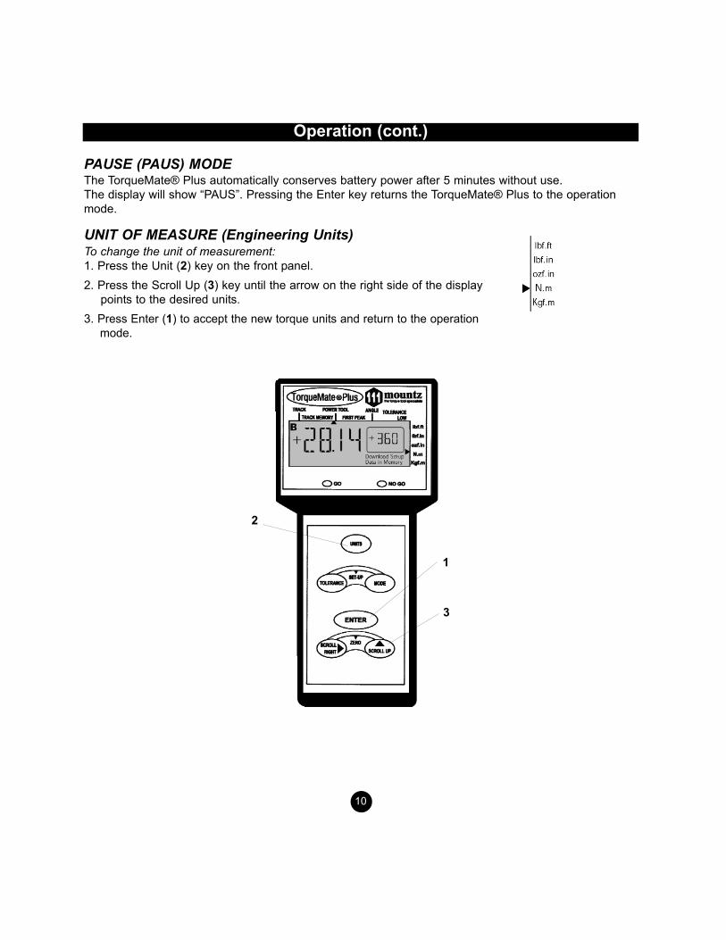
PAUSE (PAUS) MODE The TorqueMate® Plus automatically conserves battery power after 5 minutes without use. The display will show “PAUS”. Pressing the Enter key returns the TorqueMate® Plus to the operationmode.
UNIT OF MEASURE (Engineering Units)To change the unit of measurement:1. Press the Unit (2) key on the front panel. 2. Press the Scroll Up (3) key until the arrow on the right side of the display
points to the desired units. 3. Press Enter (1) to accept the new torque units and return to the operation
mode.
10
2
1
3

Operation (cont.)
11
MODE OF OPERATIONTo change the mode of operation: 1. Press the Mode key. 2. Press the Scroll Up key until the mode arrow points to the desired mode of operation:
a) Track Mode: The display “tracks” the applied torque in clockwise and counterclockwise directions.There is a real time torque feature that is available only in Track mode. This feature outputs read-ings to the RS232 port at a rate of 4 times per second. To enable this feature, press Tolerance andScroll Right Simultaneously. You see the Firmware Revision. Press Units. The unit goes back toreading screen and outputs torque reading at the rate of 4 times per second. Pressing the Enterkey will disable this feature.
b) Peak Mode: The display holds the highest peak torque applied.c) Power Tool Mode: Used for measuring torque with power tools such as nutrunners and impulse
tools. Always use a quality joint rate simulator (run down adapter) when testing power tools in asimulated application. If you do not use a joint rate simulator, damage to the transducer and or errat-ic readings might occur.
d) First Peak Mode: The display holds the first peak torqueapplied and disregards any further input. This function isprimarily used for testing and calibrating click type mechani-cal torque wrenches by hand (without a calibration loadingbench).
The TorqueMate® Plus captures the point the wrench clicks, and disregards any further input fromthe operator. Second peak, if any is shown in the window on the display.
e) Angle Mode: Combined with a transducer with angle encoder, the TorqueMate® Plus measuresthe angle of rotation of a fastener (with high and low angle tolerance) after a programmed thresh-old torque has been reached. This feature is used when an angle is specified rather than a finaltorque. Joint rate and breakaway torque can also be measured. (See application notes.)
3. Press the Enter key to accept the new mode of operation.
Examples of Mode ApplicationsTrack Mode: Use for reading, running or varying torque on motors and machinery. Use for calibratingDial type wrenches on a calibration loading bench.Peak Mode: Use for calibrating any hand type torque (dial, beam, screwdriver) wrench except handtesting of clicker type wrenches. Use Peak Mode with the Go/No Go feature. Not for use with powertools. Power Tool Mode: Use Power Tool Mode whenever testing dynamic tools such as nutrunners, electricscrewdrivers and impulse tools.First Peak Mode: Designed exclusively for manually calibrating clicker type torque wrenches (by hand).Reads the point at which the wrench “clicks” (first peak), and the point when the operator stopped apply-ing torque (second peak). Also good for operator training. Apply torque smoothly to avoid false first peakreadings.Angle Mode: Use Angle Mode to apply a specified angle to a fastener after reaching a threshold torque.Also used to verify break away torque of a fastener and to determine the joint rate of a fastener(see page 12 and applications notes for detailed information on Angle mode usage).
Operation (cont.)
SETTING GO AND NO/GO TOLERANCE (High/Low) LIMITSIn the Peak, Power Tool or First Peak mode: 1. Press the Tolerance key (the arrow icon will point to Low Tolerance). 2. Change the value of the flashing digit by pressing the Scroll Up key (and the decimal will be fixed). 3. Scroll to the next digit by pressing the Scroll Right key. 4. Press Enter to save the low limit and display the High Tolerance limit. 5. Repeat to set the High limit. Press Enter when finished. The TorqueMate® Plus will now activate the Green LED and buzzer when reaching a peak over the lowlimit, and will activate the Red LED and buzzer when going over the high limit.
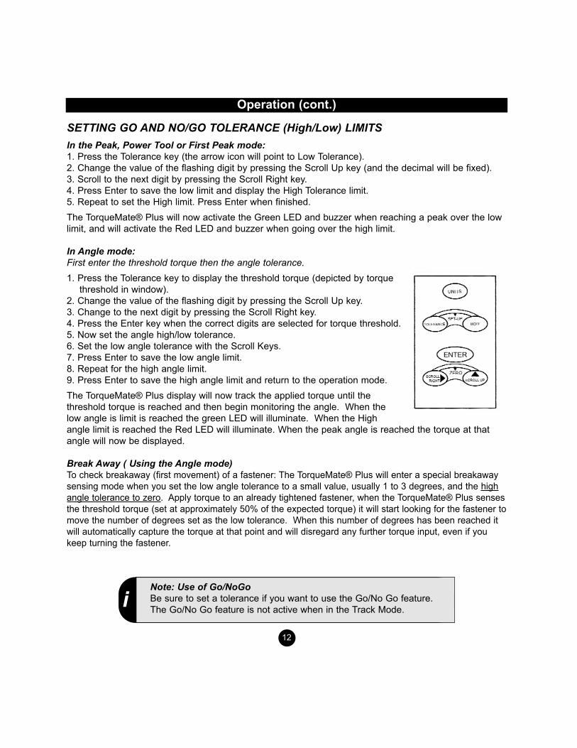
In Angle mode:First enter the threshold torque then the angle tolerance.1. Press the Tolerance key to display the threshold torque (depicted by torque
threshold in window). 2. Change the value of the flashing digit by pressing the Scroll Up key. 3. Change to the next digit by pressing the Scroll Right key. 4. Press the Enter key when the correct digits are selected for torque threshold. 5. Now set the angle high/low tolerance. 6. Set the low angle tolerance with the Scroll Keys. 7. Press Enter to save the low angle limit. 8. Repeat for the high angle limit. 9. Press Enter to save the high angle limit and return to the operation mode.The TorqueMate® Plus display will now track the applied torque until thethreshold torque is reached and then begin monitoring the angle. When thelow angle is limit is reached the green LED will illuminate. When the Highangle limit is reached the Red LED will illuminate. When the peak angle is reached the torque at thatangle will now be displayed.
Break Away ( Using the Angle mode)To check breakaway (first movement) of a fastener: The TorqueMate® Plus will enter a special breakawaysensing mode when you set the low angle tolerance to a small value, usually 1 to 3 degrees, and the highangle tolerance to zero. Apply torque to an already tightened fastener, when the TorqueMate® Plus sensesthe threshold torque (set at approximately 50% of the expected torque) it will start looking for the fastener tomove the number of degrees set as the low tolerance. When this number of degrees has been reached itwill automatically capture the torque at that point and will disregard any further torque input, even if youkeep turning the fastener.
12
iNote: Use of Go/NoGoBe sure to set a tolerance if you want to use the Go/No Go feature.The Go/No Go feature is not active when in the Track Mode.
13
iNote: Pressing The Wrong KeyIf at any time you press the wrong key, and you do not want tomake changes to the function you incorrectly selected simply pressthe Enter key to keep the current setting (you can also turn theTorqueMate® Plus off and on again). If you press the wrong keywhile calibrating turn the unit off then on again and start over (datais not saved until the final operation is entered).
Operation (cont.)
To check the joint rate:Check the rate of a joint (soft, medium or hard) by tightening the fastener to the specified torque and measuring the rotation angle of the fastener from 50% to 100% of the torque applied.• Set the threshold to 50% of expected torque.• Set the low angle tolerance to zero.• Set the high angle tolerance to a high value (over 900°).Testing of the Joint Rate: Determine if the application joint is a hard, medium or soft joint. This is determined by measuring theangle of rotation of the fastener from approximately 50% of the final torque to the final torque. If theangle is less than 30 degrees the joint is considered hard. If the angle is 30 to 360 degrees the angle isconsidered medium. If the angle is 360 degrees or more it is considered soft.A quick method to do this is to use the TorqueMate® Plus with a hand held transducer in Peak Mode.First tighten the application fastener to 50% of the required torque with the TorqueMate® Plus in peakmode. Now mark the head of the fastener so you can roughly determine the angle of further rotation.Once again place the TorqueMate® Plus wrench on the fastener and tighten to the final desired torque.Measure or approximate the angle of rotation. You do not need to know the exact angle, only the range.This angle of rotation should be simulated on the test fixture, with a joint rate simulator, when testingpulse tools (or any power tool). Clearing Numbers On The Display During Operation - When a reading is on the display, press theEnter key to clear the number and send it to memory and out the RS 232C port. If you want to clear thedisplay and bypass sending the data to memory press the Scroll Right key. If Auto Clear is set to ON and the TorqueMate® Plus is in Peak or First Peak mode, the unit will auto-matically clear itself upon sensing additional torque saving you the step of having to press the ScrollRight key. If you want to save the data on the display in memory, press the Enter Key before you applya new torque value or the unit will automatically clear the display and you will lose the data.
When in power tool mode, and Auto Clear is ON, the display automatically clears in 3 seconds. So youmust press the Enter key within three seconds to save the data to memory.If this is not enough time, set Manual Clear to ON and press the Enter key to clear the display and sendthe data to memory, or the Scroll Right key to clear the display and bypass sending the data to memory.When the memory is full, pressing the Enter key will not clear the display. A beep sound and the No Goindicator will flash warning the user that no more readings can be accepted into memory. See the CLRfunction (Item 3, under Set-Up) for the procedure to clear the data in memory.

Set-Up Mode
Enter the Set-Up mode by pressing the Tolerance and Mode key simultaneously (the Set-Up iconwill turn on). Scroll through the various Set-Up functions by pressing the Scroll Up key. When you getto the option you want to change press the Enter key. Upon changing any option, you will be returnedto the operation mode.
The following seven paragraphs (DISP, DOWNLOAD, CLR, MANUAL/AUTO CLEAR, TRANSDUCERCODE, CAL, FIL) is the sequence of functions in the Set-Up menu:
1. DISP - DATA IN MEMORY(Display The Values Stored In Memory) DISP and the Data in Memory icon will be shown. a. Press Enter to select this option. b. The number of data in memory will be displayed on the large digits.c. Press the Scroll Right key to view the last data in memory. Press Scroll Up to read the next higher
data number. If the data number has both Torque and Angle associated with it then the TorqueMate®Plus will first display the torque value and then the Angle (as shown by the Torque or Angle Icon inthe Window).
c. Press the Scroll Right key to read the next lower data number (i.e., 100, 99...98). The Scroll Up keywill not scroll from the last data number to the first (i.e., 100 to 1).
d. Press Enter to exit and return to normal operation.
2. DOWNLOAD DATA IN MEMORY(Downloads Data In Memory To A Computer or Printer)Make sure an RS232 cable is attached and press the Enter key to downloaddata to a computer. The data number will count down on the torque windowas the values are downloaded to a dot matrix printer or computer. Press the Enter key at any time to stop the transfer of data. Data is sent in the following stream: Data #, Torque, Units, Angle. The protocol is 8, 1, n at 4800bps.
3. CLR - DATA IN MEMORY(Clears the data In memory) a. Press the Enter Key to select the Clear Memory (Clr) option
(Clr flashes on the LCD and the Data in Memory icon is shown). b. Press the Scroll Right key and the Scroll Up key simultaneously to
clear the memory. Press the Enter key to avoid clearing memory, and return to the operation mode. Note: when the memory is full, pressing the Enter key will not clear the display. A beep sound andthe No Go indicator will flash warning the user that no more readings can be accepted into memory.
14

Set-Up Mode (cont.)
4. MANUAL CLEAR/AUTO CLEAR (Selects The Reset (Clear) Mode For The Display)a. Press Enter to select this option. b. Press the Scroll Up key to toggle between Manual Clear ON or
Auto Clear ON. If the mode is set to Peak or First Peak mode the operation, for Auto Clear, is as follows:
If you turn ON Auto Clear Mode, the display will indicate On x, where x can be 1, 2, 3, 4, 5, 6, 7, 8, 9, or A. A numeric display indicates the time to clear after a peak is reached. For example, On 3 means that the display will clear 3 seconds after reaching a peak value. On A indicates that the display will automatically clear when the TorqueMate® Plus senses that you have applied additional torque after a peak is reached.
If the mode is set to Power Tool mode the operation, for Auto Clear, is as follows:If you turn ON Auto Clear Mode, the display will indicate On x, where x can be 1, 2, 3, 4, 5, 6, 7, 8, or 9. The numeric value indicates the time to clear after a peak is reached. For example, On 1 means that the display will clear 1 second after reaching a peak value.
Note: The time for Auto Clear during Power Tool mode is independent of the timer for Peak or FirstPeak.If in Auto Clear Mode:c. Press Scroll Up to scroll through the available selections for timing on Auto Clear.d. Press Enter to save and exit.
5. MEMORY ON/OFF(Turns on/off the send to memory and RS232 output when in Auto Clear mode).The Memory On icon will display. a. Press Enter to select this option.b. Press the Scroll Up key to toggle between Memory On or Memory OFF.c. Press Enter to save and exit.
With memory turned On and Auto Clear turned on the display will clear after the Auto Clear timer expiresand the value on the display will be sent to memory as well as out the RS232 port. Note that with thesefunctions selected the memory of the TorqueMate® Plus may fill rapidly. Note that, when the memory isfull, pressing the Enter key will not clear the display. A beep sound and the No Go indicator will flashwarning the user that no more readings can be accepted into memory. See the CLR function (Item 3)above for the procedure to clear the data in memory.
15
Set-Up Mode (cont.)
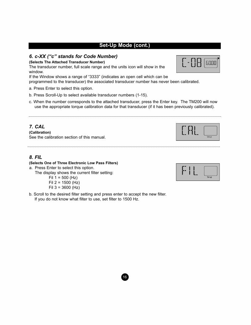
6. c-XX (“c” stands for Code Number)(Selects The Attached Transducer Number)The transducer number, full scale range and the units icon will show in thewindow. If the Window shows a range of “3333” (indicates an open cell which can be programmed to the transducer) the associated transducer number has never been calibrated. a. Press Enter to select this option. b. Press Scroll-Up to select available transducer numbers (1-15). c. When the number corresponds to the attached transducer, press the Enter key. The TM200 will now
use the appropriate torque calibration data for that transducer (if it has been previously calibrated).
7. CAL(Calibration) See the calibration section of this manual.
8. FIL(Selects One of Three Electronic Low Pass Filters) a. Press Enter to select this option.
The display shows the current filter setting: Fil 1 = 500 (Hz) Fil 2 = 1500 (Hz) Fil 3 = 3600 (Hz)
b. Scroll to the desired filter setting and press enter to accept the new filter. If you do not know what filter to use, set filter to 1500 Hz.
16
Set-Up Mode (Fast Cal)
Quickly Entering Calibration Data For A Transducer (Fast Cal)To quickly enter calibration data for a transducer you must know the mv/v signal output at full scaleand the range of the transducer (both should be marked on the transducer). If the transducer is not marked with this information then contact manufacturer of the transducer to obtain it.
If the transducer is a Brush-Less transducer it is marked as 5 V output rather than a mV/V output.Please note that this type of transducer must be calibrated using a True, deadweight calibration.
Turn the TorqueMate® Plus on and press Enter when it shows the current cell number. 1. Enter Set-up by pressing the Mode and Tolerance key simultaneously. 2. Press the Scroll Up key until the display shows “CAL”. 3. Press the Enter key. Now press the sequence: Enter, Scroll Right, Tolerance.4. Select the proper units with the Scroll Up key then press the Enter key. 5. Select the cell number for the transducer to be calibrated (1-15) with the Scroll Up key, then press
Enter.6. Enter the full scale range of the new transducer (default is 3333). Use the Scroll Up key to change
the digit value, the Scroll Right key to select a different digit. Do not worry if the decimal is wrong,you will change that next. Press Enter when the numbers are correct.
7. Now set the decimal place with the Scroll Right key. Press Enter to save the decimal place.
8. Now enter the mv/v range of the transducer at full scale (default 2.000). Use the Scroll Up and theScroll Right key as you did with the range (you cannot change the decimal place). Press Enter whenfinished.Note: The TorqueMate® Plus will always display 2.000, even if you have previously programmed a dif-ferent value.
9. The display will now show Fast (FAST) Cal. Press Enter. 10. The transducer is now coded and calibrated using mv/v and range. The calibration data will be writ-
ten to memory. Whenever you select the corresponding code number the TorqueMate® Plus will usethe calibration data that was saved.
17
iNote: Calibration SecurityTo ensure that inadvertent alteration of calibration data does not occur a KeySequence Override is required to be entered at the CAL prompt. After hitting Enterto activate the Cal Menu the Key Sequence Override is accomplished by pressingEnter, Scroll Right & Tolerance. Press these keys in exact order to access the CALmenu.
iNote: Setting Decimal Place Always enter the range value starting with the first decimal place. For example 10 ft.lb. transducer should be programmed to 10.00 not 010.0 or 0010.
Transducers
The TorqueMate® Plus can be used with 1 to 4 mv/v transducers. Simply assign a code number to thetransducer (1-15) and calibrate it with dead weights (True Cal), or enter the known mv/v at full scaleand the range (Fast Cal). The TorqueMate® Plus will store the calibration data in memory for that trans-ducer under the code number you assigned.
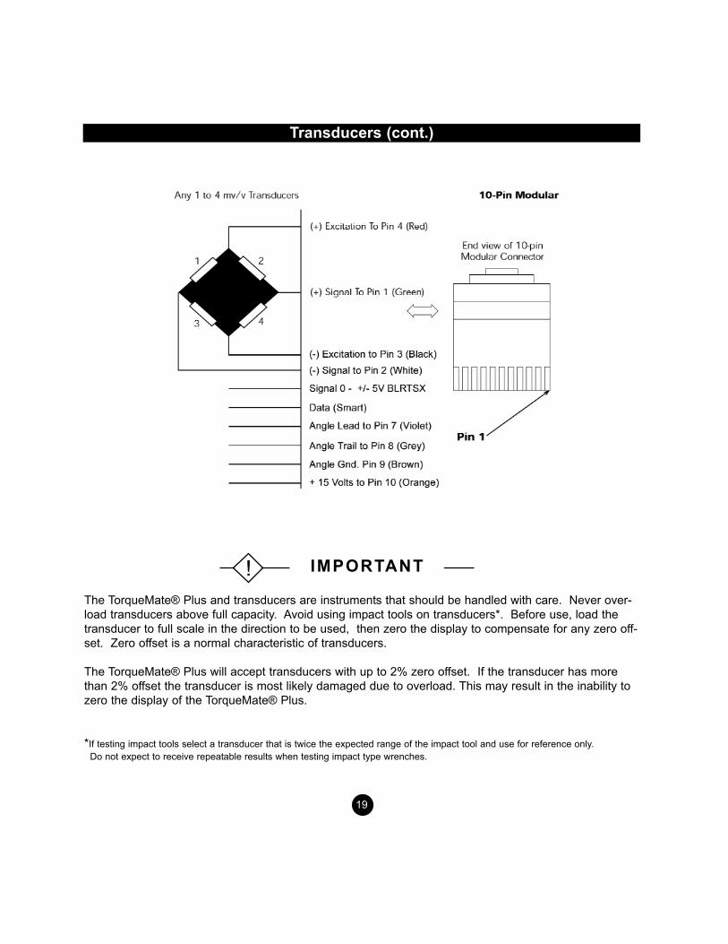
SELECTING TRANSDUCER CABLESA cable with a 10 pin modular plug, which goes into the TorqueMate® Plus, and bare wires on the otherend is not included with the TorqueMate® Plus. This cable is available, upon request, at additional cost.The part number is 065145. The correct part number for an RTSXA (with Angle and 10 pin Bendix) is065151.
If you have a transducer that has a special connector Mountz can make a custom connector for theTorqueMate® Plus. For example, if your transducer has a Bendix type connector you can order a cablewith the TorqueMate® Plus 10 pin connector on one end and a Bendix connector on the other. (See listof cables below)
Calibration NotesWhen using the Fast Cal option on the TorqueMate® Plus, the TorqueMate® Plus will take the mv/ventry that you manually programmed during transducer calibration, and adjust the gain and span auto-matically. For example, if the transducer has a mv/v signal of 2.010 at a full range of 50 lbf.ft. then theTorqueMate® Plus will assume when it senses 2.010 mv/v of output from the transducer that a torque of50 lbf.ft. is being applied (the display will show 50 lbf.ft.).
When using the True Cal option, the TorqueMate® Plus will take an actual reading of the output of thetransducer when certified dead weights are applied.
Configuration Part NumberConnections to the TorqueMate® Plus1. RTSX to TorqueMate® Plus (6 pin Bendix) 0651382. BTSX to TorqueMate® Plus (4 pin Bendix) 0651233. TorqueMate® Plus connector/no connector 065145
(to connect to other transducers)4. RTSXA (with Angle indication and 10 pin Bendix) 0651515. BLRTSX (with Brushless indication and 10 pin Bendix) 065134
18
IMPORTANT!
The TorqueMate® Plus and transducers are instruments that should be handled with care. Never over-load transducers above full capacity. Avoid using impact tools on transducers*. Before use, load thetransducer to full scale in the direction to be used, then zero the display to compensate for any zero off-set. Zero offset is a normal characteristic of transducers.
The TorqueMate® Plus will accept transducers with up to 2% zero offset. If the transducer has morethan 2% offset the transducer is most likely damaged due to overload. This may result in the inability tozero the display of the TorqueMate® Plus.
*If testing impact tools select a transducer that is twice the expected range of the impact tool and use for reference only. Do not expect to receive repeatable results when testing impact type wrenches.
19
Transducers (cont.)
IMPORTANT!
Transducer Calibration
• Always calibrate the TorqueMate® Plus with the unit plugged into the AC power adapter and makesure the batteries are fully charged.
• Calibration data for up to 15 transducers can be memorized by the TorqueMate® Plus.
There are two options available for calibrating a transducer: 1. FAST - Fast Cal means that you do not use dead weights for calibration. The TorqueMate® Plus will
assume the mv/v signal entered is accurate and automatically span the range of the transducer andstore it in memory.
2. TRUE - True Cal means that you use calibration arms and dead weights to calibrate the transducer.The TorqueMate® Plus will take three readings in each direction and create a calibration table inmemory.
Procedure for CalibrationAttach the transducer to be calibrated. • Enter Set-up by pressing the Mode and Tolerance keys at the same time. The Set-up icon will show
and the display will be blank. • Press the Scroll Up key until the LCD shows CAL. • Press Enter to select this option.
• The Units icon will be flashing. • Press the Scroll Up key to select the units that you will be calibrating this transducer to. Press Enter to
select the Units. • The display will now show the expected transducer number (c-1 to c-15). Press the Scroll Up key
until the desired transducer number is displayed. If the TorqueMate® Plus transducer number hasnever been used it will show “3333” for the range (default). This will change as soon as you assign arange to the transducer. Press Enter to select the proper transducer number.
• Enter the range of the transducer to be calibrated. Press the Scroll Up key to change the value of theflashing digit. Press the Scroll Right key to select a different digit. When the desired value has beenselected press Enter to accept. Now set the decimal by pressing the Scroll Right key. Press theEnter key to save the range of the transducer.
Continue the calibration with the steps on page 21.
20
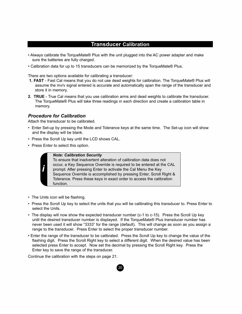
Note: Calibration SecurityTo ensure that inadvertent alteration of calibration data does notoccur, a Key Sequence Override is required to be entered at the CALprompt. After pressing Enter to activate the Cal Menu the KeySequence Override is accomplished by pressing Enter, Scroll Right &Tolerance. Press these keys in exact order to access the calibrationfunction.
i
Transducer Calibration (cont.)
The display will now show the mv/v signal of the transducer at full range. The default is 2.000 and themV/V range can be anywhere between 1.000 and 4.000 mV/V. Enter the actual value by pressing theScroll up key to change the value of the blinking digit. Press the Scroll Right key to select a differentdigit. When the value is correct, press the Enter key.
Brushless Transducer:The first digit may also be changed to 5 and 5.000 is the only permitted value. Only set the first digit to 5if you are calibrating a Brushless transducer (BLRTSX type). These BLRTSX transducers output 5 V atfull range.
After entering the mv/v signal the display will show “FAST CAL”. If you do not want to use dead weightspress Enter and the TorqueMate® Plus will use the mv/v signal you entered as the full scale span signalof the transducer.
If you are going to use dead weights press the Scroll Up key to show “TRUE CAL”. Press Enter toselect TRUE CAL.
After selecting TRUE CAL, the display will show “- P0”. This means that the tester is “waiting” for you toenter Point Zero in the negative (counterclockwise) direction (also referred to as the negative zero offsetof the transducer).
Exercise the transducer three times to full scale in the CCW direction and wait 30 seconds with no loadfor the transducer to stabilize. Press the Scroll Right key (not the Enter key) to accept the negative zeropoint (offset).
The TorqueMate® Plus will now show “- P1”. This means that it is waiting for the input for the first pointin the CCW direction, always 10% of the full scale range of the transducer. Place the appropriateweights on the calibration arm and let the weight stabilize.
21
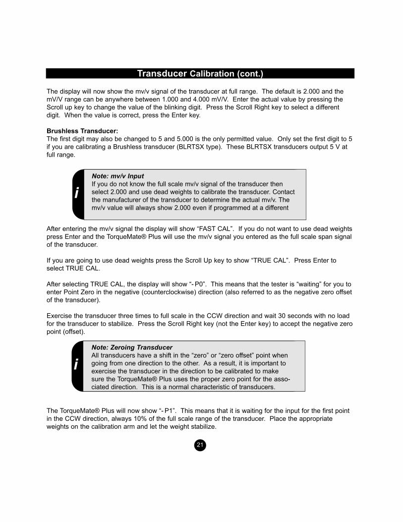
Note: mv/v InputIf you do not know the full scale mv/v signal of the transducer thenselect 2.000 and use dead weights to calibrate the transducer. Contactthe manufacturer of the transducer to determine the actual mv/v. Themv/v value will always show 2.000 even if programmed at a different
i
iNote: Zeroing TransducerAll transducers have a shift in the “zero” or “zero offset” point whengoing from one direction to the other. As a result, it is important toexercise the transducer in the direction to be calibrated to makesure the TorqueMate® Plus uses the proper zero point for the asso-ciated direction. This is a normal characteristic of transducers.

Transducer Calibration (cont.)
Press the Enter key to display the readings for “- P1”. The display will now show what the TorqueMate®Plus “thinks” is point one in the CCW direction. Use the Scroll Up (increase) and Scroll Right(Decrease) keys to make the TorqueMate® Plus read the torque applied with the weights. Press theEnter key when the value is correct. Make sure the weights are not swinging, otherwise you will haveunstable readings.
The TorqueMate® Plus will now show “- P2” which means it is time to input point 2 in the CCW directionas you did with point one. Point 2 should always be 50% of the full scale range of the transducer.Press Enter and place the appropriate weights for point two. Make theTorqueMate® Plus read what is correct for - P2 by pressing the Scrollkeys. When the TorqueMate® Plus reads the proper torque for pointtwo in the CCW direction press Enter and repeat for point three (alwaysthe full scale value since it is the last point in that direction).
After entering the third point in the CCW direction, the display will show “+P0”. This means that theTorqueMate® Plus is waiting for you to enter the zero point in the clockwise direction (offset). Exercisethe trans-ducer to full scale in the clockwise direction three times and let the transducer stabilize with noload for 30 seconds. Press the Scroll Right key to accept the clockwise Zero point. Proceed in theclockwise direction as you did in the Counterclockwise direction for points “+P1”, “+P2” and “+P3”.
After pressing Enter for the third point in the clockwise direction (+P3), before you remove the weights,the TorqueMate® Plus will go directly into the operation mode and should display the full scale torque inthe clockwise direction. Remove the weights and make sure you have labeled the transducer with theproper transducer code number for future reference.
If you are going to check the accuracy of the calibration. Place unit in track mode and remove allweights, exercise the transducer three times in the direction you are going to check and press the ScrollRight and Scroll Up keys to automatically adjust the zero (offset). Apply the weights in increasing orderand check for accuracy. Repeat for all transducers to be calibrated.
Calibration intervals are dependent on the amount that a transducer is used. We recommend that youcheck the transducer every month at first. If the calibration is within specs after the first few months,increase the interval to 3 months. If you still find that the unit is in calibration increase the interval to 6months.
22
iNote: Calibration IntervalsMountz Service Centers will calibrate and certify any transducer ortransducer / display to N.I.S.T. It is recommended that this happenevery 6 months but calibration intervals should be based on usage.

Charging the Batteries
Always leave the TorqueMate® Plus turned on when charging the batteries. This allows the micro-processor to monitor the charging cycle. The TorqueMate® Plus can be used while charging withoutaffecting torque accuracy. The unit will go into battery saving pause (PAUS) mode after 5 minutes with-out use, but the batteries will still be charging.
• The microprocessor monitors the charging process of the batteries. Always keep the TorqueMate®Plus turned on when charging batteries (the TorqueMate® Plus will continue to charge batteries whilein Paus Mode).
• The TorqueMate® Plus can be used while charging batteries.
• If the batteries are fully discharged, the TorqueMate® Plus may take a few minutes to power up afterbeing plugged into the AC adapter.
BATTERY STRENGTHThe TorqueMate® Plus battery pack should last up to 10 hours with normal use and maximum charge.When the battery charge falls below a certain voltage the “B” icon will show on the display. At this pointyou should plug the unit into the AC adapter or replace the battery pack with a freshly charged pack. Ifthe battery pack falls below a level that will effect accuracy it will automatically turn off.
CHARGING TIME4 Hours Minimum
BATTERY CHARGER 115 volt to 12 Volt DC, 300 mAg, Center Pin Positive
Other Adapters available upon request.
BATTERY CHARGING KITAccessory item that can be purchased.
Includes a charger and two batteries. Part Number: 771147
23

Application Notes
IMPULSE AND POWER TOOL TESTING
Impulse tools have become prevalent throughout industry. The advantages of ergonomics and function-ality of impulse tools are well known. It is also well known that, due to the lack of standards in theindustry, all impulse tools are not created equal.
The frequency at which the pulse tool pulses has not been standardized. Some are fast and some arerelatively slow. Some tools create sharp torque vs. time peaks and some create flat peaks. In additionto this, the characteristics of the joint (soft, medium or hard) changes the output of the tool, so a tool thatpulses one way on one type of joint will pulse differently on the next. To further complicate things, eachbrand of tool will act different given the same joint characteristics. And to make things worse, variationsin air pressure to the tool will also make the tool behave differently. The good news is that individualimpulse tools repeat under the same conditions (within reasonable limits). So creating the same condi-tions as the application under test is important.
Due to these non tester related variations, it is difficult, if not impossible, to create a torque tester thatwill be out-of-the-box accurate for all impulse tools and all joint conditions. This is not to say that thetester is not accurate, only that the conditions during test may not simulate the conditions during theapplication, and due to the variance in pulse tools, the tester may show a different torque value thanwhat is actually happening at the application.
In order to minimize the effects of these variances, the application must be analyzed so it can besimulated properly on the torque tester with a joint simulator.
The TorqueMate® Plus, and the mountz family of transducers have been designed to minimize thesevariations and are well suited for both the analysis of the application joint and the testing of theimpulse tool.
Always use a quality joint rate simulator (run down adapter) when testing power tools in a simulatedapplication. Do not use the peak mode. The power tool mode is designed to meet the demanding fre-quency requirements for testing dynamic torque applications.
24
IMPORTANT!
Application Notes (cont.)
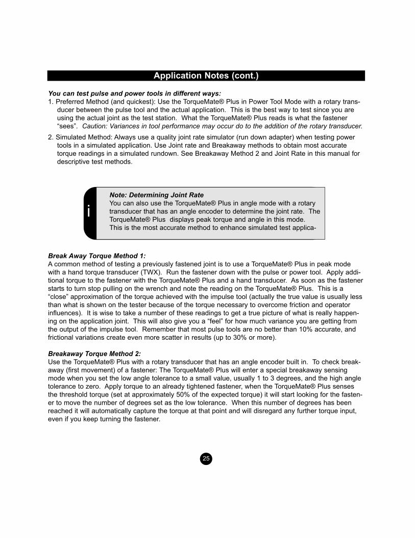
You can test pulse and power tools in different ways: 1. Preferred Method (and quickest): Use the TorqueMate® Plus in Power Tool Mode with a rotary trans-
ducer between the pulse tool and the actual application. This is the best way to test since you areusing the actual joint as the test station. What the TorqueMate® Plus reads is what the fastener“sees”. Caution: Variances in tool performance may occur do to the addition of the rotary transducer.
2. Simulated Method: Always use a quality joint rate simulator (run down adapter) when testing powertools in a simulated application. Use Joint rate and Breakaway methods to obtain most accuratetorque readings in a simulated rundown. See Breakaway Method 2 and Joint Rate in this manual fordescriptive test methods.
Break Away Torque Method 1: A common method of testing a previously fastened joint is to use a TorqueMate® Plus in peak modewith a hand torque transducer (TWX). Run the fastener down with the pulse or power tool. Apply addi-tional torque to the fastener with the TorqueMate® Plus and a hand transducer. As soon as the fastenerstarts to turn stop pulling on the wrench and note the reading on the TorqueMate® Plus. This is a“close” approximation of the torque achieved with the impulse tool (actually the true value is usually lessthan what is shown on the tester because of the torque necessary to overcome friction and operatorinfluences). It is wise to take a number of these readings to get a true picture of what is really happen-ing on the application joint. This will also give you a “feel” for how much variance you are getting fromthe output of the impulse tool. Remember that most pulse tools are no better than 10% accurate, andfrictional variations create even more scatter in results (up to 30% or more).
Breakaway Torque Method 2:Use the TorqueMate® Plus with a rotary transducer that has an angle encoder built in. To check break-away (first movement) of a fastener: The TorqueMate® Plus will enter a special breakaway sensingmode when you set the low angle tolerance to a small value, usually 1 to 3 degrees, and the high angletolerance to zero. Apply torque to an already tightened fastener, when the TorqueMate® Plus sensesthe threshold torque (set at approximately 50% of the expected torque) it will start looking for the fasten-er to move the number of degrees set as the low tolerance. When this number of degrees has beenreached it will automatically capture the torque at that point and will disregard any further torque input,even if you keep turning the fastener.
25
iNote: Determining Joint RateYou can also use the TorqueMate® Plus in angle mode with a rotarytransducer that has an angle encoder to determine the joint rate. TheTorqueMate® Plus displays peak torque and angle in this mode.This is the most accurate method to enhance simulated test applica-
Application Notes (cont.)
CALIBRATING TORQUE WRENCHESTo calibrate torque wrenches, use the TorqueMate® Plus with a bench mounted transducer or mount aTWX or SMX transducer in a fixture. Mount the transducer directly to a bench and apply the torquedirectly to the wrench by hand, or attach the transducer to a Mountz mechanical loader and isolate thewrench from the operator, reducing the possibility of operator errors (highly recommended). For manual calibration of click type wrenches use the First Peak mode on the TorqueMate® Plus so thetester will display the point at which the wrench “clicked” (First Peak) and the point when the operatorstopped pulling (Second Peak shown in the torque window). In First Peak Mode the TorqueMate® Pluswill disregard any further input once the wrench has clicked. Make sure you apply the torque slowly andsmoothly (try not to shake or you may induce a false first peak). To avoid this problem, calibrate clickwrenches in Peak mode on a mechanical loader.For dial type, screwdrivers and cam over torque wrenches put the TorqueMate® Plus in Peak mode. You can also enter the wrench accuracy tolerance in the TorqueMate® Plus’s Tolerance settings makingit easier to determine a Go or No/Go condition.
SENDING DATATo a ComputerWhen sending data to a computer file, use Windows 95 Hyperterminal or any serial communications software. Set the protocol in your software to 8,1,N 4800 (see your communication software manual).There are two ways to send data:1. Send all memorized data in memory from set-up mode.2. Send realtime data, one at a time, when in peak or power tool mode and press the enter key.
Capture data from the TorqueMate® Plus using Hyperterminal in Windows 95 or NT
1. Select "Start", "Programs", "Accessories", and then "Hyperterminal". Then select HyperTerminal.2. When the program starts you will be asked to choose an icon and assign a name. Choose any icon you prefer and choose a name such as "Data_Aq", for example. Click OK.3. The "Connect To" screen will appear. This should be direct to a COM port. Just click OK, or if youwant to change the COM port, select the appropriate COM port and click OK.4. The "COM2 Properties" screen will appear. Choose 4800 Bits per second. Leave the default valuesfor character format (8 Data Bits, Parity - None, and Stop Bits 1). Change the Flow Control to "None".Click OK.5. Click "File" on the Menu Bar and select "Properties". When the "Data_Aq Properties" screen appearschoose the "Settings" tab and then choose "ASCII setup". In "ASCII receiving" check the box "Appendline feeds to incoming line ends". Click OK then OK again.6. Hyperterminal is now configured to allow data downloaded from the TM200 to be displayed to thescreen. If you want to capture data to a file as it is displayed then you must enable file capture. To cap-ture to a file, select "Transfer" from the Menu Bar and select "Capture Text". Then enter the folder andfile you wish to capture to.
Real Time Data to a Dot Matrix PrinterThe output of the TorqueMate® Plus when in all modes (except track) and while downloading from set-up can be sent directly to a serial dot matrix printer instead of a computer.
26

Filters
The process of converting pulse type dynamic mechanical torque to an electronic signal using a trans-ducer may result in unwanted inputs (noise), resulting in a distorted torque value (usually high). Often itis possible through the use of appropriate circuitry to selectively filter out some or all of the unwantednoise. Filtering is the process of attenuating unwanted components of a torque measurement (thosewhich are not torque related, noise) while permitting the desired torque measurement to pass.In general, if a joint is very hard, i.e., two pieces of steel with no washer, the tool may create sharpspikes that may create a great deal of electronic noise and “ringing”. Noise and ringing, in this case, aredefined as readings from the transducer that did not result in torque to the fastener (obviously we donot want to read this on the display). If the joint is very soft (two pieces of plastic with a crush washer)the tool might create more “rounded” or flat peaks as a result of the energy absorption characteristics ofthe soft joint, possibly resulting in much less noise. These two situations may create the need for differ-ent filters within the tester. A filter acts much like a sieve, it lets certain signals through and stops others.When you select different filters on the TorqueMate® Plus, you are selecting different “low pass fil-ters”. This means that the filter will “cut-off” or attenuate any signals above the cut off frequency of thefilter and “let pass” signals below. So a 500Hz filter theoretically will cut out any signal that is enteringthat is over 500Hz. If the power tool you are using inputs torque at a rate above 500Hz you might cutoff the peak and get a reading that is too low. When you are using a hand wrench, the rate of applica-tion is slow, so a 500Hz should work fine. To be safe, you should first try using the 3600Hz filter withpower tools. This will let most of the signal pass through. If you find that your readings are consistently high, or you get occasional peaks that are high, comparedto the real application torque (see testing of joint) you may be reading noise. Try using the 1500 Hzfilter. No single filter can be specified for every application. This is somewhat of a trial and errorprocess, however experience has shown that 1500 Hz is the filter selection that should work the thebest for most power tool applications.
27
Accessories
28
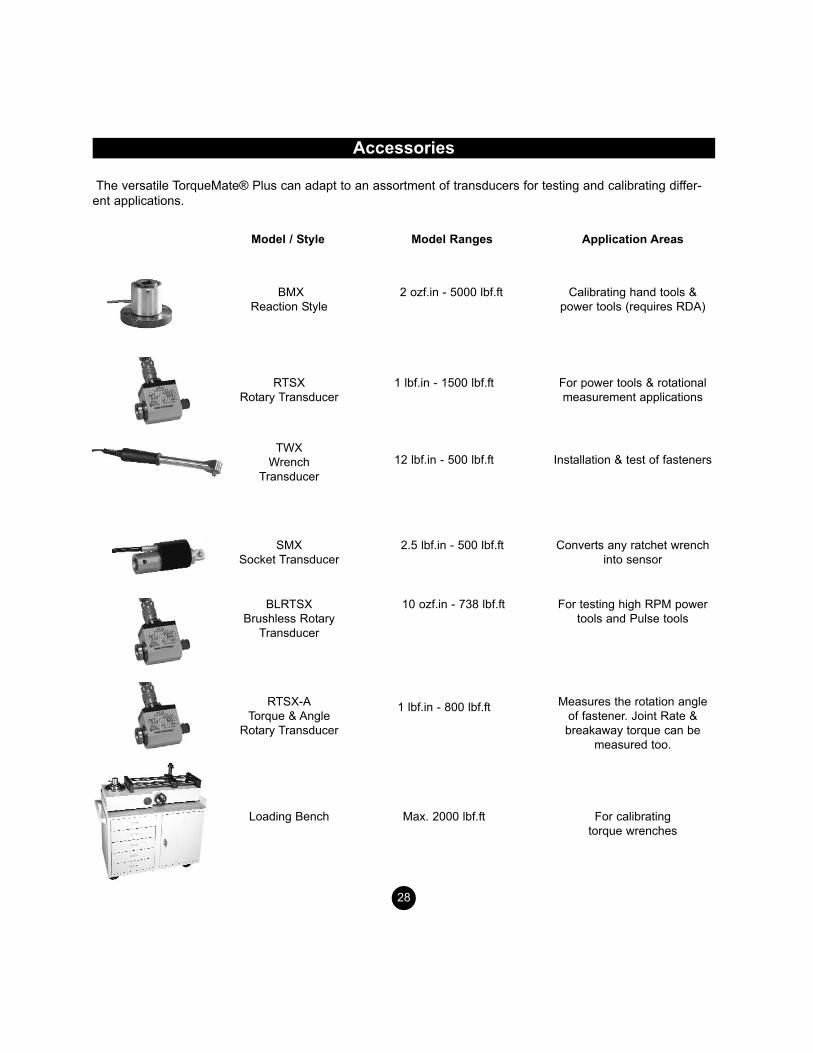
The versatile TorqueMate® Plus can adapt to an assortment of transducers for testing and calibrating differ-ent applications.
BMXReaction Style
RTSXRotary Transducer
TWXWrench
Transducer
SMXSocket Transducer
Model / Style Model Ranges
2 ozf.in - 5000 lbf.ft
1 lbf.in - 1500 lbf.ft
12 lbf.in - 500 lbf.ft
2.5 lbf.in - 500 lbf.ft
Application Areas
Calibrating hand tools &power tools (requires RDA)
For power tools & rotationalmeasurement applications
Installation & test of fasteners
Converts any ratchet wrenchinto sensor
BLRTSXBrushless Rotary
Transducer
10 ozf.in - 738 lbf.ft For testing high RPM powertools and Pulse tools
RTSX-ATorque & Angle
Rotary Transducer
1 lbf.in - 800 lbf.ft Measures the rotation angleof fastener. Joint Rate &breakaway torque can be
measured too.
Loading Bench Max. 2000 lbf.ft For calibrating torque wrenches

Accessories (cont.)
Battery Pack
NiMH 8.4 V 1.1Ah Part Number: 771170
Battery Charger
Input: 115 VAC60 HZ Output:12 VDC 300 mAPart Number: 771044
Adapter
D-Sub 9 pin to 6 Pin RJ12 (TorqueMate® Plus) Part Number: 701031
Transducer Cable
10 Pin Modular Plug to Open Wire Part Number: 065145
RS232 Cable
6 Pin to 6 Pin Modular Part Number: 065150
Battery Charging Kit
Includes a charger and two batteries Part Number: 771147
29

Specifications
Input Signal . . . . . . . . . . . . . . . . . . . . . . . . . . . . . . . . . . . .1 to 4 mV/V Full Scale
and 5 VDC Full Scale for Brushless Rotary (BLRTSX Type)
Bridge Excitation . . . . . . . . . . . . . . . . . . . . . . . . . . . . . . . . . . . . . . . . . . . .12 Volts
Software Selectable Filters . . . . . . . . . . . . . . . . . . . . . . .3600Hz, 1500Hz, 500Hz (Other Filter Values Programmed Upon Request)
Calibration . . . . . . . . . . . . . . . . . . . . . . . .Dead Weights (true) or Programmable (fast) (mv/v and range)
Display . . . . . . . . . . . . . . . . . . . . . . . . . . . . . . . .Large 4 digit LCD with additional 4 digit window.
Memory Capacity . . . . . . . . . . . . . . . . . . . . . . . . . . . . . . . . .Up to 1000 Readings
Communications . . . . . . . . . . . . . . . . . . . . . . . . . . . . .RS232C, 8,1,n, 4800 BPS
Power . . . . . . . . . . . . . . . . . . . . . . . . . . . . . . . . . . . . . . . . . . . . .NimH for long life
Clockwise andCounter- clockwise operation . . . . . . . . . . . . . . . . .Automatic, no switch required
Full accuracy in both directions.
Printout . . . . . . . . . . . . . . . . . . . . . . . . . . . . . . . . . . .Data #, Torque, Units, Angle
Angle Input . . . . . . . . . . . . . . . . . . . . . . . . . . . .Quadrature, 360 Counts per Rev.
Angle Resolution . . . . . . . . . . . . . . . . . . . . . . . . . . . . . . . . . . . . . . . . . . .1 Degree
Maximum Angle Count . . . . . . . . . . . . . . . . . . . . . . . . . . . . . . . . . . . . . . . . .9,999
Battery Life . . . . . . . . . . . . . . . . . . . . . . . . . . . . . . . . . . . . . . . . . .Up to 10 Hours
Accuracy . . . . . . . . . . . . . . . . . . . . . . . . . . . . . . . . . . . . . . .+/- .25% of full scale
30