Torque Sensor Attachment for the Da Vinci Surgical System...
20
Torque Sensor Attachment for the Da Vinci Surgical System Instruments Designers: Fang Lin, Melvin Cheng, Anthony San Jose Supervising Professor: Professor Yu Zhou Department of Mechanical Engineering State University of New York Stony Brook, NY 11794-2300 INTRODUCTION This project involves a design of a torque sensor box that can measure the force in the tip of the gripper. There is relationship between the force in the tip of the gripper and the input torque. By doing the force analysis, this relationship can be determined. Then input in the force analysis into LabVIEW and calibrate, so the force in the tip of gripper can be measured. The sensor attachment will be located directly outside the input interface panel. SUMMARY OF IMPACT The predicament with the Endowrist Instruments is the lack of feedback regarding the interacting force between the gripper and the tissue. It is not safe to perform the surgery with Endowrist Instruments that do not give feedback, therefore only those surgeons with a great deal of experience can perform the surgery. Feedback can be added by attaching a sensing unit to the instrument and the robot. Consequently, the force on the tip of the gripper can be measured, so it will be safe to use Endowrist Instruments. It will not be beneficial if there are any major changes to the infrastructure of the Endowrist Instruments, so the sensing unit should be an attachment that can easily fit to the instrument and the robot. TECHNICAL DESCRIPTION This torque sensor consist of a top wheel, bottom wheel, four ball bearings (two different type ball bearings), four support fixtures, two cantilever beams and two strain gages. The top and bottom wheel rotates in the same direction when torque is applied on the top wheel due to the cantilever beams. Therefore the feedback is given through the bending of both beams and strain gages. The problem occurs in the design of the ball bearing, which will be used to reduce friction.
Transcript of Torque Sensor Attachment for the Da Vinci Surgical System...

Torque Sensor Attachment for the Da Vinci Surgical System Instruments
Designers: Fang Lin, Melvin Cheng, Anthony San Jose
Supervising Professor: Professor Yu Zhou
Department of Mechanical Engineering
State University of New York
Stony Brook, NY 11794-2300
INTRODUCTION
This project involves a design of a torque sensor box that can measure the force in the tip of
the gripper. There is relationship between the force in the tip of the gripper and the input torque.
By doing the force analysis, this relationship can be determined. Then input in the force analysis
into LabVIEW and calibrate, so the force in the tip of gripper can be measured. The sensor
attachment will be located directly outside the input interface panel.
SUMMARY OF IMPACT
The predicament with the Endowrist Instruments is the lack of feedback regarding the
interacting force between the gripper and the tissue. It is not safe to perform the surgery with
Endowrist Instruments that do not give feedback, therefore only those surgeons with a great deal
of experience can perform the surgery. Feedback can be added by attaching a sensing unit to the
instrument and the robot. Consequently, the force on the tip of the gripper can be measured, so it
will be safe to use Endowrist Instruments. It will not be beneficial if there are any major changes
to the infrastructure of the Endowrist Instruments, so the sensing unit should be an attachment
that can easily fit to the instrument and the robot.
TECHNICAL DESCRIPTION
This torque sensor consist of a top wheel, bottom wheel, four ball bearings (two different
type ball bearings), four support fixtures, two cantilever beams and two strain gages. The top and
bottom wheel rotates in the same direction when torque is applied on the top wheel due to the
cantilever beams. Therefore the feedback is given through the bending of both beams and strain
gages. The problem occurs in the design of the ball bearing, which will be used to reduce friction.

Surgical Plastic Robot Arm
Designers: Bukwan Je, Ameya Mane, Andrew Iadevaia
Client Coordinator: Dr. Zhou
Supervising Professors: Dr. Zhou
Department of Mechanical Engineering
State University of New York at Stony Brook
Stony Brook, NY 11794-2300
Introduction
The goal of this project was to build a plastic robotic arm that could be used in the CT
scan machine. The reason that you can not use conventional metallic robotic arms is that they
interfere with the x-rays used to generate the images in a CT scan machine and the images come
out with a lot of interference. By using plastic components a robotic arm can be fashioned that
can be used in a CT scan machine. This will aid doctors when doing a biopsy in making it faster,
more precise and safer for the patient.
Summary of Impact
Biopsies can at times be long and complicated. A patient that is being tested lies in a CT
machine and a needle is positioned over them that must be used to extract tissue form the test site.
A doctor must take an image using the CT scan machine in order to see where the needle that is
being used is currently located. The doctor must then go back inside the room, move the needle
and repeat this procedure until he has located the test site. With our plastic robotic arm a doctor
can manipulate the robotic arm, which would be operating inside the field of view of the CT scan
machine, and as he views the image on a screen he can move the needle towards the test site
without having to go back in the operating room. This will make biopsies much easier, faster,
and safer for both doctor and patient with reducing the time they must be exposed to radiation
and also making the entire procedure more precise.
Technical Description
The plastic robotic arm is made using mainly Delrin, a type of medical grade plastic. The
robotic arm will have two main parts to it, the main box that will hold all of the metallic
components and will be used to transfer the motion and the gripper which will extend out of the
main box part and hold the needle. Inside of the main housing there are two main pieces of
equipment, the motor and the solenoid. The motor is used to open and close the gripper and the
solenoid is used to trigger the gripper to open quickly in order to provide safety for the patient.
The motor is used to turn a lead screw, which is attached to a nut with a shaft coming out
the bottom of the nut. As the motor turns the lead screw, the nut will move either forward or
backward on the attached lead screw depending on which direction the motor is spinning. As the
nut moves backward on the lead screw it moves the top component of the gripper arm backwards
and locks it into place. The bottom part of the gripper arm is fixed. As the top gripper arm is
moved backward and closes on the needle it both compresses a spring and locks itself into place
using a locking pin. If a large amount of force is felt on the gripper arm it will trigger the
solenoid. When the solenoid is triggered it will move a piston forward and trigger the pin that
was holding the gripper closed. This will then release the spring and the gripper will open and
release the needle very quickly. This was added for safety in case the patient was to move, we
didn’t want the needle sticking into them and causing pain or even damage. All of the metallic
components are held within the main structure which is out of the CT scan viewing area and the
gripper arm, which is completely plastic, is inside the viewing area of the CT scan machine. The

design was relatively simple transferring the motion form the inside of the main box to the
gripper and holding the needle in place.

Mechanical Velocity Control for VAWT
Designers: Christian Fortier-Kaeslin, John Meyer, Vikram Patel
Supervising Professor: Robert Kukta
Department of Mechanical Engineering
State University of New York at Stony Brook
Stony Brook, NY 11794-2300
Introduction
This project deals with the optimization of a mechanical control on a vertical axis wind turbine.
The purpose of this design is not to redevelop the wind turbine, but to optimize existing VAWTs
for low cost residential and commercial applications. Specifically, this design controls the
angular velocity of the turbine, limiting the uses of electrical and electromechanical components.
This design is modeled using key concepts such as aerodynamic profiling, centripetal forces and
radial acceleration. A governor system which is made up of a variable height weight system and
a blade contact, is attached to the top of each turbine blade to controls the pitch. At a maximum
radial velocity, the pitch of the blades will be held at a less than zero inward pitch causing the
blade to slightly less than perpendicular to the support arm. This will limit the turbine from
increasing in radial velocity, like a breaking system.
Summary of Impact
This system is designed to limit the angular velocity of a vertical axis wind turbine. The
VAWTs in existence use either electro-mechanical or a mechanical breaking system to reduce
the speed of the turbine. These systems are expensive and cause wear of crucial components and
can overload the generator. By designing a completely mechanical breaking system, the cost and
required maintenance of the VAWT decreases.
Technical Description
The mechanical velocity control and variable pitching for a vertical axis wind turbine is a low
cost design that can be implemented for residential and commercial usages. A vertical axis wind
turbine has the ability to catch wind in every direction, omni-directional.
The variable pitch blades enable the profile angle of a blade on the turbine to change due to the
wind direction with respect to their location about the axis. In operation, the motion of the blade
can be in the direction of the wind or opposing. As the blade’s motion is in the direction of the
wind, the blade opens. It pivots about the center of mass and is forced open due to the center of
pressure closer to the wind source. The profile of the blade is then greater increasing the drag
and torque applied to the system. The blade continues about the axis until it reaches the now
opposing wind. At this moment, the center of pressure is behind the center of mass and the blade
is force closed. This allows for a limit in drag due to streamline effects. This cycle is called
aerodynamic reduction profiling.
To control the speed of the turbine, a mechanical velocity control is added. This system relies on
centripetal forces. As the turbine increases in velocity, the mass on the mechanical control
swings in an outward direction. Attached to the control is a component that impacts the blade at
the leading edge. At a defined speed, the centripetal force of the control will exceed the force of
the wind on the blade. At this moment the blade pitch is altered into a lower surface area profile.
Less profile creates less torque and therefore less speed.

Steerable Pedalo – Tri-pedalo
Designers: Chui Yan Ivy Hau, Maggie Lei, Polly Lo
Client Coordinator: Thomas Rosati, Premm Learning Center, Oakdale, NY
Supervising Professor: Prof. Yu Zhou
Department of Mechanical Engineering,
State University of New York at Stony Brook,
Stony Brook, NY 11794-2300
Introduction
This project is inspired by the Pedalo as seen in the Premm Learning Center. The Pedalo has
been used as rehabilitation and an entertainment device for students and one of the biggest
disadvantages of it is the inability to turn. Our design project is to integrate a steering mechanism
into this device while keeping its crank-shaft powering geometry. The outcome of this project
will be a multi-purpose rehabilitative device that can serve as rehabilitative equipment in
rehabilitation centers or homes, mobility tools for the young population of the disability
community.
Summary of Impact
The steerable Pedalo design will substantially enhance the mobility of such a device.
Rehabilitants with impairments in their legs will not only be able to use this device to train their
leg muscles but also be able to move in any direction easily, which largely reduces their
dependence on trainers and gives them more confidence. The steering capability makes the
Pedalo a dual mobility-rehabilitation device. The steerable Pedalo will not be limited to
rehabilitants only. It has the potential to become a safe entertaining toy to everyone. As indicated
from our market survey, with an appearance like a manual scooter but additional challenge in
pedaling, the steerable Pedalo could be a hit in the market.

Technical Description
Unlike the original design of the Pedalo which all the wheels are driving wheels, our Tri-pedalo
employs a three-wheel system that two of the wheels are isolated from the rest of the powering
unit and serve as steering wheels. Attached to the steering wheels is a five-linkage steering
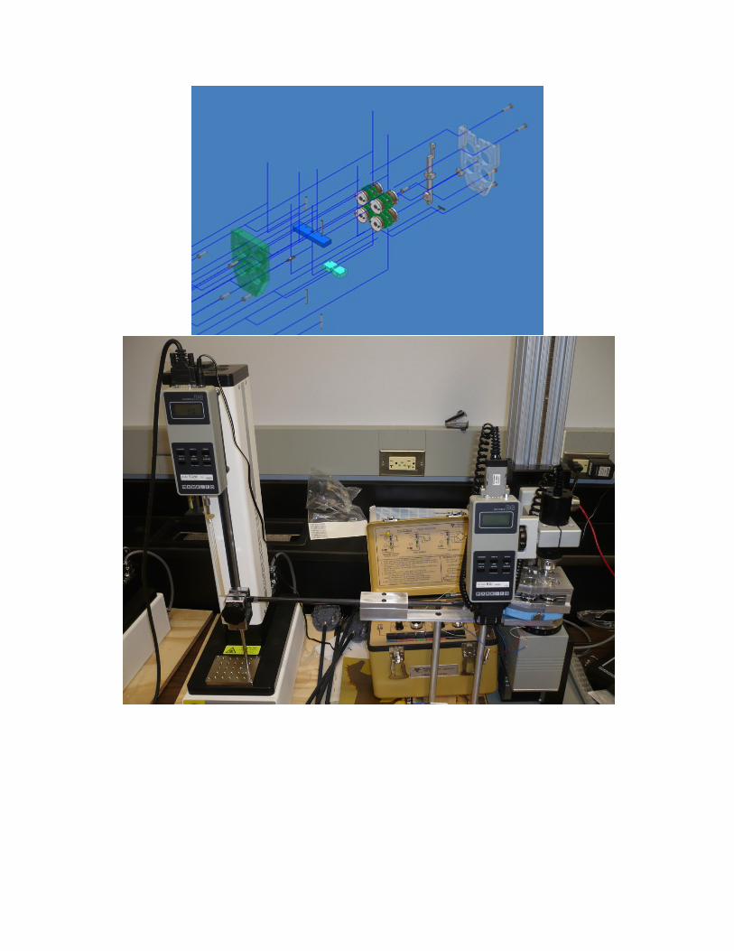
mechanism as shown below (Fig. 1). The steering mechanism is directly controlled by the user
via a handle and the wheels can turn up to 45 degrees.
Fig. 1 Steering mechanism
The body frame of Tri-pedalo is built with parts from a bicycle. When discussing the
manufacturing process with our machinist, George Luhrs, we found that using bicycle parts
would ease the process significantly. Components are then welded together and the frame is
painted red (Fig. 2). Since the use of crank shafts is the special feature of a Pedalo, it is preserved
into our design and installed with bearings and one gear and chain to ensure smooth and
effortless rotations. Plywood with oak is chosen to be the material for the pedals for its light
weight and attractive appearance. Rubber is adhered on the pedal surfaces to increase friction.
Fig. 2 Body Frame

Converging Savonius Wind Turbine
Designers: Kevin Lo, Alan Chesley, Robert Milinis
Instructor: Professor Zhou
Advisor: Professor Kincaid
Department of Mechanical Engineering
State University of New York at Stony Brook
Stony Brook, NY 11794-2300
INTRODUCTION
Our savonius turbine is similar to other savonius turbine that currently exists. It consists
of two scoops acting as the turbine blades connected to a rotating vertical shaft used for
converting the power of the wind into torque energy. However, our modification to our designs
depicts a governor that will help keep the turbine spinning at a desired speed no matter the wind
speed with the blades initially fully opened at rest and slowly converging when the desired of the
turbine speed is reached. Our goal is to have the turbine fully automated where it will expand its
blade at its rotating speeds lower than the desired, and then converging when the rotating speed
is reached or even exceeded.
SUMMARY OF IMPACT
The modification of the turbine governor design is to provide an automated mechanism
of safety for the machine. It is a simple design where it is purely mechanical and does not use
any computer devices. It is a complicated design to have calculated the forces necessary for the
desired action.
Its intention is to have it connected to a generator, then mounted to a roof of a complex
and able to produce power enough for a small home. It will be able to convert wind energy into
an electrical source for us to use will definitely be a huge step in saving the environment of its
depleting resources.
TECHNICAL DESCRIPTION
Our turbine blades are custom designed having the shape of a half a cylinder with a 14
inch diameter and a 40inch length. At the ends of the blade are pair of wheels that ride along a
rail attached to a top and bottom plate in which the turbine is enclosed in. This allows the
turbines to expand and converge when the desired rotating speed for it to open and close is

obtained. With the conditions set in the wind tunnel, we have chosen our operating wind speed
where the turbine is to converge is 25 miles per hour.
The turbine itself is constructed from the stovepipe sheet metal with lightweight plastic at
the top and bottom. The turbine is enclosed with a wooden plate on the top and bottom
providing the rails acting as guides for the motion for the turbine. In between the turbines
consist of a linkage system where weights are connected to. These weights are what make it
possible to govern the turbine. Similar to a speed governor, as the turbine increases in speed, the
weights will want to move to the outside of the turbine. Having the weights connected on the
opposite facing turbine, as the weights move to the outside, it will pull on the turbine, allowing
the motion we desire. Machining played a major part in this project in joining the pieces
together. Collars, clamps, rods, rail guides, and support beams were made in an attempt to have
successful results. The final prototype was successful at being able to turn at low wind speeds.
Throughout the course of design and construction, many obstacles had to be overcome.
The major problem was the budget we are limited to. In our design, some of the materials
chosen had to be reconsidered and other devices that we wanted to purchase had to be
manufactured. Testing was also difficult due to our time constraint.

J.E.S. Riser – Reversible Assistive Device for Stand-Up
Designers: Eddie Zheng, Sriya Adhya, and Jincheng Wu
Client Coordinator: Dr. Zhou
Supervising Professors: Dr. Anurag Purwar, Dr. Jeffrey Ge
Department of Mechanical Engineering
State University of New York at Stony Brook
Stony Brook, NY 11794-2300
Fig 1: 3D CAD Model Fig 2: Finished prototype
INTRODUCTION
This portable and reversible device is designed to raise the user from sitting to standing, and
vice-versa. It is specially aimed for a disabled patient, who lost his ability to stand up from
sitting due to a polio attack eight years ago. Moreover, it can help elderly people as well, who
have lost their physical strengths. A patient can use any remaining strength s/he has to activate
the device. The lifting mechanism is detachable and facilitated to be used in many types of
walkers.
SUMMARY OF IMPACT
This project is specially designed for Dr. Hari Pillai, who was diagnosed with polio at the age of
five. With that strike eight years ago, he has lost the strength to use his hip and legs. The only
capability he has is locking his knees to provide more stability. He cannot sit or stand in any
motion without great difficulty and discomfort. Dr. Pillai wants a mechanism that can lift him
safely, granting him to walk around without further assistance.
In addition, the weight constraint is one of the major concerns during the detailed design stage.
The design team foresees the importance of keeping this device to be simple and compact, while
it providing the same force to lift a 200lb person. During the testing with Dr. Pillai, it has shown

that the device can lift him from sitting to standing with good stability. With such a success, the
J.E.S. Riser has a great potential to be mass produced and sold to the elderly or patients with loss
of function related to the capability with standing.
TECHNICAL DESCRIPTION
Due to weight constraint matter, the device should be made simple by containing fewer parts.
Complexity in this device only serves to increase the overall weight and weaken the overall
structure as well. The walker itself is foldable. It is made by aluminum. The lifting/lowering
mechanism contains two 12V DC electromechanical actuators, with a maximum of 18” stroke
extension. The end rods of each actuator are pinned to two precisely machined aluminum
connectors. There is a soft pad that covers a plastic crutch, which is bolted to the connector at
each side of the walker. In addition, the circuitry is connected in a parallel circuit neatly across
the frame of the walker. The wires are covered by plastic tubes in a way to hold them in place
and out of a hassling way.
In making the operation process flexible, the switch housing is specially made. It is connected
on the upper left hand side of the walker within the optimum region of accessibility. One
housing contains two switches. The front switch is used to turn ON/OFF of the main power
supply. The back switch is used to control the UP/DOWN motion of the lifting mechanism.
Another housing mounted behind the left actuator motor is used to store the batteries and the
fuses.

Wheelcycle
Designers: Timothy R. Dugan, Alexander Slanover, Erik Venetsky
Supervising Professor: Dr. Imin Kao
Department of Mechanical Engineering
Stony Brook University
Stony Brook, NY 11794-2300
Fig 1: Wheelcycle Assembly Kit Fig 2: CAD Model of assembled
mechanism
Introduction
The Wheelcycle design has two main purposes, first to make moving in a wheelchair
easier by utilizing a pedaling motion, and second to allow a disabled person to perform
rehabilitation actions while seated in their normal wheelchair. Many wheelchair users find it
difficult to power the chair in the traditional way, by rotating the large rear wheels. Additionally
rehabilitation for disabled people often requires them to get out of their wheelchair and enter a
different device. The Wheelcycle seeks to fix these problems. The design would be based on
modifications to a standard model wheelchair. The design included no permanent bonding of
any parts to the chair. This allows the parts to be given as a kit; the user could simply attach
them to their own wheelchair.
Summary of Impact
The design will provided disabled people with two distinct benefits over a normal
wheelchair. The first is increased mobility. By providing a hand pedaling mechanism, the user
can more easily power the wheelchair. The second is rehabilitation. By converting into a foot
pedaled device, the disabled user could rehabilitate weak legs.
Technical Description
The Wheelcycle is a modification kit to a standard wheelchair. All parts are bolted or
clipped on to a wheelchair, allowing the user to use their own wheelchair. The design is robust
and allows for conversion onto different wheelchair frames. The main design is a hand powered
crank which transmits torque to the wheels through a series of gear-chain systems. All parts
have been manufactured out of steel.
The main mechanism is a pedaling device situated in between the user’s legs. The
pedaling device is modified from a bicycle’s pedal hub. The pedals are on the top of a 2’6” shaft.
The pedaling device can be swung up and down, allowing the user to power the chair using both
their hands and legs. The hand pedaling is to be used mainly for improved mobility while the
foot pedaling is used for rehabilitation purposes. The pedaling device has a crank attached to a
sprocket. The crank runs on the shaft through two ball bearings on each side. A standard bicycle
chain attached to the gear transmits power from the pedaling motion to the shaft mounted

underneath the chair. This shaft is a ½” steel rod. It is mounted on the chair through two ball
bearings which are bolted to the frame of the chair. This shaft extends beyond the frame in both
directions. There are two small gears on each side in order to power the wheels. These gears
also have standard bicycle chains on them. The chains are attached to two bicycle wheels on
each side. These wheels have a 5 gear hub on them. This allows for a change in gear ratio,
changing the amount of torque required to power the Wheelcycle. The Bicycle wheels have
rubber tires to improve the traction from the regular wheelchair wheels. There is also a braking
mechanism that has been adapted from a bicycle. When the user pulls a lever, a wire tightens
compressing two brake pads to stop the wheel.
The final prototype was designed with heavy consideration on the user being disables.
Therefore, ease of use and safety were paramount in the design. The device was designed to be
attached to a regular wheelchair, meaning a user would not have to purchase a completely new
chair. There were many more ideas that the designers desired to include but were forced to
remove due to time constraints. Some of these are safety devices, which with more time and
money, would defiantly be added.

Transformable Chair Cane
Designers: Zonglin Sun, Rongfeng Yu, Peisheng Zhang
Supervising Professor: Professor Yu Zhou
Department of Mechanical Engineering
State University of New York
Stony Brook, NY 11794
Folded View (Cane)
Introduction
The objective of this design project is to design a transformable cane that can also be used as a
chair that allows elderly and physical handicap individuals to sit on when it’s needed. Our design
will provide convenience for people especially those who are disabled and have hip problems to
help them join more outdoor activities. Different from other similar existing products, our design
has a better cane outlook which is one of the most important factors when customers pick their
canes.
Summary of Impact
Many elderly or individuals who have walking problems are forced to stay indoor due to their
inconvenience. Their legs are not strong enough for long distance walk or standing. Our design is
a walking assist tool and at the same time it can provide seat for the users anytime and anywhere.
Consequently, it greatly increases the users’ capabilities of outdoor activities.
Technical Description
The final design consists three major parts, cane body, inner linkage system and seat surface.
Each part is specially designed to satisfy design requirements. Many new features are added after
the first prototype; include the cane handle and the tip of the cane.
The cane body has the same outlook as a regular cane. However, it can be split into four quarter-
circle legs which are also used as chair legs. . There are hinges attached on the inner side of four
legs. The inner linkage system is major idea of this design. The linkage system has eight links,
one central rod and two cord join. The four legs are providing vertical support and the eight
cords are installed to prevent the legs from tipping. The material of the seat is nylon. It is
extremely strong since the seat has to support one person’s body weight without being torn apart.
The shape of the seat is particularly designed to minimize the volume, so it can be stored inside
the upper part of the cane body. The cane handle is designed face inward to the user. It provides
help for user to stand up from sit position.
The total cost of this design is approximately 560$ in terms of materials. Approximately 100
hours of labor between all group members. We ordered extra aluminum tube and steel rods to
prevent failure or accident during fabrication. Different seat materials are bought to perform
prototype test and stress analysis. With extra ordered materials, we can make two more
prototypes.

Bottom Folded View Cane Handle
Upper cane body Chair Top View (open) Chair Side View

Toilet Accessible Wheelchair
Designers: Hari Dutta and Sabir Dadachov
Supervising Professor: Professor Yu Zhou
Department of Mechanical Engineering
State University of New York at Stony Brook
Stony Brook NY, 11794-2300
Introduction
The objective of our design is to create a wheelchair that allows the users to access the toilet
without having to transfer themselves off the wheelchair and onto the toilet. This wheelchair will
allow users with moderate upper body strength to use the toilet without the use of any assistance
or the fear of losing balance and injuring themselves seriously in a fall.
Summary of Impact
The design allows users to back their wheelchair over most commonly found toilets, lock their
wheelchair in place and use the toilet like anybody else would. The opening created in the
wheelchair allows the user to feel the same support a toilet seat would provide. Significant
advantages of this design include the full support of a wheelchair seat that transforms into a well
supported toilet seat and the ability to eliminate waste directly into a toilet, rather than the
current technology that require a bag under the wheelchair that must be disposed of.
Technical Description
The design is based on a conventional wheelchair that is modified to allow an opening in the
middle of the seat from which the users can access the toilet beneath them. The entire frame was

rebuilt to our dimensions using aluminum. The frame can be considered to be two parts, the outer
frame and inner frame. The inner frame consists of two components, a tilt frame and slider frame.
The tilt frame allows the weight of the user to be taken off the slider frame so that the slider
frame is free to slide out and under the user. The slider frame, when removed, creates the
opening leading to the toilet bowl.

CT guided robotic needle gripper for lung biopsy
Designers: Brian Wong, Guangqiang Ao, Lang Lang
Supervising Professor: Dr. Yu Zhou
Department of Mechanical Engineering
State University of New York at Stony Brook
Stony Brook, NY 11794-2300
INTRODUCTION
Designing a robotic needle gripper and arm that will hold a lung biopsy needle and perform the
biopsy within the CT scanner may revolutionize how lung biopsies are taken. Using a needle
aspiration biopsy, cells from within the lungs can be easily obtained and is less invasive to the
patient and a quicker healing time. Also, the fact that the biopsy can be obtained during a CT
scan means the needle can be robotically moved to the exact location of a lung tumor or lesion in
a quick, medically precise fashion.
Nature of Impact
This gripper will fill the medical void of assisting in lung tumor diagnoses in a less invasive,
more precise, and expeditious manner, via robotics and plastics. The expected outcome is an
efficient method/mechanism for real time location of tumors in a CT scan. During the procedure
a patient is asked to hold his breath while a CT scan is done and then hold is breathe again while

needle biopsy takes place. For the average person, this is not a problem but a large percentage of
patients undergoing this procedure have some sort of lung condition that they are not able to hold
their breath. The needle aspiration biopsy is a quick and low cost procedure, while the alternative
is an open chest biopsy, which is costly, time-consuming and risky.
Technical description
The gripper arm is composed of several parts. The most important being the two 18 inch
long gripper arms that rotate around a central pivot. The whole project has been made out of
medical grade acetal which is a polymer and an industry standard for medical devices. The
importance of using the polymer is not to interfere with the CAT scan images. Also all fasteners
are made out of the same polymer. Attached to one end of the arms is a gripper used to hold the
needle in place during the procedure. The gripper uses a simple encompassing grip to hold the
needle which makes it easy to load and offers a quick release in the case of emergency. On the
other end of the arms, one arm is held in place by a pivot and the other arm is in a track that has
one degree of freedom. This other arm is powered by a linkage system that allows it to moves the
arm along the track and therefore opening and closing the gripper. The driving arm of the linkage
is moved by a simple RC hobby servo. This servo provides enough torque to hold the gripper
closed during surgery and enough speed to drop the needle in a hurry. The end fits into a 3” X 3”
5” frame that is then attached to the robotic arm. The robotic arm will be used to manipulate the
gripper and insert the needle into the tumor while an active CAT scan is being preformed.

![Automated Extraction of Surgical Needles from Tissue Phantoms · da Vinci [12] and the Raven-II surgical robot [8]. The surgeon exercises full control and oversight of the robot’s](https://static.fdocuments.net/doc/165x107/5f310977adaca971f66e4df5/automated-extraction-of-surgical-needles-from-tissue-phantoms-da-vinci-12-and.jpg)