Torque Limiters 45 - GORACO6 Ratcheting SIKUMAT with screw faces The Screw Face Principle Torque...
72
RINGSPANN® Registered Trademark of RINGSPANN GmbH, Bad Homburg 45 Torque Limiters
Transcript of Torque Limiters 45 - GORACO6 Ratcheting SIKUMAT with screw faces The Screw Face Principle Torque...
RINGSPANN® Registered Trademark of RINGSPANN GmbH, Bad Homburg
45
Torque Limiters

2
Why RINGSPANN Torque Limiters?
Overview RINGSPANN Torque Limiters
Ratcheting SIKUMAT® with screw faces
Series SC - flange designSeries SCE - with flexible shaft couplingSeries SCL - with torsionally rigid shaft
couplingProximity switch for Ratcheting SIKUMAT®with screw faces
Ratcheting SIKUMAT® with balls
Series SG - flange designSeries SGR - with short hub and integral
needle bearingSeries SGG - with long hubSeries SGE - with flexible shaft coupling
Ratcheting SIKUMAT® - Backlash freewith balls
Series ST - flange designSeries STG - with long hubSeries STE - with flexible shaft couplingSeries STL - with torsionally rigid shaft
coupling
Synchronous Ratcheting SIKUMAT® with single rollers
Series SN - flange designSeries SNR - with short hub and integral
bearingSeries SNG - with long hubSeries SNE - with flexible shaft coupling
Synchronous Ratcheting SIKUMAT® with double rollers
Series SA - flange designSeries SAG - with long hubSeries SAE - with flexible shaft couplingSeries SAL - with torsionally rigid shaft
coupling
3
4
6
89
10
11
12
1415
1617
18
20212223
24
2627
2829
30
32333435
36
38394041
42
4445
4647
48
50515253
54
5657
5859
60
6061
62
636465
66
67
68
69
70
Synchronous Ratcheting SIKUMAT®- Backlash free with balls
Series SU - flange designSeries SUG - with long hubSeries SUE - with flexible shaft couplingSeries SUL - with torsionally rigid shaft
coupling
Disengaging SIKUMAT® with single rollers
Series SR - flange designSeries SRR - with short hub and integral
needle bearingSeries SRG - with long hubSeries SRE - with flexible shaft coupling
Synchronous Disengaging SIKUMAT® with double rollers
Series SB - flange designSeries SBG - with long hubSeries SBE - with flexible shaft couplingSeries SBL - with torsionally rigid shaft
coupling
Non-disengaging SIKUMAT® with single rollers
Series SL - flange designSeries SLR - with short hub and integral
needle bearingsSeries SLG - with long hubSeries SLE - with flexible shaft coupling
SIKUMAT® Proximity Switch
Non-contact SIKUMAT® Proximity SwitchMechanical SIKUMAT® Proximity Switch
RIMOSTAT® Torque Limiter
Series RSSeries RS - with chain wheelSeries RSC - with flexible chain coupling
Belleville Spring Torque Limiter
Series RT
Calculation of RIMOSTAT®-Torque Limiters
Comparison Table of current Torque Limiters
Selection sheet for RINGSPANN Torque Limiters
Page Page
SIKUMAT®
RIMOSTAT®
Registered Trademarks of RINGSPANN GmbH, Bad Homburg
Index
Issue 02/2007 - we reserve the right to make technical modifications

33
Why RINGSPANN Torque Limiters?
The more comprehensive the au-tomation of machines and installa-tions, the safer their operational func-tion needs to be. Blockages or over-loads should never be cause for thedestruction of operationally impor-tant components. Stoppages mustbe kept to a minimum so that theproduction process continues asquickly as possible and withoutcostly repairs. After all, shorter down-times mean higher productivity.
RINGSPANN Torque Limiters are me-chanical safety devices which discon-nect the output from the input whena preset limit value has beenreached. Thus they protect againstdamage and stoppage times causedby overload.
For over 40 years RINGSPANN hasmanufactured Torque Limiters withan excellent track record in the most diverse applications. TodayRINGSPANN offers a comprehensiverange of positive and friction TorqueLimiters.
Positive SIKUMAT Torque Limiters areused as precision safety devices in in-stallations and machines. The unsur-passed variety of working principlesoffer optimal solutions to every typeof application:
• SIKUMAT with screw faces for par-ticularly heavy-duty operating con-ditions,
• SIKUMAT with double rollers forhigh consistency of the limittorque over the duration of the op-erating period,
• SIKUMAT with balls for very highresponse accuracy as well as forbacklash free transmission oftorque and
• SIKUMAT with single rollers for uni-versal application conditions.
Friction Torque Limiters are availablein two designs:
• RIMOSTAT Torque Limiters for hightorque consistency even duringfrequent slipping and
• Belleville Spring Torque Limiters forparticularly cost effective solutions.
RINGSPANN supplies not only TorqueLimiters but can also offer compre-hensive advice and service.RINGSPANN provides the securityyou need.

4
Po
siti
ve lo
ckin
gFr
icti
on
lo
ckin
g
Overview RINGSPANN Torque Limiters
Torque limiting by
Re-engagement Consistency of torque limiting
over operating period
Back-lashfree
dis -engaging
ratchet-ing
proximityswitch
slipping auto-matic
manually
manuallysynchro-
nouslyafter360°
automaticsynchro-
nouslyafter360°
veryhigh
high medium low
Ratcheting SIKUMATwith screw faces
Series: SC, SCE and SCL
Ratcheting SIKUMATwith balls
Series: SG, SGR, SGG and SGE
Ratcheting SIKUMAT –Backlash freewith balls
Series: ST, STG, STE and STL
Synchronous RatchetingSIKUMAT with single rollers
Series: SN, SNR, SNG and SNE
Synchronous RatchetingSIKUMAT with double rollers
Series: SA, SAG, SAE and SAL
Synchronous RatchetingSIKUMAT – Backlash freewith balls
Series: SU, SUG, SUE and SUL
Disengaging SIKUMAT with single rollers
Series: SR, SRR, SRG and SRE
Synchronous DisengagingSIKUMAT with double rollers
Series: SB, SBG, SBE and SBL
Locking SIKUMAT with single rollers
Series: SL, SLR, SLG and SLE
RIMOSTAT Torque Limiter
Series: RS and RSC
Belleville Spring TorqueLimiter
Series: RT
10 102 103 104 103 104 105[mm]
6
12
18
24
30
36
42
48
54
62
66
45
65
60
65
125
60
65
125
65
115
120
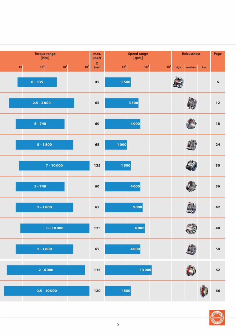
6 - 335 1 500
3 300
4 000
1 000
1 500
4 000
5 000
6 000
4 000
13 000
1 500
2,5 - 2 000
5 - 740
5 - 740
5 - 1 800
5 - 1 800
5 - 1 800
0,5 - 10 000
7 - 10 000
8 - 10 000
2 - 6 000
5
mediumhigh low
Robustness PageTorque range [Nm]
Speed range [rpm]
max.shaft
ø[mm]

66
Ratcheting SIKUMATwith screw faces
The Screw Face Principle
Torque transmission is effectedthrough screw-shaped radial serra-tions in the input and output part,which are pressed together by springforce. Like the thread sides of a screwhave edge contact with the nut dur-ing turning, so the toothed flanks ofthe SIKUMAT retain their surface con-tact even during the torque disen-gaging process. This characteristicgives the SIKUMAT an extremely highresistance against wear and there-fore a long operating life.
Advantages
• Excellent robustness through sur-face contact during the disengag-ing process – therefore maximumlife
• Fully enclosed with integral bear-ing – therefore maintenance-free
• Protection against unauthorisedadjustment of the torque settingachieved by the fixed stop of thethreaded ring
• Adjustment of limit torque settingaccording to the number of activesprings – not through modificationof spring pressure
Function
• When reaching the preset limittorque the SIKUMAT ratchets.
• After elimination of the overloadthe SIKUMAT re-engages automati-cally.
• The overload can be indicated bythe special proximity switch for theratcheting SIKUMAT with screwfaces, thus either causing the driveto be switched off instantly or an-other control function to be acti-vated.
Function
engaged disengaged
Face gear
The toothed flanks main-tain surface contact onlywhen engaged.
Comparison of function principles
Screw face
The toothed flanksmaintain surface con-tact even during the dis-engaging.

77
Ratcheting SIKUMATwith screw faces
For attaching chain wheels, belt pul-leys, gear wheels etc. Bearing of at-tached component on the shaft to beprovided by the customer.
Types
NotesTorque setting
Normally the limit torque is set at thefactory. Setting or modification of thelimit torque can be carried out by thecustomer but no unauthorised ad-justment should be made by the ma-chine operator. See operating in-structions for further details.
Proximity switch
The proximity switch for the ratchet-ing SIKUMAT with screw faces indi-cates overload by non-contactmeans with an inductive proximityswitch. See page 11 for details.
For flexible connection of two shafts.The flexible elements are oil-proof.
For rigid connection of two shafts.Possibility to compensate for largeradial and angular displacements.
Speed Control ESC
The RINGSPANN speed control ESC(Electronic Speed Control) monitorsspeed deviations and speed differ-ences safely and also under difficultoperating conditions. See catalogue50.1 for details.
Page 8
Page 9
Page 10
Series SC - flange design
Series SCE - with flexible shaft coupling
Series SCL - with torsionally rigid shaft coupling
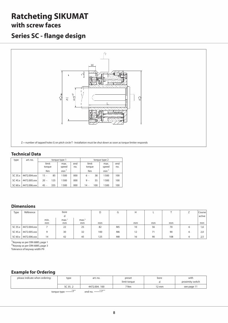
SC 35.x 4472.004.xxx 7 22 25 82 M5 10 56 70 6 1,6
SC 45.x 4472.005.xxx 9 30 32 100 M6 12 71 90 6 2,0
SC 60.x 4472.006.xxx 14 42 45 125 M8 16 90 108 6 2,5
D G H L T Z
d
min. max.1) max.2)
mm mm mm mm mm mm mm
88
SC 35.x 4472.004.xxx 15 - 85 1 500 000 6 - 38 1 500 100
SC 45.x 4472.005.xxx 20 - 125 1 500 000 9 - 55 1 500 100
SC 60.x 4472.006.xxx 45 - 335 1 500 000 14 - 100 1 500 100
SC 35. 2 4472.004. 100 7 Nm 12 mm
d
type art. no. torque type 1 torque type 2
limit max. end limit max. endtorque speed no. torque speed no.
Nm min-1 Nm min-1
Ratcheting SIKUMATwith screw faces
Series SC - flange design
Z = number of tapped holes G on pitch circle T · Installation must be shut down as soon as torque limiter responds
torque type end no.
please indicate when ordering: type art. no. preset bore with
limit torque proximity switch
see page 11
1)Keyway as per DIN 6885, page 12)Keyway as per DIN 6885, page 3Tolerance of keyway width P9
Technical Data
Example for Ordering
Dimensions
mm
Type Référence Course
active
bore

99
SCE 35.x 4472.604.xxx 7 22 25 10 45 114 82 72 56 131 28 19 48 1,6
SCE 45.x 4472.605.xxx 9 30 32 10 50 127 100 78 71 151 31 20 52 2,0
SCE 60.x 4472.606.xxx 14 42 45 20 60 158 125 96 90 188 39 21 61 2,5
A D E L O U V Z3d1 d2
min. max.1) max.2) min. max.1)
mm mm mm mm mm mm mm mm mm mm mm mm mm
SCE 35.x 4472.604.xxx 15 - 85 1 500 000 6 - 38 1 500 100
SCE 45.x 4472.605.xxx 20 - 125 1 500 000 9 - 55 1 500 100
SCE 60.x 4472.606.xxx 45 - 335 1 500 000 14 - 100 1 500 100
SCE 35. 2 4472.604. 100 7 Nm 12 mm 15 mm
d1 d2
borebore
type art. no. torque type 1 torque type 2
limit max. end limit max. endtorque speed no. torque speed no.
Nm min-1 Nm min-1
torque type end no.
typeplease indicate when ordering: art. no. preset bore bore with
limit torque proximity switch
see page 11
mm
Type Référence Course
active
Ratcheting SIKUMATwith screw faces
Series SCE - with flexible shaft coupling
Z = number of tapped holes G on pitch circle T · Installation must be shut down as soon as torque limiter responds
1)Keyway as per DIN 6885, page 12)Keyway as per DIN 6885, page 3Tolerance of keyway width P9
Technical Data
Example for Ordering
Dimensions
1010
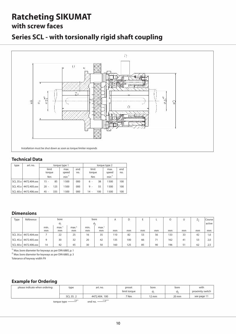
SCL 35.x 4472.404.xxx 7 22 25 16 35 110 82 53 56 133 33 42 1,6
SCL 45.x 4472.405.xxx 9 30 32 20 42 135 100 66 71 162 41 53 2,0
SCL 60.x 4472.406.xxx 14 42 45 30 50 160 125 85 90 196 51 62 2,5
A D E L O U Z2d1 d3
min. max.1) max.2) min. max.1)
mm mm mm mm mm mm mm mm mm mm mm mm
SCL 35.x 4472.404.xxx 15 - 85 1 500 000 6 - 38 1 500 100
SCL 45.x 4472.405.xxx 20 - 125 1 500 000 9 - 55 1 500 100
SCL 60.x 4472.406.xxx 45 - 335 1 500 000 14 - 100 1 500 100
SCL 35. 2 4472.404. 100 7 Nm 12 mm 20 mm
d1 d3
Ratcheting SIKUMATwith screw faces
Series SCL - with torsionally rigid shaft coupling
Installation must be shut down as soon as torque limiter responds
type art. no. torque type 1 torque type 2
limit max. end limit max. endtorque speed no. torque speed no.
Nm min-1 Nm min-1
torque type end no.
typeplease indicate when ordering: art. no. preset bore bore with
limit torque proximity switch
see page 11
1) Max. bore diameter for keyways as per DIN 6885, p. 12) Max. bore diameter for keyways as per DIN 6885, p. 3
Tolerance of keyway width P9
Technical Data
Example for Ordering
Dimensions
mm
Type Référence Course
active
bore bore

1111
35
45
60
Tmm
57,5
65,0
77,5
hmm
21
32
47
X
3504.000.097.B024VG
2504.000.001.A00002
size
Proximity switch for Ratcheting SIKUMAT with screw faces
Notes
The proximity switch is supplied withan aluminium support bracket whichis fastened with 2 screws M6 accord-ing to the drawing. The fasteningmust be non-oscillating. Once in-stalled, the torque limiter’s maximumpermissible axial movement towardsthe proximity switch is 0,2 mm.
Effect
The proximity switch’s response to anoverload is to react on the switchingdisc located internally. During normaloperation the proximity switch isclosed, the yellow LED is illuminated.The switching disc moves as the pre-set limit torque is reached. The prox-imity switch opens and the yellowLED goes out. A speed-dependentswitching sequence is triggered atthe output end of the limit sensor.
Technical Data
Operating voltage: 24 V DC ±20%
Output: PNP-Transistor
Max. switching current: 200 mA
Internal powerconsumption: 10 mA
Protection type: IP 67
Ambienttemperature: -25° ... +75° C
Dimensions (H x L x W): 23 x 35 x 14 mm
type
Proximity switch with plug connection
Attaching plug, 90º, incl. 2 m PVC cable
art. no.
View X

1212
F F
F F
Ratcheting SIKUMATwith balls
The Ball Principle
The torque is transmitted via ballswhich are pressed into detents viaBelleville springs. When the presetlimit torque has been reached theballs rise out of their seatings andslot into the nearest respective de-tent – until the overload has beeneliminated. This characteristic, to-gether with the special geometry ofthe detent gives the SIKUMAT a veryhigh response accuracy.
Advantages
• Very high response accuracythrough the ball principle
• Integrated fixed bearing
• Keyway in connecting flange formaximum load capacity
• Calibrated micro adjustment oftorque setting possible, even post-installation
• Exchange of current torque limiterspossible
• Cost effective
Function
engaged
disengaged
Function
• When the preset limit torque hasbeen reached the SIKUMAT ratch-ets.
• Automatic re-engagement of theSIKUMAT after the overload hasbeen eliminated.
• The overload can be indicated by aproximity switch. This means thatthe drive can be switched off im-mediately or another control func-tion can be activated.

1313
Ratcheting SIKUMATwith balls
Types
NotesTorque setting
If requested, the limit torque can beset at the factory. Setting or modifica-tion of the limit torque can also becarried out by the customer. See op-erating instructions for further de-tails.
Proximity switch
An overload can be indicated by anon-contact or a mechanical proxim-ity switch. Further details on pages60 and 61.
With short hub and needle bearingfor narrow components to be con-nected
With long hub for wide componentsto be connected. Bearing of the at-tached component in the form ofplain or needle bearing to be pro-vided by the customer.
Page 14
Page 15
Page 16
Speed Control ESC
The RINGSPANN speed control ESC(Electronic Speed Control) monitorsspeed deviations and speed differ-ences safely and also under difficultoperating conditions. See catalogue50.1 for details.
Page 17
For attaching chain wheels, belt pul-leys, gear wheels etc. Bearing of at-tached component on the shaft to beprovided by the customer.
For flexible connection of two shafts.The flexible components are oilproof.
Series SG - flange design
Series SGG - with long hub
Series SGR - with short hub and integral needle bearing
Series SGE - with flexible shaft coupling

1414
SG 32.x 4478.020.xxx 7 20 55 41 50 M5 6,5 3 9 13,5 35 38,5 6 3,1 48 38,5 5 6 1,4
SG 40.x 4478.025.xxx 10 25 82 60 72,5 M5 8 6 9 14,5 48 52 6 3,1 70 54 6 6 2,3
SG 55.x 4478.035.xxx 14 35 100 78 90,5 M6 10 6 9 15 56 61 8 3,6 89 70 6 6 2,4
SG 65.x 4478.045.xxx 18 45 120 90,5 112 M8 12 8,5 10 22,5 72 78 10 4,1 105 84 6 6 2,7
SG 80.x 4478.055.xxx 24 55 146 105 140 M10 15 11 9 25 93,5 100 12 4,1 125 108 7 6 3,7
SG 90.x 4478.065.xxx 30 701) 176 120,5 170 M12 17 12 9 30 107 113,5 14 4,6 155 129 10 6 4,6
D F F3 G H J K K1 L L0 N N1 T X Y Z
d
min. max.mm mm mm mm mm mm mm mm mm mm mm mm mm mm mm mm
SG 32.x 4478.020.xxx 2,5 - 5 3 300 001 5 - 10 3 300 002 10 - 20 1 800 003 20 - 40 1 800 004
SG 40.x 4478.025.xxx 6 - 12 2 900 001 12 - 25 2 900 002 25 - 55 1 450 003 55 - 100 1 450 004
SG 55.x 4478.035.xxx 12 - 25 2 400 001 25 - 50 2 400 002 50 - 120 1 200 003 120 - 200 1 200 004
SG 65.x 4478.045.xxx 25 - 50 2 000 001 50 - 100 2 000 002 100 - 250 1 000 003 200 - 450 1 000 004
SG 80.x 4478.055.xxx 50 - 100 1 600 001 100 - 200 1 600 002 200 - 500 850 003 500 - 1 000 850 004
SG 90.x 4478.065.xxx 85 - 250 1 400 001 230 - 600 1 400 002 300 - 1 000 700 003 600 - 2 000 700 004
SG 32. 2 4478.020. 002 7 Nm 12 mm
d
Ratcheting SIKUMATwith balls
Series SG - flange design
Z = number of tapped holes G on pitch circle T · Installation must be shut down as soon as torque limiter responds
Keyway as per DIN 6885, page 1 · Tolerance of keyway width JS91) Keyway as per DIN 6885, page 3 · Tolerance of keyway width JS9
mm
Type Référence Course
active
bore
see p. 60 and 61
torque type end no.
please indicate when ordering: type art. no. preset bore with
limit torque proximity switch
Example for Ordering
Dimensions
type art. no. torque type 1 torque type 2 torque type 3 torque type 4
limit max. end limit max. end limit max. end limit max. endtorque speed no. torque speed no. torque speed no. torque speed no.
Nm min-1 Nm min-1 Nm min-1 Nm min-1
Technical Data
keyway width N
1 x between 2 tapped holes

1515
SGR 32.x 4478.920.xxx 7 20 21 55 38 50 M5 11,5 3 9 13,5 51,5 8 15 48 38,5 5 6 1,4
SGR 40.x 4478.925.xxx 10 25 26 82 50 72,5 M5 16 6 9 14,5 70 10 20 70 54 6 6 2,3
SGR 55.x 4478.935.xxx 14 35 36 100 60 90,5 M6 15 6 9 15 78 12 25 89 70 6 6 2,4
SGR 65.x 4478.945.xxx 18 45 46 120 80 112 M8 18 8,5 10 22,5 96 12 30 105 84 6 6 2,7
SGR 80.x 4478.955.xxx 24 55 56 146 100 140 M10 23,5 11 9 25 124,5 16 30 125 108 7 6 3,7
SGR 90.x 4478.965.xxx 30 701) 66 176 120 170 M12 25,5 12 9 30 140 18 30 155 129 10 6 4,6
d5 D F1 F3 G H1 J K K1 L2 Q1 R1 T X Y Z
d
min. max.mm mm mm mm mm mm mm mm mm mm mm mm mm mm mm mm
SGR 32.x 4478.920.xxx 2,5 - 5 3 300 001 5 - 10 3 300 002 10 - 20 1 800 003 20 - 40 1 800 004
SGR 40.x 4478.925.xxx 6 - 12 2 900 001 12 - 25 2 900 002 25 - 55 1 450 003 55 - 100 1 450 004
SGR 55.x 4478.935.xxx 12 - 25 2 400 001 25 - 50 2 400 002 50 - 120 1 200 003 120 - 200 1 200 004
SGR 65.x 4478.945.xxx 25 - 50 2 000 001 50 - 100 2 000 002 100 - 250 1 000 003 200 - 450 1 000 004
SGR 80.x 4478.955.xxx 50 - 100 1 600 001 100 - 200 1 600 002 200 - 500 850 003 500 - 1 000 850 004
SGR 90.x 4478.965.xxx 85 - 250 1 400 001 230 - 600 1 400 002 300 - 1 000 700 003 600 - 2 000 700 004
SGR 32. 2 4478.920. 002 7 Nm 12 mm
d
bore
Z = number of tapped holes G on pitch circle T · Installation must be shut down as soon as torque limiter responds
Ratcheting SIKUMATwith balls
Series SGR - with short hub and integral needle bearing
type art. no. torque type 1 torque type 2 torque type 3 torque type 4
limit max. end limit max. end limit max. end limit max. endtorque speed no. torque speed no. torque speed no. torque speed no.
Nm min-1 Nm min-1 Nm min-1 Nm min-1
Technical Data
Dimensions
mm
Type Référence Course
active
Keyway as per DIN 6885, page 1 · Tolerance of keyway width JS91) Keyway as per DIN 6885, page 3 · Tolerance of keyway width JS9
see p. 60 and 61
torque type end no.
please indicate when ordering: type art. no. preset bore with
limit torque proximity switch
Example for Ordering

1616
SGG 32.x 4478.120.xxx 7 20 21 4 55 41 28 50 M5 6,5 3 9 13,5 66 27,5 25,5 48 38,5 5 6 1,4
SGG 40.x 4478.125.xxx 10 25 26 4 82 60 38 72,5 M5 8 6 9 14,5 83 33 35 70 54 6 6 2,3
SGG 55.x 4478.135.xxx 14 35 36 5 100 78 52 90,5 M6 10 6 9 15 100 39 45 89 70 6 6 2,4
SGG 65.x 4478.145.xxx 18 45 46 5 120 90,5 65 112 M8 12 8,5 10 22,5 125 47 59 105 84 6 6 2,7
SGG 80.x 4478.155.xxx 24 55 56 6,5 146 105 78 140 M10 15 11 9 25 152,5 52,5 60 125 108 7 6 3,7
SGG 90.x 4478.165.xxx 30 701)66 6,5 176 120,5 90 170 M12 17 12 9 30 171 57,5 60 155 129 10 6 4,6
SGG 32.x 4478.120.xxx 2,5 - 5 3 300 001 5 - 10 3 300 002 10 - 20 1 800 003 20 - 40 1 800 004
SGG 40.x 4478.125.xxx 6 - 12 2 900 001 12 - 25 2 900 002 25 - 55 1 450 003 55 - 100 1 450 004
SGG 55.x 4478.135.xxx 12 - 25 2 400 001 25 - 50 2 400 002 50 - 120 1 200 003 120 - 200 1 200 004
SGG 65.x 4478.145.xxx 25 - 50 2 000 001 50 - 100 2 000 002 100 - 250 1 000 003 200 - 450 1 000 004
SGG 80.x 4478.155.xxx 50 - 100 1 600 001 100 - 200 1 600 002 200 - 500 850 003 500 - 1 000 850 004
SGG 90.x 4478.165.xxx 85 - 250 1 400 001 230 - 600 1 400 002 300 - 1 000 700 003 600 - 2 000 700 004
SGG 32. 2 4478.120. 002 7 Nm 12 mm
d5 B D F F1 F3 G H J K K1 L1 Q R T X Y Z
d
min. max.mm mm mm mm mm mm mm mm mm mm mm mm mm mm mm mm mm mm
d
Ratcheting SIKUMATwith balls
Series SGG - with long hub
Z = number of tapped holes G on pitch circle T · Installation must be shut down as soon as torque limiter responds
bore
type art. no. torque type 1 torque type 2 torque type 3 torque type 4
limit max. end limit max. end limit max. end limit max. endtorque speed no. torque speed no. torque speed no. torque speed no.
Nm min-1 Nm min-1 Nm min-1 Nm min-1
Technical Data
Dimensions
mm
Type Référence Course
active
Keyway as per DIN 6885, page 1 · Tolerance of keyway width JS91) Keyway as per DIN 6885, page 1 · Tolerance of keyway width JS9
see p. 60 and 61
torque type end no.
please indicate when ordering: type art. no. preset bore with
limit torque proximity switch
Example for Ordering

SGE 32.x 4478.620.xxx 7 20 30 67 46 55 50 3 9 13,5 35 86 15 38,5 5 28 1,4
SGE 40.x 4478.625.xxx 10 25 50 112 79 82 72,5 6 9 14,5 48 137,5 38 54 6 58 2,3
SGE 55.x 4478.635.xxx 14 35 50 112 79 100 90,5 6 9 15 56 147 38 70 6 58 2,4
SGE 65.x 4478.645.xxx 18 45 60 128 90 120 112 8,5 10 22,5 72 176,5 45 84 6 67 2,7
SGE 80.x 4478.655.xxx 24 55 60 148 90 146 140 11 9 25 93,5 211,5 45 108 7 67 3,7
SGE 90.x 4478.665.xxx 30 701) 70 177 107 176 170 12 9 30 107 242,5 52 129 10 75 4,6
SGE 90.4 4478.665.xxx 30 701) 90 198 140 176 170 12 9 30 107 272 52 129 10 75 4,6
SGE 32.x 4478.620.xxx 2,5 - 5 3 300 001 5 - 10 3 300 002 10 - 20 1 800 003 20 - 40 1 800 004
SGE 40.x 4478.625.xxx 6 - 12 2 900 001 12 - 25 2 900 002 25 - 55 1 450 003 55 - 100 1 450 004
SGE 55.x 4478.635.xxx 12 - 25 2 400 001 25 - 50 2 400 002 50 - 120 1 200 003 120 - 200 1 200 004
SGE 65.x 4478.645.xxx 25 - 50 2 000 001 50 - 100 2 000 002 100 - 250 1 000 003 200 - 450 1 000 004
SGE 80.x 4478.655.xxx 50 - 100 1 600 001 100 - 200 1 600 002 200 - 500 850 003 500 - 1 000 850 004
SGE 90.x 4478.665.xxx 85 - 250 1 400 001 230 - 600 1 400 002 300 - 1 000 700 003 600 - 2 000 700 004
d2 A E D F3 J K K1 L O U X Y Z3d1
min. max. max.mm mm mm mm mm mm mm mm mm mm mm mm mm mm mm mm
SGE 32. 2 4478.620. 002 7 Nm 12 mm 25 mm
d1 d2
17
bore
Ratcheting SIKUMATwith balls
Series SGE - with flexible shaft coupling
Installation must be shut down as soon as torque limiter responds
type art. no. torque type 1 torque type 2 torque type 3 torque type 4
limit max. end limit max. end limit max. end limit max. endtorque speed no. torque speed no. torque speed no. torque speed no.
Nm min-1 Nm min-1 Nm min-1 Nm min-1
Technical Data
Dimensions
mm
Type Référence Course
active
Keyway as per DIN 6885, page 1 · Tolerance of keyway width JS91) Keyway as per DIN 6885, page 1 · Tolerance of keyway width JS9
torque type end no.
type
see pages 60 and 61
please indicate when ordering: art. no. preset bore bore with
limit torque proximity switch
Example for Ordering

18
F F
F F
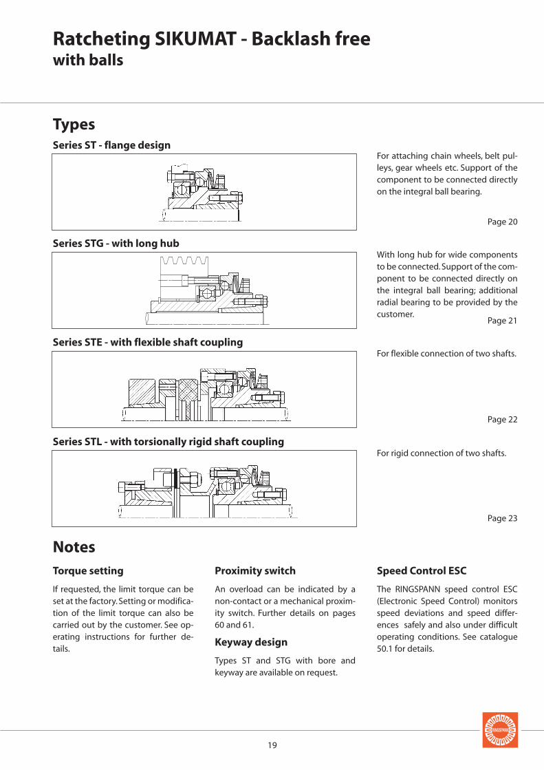
Ratcheting SIKUMAT - Backlash freewith balls
The Ball Principle -Backlash free
The torque is transmitted via ballswhich are pressed into V-shapedgrooves. The grooves are arrangedaxially on the output side and radiallyon the input side, which means thattorque can be trans mitted backlashfree in both directions of rotation. Asthe preset limit torque is reached, theballs rise out of the axial grooves andratchet into the respective next axialgroove – until the overload has beeneliminated. The negative characteris-tic disc springs give extremely fast,accurate and consistent overloadprotection.
Advantages
• Backlash free in both directions ofrotation
• Compact design
• Integral ball bearing for supportingthe component to be connected
• Very high response accuracythrough the ball principle
• Simple and backlash free fasteningonto shaft with integral coneclamping element
• Calibrated micro adjustment oftorque setting possible, even post-installation
• Exchange of current torque limiterspossible
Function
• When the preset limit torque hasbeen reached the SIKUMAT ratch-ets.
• Automatic re-engagement of theSIKUMAT after the overload hasbeen eliminated.
• The overload can be indicated by aproximity switch. This means thatthe drive can be switched off im-mediately or another control func-tion can be activated.
Function
engaged
disengaged
19
Ratcheting SIKUMAT - Backlash freewith balls
Series ST - flange design
Types
Series STE - with flexible shaft coupling
Series STG - with long hub
Series STL - with torsionally rigid shaft coupling
NotesTorque setting
If requested, the limit torque can beset at the factory. Setting or modifica-tion of the limit torque can also becarried out by the customer. See op-erating instructions for further de-tails.
Proximity switch
An overload can be indicated by anon-contact or a mechanical proxim-ity switch. Further details on pages60 and 61.
Keyway design
Types ST and STG with bore and keyway are available on request.
With long hub for wide componentsto be connected. Support of the com-ponent to be connected directly onthe integral ball bearing; additionalradial bearing to be provided by thecustomer.
For flexible connection of two shafts.
Page 20
Page 21
Page 22
Speed Control ESC
The RINGSPANN speed control ESC(Electronic Speed Control) monitorsspeed deviations and speed differ-ences safely and also under difficultoperating conditions. See catalogue50.1 for details.
Page 23
For attaching chain wheels, belt pul-leys, gear wheels etc. Support of thecomponent to be connected directlyon the integral ball bearing.
For rigid connection of two shafts.

20
ST 30.x 4479.025.xxx 10 20 65 63 40,5 5 47 70 M4 7,5 7 12 26 47 40 8 56 8 1,2
ST 30.x 4479.025.xxx 19 25 65 63 42 5 47 70 M4 7,5 7 12 26 47 40 8 56 8 1,2
ST 40.x 4479.030.xxx 15 30 80 77 57 7 62 85 M5 8 8 12 31 56 46 11 71 8 1,5
ST 45.x 4479.040.xxx 19 30 95 88 57 9 75 100 M6 10,5 9 14 40 67 57 14 85 8 1,8
ST 45.x 4479.040.xxx 32 40 95 88 64 9 75 100 M6 10,5 9 14 31 67 57 14 85 8 1,8
ST 55.x 4479.050.xxx 32 50 110 100 73,5 10 90 115 M6 12 10 16 29 73 63 16 100 8 2,0
ST 65.x 4479.060.xxx 32 50 130 122 73,5 10 100 135 M8 12 12 21 29 85 75 18 116 8 2,2
ST 65.x 4479.060.xxx 55 60 130 122 89 10 100 135 M8 12 12 21 45,5 86 75 18 116 8 2,2
D D1 D2 E F F3 G H K K1 L L0 L1 Q T Z
d*
min. max.mm mm mm mm mm mm mm mm mm mm mm mm mm mm mm mm
ST 30.x 4479.025.xxx 5 - 14 4 000 001 10 - 28 4 000 002 20 - 60 4 000 003
ST 40.x 4479.030.xxx 9 - 27 3 000 001 18 - 54 3 000 002 38 - 115 3 000 003
ST 45.x 4479.040.xxx 19 - 60 2 500 001 38 - 125 2 500 002 70 - 255 2 500 003
ST 55.x 4479.050.xxx 35 - 110 2 000 001 80 - 220 2 000 002 160 - 440 2 000 003
ST 65.x 4479.060.xxx 80 - 185 1 200 001 160 - 370 1 200 002 320 - 740 1 200 003
ST 40. 2 4479.030. 002 25 Nm 20 mm
d
Hub bore diameter d2 is equal to the selected diameter d and serves as an additional centering guide.*Available bore diameters d: 10, 11, 12, 14, 15, 16, 18, 19, 20, 22, 24, 25, 28, 30, 32, 35, 38, 40, 42, 45, 48, 50, 55 and 60 mm.
Ratcheting SIKUMAT - Backlash freewith balls
Series ST - flange design
Z = number of tapped holes G on pitch circle T · Installation must be shut down as soon as torque limiter responds
type art. no. torque type 1 torque type 2 torque type 3
limit max. end limit max. end limit max. endtorque speed no. torque speed no. torque speed no.
Nm min-1 Nm min-1 Nm min-1
Technical Data
Dimensions
mm
Type Référence Course
active
see p. 60 and 61
torque type end no.
please indicate when ordering: type art. no. preset bore with
limit torque proximity switch
Example for Ordering
bore

21
STG 30.x 4479.125.xxx 10 20 65 63 40,5 5 47 30 70 M4 7,5 7 12 26 72 33 6,5 56 8 1,2
STG 30.x 4479.125.xxx 19 25 65 63 42 5 47 30 70 M4 7,5 7 12 26 72 33 6,5 56 8 1,2
STG 40.x 4479.130.xxx 15 30 80 77 57 7 62 40 85 M5 8 8 12 31 88 43 8,75 71 8 1,5
STG 45.x 4479.140.xxx 19 30 95 88 57 9 75 45 100 M6 10,5 9 14 40 108 55 11,5 85 8 1,8
STG 45.x 4479.140.xxx 32 40 95 88 64 9 75 45 100 M6 10,5 9 14 31 108 55 11,5 85 8 1,8
STG 55.x 4479.150.xxx 32 50 110 100 73,5 10 90 55 115 M6 12 10 16 29 124 67 13 100 8 2,0
STG 65.x 4479.160.xxx 32 50 130 122 73,5 10 100 65 135 M8 12 12 21 29 140 73 14 116 8 2,2
STG 65.x 4479.160.xxx 55 60 130 122 89 10 100 65 135 M8 12 12 21 45,5 141 73 14 116 8 2,2
D D1 D2 E F F1 F3 G H K K1 L L1 Q Q1 T Z
d*
min. max.mm mm mm mm mm mm mm mm mm mm mm mm mm mm mm mm mm
STG 30.x 4479.125.xxx 5 - 14 4 000 001 10 - 28 4 000 002 20 - 60 4 000 003
STG 40.x 4479.130.xxx 9 - 27 3 000 001 18 - 54 3 000 002 38 - 115 3 000 003
STG 45.x 4479.140.xxx 19 - 60 2 500 001 38 - 125 2 500 002 70 - 255 2 500 003
STG 55.x 4479.150.xxx 35 - 110 2 000 001 80 - 220 2 000 002 160 - 440 2 000 003
STG 65.x 4479.160.xxx 80 - 185 1 200 001 160 - 370 1 200 002 320 - 740 1 200 003
STG 65.1 4479.160. 001 90 Nm 60 mm
d
Diameter d2 at the end of the long hub is equal to the selected diameter d and serves as an additional centering.*Available bore diameters d: 10, 11, 12, 14, 15, 16, 18, 19, 20, 22, 24, 25, 28, 30, 32, 35, 38, 40, 42, 45, 48, 50, 55 and 60 mm.
Ratcheting SIKUMAT - Backlash freewith balls
Series STG - with long hub
Z = number of tapped holes G on pitch circle T · Installation must be shut down as soon as torque limiter responds
type art. no. torque type 1 torque type 2 torque type 3
limit max. end limit max. end limit max. endtorque speed no. torque speed no. torque speed no.
Nm min-1 Nm min-1 Nm min-1
Technical Data
Dimensions
mm
Type Référence Course
active
see p. 60 and 61
torque type end no.
please indicate when ordering: type art. no. preset bore with
limit torque proximity switch
Example for Ordering
bore

22
STE 30.x 4479.625.xxx 10 20 15 28 70 63 40,5 55 70 7 12 26 47 102 30 30 1,2
STE 30.x 4479.625.xxx 19 25 15 28 70 63 42 55 70 7 12 26 47 102 30 30 1,2
STE 40.x 4479.630.xxx 15 30 15 38 85 77 57 65 85 8 12 31 54,5 119,5 35 35 1,5
STE 45.x 4479.640.xxx 19 30 20 45 100 88 57 80 100 9 14 40 67 146 45 45 1,8
STE 45.x 4479.640.xxx 32 40 20 45 100 88 64 80 100 9 14 31 67 146 45 45 1,8
STE 55.x 4479.650.xxx 32 50 25 50 115 100 73,5 95 115 10 16 29 73 159 50 50 2,0
STE 65.x 4479.660.xxx 32 50 30 55 135 122 73,5 105 135 12 21 29 87 182 56 56 2,2
STE 65.x 4479.660.xxx 55 60 30 55 135 122 89 105 135 12 21 45,5 87 182 56 56 2,2
A D1 D2 E F3 K K1 L L0 O U Z3d* d3**
min. max.mm mm mm mm mm mm mm mm mm mm mm mm mm mm mm mm mm
STE 30.x 4479.625.xxx 5 - 14 4 000 001 10 - 28 4 000 002 20 - 60 4 000 003
STE 40.x 4479.630.xxx 9 - 27 3 000 001 18 - 54 3 000 002 38 - 115 3 000 003
STE 45.x 4479.640.xxx 19 - 60 2 500 001 38 - 125 2 500 002 70 - 255 2 500 003
STE 55.x 4479.650.xxx 35 - 110 2 000 001 80 - 220 2 000 002 160 - 440 2 000 003
STE 65.x 4479.660.xxx 80 - 185 1 200 001 160 - 370 1 200 002 320 - 740 1 200 003
STE 30. 1 4479.625. 001 10 Nm 12 mm 20 mm
d d3
Ratcheting SIKUMAT - Backlash freewith balls
Series STE - with flexible shaft coupling
Installation must be shut down as soon as torque limiter responds
type art. no. torque type 1 torque type 2 torque type 3
limit max. end limit max. end limit max. endtorque speed no. torque speed no. torque speed no.
Nm min-1 Nm min-1 Nm min-1
Technical Data
Dimensions
mm
Type Référence Course
active
torque type end no.
type
see pages 60 and 61
please indicate when ordering: art. no. preset bore bore with
limit torque proximity switch
Example for Ordering
bore bore
Hub bore diameter d2 is equal to the selected diameter d and serves as an additional centering guide.*Available bore diameters d: 10, 11, 12, 14, 15, 16, 18, 19, 20, 22, 24, 25, 28, 30, 32, 35, 38, 40, 42, 45, 48, 50, 55 and 60 mm.**Available bore diameters d3: 15, 16, 19, 20, 24, 25, 28, 30, 32, 35, 38, 40, 42, 45, 48, 50 and 55 mm.
23
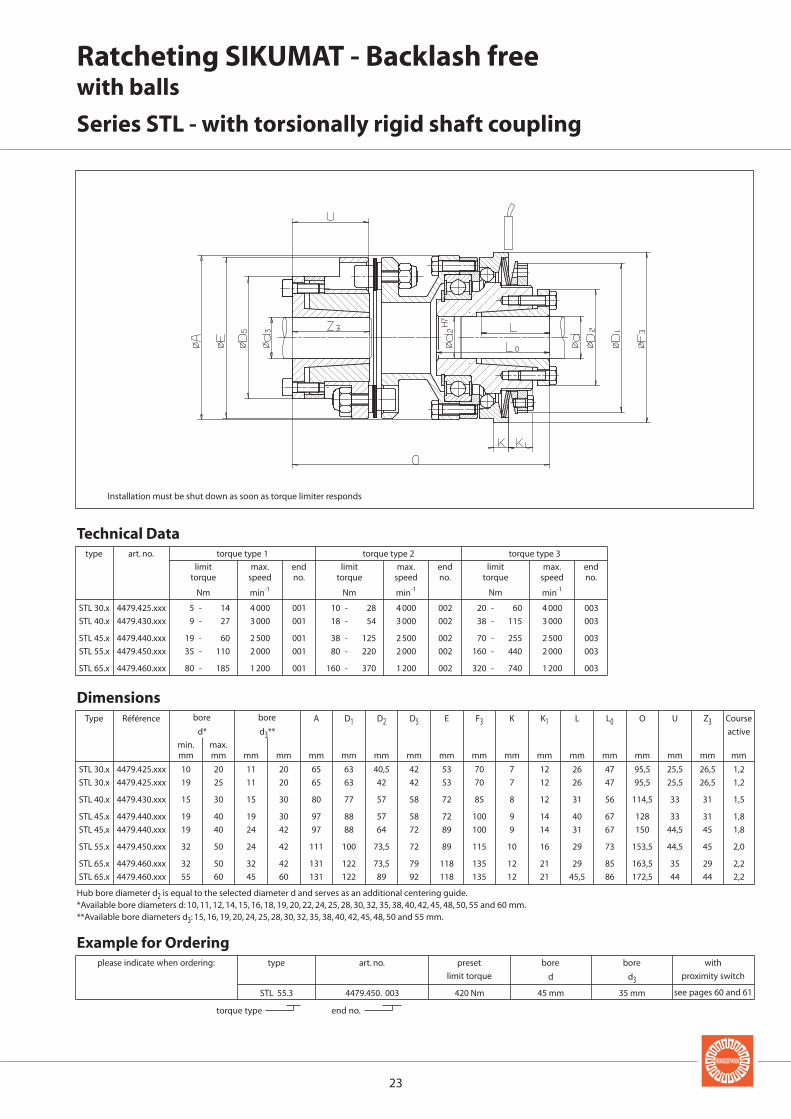
STL 30.x 4479.425.xxx 10 20 11 20 65 63 40,5 42 53 70 7 12 26 47 95,5 25,5 26,5 1,2
STL 30.x 4479.425.xxx 19 25 11 20 65 63 42 42 53 70 7 12 26 47 95,5 25,5 26,5 1,2
STL 40.x 4479.430.xxx 15 30 15 30 80 77 57 58 72 85 8 12 31 56 114,5 33 31 1,5
STL 45.x 4479.440.xxx 19 40 19 30 97 88 57 58 72 100 9 14 40 67 128 33 31 1,8
STL 45.x 4479.440.xxx 19 40 24 42 97 88 64 72 89 100 9 14 31 67 150 44,5 45 1,8
STL 55.x 4479.450.xxx 32 50 24 42 111 100 73,5 72 89 115 10 16 29 73 153,5 44,5 45 2,0
STL 65.x 4479.460.xxx 32 50 32 42 131 122 73,5 79 118 135 12 21 29 85 163,5 35 29 2,2
STL 65.x 4479.460.xxx 55 60 45 60 131 122 89 92 118 135 12 21 45,5 86 172,5 44 44 2,2
A D1 D2 D5 E F3 K K1 L L0 O U Z3d* d3**
min. max.mm mm mm mm mm mm mm mm mm mm mm mm mm mm mm mm mm
STL 30.x 4479.425.xxx 5 - 14 4 000 001 10 - 28 4 000 002 20 - 60 4 000 003
STL 40.x 4479.430.xxx 9 - 27 3 000 001 18 - 54 3 000 002 38 - 115 3 000 003
STL 45.x 4479.440.xxx 19 - 60 2 500 001 38 - 125 2 500 002 70 - 255 2 500 003
STL 55.x 4479.450.xxx 35 - 110 2 000 001 80 - 220 2 000 002 160 - 440 2 000 003
STL 65.x 4479.460.xxx 80 - 185 1 200 001 160 - 370 1 200 002 320 - 740 1 200 003
STL 55.3 4479.450. 003 420 Nm 45 mm 35 mm
d d3
Installation must be shut down as soon as torque limiter responds
Ratcheting SIKUMAT - Backlash freewith balls
Series STL - with torsionally rigid shaft coupling
type art. no. torque type 1 torque type 2 torque type 3
limit max. end limit max. end limit max. endtorque speed no. torque speed no. torque speed no.
Nm min-1 Nm min-1 Nm min-1
Technical Data
Dimensions
mm
Type Référence Course
active
torque type end no.
type
see pages 60 and 61
please indicate when ordering: art. no. preset bore bore with
limit torque proximity switch
Example for Ordering
bore bore
Hub bore diameter d2 is equal to the selected diameter d and serves as an additional centering guide.*Available bore diameters d: 10, 11, 12, 14, 15, 16, 18, 19, 20, 22, 24, 25, 28, 30, 32, 35, 38, 40, 42, 45, 48, 50, 55 and 60 mm.**Available bore diameters d3: 15, 16, 19, 20, 24, 25, 28, 30, 32, 35, 38, 40, 42, 45, 48, 50 and 55 mm.

2424
F F
F F
Synchronous Ratcheting SIKUMATwith single rollers
The Single Roller Principle
The torque is transmitted via rollerswhich are pressed by Bellevillesprings into detents. When the presetlimit torque has been reached, thedetent ring is axially displaced. Re-engagement is effected synchro-nously after 360º due to the asym-metrical division of the detents.
Advantages
• Synchronous re-engagement after360º
• Integral fixed bearing
• Driving keyway in the connectingflange for maximum load capacity
• Calibrated micro adjustment oftorque setting possible, even post-installation
• Exchange of current torque limiterspossible
• Cost effective
Function
• When the preset limit torque hasbeen reached the SIKUMAT ratch-ets.
• Following elimination of overloadautomatic synchronous re-engage-ment of the SIKUMAT to the start-ing position after 360º.
• The overload can be indicated by aproximity switch. This means thatthe drive can be switched off im-mediately or another control func-tion can be activated.
Function
engaged
disengaged

2525
Synchronous Ratcheting SIKUMATwith single rollers
Series SN - flange design
Types
Series SNG - with long hub
Series SNR - with short hub and integral needle bearing
Series SNE - with flexible shaft coupling
Notes
With short hub and needle bearingfor narrow components to be con-nected.
With long hub for wide componentsto be connected. Bearings of the at-tached component to be providedby the customer.
Torque setting
The limit torque can be set at the fac-tory on request. Setting or modifica-tion of the limit torque can also becarried out by the customer. See op-erating instructions for further de-tails.
Proximity switch
An overload can be indicated by anon-contact or a mechanical proxim-ity switch. Further details on pages60 and 61.
Page 26
Page 27
Page 28
Page 29
Speed Control ESC
The RINGSPANN speed control ESC(Electronic Speed Control) monitorsspeed deviations and speed differ-ences safely and also under difficultoperating conditions. See catalogue50.1 for details.
For attaching chain wheels, belt pul-leys, gear wheels etc. Bearing of at-tached component on the shaft to beprovided by the customer.
For flexible connection of two shafts.The flexible elements are oil-proof.

2626
SN 32.x 4470.020.xxx 7 20 55 41 50 M5 6,5 3 9 13,5 35 38,5 6 3,1 48 38,5 5 6 1,2
SN 40.x 4470.025.xxx 10 25 82 60 72,5 M5 8 6 9 14,5 48 52 6 3,1 70 54 6 6 1,8
SN 55.x 4470.035.xxx 14 35 100 78 90,5 M6 10 6 9 15 56 61 8 3,6 89 70 6 6 2,0
SN 65.x 4470.045.xxx 18 45 120 90,5 112 M8 12 8,5 10 22,5 72 78 10 4,1 105 84 6 6 2,2
SN 80.x 4470.055.xxx 24 55 146 105 140 M10 15 11 9 25 93,5 100 12 4,1 125 108 7 6 2,5
SN 90.x 4470.065.xxx 30 701) 176 120,5 170 M12 17 12 9 30 107 113,5 14 4,6 155 129 10 6 3,0
D F F3 G H J K K1 L L0 N N1 T X Y Z
d
min. max.mm mm mm mm mm mm mm mm mm mm mm mm mm mm mm mm
SN 32.x 4470.020.xxx 5 - 10 1 000 801 10 - 20 1 000 802 20 - 40 500 803
SN 40.x 4470.025.xxx 12 - 25 950 801 25 - 50 950 802 50 - 100 450 803
SN 55.x 4470.035.xxx 25 - 50 800 801 50 - 100 800 802 100 - 200 400 803
SN 65.x 4470.045.xxx 50 - 100 650 801 100 - 200 650 802 200 - 450 300 803
SN 80.x 4470.055.xxx 100 - 200 550 801 200 - 400 550 802 400 - 800 250 803
SN 90.x 4470.065.xxx 170 - 450 400 801 350 - 900 400 802 600 - 1 800 150 803
SN 32. 3 4470.020. 803 30 Nm 9 mm
d
Keyway as per DIN 6885, page 1 · Tolerance of keyway width JS91) Keyway as per DIN 6885, page 3 · Tolerance of keyway width JS9
mm
Type Référence Course
active
bore
see p. 60 and 61
torque type end no.
please indicate when ordering: type art. no. preset bore with
limit torque proximity switch
Example for Ordering
Dimensions
type art. no. torque type 1 torque type 2 torque type 3
limit max. end limit max. end limit max. endtorque speed no. torque speed no. torque speed no.
Nm min-1 Nm min-1 Nm min-1
Technical Data
Synchronous Ratcheting SIKUMATwith single cylindrical rollers
Series SN - flange design
Z = number of tapped holes G on pitch circle T · Installation must be shut down as soon as torque limiter responds
keyway width N
1 x between 2 tapped holes

2727
SNR 32.x 4470.920.xxx 7 20 21 55 38 50 M5 11,5 3 9 13,5 51,5 8 15 48 38,5 5 6 1,2
SNR 40.x 4470.925.xxx 10 25 26 82 50 72,5 M5 16 6 9 14,5 70 10 20 70 54 6 6 1,8
SNR 55.x 4470.935.xxx 14 35 36 100 60 90,5 M6 15 6 9 15 78 12 25 89 70 6 6 2,0
SNR 65.x 4470.945.xxx 18 45 46 120 80 112 M8 18 8,5 10 22,5 96 12 30 105 84 6 6 2,2
SNR 80.x 4470.955.xxx 24 55 56 146 100 140 M10 23,5 11 9 25 124,5 16 30 125 108 7 6 2,5
SNR 90.x 4470.965.xxx 30 701) 66 176 120 170 M12 25,5 12 9 30 140 18 30 155 129 10 6 3,0
d5 D F1 F3 G H1 J K K1 L2 Q1 R1 T X Y Z
d
min. max.mm mm mm mm mm mm mm mm mm mm mm mm mm mm mm mm
SNR 32.x 4470.920.xxx 5 - 10 1 000 801 10 - 20 1 000 802 20 - 40 500 803
SNR 40.x 4470.925.xxx 12 - 25 950 801 25 - 50 950 802 50 - 100 450 803
SNR 55.x 4470.935.xxx 25 - 50 800 801 50 - 100 800 802 100 - 200 400 803
SNR 65.x 4470.945.xxx 50 - 100 650 801 100 - 200 650 802 200 - 450 300 803
SNR 80.x 4470.955.xxx 100 - 200 550 801 200 - 400 550 802 400 - 800 250 803
SNR 90.x 4470.965.xxx 170 - 450 400 801 350 - 900 400 802 600 - 1 800 150 803
SNR 32. 2 4470.920. 802 15 Nm 13 mm
d
bore
type art. no. torque type 1 torque type 2 torque type 3
limit max. end limit max. end limit max. endtorque speed no. torque speed no. torque speed no.
Nm min-1 Nm min-1 Nm min-1
Technical Data
Dimensions
mm
Type Référence Course
active
Keyway as per DIN 6885, page 1 · Tolerance of keyway width JS91) Keyway as per DIN 6885, page 3 · Tolerance of keyway width JS9
see p. 60 and 61
torque type end no.
please indicate when ordering: type art. no. preset bore with
limit torque proximity switch
Example for Ordering
Synchronous Ratcheting SIKUMATwith single rollers
Series SNR - with short hub and integral needle bearing
Z = number of tapped holes G on pitch circle T · Installation must be shut down as soon as torque limiter responds

2828
SNG 32.x 4470.120.xxx 7 20 21 4 55 41 28 50 M5 6,5 3 9 13,5 66 27,5 25,5 48 38,5 5 6 1,2
SNG 40.x 4470.125.xxx 10 25 26 4 82 60 38 72,5 M5 8 6 9 14,5 83 33 35 70 54 6 6 1,8
SNG 55.x 4470.135.xxx 14 35 36 5 100 78 52 90,5 M6 10 6 9 15 100 39 45 89 70 6 6 2,0
SNG 65.x 4470.145.xxx 18 45 46 5 120 90,5 65 112 M8 12 8,5 10 22,5 125 47 59 105 84 6 6 2,2
SNG 80.x 4470.155.xxx 24 55 56 6,5 146 105 78 140 M10 15 11 9 25 152,5 52,5 60 125 108 7 6 2,5
SNG 90.x 4470.165.xxx 30 701) 66 6,5 176 120,5 90 170 M12 17 12 9 30 171 57,5 60 155 129 10 6 3,0
SNG 32.x 4470.120.xxx 5 - 10 1 000 801 10 - 20 1 000 802 20 - 40 500 803
SNG 40.x 4470.125.xxx 12 - 25 950 801 25 - 50 950 802 50 - 100 450 803
SNG 55.x 4470.135.xxx 25 - 50 800 801 50 - 100 800 802 100 - 200 400 803
SNG 65.x 4470.145.xxx 50 - 100 650 801 100 - 200 650 802 200 - 450 300 803
SNG 80.x 4470.155.xxx 100 - 200 550 801 200 - 400 550 802 400 - 800 250 803
SNG 90.x 4470.165.xxx 170 - 450 400 801 350 - 900 400 802 600 - 1 800 150 803
SNG 32. 2 4470.120. 802 15 Nm 10 mm
d5 B D F F1 F3 G H J K K1 L1 Q R T X Y Z
d
min. max.mm mm mm mm mm mm mm mm mm mm mm mm mm mm mm mm mm mm
d
Synchronous Ratcheting SIKUMATwith single rollers
Series SNG - with long hub
Z = number of tapped holes G on pitch circle T · Installation must be shut down as soon as torque limiter responds
bore
type art. no. torque type 1 torque type 2 torque type 3
limit max. end limit max. end limit max. endtorque speed no. torque speed no. torque speed no.
Nm min-1 Nm min-1 Nm min-1
Technical Data
Dimensions
mm
Type Référence Course
active
Keyway as per DIN 6885, page 1 · Tolerance of keyway width JS91) Keyway as per DIN 6885, page 1 · Tolerance of keyway width JS9
see p. 60 and 61
torque type end no.
please indicate when ordering: type art. no. preset bore with
limit torque proximity switch
Example for Ordering

2929
SNE 32.x 4470.620.xxx 7 20 30 67 46 55 50 3 9 13,5 35 86 15 38,5 5 28 1,2
SNE 40.x 4470.625.xxx 10 25 50 112 79 82 72,5 6 9 14,5 48 137,5 38 54 6 58 1,8
SNE 55.x 4470.635.xxx 14 35 50 112 79 100 90,5 6 9 15 56 147 38 70 6 58 2,0
SNE 65.x 4470.645.xxx 18 45 60 128 90 120 112 8,5 10 22,5 72 176,5 45 84 6 67 2,2
SNE 80.x 4470.655.xxx 24 55 60 148 90 146 140 11 9 25 93,5 211,5 45 108 7 67 2,5
SNE 90.x 4470.665.xxx 30 701) 70 177 107 176 170 12 9 30 107 242,5 52 129 10 75 3,0
SNE 90.x 4470.665.xxx 30 701) 90 198 140 176 170 12 9 30 107 272 52 129 10 75 3,0
SNE 32.x 4470.620.xxx 5 - 10 1 000 801 10 - 20 1 000 802 20 - 40 500 803
SNE 40.x 4470.625.xxx 12 - 25 950 801 25 - 50 950 802 50 - 100 450 803
SNE 55.x 4470.635.xxx 25 - 50 800 801 50 - 100 800 802 100 - 200 400 803
SNE 65.x 4470.645.xxx 50 - 100 650 801 100 - 200 650 802 200 - 450 300 803
SNE 80.x 4470.655.xxx 100 - 200 550 801 200 - 400 550 802 400 - 800 250 803
SNE 90.x 4470.665.xxx 170 - 450 400 801 350 - 900 400 802 600 - 1 800 150 803
d2 A E D F3 J K K1 L O U X Y Z3d1
min. max.mm mm mm mm mm mm mm mm mm mm mm mm mm mm mm mm
SNE 32. 2 4470.620. 802 15 Nm 10 mm 20 mm
d1 d2
Installation must be shut down as soon as torque limiter responds
Synchronous Ratcheting SIKUMATwith single rollers
Series SNE - with flexible shaft coupling
bore
type art. no. torque type 1 torque type 2 torque type 3
limit max. end limit max. end limit max. endtorque speed no. torque speed no. torque speed no.
Nm min-1 Nm min-1 Nm min-1
Technical Data
Dimensions
mm
Type Référence Course
active
Keyway as per DIN 6885, page 1 · Tolerance of keyway width JS91) Keyway as per DIN 6885, page 1 · Tolerance of keyway width JS9
torque type end no.
type
see pages 60 and 61
please indicate when ordering: art. no. preset bore bore with
limit torque proximity switch
Example for Ordering

3030
Synchronous Ratcheting SIKUMATwith double rollers
The Double Roller Principle
The torque is transmitted via six pairsof rollers which are pressed by coilsprings into detents. When the presetlimit torque has been reached, therollers move against the spring forceup the sloping surface and disen-gage. This characteristic combinedwith the particular geometry of thedetents provide a high degree ofconsistancy to the limit torque of theSIKUMAT over the duration of the op-erating period. Re-engagement is ef-fected synchronously after 360º dueto the asymmetrical division of thedetents.
Advantages
• High degree of consistency of limittorque over the duration of opera-tion through double roller princi-ple
• Synchronous re-engagement after360º
• Torques up to 10 000 Nm
• For shaft diameters up to 125 mm
• Protection against unauthorisedadjustment of the limit torque
Function
engaged
disengaged
Function
• When the preset limit torque hasbeen reached the SIKUMAT ratch-ets.
• Following elimination of overloadautomatic synchronous re-engage-ment of the SIKUMAT to the start-ing position after 360º.
• The overload can be indicated by aproximity switch. This means thatthe drive can be switched off im-mediately or another control func-tion can be activated.

3131
Synchronous Ratcheting SIKUMATwith double rollers
Series SA - flange design
Types
Series SAG - with long hub
Series SAL - with torsionally rigid shaft coupling
Series SAE - with flexible shaft coupling
Notes
With long hub for wide components.Plain bearings are included in deliv-ery.
Proximity switch
The overload can be indicated by anon-contact or a mechanical proxim-ity switch. Further details on pages60 and 61.
Page 32
Page 33
Page 34
Page 35
Speed Control ESC
The RINGSPANN speed control ESC(Electronic Speed Control) monitorsspeed deviations and speed differ-ences safely and also under difficultoperating conditions. See catalogue50.1 for details.
For attaching chain wheels, belt pul-leys, gear wheels etc. Bearing of at-tached component on the shaft to beprovided by the customer.
For flexible connection of two shafts.The flexible elements are oil-proof.
For torsionally rigid connection oftwo shafts. Possibility to compensatefor large radial and angular displace-ments.
Torque setting
The limit torque is normally set at thefactory. Setting or modification of thelimit torque can also be carried outby the customer but no unautho-rised adjustment should be carriedout by the machine operator. See op-erating instructions for further de-tails.

3232
SA 4 4470.004.800 9 25 8 80 80 27 90 M6 11 71 24 71 3 1,6
SA 7 4470.007.800 25 40 10 125 125 43 140 M8 19 109 38 109 3 2,5
SA 11 4470.011.800 30 65 15 180 200 75 212 M10 16 175 61 160 6 4,0
SA 14 4470.014.800 50 80 20 224 - 95 224 M12 18 180 87 200 6 5,0
SA 18 4470.018.800 65 100 24 280 - 118 280 M16 25 224 110 250 6 6,2
SA 22 4470.022.800 80 125 30 355 - 150 355 M20 30 280 140 315 6 8,0
B D D1 F2 F3 G H L0 S1 T Z
d
min. max.mm mm mm mm mm mm mm mm mm mm mm
SA 4 4470.004.800 7 - 80 1 500
SA 7 4470.007.800 26 - 310 800
SA 11 4470.011.800 105 - 1 250 500
SA 14 4470.014.800 210 - 2 500 400
SA 18 4470.018.800 420 - 5 000 315
SA 22 4470.022.800 840 - 10 000 250
SA 4 4470.004.800 9 Nm 12 mm
d
Driving ring
Driving ring
Synchronous Ratcheting SIKUMATwith double rollers
Series SA - flange design
Z = number of tapped holes G on pitch circle T · Installation must be shut down as soon as torque limiter responds
size 4 to 11 size 14 to 22
bore
type art. no. limit max.torque speed
Nm min-1
Technical Data
Dimensions
mm
Type Référence Course
active
Keyway as per DIN 6885, page 1 · Tolerance of keyway width P9
see p. 60 and 61
please indicate when ordering: type art. no. preset bore with
limit torque proximity switch
Example for Ordering

3333
SAG 4 4470.104.800 9 25 25 80 80 90 M6 11 103 55 32 24 71 3 39 1,6
SAG 7 4470.107.800 25 40 40 125 125 140 M8 19 155 80 46 38 109 3 55 2,5
SAG 11 4470.111.800 40 65 63 180 200 212 M10 16 250 120 75 61 160 6 87 4,0
SAG 14 4470.114.800 50 80 80 224 224 224 M12 18 275 155 95 87 200 6 109 5,0
C D D1 F3 G H L1 M Q S1 T Z Z1d1
min. max.mm mm mm mm mm mm mm mm mm mm mm mm mm
SAG 4 4470.104.800 7 - 80 1 500
SAG 7 4470.107.800 26 - 310 800
SAG 11 4470.111.800 105 - 1 250 500
SAG 14 4470.114.800 210 - 2 500 400
SAG 4 4470.104.800 27 Nm 16 mm
d1
illustrated: size 4 to 11
Z = number of tapped holes G on pitch circle T · Installation must be shut down as soon as torque limiter responds
Synchronous Ratcheting SIKUMATwith double rollers
Series SAG - with long hub
bore
type art. no. limit max.torque speed
Nm min-1
Technical Data
Dimensions
mm
Type Référence Course
active
Bore d2 is 0,2…0,5 mm larger than d4 for sizes 4 – 7Bore d2 is 0,5…1,0 mm larger than d4 for sizes 11 – 14Keyway as per DIN 6885, page 1 · Tolerance of keyway width P9
see p. 60 and 61
please indicate when ordering: type art. no. preset bore with
limit torque proximity switch
Example for Ordering

3434
SAE 4 4470.604.800 40 Nm 29 mm 40 mm
d1 d2
SAE 4 4470.604.800 9 25 5 45 114 80 90 72 63 146 47 28 19 75 41 63 1,6
SAE 7 4470.607.800 25 40 20 60 158 125 140 96 99 221 71 39 21 112 61 97 2,5
SAE 11 4470.611.800 30 65 25 80 230 180 212 130 160 318 114 49 21 143 82 124 4,0
SAE 14 4470.614.800 50 80 45 100 294 224 224 160 160 359 93 56 17 179 97 153 5,0
SAE 18 4470.618.800 65 100 60 120 330 280 280 195 200 430 114 80 25 206 116 179 6,2
SAE 22 4470.622.800 80 125 75 160 432 355 355 255 250 563 140 104 31 283 160 247 8,0
A D1 F3 E L O S1 U V W Z3 Z4d1 d2
min. max. min. max.mm mm mm mm mm mm mm mm mm mm mm mm mm mm mm mm
SAE 4 4470.604.800 7 - 80 1 500
SAE 7 4470.607.800 26 - 310 800
SAE 11 4470.611.800 105 - 1 250 500
SAE 14 4470.614.800 210 - 2 500 400
SAE 18 4470.618.800 420 - 5 000 315
SAE 22 4470.622.800 840 - 10 000 250
Synchronous Ratcheting SIKUMATwith double rollers
Series SAE - with flexible shaft coupling
Installation must be shut down as soon as torque limiter responds
bore bore
type art. no. limit max.torque speed
Nm min-1
Technical Data
Dimensions
mm
Type Référence Course
active
Keyway as per DIN 6885, page 1 · Tolerance of keyway width P9
type
see pages 60 and 61
please indicate when ordering: art. no. preset bore bore with
limit torque proximity switch
Example for Ordering
illustrated: size 4 to 11

3535
SAL 4 4470.404.800 9 25 16 35 110 80 53 90 63 148 77 33 47 42 1,6
SAL 7 4470.407.800 25 40 30 50 160 125 85 140 99 214 105 51 71 62 2,5
SAL 11 4470.411.800 30 65 50 90 250 200 150 212 160 335 160 81 114 100 4,0
SAL 14 4470.414.800 50 80 60 110 315 224 175 224 160 384 204 101 93 124 5,0
SAL 18 4470.418.800 65 100 60 110 315 280 175 280 200 462 238 101 114 124 6,2
SAL 22 4470.422.800 80 125 75 140 400 355 216 355 250 600 320 130 140 160 8,0
A D1 E F3 L O P U S1 Z2d1 d2
min. max. min. max.mm mm mm mm mm mm mm mm mm mm mm mm mm mm
SAL 4 4470.404.800 13 Nm 13 mm 17 mm
d1 d2
SAL 4 4470.404.800 7 - 80 1 500
SAL 7 4470.407.800 26 - 310 800
SAL 11 4470.411.800 105 - 1 250 500
SAL 14 4470.414.800 210 - 2 500 400
SAL 18 4470.418.800 420 - 5 000 315
SAL 22 4470.422.800 840 - 10 000 250
Synchronous Ratcheting SIKUMATwith double rollers
Series SAL - with torsionally rigid shaft coupling
Installation must be shut down as soon as torque limiter responds
bore bore
Permissible radial displacement 0,015 x ØA · Permissible angular displacement max. 3°Keyway as per DIN 6885, page 1 · Tolerance of keyway width P9
type art. no. limit max.torque speed
Nm min-1
Technical Data
Dimensions
mm
Type Référence Course
active
type
see pages 60 and 61
please indicate when ordering: art. no. preset bore bore with
limit torque proximity switch
Example for Ordering
illustrated: size 4 to 11

36
F F
F F
Synchronous Ratcheting SIKUMAT - Backlash freewith balls
The Ball Principle
The torque is transmitted via ballswhich are pressed by Bellevillesprings into v-shaped grooves. Thegrooves are arranged axially on theoutput side and radially on the inputside, which means that torque can betransmitted backlash free in both di-rections of rotation. When the presetlimit torque has been reached, thegroove-ring is displaced. Due to theunsymetrical division of the grooves,re-engagement is effected synchro-nously after 360°, as soon as the over-load has been eliminated. The nega-tive characteristic disc springs giveextremely fast, accurate and consis-tent overload protection.
Advantages
• Backlash free in both directions ofrotation
• Compact design
• Integral ball bearing for supportingthe component to be connected
• Very high response accuracythrough the ball principle
• Simple and backlash free fasteningonto shaft with integral coneclamping element
• Calibrated micro adjustment oftorque setting possible, even post-installation
• Exchange of current torque limiterspossible
Function
• When the preset limit torque hasbeen reached the SIKUMAT ratch-ets through.
• Following elimination of overloadautomatic synchronous re-engage-ment of the SIKUMAT to the start-ing position after 360°.
• The overload can be indicated by aproximity switch. This means thatthe drive can be switched off im-mediately or another control func-tion can be activated.
Function
engaged
disengaged

37
Synchronous Ratcheting SIKUMAT - Backlash freewith balls
Series SU - flange design
Types
Series SUE - with flexible shaft coupling
Series SUG - with long hub
Series SUL - with torsionally rigid shaft coupling
Notes
With long hub for wide componentsto be connected. Support of thecomponent to be connected directlyon the integral ball bearing; addi-tional radial bearing to be providedby the customer.
For flexible connection of two shafts.
Torque setting
The limit torque can be set at the fac-tory on request. Setting or modifica-tion of the limit torque can also becarried out by the customer. See op-erating instructions for further de-tails.
Proximity switch
An overload can be indicated by anon-contact or a mechanical proxim-ity switch. Further details on pages60 and 61.
Keyway design
Types SU and SUG with bore and keyway are available on request.
Page 38
Page 39
Page 40
Page 41
Speed Control ESC
The RINGSPANN speed control ESC(Electronic Speed Control) monitorsspeed deviations and speed differ-ences safely and also under difficultoperating conditions. See catalogue50.1 for details.
For attaching chain wheels, belt pul-leys, gear wheels etc. Support of thecomponent to be connected directlyon the integral ball bearing.
For rigid connection of two shafts.

SU 30.x 4479.025.xxx 10 20 65 63 40,5 5 47 70 M4 7,5 7 12 26 47 40 8 56 8 1,2
SU 30.x 4479.025.xxx 19 25 65 63 42 5 47 70 M4 7,5 7 12 26 47 40 8 56 8 1,2
SU 40.x 4479.030.xxx 15 30 80 77 57 7 62 85 M5 8 8 12 31 56 46 11 71 8 1,5
SU 45.x 4479.040.xxx 19 30 95 88 57 9 75 100 M6 10,5 9 14 40 67 57 14 85 8 1,8
SU 45.x 4479.040.xxx 32 40 95 88 64 9 75 100 M6 10,5 9 14 31 67 57 14 85 8 1,8
SU 55.x 4479.050.xxx 32 50 110 100 73,5 10 90 115 M6 12 10 16 29 73 63 16 100 8 2,0
SU 65.x 4479.060.xxx 32 50 130 122 73,5 10 100 135 M8 12 12 21 29 85 75 18 116 8 2,2
SU 65.x 4479.060.xxx 55 60 130 122 89 10 100 135 M8 12 12 21 45,5 86 75 18 116 8 2,2
D D1 D2 E F F3 G H K K1 L L0 L1 Q T Z
d*
min. max.mm mm mm mm mm mm mm mm mm mm mm mm mm mm mm mm
SU 30.x 4479.025.xxx 5 - 14 4 000 101 10 - 28 4 000 102 20 - 60 4 000 103
SU 40.x 4479.030.xxx 9 - 27 3 000 101 18 - 54 3 000 102 38 - 115 3 000 103
SU 45.x 4479.040.xxx 19 - 60 2 500 101 38 - 125 2 500 102 70 - 255 2 500 103
SU 55.x 4479.050.xxx 35 - 110 2 000 101 80 - 220 2 000 102 160 - 440 2 000 103
SU 65.x 4479.060.xxx 80 - 185 1 200 101 160 - 370 1 200 102 320 - 740 1 200 103
SU 40. 2 4479.030. 102 25 Nm 20 mm
d
38
Synchronous Ratcheting SIKUMAT - Backlash freewith balls
Series SU - flange design
Z = number of tapped holes G on pitch circle T · Installation must be shut down as soon as torque limiter responds
type art. no. torque type 1 torque type 2 torque type 3
limit max. end limit max. end limit max. endtorque speed no. torque speed no. torque speed no.
Nm min-1 Nm min-1 Nm min-1
Technical Data
Dimensions
mm
Type Référence Course
active
see p. 60 and 61
torque type end no.
please indicate when ordering: type art. no. preset bore with
limit torque proximity switch
Example for Ordering
bore
Hub bore diameter d2 is equal to the selected diameter d and serves as an additional centering guide.*Available bore diameters d: 10, 11, 12, 14, 15, 16, 18, 19, 20, 22, 24, 25, 28, 30, 32, 35, 38, 40, 42, 45, 48, 50, 55 and 60 mm.
39
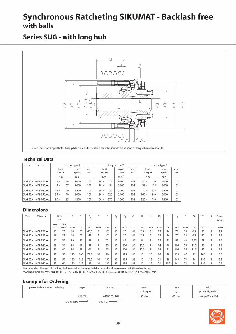
SUG 30.x 4479.125.xxx 10 20 65 63 40,5 5 47 30 70 M4 7,5 7 12 26 72 33 6,5 56 8 1,2
SUG 30.x 4479.125.xxx 19 25 65 63 42 5 47 30 70 M4 7,5 7 12 26 72 33 6,5 56 8 1,2
SUG 40.x 4479.130.xxx 15 30 80 77 57 7 62 40 85 M5 8 8 12 31 88 43 8,75 71 8 1,5
SUG 45.x 4479.140.xxx 19 30 95 88 57 9 75 45 100 M6 10,5 9 14 40 108 55 11,5 85 8 1,8
SUG 45.x 4479.140.xxx 32 40 95 88 64 9 75 45 100 M6 10,5 9 14 31 108 55 11,5 85 8 1,8
SUG 55.x 4479.150.xxx 32 50 110 100 73,5 10 90 55 115 M6 12 10 16 29 124 67 13 100 8 2,0
SUG 65.x 4479.160.xxx 32 50 130 122 73,5 10 100 65 135 M8 12 12 21 29 140 73 14 116 8 2,2
SUG 65.x 4479.160.xxx 55 60 130 122 89 10 100 65 135 M8 12 12 21 45,5 141 73 14 116 8 2,2
D D1 D2 E F F1 F3 G H K K1 L L1 Q Q1 T Z
d*
min. max.mm mm mm mm mm mm mm mm mm mm mm mm mm mm mm mm mm
SUG 30.x 4479.125.xxx 5 - 14 4 000 101 10 - 28 4 000 102 20 - 60 4 000 103
SUG 40.x 4479.130.xxx 9 - 27 3 000 101 18 - 54 3 000 102 38 - 115 3 000 103
SUG 45.x 4479.140.xxx 19 - 60 2 500 101 38 - 125 2 500 102 70 - 255 2 500 103
SUG 55.x 4479.150.xxx 35 - 110 2 000 101 80 - 220 2 000 102 160 - 440 2 000 103
SUG 65.x 4479.160.xxx 80 - 185 1 200 101 160 - 370 1 200 102 320 - 740 1 200 103
SUG 65.1 4479.160. 101 90 Nm 60 mm
d
Synchronous Ratcheting SIKUMAT - Backlash freewith balls
Series SUG - with long hub
Z = number of tapped holes G on pitch circle T · Installation must be shut down as soon as torque limiter responds
type art. no. torque type 1 torque type 2 torque type 3
limit max. end limit max. end limit max. endtorque speed no. torque speed no. torque speed no.
Nm min-1 Nm min-1 Nm min-1
Technical Data
Dimensions
mm
Type Référence Course
active
see p. 60 and 61
torque type end no.
please indicate when ordering: type art. no. preset bore with
limit torque proximity switch
Example for Ordering
bore
Diameter d2 at the end of the long hub is equal to the selected diameter d and serves as an additional centering.*Available bore diameters d: 10, 11, 12, 14, 15, 16, 18, 19, 20, 22, 24, 25, 28, 30, 32, 35, 38, 40, 42, 45, 48, 50, 55 and 60 mm.

40
SUE 30.x 4479.625.xxx 10 20 15 28 70 63 40,5 55 70 7 12 26 47 102 30 30 1,2
SUE 30.x 4479.625.xxx 19 25 15 28 70 63 42 55 70 7 12 26 47 102 30 30 1,2
SUE 40.x 4479.630.xxx 15 30 15 38 85 77 57 65 85 8 12 31 54,5 119,5 35 35 1,5
SUE 45.x 4479.640.xxx 19 30 20 45 100 88 57 80 100 9 14 40 67 146 45 45 1,8
SUE 45.x 4479.640.xxx 32 40 20 45 100 88 64 80 100 9 14 31 67 146 45 45 1,8
SUE 55.x 4479.650.xxx 32 50 25 50 115 100 73,5 95 115 10 16 29 73 159 50 50 2,0
SUE 65.x 4479.660.xxx 32 50 30 55 135 122 73,5 105 135 12 21 29 87 182 56 56 2,2
SUE 65.x 4479.660.xxx 55 60 30 55 135 122 89 105 135 12 21 45,5 87 182 56 56 2,2
A D1 D2 E F3 K K1 L L0 O U Z3d* d3**
min. max. min. max.mm mm mm mm mm mm mm mm mm mm mm mm mm mm mm mm mm
SUE 30.x 4479.625.xxx 5 - 14 4 000 101 10 - 28 4 000 102 20 - 60 4 000 103
SUE 40.x 4479.630.xxx 9 - 27 3 000 101 18 - 54 3 000 102 38 - 115 3 000 103
SUE 45.x 4479.640.xxx 19 - 60 2 500 101 38 - 125 2 500 102 70 - 255 2 500 103
SUE 55.x 4479.650.xxx 35 - 110 2 000 101 80 - 220 2 000 102 160 - 440 2 000 103
SUE 65.x 4479.660.xxx 80 - 185 1 200 101 160 - 370 1 200 102 320 - 740 1 200 103
SUE 30. 1 4479.625. 101 10 Nm 12 mm 20 mm
d d3
Synchronous Ratcheting SIKUMAT - Backlash freewith balls
Series SUE - flexible shaft coupling
Installation must be shut down as soon as torque limiter responds
type art. no. torque type 1 torque type 2 torque type 3
limit max. end limit max. end limit max. endtorque speed no. torque speed no. torque speed no.
Nm min-1 Nm min-1 Nm min-1
Technical Data
Dimensions
mm
Type Référence Course
active
torque type end no.
type
see pages 60 and 61
please indicate when ordering: art. no. preset bore bore with
limit torque proximity switch
Example for Ordering
bore bore
Hub bore diameter d2 is equal to the selected diameter d and serves as an additional centering guide.*Available bore diameters d: 10, 11, 12, 14, 15, 16, 18, 19, 20, 22, 24, 25, 28, 30, 32, 35, 38, 40, 42, 45, 48, 50, 55 and 60 mm.**Available bore diameters d3: 15, 16, 19, 20, 24, 25, 28, 30, 32, 35, 38, 40, 42, 45, 48, 50 and 55 mm.

41
SUL 30.x 4479.425.xxx 10 20 11 20 65 63 40,5 42 53 70 7 12 26 47 95,5 25,5 26,5 1,2
SUL 30.x 4479.425.xxx 19 25 11 20 65 63 42 42 53 70 7 12 26 47 95,5 25,5 26,5 1,2
SUL 40.x 4479.430.xxx 15 30 15 30 80 77 57 58 72 85 8 12 31 56 114,5 33 31 1,5
SUL 45.x 4479.440.xxx 19 40 19 30 97 88 57 58 72 100 9 14 40 67 128 33 31 1,8
SUL 45.x 4479.440.xxx 19 40 24 42 97 88 64 72 89 100 9 14 31 67 150 44,5 45 1,8
SUL 55.x 4479.450.xxx 32 50 24 42 111 100 73,5 72 89 115 10 16 29 73 153,5 44,5 45 2,0
SUL 65.x 4479.460.xxx 32 50 32 42 131 122 73,5 79 118 135 12 21 29 85 163,5 35 29 2,2
SUL 65.x 4479.460.xxx 55 60 45 60 131 122 89 92 118 135 12 21 45,5 86 172,5 44 44 2,2
A D1 D2 D5 E F3 K K1 L L0 O U Z3d* d3**
min. max.mm mm mm mm mm mm mm mm mm mm mm mm mm mm mm mm mm
SUL 30.x 4479.425.xxx 5 - 14 4 000 101 10 - 28 4 000 102 20 - 60 4 000 103
SUL 40.x 4479.430.xxx 9 - 27 3 000 101 18 - 54 3 000 102 38 - 115 3 000 103
SUL 45.x 4479.440.xxx 19 - 60 2 500 101 38 - 125 2 500 102 70 - 255 2 500 103
SUL 55.x 4479.450.xxx 35 - 110 2 000 101 80 - 220 2 000 102 160 - 440 2 000 103
SUL 65.x 4479.460.xxx 80 - 185 1 200 101 160 - 370 1 200 102 320 - 740 1 200 103
SUL 55.3 4479.450. 103 420 Nm 45 mm 35 mm
d d3
Synchronous Ratcheting SIKUMAT - Backlash freewith balls
Series SUL - with torsionally rigid shaft coupling
Installation must be shut down as soon as torque limiter responds
type art. no. torque type 1 torque type 2 torque type 3
limit max. end limit max. end limit max. endtorque speed no. torque speed no. torque speed no.
Nm min-1 Nm min-1 Nm min-1
Technical Data
Dimensions
mm
Type Référence Course
active
torque type end no.
type
see pages 60 and 61
please indicate when ordering: art. no. preset bore bore with
limit torque proximity switch
Example for Ordering
bore bore
Hub bore diameter d2 is equal to the selected diameter d and serves as an additional centering guide.*Available bore diameters d: 10, 11, 12, 14, 15, 16, 18, 19, 20, 22, 24, 25, 28, 30, 32, 35, 38, 40, 42, 45, 48, 50, 55 and 60 mm.**Available bore diameters d3: 15, 16, 19, 20, 24, 25, 28, 30, 32, 35, 38, 40, 42, 45, 48, 50 and 55 mm.
4242
F FF F
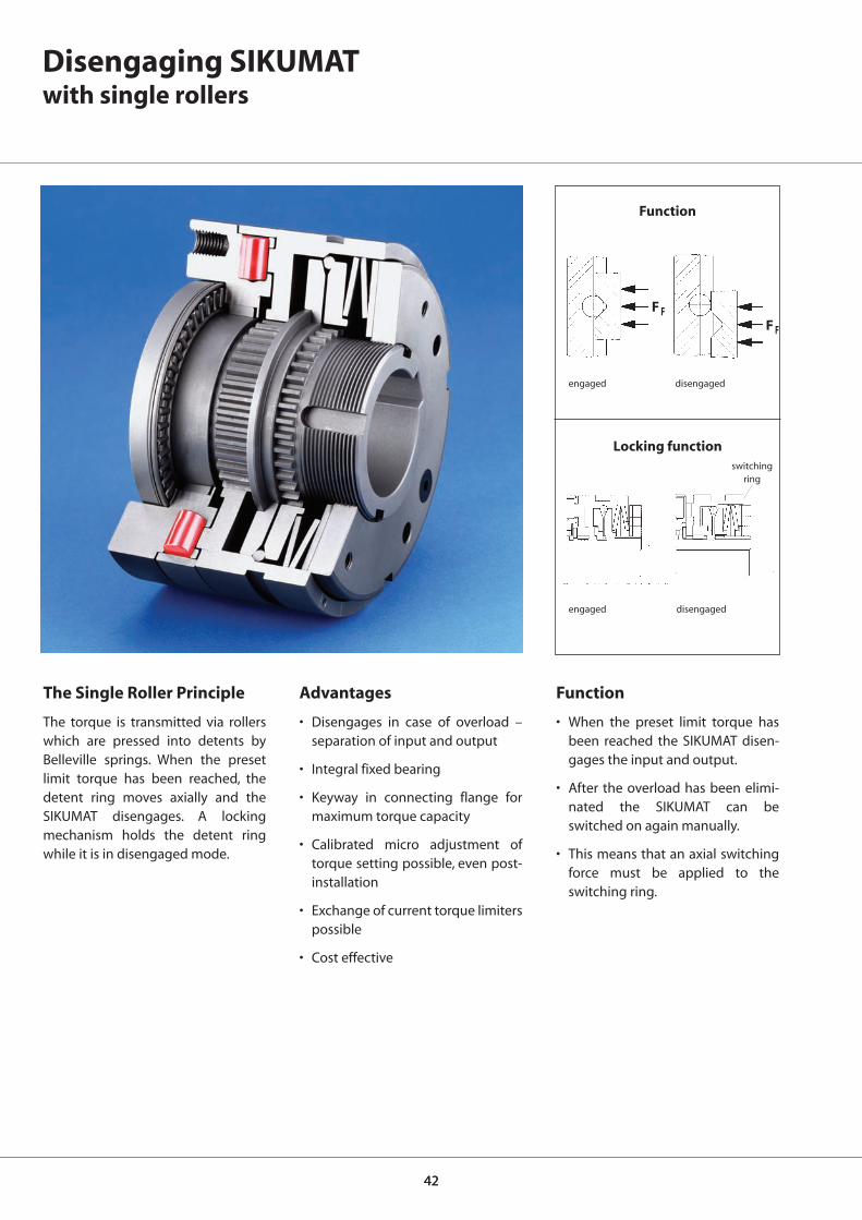
Disengaging SIKUMATwith single rollers
The Single Roller Principle
The torque is transmitted via rollerswhich are pressed into detents byBelleville springs. When the presetlimit torque has been reached, thedetent ring moves axially and theSIKUMAT disengages. A lockingmechanism holds the detent ringwhile it is in disengaged mode.
Advantages
• Disengages in case of overload –separation of input and output
• Integral fixed bearing
• Keyway in connecting flange formaximum torque capacity
• Calibrated micro adjustment oftorque setting possible, even post-installation
• Exchange of current torque limiterspossible
• Cost effective
Function
• When the preset limit torque hasbeen reached the SIKUMAT disen-gages the input and output.
• After the overload has been elimi-nated the SIKUMAT can beswitched on again manually.
• This means that an axial switchingforce must be applied to theswitching ring.
engaged disengaged
Locking function
disengagedengaged
Function
switchingring

4343
Disengaging SIKUMATwith single rollers
Series SR - flange design
Types
Series SRG - with long hub
Series SRR - with short hub and integral roller bearing
Series SRE - with flexible shaft coupling
NotesTorque setting
If requested, the limit torque can beset at the factory. Setting or modifica-tion of the limit torque can also becarried out by the customer. See op-erating instructions for further de-tails.
Proximity switch
The overload can be indicated by anon-contact or a mechanical proxim-ity switch. Further details on pages60 and 61.
With short hub and needle bearingfor narrow connecting parts
With long hub for wide connectingparts. Plain or needle bearing for theconnecting part to be provided bythe customer
Page 44
Page 45
Page 46
Page 47
Speed Control ESC
The RINGSPANN speed control ESC(Electronic Speed Control) monitorsspeed deviations and speed differ-ences safely and also under difficultoperating conditions. See catalogue50.1 for details.
For attaching chain wheels, belt pul-leys, gear wheels etc. Bearing of at-tached component on the shaft to beprovided by the customer.
For flexible connection of two shafts.The flexible parts are oil-proof.

4444
SR 32.x* 4470.020.xxx 7 20 55 41 50 M5 6,5 3 9 13,5 35 38,5 6 3,1 48 38,5 5 6 1,2
SR 40.x 4470.025.xxx 10 25 82 60 72,5 M5 8 6 9 14,5 48 52 6 3,1 70 54 6 6 1,8
SR 55.x 4470.035.xxx 14 35 100 78 90,5 M6 10 6 9 15 56 61 8 3,6 89 70 6 6 2,0
SR 65.x 4470.045.xxx 18 45 120 90,5 112 M8 12 8,5 10 22,5 72 78 10 4,1 105 84 6 6 2,2
SR 80.x 4470.055.xxx 24 55 146 105 140 M10 15 11 9 25 93,5 100 12 4,1 125 108 7 6 2,5
SR 90.x 4470.065.xxx 30 701) 176 120,5 170 M12 17 12 9 30 107 113,5 14 4,6 155 129 10 6 3,0
D F F3 G H J K K1 L L0 N N1 T X Y Z
d
min. max.mm mm mm mm mm mm mm mm mm mm mm mm mm mm mm mm
SR 32.x 4470.020.xxx 5 - 10 6 000 601 10 - 20 6 000 602 20 - 40 6 000 603
SR 40.x 4470.025.xxx 12 - 25 5 000 601 25 - 50 5 000 602 50 - 100 5 000 603
SR 55.x 4470.035.xxx 25 - 50 4 000 601 50 - 100 4 000 602 100 - 200 4 000 603
SR 65.x 4470.045.xxx 50 - 100 3 500 601 100 - 200 3 500 602 200 - 450 3 500 603
SR 80.x 4470.055.xxx 100 - 200 3 000 601 200 - 400 3 000 602 400 - 800 3 000 603
SR 90.x 4470.065.xxx 170 - 450 2 300 601 350 - 900 2 300 602 600 - 1 800 2 300 603
SR 40. 2 4470.025. 602 30 Nm 21 mm
d
Z = number of tapped holes G on pitch circle T
Disengaging SIKUMATwith single rollers
Series SR - flange design
type art. no. torque type 1 torque type 2 torque type 3
limit max. end limit max. end limit max. endtorque speed no. torque speed no. torque speed no.
Nm min-1 Nm min-1 Nm min-1
Technical Data
Dimensions
mm
Type Référence Course
active
see p. 60 and 61
torque type end no.
please indicate when ordering: type art. no. preset bore with
limit torque proximity switch
Example for Ordering
bore
Keyway as per DIN 6885, page 1 · Tolerance of keyway width JS91)Keyway as per DIN 6885, page 3 · Tolerance of keyway width JS9* SR 32.x available on request
keyway width N
1 x between 2 tapped holes
4545
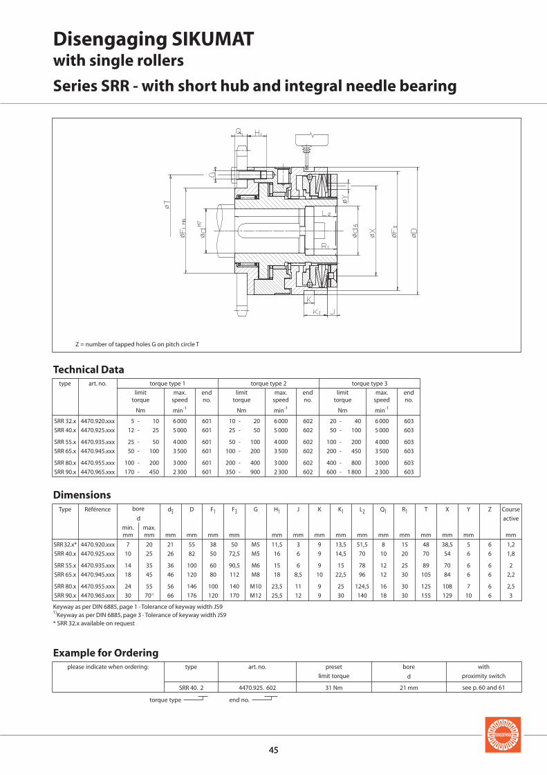
SRR 32.x* 4470.920.xxx 7 20 21 55 38 50 M5 11,5 3 9 13,5 51,5 8 15 48 38,5 5 6 1,2
SRR 40.x 4470.925.xxx 10 25 26 82 50 72,5 M5 16 6 9 14,5 70 10 20 70 54 6 6 1,8
SRR 55.x 4470.935.xxx 14 35 36 100 60 90,5 M6 15 6 9 15 78 12 25 89 70 6 6 2
SRR 65.x 4470.945.xxx 18 45 46 120 80 112 M8 18 8,5 10 22,5 96 12 30 105 84 6 6 2,2
SRR 80.x 4470.955.xxx 24 55 56 146 100 140 M10 23,5 11 9 25 124,5 16 30 125 108 7 6 2,5
SRR 90.x 4470.965.xxx 30 701) 66 176 120 170 M12 25,5 12 9 30 140 18 30 155 129 10 6 3
d5 D F1 F3 G H1 J K K1 L2 Q1 R1 T X Y Z
d
min. max.mm mm mm mm mm mm mm mm mm mm mm mm mm mm mm mm
SRR 32.x 4470.920.xxx 5 - 10 6 000 601 10 - 20 6 000 602 20 - 40 6 000 603
SRR 40.x 4470.925.xxx 12 - 25 5 000 601 25 - 50 5 000 602 50 - 100 5 000 603
SRR 55.x 4470.935.xxx 25 - 50 4 000 601 50 - 100 4 000 602 100 - 200 4 000 603
SRR 65.x 4470.945.xxx 50 - 100 3 500 601 100 - 200 3 500 602 200 - 450 3 500 603
SRR 80.x 4470.955.xxx 100 - 200 3 000 601 200 - 400 3 000 602 400 - 800 3 000 603
SRR 90.x 4470.965.xxx 170 - 450 2 300 601 350 - 900 2 300 602 600 - 1 800 2 300 603
SRR 40. 2 4470.925. 602 31 Nm 21 mm
d
Disengaging SIKUMATwith single rollers
Series SRR - with short hub and integral needle bearing
Z = number of tapped holes G on pitch circle T
type art. no. torque type 1 torque type 2 torque type 3
limit max. end limit max. end limit max. endtorque speed no. torque speed no. torque speed no.
Nm min-1 Nm min-1 Nm min-1
Technical Data
Dimensions
mm
Type Référence Course
active
see p. 60 and 61
torque type end no.
please indicate when ordering: type art. no. preset bore with
limit torque proximity switch
Example for Ordering
bore
Keyway as per DIN 6885, page 1 · Tolerance of keyway width JS91)Keyway as per DIN 6885, page 3 · Tolerance of keyway width JS9* SRR 32.x available on request
4646
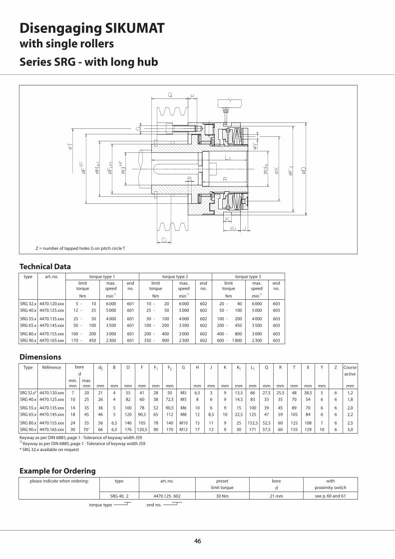
SRG 32.x* 4470.120.xxx 7 20 21 4 55 41 28 50 M5 6,5 3 9 13,5 66 27,5 25,5 48 38,5 5 6 1,2
SRG 40.x 4470.125.xxx 10 25 26 4 82 60 38 72,5 M5 8 6 9 14,5 83 33 35 70 54 6 6 1,8
SRG 55.x 4470.135.xxx 14 35 36 5 100 78 52 90,5 M6 10 6 9 15 100 39 45 89 70 6 6 2,0
SRG 65.x 4470.145.xxx 18 45 46 5 120 90,5 65 112 M8 12 8,5 10 22,5 125 47 59 105 84 6 6 2,2
SRG 80.x 4470.155.xxx 24 55 56 6,5 146 105 78 140 M10 15 11 9 25 152,5 52,5 60 125 108 7 6 2,5
SRG 90.x 4470.165.xxx 30 701) 66 6,5 176 120,5 90 170 M12 17 12 9 30 171 57,5 60 155 129 10 6 3,0
SRG 32.x 4470.120.xxx 5 - 10 6 000 601 10 - 20 6 000 602 20 - 40 6 000 603
SRG 40.x 4470.125.xxx 12 - 25 5 000 601 25 - 50 5 000 602 50 - 100 5 000 603
SRG 55.x 4470.135.xxx 25 - 50 4 000 601 50 - 100 4 000 602 100 - 200 4 000 603
SRG 65.x 4470.145.xxx 50 - 100 3 500 601 100 - 200 3 500 602 200 - 450 3 500 603
SRG 80.x 4470.155.xxx 100 - 200 3 000 601 200 - 400 3 000 602 400 - 800 3 000 603
SRG 90.x 4470.165.xxx 170 - 450 2 300 601 350 - 900 2 300 602 600 - 1 800 2 300 603
SRG 40. 2 4470.125. 602 30 Nm 21 mm
d5 B D F F1 F3 G H J K K1 L1 Q R T X Y Z
d
min. max.mm mm mm mm mm mm mm mm mm mm mm mm mm mm mm mm mm mm
d
Disengaging SIKUMATwith single rollers
Series SRG - with long hub
Z = number of tapped holes G on pitch circle T
type art. no. torque type 1 torque type 2 torque type 3
limit max. end limit max. end limit max. endtorque speed no. torque speed no. torque speed no.
Nm min-1 Nm min-1 Nm min-1
Technical Data
Dimensions
mm
Type Référence Course
active
see p. 60 and 61
torque type end no.
please indicate when ordering: type art. no. preset bore with
limit torque proximity switch
Example for Ordering
bore
Keyway as per DIN 6885, page 1 · Tolerance of keyway width JS91) Keyway as per DIN 6885, page 1 · Tolerance of keyway width JS9* SRG 32.x available on request
4747
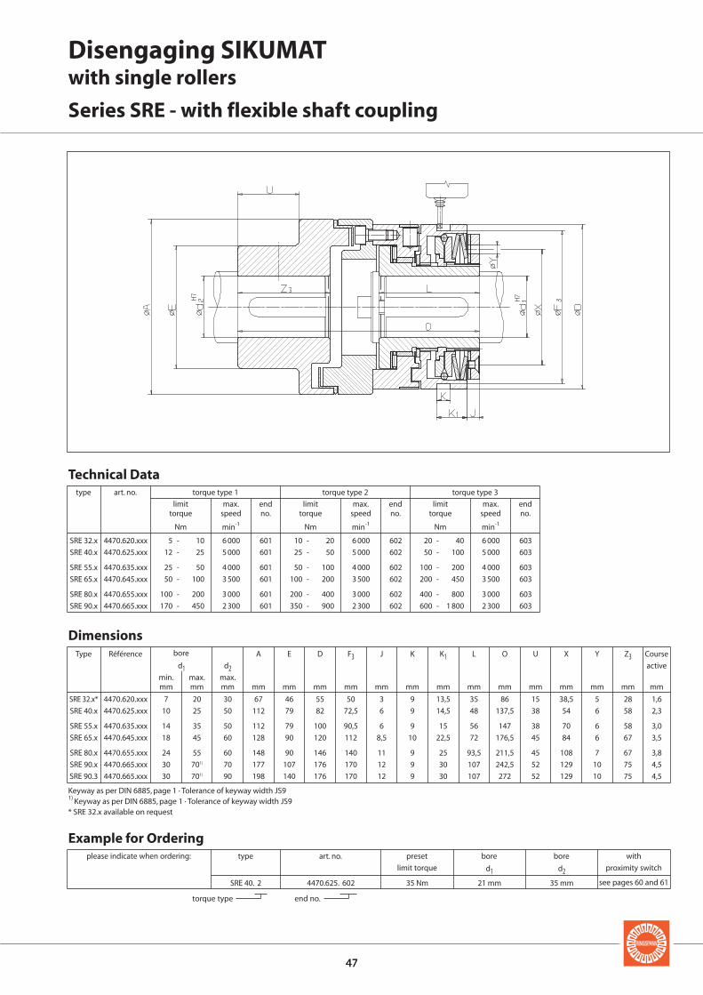
SRE 32.x* 4470.620.xxx 7 20 30 67 46 55 50 3 9 13,5 35 86 15 38,5 5 28 1,6
SRE 40.x 4470.625.xxx 10 25 50 112 79 82 72,5 6 9 14,5 48 137,5 38 54 6 58 2,3
SRE 55.x 4470.635.xxx 14 35 50 112 79 100 90,5 6 9 15 56 147 38 70 6 58 3,0
SRE 65.x 4470.645.xxx 18 45 60 128 90 120 112 8,5 10 22,5 72 176,5 45 84 6 67 3,5
SRE 80.x 4470.655.xxx 24 55 60 148 90 146 140 11 9 25 93,5 211,5 45 108 7 67 3,8
SRE 90.x 4470.665.xxx 30 701) 70 177 107 176 170 12 9 30 107 242,5 52 129 10 75 4,5
SRE 90.3 4470.665.xxx 30 701) 90 198 140 176 170 12 9 30 107 272 52 129 10 75 4,5
SRE 32.x 4470.620.xxx 5 - 10 6 000 601 10 - 20 6 000 602 20 - 40 6 000 603
SRE 40.x 4470.625.xxx 12 - 25 5 000 601 25 - 50 5 000 602 50 - 100 5 000 603
SRE 55.x 4470.635.xxx 25 - 50 4 000 601 50 - 100 4 000 602 100 - 200 4 000 603
SRE 65.x 4470.645.xxx 50 - 100 3 500 601 100 - 200 3 500 602 200 - 450 3 500 603
SRE 80.x 4470.655.xxx 100 - 200 3 000 601 200 - 400 3 000 602 400 - 800 3 000 603
SRE 90.x 4470.665.xxx 170 - 450 2 300 601 350 - 900 2 300 602 600 - 1 800 2 300 603
A E D F3 J K K1 L O U X Y Z3d1 d2
min. max. max.mm mm mm mm mm mm mm mm mm mm mm mm mm mm mm mm
SRE 40. 2 4470.625. 602 35 Nm 21 mm 35 mm
d1 d2
Disengaging SIKUMATwith single rollers
Series SRE - with flexible shaft coupling
type art. no. torque type 1 torque type 2 torque type 3
limit max. end limit max. end limit max. endtorque speed no. torque speed no. torque speed no.
Nm min-1 Nm min-1 Nm min-1
Technical Data
Dimensions
mm
Type Référence Course
active
torque type end no.
type
see pages 60 and 61
please indicate when ordering: art. no. preset bore bore with
limit torque proximity switch
Example for Ordering
bore
Keyway as per DIN 6885, page 1 · Tolerance of keyway width JS91) Keyway as per DIN 6885, page 1 · Tolerance of keyway width JS9* SRE 32.x available on request

4848
Synchronous Disengaging SIKUMATwith double rollers
Advantages
• High degree of consistency of limittorque over the duration of opera-tion through double roller princi-ple
• Switching off in case of overload –separation of input and output
• Synchronous re-engagement after360°
• Torques up to 10 000 Nm
• For shaft diameters up to 125 mm
• Protection against unauthorisedadjustment of the limit torque
engaged
disengaged
engaged
disengaged
Function
Locking mechanism
switchingring
Function
• When the preset limit torque hasbeen reached the SIKUMAT effectsa separation of input and outputby means of a locking mechanismwith integral bearings.
• Following elimination of the over-load manual synchronous re-en-gagement of the SIKUMAT to thestarting position after 360°.
• This requires an axial switchingforce to be applied to the switch-ing ring.
The Double Roller Principle
The torque is transmitted via six pairsof rollers which are pressed by coilsprings into detents. When the presetlimit torque has been reached, therollers move against the spring forceup the sloping surface and disen-gage. This characteristic combinedwith the particular geometry of thedetents provide a high degree ofconsistency to the limit torque of theSIKUMAT over the duration of the op-erating period. Re-engagement is ef-fected synchronously after 360º dueto the asymmetrical division of thedetents.

4949
Synchronous Disengaging SIKUMATwith double rollers
Series SB - flange design
Types
Series SBG - with long hub
Series SBL - with torsionally rigid shaft coupling
Series SBE - with flexible shaft coupling
NotesProximity switch
The overload can be indicated by anon-contact or a mechanical proxim-ity switch. Further details on pages60 and 61.
With long hub for wide connectingparts. Delivery includes plain bearing
Page 50
Page 51
Page 52
Page 53
Speed Control ESC
The RINGSPANN speed control ESC(Electronic Speed Control) monitorsspeed deviations and speed differ-ences safely and also under difficultoperating conditions. See catalogue50.1 for details.
For attaching chain wheels, belt pul-leys, gear wheels etc. Bearing of at-tached component on the shaft to beprovided by the customer.
For flexible connection of two shafts.The flexible parts are oil-proof.
For torsionally rigid connection oftwo shafts. Can accommodate largeradial and angular displacements.
Torque setting
The limit torque is normally set at thefactory. Setting or modification of thelimit torque can also be carried outby the customer but no unautho-rised adjustment can be carried outby the machine operator. See operat-ing instructions for further details.
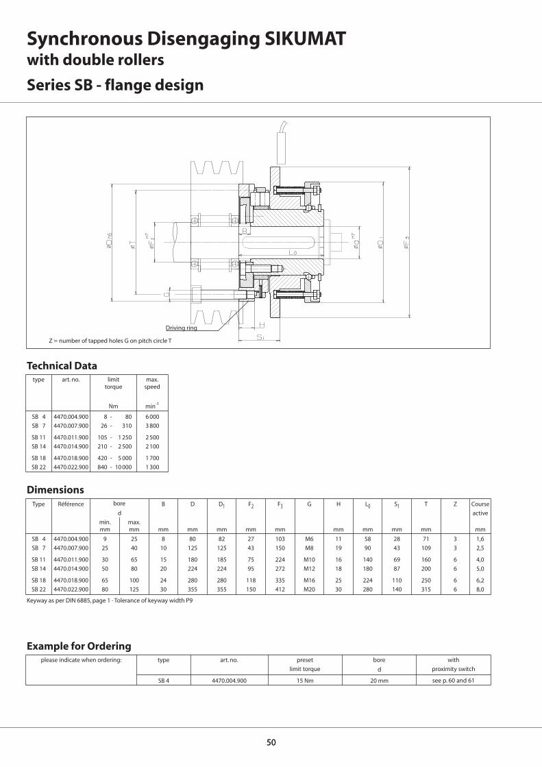
5050
SB 4 4470.004.900 9 25 8 80 82 27 103 M6 11 58 28 71 3 1,6
SB 7 4470.007.900 25 40 10 125 125 43 150 M8 19 90 43 109 3 2,5
SB 11 4470.011.900 30 65 15 180 185 75 224 M10 16 140 69 160 6 4,0
SB 14 4470.014.900 50 80 20 224 224 95 272 M12 18 180 87 200 6 5,0
SB 18 4470.018.900 65 100 24 280 280 118 335 M16 25 224 110 250 6 6,2
SB 22 4470.022.900 80 125 30 355 355 150 412 M20 30 280 140 315 6 8,0
B D D1 F2 F3 G H L0 S1 T Z
d
min. max.mm mm mm mm mm mm mm mm mm mm mm
SB 4 4470.004.900 8 - 80 6 000
SB 7 4470.007.900 26 - 310 3 800
SB 11 4470.011.900 105 - 1 250 2 500
SB 14 4470.014.900 210 - 2 500 2 100
SB 18 4470.018.900 420 - 5 000 1 700
SB 22 4470.022.900 840 - 10 000 1 300
SB 4 4470.004.900 15 Nm 20 mm
d
Driving ring
Synchronous Disengaging SIKUMATwith double rollers
Series SB - flange design
Z = number of tapped holes G on pitch circle T
bore
type art. no. limit max.torque speed
Nm min-1
Technical Data
Dimensions
mm
Type Référence Course
active
Keyway as per DIN 6885, page 1 · Tolerance of keyway width P9
see p. 60 and 61
please indicate when ordering: type art. no. preset bore with
limit torque proximity switch
Example for Ordering

5151
SBG 4 4470.104.900 9 25 25 80 82 103 M6 11 103 55 32 24 71 3 39 1,6
SBG 7 4470.107.900 25 40 40 125 125 150 M8 19 155 80 46 38 109 3 55 2,5
SBG 11 4470.111.900 40 65 63 180 185 224 M10 16 250 120 75 61 160 6 87 4,0
SBG 14 4470.114.900 50 80 80 224 224 272 M12 18 275 155 95 87 200 6 109 5,0
C D D1 F3 G H L1 M Q S1 T Z Z1d1
min. max.mm mm mm mm mm mm mm mm mm mm mm mm mm
SBG 4 4470.104.900 8 - 80 6 000
SBG 7 4470.107.900 26 - 310 3 800
SBG 11 4470.111.900 105 - 1 250 2 500
SBG 14 4470.114.900 210 - 2 500 2 100
SBG 4 4470.104.900 15 Nm 18 mm
d1
Synchronous Disengaging SIKUMATwith double rollers
Series SBG - with long hub
Z = number of tapped holes G on pitch circle T
bore
type art. no. limit max.torque speed
Nm min-1
Technical Data
Dimensions
mm
Type Référence Course
active
Bore d2 is 0,2…0,5 mm larger than d1 for sizes 4 – 7Bore d2 is 0,5…1,0 mm larger than d1 for sizes 11 – 14Keyway as per DIN 6885, page 1 · Tolerance of keyway width P9
see p. 60 and 61
please indicate when ordering: type art. no. preset bore with
limit torque proximity switch
Example for Ordering
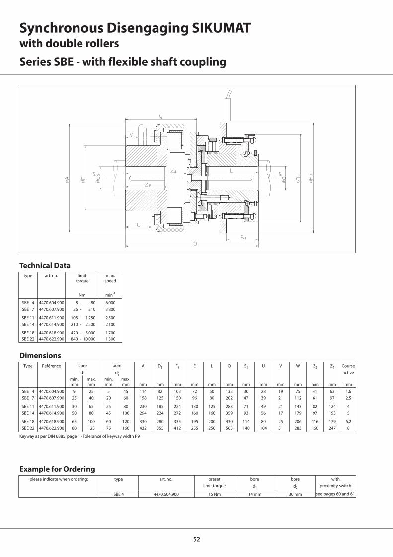
5252
SBE 4 4470.604.900 9 25 5 45 114 82 103 72 50 133 30 28 19 75 41 63 1,6
SBE 7 4470.607.900 25 40 20 60 158 125 150 96 80 202 47 39 21 112 61 97 2,5
SBE 11 4470.611.900 30 65 25 80 230 185 224 130 125 283 71 49 21 143 82 124 4
SBE 14 4470.614.900 50 80 45 100 294 224 272 160 160 359 93 56 17 179 97 153 5
SBE 18 4470.618.900 65 100 60 120 330 280 335 195 200 430 114 80 25 206 116 179 6,2
SBE 22 4470.622.900 80 125 75 160 432 355 412 255 250 563 140 104 31 283 160 247 8
A D1 F3 E L O S1 U V W Z3 Z4d1 d2
min. max. min. max.mm mm mm mm mm mm mm mm mm mm mm mm mm mm mm mm
SBE 4 4470.604.900 8 - 80 6 000
SBE 7 4470.607.900 26 - 310 3 800
SBE 11 4470.611.900 105 - 1 250 2 500
SBE 14 4470.614.900 210 - 2 500 2 100
SBE 18 4470.618.900 420 - 5 000 1 700
SBE 22 4470.622.900 840 - 10 000 1 300
SBE 4 4470.604.900 15 Nm 14 mm 30 mm
d1 d2
Synchronous Disengaging SIKUMATwith double rollers
Series SBE - with flexible shaft coupling
bore bore
type art. no. limit max.torque speed
Nm min-1
Technical Data
Dimensions
mm
Type Référence Course
active
Keyway as per DIN 6885, page 1 · Tolerance of keyway width P9
type
see pages 60 and 61
please indicate when ordering: art. no. preset bore bore with
limit torque proximity switch
Example for Ordering
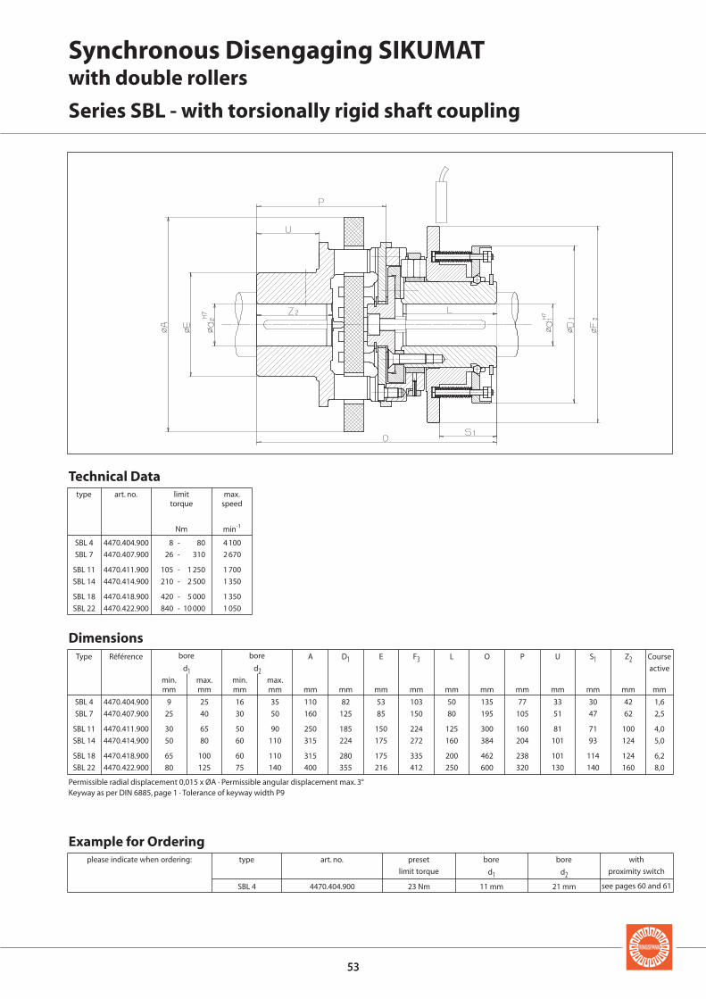
5353
SBL 4 4470.404.900 23 Nm 11 mm 21 mm
d1 d2
SBL 4 4470.404.900 9 25 16 35 110 82 53 103 50 135 77 33 30 42 1,6
SBL 7 4470.407.900 25 40 30 50 160 125 85 150 80 195 105 51 47 62 2,5
SBL 11 4470.411.900 30 65 50 90 250 185 150 224 125 300 160 81 71 100 4,0
SBL 14 4470.414.900 50 80 60 110 315 224 175 272 160 384 204 101 93 124 5,0
SBL 18 4470.418.900 65 100 60 110 315 280 175 335 200 462 238 101 114 124 6,2
SBL 22 4470.422.900 80 125 75 140 400 355 216 412 250 600 320 130 140 160 8,0
A D1 E F3 L O P U S1 Z2d1 d2
min. max. min. max.mm mm mm mm mm mm mm mm mm mm mm mm mm mm
SBL 4 4470.404.900 8 - 80 4 100
SBL 7 4470.407.900 26 - 310 2 670
SBL 11 4470.411.900 105 - 1 250 1 700
SBL 14 4470.414.900 210 - 2 500 1 350
SBL 18 4470.418.900 420 - 5 000 1 350
SBL 22 4470.422.900 840 - 10 000 1 050
Synchronous Disengaging SIKUMATwith double rollers
Series SBL - with torsionally rigid shaft coupling
bore bore
Permissible radial displacement 0,015 x ØA · Permissible angular displacement max. 3°Keyway as per DIN 6885, page 1 · Tolerance of keyway width P9
type art. no. limit max.torque speed
Nm min-1
Technical Data
Dimensions
mm
Type Référence Course
active
type
see pages 60 and 61
please indicate when ordering: art. no. preset bore bore with
limit torque proximity switch
Example for Ordering

5454
F FF F
Non-disengaging SIKUMATwith single rollers
engaged overloaded
Overload signal
overloadednormal operation
Function
The Single Roller Principle
The torque is transmitted via rollerswhich are pressed by Bellevillesprings into detents. When the presetlimit torque has been reached, thedetent ring is displaced but is pre-vented by its particular design fromdisengaging completely. There istherefore no disengaging of inputand output.
Advantages
• Output is fully driven even in caseof overload
• Integral fixed bearing
• Driving keyway in the connectingflange for maximum torque capac-ity.
• Calibrated micro adjustment oftorque setting possible, even post-installation
• Exchange of current torque limiterspossible
• Cost effective
Function
• When the preset limit torque hasbeen reached, a limit sensor indi-cates the overload.
• There is no interruption of torquetransmission between drive and out-put.

5555
Non-disengaging SIKUMATwith single rollers
Series SL - flange design
Types
Series SLG - with long hub
Series SLR - with short hub and integral needle bearing
Series SLE - with flexible shaft coupling
Notes
With short hub supported by needlebearings, for connecting narrowcomponents
With long hub for connecting widecomponents. Bearings of the at-tached component to be providedby the customer
Page 56
Page 57
Page 58
Page 59
Torque setting
The limit torque can be set at the fac-tory on request. Setting or modifica-tion of the limit torque can also becarried out by the customer. See op-erating instructions for further de-tails.
Proximity switch
The overload can be indicated by anon-contact or a mechanical proxim-ity switch. Further details on pages60 and 61.
Speed Control ESC
The RINGSPANN speed control ESC(Electronic Speed Control) monitorsspeed deviations and speed differ-ences safely and also under difficultoperating conditions. See catalogue50.1 for details.
For attaching chain wheels, belt pul-leys, gear wheels etc. Bearing of at-tached component on the shaft to beprovided by the customer.
For flexible connection of two shafts.The flexible parts are oil-proof.

5656
SL 32.x 4470.020.xxx 7 20 55 41 50 M5 6,5 3 9 13,5 35 38,5 6 3,1 48 38,5 5 6 0,6
SL 40.x 4470.025.xxx 10 25 82 60 72,5 M5 8 6 9 14,5 48 52 6 3,1 70 54 6 6 0,8
SL 55.x 4470.035.xxx 14 35 100 78 90,5 M6 10 6 9 15 56 61 8 3,6 89 70 6 6 1,1
SL 65.x 4470.045.xxx 18 45 120 90,5 112 M8 12 8,5 10 22,5 72 78 10 4,1 105 84 6 6 1,2
SL 80.x 4470.055.xxx 24 55 146 105 140 M10 15 11 9 25 93,5 100 12 4,1 125 108 7 6 1,2
SL 90.x 4470.065.xxx 30 701) 176 120,5 170 M12 17 12 9 30 107 113,5 14 4,6 155 129 10 6 1,6
D F F3 G H J K K1 L L0 N N1 T X Y Z
d
min. max.mm mm mm mm mm mm mm mm mm mm mm mm mm mm mm mm
SL 32.x 4470.020.xxx 5 - 10 4 000 701 10 - 20 4 000 702 20 - 40 3 000 703
SL 40.x 4470.025.xxx 12 - 25 3 900 701 25 - 50 3 900 702 50 - 100 2 900 703
SL 55.x 4470.035.xxx 25 - 50 3 300 701 50 - 100 3 300 702 100 - 200 2 400 703
SL 65.x 4470.045.xxx 50 - 100 2 800 701 100 - 200 2 800 702 200 - 450 2 000 703
SL 80.x 4470.055.xxx 100 - 200 2 300 701 200 - 400 2 300 702 400 - 800 1 600 703
SL 90.x 4470.065.xxx 170 - 450 1 800 701 350 - 900 1 800 702 600 - 1 800 1 400 703
SL 32. 1 4470.020. 701 9 Nm 14 mm
d
keyway width N
1 x between 2 tapped holes
Non-disengaging SIKUMATwith single rollers
Series SL - flange design
Z = number of tapped holes G on pitch circle T
type art. no. torque type 1 torque type 2 torque type 3
limit max. end limit max. end limit max. endtorque speed no. torque speed no. torque speed no.
Nm min-1 Nm min-1 Nm min-1
Technical Data
Dimensions
mm
Type Référence Course
active
see p. 60 and 61
torque type end no.
please indicate when ordering: type art. no. preset bore with
limit torque proximity switch
Example for Ordering
bore
Keyway as per DIN 6885, page 1 · Tolerance of keyway width JS91)Keyway as per DIN 6885, page 3 · Tolerance of keyway width JS9

5757
SLR 32.x 4470.920.xxx 7 20 21 55 38 50 M5 11,5 3 9 13,5 51,5 8 15 48 38,5 5 6 0,6
SLR 40.x 4470.925.xxx 10 25 26 82 50 72,5 M5 16 6 9 14,5 70 10 20 70 54 6 6 0,8
SLR 55.x 4470.935.xxx 14 35 36 100 60 90,5 M6 15 6 9 15 78 12 25 89 70 6 6 1,1
SLR 65.x 4470.945.xxx 18 45 46 120 80 112 M8 18 8,5 10 22,5 96 12 30 105 84 6 6 1,2
SLR 80.x 4470.955.xxx 24 55 56 146 100 140 M10 23,5 11 9 25 124,5 16 30 125 108 7 6 1,2
SLR 90.x 4470.965.xxx 30 701) 66 176 120 170 M12 25,5 12 9 30 140 18 30 155 129 10 6 1,6
d5 D F1 F3 G H1 J K K1 L2 Q1 R1 T X Y Z
d
min. max.mm mm mm mm mm mm mm mm mm mm mm mm mm mm mm mm
SLR 32.x 4470.920.xxx 5 - 10 4 000 701 10 - 20 4 000 702 20 - 40 3 000 703
SLR 40.x 4470.925.xxx 12 - 25 3 900 701 25 - 50 3 900 702 50 - 100 2 900 703
SLR 55.x 4470.935.xxx 25 - 50 3 300 701 50 - 100 3 300 702 100 - 200 2 400 703
SLR 65.x 4470.945.xxx 50 - 100 2 800 701 100 - 200 2 800 702 200 - 450 2 000 703
SLR 80.x 4470.955.xxx 100 - 200 2 300 701 200 - 400 2 300 702 400 - 800 1 600 703
SLR 90.x 4470.965.xxx 170 - 450 1 800 701 350 - 900 1 800 702 600 - 1 800 1 400 703
SLR 32. 1 4470.920. 701 9 Nm 18 mm
d
Non-disengaging SIKUMATwith single rollers
Series SLR - with short hub and integral needle bearing
Z = number of tapped holes G on pitch circle T
type art. no. torque type 1 torque type 2 torque type 3
limit max. end limit max. end limit max. endtorque speed no. torque speed no. torque speed no.
Nm min-1 Nm min-1 Nm min-1
Technical Data
Dimensions
mm
Type Référence Course
active
see p. 60 and 61
torque type end no.
please indicate when ordering: type art. no. preset bore with
limit torque proximity switch
Example for Ordering
bore
Keyway as per DIN 6885, page 1 · Tolerance of keyway width JS91)Keyway as per DIN 6885, page 3 · Tolerance of keyway width JS9

5858
SLG 32.x 4470.120.xxx 7 20 21 4 55 41 28 50 M5 6,5 3 9 13,5 66 27,5 25,5 48 38,5 5 6 0,6
SLG 40.x 4470.125.xxx 10 25 26 4 82 60 38 72,5 M5 8 6 9 14,5 83 33 35 70 54 6 6 0,8
SLG 55.x 4470.135.xxx 14 35 36 5 100 78 52 90,5 M6 10 6 9 15 100 39 45 89 70 6 6 1,1
SLG 65.x 4470.145.xxx 18 45 46 5 120 90,5 65 112 M8 12 8,5 10 22,5 125 47 59 105 84 6 6 1,2
SLG 80.x 4470.155.xxx 24 55 56 6,5 146 105 78 140 M10 15 11 9 25 152,5 52,5 60 125 108 7 6 1,2
SLG 90.x 4470.165.xxx 30 701) 66 6,5 176 120,5 90 170 M12 17 12 9 30 171 57,5 60 155 129 10 6 1,6
SLG 32.x 4470.120.xxx 5 - 10 4 000 701 10 - 20 4 000 702 20 - 40 3 000 703
SLG 40.x 4470.125.xxx 12 - 25 3 900 701 25 - 50 3 900 702 50 - 100 2 900 703
SLG 55.x 4470.135.xxx 25 - 50 3 300 701 50 - 100 3 300 702 100 - 200 2 400 703
SLG 65.x 4470.145.xxx 50 - 100 2 800 701 100 - 200 2 800 702 200 - 450 2 000 703
SLG 80.x 4470.155.xxx 100 - 200 2 300 701 200 - 400 2 300 702 400 - 800 1 600 703
SLG 90.x 4470.165.xxx 170 - 450 1 800 701 350 - 900 1 800 702 600 - 1 800 1 400 703
SLG 32. 1 4470.120. 701 9 Nm 14 mm
d5 B D F F1 F3 G H J K K1 L1 Q R T X Y Z
d
min. max.mm mm mm mm mm mm mm mm mm mm mm mm mm mm mm mm mm mm
d
Z = number of tapped holes G on pitch circle T
Non-disengaging SIKUMATwith single rollers
Series SLG - with long hub
type art. no. torque type 1 torque type 2 torque type 3
limit max. end limit max. end limit max. endtorque speed no. torque speed no. torque speed no.
Nm min-1 Nm min-1 Nm min-1
Technical Data
Dimensions
mm
Type Référence Course
active
see p. 60 and 61
torque type end no.
please indicate when ordering: type art. no. preset bore with
limit torque proximity switch
Example for Ordering
bore
Keyway as per DIN 6885, page 1 · Tolerance of keyway width JS91)Keyway as per DIN 6885, page 3 · Tolerance of keyway width JS9

5959
SLE 32.x 4470.620.xxx 7 20 30 67 46 55 50 3 9 13,5 35 86 15 38,5 5 28 0,6
SLE 40.x 4470.625.xxx 10 25 50 112 79 82 72,5 6 9 14,5 48 137,5 38 54 6 58 0,8
SLE 55.x 4470.635.xxx 14 35 50 112 79 100 90,5 6 9 15 56 147 38 70 6 58 1,1
SLE 65.x 4470.645.xxx 18 45 60 128 90 120 112 8,5 10 22,5 72 176,5 45 84 6 67 1,2
SLE 80.x 4470.655.xxx 24 55 60 148 90 146 140 11 9 25 93,5 211,5 45 108 7 67 1,2
SLE 90.x 4470.665.xxx 30 701) 70 177 107 176 170 12 9 30 107 242,5 52 129 10 75 1,6
SLE 90.3 4470.665.xxx 30 701) 90 198 140 176 170 12 9 30 107 272 52 129 10 75 3,0
SLE 32.x 4470.620.xxx 5 - 10 4 000 701 10 - 20 4 000 702 20 - 40 3 000 703
SLE 40.x 4470.625.xxx 12 - 25 3 900 701 25 - 50 3 900 702 50 - 100 2 900 703
SLE 55.x 4470.635.xxx 25 - 50 3 300 701 50 - 100 3 300 702 100 - 200 2 400 703
SLE 65.x 4470.645.xxx 50 - 100 2 800 701 100 - 200 2 800 702 200 - 450 2 000 703
SLE 80.x 4470.655.xxx 100 - 200 2 300 701 200 - 400 2 300 702 400 - 800 1 600 703
SLE 90.x 4470.665.xxx 170 - 450 1 800 701 350 - 900 1 800 702 600 - 1 800 1 400 703
A E D F3 J K K1 L O U X Y Z3d1 d2
min. max. max.mm mm mm mm mm mm mm mm mm mm mm mm mm mm mm mm
SLE 32. 1 4470.620. 701 8 Nm 11 mm 21 mm
d1 d2
Non-disengaging SIKUMATwith single rollers
Series SLE - with flexible shaft coupling
type art. no. torque type 1 torque type 2 torque type 3
limit max. end limit max. end limit max. endtorque speed no. torque speed no. torque speed no.
Nm min-1 Nm min-1 Nm min-1
Technical Data
Dimensions
mm
Type Référence Course
active
torque type end no.
type
see pages 60 and 61
please indicate when ordering: art. no. preset bore bore with
limit torque proximity switch
Example for Ordering
bore
Keyway as per DIN 6885, page 1 · Tolerance of keyway width JS91)Keyway as per DIN 6885, page 3 · Tolerance of keyway width JS9

6060
Non-contact SIKUMAT Proximity Switch
It is possible with SIKUMAT TorqueLimiters to utilise the axial move-ment during an overload occurrenceto actuate a proximity switch so thatwhen the preset limit torque is exceeded, the drive can be switchedoff electrically and/or a signal can betriggered.
Switching off the drive in case ofoverload is essential for all ratchetingtype SIKUMAT Torque Limiters in order to prevent ratcheting over prolonged periods and possiblewear.
The engagement travel of the SIKUMAT Torque Limiters can befound in the respective tables.
Non-contact proximity switches operate free from wear and guarantee faster response times than mechanical limit sensors.
Function
normal operation overload
AC
Article number:
Operating voltage:
Electronic contact
Max. switching distance:
Switching frequency:
Ambient temperature:
Intermittent switch-ing-on load at 220 V:
Min. required nominalload at 220 V:
Permissible nominalload at 200 V:
Repeat accuracy:
Connecting cablelength:
3504.000.073
220 V
5 mm
25 Hz
-25° ... +70° C
3 A
5 mA
200 mA
≤ 1 %
2 m
DC
Article number:
Operating voltage:
NPN output
Max. switchingdistance:
Max. switchingcurrent:
Switching frequency:
Mounting oscillation:
Output:
Ambient temperature:
Connecting cablelength:
3504.000.072
24 V ± 25 %
2 mm
200 mA
500 Hz
≤ 30 %
= 1 contact
-25° ... +70° C
2 m
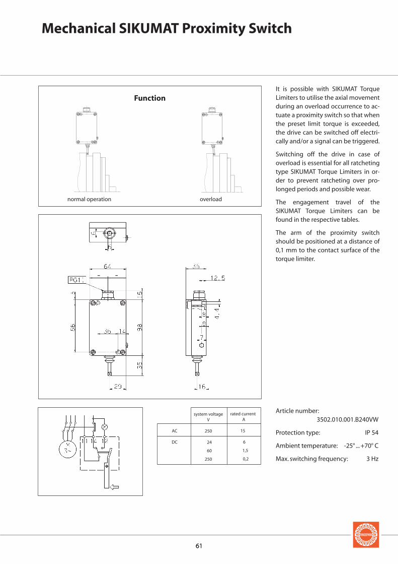
6161
Mechanical SIKUMAT Proximity Switch
It is possible with SIKUMAT TorqueLimiters to utilise the axial movementduring an overload occurrence to ac-tuate a proximity switch so that whenthe preset limit torque is exceeded,the drive can be switched off electri-cally and/or a signal can be triggered.
Switching off the drive in case ofoverload is essential for all ratchetingtype SIKUMAT Torque Limiters in or-der to prevent ratcheting over pro-longed periods and possible wear.
The engagement travel of the SIKUMAT Torque Limiters can befound in the respective tables.
The arm of the proximity switchshould be positioned at a distance of0,1 mm to the contact surface of thetorque limiter.
Article number: 3502.010.001.B240VW
Protection type: IP 54
Ambient temperature: -25° ... +70° C
Max. switching frequency: 3 Hz
Function
normal operation overload
AC
DC
system voltageV
250
24
60
250
rated currentA
15
6
1,5
0,2
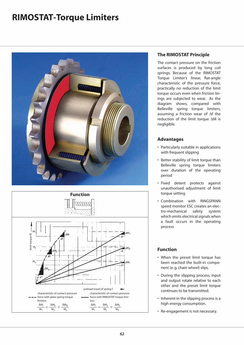
6262
RIMOSTAT-Torque Limiters
The RIMOSTAT Principle
The contact pressure on the frictionsurfaces is produced by long coilsprings. Because of the RIMOSTATTorque Limiter’s linear, flat-anglecharacteristic of the pressure force,practically no reduction of the limittorque occurs even when friction lin-ings are subjected to wear. As the diagram shows, compared withBelleville spring torque limiters, assuming a friction wear of Δf the reduction of the limit torque ΔM isnegligible.
Advantages
• Particularly suitable in applicationswith frequent slipping
• Better stability of limit torque thanBelleville spring torque limitersover duration of the operating period
• Fixed detent protects againstunauthorised adjustment of limittorque setting
• Combination with RINGSPANNspeed monitor ESC creates an elec-tro-mechanical safety systemwhich emits electrical signals whena fault occurs in the operatingprocess
Function
• When the preset limit torque hasbeen reached the built-in compo-nent (e. g. chain wheel) slips.
• During the slipping process, inputand output rotate relative to eachother and the preset limit torquecontinues to be transmitted.
• Inherent in the slipping process is ahigh energy consumption.
• Re-engagement is not necessary.
preload travel of spring f
limit
torq
ue
M
characteristic of contact pressureforce with plate spring torque limiters
ΔMI ΔMII ΔMIIIM1 M2 M3
> >
characteristic of contact pressureforce with RIMOSTAT torque limi-ters
ΔM1 ΔM2 ΔM3M1 M2 M3
= =
Function

A BX BY C2) D E2) L R
dH7
min. max.mm mm mm mm mm mm mm mm mm mm
6363
RS 40.1 4474.040.820 2 - 12 13 000 8 16 8 4,4 7 25 40 28 35,5 -RS 40.2 4474.040.920 4 - 25 13 000 8 16 8 4,4 7 25 40 28 35,5 -
RS 50.1 4474.050.820 4 - 25 10 500 9 20 8 5,2 8,7 32 50 36 45 -RS 50.2 4474.050.920 8 - 50 10 500 9 20 8 5,2 8,7 32 50 36 45 -
RS 63.1 4474.063.820 8 - 50 8 500 9 25 10 5,8 10,5 40 63 44 56 -RS 63.2 4474.063.920 16 - 100 8 500 9 25 10 5,8 10,5 40 63 44 56 -
RS 80.1 4474.080.820 10 - 100 6 700 15 32 12 5,8 15,3 50 80 55 71 -RS 80.2 4474.080.920 20 - 200 6 700 15 32 12 5,8 15,3 50 80 55 71 -
RS 100.1 4474.081.820 20 - 200 5 350 25 40 15 8,7 18 65 100 70 90 -RS 100.2 4474.081.920 40 - 375 5 350 25 40 15 8,7 18 65 100 70 90 -
RS 125.1 4474.082.820 40 - 375 4300 22 55 17 15,3 23 80 125 85 105 2,5RS 125.2 4474.082.920 75 - 750 4.300 22 55 17 15,3 23 80 125 85 105 2,5
RS 160.1 4474.083.820 75 - 750 3.350 40 70 22 15,3 28 100 160 105 130 5,5RS 160.2 4474.083.920 150 - 1 500 3.350 40 70 22 15,3 28 100 160 105 130 5,5
RS 200.1 4474.084.820 150 - 1 500 2.700 50 90 27 23 34 125 200 130 160 7,5RS 200.2 4474.084.920 300 - 3 000 2.700 50 90 27 23 34 125 200 130 160 7,5
RS 250.1 4474.085.820 300 - 3 000 2.100 55 115 34 28 41 160 250 165 185 9,0RS 250.2 4474.085.920 600 - 6 000 2.100 55 115 34 28 41 160 250 165 185 9,0
1) The max. speed relates to the design straight of the Torque Limiter; the max. permissable speed differential should be checked according to the heat calculation on page 68.2) If the part to be coupled is used without bearing bush, the bore should be made to dimension C (tolerance F8).Keyway as per DIN 6885, page 1 · Tolerance of keyway width P9
RIMOSTAT-Torque LimitersSeries RS
top of drgs.:Series RS withinstallation width Bx
bottom of drgs.:Series RS withinstallation width By
size 40 to 100 size 125 to 250
Width of parts to be connected:
Components may be connected with eitherwidth Bx or By.
Supply:
Unless requested otherwise, the Torque Lim-iters are supplied pilot bored, a full comple-ment of springs, without torque setting andwithout bearing bush. Factory torque setting isonly possible when the order includes a finishbore.
Accessories:
• Width Bx or By bearing bushes
• Standard tools are normally sufficient for ad-justing the torque. Only sizes 125 and 160 re-quire a tool adapter which can be orderedfrom us.
• RINGSPANN-Speed Control ESC
Please specify when ordering:
• Type of Torque Limiter
• Diameter d, if finish bore is requested
• Width of bearing bush Bx and By• Limit torque to be preset, if required
Technical Data and Dimensionstype art. no. limit max.
torque speed
Nm min-1
bore1)

6464
dH7
min. max. F
mm mm mmRS 40.1 4474.040.822 2 - 12 8 16 9,525 x 4,77 x 5,08 17 51,8 4,4 10,2RS 40.2 4474.040.922 4 - 25 8 16 9,525 x 4,77 x 5,08 17 51,8 4,4 10,2RS 40.1 4474.040.823 2 - 12 8 16 12,7 x 7,75 x 8,51 14 57,1 7 11,5RS 40.2 4474.040.923 4 - 25 8 16 12,7 x 7,75 x 8,51 14 57,1 7 11,5RS 50.1 4474.050.821 4 - 25 9 20 9,525 x 5,72 x 6,35 20 60,9 5,2 10,6 RS 50.2 4474.050.921 8 - 50 9 20 9,525 x 5,72 x 6,35 20 60,9 5,2 10,6RS 50.1 4474.050.823 4 - 25 9 20 15,87 x 9,65 x 10,16 14 71,3 8,7 12,4RS 50.2 4474.050.923 8 - 50 9 20 15,87 x 9,65 x 10,16 14 71,3 8,7 12,4RS 63.1 4474.063.822 8 - 50 9 25 12,7 x 6,4 x 8,51 20 81,2 5,8 12,9RS 63.2 4474.063.922 16 - 100 9 25 12,7 x 6,4 x 8,51 20 81,2 5,8 12,9RS 63.1 4474.063.823 8 - 50 9 25 19,05 x 11,68 x 12,07 14 85,6 10,5 15RS 63.2 4474.063.923 16 - 100 9 25 19,05 x 11,68 x 12,07 14 85,6 10,5 15RS 80.1 4474.080.822 10 - 100 15 32 12,7 x 6,4 x 8,51 23 93,3 5,8 15RS 80.2 4474.080.922 20 - 200 15 32 12,7 x 6,4 x 8,51 23 93,3 5,8 15RS 80.1 4474.080.823 10 - 100 15 32 25,4 x 17,02 x 15,88 13 106,1 15,3 19,8RS 80.2 4474.080.923 20 - 200 15 32 25,4 x 17,02 x 15,88 13 106,1 15,3 19,8RS 100.1 4474.081.821 20 - 200 25 40 15,87 x 9,65 x 10,16 24 121,6 8,7 19,5RS 100.2 4474.081.921 40 - 375 25 40 15,87 x 9,65 x 10,16 24 121,6 8,7 19,5RS 100.1 4474.081.823 20 - 200 25 40 31,75 x 19,56 x 19,05 13 132,7 18 24,1RS 100.2 4474.081.923 40 - 375 25 40 31,75 x 19,56 x 19,05 13 132,7 18 24,1RS 125.1 4474.082.821 40 - 375 22 55 25,4 x 17,02 x 15,88 19 154,3 15,3 24,8RS 125.2 4474.082.921 75 - 750 22 55 25,4 x 17,02 x 15,88 19 154,3 15,3 24,8RS 125.1 4474.082.823 40 - 375 22 55 38,1 x 25,4 x 25,4 14 171,2 23 28,7RS 125.2 4474.082.923 75 - 750 22 55 38,1 x 25,4 x 25,4 14 171,2 23 28,7RS 160.1 4474.083.821 75 - 750 40 70 25,4 x 17,02 x 15,88 23 186,5 15,3 29,7RS 160.2 4474.083.921 155 - 1.500 40 70 25,4 x 17,02 x 15,88 23 186,5 15,3 29,7RS 160.1 4474.083.823 75 - 750 40 70 50,8 x 30,99 x 29,21 13 212,3 28 36RS 160.2 4474.083.923 150 - 1.500 40 70 50,8 x 30,99 x 29,21 13 212,3 28 36RS 200.1 4474.084.821 150 - 1.500 50 90 38,1 x 25,4 x 25,4 20 243,6 23 38,5RS 200.2 4474.084.921 300 - 3.000 50 90 38,1 x 25,4 x 25,4 20 243,6 23 38,5RS 200.1 4474.084.823 150 - 1.500 50 90 63,5 x 38,1 x 39,37 13 265,4 34 44RS 200.2 4474.084.923 300 - 3.000 50 90 63,5 x 38,1 x 39,37 13 265,4 34 44RS 250.1 4474.085.821 300 - 3.000 55 115 44,45 x 30,99 x 27,94 21 298,3 28 48RS 250.2 4474.085.921 600 - 6.000 55 115 44,45 x 30,99 x 27,94 21 298,3 28 48RS 250.1 4474.085.823 300 - 3.000 55 115 76,2 x 45,72 x 48,26 14 342,4 41 54,5RS 250.2 4474.085.923 600 - 6.000 55 115 76,2 x 45,72 x 48,26 14 342,4 41 54,5
Chainwheel suitable for simple roller chain as per DIN
roller chain dimensions n° of teeth pitch circle-ø chainwheel-
pitch inner width roller-ø Z d0 width B
mm mm mm mm mm mm
RIMOSTAT-Torque LimitersSeries RS - with sprockets
size 40 to 100 size 125 to 250
Keyway as per DIN 6885, page 1 • Tolerance of keyway width P9
The glidebush is incorporated as standard. Further chainwheels available on request. Factory torque setting only possible for orders incl. finished bore.Further notes please refer to page 63.
Missing dimensionssee page 63
Technical Data and Dimensionstype art. no. limit
torque
Nm
bore
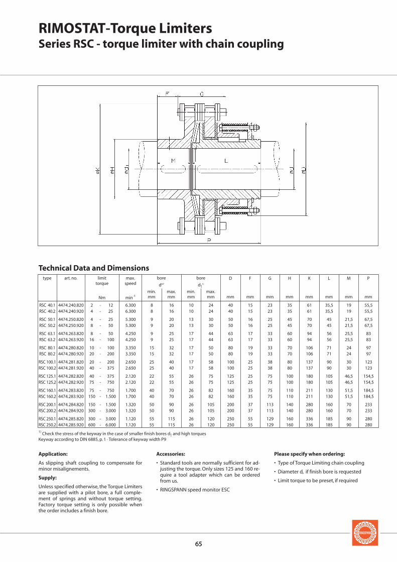
6565
D F G H K L M P
dH7 d11)
min. max. min. max.mm mm mm mm mm mm mm mm mm mm mm mm
RSC 40.1 4474.240.820 2 - 12 6.300 8 16 10 24 40 15 23 35 61 35,5 19 55,5RSC 40.2 4474.240.920 4 - 25 6.300 8 16 10 24 40 15 23 35 61 35,5 19 55,5
RSC 50.1 4474.250.820 4 - 25 5.300 9 20 13 30 50 16 25 45 70 45 21,5 67,5RSC 50.2 4474.250.920 8 - 50 5.300 9 20 13 30 50 16 25 45 70 45 21,5 67,5
RSC 63.1 4474.263.820 8 - 50 4.250 9 25 17 44 63 17 33 60 94 56 25,5 83RSC 63.2 4474.263.920 16 - 100 4.250 9 25 17 44 63 17 33 60 94 56 25,5 83
RSC 80.1 4474.280.820 10 - 100 3.350 15 32 17 50 80 19 33 70 106 71 24 97RSC 80.2 4474.280.920 20 - 200 3.350 15 32 17 50 80 19 33 70 106 71 24 97
RSC 100.1 4474.281.820 20 - 200 2.650 25 40 17 58 100 25 38 80 137 90 30 123RSC 100.2 4474.281.920 40 - 375 2.650 25 40 17 58 100 25 38 80 137 90 30 123
RSC 125.1 4474.282.820 40 - 375 2.120 22 55 26 75 125 25 75 100 180 105 46,5 154,5RSC 125.2 4474.282.920 75 - 750 2.120 22 55 26 75 125 25 75 100 180 105 46,5 154,5
RSC 160.1 4474.283.820 75 - 750 1.700 40 70 26 82 160 35 75 110 211 130 51,5 184,5RSC 160.2 4474.283.920 150 - 1.500 1.700 40 70 26 82 160 35 75 110 211 130 51,5 184,5
RSC 200.1 4474.284.820 150 - 1.500 1.320 50 90 26 105 200 37 113 140 280 160 70 233RSC 200.2 4474.284.920 300 - 3.000 1.320 50 90 26 105 200 37 113 140 280 160 70 233
RSC 250.1 4474.285.820 300 - 3.000 1.120 55 115 26 120 250 55 129 160 336 185 90 280RSC 250.2 4474.285.920 600 - 6.000 1.120 55 115 26 120 250 55 129 160 336 185 90 280
RIMOSTAT-Torque LimitersSeries RSC - torque limiter with chain coupling
1) Check the stress of the keyway in the case of smaller finish bores d1 and high torquesKeyway according to DIN 6885, p. 1 · Tolerance of keyway width P9
Application:
As slipping shaft coupling to compensate forminor misalignements.
Supply:
Unless specified otherwise, the Torque Limitersare supplied with a pilot bore, a full comple-ment of springs and without torque setting.Factory torque setting is only possible whenthe order includes a finish bore.
Accessories:
• Standard tools are normally sufficient for ad-justing the torque. Only sizes 125 and 160 re-quire a tool adapter which can be orderedfrom us.
• RINGSPANN speed monitor ESC
Please specify when ordering:
• Type of Torque Limiting chain coupling
• Diameter d, if finish bore is requested
• Limit torque to be preset, if required
Technical Data and Dimensionstype art. no. limit max.
torque speed
Nm min-1
bore bore

6666
Belleville Spring Torque Limiters
The Belleville Spring Principle
Belleville springs produce the con-tact force on the friction linings. Be-cause of the Belleville spring torquelimiters’ steep characteristic of thecontact force the spring preloadneeds to be readjusted when the fric-tion linings become worn. Bellevillespring Torque Limiters are thereforepreferred in applications where slip-ping periods are short and infre-quent.
Advantages
• Cost effective, simple Torque Limiter
• Sizes for torques from 0.5 Nm to 10 000 Nm
• Combination with RINGSPANNspeed monitor ESC creates an elec-tro-mechanical safety systemwhich emits electrical signals whena fault occurs in the operatingprocess; see catalogue 50.1 for fur-ther details
Function
• When the preset limit torque hasbeen reached the built-in compo-nent (e. g. chain wheel) slips.
• During the slipping process, inputand output rotate relative to eachother and the preset limit torquecontinues to be transmitted.
• Inherent in the slipping process is ahigh energy consumption.
• Re-engagement is not necessary.
Function
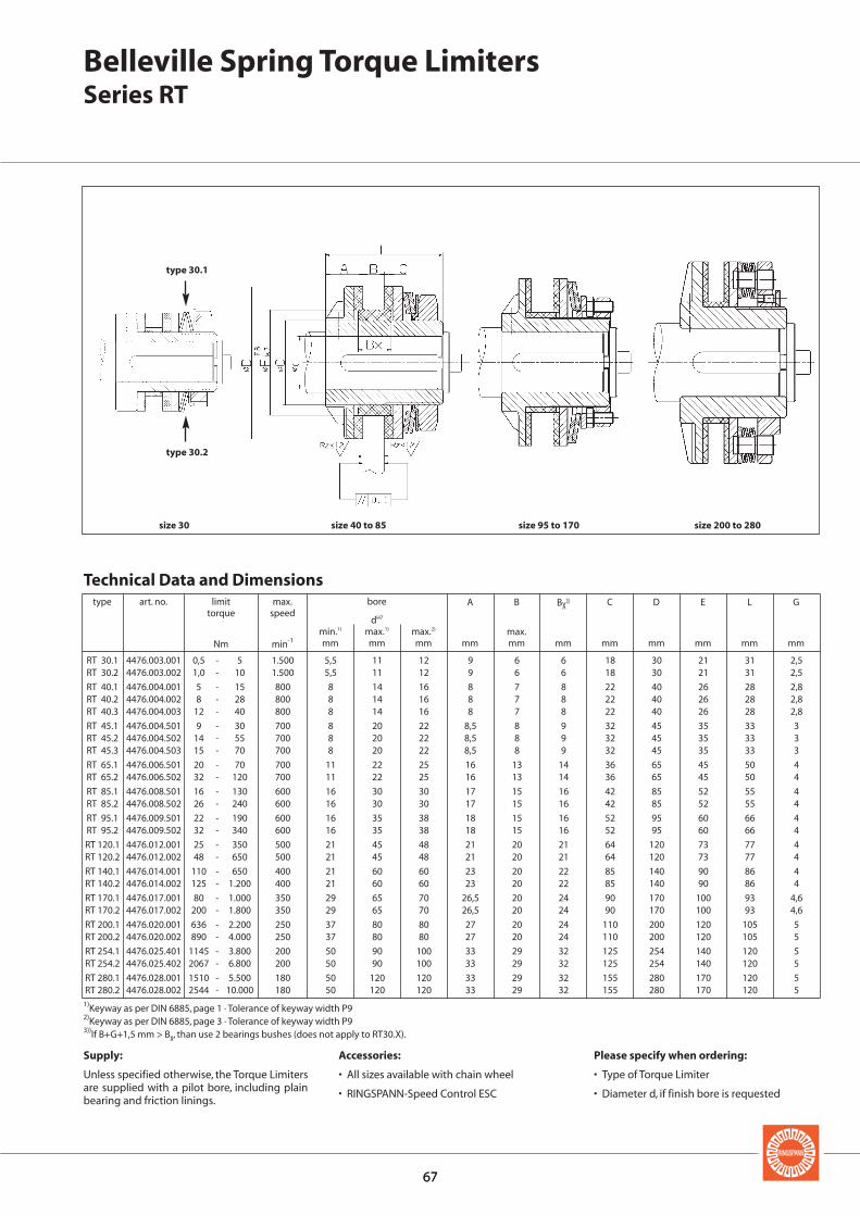
6767
A B BX3) C D E L G
dH7
min.1) max.1) max.2) max.mm mm mm mm mm mm mm mm mm mm mm
RT 30.1 4476.003.001 0,5 - 5 1.500 5,5 11 12 9 6 6 18 30 21 31 2,5RT 30.2 4476.003.002 1,0 - 10 1.500 5,5 11 12 9 6 6 18 30 21 31 2,5
RT 40.1 4476.004.001 5 - 15 800 8 14 16 8 7 8 22 40 26 28 2,8RT 40.2 4476.004.002 8 - 28 800 8 14 16 8 7 8 22 40 26 28 2,8RT 40.3 4476.004.003 12 - 40 800 8 14 16 8 7 8 22 40 26 28 2,8
RT 45.1 4476.004.501 9 - 30 700 8 20 22 8,5 8 9 32 45 35 33 3RT 45.2 4476.004.502 14 - 55 700 8 20 22 8,5 8 9 32 45 35 33 3RT 45.3 4476.004.503 15 - 70 700 8 20 22 8,5 8 9 32 45 35 33 3
RT 65.1 4476.006.501 20 - 70 700 11 22 25 16 13 14 36 65 45 50 4RT 65.2 4476.006.502 32 - 120 700 11 22 25 16 13 14 36 65 45 50 4
RT 85.1 4476.008.501 16 - 130 600 16 30 30 17 15 16 42 85 52 55 4RT 85.2 4476.008.502 26 - 240 600 16 30 30 17 15 16 42 85 52 55 4
RT 95.1 4476.009.501 22 - 190 600 16 35 38 18 15 16 52 95 60 66 4RT 95.2 4476.009.502 32 - 340 600 16 35 38 18 15 16 52 95 60 66 4
RT 120.1 4476.012.001 25 - 350 500 21 45 48 21 20 21 64 120 73 77 4RT 120.2 4476.012.002 48 - 650 500 21 45 48 21 20 21 64 120 73 77 4
RT 140.1 4476.014.001 110 - 650 400 21 60 60 23 20 22 85 140 90 86 4RT 140.2 4476.014.002 125 - 1.200 400 21 60 60 23 20 22 85 140 90 86 4
RT 170.1 4476.017.001 80 - 1.000 350 29 65 70 26,5 20 24 90 170 100 93 4,6RT 170.2 4476.017.002 200 - 1.800 350 29 65 70 26,5 20 24 90 170 100 93 4,6
RT 200.1 4476.020.001 636 - 2.200 250 37 80 80 27 20 24 110 200 120 105 5RT 200.2 4476.020.002 890 - 4.000 250 37 80 80 27 20 24 110 200 120 105 5
RT 254.1 4476.025.401 1145 - 3.800 200 50 90 100 33 29 32 125 254 140 120 5RT 254.2 4476.025.402 2067 - 6.800 200 50 90 100 33 29 32 125 254 140 120 5
RT 280.1 4476.028.001 1510 - 5.500 180 50 120 120 33 29 32 155 280 170 120 5RT 280.2 4476.028.002 2544 - 10.000 180 50 120 120 33 29 32 155 280 170 120 5
Technical Data and Dimensionstype art. no. limit max.
torque speed
Nm min-1
bore
Belleville Spring Torque LimitersSeries RT
type 30.1
type 30.2
size 30 size 40 to 85 size 95 to 170 size 200 to 280
Supply:
Unless specified otherwise, the Torque Limitersare supplied with a pilot bore, including plainbearing and friction linings.
Accessories:
• All sizes available with chain wheel
• RINGSPANN-Speed Control ESC
Please specify when ordering:
• Type of Torque Limiter
• Diameter d, if finish bore is requested
1)Keyway as per DIN 6885, page 1 · Tolerance of keyway width P92)Keyway as per DIN 6885, page 3 · Tolerance of keyway width P93))If B+G+1,5 mm > Bx, than use 2 bearings bushes (does not apply to RT30.X).

6868
Calculation of RIMOSTAT Torque Limiters
ML [Nm] Torque requirement of machine whilst operating
MLa [Nm] Average starting torque of machine
MK [Nm] Preset friction slip torqueof torque limiter
PL [kW] Rate of power input ofdriving half
n [r.p.m.] Speed when driving halfis running at nominalspeed
na [r.p.m.] Speed when torque limi-ter is slipping (drivenhalf )
Δn [r.p.m.] Speed differential bet-ween input and output
ta [s] Slipping time (see 2.1)
• For infrequent but longer slippingperiods the heat factor should bechecked against diagram 1.
• For constant friction or frequent,very short slipping periods theheat factor should be checkedagainst diagram 2.
The preset slip torque MK must ex-ceed the peak starting torque by atleast 25% and must be at least 25%higher than the normal running tor-que ML of the installation to be driven
For example, in the case of conveyorinstallations which are started whileunder load, the torque requirementduring the starting process is, afterovercoming the breakaway torque re-quirement during operation, i.e. MLa = ML. In the case of ventilators thetorque requirement at the beginningof the starting process can be verylow and increases during startingprocess with n2 i.e. approximatelyMLa = 0,5 • ML.
Selection of RIMOSTAT Torque Limi-ters is carried out of three stages:
1. Selection according to requiredtorque
2. Evaluation of slipping period andspeed differential
3. Checking the heat factor
The required operating torque can becalculated from the power absorptionof the machine:
PLML = 9 550 · [Nm] (1)n
The differential speed Δn changes du-ring the starting process from n (atthe beginning of the starting process)to 0 (after ending the starting pro-cess).
One can therefore apply the follow -ing calculation to determine the heat:
nΔn = [r.p.m.] (3)
2
Below are the basic guidelines to beapplied for the selection of RIMOSTATTorque Limiters:
• If slipping periods are short andvery infrequent, the highest trans-missible table torque may be utili-sed.
The torque to be transmitted by theRIMOSTAT Torque Limiter is to be taken from the tables, as is the per-missible speed.
2.1 Application as starter coupling
J · nta = [s] (2)
9,55 (MK–MLa)
For conversion of the old TechnicalStandard System apply J = 0,25 · GD2,entering GD2 as kpm2.The average starting torque MLa ofthe machine or installation during thestarting process depends on the typeof machine.
Symbols
Calculation of slipping period and friction power
1. Selection according to required torque load
Selection
J [kgm2] Mass inertia momentof rotating masses tobe accelerated, rela-tive to the speed ofthe torque limiter
Nm Standard-PR = W
s friction power
Nm OccuringPa = W
s friction power
Nm Max. permissiblePzul. = W
s friction power
[ ][ ][ ]

6969
Diagram 1 Diagram 2 (ambient temperature 20° C)
Using the calculated slipping time tathe standard friction power PR istaken from diagram 1 and multipliedwith size factor K according to thetable. The resulting friction power Pzul.of the selected torque limiter must begreater than the occuring frictionpower Pa.
The occurring friction power Pa mustbe calculated using formula (5).
3.2 Application as permanent slipping hub
It must be lower than the maximumtransmissible friction power Pzul. of
the given speed of the spring supportna, as shown in diagram 2.
Full utilisation of the maximum per-missible friction power Pzul. at an am-bient temperature of 20° C causes thetorque limiter to heat to ca. 220° C.
size size factor (K)
RS 40 0,13RS 50 0,21RS 63 0,35RS 80 0,6RS 100 1,0RS 125 1,7RS 160 2,9RS 200 5,1RS 250 7,5
The occuring friction power is calcu-lated as follows:
Pa = 0,105 · MK · Δn [W] (5)
Slipping time can be limited by safetydevices, e.g.:
• Speed monitors wich disengagethe motor when different speedsbetween input and output of thetorque limiter occur
• Thermal motor monitoring units
• Optical control (manual disengage-ment)
Assumming the driving side isblocked and the motor continues torun at full speed, the differentialspeed would amount to
Δn = n [r.p.m.] (4)
3.1 Application as starter- or safety coupling
2.2 Application as safety coupling 2.3 Friction Power
3. Checking the heat factor
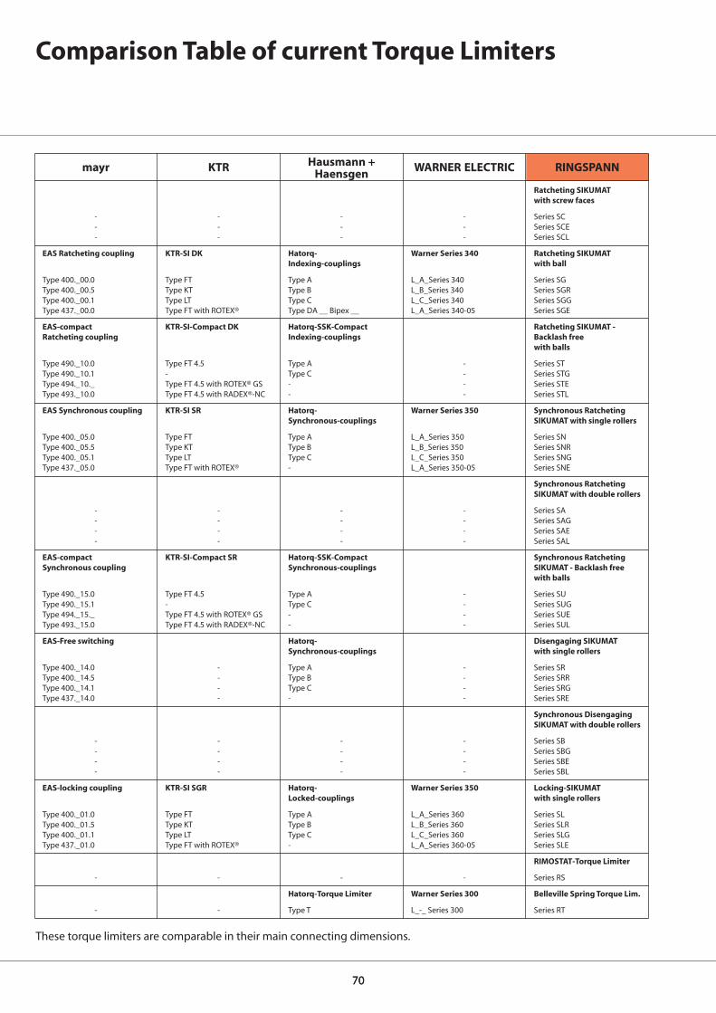
7070
Comparison Table of current Torque Limiters
These torque limiters are comparable in their main connecting dimensions.
RINGSPANN
Ratcheting SIKUMATwith screw faces
Series SCSeries SCESeries SCL
Ratcheting SIKUMAT with ball
Series SGSeries SGRSeries SGGSeries SGE
Ratcheting SIKUMAT - Backlash free with balls
Series STSeries STGSeries STESeries STL
Synchronous RatchetingSIKUMAT with single rollers
Series SNSeries SNRSeries SNGSeries SNE
Synchronous RatchetingSIKUMAT with double rollers
Series SASeries SAGSeries SAESeries SAL
Synchronous RatchetingSIKUMAT - Backlash freewith balls
Series SUSeries SUGSeries SUESeries SUL
Disengaging SIKUMATwith single rollers
Series SRSeries SRRSeries SRGSeries SRE
Synchronous DisengagingSIKUMAT with double rollers
Series SBSeries SBGSeries SBESeries SBL
Locking-SIKUMATwith single rollers
Series SLSeries SLRSeries SLGSeries SLE
RIMOSTAT-Torque Limiter
Series RS
Belleville Spring Torque Lim.
Series RT
mayr
---
EAS Ratcheting coupling
Type 400._00.0Type 400._00.5Type 400._00.1Type 437._00.0
EAS-compact Ratcheting coupling
Type 490._10.0Type 490._10.1Type 494._10._Type 493._10.0
EAS Synchronous coupling
Type 400._05.0Type 400._05.5Type 400._05.1Type 437._05.0
----
EAS-compactSynchronous coupling
Type 490._15.0Type 490._15.1Type 494._15._Type 493._15.0
EAS-Free switching
Type 400._14.0Type 400._14.5Type 400._14.1Type 437._14.0
----
EAS-locking coupling
Type 400._01.0Type 400._01.5Type 400._01.1Type 437._01.0
-
-
KTR
---
KTR-SI DK
Type FTType KTType LTType FT with ROTEX®
KTR-SI-Compact DK
Type FT 4.5-Type FT 4.5 with ROTEX® GSType FT 4.5 with RADEX®-NC
KTR-SI SR
Type FTType KTType LTType FT with ROTEX®
----
KTR-SI-Compact SR
Type FT 4.5-Type FT 4.5 with ROTEX® GSType FT 4.5 with RADEX®-NC
----
----
KTR-SI SGR
Type FTType KTType LTType FT with ROTEX®
-
-
Hausmann +Haensgen
---
Hatorq-Indexing-couplings
Type AType BType CType DA __ Bipex __
Hatorq-SSK-CompactIndexing-couplings
Type AType C--
Hatorq-Synchronous-couplings
Type AType BType C-
----
Hatorq-SSK-CompactSynchronous-couplings
Type AType C--
Hatorq-Synchronous-couplings
Type AType BType C-
----
Hatorq-Locked-couplings
Type AType BType C-
-
Hatorq-Torque Limiter
Type T
WARNER ELECTRIC
---
Warner Series 340
L_A_Series 340L_B_Series 340L_C_Series 340L_A_Series 340-05
----
Warner Series 350
L_A_Series 350L_B_Series 350L_C_Series 350L_A_Series 350-05
----
----
----
----
Warner Series 350
L_A_Series 360L_B_Series 360L_C_Series 360L_A_Series 360-05
-
Warner Series 300
L_-_ Series 300

Questionnaire for the selection of RINGSPANNTorque Limiters
Company:
Address:
Telephone:
Telefax:
Department:
Name:
Enquiry no.:
Date:
e-mail:
Type of machine,machine group orplant into which torque limiter is to be installed
1.
Effect2.
Arrangement as
Torque limiting through:� Ratcheting� Disengaging� Slipping
Backlash free torque transmission required? � yes � no
Re-engagement :� Automatic � Automatic-synchronous after 360°� Manual � Manual-synchronous after 360°
4.
3.
Shaft coupling (with co-axial shafts)
Input side: Shaft diameter ................................... mmLength .................................................. mm
Output side Shaft diameter ................................... mmLength .................................................. mm
� � Built-on coupling, on
� Shaft end: Diameter ................................. mmLength ...................................... mm
� Through-shaft dia.: Diameter ................................. mmLength ...................................... mm
Torque Limiter connects shaft with� Gear wheel � Chain wheel � Pulley� Other ..................... ..............................
Drive via5. A-synchronous motor
� Direct drive� �−Δ−[Star-delta] drive� Other electric motor, type:
� Combustion engineTypeNo. of cylindersOther
�
�
Output and speed6.
��
Output power .................... kW
Speed of torque limiter .................... min -1
Total output power via torque limiter
Output power only up to .................... % via torque limiter
Output side7.
�
Part of machine driven by the torque limiter Required torque load .................... NmIn case of irregular torque requirement: from .................. Nm to .................. Nm, frequency ...............HzDuring starting a maximum torque of .................... Nm may occurHow often will an overload occur? .................. times per yearPreset limit Torque .................... Nm(Limit torque must be 15% above maximum operating torque)
Installation conditions8. ����
�
In enclosed machine housingExposed, but in enclosed spaceIn oil bath or oil fogOutside,ambient temperatures from ………to ………ºCOther (accessibility, dust, etc.):
� If arranged as shaft coupling:
Max. parallel displacement of shafts: .................... mmMax. angular displacement: .................... degreesDistance between shaft ends: ..................mm
� Non-contact proximity switch � Speed control ESC� Mechanical proximity switch � Not necessary
Overload signal by9.
Estimated requirement: ............. Units (one off ) ............. Units per month ............. Units per year
please photocopy
For the selection of the torque limiter particular consideration should be given to the following:
Schaberweg 30–34 61348 Bad Homburg
Telefon +49 6172 275-0Telefax +49 6172 275-2 75

Freewheels
Brakes
Torque and Force Limiters
Couplings and Clamping Clutches
Shaft-Hub-Connections
Precision Clamping Fixtures
Backstops
Automatic protectionagainst reverserunning of conveyor belts,elevators, pumps and fans.
Catalogue 88
Indexing Freewheels
For gradual feed of materials.
Catalogue 80
Overrunning Clutches
Automatic engaging and disengaging of drives.
Catalogue 80
Freewheel Elements
Cage Freewheels,Sprag Sets andFreewheel Chains.
Catalogue 89
Industrial Disc Brakes
Manually actuated – manually released.
Catalogue 46
Industrial Disc Brakes
Spring actuated – pneumatically,hydraulically or manually released.
Catalogue 46
Industrial Disc Brakes
Pneumatically actuated –spring released.
Catalogue 46
Industrial Disc Brakes
Spring actuated – electromagneticallyreleased.
Catalogue 46
Industrial Disc Brakes
Hydraulically actuated –spring released.
Catalogue 46
Safety Clamping Unitspneumatically released
For secure and precise positioning of piston rods.
E01.023
Torque Limiters with Screw Face
Reliable overload protection for tough operating conditions.
Catalogue 45
Torque Limiters with Rollers
With double or single Rollers. Through ratcheting or disengaging,also for 360°synchronous running.
Catalogue 45
Torque Limiters with Balls
Reliable overload protection with maximum response accuracy. Also backlash free.
Catalogue 45
Torque Limiters with Friction Linings
RIMOSTAT Torque Limiter for con-stant torque.Belleville Spring Torque Limiter for simple release.
Catalogue 45
Force Limiters
Reliable axial overload protection in piston rods.
Catalogue 49
Flexible Couplings
Large, allowed radial and angularmisaligne-ments.Minimum resiliency.
Catalogue 44
Clamping Clutches
For the automatic coupling of rolls.Fast, safe and free from slipping connection.
Cone Clamping Elements
For shaft-hub connections.High torques with small dimensions.
Catalogue 31
Three-part Shrink Discs
External clamping connection for the fastening of hollow shafts on solid shafts
Catalogue 31
Star and Clamping Discs
Ideal for shaft-hub-connection for frequentrelease.
E03.023
Star Spring Washers
Axial spring element for preloading of ball bearings.
Catalogue 20
Standard Parts forClamping Fixtures
The RINGSPANN-System for the manufacture of your own precision clamping fixtures.
Catalogue 14
Standard ClampingFixtures
Standard program in high precision,ready manufac-tured chucks and mandrels.
Special ClampingFixtures
Custom made solutions for specific clamping problems.
Collet Mandrels
Universal, cost effective stan-dard series. Fast collet changeto other clamping diameters.
Catalogue 15
Hydraulic ExpandingClamping Tools
Mandrels and chucks withhigh concentricity.Clamping several workpieces in one process possible.
Catalogue 16
Two-part Shrink Discs
External clamping connection.Advantages:Simple, secure mounting even without torque wrench.
Catalogue 31.1
Housing Freewheels
Automatic engagingand disengaging formulti-motor drives for in-stallations with continu-ous operation.Catalogue 80.1
Flange-Couplings
Rigid, easily removable shaft coupling with no clearanceconeclamping elements.
E04.020
Safety Clamping Unitshydraulically released
For secure and precise positioning of piston rods.
Catalogue 32
Schaberweg 30–34 61348 Bad Homburg
Telefon +49 6172 275-0Telefax +49 6172 275-2 75
45e2
0 K
ron
ber
ger
Off
setd
ruck
Feb
ruar
200
7 · P
rin
ted
in G
erm
any