Torklift RV Electrical Parts Installation Instructions - CARiD · the bottom of the box. Use a...
21
IMPORTANT OWNEROPERATOR INSTALLATION INSTRUCTIONS A7706R / A7708R - A7711R / A7712R A7706RS / A7708RS - A7711RS / A7712RS Warning!! This battery box is made of aluminum and is Conductive! Do not allow the battery terminals to touch the aluminum Battery box. Be careful not to touch the battery box with a wrench while tightening the battery terminals, as this could cause a short!
Transcript of Torklift RV Electrical Parts Installation Instructions - CARiD · the bottom of the box. Use a...

IMPORTANT OWNER-‐OPERATOR INSTALLATION INSTRUCTIONS
A7706R / A7708R - A7711R / A7712R
A7706RS / A7708RS - A7711RS / A7712RS
Warning!! This battery box is made of aluminum and is
Conductive! Do not allow the battery terminals to touch the aluminum Battery box. Be careful not to touch the battery box with a wrench while
tightening the battery terminals, as this could cause a short!

Warning!! Improper installation of Solar Equipped Power Armors may
result in battery over-charging!
Solar Installation Option 1:
If you plan to use two batteries with a single 10-‐Watt Solar Panel, you will NOT need to purchase any additional parts.
Solar Installation Option 2:
If you plan to use one battery with a single 10-‐Watt Solar Panel, it is required that you use a 6 Amp Regulator (PN A7715) to prevent your battery from
gassing and over charging.
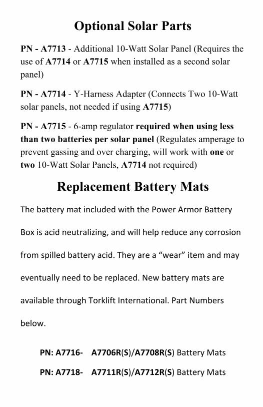
Optional Solar Parts PN - A7713 - Additional 10-Watt Solar Panel (Requires the use of A7714 or A7715 when installed as a second solar panel)
PN - A7714 - Y-Harness Adapter (Connects Two 10-Watt solar panels, not needed if using A7715)
PN - A7715 - 6-amp regulator required when using less than two batteries per solar panel (Regulates amperage to prevent gassing and over charging, will work with one or two 10-Watt Solar Panels, A7714 not required)
Replacement Battery Mats The battery mat included with the Power Armor Battery
Box is acid neutralizing, and will help reduce any corrosion
from spilled battery acid. They are a “wear” item and may
eventually need to be replaced. New battery mats are
available through Torklift International. Part Numbers
below.
PN: A7716-‐ A7706R(S)/A7708R(S) Battery Mats
PN: A7718-‐ A7711R(S)/A7712R(S) Battery Mats

Inventory List A7706R / A7708R - A7711R / A7712R
A7706RS / A7708RS - A7711RS / A7712RS Item: Quantity:
Power Armor Battery Box 1 Power Armor Lid 1 Angle Extension 2 Battery Mat 26” (A7706R / A7708R - A7706RS / A7708RS)
1
Battery Mat 23.5” (A7711R / A7712R - A7711RS / A7712RS)
1
Battery Strap 2 1/4" x 1” Self-Drilling Screw 6 1/4"-20 x 1” SS Hex Bolt 4 1/4"-20 x 2” Hex Bolt 4 1/4" SS USS Flat Washer 16 1/4"-20 SS Nylock Nuts 8 15A Fuse Holder (Solar Models Only) 1
1/4"x 5/8”x 1/4” Nylon Spacer 4
Figure 0.1
Short Side Holes
Long Side Holes
Long Side Holes
Inner Slots
Outer Slots

Step 1:
Remove the Power Armor Lid by sliding the lid away from the side with
the lock, then lifting the front edge and unhooking the lid from the tabs on
the rear of the box. The Power Armor Battery Box has four slots cut into
the bottom of the box. Use a sharp knife to make an incision in the Battery
Mat over each of the slots. This will allow for the Battery Straps to pass
through the slots.
Step 2:
On each side of the Power Armor Battery Box, insert the non-buckled end
of a Battery Strap down through the outer slot and back up through the
inner slot (see figure 0.1 for slot locations.) Leave approximately 10” of the
buckled end inside of the box.
Depending on mounting, the battery straps will not be able to slide through
the slots after the box is mounted. Place a battery into the Power Armor
Battery Box and adjust the Battery Straps into a suitable position on both
sides. Remove the battery and Battery Mat before proceeding.

Step 3:
The 2” hole in the front/back panel of the Power Armor Battery Box is
used to allow the battery cables to enter the battery box. It can be mounted
to either the front or rear of the trailer as long as there is sufficient room to
open and remove the Power Armor Lid. There are four mounting options
described in these instructions.
Option 1: PAGE 6: Mounting on top of the trailer A-frame. Use this
option if all four corners of the Power Armor Battery Box will sit on top
of the A-frame.
Option 2: PAGE 7: Mounting on top of the trailer A-frame using the
Angle Extension Brackets. Use this option if the box is not wide enough
for the rear corners to sit on the A-frame.
Option 3: PAGE 9: Mounting in the factory battery box location
between the rails. Use this option if your Power Armor Battery box will
fit in between the factory battery box support rails.
Option 4: PAGE 10: Mounting in the factory battery box location above
the rails. Use this option if your Power Armor Battery Box will mount in
the factory battery box location, but can’t fit between the battery support
rails.
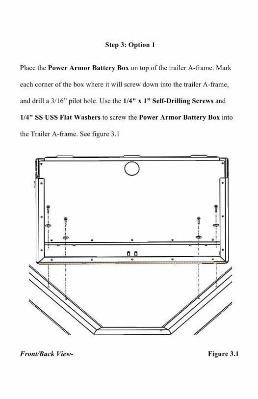
Step 3: Option 1
Place the Power Armor Battery Box on top of the trailer A-frame. Mark
each corner of the box where it will screw down into the trailer A-frame,
and drill a 3/16” pilot hole. Use the 1/4" x 1” Self-Drilling Screws and
1/4" SS USS Flat Washers to screw the Power Armor Battery Box into
the Trailer A-frame. See figure 3.1
Front/Back View- Figure 3.1

Step 3: Option 2
Measure the mounting width required for the rear of the Power Armor
Battery Box. Insert one 1/4"-20 x 1” SS Hex Bolt with one 1/4" SS USS
Washer into two of the “Long Side Holes” on each side of the battery box.
(see figure 0.1) Secure the Angle Extension Brackets to the box with one
1/4" SS USS Flat Washer and one 1/4"-20 SS Nylock nut per bolt. Any of
the slots in the Angle Extension Brackets can be used as long as the
previously measured mounting width is achieved. See figure 3.2
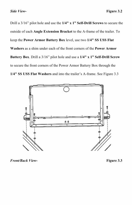
Side View- Figure 3.2
Drill a 3/16” pilot hole and use the 1/4" x 1” Self-Drill Screws to secure the
outside of each Angle Extension Bracket to the A-frame of the trailer. To
keep the Power Armor Battery Box level, use two 1/4" SS USS Flat
Washers as a shim under each of the front corners of the Power Armor
Battery Box. Drill a 3/16” pilot hole and use a 1/4" x 1” Self-Drill Screw
to secure the front corners of the Power Armor Battery Box through the
1/4" SS USS Flat Washers and into the trailer’s A-frame. See Figure 3.3
Front/Back View- Figure 3.3
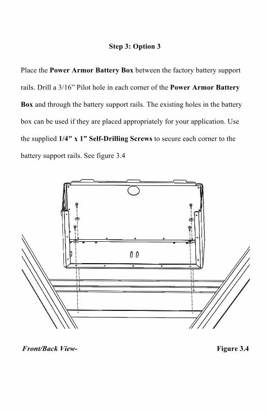
Step 3: Option 3
Place the Power Armor Battery Box between the factory battery support
rails. Drill a 3/16” Pilot hole in each corner of the Power Armor Battery
Box and through the battery support rails. The existing holes in the battery
box can be used if they are placed appropriately for your application. Use
the supplied 1/4" x 1” Self-Drilling Screws to secure each corner to the
battery support rails. See figure 3.4
Front/Back View- Figure 3.4

Step 3: Option 4
Begin by drilling two 1/4” holes in each of the battery support straps. For
A7706/A7708 Battery Boxes, the holes should be 25-1/4” apart. For
A7711/A7712 Battery Boxes, the holes should be 22-3/4” apart. (see
dimension “X” in figure 3.5)
Figure 3.5
Insert one 1/4"-20 x 2” Hex Bolt with one 1/4" SS USS Flat Washer down
through the slots of the Angle Extension Bracket and through each of the
holes previously drilled. The vertical flange on each Angle Extension
Bracket should be facing towards the outside of the trailer. Lightly secure
each bolt with one 1/4" SS USS Flat Washer and one 1/4"-20 SS Thin
Nylock Nut. Test fit to make sure the “Short Side Holes” in the Power
Armor Battery Box will align with the slots in the Angle Extension
Brackets. Adjust as necessary and tighten the 1/4"-20 x 2” Hex Bolts. See
figure 3.6
X

Figure 3.6
Insert one 1/4"-20x 1” SS Hex Bolt with one 1/4" SS USS Flat Washer
into all four “Short Side Holes” on the Power Armor Battery Box. Place
one 1/4"x 5/8”x 1/4” Nylon Spacer between the battery box and Angle
Extension Brackets. Secure each bolt with one 1/4" SS USS Flat Washer
and one 1/4"-20 Nylock Nut. See figure 3.7

Figure 3.7

Step 4
Reinstall the Battery Mat and Batteries. To prevent any possible contact
between the battery terminals and lock, the battery terminals should be
oriented towards the side of the box with the 2” hole. Tightly secure the
batteries with the battery straps.
Step 5
The Power Armor and Power Armor Solar battery boxes are capable of
supporting multiple battery configurations. Depending on the configuration,
additional battery cables may be required but are not included.
Option 1: PAGE 14: Wiring for a single 12v battery
Option 2: PAGE 14: Wiring for two 12v batteries
Option 3: PAGE 15: Wiring for two 6v batteries

Step 5: Option 1
Insert the positive and negative battery cables into the box through the 2”
hole. Connect the positive battery cable to the positive terminal on the
battery. Connect the negative battery cable to the negative terminal on the
battery.
Solar Models Only: For Power Armor Solar customers, a 6 amp regulator
will be required for this installation option. Attach the supplied fuse holder
to the positive wire on the SAE connector. Connect the positive wire from
the SAE connector to the positive terminal on the battery. Connect the
negative wire from the SAW connector to the negative terminal on the
battery.
Step 5: Option 2
Insert the positive and negative battery cables into the box through the 2”
hole. Connect the positive cable from the camper to the positive terminal on
one of the batteries. Connect the negative cable from the camper to the
negative terminal on the other battery. Install one cable connecting both
positive battery terminals together. Install one cable connecting both
negative battery terminals together. See diagram 5.1. This configuration will
produce a 12v power source from two 12v batteries.

Solar Models Only: Attach the supplied fuse holder to the positive wire on
the SAE connector. Connect the positive and negative wires from the SAE
connector as shown in figure 5.1
Figure 5.1
Step 5: Option 3
Insert the positive and negative battery cables into the box through the 2”
hole. Connect the positive cable from the camper to the positive terminal on
one of the batteries. Install one cable connecting the unused negative
terminal on the first battery to the unused positive terminal on the second
battery. This configuration will create a 12v Power Source from two 6v
batteries.
Power Armor Solar Only
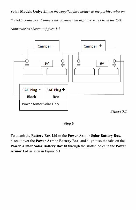
Solar Models Only: Attach the supplied fuse holder to the positive wire on
the SAE connector. Connect the positive and negative wires from the SAE
connector as shown in figure 5.2
Figure 5.2
Step 6
To attach the Battery Box Lid to the Power Armor Solar Battery Box, place it over the Power Armor Battery Box, and align it so the tabs on the Power Armor Solar Battery Box fit through the slotted holes in the Power Armor Lid as seen in Figure 6.1
Power Armor Solar Only
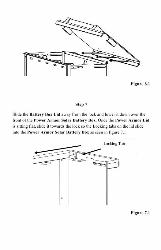
Figure 6.1
Step 7
Slide the Battery Box Lid away from the lock and lower it down over the front of the Power Armor Solar Battery Box. Once the Power Armor Lid is sitting flat, slide it towards the lock so the Locking tabs on the lid slide into the Power Armor Solar Battery Box as seen in figure 7.1
Figure 7.1
Locking Tab

After the Battery Box Lid has slid into place, lock the key cylinder as seen in figure 7.2.
Solar Models Only: Connect the SAE connector from the Solar Panel into the SAE connector on the side of the Power Armor Solar Battery Box.
Figure 7.2

RECOMMENDED TRUCK CAMPER INSTALLATION INSTRUCTIONS
When securing any heavy load (especially a camper) in your truck bed, your front tie down points should pull the load forward as much as possible. Some camper anchor points may differ with different manufacturers, as well as the camper jack mounting locations. Your Torklift tie down inserts have offset triangular brackets to increase the angle of pull. These are designed to be used in the front facing forward, and the rear facing rearward but can be used in either front or rear. These recommendations are to be considered and followed as a basic rule of thumb . Obviously there will be some applications where this may not be possible. At a minimum, if opposite pull of both front and rear Tiedowns cannot be achieved for whatever reason, you should have at least a forward pull at the front or rear location. If your camper does not come with Rubber Bumpers on the front lower portion of the camper, installing Rubber Bumpers (Torklift has Rubber Bumpers available Part A7001) or using a block of wood such as a 2 x 4 in the bed, will prevent the camper from damaging the front bulk head of the truck bed. Minor movement (or settling) can occur in some incidental harsh driving conditions (on or off road). A rubber bed mat is not a requirement to maintain the lifetime warranty on a Torklift system, but a strong recommendation simply as a safety precaution to protect the truck bed, the bottom of the camper and to give the camper additional support.
TORKLIFT DOES NOT RECOMMEND: Installing your truck camper in your truck on top of a drop in plastic bed liner!!! The drop in plastic bed liners can slide on top of the truck bed surface, and the camper can slide on top of the slick surface of the bed liner. The liner can also act as a spring causing a trampoline effect increasing vertical truck camper movement, independent of the vehicle, possibly resulting in truck bed, and camper damage!
INSTRUCTIONS FOR FINISH MAINTENANCE OF TORKLIFT PRODUCTS
POWDER COATED STEEL: To keep your Torklift products looking good follow these guidelines. All steel powder coated Torklift products are sandblasted for maximum adhesion and use a high quality industrial urethane based powder coat. Due to the extreme, harsh, undercar environment that your Torklift products live in, (consistently sprayed with corrosive road chemicals such as salt, and road debris), Torklift does not warranty the power coated finish. To minimize corrosion from these factors on powder coated steel products, Torklift recommends regularly cleaning and inspecting the powder coated surface and touching up any affected areas with an enamel or urethane based aerosol paint product. If there are any areas of surface rust, there are also aerosol spray rust converters available on the market that can be used as a preparation to touch-up paint application. These finish maintenance products are available at any automotive parts supplier.
POLISHED STAINLESS STEEL : TorkLift utilizes quality grade 304 stainless steel in our stainless steel polished products. 304 stainless steel is well known for its anti-corrosive properties. However, in some environments such as coastal regions or when coming in contact with some road chemicals, corrosion may occur. For a quick clean simply use WD40 and a cloth rag. We also recommend occasional polishing of our polished stainless products to maintain their attractive finish. Use an approved stainless steel chrome or aluminum mag wheel polish cleaning product which can be purchased from any automotive parts supplier.

Frame Mounted Tie Downs Leading the camper tie down industry in strength, quality, advanced design and installation. TorkLift TRUE frame mounted tie downs are far superior to all tie down systems available.
The TorkLift system is unique in its design and is patented. Four independent tie down points (with no belly or crossbar) working much like your receiver type trailer hitch as the inserts are
removable allowing the system to be virtually undetectable when not in use. They are designed for each make and model to fit tight to the frame so as not to compromise ground clearance. Torklift tie downs are not universal ‘one size fits all’ therefore all the problems with correct fit for each particular application have been eliminated.
SuperHitch Magnum 20K & SuperHitch Magnum 30K
High strength extended hitch system engineered for safely towing all types of trailers behind your truck and camper. With a max towing capacity of 14,000 lbs.(6350Kg). with an extension* , (20,000 lbs.(9071Kg) to 30,000 lbs (13607 Kg) ( without*) the SuperHitch Magnum 20K and SuperHitch Magnum 30K are rated the strongest in the industry.
CONTACT YOUR LOCAL DEALER FOR MORE DETAILS