
Topology Optimization of Algorithmically Generated...
7
Proceedings of the International Association for Shell and Spatial Structures (IASS) Symposium 2013 „BEYOND THE LIMITS OF MAN” 23-27 September, Wroclaw University of Technology, Poland J.B. Obrębski and R. Tarczewski (eds.) 1 Topology Optimization of Algorithmically Generated Space Frames Paul Shepherd 1 , Will Pearson 2 1 Lecturer in Digital Architectonics, Department of Architecture & Civil Engineering, University of Bath, Bath, UK, [email protected] 2 Researcher, Department of Architecture & Civil Engineering, University of Bath, Bath, UK, [email protected] Summary: This paper outlines a simple method for algorithmically generating efficient space-frame geometries. By using Conway operators, the top and bottom surface of a shell-like space frame is generated, and these two layers are then linked together to form a structurally sound space-frame. The structural performance of the frames is then improved by applying existing structural layout optimisation methods, resulting in an efficient and elegant way of generating efficient and elegant structures. Keywords: Topology, Layout, Optimisation, Subdivision Surface, Space Frame, Conway Operator, Computation, Geometry. 1. INTRODUCTION Doubly-curved structural forms are becoming more popular as an expression of architectural creativity and the application of modern technology to building design. If the shape of such a form is carefully chosen to respect the flow of forces within, an efficient structural system can be derived in which the majority of the dominant forces lie within the structural depth and are transmitted down to the foundations as axial forces within the members, reducing the required resistance in bending. Such funicular forms provide elegant solutions, and are the result of structural efficiency being placed high on the list of design priorities. However, this approach is becoming less common, and other architectural requirements are beginning to dominate, driving the design away from pure shell-like solutions into the realm of free-form ‘sculpture’. In such cases, a single layer of structure may no longer produce an efficient design, as member depth needs to be increased substantially in order to accommodate the resulting bending moments of these non-funicular forms. The structural typology therefore moves away from the single layer grid towards a truss-like solution, or its two- way spanning equivalent the space-frame. This paper outlines a flexible approach to the development of efficient space-frame solutions to doubly-curved structural forms. It combines structural grid generation tools such as Subdivision Surfaces [1] and Conway operators [2] to algorithmically generate upper- and lower-layer structural grids. It incorporates a novel and efficient topology layout optimization algorithm developed by Gilbert & Tyas [3] to connect the two layers together. This leads to an efficient structural solution, which minimizes material, and can take into account practical considerations such as member buckling and joint costs. The result is a robust and flexible tool to explore potential solutions, guiding the designer towards structurally sound designs whilst still allowing the user the freedom and control to express their design intent. Carefully harnessing the power of the computer in this way can give rise to complex solutions which would otherwise be ‘Beyond the limits of Man’. 2. FRAME GENERATION The techniques outlined in this paper are widely applicable. However, in order to facilitate a clear and simplified explanation of the underlying research, the scope of this paper has been limited to the design of a space-frame supporting structure for a doubly-curved roof surface. In this context, the designer, be they architect or engineer, may or may not have a clear idea of the exact geometry of the roof they wish to build, but certainly have an open mind towards the structure which will support it. This section can only give a brief overview of space frame design covering the issues pertinent to the proposed approach. For a more complete and in-depth treatment the authors recommend the excellent book by Chilton [4]. 2.1. Initial Surface Mesh Given modern digital design processes it is likely that an initial roof geometry will be defined using a doubly-curved NURBS surface. However, in order to support such a surface with discrete structural members, and perhaps also driven by cladding constraints, such a continuous NURBS surface is almost always discretized into a mesh- like hierarchy of members meeting at nodes, with or without cladding faces, before structural- and façade-engineering is considered. Often the underlying NURBS surface is simply sampled at regular intervals using its underlying UV parameterization, leading to a topologically quadrilateral grid of members. Depending on the relative importance of respecting the original surface vs. rationalizing the geometry of the resulting façade panels, alternatively methods might be used which approximate the NURBS surface but lead to planar panels [5] or parametric surfaces (i.e. torus patches). Two surface mesh construction algorithms are particularly relevant to this research. If the exact geometry of the surface is not important, Subdivision Surfaces present a simple and useful method of generating candidate structural meshes. Their implementation involves a topological refinement of a coarse sampling of the original surface, followed by a geometrical smoothing process which maintains C2 continuity (i.e. rate- of-change of surface normal). This recursive, fractal-like nature provides control over the size of the mesh facets and C2 continuity results in a smooth and aesthetically pleasing approximation of the original surface. Subdivision Surfaces can be constrained to a prescribed boundary and methods are available to vary the density of the mesh across the surface to respect the underlying structural behavior. A detailed explanation of Subdivision Surfaces is outside the scope of this paper, but is dealt with in detail in many previous works by the author, for example [1]. 2.2. Conway Operators In order to respect the original surface geometry, the smoothing part of the Subdivision algorithm is no longer appropriate. Hence only topological operations can be performed, and newly introduced nodes might be projected back onto the original surface. In this case, Conway Operators [2] offer a simple means of manipulating candidate structural grids to provide the designer with a myriad of options, and such operations lend themselves easily to implementation in computer programs and parametric modeling systems. There are three basic Conway operators, dual, ambo and kis. Each replaces the vertices, edges and faces of an original mesh with some combination of new vertices, edges and faces, depending on the operation. For example the dual operator, as visualized in Fig. 1, replaces every vertex with a face and every face with a vertex. It has been widely used in building design, since the relation of the dual to the original topology lends itself well to providing supporting structure for panels. The lesser known operations of ambo and kis (see Fig. 2 & Fig. 3 respectively) present additional methods of topology manipulation and in the case of space-frame design are equally of interest.
Transcript of Topology Optimization of Algorithmically Generated...
Proceedings of the International Association for
Shell and Spatial Structures (IASS) Symposium 2013 „BEYOND THE LIMITS OF MAN”
23-27 September, Wroclaw University of Technology, Poland
J.B. Obrębski and R. Tarczewski (eds.)
1
Topology Optimization of Algorithmically Generated Space Frames
Paul Shepherd1, Will Pearson2
1 Lecturer in Digital Architectonics, Department of Architecture & Civil Engineering, University of Bath, Bath, UK, [email protected] 2 Researcher, Department of Architecture & Civil Engineering, University of Bath, Bath, UK, [email protected]
Summary: This paper outlines a simple method for algorithmically generating efficient space-frame geometries. By using Conway operators, the top and bottom surface of a shell-like space frame is generated, and these two layers are then linked together to form a structurally sound space-frame.
The structural performance of the frames is then improved by applying existing structural layout optimisation methods, resulting in an efficient and
elegant way of generating efficient and elegant structures.
Keywords: Topology, Layout, Optimisation, Subdivision Surface, Space Frame, Conway Operator, Computation, Geometry.
1. INTRODUCTION
Doubly-curved structural forms are becoming more popular as an expression of architectural creativity and the application of modern
technology to building design. If the shape of such a form is carefully
chosen to respect the flow of forces within, an efficient structural system can be derived in which the majority of the dominant forces lie within
the structural depth and are transmitted down to the foundations as axial
forces within the members, reducing the required resistance in bending. Such funicular forms provide elegant solutions, and are the result of
structural efficiency being placed high on the list of design priorities.
However, this approach is becoming less common, and other architectural requirements are beginning to dominate, driving the design
away from pure shell-like solutions into the realm of free-form
‘sculpture’. In such cases, a single layer of structure may no longer produce an efficient design, as member depth needs to be increased
substantially in order to accommodate the resulting bending moments of
these non-funicular forms. The structural typology therefore moves away from the single layer grid towards a truss-like solution, or its two-
way spanning equivalent the space-frame.
This paper outlines a flexible approach to the development of efficient space-frame solutions to doubly-curved structural forms. It combines
structural grid generation tools such as Subdivision Surfaces [1] and
Conway operators [2] to algorithmically generate upper- and lower-layer structural grids. It incorporates a novel and efficient topology layout
optimization algorithm developed by Gilbert & Tyas [3] to connect the
two layers together. This leads to an efficient structural solution, which minimizes material, and can take into account practical considerations
such as member buckling and joint costs.
The result is a robust and flexible tool to explore potential solutions,
guiding the designer towards structurally sound designs whilst still
allowing the user the freedom and control to express their design intent.
Carefully harnessing the power of the computer in this way can give rise to complex solutions which would otherwise be ‘Beyond the limits of
Man’.
2. FRAME GENERATION
The techniques outlined in this paper are widely applicable. However,
in order to facilitate a clear and simplified explanation of the underlying
research, the scope of this paper has been limited to the design of a space-frame supporting structure for a doubly-curved roof surface. In
this context, the designer, be they architect or engineer, may or may not
have a clear idea of the exact geometry of the roof they wish to build, but certainly have an open mind towards the structure which will
support it. This section can only give a brief overview of space frame
design covering the issues pertinent to the proposed approach. For a more complete and in-depth treatment the authors recommend the
excellent book by Chilton [4].
2.1. Initial Surface Mesh
Given modern digital design processes it is likely that an initial roof geometry will be defined using a doubly-curved NURBS surface.
However, in order to support such a surface with discrete structural
members, and perhaps also driven by cladding constraints, such a continuous NURBS surface is almost always discretized into a mesh-
like hierarchy of members meeting at nodes, with or without cladding
faces, before structural- and façade-engineering is considered. Often the underlying NURBS surface is simply sampled at regular intervals using
its underlying UV parameterization, leading to a topologically
quadrilateral grid of members. Depending on the relative importance of respecting the original surface vs. rationalizing the geometry of the
resulting façade panels, alternatively methods might be used which
approximate the NURBS surface but lead to planar panels [5] or parametric surfaces (i.e. torus patches). Two surface mesh construction
algorithms are particularly relevant to this research.
If the exact geometry of the surface is not important, Subdivision Surfaces present a simple and useful method of generating candidate
structural meshes. Their implementation involves a topological
refinement of a coarse sampling of the original surface, followed by a geometrical smoothing process which maintains C2 continuity (i.e. rate-
of-change of surface normal). This recursive, fractal-like nature
provides control over the size of the mesh facets and C2 continuity results in a smooth and aesthetically pleasing approximation of the
original surface. Subdivision Surfaces can be constrained to a
prescribed boundary and methods are available to vary the density of the mesh across the surface to respect the underlying structural behavior. A
detailed explanation of Subdivision Surfaces is outside the scope of this
paper, but is dealt with in detail in many previous works by the author,
for example [1].
2.2. Conway Operators
In order to respect the original surface geometry, the smoothing part of the Subdivision algorithm is no longer appropriate. Hence only
topological operations can be performed, and newly introduced nodes
might be projected back onto the original surface. In this case, Conway Operators [2] offer a simple means of manipulating candidate structural
grids to provide the designer with a myriad of options, and such
operations lend themselves easily to implementation in computer programs and parametric modeling systems.
There are three basic Conway operators, dual, ambo and kis. Each
replaces the vertices, edges and faces of an original mesh with some combination of new vertices, edges and faces, depending on the
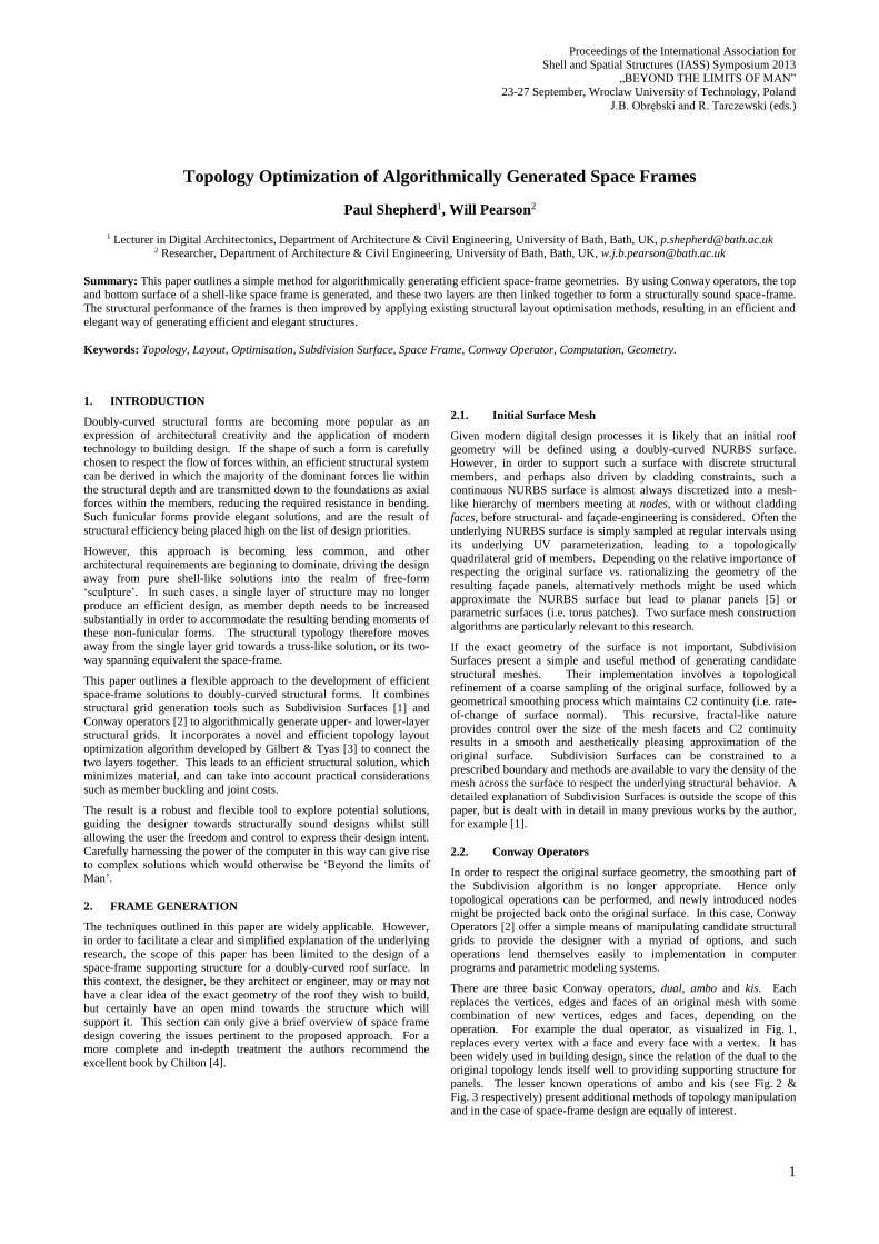
operation. For example the dual operator, as visualized in Fig. 1,
replaces every vertex with a face and every face with a vertex. It has been widely used in building design, since the relation of the dual to the
original topology lends itself well to providing supporting structure for panels. The lesser known operations of ambo and kis (see Fig. 2 &
Fig. 3 respectively) present additional methods of topology manipulation
and in the case of space-frame design are equally of interest.
2
Fig. 1 Original hexagonal mesh (blue dashes) with its dual (orange)
Fig. 2 Hexagonal mesh (blue dashes) with its ambo (orange)
Fig. 3 Hexagonal mesh (blue dashes) with its kis (orange)
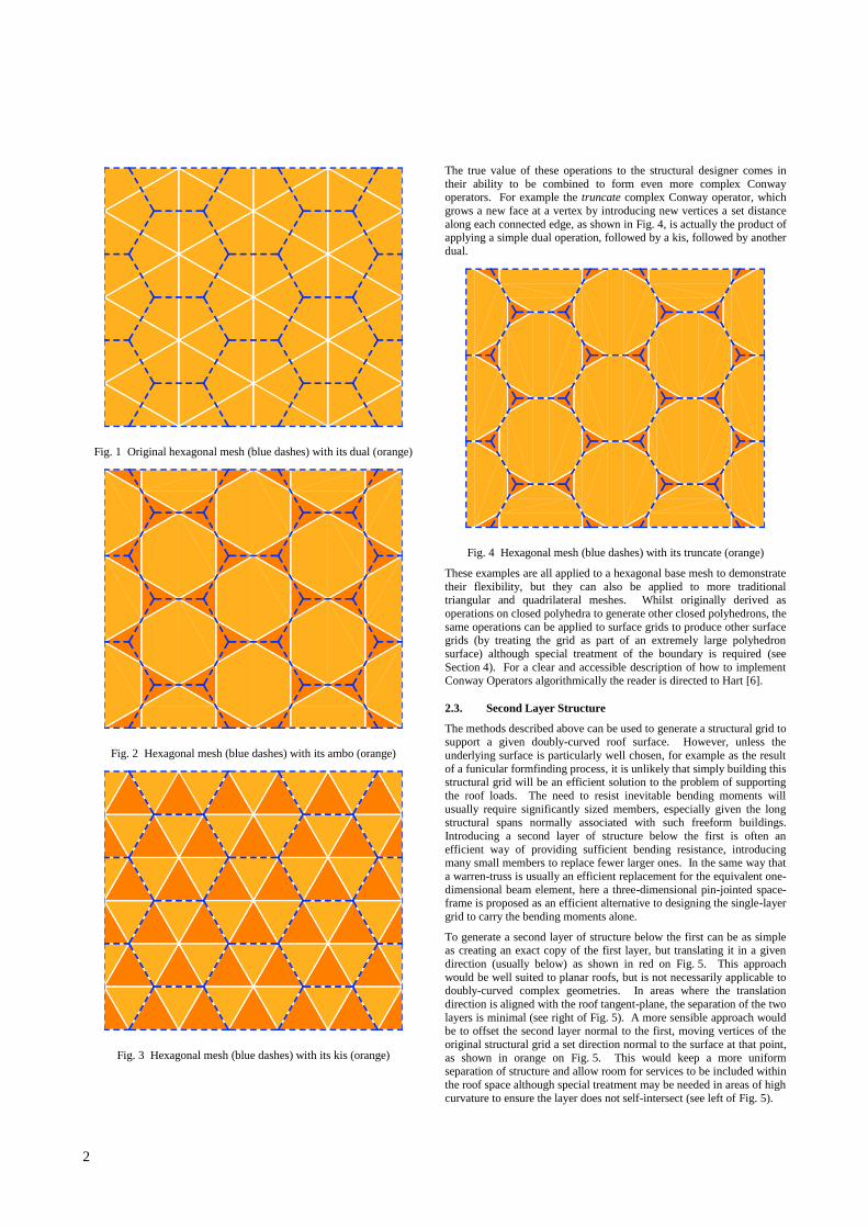
The true value of these operations to the structural designer comes in
their ability to be combined to form even more complex Conway operators. For example the truncate complex Conway operator, which
grows a new face at a vertex by introducing new vertices a set distance
along each connected edge, as shown in Fig. 4, is actually the product of applying a simple dual operation, followed by a kis, followed by another
dual.
Fig. 4 Hexagonal mesh (blue dashes) with its truncate (orange)
These examples are all applied to a hexagonal base mesh to demonstrate
their flexibility, but they can also be applied to more traditional triangular and quadrilateral meshes. Whilst originally derived as
operations on closed polyhedra to generate other closed polyhedrons, the
same operations can be applied to surface grids to produce other surface grids (by treating the grid as part of an extremely large polyhedron
surface) although special treatment of the boundary is required (see
Section 4). For a clear and accessible description of how to implement Conway Operators algorithmically the reader is directed to Hart [6].
2.3. Second Layer Structure
The methods described above can be used to generate a structural grid to support a given doubly-curved roof surface. However, unless the
underlying surface is particularly well chosen, for example as the result
of a funicular formfinding process, it is unlikely that simply building this structural grid will be an efficient solution to the problem of supporting
the roof loads. The need to resist inevitable bending moments will
usually require significantly sized members, especially given the long
structural spans normally associated with such freeform buildings.
Introducing a second layer of structure below the first is often an
efficient way of providing sufficient bending resistance, introducing many small members to replace fewer larger ones. In the same way that
a warren-truss is usually an efficient replacement for the equivalent one-
dimensional beam element, here a three-dimensional pin-jointed space-frame is proposed as an efficient alternative to designing the single-layer
grid to carry the bending moments alone.
To generate a second layer of structure below the first can be as simple as creating an exact copy of the first layer, but translating it in a given
direction (usually below) as shown in red on Fig. 5. This approach
would be well suited to planar roofs, but is not necessarily applicable to doubly-curved complex geometries. In areas where the translation
direction is aligned with the roof tangent-plane, the separation of the two
layers is minimal (see right of Fig. 5). A more sensible approach would be to offset the second layer normal to the first, moving vertices of the
original structural grid a set direction normal to the surface at that point,
as shown in orange on Fig. 5. This would keep a more uniform separation of structure and allow room for services to be included within
the roof space although special treatment may be needed in areas of high
curvature to ensure the layer does not self-intersect (see left of Fig. 5).

Proceedings of the International Association for
Shell and Spatial Structures (IASS) Symposium 2013 „BEYOND THE LIMITS OF MAN”
23-27 September, Wroclaw University of Technology, Poland
J.B. Obrębski and R. Tarczewski (eds.)
3
Fig. 5 An original structural layer (blue dashes) with its vertical offset
(red) and normal offset (orange)
The amount of separation between the two layers need not be constant.
It would seem sensible to increase the separation, and therefore the
resulting structural depth of the space-frame, in areas where bending is likely to be higher. This could be calculated explicitly if non-uniform
loading were dominant. However simply using the local curvature at a
vertex to define the offset for that vertex is a sensible starting point.
The second layer need not retain the topology of the first. Subdivision
Surface operations might be more applicable here than on the first layer
since the exact position of the second layer is usually less critical (it has been generated by the structural designer and not the roof designer
anyway). Certainly further Conway operators can be applied to the
second layer to generate alternative patterns. The dual operator has been used historically for the second layer of a space frame since the
topological relation between the two allows for east connection between
them (see below). However other Conway operators, and combinations of them, can lead to a wide range of patterns for second layers. And the
mathematical nature of the operations leads to some interesting
properties when it comes to connecting the two layers
2.4. Inter-layer Connection
Depending on the topological relationship between the two layers of
structure, various methods of connecting the two present themselves. In the simplest case of offsetting one layer from another, the simplest
solution to connecting them would be to join each vertex on one layer to
its corresponding vertex on the other. For structural stability, this would require moment connections at each node, in a similar way to a
Vierendeel truss. In node and bar structures, providing this moment connection is often difficult and therefore in this paper only pin-jointed
structures are considered. This requires the introduction of diagonal
elements between layers, either as well as the direct connecting elements (as with a Pratt truss) or instead of the direct elements (as with a Warren
truss).
Fig. 6 Original layer (blue), connected (in grey) to its dual (orange)
If the second layer has a different topology to the first, for example as the result of Conway operators, then an appropriate method of joining
the two layers needs to be derived. Rules of thumb can be derived, for
example when an operation converts vertices to faces (such as a single dual or ambo) each vertex of the original layer can be connected to
every vertex of the corresponding face on the second layer (see Fig. 6).
Similarly for a kis operation which introduces an extra vertex in the second layer corresponding to the center of a face in the first, the new
vertex can be connected back to those surrounding its corresponding
face. However the vast array of possible relationships from the infinite combinations of Conway operators makes explicit tabulation of such
rules impossible.
An alternative and simpler, if less elegant, method of connecting the two layers is to simply join each vertex in the first layer to any vertex in the
second if the distance between them is less than a chosen limit. This
limit could be constant for the entire structure, or perhaps scaled by the layer separation distance on a vertex by vertex case when this separation
is not constant. Care needs to be taken that sufficiently many vertices
are connected together to lead to a structurally viable design. In particular, as discussed in [4], Maxwell’s rule needs to be satisfied such
that the total number of bars is at least three times the number of vertices
minus six.
3. FRAME OPTIMISATION
Once the two layers have been connected together and a structurally
viable topology determined, the design could proceed to size each member, giving sufficient strength to support the relevant roof load.
However, pin-jointed space-frames lend themselves particularly well to
structural optimization methods which can inform the process of
connecting the two layers together and the relative sizes of members.
3.1. Topology Optimization
Mathematical optimization aims to minimize (or maximize) a given
quantity subject to a number of constraints. In a structural engineering
sense it is usual to minimize the volume of material used in a structure subject to constraints of structural equilibrium and material strength
characteristics. Many different approaches to structural optimization are
available, changing either material properties, member sizes or the geometry of the structure itself. However, for the case of space-frames,
topology layout optimization is particularly attractive, since it involves
connecting a set of vertices together with the minimum volume of straight structural pin-jointed bars required to support a given load.
Since every vertex in a given structure could potentially be connected to
every other, the number of possible structural members grown with the
square of the number of vertices. This has meant that until recently,
evolutionary optimization algorithms, which assess populations of
potential structures and try to improve upon them, have been the only way to tackle such problems with realistic numbers of members.
Solutions of this type are not guaranteed to be globally optimal, since a
degree of randomness is involved in the process.
Various techniques to find a truly global optimal solution to topology
layout optimization problems have been developed [7] using linear
programming to identify unnecessary members. However, until recently, the large number of potential members has meant that they
were only applicable to impractically small problems, even using
powerful modern computers.
3.2. Member Adding
Rather than initiating the optimization from intractably large fully-
connected ground-structures with every vertex connected to every other, recent improvements have been suggested whereby only a structurally
viable ground-structure is required for layout optimization. Rather than
simply removing unused members for a large list of potential members, this approach can start from a sparsely connected structure and can add
in missing members which are required for optimality. It trades one
single operation on a huge ground structure for a number of iterations on
High
Curvature
Vertical
Roof
Valley

4
lesser-connected structures. Since the optimal structure is usually not
highly connected, this trade-off pays dividends and allows problems with millions of vertices to be solved in sensible time on a standard
desktop computer.
Since members are added to a feasible ground structure from a list of potential members, this list can be filtered to only allow a sub-set of all
the many potential members to be considered. Whilst this might mean
that the solution is no longer the globally optimal solution for a given set of vertices, it allows some characteristics of the original ground structure
to be preserved. For example, if the topology of the first layer of
structure needs to be preserved, either for aesthetic reasons or because it corresponds with a specific cladding regime, then potential members
which would like two vertices within the first layer can be removed from
the list of candidates for adding. The same might also be applied to the second layer, such that only potential members which span from one
layer to the other are considered. Similarly, members which would join
two valley vertices (as shown in Fig. 5) might cut across the volume of the building and clash with internal architectural space (as might well
happen since a tie cable would provide an efficient structural solution to
the problem of the roof arch spreading). In this case, such potential members could be pre-filtered out of the system by clash-detection tests
with the underlying architectural volume.
A detailed description of the mechanics of the member-adding procedure is outside the scope of this paper, but the theory is outlined in
[8] and its practical application demonstrated in [9]. These references
show how considerations of member buckling, node design and joint cost, multiple and projective load cases as well as no-go zones for
structure can all be incorporated into the topology layout optimization scheme.
4. IMPLEMENTATION
The workflow described above has been implemented as a plug-in to the Rhinoceros-based parametric modeling tool Grasshopper [10]. A
bespoke mesh class was developed in C# providing all of the Conway
operators described in this paper. The topology optimization algorithm was implemented using the open source linear programming library
available in Google Or-Tools [11].
4.1. Grasshopper
Grasshopper provides a flexible and fully customizable parametric
interface for 3d modeling (through scripting and custom plug-ins) with a
large and active user community. Custom plug-ins can be developed in C# or VB (.NET). The aim here was to develop a number of components
that together could be used to generate the optimized space-frames
described in the paper.
4.2. Mesh
Conway operators require a mesh structure that is capable of
representing polygonal faces and that can perform efficient adjacency queries (i.e. list all faces ordered anti-clockwise around a vertex).
Grasshopper’s built-in mesh structure is currently limited to triangular
and quadrilateral faces, making a bespoke representation of a mesh necessary for this implementation.
Several data-structures are available for the representation of meshes
[12]. The half-edge method was chosen for its efficiency and constant time adjacency queries (per element retrieved). A half-edge mesh class
was written in C# and the Conway operators were implemented as class
methods of the mesh itself, accessible in Grasshopper via custom (compiled) components.
When dealing with open meshes (a mesh containing boundary edges
which bound only one face) Conway operators must be implemented such that they can handle boundaries. Two options are presented, using
the dual operator as an example. The first, and most straightforward,
option is to ignore the boundaries completely, that is to generate new faces for the internal vertices only (shown in red and orange in Fig. 7).
This method is acceptable where the mesh is not required to extend right
up to the boundaries of the original surface, such as might be the case
for the lower layer of a space-frame. The second option is to define a
rule for the ‘correct’ handling of boundary vertices and topology (e.g. yellow in Fig. 7). This would be desirable when Conway operators are
used to generate a pattern for paneling, such as is usually the case with
the upper layer of a space-frame. The irregularity of the mesh in Fig. 7 is noticeable close to the boundary. This is unavoidable without knowledge
of the topology of the original mesh beyond these boundaries.
Fig. 7 Initial hexagonal mesh (blue dashes) and its triangular dual showing internal faces unaffected by the boundary (red), slightly
distorted (orange) and special-case boundary faces (yellow).
4.3. Inter-Layer Connection
To provide maximum flexibility, the more general distance-based inter-
connection approach was implemented. For each vertex on one layer
corresponding vertices are found on the other layer which lie within a specified radius. Structural elements are then added between each pair.
In its most simplistic form, however, this approach suffers from the
same pitfalls as the fully-connected approach to topology optimization. The number of proximity tests which must be performed increases with
the square of the number of vertices. To improve the performance of
proximity tests, Grasshopper’s built-in octree functionality [13] was integrated into the plug-in.
4.4. Topology Optimization
The topology optimization algorithm implemented here is built around
the Google Or-Tools linear programming library (.NET) and compiled
into a custom Grasshopper component. The input parameters are an
initial, solvable ground-structure, a list of potential connections for the member-adding algorithm (optional), a list of nodal boundary conditions
(both fixities and forces), tensile and compressive stress limits and joint cost. The available outputs include structural bars (represented as lines),
bar radii, bar color (red=compression, blue=tension) and volume.
Unstressed bars can be filtered out of the final output, although they should remain in the ground-structure during member-adding iterations.
A member-removal approach is discussed in [8].
When member-adding is disabled, the optimization problem is simply constructed from the input parameters and solved. When enabled, the
member-adding function is called for each iteration in which the solver
is successful (i.e. an optimal solution is reached). The number of members added in a single iteration will decrease as the solution
converges – therefor when there are no members added the optimal
solution has been reached.
If a list of potential members is supplied, only these connections are
eligible for adding into the ground-structure, otherwise members may be
added from any vertex to any other. This allows the user to limit the member-adding algorithm to only elements which connect one layer to
the other, or to only vertices within a layer (see Section 3.2).
Proceedings of the International Association for
Shell and Spatial Structures (IASS) Symposium 2013 „BEYOND THE LIMITS OF MAN”
23-27 September, Wroclaw University of Technology, Poland
J.B. Obrębski and R. Tarczewski (eds.)
5
In order to implement this iterative algorithm in Grasshopper it is
necessary to store persistent data within the custom component itself. Each time the component runs, instead of reading from the inputs it can
load the persistent data, perform the required operation(s) and update it,
so an option to reset the internal data using the input parameters also needs to be provided. Grasshopper’s timer component can be used to
trigger the component to run at a set interval after the previous run has
finished. In this case the ground-structure (complete with added members) is stored inside the component and updated incrementally
each time the component is triggered by the timer. Once the algorithm
determines that no members have been added, the attached timer is disabled automatically.
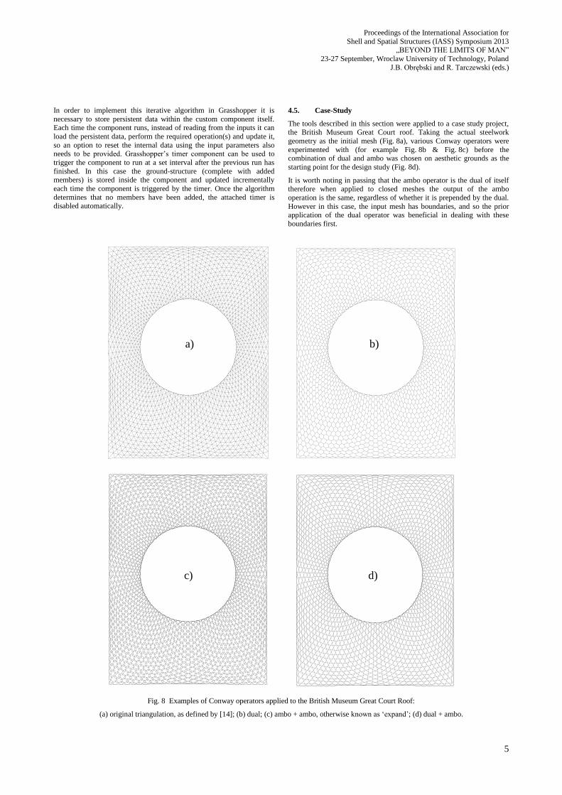
4.5. Case-Study
The tools described in this section were applied to a case study project, the British Museum Great Court roof. Taking the actual steelwork
geometry as the initial mesh (Fig. 8a), various Conway operators were
experimented with (for example Fig. 8b & Fig. 8c) before the combination of dual and ambo was chosen on aesthetic grounds as the
starting point for the design study (Fig. 8d).
It is worth noting in passing that the ambo operator is the dual of itself therefore when applied to closed meshes the output of the ambo
operation is the same, regardless of whether it is prepended by the dual.
However in this case, the input mesh has boundaries, and so the prior application of the dual operator was beneficial in dealing with these
boundaries first.
Fig. 8 Examples of Conway operators applied to the British Museum Great Court Roof:
(a) original triangulation, as defined by [14]; (b) dual; (c) ambo + ambo, otherwise known as ‘expand’; (d) dual + ambo.
a) b)
c) d)
6
The original triangular mesh was offset vertically below the new mesh
and inter-connected with a limiting distance of 2.8 units to produce the initial ground-structure containing 46,652 potential members (Fig. 9).
The same process was then applied again using a limit of 5 units to
produce a list of 136,712 potential new connections for the member-adding stage. Fully pinned supports were assigned to boundary vertices
of both layers and a uniformly distributed load was applied to the upper
layer, representing the cladding. An equal limiting stress was applied in both tension and compression, and joint-costs were not included.
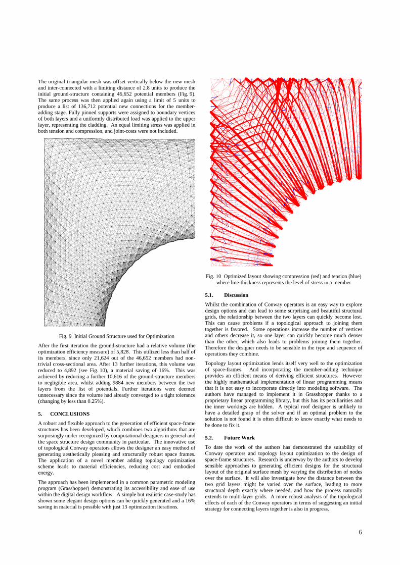
Fig. 9 Initial Ground Structure used for Optimization
After the first iteration the ground-structure had a relative volume (the
optimization efficiency measure) of 5,828. This utilized less than half of
its members, since only 21,624 out of the 46,652 members had non-trivial cross-sectional area. After 13 further iterations, this volume was
reduced to 4,892 (see Fig. 10), a material saving of 16%. This was
achieved by reducing a further 10,616 of the ground-structure members to negligible area, whilst adding 9884 new members between the two
layers from the list of potentials. Further iterations were deemed
unnecessary since the volume had already converged to a tight tolerance (changing by less than 0.25%).
5. CONCLUSIONS
A robust and flexible approach to the generation of efficient space-frame structures has been developed, which combines two algorithms that are
surprisingly under-recognized by computational designers in general and
the space structure design community in particular. The innovative use of topological Conway operators allows the designer an easy method of
generating aesthetically pleasing and structurally robust space frames.
The application of a novel member adding topology optimization scheme leads to material efficiencies, reducing cost and embodied
energy.
The approach has been implemented in a common parametric modeling program (Grasshopper) demonstrating its accessibility and ease of use
within the digital design workflow. A simple but realistic case-study has
shown some elegant design options can be quickly generated and a 16% saving in material is possible with just 13 optimization iterations.
Fig. 10 Optimized layout showing compression (red) and tension (blue)
where line-thickness represents the level of stress in a member
5.1. Discussion
Whilst the combination of Conway operators is an easy way to explore
design options and can lead to some surprising and beautiful structural grids, the relationship between the two layers can quickly become lost.
This can cause problems if a topological approach to joining them
together is favored. Some operations increase the number of vertices and others decrease it, so one layer can quickly become much denser
than the other, which also leads to problems joining them together.
Therefore the designer needs to be sensible in the type and sequence of operations they combine.
Topology layout optimization lends itself very well to the optimization
of space-frames. And incorporating the member-adding technique
provides an efficient means of deriving efficient structures. However
the highly mathematical implementation of linear programming means
that it is not easy to incorporate directly into modeling software. The authors have managed to implement it in Grasshopper thanks to a
proprietary linear programming library, but this has its peculiarities and
the inner workings are hidden. A typical roof designer is unlikely to have a detailed grasp of the solver and if an optimal problem to the
solution is not found it is often difficult to know exactly what needs to
be done to fix it.
5.2. Future Work
To date the work of the authors has demonstrated the suitability of
Conway operators and topology layout optimization to the design of space-frame structures. Research is underway by the authors to develop
sensible approaches to generating efficient designs for the structural layout of the original surface mesh by varying the distribution of nodes
over the surface. It will also investigate how the distance between the
two grid layers might be varied over the surface, leading to more structural depth exactly where needed, and how the process naturally
extends to multi-layer grids. A more robust analysis of the topological
effects of each of the Conway operators in terms of suggesting an initial strategy for connecting layers together is also in progress.

Proceedings of the International Association for
Shell and Spatial Structures (IASS) Symposium 2013 „BEYOND THE LIMITS OF MAN”
23-27 September, Wroclaw University of Technology, Poland
J.B. Obrębski and R. Tarczewski (eds.)
7
6. REFERENCES
[1] Shepherd, P. & Richens, P., The Case for Subdivision Surfaces in Building Design, J. IASS, 53(4), 2012, pp. 237-245.
[2] Conway, J. H., Burgiel, H. & Goodman-Strauss, C., The
Symmetries of Things, A K Peters Ltd, Wellesley, MA, 2008.
[3] Gilbert, M. & Tyas, A., Layout optimization of large-scale pin-
jointed frames, Engineering Computations, 20(8), 2003, pp1044-
1064. doi:10.1108/02644400310503017
[4] Chilton, J., Space Grid Structures, Architectural Press, Oxford,
2000, ISBN 978-0-7506-3275-5.
[5] Adriaenssens, S., Ney, L., Badarwe, E & Williams, C. , Dutch Maritime Museum: Form-finding of an irregular faceted skeletal
shell – Part b, in Domingo, A. & Lazaro, C. (eds), Proc. IASS
Symposium, Valencia, 2009, pp1356-1366. doi:10251/7078.
[6] Hart, G., Conway Notation for Polyhedra, Available online at
http://www.georgehart.com/virtual-
polyhedra/conway_notation.html, Accessed 30/05/2013.
[7] Topping, B. H. V., Shape Optimization of Skeletal Structures: A
Review, J. Struct. Eng., 109(8), 1983, pp1933-1951.
doi:10.1061/(ASCE)0733-9445(1983)109:8(1933).
[8] Darwich, W., Novel Computational Implementations for Ultimate
Limit State Analysis and Design, PhD Thesis, University of
Sheffield, (2010), Available online at http://www.wael.org/phd, Accessed 30/05/2013.
[9] Gilbert, M., Darwich, W., Tyas, A. & Shepherd, P., Application of Large-scale Layout Optimization Techniques in Structural
Engineering Practice, WCSMO6, Rio de Janeiro, 2005.
[10] McNeel, Grasshopper, Available online at
http://www.grasshopper3d.com/, Accessed 30/05/2013.
[11] Van Omme, N., Perron, L. & Furnon, V., OR-tools user's manual,
Google, 2013, Available online at http://code.google.com/p/or-tools/, Accessed 30/05/2013.
[12] Kettner, L., Using Generic Programming for Designing a Data
Structure for Polyhedral Surfaces, Computational Geometry Theory and Applications, 13(1), 1999, pp65-90.
doi:10.1016/S0925-7721(99)00007-3.
[13] Meagher, D., Geometric modeling using octree encoding, Computer Graphics and Image Processing, 19(2), 1982, pp129-
147. doi:10.1016/0146-664x(82)90104-6.
[14] Williams, C. J. K., The analytic and numerical definition of the geometry of the British Museum Great Court Roof, in Burry, M.,
Datta, S., Dawson, A. & Rollo, J., Proc. 3rd Int. Mathematics and
Design Conf., 2001, pp434-440. doi:10536/DRO/DU:30014976.


![DETECTION OF ALGORITHMICALLY GENERATED MALICIOUS … · of activity is evident in many cyber-crimes and it is well documented by various writers [16], [33], [47]. ... will then use](https://static.fdocuments.net/doc/165x107/6011252f45b52e38490d64f0/detection-of-algorithmically-generated-malicious-of-activity-is-evident-in-many.jpg)


