Topology Data Model and Network Data Model …...Oracle® Spatial and Graph Topology Data Model and...
394
Oracle® Spatial and Graph Topology Data Model and Network Data Model Graph Developer's Guide 19c E94802-01 January 2019
Transcript of Topology Data Model and Network Data Model …...Oracle® Spatial and Graph Topology Data Model and...

Oracle® Spatial and GraphTopology Data Model and Network DataModel Graph Developer's Guide
19cE94802-01January 2019

Oracle Spatial and Graph Topology Data Model and Network Data Model Graph Developer's Guide, 19c
E94802-01
Copyright © 2003, 2019, Oracle and/or its affiliates. All rights reserved.
Primary Author: Chuck Murray
Contributors: Ning An, Betsy George, Huiling Gong, Siva Ravada, Jack Wang
This software and related documentation are provided under a license agreement containing restrictions onuse and disclosure and are protected by intellectual property laws. Except as expressly permitted in yourlicense agreement or allowed by law, you may not use, copy, reproduce, translate, broadcast, modify,license, transmit, distribute, exhibit, perform, publish, or display any part, in any form, or by any means.Reverse engineering, disassembly, or decompilation of this software, unless required by law forinteroperability, is prohibited.
The information contained herein is subject to change without notice and is not warranted to be error-free. Ifyou find any errors, please report them to us in writing.
If this is software or related documentation that is delivered to the U.S. Government or anyone licensing it onbehalf of the U.S. Government, then the following notice is applicable:
U.S. GOVERNMENT END USERS: Oracle programs, including any operating system, integrated software,any programs installed on the hardware, and/or documentation, delivered to U.S. Government end users are"commercial computer software" pursuant to the applicable Federal Acquisition Regulation and agency-specific supplemental regulations. As such, use, duplication, disclosure, modification, and adaptation of theprograms, including any operating system, integrated software, any programs installed on the hardware,and/or documentation, shall be subject to license terms and license restrictions applicable to the programs.No other rights are granted to the U.S. Government.
This software or hardware is developed for general use in a variety of information management applications.It is not developed or intended for use in any inherently dangerous applications, including applications thatmay create a risk of personal injury. If you use this software or hardware in dangerous applications, then youshall be responsible to take all appropriate fail-safe, backup, redundancy, and other measures to ensure itssafe use. Oracle Corporation and its affiliates disclaim any liability for any damages caused by use of thissoftware or hardware in dangerous applications.
Oracle and Java are registered trademarks of Oracle and/or its affiliates. Other names may be trademarks oftheir respective owners.
Intel and Intel Xeon are trademarks or registered trademarks of Intel Corporation. All SPARC trademarks areused under license and are trademarks or registered trademarks of SPARC International, Inc. AMD, Opteron,the AMD logo, and the AMD Opteron logo are trademarks or registered trademarks of Advanced MicroDevices. UNIX is a registered trademark of The Open Group.
This software or hardware and documentation may provide access to or information about content, products,and services from third parties. Oracle Corporation and its affiliates are not responsible for and expresslydisclaim all warranties of any kind with respect to third-party content, products, and services unless otherwiseset forth in an applicable agreement between you and Oracle. Oracle Corporation and its affiliates will not beresponsible for any loss, costs, or damages incurred due to your access to or use of third-party content,products, or services, except as set forth in an applicable agreement between you and Oracle.
Contents
Preface
Audience xvi
Documentation Accessibility xvi
Related Documents xvi
Conventions xvi
Part I Topology Data Model
1 Topology Data Model Overview
1.1 Main Steps in Using Topology Data 1-2
1.1.1 Using a Topology Built from Topology Data 1-3
1.1.2 Using a Topology Built from Spatial Geometries 1-3
1.2 Topology Data Model Concepts 1-4
1.2.1 Tolerance in the Topology Data Model 1-7
1.3 Topology Geometries and Layers 1-8
1.3.1 Features 1-8
1.3.2 Collection Layers 1-9
1.4 Topology Geometry Layer Hierarchy 1-11
1.5 Topology Data Model Tables 1-14
1.5.1 Edge Information Table 1-15
1.5.2 Node Information Table 1-17
1.5.3 Face Information Table 1-18
1.5.4 Relationship Information Table 1-18
1.5.5 History Information Table 1-19
1.6 Topology Data Types 1-22
1.6.1 SDO_TOPO_GEOMETRY Type 1-22
1.6.2 SDO_TOPO_GEOMETRY Constructors 1-23
1.6.2.1 Constructors for Insert Operations: Specifying TopologicalElements 1-24
1.6.2.2 Constructors for Insert Operations: Specifying Lower-LevelFeatures 1-25
iii

1.6.2.3 Constructors for Update Operations: Specifying TopologicalElements 1-26
1.6.2.4 Constructors for Update Operations: Specifying Lower-LevelFeatures 1-27
1.6.3 GET_GEOMETRY Member Function 1-28
1.6.4 GET_TGL_OBJECTS Member Function 1-28
1.6.5 GET_TOPO_ELEMENTS Member Function 1-29
1.6.6 SDO_LIST_TYPE Type 1-29
1.6.7 SDO_EDGE_ARRAY and SDO_NUMBER_ARRAY Types 1-29
1.7 Topology Metadata Views 1-29
1.7.1 xxx_SDO_TOPO_INFO Views 1-30
1.7.2 xxx_SDO_TOPO_METADATA Views 1-31
1.8 Topology Application Programming Interface 1-33
1.8.1 Topology Operators 1-34
1.8.2 Topology Data Model Java Interface 1-37
1.9 Exporting and Importing Topology Data 1-37
1.10 Cross-Schema Topology Usage and Editing 1-38
1.10.1 Cross-Schema Topology Usage 1-39
1.10.2 Cross-Schema Topology Editing 1-39
1.11 Function-Based Indexes Not Supported 1-40
1.12 Topology Examples (PL/SQL) 1-40
1.12.1 Topology Built from Topology Data 1-40
1.12.2 Topology Built from Spatial Geometries 1-50
1.13 README File for Spatial and Graph and Related Features 1-55
2 Editing Topologies
2.1 Approaches for Editing Topology Data 2-1
2.1.1 TopoMap Objects 2-2
2.1.2 Specifying the Editing Approach with the Topology Parameter 2-3
2.1.3 Using GET_xxx Topology Functions 2-3
2.1.4 Process for Editing Using Cache Explicitly (PL/SQL API) 2-4
2.1.5 Process for Editing Using the Java API 2-6
2.1.6 Error Handling for Topology Editing 2-7
2.1.6.1 Input Parameter Errors 2-8
2.1.6.2 All Exceptions 2-8
2.2 Performing Operations on Nodes 2-9
2.2.1 Adding a Node 2-9
2.2.2 Moving a Node 2-11
2.2.2.1 Additional Examples of Allowed and Disallowed Node Moves 2-12
2.2.3 Removing a Node 2-13
2.2.4 Removing Obsolete Nodes 2-14
iv
2.3 Performing Operations on Edges 2-15
2.3.1 Adding an Edge 2-16
2.3.2 Moving an Edge 2-16
2.3.3 Removing an Edge 2-17
2.3.4 Updating an Edge 2-18
3 SDO_TOPO Package Subprograms
3.1 SDO_TOPO.ADD_TOPO_GEOMETRY_LAYER 3-1
3.2 SDO_TOPO.CREATE_TOPOLOGY 3-3
3.3 SDO_TOPO.DELETE_TOPO_GEOMETRY_LAYER 3-5
3.4 SDO_TOPO.DROP_TOPOLOGY 3-6
3.5 SDO_TOPO.GET_FACE_BOUNDARY 3-6
3.6 SDO_TOPO.GET_TOPO_OBJECTS 3-7
3.7 SDO_TOPO.INITIALIZE_AFTER_IMPORT 3-9
3.8 SDO_TOPO.INITIALIZE_METADATA 3-9
3.9 SDO_TOPO.PREPARE_FOR_EXPORT 3-10
3.10 SDO_TOPO.RELATE 3-11
4 SDO_TOPO_MAP Package Subprograms
4.1 SDO_TOPO_MAP.ADD_EDGE 4-2
4.2 SDO_TOPO_MAP.ADD_ISOLATED_NODE 4-4
4.3 SDO_TOPO_MAP.ADD_LINEAR_GEOMETRY 4-5
4.4 SDO_TOPO_MAP.ADD_LOOP 4-7
4.5 SDO_TOPO_MAP.ADD_NODE 4-8
4.6 SDO_TOPO_MAP.ADD_POINT_GEOMETRY 4-10
4.7 SDO_TOPO_MAP.ADD_POLYGON_GEOMETRY 4-11
4.8 SDO_TOPO_MAP.CHANGE_EDGE_COORDS 4-12
4.9 SDO_TOPO_MAP.CLEAR_TOPO_MAP 4-14
4.10 SDO_TOPO_MAP.COMMIT_TOPO_MAP 4-15
4.11 SDO_TOPO_MAP.CREATE_EDGE_INDEX 4-16
4.12 SDO_TOPO_MAP.CREATE_FACE_INDEX 4-16
4.13 SDO_TOPO_MAP.CREATE_FEATURE 4-17
4.14 SDO_TOPO_MAP.CREATE_TOPO_MAP 4-21
4.15 SDO_TOPO_MAP.DROP_TOPO_MAP 4-22
4.16 SDO_TOPO_MAP.GET_CONTAINING_FACE 4-23
4.17 SDO_TOPO_MAP.GET_EDGE_ADDITIONS 4-24
4.18 SDO_TOPO_MAP.GET_EDGE_CHANGES 4-25
4.19 SDO_TOPO_MAP.GET_EDGE_COORDS 4-25
4.20 SDO_TOPO_MAP.GET_EDGE_DELETIONS 4-26
v
4.21 SDO_TOPO_MAP.GET_EDGE_NODES 4-27
4.22 SDO_TOPO_MAP.GET_FACE_ADDITIONS 4-28
4.23 SDO_TOPO_MAP.GET_FACE_CHANGES 4-29
4.24 SDO_TOPO_MAP.GET_FACE_BOUNDARY 4-29
4.25 SDO_TOPO_MAP.GET_FACE_DELETIONS 4-30
4.26 SDO_TOPO_MAP.GET_NEAREST_EDGE 4-31
4.27 SDO_TOPO_MAP.GET_NEAREST_EDGE_IN_CACHE 4-32
4.28 SDO_TOPO_MAP.GET_NEAREST_NODE 4-33
4.29 SDO_TOPO_MAP.GET_NEAREST_NODE_IN_CACHE 4-35
4.30 SDO_TOPO_MAP.GET_NODE_ADDITIONS 4-36
4.31 SDO_TOPO_MAP.GET_NODE_CHANGES 4-36
4.32 SDO_TOPO_MAP.GET_NODE_COORD 4-37
4.33 SDO_TOPO_MAP.GET_NODE_DELETIONS 4-38
4.34 SDO_TOPO_MAP.GET_NODE_FACE_STAR 4-39
4.35 SDO_TOPO_MAP.GET_NODE_STAR 4-40
4.36 SDO_TOPO_MAP.GET_TOPO_NAME 4-41
4.37 SDO_TOPO_MAP.GET_TOPO_TRANSACTION_ID 4-41
4.38 SDO_TOPO_MAP.LIST_TOPO_MAPS 4-42
4.39 SDO_TOPO_MAP.LOAD_TOPO_MAP 4-43
4.40 SDO_TOPO_MAP.MOVE_EDGE 4-46
4.41 SDO_TOPO_MAP.MOVE_ISOLATED_NODE 4-48
4.42 SDO_TOPO_MAP.MOVE_NODE 4-49
4.43 SDO_TOPO_MAP.REMOVE_EDGE 4-51
4.44 SDO_TOPO_MAP.REMOVE_NODE 4-52
4.45 SDO_TOPO_MAP.REMOVE_OBSOLETE_NODES 4-52
4.46 SDO_TOPO_MAP.ROLLBACK_TOPO_MAP 4-53
4.47 SDO_TOPO_MAP.SEARCH_EDGE_RTREE_TOPO_MAP 4-54
4.48 SDO_TOPO_MAP.SEARCH_FACE_RTREE_TOPO_MAP 4-55
4.49 SDO_TOPO_MAP.SET_MAX_MEMORY_SIZE 4-56
4.50 SDO_TOPO_MAP.UPDATE_TOPO_MAP 4-56
4.51 SDO_TOPO_MAP.VALIDATE_TOPO_MAP 4-57
4.52 SDO_TOPO_MAP.VALIDATE_TOPOLOGY 4-59
Part II Network Data Model
5 Network Data Model Graph Overview
5.1 Introduction to Network Modeling 5-2
5.2 Main Steps in Using the Network Data Model Graph 5-3
5.2.1 Letting Spatial Perform Most Operations 5-4
5.2.2 Performing the Operations Yourself 5-5
vi

5.3 Network Data Model Graph Concepts 5-5
5.3.1 Subpaths 5-8
5.3.2 Features and Feature Layers 5-8
5.4 Network Applications 5-10
5.4.1 Road Network Example 5-10
5.4.2 Subway (Train) Network Example 5-11
5.4.3 Multimodal Network and Temporal Examples 5-11
5.4.4 Utility Network Example 5-11
5.4.5 Biochemical Network Example 5-12
5.5 Network Hierarchy 5-12
5.6 Network User Data 5-13
5.6.1 User-Defined Data Example (PL/SQL and Java) 5-14
5.6.2 User-Defined Data Example (Custom User Data I/O Implementation) 5-15
5.6.2.1 Implementation of writeUserData method of LODUserDataIO 5-16
5.6.2.2 Implementation of readUserData method of LODUserDataIO 5-17
5.7 Feature Modeling 5-19
5.7.1 Data Types Used for Feature Modeling 5-20
5.8 Feature Modeling Using Network Feature Editing (NFE) 5-20
5.8.1 Creation Modes for NFE Models 5-21
5.8.2 NFE Feature Classes 5-21
5.8.3 NFE Rules 5-22
5.8.4 Data Types Used for NFE Connectivity Rules 5-25
5.9 Network Constraints 5-26
5.10 Network Analysis Using Load on Demand 5-26
5.10.1 Partitioning a Network 5-27
5.10.2 Generating Partition BLOBs 5-27
5.10.3 Configuring the Partition Cache 5-28
5.10.4 Analyzing the Network 5-28
5.10.5 Using Link Levels for Priority Modeling 5-28
5.10.6 Precomputed Analysis Results 5-29
5.11 Network Data Model Graph Tables 5-29
5.11.1 Network Layer Tables 5-30
5.11.1.1 Node Table 5-30
5.11.1.2 Link Table 5-31
5.11.1.3 Path Table 5-32
5.11.1.4 Path-Link Table 5-33
5.11.1.5 Subpath Table 5-34
5.11.1.6 Partition Table 5-36
5.11.1.7 Partition BLOB Table 5-36
5.11.1.8 Connected Component Table 5-37
5.11.1.9 Node Hierarchy Table (Optional) 5-38
vii

5.11.1.10 Node Level Table (Optional) 5-39
5.11.2 Feature Layer Tables 5-39
5.11.2.1 Feature Table 5-39
5.11.2.2 Feature Element Relationships Table 5-40
5.11.2.3 Feature Hierarchy Table 5-40
5.11.3 Network Feature Editing (NFE) Model Tables 5-41
5.11.3.1 Automatically Created Points Default Attributes Table 5-42
5.11.3.2 Connectivity Line-Line Rules Table 5-42
5.11.3.3 Connectivity Line-Point Rules Table 5-43
5.11.3.4 Feature Class Table 5-44
5.11.3.5 Feature Class Attributes Constraints Table 5-44
5.11.3.6 Feature Class Default Predefined Connected Points Table 5-45
5.11.3.7 Feature Class Relationship Table 5-45
5.11.3.8 Feature Rule Relationship Table 5-46
5.11.3.9 Feature User Data Table 5-46
5.11.3.10 Feature User Data Catalog Table 5-47
5.11.3.11 Feature User Data Catalog Values Table 5-47
5.11.3.12 Point Cardinality Rules Table 5-48
5.11.3.13 Rule Decision Handlers Table 5-48
5.11.3.14 Rule Instance Table 5-50
5.12 Network Data Model Graph and Network Feature Editing (NFE) ModelMetadata Views 5-50
5.12.1 xxx_SDO_NETWORK_METADATA Views 5-51
5.12.2 xxx_SDO_NETWORK_CONSTRAINTS Views 5-55
5.12.3 xxx_SDO_NETWORK_USER_DATA Views 5-56
5.12.4 xxx_SDO_NETWORK_FEATURE Views 5-58
5.12.5 xxx_SDO_NFE_MODEL_FTLAYER_REL Views 5-59
5.12.6 xxx_SDO_NFE_MODEL_METADATA Views 5-60
5.12.7 xxx_SDO_NFE_MODEL_WORKSPACE Views 5-62
5.13 Network Data Model Graph Application Programming Interface 5-64
5.13.1 Network Data Model Graph PL/SQL Interface 5-64
5.13.2 Network Data Model Graph Java Interface 5-66
5.13.2.1 Network Metadata and Data Management 5-66
5.13.2.2 Network Analysis Using the Load on Demand Approach 5-66
5.13.3 Network Data Model Graph XML Interface 5-67
5.13.3.1 User-Specified Implementations 5-67
5.14 Cross-Schema Network Access 5-68
5.14.1 Cross-Schema Access by Specifying Owner in Network Metadata 5-69
5.14.2 Cross-Schema Access by Using Views 5-69
5.15 Network Examples 5-70
5.15.1 Simple Spatial (SDO) Network Example (PL/SQL) 5-71
viii
5.15.2 Simple Logical Network Example (PL/SQL) 5-73
5.15.3 Spatial (LRS) Network Example (PL/SQL) 5-74
5.15.4 Logical Hierarchical Network Example (PL/SQL) 5-81
5.15.5 Partitioning and Load on Demand Analysis Examples (PL/SQL, XML,and Java) 5-86
5.15.6 User-Defined Data Examples (PL/SQL and Java) 5-90
5.16 Network Data Model Graph Tutorial and Other Resources 5-94
5.17 README File for Spatial and Graph and Related Features 5-95
6 SDO_NET Package Subprograms
6.1 SDO_NET.ADD_CHILD_FEATURE 6-4
6.2 SDO_NET.ADD_CHILD_FEATURES 6-5
6.3 SDO_NET.ADD_FEATURE 6-6
6.4 SDO_NET.ADD_FEATURE_ELEMENT 6-7
6.5 SDO_NET.ADD_FEATURE_ELEMENTS 6-8
6.6 SDO_NET.ADD_FEATURE_LAYER 6-9
6.7 SDO_NET.COMPUTE_PATH_GEOMETRY 6-10
6.8 SDO_NET.COPY_NETWORK 6-11
6.9 SDO_NET.CREATE_LINK_TABLE 6-12
6.10 SDO_NET.CREATE_LOGICAL_NETWORK 6-13
6.11 SDO_NET.CREATE_LRS_NETWORK 6-15
6.12 SDO_NET.CREATE_LRS_TABLE 6-18
6.13 SDO_NET.CREATE_NODE_TABLE 6-19
6.14 SDO_NET.CREATE_PARTITION_TABLE 6-20
6.15 SDO_NET.CREATE_PATH_LINK_TABLE 6-21
6.16 SDO_NET.CREATE_PATH_TABLE 6-21
6.17 SDO_NET.CREATE_SDO_NETWORK 6-22
6.18 SDO_NET.CREATE_SUBPATH_TABLE 6-25
6.19 SDO_NET.CREATE_TOPO_NETWORK 6-26
6.20 SDO_NET.DELETE_CHILD_FEATURES 6-28
6.21 SDO_NET.DELETE_CHILD_FEATURES_AT 6-29
6.22 SDO_NET.DELETE_DANGLING_FEATURES 6-30
6.23 SDO_NET.DELETE_DANGLING_LINKS 6-31
6.24 SDO_NET.DELETE_DANGLING_NODES 6-31
6.25 SDO_NET.DELETE_FEATURE_ELEMENTS 6-32
6.26 SDO_NET.DELETE_FEATURE_ELEMENTS_AT 6-33
6.27 SDO_NET.DELETE_FEATURES 6-33
6.28 SDO_NET.DELETE_LINK 6-34
6.29 SDO_NET.DELETE_NODE 6-35
6.30 SDO_NET.DELETE_PATH 6-36
6.31 SDO_NET.DELETE_PHANTOM_FEATURES 6-36
ix
6.32 SDO_NET.DELETE_SUBPATH 6-37
6.33 SDO_NET.DEREGISTER_CONSTRAINT 6-37
6.34 SDO_NET.DROP_FEATURE_LAYER 6-38
6.35 SDO_NET.DROP_NETWORK 6-39
6.36 SDO_NET.FIND_CONNECTED_COMPONENTS 6-39
6.37 SDO_NET.GENERATE_NODE_LEVELS 6-40
6.38 SDO_NET.GENERATE_PARTITION_BLOB 6-42
6.39 SDO_NET.GENERATE_PARTITION_BLOBS 6-44
6.40 SDO_NET.GET_CHILD_FEATURE_IDS 6-46
6.41 SDO_NET.GET_CHILD_LINKS 6-47
6.42 SDO_NET.GET_CHILD_NODES 6-47
6.43 SDO_NET.GET_DANGLING_FEATURES 6-48
6.44 SDO_NET.GET_DANGLING_LINKS 6-49
6.45 SDO_NET.GET_DANGLING_NODES 6-49
6.46 SDO_NET.GET_FEATURE_ELEMENTS 6-50
6.47 SDO_NET.GET_FEATURE_LAYER_ID 6-51
6.48 SDO_NET.GET_FEATURES_ON_LINKS 6-51
6.49 SDO_NET.GET_FEATURES_ON_NODES 6-52
6.50 SDO_NET.GET_GEOMETRY_TYPE 6-53
6.51 SDO_NET.GET_IN_LINKS 6-54
6.52 SDO_NET.GET_INVALID_LINKS 6-54
6.53 SDO_NET.GET_INVALID_NODES 6-55
6.54 SDO_NET.GET_INVALID_PATHS 6-55
6.55 SDO_NET.GET_ISOLATED_NODES 6-56
6.56 SDO_NET.GET_LINK_COST_COLUMN 6-56
6.57 SDO_NET.GET_LINK_DIRECTION 6-57
6.58 SDO_NET.GET_LINK_GEOM_COLUMN 6-58
6.59 SDO_NET.GET_LINK_GEOMETRY 6-58
6.60 SDO_NET.GET_LINK_TABLE_NAME 6-59
6.61 SDO_NET.GET_LINKS_IN_PATH 6-60
6.62 SDO_NET.GET_LRS_GEOM_COLUMN 6-60
6.63 SDO_NET.GET_LRS_LINK_GEOMETRY 6-61
6.64 SDO_NET.GET_LRS_NODE_GEOMETRY 6-62
6.65 SDO_NET.GET_LRS_TABLE_NAME 6-62
6.66 SDO_NET.GET_NETWORK_TYPE 6-63
6.67 SDO_NET.GET_NO_OF_HIERARCHY_LEVELS 6-64
6.68 SDO_NET.GET_NO_OF_LINKS 6-64
6.69 SDO_NET.GET_NO_OF_NODES 6-65
6.70 SDO_NET.GET_NODE_DEGREE 6-66
6.71 SDO_NET.GET_NODE_GEOM_COLUMN 6-66
6.72 SDO_NET.GET_NODE_GEOMETRY 6-67
x
6.73 SDO_NET.GET_NODE_IN_DEGREE 6-68
6.74 SDO_NET.GET_NODE_OUT_DEGREE 6-68
6.75 SDO_NET.GET_NODE_TABLE_NAME 6-69
6.76 SDO_NET.GET_OUT_LINKS 6-70
6.77 SDO_NET.GET_PARENT_FEATURE_IDS 6-70
6.78 SDO_NET.GET_PARTITION_SIZE 6-71
6.79 SDO_NET.GET_PATH_GEOM_COLUMN 6-72
6.80 SDO_NET.GET_PATH_TABLE_NAME 6-73
6.81 SDO_NET.GET_PERCENTAGE 6-74
6.82 SDO_NET.GET_PHANTOM_FEATURES 6-75
6.83 SDO_NET.GET_PT 6-75
6.84 SDO_NET.IS_HIERARCHICAL 6-76
6.85 SDO_NET.IS_LINK_IN_PATH 6-77
6.86 SDO_NET.IS_LOGICAL 6-77
6.87 SDO_NET.IS_NODE_IN_PATH 6-78
6.88 SDO_NET.IS_SPATIAL 6-79
6.89 SDO_NET.LOAD_CONFIG 6-79
6.90 SDO_NET.LOGICAL_PARTITION 6-80
6.91 SDO_NET.LOGICAL_POWERLAW_PARTITION 6-82
6.92 SDO_NET.LRS_GEOMETRY_NETWORK 6-84
6.93 SDO_NET.NETWORK_EXISTS 6-85
6.94 SDO_NET.POST_XML 6-85
6.95 SDO_NET.REGISTER_CONSTRAINT 6-87
6.96 SDO_NET.SDO_GEOMETRY_NETWORK 6-88
6.97 SDO_NET.SET_LOGGING_LEVEL 6-89
6.98 SDO_NET.SET_MAX_JAVA_HEAP_SIZE 6-89
6.99 SDO_NET.SPATIAL_PARTITION 6-90
6.100 SDO_NET.TOPO_GEOMETRY_NETWORK 6-91
6.101 SDO_NET.UPDATE_FEATURE 6-92
6.102 SDO_NET.UPDATE_FEATURE_ELEMENT 6-93
6.103 SDO_NET.VALIDATE_LINK_SCHEMA 6-94
6.104 SDO_NET.VALIDATE_LRS_SCHEMA 6-95
6.105 SDO_NET.VALIDATE_NETWORK 6-95
6.106 SDO_NET.VALIDATE_NODE_SCHEMA 6-96
6.107 SDO_NET.VALIDATE_PARTITION_SCHEMA 6-97
6.108 SDO_NET.VALIDATE_PATH_SCHEMA 6-98
6.109 SDO_NET.VALIDATE_SUBPATH_SCHEMA 6-98
7 SDO_NFE Package Subprograms
7.1 SDO_NFE.APPLY_RULE 7-2
xi
7.2 SDO_NFE.CLASSIFY_LINES_BY_SIDE 7-2
7.3 SDO_NFE.CREATE_MODEL_SEQUENCE 7-4
7.4 SDO_NFE.CREATE_MODEL_STRUCTURE 7-4
7.5 SDO_NFE.CREATE_MODEL_UNDERLYING_NET 7-5
7.6 SDO_NFE.CREATE_MODEL_WORKSPACE 7-6
7.7 SDO_NFE.DELETE_ALL_FT_LAYERS 7-8
7.8 SDO_NFE.DELETE_ALL_WORKSPACES 7-8
7.9 SDO_NFE.DELETE_MODEL_STRUCTURE 7-9
7.10 SDO_NFE.DELETE_MODEL_WORKSPACE 7-9
7.11 SDO_NFE.DROP_MODEL_SEQUENCE 7-10
7.12 SDO_NFE.DROP_MODEL_UNDERLYING_NETWORK 7-10
7.13 SDO_NFE.GET_CONNECTION_POINT_GEOM 7-11
7.14 SDO_NFE.GET_INTERACTION_GROUPS 7-12
7.15 SDO_NFE.GET_LINES_MATCH_LP_RULE 7-13
7.16 SDO_NFE.GET_LL_CONN_INTERSECTIONS 7-14
7.17 SDO_NFE.GET_LP_CONN_INTERSECTIONS 7-15
7.18 SDO_NFE.GET_MODEL_SEQUENCE_NAME 7-17
7.19 SDO_NFE.GET_MODEL_TABLE_NAME 7-18
7.20 SDO_NFE.GET_MODEL_UNDERLYING_NETWORK 7-18
7.21 SDO_NFE.GET_NEXT_SEQUENCE_VALUE 7-19
7.22 SDO_NFE.GET_POINTS_MATCH_LP_RULE 7-20
7.23 SDO_NFE.IMPORT_NETWORK 7-21
7.24 SDO_NFE.SET_MODEL_UNDERLYING_NETWORK 7-22
Index
xii

List of Figures
1-1 Simplified Topology 1-5
1-2 Simplified Topology, with Grid Lines and Unit Numbers 1-7
1-3 Features in a Topology 1-9
1-4 Topology Geometry Layer Hierarchy 1-12
1-5 Mapping Between Feature Tables and Topology Tables 1-14
1-6 Nodes, Edges, and Faces 1-16
2-1 Editing Topologies Using the TopoMap Object Cache (PL/SQL API) 2-4
2-2 Editing Topologies Using the TopoMap Object Cache (Java API) 2-6
2-3 Adding a Non-Isolated Node 2-9
2-4 Effect of is_new_shape_point Value on Adding a Node 2-10
2-5 Topology Before Moving a Non-Isolated Node 2-11
2-6 Topology After Moving a Non-Isolated Node 2-11
2-7 Node Move Is Not Allowed 2-12
2-8 Topology for Node Movement Examples 2-13
2-9 Removing a Non-Isolated Node 2-14
2-10 Removing Obsolete Nodes 2-15
2-11 Adding a Non-Isolated Edge 2-16
2-12 Moving a Non-Isolated Edge 2-17
2-13 Removing a Non-Isolated Edge 2-18
4-1 Loading Topological Elements into a Window 4-45
5-1 San Francisco Nodes and Links 5-3
5-2 Path and Subpaths 5-8
5-3 Network Hierarchy 5-12
5-4 Simple Spatial (SDO) Network 5-71
5-5 Simple Logical Network 5-73
5-6 Roads and Road Segments for Spatial (LRS) Network Example 5-75
5-7 Nodes and Links for Logical Network Example 5-81
xiii
List of Tables
1-1 Columns in the <topology-name>_EDGE$ Table 1-15
1-2 Edge Table ID Column Values 1-17
1-3 Columns in the <topology-name>_NODE$ Table 1-17
1-4 Columns in the <topology-name>_FACE$ Table 1-18
1-5 Columns in the <topology-name>_RELATION$ Table 1-19
1-6 Columns in the <topology-name>_HISTORY$ Table 1-20
1-7 SDO_TOPO_GEOMETRY Type Attributes 1-22
1-8 Columns in the xxx_SDO_TOPO_INFO Views 1-30
1-9 Columns in the xxx_SDO_TOPO_METADATA Views 1-32
5-1 Feature Types 5-9
5-2 Feature Layer Types 5-9
5-3 Shapes for NFE Feature Classes 5-22
5-4 Examples of Line-Point Connectivity Rules 5-23
5-5 LHS and RHS for Sample Line-Line Rules 5-24
5-6 Node Table Columns 5-30
5-7 Link Table Columns 5-31
5-8 Path Table Columns 5-32
5-9 Path-Link Table Columns 5-33
5-10 Subpath Table Columns 5-34
5-11 Partition Table Columns 5-36
5-12 Partition BLOB Table Columns 5-37
5-13 Connected Component Table Columns 5-38
5-14 Node Hierarchy Table Columns 5-38
5-15 Node Level Table Columns 5-39
5-16 Feature Table Columns 5-39
5-17 Feature Element Relationships Table Columns 5-40
5-18 Feature Hierarchy Table Columns 5-40
5-19 Automatically Created Points Default Attributes Table Columns 5-42
5-20 Connectivity Line-Line Rules Table Columns 5-43
5-21 Connectivity Line-Point Rules Table Columns 5-43
5-22 Feature Class Table Columns 5-44
5-23 Feature Class Attributes Constraints Table Columns 5-45
5-24 Feature Class Default Predefined Connected Points Table Columns 5-45
5-25 Feature Class Relationship Table Columns 5-46
5-26 Feature Rule Relationship Table Columns 5-46
xiv
5-27 Feature User Data Table Columns 5-46
5-28 Feature User Data Catalog Table Columns 5-47
5-29 Feature User Data Catalog Values Table Columns 5-47
5-30 Point Cardinality Rules Table Columns 5-48
5-31 Rule Decision Handlers Table Columns 5-48
5-32 Rule Instance Table Columns 5-50
5-33 Columns in the xxx_SDO_NETWORK_METADATA Views 5-51
5-34 Columns in the xxx_SDO_NETWORK_CONSTRAINTS Views 5-55
5-35 Columns in the xxx_SDO_NETWORK_USER_DATA Views 5-56
5-36 Columns in the xxx_SDO_NETWORK_FEATURE Views 5-58
5-37 Columns in the xxx_SDO_NFE_MODEL_FTLAYER_REL Views 5-59
5-38 Columns in the xxx_SDO_NFE_MODEL_METADATA Views 5-60
5-39 Columns in the TABLE_REG_TAB Table 5-62
5-40 Columns in the SEQUENCE_REG_TAB Table 5-62
5-41 Columns in the xxx_SDO_NFE_MODEL_WORKSPACE Views 5-63
xv

Preface
Oracle Spatial and Graph Topology Data Model and Network Data Model GraphDeveloper's Guide provides usage and reference information about the Topology DataModel and Network Data Model Graph features of Oracle Spatial and Graph, which isoften referred to as just Spatial and Graph.
• Audience
• Documentation Accessibility
• Related Documents
• Conventions
AudienceThis guide is intended for those who need to work with data about nodes, edges, andfaces in a topology or nodes, links, and paths in a network.
You are assumed to be familiar with the main spatial concepts, data types, andoperations, as documented in Oracle Spatial and Graph Developer's Guide.
Documentation AccessibilityFor information about Oracle's commitment to accessibility, visit the OracleAccessibility Program website at http://www.oracle.com/pls/topic/lookup?ctx=acc&id=docacc.
Access to Oracle Support
Oracle customers that have purchased support have access to electronic supportthrough My Oracle Support. For information, visit http://www.oracle.com/pls/topic/lookup?ctx=acc&id=info or visit http://www.oracle.com/pls/topic/lookup?ctx=acc&id=trsif you are hearing impaired.
Related DocumentsFor more information, see Oracle Spatial and Graph Developer's Guide.
ConventionsThe following text conventions are used in this document:
Preface
xvi

Convention Meaning
boldface Boldface type indicates graphical user interface elements associatedwith an action, or terms defined in text or the glossary.
italic Italic type indicates book titles, emphasis, or placeholder variables forwhich you supply particular values.
monospace Monospace type indicates commands within a paragraph, URLs, codein examples, text that appears on the screen, or text that you enter.
Preface
xvii

Part ITopology Data Model
This part covers the topology data model feature of Oracle Spatial and Graph.
This document has two main parts:
• Part I provides conceptual, usage, and reference information about the TopologyData Model feature of Oracle Spatial and Graph.
• Network Data Model provides conceptual, usage, and reference information aboutthe Network Data Model Graph feature of Oracle Spatial and Graph.
Part I contains the following chapters:
• Topology Data Model OverviewThe Topology Data Model feature of Oracle Spatial and Graph lets you work withdata about nodes, edges, and faces in a topology.
• Editing TopologiesNode and edge data in a topology can be edited. The operations include adding,moving, and removing nodes and edges, and updating the coordinates of an edge.
• SDO_TOPO Package SubprogramsThe MDSYS.SDO_TOPO package contains subprograms (functions andprocedures) that constitute part of the PL/SQL application programming interface(API) for the Spatial and Graph Topology Data Model feature. This package mainlycontains subprograms for creating and managing topologies.
• SDO_TOPO_MAP Package SubprogramsThe MDSYS.SDO_TOPO_MAP package contains subprograms (functions andprocedures) that constitute part of the PL/SQL application programming interface(API) for the Spatial and Graph Topology Data Model feature.
1Topology Data Model Overview
The Topology Data Model feature of Oracle Spatial and Graph lets you work with dataabout nodes, edges, and faces in a topology.
For example, United States Census geographic data is provided in terms of nodes,chains, and polygons, and this data can be represented using the Spatial and GraphTopology Data Model feature. You can store information about topological elementsand geometry layers in Oracle Spatial and Graph tables and metadata views. You canthen perform certain spatial operations referencing the topological elements, forexample, finding which chains (such as streets) have any spatial interaction with aspecific polygon entity (such as a park).
This chapter describes the spatial data structures and data types that support theTopology Data Model feature, and what you need to do to populate and manipulatethe structures. You can use this information to write a program to convert yourtopological data into formats usable with Spatial and Graph.
Note:
Although this chapter discusses some topology terms as they relate toOracle Spatial and Graph, it assumes that you are familiar with basictopology concepts.
It also assumes that you are familiar with the main concepts, data types, andoperations as documented in Oracle Spatial and Graph Developer's Guide.
• Main Steps in Using Topology DataThis topic summarizes the main steps for working with topology data.
• Topology Data Model ConceptsTopology is a branch of mathematics concerned with objects in space. Topologicalrelationships include such relationships as contains, inside, covers, covered by,touch, and overlap with boundaries intersecting.
• Topology Geometries and LayersA topology geometry (also referred to as a feature) is a spatial representation ofa real world object. For example, Main Street and Walden State Park might be thenames of topology geometries.
• Topology Geometry Layer HierarchyIn some topologies, the topology geometry layers (feature layers) have one ormore parent-child relationships in a topology hierarchy. That is, the layer at thetopmost level consists of features in its child layer at the next level down in thehierarchy; the child layer might consist of features in its child layer at the next layerfarther down; and so on.
1-1

• Topology Data Model TablesTo use the Spatial and Graph topology capabilities, you must first insert data intospecial edge, node, and face tables, which are created by Spatial and Graph whenyou create a topology.
• Topology Data TypesThe main data type associated with the Topology Data Model isSDO_TOPO_GEOMETRY, which describes a topology geometry.
• Topology Metadata ViewsThere are two sets of topology metadata views for each schema (user):xxx_SDO_TOPO_INFO and xxx_SDO_TOPO_METADATA, where xxx can beUSER or ALL. These views are read-only to users; they are created andmaintained by Spatial and Graph.
• Topology Application Programming InterfaceThe Topology Data Model application programming interface (API) consists of thefollowing.
• Exporting and Importing Topology DataYou can export a topology from one database and import it into a new topologywith the same name, structures, and data in another database, as long as thetarget database does not already contain a topology with the same name as theexported topology.
• Cross-Schema Topology Usage and EditingThis topic contains requirements and guidelines for using and editing topologieswhen multiple database users (schemas) are involved.
• Function-Based Indexes Not SupportedYou cannot create a function-based index on a column of typeSDO_TOPO_GEOMETRY.
• Topology Examples (PL/SQL)This topic presents simplified PL/SQL examples that perform Topology DataModel operations.
• README File for Spatial and Graph and Related Features
1.1 Main Steps in Using Topology DataThis topic summarizes the main steps for working with topology data.
It refers to important concepts, structures, and operations that are described in detailin other topics.
The specific main steps depend on which of two basic approaches you follow, whichdepend on the kind of data you will use to build the topology:
• If you have data about the edges, nodes, and faces (but not spatial geometrydata), follow the steps in Using a Topology Built from Topology Data.
• If you will build the topology from spatial geometries that will become topologyfeatures, follow the steps in Using a Topology Built from Spatial Geometries.
You can use the Topology Data Model PL/SQL and Java APIs to update the topology(for example, to change the data about an edge, node, or face). The PL/SQL API formost editing operations is the SDO_TOPO_MAP package, which is documented in SDO_TOPO_MAP Package Subprograms. The Java API is described in TopologyData Model Java Interface.
Chapter 1Main Steps in Using Topology Data
1-2
• Using a Topology Built from Topology Data
• Using a Topology Built from Spatial Geometries
1.1.1 Using a Topology Built from Topology DataThe main steps for working with a topology built from topology data are as follows:
1. Create the topology, using the SDO_TOPO.CREATE_TOPOLOGY procedure.This causes the <topology-name>_EDGE$, <topology-name>_NODE$,<topology-name>_FACE$, and <topology-name>_HISTORY$ tables to becreated. (These tables are described in Edge Information Table, Node InformationTable, Face Information Table, and History Information Table, respectively.)
2. Load topology data into the node, edge, and face tables created in Step 1. This istypically done using a bulk-load utility, but it can be done using SQL INSERTstatements.
3. Create a feature table for each type of topology geometry layer in the topology.For example, a city data topology might have separate feature tables for landparcels, streets, and traffic signs.
4. Associate the feature tables with the topology, using the SDO_TOPO.ADD_TOPO_GEOMETRY_LAYER procedure for each feature table.This causes the <topology-name>_RELATION$ table to be created. (This table isdescribed in Relationship Information Table.)
5. Initialize topology metadata, using the SDO_TOPO.INITIALIZE_METADATAprocedure. (This procedure also creates spatial indexes on the <topology-name>_EDGE$, <topology-name>_NODE$, and <topology-name>_FACE$tables, and additional B-tree indexes on the <topology-name>_EDGE$ and<topology-name>_NODE$ tables.)
6. Load the feature tables using the SDO_TOPO_GEOMETRY constructor. (Thisconstructor is described in SDO_TOPO_GEOMETRY Constructors.)
7. Query the topology data (for example, using one of topology operators describedin Topology Operators).
8. Optionally, edit topology data using the PL/SQL or Java application programminginterfaces (APIs).
Topology Built from Topology Data contains a PL/SQL example that performs thesemain steps.
1.1.2 Using a Topology Built from Spatial GeometriesTo build a topology from spatial geometries, you must first perform the standardoperations for preparing data for use with Oracle Spatial and Graph, as described in Oracle Spatial and Graph Developer's Guide:
1. Create the spatial tables.
2. Update the spatial metadata (USER_SDO_GEOM_METADATA view).
3. Load data into the spatial tables.
4. Validate the spatial data.
5. Create the spatial indexes.
Chapter 1Main Steps in Using Topology Data
1-3
The main steps for working with a topology built from Oracle Spatial and Graphgeometries are as follows:
1. Create the topology, using the SDO_TOPO.CREATE_TOPOLOGY procedure.This causes the <topology-name>_EDGE$, <topology-name>_NODE$,<topology-name>_FACE$, and <topology-name>_HISTORY$ tables to becreated. (These tables are described in Edge Information Table, Node InformationTable, Face Information Table, and History Information Table, respectively.)
2. Create the universe face (F0, defined in Topology Data Model Concepts).
3. Create a feature table for each type of topology geometry layer in the topology.For example, a city data topology might have separate feature tables for landparcels, streets, and traffic signs.
4. Associate the feature tables with the topology, using the SDO_TOPO.ADD_TOPO_GEOMETRY_LAYER procedure for each feature table.This causes the <topology-name>_RELATION$ table to be created. (This table isdescribed in Relationship Information Table.)
5. Initialize topology metadata, using the SDO_TOPO.INITIALIZE_METADATAprocedure. (This procedure also creates spatial indexes on the <topology-name>_EDGE$, <topology-name>_NODE$, and <topology-name>_FACE$tables, and additional B-tree indexes on the <topology-name>_EDGE$ and<topology-name>_NODE$ tables.)
6. Create a TopoMap object and load the whole topology into cache.
7. Load the feature tables, inserting data from the spatial tables and using the SDO_TOPO_MAP.CREATE_FEATURE function.
8. Query the topology data (using one of topology operators described in TopologyOperators).
9. Optionally, edit topology data using the PL/SQL or Java application programminginterfaces (APIs).
Topology Built from Spatial Geometries contains a PL/SQL example that performsthese main steps.
1.2 Topology Data Model ConceptsTopology is a branch of mathematics concerned with objects in space. Topologicalrelationships include such relationships as contains, inside, covers, covered by, touch,and overlap with boundaries intersecting.
Topological relationships remain constant when the coordinate space is deformed,such as by twisting or stretching. (Examples of relationships that are not topologicalinclude length of, distance between, and area of.)
The basic elements in a topology are its nodes, edges, and faces.
A node, represented by a point, can be isolated or it can be used to bound edges.Two or more edges meet at a non-isolated node. A node has a coordinate pairassociated with it that describes the spatial location for that node. Examples ofgeographic entities that might be represented as nodes include start and end points ofstreets, places of historical interest, and airports (if the map scale is sufficiently large).
An edge is bounded by two nodes: the start (origin) node and the end (terminal) node.An edge has an associated geometric object, usually a coordinate string that describes
Chapter 1Topology Data Model Concepts
1-4
the spatial representation of the edge. An edge may have several vertices making up aline string. (Circular arcs are not supported for topologies.) Examples of geographicentities that might be represented as edges include segments of streets and rivers.
The order of the coordinates gives a direction to an edge, and direction is important indetermining topological relationships. The positive direction agrees with the orientationof the underlying edge, and the negative direction reverses this orientation. Eachorientation of an edge is referred to as a directed edge, and each directed edge is themirror image of its other directed edge. The start node of the positive directed edge isthe end node of the negative directed edge. An edge also lies between two faces andhas references to both of them. Each directed edge contains a reference to the nextedge in the contiguous perimeter of the face on its left side.A face, corresponding to apolygon, has a reference to one directed edge of its outer boundary. If any islandnodes or island edges are present, the face also has a reference to one directed edgeon the boundary of each island. Examples of geographic entities that might berepresented as faces include parks, lakes, counties, and states.
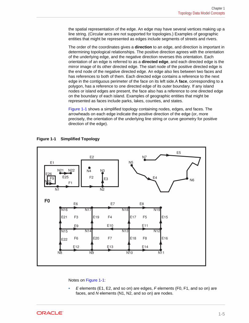
Figure 1-1 shows a simplified topology containing nodes, edges, and faces. Thearrowheads on each edge indicate the positive direction of the edge (or, moreprecisely, the orientation of the underlying line string or curve geometry for positivedirection of the edge).
Figure 1-1 Simplified Topology
E1
N1
E25
N3N4
N2
F5
N18
F7
N14
F6
E3
N22N21
F8
N13
E4
F3
N19
F4
F2
N16 N17
E21
N8 N10N9 N11
N12N15
F0
E22
E12 E13
E2
F1
E14
E19
E20
E17
E18
N5
N6
N7
E9
E8E6
E5
E7
E10 E11
E15
E16
N20F9
E26
Notes on Figure 1-1:
• E elements (E1, E2, and so on) are edges, F elements (F0, F1, and so on) arefaces, and N elements (N1, N2, and so on) are nodes.
Chapter 1Topology Data Model Concepts
1-5

• F0 (face zero) is created for every topology. It is the universe face containingeverything else in the topology. There is no geometry associated with the universeface. F0 has the face ID value of -1 (negative 1).
• There is a node created for every point geometry and for every start and end nodeof an edge. For example, face F1 has only an edge (a closed edge), E1, that hasthe same node as the start and end nodes (N1). F1 also has edge E25, with startnode N21 and end node N22.
• An isolated node (also called an island node) is a node that is isolated in a face.For example, node N4 is an isolated node in face F2.
• An isolated edge (also called an island edge) is an edge that is isolated in aface. For example, edge E25 is an isolated edge in face F1.
• A loop edge is an edge that has the same node as its start node and end node.For example, edge E1 is a loop edge starting and ending at node N1.
• An edge cannot have an isolated (island) node on it. The edge can be broken upinto two edges by adding a node on the edge. For example, if there was originallya single edge between nodes N16 and N18, adding node N17 resulted in twoedges: E6 and E7.
• Information about the topological relationships is stored in special edge, face, andnode information tables. For example, the edge information table contains thefollowing information about edges E9 and E10. (Note the direction of thearrowheads for each edge.) The next and previous edges are based on the leftand right faces of the edge.
For edge E9, the start node is N15 and the end node is N14, the next left edge isE19 and the previous left edge is -E21, the next right edge is -E22 and theprevious right edge is E20, the left face is F3 and the right face is F6.
For edge E10, the start node is N13 and the end node is N14, the next left edge is-E20 and the previous left edge is E18, the next right edge is E17 and the previousright edge is -E19, the left face is F7 and the right face is F4.
For additional examples of edge-related data, including an illustration andexplanations, see Edge Information Table.
Figure 1-2 shows the same topology illustrated in Figure 1-1, but it adds a grid and unitnumbers along the x-axis and y-axis. Figure 1-2 is useful for understanding the outputof some of the examples in SDO_TOPO Package Subprograms and SDO_TOPO_MAP Package Subprograms.
Chapter 1Topology Data Model Concepts
1-6
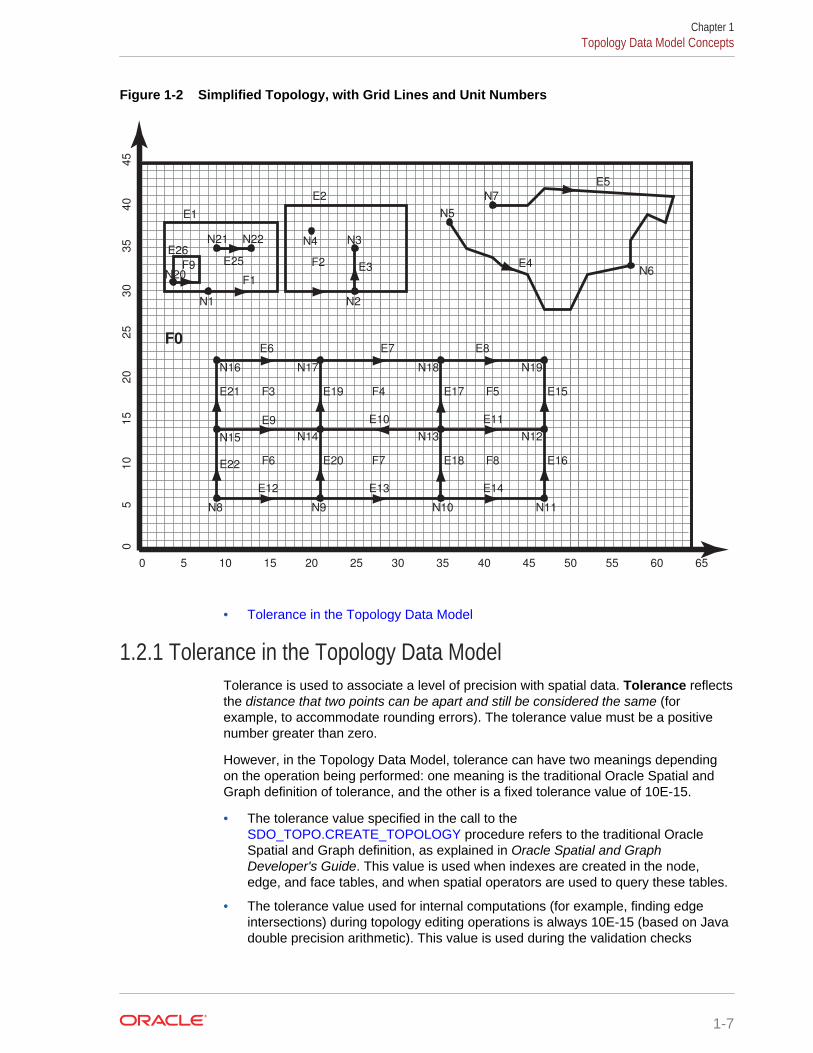
Figure 1-2 Simplified Topology, with Grid Lines and Unit Numbers
0 5 10 15 20 25 30 35 40 45 50 55 60 65
0
5
10
1
5
2
0
25
30
3
5
4
0
45
E1
N1
E25
N3N4
N2
F5
N18
F7
N14
F6
E3
N22N21
F8
N13
E4
F3
N19
F4
F2
N16 N17
E21
N8 N10N9 N11
N12N15
F0
E22
E12 E13
E2
F1
E14
E19
E20
E17
E18
N5
N6
N7
E9
E8E6
E5
E7
E10 E11
E15
E16
N20F9
E26
• Tolerance in the Topology Data Model
1.2.1 Tolerance in the Topology Data ModelTolerance is used to associate a level of precision with spatial data. Tolerance reflectsthe distance that two points can be apart and still be considered the same (forexample, to accommodate rounding errors). The tolerance value must be a positivenumber greater than zero.
However, in the Topology Data Model, tolerance can have two meanings dependingon the operation being performed: one meaning is the traditional Oracle Spatial andGraph definition of tolerance, and the other is a fixed tolerance value of 10E-15.
• The tolerance value specified in the call to the SDO_TOPO.CREATE_TOPOLOGY procedure refers to the traditional OracleSpatial and Graph definition, as explained in Oracle Spatial and GraphDeveloper's Guide. This value is used when indexes are created in the node,edge, and face tables, and when spatial operators are used to query these tables.
• The tolerance value used for internal computations (for example, finding edgeintersections) during topology editing operations is always 10E-15 (based on Javadouble precision arithmetic). This value is used during the validation checks
Chapter 1Topology Data Model Concepts
1-7

performed by the SDO_TOPO_MAP.VALIDATE_TOPO_MAP and SDO_TOPO_MAP.VALIDATE_TOPOLOGY functions.
Thus, for example, an edge geometry that is considered valid by the SDO_TOPO_MAP.VALIDATE_TOPO_MAP or SDO_TOPO_MAP.VALIDATE_TOPOLOGY function might not be valid if thatgeometry is passed to the SDO_GEOM.VALIDATE_GEOMETRY_WITH_CONTEXTfunction.
1.3 Topology Geometries and LayersA topology geometry (also referred to as a feature) is a spatial representation of areal world object. For example, Main Street and Walden State Park might be thenames of topology geometries.
The geometry is stored as a set of topological elements (nodes, edges, and faces),which are sometimes also referred to as primitives. Each topology geometry has aunique ID (assigned by Spatial and Graph when records are imported or loaded)associated with it.
A topology geometry layer consists of topology geometries, usually of a specifictopology geometry type, although it can be a collection of multiple types (see Collection Layers for information about collection layers). For example, Streets mightbe the topology geometry layer that includes the Main Street topology geometry, andState Parks might be the topology geometry layer that includes the Walden State Parktopology geometry. Each topology geometry layer has a unique ID (assigned bySpatial and Graph) associated with it. The data for each topology geometry layer isstored in a feature table. For example, a feature table named CITY_STREETS mightcontain information about all topology geometries (individual roads or streets) in theStreets topology geometry layer.
Each topology geometry (feature) is defined as an object of typeSDO_TOPO_GEOMETRY (described in SDO_TOPO_GEOMETRY Type), whichidentifies the topology geometry type, topology geometry ID, topology geometry layerID, and topology ID for the topology.
Topology metadata is automatically maintained by Spatial and Graph in theUSER_SDO_TOPO_METADATA and ALL_SDO_TOPO_METADATA views, whichare described in xxx_SDO_TOPO_METADATA Views. The USER_SDO_TOPO_INFOand ALL_SDO_TOPO_INFO views (described in xxx_SDO_TOPO_INFO Views)contain a subset of this topology metadata.
• Features
• Collection Layers
1.3.1 FeaturesOften, there are fewer features in a topology than there are topological elements(nodes, edges, and faces). For example, a road feature may consist of many edges,an area feature such as a park may consist of many faces, and some nodes may notbe associated with point features. Figure 1-3 shows point, line, and area featuresassociated with the topology that was shown in Figure 1-1 in Topology Data ModelConcepts.
Chapter 1Topology Geometries and Layers
1-8
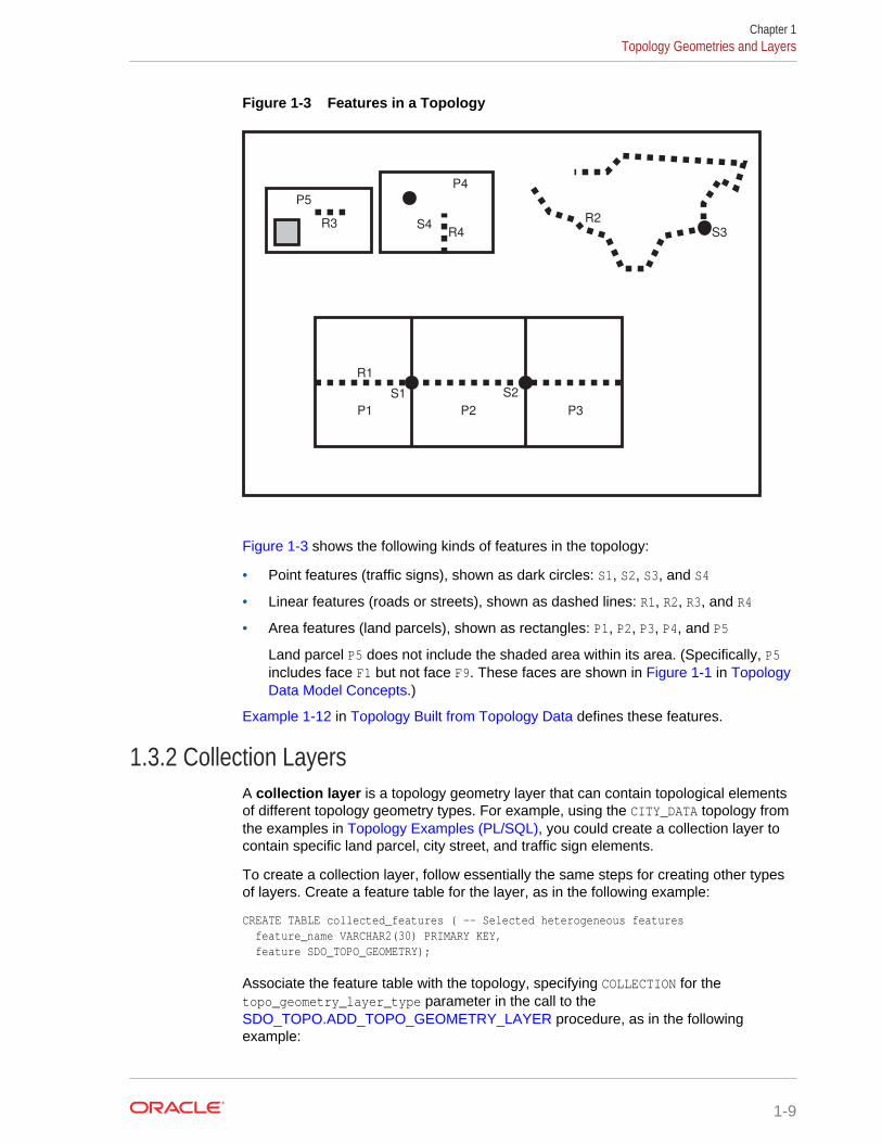
Figure 1-3 Features in a Topology
R3 S4
P2P1
R4
P3
P4
P5
R2
S3
S1 S2
R1
Figure 1-3 shows the following kinds of features in the topology:
• Point features (traffic signs), shown as dark circles: S1, S2, S3, and S4
• Linear features (roads or streets), shown as dashed lines: R1, R2, R3, and R4
• Area features (land parcels), shown as rectangles: P1, P2, P3, P4, and P5
Land parcel P5 does not include the shaded area within its area. (Specifically, P5includes face F1 but not face F9. These faces are shown in Figure 1-1 in TopologyData Model Concepts.)
Example 1-12 in Topology Built from Topology Data defines these features.
1.3.2 Collection LayersA collection layer is a topology geometry layer that can contain topological elementsof different topology geometry types. For example, using the CITY_DATA topology fromthe examples in Topology Examples (PL/SQL), you could create a collection layer tocontain specific land parcel, city street, and traffic sign elements.
To create a collection layer, follow essentially the same steps for creating other typesof layers. Create a feature table for the layer, as in the following example:
CREATE TABLE collected_features ( -- Selected heterogeneous features feature_name VARCHAR2(30) PRIMARY KEY, feature SDO_TOPO_GEOMETRY);
Associate the feature table with the topology, specifying COLLECTION for thetopo_geometry_layer_type parameter in the call to the SDO_TOPO.ADD_TOPO_GEOMETRY_LAYER procedure, as in the followingexample:
Chapter 1Topology Geometries and Layers
1-9
EXECUTE SDO_TOPO.ADD_TOPO_GEOMETRY_LAYER('CITY_DATA', COLLECTED_FEATURES', 'FEATURE', 'COLLECTION');
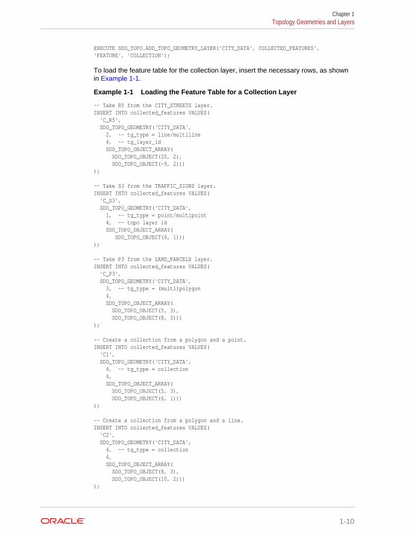
To load the feature table for the collection layer, insert the necessary rows, as shownin Example 1-1.
Example 1-1 Loading the Feature Table for a Collection Layer
-- Take R5 from the CITY_STREETS layer.INSERT INTO collected_features VALUES( 'C_R5', SDO_TOPO_GEOMETRY('CITY_DATA', 2, -- tg_type = line/multiline 4, -- tg_layer_id SDO_TOPO_OBJECT_ARRAY( SDO_TOPO_OBJECT(20, 2), SDO_TOPO_OBJECT(-9, 2)))); -- Take S3 from the TRAFFIC_SIGNS layer.INSERT INTO collected_features VALUES( 'C_S3', SDO_TOPO_GEOMETRY('CITY_DATA', 1, -- tg_type = point/multipoint 4, -- topo layer id SDO_TOPO_OBJECT_ARRAY( SDO_TOPO_OBJECT(6, 1)))); -- Take P3 from the LAND_PARCELS layer.INSERT INTO collected_features VALUES( 'C_P3', SDO_TOPO_GEOMETRY('CITY_DATA', 3, -- tg_type = (multi)polygon 4, SDO_TOPO_OBJECT_ARRAY( SDO_TOPO_OBJECT(5, 3), SDO_TOPO_OBJECT(8, 3)))); -- Create a collection from a polygon and a point.INSERT INTO collected_features VALUES( 'C1', SDO_TOPO_GEOMETRY('CITY_DATA', 4, -- tg_type = collection 4, SDO_TOPO_OBJECT_ARRAY( SDO_TOPO_OBJECT(5, 3), SDO_TOPO_OBJECT(6, 1)))); -- Create a collection from a polygon and a line.INSERT INTO collected_features VALUES( 'C2', SDO_TOPO_GEOMETRY('CITY_DATA', 4, -- tg_type = collection 4, SDO_TOPO_OBJECT_ARRAY( SDO_TOPO_OBJECT(8, 3), SDO_TOPO_OBJECT(10, 2))));
Chapter 1Topology Geometries and Layers
1-10
-- Create a collection from a line and a point.INSERT INTO collected_features VALUES( 'C3', SDO_TOPO_GEOMETRY('CITY_DATA', 4, -- tg_type = collection 4, SDO_TOPO_OBJECT_ARRAY( SDO_TOPO_OBJECT(-5, 2), SDO_TOPO_OBJECT(10, 1))));
1.4 Topology Geometry Layer HierarchyIn some topologies, the topology geometry layers (feature layers) have one or moreparent-child relationships in a topology hierarchy. That is, the layer at the topmostlevel consists of features in its child layer at the next level down in the hierarchy; thechild layer might consist of features in its child layer at the next layer farther down; andso on.
For example, a land use topology might have the following topology geometry layers atdifferent levels of hierarchy:
• States at the highest level, which consists of features from its child layer, Counties
• Counties at the next level down, which consists of features from its child layer,Tracts
• Tracts at the next level down, which consists of features from its child layer, BlockGroups
• Block Groups at the next level down, which consists of features from its child layer,Land Parcels
• Land Parcels at the lowest level of the hierarchy
If the topology geometry layers in a topology have this hierarchical relationship, it is farmore efficient if you model the layers as hierarchical than if you specify all topologygeometry layers at a single level (that is, with no hierarchy). For example, it is moreefficient to construct SDO_TOPO_GEOMETRY objects for counties by specifying onlythe tracts in the county than by specifying all land parcels in all block groups in alltracts in the county.
The lowest level (for the topology geometry layer containing the smallest kinds offeatures) in a hierarchy is level 0, and successive higher levels are numbered 1, 2, andso on. Topology geometry layers at adjacent levels of a hierarchy have a parent-childrelationship. Each topology geometry layer at the higher level is the parent layer forone layer at the lower level, which is its child layer. A parent layer can have only onechild layer, but a child layer can have one or more parent layers. Using the precedingexample, the Counties layer can have only one child layer, Tracts; however, the Tractslayer could have parent layers named Counties and Water Districts.
Chapter 1Topology Geometry Layer Hierarchy
1-11
Note:
Topology geometry layer hierarchy is somewhat similar to network hierarchy,which is described in Network Hierarchy; however, there are significantdifferences, and you should not confuse the two. For example, the lowesttopology geometry layer hierarchy level is 0, and the lowest networkhierarchy level is 1; and in a topology geometry layer hierarchy each parentmust have one child and each child can have many parents, while in anetwork hierarchy each parent can have many children and each child musthave one parent.
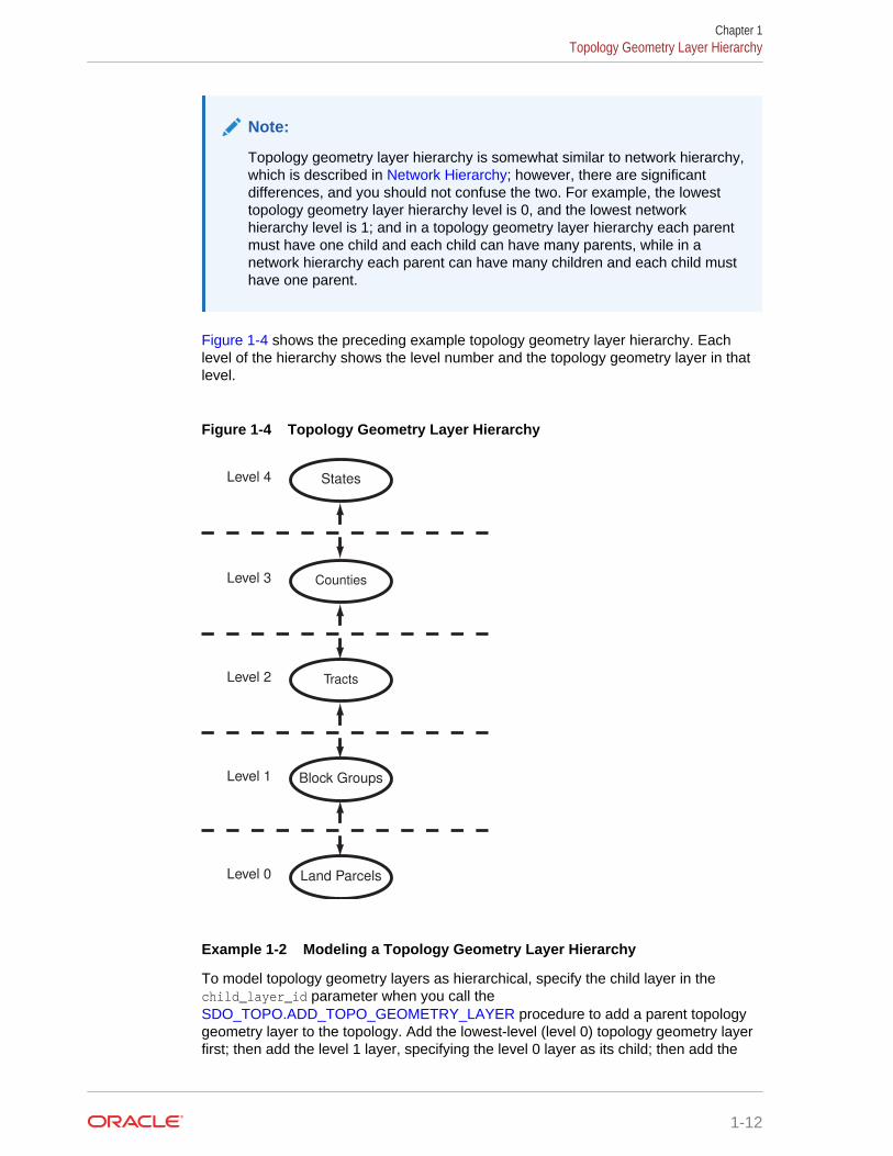
Figure 1-4 shows the preceding example topology geometry layer hierarchy. Eachlevel of the hierarchy shows the level number and the topology geometry layer in thatlevel.
Figure 1-4 Topology Geometry Layer Hierarchy
Level 0 Land Parcels
Level 1 Block Groups
Level 2 Tracts
Level 3 Counties
Level 4 States
Example 1-2 Modeling a Topology Geometry Layer Hierarchy
To model topology geometry layers as hierarchical, specify the child layer in thechild_layer_id parameter when you call the SDO_TOPO.ADD_TOPO_GEOMETRY_LAYER procedure to add a parent topologygeometry layer to the topology. Add the lowest-level (level 0) topology geometry layerfirst; then add the level 1 layer, specifying the level 0 layer as its child; then add the
Chapter 1Topology Geometry Layer Hierarchy
1-12
level 2 layer, specifying the level 1 layer as its child; and so on. Example 1-2 showsfive topology geometry layers being added so that the 5-level hierarchy is established.
-- Create the topology. (Null SRID in this example.)EXECUTE SDO_TOPO.CREATE_TOPOLOGY('LAND_USE_HIER', 0.00005); -- Create feature tables.CREATE TABLE land_parcels ( -- Land parcels (selected faces) feature_name VARCHAR2(30) PRIMARY KEY, feature SDO_TOPO_GEOMETRY); CREATE TABLE block_groups ( feature_name VARCHAR2(30) PRIMARY KEY, feature SDO_TOPO_GEOMETRY); CREATE TABLE tracts ( feature_name VARCHAR2(30) PRIMARY KEY, feature SDO_TOPO_GEOMETRY); CREATE TABLE counties ( feature_name VARCHAR2(30) PRIMARY KEY, feature SDO_TOPO_GEOMETRY); CREATE TABLE states ( feature_name VARCHAR2(30) PRIMARY KEY, feature SDO_TOPO_GEOMETRY); -- (Other steps not shown here, such as populating the feature tables-- and initializing the metadata.). . .-- Associate feature tables with the topology; include hierarchy information.
DECLARE land_parcels_id NUMBER; block_groups_id NUMBER; tracts_id NUMBER; counties_id NUMBER;BEGINSDO_TOPO.ADD_TOPO_GEOMETRY_LAYER('LAND_USE_HIER', 'LAND_PARCELS', 'FEATURE','POLYGON');SELECT tg_layer_id INTO land_parcels_id FROM user_sdo_topo_info WHERE topology = 'LAND_USE_HIER' AND table_name = 'LAND_PARCELS';SDO_TOPO.ADD_TOPO_GEOMETRY_LAYER('LAND_USE_HIER', 'BLOCK_GROUPS', 'FEATURE','POLYGON', NULL, land_parcels_id);SELECT tg_layer_id INTO block_groups_id FROM user_sdo_topo_info WHERE topology = 'LAND_USE_HIER' AND table_name = 'BLOCK_GROUPS';SDO_TOPO.ADD_TOPO_GEOMETRY_LAYER('LAND_USE_HIER', 'TRACTS', 'FEATURE','POLYGON', NULL, block_groups_id);SELECT tg_layer_id INTO tracts_id FROM user_sdo_topo_info WHERE topology = 'LAND_USE_HIER' AND table_name = 'TRACTS';SDO_TOPO.ADD_TOPO_GEOMETRY_LAYER('LAND_USE_HIER', 'COUNTIES', 'FEATURE','POLYGON', NULL, tracts_id);SELECT tg_layer_id INTO counties_id FROM user_sdo_topo_info WHERE topology = 'LAND_USE_HIER' AND table_name = 'COUNTIES';SDO_TOPO.ADD_TOPO_GEOMETRY_LAYER('LAND_USE_HIER', 'STATES', 'FEATURE','POLYGON', NULL, counties_id);END;/
Within each level above level 0, each layer can contain features built from features atthe next lower level (as is done in Example 1-2), features built from topologicalelements (faces, nodes, edges), or a combination of these. For example, a tracts layer
Chapter 1Topology Geometry Layer Hierarchy
1-13
can contain tracts built from block groups or tracts built from faces, or both. However,each feature within the layer must be built only either from features from the next lowerlevel or from topological elements. For example, a specific tract can consist of blockgroups or it can consist of faces, but it cannot consist of a combination of block groupsand faces.
To insert or update topology geometry objects in feature tables for the levels in ahierarchy, use the appropriate forms of the SDO_TOPO_GEOMETRY constructor.Feature tables are described in Topology Geometries and Layers, andSDO_TOPO_GEOMETRY constructors are described in SDO_TOPO_GEOMETRYConstructors.
Note that the TOPO_ID and TOPO_TYPE attributes in the relationship informationtable have special meanings when applied to parent layers in a topology with atopology geometry layer hierarchy. See the explanations of these attributes in Table 1-5 in Relationship Information Table.
1.5 Topology Data Model TablesTo use the Spatial and Graph topology capabilities, you must first insert data intospecial edge, node, and face tables, which are created by Spatial and Graph whenyou create a topology.
The edge, node, and face tables are described in Edge Information Table, NodeInformation Table, and Face Information Table, respectively.
Spatial and Graph automatically maintains a relationship information (<topology-name>_RELATION$) table for each topology, which is created the first time that afeature table is associated with a topology (that is, at the first call to the SDO_TOPO.ADD_TOPO_GEOMETRY_LAYER procedure that specifies thetopology). The relationship information table is described in Relationship InformationTable.
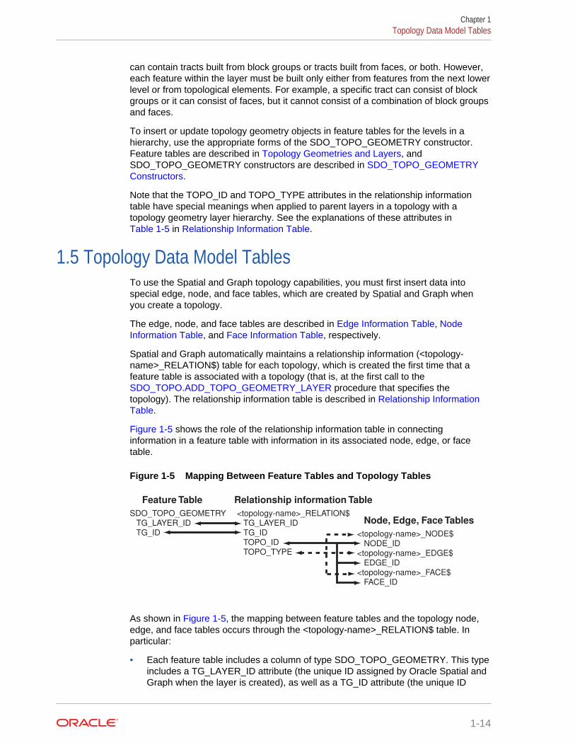
Figure 1-5 shows the role of the relationship information table in connectinginformation in a feature table with information in its associated node, edge, or facetable.
Figure 1-5 Mapping Between Feature Tables and Topology Tables
SDO_TOPO_GEOMETRY TG_LAYER_ID TG_ID
<topology-name>_RELATION$ TG_LAYER_ID TG_ID TOPO_ID TOPO_TYPE
<topology-name>_NODE$ NODE_ID <topology-name>_EDGE$ EDGE_ID <topology-name>_FACE$ FACE_ID
Feature Table Relationship information Table
Node, Edge, Face Tables
As shown in Figure 1-5, the mapping between feature tables and the topology node,edge, and face tables occurs through the <topology-name>_RELATION$ table. Inparticular:
• Each feature table includes a column of type SDO_TOPO_GEOMETRY. This typeincludes a TG_LAYER_ID attribute (the unique ID assigned by Oracle Spatial andGraph when the layer is created), as well as a TG_ID attribute (the unique ID
Chapter 1Topology Data Model Tables
1-14
assigned to each feature in a layer). The values in these two columns havecorresponding values in the TG_LAYER_ID and TG_ID columns in the <topology-name>_RELATION$ table.
• Each feature has one or more rows in the <topology-name>_RELATION$ table.
• Given the TG_LAYER_ID and TG_ID values for a feature, the set of nodes, faces,and edges associated with the feature can be determined by matching theTOPO_ID value (the node, edge, or face ID) in the <topology-name>_RELATION$table with the corresponding ID value in the <topology-name>_NODE$, <topology-name>_EDGE$, or <topology-name>_FACE$ table.
The following considerations apply to schema, table, and column names that arestored in any Oracle Spatial and Graph metadata views. For example, theseconsiderations apply to the names of edge, node, face, relationship, and historyinformation tables, and to the names of any columns in these tables and schemas forthese tables that are stored in the topology metadata views described in TopologyMetadata Views.
• The name must contain only letters, numbers, and underscores. For example, thename cannot contain a space ( ), an apostrophe ('), a quotation mark ("), or acomma (,).
• All letters in the names are converted to uppercase before the names are stored inmetadata views or before the tables are accessed. This conversion also applies toany schema name specified with the table name.
• Edge Information Table
• Node Information Table
• Face Information Table
• Relationship Information Table
• History Information Table
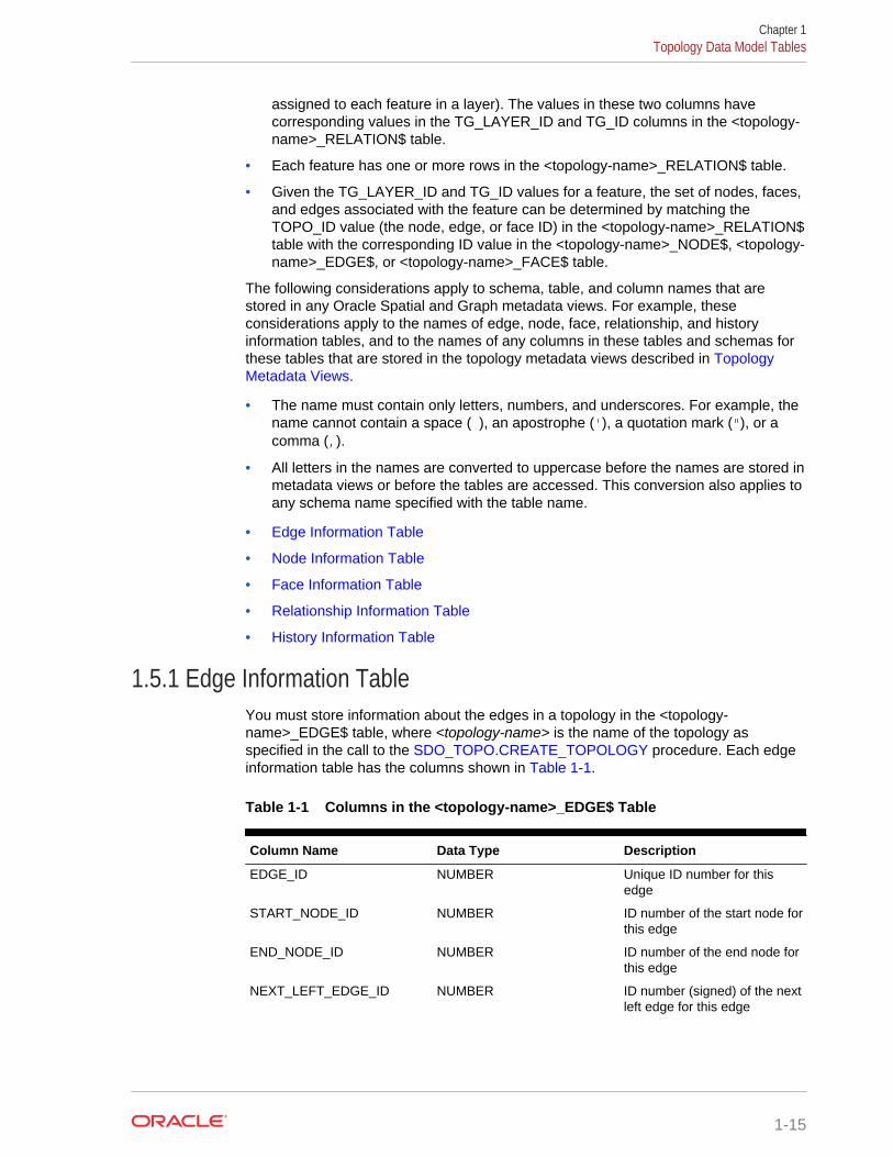
1.5.1 Edge Information TableYou must store information about the edges in a topology in the <topology-name>_EDGE$ table, where <topology-name> is the name of the topology asspecified in the call to the SDO_TOPO.CREATE_TOPOLOGY procedure. Each edgeinformation table has the columns shown in Table 1-1.
Table 1-1 Columns in the <topology-name>_EDGE$ Table
Column Name Data Type Description
EDGE_ID NUMBER Unique ID number for thisedge
START_NODE_ID NUMBER ID number of the start node forthis edge
END_NODE_ID NUMBER ID number of the end node forthis edge
NEXT_LEFT_EDGE_ID NUMBER ID number (signed) of the nextleft edge for this edge
Chapter 1Topology Data Model Tables
1-15

Table 1-1 (Cont.) Columns in the <topology-name>_EDGE$ Table
Column Name Data Type Description
PREV_LEFT_EDGE_ID NUMBER ID number (signed) of theprevious left edge for thisedge
NEXT_RIGHT_EDGE_ID NUMBER ID number (signed) of the nextright edge for this edge
PREV_RIGHT_EDGE_ID NUMBER ID number (signed) of theprevious right edge for thisedge
LEFT_FACE_ID NUMBER ID number of the left face forthis edge
RIGHT_FACE_ID NUMBER ID number of the right face forthis edge
GEOMETRY SDO_GEOMETRY Geometry object (line string)representing this edge, listingthe coordinates in the naturalorder for the positive directededge
The NEXT_LEFT_EDGE_ID and NEXT_RIGHT_EDGE_ID values refer to the nextdirected edges in the counterclockwise delineation of the perimeters of the left andright faces, respectively. The PREV_LEFT_EDGE_ID and PREV_RIGHT_EDGE_IDvalues refer to the previous directed edges in the counterclockwise delineation of theperimeters of the left and right faces, respectively. The LEFT_FACE_ID value refers tothe face to the left of the positive directed edge, and the RIGHT_FACE_ID value refersto the face to the left of the negative directed edge. For any numeric ID value, the signindicates which orientation of the target edge is being referred to.
Figure 1-6 shows nodes, edges, and faces that illustrate the relationships among thevarious ID columns in the edge information table. (In Figure 1-6, thick lines show theedges, and thin lines with arrowheads show the direction of each edge.)
Figure 1-6 Nodes, Edges, and Faces
N1
N3 N4
N2
E3
E2
E4
E5
E6
E8
F1
F2
E1 E7
Table 1-2 shows the ID column values in the edge information table for edges E4 andE8 in Figure 1-6. (For clarity, Table 1-2 shows ID column values with alphabetical
Chapter 1Topology Data Model Tables
1-16
characters, such as E4 and N1; however, the ID columns actually contain numericvalues only, specifically the numeric ID value associated with each named object.)
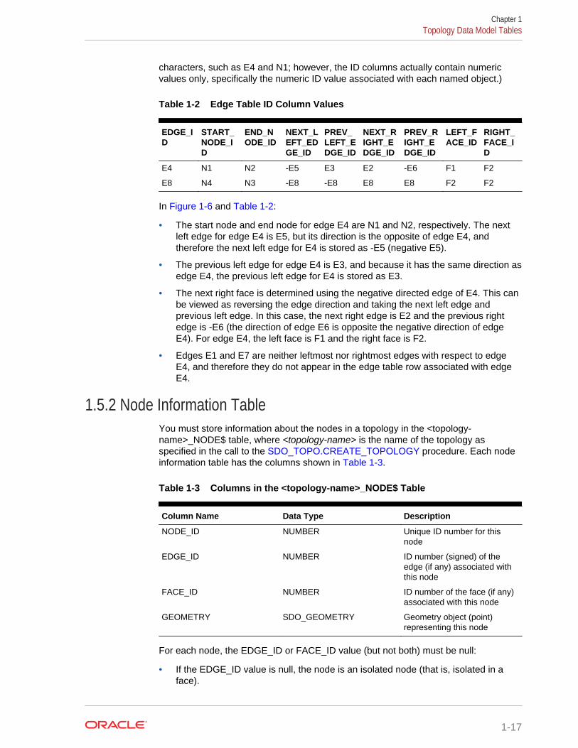
Table 1-2 Edge Table ID Column Values
EDGE_ID
START_NODE_ID
END_NODE_ID
NEXT_LEFT_EDGE_ID
PREV_LEFT_EDGE_ID
NEXT_RIGHT_EDGE_ID
PREV_RIGHT_EDGE_ID
LEFT_FACE_ID
RIGHT_FACE_ID
E4 N1 N2 -E5 E3 E2 -E6 F1 F2
E8 N4 N3 -E8 -E8 E8 E8 F2 F2
In Figure 1-6 and Table 1-2:
• The start node and end node for edge E4 are N1 and N2, respectively. The nextleft edge for edge E4 is E5, but its direction is the opposite of edge E4, andtherefore the next left edge for E4 is stored as -E5 (negative E5).
• The previous left edge for edge E4 is E3, and because it has the same direction asedge E4, the previous left edge for E4 is stored as E3.
• The next right face is determined using the negative directed edge of E4. This canbe viewed as reversing the edge direction and taking the next left edge andprevious left edge. In this case, the next right edge is E2 and the previous rightedge is -E6 (the direction of edge E6 is opposite the negative direction of edgeE4). For edge E4, the left face is F1 and the right face is F2.
• Edges E1 and E7 are neither leftmost nor rightmost edges with respect to edgeE4, and therefore they do not appear in the edge table row associated with edgeE4.
1.5.2 Node Information TableYou must store information about the nodes in a topology in the <topology-name>_NODE$ table, where <topology-name> is the name of the topology asspecified in the call to the SDO_TOPO.CREATE_TOPOLOGY procedure. Each nodeinformation table has the columns shown in Table 1-3.
Table 1-3 Columns in the <topology-name>_NODE$ Table
Column Name Data Type Description
NODE_ID NUMBER Unique ID number for thisnode
EDGE_ID NUMBER ID number (signed) of theedge (if any) associated withthis node
FACE_ID NUMBER ID number of the face (if any)associated with this node
GEOMETRY SDO_GEOMETRY Geometry object (point)representing this node
For each node, the EDGE_ID or FACE_ID value (but not both) must be null:
• If the EDGE_ID value is null, the node is an isolated node (that is, isolated in aface).
Chapter 1Topology Data Model Tables
1-17
• If the FACE_ID value is null, the node is not an isolated node, but rather the startnode or end node of an edge.
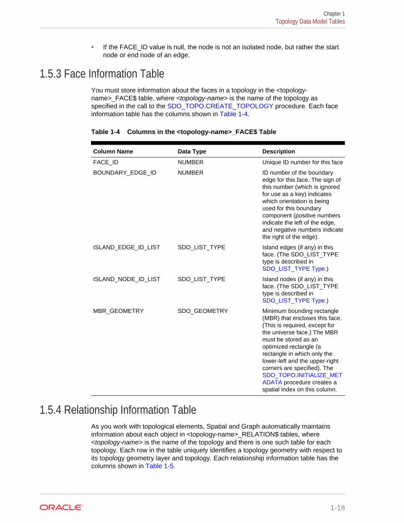
1.5.3 Face Information TableYou must store information about the faces in a topology in the <topology-name>_FACE$ table, where <topology-name> is the name of the topology asspecified in the call to the SDO_TOPO.CREATE_TOPOLOGY procedure. Each faceinformation table has the columns shown in Table 1-4.
Table 1-4 Columns in the <topology-name>_FACE$ Table
Column Name Data Type Description
FACE_ID NUMBER Unique ID number for this face
BOUNDARY_EDGE_ID NUMBER ID number of the boundaryedge for this face. The sign ofthis number (which is ignoredfor use as a key) indicateswhich orientation is beingused for this boundarycomponent (positive numbersindicate the left of the edge,and negative numbers indicatethe right of the edge).
ISLAND_EDGE_ID_LIST SDO_LIST_TYPE Island edges (if any) in thisface. (The SDO_LIST_TYPEtype is described in SDO_LIST_TYPE Type.)
ISLAND_NODE_ID_LIST SDO_LIST_TYPE Island nodes (if any) in thisface. (The SDO_LIST_TYPEtype is described in SDO_LIST_TYPE Type.)
MBR_GEOMETRY SDO_GEOMETRY Minimum bounding rectangle(MBR) that encloses this face.(This is required, except forthe universe face.) The MBRmust be stored as anoptimized rectangle (arectangle in which only thelower-left and the upper-rightcorners are specified). The SDO_TOPO.INITIALIZE_METADATA procedure creates aspatial index on this column.
1.5.4 Relationship Information TableAs you work with topological elements, Spatial and Graph automatically maintainsinformation about each object in <topology-name>_RELATION$ tables, where<topology-name> is the name of the topology and there is one such table for eachtopology. Each row in the table uniquely identifies a topology geometry with respect toits topology geometry layer and topology. Each relationship information table has thecolumns shown in Table 1-5.
Chapter 1Topology Data Model Tables
1-18
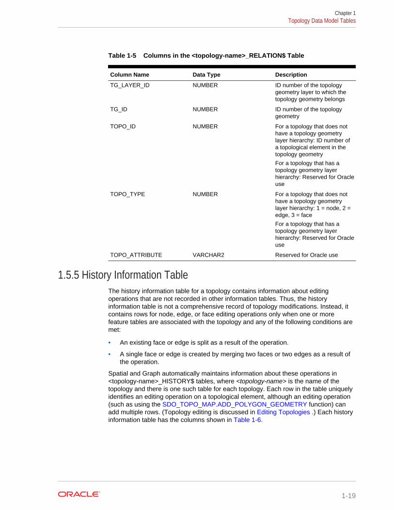
Table 1-5 Columns in the <topology-name>_RELATION$ Table
Column Name Data Type Description
TG_LAYER_ID NUMBER ID number of the topologygeometry layer to which thetopology geometry belongs
TG_ID NUMBER ID number of the topologygeometry
TOPO_ID NUMBER For a topology that does nothave a topology geometrylayer hierarchy: ID number ofa topological element in thetopology geometry
For a topology that has atopology geometry layerhierarchy: Reserved for Oracleuse
TOPO_TYPE NUMBER For a topology that does nothave a topology geometrylayer hierarchy: 1 = node, 2 =edge, 3 = face
For a topology that has atopology geometry layerhierarchy: Reserved for Oracleuse
TOPO_ATTRIBUTE VARCHAR2 Reserved for Oracle use
1.5.5 History Information TableThe history information table for a topology contains information about editingoperations that are not recorded in other information tables. Thus, the historyinformation table is not a comprehensive record of topology modifications. Instead, itcontains rows for node, edge, or face editing operations only when one or morefeature tables are associated with the topology and any of the following conditions aremet:
• An existing face or edge is split as a result of the operation.
• A single face or edge is created by merging two faces or two edges as a result ofthe operation.
Spatial and Graph automatically maintains information about these operations in<topology-name>_HISTORY$ tables, where <topology-name> is the name of thetopology and there is one such table for each topology. Each row in the table uniquelyidentifies an editing operation on a topological element, although an editing operation(such as using the SDO_TOPO_MAP.ADD_POLYGON_GEOMETRY function) canadd multiple rows. (Topology editing is discussed in Editing Topologies .) Each historyinformation table has the columns shown in Table 1-6.
Chapter 1Topology Data Model Tables
1-19
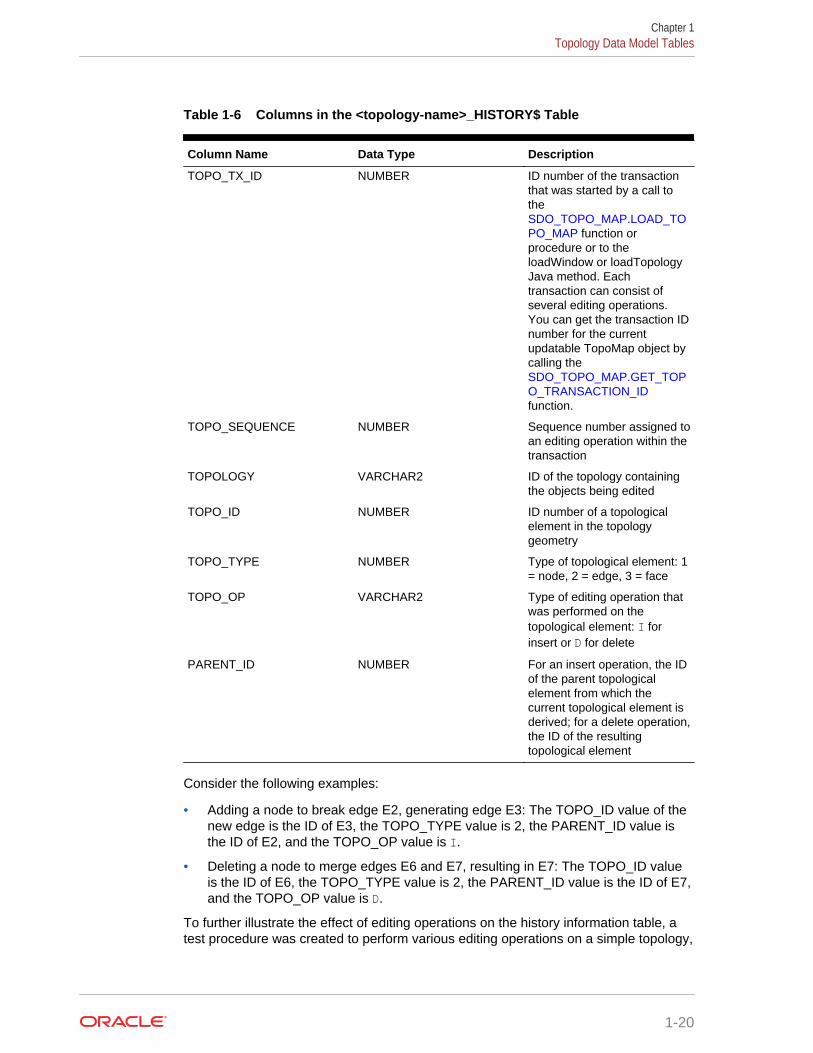
Table 1-6 Columns in the <topology-name>_HISTORY$ Table
Column Name Data Type Description
TOPO_TX_ID NUMBER ID number of the transactionthat was started by a call tothe SDO_TOPO_MAP.LOAD_TOPO_MAP function orprocedure or to theloadWindow or loadTopologyJava method. Eachtransaction can consist ofseveral editing operations.You can get the transaction IDnumber for the currentupdatable TopoMap object bycalling the SDO_TOPO_MAP.GET_TOPO_TRANSACTION_IDfunction.
TOPO_SEQUENCE NUMBER Sequence number assigned toan editing operation within thetransaction
TOPOLOGY VARCHAR2 ID of the topology containingthe objects being edited
TOPO_ID NUMBER ID number of a topologicalelement in the topologygeometry
TOPO_TYPE NUMBER Type of topological element: 1= node, 2 = edge, 3 = face
TOPO_OP VARCHAR2 Type of editing operation thatwas performed on thetopological element: I forinsert or D for delete
PARENT_ID NUMBER For an insert operation, the IDof the parent topologicalelement from which thecurrent topological element isderived; for a delete operation,the ID of the resultingtopological element
Consider the following examples:
• Adding a node to break edge E2, generating edge E3: The TOPO_ID value of thenew edge is the ID of E3, the TOPO_TYPE value is 2, the PARENT_ID value isthe ID of E2, and the TOPO_OP value is I.
• Deleting a node to merge edges E6 and E7, resulting in E7: The TOPO_ID valueis the ID of E6, the TOPO_TYPE value is 2, the PARENT_ID value is the ID of E7,and the TOPO_OP value is D.
To further illustrate the effect of editing operations on the history information table, atest procedure was created to perform various editing operations on a simple topology,
Chapter 1Topology Data Model Tables
1-20
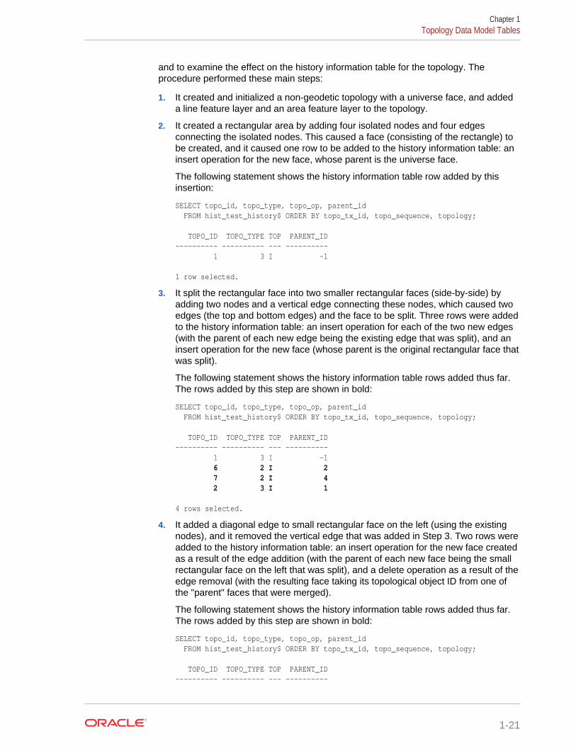
and to examine the effect on the history information table for the topology. Theprocedure performed these main steps:
1. It created and initialized a non-geodetic topology with a universe face, and addeda line feature layer and an area feature layer to the topology.
2. It created a rectangular area by adding four isolated nodes and four edgesconnecting the isolated nodes. This caused a face (consisting of the rectangle) tobe created, and it caused one row to be added to the history information table: aninsert operation for the new face, whose parent is the universe face.
The following statement shows the history information table row added by thisinsertion:
SELECT topo_id, topo_type, topo_op, parent_id FROM hist_test_history$ ORDER BY topo_tx_id, topo_sequence, topology; TOPO_ID TOPO_TYPE TOP PARENT_ID---------- ---------- --- ---------- 1 3 I -1 1 row selected.
3. It split the rectangular face into two smaller rectangular faces (side-by-side) byadding two nodes and a vertical edge connecting these nodes, which caused twoedges (the top and bottom edges) and the face to be split. Three rows were addedto the history information table: an insert operation for each of the two new edges(with the parent of each new edge being the existing edge that was split), and aninsert operation for the new face (whose parent is the original rectangular face thatwas split).
The following statement shows the history information table rows added thus far.The rows added by this step are shown in bold:
SELECT topo_id, topo_type, topo_op, parent_id FROM hist_test_history$ ORDER BY topo_tx_id, topo_sequence, topology; TOPO_ID TOPO_TYPE TOP PARENT_ID---------- ---------- --- ---------- 1 3 I -1 6 2 I 2 7 2 I 4 2 3 I 1 4 rows selected.
4. It added a diagonal edge to small rectangular face on the left (using the existingnodes), and it removed the vertical edge that was added in Step 3. Two rows wereadded to the history information table: an insert operation for the new face createdas a result of the edge addition (with the parent of each new face being the smallrectangular face on the left that was split), and a delete operation as a result of theedge removal (with the resulting face taking its topological object ID from one ofthe "parent" faces that were merged).
The following statement shows the history information table rows added thus far.The rows added by this step are shown in bold:
SELECT topo_id, topo_type, topo_op, parent_id FROM hist_test_history$ ORDER BY topo_tx_id, topo_sequence, topology; TOPO_ID TOPO_TYPE TOP PARENT_ID---------- ---------- --- ----------
Chapter 1Topology Data Model Tables
1-21
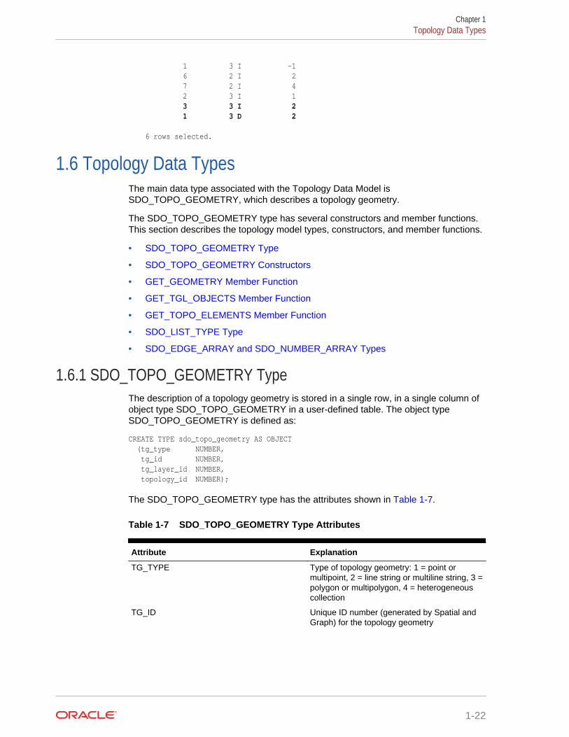
1 3 I -1 6 2 I 2 7 2 I 4 2 3 I 1 3 3 I 2 1 3 D 2 6 rows selected.
1.6 Topology Data TypesThe main data type associated with the Topology Data Model isSDO_TOPO_GEOMETRY, which describes a topology geometry.
The SDO_TOPO_GEOMETRY type has several constructors and member functions.This section describes the topology model types, constructors, and member functions.
• SDO_TOPO_GEOMETRY Type
• SDO_TOPO_GEOMETRY Constructors
• GET_GEOMETRY Member Function
• GET_TGL_OBJECTS Member Function
• GET_TOPO_ELEMENTS Member Function
• SDO_LIST_TYPE Type
• SDO_EDGE_ARRAY and SDO_NUMBER_ARRAY Types
1.6.1 SDO_TOPO_GEOMETRY TypeThe description of a topology geometry is stored in a single row, in a single column ofobject type SDO_TOPO_GEOMETRY in a user-defined table. The object typeSDO_TOPO_GEOMETRY is defined as:
CREATE TYPE sdo_topo_geometry AS OBJECT (tg_type NUMBER, tg_id NUMBER, tg_layer_id NUMBER, topology_id NUMBER);
The SDO_TOPO_GEOMETRY type has the attributes shown in Table 1-7.
Table 1-7 SDO_TOPO_GEOMETRY Type Attributes
Attribute Explanation
TG_TYPE Type of topology geometry: 1 = point ormultipoint, 2 = line string or multiline string, 3 =polygon or multipolygon, 4 = heterogeneouscollection
TG_ID Unique ID number (generated by Spatial andGraph) for the topology geometry
Chapter 1Topology Data Types
1-22
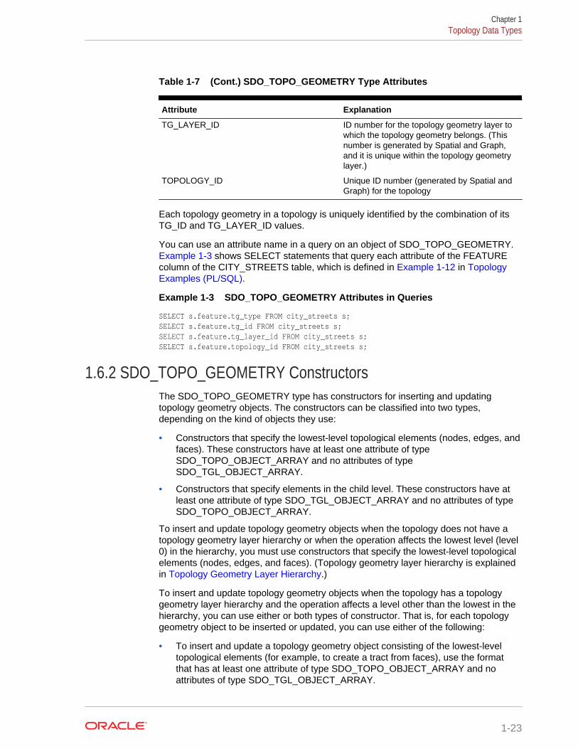
Table 1-7 (Cont.) SDO_TOPO_GEOMETRY Type Attributes
Attribute Explanation
TG_LAYER_ID ID number for the topology geometry layer towhich the topology geometry belongs. (Thisnumber is generated by Spatial and Graph,and it is unique within the topology geometrylayer.)
TOPOLOGY_ID Unique ID number (generated by Spatial andGraph) for the topology
Each topology geometry in a topology is uniquely identified by the combination of itsTG_ID and TG_LAYER_ID values.
You can use an attribute name in a query on an object of SDO_TOPO_GEOMETRY. Example 1-3 shows SELECT statements that query each attribute of the FEATUREcolumn of the CITY_STREETS table, which is defined in Example 1-12 in TopologyExamples (PL/SQL).
Example 1-3 SDO_TOPO_GEOMETRY Attributes in Queries
SELECT s.feature.tg_type FROM city_streets s;SELECT s.feature.tg_id FROM city_streets s;SELECT s.feature.tg_layer_id FROM city_streets s;SELECT s.feature.topology_id FROM city_streets s;
1.6.2 SDO_TOPO_GEOMETRY ConstructorsThe SDO_TOPO_GEOMETRY type has constructors for inserting and updatingtopology geometry objects. The constructors can be classified into two types,depending on the kind of objects they use:
• Constructors that specify the lowest-level topological elements (nodes, edges, andfaces). These constructors have at least one attribute of typeSDO_TOPO_OBJECT_ARRAY and no attributes of typeSDO_TGL_OBJECT_ARRAY.
• Constructors that specify elements in the child level. These constructors have atleast one attribute of type SDO_TGL_OBJECT_ARRAY and no attributes of typeSDO_TOPO_OBJECT_ARRAY.
To insert and update topology geometry objects when the topology does not have atopology geometry layer hierarchy or when the operation affects the lowest level (level0) in the hierarchy, you must use constructors that specify the lowest-level topologicalelements (nodes, edges, and faces). (Topology geometry layer hierarchy is explainedin Topology Geometry Layer Hierarchy.)
To insert and update topology geometry objects when the topology has a topologygeometry layer hierarchy and the operation affects a level other than the lowest in thehierarchy, you can use either or both types of constructor. That is, for each topologygeometry object to be inserted or updated, you can use either of the following:
• To insert and update a topology geometry object consisting of the lowest-leveltopological elements (for example, to create a tract from faces), use the formatthat has at least one attribute of type SDO_TOPO_OBJECT_ARRAY and noattributes of type SDO_TGL_OBJECT_ARRAY.
Chapter 1Topology Data Types
1-23
• To insert and update a topology geometry object consisting of features at the nextlower level (for example, create a tract from block groups), use the format that hasat least one attribute of type SDO_TGL_OBJECT_ARRAY and no attributes oftype SDO_TOPO_OBJECT_ARRAY.
This section describes the available SDO_TOPO_GEOMETRY constructors.
Note:
An additional SDO_TOPO_GEOMETRY constructor with the same attributesas the type definition (tg_type, tg_id, tg_layer_id, topology_id) is forOracle internal use only.
• Constructors for Insert Operations: Specifying Topological Elements
• Constructors for Insert Operations: Specifying Lower-Level Features
• Constructors for Update Operations: Specifying Topological Elements
• Constructors for Update Operations: Specifying Lower-Level Features
1.6.2.1 Constructors for Insert Operations: Specifying Topological ElementsThe SDO_TOPO_GEOMETRY type has the following constructors for insertoperations in which you specify topological elements (faces, nodes, or edges). Youmust use one of these formats to create new topology geometry objects when thetopology does not have a topology geometry layer hierarchy or when the operationaffects the lowest level (level 0) in the hierarchy, and you can use one of these formatsto create new topology geometry objects when the operation affects a level higherthan level 0 in the hierarchy:
SDO_TOPO_GEOMETRY (topology VARCHAR2, tg_type NUMBER, tg_layer_id NUMBER, topo_ids SDO_TOPO_OBJECT_ARRAY)
SDO_TOPO_GEOMETRY (topology VARCHAR2, table_name VARCHAR2, column_name VARCHAR2, tg_type NUMBER, topo_ids SDO_TOPO_OBJECT_ARRAY)
The SDO_TOPO_OBJECT_ARRAY type is defined as a VARRAY ofSDO_TOPO_OBJECT objects.
The SDO_TOPO_OBJECT type has the following two attributes:
(topo_id NUMBER, topo_type NUMBER)
The TG_TYPE and TOPO_IDS attribute values must be within the range of valuesfrom the <topology-name>_RELATION$ table (described in Relationship InformationTable) for the specified topology.
Example 1-4 shows two SDO_TOPO_GEOMETRY constructors, one in each format.Each constructor inserts a topology geometry into the LAND_PARCELS table, which isdefined in Example 1-12 in Topology Examples (PL/SQL).
Chapter 1Topology Data Types
1-24
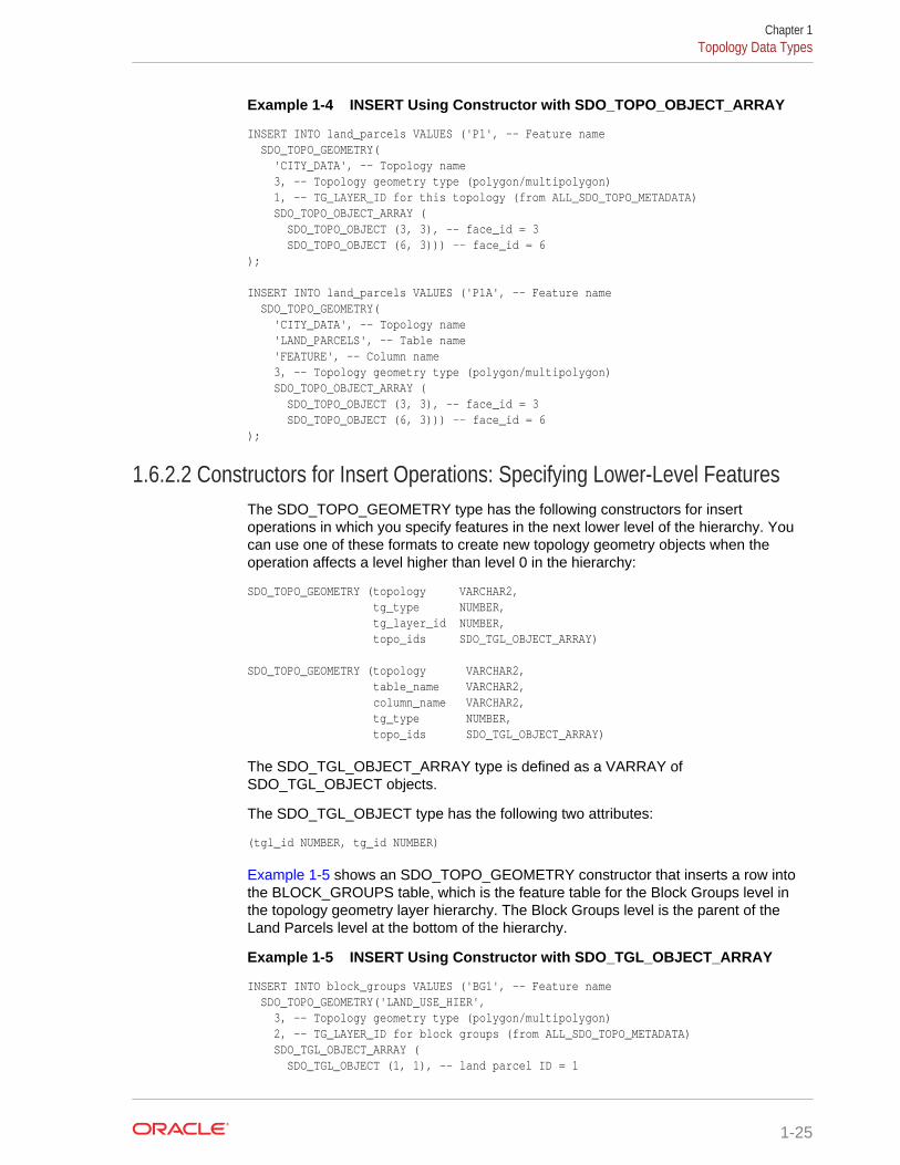
Example 1-4 INSERT Using Constructor with SDO_TOPO_OBJECT_ARRAY
INSERT INTO land_parcels VALUES ('P1', -- Feature name SDO_TOPO_GEOMETRY( 'CITY_DATA', -- Topology name 3, -- Topology geometry type (polygon/multipolygon) 1, -- TG_LAYER_ID for this topology (from ALL_SDO_TOPO_METADATA) SDO_TOPO_OBJECT_ARRAY ( SDO_TOPO_OBJECT (3, 3), -- face_id = 3 SDO_TOPO_OBJECT (6, 3))) -- face_id = 6);
INSERT INTO land_parcels VALUES ('P1A', -- Feature name SDO_TOPO_GEOMETRY( 'CITY_DATA', -- Topology name 'LAND_PARCELS', -- Table name 'FEATURE', -- Column name 3, -- Topology geometry type (polygon/multipolygon) SDO_TOPO_OBJECT_ARRAY ( SDO_TOPO_OBJECT (3, 3), -- face_id = 3 SDO_TOPO_OBJECT (6, 3))) -- face_id = 6);
1.6.2.2 Constructors for Insert Operations: Specifying Lower-Level FeaturesThe SDO_TOPO_GEOMETRY type has the following constructors for insertoperations in which you specify features in the next lower level of the hierarchy. Youcan use one of these formats to create new topology geometry objects when theoperation affects a level higher than level 0 in the hierarchy:
SDO_TOPO_GEOMETRY (topology VARCHAR2, tg_type NUMBER, tg_layer_id NUMBER, topo_ids SDO_TGL_OBJECT_ARRAY)
SDO_TOPO_GEOMETRY (topology VARCHAR2, table_name VARCHAR2, column_name VARCHAR2, tg_type NUMBER, topo_ids SDO_TGL_OBJECT_ARRAY)
The SDO_TGL_OBJECT_ARRAY type is defined as a VARRAY ofSDO_TGL_OBJECT objects.
The SDO_TGL_OBJECT type has the following two attributes:
(tgl_id NUMBER, tg_id NUMBER)
Example 1-5 shows an SDO_TOPO_GEOMETRY constructor that inserts a row intothe BLOCK_GROUPS table, which is the feature table for the Block Groups level inthe topology geometry layer hierarchy. The Block Groups level is the parent of theLand Parcels level at the bottom of the hierarchy.
Example 1-5 INSERT Using Constructor with SDO_TGL_OBJECT_ARRAY
INSERT INTO block_groups VALUES ('BG1', -- Feature name SDO_TOPO_GEOMETRY('LAND_USE_HIER', 3, -- Topology geometry type (polygon/multipolygon) 2, -- TG_LAYER_ID for block groups (from ALL_SDO_TOPO_METADATA) SDO_TGL_OBJECT_ARRAY ( SDO_TGL_OBJECT (1, 1), -- land parcel ID = 1
Chapter 1Topology Data Types
1-25
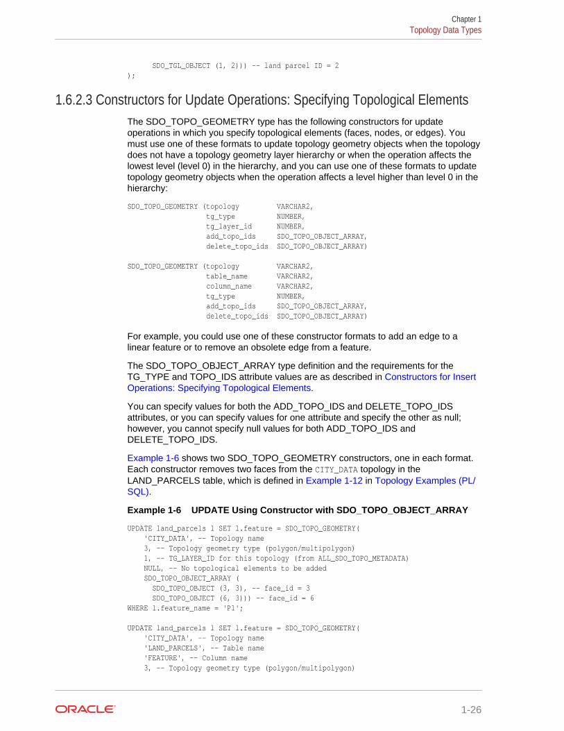
SDO_TGL_OBJECT (1, 2))) -- land parcel ID = 2);
1.6.2.3 Constructors for Update Operations: Specifying Topological ElementsThe SDO_TOPO_GEOMETRY type has the following constructors for updateoperations in which you specify topological elements (faces, nodes, or edges). Youmust use one of these formats to update topology geometry objects when the topologydoes not have a topology geometry layer hierarchy or when the operation affects thelowest level (level 0) in the hierarchy, and you can use one of these formats to updatetopology geometry objects when the operation affects a level higher than level 0 in thehierarchy:
SDO_TOPO_GEOMETRY (topology VARCHAR2, tg_type NUMBER, tg_layer_id NUMBER, add_topo_ids SDO_TOPO_OBJECT_ARRAY, delete_topo_ids SDO_TOPO_OBJECT_ARRAY)
SDO_TOPO_GEOMETRY (topology VARCHAR2, table_name VARCHAR2, column_name VARCHAR2, tg_type NUMBER, add_topo_ids SDO_TOPO_OBJECT_ARRAY, delete_topo_ids SDO_TOPO_OBJECT_ARRAY)
For example, you could use one of these constructor formats to add an edge to alinear feature or to remove an obsolete edge from a feature.
The SDO_TOPO_OBJECT_ARRAY type definition and the requirements for theTG_TYPE and TOPO_IDS attribute values are as described in Constructors for InsertOperations: Specifying Topological Elements.
You can specify values for both the ADD_TOPO_IDS and DELETE_TOPO_IDSattributes, or you can specify values for one attribute and specify the other as null;however, you cannot specify null values for both ADD_TOPO_IDS andDELETE_TOPO_IDS.
Example 1-6 shows two SDO_TOPO_GEOMETRY constructors, one in each format.Each constructor removes two faces from the CITY_DATA topology in theLAND_PARCELS table, which is defined in Example 1-12 in Topology Examples (PL/SQL).
Example 1-6 UPDATE Using Constructor with SDO_TOPO_OBJECT_ARRAY
UPDATE land_parcels l SET l.feature = SDO_TOPO_GEOMETRY( 'CITY_DATA', -- Topology name 3, -- Topology geometry type (polygon/multipolygon) 1, -- TG_LAYER_ID for this topology (from ALL_SDO_TOPO_METADATA) NULL, -- No topological elements to be added SDO_TOPO_OBJECT_ARRAY ( SDO_TOPO_OBJECT (3, 3), -- face_id = 3 SDO_TOPO_OBJECT (6, 3))) -- face_id = 6WHERE l.feature_name = 'P1'; UPDATE land_parcels l SET l.feature = SDO_TOPO_GEOMETRY( 'CITY_DATA', -- Topology name 'LAND_PARCELS', -- Table name 'FEATURE', -- Column name 3, -- Topology geometry type (polygon/multipolygon)
Chapter 1Topology Data Types
1-26
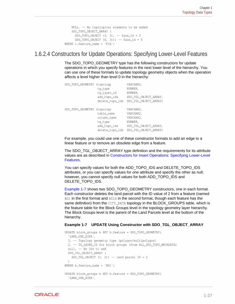
NULL, -- No topological elements to be added SDO_TOPO_OBJECT_ARRAY ( SDO_TOPO_OBJECT (3, 3), -- face_id = 3 SDO_TOPO_OBJECT (6, 3))) -- face_id = 6WHERE l.feature_name = 'P1A';
1.6.2.4 Constructors for Update Operations: Specifying Lower-Level FeaturesThe SDO_TOPO_GEOMETRY type has the following constructors for updateoperations in which you specify features in the next lower level of the hierarchy. Youcan use one of these formats to update topology geometry objects when the operationaffects a level higher than level 0 in the hierarchy:
SDO_TOPO_GEOMETRY (topology VARCHAR2, tg_type NUMBER, tg_layer_id NUMBER, add_topo_ids SDO_TGL_OBJECT_ARRAY, delete_topo_ids SDO_TGL_OBJECT_ARRAY)
SDO_TOPO_GEOMETRY (topology VARCHAR2, table_name VARCHAR2, column_name VARCHAR2, tg_type NUMBER, add_topo_ids SDO_TGL_OBJECT_ARRAY, delete_topo_ids SDO_TGL_OBJECT_ARRAY)
For example, you could use one of these constructor formats to add an edge to alinear feature or to remove an obsolete edge from a feature.
The SDO_TGL_OBJECT_ARRAY type definition and the requirements for its attributevalues are as described in Constructors for Insert Operations: Specifying Lower-LevelFeatures.
You can specify values for both the ADD_TOPO_IDS and DELETE_TOPO_IDSattributes, or you can specify values for one attribute and specify the other as null;however, you cannot specify null values for both ADD_TOPO_IDS andDELETE_TOPO_IDS.
Example 1-7 shows two SDO_TOPO_GEOMETRY constructors, one in each format.Each constructor deletes the land parcel with the ID value of 2 from a feature (namedBG1 in the first format and BG1A in the second format, though each feature has thesame definition) from the CITY_DATA topology in the BLOCK_GROUPS table, which isthe feature table for the Block Groups level in the topology geometry layer hierarchy.The Block Groups level is the parent of the Land Parcels level at the bottom of thehierarchy.
Example 1-7 UPDATE Using Constructor with SDO_TGL_OBJECT_ARRAY
UPDATE block_groups b SET b.feature = SDO_TOPO_GEOMETRY( 'LAND_USE_HIER', 3, -- Topology geometry type (polygon/multipolygon) 2, -- TG_LAYER_ID for block groups (from ALL_SDO_TOPO_METADATA) null, -- No IDs to add SDO_TGL_OBJECT_ARRAY ( SDO_TGL_OBJECT (1, 2)) -- land parcel ID = 2 )WHERE b.feature_name = 'BG1'; UPDATE block_groups b SET b.feature = SDO_TOPO_GEOMETRY( 'LAND_USE_HIER',
Chapter 1Topology Data Types
1-27
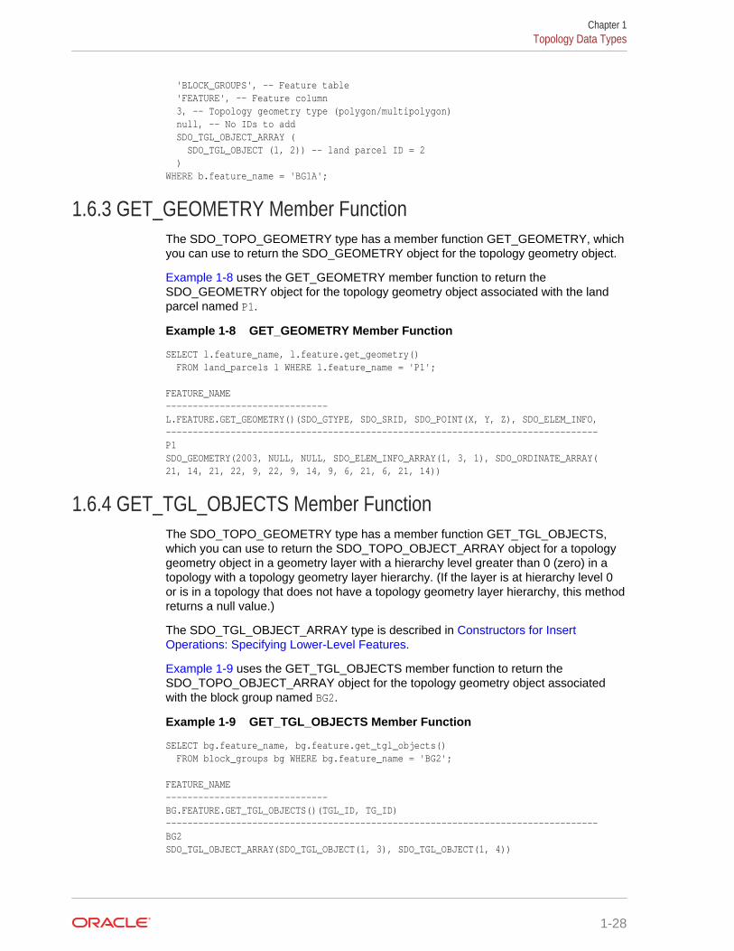
'BLOCK_GROUPS', -- Feature table 'FEATURE', -- Feature column 3, -- Topology geometry type (polygon/multipolygon) null, -- No IDs to add SDO_TGL_OBJECT_ARRAY ( SDO_TGL_OBJECT (1, 2)) -- land parcel ID = 2 )WHERE b.feature_name = 'BG1A';
1.6.3 GET_GEOMETRY Member FunctionThe SDO_TOPO_GEOMETRY type has a member function GET_GEOMETRY, whichyou can use to return the SDO_GEOMETRY object for the topology geometry object.
Example 1-8 uses the GET_GEOMETRY member function to return theSDO_GEOMETRY object for the topology geometry object associated with the landparcel named P1.
Example 1-8 GET_GEOMETRY Member Function
SELECT l.feature_name, l.feature.get_geometry() FROM land_parcels l WHERE l.feature_name = 'P1'; FEATURE_NAME ------------------------------ L.FEATURE.GET_GEOMETRY()(SDO_GTYPE, SDO_SRID, SDO_POINT(X, Y, Z), SDO_ELEM_INFO,--------------------------------------------------------------------------------P1 SDO_GEOMETRY(2003, NULL, NULL, SDO_ELEM_INFO_ARRAY(1, 3, 1), SDO_ORDINATE_ARRAY(21, 14, 21, 22, 9, 22, 9, 14, 9, 6, 21, 6, 21, 14))
1.6.4 GET_TGL_OBJECTS Member FunctionThe SDO_TOPO_GEOMETRY type has a member function GET_TGL_OBJECTS,which you can use to return the SDO_TOPO_OBJECT_ARRAY object for a topologygeometry object in a geometry layer with a hierarchy level greater than 0 (zero) in atopology with a topology geometry layer hierarchy. (If the layer is at hierarchy level 0or is in a topology that does not have a topology geometry layer hierarchy, this methodreturns a null value.)
The SDO_TGL_OBJECT_ARRAY type is described in Constructors for InsertOperations: Specifying Lower-Level Features.
Example 1-9 uses the GET_TGL_OBJECTS member function to return theSDO_TOPO_OBJECT_ARRAY object for the topology geometry object associatedwith the block group named BG2.
Example 1-9 GET_TGL_OBJECTS Member Function
SELECT bg.feature_name, bg.feature.get_tgl_objects() FROM block_groups bg WHERE bg.feature_name = 'BG2'; FEATURE_NAME ------------------------------ BG.FEATURE.GET_TGL_OBJECTS()(TGL_ID, TG_ID) --------------------------------------------------------------------------------BG2 SDO_TGL_OBJECT_ARRAY(SDO_TGL_OBJECT(1, 3), SDO_TGL_OBJECT(1, 4))
Chapter 1Topology Data Types
1-28
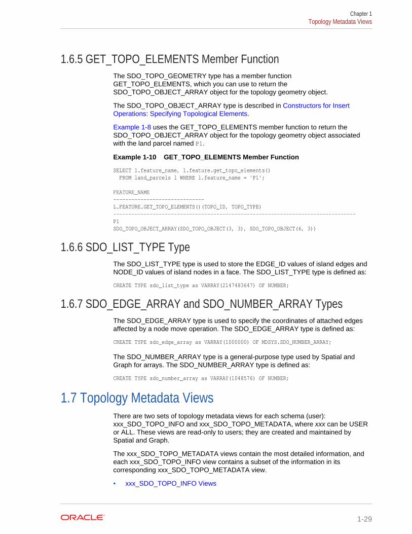
1.6.5 GET_TOPO_ELEMENTS Member FunctionThe SDO_TOPO_GEOMETRY type has a member functionGET_TOPO_ELEMENTS, which you can use to return theSDO_TOPO_OBJECT_ARRAY object for the topology geometry object.
The SDO_TOPO_OBJECT_ARRAY type is described in Constructors for InsertOperations: Specifying Topological Elements.
Example 1-8 uses the GET_TOPO_ELEMENTS member function to return theSDO_TOPO_OBJECT_ARRAY object for the topology geometry object associatedwith the land parcel named P1.
Example 1-10 GET_TOPO_ELEMENTS Member Function
SELECT l.feature_name, l.feature.get_topo_elements() FROM land_parcels l WHERE l.feature_name = 'P1'; FEATURE_NAME ------------------------------ L.FEATURE.GET_TOPO_ELEMENTS()(TOPO_ID, TOPO_TYPE) --------------------------------------------------------------------------------P1 SDO_TOPO_OBJECT_ARRAY(SDO_TOPO_OBJECT(3, 3), SDO_TOPO_OBJECT(6, 3))
1.6.6 SDO_LIST_TYPE TypeThe SDO_LIST_TYPE type is used to store the EDGE_ID values of island edges andNODE_ID values of island nodes in a face. The SDO_LIST_TYPE type is defined as:
CREATE TYPE sdo_list_type as VARRAY(2147483647) OF NUMBER;
1.6.7 SDO_EDGE_ARRAY and SDO_NUMBER_ARRAY TypesThe SDO_EDGE_ARRAY type is used to specify the coordinates of attached edgesaffected by a node move operation. The SDO_EDGE_ARRAY type is defined as:
CREATE TYPE sdo_edge_array as VARRAY(1000000) OF MDSYS.SDO_NUMBER_ARRAY;
The SDO_NUMBER_ARRAY type is a general-purpose type used by Spatial andGraph for arrays. The SDO_NUMBER_ARRAY type is defined as:
CREATE TYPE sdo_number_array as VARRAY(1048576) OF NUMBER;
1.7 Topology Metadata ViewsThere are two sets of topology metadata views for each schema (user):xxx_SDO_TOPO_INFO and xxx_SDO_TOPO_METADATA, where xxx can be USERor ALL. These views are read-only to users; they are created and maintained bySpatial and Graph.
The xxx_SDO_TOPO_METADATA views contain the most detailed information, andeach xxx_SDO_TOPO_INFO view contains a subset of the information in itscorresponding xxx_SDO_TOPO_METADATA view.
• xxx_SDO_TOPO_INFO Views
Chapter 1Topology Metadata Views
1-29
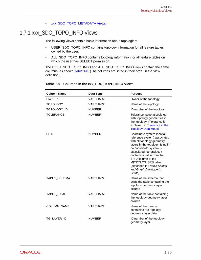
• xxx_SDO_TOPO_METADATA Views
1.7.1 xxx_SDO_TOPO_INFO ViewsThe following views contain basic information about topologies:
• USER_SDO_TOPO_INFO contains topology information for all feature tablesowned by the user.
• ALL_SDO_TOPO_INFO contains topology information for all feature tables onwhich the user has SELECT permission.
The USER_SDO_TOPO_INFO and ALL_SDO_TOPO_INFO views contain the samecolumns, as shown Table 1-8. (The columns are listed in their order in the viewdefinition.)
Table 1-8 Columns in the xxx_SDO_TOPO_INFO Views
Column Name Data Type Purpose
OWNER VARCHAR2 Owner of the topology
TOPOLOGY VARCHAR2 Name of the topology
TOPOLOGY_ID NUMBER ID number of the topology
TOLERANCE NUMBER Tolerance value associatedwith topology geometries inthe topology. (Tolerance isexplained in Tolerance in theTopology Data Model.)
SRID NUMBER Coordinate system (spatialreference system) associatedwith all topology geometrylayers in the topology. Is null ifno coordinate system isassociated; otherwise, itcontains a value from theSRID column of theMDSYS.CS_SRS table(described in Oracle Spatialand Graph Developer'sGuide).
TABLE_SCHEMA VARCHAR2 Name of the schema thatowns the table containing thetopology geometry layercolumn
TABLE_NAME VARCHAR2 Name of the table containingthe topology geometry layercolumn
COLUMN_NAME VARCHAR2 Name of the columncontaining the topologygeometry layer data
TG_LAYER_ID NUMBER ID number of the topologygeometry layer
Chapter 1Topology Metadata Views
1-30
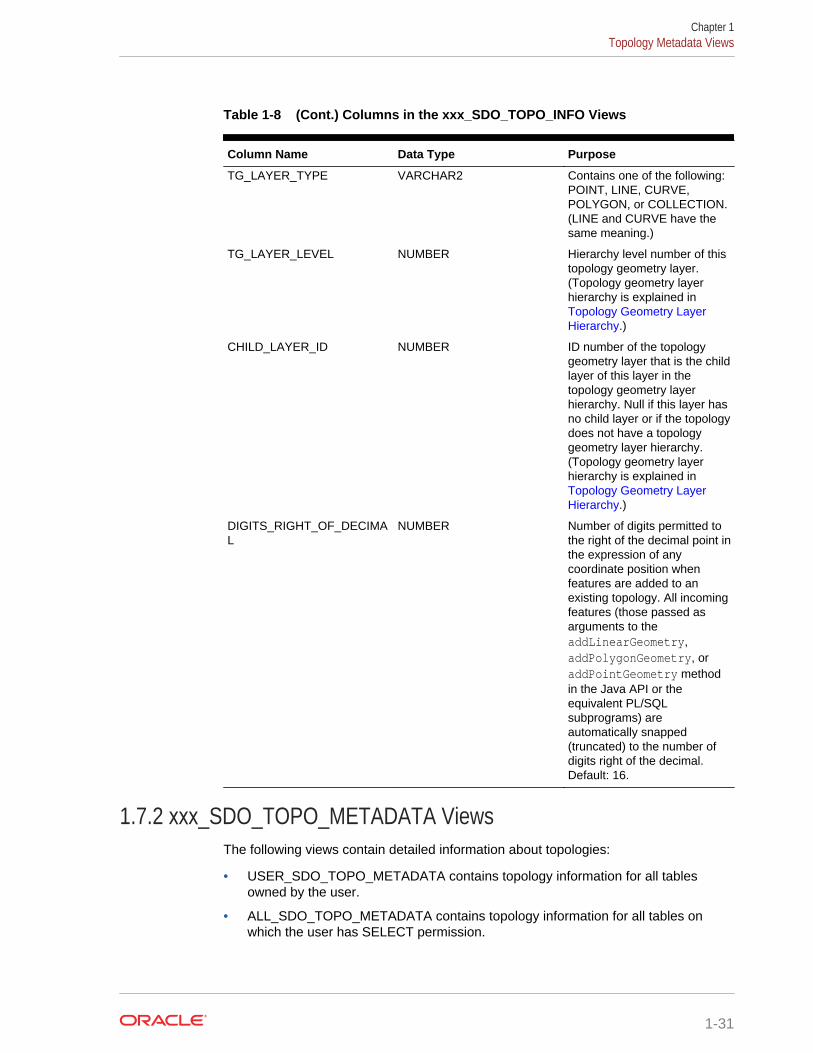
Table 1-8 (Cont.) Columns in the xxx_SDO_TOPO_INFO Views
Column Name Data Type Purpose
TG_LAYER_TYPE VARCHAR2 Contains one of the following:POINT, LINE, CURVE,POLYGON, or COLLECTION.(LINE and CURVE have thesame meaning.)
TG_LAYER_LEVEL NUMBER Hierarchy level number of thistopology geometry layer.(Topology geometry layerhierarchy is explained in Topology Geometry LayerHierarchy.)
CHILD_LAYER_ID NUMBER ID number of the topologygeometry layer that is the childlayer of this layer in thetopology geometry layerhierarchy. Null if this layer hasno child layer or if the topologydoes not have a topologygeometry layer hierarchy.(Topology geometry layerhierarchy is explained in Topology Geometry LayerHierarchy.)
DIGITS_RIGHT_OF_DECIMAL
NUMBER Number of digits permitted tothe right of the decimal point inthe expression of anycoordinate position whenfeatures are added to anexisting topology. All incomingfeatures (those passed asarguments to theaddLinearGeometry,addPolygonGeometry, oraddPointGeometry methodin the Java API or theequivalent PL/SQLsubprograms) areautomatically snapped(truncated) to the number ofdigits right of the decimal.Default: 16.
1.7.2 xxx_SDO_TOPO_METADATA ViewsThe following views contain detailed information about topologies:
• USER_SDO_TOPO_METADATA contains topology information for all tablesowned by the user.
• ALL_SDO_TOPO_METADATA contains topology information for all tables onwhich the user has SELECT permission.
Chapter 1Topology Metadata Views
1-31
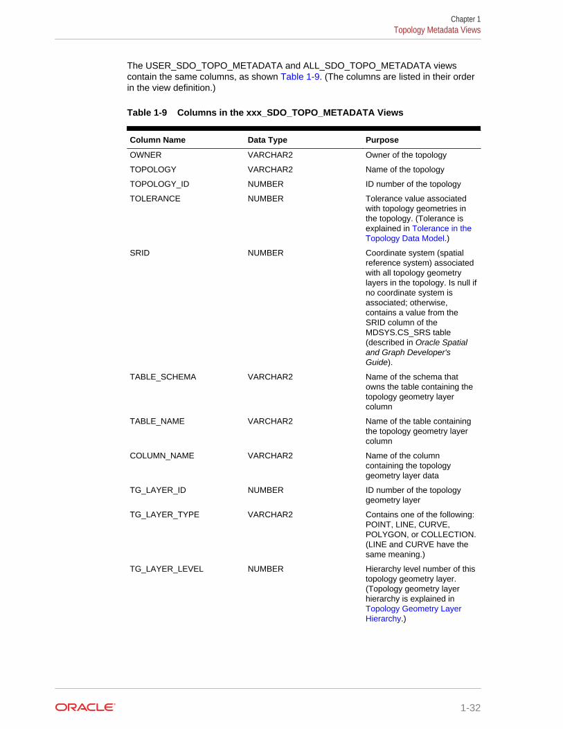
The USER_SDO_TOPO_METADATA and ALL_SDO_TOPO_METADATA viewscontain the same columns, as shown Table 1-9. (The columns are listed in their orderin the view definition.)
Table 1-9 Columns in the xxx_SDO_TOPO_METADATA Views
Column Name Data Type Purpose
OWNER VARCHAR2 Owner of the topology
TOPOLOGY VARCHAR2 Name of the topology
TOPOLOGY_ID NUMBER ID number of the topology
TOLERANCE NUMBER Tolerance value associatedwith topology geometries inthe topology. (Tolerance isexplained in Tolerance in theTopology Data Model.)
SRID NUMBER Coordinate system (spatialreference system) associatedwith all topology geometrylayers in the topology. Is null ifno coordinate system isassociated; otherwise,contains a value from theSRID column of theMDSYS.CS_SRS table(described in Oracle Spatialand Graph Developer'sGuide).
TABLE_SCHEMA VARCHAR2 Name of the schema thatowns the table containing thetopology geometry layercolumn
TABLE_NAME VARCHAR2 Name of the table containingthe topology geometry layercolumn
COLUMN_NAME VARCHAR2 Name of the columncontaining the topologygeometry layer data
TG_LAYER_ID NUMBER ID number of the topologygeometry layer
TG_LAYER_TYPE VARCHAR2 Contains one of the following:POINT, LINE, CURVE,POLYGON, or COLLECTION.(LINE and CURVE have thesame meaning.)
TG_LAYER_LEVEL NUMBER Hierarchy level number of thistopology geometry layer.(Topology geometry layerhierarchy is explained in Topology Geometry LayerHierarchy.)
Chapter 1Topology Metadata Views
1-32
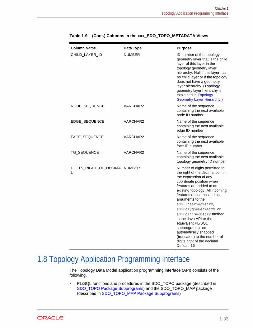
Table 1-9 (Cont.) Columns in the xxx_SDO_TOPO_METADATA Views
Column Name Data Type Purpose
CHILD_LAYER_ID NUMBER ID number of the topologygeometry layer that is the childlayer of this layer in thetopology geometry layerhierarchy. Null if this layer hasno child layer or if the topologydoes not have a geometrylayer hierarchy. (Topologygeometry layer hierarchy isexplained in TopologyGeometry Layer Hierarchy.)
NODE_SEQUENCE VARCHAR2 Name of the sequencecontaining the next availablenode ID number
EDGE_SEQUENCE VARCHAR2 Name of the sequencecontaining the next availableedge ID number
FACE_SEQUENCE VARCHAR2 Name of the sequencecontaining the next availableface ID number
TG_SEQUENCE VARCHAR2 Name of the sequencecontaining the next availabletopology geometry ID number
DIGITS_RIGHT_OF_DECIMAL
NUMBER Number of digits permitted tothe right of the decimal point inthe expression of anycoordinate position whenfeatures are added to anexisting topology. All incomingfeatures (those passed asarguments to theaddLinearGeometry,addPolygonGeometry, oraddPointGeometry methodin the Java API or theequivalent PL/SQLsubprograms) areautomatically snapped(truncated) to the number ofdigits right of the decimal.Default: 16
1.8 Topology Application Programming InterfaceThe Topology Data Model application programming interface (API) consists of thefollowing.
• PL/SQL functions and procedures in the SDO_TOPO package (described in SDO_TOPO Package Subprograms) and the SDO_TOPO_MAP package(described in SDO_TOPO_MAP Package Subprograms)
Chapter 1Topology Application Programming Interface
1-33

• PL/SQL topology operators (described in Topology Operators)
• Java API (described in Topology Data Model Java Interface)
• Topology Operators
• Topology Data Model Java Interface
1.8.1 Topology OperatorsWith the Topology Data Model PL/SQL API, you can use the Oracle Spatial and Graphoperators, except for the following:
• SDO_RELATE (but you can use the SDO_RELATE convenience operators that donot use the mask parameter)
• SDO_NN
• SDO_NN_DISTANCE
• SDO_WITHIN_DISTANCE
To use spatial operators with the Topology Data Model, you must understand theusage and reference information about spatial operators, which are documented in Oracle Spatial and Graph Developer's Guide. This topic describes only additionalinformation or differences that apply to using spatial operators with topologies.Otherwise, unless this section specifies otherwise, the operator-related information in Oracle Spatial and Graph Developer's Guide applies to the use of operators withtopology data.
When you use spatial operators with topologies, the formats of the first two parameterscan be any one of the following:
• Two topology geometry objects (type SDO_TOPO_GEOMETRY)
For example, the following statement finds all city streets features that have anyinteraction with a land parcel feature named P3. (This example uses definitionsand data from Topology Built from Topology Data.)
SELECT c.feature_name FROM city_streets c, land_parcels l WHERE l.feature_name = 'P3' AND SDO_ANYINTERACT (c.feature, l.feature) = 'TRUE'; FEATURE_NAME ------------------------------ R1
• A topology geometry object (type SDO_TOPO_GEOMETRY) as the firstparameter and a spatial geometry (type SDO_GEOMETRY) as the secondparameter
For example, the following statement finds all city streets features that have anyinteraction with a geometry object that happens to be a polygon identical to theboundary of the land parcel feature named P3. (This example uses definitions anddata from Topology Built from Spatial Geometries.)
SELECT c.feature_name FROM city_streets c WHERE SDO_ANYINTERACT (c.feature, SDO_GEOMETRY(2003, NULL, NULL, SDO_ELEM_INFO_ARRAY(1,1003,1), SDO_ORDINATE_ARRAY(35,6, 47,6, 47,14, 47,22, 35,22, 35,14, 35,6))) = 'TRUE'; FEATURE_NAME
Chapter 1Topology Application Programming Interface
1-34
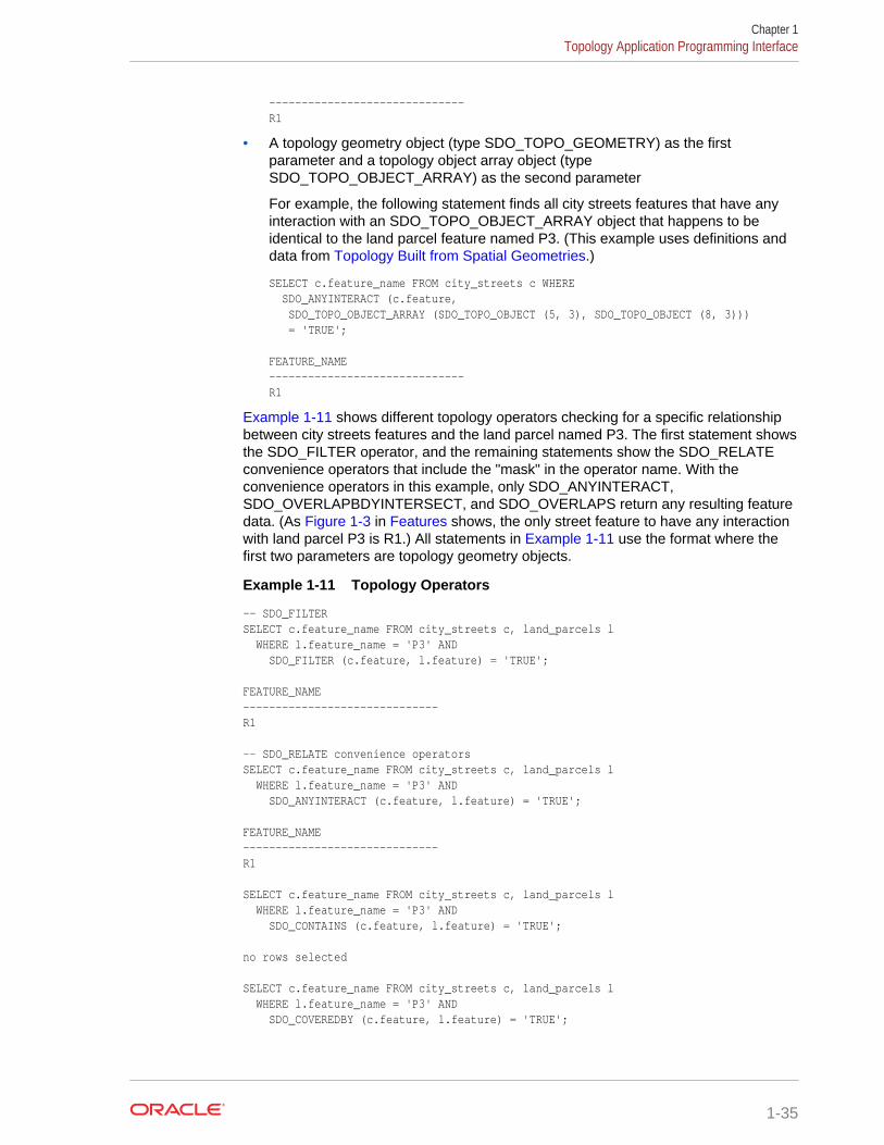
------------------------------ R1
• A topology geometry object (type SDO_TOPO_GEOMETRY) as the firstparameter and a topology object array object (typeSDO_TOPO_OBJECT_ARRAY) as the second parameter
For example, the following statement finds all city streets features that have anyinteraction with an SDO_TOPO_OBJECT_ARRAY object that happens to beidentical to the land parcel feature named P3. (This example uses definitions anddata from Topology Built from Spatial Geometries.)
SELECT c.feature_name FROM city_streets c WHERE SDO_ANYINTERACT (c.feature, SDO_TOPO_OBJECT_ARRAY (SDO_TOPO_OBJECT (5, 3), SDO_TOPO_OBJECT (8, 3))) = 'TRUE'; FEATURE_NAME ------------------------------ R1
Example 1-11 shows different topology operators checking for a specific relationshipbetween city streets features and the land parcel named P3. The first statement showsthe SDO_FILTER operator, and the remaining statements show the SDO_RELATEconvenience operators that include the "mask" in the operator name. With theconvenience operators in this example, only SDO_ANYINTERACT,SDO_OVERLAPBDYINTERSECT, and SDO_OVERLAPS return any resulting featuredata. (As Figure 1-3 in Features shows, the only street feature to have any interactionwith land parcel P3 is R1.) All statements in Example 1-11 use the format where thefirst two parameters are topology geometry objects.
Example 1-11 Topology Operators
-- SDO_FILTERSELECT c.feature_name FROM city_streets c, land_parcels l WHERE l.feature_name = 'P3' AND SDO_FILTER (c.feature, l.feature) = 'TRUE'; FEATURE_NAME ------------------------------ R1 -- SDO_RELATE convenience operatorsSELECT c.feature_name FROM city_streets c, land_parcels l WHERE l.feature_name = 'P3' AND SDO_ANYINTERACT (c.feature, l.feature) = 'TRUE'; FEATURE_NAME ------------------------------ R1 SELECT c.feature_name FROM city_streets c, land_parcels l WHERE l.feature_name = 'P3' AND SDO_CONTAINS (c.feature, l.feature) = 'TRUE'; no rows selected SELECT c.feature_name FROM city_streets c, land_parcels l WHERE l.feature_name = 'P3' AND SDO_COVEREDBY (c.feature, l.feature) = 'TRUE';
Chapter 1Topology Application Programming Interface
1-35
no rows selected SELECT c.feature_name FROM city_streets c, land_parcels l WHERE l.feature_name = 'P3' AND SDO_COVERS (c.feature, l.feature) = 'TRUE'; no rows selected SELECT c.feature_name FROM city_streets c, land_parcels l WHERE l.feature_name = 'P3' AND SDO_EQUAL (c.feature, l.feature) = 'TRUE'; no rows selected SELECT c.feature_name FROM city_streets c, land_parcels l WHERE l.feature_name = 'P3' AND SDO_INSIDE (c.feature, l.feature) = 'TRUE'; no rows selected SELECT c.feature_name FROM city_streets c, land_parcels l WHERE l.feature_name = 'P3' AND SDO_ON (c.feature, l.feature) = 'TRUE'; no rows selected SELECT c.feature_name FROM city_streets c, land_parcels l WHERE l.feature_name = 'P3' AND SDO_OVERLAPBDYINTERSECT (c.feature, l.feature) = 'TRUE'; FEATURE_NAME ------------------------------ R1 SELECT c.feature_name FROM city_streets c, land_parcels l WHERE l.feature_name = 'P3' AND SDO_OVERLAPBDYDISJOINT (c.feature, l.feature) = 'TRUE'; no rows selected SELECT c.feature_name FROM city_streets c, land_parcels l WHERE l.feature_name = 'P3' AND SDO_OVERLAPS (c.feature, l.feature) = 'TRUE'; FEATURE_NAME ------------------------------ R1 SELECT c.feature_name FROM city_streets c, land_parcels l WHERE l.feature_name = 'P3' AND SDO_TOUCH (c.feature, l.feature) = 'TRUE'; no rows selected
See Also:
• Usage Notes for the SDO_TOPO.RELATE function
Chapter 1Topology Application Programming Interface
1-36
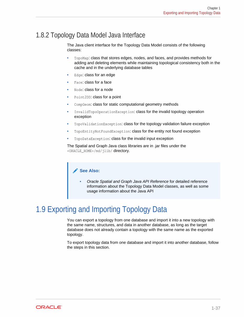
1.8.2 Topology Data Model Java InterfaceThe Java client interface for the Topology Data Model consists of the followingclasses:
• TopoMap: class that stores edges, nodes, and faces, and provides methods foradding and deleting elements while maintaining topological consistency both in thecache and in the underlying database tables
• Edge: class for an edge
• Face: class for a face
• Node: class for a node
• Point2DD: class for a point
• CompGeom: class for static computational geometry methods
• InvalidTopoOperationException: class for the invalid topology operationexception
• TopoValidationException: class for the topology validation failure exception
• TopoEntityNotFoundException: class for the entity not found exception
• TopoDataException: class for the invalid input exception
The Spatial and Graph Java class libraries are in .jar files under the<ORACLE_HOME>/md/jlib/ directory.
See Also:
• Oracle Spatial and Graph Java API Reference for detailed referenceinformation about the Topology Data Model classes, as well as someusage information about the Java API
1.9 Exporting and Importing Topology DataYou can export a topology from one database and import it into a new topology withthe same name, structures, and data in another database, as long as the targetdatabase does not already contain a topology with the same name as the exportedtopology.
To export topology data from one database and import it into another database, followthe steps in this section.
Chapter 1Exporting and Importing Topology Data
1-37

Note:
The steps are required regardless of whether the topology data istransported using transportable tablespaces. (For detailed information abouttransportable tablespaces and transporting tablespaces to other databases,see Oracle Database Administrator's Guide.)
In the database with the topology data to be exported, perform the following actions:
1. Connect to the database as the owner of the topology.
2. Execute the SDO_TOPO.PREPARE_FOR_EXPORT procedure (documented in SDO_TOPO Package Subprograms), to create the topology export informationtable, with a name in the format <topology-name>_EXP$. (This table contains thesame columns as the USER_SDO_TOPO_INFO and ALL_SDO_TOPO_INFOviews. These columns are described in Table 1-8 in xxx_SDO_TOPO_INFOViews.)
For example, preparing the sample CITY_DATA topology for export creates theCITY_DATA_EXP$ table.
3. Export all tables related to the topology, including the feature tables and the<topology-name>_EDGE$, <topology-name>_FACE$, <topology-name>_HISTORY$, <topology-name>_NODE$, <topology-name>_RELATION$,and <topology-name>_EXP$ tables. The names of feature tables (if they exist) arestored in the topology metadata.
This creates a file with the extension .dmp (for example, city_data.dmp).
In the database into which to import the topology data, perform the following actions:
1. Connect to the target database, that is, the database in which to create a topologywith the same name, structures, and data as the topology exported from thesource database. Connect as the user for the schema that is to own the topologyto be created.
2. Ensure that the target database does not already contain a topology with the samename as the topology in the .dmp file.
3. Import the tables from the .dmp file that you created when you exported thetopology data. Specify the indexes=N option.
4. If you have imported the topology tables into a different schema than the one usedfor the topology in the source database, update the values in the OWNER andTABLE_SCHEMA columns in all rows of the <topology-name>_EXP$ table toreflect the table owner and schema names in the current (target) database.
5. Execute the SDO_TOPO.INITIALIZE_AFTER_IMPORT procedure, which createsthe topology and performs other operations, as necessary, to make the topologyready for use.
1.10 Cross-Schema Topology Usage and EditingThis topic contains requirements and guidelines for using and editing topologies whenmultiple database users (schemas) are involved.
• Cross-Schema Topology Usage
Chapter 1Cross-Schema Topology Usage and Editing
1-38
• Cross-Schema Topology Editing
1.10.1 Cross-Schema Topology UsageThe following considerations apply when one user owns a topology and another userowns a topology geometry layer table. In the following, assume that user A owns theCITY_DATA topology and that user B owns the CITY_STREETS topology geometrylayer table.
• The owner of the topology must create the topology and initialize the metadata. Inthis example, user A must perform these actions.
• Only the owner of a topology can add layers to or delete layers from the topology.Therefore, if you add a table owned by another user to a topology, or when youremove such a table from the topology, you must qualify the table name with theschema name. For example, user A could add the CITY_STREETS table ownedby user B to the CITY_DATA topology with the following statement:
EXECUTE SDO_TOPO.ADD_TOPO_GEOMETRY_LAYER('CITY_DATA', 'B.CITY_STREETS', 'FEATURE', 'LINE');
User A could delete the CITY_STREETS table owned by user B from theCITY_DATA topology with the following statement:
EXECUTE SDO_TOPO.DELETE_TOPO_GEOMETRY_LAYER('CITY_DATA', 'B.CITY_STREETS', 'FEATURE');
• The owner of the topology should grant the SELECT or READ privilege on thenode, edge, and face information tables to the owner of the topology geometrylayer table. For example, user A should grant the SELECT privilege on theCITY_DATA_NODE$, CITY_DATA_EDGE$, and CITY_DATA_FACE$ tables touser B.
• The owner of the topology geometry layer table should grant the SELECT andINDEX privileges on that table to the owner of the topology. For example, user Bshould grant the SELECT and INDEX privileges on the CITY_STREETS table touser A.
The owner of the topology geometry layer table should also grant appropriateprivileges to other users that need to access the table. For read-only access, grantthe SELECT privilege on the table to a user; for read/write access, grant theINSERT, SELECT, and UPDATE privileges.
1.10.2 Cross-Schema Topology EditingThe following considerations apply when one user owns a topology and another userwants to edit the topology. In the following, assume that user A owns the CITY_DATAtopology and that user B wants to edit that topology.
• The owner of the topology should grant the following privileges to users who canedit the topology: INSERT, SELECT, and UPDATE on the node, edge, face, andrelationship information tables, and SELECT on the node, edge, and facesequences used to generate ID numbers for the topology primitives. For example,user A could grant the following privileges to user B, where the table names endwith $ and the sequence names end with _S:
GRANT insert,select,update ON city_data_node$ TO b;GRANT insert,select,update ON city_data_edge$ TO b;GRANT insert,select,update ON city_data_face$ TO b;
Chapter 1Cross-Schema Topology Usage and Editing
1-39
GRANT insert,select,update ON city_data_relation$ TO b;GRANT select ON city_data_node_s TO b;GRANT select ON city_data_edge_s TO b;GRANT select ON city_data_face_s TO b;
• When a user who does not own the topology edits that topology, the owner'sschema name should be specified with the topology name in functions andprocedures that accept the topology name as an input parameter. For example,user B should specify the topology as A.CITY_DATA, not just CITY_DATA.
See Also:
• Editing Topologies for information about editing topologies.
1.11 Function-Based Indexes Not SupportedYou cannot create a function-based index on a column of typeSDO_TOPO_GEOMETRY.
(Function-based indexes are explained in Oracle Database Development Guide and Oracle Database Administrator's Guide.)
1.12 Topology Examples (PL/SQL)This topic presents simplified PL/SQL examples that perform Topology Data Modeloperations.
The examples refer to concepts that are explained in this chapter. They useSDO_TOPO and SDO_TOPO_MAP functions and procedures, which are documentedin SDO_TOPO Package Subprograms and SDO_TOPO_MAP Package Subprograms,and the SDO_ANYINTERACT topology operator (see Topology Operators).
Both examples are based on the "city data" topology shown in Figure 1-1 in TopologyData Model Concepts, and the features shown in Figure 1-3 in Features. However, thetopologies created are not identical, because the topology built from Spatial and Graphgeometries (Example 1-13) does not contain all the edges, nodes, and faces that aredefined for the topology build from topology data (Example 1-12).
• Topology Built from Topology Data
• Topology Built from Spatial Geometries
1.12.1 Topology Built from Topology DataExample 1-12 uses a topology built from edge, node, and face data.
Example 1-12 Topology Built from Topology Data
-------------------------------- Main steps for using the Topology Data Model with a topology-- built from edge, node, and face data-------------------------------- 1. Create a topology.-- 2. Load (normally bulk-load) topology data (node, edge, and face tables).
Chapter 1Function-Based Indexes Not Supported
1-40
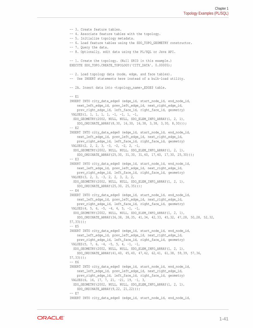
-- 3. Create feature tables.-- 4. Associate feature tables with the topology.-- 5. Initialize topology metadata.-- 6. Load feature tables using the SDO_TOPO_GEOMETRY constructor.-- 7. Query the data.-- 8. Optionally, edit data using the PL/SQL or Java API. -- 1. Create the topology. (Null SRID in this example.)EXECUTE SDO_TOPO.CREATE_TOPOLOGY('CITY_DATA', 0.00005); -- 2. Load topology data (node, edge, and face tables).-- Use INSERT statements here instead of a bulk-load utility. -- 2A. Insert data into <topology_name>_EDGE$ table. -- E1INSERT INTO city_data_edge$ (edge_id, start_node_id, end_node_id, next_left_edge_id, prev_left_edge_id, next_right_edge_id, prev_right_edge_id, left_face_id, right_face_id, geometry) VALUES(1, 1, 1, 1, 1, -1, -1, 1, -1, SDO_GEOMETRY(2002, NULL, NULL, SDO_ELEM_INFO_ARRAY(1, 2, 1), SDO_ORDINATE_ARRAY(8,30, 16,30, 16,38, 3,38, 3,30, 8,30)));-- E2INSERT INTO city_data_edge$ (edge_id, start_node_id, end_node_id, next_left_edge_id, prev_left_edge_id, next_right_edge_id, prev_right_edge_id, left_face_id, right_face_id, geometry) VALUES(2, 2, 2, 3, -3, -2, -2, 2, -1, SDO_GEOMETRY(2002, NULL, NULL, SDO_ELEM_INFO_ARRAY(1, 2, 1), SDO_ORDINATE_ARRAY(25,30, 31,30, 31,40, 17,40, 17,30, 25,30)));-- E3INSERT INTO city_data_edge$ (edge_id, start_node_id, end_node_id, next_left_edge_id, prev_left_edge_id, next_right_edge_id, prev_right_edge_id, left_face_id, right_face_id, geometry) VALUES(3, 2, 3, -3, 2, 2, 3, 2, 2, SDO_GEOMETRY(2002, NULL, NULL, SDO_ELEM_INFO_ARRAY(1, 2, 1), SDO_ORDINATE_ARRAY(25,30, 25,35)));-- E4INSERT INTO city_data_edge$ (edge_id, start_node_id, end_node_id, next_left_edge_id, prev_left_edge_id, next_right_edge_id, prev_right_edge_id, left_face_id, right_face_id, geometry) VALUES(4, 5, 6, -5, -4, 4, 5, -1, -1, SDO_GEOMETRY(2002, NULL, NULL, SDO_ELEM_INFO_ARRAY(1, 2, 1), SDO_ORDINATE_ARRAY(36,38, 38,35, 41,34, 42,33, 45,32, 47,28, 50,28, 52,32,57,33)));-- E5INSERT INTO city_data_edge$ (edge_id, start_node_id, end_node_id, next_left_edge_id, prev_left_edge_id, next_right_edge_id, prev_right_edge_id, left_face_id, right_face_id, geometry) VALUES(5, 7, 6, -4, -5, 5, 4, -1, -1, SDO_GEOMETRY(2002, NULL, NULL, SDO_ELEM_INFO_ARRAY(1, 2, 1), SDO_ORDINATE_ARRAY(41,40, 45,40, 47,42, 62,41, 61,38, 59,39, 57,36,57,33)));-- E6INSERT INTO city_data_edge$ (edge_id, start_node_id, end_node_id, next_left_edge_id, prev_left_edge_id, next_right_edge_id, prev_right_edge_id, left_face_id, right_face_id, geometry) VALUES(6, 16, 17, 7, 21, -21, 19, -1, 3, SDO_GEOMETRY(2002, NULL, NULL, SDO_ELEM_INFO_ARRAY(1, 2, 1), SDO_ORDINATE_ARRAY(9,22, 21,22)));-- E7INSERT INTO city_data_edge$ (edge_id, start_node_id, end_node_id,
Chapter 1Topology Examples (PL/SQL)
1-41
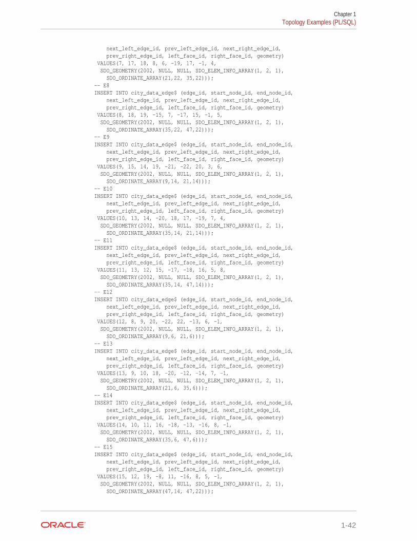
next_left_edge_id, prev_left_edge_id, next_right_edge_id, prev_right_edge_id, left_face_id, right_face_id, geometry) VALUES(7, 17, 18, 8, 6, -19, 17, -1, 4, SDO_GEOMETRY(2002, NULL, NULL, SDO_ELEM_INFO_ARRAY(1, 2, 1), SDO_ORDINATE_ARRAY(21,22, 35,22)));-- E8INSERT INTO city_data_edge$ (edge_id, start_node_id, end_node_id, next_left_edge_id, prev_left_edge_id, next_right_edge_id, prev_right_edge_id, left_face_id, right_face_id, geometry) VALUES(8, 18, 19, -15, 7, -17, 15, -1, 5, SDO_GEOMETRY(2002, NULL, NULL, SDO_ELEM_INFO_ARRAY(1, 2, 1), SDO_ORDINATE_ARRAY(35,22, 47,22)));-- E9INSERT INTO city_data_edge$ (edge_id, start_node_id, end_node_id, next_left_edge_id, prev_left_edge_id, next_right_edge_id, prev_right_edge_id, left_face_id, right_face_id, geometry) VALUES(9, 15, 14, 19, -21, -22, 20, 3, 6, SDO_GEOMETRY(2002, NULL, NULL, SDO_ELEM_INFO_ARRAY(1, 2, 1), SDO_ORDINATE_ARRAY(9,14, 21,14)));-- E10INSERT INTO city_data_edge$ (edge_id, start_node_id, end_node_id, next_left_edge_id, prev_left_edge_id, next_right_edge_id, prev_right_edge_id, left_face_id, right_face_id, geometry) VALUES(10, 13, 14, -20, 18, 17, -19, 7, 4, SDO_GEOMETRY(2002, NULL, NULL, SDO_ELEM_INFO_ARRAY(1, 2, 1), SDO_ORDINATE_ARRAY(35,14, 21,14)));-- E11INSERT INTO city_data_edge$ (edge_id, start_node_id, end_node_id, next_left_edge_id, prev_left_edge_id, next_right_edge_id, prev_right_edge_id, left_face_id, right_face_id, geometry) VALUES(11, 13, 12, 15, -17, -18, 16, 5, 8, SDO_GEOMETRY(2002, NULL, NULL, SDO_ELEM_INFO_ARRAY(1, 2, 1), SDO_ORDINATE_ARRAY(35,14, 47,14)));-- E12INSERT INTO city_data_edge$ (edge_id, start_node_id, end_node_id, next_left_edge_id, prev_left_edge_id, next_right_edge_id, prev_right_edge_id, left_face_id, right_face_id, geometry) VALUES(12, 8, 9, 20, -22, 22, -13, 6, -1, SDO_GEOMETRY(2002, NULL, NULL, SDO_ELEM_INFO_ARRAY(1, 2, 1), SDO_ORDINATE_ARRAY(9,6, 21,6)));-- E13INSERT INTO city_data_edge$ (edge_id, start_node_id, end_node_id, next_left_edge_id, prev_left_edge_id, next_right_edge_id, prev_right_edge_id, left_face_id, right_face_id, geometry) VALUES(13, 9, 10, 18, -20, -12, -14, 7, -1, SDO_GEOMETRY(2002, NULL, NULL, SDO_ELEM_INFO_ARRAY(1, 2, 1), SDO_ORDINATE_ARRAY(21,6, 35,6)));-- E14INSERT INTO city_data_edge$ (edge_id, start_node_id, end_node_id, next_left_edge_id, prev_left_edge_id, next_right_edge_id, prev_right_edge_id, left_face_id, right_face_id, geometry) VALUES(14, 10, 11, 16, -18, -13, -16, 8, -1, SDO_GEOMETRY(2002, NULL, NULL, SDO_ELEM_INFO_ARRAY(1, 2, 1), SDO_ORDINATE_ARRAY(35,6, 47,6)));-- E15INSERT INTO city_data_edge$ (edge_id, start_node_id, end_node_id, next_left_edge_id, prev_left_edge_id, next_right_edge_id, prev_right_edge_id, left_face_id, right_face_id, geometry) VALUES(15, 12, 19, -8, 11, -16, 8, 5, -1, SDO_GEOMETRY(2002, NULL, NULL, SDO_ELEM_INFO_ARRAY(1, 2, 1), SDO_ORDINATE_ARRAY(47,14, 47,22)));
Chapter 1Topology Examples (PL/SQL)
1-42
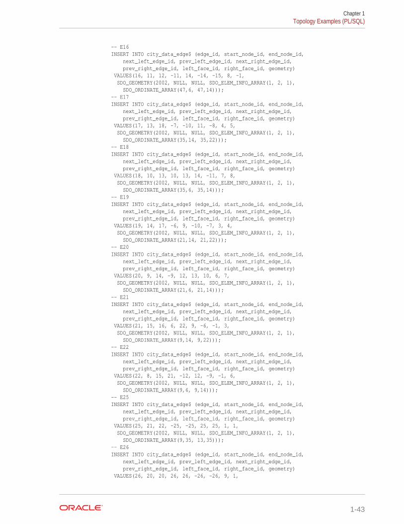
-- E16INSERT INTO city_data_edge$ (edge_id, start_node_id, end_node_id, next_left_edge_id, prev_left_edge_id, next_right_edge_id, prev_right_edge_id, left_face_id, right_face_id, geometry) VALUES(16, 11, 12, -11, 14, -14, -15, 8, -1, SDO_GEOMETRY(2002, NULL, NULL, SDO_ELEM_INFO_ARRAY(1, 2, 1), SDO_ORDINATE_ARRAY(47,6, 47,14)));-- E17INSERT INTO city_data_edge$ (edge_id, start_node_id, end_node_id, next_left_edge_id, prev_left_edge_id, next_right_edge_id, prev_right_edge_id, left_face_id, right_face_id, geometry) VALUES(17, 13, 18, -7, -10, 11, -8, 4, 5, SDO_GEOMETRY(2002, NULL, NULL, SDO_ELEM_INFO_ARRAY(1, 2, 1), SDO_ORDINATE_ARRAY(35,14, 35,22)));-- E18INSERT INTO city_data_edge$ (edge_id, start_node_id, end_node_id, next_left_edge_id, prev_left_edge_id, next_right_edge_id, prev_right_edge_id, left_face_id, right_face_id, geometry) VALUES(18, 10, 13, 10, 13, 14, -11, 7, 8, SDO_GEOMETRY(2002, NULL, NULL, SDO_ELEM_INFO_ARRAY(1, 2, 1), SDO_ORDINATE_ARRAY(35,6, 35,14)));-- E19INSERT INTO city_data_edge$ (edge_id, start_node_id, end_node_id, next_left_edge_id, prev_left_edge_id, next_right_edge_id, prev_right_edge_id, left_face_id, right_face_id, geometry) VALUES(19, 14, 17, -6, 9, -10, -7, 3, 4, SDO_GEOMETRY(2002, NULL, NULL, SDO_ELEM_INFO_ARRAY(1, 2, 1), SDO_ORDINATE_ARRAY(21,14, 21,22)));-- E20INSERT INTO city_data_edge$ (edge_id, start_node_id, end_node_id, next_left_edge_id, prev_left_edge_id, next_right_edge_id, prev_right_edge_id, left_face_id, right_face_id, geometry) VALUES(20, 9, 14, -9, 12, 13, 10, 6, 7, SDO_GEOMETRY(2002, NULL, NULL, SDO_ELEM_INFO_ARRAY(1, 2, 1), SDO_ORDINATE_ARRAY(21,6, 21,14)));-- E21INSERT INTO city_data_edge$ (edge_id, start_node_id, end_node_id, next_left_edge_id, prev_left_edge_id, next_right_edge_id, prev_right_edge_id, left_face_id, right_face_id, geometry) VALUES(21, 15, 16, 6, 22, 9, -6, -1, 3, SDO_GEOMETRY(2002, NULL, NULL, SDO_ELEM_INFO_ARRAY(1, 2, 1), SDO_ORDINATE_ARRAY(9,14, 9,22)));-- E22INSERT INTO city_data_edge$ (edge_id, start_node_id, end_node_id, next_left_edge_id, prev_left_edge_id, next_right_edge_id, prev_right_edge_id, left_face_id, right_face_id, geometry) VALUES(22, 8, 15, 21, -12, 12, -9, -1, 6, SDO_GEOMETRY(2002, NULL, NULL, SDO_ELEM_INFO_ARRAY(1, 2, 1), SDO_ORDINATE_ARRAY(9,6, 9,14)));-- E25INSERT INTO city_data_edge$ (edge_id, start_node_id, end_node_id, next_left_edge_id, prev_left_edge_id, next_right_edge_id, prev_right_edge_id, left_face_id, right_face_id, geometry) VALUES(25, 21, 22, -25, -25, 25, 25, 1, 1, SDO_GEOMETRY(2002, NULL, NULL, SDO_ELEM_INFO_ARRAY(1, 2, 1), SDO_ORDINATE_ARRAY(9,35, 13,35)));-- E26INSERT INTO city_data_edge$ (edge_id, start_node_id, end_node_id, next_left_edge_id, prev_left_edge_id, next_right_edge_id, prev_right_edge_id, left_face_id, right_face_id, geometry) VALUES(26, 20, 20, 26, 26, -26, -26, 9, 1,
Chapter 1Topology Examples (PL/SQL)
1-43
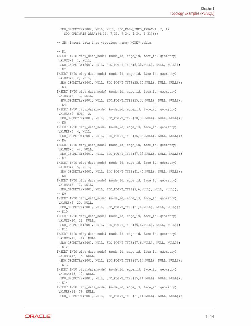
SDO_GEOMETRY(2002, NULL, NULL, SDO_ELEM_INFO_ARRAY(1, 2, 1), SDO_ORDINATE_ARRAY(4,31, 7,31, 7,34, 4,34, 4,31))); -- 2B. Insert data into <topology_name>_NODE$ table. -- N1INSERT INTO city_data_node$ (node_id, edge_id, face_id, geometry) VALUES(1, 1, NULL, SDO_GEOMETRY(2001, NULL, SDO_POINT_TYPE(8,30,NULL), NULL, NULL));-- N2INSERT INTO city_data_node$ (node_id, edge_id, face_id, geometry) VALUES(2, 2, NULL, SDO_GEOMETRY(2001, NULL, SDO_POINT_TYPE(25,30,NULL), NULL, NULL));-- N3INSERT INTO city_data_node$ (node_id, edge_id, face_id, geometry) VALUES(3, -3, NULL, SDO_GEOMETRY(2001, NULL, SDO_POINT_TYPE(25,35,NULL), NULL, NULL));-- N4INSERT INTO city_data_node$ (node_id, edge_id, face_id, geometry) VALUES(4, NULL, 2, SDO_GEOMETRY(2001, NULL, SDO_POINT_TYPE(20,37,NULL), NULL, NULL));-- N5INSERT INTO city_data_node$ (node_id, edge_id, face_id, geometry) VALUES(5, 4, NULL, SDO_GEOMETRY(2001, NULL, SDO_POINT_TYPE(36,38,NULL), NULL, NULL));-- N6INSERT INTO city_data_node$ (node_id, edge_id, face_id, geometry) VALUES(6, -4, NULL, SDO_GEOMETRY(2001, NULL, SDO_POINT_TYPE(57,33,NULL), NULL, NULL));-- N7INSERT INTO city_data_node$ (node_id, edge_id, face_id, geometry) VALUES(7, 5, NULL, SDO_GEOMETRY(2001, NULL, SDO_POINT_TYPE(41,40,NULL), NULL, NULL));-- N8INSERT INTO city_data_node$ (node_id, edge_id, face_id, geometry) VALUES(8, 12, NULL, SDO_GEOMETRY(2001, NULL, SDO_POINT_TYPE(9,6,NULL), NULL, NULL));-- N9INSERT INTO city_data_node$ (node_id, edge_id, face_id, geometry) VALUES(9, 20, NULL, SDO_GEOMETRY(2001, NULL, SDO_POINT_TYPE(21,6,NULL), NULL, NULL));-- N10INSERT INTO city_data_node$ (node_id, edge_id, face_id, geometry) VALUES(10, 18, NULL, SDO_GEOMETRY(2001, NULL, SDO_POINT_TYPE(35,6,NULL), NULL, NULL));-- N11INSERT INTO city_data_node$ (node_id, edge_id, face_id, geometry) VALUES(11, -14, NULL, SDO_GEOMETRY(2001, NULL, SDO_POINT_TYPE(47,6,NULL), NULL, NULL));-- N12INSERT INTO city_data_node$ (node_id, edge_id, face_id, geometry) VALUES(12, 15, NULL, SDO_GEOMETRY(2001, NULL, SDO_POINT_TYPE(47,14,NULL), NULL, NULL));-- N13INSERT INTO city_data_node$ (node_id, edge_id, face_id, geometry) VALUES(13, 17, NULL, SDO_GEOMETRY(2001, NULL, SDO_POINT_TYPE(35,14,NULL), NULL, NULL));-- N14INSERT INTO city_data_node$ (node_id, edge_id, face_id, geometry) VALUES(14, 19, NULL, SDO_GEOMETRY(2001, NULL, SDO_POINT_TYPE(21,14,NULL), NULL, NULL));
Chapter 1Topology Examples (PL/SQL)
1-44
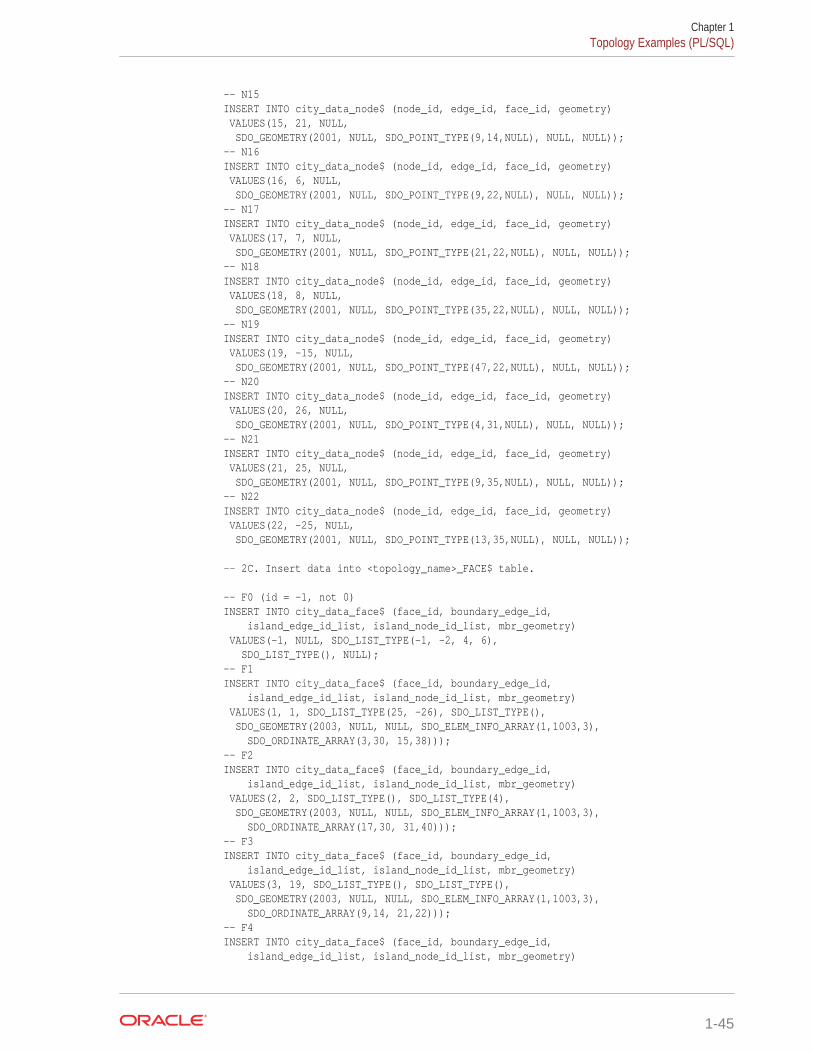
-- N15INSERT INTO city_data_node$ (node_id, edge_id, face_id, geometry) VALUES(15, 21, NULL, SDO_GEOMETRY(2001, NULL, SDO_POINT_TYPE(9,14,NULL), NULL, NULL));-- N16INSERT INTO city_data_node$ (node_id, edge_id, face_id, geometry) VALUES(16, 6, NULL, SDO_GEOMETRY(2001, NULL, SDO_POINT_TYPE(9,22,NULL), NULL, NULL));-- N17INSERT INTO city_data_node$ (node_id, edge_id, face_id, geometry) VALUES(17, 7, NULL, SDO_GEOMETRY(2001, NULL, SDO_POINT_TYPE(21,22,NULL), NULL, NULL));-- N18INSERT INTO city_data_node$ (node_id, edge_id, face_id, geometry) VALUES(18, 8, NULL, SDO_GEOMETRY(2001, NULL, SDO_POINT_TYPE(35,22,NULL), NULL, NULL));-- N19INSERT INTO city_data_node$ (node_id, edge_id, face_id, geometry) VALUES(19, -15, NULL, SDO_GEOMETRY(2001, NULL, SDO_POINT_TYPE(47,22,NULL), NULL, NULL));-- N20INSERT INTO city_data_node$ (node_id, edge_id, face_id, geometry) VALUES(20, 26, NULL, SDO_GEOMETRY(2001, NULL, SDO_POINT_TYPE(4,31,NULL), NULL, NULL));-- N21INSERT INTO city_data_node$ (node_id, edge_id, face_id, geometry) VALUES(21, 25, NULL, SDO_GEOMETRY(2001, NULL, SDO_POINT_TYPE(9,35,NULL), NULL, NULL));-- N22INSERT INTO city_data_node$ (node_id, edge_id, face_id, geometry) VALUES(22, -25, NULL, SDO_GEOMETRY(2001, NULL, SDO_POINT_TYPE(13,35,NULL), NULL, NULL)); -- 2C. Insert data into <topology_name>_FACE$ table. -- F0 (id = -1, not 0)INSERT INTO city_data_face$ (face_id, boundary_edge_id, island_edge_id_list, island_node_id_list, mbr_geometry) VALUES(-1, NULL, SDO_LIST_TYPE(-1, -2, 4, 6), SDO_LIST_TYPE(), NULL);-- F1INSERT INTO city_data_face$ (face_id, boundary_edge_id, island_edge_id_list, island_node_id_list, mbr_geometry) VALUES(1, 1, SDO_LIST_TYPE(25, -26), SDO_LIST_TYPE(), SDO_GEOMETRY(2003, NULL, NULL, SDO_ELEM_INFO_ARRAY(1,1003,3), SDO_ORDINATE_ARRAY(3,30, 15,38)));-- F2INSERT INTO city_data_face$ (face_id, boundary_edge_id, island_edge_id_list, island_node_id_list, mbr_geometry) VALUES(2, 2, SDO_LIST_TYPE(), SDO_LIST_TYPE(4), SDO_GEOMETRY(2003, NULL, NULL, SDO_ELEM_INFO_ARRAY(1,1003,3), SDO_ORDINATE_ARRAY(17,30, 31,40)));-- F3INSERT INTO city_data_face$ (face_id, boundary_edge_id, island_edge_id_list, island_node_id_list, mbr_geometry) VALUES(3, 19, SDO_LIST_TYPE(), SDO_LIST_TYPE(), SDO_GEOMETRY(2003, NULL, NULL, SDO_ELEM_INFO_ARRAY(1,1003,3), SDO_ORDINATE_ARRAY(9,14, 21,22)));-- F4INSERT INTO city_data_face$ (face_id, boundary_edge_id, island_edge_id_list, island_node_id_list, mbr_geometry)
Chapter 1Topology Examples (PL/SQL)
1-45
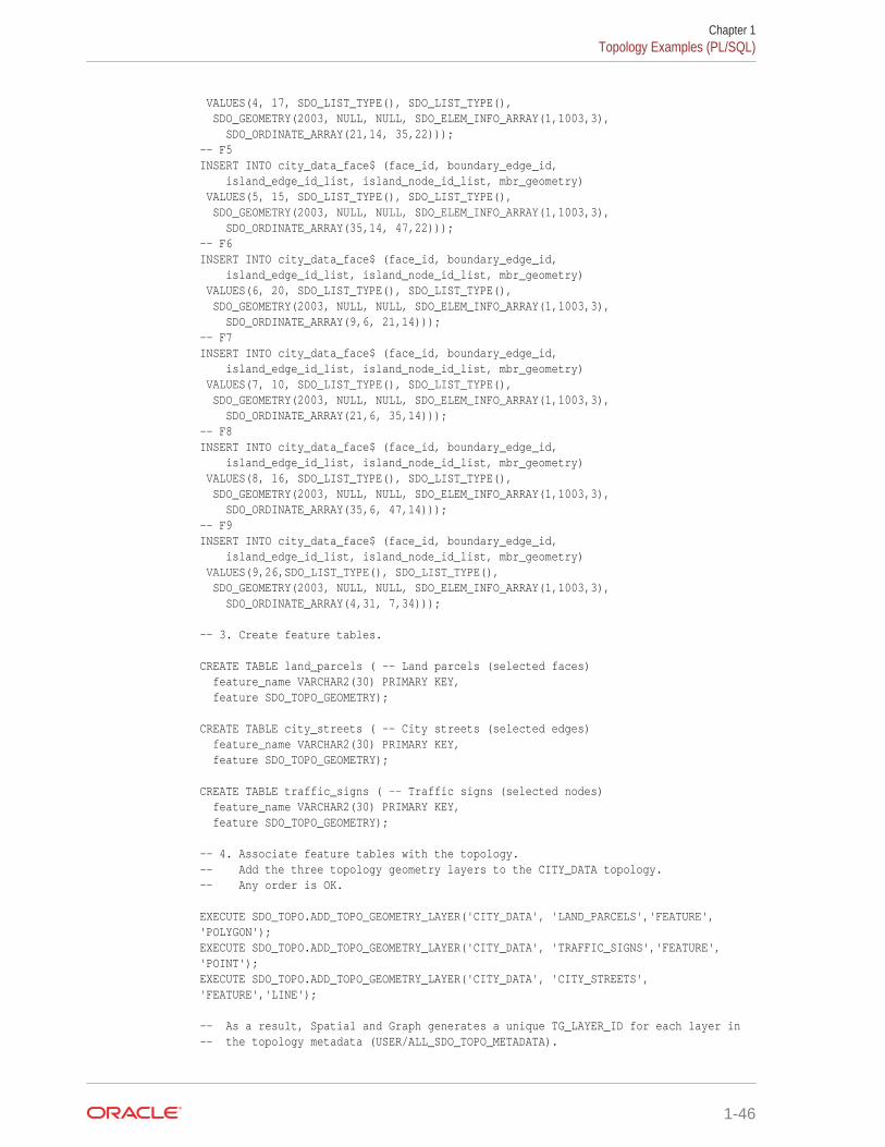
VALUES(4, 17, SDO_LIST_TYPE(), SDO_LIST_TYPE(), SDO_GEOMETRY(2003, NULL, NULL, SDO_ELEM_INFO_ARRAY(1,1003,3), SDO_ORDINATE_ARRAY(21,14, 35,22)));-- F5INSERT INTO city_data_face$ (face_id, boundary_edge_id, island_edge_id_list, island_node_id_list, mbr_geometry) VALUES(5, 15, SDO_LIST_TYPE(), SDO_LIST_TYPE(), SDO_GEOMETRY(2003, NULL, NULL, SDO_ELEM_INFO_ARRAY(1,1003,3), SDO_ORDINATE_ARRAY(35,14, 47,22)));-- F6INSERT INTO city_data_face$ (face_id, boundary_edge_id, island_edge_id_list, island_node_id_list, mbr_geometry) VALUES(6, 20, SDO_LIST_TYPE(), SDO_LIST_TYPE(), SDO_GEOMETRY(2003, NULL, NULL, SDO_ELEM_INFO_ARRAY(1,1003,3), SDO_ORDINATE_ARRAY(9,6, 21,14)));-- F7INSERT INTO city_data_face$ (face_id, boundary_edge_id, island_edge_id_list, island_node_id_list, mbr_geometry) VALUES(7, 10, SDO_LIST_TYPE(), SDO_LIST_TYPE(), SDO_GEOMETRY(2003, NULL, NULL, SDO_ELEM_INFO_ARRAY(1,1003,3), SDO_ORDINATE_ARRAY(21,6, 35,14)));-- F8INSERT INTO city_data_face$ (face_id, boundary_edge_id, island_edge_id_list, island_node_id_list, mbr_geometry) VALUES(8, 16, SDO_LIST_TYPE(), SDO_LIST_TYPE(), SDO_GEOMETRY(2003, NULL, NULL, SDO_ELEM_INFO_ARRAY(1,1003,3), SDO_ORDINATE_ARRAY(35,6, 47,14)));-- F9INSERT INTO city_data_face$ (face_id, boundary_edge_id, island_edge_id_list, island_node_id_list, mbr_geometry) VALUES(9,26,SDO_LIST_TYPE(), SDO_LIST_TYPE(), SDO_GEOMETRY(2003, NULL, NULL, SDO_ELEM_INFO_ARRAY(1,1003,3), SDO_ORDINATE_ARRAY(4,31, 7,34))); -- 3. Create feature tables. CREATE TABLE land_parcels ( -- Land parcels (selected faces) feature_name VARCHAR2(30) PRIMARY KEY, feature SDO_TOPO_GEOMETRY); CREATE TABLE city_streets ( -- City streets (selected edges) feature_name VARCHAR2(30) PRIMARY KEY, feature SDO_TOPO_GEOMETRY); CREATE TABLE traffic_signs ( -- Traffic signs (selected nodes) feature_name VARCHAR2(30) PRIMARY KEY, feature SDO_TOPO_GEOMETRY); -- 4. Associate feature tables with the topology.-- Add the three topology geometry layers to the CITY_DATA topology.-- Any order is OK. EXECUTE SDO_TOPO.ADD_TOPO_GEOMETRY_LAYER('CITY_DATA', 'LAND_PARCELS','FEATURE', 'POLYGON');EXECUTE SDO_TOPO.ADD_TOPO_GEOMETRY_LAYER('CITY_DATA', 'TRAFFIC_SIGNS','FEATURE', 'POINT');EXECUTE SDO_TOPO.ADD_TOPO_GEOMETRY_LAYER('CITY_DATA', 'CITY_STREETS', 'FEATURE','LINE'); -- As a result, Spatial and Graph generates a unique TG_LAYER_ID for each layer in -- the topology metadata (USER/ALL_SDO_TOPO_METADATA).
Chapter 1Topology Examples (PL/SQL)
1-46
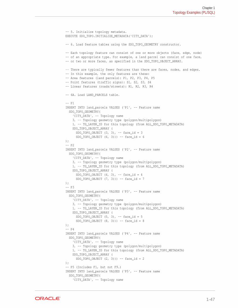
-- 5. Initialize topology metadata.EXECUTE SDO_TOPO.INITIALIZE_METADATA('CITY_DATA'); -- 6. Load feature tables using the SDO_TOPO_GEOMETRY constructor. -- Each topology feature can consist of one or more objects (face, edge, node)-- of an appropriate type. For example, a land parcel can consist of one face,-- or two or more faces, as specified in the SDO_TOPO_OBJECT_ARRAY. -- There are typically fewer features than there are faces, nodes, and edges.-- In this example, the only features are these:-- Area features (land parcels): P1, P2, P3, P4, P5-- Point features (traffic signs): S1, S2, S3, S4-- Linear features (roads/streets): R1, R2, R3, R4
-- 6A. Load LAND_PARCELS table. -- P1INSERT INTO land_parcels VALUES ('P1', -- Feature name SDO_TOPO_GEOMETRY( 'CITY_DATA', -- Topology name 3, -- Topology geometry type (polygon/multipolygon) 1, -- TG_LAYER_ID for this topology (from ALL_SDO_TOPO_METADATA) SDO_TOPO_OBJECT_ARRAY ( SDO_TOPO_OBJECT (3, 3), -- face_id = 3 SDO_TOPO_OBJECT (6, 3))) -- face_id = 6);-- P2INSERT INTO land_parcels VALUES ('P2', -- Feature name SDO_TOPO_GEOMETRY( 'CITY_DATA', -- Topology name 3, -- Topology geometry type (polygon/multipolygon) 1, -- TG_LAYER_ID for this topology (from ALL_SDO_TOPO_METADATA) SDO_TOPO_OBJECT_ARRAY ( SDO_TOPO_OBJECT (4, 3), -- face_id = 4 SDO_TOPO_OBJECT (7, 3))) -- face_id = 7);-- P3INSERT INTO land_parcels VALUES ('P3', -- Feature name SDO_TOPO_GEOMETRY( 'CITY_DATA', -- Topology name 3, -- Topology geometry type (polygon/multipolygon) 1, -- TG_LAYER_ID for this topology (from ALL_SDO_TOPO_METADATA) SDO_TOPO_OBJECT_ARRAY ( SDO_TOPO_OBJECT (5, 3), -- face_id = 5 SDO_TOPO_OBJECT (8, 3))) -- face_id = 8);-- P4INSERT INTO land_parcels VALUES ('P4', -- Feature name SDO_TOPO_GEOMETRY( 'CITY_DATA', -- Topology name 3, -- Topology geometry type (polygon/multipolygon) 1, -- TG_LAYER_ID for this topology (from ALL_SDO_TOPO_METADATA) SDO_TOPO_OBJECT_ARRAY ( SDO_TOPO_OBJECT (2, 3))) -- face_id = 2);-- P5 (Includes F1, but not F9.)INSERT INTO land_parcels VALUES ('P5', -- Feature name SDO_TOPO_GEOMETRY( 'CITY_DATA', -- Topology name
Chapter 1Topology Examples (PL/SQL)
1-47

3, -- Topology geometry type (polygon/multipolygon) 1, -- TG_LAYER_ID for this topology (from ALL_SDO_TOPO_METADATA) SDO_TOPO_OBJECT_ARRAY ( SDO_TOPO_OBJECT (1, 3))) -- face_id = 1); -- 6B. Load TRAFFIC_SIGNS table. -- S1INSERT INTO traffic_signs VALUES ('S1', -- Feature name SDO_TOPO_GEOMETRY( 'CITY_DATA', -- Topology name 1, -- Topology geometry type (point) 2, -- TG_LAYER_ID for this topology (from ALL_SDO_TOPO_METADATA) SDO_TOPO_OBJECT_ARRAY ( SDO_TOPO_OBJECT (14, 1))) -- node_id = 14);-- S2INSERT INTO traffic_signs VALUES ('S2', -- Feature name SDO_TOPO_GEOMETRY( 'CITY_DATA', -- Topology name 1, -- Topology geometry type (point) 2, -- TG_LAYER_ID for this topology (from ALL_SDO_TOPO_METADATA) SDO_TOPO_OBJECT_ARRAY ( SDO_TOPO_OBJECT (13, 1))) -- node_id = 13);-- S3INSERT INTO traffic_signs VALUES ('S3', -- Feature name SDO_TOPO_GEOMETRY( 'CITY_DATA', -- Topology name 1, -- Topology geometry type (point) 2, -- TG_LAYER_ID for this topology (from ALL_SDO_TOPO_METADATA) SDO_TOPO_OBJECT_ARRAY ( SDO_TOPO_OBJECT (6, 1))) -- node_id = 6);-- S4INSERT INTO traffic_signs VALUES ('S4', -- Feature name SDO_TOPO_GEOMETRY( 'CITY_DATA', -- Topology name 1, -- Topology geometry type (point) 2, -- TG_LAYER_ID for this topology (from ALL_SDO_TOPO_METADATA) SDO_TOPO_OBJECT_ARRAY ( SDO_TOPO_OBJECT (4, 1))) -- node_id = 4); -- 6C. Load CITY_STREETS table.-- (Note: "R" in feature names is for "Road", because "S" is used for signs.) -- R1INSERT INTO city_streets VALUES ('R1', -- Feature name SDO_TOPO_GEOMETRY( 'CITY_DATA', -- Topology name 2, -- Topology geometry type (line string) 3, -- TG_LAYER_ID for this topology (from ALL_SDO_TOPO_METADATA) SDO_TOPO_OBJECT_ARRAY ( SDO_TOPO_OBJECT (9, 2), SDO_TOPO_OBJECT (-10, 2), SDO_TOPO_OBJECT (11, 2))) -- edge_ids = 9, -10, 11);-- R2INSERT INTO city_streets VALUES ('R2', -- Feature name
Chapter 1Topology Examples (PL/SQL)
1-48
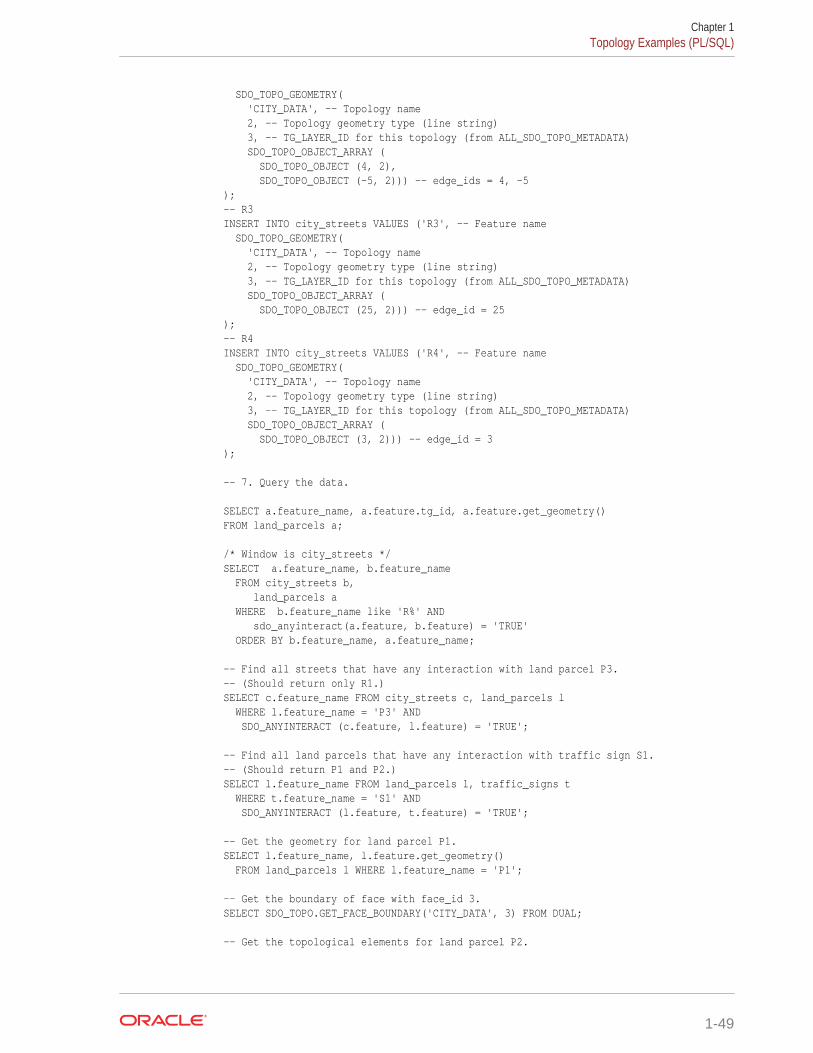
SDO_TOPO_GEOMETRY( 'CITY_DATA', -- Topology name 2, -- Topology geometry type (line string) 3, -- TG_LAYER_ID for this topology (from ALL_SDO_TOPO_METADATA) SDO_TOPO_OBJECT_ARRAY ( SDO_TOPO_OBJECT (4, 2), SDO_TOPO_OBJECT (-5, 2))) -- edge_ids = 4, -5);-- R3INSERT INTO city_streets VALUES ('R3', -- Feature name SDO_TOPO_GEOMETRY( 'CITY_DATA', -- Topology name 2, -- Topology geometry type (line string) 3, -- TG_LAYER_ID for this topology (from ALL_SDO_TOPO_METADATA) SDO_TOPO_OBJECT_ARRAY ( SDO_TOPO_OBJECT (25, 2))) -- edge_id = 25);-- R4INSERT INTO city_streets VALUES ('R4', -- Feature name SDO_TOPO_GEOMETRY( 'CITY_DATA', -- Topology name 2, -- Topology geometry type (line string) 3, -- TG_LAYER_ID for this topology (from ALL_SDO_TOPO_METADATA) SDO_TOPO_OBJECT_ARRAY ( SDO_TOPO_OBJECT (3, 2))) -- edge_id = 3); -- 7. Query the data. SELECT a.feature_name, a.feature.tg_id, a.feature.get_geometry()FROM land_parcels a; /* Window is city_streets */SELECT a.feature_name, b.feature_name FROM city_streets b, land_parcels a WHERE b.feature_name like 'R%' AND sdo_anyinteract(a.feature, b.feature) = 'TRUE' ORDER BY b.feature_name, a.feature_name; -- Find all streets that have any interaction with land parcel P3.-- (Should return only R1.)SELECT c.feature_name FROM city_streets c, land_parcels l WHERE l.feature_name = 'P3' AND SDO_ANYINTERACT (c.feature, l.feature) = 'TRUE'; -- Find all land parcels that have any interaction with traffic sign S1.-- (Should return P1 and P2.)SELECT l.feature_name FROM land_parcels l, traffic_signs t WHERE t.feature_name = 'S1' AND SDO_ANYINTERACT (l.feature, t.feature) = 'TRUE'; -- Get the geometry for land parcel P1.SELECT l.feature_name, l.feature.get_geometry() FROM land_parcels l WHERE l.feature_name = 'P1'; -- Get the boundary of face with face_id 3.SELECT SDO_TOPO.GET_FACE_BOUNDARY('CITY_DATA', 3) FROM DUAL; -- Get the topological elements for land parcel P2.
Chapter 1Topology Examples (PL/SQL)
1-49
-- CITY_DATA layer, land parcels (tg_ layer_id = 1), parcel P2 (tg_id = 2)SELECT SDO_TOPO.GET_TOPO_OBJECTS('CITY_DATA', 1, 2) FROM DUAL;
1.12.2 Topology Built from Spatial GeometriesExample 1-13 uses a topology built from Oracle Spatial and Graph geometry data.
Example 1-13 Topology Built from Spatial Geometries
-------------------------------- Main steps for using the Topology Data Model with a topology-- built from Spatial and Graph geometry data-------------------------------- 1. Create the topology.-- 2. Insert the universe face (F0). (id = -1, not 0)-- 3. Create feature tables.-- 4. Associate feature tables with the topology.-- 5. Initialize topology metadata.-- 6. Create a TopoMap object and load the whole topology into -- cache for updating.-- 7. Load feature tables, inserting data from the spatial tables and -- using SDO_TOPO_MAP.CREATE_FEATURE.-- 8. Query the data.-- 9. Optionally, edit the data using the PL/SQL or Java API. -- Preliminary work for this example (things normally done to use-- data with Oracle Spatial and Graph): -- * Create the spatial tables.-- * Update the spatial metadata (USER_SDO_GEOM_METADATA).-- * Load data into the spatial tables.-- * Validate the spatial data (validate the layers).-- * Create the spatial indexes. -- Create spatial tables of geometry features: names and geometries. CREATE TABLE city_streets_geom ( -- City streets/roads name VARCHAR2(30) PRIMARY KEY, geometry SDO_GEOMETRY); CREATE TABLE traffic_signs_geom ( -- Traffic signs name VARCHAR2(30) PRIMARY KEY, geometry SDO_GEOMETRY); CREATE TABLE land_parcels_geom ( -- Land parcels name VARCHAR2(30) PRIMARY KEY, geometry SDO_GEOMETRY); INSERT INTO user_sdo_geom_metadata (TABLE_NAME, COLUMN_NAME, DIMINFO, SRID) VALUES ( 'CITY_STREETS_GEOM', 'GEOMETRY', SDO_DIM_ARRAY( SDO_DIM_ELEMENT('X', 0, 65, 0.005), SDO_DIM_ELEMENT('Y', 0, 45, 0.005) ), NULL -- SRID );
Chapter 1Topology Examples (PL/SQL)
1-50
INSERT INTO user_sdo_geom_metadata (TABLE_NAME, COLUMN_NAME, DIMINFO, SRID) VALUES ( 'TRAFFIC_SIGNS_GEOM', 'GEOMETRY', SDO_DIM_ARRAY( SDO_DIM_ELEMENT('X', 0, 65, 0.005), SDO_DIM_ELEMENT('Y', 0, 45, 0.005) ), NULL -- SRID ); INSERT INTO user_sdo_geom_metadata (TABLE_NAME, COLUMN_NAME, DIMINFO, SRID) VALUES ( 'LAND_PARCELS_GEOM', 'GEOMETRY', SDO_DIM_ARRAY( SDO_DIM_ELEMENT('X', 0, 65, 0.005), SDO_DIM_ELEMENT('Y', 0, 45, 0.005) ), NULL -- SRID ); -- Load these tables (names and geometries for city streets/roads,-- traffic signs, and land parcels). -- Insert data into city street line geometries. -- R1 INSERT INTO city_streets_geom VALUES('R1', SDO_GEOMETRY(2002, NULL, NULL, SDO_ELEM_INFO_ARRAY(1, 2, 1), SDO_ORDINATE_ARRAY(9,14, 21,14, 35,14, 47,14))); -- R2INSERT INTO city_streets_geom VALUES('R2', SDO_GEOMETRY(2002, NULL, NULL, SDO_ELEM_INFO_ARRAY(1, 2, 1), SDO_ORDINATE_ARRAY(36,38, 38,35, 41,34, 42,33, 45,32, 47,28, 50,28, 52,32,57,33, 57,36, 59,39, 61,38, 62,41, 47,42, 45,40, 41,40))); -- R3INSERT INTO city_streets_geom VALUES('R3', SDO_GEOMETRY(2002, NULL, NULL, SDO_ELEM_INFO_ARRAY(1, 2, 1), SDO_ORDINATE_ARRAY(9,35, 13,35))); -- R4INSERT INTO city_streets_geom VALUES('R4', SDO_GEOMETRY(2002, NULL, NULL, SDO_ELEM_INFO_ARRAY(1, 2, 1), SDO_ORDINATE_ARRAY(25,30, 25,35))); -- Insert data into traffic sign point geometries. -- S1INSERT INTO traffic_signs_geom VALUES('S1',
Chapter 1Topology Examples (PL/SQL)
1-51
SDO_GEOMETRY(2001, NULL, SDO_POINT_TYPE(21,14,NULL), NULL, NULL)); -- S2INSERT INTO traffic_signs_geom VALUES('S2', SDO_GEOMETRY(2001, NULL, SDO_POINT_TYPE(35,14,NULL), NULL, NULL)); -- S3INSERT INTO traffic_signs_geom VALUES('S3', SDO_GEOMETRY(2001, NULL, SDO_POINT_TYPE(57,33,NULL), NULL, NULL)); -- S4INSERT INTO traffic_signs_geom VALUES('S4', SDO_GEOMETRY(2001, NULL, SDO_POINT_TYPE(20,37,NULL), NULL, NULL)); -- Insert data into land parcel polygon geometries. -- P1INSERT INTO land_parcels_geom VALUES('P1', SDO_GEOMETRY(2003, NULL, NULL, SDO_ELEM_INFO_ARRAY(1, 1003, 1), SDO_ORDINATE_ARRAY(9,6, 21,6, 21,14, 21,22, 9,22, 9,14, 9,6))); -- P2INSERT INTO land_parcels_geom VALUES('P2', SDO_GEOMETRY(2003, NULL, NULL, SDO_ELEM_INFO_ARRAY(1,1003,1), SDO_ORDINATE_ARRAY(21,6, 35,6, 35,14, 35,22, 21,22, 21,14, 21,6))); -- P3INSERT INTO land_parcels_geom VALUES('P3', SDO_GEOMETRY(2003, NULL, NULL, SDO_ELEM_INFO_ARRAY(1,1003,1), SDO_ORDINATE_ARRAY(35,6, 47,6, 47,14, 47,22, 35,22, 35,14, 35,6))); -- P4INSERT INTO land_parcels_geom VALUES('P4', SDO_GEOMETRY(2003, NULL, NULL, SDO_ELEM_INFO_ARRAY(1,1003,1), SDO_ORDINATE_ARRAY(17,30, 31,30, 31,40, 17,40, 17,30))); -- P5 (polygon with a hole; exterior ring and one interior ring)INSERT INTO land_parcels_geom VALUES('P5', SDO_GEOMETRY(2003, NULL, NULL, SDO_ELEM_INFO_ARRAY(1,1003,1, 11,2003,1), SDO_ORDINATE_ARRAY(3,30, 16,30, 16,38, 3,38, 3,30, 4,31, 4,34, 7,34, 7,31, 4,31))); -- Validate the layers.create table val_results (sdo_rowid ROWID, result VARCHAR2(2000));call SDO_GEOM.VALIDATE_LAYER_WITH_CONTEXT('CITY_STREETS_GEOM','GEOMETRY','VAL_RESULTS');SELECT * from val_results;truncate table val_results;call SDO_GEOM.VALIDATE_LAYER_WITH_CONTEXT('TRAFFIC_SIGNS_GEOM','GEOMETRY','VAL_RESULTS');SELECT * from val_results;truncate table val_results;call SDO_GEOM.VALIDATE_LAYER_WITH_CONTEXT('LAND_PARCELS_GEOM','GEOMETRY','VAL_RESULTS');SELECT * from val_results;drop table val_results; -- Create the spatial indexes.CREATE INDEX city_streets_geom_idx ON city_streets_geom(geometry) INDEXTYPE IS MDSYS.SPATIAL_INDEX;CREATE INDEX traffic_signs_geom_idx ON traffic_signs_geom(geometry)
Chapter 1Topology Examples (PL/SQL)
1-52
INDEXTYPE IS MDSYS.SPATIAL_INDEX;CREATE INDEX land_parcels_geom_idx ON land_parcels_geom(geometry) INDEXTYPE IS MDSYS.SPATIAL_INDEX; -- Start the main steps for using the Topology Data Model with a-- topology built from spatial geometry data. -- 1. Create the topology. (Null SRID in this example.)EXECUTE SDO_TOPO.CREATE_TOPOLOGY('CITY_DATA', 0.00005); -- 2. Insert the universe face (F0). (id = -1, not 0)INSERT INTO CITY_DATA_FACE$ values ( -1, NULL, SDO_LIST_TYPE(), SDO_LIST_TYPE(), NULL); COMMIT; -- 3. Create feature tables. CREATE TABLE city_streets ( -- City streets/roads feature_name VARCHAR2(30) PRIMARY KEY, feature SDO_TOPO_GEOMETRY); CREATE TABLE traffic_signs ( -- Traffic signs feature_name VARCHAR2(30) PRIMARY KEY, feature SDO_TOPO_GEOMETRY); CREATE TABLE land_parcels ( -- Land parcels feature_name VARCHAR2(30) PRIMARY KEY, feature SDO_TOPO_GEOMETRY); -- 4. Associate feature tables with the topology.-- Add the three topology geometry layers to the CITY_DATA topology.-- Any order is OK. EXECUTE SDO_TOPO.ADD_TOPO_GEOMETRY_LAYER('CITY_DATA', 'CITY_STREETS', 'FEATURE','LINE');EXECUTE SDO_TOPO.ADD_TOPO_GEOMETRY_LAYER('CITY_DATA', 'TRAFFIC_SIGNS','FEATURE', 'POINT');EXECUTE SDO_TOPO.ADD_TOPO_GEOMETRY_LAYER('CITY_DATA', 'LAND_PARCELS','FEATURE', 'POLYGON'); -- As a result, Spatial and Graph generates a unique TG_LAYER_ID for each layer in -- the topology metadata (USER/ALL_SDO_TOPO_METADATA).
-- 5. Initialize topology metadata.EXECUTE SDO_TOPO.INITIALIZE_METADATA('CITY_DATA'); -- 6. Create a TopoMap object and load the whole topology into cache for updating. EXECUTE SDO_TOPO_MAP.CREATE_TOPO_MAP('CITY_DATA', 'CITY_DATA_TOPOMAP');EXECUTE SDO_TOPO_MAP.LOAD_TOPO_MAP('CITY_DATA_TOPOMAP', 'true'); -- 7. Load feature tables, inserting data from the spatial tables and -- using SDO_TOPO_MAP.CREATE_FEATURE. BEGIN FOR street_rec IN (SELECT name, geometry FROM city_streets_geom) LOOP INSERT INTO city_streets VALUES(street_rec.name, SDO_TOPO_MAP.CREATE_FEATURE('CITY_DATA', 'CITY_STREETS', 'FEATURE', street_rec.geometry)); END LOOP;
Chapter 1Topology Examples (PL/SQL)
1-53
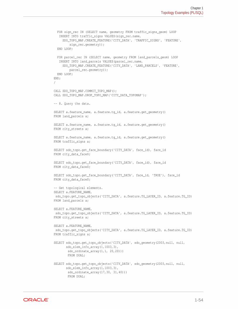
FOR sign_rec IN (SELECT name, geometry FROM traffic_signs_geom) LOOP INSERT INTO traffic_signs VALUES(sign_rec.name, SDO_TOPO_MAP.CREATE_FEATURE('CITY_DATA', 'TRAFFIC_SIGNS', 'FEATURE', sign_rec.geometry)); END LOOP; FOR parcel_rec IN (SELECT name, geometry FROM land_parcels_geom) LOOP INSERT INTO land_parcels VALUES(parcel_rec.name, SDO_TOPO_MAP.CREATE_FEATURE('CITY_DATA', 'LAND_PARCELS', 'FEATURE', parcel_rec.geometry)); END LOOP;END;/ CALL SDO_TOPO_MAP.COMMIT_TOPO_MAP();CALL SDO_TOPO_MAP.DROP_TOPO_MAP('CITY_DATA_TOPOMAP'); -- 8. Query the data. SELECT a.feature_name, a.feature.tg_id, a.feature.get_geometry()FROM land_parcels a; SELECT a.feature_name, a.feature.tg_id, a.feature.get_geometry()FROM city_streets a; SELECT a.feature_name, a.feature.tg_id, a.feature.get_geometry()FROM traffic_signs a; SELECT sdo_topo.get_face_boundary('CITY_DATA', face_id), face_idFROM city_data_face$; SELECT sdo_topo.get_face_boundary('CITY_DATA', face_id), face_idFROM city_data_face$; SELECT sdo_topo.get_face_boundary('CITY_DATA', face_id, 'TRUE'), face_idFROM city_data_face$; -- Get topological elements.SELECT a.FEATURE_NAME, sdo_topo.get_topo_objects('CITY_DATA', a.feature.TG_LAYER_ID, a.feature.TG_ID)FROM land_parcels a; SELECT a.FEATURE_NAME, sdo_topo.get_topo_objects('CITY_DATA', a.feature.TG_LAYER_ID, a.feature.TG_ID)FROM city_streets a; SELECT a.FEATURE_NAME, sdo_topo.get_topo_objects('CITY_DATA', a.feature.TG_LAYER_ID, a.feature.TG_ID)FROM traffic_signs a; SELECT sdo_topo.get_topo_objects('CITY_DATA', sdo_geometry(2003,null, null, sdo_elem_info_array(1,1003,3), sdo_ordinate_array(1,1, 20,20))) FROM DUAL; SELECT sdo_topo.get_topo_objects('CITY_DATA', sdo_geometry(2003,null, null, sdo_elem_info_array(1,1003,3), sdo_ordinate_array(17,30, 31,40))) FROM DUAL;
Chapter 1Topology Examples (PL/SQL)
1-54
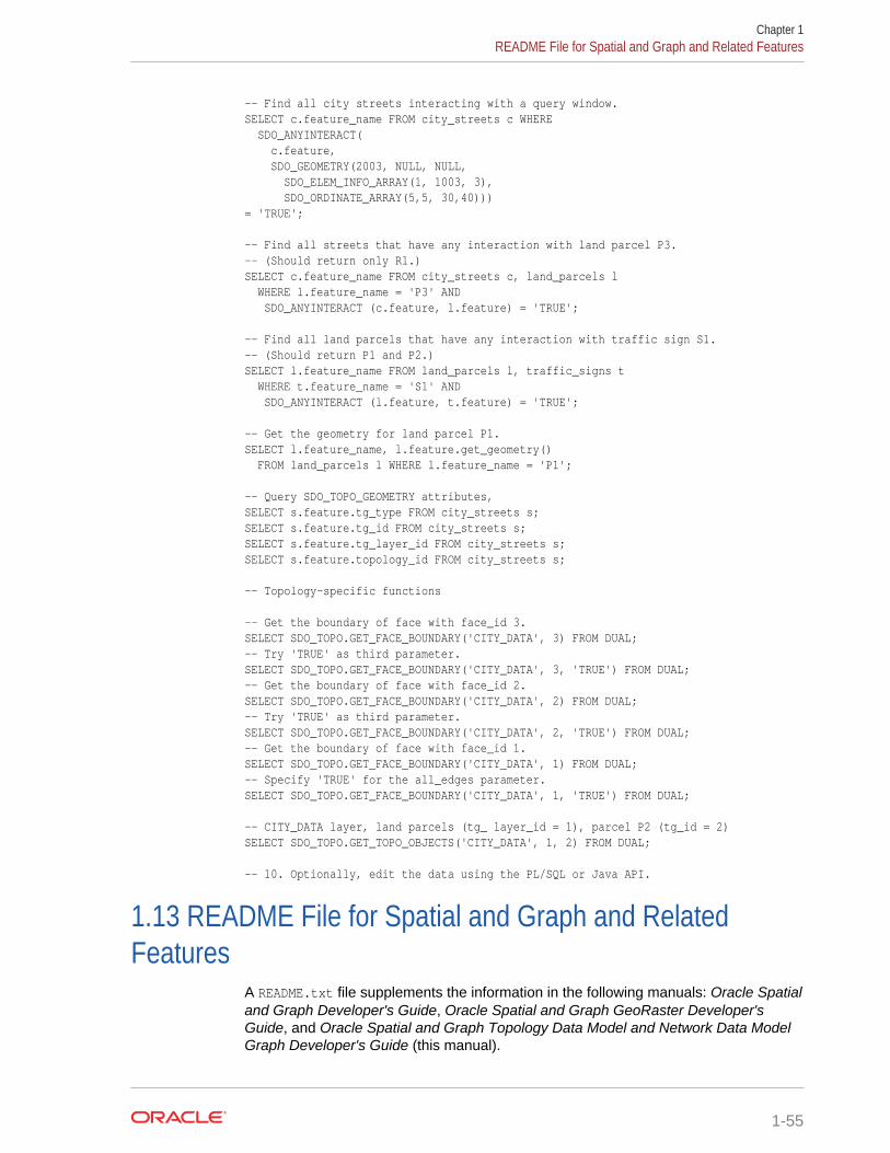
-- Find all city streets interacting with a query window.SELECT c.feature_name FROM city_streets c WHERE SDO_ANYINTERACT( c.feature, SDO_GEOMETRY(2003, NULL, NULL, SDO_ELEM_INFO_ARRAY(1, 1003, 3), SDO_ORDINATE_ARRAY(5,5, 30,40)))= 'TRUE'; -- Find all streets that have any interaction with land parcel P3.-- (Should return only R1.)SELECT c.feature_name FROM city_streets c, land_parcels l WHERE l.feature_name = 'P3' AND SDO_ANYINTERACT (c.feature, l.feature) = 'TRUE'; -- Find all land parcels that have any interaction with traffic sign S1.-- (Should return P1 and P2.)SELECT l.feature_name FROM land_parcels l, traffic_signs t WHERE t.feature_name = 'S1' AND SDO_ANYINTERACT (l.feature, t.feature) = 'TRUE'; -- Get the geometry for land parcel P1.SELECT l.feature_name, l.feature.get_geometry() FROM land_parcels l WHERE l.feature_name = 'P1'; -- Query SDO_TOPO_GEOMETRY attributes,SELECT s.feature.tg_type FROM city_streets s;SELECT s.feature.tg_id FROM city_streets s;SELECT s.feature.tg_layer_id FROM city_streets s;SELECT s.feature.topology_id FROM city_streets s; -- Topology-specific functions -- Get the boundary of face with face_id 3.SELECT SDO_TOPO.GET_FACE_BOUNDARY('CITY_DATA', 3) FROM DUAL;-- Try 'TRUE' as third parameter.SELECT SDO_TOPO.GET_FACE_BOUNDARY('CITY_DATA', 3, 'TRUE') FROM DUAL;-- Get the boundary of face with face_id 2.SELECT SDO_TOPO.GET_FACE_BOUNDARY('CITY_DATA', 2) FROM DUAL;-- Try 'TRUE' as third parameter.SELECT SDO_TOPO.GET_FACE_BOUNDARY('CITY_DATA', 2, 'TRUE') FROM DUAL;-- Get the boundary of face with face_id 1.SELECT SDO_TOPO.GET_FACE_BOUNDARY('CITY_DATA', 1) FROM DUAL;-- Specify 'TRUE' for the all_edges parameter.SELECT SDO_TOPO.GET_FACE_BOUNDARY('CITY_DATA', 1, 'TRUE') FROM DUAL; -- CITY_DATA layer, land parcels (tg_ layer_id = 1), parcel P2 (tg_id = 2)SELECT SDO_TOPO.GET_TOPO_OBJECTS('CITY_DATA', 1, 2) FROM DUAL; -- 10. Optionally, edit the data using the PL/SQL or Java API.
1.13 README File for Spatial and Graph and RelatedFeatures
A README.txt file supplements the information in the following manuals: Oracle Spatialand Graph Developer's Guide, Oracle Spatial and Graph GeoRaster Developer'sGuide, and Oracle Spatial and Graph Topology Data Model and Network Data ModelGraph Developer's Guide (this manual).
Chapter 1README File for Spatial and Graph and Related Features
1-55

This file is located at:
$ORACLE_HOME/md/doc/README.txt
Chapter 1README File for Spatial and Graph and Related Features
1-56
2Editing Topologies
Node and edge data in a topology can be edited. The operations include adding,moving, and removing nodes and edges, and updating the coordinates of an edge.
This chapter explains two approaches to editing topology data, and it explains why oneapproach (creating and using a special cache) is better in most cases. It alsodescribes the behavior and implications of some major types of editing operations.
The explanations in this chapter refer mainly to the PL/SQL application programminginterface (API) provided in the MDSYS.SDO_TOPO_MAP package, which isdocumented in SDO_TOPO_MAP Package Subprograms. However, you can alsoperform topology editing operations using the client-side Java API, which is introducedin Topology Data Model Java Interface and is explained in the Javadoc-generateddocumentation.
To edit topology data, always use the PL/SQL or Java API. Do not try to performediting operations by directly modifying the node, edge, or face information tables.
• Approaches for Editing Topology Data
• Performing Operations on NodesThis topic contains sections that describe the effects of adding, moving, andremoving nodes, and that explain how to perform these operations using thePL/SQL API.
• Performing Operations on EdgesThis topic describes the effects of adding, moving, removing, and updating edges,and explains how to perform these operations using the PL/SQL API.
See Also:
• Cross-Schema Topology Editing
2.1 Approaches for Editing Topology DataWhenever you need to edit a topology, you can use PL/SQL or Java API. In bothcases, Oracle Spatial and Graph uses an in-memory topology cache, specifically, aTopoMap object. (This object is described in TopoMap Objects.)
• If you use the PL/SQL API, you can either explicitly create and use the cache orallow Spatial and Graph to create and use the cache automatically.
• If you use the Java API, you must explicitly create and use the cache.
Allowing Spatial and Graph to create and manage the cache automatically is simpler,because it involves fewer steps than creating and using a cache. However, becauseallowing Spatial and Graph to create and manage the cache involves more database
2-1

activity and disk accesses, it is less efficient when you need to edit more than a fewtopological elements.
• TopoMap Objects
• Specifying the Editing Approach with the Topology Parameter
• Using GET_xxx Topology Functions
• Process for Editing Using Cache Explicitly (PL/SQL API)
• Process for Editing Using the Java API
• Error Handling for Topology Editing
2.1.1 TopoMap ObjectsA TopoMap object is associated with an in-memory cache that is associated with atopology. If you explicitly create and use a cache for editing a topology, you mustcreate a TopoMap object to be associated with a topology, load all or some of thetopology into the cache, edit objects, periodically update the topology to write changesto the database, commit the changes made in the cache, and clear the cache.
Although this approach involves more steps than allowing Spatial and Graph to createand use the cache automatically, it is much faster and more efficient for most topologyediting sessions, which typically affect hundreds or thousands of topological elements.It is the approach shown in most explanations and illustrations.
A TopoMap object can be updatable or read-only, depending on the value of theallow_updates parameter when you call the SDO_TOPO_MAP.LOAD_TOPO_MAPfunction or procedure:
• With a read-only TopoMap object, topological elements (primitives) are loaded butnot locked.
• With an updatable TopoMap object, topological elements (primitives) are loadedand locked. If you specified a rectangular window for an updatable TopoMapobject, you can edit only those topological elements inside the specified window.(The TopoMap object may also contain locked topological elements that youcannot edit directly, but that Oracle Spatial and Graph can modify indirectly asneeded.)
For more information about what occurs when you use an updatable TopoMapobject, see the Usage Notes for the SDO_TOPO_MAP.LOAD_TOPO_MAPfunction or procedure.
The following procedures set an updatable TopoMap object to be read-only:
• SDO_TOPO_MAP.COMMIT_TOPO_MAP
• SDO_TOPO_MAP.ROLLBACK_TOPO_MAP
• SDO_TOPO_MAP.CLEAR_TOPO_MAP
Within a user session at any given time, there can be no more than one updatableTopoMap object. However, multiple different user sessions can work with updatableTopoMap objects based on the same topology, as long as their editing windows do notcontain any topological elements that are in any other updatable TopoMap objects.There can be multiple read-only TopoMap objects within and across user sessions.
Chapter 2Approaches for Editing Topology Data
2-2
Two or more users can edit a topology at the same time as long as their editingwindows (specified in the call to the SDO_TOPO_MAP.LOAD_TOPO_MAP function orprocedure) do not overlap.
2.1.2 Specifying the Editing Approach with the Topology ParameterFor many SDO_TOPO_MAP package functions and procedures that edit topologies,such as SDO_TOPO_MAP.ADD_NODE or SDO_TOPO_MAP.MOVE_EDGE, youindicate the approach you are using for editing by specifying either a topology name ora null value for the first parameter, which is named topology:
• If you specify a topology name, Spatial and Graph checks to see if an updatableTopoMap object already exists in the user session; and if one does not exist,Spatial and Graph creates an internal TopoMap object, uses that cache to performthe editing operation, commits the change (or rolls back changes to the savepointat the beginning of the process if an exception occurred), and deletes theTopoMap object. (If an updatable TopoMap object already exists, an exception israised.) For example, the following statement removes the node with node IDvalue 99 from the MY_TOPO topology:
CALL SDO_TOPO_MAP.REMOVE_NODE('MY_TOPO', 99);
• If you specify a null value, Spatial and Graph checks to see if an updatableTopoMap object already exists in the user session; and if one does exist, Spatialand Graph performs the operation in the TopoMap object's cache. (If no updatableTopoMap object exists, an exception is raised.) For example, the followingstatement removes the node with node ID value 99 from the current updatableTopoMap object:
CALL SDO_TOPO_MAP.REMOVE_NODE(null, 99);
2.1.3 Using GET_xxx Topology FunctionsSome SDO_TOPO_MAP package functions that get information about topologieshave topology and topo_map as their first two parameters. Examples of such functionsare SDO_TOPO_MAP.GET_EDGE_COORDS and SDO_TOPO_MAP.GET_NODE_STAR. To use these functions, specify a valid valuefor one parameter and a null value for the other parameter, as follows:
• If you specify a valid topology parameter value, Spatial and Graph retrieves theinformation for the specified topology. It creates an internal TopoMap object, usesthat cache to perform the operation, and deletes the TopoMap object. Forexample, the following statement returns the edge coordinates of the edge with anID value of 1 from the CITY_DATA topology:
SELECT SDO_TOPO_MAP.GET_EDGE_COORDS('CITY_DATA', null, 1) FROM DUAL;
• If you specify a null topology parameter value and a valid topo_map parametervalue, Spatial and Graph uses the specified TopoMap object (which can beupdatable or read-only) to retrieve the information for the specified topology. Forexample, the following statement returns the edge coordinates of the edge with anID value of 1 from the CITY_DATA_TOPOMAP TopoMap object:
SELECT SDO_TOPO_MAP.GET_EDGE_COORDS(null, 'CITY_DATA_TOPOMAP', 1) FROM DUAL;
• If you specify a null or invalid value for both the topology and topo_mapparameters, an exception is raised.
Chapter 2Approaches for Editing Topology Data
2-3
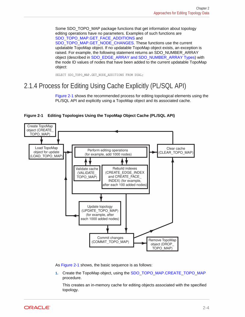
Some SDO_TOPO_MAP package functions that get information about topologyediting operations have no parameters. Examples of such functions are SDO_TOPO_MAP.GET_FACE_ADDITIONS and SDO_TOPO_MAP.GET_NODE_CHANGES. These functions use the currentupdatable TopoMap object. If no updatable TopoMap object exists, an exception israised. For example, the following statement returns an SDO_NUMBER_ARRAYobject (described in SDO_EDGE_ARRAY and SDO_NUMBER_ARRAY Types) withthe node ID values of nodes that have been added to the current updatable TopoMapobject:
SELECT SDO_TOPO_MAP.GET_NODE_ADDITIONS FROM DUAL;
2.1.4 Process for Editing Using Cache Explicitly (PL/SQL API)Figure 2-1 shows the recommended process for editing topological elements using thePL/SQL API and explicitly using a TopoMap object and its associated cache.
Figure 2-1 Editing Topologies Using the TopoMap Object Cache (PL/SQL API)
Load TopoMap object for update
(LOAD_TOPO_MAP)
Update topology (UPDATE_TOPO_MAP)
(for example, after each 1000 added nodes)
Commit changes (COMMIT_TOPO_MAP)
Perform editing operations (for example, add 1000 nodes)
Create TopoMap object (CREATE_
TOPO_MAP)
Remove TopoMap object (DROP_ TOPO_MAP)
Rebuild indexes (CREATE_EDGE_INDEX
and CREATE_FACE_ INDEX) (for example,
after each 100 added nodes)
Clear cache (CLEAR_TOPO_MAP)
Validate cache (VALIDATE_ TOPO_MAP)
As Figure 2-1 shows, the basic sequence is as follows:
1. Create the TopoMap object, using the SDO_TOPO_MAP.CREATE_TOPO_MAPprocedure.
This creates an in-memory cache for editing objects associated with the specifiedtopology.
Chapter 2Approaches for Editing Topology Data
2-4
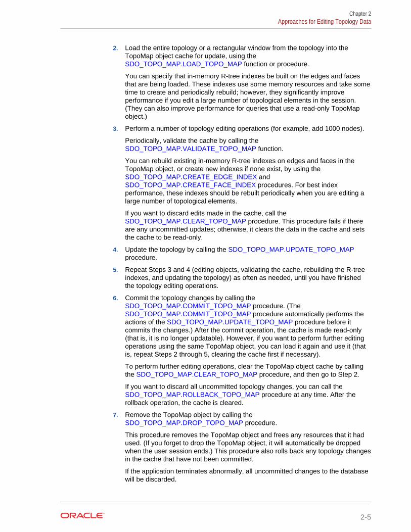
2. Load the entire topology or a rectangular window from the topology into theTopoMap object cache for update, using the SDO_TOPO_MAP.LOAD_TOPO_MAP function or procedure.
You can specify that in-memory R-tree indexes be built on the edges and facesthat are being loaded. These indexes use some memory resources and take sometime to create and periodically rebuild; however, they significantly improveperformance if you edit a large number of topological elements in the session.(They can also improve performance for queries that use a read-only TopoMapobject.)
3. Perform a number of topology editing operations (for example, add 1000 nodes).
Periodically, validate the cache by calling the SDO_TOPO_MAP.VALIDATE_TOPO_MAP function.
You can rebuild existing in-memory R-tree indexes on edges and faces in theTopoMap object, or create new indexes if none exist, by using the SDO_TOPO_MAP.CREATE_EDGE_INDEX and SDO_TOPO_MAP.CREATE_FACE_INDEX procedures. For best indexperformance, these indexes should be rebuilt periodically when you are editing alarge number of topological elements.
If you want to discard edits made in the cache, call the SDO_TOPO_MAP.CLEAR_TOPO_MAP procedure. This procedure fails if thereare any uncommitted updates; otherwise, it clears the data in the cache and setsthe cache to be read-only.
4. Update the topology by calling the SDO_TOPO_MAP.UPDATE_TOPO_MAPprocedure.
5. Repeat Steps 3 and 4 (editing objects, validating the cache, rebuilding the R-treeindexes, and updating the topology) as often as needed, until you have finishedthe topology editing operations.
6. Commit the topology changes by calling the SDO_TOPO_MAP.COMMIT_TOPO_MAP procedure. (The SDO_TOPO_MAP.COMMIT_TOPO_MAP procedure automatically performs theactions of the SDO_TOPO_MAP.UPDATE_TOPO_MAP procedure before itcommits the changes.) After the commit operation, the cache is made read-only(that is, it is no longer updatable). However, if you want to perform further editingoperations using the same TopoMap object, you can load it again and use it (thatis, repeat Steps 2 through 5, clearing the cache first if necessary).
To perform further editing operations, clear the TopoMap object cache by callingthe SDO_TOPO_MAP.CLEAR_TOPO_MAP procedure, and then go to Step 2.
If you want to discard all uncommitted topology changes, you can call the SDO_TOPO_MAP.ROLLBACK_TOPO_MAP procedure at any time. After therollback operation, the cache is cleared.
7. Remove the TopoMap object by calling the SDO_TOPO_MAP.DROP_TOPO_MAP procedure.
This procedure removes the TopoMap object and frees any resources that it hadused. (If you forget to drop the TopoMap object, it will automatically be droppedwhen the user session ends.) This procedure also rolls back any topology changesin the cache that have not been committed.
If the application terminates abnormally, all uncommitted changes to the databasewill be discarded.
Chapter 2Approaches for Editing Topology Data
2-5
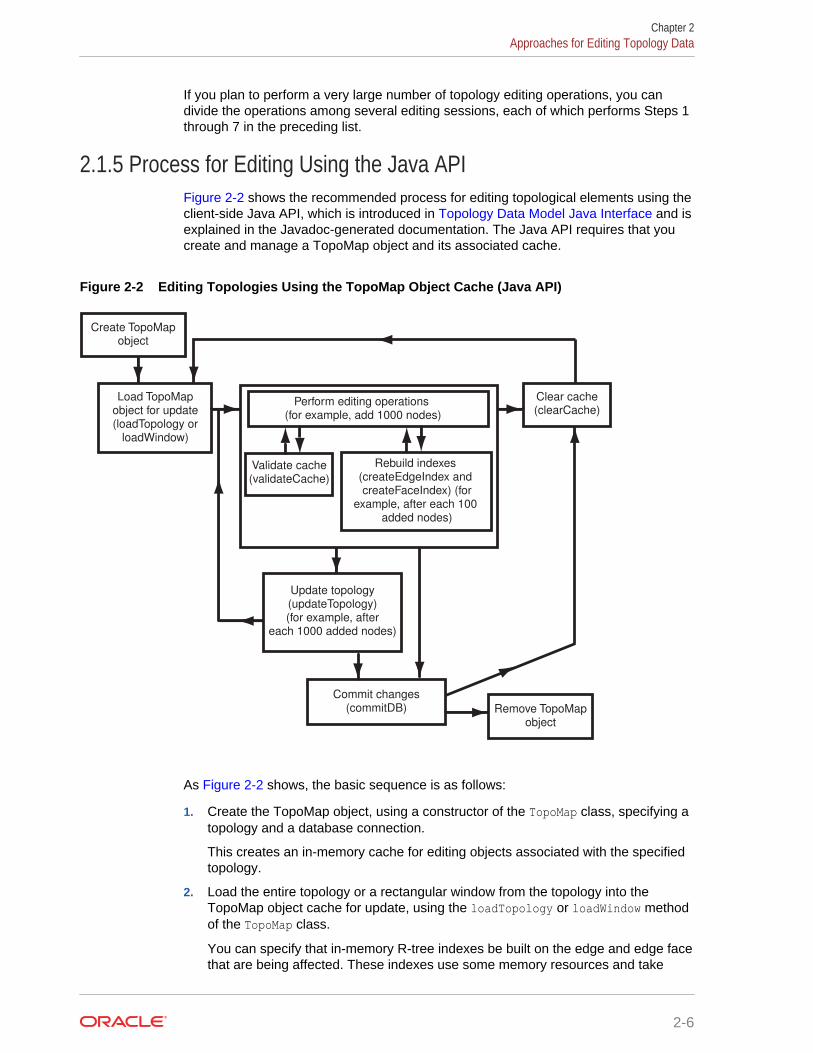
If you plan to perform a very large number of topology editing operations, you candivide the operations among several editing sessions, each of which performs Steps 1through 7 in the preceding list.
2.1.5 Process for Editing Using the Java APIFigure 2-2 shows the recommended process for editing topological elements using theclient-side Java API, which is introduced in Topology Data Model Java Interface and isexplained in the Javadoc-generated documentation. The Java API requires that youcreate and manage a TopoMap object and its associated cache.
Figure 2-2 Editing Topologies Using the TopoMap Object Cache (Java API)
Load TopoMap object for update (loadTopology or
loadWindow)
Update topology (updateTopology) (for example, after
each 1000 added nodes)
Commit changes (commitDB)
Perform editing operations (for example, add 1000 nodes)
Create TopoMap object
Remove TopoMap object
Rebuild indexes (createEdgeIndex and createFaceIndex) (for
example, after each 100 added nodes)
Clear cache (clearCache)
Validate cache (validateCache)
As Figure 2-2 shows, the basic sequence is as follows:
1. Create the TopoMap object, using a constructor of the TopoMap class, specifying atopology and a database connection.
This creates an in-memory cache for editing objects associated with the specifiedtopology.
2. Load the entire topology or a rectangular window from the topology into theTopoMap object cache for update, using the loadTopology or loadWindow methodof the TopoMap class.
You can specify that in-memory R-tree indexes be built on the edge and edge facethat are being affected. These indexes use some memory resources and take
Chapter 2Approaches for Editing Topology Data
2-6

some time to create and periodically rebuild; however, they significantly improveperformance if you edit a large number of topological elements during thedatabase connection.
3. Perform a number of topology editing operations (for example, add 1000 nodes),and update the topology by calling the updateTopology method of the TopoMapclass.
Periodically, validate the cache by calling the validateCache method of theTopoMap class.
If you caused in-memory R-tree indexes to be created when you loaded theTopoMap object (in Step 2), you can periodically (for example, after each additionof 100 nodes) rebuild the indexes by calling the createEdgeIndex andcreateFaceIndex methods of the TopoMap class. For best index performance,these indexes should be rebuilt periodically when you are editing a large numberof topological elements.
If you do not want to update the topology but instead want to discard edits made inthe cache since the last update, call the clearCache method of the TopoMap class.The clearCache method fails if there are any uncommitted updates; otherwise, itclears the data in the cache and sets the cache to be read-only.
4. Update the topology by calling the updateTopology method of the TopoMap class.
5. Repeat Steps 3 and 4 (editing objects, validating the cache, rebuilding the R-treeindexes, and updating the topology) as often as needed, until you have finishedthe topology editing operations.
6. Commit the topology changes by calling the commitDB method of the TopoMapclass. (The commitDB method automatically calls the updateTopology methodbefore it commits the changes.) After the commit operation, the cache is maderead-only (that is, it is no longer updatable). However, if you want to performfurther editing operations using the same TopoMap object, you can load it againand use it (that is, repeat Steps 2 through 5, clearing the cache first if necessary).
To perform further editing operations, clear the TopoMap object cache by callingthe clearCache method of the TopoMap class, and then go to Step 2.
If you want to discard all uncommitted topology changes, you can call therollbackDB method of the TopoMap class at any time. After the rollback operation,the cache is cleared.
7. Remove the TopoMap object by setting the TopoMap object to null, which makesthe object available for garbage collection and frees any resources that it hadused. (If you forget to remove the TopoMap object, it will automatically be garbagecollected when the application ends.)
If the application terminates abnormally, all uncommitted changes to the databasewill be discarded.
If you plan to perform a very large number of topology editing operations, you candivide the operations among several editing sessions, each of which performs Steps 1through 7 in the preceding list.
2.1.6 Error Handling for Topology EditingThis section discusses the following conditions.
• Input Parameter Errors
Chapter 2Approaches for Editing Topology Data
2-7

• All Exceptions
2.1.6.1 Input Parameter ErrorsWhen an SDO_TOPO_MAP PL/SQL subprogram or a public method in the TopoMapJava class is called, it validates the values of the input parameters, and it uses orcreates a TopoMap object to perform the editing or read-only operation. Wheneverthere is an input error, an oracle.spatial.topo.TopoDataException exception isthrown. Other errors may occur when the underlying TopoMap object performs anoperation.
If the method is called from SQL or PL/SQL, the caller gets the following errormessage:
ORA-29532: Java call terminated by uncaught Java exception:<specific error message text>
The following PL/SQL example shows how you can handle a TopoDataExceptionexception:
DECLARE topo_data_error EXCEPTION; PRAGMA EXCEPTION_INIT(topo_data_error, -29532);BEGIN sdo_topo_map.create_topo_map(null, null, 100, 100, 100);EXCEPTION WHEN topo_data_error THEN DBMS_OUTPUT.PUT_LINE(SQLERRM);END;/
The preceding example generates the following output:
ORA-29532: Java call terminated by uncaught Java exception:oracle.spatial.topo.TopoDataException: invalid TopoMap name
2.1.6.2 All ExceptionsThe following actions are performed automatically when any exception occurs in a callto any of the following SDO_TOPO_MAP PL/SQL subprograms or their associatedmethods in the TopoMap Java class: SDO_TOPO_MAP.ADD_EDGE (addEdge), SDO_TOPO_MAP.ADD_ISOLATED_NODE (addIsolatedNode), SDO_TOPO_MAP.ADD_LOOP (addLoop), SDO_TOPO_MAP.ADD_NODE (addNode), SDO_TOPO_MAP.ADD_POINT_GEOMETRY (addPointGeometry), SDO_TOPO_MAP.ADD_POLYGON_GEOMETRY (addPolygonGeometry), SDO_TOPO_MAP.CHANGE_EDGE_COORDS (changeEdgeCoords), SDO_TOPO_MAP.MOVE_ISOLATED_NODE (moveIsolatedNode), SDO_TOPO_MAP.MOVE_NODE (moveNode), SDO_TOPO_MAP.MOVE_EDGE(moveEdge), SDO_TOPO_MAP.REMOVE_EDGE (removeEdge), SDO_TOPO_MAP.REMOVE_NODE (removeNode), and SDO_TOPO_MAP.UPDATE_TOPO_MAP (updateTopology).
• The transaction is rolled back.
• The TopoMap object cache is cleared.
• The TopoMap object is made read-only.
Chapter 2Approaches for Editing Topology Data
2-8
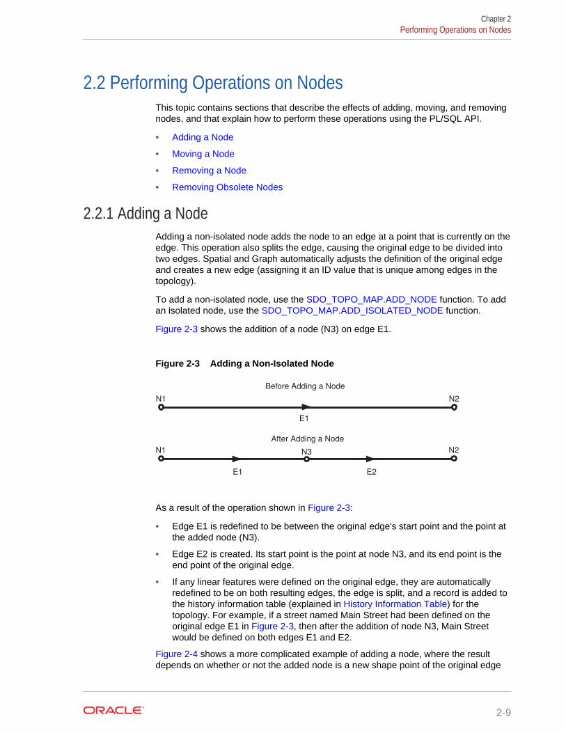
2.2 Performing Operations on NodesThis topic contains sections that describe the effects of adding, moving, and removingnodes, and that explain how to perform these operations using the PL/SQL API.
• Adding a Node
• Moving a Node
• Removing a Node
• Removing Obsolete Nodes
2.2.1 Adding a NodeAdding a non-isolated node adds the node to an edge at a point that is currently on theedge. This operation also splits the edge, causing the original edge to be divided intotwo edges. Spatial and Graph automatically adjusts the definition of the original edgeand creates a new edge (assigning it an ID value that is unique among edges in thetopology).
To add a non-isolated node, use the SDO_TOPO_MAP.ADD_NODE function. To addan isolated node, use the SDO_TOPO_MAP.ADD_ISOLATED_NODE function.
Figure 2-3 shows the addition of a node (N3) on edge E1.
Figure 2-3 Adding a Non-Isolated Node
N1 N2
Before Adding a Node
E1
N1 N2
After Adding a Node
E1
N3
E2
As a result of the operation shown in Figure 2-3:
• Edge E1 is redefined to be between the original edge's start point and the point atthe added node (N3).
• Edge E2 is created. Its start point is the point at node N3, and its end point is theend point of the original edge.
• If any linear features were defined on the original edge, they are automaticallyredefined to be on both resulting edges, the edge is split, and a record is added tothe history information table (explained in History Information Table) for thetopology. For example, if a street named Main Street had been defined on theoriginal edge E1 in Figure 2-3, then after the addition of node N3, Main Streetwould be defined on both edges E1 and E2.
Figure 2-4 shows a more complicated example of adding a node, where the resultdepends on whether or not the added node is a new shape point of the original edge
Chapter 2Performing Operations on Nodes
2-9

(that is, on the value of the is_new_shape_point parameter to the SDO_TOPO_MAP.ADD_NODE function).
Figure 2-4 Effect of is_new_shape_point Value on Adding a Node
N3
E2
Original Edge with Shape Points
New Node Is Not a Shape Point of the Original Edge
New Node Is a Shape Point of the Original Edge
N1 N2
N1 N2
N3
E1
E1
E2
N1 N2
E1
In Figure 2-4:
• In the top part of the figure, the original edge (E1) starts at node N1, ends at nodeN2, and has two intermediate shape points.
• In the middle part of the figure, a new node (N3) is added that is not a shape pointof the original edge, but instead is a new shape point (that is,is_new_shape_point=>'TRUE'). The new node is added at the location specifiedwith the point parameter, and is added after the vertex specified in thecoord_index parameter (in this case, coord_index=>1 to indicate after the firstvertex). The new node becomes the end node for edge E1 and the start node forthe new edge E2, which ends at node N2.
• In the bottom part of the figure, a new node (N3) is added that is a shape point ofthe original edge, and is thus not a new shape point (that is,is_new_shape_point=>'FALSE'). Because it is not a new shape point, the node isadded at the vertex specified with the coord_index parameter (in this case,coord_index=>2). As in the middle part of the figure, the new node becomes theend node for edge E1 and the start node for the new edge E2, which ends at nodeN2.
Chapter 2Performing Operations on Nodes
2-10

2.2.2 Moving a NodeMoving a non-isolated node to a new position causes the ends of all edges that areattached to the node to move with the node. You must specify the vertices for alledges affected by the moving of the node; each point (start or end) that is attached tothe node must have the same coordinates as the new location of the node, and theother end points (not the moved node) of each affected edge must remain the same.
To move a non-isolated node, use the SDO_TOPO_MAP.MOVE_NODE procedure.To move an isolated node, use the SDO_TOPO_MAP.MOVE_ISOLATED_NODEprocedure.
Figure 2-5 shows the original topology before node N1 is moved.
Figure 2-5 Topology Before Moving a Non-Isolated Node
E1 E2E3
E4
E5E6
E7
E8
E9
F1 F2
F3
F4
F5
N1
E10
Figure 2-6 shows two cases of the original topology after node N1 is moved. In onecase, no reshaping occurs; that is, all edges affected by the movement are specifiedas straight lines. In the other case, reshaping occurs; that is, one or more affectededges are specified as line segments with multiple vertices.
Figure 2-6 Topology After Moving a Non-Isolated Node
E1 E2E3
E4
E5E6
E7
E8
E9
F1F2
F3
F4
F5
N1
E10
Without Reshaping With Reshaping
E1 E2E3
E4
E5E6
E7
E8
E9
F1 F2
F3F4
F5
N1
E10
Chapter 2Performing Operations on Nodes
2-11
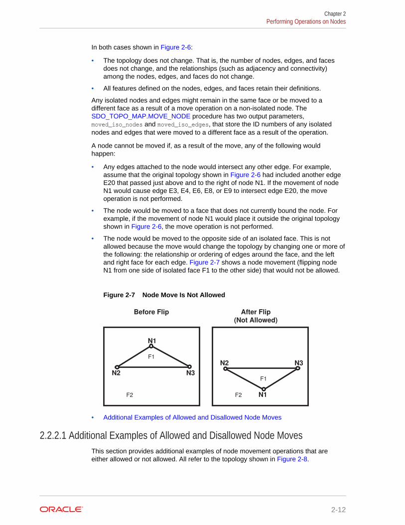
In both cases shown in Figure 2-6:
• The topology does not change. That is, the number of nodes, edges, and facesdoes not change, and the relationships (such as adjacency and connectivity)among the nodes, edges, and faces do not change.
• All features defined on the nodes, edges, and faces retain their definitions.
Any isolated nodes and edges might remain in the same face or be moved to adifferent face as a result of a move operation on a non-isolated node. The SDO_TOPO_MAP.MOVE_NODE procedure has two output parameters,moved_iso_nodes and moved_iso_edges, that store the ID numbers of any isolatednodes and edges that were moved to a different face as a result of the operation.
A node cannot be moved if, as a result of the move, any of the following wouldhappen:
• Any edges attached to the node would intersect any other edge. For example,assume that the original topology shown in Figure 2-6 had included another edgeE20 that passed just above and to the right of node N1. If the movement of nodeN1 would cause edge E3, E4, E6, E8, or E9 to intersect edge E20, the moveoperation is not performed.
• The node would be moved to a face that does not currently bound the node. Forexample, if the movement of node N1 would place it outside the original topologyshown in Figure 2-6, the move operation is not performed.
• The node would be moved to the opposite side of an isolated face. This is notallowed because the move would change the topology by changing one or more ofthe following: the relationship or ordering of edges around the face, and the leftand right face for each edge. Figure 2-7 shows a node movement (flipping nodeN1 from one side of isolated face F1 to the other side) that would not be allowed.
Figure 2-7 Node Move Is Not Allowed
Before Flip After Flip
(Not Allowed)
F1
F2
N2 N3
N1
F1
F2
N3N2
N1
• Additional Examples of Allowed and Disallowed Node Moves
2.2.2.1 Additional Examples of Allowed and Disallowed Node MovesThis section provides additional examples of node movement operations that areeither allowed or not allowed. All refer to the topology shown in Figure 2-8.
Chapter 2Performing Operations on Nodes
2-12

Figure 2-8 Topology for Node Movement Examples
E1E2
E3
E4
E5
F1
F2
P1 P2
P3
N1
N2
P4
In the topology shown in Figure 2-8:
• Attempts will be made to move node N1 to points P1, P2, P3, and P4. (Thesepoints are locations but are not existing nodes.)
• The edges have no shape points, either before or after the move operation.
• New vertices are specified for the edges E1, E2, E3, and E4, but the ID values ofthe start and end points for the edges remain the same.
When the following node move operations are attempted using the topology shown in Figure 2-8, the following results occur:
• Moving node N1 to point P1: Not allowed, because one or more of the fourattached edges would intersect edge E5. (Edge E3 would definitely intersect edgeE5 if the move were allowed.)
• Moving node N1 to point P2: Allowed.
• Moving node N1 to point P3: Allowed. However, this operation causes the isolatednode N2 to change from face F2 to face F1, and this might cause the applicationto want to roll back or disallow the movement of node N1. Similarly, if themovement of a node would cause any isolated edges or faces to change from oneface to another, the application might want to roll back or disallow the node moveoperation.
• Moving node N1 to point P4: Not allowed, because the node must be moved to apoint in a face that bounds the original (current) position of the node.
2.2.3 Removing a NodeYou can remove individual nodes (isolated or non-isolated), as explained in thissection, and you can remove all obsolete nodes in a topology, as explained in Removing Obsolete Nodes.
Removing a non-isolated node deletes the node and merges the edges that wereattached to the node into a single edge. (Spatial and Graph applies complex rules,which are not documented, to determine the ID value and direction of the resultingedge.)
Chapter 2Performing Operations on Nodes
2-13
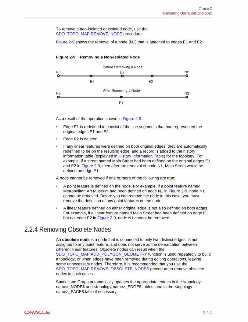
To remove a non-isolated or isolated node, use the SDO_TOPO_MAP.REMOVE_NODE procedure.
Figure 2-9 shows the removal of a node (N1) that is attached to edges E1 and E2.
Figure 2-9 Removing a Non-Isolated Node
N3 N2After Removing a Node
E1
N3 N2
Before Removing a Node
E1
N1
E2
As a result of the operation shown in Figure 2-9:
• Edge E1 is redefined to consist of the line segments that had represented theoriginal edges E1 and E2.
• Edge E2 is deleted.
• If any linear features were defined on both original edges, they are automaticallyredefined to be on the resulting edge, and a record is added to the historyinformation table (explained in History Information Table) for the topology. Forexample, if a street named Main Street had been defined on the original edges E1and E2 in Figure 2-9, then after the removal of node N1, Main Street would bedefined on edge E1.
A node cannot be removed if one or more of the following are true:
• A point feature is defined on the node. For example, if a point feature namedMetropolitan Art Museum had been defined on node N1 in Figure 2-9, node N1cannot be removed. Before you can remove the node in this case, you mustremove the definition of any point features on the node.
• A linear feature defined on either original edge is not also defined on both edges.For example, if a linear feature named Main Street had been defined on edge E1but not edge E2 in Figure 2-9, node N1 cannot be removed.
2.2.4 Removing Obsolete NodesAn obsolete node is a node that is connected to only two distinct edges, is notassigned to any point feature, and does not serve as the demarcation betweendifferent linear features. Obsolete nodes can result when the SDO_TOPO_MAP.ADD_POLYGON_GEOMETRY function is used repeatedly to builda topology, or when edges have been removed during editing operations, leavingsome unnecessary nodes. Therefore, it is recommended that you use the SDO_TOPO_MAP.REMOVE_OBSOLETE_NODES procedure to remove obsoletenodes in such cases.
Spatial and Graph automatically updates the appropriate entries in the <topology-name>_NODE$ and <topology-name>_EDGE$ tables, and in the <topology-name>_FACE$ table if necessary.
Chapter 2Performing Operations on Nodes
2-14
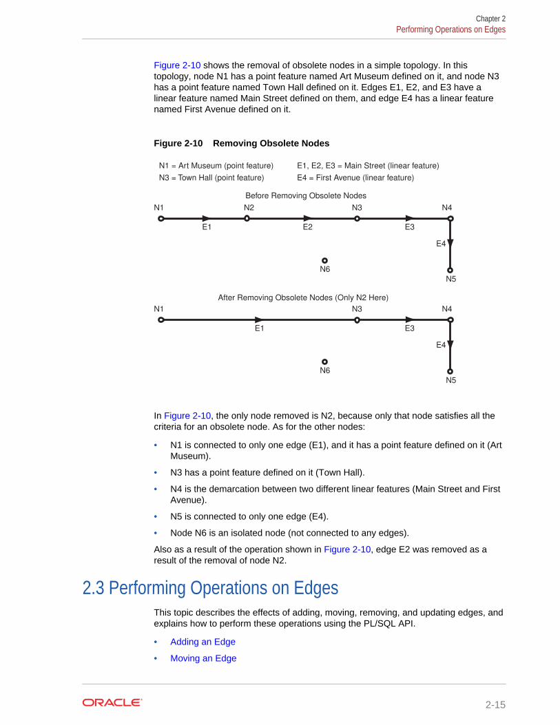
Figure 2-10 shows the removal of obsolete nodes in a simple topology. In thistopology, node N1 has a point feature named Art Museum defined on it, and node N3has a point feature named Town Hall defined on it. Edges E1, E2, and E3 have alinear feature named Main Street defined on them, and edge E4 has a linear featurenamed First Avenue defined on it.
Figure 2-10 Removing Obsolete Nodes
After Removing Obsolete Nodes (Only N2 Here)
N3N2
Before Removing Obsolete Nodes
E1
N1
E2
N4
N5
N6
E3
E4
N1 = Art Museum (point feature)
N3 = Town Hall (point feature)
E1, E2, E3 = Main Street (linear feature)
E4 = First Avenue (linear feature)
N3
E1
N1 N4
N5
N6
E3
E4
In Figure 2-10, the only node removed is N2, because only that node satisfies all thecriteria for an obsolete node. As for the other nodes:
• N1 is connected to only one edge (E1), and it has a point feature defined on it (ArtMuseum).
• N3 has a point feature defined on it (Town Hall).
• N4 is the demarcation between two different linear features (Main Street and FirstAvenue).
• N5 is connected to only one edge (E4).
• Node N6 is an isolated node (not connected to any edges).
Also as a result of the operation shown in Figure 2-10, edge E2 was removed as aresult of the removal of node N2.
2.3 Performing Operations on EdgesThis topic describes the effects of adding, moving, removing, and updating edges, andexplains how to perform these operations using the PL/SQL API.
• Adding an Edge
• Moving an Edge
Chapter 2Performing Operations on Edges
2-15
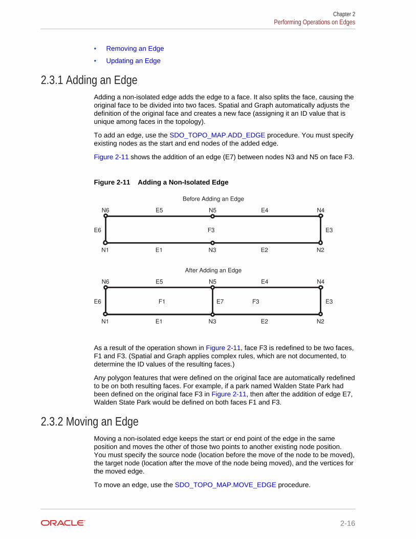
• Removing an Edge
• Updating an Edge
2.3.1 Adding an EdgeAdding a non-isolated edge adds the edge to a face. It also splits the face, causing theoriginal face to be divided into two faces. Spatial and Graph automatically adjusts thedefinition of the original face and creates a new face (assigning it an ID value that isunique among faces in the topology).
To add an edge, use the SDO_TOPO_MAP.ADD_EDGE procedure. You must specifyexisting nodes as the start and end nodes of the added edge.
Figure 2-11 shows the addition of an edge (E7) between nodes N3 and N5 on face F3.
Figure 2-11 Adding a Non-Isolated Edge
N6 N4
Before Adding an Edge
E5 N5 E4
N1 N2E1 N3 E2
E3E6 F3
N6 N4
After Adding an Edge
E5 N5 E4
N1 N2E1 N3 E2
E3E6 F1 F3E7
As a result of the operation shown in Figure 2-11, face F3 is redefined to be two faces,F1 and F3. (Spatial and Graph applies complex rules, which are not documented, todetermine the ID values of the resulting faces.)
Any polygon features that were defined on the original face are automatically redefinedto be on both resulting faces. For example, if a park named Walden State Park hadbeen defined on the original face F3 in Figure 2-11, then after the addition of edge E7,Walden State Park would be defined on both faces F1 and F3.
2.3.2 Moving an EdgeMoving a non-isolated edge keeps the start or end point of the edge in the sameposition and moves the other of those two points to another existing node position.You must specify the source node (location before the move of the node to be moved),the target node (location after the move of the node being moved), and the vertices forthe moved edge.
To move an edge, use the SDO_TOPO_MAP.MOVE_EDGE procedure.
Chapter 2Performing Operations on Edges
2-16

Figure 2-12 shows the movement of edge E7, which was originally between nodes N3and N5, to be between nodes N2 and N5.
Figure 2-12 Moving a Non-Isolated Edge
N6 N4
Before Moving an Edge
E5 N5 E4
N1 N2E1 N3 E2
E3E6 F1
N6 N4
After Moving an Edge
E5 N5 E4
N1 N2E1 N3 E2
E3E6 F1 F3E7
F3E7
As a result of the operation shown in Figure 2-12, faces F1 and F3 are automaticallyredefined to reflect the coordinates of their edges, including the new coordinates foredge E7.
Any isolated nodes and edges might remain in the same face or be moved to adifferent face as a result of a move operation on a non-isolated edge. The SDO_TOPO_MAP.MOVE_EDGE procedure has two output parameters,moved_iso_nodes and moved_iso_edges, that store the ID numbers of any isolatednodes and edges that were moved to a different face as a result of the operation.
An edge cannot be moved if, as a result of the move, any of the following wouldhappen:
• The moved edge would intersect any other edge. For example, assume that thetopology before the move, as shown in Figure 2-12, had included another edge(E10) that was between nodes N3 and N4. In this case, the movement of edge E7would cause it to intersect edge E10, and therefore the move operation is notperformed.
• The node would be moved to a face that does not currently bound the edge. Forexample, if the movement of edge E7 would place its terminating point at a nodeoutside the faces shown in Figure 2-12 (F1 and F3), the move operation is notperformed.
2.3.3 Removing an EdgeRemoving a non-isolated edge deletes the edge and merges the faces that boundedthe edge. (Spatial and Graph applies complex rules, which are not documented, todetermine the ID value of the resulting face.)
To remove an edge, use the SDO_TOPO_MAP.REMOVE_EDGE procedure.
Figure 2-13 shows the removal of an edge (E7) that is bounded by faces F1 and F3.
Chapter 2Performing Operations on Edges
2-17
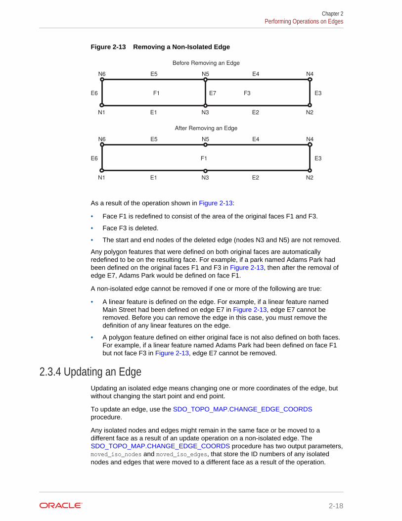
Figure 2-13 Removing a Non-Isolated Edge
N6 N4
After Removing an Edge
E5 N5 E4
N1 N2E1 N3 E2
E3E6 F1
N6 N4
Before Removing an Edge
E5 N5 E4
N1 N2E1 N3 E2
E3E6 F1 F3E7
As a result of the operation shown in Figure 2-13:
• Face F1 is redefined to consist of the area of the original faces F1 and F3.
• Face F3 is deleted.
• The start and end nodes of the deleted edge (nodes N3 and N5) are not removed.
Any polygon features that were defined on both original faces are automaticallyredefined to be on the resulting face. For example, if a park named Adams Park hadbeen defined on the original faces F1 and F3 in Figure 2-13, then after the removal ofedge E7, Adams Park would be defined on face F1.
A non-isolated edge cannot be removed if one or more of the following are true:
• A linear feature is defined on the edge. For example, if a linear feature namedMain Street had been defined on edge E7 in Figure 2-13, edge E7 cannot beremoved. Before you can remove the edge in this case, you must remove thedefinition of any linear features on the edge.
• A polygon feature defined on either original face is not also defined on both faces.For example, if a linear feature named Adams Park had been defined on face F1but not face F3 in Figure 2-13, edge E7 cannot be removed.
2.3.4 Updating an EdgeUpdating an isolated edge means changing one or more coordinates of the edge, butwithout changing the start point and end point.
To update an edge, use the SDO_TOPO_MAP.CHANGE_EDGE_COORDSprocedure.
Any isolated nodes and edges might remain in the same face or be moved to adifferent face as a result of an update operation on a non-isolated edge. The SDO_TOPO_MAP.CHANGE_EDGE_COORDS procedure has two output parameters,moved_iso_nodes and moved_iso_edges, that store the ID numbers of any isolatednodes and edges that were moved to a different face as a result of the operation.
Chapter 2Performing Operations on Edges
2-18

An edge cannot be updated if, as a result of the operation, it would intersect any otheredge. See the Usage Notes for the SDO_TOPO_MAP.CHANGE_EDGE_COORDSprocedure for more information about updating an edge.
Chapter 2Performing Operations on Edges
2-19
3SDO_TOPO Package Subprograms
The MDSYS.SDO_TOPO package contains subprograms (functions and procedures)that constitute part of the PL/SQL application programming interface (API) for theSpatial and Graph Topology Data Model feature. This package mainly containssubprograms for creating and managing topologies.
To use the subprograms in this chapter, you must understand the conceptualinformation about topology in Topology Data Model Overview.
Another package, SDO_TOPO_MAP, mainly contains subprograms related to editingtopologies. Reference information for the SDO_TOPO_MAP package is in SDO_TOPO_MAP Package Subprograms.
The rest of this chapter provides reference information about the SDO_TOPOsubprograms, listed in alphabetical order.
• SDO_TOPO.ADD_TOPO_GEOMETRY_LAYER
• SDO_TOPO.CREATE_TOPOLOGY
• SDO_TOPO.DELETE_TOPO_GEOMETRY_LAYER
• SDO_TOPO.DROP_TOPOLOGY
• SDO_TOPO.GET_FACE_BOUNDARY
• SDO_TOPO.GET_TOPO_OBJECTS
• SDO_TOPO.INITIALIZE_AFTER_IMPORT
• SDO_TOPO.INITIALIZE_METADATA
• SDO_TOPO.PREPARE_FOR_EXPORT
• SDO_TOPO.RELATE
3.1 SDO_TOPO.ADD_TOPO_GEOMETRY_LAYERFormat
SDO_TOPO.ADD_TOPO_GEOMETRY_LAYER( topology IN VARCHAR2, table_name IN VARCHAR2, column_name IN VARCHAR2, topo_geometry_layer_type IN VARCHAR2, relation_table_storage IN VARCHAR2 DEFAULT NULL, child_layer_id IN NUMBER DEFAULT NULL);
Description
Adds a topology geometry layer to a topology.
3-1

Parameters
topologyTopology to which to add the topology geometry layer containing the topologygeometries in the specified column. The topology must have been created using the SDO_TOPO.CREATE_TOPOLOGY procedure.
table_nameName of the topology geometry layer table containing the column specified incolumn_name.
column_nameName of the column (of type SDO_TOPO_GEOMETRY) containing the topologygeometries in the topology geometry layer to be added to the topology.
topo_geometry_layer_typeType of topology geometry layer: POINT, LINE, CURVE, POLYGON, orCOLLECTION.
relation_table_storagePhysical storage parameters used internally to create the <topology-name>_RELATION$ table (described in Relationship Information Table). Must be avalid string for use with the CREATE TABLE statement. For example: TABLESPACEtbs_3 STORAGE (INITIAL 100K NEXT 200K). If you do not specify this parameter, thedefault physical storage values are used.
child_layer_idLayer ID number of the child topology geometry layer for this layer, if the topology hasa topology geometry layer hierarchy. (Topology geometry layer hierarchy is explainedin Topology Geometry Layer Hierarchy.) If you do not specify this parameter and if thetopology has a topology geometry layer hierarchy, the topology geometry layer isadded to the lowest level (level 0) of the hierarchy.If the topology does not have a topology geometry layer hierarchy, do not specify thisparameter when adding any of the topology geometry layers.
Usage Notes
The first call to this procedure for a given topology creates the <topology-name>_RELATION$ table, which is described in Relationship Information Table.
This procedure automatically performs a commit operation, and therefore it cannot berolled back. To delete the topology that you just created, call the SDO_TOPO.DELETE_TOPO_GEOMETRY_LAYER procedure.
The procedure creates a spatial index on the spatial features in the topologygeometries, and a B-tree index on the combination of tg_type and tg_id in thetopology geometries.
Users granted CONNECT and RESOURCE roles must also be granted the CREATEVIEW privilege to call the procedure. This is necessary because effective with OracleDatabase 10g Release 2, the CONNECT role privilege reduction feature removed thefollowing privileges from the CONNECT role: CREATE CLUSTER, CREATEDATABASE LINK, CREATE SEQUENCE, ALTER SESSION, CREATE SYNONYM,CREATE TABLE, and CREATE VIEW.
The topology geometry layer table (table_name parameter) cannot be an object table.
Chapter 3SDO_TOPO.ADD_TOPO_GEOMETRY_LAYER
3-2
An exception is raised if topology, table_name, or column_name does not exist, or iftopo_geometry_layer_type is not one of the supported values.
Examples
The following example adds a topology geometry layer to the CITY_DATA topology. Thetopology geometry layer consists of polygon geometries in the FEATURE column ofthe LAND_PARCELS table. (The example refers to definitions and data from TopologyBuilt from Topology Data.)
EXECUTE SDO_TOPO.ADD_TOPO_GEOMETRY_LAYER('CITY_DATA', 'LAND_PARCELS', 'FEATURE', 'POLYGON');
3.2 SDO_TOPO.CREATE_TOPOLOGYFormat
SDO_TOPO.CREATE_TOPOLOGY( topology IN VARCHAR2, tolerance IN NUMBER, srid IN NUMBER DEFAULT NULL, node_table_storage IN VARCHAR2 DEFAULT NULL, edge_table_storage IN VARCHAR2 DEFAULT NULL, face_table_storage IN VARCHAR2 DEFAULT NULL, history_table_storage IN VARCHAR2 DEFAULT NULL. digits_right_of_decimal IN VARCHAR2 DEFAULT 16);
Description
Creates a topology.
Parameters
topologyName of the topology to be created. Must not exceed 20 characters.
toleranceTolerance value associated with topology geometries in the topology. (Tolerance isexplained in Tolerance in the Topology Data Model.)
sridCoordinate system (spatial reference system) associated with all topology geometrylayers in the topology. The default is null: no coordinate system is associated;otherwise, it must be a value from the SRID column of the SDO_COORD_REF_SYStable (described in Oracle Spatial and Graph Developer's Guide).
node_table_storagePhysical storage parameters used internally to create the <topology-name>_NODE$table (described in Node Information Table). Must be a valid string for use with theCREATE TABLE statement. For example: TABLESPACE tbs_3 STORAGE (INITIAL100K NEXT 200K). If you do not specify this parameter, the default physical storagevalues are used.
edge_table_storagePhysical storage parameters used internally to create the <topology-name>_EDGE$table (described in Edge Information Table). Must be a valid string for use with the
Chapter 3SDO_TOPO.CREATE_TOPOLOGY
3-3

CREATE TABLE statement. For example: TABLESPACE tbs_3 STORAGE (INITIAL100K NEXT 200K). If you do not specify this parameter, the default physical storagevalues are used.
face_table_storagePhysical storage parameters used internally to create the <topology-name>_FACE$table (described in Face Information Table). Must be a valid string for use with theCREATE TABLE statement. For example: TABLESPACE tbs_3 STORAGE (INITIAL100K NEXT 200K). If you do not specify this parameter, the default physical storagevalues are used.
history_table_storagePhysical storage parameters used internally to create the <topology-name>_HISTORY$ table (described in History Information Table. Must be a validstring for use with the CREATE TABLE statement. For example: TABLESPACE tbs_3STORAGE (INITIAL 100K NEXT 200K). If you do not specify this parameter, the defaultphysical storage values are used.
digits_right_of_decimalThe number of digits permitted to the right of the decimal point in the expression ofany coordinate position when features are added to an existing topology. All incomingfeatures (those passed as arguments to the addLinearGeometry,addPolygonGeometry, or addPointGeometry method in the Java API or the equivalentPL/SQL subprograms) will be automatically snapped (truncated) to the number ofdigits right of the decimal that is specified in this parameter. The default is 16.This value should be set to match the last digit right of the decimal point that isconsidered valid based on the accuracy of the incoming data. This mechanism isprovided to improve the stability of the computational geometry during the featureinsertion process, and to minimize the creation of sliver polygons and other undesiredresults.
Usage Notes
This procedure creates the <topology-name>_EDGE$, <topology-name>_NODE$,<topology-name>_FACE$, and <topology-name>_HISTORY$ tables, which aredescribed in Topology Data Model Tables, and it creates B-tree indexes on theprimary keys of these tables. This procedure also creates the metadata for thetopology.
In the srid parameter, you can specify a geodetic coordinate system; however, allSpatial and Graph internal operations on the topology will use Cartesian (not geodetic)arithmetic operations. (Geodetic and non-geodetic coordinate systems are discussedin Oracle Spatial and Graph Developer's Guide.)
Node, edge, face, and history tables are created without partitions; however, you canalter any of these tables to make it partitioned. You can also create a partitionedspatial index on a partitioned table, as explained in Oracle Spatial and GraphDeveloper's Guide.
This procedure automatically performs a commit operation, and therefore it cannot berolled back. To delete the topology that you just created, call the SDO_TOPO.DROP_TOPOLOGY procedure.
An exception is raised if the topology already exists.
Chapter 3SDO_TOPO.CREATE_TOPOLOGY
3-4
Examples
The following example creates a topology named CITY_DATA. The spatial geometries inthis topology have a tolerance value of 0.5 and use the WGS 84 coordinate system(longitude and latitude, SRID value 8307). (The example refers to definitions and datafrom Topology Built from Topology Data.)
EXECUTE SDO_TOPO.CREATE_TOPOLOGY('CITY_DATA', 0.5, 8307);
3.3 SDO_TOPO.DELETE_TOPO_GEOMETRY_LAYERFormat
SDO_TOPO.DELETE_TOPO_GEOMETRY_LAYER( topology IN VARCHAR2, table_name IN VARCHAR2, column_name IN VARCHAR2);
Description
Deletes a topology geometry layer from a topology.
Parameters
topologyTopology from which to delete the topology geometry layer containing the topologygeometries in the specified column. The topology must have been created using the SDO_TOPO.CREATE_TOPOLOGY procedure.
table_nameName of the table containing the column specified in column_name.
column_nameName of the column containing the topology geometries in the topology geometrylayer to be deleted from the topology.
Usage Notes
This procedure deletes data associated with the specified topology geometry layerfrom the <topology-name>_RELATION$ table (described in Relationship InformationTable). If this procedure is deleting the only remaining topology geometry layer fromthe topology, it also deletes the <topology-name>_RELATION$ table.
This procedure automatically performs a commit operation, and therefore it cannot berolled back.
Examples
The following example deletes the topology geometry layer that is based on thegeometries in the FEATURE column of the LAND_PARCELS table from the topologynamed CITY_DATA. (The example refers to definitions and data from Topology Builtfrom Topology Data.)
EXECUTE SDO_TOPO.DELETE_TOPO_GEOMETRY_LAYER('CITY_DATA', 'LAND_PARCELS', 'FEATURE');
Chapter 3SDO_TOPO.DELETE_TOPO_GEOMETRY_LAYER
3-5
3.4 SDO_TOPO.DROP_TOPOLOGYFormat
SDO_TOPO.DROP_TOPOLOGY( topology IN VARCHAR2);
Description
Deletes a topology.
Parameters
topologyName of the topology to be deleted. The topology must have been created using the SDO_TOPO.CREATE_TOPOLOGY procedure.
Usage Notes
This procedure deletes the <topology-name>_EDGE$, <topology-name>_NODE$,<topology-name>_FACE$, <topology-name>_NODE$, <topology-name>_RELATION$, and <topology-name>_HISTORY$ tables (described in TopologyData Model Tables).
If there are no topology layers associated with the topology, the topology is removedfrom the Spatial and Graph metadata.
This procedure automatically performs a commit operation, and therefore it cannot berolled back.
A database user that owns a topology cannot be deleted. Therefore, before you canuse the DROP USER ... CASCADE statement on a database user that owns atopology, you must connect as that user and execute theSDO_TOPO.DROP_TOPOLOGY procedure.
An exception is raised if the topology contains any topology geometries from anytopology geometry layers. If you encounter this exception, delete all topology geometrylayers in the topology using the SDO_TOPO.DELETE_TOPO_GEOMETRY_LAYERprocedure for each topology geometry layer, and then drop the topology.
Examples
The following example drops the topology named CITY_DATA. (The example refers todefinitions and data from Topology Built from Topology Data.)
EXECUTE SDO_TOPO.DROP_TOPOLOGY('CITY_DATA');
3.5 SDO_TOPO.GET_FACE_BOUNDARYFormat
SDO_TOPO.GET_FACE_BOUNDARY( topology IN VARCHAR2, face_id IN NUMBER, all_edges IN VARCHAR2 DEFAULT 'FALSE' ) RETURN SDO_LIST_TYPE;
Chapter 3SDO_TOPO.DROP_TOPOLOGY
3-6
Description
Returns a list of the signed ID numbers of the edges for the specified face.
Parameters
topologyName of the topology that contains the face. Must not exceed 20 characters.
face_idFace ID value of the face.
all_edgesTRUE includes all edges that bound the face (that is, that have the face on one or bothsides); FALSE (the default) includes only edges that constitute the external boundary ofthe face. (See the examples for this function.)
Usage Notes
None.
Examples
The following examples return the ID numbers of the edges for the face whose face IDvalue is 1. The first example accepts the default value of 'FALSE' for the all_edgesparameter. The second example specifies 'TRUE' for all_edges, and the list includesthe ID numbers of the boundary edge and the two isolated edges on the face. (Theexamples refer to definitions and data from Topology Examples (PL/SQL).)
-- Get the boundary of face with face_id 1.SELECT SDO_TOPO.GET_FACE_BOUNDARY('CITY_DATA', 1) FROM DUAL; SDO_TOPO.GET_FACE_BOUNDARY('CITY_DATA',1) --------------------------------------------------------------------------------SDO_LIST_TYPE(1) -- Specify 'TRUE' for the all_edges parameter.SELECT SDO_TOPO.GET_FACE_BOUNDARY('CITY_DATA', 1, 'TRUE') FROM DUAL; SDO_TOPO.GET_FACE_BOUNDARY('CITY_DATA',1,'TRUE') --------------------------------------------------------------------------------SDO_LIST_TYPE(1, -26, 25)
3.6 SDO_TOPO.GET_TOPO_OBJECTSFormat
SDO_TOPO.GET_TOPO_OBJECTS( topology IN VARCHAR2, geometry IN SDO_GEOMETRY ) RETURN SDO_TOPO_OBJECT_ARRAY;
or
SDO_TOPO.GET_TOPO_OBJECTS( topology IN VARCHAR2, topo_geometry_layer_id IN NUMBER,
Chapter 3SDO_TOPO.GET_TOPO_OBJECTS
3-7
topo_geometry_id IN NUMBER ) RETURN SDO_TOPO_OBJECT_ARRAY;
Description
Returns an array of SDO_TOPO_OBJECT objects that interact with a specifiedgeometry object or topology geometry object.
Parameters
topologyName of the topology. Must not exceed 20 characters.
geometryGeometry object to be checked.
topo_geometry_layer_idID number of the topology geometry layer that contains the topology geometry objectto be checked.
topo_geometry_idID number of the topology geometry object to be checked.
Usage Notes
The SDO_TOPO_OBJECT_ARRAY data type is described in Constructors for InsertOperations: Specifying Topological Elements.
For a topology that has a topology geometry layer hierarchy, this function works for alllevels of the hierarchy, and it always returns the leaf-level (lowest-level) objects.(Topology geometry layer hierarchy is explained in Topology Geometry LayerHierarchy.)
Examples
The following example returns the topology geometry objects that interact with landparcel P2 in the CITY_DATA topology. (The example refers to definitions and data from Topology Built from Topology Data.)
-- CITY_DATA layer, land parcels (topo_geometry_ layer_id = 1), -- parcel P2 (topo_geometry_id = 2)SELECT SDO_TOPO.GET_TOPO_OBJECTS('CITY_DATA', 1, 2) FROM DUAL; SDO_TOPO.GET_TOPO_OBJECTS('CITY_DATA',1,2)(TOPO_ID, TOPO_TYPE) --------------------------------------------------------------------------------SDO_TOPO_OBJECT_ARRAY(SDO_TOPO_OBJECT(9, 1), SDO_TOPO_OBJECT(10, 1), SDO_TOPO_OBJECT(13, 1), SDO_TOPO_OBJECT(14, 1), SDO_TOPO_OBJECT(17, 1), SDO_TOPO_OBJECT(18, 1), SDO_TOPO_OBJECT(6, 2), SDO_TOPO_OBJECT(7, 2), SDO_TOPO_OBJECT(8, 2), SDO_TOPO_OBJECT(9, 2), SDO_TOPO_OBJECT(10, 2), SDO_TOPO_OBJECT(11, 2), SDO_TOPO_OBJECT(12, 2), SDO_TOPO_OBJECT(13, 2), SDO_TOPO_OBJECT(14, 2), SDO_TOPO_OBJECT(17, 2), SDO_TOPO_OBJECT(18, 2), SDO_TOPO_OBJECT(19, 2), SDO_TOPO_OBJECT(20, 2), SDO_TOPO_OBJECT(-6, 2), SDO_TOPO_OBJECT(-7, 2), SDO_TOPO_OBJECT(-8, 2), SDO_TOPO_OBJECT(-9, 2), SDO_TOPO_OBJECT(-10, 2), SDO_TOPO_OBJECT(-11, 2), SDO_TOPO_OBJECT(-12, 2), SDO_TOPO_OBJECT(-13, 2), SDO_TOPO_OBJECT(-14, 2), SDO_TOPO_OBJECT(-17, 2), SDO_TOPO_OBJECT(-18, 2), SDO_TOPO_OBJECT(-19, 2), SDO_TOPO_OBJECT(-20, 2), SDO_TOPO_OBJECT(-1, 3), SDO_TOPO_OBJECT(3, 3), SDO_TOPO_OBJECT(4, 3), SDO_TOPO_OBJECT(5, 3), SDO_TOPO_OBJECT(6, 3), SDO_TOPO_OBJECT(7, 3), SDO_TOPO_OBJECT(8, 3))
Chapter 3SDO_TOPO.GET_TOPO_OBJECTS
3-8
3.7 SDO_TOPO.INITIALIZE_AFTER_IMPORTFormat
SDO_TOPO.INITIALIZE_AFTER_IMPORT( topology IN VARCHAR2);
Description
Creates (initializes) a topology that was imported from another database.
Parameters
topologyName of the topology to be created. The topology must have been exported from asource database.
Usage Notes
This procedure creates the specified topology and all related database structures,adjusts (if necessary) the topology ID values in all feature tables, and creates thefeature layers in the correct order.
Before calling this procedure, connect to the database as the user for the schema thatis to own the topology to be created.
You must use this procedure after following all other required steps for exporting andimporting the topology, as explained in Exporting and Importing Topology Data.
Examples
The following example creates the topology named CITY_DATA, using information fromthe imported tables, including CITY_DATA_EXP$. (The example refers to definitionsand data from Topology Built from Topology Data.)
EXECUTE SDO_TOPO.INITIALIZE_AFTER_IMPORT('CITY_DATA');
3.8 SDO_TOPO.INITIALIZE_METADATAFormat
SDO_TOPO.INITIALIZE_METADATA( topology IN VARCHAR2);
Description
Initializes the topology metadata: sets sequence information for the node, edge, andface tables, and creates (or re-creates) required indexes on these tables.
Parameters
topologyName of the topology for which to initialize the sequences. The topology must havebeen created using the SDO_TOPO.CREATE_TOPOLOGY procedure.
Chapter 3SDO_TOPO.INITIALIZE_AFTER_IMPORT
3-9
Usage Notes
You should run this procedure after loading data into the node, edge, or face tables, toinitialize the sequences for these tables with numeric values 2 higher than the highestID values stored in those tables. This ensures that no attempt is made to reuse theunique ID values in these tables. (The node, edge, and face tables are described in Topology Data Model Tables.)
This procedure creates spatial indexes on the geometry or MBR geometry columns inthe node, edge, and face tables. If the indexes were dropped before a bulk loadoperation, running this procedure after the bulk load will re-create these indexes.
Examples
The following example initializes the metadata for the topology named CITY_DATA.(The example refers to definitions and data from Topology Built from Topology Data.)
EXECUTE SDO_TOPO.INITIALIZE_METADATA('CITY_DATA');
3.9 SDO_TOPO.PREPARE_FOR_EXPORTFormat
SDO_TOPO.PREPARE_FOR_EXPORT( topology IN VARCHAR2);
Description
Prepares a topology to be exported to another database.
Parameters
topologyName of the topology to be prepared for export. The topology must have beencreated using the SDO_TOPO.CREATE_TOPOLOGY procedure.
Usage Notes
This procedure prepares the specified topology in the current database (the sourcedatabase) to be exported to another database (the target database).
This procedure creates a table in the current schema with a table name in the format<topology-name>_EXP$. This table contains the same columns as theUSER_SDO_TOPO_INFO and ALL_SDO_TOPO_INFO views. These columns aredescribed in Table 1-8 in xxx_SDO_TOPO_INFO Views.
Before calling this procedure, connect to the database as the owner of the topology.
For information about exporting and importing topologies, including the steps to befollowed, see Exporting and Importing Topology Data.
Examples
The following example prepares the topology named CITY_DATA for export to a targetdatabase. (The example refers to definitions and data from Topology Built fromTopology Data.)
EXECUTE SDO_TOPO.PREPARE_FOR_EXPORT('CITY_DATA');
Chapter 3SDO_TOPO.PREPARE_FOR_EXPORT
3-10
3.10 SDO_TOPO.RELATEFormat
SDO_TOPO.RELATE( geom1 IN SDO_TOPO_GEOMETRY, geom2 IN SDO_TOPO_GEOMETRY, mask IN VARCHAR2 ) RETURN VARCHAR2;
or
SDO_TOPO.RELATE( feature1 IN SDO_TOPO_GEOMETRY, feature2 IN SDO_GEOMETRY, mask IN VARCHAR2) RETURN VARCHAR2;
or
SDO_TOPO.RELATE( geom IN SDO_TOPO_GEOMETRY, topo_elem_array IN SDO_TOPO_OBJECT_ARRAY, mask IN VARCHAR2 ) RETURN VARCHAR2;
Description
Examines two topology geometry objects, or a topology geometry and a spatialgeometry, or a topology geometry and a topology object array(SDO_TOPO_OBJECT_ARRAY object), to determine their spatial relationship.
Parameters
geom1Topology geometry object.
geom2Topology geometry object.
feature1Topology geometry object.
feature2Spatial geometry object.
geomTopology geometry object.
topo_elem_arrayTopology object array (of type SDO_TOPO_OBJECT_ARRAY, which is described in Constructors for Insert Operations: Specifying Topological Elements).
maskSpecifies one or more relationships to check. See the list of keywords in the UsageNotes.
Chapter 3SDO_TOPO.RELATE
3-11
Usage Notes
The topology operators (described in Topology Operators) provide better performancethan the SDO_TOPO.RELATE function if you are checking a large number of objects;however, if you are checking just two objects or a small number, theSDO_TOPO.RELATE function provides better performance. In addition, sometimesyou may need to use the SDO_TOPO.RELATE function instead of a topologyoperator. For example, you cannot specify the DETERMINE mask keyword with thetopology operators.
The following keywords can be specified in the mask parameter to determine thespatial relationship between two objects:
• ANYINTERACT: Returns TRUE if the objects are not disjoint.
• CONTAINS: Returns TRUE if the second object is entirely within the first objectand the object boundaries do not touch; otherwise, returns FALSE.
• COVEREDBY: Returns TRUE if the first object is entirely within the second objectand the object boundaries touch at one or more points; otherwise, returns FALSE.
• COVERS: Returns TRUE if the second object is entirely within the first object andthe boundaries touch in one or more places; otherwise, returns FALSE.
• DETERMINE: Returns the one relationship keyword that best matches thegeometries.
• DISJOINT: Returns TRUE if the objects have no common boundary or interiorpoints; otherwise, returns FALSE.
• EQUAL: Returns TRUE if the objects share every point of their boundaries andinterior, including any holes in the objects; otherwise, returns FALSE.
• INSIDE: Returns TRUE if the first object is entirely within the second object andthe object boundaries do not touch; otherwise, returns FALSE.
• ON: Returns TRUE if the boundary and interior of a line (the first object) iscompletely on the boundary of a polygon (the second object); otherwise, returnsFALSE.
• OVERLAPBDYDISJOINT: Returns TRUE if the objects overlap, but theirboundaries do not interact; otherwise, returns FALSE.
• OVERLAPBDYINTERSECT: Returns TRUE if the objects overlap, and theirboundaries intersect in one or more places; otherwise, returns FALSE.
• TOUCH: Returns TRUE if the two objects share a common boundary point, but nointerior points; otherwise, returns FALSE.
Values for mask (except for DETERMINE) can be combined using the logical Booleanoperator OR. For example, 'INSIDE + TOUCH' returns the string TRUE or FALSEdepending on the outcome of the test.
Examples
The following example finds whether or not the ANYINTERACT relationship existsbetween each topology geometry object in the CITY_STREETS table and the P3 landparcel (that is, which streets interact with that land parcel). (The example refers todefinitions and data from Topology Examples (PL/SQL). The output is reformatted forreadability.)
Chapter 3SDO_TOPO.RELATE
3-12
SELECT c.feature_name, SDO_TOPO.RELATE(c.feature, l.feature, 'anyinteract') Any_Interaction FROM city_streets c, land_parcels l WHERE l.feature_name = 'P3'; FEATURE_NAME ANY_INTERACTION ------------ --------------- R1 TRUER2 FALSE R3 FALSE R4 FALSE
The following example finds whether or not the ANYINTERACT relationship existsbetween each topology geometry object in the CITY_STREETS table and anSDO_TOPO_OBJECT_ARRAY object that happens to be identical to the land parcelfeature named P3. (This example uses definitions and data from Topology Examples(PL/SQL).) The output is identical to that in the preceding example, and is reformattedfor readability.
SELECT c.feature_name, SDO_TOPO.RELATE(c.feature, SDO_TOPO_OBJECT_ARRAY (SDO_TOPO_OBJECT (5, 3), SDO_TOPO_OBJECT (8, 3)), 'anyinteract') Any_Interaction FROM city_streets c, land_parcels l WHERE l.feature_name = 'P3'; FEATURE_NAME ANY_INTERACTION ------------ --------------- R1 TRUER2 FALSE R3 FALSE R4 FALSE
Chapter 3SDO_TOPO.RELATE
3-13
4SDO_TOPO_MAP Package Subprograms
The MDSYS.SDO_TOPO_MAP package contains subprograms (functions andprocedures) that constitute part of the PL/SQL application programming interface (API)for the Spatial and Graph Topology Data Model feature.
This package contains subprograms related to editing topologies. These subprogramsuse a TopoMap object, either one that you previously created or that Spatial andGraph creates implicitly.
To use the subprograms in this chapter, you must understand the conceptualinformation about topology in Topology Data Model Overview, as well as theinformation about editing topologies in Editing Topologies .
The rest of this chapter provides reference information about the SDO_TOPO_MAPsubprograms, listed in alphabetical order.
• SDO_TOPO_MAP.ADD_EDGE
• SDO_TOPO_MAP.ADD_ISOLATED_NODE
• SDO_TOPO_MAP.ADD_LINEAR_GEOMETRY
• SDO_TOPO_MAP.ADD_LOOP
• SDO_TOPO_MAP.ADD_NODE
• SDO_TOPO_MAP.ADD_POINT_GEOMETRY
• SDO_TOPO_MAP.ADD_POLYGON_GEOMETRY
• SDO_TOPO_MAP.CHANGE_EDGE_COORDS
• SDO_TOPO_MAP.CLEAR_TOPO_MAP
• SDO_TOPO_MAP.COMMIT_TOPO_MAP
• SDO_TOPO_MAP.CREATE_EDGE_INDEX
• SDO_TOPO_MAP.CREATE_FACE_INDEX
• SDO_TOPO_MAP.CREATE_FEATURE
• SDO_TOPO_MAP.CREATE_TOPO_MAP
• SDO_TOPO_MAP.DROP_TOPO_MAP
• SDO_TOPO_MAP.GET_CONTAINING_FACE
• SDO_TOPO_MAP.GET_EDGE_ADDITIONS
• SDO_TOPO_MAP.GET_EDGE_CHANGES
• SDO_TOPO_MAP.GET_EDGE_COORDS
• SDO_TOPO_MAP.GET_EDGE_DELETIONS
• SDO_TOPO_MAP.GET_EDGE_NODES
• SDO_TOPO_MAP.GET_FACE_ADDITIONS
• SDO_TOPO_MAP.GET_FACE_CHANGES
4-1

• SDO_TOPO_MAP.GET_FACE_BOUNDARY
• SDO_TOPO_MAP.GET_FACE_DELETIONS
• SDO_TOPO_MAP.GET_NEAREST_EDGE
• SDO_TOPO_MAP.GET_NEAREST_EDGE_IN_CACHE
• SDO_TOPO_MAP.GET_NEAREST_NODE
• SDO_TOPO_MAP.GET_NEAREST_NODE_IN_CACHE
• SDO_TOPO_MAP.GET_NODE_ADDITIONS
• SDO_TOPO_MAP.GET_NODE_CHANGES
• SDO_TOPO_MAP.GET_NODE_COORD
• SDO_TOPO_MAP.GET_NODE_DELETIONS
• SDO_TOPO_MAP.GET_NODE_FACE_STAR
• SDO_TOPO_MAP.GET_NODE_STAR
• SDO_TOPO_MAP.GET_TOPO_NAME
• SDO_TOPO_MAP.GET_TOPO_TRANSACTION_ID
• SDO_TOPO_MAP.LIST_TOPO_MAPS
• SDO_TOPO_MAP.LOAD_TOPO_MAP
• SDO_TOPO_MAP.MOVE_EDGE
• SDO_TOPO_MAP.MOVE_ISOLATED_NODE
• SDO_TOPO_MAP.MOVE_NODE
• SDO_TOPO_MAP.REMOVE_EDGE
• SDO_TOPO_MAP.REMOVE_NODE
• SDO_TOPO_MAP.REMOVE_OBSOLETE_NODES
• SDO_TOPO_MAP.ROLLBACK_TOPO_MAP
• SDO_TOPO_MAP.SEARCH_EDGE_RTREE_TOPO_MAP
• SDO_TOPO_MAP.SEARCH_FACE_RTREE_TOPO_MAP
• SDO_TOPO_MAP.SET_MAX_MEMORY_SIZE
• SDO_TOPO_MAP.UPDATE_TOPO_MAP
• SDO_TOPO_MAP.VALIDATE_TOPO_MAP
• SDO_TOPO_MAP.VALIDATE_TOPOLOGY
4.1 SDO_TOPO_MAP.ADD_EDGEFormat
SDO_TOPO_MAP.ADD_EDGE( topology IN VARCHAR2, node_id1 IN NUMBER, node_id2 IN NUMBER, geom IN SDO_GEOMETRY ) RETURN NUMBER;
Chapter 4SDO_TOPO_MAP.ADD_EDGE
4-2
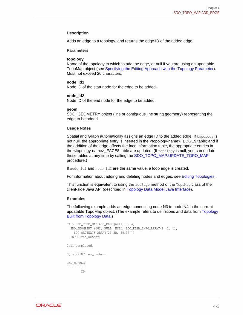
Description
Adds an edge to a topology, and returns the edge ID of the added edge.
Parameters
topologyName of the topology to which to add the edge, or null if you are using an updatableTopoMap object (see Specifying the Editing Approach with the Topology Parameter).Must not exceed 20 characters.
node_id1Node ID of the start node for the edge to be added.
node_id2Node ID of the end node for the edge to be added.
geomSDO_GEOMETRY object (line or contiguous line string geometry) representing theedge to be added.
Usage Notes
Spatial and Graph automatically assigns an edge ID to the added edge. If topology isnot null, the appropriate entry is inserted in the <topology-name>_EDGE$ table; and ifthe addition of the edge affects the face information table, the appropriate entries inthe <topology-name>_FACE$ table are updated. (If topology is null, you can updatethese tables at any time by calling the SDO_TOPO_MAP.UPDATE_TOPO_MAPprocedure.)
If node_id1 and node_id2 are the same value, a loop edge is created.
For information about adding and deleting nodes and edges, see Editing Topologies .
This function is equivalent to using the addEdge method of the TopoMap class of theclient-side Java API (described in Topology Data Model Java Interface).
Examples
The following example adds an edge connecting node N3 to node N4 in the currentupdatable TopoMap object. (The example refers to definitions and data from TopologyBuilt from Topology Data.)
CALL SDO_TOPO_MAP.ADD_EDGE(null, 3, 4, SDO_GEOMETRY(2002, NULL, NULL, SDO_ELEM_INFO_ARRAY(1, 2, 1), SDO_ORDINATE_ARRAY(25,35, 20,37))) INTO :res_number; Call completed. SQL> PRINT res_number; RES_NUMBER ---------- 29
Chapter 4SDO_TOPO_MAP.ADD_EDGE
4-3
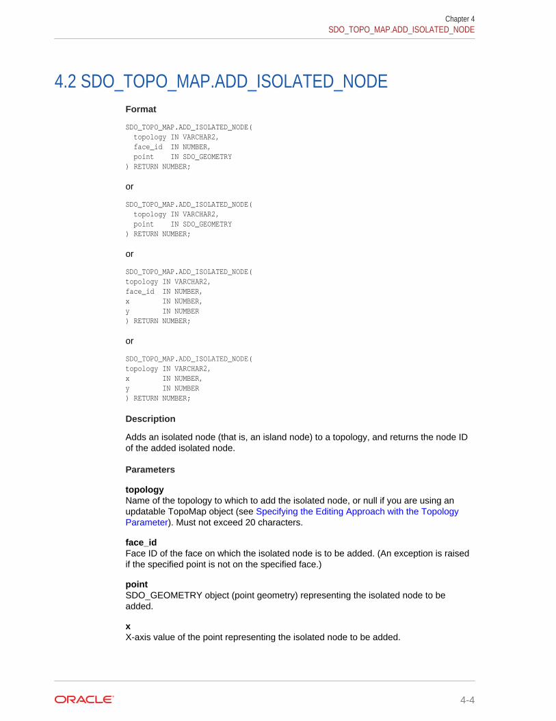
4.2 SDO_TOPO_MAP.ADD_ISOLATED_NODEFormat
SDO_TOPO_MAP.ADD_ISOLATED_NODE( topology IN VARCHAR2, face_id IN NUMBER, point IN SDO_GEOMETRY ) RETURN NUMBER;
or
SDO_TOPO_MAP.ADD_ISOLATED_NODE( topology IN VARCHAR2, point IN SDO_GEOMETRY ) RETURN NUMBER;
or
SDO_TOPO_MAP.ADD_ISOLATED_NODE( topology IN VARCHAR2, face_id IN NUMBER, x IN NUMBER, y IN NUMBER ) RETURN NUMBER;
or
SDO_TOPO_MAP.ADD_ISOLATED_NODE( topology IN VARCHAR2, x IN NUMBER, y IN NUMBER ) RETURN NUMBER;
Description
Adds an isolated node (that is, an island node) to a topology, and returns the node IDof the added isolated node.
Parameters
topologyName of the topology to which to add the isolated node, or null if you are using anupdatable TopoMap object (see Specifying the Editing Approach with the TopologyParameter). Must not exceed 20 characters.
face_idFace ID of the face on which the isolated node is to be added. (An exception is raisedif the specified point is not on the specified face.)
pointSDO_GEOMETRY object (point geometry) representing the isolated node to beadded.
xX-axis value of the point representing the isolated node to be added.
Chapter 4SDO_TOPO_MAP.ADD_ISOLATED_NODE
4-4

yY-axis value of the point representing the isolated node to be added.
Usage Notes
Spatial and Graph automatically assigns a node ID to the added node. If topology isnot null, the appropriate entry is inserted in the <topology-name>_NODE$ table, andthe <topology-name>_FACE$ table is updated to include an entry for the addedisolated node. (If topology is null, you can update these tables at any time by callingthe SDO_TOPO_MAP.UPDATE_TOPO_MAP procedure.)
If you know the ID of the face on which the isolated node is to be added, you canspecify the face_id parameter. If you specify this parameter, there are two benefits:
• Validation: The function checks to see if the point is on the specified face, andraises an exception if it is not. Otherwise, the function checks to see if the point ison any face in the topology, and raises an exception if it is not.
• Performance: The function checks only if the point is on the specified face.Otherwise, it checks potentially all faces in the topology to see if the point is onany face.
To add a non-isolated node, use the SDO_TOPO_MAP.ADD_NODE function.
For information about adding and deleting nodes and edges, see Editing Topologies .
This function is equivalent to using the addIsolatedNode method of the TopoMap classof the client-side Java API (described in Topology Data Model Java Interface).
Examples
The following example adds an isolated node to the right of isolated node N4 on faceF2, and it returns the node ID of the added node. It uses the current updatableTopoMap object. (The example refers to definitions and data from Topology Built fromTopology Data.)
DECLARE result_num NUMBER;BEGINresult_num := SDO_TOPO_MAP.ADD_ISOLATED_NODE(null, 2, SDO_GEOMETRY(2001, NULL, SDO_POINT_TYPE(22,37,NULL), NULL, NULL));DBMS_OUTPUT.PUT_LINE('Result = ' || result_num);END;/Result = 24 PL/SQL procedure successfully completed.
4.3 SDO_TOPO_MAP.ADD_LINEAR_GEOMETRYFormat
SDO_TOPO_MAP.ADD_LINEAR_GEOMETRY( topology IN VARCHAR2, curve IN SDO_GEOMETRY ) RETURN SDO_NUMBER_ARRAY;
or
Chapter 4SDO_TOPO_MAP.ADD_LINEAR_GEOMETRY
4-5

SDO_TOPO_MAP.ADD_LINEAR_GEOMETRY( topology IN VARCHAR2, coords IN SDO_NUMBER_ARRAY ) RETURN SDO_NUMBER_ARRAY;
Description
Adds a linear (line string or multiline string) geometry to the topology, inserting edgesand nodes as necessary based on the full intersection of the geometry with the edgesand nodes in the topology graph, and an array of the edge IDs of the inserted andshared edges in sequence from the start to the end of the geometry.
Parameters
topologyName of the topology to which to add the edge or edges, or null if you are using anupdatable TopoMap object (see Specifying the Editing Approach with the TopologyParameter). Must not exceed 20 characters.
curveSDO_GEOMETRY object (curve or line string geometry) representing the edge oredges to be added.
coordsSDO_NUMBER_ARRAY object specifying the coordinates of the edge or edges to beadded.
Usage Notes
This function creates at least one new edge, and more edges if necessary. Forexample, if the line string geometry intersects an existing edge, two edges are createdfor the added line string, and the existing edge (the one being intersected) is dividedinto two edges. If topology is not null, Spatial and Graph automatically updates the<topology-name>_EDGE$ table as needed. (If topology is null, you can update thistable at any time by calling the SDO_TOPO_MAP.UPDATE_TOPO_MAP procedure.)
This function returns an array of the edge IDs of the inserted and shared edges insequence from the start to the end of the geometry. If a segment in the addedgeometry overlaps an existing edge in the topology, the sign of the returned edgedepends on the directions of the added segment and the existing edge: if the directionof the existing edge is the same as the linear geometry, the returned edge element ispositive; if the direction of the existing edge is the opposite of the linear geometry, thereturned edge element is negative.
An exception is raised if the object in the curve or coords parameter contains any linesegments that run together (overlap) in any manner; however, the line segments cancross at one or more points.
For information about adding and deleting nodes and edges, see Editing Topologies .
This function is equivalent to using the addLinearGeometry method of the TopoMapclass of the client-side Java API (described in Topology Data Model Java Interface).
Examples
The following example adds an edge representing a specified line string geometry,and it returns the edge ID of the added edge. It uses the current updatable TopoMap
Chapter 4SDO_TOPO_MAP.ADD_LINEAR_GEOMETRY
4-6

object. (The example refers to definitions and data from Topology Built from TopologyData.)
SELECT SDO_TOPO_MAP.ADD_LINEAR_GEOMETRY(null, SDO_GEOMETRY(2002, NULL, NULL, SDO_ELEM_INFO_ARRAY(1,2,1), SDO_ORDINATE_ARRAY(50,10, 55,10, 57,11)))FROM DUAL; SDO_TOPO_MAP.ADD_LINEAR_GEOMETRY(NULL,SDO_GEOMETRY(2002,NULL,NULL,SDO_ELEM_INFO_--------------------------------------------------------------------------------SDO_NUMBER_ARRAY(31)
4.4 SDO_TOPO_MAP.ADD_LOOPFormat
SDO_TOPO_MAP.ADD_LOOP( topology IN VARCHAR2, node_id IN NUMBER, geom IN SDO_GEOMETRY ) RETURN NUMBER;
Description
Adds an edge that loops and connects to the same node, and returns the edge ID ofthe added edge.
Parameters
topologyName of the topology to which to add the edge, or null if you are using an updatableTopoMap object (see Specifying the Editing Approach with the Topology Parameter).Must not exceed 20 characters.
node_idNode ID of the node to which to add the edge that will start and end at this node.
geomSDO_GEOMETRY object (line string geometry) representing the edge to be added.The start and end points of the line string must be the same point representingnode_id.
Usage Notes
This function creates a new edge, as well as a new face consisting of the interior of theloop. If the edge is added at an isolated node, the edge is an isolated edge. Iftopology is not null, Spatial and Graph automatically updates the <topology-name>_EDGE$ and <topology-name>_FACE$ tables as needed. (If topology is null,you can update these tables at any time by calling the SDO_TOPO_MAP.UPDATE_TOPO_MAP procedure.)
For information about adding and deleting nodes and edges, see Editing Topologies .
This function is equivalent to using the addLoop method of the TopoMap class of theclient-side Java API (described in Topology Data Model Java Interface).
Chapter 4SDO_TOPO_MAP.ADD_LOOP
4-7
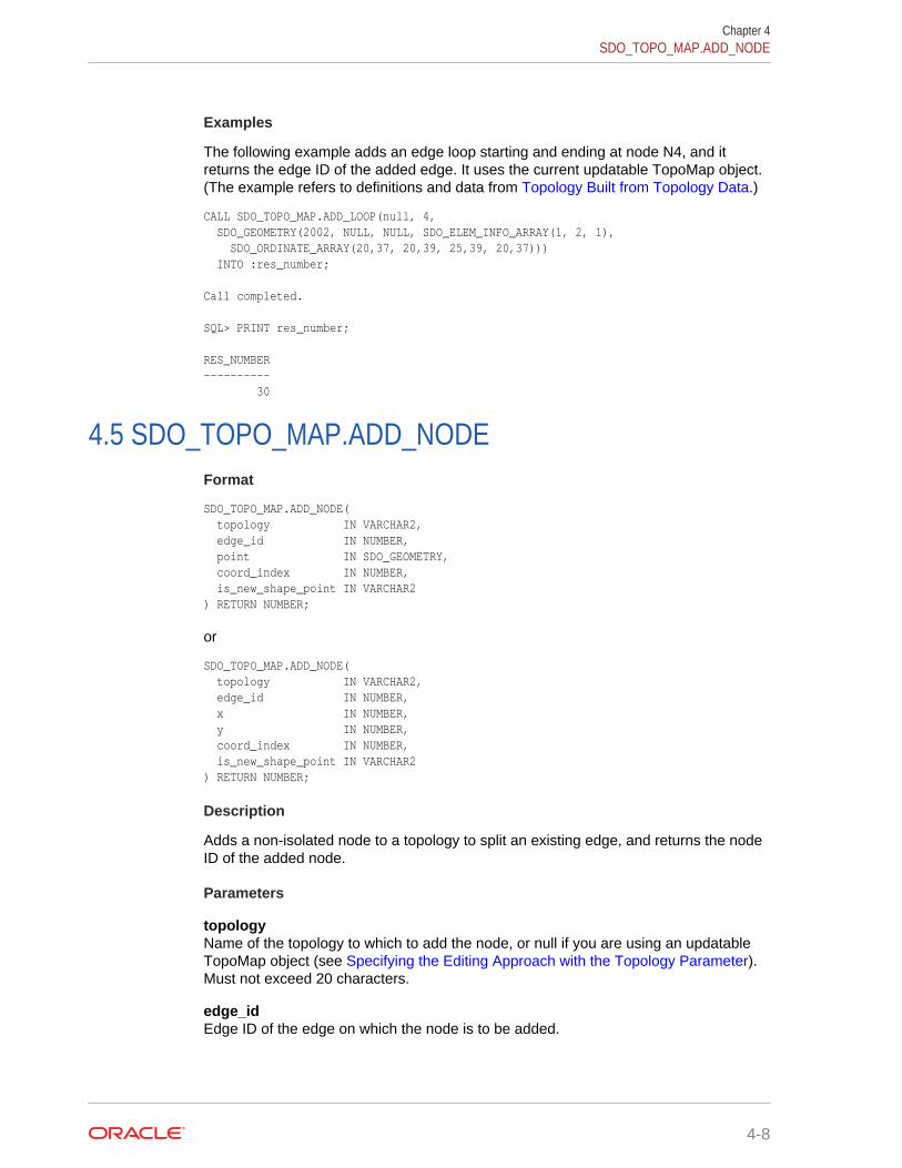
Examples
The following example adds an edge loop starting and ending at node N4, and itreturns the edge ID of the added edge. It uses the current updatable TopoMap object.(The example refers to definitions and data from Topology Built from Topology Data.)
CALL SDO_TOPO_MAP.ADD_LOOP(null, 4, SDO_GEOMETRY(2002, NULL, NULL, SDO_ELEM_INFO_ARRAY(1, 2, 1), SDO_ORDINATE_ARRAY(20,37, 20,39, 25,39, 20,37))) INTO :res_number; Call completed. SQL> PRINT res_number; RES_NUMBER ---------- 30
4.5 SDO_TOPO_MAP.ADD_NODEFormat
SDO_TOPO_MAP.ADD_NODE( topology IN VARCHAR2, edge_id IN NUMBER, point IN SDO_GEOMETRY, coord_index IN NUMBER, is_new_shape_point IN VARCHAR2 ) RETURN NUMBER;
or
SDO_TOPO_MAP.ADD_NODE( topology IN VARCHAR2, edge_id IN NUMBER, x IN NUMBER, y IN NUMBER, coord_index IN NUMBER, is_new_shape_point IN VARCHAR2 ) RETURN NUMBER;
Description
Adds a non-isolated node to a topology to split an existing edge, and returns the nodeID of the added node.
Parameters
topologyName of the topology to which to add the node, or null if you are using an updatableTopoMap object (see Specifying the Editing Approach with the Topology Parameter).Must not exceed 20 characters.
edge_idEdge ID of the edge on which the node is to be added.
Chapter 4SDO_TOPO_MAP.ADD_NODE
4-8
pointSDO_GEOMETRY object (point geometry) representing the node to be added. Thepoint must be an existing shape point or a new point that breaks a line segmentconnecting two consecutive shape points.
xX-axis value of the point representing the node to be added. The point must be anexisting shape point or a new point that breaks a line segment connecting twoconsecutive shape points.
yY-axis value of the point representing the node to be added. The point must be anexisting shape point or a new point that breaks a line segment connecting twoconsecutive shape points.
coord_indexThe index (position) of the array position in the edge coordinate array on or afterwhich the node is to be added. Each vertex (node or shape point) has a position in theedge coordinate array. The start point (node) is index (position) 0, the first point afterthe start point is 1, and so on. (However, the coord_index value cannot be the indexof the last vertex.) For example, if the edge coordinates are (2,2, 5,2, 8,3) the index ofthe second vertex (5,2) is 1.
is_new_shape_pointTRUE if the added node is to be a new shape point following the indexed vertex(coord_index value) of the edge; FALSE if the added node is exactly on the indexedvertex.A value of TRUE lets you add a node at a new point, breaking an edge segment at thecoordinates specified in the point parameter or the x and y parameter pair. A value ofFALSE causes the coordinates in the point parameter or the x and y parameter pair tobe ignored, and causes the node to be added at the existing shape point associatedwith the coord_index value.
Usage Notes
Spatial and Graph automatically assigns a node ID to the added node and creates anew edge. The split piece at the beginning of the old edge is given the edge ID of theold edge. If topology is not null, appropriate entries are inserted in the <topology-name>_NODE$ and <topology-name>_EDGE$ tables. (If topology is null, you canupdate these tables at any time by calling the SDO_TOPO_MAP.UPDATE_TOPO_MAP procedure.)
To add an isolated node (that is, an island node), use the SDO_TOPO_MAP.ADD_ISOLATED_NODE function.
For information about adding and deleting nodes and edges, see Editing Topologies .
This function is equivalent to using the addNode method of the TopoMap class of theclient-side Java API (described in Topology Data Model Java Interface).
Examples
The following example adds a non-isolated node to the right of node N2 on edge E2,and it returns the node ID of the added node. It uses the current updatable TopoMapobject. (The example refers to definitions and data from Topology Built from TopologyData.)
Chapter 4SDO_TOPO_MAP.ADD_NODE
4-9
DECLARE result_num NUMBER;BEGINresult_num := SDO_TOPO_MAP.ADD_NODE(null, 2, SDO_GEOMETRY(2001, NULL, SDO_POINT_TYPE(27,30,NULL), NULL, NULL), 0, 'TRUE');DBMS_OUTPUT.PUT_LINE('Result = ' || result_num);END;/Result = 26 PL/SQL procedure successfully completed.
4.6 SDO_TOPO_MAP.ADD_POINT_GEOMETRYFormat
SDO_TOPO_MAP.ADD_POINT_GEOMETRY( topology IN VARCHAR2, point IN SDO_GEOMETRY ) RETURN NUMBER;
or
SDO_TOPO_MAP.ADD_POINT_GEOMETRY( topology IN VARCHAR2, coord IN SDO_NUMBER_ARRAY ) RETURN NUMBER;
Description
Adds a node representing a specified point geometry or coordinate pair, and returnsthe node ID of the added node.
Parameters
topologyName of the topology to which to add the node, or null if you are using an updatableTopoMap object (see Specifying the Editing Approach with the Topology Parameter).Must not exceed 20 characters.
pointSDO_GEOMETRY object (point geometry) representing the node to be added.
coordSDO_NUMBER_ARRAY object specifying the coordinates of the node to be added.
Usage Notes
If the point coincides with an existing node, no changes are made to the topology.Otherwise, an isolated node or a node splitting an edge is added.
For information about adding and deleting nodes and edges, see Editing Topologies .
This function is equivalent to using the addPointGeometry method of the TopoMap classof the client-side Java API (described in Topology Data Model Java Interface).
Chapter 4SDO_TOPO_MAP.ADD_POINT_GEOMETRY
4-10
Examples
The following example adds a node representing a specified point geometry, and itreturns the node ID of the added node. It uses the current updatable TopoMap object.
SELECT SDO_TOPO_MAP.ADD_POINT_GEOMETRY(null, SDO_GEOMETRY(2001, NULL, SDO_POINT_TYPE(57,12,NULL), NULL, NULL))FROM DUAL; SDO_TOPO_MAP.ADD_POINT_GEOMETRY(NULL,SDO_GEOMETRY(2001,NULL,SDO_POINT_TYPE(57,12-------------------------------------------------------------------------------- 29
The following example adds a node at the specified coordinates (58, 12), and it returnsthe node ID of the added node. It uses the current updatable TopoMap object.
SELECT SDO_TOPO_MAP.ADD_POINT_GEOMETRY(null, SDO_NUMBER_ARRAY(58,12))FROM DUAL; SDO_TOPO_MAP.ADD_POINT_GEOMETRY(NULL,SDO_NUMBER_ARRAY(58,12)) ------------------------------------------------------------- 30
4.7 SDO_TOPO_MAP.ADD_POLYGON_GEOMETRYFormat
SDO_TOPO_MAP.ADD_POLYGON_GEOMETRY( topology IN VARCHAR2, polygon IN SDO_GEOMETRY ) RETURN SDO_NUMBER_ARRAY;
or
SDO_TOPO_MAP.ADD_POLYGON_GEOMETRY( topology IN VARCHAR2, coords IN SDO_NUMBER_ARRAY ) RETURN SDO_NUMBER_ARRAY;
Description
Adds one or more faces representing a specified polygon geometry, and returns theface ID of each added face.
Parameters
topologyName of the topology to which to add the face or faces, or null if you are using anupdatable TopoMap object (see Specifying the Editing Approach with the TopologyParameter). Must not exceed 20 characters.
polygonSDO_GEOMETRY object (polygon or multipolygon geometry) representing the faceor faces to be added. Each polygon in the object must have a single exterior ring thatcan contain any number of interior rings.
Chapter 4SDO_TOPO_MAP.ADD_POLYGON_GEOMETRY
4-11

coordsSDO_NUMBER_ARRAY object specifying the coordinates of a single polygongeometry representing the face or faces to be added. The vertices of the polygonmust be in counterclockwise order, with the last vertex the same as the first vertex.
Usage Notes
This function creates at least one new face, and more faces if necessary. Forexample, if the polygon geometry intersects an existing face, faces are created for theadded polygon, and the existing face (the one being intersected) definition is adjusted.If topology is not null, Spatial and Graph automatically updates the <topology-name>_FACE$ table as needed. (If topology is null, you can update this table at anytime by calling the SDO_TOPO_MAP.UPDATE_TOPO_MAP procedure.)
If the polygon coincides with an existing face, no changes are made to the topology.
For a multipolygon geometry, no exterior ring may overlap any other exterior ring. Forexample, you cannot add a face representing the following single multipolygongeometry: a park (exterior ring) containing a lake (interior ring) with an island in thelake (exterior ring inside the preceding interior ring).
This function is equivalent to using the addPolygonGeometry method of the TopoMapclass of the client-side Java API (described in Topology Data Model Java Interface).
Examples
The following example adds a face representing a specified polygon geometry, and itreturns and prints the face ID of the added edge. It uses the current updatableTopoMap object.
DECLARE res_number_array SDO_NUMBER_ARRAY; face_count NUMBER; face_ctr NUMBER; this_face NUMBER;BEGINres_number_array := SDO_TOPO_MAP.ADD_POLYGON_GEOMETRY(null, SDO_GEOMETRY(2003, NULL, NULL, SDO_ELEM_INFO_ARRAY(1,1003,1), SDO_ORDINATE_ARRAY(61,10, 70,10, 70,15, 65,15, 61,10)));-- DBMS_OUTPUT.PUT_LINE('Result = ' || res_number_array);-- Print each face associated with the geometry.face_count := res_number_array.count;for face_ctr in 1..face_count loop this_face := res_number_array(face_ctr); dbms_output.put_line ('this face = '|| this_face); end loop; -- printed each faceEND;/this face = 12
4.8 SDO_TOPO_MAP.CHANGE_EDGE_COORDSFormat
SDO_TOPO_MAP.CHANGE_EDGE_COORDS( topology IN VARCHAR2, edge_id IN NUMBER, geom IN SDO_GEOMETRY);
Chapter 4SDO_TOPO_MAP.CHANGE_EDGE_COORDS
4-12
or
SDO_TOPO_MAP.CHANGE_EDGE_COORDS( topology IN VARCHAR2, edge_id IN NUMBER, geom IN SDO_GEOMETRY, moved_iso_nodes OUT SDO_NUMBER_ARRAY, moved_iso_edges OUT SDO_NUMBER_ARRAY, allow_iso_moves IN VARCHAR2);
Description
Changes the coordinates and related information about an edge.
Parameters
topologyName of the topology containing the edge, or null if you are using an updatableTopoMap object (see Specifying the Editing Approach with the Topology Parameter).Must not exceed 20 characters.
edge_idEdge ID of the edge whose coordinates are to be changed.
geomSDO_GEOMETRY object (line or contiguous line string geometry) representing themodified edge. The start and end points of the modified edge must be the same as forthe original edge.
moved_iso_nodesOutput parameter in which, if the allow_iso_moves parameter value is TRUE, Spatialand Graph stores the node ID values of any isolated nodes that have moved to adifferent face as a result of this procedure. If the allow_iso_moves parameter value isFALSE, Spatial and Graph stores the node ID values of any isolated nodes that did notmove but that would have moved to a different face if the allow_iso_moves parametervalue had been TRUE.
moved_iso_edgesOutput parameter in which, if the allow_iso_moves parameter value is TRUE, Spatialand Graph stores the edge ID values of any isolated edges that have moved to adifferent face as a result of this procedure. If the allow_iso_moves parameter value isFALSE, Spatial and Graph stores the edge ID values of any isolated edges that did notmove but that would have moved to a different face if the allow_iso_moves parametervalue had been TRUE.
allow_iso_movesTRUE causes Spatial and Graph to allow an edge coordinates change operation thatwould cause any isolated nodes or edges to be in a different face, and to adjust thecontaining face information for such isolated nodes and edges; FALSE causes Spatialand Graph not to allow an edge coordinates change operation that would cause anyisolated nodes or edges to be in a different face.If you use the format that does not include the allow_iso_moves parameter, Spatialand Graph allows edge move operations that would cause any isolated nodes oredges to be in a different face, and it adjusts the containing face information for suchisolated nodes and edges.
Chapter 4SDO_TOPO_MAP.CHANGE_EDGE_COORDS
4-13

Usage Notes
If this procedure modifies a boundary between faces, Spatial and Graph automaticallyperforms the following operations and updates the Topology Data Model tables asneeded: reassigning island nodes and faces, and adjusting the MBRs of the faces onboth sides.
If topology is not null, this procedure modifies the information about the specifiededge in the <topology-name>_EDGE$ table (described in Edge Information Table). (Iftopology is null, you can update this table at any time by calling the SDO_TOPO_MAP.UPDATE_TOPO_MAP procedure.)
You cannot use this procedure to change the start point or the end point, or both, ofthe specified edge. To do any of these operations, you must delete the edge, deletethe node or nodes for the start or end point (or both) to be changed, add the necessarynew node or nodes, and add the edge.
For information about editing topological elements, see Editing Topologies .
This procedure is equivalent to using the changeEdgeCoords method of the TopoMapclass of the client-side Java API (described in Topology Data Model Java Interface).
Examples
The following example changes the coordinates of edge E1. (It changes only the thirdpoint, from 16,38 to 16,39.) It uses the current updatable TopoMap object. (Theexample refers to definitions and data from Topology Built from Topology Data.)
CALL SDO_TOPO_MAP.CHANGE_EDGE_COORDS(null, 1, SDO_GEOMETRY(2002, NULL, NULL, SDO_ELEM_INFO_ARRAY(1, 2, 1), SDO_ORDINATE_ARRAY(8,30, 16,30, 16,39, 3,38, 3,30, 8,30)));
4.9 SDO_TOPO_MAP.CLEAR_TOPO_MAPFormat
SDO_TOPO_MAP.CLEAR_TOPO_MAP( topo_map IN VARCHAR2);
Description
Clears all objects and changes in the cache associated with a TopoMap object.
Parameters
topo_mapName of the TopoMap object. (TopoMap objects are explained in TopoMap Objects.)
Usage Notes
If the TopoMap object is updatable, this procedure changes it to be read-only.
For information about using an in-memory cache to edit topological elements, see Approaches for Editing Topology Data.
Contrast this procedure with the SDO_TOPO_MAP.UPDATE_TOPO_MAP procedure,which applies the changes in the cache associated with the TopoMap object to thetopology. You cannot call the SDO_TOPO_MAP.CLEAR_TOPO_MAP procedure if
Chapter 4SDO_TOPO_MAP.CLEAR_TOPO_MAP
4-14

you previously used the SDO_TOPO_MAP.UPDATE_TOPO_MAP procedure on thespecified TopoMap object.
This procedure is equivalent to using the clearCache method of the TopoMap class ofthe client-side Java API (described in Topology Data Model Java Interface).
Examples
The following example clears the cache associated with the TopoMap object namedCITY_DATA_TOPOMAP, which is associated with the topology named CITY_DATA. (Theexample refers to definitions and data from Topology Built from Topology Data.)
CALL SDO_TOPO_MAP.CLEAR_TOPO_MAP('CITY_DATA_TOPOMAP');
4.10 SDO_TOPO_MAP.COMMIT_TOPO_MAPFormat
SDO_TOPO_MAP.COMMIT_TOPO_MAP;
Description
Updates the topology to reflect changes made to the current updatable TopoMapobject, commits all changes to the database, and makes the TopoMap object read-only.
Parameters
None.
Usage Notes
Use this procedure when you are finished with a batch of edits to a topology and youwant to commit all changes to the database. After the commit operation completes,you cannot edit the TopoMap object. To make further edits to the topology, you musteither clear the cache (using the SDO_TOPO_MAP.CLEAR_TOPO_MAP procedure)or create a new TopoMap object (using the SDO_TOPO_MAP.CREATE_TOPO_MAPprocedure), and then load the topology into the TopoMap object for update (using the SDO_TOPO_MAP.LOAD_TOPO_MAP function or procedure).
Contrast this procedure with the SDO_TOPO_MAP.UPDATE_TOPO_MAP procedure,which leaves the TopoMap object available for editing operations and which does notperform a commit operation (and thus does not end the database transaction).
To roll back all TopoMap object changes, use the SDO_TOPO_MAP.ROLLBACK_TOPO_MAP procedure.
For information about using an in-memory cache to edit topological elements, see Approaches for Editing Topology Data.
This procedure is equivalent to using the commitDB method of the TopoMap class of theclient-side Java API (described in Topology Data Model Java Interface).
Examples
The following example commits to the database all changes to the current updatableTopoMap object, and prevents further editing of the TopoMap object.
EXECUTE SDO_TOPO_MAP.COMMIT_TOPO_MAP;
Chapter 4SDO_TOPO_MAP.COMMIT_TOPO_MAP
4-15

4.11 SDO_TOPO_MAP.CREATE_EDGE_INDEXFormat
SDO_TOPO_MAP.CREATE_EDGE_INDEX( topo_map IN VARCHAR2);
Description
Creates an internal R-tree index (or rebuilds the index if one already exists) on theedges in the cache associated with a TopoMap object.
Parameters
topo_mapName of the TopoMap object. (TopoMap objects are explained in TopoMap Objects.)
Usage Notes
You can cause Spatial and Graph to create in-memory R-tree indexes to be built onthe edges and faces in the specified TopoMap object. These indexes use somememory resources and take some time to create; however, they significantly improveperformance if you edit a large number of topological elements in the session. Theycan also improve performance for queries that use a read-only TopoMap object. If theTopoMap object is updatable and if you are performing many editing operations, youshould probably rebuild the indexes periodically; however, if the TopoMap object willnot be updated, create the indexes when or after loading the read-only TopoMapobject or after calling the SDO_TOPO_MAP.COMMIT_TOPO_MAP procedure.
Compare this procedure with the SDO_TOPO_MAP.CREATE_FACE_INDEXprocedure, which creates an internal R-tree index (or rebuilds the index if one alreadyexists) on the faces in the cache associated with a TopoMap object.
This procedure is equivalent to using the createEdgeIndex method of the TopoMapclass of the client-side Java API (described in Topology Data Model Java Interface).
Examples
The following example creates an internal R-tree index (or rebuilds the index if onealready exists) on the edges in the cache associated with the TopoMap object namedCITY_DATA_TOPOMAP, which is associated with the topology named CITY_DATA. (Theexample refers to definitions and data from Topology Built from Topology Data.)
CALL SDO_TOPO_MAP.CREATE_EDGE_INDEX('CITY_DATA_TOPOMAP');
4.12 SDO_TOPO_MAP.CREATE_FACE_INDEXFormat
SDO_TOPO_MAP.CREATE_FACE_INDEX( topo_map IN VARCHAR2);
Description
Creates an internal R-tree index (or rebuilds the index if one already exists) on thefaces in the cache associated with a TopoMap object.
Chapter 4SDO_TOPO_MAP.CREATE_EDGE_INDEX
4-16

Parameters
topo_mapName of the TopoMap object. (TopoMap objects are explained in TopoMap Objects.)
Usage Notes
You can cause Spatial and Graph to create in-memory R-tree indexes to be built onthe edges and faces in the specified TopoMap object. These indexes use somememory resources and take some time to create; however, they significantly improveperformance if you edit a large number of topological elements in the session. Theycan also improve performance for queries that use a read-only TopoMap object. If theTopoMap object is updatable and if you are performing many editing operations, youshould probably rebuild the indexes periodically; however, if the TopoMap object willnot be updated, create the indexes when or after loading the read-only TopoMapobject or after calling the SDO_TOPO_MAP.COMMIT_TOPO_MAP procedure.
Compare this procedure with the SDO_TOPO_MAP.CREATE_EDGE_INDEXprocedure, which creates an internal R-tree index (or rebuilds the index if one alreadyexists) on the edges in the cache associated with a TopoMap object.
This procedure is equivalent to using the createFaceIndex method of the TopoMapclass of the client-side Java API (described in Topology Data Model Java Interface).
Examples
The following example creates an internal R-tree index (or rebuilds the index if onealready exists) on the faces in the cache associated with the TopoMap object namedCITY_DATA_TOPOMAP, which is associated with the topology named CITY_DATA. (Theexample refers to definitions and data from Topology Built from Topology Data.)
CALL SDO_TOPO_MAP.CREATE_FACE_INDEX('CITY_DATA_TOPOMAP');
4.13 SDO_TOPO_MAP.CREATE_FEATUREFormat (no topology geometry layer hierarchy or lowest level in a hierarchy)
SDO_TOPO_MAP.CREATE_FEATURE( topology IN VARCHAR2, table_name IN VARCHAR2, column_name IN VARCHAR2, geom IN SDO_GEOMETRY ) RETURN SDO_TOPO_GEOMETRY;orSDO_TOPO_MAP.CREATE_FEATURE( topology IN VARCHAR2, table_name IN VARCHAR2, column_name IN VARCHAR2, geom IN SDO_GEOMETRY, snapfeature IN NUMBER ) RETURN SDO_TOPO_GEOMETRY;
Format (parent level in a hierarchy)
SDO_TOPO_MAP.CREATE_FEATURE( topology IN VARCHAR2, table_name IN VARCHAR2,
Chapter 4SDO_TOPO_MAP.CREATE_FEATURE
4-17

column_name IN VARCHAR2, dml_condition IN VARCHAR2 ) RETURN SDO_TOPO_GEOMETRY;
Description
Creates a feature from Oracle Spatial and Graph geometries. (This function isintended to be used for inserting rows into a feature table.)
• The first two formats (with the geom parameter and without the dml_conditionparameter) are for creating a feature in a topology without a topology geometrylayer hierarchy or in the lowest level of a topology with a topology geometry layerhierarchy.
• The third format (with the dml_condition parameter and without the geomparameter) is for creating a feature in a parent level of a topology with a topologygeometry layer hierarchy.
Parameters
topologyTopology having the associated specified feature table and feature column.
table_nameName of the feature table containing the feature column specified in column_name.
column_nameName of the feature column (of type SDO_TOPO_GEOMETRY) containing thetopology geometries.
geomGeometry objects.
snapfeatureIf set to 1, the specified new feature is snapped to existing edges and nodes in thetopology.
dml_conditionFor topologies with a topology geometry layer hierarchy (described in TopologyGeometry Layer Hierarchy): DML condition for selecting rows from a child layer to beinserted into a parent layer. Specify the condition in a quoted string, but without theword WHERE. For example, to select only rows where the STATE_ABBR columnvalue is MA, specify the following: 'state_abbr=''MA'''
Usage Notes
This function is used to create features from existing geometries stored in a spatialtable. Creating features from existing geometries is one approach to creating topologyfeatures; the other approach is to load the topology data into the node, edge, and faceinformation tables. Both approaches are described in Main Steps in Using TopologyData, which contains the following subsections:
• Using a Topology Built from Topology Data
• Using a Topology Built from Spatial Geometries (that is, the approach using theCREATE_FEATURE function)
When you use the first or second format of this function, you must first create and loadan updatable TopoMap object. To create a topology feature or an associated
Chapter 4SDO_TOPO_MAP.CREATE_FEATURE
4-18
topological element, the function internally calls the addPointGeometry,addLinearGeometry, or addPolygonGeometry method of the updatable TopoMapobject, depending on the SDO_GTYPE value of the geometry object, and it calls theupdateTopology method of the updatable TopoMap object to write topologicalelements to the database. If this function is called in an INSERT or UPDATEstatement, a feature is created or updated in the feature table. When the functioncompletes, it has the effect of overlaying the geometry onto the topology. (That is,Spatial and Graph uses an implicitly created TopoMap object to create a newTopoMap object for each call to this function.)
When you use the third format of this function, you do not need to create an updatableTopoMap object. The function internally collects TG_ID values of features in the childlevel based on the dml_condition parameter value, and it assembles anSDO_TGL_OBJECT_ARRAY object to create the SDO_GEOMETRY object.
To ensure that this function works correctly with all geometries, use a loop to call thefunction for each geometry. Do not use this function in a subquery in an INSERT orUPDATE statement, because doing so may cause inconsistencies in the topology, andyou may not receive any error or warning messages about the inconsistencies.
An exception is raised if one or more of the following conditions exist:
• topology, table_name, or column_name does not exist.
• geom specifies geometry objects of a type inconsistent with the topology geometrylayer type. For example, you cannot use line string geometries to create landparcel features.
• dml_condition is used with a topology that does not have a topology geometrylayer hierarchy.
• The input geometries include any optimized shapes, such as optimized rectanglesor circles.
• A line string or multiline string geometry contains any overlapping line segments.
• In a multipolygon geometry, an exterior ring overlaps any other exterior ring.
Examples
The following example populates the FEATURE column in the CITY_STREETS,TRAFFIC_SIGNS, and LAND_PARCELS feature tables with all geometries in theGEOMETRY column in the CITY_STREETS_GEOM, TRAFFIC_SIGNS_GEOM, andLAND_PARCELS_GEOM spatial tables, respectively. This example assumes that anupdatable TopoMap object has been created and loaded for the CITY_DATA topology.(The example refers to definitions and data from Topology Built from SpatialGeometries.)
BEGIN FOR street_rec IN (SELECT name, geometry FROM city_streets_geom) LOOP INSERT INTO city_streets VALUES(street_rec.name, SDO_TOPO_MAP.CREATE_FEATURE('CITY_DATA', 'CITY_STREETS', 'FEATURE', street_rec.geometry)); END LOOP; FOR sign_rec IN (SELECT name, geometry FROM traffic_signs_geom) LOOP INSERT INTO traffic_signs VALUES(sign_rec.name, SDO_TOPO_MAP.CREATE_FEATURE('CITY_DATA', 'TRAFFIC_SIGNS', 'FEATURE', sign_rec.geometry)); END LOOP;
Chapter 4SDO_TOPO_MAP.CREATE_FEATURE
4-19
FOR parcel_rec IN (SELECT name, geometry FROM land_parcels_geom) LOOP INSERT INTO land_parcels VALUES(parcel_rec.name, SDO_TOPO_MAP.CREATE_FEATURE('CITY_DATA', 'LAND_PARCELS', 'FEATURE', parcel_rec.geometry)); END LOOP;END;/
The following example creates a topology that has a topology geometry layerhierarchy with two layers: counties and states. The calls to the CREATE_FEATUREfunction that create parent layer (state) features include the dml_condition parameter(for example, 'p_name=''NH''').
declare name varchar2(64); cursor c1 is select state_abrv, county from counties order by 1, 2; stateabrv varchar2(2);begin -- Initialize. sdo_topo_map.create_topo_map('cnty', 'm2', 10000, 10000, 10000); sdo_topo_map.load_topo_map('m2', -180, -90, 180, 90, 'true'); -- Insert one county at a time. for cnty_rec in c1 loop stateabrv := cnty_rec.state_abrv; name := cnty_rec.county; insert into cnty_areas select state_abrv || '-' ||county, sdo_topo_map.create_feature('CNTY', 'CNTY_AREAS', 'FEATURE', geom) from counties where state_abrv=stateabrv and county=name; end loop; -- Roll back topology. sdo_topo_map.rollback_topo_map(); sdo_topo_map.drop_topo_map('m2'); -- Roll back inserts. rollback; exception when others then dbms_output.put_line(SQLERRM); sdo_topo_map.rollback_topo_map(); sdo_topo_map.drop_topo_map('m2'); rollback;end;/ -- Add parent feature layer.-- -- The following commented out statement can be used to populate the-- child_layer_id parameter in sdo_topo.add_topo_geometry_layer.-- -- select tg_layer_id-- from user_sdo_topo_info -- where TOPOLOGY = 'SC' -- and table_name = 'SC_AREAS';-- execute sdo_topo.add_topo_geometry_layer('SC','SC_P_AREAS', 'FEATURE', - 'POLYGON', NULL, child_layer_id => 1);
Chapter 4SDO_TOPO_MAP.CREATE_FEATURE
4-20
-- Create and insert state features (logically) from county features.insert into sc_p_areas (f_name, p_name, feature) values ('NH', 'US', sdo_topo_map.create_feature('SC','SC_P_AREAS','FEATURE','p_name=''NH'''));insert into sc_p_areas (f_name, p_name, feature) values ('CT', 'US', sdo_topo_map.create_feature('SC','SC_P_AREAS','FEATURE','p_name=''CT'''));insert into sc_p_areas (f_name, p_name, feature) values ('ME', 'US', sdo_topo_map.create_feature('SC','SC_P_AREAS','FEATURE','p_name=''ME'''));insert into sc_p_areas (f_name, p_name, feature) values ('MA', 'US', sdo_topo_map.create_feature('SC','SC_P_AREAS','FEATURE','p_name=''MA'''));commit;
4.14 SDO_TOPO_MAP.CREATE_TOPO_MAPFormat
SDO_TOPO_MAP.CREATE_TOPO_MAP( topology IN VARCHAR2, topo_map IN VARCHAR2, number_of_edges IN NUMBER DEFAULT 100, number_of_nodes IN NUMBER DEFAULT 80, number_of_faces IN NUMBER DEFAULT 30);
Description
Creates a TopoMap object cache associated with an existing topology.
Parameters
topologyName of the topology. Must not exceed 20 characters.
topo_mapName of the TopoMap object. (TopoMap objects are explained in TopoMap Objects.)
number_of_edgesAn estimate of the maximum number of edges that will be in the TopoMap object atany given time. If you do not specify this parameter, a default value of 100 is used.
number_of_nodesAn estimate of the maximum number of nodes that will be in the TopoMap object atany given time. If you do not specify this parameter, a default value of 80 is used.
number_of_facesAn estimate of the maximum number of faces that will be in the TopoMap object atany given time. If you do not specify this parameter, a default value of 30 is used.
Usage Notes
The number_of_edges, number_of_nodes, and number_of_faces parameters let youimprove the performance and memory usage of the procedure when you have a goodidea of the approximate number of edges, nodes, or faces (or any combination) thatwill be placed in the cache associated with the specified TopoMap object. Spatial andGraph initially allocates memory cache for the specified or default number of objects ofeach type, and incrementally increases the allocation later if more objects need to beaccommodated.
Chapter 4SDO_TOPO_MAP.CREATE_TOPO_MAP
4-21

You can create more than one TopoMap object in a user session; however, there canbe no more than one updatable TopoMap object at any given time in a user session.
For information about using an in-memory cache to edit topological elements, see Approaches for Editing Topology Data.
Using this procedure is equivalent to calling the constructor of the TopoMap class of theclient-side Java API (described in Topology Data Model Java Interface).
Examples
The following example creates a TopoMap object named CITY_DATA_TOPOMAP and itsassociated cache, and it associates the TopoMap object with the topology namedCITY_DATA. (The example refers to definitions and data from Topology Built fromTopology Data.)
CALL SDO_TOPO_MAP.CREATE_TOPO_MAP('CITY_DATA', 'CITY_DATA_TOPOMAP');
4.15 SDO_TOPO_MAP.DROP_TOPO_MAPFormat
SDO_TOPO_MAP.DROP_TOPO_MAP( topo_map IN VARCHAR2);
Description
Deletes a TopoMap object from the current user session.
Parameters
topo_mapName of the TopoMap object. (TopoMap objects are explained in TopoMap Objects.)
Usage Notes
This procedure rolls back any uncommitted changes if the TopoMap object isupdatable (that is, performs the equivalent of an SDO_TOPO_MAP.ROLLBACK_TOPO_MAP operation). It clears the cacheassociated with the TopoMap object, and removes the TopoMap object from thesession.
For information about using an in-memory cache to edit topological elements, see Approaches for Editing Topology Data.
Using this procedure is equivalent to setting the variable of the TopoMap object to anull value in a client-side Java application. (The client-side Java API is described in Topology Data Model Java Interface.)
Examples
The following example drops the TopoMap object named CITY_DATA_TOPOMAP. (Theexample refers to definitions and data from Topology Built from Topology Data.)
CALL SDO_TOPO_MAP.DROP_TOPO_MAP('CITY_DATA_TOPOMAP');
Chapter 4SDO_TOPO_MAP.DROP_TOPO_MAP
4-22
4.16 SDO_TOPO_MAP.GET_CONTAINING_FACEFormat
SDO_TOPO_MAP.GET_CONTAINING_FACE( topology IN VARCHAR2, topo_map IN VARCHAR2, point IN SDO_GEOMETRY ) RETURN NUMBER;
or
SDO_TOPO_MAP.GET_CONTAINING_FACE( topology IN VARCHAR2, topo_map IN VARCHAR2, x IN NUMBER, y IN NUMBER ) RETURN NUMBER;
Description
Returns the face ID number of the face that contains the specified point.
Parameters
topologyName of the topology that contains the face and the point, or a null value, asexplained in Using GET_xxx Topology Functions. Must not exceed 20 characters.
topo_mapName of the TopoMap object, or a null value, as explained in Using GET_xxxTopology Functions. (TopoMap objects are explained in TopoMap Objects.)
pointGeometry object specifying the point.
xX-axis value of the point.
yY-axis value of the point.
Usage Notes
The topology or topo_map parameter should specify a valid name, as explained in Using GET_xxx Topology Functions.
This function determines, from the faces in the specified TopoMap object (includingany island faces), which one face (if any) contains the specified point in its open set,excluding islands. (The open set, excluding islands, of a face consists of all pointsinside, but not on the boundary of, the face.) If the point is exactly on the boundary of aface, the function returns a value of 0 (zero).
If the entire topology has been loaded into the TopoMap object and if the point is not inany finite face in the cache, this function returns a value of -1 (for the universe face). Ifa window from the topology has been loaded into the TopoMap object and if the pointis not in any finite face in the cache, this function returns a value of -1 (for the universe
Chapter 4SDO_TOPO_MAP.GET_CONTAINING_FACE
4-23

face) if the point is inside the window and a value of 0 (zero) if the point is outside thewindow. If neither the entire topology nor a window has been loaded, this functionreturns 0 (zero).
This function is equivalent to using the getContainingFace method of the TopoMapclass of the client-side Java API (described in Topology Data Model Java Interface).
Examples
The following example returns the face ID number of the face that contains the point at(22, 37) in the CITY_DATA_TOPOMAP TopoMap object. (The example refers to definitionsand data from Topology Built from Topology Data.)
SELECT SDO_TOPO_MAP.GET_CONTAINING_FACE(null, 'CITY_DATA_TOPOMAP', SDO_GEOMETRY(2001, NULL, SDO_POINT_TYPE(22,37,NULL), NULL, NULL)) FROM DUAL; SDO_TOPO_MAP.GET_CONTAINING_FACE(NULL,'CITY_DATA_TOPOMAP',SDO_GEOMETRY(2001,NULL-------------------------------------------------------------------------------- 2
4.17 SDO_TOPO_MAP.GET_EDGE_ADDITIONSFormat
SDO_TOPO_MAP.GET_EDGE_ADDITIONS() RETURN SDO_NUMBER_ARRAY;
Description
Returns an array of edge ID numbers of edges that have been added to the currentupdatable TopoMap object.
Parameters
None.
Usage Notes
This function returns the edge ID numbers of edges in the current updatable TopoMapobject that have been added since the object was most recently loaded (using SDO_TOPO_MAP.LOAD_TOPO_MAP), updated (using SDO_TOPO_MAP.UPDATE_TOPO_MAP), cleared (using SDO_TOPO_MAP.CLEAR_TOPO_MAP), committed (using SDO_TOPO_MAP.COMMIT_TOPO_MAP), or rolled back (using SDO_TOPO_MAP.ROLLBACK_TOPO_MAP). If there have been no additions duringthat time, the function returns an empty SDO_NUMBER_ARRAY object.
This function is equivalent to using the getEdgeAdditions method of the TopoMap classof the client-side Java API (described in Topology Data Model Java Interface).
Examples
The following example returns the edge ID numbers of edges that have been added tothe current updatable TopoMap object.
SELECT SDO_TOPO_MAP.GET_EDGE_ADDITIONS FROM DUAL; GET_EDGE_ADDITIONS
Chapter 4SDO_TOPO_MAP.GET_EDGE_ADDITIONS
4-24
--------------------------------------------------------------------------------SDO_NUMBER_ARRAY(28, 29, 30, 32)
4.18 SDO_TOPO_MAP.GET_EDGE_CHANGESFormat
SDO_TOPO_MAP.GET_EDGE_CHANGES() RETURN SDO_NUMBER_ARRAY;
Description
Returns an array of edge ID numbers of edges that have been changed (modified) inthe current updatable TopoMap object.
Parameters
None.
Usage Notes
This function returns the edge ID numbers of edges in the current updatable TopoMapobject that have been changed since the object was most recently loaded (using SDO_TOPO_MAP.LOAD_TOPO_MAP), updated (using SDO_TOPO_MAP.UPDATE_TOPO_MAP), cleared (using SDO_TOPO_MAP.CLEAR_TOPO_MAP), committed (using SDO_TOPO_MAP.COMMIT_TOPO_MAP), or rolled back (using SDO_TOPO_MAP.ROLLBACK_TOPO_MAP). If there have been no changes duringthat time, the function returns an empty SDO_NUMBER_ARRAY object.
This function is equivalent to using the getEdgeChanges method of the TopoMap classof the client-side Java API (described in Topology Data Model Java Interface).
Examples
The following example returns the edge ID numbers of edges that have been changedin the current updatable TopoMap object.
SELECT SDO_TOPO_MAP.GET_EDGE_CHANGES FROM DUAL; GET_EDGE_CHANGES --------------------------------------------------------------------------------SDO_NUMBER_ARRAY(3, 2, 1)
4.19 SDO_TOPO_MAP.GET_EDGE_COORDSFormat
SDO_TOPO_MAP.GET_EDGE_COORDS( topology IN VARCHAR2, topo_map IN VARCHAR2, edge_id IN NUMBER ) RETURN SDO_NUMBER_ARRAY;
Description
Returns an array with the coordinates of the start node, shape points, and end nodefor the specified edge.
Chapter 4SDO_TOPO_MAP.GET_EDGE_CHANGES
4-25

Parameters
topologyName of the topology that contains the edge, or a null value, as explained in UsingGET_xxx Topology Functions. Must not exceed 20 characters.
topo_mapName of the TopoMap object, or a null value, as explained in Using GET_xxxTopology Functions. (TopoMap objects are explained in TopoMap Objects.)
edge_idEdge ID value of the edge.
Usage Notes
The topology or topo_map parameter should specify a valid name, as explained in Using GET_xxx Topology Functions.
This function is equivalent to using the getEdgeCoords method of the TopoMap class ofthe client-side Java API (described in Topology Data Model Java Interface).
Examples
The following example returns the coordinates of the start node, shape points, and endnode for the edge whose edge ID value is 1. The returned array contains coordinatesfor six points. (The example refers to definitions and data from Topology Built fromTopology Data.)
SELECT SDO_TOPO_MAP.GET_EDGE_COORDS(null, 'CITY_DATA_TOPOMAP', 1) FROM DUAL; SDO_TOPO_MAP.GET_EDGE_COORDS(NULL,'CITY_DATA_TOPOMAP',1) --------------------------------------------------------------------------------SDO_NUMBER_ARRAY(8, 30, 16, 30, 16, 38, 3, 38, 3, 30, 8, 30)
4.20 SDO_TOPO_MAP.GET_EDGE_DELETIONSFormat
SDO_TOPO_MAP.GET_EDGE_DELETIONS() RETURN SDO_NUMBER_ARRAY;
Description
Returns an array of edge ID numbers of edges that have been deleted from thecurrent updatable TopoMap object.
Parameters
None.
Usage Notes
This function returns the edge ID numbers of edges in the current updatable TopoMapobject that have been deleted since the object was most recently loaded (using SDO_TOPO_MAP.LOAD_TOPO_MAP), updated (using SDO_TOPO_MAP.UPDATE_TOPO_MAP), cleared (using SDO_TOPO_MAP.CLEAR_TOPO_MAP), committed (using SDO_TOPO_MAP.COMMIT_TOPO_MAP), or rolled back (using
Chapter 4SDO_TOPO_MAP.GET_EDGE_DELETIONS
4-26
SDO_TOPO_MAP.ROLLBACK_TOPO_MAP). If there have been no deletions duringthat time, the function returns an empty SDO_NUMBER_ARRAY object.
This function is equivalent to using the getEdgeDeletions method of the TopoMap classof the client-side Java API (described in Topology Data Model Java Interface).
Examples
The following example returns the edge ID numbers of edges that have been deletedfrom the current updatable TopoMap object. In this case, the return of an emptySDO_NUMBER_ARRAY object indicates that no edges have been deleted.
SELECT SDO_TOPO_MAP.GET_EDGE_DELETIONS FROM DUAL; GET_EDGE_DELETIONS --------------------------------------------------------------------------------SDO_NUMBER_ARRAY()
4.21 SDO_TOPO_MAP.GET_EDGE_NODESFormat
SDO_TOPO_MAP.GET_EDGE_NODES( topology IN VARCHAR2, topo_map IN VARCHAR2, edge_id IN NUMBER ) RETURN SDO_NUMBER_ARRAY;
Description
Returns an array with the ID numbers of the start and end nodes on the specifiededge.
Parameters
topologyName of the topology that contains the edge, or a null value, as explained in UsingGET_xxx Topology Functions. Must not exceed 20 characters.
topo_mapName of the TopoMap object, or a null value, as explained in Using GET_xxxTopology Functions. (TopoMap objects are explained in TopoMap Objects.)
edge_idEdge ID value of the edge.
Usage Notes
The topology or topo_map parameter should specify a valid name, as explained in Using GET_xxx Topology Functions.
If the edge starts and ends at a node, the ID number of the node is the first and lastnumber in the array.
This function has no exact equivalent method in the TopoMap class of the client-sideJava API (described in Topology Data Model Java Interface). The getEdge methodreturns a Java edge object of the oracle.spatial.topo.Edge class.
Chapter 4SDO_TOPO_MAP.GET_EDGE_NODES
4-27
Examples
The following example returns the ID numbers of the nodes on the edge whose edgeID value is 1. The returned array contains two nodes ID numbers, both of them 1 (forthe same node), because the specified edge starts and ends at the node with node ID1 and has a loop edge. (The example refers to definitions and data from Topology Builtfrom Topology Data.)
SELECT SDO_TOPO_MAP.GET_EDGE_NODES(null, 'CITY_DATA_TOPOMAP', 1) FROM DUAL; SDO_TOPO_MAP.GET_EDGE_NODES(NULL,'CITY_DATA_TOPOMAP',1) --------------------------------------------------------------------------------SDO_NUMBER_ARRAY(1, 1)
4.22 SDO_TOPO_MAP.GET_FACE_ADDITIONSFormat
SDO_TOPO_MAP.GET_FACE_ADDITIONS() RETURN SDO_NUMBER_ARRAY;
Description
Returns an array of face ID numbers of faces that have been added to the currentupdatable TopoMap object.
Parameters
None.
Usage Notes
This function returns the face ID numbers of faces in the current updatable TopoMapobject that have been added since the object was most recently loaded (using SDO_TOPO_MAP.LOAD_TOPO_MAP), updated (using SDO_TOPO_MAP.UPDATE_TOPO_MAP), cleared (using SDO_TOPO_MAP.CLEAR_TOPO_MAP), committed (using SDO_TOPO_MAP.COMMIT_TOPO_MAP), or rolled back (using SDO_TOPO_MAP.ROLLBACK_TOPO_MAP). If there have been no additions duringthat time, the function returns an empty SDO_NUMBER_ARRAY object.
This function is equivalent to using the getFaceAdditions method of the TopoMap classof the client-side Java API (described in Topology Data Model Java Interface).
Examples
The following example returns the face ID numbers of faces that have been added tothe current updatable TopoMap object.
SELECT SDO_TOPO_MAP.GET_FACE_ADDITIONS FROM DUAL; GET_FACE_ADDITIONS --------------------------------------------------------------------------------SDO_NUMBER_ARRAY(11)
Chapter 4SDO_TOPO_MAP.GET_FACE_ADDITIONS
4-28

4.23 SDO_TOPO_MAP.GET_FACE_CHANGESFormat
SDO_TOPO_MAP.GET_FACE_CHANGES() RETURN SDO_NUMBER_ARRAY;
Description
Returns an array of face ID numbers of faces that have been changed (modified) inthe current updatable TopoMap object.
Parameters
None.
Usage Notes
This function returns the face ID numbers of faces in the current updatable TopoMapobject that have been changed since the object was most recently loaded (using SDO_TOPO_MAP.LOAD_TOPO_MAP), updated (using SDO_TOPO_MAP.UPDATE_TOPO_MAP), cleared (using SDO_TOPO_MAP.CLEAR_TOPO_MAP), committed (using SDO_TOPO_MAP.COMMIT_TOPO_MAP), or rolled back (using SDO_TOPO_MAP.ROLLBACK_TOPO_MAP). If there have been no changes duringthat time, the function returns an empty SDO_NUMBER_ARRAY object.
This function is equivalent to using the getFaceChanges method of the TopoMap classof the client-side Java API (described in Topology Data Model Java Interface).
Examples
The following example returns the face ID numbers of faces that have been changedin the current updatable TopoMap object.
SELECT SDO_TOPO_MAP.GET_FACE_CHANGES FROM DUAL; GET_FACE_CHANGES --------------------------------------------------------------------------------SDO_NUMBER_ARRAY(2, 1, -1)
4.24 SDO_TOPO_MAP.GET_FACE_BOUNDARYFormat
SDO_TOPO_MAP.GET_FACE_BOUNDARY( topology IN VARCHAR2, topo_map IN VARCHAR2, face_id IN NUMBER option IN NUMBER ) RETURN SDO_NUMBER_ARRAY;
Description
Returns an array with the edge ID numbers of the edges that make up the boundaryfor the specified face.
Chapter 4SDO_TOPO_MAP.GET_FACE_CHANGES
4-29
Parameters
topologyName of the topology that contains the face, or a null value, as explained in UsingGET_xxx Topology Functions. Must not exceed 20 characters.
topo_mapName of the TopoMap object, or a null value, as explained in Using GET_xxxTopology Functions. (TopoMap objects are explained in TopoMap Objects.)
face_idFace ID value of the face.
optionOne of the following numbers to indicate an option for computing the boundary: 0 foran external boundary ring without spurs (that is, without doubly traced edges), 1 forexternal and internal rings without spurs, or 2 for external and internal rings withspurs. A value of 2 returns the full, though possibly degenerate, boundary.
Usage Notes
The topology or topo_map parameter should specify a valid name, as explained in Using GET_xxx Topology Functions.
This function is equivalent to using the getFaceBoundary method of the TopoMap classof the client-side Java API (described in Topology Data Model Java Interface).
Examples
The following example returns the edges in the external boundary ring without spursfor the face whose face ID value is 3. The returned array contains four edge ID values.(The example refers to definitions and data from Topology Built from Topology Data.)
SELECT SDO_TOPO_MAP.GET_FACE_BOUNDARY(null, 'CITY_DATA_TOPOMAP', 3, 0) FROM DUAL; SDO_TOPO_MAP.GET_FACE_BOUNDARY(NULL,'CITY_DATA_TOPOMAP',3,0) --------------------------------------------------------------------------------SDO_NUMBER_ARRAY(19, 6, 21, 9)
4.25 SDO_TOPO_MAP.GET_FACE_DELETIONSFormat
SDO_TOPO_MAP.GET_FACE_DELETIONS() RETURN SDO_NUMBER_ARRAY;
Description
Returns an array of face ID numbers of faces that have been deleted from the currentupdatable TopoMap object.
Parameters
None.
Chapter 4SDO_TOPO_MAP.GET_FACE_DELETIONS
4-30
Usage Notes
This function returns the face ID numbers of faces in the current updatable TopoMapobject that have been deleted since the object was most recently loaded (using SDO_TOPO_MAP.LOAD_TOPO_MAP), updated (using SDO_TOPO_MAP.UPDATE_TOPO_MAP), cleared (using SDO_TOPO_MAP.CLEAR_TOPO_MAP), committed (using SDO_TOPO_MAP.COMMIT_TOPO_MAP), or rolled back (using SDO_TOPO_MAP.ROLLBACK_TOPO_MAP). If there have been no deletions duringthat time, the function returns an empty SDO_NUMBER_ARRAY object.
This function is equivalent to using the getFaceDeletions method of the TopoMap classof the client-side Java API (described in Topology Data Model Java Interface).
Examples
The following example returns the face ID numbers of faces that have been deletedfrom the current updatable TopoMap object. In this case, the return of an emptySDO_NUMBER_ARRAY object indicates that no faces have been deleted.
SELECT SDO_TOPO_MAP.GET_FACE_DELETIONS FROM DUAL; GET_FACE_DELETIONS --------------------------------------------------------------------------------SDO_NUMBER_ARRAY()
4.26 SDO_TOPO_MAP.GET_NEAREST_EDGEFormat
SDO_TOPO_MAP.GET_NEAREST_EDGE( topology IN VARCHAR2, topo_map IN VARCHAR2, point IN SDO_GEOMETRY ) RETURN NUMBER;
or
SDO_TOPO_MAP.GET_NEAREST_EDGE( topology IN VARCHAR2, topo_map IN VARCHAR2, x IN NUMBER, y IN NUMBER ) RETURN NUMBER;
Description
Returns the edge ID number of the edge that is nearest (closest to) the specified point.
Parameters
topologyName of the topology that contains the edge and the point, or a null value, asexplained in Using GET_xxx Topology Functions. Must not exceed 20 characters.
Chapter 4SDO_TOPO_MAP.GET_NEAREST_EDGE
4-31

topo_mapName of the TopoMap object, or a null value, as explained in Using GET_xxxTopology Functions. (TopoMap objects are explained in TopoMap Objects.)
pointGeometry object specifying the point.
xX-axis value of the point.
yY-axis value of the point.
Usage Notes
The topology or topo_map parameter should specify a valid name, as explained in Using GET_xxx Topology Functions.
The nearest edge is determined from the representation of the topology in thedatabase, using the spatial index. If there are changed, added, or deleted edges in theinstance and the database has not been updated to reflect those changes, the resultmay not reflect the true situation in the TopoMap object cache.
If multiple edges are equally close to the point, any one of the edge ID values isreturned. If no edges exist in the topology, this function returns 0 (zero).
This function is equivalent to using the getNearestEdge method of the TopoMap classof the client-side Java API (described in Topology Data Model Java Interface).
Examples
The following example returns the edge ID number of the edge that is closest to thepoint at (8, 8) in the CITY_DATA_TOPOMAP TopoMap object. (The example refers todefinitions and data from Topology Built from Topology Data.)
SELECT SDO_TOPO_MAP.GET_NEAREST_EDGE(null, 'CITY_DATA_TOPOMAP', SDO_GEOMETRY(2001, NULL, SDO_POINT_TYPE(8,8,NULL), NULL, NULL)) FROM DUAL; SDO_TOPO_MAP.GET_NEAREST_EDGE(NULL,'CITY_DATA_TOPOMAP',SDO_GEOMETRY(2001,NULL,SD-------------------------------------------------------------------------------- 22
4.27SDO_TOPO_MAP.GET_NEAREST_EDGE_IN_CACHE
Format
SDO_TOPO_MAP.GET_NEAREST_EDGE_IN_CACHE( topo_map IN VARCHAR2, point IN SDO_GEOMETRY ) RETURN NUMBER;
or
SDO_TOPO_MAP.GET_NEAREST_EDGE_IN_CACHE( topo_map IN VARCHAR2,
Chapter 4SDO_TOPO_MAP.GET_NEAREST_EDGE_IN_CACHE
4-32
x IN NUMBER, y IN NUMBER ) RETURN NUMBER;
Description
Returns the edge ID number of the edge that, of the edges loaded in the specifiedTopoMap object, is nearest (closest to) the specified point.
Parameters
topo_mapName of the TopoMap object. (TopoMap objects are explained in TopoMap Objects.)
pointGeometry object specifying the point.
xX-axis value of the point.
yY-axis value of the point.
Usage Notes
If multiple edges are equally close to the point, any one of the edge ID values isreturned. If no topology data is loaded or if no edges exist in the cache, this functionreturns 0 (zero).
This function is equivalent to using the getNearestEdgeInCache method of the TopoMapclass of the client-side Java API (described in Topology Data Model Java Interface).
Examples
The following example returns the edge ID number of the edge that is closest to thepoint at (8, 8) in the CITY_DATA_TOPOMAP TopoMap object. (The example refers todefinitions and data from Topology Built from Topology Data.)
SELECT SDO_TOPO_MAP.GET_NEAREST_EDGE_IN_CACHE('CITY_DATA_TOPOMAP', SDO_GEOMETRY(2001, NULL, SDO_POINT_TYPE(8,8,NULL), NULL, NULL)) FROM DUAL; SDO_TOPO_MAP.GET_NEAREST_EDGE_IN_CACHE('CITY_DATA_TOPOMAP',SDO_GEOMETRY(2001,NUL-------------------------------------------------------------------------------- 22
4.28 SDO_TOPO_MAP.GET_NEAREST_NODEFormat
SDO_TOPO_MAP.GET_NEAREST_NODE( topology IN VARCHAR2, topo_map IN VARCHAR2, point IN SDO_GEOMETRY ) RETURN NUMBER;
or
Chapter 4SDO_TOPO_MAP.GET_NEAREST_NODE
4-33
SDO_TOPO_MAP.GET_NEAREST_NODE( topology IN VARCHAR2, topo_map IN VARCHAR2, x IN NUMBER, y IN NUMBER ) RETURN NUMBER;
Description
Returns the node ID number of the node that is nearest (closest to) the specified point.
Parameters
topologyName of the topology that contains the node and the point, or a null value, asexplained in Using GET_xxx Topology Functions. Must not exceed 20 characters.
topo_mapName of the TopoMap object, or a null value, as explained in Using GET_xxxTopology Functions. (TopoMap objects are explained in TopoMap Objects.)
pointGeometry object specifying the point.
xX-axis value of the point.
yY-axis value of the point.
Usage Notes
The topology or topo_map parameter should specify a valid name, as explained in Using GET_xxx Topology Functions.
The nearest node is determined from the representation of the topology in thedatabase, using the spatial index. If there are changed, added, or deleted nodes in theinstance and the database has not been updated to reflect those changes, the resultmay not reflect the true situation in the TopoMap object cache.
If multiple nodes are equally close to the point, any one of the node ID values isreturned.
This function is equivalent to using the getNearestNode method of the TopoMap classof the client-side Java API (described in Topology Data Model Java Interface).
Examples
The following example returns the node ID number of the node that is closest to thepoint at (8, 8) in the CITY_DATA_TOPOMAP TopoMap object. (The example refers todefinitions and data from Topology Built from Topology Data.)
SELECT SDO_TOPO_MAP.GET_NEAREST_NODE(null, 'CITY_DATA_TOPOMAP', SDO_GEOMETRY(2001, NULL, SDO_POINT_TYPE(8,8,NULL), NULL, NULL)) FROM DUAL; SDO_TOPO_MAP.GET_NEAREST_NODE(NULL,'CITY_DATA_TOPOMAP',SDO_GEOMETRY(2001,NULL,SD-------------------------------------------------------------------------------- 8
Chapter 4SDO_TOPO_MAP.GET_NEAREST_NODE
4-34
4.29SDO_TOPO_MAP.GET_NEAREST_NODE_IN_CACHE
Format
SDO_TOPO_MAP.GET_NEAREST_NODE_IN_CACHE( topo_map IN VARCHAR2, point IN SDO_GEOMETRY ) RETURN NUMBER;
or
SDO_TOPO_MAP.GET_NEAREST_NODE_IN_CACHE( topo_map IN VARCHAR2, x IN NUMBER, y IN NUMBER ) RETURN NUMBER;
Description
Returns the node ID number of the node that, of the nodes loaded in the specifiedTopoMap object, is nearest (closest to) the specified point.
Parameters
topo_mapName of the TopoMap object. (TopoMap objects are explained in TopoMap Objects.)
pointGeometry object specifying the point.
xX-axis value of the point.
yY-axis value of the point.
Usage Notes
If multiple nodes are equally close to the point, any one of the node ID values isreturned. If no topology data is loaded or if no nodes exist in the cache, this functionreturns 0 (zero).
This function is equivalent to using the getNearestNodeInCache method of the TopoMapclass of the client-side Java API (described in Topology Data Model Java Interface).
Examples
The following example returns the node ID number of the node that is closest to thepoint at (8, 8) in the CITY_DATA_TOPOMAP TopoMap object. (The example refers todefinitions and data from Topology Built from Topology Data.)
SELECT SDO_TOPO_MAP.GET_NEAREST_NODE_IN_CACHE('CITY_DATA_TOPOMAP', SDO_GEOMETRY(2001, NULL, SDO_POINT_TYPE(8,8,NULL), NULL, NULL)) FROM DUAL;
Chapter 4SDO_TOPO_MAP.GET_NEAREST_NODE_IN_CACHE
4-35
SDO_TOPO_MAP.GET_NEAREST_NODE_IN_CACHE('CITY_DATA_TOPOMAP',SDO_GEOMETRY(2001,NUL-------------------------------------------------------------------------------- 8
4.30 SDO_TOPO_MAP.GET_NODE_ADDITIONSFormat
SDO_TOPO_MAP.GET_NODE_ADDITIONS() RETURN SDO_NUMBER_ARRAY;
Description
Returns an array of node ID numbers of nodes that have been added to the currentupdatable TopoMap object.
Parameters
None.
Usage Notes
This function returns the node ID numbers of nodes in the current updatable TopoMapobject that have been added since the object was most recently loaded (using SDO_TOPO_MAP.LOAD_TOPO_MAP), updated (using SDO_TOPO_MAP.UPDATE_TOPO_MAP), cleared (using SDO_TOPO_MAP.CLEAR_TOPO_MAP), committed (using SDO_TOPO_MAP.COMMIT_TOPO_MAP), or rolled back (using SDO_TOPO_MAP.ROLLBACK_TOPO_MAP). If there have been no additions duringthat time, the function returns an empty SDO_NUMBER_ARRAY object.
This function is equivalent to using the getNodeAdditions method of the TopoMap classof the client-side Java API (described in Topology Data Model Java Interface).
Examples
The following example returns the node ID numbers of nodes that have been added tothe current updatable TopoMap object.
SELECT SDO_TOPO_MAP.GET_NODE_ADDITIONS FROM DUAL; GET_NODE_ADDITIONS --------------------------------------------------------------------------------SDO_NUMBER_ARRAY(24, 25, 26, 27, 28)
4.31 SDO_TOPO_MAP.GET_NODE_CHANGESFormat
SDO_TOPO_MAP.GET_NODE_CHANGES() RETURN SDO_NUMBER_ARRAY;
Description
Returns an array of node ID numbers of nodes that have been changed (modified) inthe current updatable TopoMap object.
Chapter 4SDO_TOPO_MAP.GET_NODE_ADDITIONS
4-36
Parameters
None.
Usage Notes
This function returns the node ID numbers of nodes in the current updatable TopoMapobject that have been changed since the object was most recently loaded (using SDO_TOPO_MAP.LOAD_TOPO_MAP), updated (using SDO_TOPO_MAP.UPDATE_TOPO_MAP), cleared (using SDO_TOPO_MAP.CLEAR_TOPO_MAP), committed (using SDO_TOPO_MAP.COMMIT_TOPO_MAP), or rolled back (using SDO_TOPO_MAP.ROLLBACK_TOPO_MAP). If there have been no changes duringthat time, the function returns an empty SDO_NUMBER_ARRAY object.
This function is equivalent to using the getNodeChanges method of the TopoMap classof the client-side Java API (described in Topology Data Model Java Interface).
Examples
The following example returns the node ID numbers of nodes that have been changedin the current updatable TopoMap object.
SELECT SDO_TOPO_MAP.GET_NODE_CHANGES FROM DUAL; GET_NODE_CHANGES --------------------------------------------------------------------------------SDO_NUMBER_ARRAY(2, 4)
4.32 SDO_TOPO_MAP.GET_NODE_COORDFormat
SDO_TOPO_MAP.GET_NODE_COORD( topology IN VARCHAR2, topo_map IN VARCHAR2, node_id IN NUMBER ) RETURN SDO_GEOMETRY;
Description
Returns an SDO_GEOMETRY object with the coordinates of the specified node.
Parameters
topologyName of the topology that contains the node, or a null value, as explained in UsingGET_xxx Topology Functions. Must not exceed 20 characters.
topo_mapName of the TopoMap object, or a null value, as explained in Using GET_xxxTopology Functions. (TopoMap objects are explained in TopoMap Objects.)
node_idNode ID value of the node.
Chapter 4SDO_TOPO_MAP.GET_NODE_COORD
4-37
Usage Notes
The topology or topo_map parameter should specify a valid name, as explained in Using GET_xxx Topology Functions.
This function is equivalent to using the getNodeCoord method of the TopoMap class ofthe client-side Java API (described in Topology Data Model Java Interface).
Examples
The following example returns a geometry object with the coordinates of the nodewhose node ID value is 14. (The example refers to definitions and data from TopologyBuilt from Topology Data.)
SELECT SDO_TOPO_MAP.GET_NODE_COORD(null, 'CITY_DATA_TOPOMAP', 14) FROM DUAL; SDO_TOPO_MAP.GET_NODE_COORD(NULL,'CITY_DATA_TOPOMAP',14)(SDO_GTYPE, SDO_SRID, SD--------------------------------------------------------------------------------SDO_GEOMETRY(2001, 0, SDO_POINT_TYPE(21, 14, NULL), NULL, NULL)
4.33 SDO_TOPO_MAP.GET_NODE_DELETIONSFormat
SDO_TOPO_MAP.GET_NODE_DELETIONS() RETURN SDO_NUMBER_ARRAY;
Description
Returns an array of node ID numbers of nodes that have been deleted from thecurrent updatable TopoMap object.
Parameters
None.
Usage Notes
This function returns the node ID numbers of nodes in the current updatable TopoMapobject that have been deleted since the object was most recently loaded (using SDO_TOPO_MAP.LOAD_TOPO_MAP), updated (using SDO_TOPO_MAP.UPDATE_TOPO_MAP), cleared (using SDO_TOPO_MAP.CLEAR_TOPO_MAP), committed (using SDO_TOPO_MAP.COMMIT_TOPO_MAP), or rolled back (using SDO_TOPO_MAP.ROLLBACK_TOPO_MAP). If there have been no deletions duringthat time, the function returns an empty SDO_NUMBER_ARRAY object.
This function is equivalent to using the getNodeDeletions method of the TopoMap classof the client-side Java API (described in Topology Data Model Java Interface).
Examples
The following example returns the node ID numbers of nodes that have been deletedfrom the current updatable TopoMap object. In this case, the return of an emptySDO_NUMBER_ARRAY object indicates that no nodes have been deleted.
SELECT SDO_TOPO_MAP.GET_NODE_DELETIONS FROM DUAL; GET_NODE_DELETIONS
Chapter 4SDO_TOPO_MAP.GET_NODE_DELETIONS
4-38
--------------------------------------------------------------------------------SDO_NUMBER_ARRAY()
4.34 SDO_TOPO_MAP.GET_NODE_FACE_STARFormat
SDO_TOPO_MAP.GET_NODE_FACE_STAR( topology IN VARCHAR2, topo_map IN VARCHAR2, node_id IN NUMBER ) RETURN SDO_NUMBER_ARRAY;
Description
Returns an SDO_NUMBER_ARRAY object with the face ID numbers, in clockwiseorder, of the faces that are connected to the specified node.
Parameters
topologyName of the topology that contains the node, or a null value, as explained in UsingGET_xxx Topology Functions. Must not exceed 20 characters.
topo_mapName of the TopoMap object, or a null value, as explained in Using GET_xxxTopology Functions. (TopoMap objects are explained in TopoMap Objects.)
node_idNode ID value of the node.
Usage Notes
The node face star of a node is the faces that are connected to the node. One face isreturned for each edge connected to the node. For an isolated node, the containingface is returned. A face may appear more than once in the list.
The topology or topo_map parameter should specify a valid name, as explained in Using GET_xxx Topology Functions.
This function is equivalent to using the getNodeFaceStar method of the TopoMap classof the client-side Java API (described in Topology Data Model Java Interface).
To return the node star of a node, use the SDO_TOPO_MAP.GET_NODE_STARfunction.
Examples
The following example returns the node face star of the node whose node ID value is14. (The example refers to definitions and data from Topology Built from TopologyData.)
SELECT SDO_TOPO_MAP.GET_NODE_FACE_STAR(null, 'CITY_DATA_TOPOMAP', 14) FROM DUAL; SDO_TOPO_MAP.GET_NODE_FACE_STAR(NULL,'CITY_DATA_TOPOMAP',14) --------------------------------------------------------------------------------SDO_NUMBER_ARRAY(4, 7, 6, 3)
Chapter 4SDO_TOPO_MAP.GET_NODE_FACE_STAR
4-39
4.35 SDO_TOPO_MAP.GET_NODE_STARFormat
SDO_TOPO_MAP.GET_NODE_STAR( topology IN VARCHAR2, topo_map IN VARCHAR2, node_id IN NUMBER ) RETURN SDO_NUMBER_ARRAY;
Description
Returns an SDO_NUMBER_ARRAY object with the edge ID numbers, in clockwiseorder, of the edges that are connected to the specified node.
Parameters
topologyName of the topology that contains the node, or a null value, as explained in UsingGET_xxx Topology Functions. Must not exceed 20 characters.
topo_mapName of the TopoMap object, or a null value, as explained in Using GET_xxxTopology Functions. (TopoMap objects are explained in TopoMap Objects.)
node_idNode ID value of the node.
Usage Notes
The node star of a node is the edges that are connected to the node. A positive edgeID represents an edge for which the node is its start node. A negative edge IDrepresents an edge for which the node is its end node. If any loops are connected tothe node, edges may appear in the list twice with opposite signs.
The topology or topo_map parameter should specify a valid name, as explained in Using GET_xxx Topology Functions.
This function is equivalent to using the getNodeStar method of the TopoMap class ofthe client-side Java API (described in Topology Data Model Java Interface).
To return the node face star of a node, use the SDO_TOPO_MAP.GET_NODE_FACE_STAR function.
Examples
The following example returns the node star of the node whose node ID value is 14.(The example refers to definitions and data from Topology Built from Topology Data.)
SELECT SDO_TOPO_MAP.GET_NODE_STAR(null, 'CITY_DATA_TOPOMAP', 14) FROM DUAL; SDO_TOPO_MAP.GET_NODE_STAR(NULL,'CITY_DATA_TOPOMAP',14) --------------------------------------------------------------------------------SDO_NUMBER_ARRAY(19, -10, -20, -9)
Chapter 4SDO_TOPO_MAP.GET_NODE_STAR
4-40

4.36 SDO_TOPO_MAP.GET_TOPO_NAMEFormat
SDO_TOPO_MAP.GET_TOPO_NAME( topo_map IN VARCHAR2 ) RETURN VARCHAR2;
Description
Returns the name of the topology associated with the specified TopoMap object.
Parameters
topo_mapName of the TopoMap object. (TopoMap objects are explained in TopoMap Objects.)
Usage Notes
This function is equivalent to using the getTopoName method of the TopoMap class ofthe client-side Java API (described in Topology Data Model Java Interface).
Examples
The following example returns the name of the topology associated with the TopoMapobject named CITY_DATA_TOPOMAP. (The example refers to definitions and data from Topology Built from Topology Data.)
SELECT SDO_TOPO_MAP.GET_TOPO_NAME('CITY_DATA_TOPOMAP') FROM DUAL; SDO_TOPO_MAP.GET_TOPO_NAME('CITY_DATA_TOPOMAP') --------------------------------------------------------------------------------CITY_DATA
4.37 SDO_TOPO_MAP.GET_TOPO_TRANSACTION_IDFormat
SDO_TOPO_MAP.GET_TOPO_TRANSACTION_ID() RETURN NUMBER;
Description
Returns the topology transaction ID number, if data has been loaded into the currentupdatable TopoMap object.
Parameters
None.
Usage Notes
For each row in the history information table for a topology, the TOPO_TX_ID columncontains the topology transaction ID number. The history information table is describedin History Information Table.
Chapter 4SDO_TOPO_MAP.GET_TOPO_NAME
4-41
This function is equivalent to using the getTopoTransactionId method of the TopoMapclass of the client-side Java API (described in Topology Data Model Java Interface).
Examples
The following example returns the topology transaction ID number for the currentupdatable TopoMap object.
SELECT SDO_TOPO_MAP.GET_TOPO_TRANSACTION_ID FROM DUAL; GET_TOPO_TRANSACTION_ID ----------------------- 1
4.38 SDO_TOPO_MAP.LIST_TOPO_MAPSFormat
SDO_TOPO_MAP.LIST_TOPO_MAPS() RETURN VARCHAR2;
Description
Returns a comma-delimited list of entries for each TopoMap object currently active inthe session, or an empty string if there are no currently active TopoMap objects.
Parameters
None.
Usage Notes
Each entry in the comma-delimited list contains the following information: the name ofthe TopoMap object, the name of the topology associated with the TopoMap object,and either updatable if the TopoMap object can be updated (that is, edited) or read-only if the TopoMap object cannot be updated.
For more information about TopoMap objects, including updatable and read-onlystatus, see TopoMap Objects.
To remove a TopoMap object from the session, use the SDO_TOPO_MAP.DROP_TOPO_MAP procedure.
Examples
The following example lists the Topomap object name, topology name, and whetherthe object is updatable or read-only for each TopoMap object currently active in thesession. (The example refers to definitions and data from Topology Built fromTopology Data.)
SELECT SDO_TOPO_MAP.LIST_TOPO_MAPS FROM DUAL; LIST_TOPO_MAPS--------------------------------------------------------------------------------(CITY_DATA_TOPOMAP, CITY_DATA, updatable)
Chapter 4SDO_TOPO_MAP.LIST_TOPO_MAPS
4-42
4.39 SDO_TOPO_MAP.LOAD_TOPO_MAPFormat (Function)
SDO_TOPO_MAP.LOAD_TOPO_MAP( topo_map IN VARCHAR2, allow_updates IN VARCHAR2, build_indexes IN VARCHAR2 DEFAULT 'TRUE' ) RETURN VARCHAR2;
or
SDO_TOPO_MAP.LOAD_TOPO_MAP( topo_map IN VARCHAR2, xmin IN NUMBER, ymin IN NUMBER, xmax IN NUMBER, ymax IN NUMBER, allow_updates IN VARCHAR2, build_indexes IN VARCHAR2 DEFAULT 'TRUE' ) RETURN VARCHAR2;
or
SDO_TOPO_MAP.LOAD_TOPO_MAP( topo_map IN VARCHAR2, xmin IN NUMBER, ymin IN NUMBER, xmax IN NUMBER, ymax IN NUMBER, allow_updates IN VARCHAR2, build_indexes IN VARCHAR2, next_load IN VARCHAR2 DEFAULT 'FALSE' ) RETURN VARCHAR2;
Format (Procedure)
SDO_TOPO_MAP.LOAD_TOPO_MAP( topo_map IN VARCHAR2, allow_updates IN VARCHAR2, build_indexes IN VARCHAR2 DEFAULT 'TRUE');'
or
SDO_TOPO_MAP.LOAD_TOPO_MAP( topo_map IN VARCHAR2, xmin IN NUMBER, ymin IN NUMBER, xmax IN NUMBER, ymax IN NUMBER, allow_updates IN VARCHAR2, build_indexes IN VARCHAR2 DEFAULT 'TRUE');'
Description
Loads the topological elements (primitives) for an entire topology or a window(rectangular portion) of a topology into a TopoMap object. If you use a function format,returns the string TRUE if topological elements were loaded into the cache, and FALSE ifno topological elements were loaded into the cache.
Chapter 4SDO_TOPO_MAP.LOAD_TOPO_MAP
4-43
Parameters
topo_mapName of the TopoMap object. (TopoMap objects are explained in TopoMap Objects.)
xminLower-left X coordinate value for the window (rectangular portion of the topology) tobe loaded.See the Usage Notes and Figure 4-1 for information about which topological elementsare loaded when you specify a window.
yminLower-left Y coordinate value for the window (rectangular portion of the topology) tobe loaded.
xmaxUpper-right X coordinate value for the window (rectangular portion of the topology) tobe loaded.
ymaxUpper-right Y coordinate value for the window (rectangular portion of the topology) tobe loaded.
allow_updatesTRUE makes the TopoMap object updatable; that is, it allows topology editingoperations to be performed on the TopoMap object and changes to be written back tothe database. FALSE makes the TopoMap object read-only with respect to thedatabase; that is, it allows topology editing operations to be performed on theTopoMap object but does not allow changes to be written back to the database.Making a TopoMap object updatable causes the topological elements in the TopoMapobject to be locked, which means that they cannot be included in an updatableTopoMap object in the session of another database user. (Within any given usersession, there can be no more than one updatable TopoMap object active.)
build_indexesTRUE (the default) builds in-memory R-tree indexes for edge and face data; FALSEdoes not build in-memory R-tree indexes for edge and face data. The indexesimprove the performance of editing operations, especially with large topologies.
next_loadTRUE allows you to expand the load window area (rectangular portion of the topology)in order to add more data if you discover that the existing window does not cover thearea that you want to edit; FALSE (the default) does not allow you to add more data tothe load window.The first call to the function on a TopoMap object (topo_map) should always havenext_load as FALSE (either by default or explicitly specified). If you need to expandthe window area, call the function again but with next_load as TRUE, then perform anydesired additional editing operations.
Usage Notes
Using a procedure format for loading the TopoMap object is more efficient than usingthe function format, if you do not need to know if any topological elements were loaded(for example, if the specified topology or rectangular area is empty). Using a functionformat lets you know if any topological elements were loaded.
Chapter 4SDO_TOPO_MAP.LOAD_TOPO_MAP
4-44
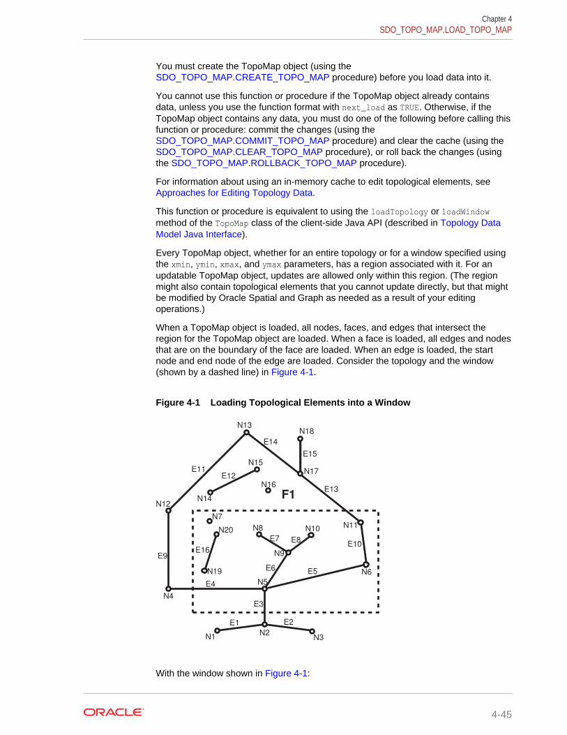
You must create the TopoMap object (using the SDO_TOPO_MAP.CREATE_TOPO_MAP procedure) before you load data into it.
You cannot use this function or procedure if the TopoMap object already containsdata, unless you use the function format with next_load as TRUE. Otherwise, if theTopoMap object contains any data, you must do one of the following before calling thisfunction or procedure: commit the changes (using the SDO_TOPO_MAP.COMMIT_TOPO_MAP procedure) and clear the cache (using the SDO_TOPO_MAP.CLEAR_TOPO_MAP procedure), or roll back the changes (usingthe SDO_TOPO_MAP.ROLLBACK_TOPO_MAP procedure).
For information about using an in-memory cache to edit topological elements, see Approaches for Editing Topology Data.
This function or procedure is equivalent to using the loadTopology or loadWindowmethod of the TopoMap class of the client-side Java API (described in Topology DataModel Java Interface).
Every TopoMap object, whether for an entire topology or for a window specified usingthe xmin, ymin, xmax, and ymax parameters, has a region associated with it. For anupdatable TopoMap object, updates are allowed only within this region. (The regionmight also contain topological elements that you cannot update directly, but that mightbe modified by Oracle Spatial and Graph as needed as a result of your editingoperations.)
When a TopoMap object is loaded, all nodes, faces, and edges that intersect theregion for the TopoMap object are loaded. When a face is loaded, all edges and nodesthat are on the boundary of the face are loaded. When an edge is loaded, the startnode and end node of the edge are loaded. Consider the topology and the window(shown by a dashed line) in Figure 4-1.
Figure 4-1 Loading Topological Elements into a Window
E1 E2
E3
E4
E5
N1N2
N3
N4
N5
N6
N7
N8
N9
N10N11
N12
N13
N14
N15
N16
N17
N18
N19
N20
E6
E7 E8
E9
E10
E11E12
E13
E14
E15
E16
F1
With the window shown in Figure 4-1:
Chapter 4SDO_TOPO_MAP.LOAD_TOPO_MAP
4-45
• Face F1 is loaded because it partially overlaps the window.
• The following edges are loaded: E3, E4, E5, E6, E7, E8, E9, E10, E11, E12, E13,E14, E16.
Edge E3 is loaded because it partially overlaps the window.
Edge E9 is loaded because it bounds a face (F1) that partially overlaps a window.
Edge E12 is loaded because it is an island edge in a face (F1) that partiallyoverlaps the window.
Edge E1 is not loaded because it is not associated with any face that interacts withthe window.
• The following nodes are loaded: N2, N5, N6, N7, N8, N9, N10, N11, N12, N16,N19, N20.
Non-isolated node N2 is loaded because edge E3 is loaded.
Non-isolated node N12 is loaded because edges E9 and E11 are loaded.
Isolated node N16 is loaded because it is an isolated (island) node inside a lockedface.
Examples
The following example loads all CITY_DATA topology elements into its associatedTopoMap object for editing and builds the in-memory R-tree indexes by default. Itreturns a result indicating that the operation was successful and that some topologicalelements were loaded into the cache. (The example refers to definitions and data from Topology Built from Topology Data.)
CALL SDO_TOPO_MAP.LOAD_TOPO_MAP('CITY_DATA_TOPOMAP', 'TRUE') INTO :res_varchar; Call completed. PRINT res_varchar; RES_VARCHAR--------------------------------------------------------------------------------TRUE
4.40 SDO_TOPO_MAP.MOVE_EDGEFormat
SDO_TOPO_MAP.MOVE_EDGE( topology IN VARCHAR2, edge_id IN NUMBER, s_node_id IN NUMBER, t_node_id IN NUMBER, edge_coords IN SDO_NUMBER_ARRAY);
or
SDO_TOPO_MAP.MOVE_EDGE( topology IN VARCHAR2, edge_id IN NUMBER, s_node_id IN NUMBER, t_node_id IN NUMBER, edge_coords IN SDO_NUMBER_ARRAY,
Chapter 4SDO_TOPO_MAP.MOVE_EDGE
4-46
moved_iso_nodes OUT SDO_NUMBER_ARRAY, moved_iso_edges OUT SDO_NUMBER_ARRAY, allow_iso_moves IN VARCHAR2);
Description
Moves a non-isolated edge.
Parameters
topologyName of the topology in which to move the edge, or null if you are using an updatableTopoMap object (see Specifying the Editing Approach with the Topology Parameter).Must not exceed 20 characters.
edge_idEdge ID of the edge to be moved.
edge_coordsAn array of coordinates of the resulting moved edge, from start point to end point.
s_node_idNode ID of the source node, which identifies the point (start node or end node of theedge) affected by the move, before the move occurs. For example, if the end point ofedge E19 is to be moved from node N17 to node N16, the s_node_id value is thenode ID number for node N17.
t_node_idNode ID of the target node, which identifies the point affected by the move, after themove occurs. For example, if the end point of edge E19 is to be moved from nodeN17 to node N16, the t_node_id value is the node ID number for node N16.
moved_iso_nodesOutput parameter in which, if the allow_iso_moves parameter value is TRUE, Spatialand Graph stores the node ID values of any isolated nodes that have moved to adifferent face as a result of this procedure. If the allow_iso_moves parameter value isFALSE, Spatial and Graph stores the node ID values of any isolated nodes that did notmove but that would have moved to a different face if the allow_iso_moves parametervalue had been TRUE.
moved_iso_edgesOutput parameter in which, if the allow_iso_moves parameter value is TRUE, Spatialand Graph stores the edge ID values of any isolated edges that have moved to adifferent face as a result of this procedure. If the allow_iso_moves parameter value isFALSE, Spatial and Graph stores the edge ID values of any isolated edges that did notmove but that would have moved to a different face if the allow_iso_moves parametervalue had been TRUE.
allow_iso_movesTRUE causes Spatial and Graph to allow an edge move operation that would causeany isolated nodes or edges to be in a different face, and to adjust the containing faceinformation for such isolated nodes and edges; FALSE causes Spatial and Graph notto allow an edge move operation that would cause any isolated nodes or edges to bein a different face.If you use the format that does not include the allow_iso_moves parameter, Spatialand Graph allows an edge move operation that would cause any isolated nodes or
Chapter 4SDO_TOPO_MAP.MOVE_EDGE
4-47
edges to be in a different face, and it adjusts the containing face information for suchisolated nodes and edges.
Usage Notes
For information about moving edges, see Moving an Edge.
This procedure is equivalent to using the moveEdge method of the TopoMap class of theclient-side Java API (described in Topology Data Model Java Interface).
Examples
The following example moves the edge with edge ID value 19, and it displays the edgecoordinates before and after the move. The edge move operation moves the end pointof the edge from the node with node ID value 17 to the node with node ID value 16.(The edge being moved is E19 in Figure 1-2 in Topology Data Model Concepts; andthe edge is being changed from going vertically up to node N17, to going diagonally upand left to node N16. The example refers to definitions and data from Topology Builtfrom Topology Data.)
-- Get coordinates of edge E19.SELECT SDO_TOPO_MAP.GET_EDGE_COORDS(null, 'CITY_DATA_TOPOMAP', 19) FROM DUAL; SDO_TOPO_MAP.GET_EDGE_COORDS(NULL,'CITY_DATA_TOPOMAP',19) --------------------------------------------------------------------------------SDO_NUMBER_ARRAY(21, 14, 21, 22) -- Move edge E19: from N14 -> N17 to N14 -> N16. The 3rd and 4th parameters-- identify N17 and N16.CALL SDO_TOPO_MAP.MOVE_EDGE(null, 19, 17, 16, SDO_NUMBER_ARRAY(21,14, 9,22)); Call completed. -- Get coordinates of edge E19 after the move.SELECT SDO_TOPO_MAP.GET_EDGE_COORDS(null, 'CITY_DATA_TOPOMAP', 19) FROM DUAL; SDO_TOPO_MAP.GET_EDGE_COORDS(NULL,'CITY_DATA_TOPOMAP',19) --------------------------------------------------------------------------------SDO_NUMBER_ARRAY(21, 14, 9, 22)
4.41 SDO_TOPO_MAP.MOVE_ISOLATED_NODEFormat
SDO_TOPO_MAP.MOVE_ISOLATED_NODE( topology IN VARCHAR2, node_id IN NUMBER, point IN SDO_GEOMETRY);
or
SDO_TOPO_MAP.MOVE_ISOLATED_NODE( topology IN VARCHAR2, node_id IN NUMBER, x IN NUMBER, y IN NUMBER);
Chapter 4SDO_TOPO_MAP.MOVE_ISOLATED_NODE
4-48

Description
Moves an isolated (island) node.
Parameters
topologyName of the topology in which to move the node, or null if you are using an updatableTopoMap object (see Specifying the Editing Approach with the Topology Parameter).Must not exceed 20 characters.
node_idNode ID of the node to be moved.
pointSDO_GEOMETRY object (point geometry) representing the location to which theisolated node is to be moved.
xX-axis value of the point representing the location to which the isolated node is to bemoved.
yY-axis value of the point representing the location to which the isolated node is to bemoved.
Usage Notes
For information about moving nodes, see Moving a Node.
The node must be moved to a location inside the face in which it is currently located.Otherwise, you must delete the node and re-create it.
This procedure is equivalent to using the moveIsolatedNode method of the TopoMapclass of the client-side Java API (described in Topology Data Model Java Interface).
Examples
The following example adds an isolated node and then moves it. (The example refersto definitions and data from Topology Built from Topology Data.)
CALL SDO_TOPO_MAP.ADD_ISOLATED_NODE(null, 2, SDO_GEOMETRY(2001, NULL, SDO_POINT_TYPE(22,38,NULL), NULL, NULL)) INTO :res_number; -- Move the just-added isolated node (from 20,38 to 22,39).CALL SDO_TOPO_MAP.MOVE_ISOLATED_NODE( null, :res_number, SDO_GEOMETRY(2001, NULL, SDO_POINT_TYPE(22,39,NULL), NULL, NULL));
4.42 SDO_TOPO_MAP.MOVE_NODEFormat
SDO_TOPO_MAP.MOVE_NODE( topology IN VARCHAR2, node_id IN NUMBER, edges_coords IN SDO_EDGE_ARRAY);
Chapter 4SDO_TOPO_MAP.MOVE_NODE
4-49

or
SDO_TOPO_MAP.MOVE_NODE( topology IN VARCHAR2, node_id IN NUMBER, edges_coords IN SDO_EDGE_ARRAY, moved_iso_nodes OUT SDO_NUMBER_ARRAY, moved_iso_edges OUT SDO_NUMBER_ARRAY, allow_iso_moves IN VARCHAR2);
Description
Moves a non-isolated node and its attached edges.
Parameters
topologyName of the topology in which to move the node, or null if you are using an updatableTopoMap object (see Specifying the Editing Approach with the Topology Parameter).Must not exceed 20 characters.
node_idNode ID of the node to be moved.
edges_coordsAn array of arrays, of type SDO_EDGE_ARRAY (described in SDO_EDGE_ARRAYand SDO_NUMBER_ARRAY Types). Each inner array consists of coordinates ofeach resulting attached edge, from start point to end point. The outer array consists ofthe attached edge arrays, starting with the start edge of the node to be moved andproceeding in clockwise order (with the sequence of the edges as would be obtainedin a call to the SDO_TOPO_MAP.GET_NODE_STAR function).The array for each edge must include the start and end points. Any loops that connecttwice at the moved node must be specified twice in the array.
moved_iso_nodesOutput parameter in which, if the allow_iso_moves parameter value is TRUE, Spatialand Graph stores the node ID values of any isolated nodes that have moved to adifferent face as a result of this procedure. If the allow_iso_moves parameter value isFALSE, Spatial and Graph stores the node ID values of any isolated nodes that did notmove but that would have moved to a different face if the allow_iso_moves parametervalue had been TRUE.
moved_iso_edgesOutput parameter in which, if the allow_iso_moves parameter value is TRUE, Spatialand Graph stores the edge ID values of any isolated edges that have moved to adifferent face as a result of this procedure. If the allow_iso_moves parameter value isFALSE, Spatial and Graph stores the edge ID values of any isolated edges that did notmove but that would have moved to a different face if the allow_iso_moves parametervalue had been TRUE.
allow_iso_movesTRUE causes Spatial and Graph to allow a node move operation that would cause anyisolated nodes or edges to be in a different face, and to adjust the containing faceinformation for such isolated nodes and edges; FALSE causes Spatial and Graph notto allow a node move operation that would cause any isolated nodes or edges to be ina different face.
Chapter 4SDO_TOPO_MAP.MOVE_NODE
4-50
If you use the format that does not include the allow_iso_moves parameter, Spatialand Graph allows a node move operation that would cause any isolated nodes oredges to be in a different face, and it adjusts the containing face information for suchisolated nodes and edges.
Usage Notes
For information about moving nodes, see Moving a Node.
This procedure is equivalent to using the moveNode method of the TopoMap class of theclient-side Java API (described in Topology Data Model Java Interface).
Examples
The following example moves node N3 and adjusts the coordinates of the onlyattached edge. (The example refers to definitions and data from Topology Built fromTopology Data.)
-- Move node N3 to right: from 25,35 to 26,35.-- E3 is changed from 25,30 -> 25,35 to 25,30 -> 26,35.CALL SDO_TOPO_MAP.MOVE_NODE(null, 3, SDO_EDGE_ARRAY(SDO_NUMBER_ARRAY(25,30, 26,35)));
4.43 SDO_TOPO_MAP.REMOVE_EDGEFormat
SDO_TOPO_MAP.REMOVE_EDGE( topology IN VARCHAR2, edge_id IN NUMBER);
Description
Removes an edge from a topology.
Parameters
topologyName of the topology from which to remove the edge, or null if you are using anupdatable TopoMap object (see Specifying the Editing Approach with the TopologyParameter). Must not exceed 20 characters.
edge_idEdge ID of the edge to be removed.
Usage Notes
If topology is not null, Spatial and Graph automatically updates the appropriate entriesin the <topology-name>_EDGE$ and <topology-name>_FACE$ tables. (If topology isnull, you can update these tables at any time by calling the SDO_TOPO_MAP.UPDATE_TOPO_MAP procedure.)
For information about removing an edge from a topology, see Removing an Edge.
Examples
The following example removes the edge with edge ID value 99 from the currentupdatable TopoMap object.
Chapter 4SDO_TOPO_MAP.REMOVE_EDGE
4-51
CALL SDO_TOPO_MAP.REMOVE_EDGE(null, 99);
4.44 SDO_TOPO_MAP.REMOVE_NODEFormat
SDO_TOPO_MAP.REMOVE_NODE( topology IN VARCHAR2, node_id IN NUMBER);
Description
Removes a node from a topology.
Parameters
topologyName of the topology from which to remove the node, or null if you are using anupdatable TopoMap object (see Specifying the Editing Approach with the TopologyParameter). Must not exceed 20 characters.
node_idNode ID of the node to be removed.
Usage Notes
If topology is not null, Spatial and Graph automatically updates the appropriate entriesin the <topology-name>_NODE$ and <topology-name>_EDGE$ tables, and in the<topology-name>_FACE$ table if necessary. (If topology is null, you can updatethese tables at any time by calling the SDO_TOPO_MAP.UPDATE_TOPO_MAPprocedure.)
For information about removing a node from a topology, see Removing a Node.
Examples
The following example removes the node with node ID value 500 from the currentupdatable TopoMap object.
CALL SDO_TOPO_MAP.REMOVE_NODE(null, 500);
4.45 SDO_TOPO_MAP.REMOVE_OBSOLETE_NODESFormat
SDO_TOPO_MAP.REMOVE_OBSOLETE_NODES( topology IN VARCHAR2);
Description
Removes obsolete nodes from a topology. (Obsolete nodes are explained in Removing Obsolete Nodes.)
Chapter 4SDO_TOPO_MAP.REMOVE_NODE
4-52
Parameters
topologyName of the topology from which to remove obsolete nodes, or null if you are usingan updatable TopoMap object (see Specifying the Editing Approach with the TopologyParameter). Must not exceed 20 characters.
Usage Notes
For information about removing obsolete nodes from a topology, see RemovingObsolete Nodes.
Examples
The following example removes all obsolete nodes from the current updatableTopoMap object.
CALL SDO_TOPO_MAP.REMOVE_OBSOLETE_NODES(null);
4.46 SDO_TOPO_MAP.ROLLBACK_TOPO_MAPFormat
SDO_TOPO_MAP.ROLLBACK_TOPO_MAP;
Description
Rolls back all changes to the database that were made using the current updatableTopoMap object, discards any changes in the object, clears the object's cachestructure, and makes the object read-only.
Parameters
None.
Usage Notes
Use this procedure when you are finished with a batch of edits to a topology and youwant to discard (that is, not commit) all changes to the database and in the cache.After the rollback operation completes, you cannot edit the TopoMap object. To makefurther edits to the topology, you can load the topology into the same TopoMap objectfor update (using the SDO_TOPO_MAP.LOAD_TOPO_MAP function or procedure), oryou can create a new TopoMap object (using the SDO_TOPO_MAP.CREATE_TOPO_MAP procedure) and load the topology into thatTopoMap object for update.
To commit all TopoMap object changes, use the SDO_TOPO_MAP.COMMIT_TOPO_MAP procedure.
For information about using an in-memory cache to edit topological elements, see Approaches for Editing Topology Data.
This procedure is equivalent to using the rollbackDB method of the TopoMap class ofthe client-side Java API (described in Topology Data Model Java Interface).
Chapter 4SDO_TOPO_MAP.ROLLBACK_TOPO_MAP
4-53
Examples
The following example rolls back from the database all changes associated with thecurrent updatable TopoMap object.
EXECUTE SDO_TOPO_MAP.ROLLBACK_TOPO_MAP;
4.47SDO_TOPO_MAP.SEARCH_EDGE_RTREE_TOPO_MAP
Format
SDO_TOPO_MAP.SEARCH_EDGE_RTREE_TOPO_MAP( topo_map IN VARCHAR2, xmin IN NUMBER, ymin IN NUMBER, xmax IN NUMBER, ymax IN NUMBER, capacity IN NUMBER ) RETURN SDO_NUMBER_ARRAY;
Description
Returns an array with the edge ID numbers of the edges that interact with a specifiedquery window. The query uses the edge R-tree built on the specified TopoMap object.
Parameters
topo_mapName of the TopoMap object. (TopoMap objects are explained in TopoMap Objects.)
xminLower-left X coordinate value for the query window.
yminLower-left Y coordinate value for the query window.
xmaxUpper-right X coordinate value for the query window.
ymaxUpper-right Y coordinate value for the query window.
capacityMaximum number of edge ID values to be returned. If you specify 0 or a negativenumber, 100 is used.
Usage Notes
This procedure is equivalent to using the searchEdgeRTree method of the TopoMapclass of the client-side Java API (described in Topology Data Model Java Interface).
Examples
The following example returns the edge ID numbers (up to 200) of edge that interactwith a query window whose lower-left corner is at (5,5) and upper-right corner is at
Chapter 4SDO_TOPO_MAP.SEARCH_EDGE_RTREE_TOPO_MAP
4-54
(30,40). (The example refers to definitions and data from Topology Built from TopologyData.)
SELECT SDO_TOPO_MAP.SEARCH_EDGE_RTREE_TOPO_MAP('CITY_DATA_TOPOMAP', - 5,5, 30,40, 200) FROM DUAL; SDO_TOPO_MAP.SEARCH_EDGE_RTREE_TOPO_MAP('CITY_DATA_TOPOMAP',5,5,30,40,200) --------------------------------------------------------------------------------SDO_NUMBER_ARRAY(12, 13, 22, 20, 9, 21, 19, 6, 10, 7, 26, 3, 1, 25, 2)
4.48SDO_TOPO_MAP.SEARCH_FACE_RTREE_TOPO_MAP
Format
SDO_TOPO_MAP.SEARCH_FACE_RTREE_TOPO_MAP( topo_map IN VARCHAR2, xmin IN NUMBER, ymin IN NUMBER, xmax IN NUMBER, ymax IN NUMBER, capacity IN NUMBER ) RETURN SDO_NUMBER_ARRAY;
Description
Returns an array with the face ID numbers of the faces that interact with a specifiedquery window. The query uses the face R-tree built on the specified TopoMap object.
Parameters
topo_mapName of the TopoMap object. (TopoMap objects are explained in TopoMap Objects.)
xminLower-left X coordinate value for the query window.
yminLower-left Y coordinate value for the query window.
xmaxUpper-right X coordinate value for the query window.
ymaxUpper-right Y coordinate value for the query window.
capacityMaximum number of face ID values to be returned. If you specify 0 or a negativenumber, 100 is used.
Usage Notes
This procedure is equivalent to using the searchFaceRTree method of the TopoMapclass of the client-side Java API (described in Topology Data Model Java Interface).
Chapter 4SDO_TOPO_MAP.SEARCH_FACE_RTREE_TOPO_MAP
4-55

Examples
The following example returns the face ID numbers (up to 200) of faces that interactwith a query window whose lower-left corner is at (5,5) and upper-right corner is at(30,40). (The example refers to definitions and data from Topology Built from TopologyData.)
SELECT SDO_TOPO_MAP.SEARCH_FACE_RTREE_TOPO_MAP('CITY_DATA_TOPOMAP', - 5,5, 30,40, 200) FROM DUAL; SDO_TOPO_MAP.SEARCH_FACE_RTREE_TOPO_MAP('CITY_DATA_TOPOMAP',5,5,30,40,200) --------------------------------------------------------------------------------SDO_NUMBER_ARRAY(6, 7, 3, 4, 9, 1, 2)
4.49 SDO_TOPO_MAP.SET_MAX_MEMORY_SIZEFormat
SDO_TOPO_MAP.SET_MAX_MEMORY_SIZE( maxsize IN NUMBER DEFAULT 268435456);
Description
Sets the Java maximum heap size for an application to run in an Oracle Java virtualmachine.
Parameters
maxsizeNumber of bytes for the Java maximum heap size. The default value is 268435456(256 MB).
Usage Notes
If you encounter the java.lang.OutOfMemoryError exception, you can use thisprocedure to increase the maximum heap size.
If you specify a value greater than the system limit, the system limit is used.
Examples
The following example sets the Java maximum heap size to 536870912 (512 MB).
EXECUTE SDO_TOPO_MAP.SET_MAX_MEMORY_SIZE(536870912);
4.50 SDO_TOPO_MAP.UPDATE_TOPO_MAPFormat
SDO_TOPO_MAP.UPDATE_TOPO_MAP;
Description
Updates the topology to reflect edits made to the current updatable TopoMap object.
Chapter 4SDO_TOPO_MAP.SET_MAX_MEMORY_SIZE
4-56

Parameters
None.
Usage Notes
Use this procedure to update the topology periodically during an editing session, asexplained in Process for Editing Using Cache Explicitly (PL/SQL API). Updates aremade, as needed, to the edge, face, and node information tables (described in Topology Data Model Tables). The TopoMap object remains open for further editingoperations. The updates are not actually committed to the database until you call the SDO_TOPO_MAP.COMMIT_TOPO_MAP procedure.
This procedure performs a level-0 validation of the TopoMap object before it updatesthe topology. (See the explanation of the level parameter for the SDO_TOPO_MAP.VALIDATE_TOPO_MAP function.)
If you caused in-memory R-tree indexes to be created when you loaded the TopoMapobject (by specifying or accepting the default value of TRUE for the build_indexesparameter with the SDO_TOPO_MAP.LOAD_TOPO_MAP function or procedure), youcan rebuild these indexes by using the SDO_TOPO_MAP.CREATE_EDGE_INDEXand SDO_TOPO_MAP.CREATE_FACE_INDEX procedures. For best indexperformance, these indexes should be rebuilt periodically when you are editing a largenumber of topological elements.
Contrast this procedure with the SDO_TOPO_MAP.CLEAR_TOPO_MAP procedure,which clears the cache associated with a specified TopoMap object and makes theobject read-only.
To commit all TopoMap object changes, use the SDO_TOPO_MAP.COMMIT_TOPO_MAP procedure.
For information about using an in-memory cache to edit topological elements, see Approaches for Editing Topology Data.
This procedure is equivalent to using the updateTopology method of the TopoMap classof the client-side Java API (described in Topology Data Model Java Interface).
Examples
The following example updates the topology associated with the current updatableTopoMap object to reflect changes made to that object.
EXECUTE SDO_TOPO_MAP.UPDATE_TOPO_MAP;
4.51 SDO_TOPO_MAP.VALIDATE_TOPO_MAPFormat
SDO_TOPO_MAP.VALIDATE_TOPO_MAP( topo_map IN VARCHAR2, level IN NUMBER DEFAULT 1 ) RETURN VARCHAR2;
Chapter 4SDO_TOPO_MAP.VALIDATE_TOPO_MAP
4-57
Description
Performs a first-order validation of a TopoMap object, and optionally (by default)checks the computational geometry also; returns the string TRUE if the structure of thetopological elements in TopoMap object is consistent, and raises an exception if thestructure of the topological elements in TopoMap object is not consistent.
Parameters
topo_mapName of the TopoMap object. (TopoMap objects are explained in TopoMap Objects.)
levelA value of 0 checks for the following conditions as part of a first-order validation:
• All faces are closed, and none have infinite loops.
• All previous and next edge pointers are consistent.
• All edges meet at nodes.
• Each island node is associated with a face.
• All edges on a face boundary are associated with the face.
A value of 1 (the default) checks for all conditions associated with a value of 0, plusthe following conditions related to computational geometry:
• Each island is inside the boundary of its associated face.
• No edge intersects itself or another edge.
• Start and end coordinates of edges match coordinates of nodes.
• Node stars are properly ordered geometrically.
Usage Notes
This function checks the consistency of all pointer relationships among edges, nodes,and faces. You can use this function to validate an updatable TopoMap object beforeyou update the topology (using the SDO_TOPO_MAP.UPDATE_TOPO_MAPprocedure) or to validate a read-only TopoMap object before issuing queries.
This function uses a tolerance value of 10E-15 for its internal computations, asexplained in Tolerance in the Topology Data Model.
This function is equivalent to using the validateCache method of the TopoMap class ofthe client-side Java API (described in Topology Data Model Java Interface).
Examples
The following example validates the topology in the TopoMap object namedCITY_DATA_TOPOMAP, and it returns a result indicating that the topology is valid. (Theexample refers to definitions and data from Topology Built from Topology Data.)
CALL SDO_TOPO_MAP.VALIDATE_TOPO_MAP('CITY_DATA_TOPOMAP') INTO :res_varchar; Call completed. PRINT res_varchar; RES_VARCHAR
Chapter 4SDO_TOPO_MAP.VALIDATE_TOPO_MAP
4-58
--------------------------------------------------------------------------------TRUE
4.52 SDO_TOPO_MAP.VALIDATE_TOPOLOGYFormat
SDO_TOPO_MAP.VALIDATE_TOPOLOGY( topology IN VARCHAR2, ) RETURN VARCHAR2;
or
SDO_TOPO_MAP.VALIDATE_TOPOLOGY( topology IN VARCHAR2, prevent_updates IN VARCHAR2, level IN NUMBER DEFAULT 1 ) RETURN VARCHAR2;
or
SDO_TOPO_MAP.VALIDATE_TOPOLOGY( topology IN VARCHAR2, xmin IN NUMBER, ymin IN NUMBER, xmax IN NUMBER, ymax IN NUMBER ) RETURN VARCHAR2;
or
SDO_TOPO_MAP.VALIDATE_TOPOLOGY( topology IN VARCHAR2, xmin IN NUMBER, ymin IN NUMBER, xmax IN NUMBER, ymax IN NUMBER ) RETURN VARCHAR2;
Description
Loads an entire topology or a window (rectangular portion) of a topology into aTopoMap object; returns the string TRUE if the structure of the topology is consistent,and raises an exception if the structure of the topology is not consistent.
Parameters
topologyName of the topology to be validated. Must not exceed 20 characters.
xminLower-left X coordinate value for the window (rectangular portion of the topology) tobe validated.
yminLower-left Y coordinate value for the window (rectangular portion of the topology) tobe validated.
Chapter 4SDO_TOPO_MAP.VALIDATE_TOPOLOGY
4-59
xmaxUpper-right X coordinate value for the window (rectangular portion of the topology) tobe validated.
ymaxUpper-right Y coordinate value for the window (rectangular portion of the topology) tobe validated.
prevent_updatesTRUE prevents other users from updating the topology while the validation is beingperformed; FALSE allows other users to update the topology while the validation isbeing performed. If you specify FALSE, any topology changes made by other userswhile the validation is being performed will not be considered by this function and willnot affect the result.
levelA value of 0 checks for the following conditions:
• All faces are closed, and none have infinite loops.
• All previous and next edge pointers are consistent.
• All edges meet at nodes.
• Each island node is associated with a face.
• All edges on a face boundary are associated with the face.
A value of 1 (the default) checks for all conditions associated with a value of 0, plusthe following conditions related to computational geometry:
• Each island is inside the boundary of its associated face.
• No edge intersects itself or another edge.
• Start and end coordinates of edges match coordinates of nodes.
• Node stars are properly ordered geometrically.
Usage Notes
This function implicitly creates a TopoMap object, and removes the object after thevalidation is complete. (TopoMap objects are described in TopoMap Objects.)
This function uses a tolerance value of 10E-15 for its internal computations, asexplained in Tolerance in the Topology Data Model.
Examples
The following example validates the topology named CITY_DATA, and it returns a resultindicating that the topology is valid. (The example refers to definitions and data from Topology Built from Topology Data.)
CALL SDO_TOPO_MAP.VALIDATE_TOPOLOGY('CITY_DATA') INTO :res_varchar; Call completed. PRINT res_varchar; RES_VARCHAR--------------------------------------------------------------------------------TRUE
Chapter 4SDO_TOPO_MAP.VALIDATE_TOPOLOGY
4-60

Part IINetwork Data Model
This part covers the network data model graph feature of Oracle Spatial and Graph.
This document has two main parts:
• Topology Data Model provides conceptual, usage, and reference informationabout the Topology Data Model feature of Oracle Spatial and Graph.
• Part II provides conceptual, usage, and reference information about the NetworkData Model Graph feature of Oracle Spatial and Graph.
Part II contains the following chapters:
• Network Data Model Graph OverviewThis chapter explains the concepts and operations related to the network datamodel for representing capabilities or objects that are modeled as nodes and links(vertices and edges) in a graph.
• SDO_NET Package SubprogramsThe MDSYS.SDO_NET package contains subprograms (functions andprocedures) for managing networks.
• SDO_NFE Package SubprogramsThe MDSYS.SDO_NFE package contains subprograms (functions andprocedures) for performing network feature editing.

5Network Data Model Graph Overview
This chapter explains the concepts and operations related to the network data modelfor representing capabilities or objects that are modeled as nodes and links (verticesand edges) in a graph.
This model is called the Oracle Spatial and Graph Network Data Model Graph feature,or simply Network Data Model Graph. This chapter assumes that you are familiar withthe main Oracle Spatial and Graph concepts, data types, and operations, asdocumented in Oracle Spatial and Graph Developer's Guide.
Although this chapter discusses some network-related terms as they relate to OracleSpatial and Graph, it assumes that you are familiar with basic network data modelingconcepts.
• Introduction to Network ModelingIn many applications, capabilities or objects are modeled as nodes and links in anetwork. The network model contains logical information such as connectivityrelationships among nodes and links, directions of links, and costs of nodes andlinks.
• Main Steps in Using the Network Data Model GraphThis topic summarizes the main steps for working with the Network Data ModelGraph feature in Oracle Spatial and Graph. It refers to important concepts,structures, and operations that are described in detail in other topics.
• Network Data Model Graph ConceptsA network is a type of mathematical graph that captures relationships betweenobjects using connectivity.
• Network ApplicationsNetworks are used in applications to find how different objects are connected toeach other.
• Network HierarchySome network applications require representations at different levels ofabstraction. For example, two major processes might be represented as nodeswith a link between them at the highest level of abstraction, and each majorprocess might have several subordinate processes that are represented as nodesand links at the next level down.
• Network User DataFor user data defined through the xxx_SDO_NETWORK_USER_DATA views, thedefault user data I/O implementation (LODUserDataIOSDO) is used to access theuser data during network analysis. However, some user data is not included in thenode or link table, and thus cannot be registered throughxxx_SDO_NETWORK_USER_DATA views.
• Feature ModelingYou can model objects of interest on the network as features.
5-1

• Feature Modeling Using Network Feature Editing (NFE)Network feature editing (NFE) lets you create and manage an NFE model. An NFEmodel extends the feature modeling capabilities by enabling you to visualize andmanipulate features using Java Swing components and a PL/SQL API.
• Network ConstraintsNetwork constraints are restrictions defined on network analysis computations.
• Network Analysis Using Load on Demand
• Network Data Model Graph TablesThe connectivity information for a spatial network is stored in two tables: a nodetable and a link table. In addition, path information can be stored in a path tableand a path-link table.
• Network Data Model Graph and Network Feature Editing (NFE) Model MetadataViewsTwo sets of network metadata views can be created for each schema (user):xxx_SDO_NETWORK_xxxxxx and xxx_SDO_NFE_MODEL_xxxxxx, where theinitial xxx can be USER or ALL. These views are created, as needed, by Spatialand Graph
• Network Data Model Graph Application Programming InterfaceThe Oracle Spatial and Graph Network Data Model Graph feature includes twoclient application programming interfaces (APIs): a PL/SQL interface provided bythe SDO_NET package and a Java interface.
• Cross-Schema Network AccessIf database users other than the network owner need to read a network intomemory, you need to do one of the following options.
• Network ExamplesThis topic presents several Network Data Model Graph examples.
• Network Data Model Graph Tutorial and Other ResourcesNetwork Data Model Graph learning resources are available.
• README File for Spatial and Graph and Related Features
5.1 Introduction to Network ModelingIn many applications, capabilities or objects are modeled as nodes and links in anetwork. The network model contains logical information such as connectivityrelationships among nodes and links, directions of links, and costs of nodes and links.
With logical network information, you can analyze a network and answer questions,many of them related to path computing and tracing. For example, for a biochemicalpathway, you can find all possible reaction paths between two chemical compounds;or for a road network, you can find the following information:
• What is the shortest (distance) or fastest (travel time) path between two cities?
• What is the closest hotel to a specific airport, and how can I get there?
In addition to logical network information, spatial information such as node locationsand link geometries can be associated with the network. This information can help youto model the logical information (such as the cost of a route, because its physicallength can be directly computed from its spatial representation).
The Spatial and Graph Network Data Model Graph feature can be used for large,complex networks. For example, Figure 5-1 shows San Francisco and links, which
Chapter 5Introduction to Network Modeling
5-2

have been defined using the Network Data Model Graph feature, displayed in a demoweb-based application for network analysis. (You can install this demo using the NDMtutorial described in Network Data Model Graph Tutorial and Other Resources.)
Figure 5-1 San Francisco Nodes and Links
The generic data model and network analysis capability can model and analyze manykinds of network applications in addition to traditional geographical informationsystems (GIS). For example, in biochemistry, applications may need to model reactionpathway networks for living organisms; and in the pharmaceutical industry,applications that model the drug discovery process may need to model protein-proteininteraction.
The network modeling capabilities of Spatial and Graph include schema objects andan application programming interface (API). The schema objects include metadata andnetwork tables. The API includes a server-side PL/SQL API (the SDO_NET package)for creating and managing networks in the database, and a middle-tier (or client-side)Java API for network editing and analysis.
5.2 Main Steps in Using the Network Data Model GraphThis topic summarizes the main steps for working with the Network Data Model Graphfeature in Oracle Spatial and Graph. It refers to important concepts, structures, andoperations that are described in detail in other topics.
There are two basic approaches to creating a network:
• Let Spatial and Graph perform most operations, using procedures with names inthe form CREATE_<network-type>_NETWORK.
Chapter 5Main Steps in Using the Network Data Model Graph
5-3

• Perform the operations yourself: create the necessary network tables and updatethe network metadata.
With each approach, you must insert the network data into the network tables. Youcan then use the Network Data Model Graph PL/SQL and Java applicationprogramming interfaces (APIs) to update the network and perform other operations.(The PL/SQL and Java APIs are described in Network Data Model Graph ApplicationProgramming Interface.)
• Letting Spatial Perform Most Operations
• Performing the Operations Yourself
5.2.1 Letting Spatial Perform Most OperationsTo create a network by letting Spatial and Graph perform most of the necessaryoperations, follow these steps:
1. Create the network using a procedure with a name in the formCREATE_<network-type>_NETWORK, where <network-type> reflects the type ofnetwork that you want to create:
• SDO_NET.CREATE_SDO_NETWORK for a spatial network with non-LRSSDO_GEOMETRY objects
• SDO_NET.CREATE_LRS_NETWORK for a spatial network with LRSSDO_GEOMETRY objects
• SDO_NET.CREATE_TOPO_NETWORK for a spatial network with topologygeometry (SDO_TOPO_GEOMETRY) objects
• SDO_NET.CREATE_LOGICAL_NETWORK for a logical network that doesnot contain spatial information
Each of these procedures creates the necessary Network Data Model Graphtables (described in Network Data Model Graph Tables) and inserts a row with theappropriate network metadata information into thexxx_SDO_NETWORK_METADATA views (described in xxx_SDO_NETWORK_METADATA Views).
Each procedure has two formats: one format creates all Network Data ModelGraph tables using default names for the tables and certain columns, and otherformat lets you specify names for the tables and certain columns. The defaultnames for the Network Data Model Graph tables are <network-name>_NODE$,<network-name>_LINK$, <network-name>_PATH$, and <network-name>_PLINK$. The default name for cost columns in the Network Data ModelGraph tables is COST, and the default name for geometry columns isGEOMETRY.
2. Insert data into the node and link tables, and if necessary into the path and path-link tables. (The node, link, path, and path-link tables are described in NetworkData Model Graph Tables.)
3. Validate the network, using the SDO_NET.VALIDATE_NETWORK function.
4. For a spatial (SDO or LRS) network, insert the appropriate information into theUSER_SDO_GEOM_METADATA view, and create spatial indexes on thegeometry columns.
Chapter 5Main Steps in Using the Network Data Model Graph
5-4

If you plan to use a view as a node, link, or path table, you must specify the viewname for the TABLE_NAME column value when you insert information about thenode, link, or path table in the USER_SDO_GEOM_METADATA view.
5.2.2 Performing the Operations YourselfTo create a network by performing the necessary operations yourself, follow thesesteps:
1. Create the node table, using the SDO_NET.CREATE_NODE_TABLE procedure.
2. Insert data into the node table.
3. Create the link table, using the SDO_NET.CREATE_LINK_TABLE procedure.
4. Insert data into the link table.
5. Optionally, create the path table, using the SDO_NET.CREATE_PATH_TABLEprocedure.
6. If you created the path table, create the path-link table, using the SDO_NET.CREATE_PATH_LINK_TABLE procedure.
7. If you created the path table and if you want to create paths, insert data into thetable.
8. If you inserted data into the path table, insert the appropriate rows into the path-link table.
9. Insert a row into the USER_SDO_NETWORK_METADATA view with informationabout the network. (The USER_SDO_NETWORK_METADATA view is describedin xxx_SDO_NETWORK_METADATA Views.)
If you plan to use a view as a node, link, path, or path-link table, you must specifythe view name for the relevant columns when you insert information about thenetwork in the USER_SDO_NETWORK_METADATA view.
10. For a spatial (SDO or LRS) network, insert the appropriate information into theUSER_SDO_GEOM_METADATA view, and create spatial indexes on thegeometry columns.
If you plan to use a view as a node, link, or path table, you must specify the viewname for the TABLE_NAME column value when you insert information about thenode, link, or path table in the USER_SDO_GEOM_METADATA view.
11. Validate the network, using the SDO_NET.VALIDATE_NETWORK function.
You can change the sequence of some of these steps. For example, you can createboth the node and link tables first, and then insert data into each one; and you caninsert the row into the USER_SDO_NETWORK_METADATA view before you createthe node and link tables.
5.3 Network Data Model Graph ConceptsA network is a type of mathematical graph that captures relationships between objectsusing connectivity.
The connectivity may or may not be based on spatial proximity. For example, if twotowns are on opposite sides of a lake, the shortest path based on spatial proximity (astraight line across the middle of the lake) is not relevant if you want to drive from one
Chapter 5Network Data Model Graph Concepts
5-5
town to the other. Instead, to find the shortest driving distance, you need connectivityinformation about roads and intersections and about the "cost" of individual links.
A network consists of a set of nodes and links. Each link (sometimes also called anedge or a segment) specifies two nodes.
A network can be directed (that is, by default, the start and end nodes determine linkdirection) or undirected (that is, links can be traversed in either direction).
The following are some key terms related to the Network Data Model Graph: feature
• A node, also called a vertex, is a point where links can join each other. An isolated node is a node that is not included in any links. (A non-isolated node willbecome isolated if all links that include that node are deleted.)
• A link represents a relationship between two nodes. Within a directed network,any link can be undirected (that is, able to be traversed either from the start nodeto the end node or from the end node to the start node) or directed (that is, able tobe traversed only from the start node to the end node). Within an undirectednetwork, all links are undirected.
• A network element is a node or a link.
• A path is an alternating sequence of nodes and links, beginning and ending withnodes, and usually with no nodes and links appearing more than once. (Repeatingnodes and links within a path are permitted, but are rare in most networkapplications.)
• A subpath is a partial path along a path, created either as a result of a networkanalysis operation or explicitly by a user. Subpaths are explained and illustrated in Subpaths.
• A logical network contains connectivity information but no geometric information.This is the model used for network analysis. A logical network can be treated as adirected graph or undirected graph, depending on the application.
• A spatial network contains both connectivity information and geometricinformation. In a spatial network, the nodes and links are SDO_GEOMETRYgeometry objects without LRS information (an SDO network) or with LRSinformation (an LRS network), or SDO_TOPO_GEOMETRY objects (a topologygeometry network).
In an LRS network, each node includes a geometry ID value and a measure value,and each link includes a geometry ID value and start and end measure values;and the geometry ID value in each case refers to an SDO_GEOMETRY objectwith LRS information. A spatial network can be directed or undirected, dependingon the application.
• A feature is an object of interest in a network application that is associated with anode or link. Features and feature layer types are explained in Features andFeature Layers
• Cost is a non-negative numeric attribute that can be associated with links ornodes for computing the minimum cost path, which is the path that has theminimum total cost from a start node to an end node. You can specify a single costfactor, such as driving time or driving distance for links, in the network metadata,and network analytical functions that examine cost will use this specified costfactor.
• Duration is a non-negative numeric attribute that can be associated with links ornodes to specify a duration value for the link or node. The duration value can
Chapter 5Network Data Model Graph Concepts
5-6

indicate a number of minutes or any other user-determined significance. You canspecify a single duration factor, such as driving time for links, in the networkmetadata; however, if you use duration instead of cost to indicate elapsed time,network analytical functions that examine cost will not consider the specifiedduration factor.
• State is a string attribute, either ACTIVE or INACTIVE, that is associated with linksor nodes to specify whether or not a link or node will be considered by networkanalysis functions. For example, if the state of a node is INACTIVE, any links fromor to that node are ignored in the computation of the shortest path between twonodes. The state is ACTIVE by default when a link or node is created, but you canset the state INACTIVE.
• Type is a string attribute that can be associated with links or nodes to specify auser-defined value for the type of a link or a node.
• Temporary links, nodes, and paths exist only in a network memory object, and arenot written to the database when the network memory object is written. Forexample, during a network analysis and editing session you might createtemporary nodes to represent street addresses for shortest-path computations, butnot save these temporary nodes when you save the results of editing operations.
• Reachable nodes are all nodes that can be reached from a given node.Reaching nodes are all nodes that can reach a given node.
• The degree of a node is the number of links to (that is, incident upon) the node.The in-degree is the number of inbound links, and the out-degree is the numberof outbound links.
• A connected component is a group of network nodes that are directly orindirectly connected. If node A can reach node B, they must belong to the sameconnected component. If two nodes are not connected, it is concluded that there isno possible path between them. This information can be used as a filter to avoidunnecessary path computations.
• A spanning tree of a connected graph is a tree (that is, a graph with no cycles)that connects all nodes of the graph. (The directions of links are ignored in aspanning tree.) The minimum cost spanning tree is the spanning tree thatconnects all nodes and has the minimum total cost.
• A partitioned network is a network that contains multiple partitions. Partitioning alarge network enables only the necessary partitions to be loaded on demand intomemory, thus providing better overall performance.
Network partitions are sub-networks, each covering a subset of nodes and links ofthe entire network. Network partitions are the basic processing units for load ondemand analysis. They are created by assigning every node in the network to onlyone partition ID. Network partition information is stored in a partition table.
• Load on demand (load on demand analysis) is an approach that divides largenetworks into manageable partitions and only loads needed partitions duringanalysis, thus removing memory limitation as a consideration and providing betteroverall performance.
• Partition BLOBs are binary representations for network partitions. They providefaster partition loading time. They are stored in a partition BLOB table.
• The load on demand partition cache is an in-memory placeholder for networkpartitions loaded into memory during network analysis. You can configure thepartition cache.
Chapter 5Network Data Model Graph Concepts
5-7
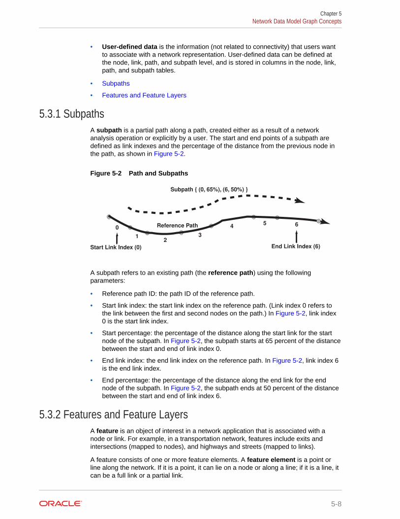
• User-defined data is the information (not related to connectivity) that users wantto associate with a network representation. User-defined data can be defined atthe node, link, path, and subpath level, and is stored in columns in the node, link,path, and subpath tables.
• Subpaths
• Features and Feature Layers
5.3.1 SubpathsA subpath is a partial path along a path, created either as a result of a networkanalysis operation or explicitly by a user. The start and end points of a subpath aredefined as link indexes and the percentage of the distance from the previous node inthe path, as shown in Figure 5-2.
Figure 5-2 Path and Subpaths
Start Link Index (0)
Subpath { (0, 65%), (6, 50%) }
Reference Path0 4 65
32
1
End Link Index (6)
A subpath refers to an existing path (the reference path) using the followingparameters:
• Reference path ID: the path ID of the reference path.
• Start link index: the start link index on the reference path. (Link index 0 refers tothe link between the first and second nodes on the path.) In Figure 5-2, link index0 is the start link index.
• Start percentage: the percentage of the distance along the start link for the startnode of the subpath. In Figure 5-2, the subpath starts at 65 percent of the distancebetween the start and end of link index 0.
• End link index: the end link index on the reference path. In Figure 5-2, link index 6is the end link index.
• End percentage: the percentage of the distance along the end link for the endnode of the subpath. In Figure 5-2, the subpath ends at 50 percent of the distancebetween the start and end of link index 6.
5.3.2 Features and Feature LayersA feature is an object of interest in a network application that is associated with anode or link. For example, in a transportation network, features include exits andintersections (mapped to nodes), and highways and streets (mapped to links).
A feature consists of one or more feature elements. A feature element is a point orline along the network. If it is a point, it can lie on a node or along a line; if it is a line, itcan be a full link or a partial link.
Chapter 5Network Data Model Graph Concepts
5-8
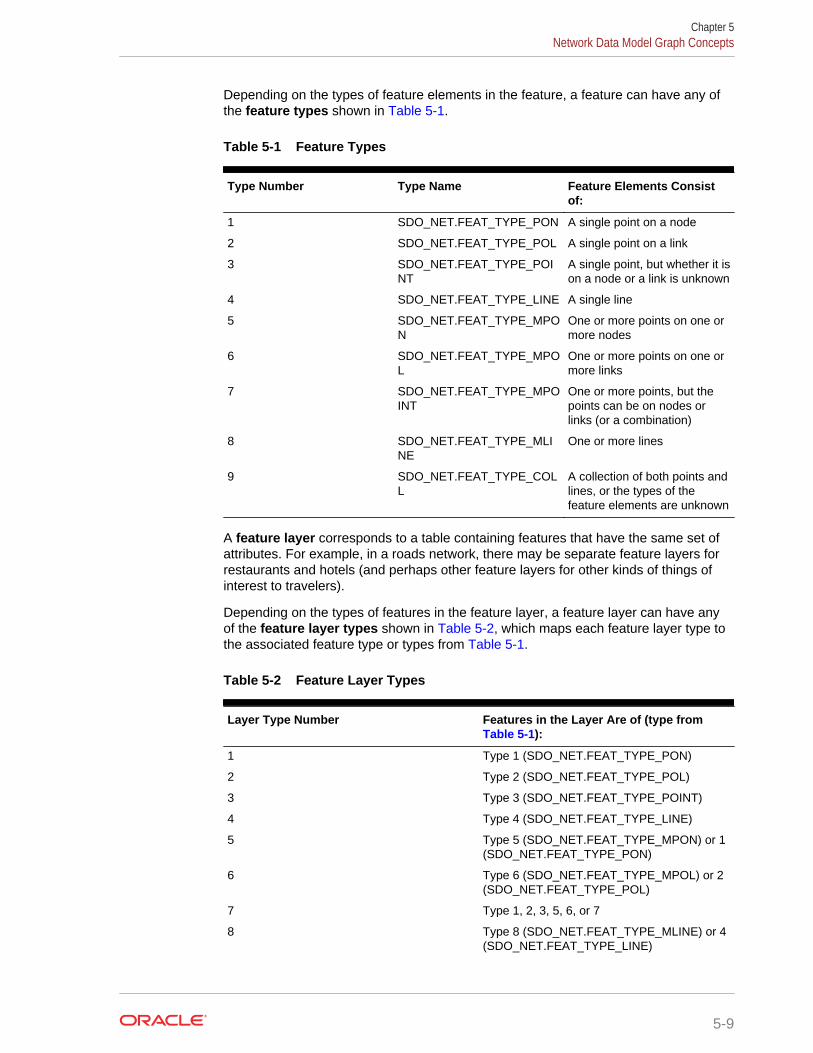
Depending on the types of feature elements in the feature, a feature can have any ofthe feature types shown in Table 5-1.
Table 5-1 Feature Types
Type Number Type Name Feature Elements Consistof:
1 SDO_NET.FEAT_TYPE_PON A single point on a node
2 SDO_NET.FEAT_TYPE_POL A single point on a link
3 SDO_NET.FEAT_TYPE_POINT
A single point, but whether it ison a node or a link is unknown
4 SDO_NET.FEAT_TYPE_LINE A single line
5 SDO_NET.FEAT_TYPE_MPON
One or more points on one ormore nodes
6 SDO_NET.FEAT_TYPE_MPOL
One or more points on one ormore links
7 SDO_NET.FEAT_TYPE_MPOINT
One or more points, but thepoints can be on nodes orlinks (or a combination)
8 SDO_NET.FEAT_TYPE_MLINE
One or more lines
9 SDO_NET.FEAT_TYPE_COLL
A collection of both points andlines, or the types of thefeature elements are unknown
A feature layer corresponds to a table containing features that have the same set ofattributes. For example, in a roads network, there may be separate feature layers forrestaurants and hotels (and perhaps other feature layers for other kinds of things ofinterest to travelers).
Depending on the types of features in the feature layer, a feature layer can have anyof the feature layer types shown in Table 5-2, which maps each feature layer type tothe associated feature type or types from Table 5-1.
Table 5-2 Feature Layer Types
Layer Type Number Features in the Layer Are of (type from Table 5-1):
1 Type 1 (SDO_NET.FEAT_TYPE_PON)
2 Type 2 (SDO_NET.FEAT_TYPE_POL)
3 Type 3 (SDO_NET.FEAT_TYPE_POINT)
4 Type 4 (SDO_NET.FEAT_TYPE_LINE)
5 Type 5 (SDO_NET.FEAT_TYPE_MPON) or 1(SDO_NET.FEAT_TYPE_PON)
6 Type 6 (SDO_NET.FEAT_TYPE_MPOL) or 2(SDO_NET.FEAT_TYPE_POL)
7 Type 1, 2, 3, 5, 6, or 7
8 Type 8 (SDO_NET.FEAT_TYPE_MLINE) or 4(SDO_NET.FEAT_TYPE_LINE)
Chapter 5Network Data Model Graph Concepts
5-9

Table 5-2 (Cont.) Feature Layer Types
Layer Type Number Features in the Layer Are of (type from Table 5-1):
9 Potentially a mixture of any number of featuretypes
A parent feature consists of features from one or more feature layers. For example, inan electrical network, substation is a parent feature for the feature layers for all itsassociated parts, such as joints, switches, and cables.
Features and feature layers can be edited and displayed using the NFE API. This APImakes it easier to model certain types of networks, such as electrical, gas, and waterutilities.
See Also:
• Feature Modeling Using Network Feature Editing (NFE)
5.4 Network ApplicationsNetworks are used in applications to find how different objects are connected to eachother.
The connectivity is often expressed in terms of adjacency and path relationships. Twonodes are adjacent if they are connected by a link. There are often several pathsbetween any two given nodes, and you may want to find the path with the minimumcost.
This topic describes some typical examples of different kinds of network applications.
• Road Network Example
• Subway (Train) Network Example
• Multimodal Network and Temporal Examples
• Utility Network Example
• Biochemical Network Example
5.4.1 Road Network ExampleIn a typical road network, the intersections of roads are nodes and the road segmentsbetween two intersections are links. The spatial representation of a road is notinherently related to the nodes and links in the network. For example, a shape point inthe spatial representation of a road (reflecting a sharp turn in the road) is not a node inthe network if that shape point is not associated with an intersection; and a singlespatial object may make up several links in a network (such as a straight segmentintersected by three crossing roads). An important operation with a road network is tofind the path from a start point to an end point, minimizing either the travel time or
Chapter 5Network Applications
5-10
distance. There may be additional constraints on the path computation, such as havingthe path go through a particular landmark or avoid a particular intersection.
5.4.2 Subway (Train) Network ExampleThe subway network of any major city is probably best modeled as a logical network,assuming that precise spatial representation of the stops and track lines isunimportant. In such a network, all stops on the system constitute the nodes of thenetwork, and a link is the connection between two stops if a train travels directlybetween these two stops. Important operations with a train network include finding allstations that can be reached from a specified station, finding the number of stopsbetween two specified stations, and finding the travel time between two stations.
5.4.3 Multimodal Network and Temporal ExamplesMultimodal networks are networks that consist of multiple modes, such as a networkconsisting of driving and walking routes. They are usually modeled as individualnetworks (of the specific mode) and are treated as an aggregate network so thatroutes of single mode as well as multiple modes can be represented and computed. Ingeneral, multimodal networks are "connected" by schedules of different modes, and insuch cases they are also temporal networks. An example is to compute an itinerarywith walking to nearest bus stop, taking the fastest bus route, getting off at the stopthat is closest to the destination, then walking to your destination. You could also addmodes like driving or flight to be taken into consideration.
Temporal modeling and analysis adds a temporal (time) dimension to networkmodeling and analysis. The time factor provides cost and/or constraints on top of static(non-temporal) networks. An example is to consider traffic patterns (time-dependenttravel time costs) instead of static travel-time costs.
Many metropolitan transportation networks consist of multiple modes such as buses,subways, and commuter rail lines, where transfers across modes are possible (forexample, from a bus to the subway). Each transportation mode has a componentnetwork within the larger transportation network. The component networks can bemodeled using nodes and links, and the transfers across modes can be modeled aslinks that connect the stops where transfers are possible.
An important feature of such multimodal transportation networks is their schedule-based operation. When performing common network operations such as computingthe fastest route from a start point to an end point, the schedule information andpossible transfers across modes must be considered. The schedule information atstops can be represented as user-defined data at the nodes representing these stops.Examples of operations that use schedule information in a multimodal network are (A)finding the fastest route (minimum travel time) from a start point to an end point for aspecified start time, and (B) finding the latest departure time at a start point to reach anend point by a specified arrival time.
5.4.4 Utility Network ExampleUtility networks, such as power line or cable networks, must often be configured tominimize the cost. An important operation with a utility network is to determine theconnections among nodes, using minimum cost spanning tree algorithms, to providethe required quality of service at the minimum cost. Another important operation isreachability analysis, so that, for example, if a station in a water network is shut down,you know which areas will be affected.
Chapter 5Network Applications
5-11
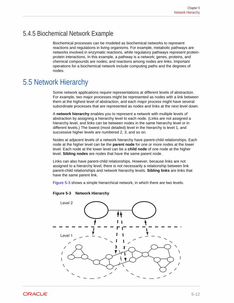
5.4.5 Biochemical Network ExampleBiochemical processes can be modeled as biochemical networks to representreactions and regulations in living organisms. For example, metabolic pathways arenetworks involved in enzymatic reactions, while regulatory pathways represent protein-protein interactions. In this example, a pathway is a network; genes, proteins, andchemical compounds are nodes; and reactions among nodes are links. Importantoperations for a biochemical network include computing paths and the degrees ofnodes.
5.5 Network HierarchySome network applications require representations at different levels of abstraction.For example, two major processes might be represented as nodes with a link betweenthem at the highest level of abstraction, and each major process might have severalsubordinate processes that are represented as nodes and links at the next level down.
A network hierarchy enables you to represent a network with multiple levels ofabstraction by assigning a hierarchy level to each node. (Links are not assigned ahierarchy level, and links can be between nodes in the same hierarchy level or indifferent levels.) The lowest (most detailed) level in the hierarchy is level 1, andsuccessive higher levels are numbered 2, 3, and so on.
Nodes at adjacent levels of a network hierarchy have parent-child relationships. Eachnode at the higher level can be the parent node for one or more nodes at the lowerlevel. Each node at the lower level can be a child node of one node at the higherlevel. Sibling nodes are nodes that have the same parent node.
Links can also have parent-child relationships. However, because links are notassigned to a hierarchy level, there is not necessarily a relationship between linkparent-child relationships and network hierarchy levels. Sibling links are links thathave the same parent link.
Figure 5-3 shows a simple hierarchical network, in which there are two levels.
Figure 5-3 Network Hierarchy
Level 2
Level 1
Chapter 5Network Hierarchy
5-12

As shown in Figure 5-3:
• The top level (level 2) contains two nodes. Each node is the parent node ofseveral nodes in the bottom level. The link between the nodes in the top level isthe parent link of two links between nodes in the bottom level.
• The bottom level (level 1) shows the nodes that make up each node in the toplevel. It also shows the links between nodes that are child nodes of each parentnode in the top level, and two links between nodes that have different parentnodes.
• The links between nodes in the bottom level that have different parent nodes areshown with dark connecting lines. These links are child links of the single linkbetween the nodes in the top level in the hierarchy. (However, these two links inthe bottom level could also be defined as not being child links of any parent linkbetween nodes in a higher level.)
• The parent-child relationships between each parent node and link and its childnodes and links are shown with dashed lines with arrowheads at both ends.
Although it is not shown in Figure 5-3, links can cross hierarchy levels. For example, alink could be defined between a node in the top level and any node in the bottom level.In this case, there would not be a parent-child relationship between the links.
Given certain grouping of nodes in a network, a parent network can be defined. Thegroup IDs in the child network are used as node IDs in the parent network. Theaggregated links between groups in the child network represent the links in the parentnetwork, with arbitrary link IDs assigned.
A network can have multiple ways of grouping its nodes based on different criteria;therefore, it can have multiple parent networks. In addition, nodes in a parent networkcan be further grouped to form a higher-level parent network. For example, in a socialnetwork, members can be grouped by city, profession, income, or other criteria.Members grouped by city, for example, can be further grouped into higher-levelcounty, state, or country networks.
The parent-child network relationship is defined through the CHILD_NETWORK andHIERARCHY_TABLE_NAME columns in the network metadata.
Note:
Do not confuse a hierarchical network with a multilevel network, which is anetwork with multiple link levels. A multilevel network does not necessarilyhave parent-child relationships between nodes; that is, a multilevel networkmay also be a hierarchical network or may also not be a hierarchicalnetwork. In a multilevel network, a higher-level network (such as level 2) isjust a subnetwork of a lower-level network (such as level 1), with link levelsgreater than or equal to the higher-level link.
5.6 Network User DataFor user data defined through the xxx_SDO_NETWORK_USER_DATA views, thedefault user data I/O implementation (LODUserDataIOSDO) is used to access the userdata during network analysis. However, some user data is not included in the node or
Chapter 5Network User Data
5-13
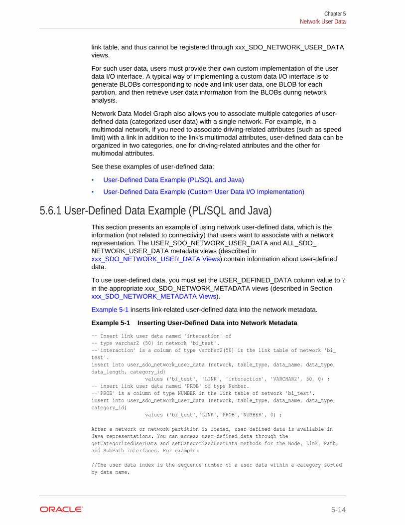
link table, and thus cannot be registered through xxx_SDO_NETWORK_USER_DATAviews.
For such user data, users must provide their own custom implementation of the userdata I/O interface. A typical way of implementing a custom data I/O interface is togenerate BLOBs corresponding to node and link user data, one BLOB for eachpartition, and then retrieve user data information from the BLOBs during networkanalysis.
Network Data Model Graph also allows you to associate multiple categories of user-defined data (categorized user data) with a single network. For example, in amultimodal network, if you need to associate driving-related attributes (such as speedlimit) with a link in addition to the link's multimodal attributes, user-defined data can beorganized in two categories, one for driving-related attributes and the other formultimodal attributes.
See these examples of user-defined data:
• User-Defined Data Example (PL/SQL and Java)
• User-Defined Data Example (Custom User Data I/O Implementation)
5.6.1 User-Defined Data Example (PL/SQL and Java)This section presents an example of using network user-defined data, which is theinformation (not related to connectivity) that users want to associate with a networkrepresentation. The USER_SDO_NETWORK_USER_DATA and ALL_SDO_NETWORK_USER_DATA metadata views (described in xxx_SDO_NETWORK_USER_DATA Views) contain information about user-defineddata.
To use user-defined data, you must set the USER_DEFINED_DATA column value to Yin the appropriate xxx_SDO_NETWORK_METADATA views (described in Section xxx_SDO_NETWORK_METADATA Views).
Example 5-1 inserts link-related user-defined data into the network metadata.
Example 5-1 Inserting User-Defined Data into Network Metadata
-- Insert link user data named 'interaction' of-- type varchar2 (50) in network 'bi_test'.--'interaction' is a column of type varchar2(50) in the link table of network 'bi_test'.insert into user_sdo_network_user_data (network, table_type, data_name, data_type, data_length, category_id) values ('bi_test', 'LINK', 'interaction', 'VARCHAR2', 50, 0) ;-- insert link user data named 'PROB' of type Number.--'PROB' is a column of type NUMBER in the link table of network 'bi_test'.insert into user_sdo_network_user_data (network, table_type, data_name, data_type, category_id) values ('bi_test','LINK','PROB','NUMBER', 0) ; After a network or network partition is loaded, user-defined data is available in Java representations. You can access user-defined data through the getCategorizedUserData and setCategorizedUserData methods for the Node, Link, Path, and SubPath interfaces. For example: //The user data index is the sequence number of a user data within a category sorted by data name.
Chapter 5Network User Data
5-14
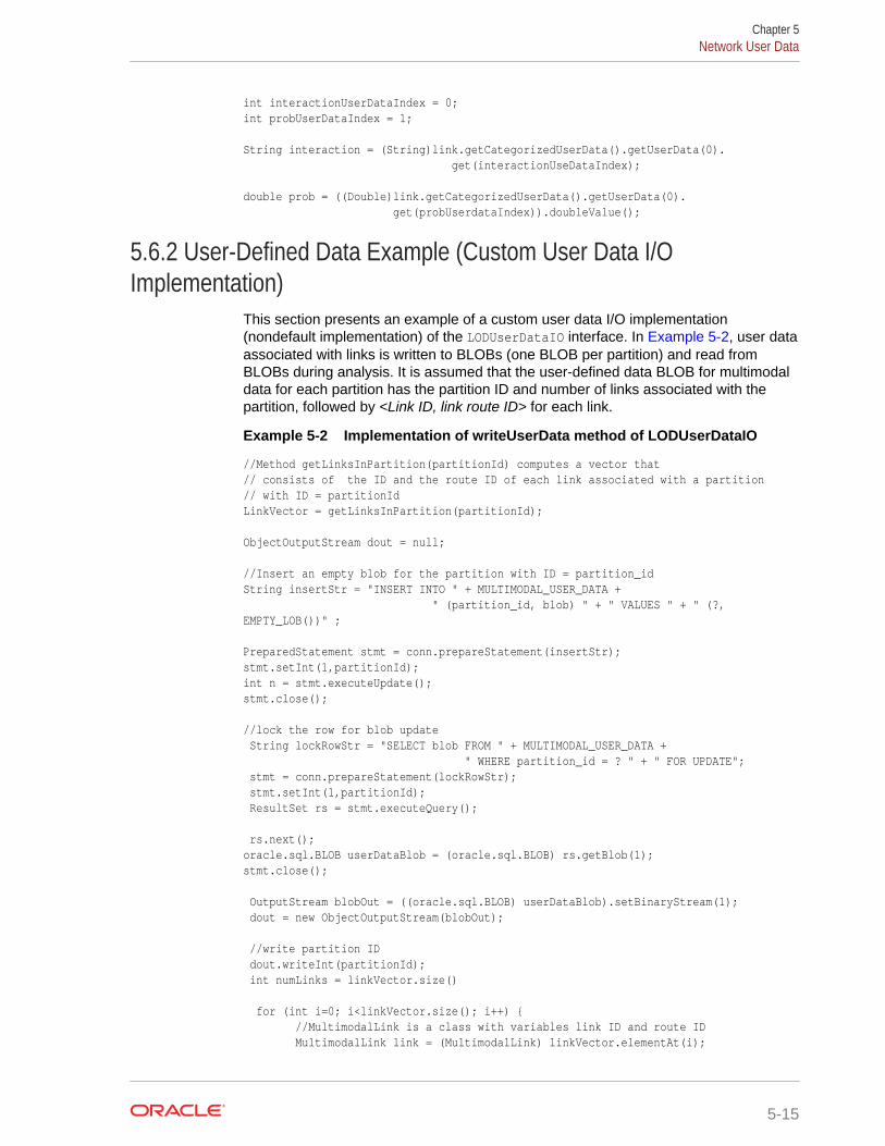
int interactionUserDataIndex = 0;int probUserDataIndex = 1; String interaction = (String)link.getCategorizedUserData().getUserData(0). get(interactionUseDataIndex); double prob = ((Double)link.getCategorizedUserData().getUserData(0). get(probUserdataIndex)).doubleValue();
5.6.2 User-Defined Data Example (Custom User Data I/OImplementation)
This section presents an example of a custom user data I/O implementation(nondefault implementation) of the LODUserDataIO interface. In Example 5-2, user dataassociated with links is written to BLOBs (one BLOB per partition) and read fromBLOBs during analysis. It is assumed that the user-defined data BLOB for multimodaldata for each partition has the partition ID and number of links associated with thepartition, followed by <Link ID, link route ID> for each link.
Example 5-2 Implementation of writeUserData method of LODUserDataIO
//Method getLinksInPartition(partitionId) computes a vector that// consists of the ID and the route ID of each link associated with a partition// with ID = partitionIdLinkVector = getLinksInPartition(partitionId);
ObjectOutputStream dout = null;
//Insert an empty blob for the partition with ID = partition_idString insertStr = "INSERT INTO " + MULTIMODAL_USER_DATA + " (partition_id, blob) " + " VALUES " + " (?, EMPTY_LOB())" ;
PreparedStatement stmt = conn.prepareStatement(insertStr);stmt.setInt(1,partitionId);int n = stmt.executeUpdate();stmt.close();
//lock the row for blob update String lockRowStr = "SELECT blob FROM " + MULTIMODAL_USER_DATA + " WHERE partition_id = ? " + " FOR UPDATE"; stmt = conn.prepareStatement(lockRowStr); stmt.setInt(1,partitionId); ResultSet rs = stmt.executeQuery();
rs.next();oracle.sql.BLOB userDataBlob = (oracle.sql.BLOB) rs.getBlob(1);stmt.close();
OutputStream blobOut = ((oracle.sql.BLOB) userDataBlob).setBinaryStream(1); dout = new ObjectOutputStream(blobOut);
//write partition ID dout.writeInt(partitionId); int numLinks = linkVector.size()
for (int i=0; i<linkVector.size(); i++) { //MultimodalLink is a class with variables link ID and route ID MultimodalLink link = (MultimodalLink) linkVector.elementAt(i);
Chapter 5Network User Data
5-15
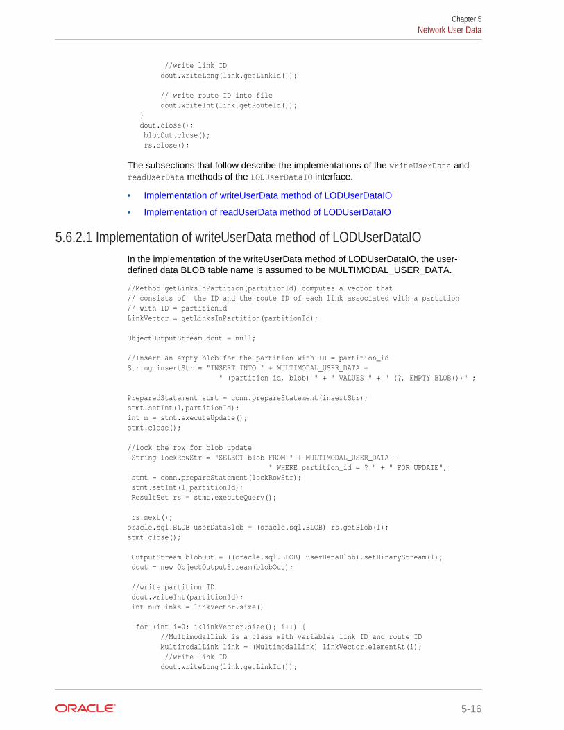
//write link ID dout.writeLong(link.getLinkId());
// write route ID into file dout.writeInt(link.getRouteId()); } dout.close(); blobOut.close(); rs.close();
The subsections that follow describe the implementations of the writeUserData andreadUserData methods of the LODUserDataIO interface.
• Implementation of writeUserData method of LODUserDataIO
• Implementation of readUserData method of LODUserDataIO
5.6.2.1 Implementation of writeUserData method of LODUserDataIOIn the implementation of the writeUserData method of LODUserDataIO, the user-defined data BLOB table name is assumed to be MULTIMODAL_USER_DATA.
//Method getLinksInPartition(partitionId) computes a vector that// consists of the ID and the route ID of each link associated with a partition// with ID = partitionIdLinkVector = getLinksInPartition(partitionId);
ObjectOutputStream dout = null;
//Insert an empty blob for the partition with ID = partition_idString insertStr = "INSERT INTO " + MULTIMODAL_USER_DATA + " (partition_id, blob) " + " VALUES " + " (?, EMPTY_BLOB())" ;
PreparedStatement stmt = conn.prepareStatement(insertStr);stmt.setInt(1,partitionId);int n = stmt.executeUpdate();stmt.close();
//lock the row for blob update String lockRowStr = "SELECT blob FROM " + MULTIMODAL_USER_DATA + " WHERE partition_id = ? " + " FOR UPDATE"; stmt = conn.prepareStatement(lockRowStr); stmt.setInt(1,partitionId); ResultSet rs = stmt.executeQuery();
rs.next();oracle.sql.BLOB userDataBlob = (oracle.sql.BLOB) rs.getBlob(1);stmt.close();
OutputStream blobOut = ((oracle.sql.BLOB) userDataBlob).setBinaryStream(1); dout = new ObjectOutputStream(blobOut);
//write partition ID dout.writeInt(partitionId); int numLinks = linkVector.size()
for (int i=0; i<linkVector.size(); i++) { //MultimodalLink is a class with variables link ID and route ID MultimodalLink link = (MultimodalLink) linkVector.elementAt(i); //write link ID dout.writeLong(link.getLinkId());
Chapter 5Network User Data
5-16
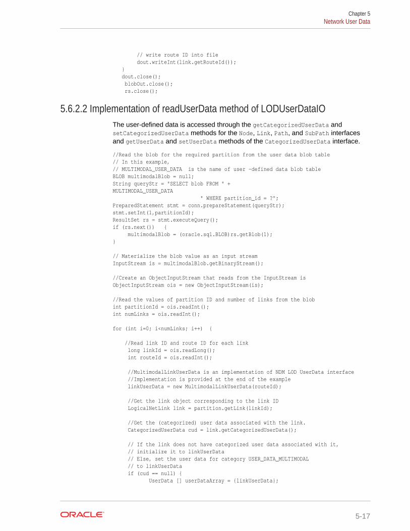
// write route ID into file dout.writeInt(link.getRouteId()); } dout.close(); blobOut.close(); rs.close();
5.6.2.2 Implementation of readUserData method of LODUserDataIOThe user-defined data is accessed through the getCategorizedUserData andsetCategorizedUserData methods for the Node, Link, Path, and SubPath interfacesand getUserData and setUserData methods of the CategorizedUserData interface.
//Read the blob for the required partition from the user data blob table// In this example,// MULTIMODAL_USER_DATA is the name of user –defined data blob tableBLOB multimodalBlob = null;String queryStr = "SELECT blob FROM " + MULTIMODAL_USER_DATA " WHERE partition_id = ?";PreparedStatement stmt = conn.prepareStatement(queryStr);stmt.setInt(1,partitionId);ResultSet rs = stmt.executeQuery();if (rs.next()) { multimodalBlob = (oracle.sql.BLOB)rs.getBlob(1);} // Materialize the blob value as an input stream InputStream is = multimodalBlob.getBinaryStream(); //Create an ObjectInputStream that reads from the InputStream isObjectInputStream ois = new ObjectInputStream(is); //Read the values of partition ID and number of links from the blobint partitionId = ois.readInt();int numLinks = ois.readInt(); for (int i=0; i<numLinks; i++) { //Read link ID and route ID for each link long linkId = ois.readLong(); int routeId = ois.readInt(); //MultimodalLinkUserData is an implementation of NDM LOD UserData interface //Implementation is provided at the end of the example linkUserData = new MultimodalLinkUserData(routeId); //Get the link object corresponding to the link ID LogicalNetLink link = partition.getLink(linkId); //Get the (categorized) user data associated with the link. CategorizedUserData cud = link.getCategorizedUserData(); // If the link does not have categorized user data associated with it, // initialize it to linkUserData // Else, set the user data for category USER_DATA_MULTIMODAL // to linkUserData if (cud == null) { UserData [] userDataArray = {linkUserData};
Chapter 5Network User Data
5-17
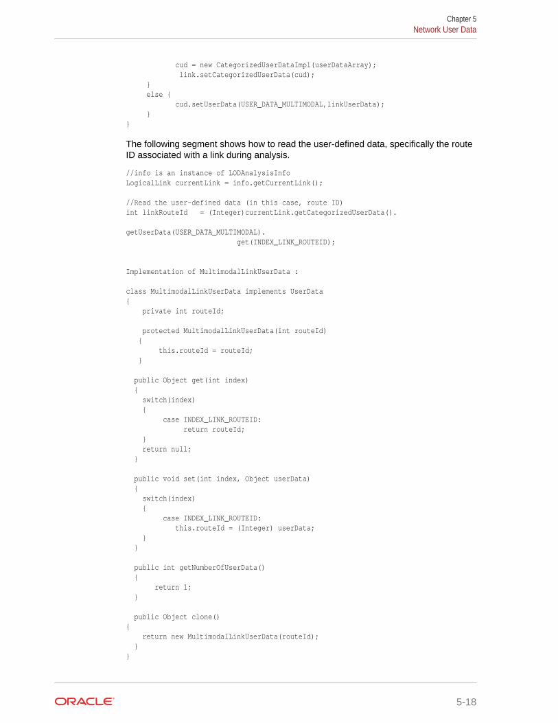
cud = new CategorizedUserDataImpl(userDataArray); link.setCategorizedUserData(cud); } else { cud.setUserData(USER_DATA_MULTIMODAL,linkUserData); }}
The following segment shows how to read the user-defined data, specifically the routeID associated with a link during analysis.
//info is an instance of LODAnalysisInfo LogicalLink currentLink = info.getCurrentLink(); //Read the user-defined data (in this case, route ID) int linkRouteId = (Integer)currentLink.getCategorizedUserData(). getUserData(USER_DATA_MULTIMODAL). get(INDEX_LINK_ROUTEID); Implementation of MultimodalLinkUserData : class MultimodalLinkUserData implements UserData{ private int routeId; protected MultimodalLinkUserData(int routeId) { this.routeId = routeId; } public Object get(int index) { switch(index) { case INDEX_LINK_ROUTEID: return routeId; } return null; } public void set(int index, Object userData) { switch(index) { case INDEX_LINK_ROUTEID: this.routeId = (Integer) userData; } } public int getNumberOfUserData() { return 1; } public Object clone(){ return new MultimodalLinkUserData(routeId); }}
Chapter 5Network User Data
5-18
5.7 Feature ModelingYou can model objects of interest on the network as features.
A feature consists of one or many feature elements. A feature element can be a point,a link, or a partial link along the network. You can define feature layers on top of anetwork. For example, restaurants and hotels can each be defined as a feature layeron a road network, and switches can be defined as a feature layer on an electricalnetwork.
The following are the typical steps for using feature modeling.
1. Create a feature layer.
For example, the points of interest (POIs) on a road network can be modeled asfeatures. Each type of POI (hotels, restaurants, hospitals, schools, and so on)corresponds to one feature layer. The following example adds a feature layer forhotels:
sdo_net.add_feature_layer( 'US_ROAD_NETWORK', --network name 'HOTEL', --feature layer name 2, --feature layer type: point on link 'HOTEL_TAB', --feature table or view name 'HOTEL_NET_REL', --relation table or view name null); --hierarchy table or view name
2. Register feature user data, if any application-specific feature attributes arepotentially useful in feature analysis.
Feature user data is registered by adding an entry in theXXX_SDO_NETWORK_USER_DATA view, just like registering the user data fornetwork nodes or links, except that the TABLE_TYPE column is set to the name ofthe feature table. The following example adds hotel name as user data for hotelfeatures:
INSERT INTO USER_SDO_NETWORK_USER_DATA( network, table_type, data_name, data_type, category_id)VALUES( 'US_ROAD_NETWORK', --network name 'HOTEL_TAB', --feature table or view name 'NAME', --user data name, i.e., name of the user data column 'VARCHAR2', --user data type 3); --user data category
3. Add, update, or delete features on the feature layer.
If the content of feature tables, feature element relationship table, and featurehierarchy table (all described in Feature Layer Tables) -- or any combination ofthese tables -- is managed by the data provider, then you can skip this step.Otherwise, you can call procedures in the SDO_NET package, such asADD_FEATURE, UPDATE_FEATURE, DELETE_FEATURES, to add, update ordelete features in a feature layer. (The SDO_NET subprograms are described in SDO_NET Package Subprograms.)
4. Perform feature analysis using NetworkAnalyst. The feature analysis functionsinclude:
• Shortest paths between features
• Nearest (reaching) features
Chapter 5Feature Modeling
5-19
• Within (reaching) cost features
• Data Types Used for Feature Modeling
5.7.1 Data Types Used for Feature ModelingThis section describes the following PL/SQL data types that are used for parametersand return values of some SDO_NET package subprograms related to featuremodeling:
• SDO_NET_FEAT_ELEM_ARRAY
• SDO_NET_FEAT_ELEM
• SDO_NET_LAYER_FEAT_ARRAY
• SDO_NET_LAYER_FEAT
• SDO_NETWORK_NVP_TAB
• SDO_NETWORK_NVP
SDO_NET_FEAT_ELEM_ARRAY is defined as VARRAY(1024) OFMDSYS.SDO_NET_FEAT_ELEM.
SDO_NET_FEAT_ELEM is defined as:
FEAT_ELEM_TYPE NUMBERNET_ELEM_ID NUMBERSTART_PERCENTAGE NUMBEREND_PERCENTAGE NUMBER
SDO_NET_LAYER_FEAT_ARRAY is defined as VARRAY(1024) OFMDSYS.SDO_NET_LAYER_FEAT.
SDO_NET_LAYER_FEAT is defined as:
FEATURE_LAYER_ID NUMBERFEATURE_ID NUMBER
SDO_NETWORK_NVP_TAB is defined as TABLE OF MDSYS.SDO_NETWORK_NVP.
SDO_NETWORK_NVP is defined as:
NAME VARCHAR2(128)VALUE VARCHAR2(1024)
5.8 Feature Modeling Using Network Feature Editing (NFE)Network feature editing (NFE) lets you create and manage an NFE model. An NFEmodel extends the feature modeling capabilities by enabling you to visualize andmanipulate features using Java Swing components and a PL/SQL API.
NFE lets you define features on the top of an existing network. For example,restaurants and hotels can be defined as features on the top of a road network. Youcan also define models that consist just of features (network elements are hidden fromyou), and where the connectivity can be restricted by rules. Such connectivityrestrictions are typically used in utility networks, such as electrical, water, or gasnetworks, to model the network devices and restrict the connectivity. One example ofusing connectivity restrictions is to avoid connections between high tension and lowtension devices in an electrical network
Chapter 5Feature Modeling Using Network Feature Editing (NFE)
5-20

NFE includes concepts such as feature classes and rules, which can be built into amodel. Metadata tables and views are automatically created and maintained when youcreate and work with an NFE model.
The minimum privileges required for using NFE features are CREATE TABLE,CREATEVIEW, CREATE SEQUENCE, and CREATE SESSION. These are in addition to any otherprivileges that the user might need to perform operations not specifically related toNFE.
• Creation Modes for NFE Models
• NFE Feature Classes
• NFE Rules
• Data Types Used for NFE Connectivity Rules
5.8.1 Creation Modes for NFE ModelsYou can create a network feature editing (NFE) model in one of two possible modes:from scratch and over an existing network model.
• From scratch: In this mode, a network is generated automatically when youcreate the NFE the model, and the network is assign to the model. You will workonly with features, and the underlying network elements will be hidden from you.This mode supports rules whose statements specify what kind of features (featureclasses) can be connected with each other kinds of features. One typical use ofthis mode is to model utility networks, such as electricity or water networks, whereyou want to restrict the connections among certain components in the network.
• Over an existing network model: In this mode, an existing network is used whenyou create the NFE model. The network is visible to you, and you can add featuresover the network elements. Rules are not supported in this mode.
The feature class relationship table contains information about the relationshipbetween features and feature classes, that is, which feature belongs to which featureclass.
5.8.2 NFE Feature ClassesA feature class describes a group of features based on attributes values, shape, andstyle. Each feature class belongs only to one feature layer, so the group of features inthe feature class also belongs to the same feature layer.
For example, an electrical network might include two feature layers: Transformers andConductors. Each of these feature layers might include two feature classes:
• The Transformers feature layer might include the HT Transformers (high tensiontransformers) and LT Transformers (low tension transformers), where transformerswithin each feature type have specified input and output voltages, and tensiontypes. Both feature types are associated with points (their shape). Each featuretype has a different associated icon for use in diagrams.
• The Conductors feature layer might include the HT Conductors (high tensionconductors) and LT Conductors (low tension conductors), where conductors withineach feature type have specified attribute values. Both feature types areassociated with lines (their shape). Each feature type has a different associatedicon for use in diagrams.
Chapter 5Feature Modeling Using Network Feature Editing (NFE)
5-21
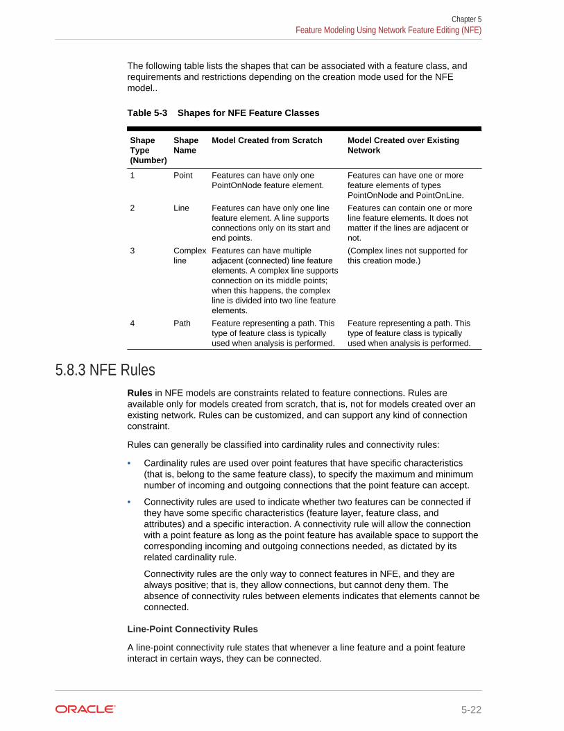
The following table lists the shapes that can be associated with a feature class, andrequirements and restrictions depending on the creation mode used for the NFEmodel..
Table 5-3 Shapes for NFE Feature Classes
ShapeType(Number)
ShapeName
Model Created from Scratch Model Created over ExistingNetwork
1 Point Features can have only onePointOnNode feature element.
Features can have one or morefeature elements of typesPointOnNode and PointOnLine.
2 Line Features can have only one linefeature element. A line supportsconnections only on its start andend points.
Features can contain one or moreline feature elements. It does notmatter if the lines are adjacent ornot.
3 Complexline
Features can have multipleadjacent (connected) line featureelements. A complex line supportsconnection on its middle points;when this happens, the complexline is divided into two line featureelements.
(Complex lines not supported forthis creation mode.)
4 Path Feature representing a path. Thistype of feature class is typicallyused when analysis is performed.
Feature representing a path. Thistype of feature class is typicallyused when analysis is performed.
5.8.3 NFE RulesRules in NFE models are constraints related to feature connections. Rules areavailable only for models created from scratch, that is, not for models created over anexisting network. Rules can be customized, and can support any kind of connectionconstraint.
Rules can generally be classified into cardinality rules and connectivity rules:
• Cardinality rules are used over point features that have specific characteristics(that is, belong to the same feature class), to specify the maximum and minimumnumber of incoming and outgoing connections that the point feature can accept.
• Connectivity rules are used to indicate whether two features can be connected ifthey have some specific characteristics (feature layer, feature class, andattributes) and a specific interaction. A connectivity rule will allow the connectionwith a point feature as long as the point feature has available space to support thecorresponding incoming and outgoing connections needed, as dictated by itsrelated cardinality rule.
Connectivity rules are the only way to connect features in NFE, and they arealways positive; that is, they allow connections, but cannot deny them. Theabsence of connectivity rules between elements indicates that elements cannot beconnected.
Line-Point Connectivity Rules
A line-point connectivity rule states that whenever a line feature and a point featureinteract in certain ways, they can be connected.
Chapter 5Feature Modeling Using Network Feature Editing (NFE)
5-22
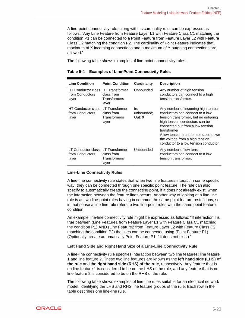
A line-point connectivity rule, along with its cardinality rule, can be expressed asfollows: “Any Line Feature from Feature Layer L1 with Feature Class C1 matching thecondition P1 can be connected to a Point Feature from Feature Layer L2 with FeatureClass C2 matching the condition P2. The cardinality of Point Feature indicates thatmaximum of X incoming connections and a maximum of Y outgoing connections areallowed.”
The following table shows examples of line-point connectivity rules.
Table 5-4 Examples of Line-Point Connectivity Rules
Line Condition Point Condition Cardinality Description
HT Conductor classfrom Conductorslayer
HT Transformerclass fromTransformerslayer
Unbounded Any number of high tensionconductors can connect to a hightension transformer.
HT Conductor classfrom Conductorslayer
LT Transformerclass fromTransformerslayer
In:unbounded;Out: 0
Any number of incoming high tensionconductors can connect to a lowtension transformer, but no outgoinghigh tension conductors can beconnected out from a low tensiontransformer.A low tension transformer steps downthe voltage from a high tensionconductor to a low tension conductor.
LT Conductor classfrom Conductorslayer
LT Transformerclass fromTransformerslayer
Unbounded Any number of low tensionconductors can connect to a lowtension transformer.
Line-Line Connectivity Rules
A line-line connectivity rule states that when two line features interact in some specificway, they can be connected through one specific point feature. The rule can alsospecify to automatically create the connecting point, if it does not already exist, whenthe interaction between the feature lines occurs. Another way of looking at a line-linerule is as two line-point rules having in common the same point feature restrictions, soin that sense a line-line rule refers to two line-point rules with the same point featurecondition.
An example line-line connectivity rule might be expressed as follows: “If interaction I istrue between (Line Feature1 from Feature Layer L1 with Feature Class C1 matchingthe condition P1) AND (Line Feature2 from Feature Layer L2 with Feature Class C2matching the condition P2) the lines can be connected using (Point Feature P1)(Optionally: create automatically Point Feature P1 if it does not exist).”
Left Hand Side and Right Hand Size of a Line-Line Connectivity Rule
A line-line connectivity rule specifies interaction between two line features: line feature1 and line feature 2. These two line features are known as the left hand side (LHS) ofthe rule and the right hand side (RHS) of the rule, respectively. Any feature that ison line feature 1 is considered to be on the LHS of the rule, and any feature that is online feature 2 is considered to be on the RHS of the rule.
The following table shows examples of line-line rules suitable for an electrical networkmodel, identifying the LHS and RHS line feature groups of the rule. Each row in thetable describes one line-line rule.
Chapter 5Feature Modeling Using Network Feature Editing (NFE)
5-23
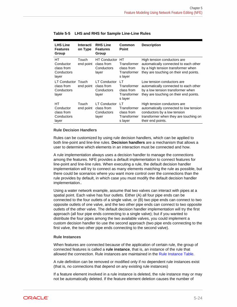
Table 5-5 LHS and RHS for Sample Line-Line Rules
LHS LineFeaturesGroup
Interaction Type
RHS LineFeaturesGroup
CommonPoint
Description
HTConductorclass fromConductorslayer
Touchend point
HT Conductorclass fromConductorslayer
HTTransformerclass fromTransformers layer
High tension conductors areautomatically connected to each otherby a high tension transformer whenthey are touching on their end points.
LT Conductorclass fromConductorslayer
Touchend point
LT Conductorclass fromConductorslayer
LTTransformerclass fromTransformers layer
Low tension conductors areautomatically connected to each otherby a low tension transformer whenthey are touching on their end points.
HTConductorclass fromConductorslayer
Touchend point
LT Conductorclass fromConductorslayer
LTTransformerclass fromTransformers layer
High tension conductors areautomatically connected to low tensionconductors by a low tensiontransformer when they are touching ontheir end points.
Rule Decision Handlers
Rules can be customized by using rule decision handlers, which can be applied toboth line-point and line-line rules. Decision handlers are a mechanism that allows auser to determine which elements in an interaction must be connected and how.
A rule implementation always uses a decision handler to manage the connectionsamong the features. NFE provides a default implementation to connect features forline-point and line-line rules. When executing a rule, the default decision handlerimplementation will try to connect as many elements matching the rule as possible, butthere could be scenarios where you want more control over the connections than therule provides by default, in which case you must modify the default decision handlerimplementation..
Using a water network example, assume that two valves can interact with pipes at aspatial point. Each valve has four outlets. Either (A) all four pipe ends can beconnected to the four outlets of a single valve, or (B) two pipe ends can connect to twoopposite outlets of one valve, and the two other pipe ends can connect to two oppositeoutlets of the other valve. The default decision handler implementation will try the firstapproach (all four pipe ends connecting to a single valve); but if you wanted todistribute the four pipes among the two available valves, you could implement acustom decision handler tio use the second approach (two pipe ends connecting to thefirst valve, the two other pipe ends connecting to the second valve).
Rule Instances
When features are connected because of the application of certain rule, the group ofconnected features is called a rule instance, that is, an instance of the rule thatallowed the connection. Rule instances are maintained in the Rule Instance Table.
A rule definition can be removed or modified only if no dependent rule instances exist(that is, no connections that depend on any existing rule instances)
If a feature element involved in a rule instance is deleted, the rule instance may or maynot be automatically deleted. If the feature element deletion causes the number of
Chapter 5Feature Modeling Using Network Feature Editing (NFE)
5-24
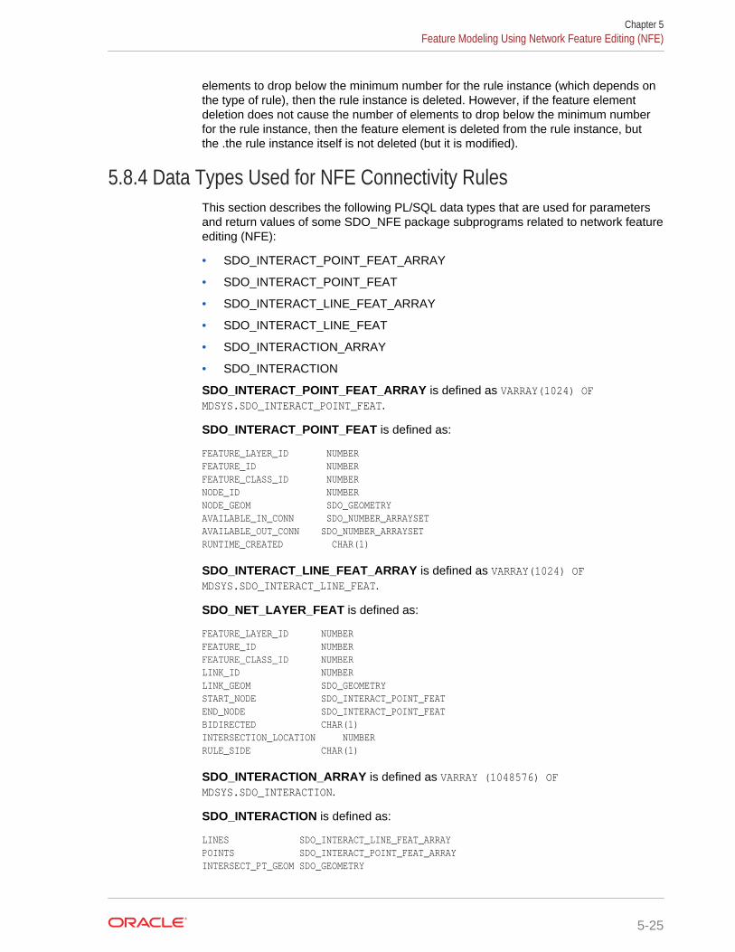
elements to drop below the minimum number for the rule instance (which depends onthe type of rule), then the rule instance is deleted. However, if the feature elementdeletion does not cause the number of elements to drop below the minimum numberfor the rule instance, then the feature element is deleted from the rule instance, butthe .the rule instance itself is not deleted (but it is modified).
5.8.4 Data Types Used for NFE Connectivity RulesThis section describes the following PL/SQL data types that are used for parametersand return values of some SDO_NFE package subprograms related to network featureediting (NFE):
• SDO_INTERACT_POINT_FEAT_ARRAY
• SDO_INTERACT_POINT_FEAT
• SDO_INTERACT_LINE_FEAT_ARRAY
• SDO_INTERACT_LINE_FEAT
• SDO_INTERACTION_ARRAY
• SDO_INTERACTION
SDO_INTERACT_POINT_FEAT_ARRAY is defined as VARRAY(1024) OFMDSYS.SDO_INTERACT_POINT_FEAT.
SDO_INTERACT_POINT_FEAT is defined as:
FEATURE_LAYER_ID NUMBER FEATURE_ID NUMBER FEATURE_CLASS_ID NUMBERNODE_ID NUMBER NODE_GEOM SDO_GEOMETRYAVAILABLE_IN_CONN SDO_NUMBER_ARRAYSETAVAILABLE_OUT_CONN SDO_NUMBER_ARRAYSETRUNTIME_CREATED CHAR(1)
SDO_INTERACT_LINE_FEAT_ARRAY is defined as VARRAY(1024) OFMDSYS.SDO_INTERACT_LINE_FEAT.
SDO_NET_LAYER_FEAT is defined as:
FEATURE_LAYER_ID NUMBERFEATURE_ID NUMBERFEATURE_CLASS_ID NUMBERLINK_ID NUMBERLINK_GEOM SDO_GEOMETRYSTART_NODE SDO_INTERACT_POINT_FEATEND_NODE SDO_INTERACT_POINT_FEATBIDIRECTED CHAR(1)INTERSECTION_LOCATION NUMBERRULE_SIDE CHAR(1)
SDO_INTERACTION_ARRAY is defined as VARRAY (1048576) OFMDSYS.SDO_INTERACTION.
SDO_INTERACTION is defined as:
LINES SDO_INTERACT_LINE_FEAT_ARRAYPOINTS SDO_INTERACT_POINT_FEAT_ARRAYINTERSECT_PT_GEOM SDO_GEOMETRY
Chapter 5Feature Modeling Using Network Feature Editing (NFE)
5-25

5.9 Network ConstraintsNetwork constraints are restrictions defined on network analysis computations.
For example, a network constraint might list a series of prohibited turns in a roadsnetwork due to one-way streets and "No Left Turn" signs, with each prohibited turnrepresented as a pair of links (a start link and an end link onto which a turn cannot bemade from the start link). As another example, a network constraint might require thatdriving routes must not include toll roads or must not include expressways.
To create a network constraint, you must create a Java class that implements theconstraint, and you must register the constraint by using the SDO_NET.REGISTER_CONSTRAINT procedure. To apply a network constraint to anetwork analysis operation, you must specify that constraint.
Examples of Java classes to implement network constraints are provided in theNetwork Data Model Graph demo files, which are described in Network Data ModelGraph Tutorial and Other Resources. For example, the ProhibitedTurns.java filecreates a network constraint that defines a series of prohibited turns, and it thenreturns the shortest path between two nodes, first without applying the constraint andthen applying the constraint.
5.10 Network Analysis Using Load on DemandLoad on demand means that during network analysis, a network partition is notloaded into memory until the analysis has reached this partition while exploring thenetwork.
With load on demand, Oracle Spatial and Graph performs most partitioning andloading operations automatically, and this usually results in more efficient memoryutilization with very large networks.
Load on demand analysis involves the following major steps: network creation,network partition, partition cache configuration, and network analysis.
1. Create the network, using one of the approaches described in Main Steps in Usingthe Network Data Model Graph.
2. Partition the network using the SDO_NET.SPATIAL_PARTITION procedure, asexplained in Partitioning a Network.
3. Optionally, generate partition BLOBs, as explained in Generating Partition BLOBs.
4. Configure the load on demand environment, including the partition cache, asexplained in Configuring the Partition Cache.
5. Analyze the network, as explained in Analyzing the Network.
Note:
Load on demand analysis also works with nonpartitioned networks bytreating the entire network as one partition. For a small network, there maybe no performance benefit in partitioning it, in which case you can skip thepartitioning but still use load on demand APIs.
Chapter 5Network Constraints
5-26

For examples of performing load on demand network analysis and configuring thepartition cache, see Partitioning and Load on Demand Analysis Examples (PL/SQL_XML_ and Java).
Additional examples of partitioning and load on demand analysis are included on theOracle Database Examples media (see Oracle Database Examples InstallationGuide). For more information about Network Data Model Graph example and demofiles, see Network Data Model Graph Tutorial and Other Resources.
• Partitioning a Network
• Generating Partition BLOBs
• Configuring the Partition Cache
• Analyzing the Network
• Using Link Levels for Priority Modeling
• Precomputed Analysis Results
5.10.1 Partitioning a NetworkYou can partition a network using the SDO_NET.SPATIAL_PARTITION procedure,specifying the maximum number of nodes in each partition. The partition result isstored in a partition table, which is automatically generated, and partition metadatainformation is inserted into the network metadata. (As an alternative to using theprocedure, you can partition a network by creating and populating a partition table.)You can use other SDO_NET subprograms to query the partitioning metadata.
A good partition strategy is to minimize the number of links between partitions, whichreduces the number of partitions that need to be loaded and the probable number oftimes that the same partitions need to be reloaded. Moreover, partitions that are toosmall require excessive loading and unloading of partitions during analysis.
The recommended maximum number of nodes per partition, assuming 1 GB ofmemory, is between 5,000 and 10,000. You can tune the number and see what is bestfor your applications, considering the available memory, type of analysis, and networksize. You should also consider configuring the partition caching size.
5.10.2 Generating Partition BLOBsTo enhance the performance of network loading, you can optionally store partitions asBLOBs in a network partition BLOB table. This information needs to be stored in thenetwork metadata view in order to take advantage of faster partition loading time. Notethat if a network or partition information is updated, the partition BLOBs need to beregenerated as well.
A partition BLOB is a binary stream of data containing the network partitioninformation, such as number of nodes, number of links, properties of each node,properties of each link, and so on. If a partition BLOB exists, Spatial and Graph uses itto read information during the load operation, rather than performing time-consumingdatabase queries.
To generate partition BLOBs, use the SDO_NET.GENERATE_PARTITION_BLOBSprocedure. The partition BLOBs and their metadata are stored in the Partition BLOBTable.
Chapter 5Network Analysis Using Load on Demand
5-27
5.10.3 Configuring the Partition CacheBefore you perform network analysis, you can configure the network partition cache tooptimize performance, by modifying an XML configuration file to override the defaultconfiguration. You can specify the following:
• Cache size: the maximum number of nodes in partition cache
• Partitions source: from network tables or partition BLOBs
• Resident partitions: IDs of partitions that will not be flushed out of the cache, butwill stay in memory once they are loaded
• Cache flushing policy: class name of the CachingHandler implementation
The default caching policy is LeastRecentlyUsed, which flushes out the oldestpartition out of memory when the cache is full. You can specify other cachingpolicies by implementing the CachingHandler interface.
A copy of the default load on demand configuration file is included in thesupplementary documentation, described in Network Data Model Graph Tutorial andOther Resources.
5.10.4 Analyzing the NetworkAfter you have created and partitioned the network, and optionally configured thepartition cache, you can issue analysis queries. Analysis results are returned in Javarepresentation or XML responses, depending on whether you used the Java or XMLAPI. For details, see the load on demand (LOD) Javadoc and XML schemas (the latterdescribed in Network Data Model Graph Tutorial and Other Resources).
You can write the analysis results to the database using the load on demand Java API.
5.10.5 Using Link Levels for Priority ModelingAlthough the load on demand approach reduces the effect of memory limitations inanalyzing large networks, analysis operations still can sometimes be very slow. Forexample, shortest path analysis of two nodes diagonally across the entire network islikely to require traversing almost every link in the network, and this will take asignificant amount of time for a network with more than, for example, two millionnodes.
To further reduce network analysis time, you can perform analysis on different linklevels. Link level is a positive integer assigned to a link indicating the level ofpreference of this link. The higher the link level, the higher the preference. Forexample, a road network may consist of two link levels, level 1 for local roads and level2 for highways. During network analysis, highways are preferred to local roads, andthe minimum link level is 1. (If no link level is assigned to a link, the default link level of1 is used for the link.)
Link levels have an implicit inheritance property, which means that a network at higherlink levels must be a subnetwork of a network at a lower link level. That is, link level 2is a subnetwork of link level 1, link level 3 is a subnetwork of link level 2, and so on.
You can specify a link level when you load a network or a partition, which causes linksat that level and higher levels to be loaded. Using the road network example, with linklevel 1 for local roads and link level 2 for highways, specifying link level 1 on a load
Chapter 5Network Analysis Using Load on Demand
5-28
operation loads links at link levels 1 and 2 (that is, local roads and highways), butspecifying link level 2 on a load operation loads only the highways links. If you wantedto perform analysis using only highways links, you could optimize the performance byspecifying link level 2 for the load operation.
5.10.6 Precomputed Analysis ResultsSome analysis operations, such as connected component analysis, can be timeconsuming. To improve runtime performance, you can call the SDO_NET.FIND_CONNECTED_COMPONENTS procedure, which computes theconnected components in the network and stores the results in the ConnectedComponent Table.
At runtime, before calling shortest path analysis or reachability analysis, you can checkwhether the nodes of interest belong to the same connected component by queryingthe connected component table. If precomputed component information does not exist,it may take a long time for shortest path and reachability analysis to discover that twonodes are, in fact, not connected.
5.11 Network Data Model Graph TablesThe connectivity information for a spatial network is stored in two tables: a node tableand a link table. In addition, path information can be stored in a path table and a path-link table.
You can have Spatial and Graph create these tables automatically when you createthe network using a CREATE_<network-type>_NETWORK procedure; or you cancreate these tables using the SDO_NET.CREATE_NODE_TABLE, SDO_NET.CREATE_LINK_TABLE, SDO_NET.CREATE_PATH_TABLE, and SDO_NET.CREATE_PATH_LINK_TABLE procedures.
These tables contain columns with predefined names, and you must not change any ofthe predefined column names; however, you can add columns to the tables by usingthe ALTER TABLE statement with the ADD COLUMN clause. For example, althougheach link and path table is created with a single COST column, you can createadditional columns and associate them with other comparable attributes. Thus, toassign a driving time, scenic appeal rating, and a danger rating to each link, you coulduse the COST column for driving time, add columns for SCENIC_APPEAL andDANGER to the link table, and populate all three columns with values to be interpretedby applications.
The following considerations apply to schema, table, and column names that arestored in any Oracle Spatial and Graph metadata views. For example, theseconsiderations apply to the names of node, link, path, and path-link tables, and to thenames of any columns in these tables that are stored in the network metadata viewsdescribed in Network Data Model Graph Metadata Views.
• The name must contain only letters, numbers, and underscores. For example, thename cannot contain a space ( ), an apostrophe ('), a quotation mark ("), or acomma (,).
• All letters in the names are converted to uppercase before the names are stored inmetadata views or before the tables are accessed. This conversion also applies toany schema name specified with the table name.
• Network Layer Tables
Chapter 5Network Data Model Graph Tables
5-29
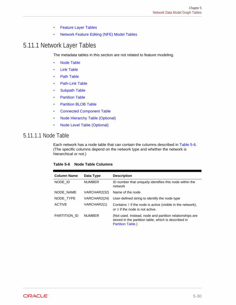
• Feature Layer Tables
• Network Feature Editing (NFE) Model Tables
5.11.1 Network Layer TablesThe metadata tables in this section are not related to feature modeling.
• Node Table
• Link Table
• Path Table
• Path-Link Table
• Subpath Table
• Partition Table
• Partition BLOB Table
• Connected Component Table
• Node Hierarchy Table (Optional)
• Node Level Table (Optional)
5.11.1.1 Node TableEach network has a node table that can contain the columns described in Table 5-6.(The specific columns depend on the network type and whether the network ishierarchical or not.)
Table 5-6 Node Table Columns
Column Name Data Type Description
NODE_ID NUMBER ID number that uniquely identifies this node within thenetwork
NODE_NAME VARCHAR2(32) Name of the node
NODE_TYPE VARCHAR2(24) User-defined string to identify the node type
ACTIVE VARCHAR2(1) Contains Y if the node is active (visible in the network),or N if the node is not active.
PARTITION_ID NUMBER (Not used. Instead, node and partition relationships arestored in the partition table, which is described in Partition Table.)
Chapter 5Network Data Model Graph Tables
5-30
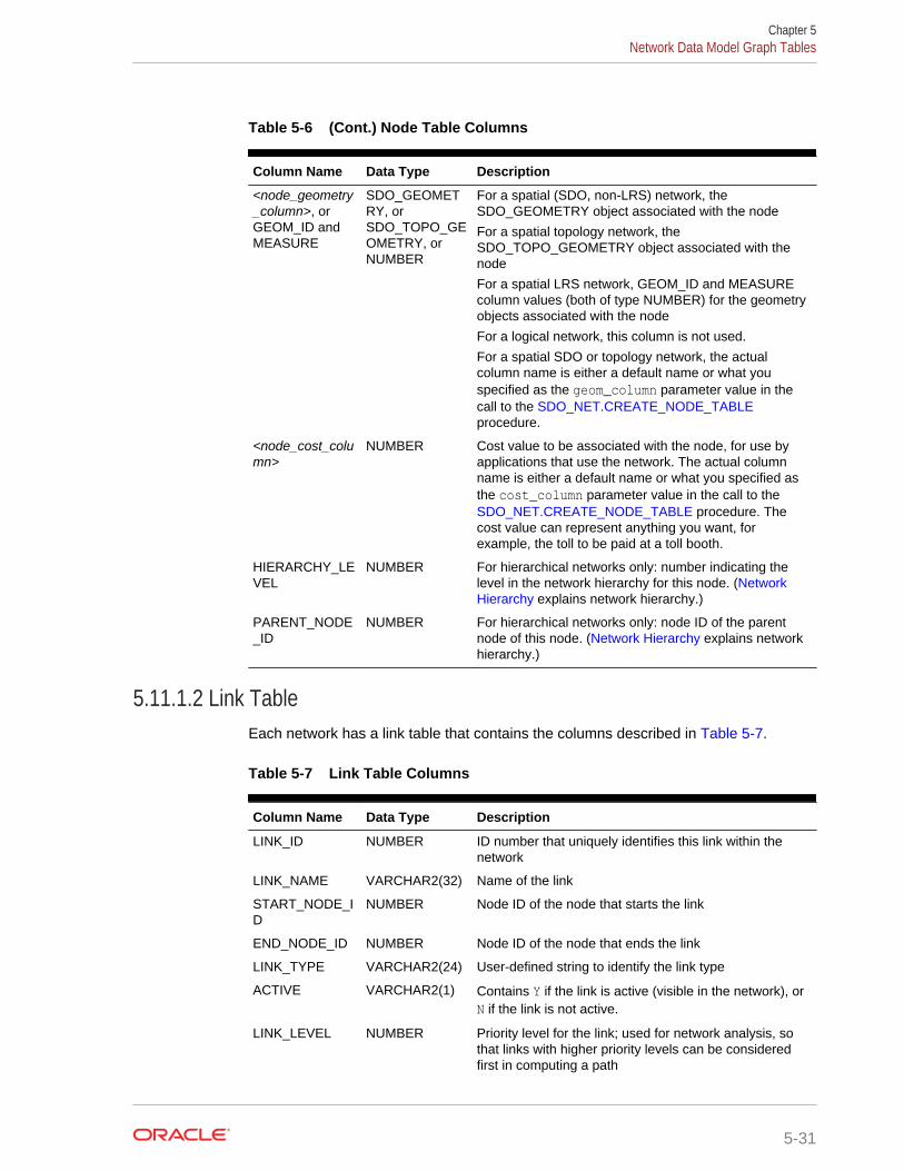
Table 5-6 (Cont.) Node Table Columns
Column Name Data Type Description
<node_geometry_column>, orGEOM_ID andMEASURE
SDO_GEOMETRY, orSDO_TOPO_GEOMETRY, orNUMBER
For a spatial (SDO, non-LRS) network, theSDO_GEOMETRY object associated with the node
For a spatial topology network, theSDO_TOPO_GEOMETRY object associated with thenode
For a spatial LRS network, GEOM_ID and MEASUREcolumn values (both of type NUMBER) for the geometryobjects associated with the node
For a logical network, this column is not used.
For a spatial SDO or topology network, the actualcolumn name is either a default name or what youspecified as the geom_column parameter value in thecall to the SDO_NET.CREATE_NODE_TABLEprocedure.
<node_cost_column>
NUMBER Cost value to be associated with the node, for use byapplications that use the network. The actual columnname is either a default name or what you specified asthe cost_column parameter value in the call to the SDO_NET.CREATE_NODE_TABLE procedure. Thecost value can represent anything you want, forexample, the toll to be paid at a toll booth.
HIERARCHY_LEVEL
NUMBER For hierarchical networks only: number indicating thelevel in the network hierarchy for this node. (NetworkHierarchy explains network hierarchy.)
PARENT_NODE_ID
NUMBER For hierarchical networks only: node ID of the parentnode of this node. (Network Hierarchy explains networkhierarchy.)
5.11.1.2 Link TableEach network has a link table that contains the columns described in Table 5-7.
Table 5-7 Link Table Columns
Column Name Data Type Description
LINK_ID NUMBER ID number that uniquely identifies this link within thenetwork
LINK_NAME VARCHAR2(32) Name of the link
START_NODE_ID
NUMBER Node ID of the node that starts the link
END_NODE_ID NUMBER Node ID of the node that ends the link
LINK_TYPE VARCHAR2(24) User-defined string to identify the link type
ACTIVE VARCHAR2(1) Contains Y if the link is active (visible in the network), orN if the link is not active.
LINK_LEVEL NUMBER Priority level for the link; used for network analysis, sothat links with higher priority levels can be consideredfirst in computing a path
Chapter 5Network Data Model Graph Tables
5-31
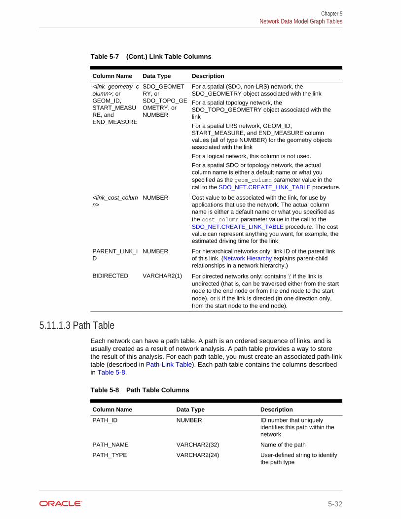
Table 5-7 (Cont.) Link Table Columns
Column Name Data Type Description
<link_geometry_column>; orGEOM_ID,START_MEASURE, andEND_MEASURE
SDO_GEOMETRY, orSDO_TOPO_GEOMETRY, orNUMBER
For a spatial (SDO, non-LRS) network, theSDO_GEOMETRY object associated with the link
For a spatial topology network, theSDO_TOPO_GEOMETRY object associated with thelink
For a spatial LRS network, GEOM_ID,START_MEASURE, and END_MEASURE columnvalues (all of type NUMBER) for the geometry objectsassociated with the link
For a logical network, this column is not used.
For a spatial SDO or topology network, the actualcolumn name is either a default name or what youspecified as the geom_column parameter value in thecall to the SDO_NET.CREATE_LINK_TABLE procedure.
<link_cost_column>
NUMBER Cost value to be associated with the link, for use byapplications that use the network. The actual columnname is either a default name or what you specified asthe cost_column parameter value in the call to the SDO_NET.CREATE_LINK_TABLE procedure. The costvalue can represent anything you want, for example, theestimated driving time for the link.
PARENT_LINK_ID
NUMBER For hierarchical networks only: link ID of the parent linkof this link. (Network Hierarchy explains parent-childrelationships in a network hierarchy.)
BIDIRECTED VARCHAR2(1) For directed networks only: contains Y if the link isundirected (that is, can be traversed either from the startnode to the end node or from the end node to the startnode), or N if the link is directed (in one direction only,from the start node to the end node).
5.11.1.3 Path TableEach network can have a path table. A path is an ordered sequence of links, and isusually created as a result of network analysis. A path table provides a way to storethe result of this analysis. For each path table, you must create an associated path-linktable (described in Path-Link Table). Each path table contains the columns describedin Table 5-8.
Table 5-8 Path Table Columns
Column Name Data Type Description
PATH_ID NUMBER ID number that uniquelyidentifies this path within thenetwork
PATH_NAME VARCHAR2(32) Name of the path
PATH_TYPE VARCHAR2(24) User-defined string to identifythe path type
Chapter 5Network Data Model Graph Tables
5-32

Table 5-8 (Cont.) Path Table Columns
Column Name Data Type Description
START_NODE_ID NUMBER Node ID of the node that startsthe first link in the path
END_NODE_ID NUMBER Node ID of the node that endsthe last link in the path
COST NUMBER Cost value to be associatedwith the path, for use byapplications that use thenetwork. The cost value canrepresent anything you want,for example, the estimateddriving time for the path.
SIMPLE VARCHAR2(1) Contains Y if the path is asimple path, or N if the path isa complex path. In a simplepath, the links form an orderedlist that can be traversed fromthe start node to the end nodewith each link visited once. Ina complex path, there aremultiple options for going fromthe start node to the end node.
<path_geometry_column> SDO_GEOMETRY For all network types exceptlogical, the geometry objectassociated with the path. Theactual column name is either adefault name or what youspecified as the geom_columnparameter value in the call tothe SDO_NET.CREATE_PATH_TABLE procedure.
For a logical network, thiscolumn is not used.
5.11.1.4 Path-Link TableFor each path table (described in Path Table), you must create a path-link table. Eachrow in the path-link table uniquely identifies a link within a path in a network; that is,each combination of PATH_ID, LINK_ID, and SEQ_NO values must be unique withinthe network. The order of rows in the path-link table is not significant. Each path-linktable contains the columns described in Table 5-9.
Table 5-9 Path-Link Table Columns
Column Name Data Type Description
PATH_ID NUMBER ID number of the path in thenetwork
LINK_ID NUMBER ID number of the link in thenetwork
Chapter 5Network Data Model Graph Tables
5-33
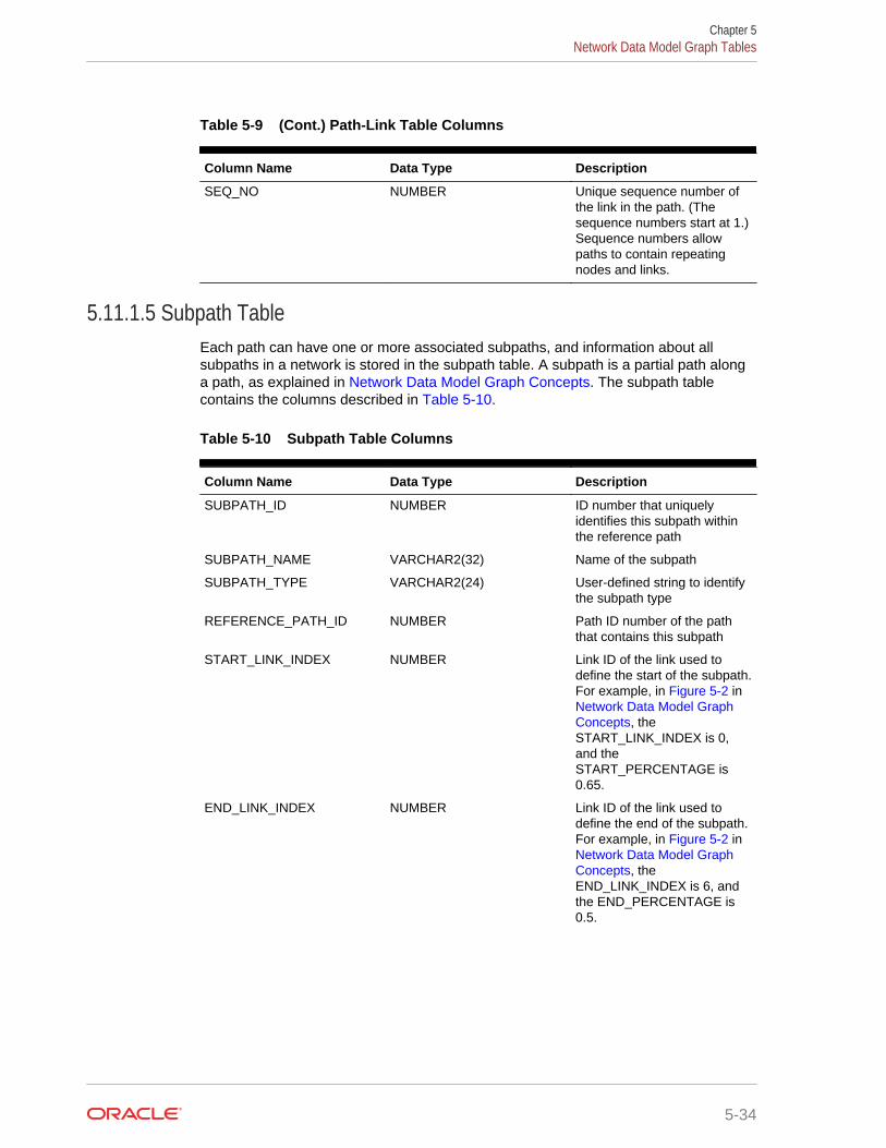
Table 5-9 (Cont.) Path-Link Table Columns
Column Name Data Type Description
SEQ_NO NUMBER Unique sequence number ofthe link in the path. (Thesequence numbers start at 1.)Sequence numbers allowpaths to contain repeatingnodes and links.
5.11.1.5 Subpath TableEach path can have one or more associated subpaths, and information about allsubpaths in a network is stored in the subpath table. A subpath is a partial path alonga path, as explained in Network Data Model Graph Concepts. The subpath tablecontains the columns described in Table 5-10.
Table 5-10 Subpath Table Columns
Column Name Data Type Description
SUBPATH_ID NUMBER ID number that uniquelyidentifies this subpath withinthe reference path
SUBPATH_NAME VARCHAR2(32) Name of the subpath
SUBPATH_TYPE VARCHAR2(24) User-defined string to identifythe subpath type
REFERENCE_PATH_ID NUMBER Path ID number of the paththat contains this subpath
START_LINK_INDEX NUMBER Link ID of the link used todefine the start of the subpath.For example, in Figure 5-2 in Network Data Model GraphConcepts, theSTART_LINK_INDEX is 0,and theSTART_PERCENTAGE is0.65.
END_LINK_INDEX NUMBER Link ID of the link used todefine the end of the subpath.For example, in Figure 5-2 in Network Data Model GraphConcepts, theEND_LINK_INDEX is 6, andthe END_PERCENTAGE is0.5.
Chapter 5Network Data Model Graph Tables
5-34
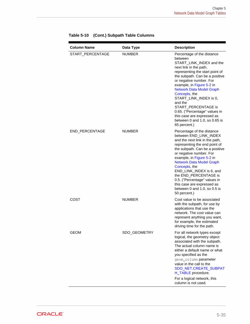
Table 5-10 (Cont.) Subpath Table Columns
Column Name Data Type Description
START_PERCENTAGE NUMBER Percentage of the distancebetweenSTART_LINK_INDEX and thenext link in the path,representing the start point ofthe subpath. Can be a positiveor negative number. Forexample, in Figure 5-2 in Network Data Model GraphConcepts, theSTART_LINK_INDEX is 0,and theSTART_PERCENTAGE is0.65. ("Percentage" values inthis case are expressed asbetween 0 and 1.0, so 0.65 is65 percent.)
END_PERCENTAGE NUMBER Percentage of the distancebetween END_LINK_INDEXand the next link in the path,representing the end point ofthe subpath. Can be a positiveor negative number. Forexample, in Figure 5-2 in Network Data Model GraphConcepts, theEND_LINK_INDEX is 6, andthe END_PERCENTAGE is0.5. ("Percentage" values inthis case are expressed asbetween 0 and 1.0, so 0.5 is50 percent.)
COST NUMBER Cost value to be associatedwith the subpath, for use byapplications that use thenetwork. The cost value canrepresent anything you want,for example, the estimateddriving time for the path.
GEOM SDO_GEOMETRY For all network types exceptlogical, the geometry objectassociated with the subpath.The actual column name iseither a default name or whatyou specified as thegeom_column parametervalue in the call to the SDO_NET.CREATE_SUBPATH_TABLE procedure.
For a logical network, thiscolumn is not used.
Chapter 5Network Data Model Graph Tables
5-35
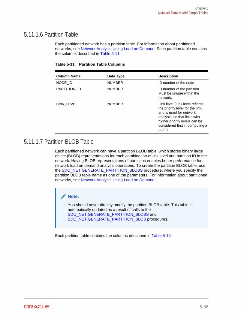
5.11.1.6 Partition TableEach partitioned network has a partition table. For information about partitionednetworks, see Network Analysis Using Load on Demand. Each partition table containsthe columns described in Table 5-11.
Table 5-11 Partition Table Columns
Column Name Data Type Description
NODE_ID NUMBER ID number of the node
PARTITION_ID NUMBER ID number of the partition.Must be unique within thenetwork.
LINK_LEVEL NUMBER Link level (Link level reflectsthe priority level for the link,and is used for networkanalysis, so that links withhigher priority levels can beconsidered first in computing apath.)
5.11.1.7 Partition BLOB TableEach partitioned network can have a partition BLOB table, which stores binary largeobject (BLOB) representations for each combination of link level and partition ID in thenetwork. Having BLOB representations of partitions enables better performance fornetwork load on demand analysis operations. To create the partition BLOB table, usethe SDO_NET.GENERATE_PARTITION_BLOBS procedure, where you specify thepartition BLOB table name as one of the parameters. For information about partitionednetworks, see Network Analysis Using Load on Demand.
Note:
You should never directly modify the partition BLOB table. This table isautomatically updated as a result of calls to the SDO_NET.GENERATE_PARTITION_BLOBS and SDO_NET.GENERATE_PARTITION_BLOB procedures.
Each partition table contains the columns described in Table 5-12.
Chapter 5Network Data Model Graph Tables
5-36
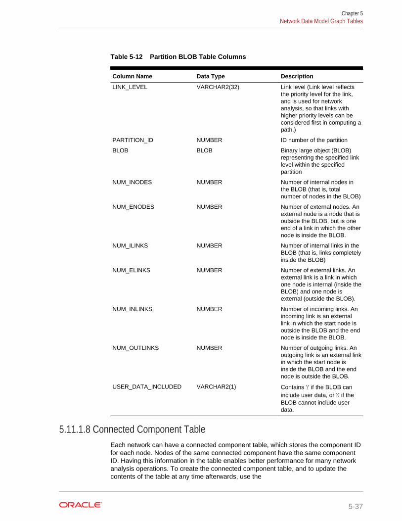
Table 5-12 Partition BLOB Table Columns
Column Name Data Type Description
LINK_LEVEL VARCHAR2(32) Link level (Link level reflectsthe priority level for the link,and is used for networkanalysis, so that links withhigher priority levels can beconsidered first in computing apath.)
PARTITION_ID NUMBER ID number of the partition
BLOB BLOB Binary large object (BLOB)representing the specified linklevel within the specifiedpartition
NUM_INODES NUMBER Number of internal nodes inthe BLOB (that is, totalnumber of nodes in the BLOB)
NUM_ENODES NUMBER Number of external nodes. Anexternal node is a node that isoutside the BLOB, but is oneend of a link in which the othernode is inside the BLOB.
NUM_ILINKS NUMBER Number of internal links in theBLOB (that is, links completelyinside the BLOB)
NUM_ELINKS NUMBER Number of external links. Anexternal link is a link in whichone node is internal (inside theBLOB) and one node isexternal (outside the BLOB).
NUM_INLINKS NUMBER Number of incoming links. Anincoming link is an externallink in which the start node isoutside the BLOB and the endnode is inside the BLOB.
NUM_OUTLINKS NUMBER Number of outgoing links. Anoutgoing link is an external linkin which the start node isinside the BLOB and the endnode is outside the BLOB.
USER_DATA_INCLUDED VARCHAR2(1) Contains Y if the BLOB caninclude user data, or N if theBLOB cannot include userdata.
5.11.1.8 Connected Component TableEach network can have a connected component table, which stores the component IDfor each node. Nodes of the same connected component have the same componentID. Having this information in the table enables better performance for many networkanalysis operations. To create the connected component table, and to update thecontents of the table at any time afterwards, use the
Chapter 5Network Data Model Graph Tables
5-37
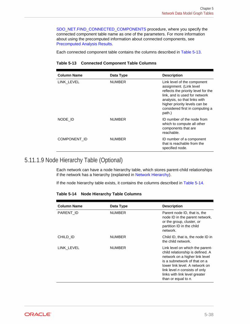
SDO_NET.FIND_CONNECTED_COMPONENTS procedure, where you specify theconnected component table name as one of the parameters. For more informationabout using the precomputed information about connected components, see Precomputed Analysis Results.
Each connected component table contains the columns described in Table 5-13.
Table 5-13 Connected Component Table Columns
Column Name Data Type Description
LINK_LEVEL NUMBER Link level of the componentassignment. (Link levelreflects the priority level for thelink, and is used for networkanalysis, so that links withhigher priority levels can beconsidered first in computing apath.)
NODE_ID NUMBER ID number of the node fromwhich to compute all othercomponents that arereachable.
COMPONENT_ID NUMBER ID number of a componentthat is reachable from thespecified node.
5.11.1.9 Node Hierarchy Table (Optional)Each network can have a node hierarchy table, which stores parent-child relationshipsif the network has a hierarchy (explained in Network Hierarchy).
If the node hierarchy table exists, it contains the columns described in Table 5-14.
Table 5-14 Node Hierarchy Table Columns
Column Name Data Type Description
PARENT_ID NUMBER Parent node ID, that is, thenode ID in the parent network,or the group, cluster, orpartition ID in the childnetwork.
CHILD_ID NUMBER Child ID, that is, the node ID inthe child network.
LINK_LEVEL NUMBER Link level on which the parent-child relationship is defined. Anetwork on a higher link levelis a subnetwork of that on alower link level. A network onlink level n consists of onlylinks with link level greaterthan or equal to n.
Chapter 5Network Data Model Graph Tables
5-38
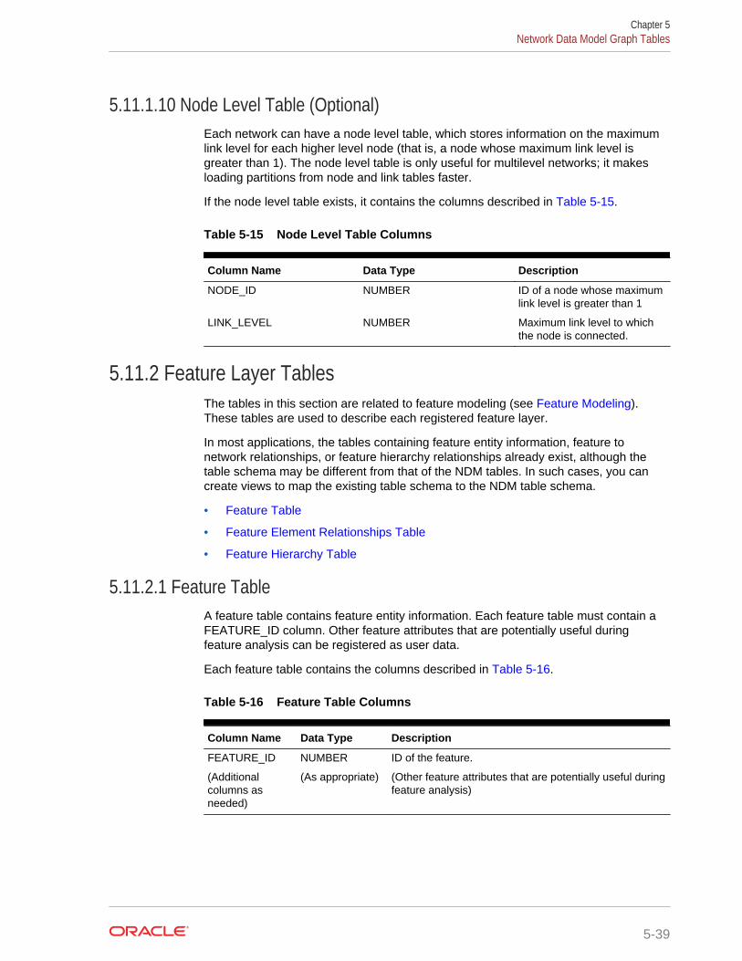
5.11.1.10 Node Level Table (Optional)Each network can have a node level table, which stores information on the maximumlink level for each higher level node (that is, a node whose maximum link level isgreater than 1). The node level table is only useful for multilevel networks; it makesloading partitions from node and link tables faster.
If the node level table exists, it contains the columns described in Table 5-15.
Table 5-15 Node Level Table Columns
Column Name Data Type Description
NODE_ID NUMBER ID of a node whose maximumlink level is greater than 1
LINK_LEVEL NUMBER Maximum link level to whichthe node is connected.
5.11.2 Feature Layer TablesThe tables in this section are related to feature modeling (see Feature Modeling).These tables are used to describe each registered feature layer.
In most applications, the tables containing feature entity information, feature tonetwork relationships, or feature hierarchy relationships already exist, although thetable schema may be different from that of the NDM tables. In such cases, you cancreate views to map the existing table schema to the NDM table schema.
• Feature Table
• Feature Element Relationships Table
• Feature Hierarchy Table
5.11.2.1 Feature TableA feature table contains feature entity information. Each feature table must contain aFEATURE_ID column. Other feature attributes that are potentially useful duringfeature analysis can be registered as user data.
Each feature table contains the columns described in Table 5-16.
Table 5-16 Feature Table Columns
Column Name Data Type Description
FEATURE_ID NUMBER ID of the feature.
(Additionalcolumns asneeded)
(As appropriate) (Other feature attributes that are potentially useful duringfeature analysis)
Chapter 5Network Data Model Graph Tables
5-39
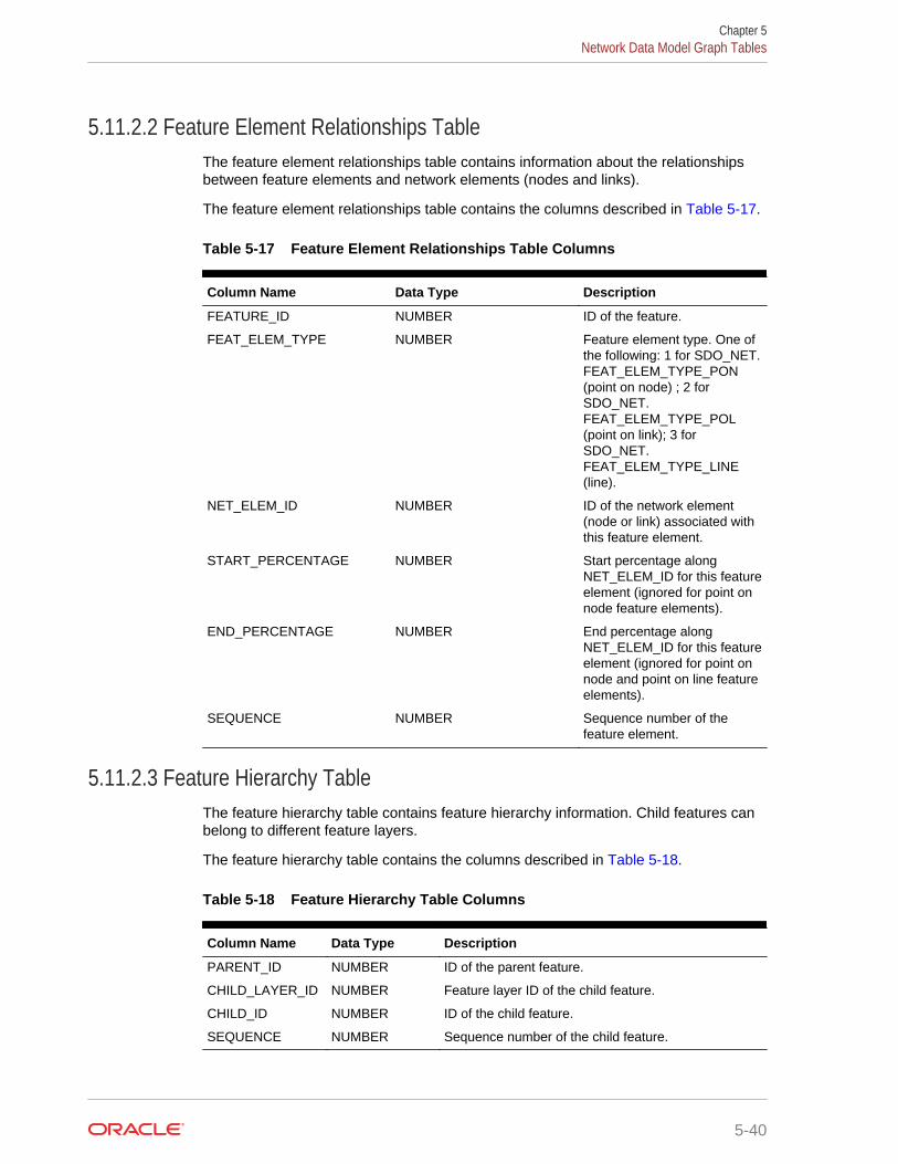
5.11.2.2 Feature Element Relationships TableThe feature element relationships table contains information about the relationshipsbetween feature elements and network elements (nodes and links).
The feature element relationships table contains the columns described in Table 5-17.
Table 5-17 Feature Element Relationships Table Columns
Column Name Data Type Description
FEATURE_ID NUMBER ID of the feature.
FEAT_ELEM_TYPE NUMBER Feature element type. One ofthe following: 1 for SDO_NET.FEAT_ELEM_TYPE_PON(point on node) ; 2 forSDO_NET.FEAT_ELEM_TYPE_POL(point on link); 3 forSDO_NET.FEAT_ELEM_TYPE_LINE(line).
NET_ELEM_ID NUMBER ID of the network element(node or link) associated withthis feature element.
START_PERCENTAGE NUMBER Start percentage alongNET_ELEM_ID for this featureelement (ignored for point onnode feature elements).
END_PERCENTAGE NUMBER End percentage alongNET_ELEM_ID for this featureelement (ignored for point onnode and point on line featureelements).
SEQUENCE NUMBER Sequence number of thefeature element.
5.11.2.3 Feature Hierarchy TableThe feature hierarchy table contains feature hierarchy information. Child features canbelong to different feature layers.
The feature hierarchy table contains the columns described in Table 5-18.
Table 5-18 Feature Hierarchy Table Columns
Column Name Data Type Description
PARENT_ID NUMBER ID of the parent feature.
CHILD_LAYER_ID NUMBER Feature layer ID of the child feature.
CHILD_ID NUMBER ID of the child feature.
SEQUENCE NUMBER Sequence number of the child feature.
Chapter 5Network Data Model Graph Tables
5-40

5.11.3 Network Feature Editing (NFE) Model TablesThe tables in this section are related to feature manipulation using Network FeatureEditing (NFE) (see Feature Modeling Using Network Feature Editing (NFE)). Thesetables are used to describe each NFE model.
In most cases, these tables are created or updated automatically when a new NFEModel is created using the PL/SQL function SDO_NFE.CREATE_MODEL_STRUCTURE or the Java API; but you can alsomanually create the tables or views and register them to the desired model.
• Automatically Created Points Default Attributes TableThe automatically created points default attributes table contains information aboutthe default values for the attributes of automatically created points as the result ofthe execution of a connectivity line-line rule.
• Connectivity Line-Line Rules TableThe connectivity line-line rules table contains the information about the definition ofconnectivity line-line rules applicable to features involved in an NFE model.
• Connectivity Line-Point Rules TableThe connectivity line-point rules table contains the information about the definitionof connectivity line-point rules applicable to features involved in an NFE model.
• Feature Class TableA feature class is related to a feature. A feature class table contains the records ofall feature classes from a feature layer, and must contain the columns described inthe following table.
• Feature Class Attributes Constraints TableThe feature class attributes constraints table contains information about userrestrictions over feature class attributes, which are the same attributes defined forthe feature layer that the feature class belongs to.
• Feature Class Default Predefined Connected Points TableThe feature class default predefined connected points table contains theinformation about such default connected point features along a line featuredescribed by a feature class.
• Feature Class Relationship TableThe feature class relationship table contains information about the relationshipbetween features and feature classes, that is, which feature belongs to whichfeature class.
• Feature Rule Relationship TableThe feature rule relationship table contains information that relates each featureelement involved in a rule, with the rule that caused its generation or connection.
• Feature User Data TableThe feature user data table contains he information of feature class attributes of acatalog type.
• Feature User Data Catalog TableYou can assign a value to a feature class attribute from a catalog; this is, that theattribute type from a feature class can be a catalog type. The feature user datacatalog table keeps a register of the catalogs that can be used for that purpose.
Chapter 5Network Data Model Graph Tables
5-41
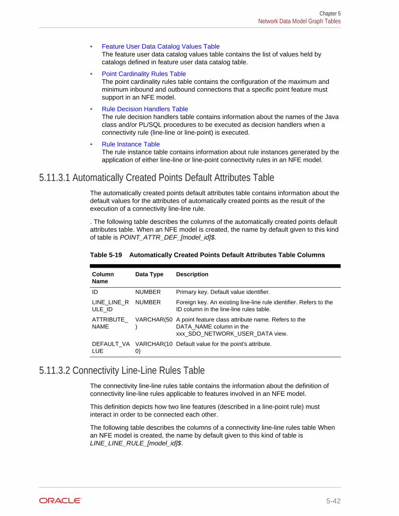
• Feature User Data Catalog Values TableThe feature user data catalog values table contains the list of values held bycatalogs defined in feature user data catalog table.
• Point Cardinality Rules TableThe point cardinality rules table contains the configuration of the maximum andminimum inbound and outbound connections that a specific point feature mustsupport in an NFE model.
• Rule Decision Handlers TableThe rule decision handlers table contains information about the names of the Javaclass and/or PL/SQL procedures to be executed as decision handlers when aconnectivity rule (line-line or line-point) is executed.
• Rule Instance TableThe rule instance table contains information about rule instances generated by theapplication of either line-line or line-point connectivity rules in an NFE model.
5.11.3.1 Automatically Created Points Default Attributes TableThe automatically created points default attributes table contains information about thedefault values for the attributes of automatically created points as the result of theexecution of a connectivity line-line rule.
. The following table describes the columns of the automatically created points defaultattributes table. When an NFE model is created, the name by default given to this kindof table is POINT_ATTR_DEF_[model_id]$.
Table 5-19 Automatically Created Points Default Attributes Table Columns
ColumnName
Data Type Description
ID NUMBER Primary key. Default value identifier.
LINE_LINE_RULE_ID
NUMBER Foreign key. An existing line-line rule identifier. Refers to theID column in the line-line rules table.
ATTRIBUTE_NAME
VARCHAR(50)
A point feature class attribute name. Refers to theDATA_NAME column in thexxx_SDO_NETWORK_USER_DATA view.
DEFAULT_VALUE
VARCHAR(100)
Default value for the point's attribute.
5.11.3.2 Connectivity Line-Line Rules TableThe connectivity line-line rules table contains the information about the definition ofconnectivity line-line rules applicable to features involved in an NFE model.
This definition depicts how two line features (described in a line-point rule) mustinteract in order to be connected each other.
The following table describes the columns of a connectivity line-line rules table Whenan NFE model is created, the name by default given to this kind of table isLINE_LINE_RULE_[model_id]$.
Chapter 5Network Data Model Graph Tables
5-42

Table 5-20 Connectivity Line-Line Rules Table Columns
ColumnName
Data Type Description
ID NUMBER Primary key. Line-line rule identifier.
LINE_POINT_1_ID
NUMBER Foreign key. An existing line-point rule identifier. Refers to theID column from a line point rules table.
LINE_POINT_2_ID
NUMBER Foreign key. An existing line-point rule identifier. Refers to theID column from a line point rules table.
INTERACTION NUMBER Interaction type between the two lines. Posible values: 1 =Crosses, 2 = Touches end points, 3 = Touches middle points,4 = Touches any point, 5 = Any interact
DECISION_HANDLER_ID
NUMBER Foreign key. The ID of the decision handler (if any) associatedwith the rule. Refrs to the ID column in the rules decisionhandler table.
CREATE_POINT
VARCHAR2(1)
Specifies whether the connection point should be createdautomatically or not when the interaction among feature linesoccurs. Possible values: ‘Y’, ‘N’.
5.11.3.3 Connectivity Line-Point Rules TableThe connectivity line-point rules table contains the information about the definition ofconnectivity line-point rules applicable to features involved in an NFE model.
This definition includes specifications of feature layer, feature class, and featureattributes conditions for both line and point interacting features that can be connected.
The following table describes the columns of a connectivity line-point rules table Whenan NFE model is created, the name by default given to this kind of table isLINE_POINT_RULE_[model_id]$.
Table 5-21 Connectivity Line-Point Rules Table Columns
Column Name Data Type Description
ID NUMBER Primary key. Line-point rule identifier.
LINE_FEATURE_LAYER_ID
NUMBER Feature layer identifier to which the line belongs. Refers tothe xxx_SDO_NETWORK_FEATURE table. A value of -1means all feature layers.
LINE_FEATURE_CLASS_ID
NUMBER Feature class identifier for the line to which the rule will beapplied. A value of -1 means all feature classes.
LINE_ATTRIBUTE_CONDITION
VARCHAR2(200)
Condition to be evaluated in the rule over the feature lineattributes. Example: MATERIAL = 'IRON'
POINT_FEATURE_LAYER_ID
NUMBER Feature layer identifier to which allowed connection pointbelongs. Refers to the xxx_SDO_NETWORK_FEATUREtable.
POINT_FEATURE_CLASS_ID
NUMBER Feature class identifier for the allowed connection point. Avalue of -1 means all feature classes.
DECISION_HANDLER_ID
NUMBER Foreign key. The ID of the decision handler (if any)associated with the rule. Refers to the ID column from therule decision handler table.
Chapter 5Network Data Model Graph Tables
5-43
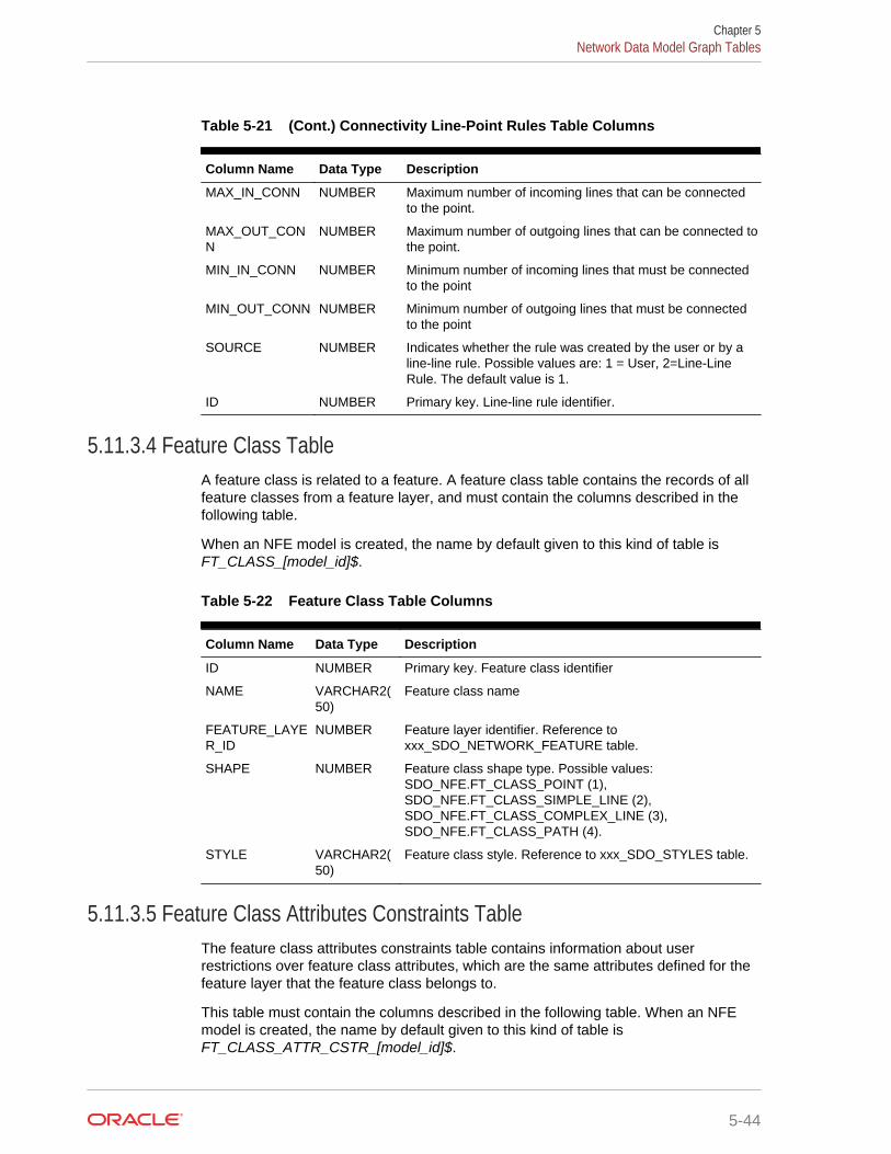
Table 5-21 (Cont.) Connectivity Line-Point Rules Table Columns
Column Name Data Type Description
MAX_IN_CONN NUMBER Maximum number of incoming lines that can be connectedto the point.
MAX_OUT_CONN
NUMBER Maximum number of outgoing lines that can be connected tothe point.
MIN_IN_CONN NUMBER Minimum number of incoming lines that must be connectedto the point
MIN_OUT_CONN NUMBER Minimum number of outgoing lines that must be connectedto the point
SOURCE NUMBER Indicates whether the rule was created by the user or by aline-line rule. Possible values are: 1 = User, 2=Line-LineRule. The default value is 1.
ID NUMBER Primary key. Line-line rule identifier.
5.11.3.4 Feature Class TableA feature class is related to a feature. A feature class table contains the records of allfeature classes from a feature layer, and must contain the columns described in thefollowing table.
When an NFE model is created, the name by default given to this kind of table isFT_CLASS_[model_id]$.
Table 5-22 Feature Class Table Columns
Column Name Data Type Description
ID NUMBER Primary key. Feature class identifier
NAME VARCHAR2(50)
Feature class name
FEATURE_LAYER_ID
NUMBER Feature layer identifier. Reference toxxx_SDO_NETWORK_FEATURE table.
SHAPE NUMBER Feature class shape type. Possible values:SDO_NFE.FT_CLASS_POINT (1),SDO_NFE.FT_CLASS_SIMPLE_LINE (2),SDO_NFE.FT_CLASS_COMPLEX_LINE (3),SDO_NFE.FT_CLASS_PATH (4).
STYLE VARCHAR2(50)
Feature class style. Reference to xxx_SDO_STYLES table.
5.11.3.5 Feature Class Attributes Constraints TableThe feature class attributes constraints table contains information about userrestrictions over feature class attributes, which are the same attributes defined for thefeature layer that the feature class belongs to.
This table must contain the columns described in the following table. When an NFEmodel is created, the name by default given to this kind of table isFT_CLASS_ATTR_CSTR_[model_id]$.
Chapter 5Network Data Model Graph Tables
5-44
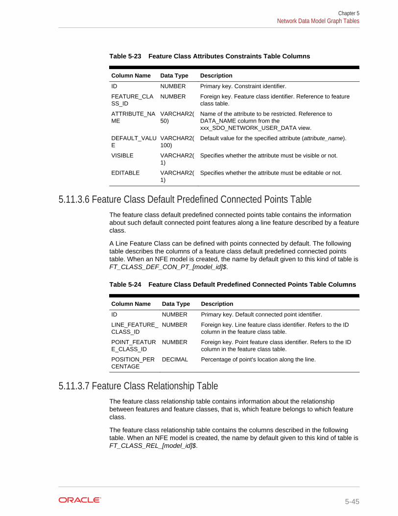
Table 5-23 Feature Class Attributes Constraints Table Columns
Column Name Data Type Description
ID NUMBER Primary key. Constraint identifier.
FEATURE_CLASS_ID
NUMBER Foreign key. Feature class identifier. Reference to featureclass table.
ATTRIBUTE_NAME
VARCHAR2(50)
Name of the attribute to be restricted. Reference toDATA_NAME column from thexxx_SDO_NETWORK_USER_DATA view.
DEFAULT_VALUE
VARCHAR2(100)
Default value for the specified attribute (attribute_name).
VISIBLE VARCHAR2(1)
Specifies whether the attribute must be visible or not.
EDITABLE VARCHAR2(1)
Specifies whether the attribute must be editable or not.
5.11.3.6 Feature Class Default Predefined Connected Points TableThe feature class default predefined connected points table contains the informationabout such default connected point features along a line feature described by a featureclass.
A Line Feature Class can be defined with points connected by default. The followingtable describes the columns of a feature class default predefined connected pointstable. When an NFE model is created, the name by default given to this kind of table isFT_CLASS_DEF_CON_PT_[model_id]$.
Table 5-24 Feature Class Default Predefined Connected Points Table Columns
Column Name Data Type Description
ID NUMBER Primary key. Default connected point identifier.
LINE_FEATURE_CLASS_ID
NUMBER Foreign key. Line feature class identifier. Refers to the IDcolumn in the feature class table.
POINT_FEATURE_CLASS_ID
NUMBER Foreign key. Point feature class identifier. Refers to the IDcolumn in the feature class table.
POSITION_PERCENTAGE
DECIMAL Percentage of point's location along the line.
5.11.3.7 Feature Class Relationship TableThe feature class relationship table contains information about the relationshipbetween features and feature classes, that is, which feature belongs to which featureclass.
The feature class relationship table contains the columns described in the followingtable. When an NFE model is created, the name by default given to this kind of table isFT_CLASS_REL_[model_id]$.
Chapter 5Network Data Model Graph Tables
5-45
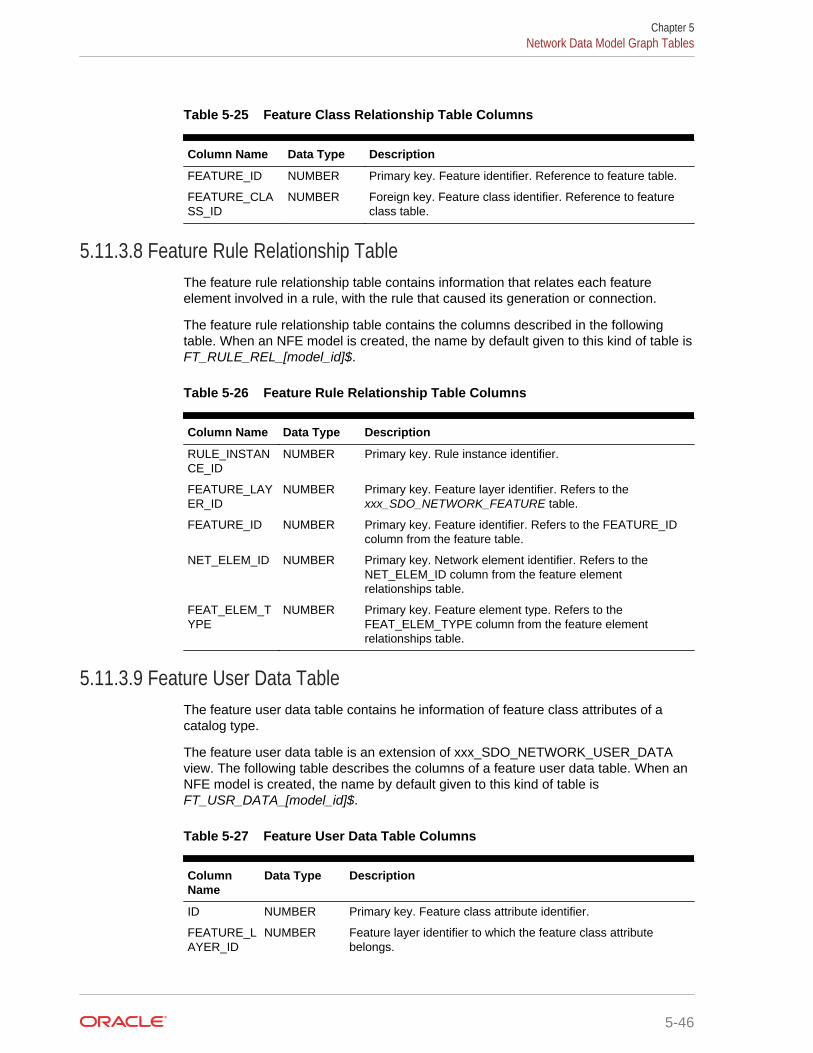
Table 5-25 Feature Class Relationship Table Columns
Column Name Data Type Description
FEATURE_ID NUMBER Primary key. Feature identifier. Reference to feature table.
FEATURE_CLASS_ID
NUMBER Foreign key. Feature class identifier. Reference to featureclass table.
5.11.3.8 Feature Rule Relationship TableThe feature rule relationship table contains information that relates each featureelement involved in a rule, with the rule that caused its generation or connection.
The feature rule relationship table contains the columns described in the followingtable. When an NFE model is created, the name by default given to this kind of table isFT_RULE_REL_[model_id]$.
Table 5-26 Feature Rule Relationship Table Columns
Column Name Data Type Description
RULE_INSTANCE_ID
NUMBER Primary key. Rule instance identifier.
FEATURE_LAYER_ID
NUMBER Primary key. Feature layer identifier. Refers to thexxx_SDO_NETWORK_FEATURE table.
FEATURE_ID NUMBER Primary key. Feature identifier. Refers to the FEATURE_IDcolumn from the feature table.
NET_ELEM_ID NUMBER Primary key. Network element identifier. Refers to theNET_ELEM_ID column from the feature elementrelationships table.
FEAT_ELEM_TYPE
NUMBER Primary key. Feature element type. Refers to theFEAT_ELEM_TYPE column from the feature elementrelationships table.
5.11.3.9 Feature User Data TableThe feature user data table contains he information of feature class attributes of acatalog type.
The feature user data table is an extension of xxx_SDO_NETWORK_USER_DATAview. The following table describes the columns of a feature user data table. When anNFE model is created, the name by default given to this kind of table isFT_USR_DATA_[model_id]$.
Table 5-27 Feature User Data Table Columns
ColumnName
Data Type Description
ID NUMBER Primary key. Feature class attribute identifier.
FEATURE_LAYER_ID
NUMBER Feature layer identifier to which the feature class attributebelongs.
Chapter 5Network Data Model Graph Tables
5-46

Table 5-27 (Cont.) Feature User Data Table Columns
ColumnName
Data Type Description
ATTRIBUTE_NAME
VARCHAR2(50)
Attribute name. Refers to the DATA_NAME column of thexxx_SDO_NETWORK_USER_DATA view.
CATALOG_ID
NUMBER Foreign key. Catalog identifier. Refers to the ID column from thefeature user data catalog table.
5.11.3.10 Feature User Data Catalog TableYou can assign a value to a feature class attribute from a catalog; this is, that theattribute type from a feature class can be a catalog type. The feature user data catalogtable keeps a register of the catalogs that can be used for that purpose.
The following table describes the columns that a feature user data catalog table mustcontain. When an NFE model is created, the name by default given to this kind of tableis FT_USR_DATA_CATLG_[model_id]$.
Table 5-28 Feature User Data Catalog Table Columns
ColumnName
Data Type Description
ID NUMBER Primary key. Catalog identifier.
NAME VARCHAR2(200)
Catalog name.
DATA_TYPE VARCHAR2(12)
Catalog data type (for example, Number or Varchar2).
5.11.3.11 Feature User Data Catalog Values TableThe feature user data catalog values table contains the list of values held by catalogsdefined in feature user data catalog table.
The following table describes the columns that a feature user data catalog values tablemust contain. When an NFE model is created, the name by default given to this kind oftable is FT_USR_DATA_CVAL_[model_id]$.
Table 5-29 Feature User Data Catalog Values Table Columns
ColumnName
Data Type Description
ID NUMBER Primary key. Catalog entry identifier.
CATALOG_ID
NUMBER Foreign key. Catalog identifier. Reference to the feature userdata catalog table.
VALUE VARCHAR2(12)
Catalog entry.
Chapter 5Network Data Model Graph Tables
5-47
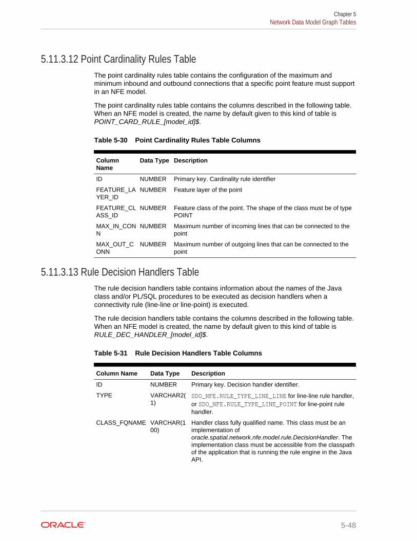
5.11.3.12 Point Cardinality Rules TableThe point cardinality rules table contains the configuration of the maximum andminimum inbound and outbound connections that a specific point feature must supportin an NFE model.
The point cardinality rules table contains the columns described in the following table.When an NFE model is created, the name by default given to this kind of table isPOINT_CARD_RULE_[model_id]$.
Table 5-30 Point Cardinality Rules Table Columns
ColumnName
Data Type Description
ID NUMBER Primary key. Cardinality rule identifier
FEATURE_LAYER_ID
NUMBER Feature layer of the point
FEATURE_CLASS_ID
NUMBER Feature class of the point. The shape of the class must be of typePOINT
MAX_IN_CONN
NUMBER Maximum number of incoming lines that can be connected to thepoint
MAX_OUT_CONN
NUMBER Maximum number of outgoing lines that can be connected to thepoint
5.11.3.13 Rule Decision Handlers TableThe rule decision handlers table contains information about the names of the Javaclass and/or PL/SQL procedures to be executed as decision handlers when aconnectivity rule (line-line or line-point) is executed.
The rule decision handlers table contains the columns described in the following table.When an NFE model is created, the name by default given to this kind of table isRULE_DEC_HANDLER_[model_id]$.
Table 5-31 Rule Decision Handlers Table Columns
Column Name Data Type Description
ID NUMBER Primary key. Decision handler identifier.
TYPE VARCHAR2(1)
SDO_NFE.RULE_TYPE_LINE_LINE for line-line rule handler,or SDO_NFE.RULE_TYPE_LINE_POINT for line-point rulehandler.
CLASS_FQNAME VARCHAR(100)
Handler class fully qualified name. This class must be animplementation oforacle.spatial.network.nfe.model.rule.DecisionHandler. Theimplementation class must be accessible from the classpathof the application that is running the rule engine in the JavaAPI.
Chapter 5Network Data Model Graph Tables
5-48
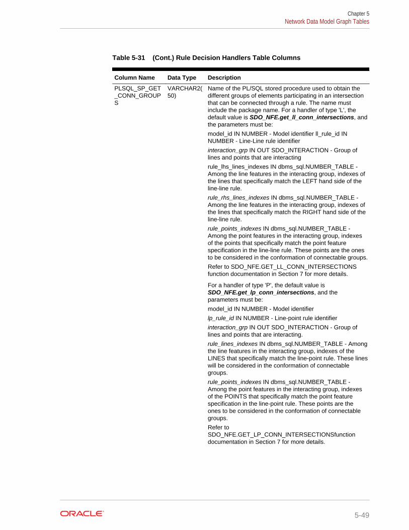
Table 5-31 (Cont.) Rule Decision Handlers Table Columns
Column Name Data Type Description
PLSQL_SP_GET_CONN_GROUPS
VARCHAR2(50)
Name of the PL/SQL stored procedure used to obtain thedifferent groups of elements participating in an intersectionthat can be connected through a rule. The name mustinclude the package name. For a handler of type 'L', thedefault value is SDO_NFE.get_ll_conn_intersections, andthe parameters must be:
model_id IN NUMBER - Model identifier ll_rule_id INNUMBER - Line-Line rule identifier
interaction_grp IN OUT SDO_INTERACTION - Group oflines and points that are interacting
rule_lhs_lines_indexes IN dbms_sql.NUMBER_TABLE -Among the line features in the interacting group, indexes ofthe lines that specifically match the LEFT hand side of theline-line rule.
rule_rhs_lines_indexes IN dbms_sql.NUMBER_TABLE -Among the line features in the interacting group, indexes ofthe lines that specifically match the RIGHT hand side of theline-line rule.
rule_points_indexes IN dbms_sql.NUMBER_TABLE -Among the point features in the interacting group, indexesof the points that specifically match the point featurespecification in the line-line rule. These points are the onesto be considered in the conformation of connectable groups.
Refer to SDO_NFE.GET_LL_CONN_INTERSECTIONSfunction documentation in Section 7 for more details.
For a handler of type 'P', the default value isSDO_NFE.get_lp_conn_intersections, and theparameters must be:
model_id IN NUMBER - Model identifier
lp_rule_id IN NUMBER - Line-point rule identifier
interaction_grp IN OUT SDO_INTERACTION - Group oflines and points that are interacting.
rule_lines_indexes IN dbms_sql.NUMBER_TABLE - Amongthe line features in the interacting group, indexes of theLINES that specifically match the line-point rule. These lineswill be considered in the conformation of connectablegroups.
rule_points_indexes IN dbms_sql.NUMBER_TABLE -Among the point features in the interacting group, indexesof the POINTS that specifically match the point featurespecification in the line-point rule. These points are theones to be considered in the conformation of connectablegroups.
Refer toSDO_NFE.GET_LP_CONN_INTERSECTIONSfunctiondocumentation in Section 7 for more details.
Chapter 5Network Data Model Graph Tables
5-49
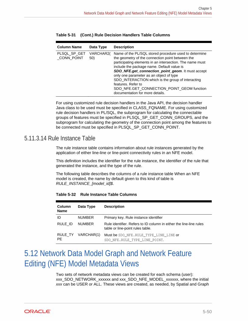
Table 5-31 (Cont.) Rule Decision Handlers Table Columns
Column Name Data Type Description
PLSQL_SP_GET_CONN_POINT
VARCHAR2(50)
Name of the PL/SQL stored procedure used to determinethe geometry of the connection point between theparticipating elements in an intersection. The name mustinclude the package name. Default value isSDO_NFE.get_connection_point_geom. It must acceptonly one parameter as an object of typeSDO_INTERACTION which is the group of interactingfeatures. Refer toSDO_NFE.GET_CONNECTION_POINT_GEOM functiondocumentation for more details.
For using customized rule decision handlers in the Java API, the decision handlerJava class to be used must be specified in CLASS_FQNAME. For using customizedrule decision handlers in PL/SQL, the subprogram for calculating the connectablegroups of features must be specified in PLSQL_SP_GET_CONN_GROUPS, and thesubprogram for calculating the geometry of the connection point among the features tobe connected must be specified in PLSQL_SP_GET_CONN_POINT.
5.11.3.14 Rule Instance TableThe rule instance table contains information about rule instances generated by theapplication of either line-line or line-point connectivity rules in an NFE model.
This definition includes the identifier for the rule instance, the identifier of the rule thatgenerated the instance, and the type of the rule.
The following table describes the columns of a rule instance table When an NFEmodel is created, the name by default given to this kind of table isRULE_INSTANCE_[model_id]$.
Table 5-32 Rule Instance Table Columns
ColumnName
Data Type Description
ID NUMBER Primary key. Rule instance identifier
RULE_ID NUMBER Rule identifier. Refers to ID column in either the line-line rulestable or line-point rules table.
RULE_TYPE
VARCHAR(1) Must be SDO_NFE.RULE_TYPE_LINE_LINE orSDO_NFE.RULE_TYPE_LINE_POINT.
5.12 Network Data Model Graph and Network FeatureEditing (NFE) Model Metadata Views
Two sets of network metadata views can be created for each schema (user):xxx_SDO_NETWORK_xxxxxx and xxx_SDO_NFE_MODEL_xxxxxx, where the initialxxx can be USER or ALL. These views are created, as needed, by Spatial and Graph
Chapter 5Network Data Model Graph and Network Feature Editing (NFE) Model Metadata Views
5-50
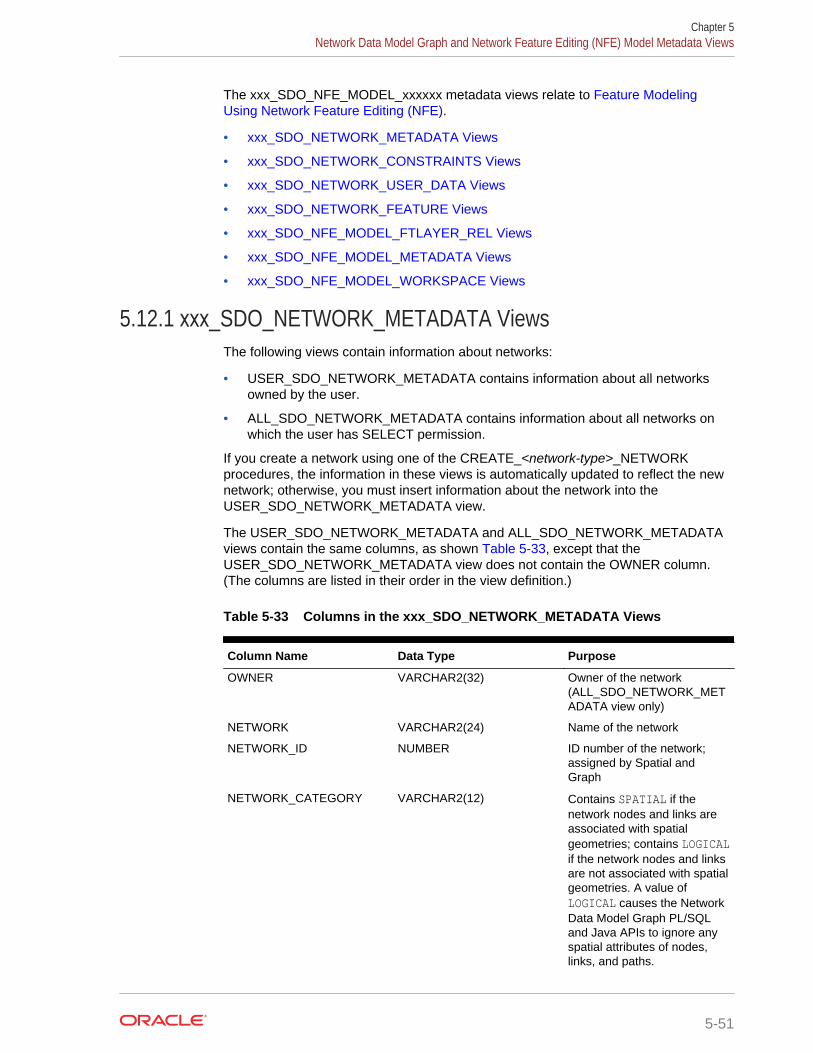
The xxx_SDO_NFE_MODEL_xxxxxx metadata views relate to Feature ModelingUsing Network Feature Editing (NFE).
• xxx_SDO_NETWORK_METADATA Views
• xxx_SDO_NETWORK_CONSTRAINTS Views
• xxx_SDO_NETWORK_USER_DATA Views
• xxx_SDO_NETWORK_FEATURE Views
• xxx_SDO_NFE_MODEL_FTLAYER_REL Views
• xxx_SDO_NFE_MODEL_METADATA Views
• xxx_SDO_NFE_MODEL_WORKSPACE Views
5.12.1 xxx_SDO_NETWORK_METADATA ViewsThe following views contain information about networks:
• USER_SDO_NETWORK_METADATA contains information about all networksowned by the user.
• ALL_SDO_NETWORK_METADATA contains information about all networks onwhich the user has SELECT permission.
If you create a network using one of the CREATE_<network-type>_NETWORKprocedures, the information in these views is automatically updated to reflect the newnetwork; otherwise, you must insert information about the network into theUSER_SDO_NETWORK_METADATA view.
The USER_SDO_NETWORK_METADATA and ALL_SDO_NETWORK_METADATAviews contain the same columns, as shown Table 5-33, except that theUSER_SDO_NETWORK_METADATA view does not contain the OWNER column.(The columns are listed in their order in the view definition.)
Table 5-33 Columns in the xxx_SDO_NETWORK_METADATA Views
Column Name Data Type Purpose
OWNER VARCHAR2(32) Owner of the network(ALL_SDO_NETWORK_METADATA view only)
NETWORK VARCHAR2(24) Name of the network
NETWORK_ID NUMBER ID number of the network;assigned by Spatial andGraph
NETWORK_CATEGORY VARCHAR2(12) Contains SPATIAL if thenetwork nodes and links areassociated with spatialgeometries; contains LOGICALif the network nodes and linksare not associated with spatialgeometries. A value ofLOGICAL causes the NetworkData Model Graph PL/SQLand Java APIs to ignore anyspatial attributes of nodes,links, and paths.
Chapter 5Network Data Model Graph and Network Feature Editing (NFE) Model Metadata Views
5-51

Table 5-33 (Cont.) Columns in the xxx_SDO_NETWORK_METADATA Views
Column Name Data Type Purpose
GEOMETRY_TYPE VARCHAR2(24) If NETWORK_CATEGORY isSPATIAL, contains a valueindicating the geometry type ofnodes and links:SDO_GEOMETRY for non-LRSSDO_GEOMETRY objects,LRS_GEOMETRY for LRSSDO_GEOMETRY objects,TOPO_GEOMETRY forSDO_TOPO_GEOMETRYobjects.
NETWORK_TYPE VARCHAR2(24) User-defined string to identifythe network type.
NO_OF_HIERARCHY_LEVELS
NUMBER Number of levels in thenetwork hierarchy. Contains 1if there is no hierarchy. (See Network Hierarchy forinformation about networkhierarchy.)
NO_OF_PARTITIONS NUMBER (Not currently used)
LRS_TABLE_NAME VARCHAR2(32) If GEOMETRY_TYPE isSDO_GEOMETRY, contains thename of the table containinggeometries associated withnodes.
LRS_GEOM_COLUMN VARCHAR2(32) If LRS_TABLE_NAME containsa table name, identifies thegeometry column in that table.
NODE_TABLE_NAME VARCHAR2(32) If GEOMETRY_TYPE isSDO_GEOMETRY, contains thename of the table containinggeometries associated withnodes. (The node table isdescribed in Node Table.)
NODE_GEOM_COLUMN VARCHAR2(32) If NODE_TABLE_NAME containsa table name, identifies thegeometry column in that table.
NODE_COST_COLUMN VARCHAR2(1024) If NODE_TABLE_NAME containsa table name, identifies thecost column in that table, or aPL/SQL function to computethe cost value.
NODE_PARTITION_COLUMN
VARCHAR2(32) (Not currently used).
Chapter 5Network Data Model Graph and Network Feature Editing (NFE) Model Metadata Views
5-52

Table 5-33 (Cont.) Columns in the xxx_SDO_NETWORK_METADATA Views
Column Name Data Type Purpose
NODE_DURATION_COLUMN VARCHAR2(32) If NODE_TABLE_NAME containsa table name, identifies theoptional duration column inthat table. This column cancontain a numeric value thathas any user-definedsignificance, such as anumber of minutes associatedwith the node.
LINK_TABLE_NAME VARCHAR2(32) If GEOMETRY_TYPE isSDO_GEOMETRY, contains thename of the table containinggeometries associated withlinks. (The link table isdescribed in Link Table.)
LINK_GEOM_COLUMN VARCHAR2(32) If LINK_TABLE_NAME containsa table name, identifies thegeometry column in that table.
LINK_DIRECTION VARCHAR2(12) Contains a value indicating thetype for all links in thenetwork: UNDIRECTED orDIRECTED.
LINK_COST_COLUMN VARCHAR2(1024) If LINK_TABLE_NAME containsa table name, identifies theoptional numeric columncontaining a cost value foreach link, or a PL/SQLfunction to compute the costvalue.
LINK_PARTITION_COLUMN VARCHAR2(32) (Not currently used)
LINK_DURATION_COLUMN VARCHAR2(32) If LINK_TABLE_NAME containsa table name, identifies theoptional duration column inthat table. This column cancontain a numeric value thathas any user-definedsignificance, such as anumber of minutes associatedwith the link.
PATH_TABLE_NAME VARCHAR2(32) Contains the name of anoptional table containinginformation about paths. (Thepath table is described in PathTable.)
PATH_GEOM_COLUMN VARCHAR2(32) If PATH_TABLE_NAME isassociated with a spatialnetwork, identifies thegeometry column in that table.
Chapter 5Network Data Model Graph and Network Feature Editing (NFE) Model Metadata Views
5-53
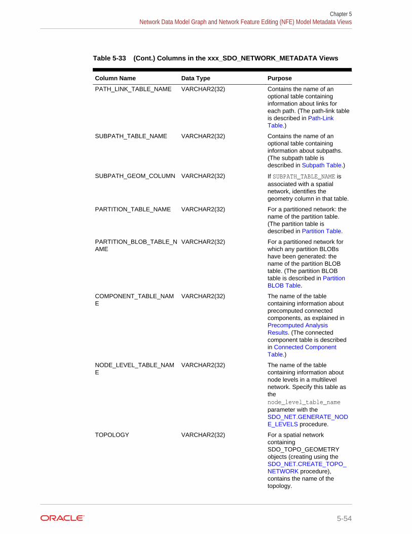
Table 5-33 (Cont.) Columns in the xxx_SDO_NETWORK_METADATA Views
Column Name Data Type Purpose
PATH_LINK_TABLE_NAME VARCHAR2(32) Contains the name of anoptional table containinginformation about links foreach path. (The path-link tableis described in Path-LinkTable.)
SUBPATH_TABLE_NAME VARCHAR2(32) Contains the name of anoptional table containinginformation about subpaths.(The subpath table isdescribed in Subpath Table.)
SUBPATH_GEOM_COLUMN VARCHAR2(32) If SUBPATH_TABLE_NAME isassociated with a spatialnetwork, identifies thegeometry column in that table.
PARTITION_TABLE_NAME VARCHAR2(32) For a partitioned network: thename of the partition table.(The partition table isdescribed in Partition Table.
PARTITION_BLOB_TABLE_NAME
VARCHAR2(32) For a partitioned network forwhich any partition BLOBshave been generated: thename of the partition BLOBtable. (The partition BLOBtable is described in PartitionBLOB Table.
COMPONENT_TABLE_NAME
VARCHAR2(32) The name of the tablecontaining information aboutprecomputed connectedcomponents, as explained in Precomputed AnalysisResults. (The connectedcomponent table is describedin Connected ComponentTable.)
NODE_LEVEL_TABLE_NAME
VARCHAR2(32) The name of the tablecontaining information aboutnode levels in a multilevelnetwork. Specify this table asthenode_level_table_nameparameter with the SDO_NET.GENERATE_NODE_LEVELS procedure.
TOPOLOGY VARCHAR2(32) For a spatial networkcontainingSDO_TOPO_GEOMETRYobjects (creating using the SDO_NET.CREATE_TOPO_NETWORK procedure),contains the name of thetopology.
Chapter 5Network Data Model Graph and Network Feature Editing (NFE) Model Metadata Views
5-54
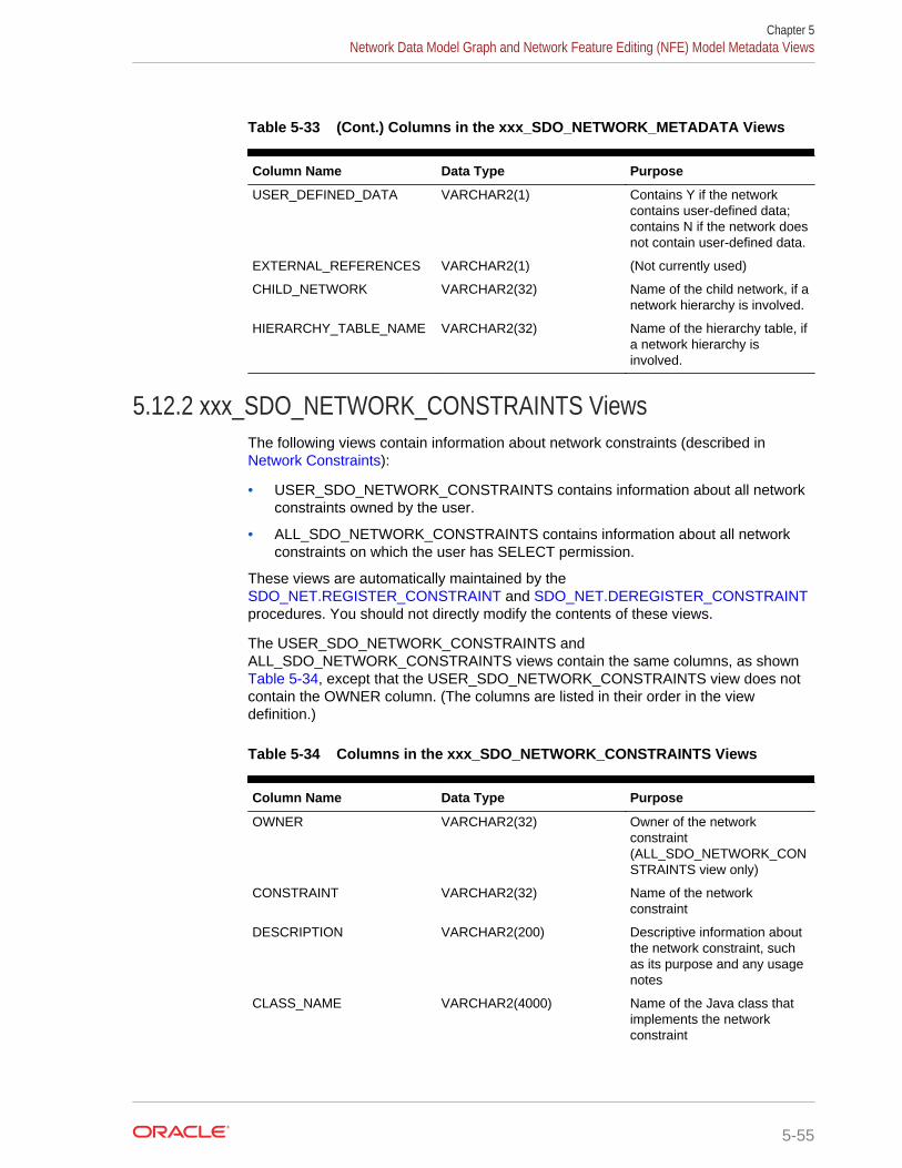
Table 5-33 (Cont.) Columns in the xxx_SDO_NETWORK_METADATA Views
Column Name Data Type Purpose
USER_DEFINED_DATA VARCHAR2(1) Contains Y if the networkcontains user-defined data;contains N if the network doesnot contain user-defined data.
EXTERNAL_REFERENCES VARCHAR2(1) (Not currently used)
CHILD_NETWORK VARCHAR2(32) Name of the child network, if anetwork hierarchy is involved.
HIERARCHY_TABLE_NAME VARCHAR2(32) Name of the hierarchy table, ifa network hierarchy isinvolved.
5.12.2 xxx_SDO_NETWORK_CONSTRAINTS ViewsThe following views contain information about network constraints (described in Network Constraints):
• USER_SDO_NETWORK_CONSTRAINTS contains information about all networkconstraints owned by the user.
• ALL_SDO_NETWORK_CONSTRAINTS contains information about all networkconstraints on which the user has SELECT permission.
These views are automatically maintained by the SDO_NET.REGISTER_CONSTRAINT and SDO_NET.DEREGISTER_CONSTRAINTprocedures. You should not directly modify the contents of these views.
The USER_SDO_NETWORK_CONSTRAINTS andALL_SDO_NETWORK_CONSTRAINTS views contain the same columns, as shown Table 5-34, except that the USER_SDO_NETWORK_CONSTRAINTS view does notcontain the OWNER column. (The columns are listed in their order in the viewdefinition.)
Table 5-34 Columns in the xxx_SDO_NETWORK_CONSTRAINTS Views
Column Name Data Type Purpose
OWNER VARCHAR2(32) Owner of the networkconstraint(ALL_SDO_NETWORK_CONSTRAINTS view only)
CONSTRAINT VARCHAR2(32) Name of the networkconstraint
DESCRIPTION VARCHAR2(200) Descriptive information aboutthe network constraint, suchas its purpose and any usagenotes
CLASS_NAME VARCHAR2(4000) Name of the Java class thatimplements the networkconstraint
Chapter 5Network Data Model Graph and Network Feature Editing (NFE) Model Metadata Views
5-55
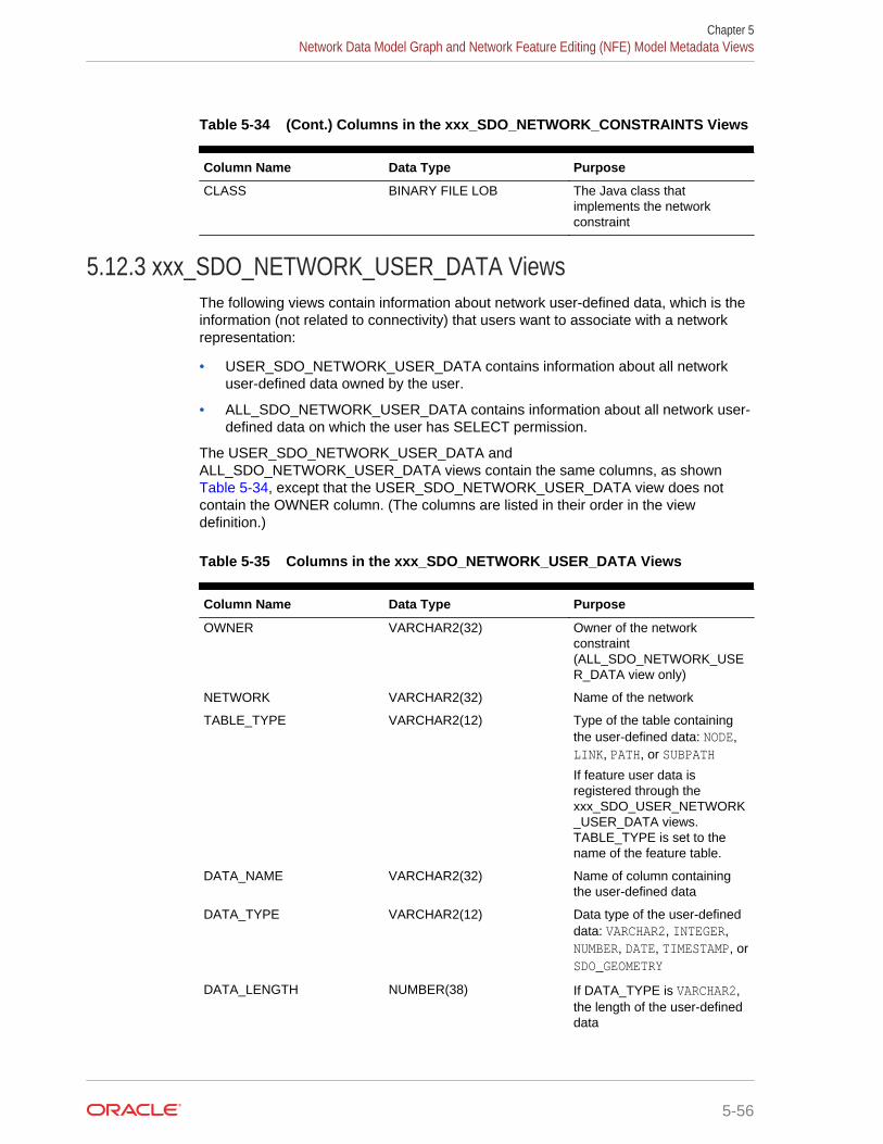
Table 5-34 (Cont.) Columns in the xxx_SDO_NETWORK_CONSTRAINTS Views
Column Name Data Type Purpose
CLASS BINARY FILE LOB The Java class thatimplements the networkconstraint
5.12.3 xxx_SDO_NETWORK_USER_DATA ViewsThe following views contain information about network user-defined data, which is theinformation (not related to connectivity) that users want to associate with a networkrepresentation:
• USER_SDO_NETWORK_USER_DATA contains information about all networkuser-defined data owned by the user.
• ALL_SDO_NETWORK_USER_DATA contains information about all network user-defined data on which the user has SELECT permission.
The USER_SDO_NETWORK_USER_DATA andALL_SDO_NETWORK_USER_DATA views contain the same columns, as shown Table 5-34, except that the USER_SDO_NETWORK_USER_DATA view does notcontain the OWNER column. (The columns are listed in their order in the viewdefinition.)
Table 5-35 Columns in the xxx_SDO_NETWORK_USER_DATA Views
Column Name Data Type Purpose
OWNER VARCHAR2(32) Owner of the networkconstraint(ALL_SDO_NETWORK_USER_DATA view only)
NETWORK VARCHAR2(32) Name of the network
TABLE_TYPE VARCHAR2(12) Type of the table containingthe user-defined data: NODE,LINK, PATH, or SUBPATH
If feature user data isregistered through thexxx_SDO_USER_NETWORK_USER_DATA views.TABLE_TYPE is set to thename of the feature table.
DATA_NAME VARCHAR2(32) Name of column containingthe user-defined data
DATA_TYPE VARCHAR2(12) Data type of the user-defineddata: VARCHAR2, INTEGER,NUMBER, DATE, TIMESTAMP, orSDO_GEOMETRY
DATA_LENGTH NUMBER(38) If DATA_TYPE is VARCHAR2,the length of the user-defineddata
Chapter 5Network Data Model Graph and Network Feature Editing (NFE) Model Metadata Views
5-56

Table 5-35 (Cont.) Columns in the xxx_SDO_NETWORK_USER_DATA Views
Column Name Data Type Purpose
CATEGORY_ID NUMBER User data category ID (non-negative number, default 0).The category ID allows forgrouping of user data fordifferent applications.Category 0 is reserved forgeneral-purpose user datathat is useful for allapplications. User data fordifferent purposes can begrouped into differentcategories, so that duringnetwork analysis, only therelevant user data categoriesare loaded into memory,reducing memoryconsumption at runtime.
For example, for a roadnetwork, category 0 user datacan include the speed limitand function class of links, andthe x, y coordinates of nodes;trucking-related user datamight belong to category 1;and traffic-related user datamight belong to category 2.
To use user-defined data, you must set the USER_DEFINED_DATA column value to Yin the appropriate xxx_SDO_NETWORK_METADATA views (described in xxx_SDO_NETWORK_METADATA Views).
For an example of using user-defined data, see User-Defined Data Examples (PL/SQLand Java).
For user data defined through the xxx_SDO_NETWORK_USER_DATA views, thedefault user data I/O implementation (LODUserDataIOSDO) is used to access the userdata during network analysis. However, some user data is not included in the node orlink table, and thus cannot be registered through xxx_SDO_NETWORK_USER_DATAviews. For such user data, you must provide your own implementation of the user dataI/O interface. A typical way of implementing a custom user data I/O interface is togenerate BLOBs corresponding to node and link user data , one BLOB for eachpartition, and then retrieve user data information from the BLOBs during networkanalysis.
You can also associate multiple categories of user-defined data (categorized userdata) with a single network. For example, in a multimodal network (described in Multimodal Network and Temporal Examples), if you must associate driving-relatedattributes (such as speed limit) with a link in addition to the link's multimodal attributes,you can organize user-defined data in two categories: one for driving-related attributesand the other for multimodal attributes.
Chapter 5Network Data Model Graph and Network Feature Editing (NFE) Model Metadata Views
5-57

5.12.4 xxx_SDO_NETWORK_FEATURE ViewsThe following views contain information about network feature layers (described in Features and Feature Layers):
• USER_SDO_NETWORK_FEATURE contains information about all networkfeature layers owned by the user.
• ALL_SDO_NETWORK_FEATURE contains information about all network featurelayers on which the user has SELECT permission.
The USER_SDO_NETWORK_FEATURE and ALL_SDO_NETWORK_FEATUREviews contain the same columns, as shown Table 5-34, except that theUSER_SDO_NETWORK_FEATURE view does not contain the OWNER column. (Thecolumns are listed in their order in the view definition.)
Table 5-36 Columns in the xxx_SDO_NETWORK_FEATURE Views
Column Name Data Type Purpose
OWNER VARCHAR2(32) Owner of the network featurelayer(ALL_SDO_NETWORK_FEATURE view only)
NETWORK VARCHAR2(32) Name of the network on whichthe feature layer is defined
FEATURE_LAYER_NAME VARCHAR2(32) Name of the feature layer
FEATURE_LAYER_ID NUMBER ID of the feature layer(assigned by Oracle Spatialand Graph)
FEATURE_LAYER_TYPE NUMBER Type of the feature layer (see Table 5-2 in Features andFeature Layers)
FEATURE_TABLE_NAME VARCHAR2(32) Name of the feature table (see Feature Table)
RELATION_TABLE_NAME VARCHAR2(32) Name of the feature elementrelationships table, whichmaps feature elements withnetwork elements (nodes andlinks) (see Feature ElementRelationships Table)
HIERRCHY_TABLE_NAME VARCHAR2(32) Name of the feature hierarchytable, which defines parent-child relationships betweenfeatures (see FeatureHierarchy Table)
To use user-defined data, you must set the USER_DEFINED_DATA column value to Yin the appropriate xxx_SDO_NETWORK_METADATA views (described in xxx_SDO_NETWORK_METADATA Views).
For an example of using user-defined data, see User-Defined Data Examples (PL/SQLand Java).
Chapter 5Network Data Model Graph and Network Feature Editing (NFE) Model Metadata Views
5-58

For user data defined through the xxx_SDO_NETWORK_USER_DATA views, thedefault user data I/O implementation (LODUserDataIOSDO) is used to access the userdata during network analysis. However, some user data is not included in the node orlink table, and thus cannot be registered through xxx_SDO_NETWORK_USER_DATAviews. For such user data, you must provide your own implementation of the user dataI/O interface. A typical way of implementing a custom user data I/O interface is togenerate BLOBs corresponding to node and link user data , one BLOB for eachpartition, and then retrieve user data information from the BLOBs during networkanalysis.
You can also associate multiple categories of user-defined data (categorized userdata) with a single network. For example, in a multimodal network (described in Multimodal Network and Temporal Examples), if you must associate driving-relatedattributes (such as speed limit) with a link in addition to the link's multimodal attributes,you can organize user-defined data in two categories: one for driving-related attributesand the other for multimodal attributes.
5.12.5 xxx_SDO_NFE_MODEL_FTLAYER_REL ViewsThe following views contain information about network feature layers related to NFEmodels. (This topic assumes you are familiar with the concepts explained in FeatureModeling Using Network Feature Editing (NFE).)
• USER_SDO_NFE_MODEL_FTLAYER_REL contains information about featurelayers that are related to all NFE models that are owned by the user.
• ALL_SDO_NFE_MODEL_FTLAYER_REL contains information about featurelayers that are related to NFE models on which the user has SELECT permission.
The USER_SDO_NFE_MODEL_FTLAYER_REL andALL_SDO_NFE_MODEL_FTLAYER_REL views contain the same columns, as shownin Table 5-37, except that the USER_SDO_NFE_MODEL_FTLAYER_REL view doesnot contain the OWNER column. (The columns are listed in their order in the viewdefinition.)
Table 5-37 Columns in the xxx_SDO_NFE_MODEL_FTLAYER_REL Views
Column Name Data Type Purpose
OWNER VARCHAR2(32) Owner of the NFE model(ALL_SDO_NFE_MODEL_FTLAYER_REL view only)
MODEL_ID NUMBER Identifier of the model relatedto a feature layer.
FEATURE_LAYER_ID NUMBER Identifier of the related featurelayer.
HIERARCHY_LEVEL NUMBER Hierarchical level for thefeature layer in the model. Thedefault is 0 (zero). Higherlevels are on top of lowerlevels.
Chapter 5Network Data Model Graph and Network Feature Editing (NFE) Model Metadata Views
5-59
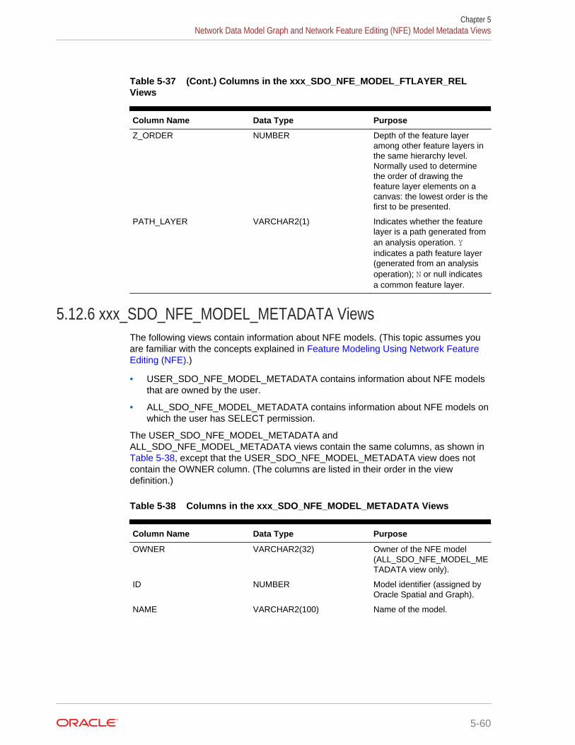
Table 5-37 (Cont.) Columns in the xxx_SDO_NFE_MODEL_FTLAYER_RELViews
Column Name Data Type Purpose
Z_ORDER NUMBER Depth of the feature layeramong other feature layers inthe same hierarchy level.Normally used to determinethe order of drawing thefeature layer elements on acanvas: the lowest order is thefirst to be presented.
PATH_LAYER VARCHAR2(1) Indicates whether the featurelayer is a path generated froman analysis operation. Yindicates a path feature layer(generated from an analysisoperation); N or null indicatesa common feature layer.
5.12.6 xxx_SDO_NFE_MODEL_METADATA ViewsThe following views contain information about NFE models. (This topic assumes youare familiar with the concepts explained in Feature Modeling Using Network FeatureEditing (NFE).)
• USER_SDO_NFE_MODEL_METADATA contains information about NFE modelsthat are owned by the user.
• ALL_SDO_NFE_MODEL_METADATA contains information about NFE models onwhich the user has SELECT permission.
The USER_SDO_NFE_MODEL_METADATA andALL_SDO_NFE_MODEL_METADATA views contain the same columns, as shown in Table 5-38, except that the USER_SDO_NFE_MODEL_METADATA view does notcontain the OWNER column. (The columns are listed in their order in the viewdefinition.)
Table 5-38 Columns in the xxx_SDO_NFE_MODEL_METADATA Views
Column Name Data Type Purpose
OWNER VARCHAR2(32) Owner of the NFE model(ALL_SDO_NFE_MODEL_METADATA view only).
ID NUMBER Model identifier (assigned byOracle Spatial and Graph).
NAME VARCHAR2(100) Name of the model.
Chapter 5Network Data Model Graph and Network Feature Editing (NFE) Model Metadata Views
5-60

Table 5-38 (Cont.) Columns in the xxx_SDO_NFE_MODEL_METADATA Views
Column Name Data Type Purpose
EDITION_MODE NUMBER Can be 1(SDO_NFE.FROM_SCRATCH) for models using a newnetwork, creating featuresalong with underlying networkelements, or 2(SDO_NFE.OVER_EXISTING_NETWORK) for models builton top of a currently existingnetwork (in which networkelements cannot be modified).
VERSIONABLE_IND VARCHAR2(1) Indicates whether the modelwill allow different versions orbranches. Y indicates a theyare allowed; N indicates theyare not allowed.
TABLE_REG_TAB VARCHAR2(50) Name of the table in which thenames of the Network FeatureEditing (NFE) Model Tablesare registered. This table isautomatically created andmaintained, and it has thecolumns described in Table 5-39.
SEQUENCE_REG_TAB VARCHAR2(50) Name of the table in which thesequences associated with themodel’s tables are registered.This table is automaticallycreated and maintained, and ithas the columns described in xxx_SDO_NFE_MODEL_METADATA Views.
NETWORK_NAME VARCHAR2(50) Name of the networkassociated with the model.
Chapter 5Network Data Model Graph and Network Feature Editing (NFE) Model Metadata Views
5-61

Table 5-39 Columns in the TABLE_REG_TAB Table
Column Name Data Type Purpose
TABLE_TYPE VARCHAR2(50) Primary Key. Type of the tableto be registered. Possiblevalues:SDO_NFE.FT_CLASS,SDO_NFE.FT_CLASS_REL,SDO_NFE.FT_CLASS_ATTR_CON,DO_NFE.FT_USR_DATA,SDO_NFE.FT_USR_DATA_CAT,SDO_NFE.FT_USR_DATA_CVAL,SDO_NFE.FT_CLASS_DEF_PTS,SDO_NFE.LINE_LINE_RULES,SDO_NFE.LINE_POINT_RULES,SDO_NFE.RULE_INSTANCE,SDO_NFE.FT_RULE_REL,SDO_NFE.RULE_DEC_HANDLER,SDO_NFE.POINT_CARD_RULES,SDO_NFE.POINT_ATTR_DEF
TABLE_NAME VARCHAR2(50) Name assigned to the table.When you use SDO_NET.ADD_CHILD_FEATURE, by default this name iscreated in the form[TABLE_TYPE]_[model_id]$.
Table 5-40 Columns in the SEQUENCE_REG_TAB Table
Column Name Data Type Purpose
TABLE_NAME VARCHAR2(50) Primary key. Name of thetable associated with thesequence..
SEQUENCE_NAME VARCHAR2(50) Name of the sequence..
5.12.7 xxx_SDO_NFE_MODEL_WORKSPACE ViewsThe following views contain information about workspaces related to NFE models.(This topic assumes you are familiar with the concepts explained in Feature ModelingUsing Network Feature Editing (NFE).)
• USER_SDO_NFE_MODEL_WORKSPACE contains information aboutworkspaces that are related to all NFE models that are owned by the user.
Chapter 5Network Data Model Graph and Network Feature Editing (NFE) Model Metadata Views
5-62
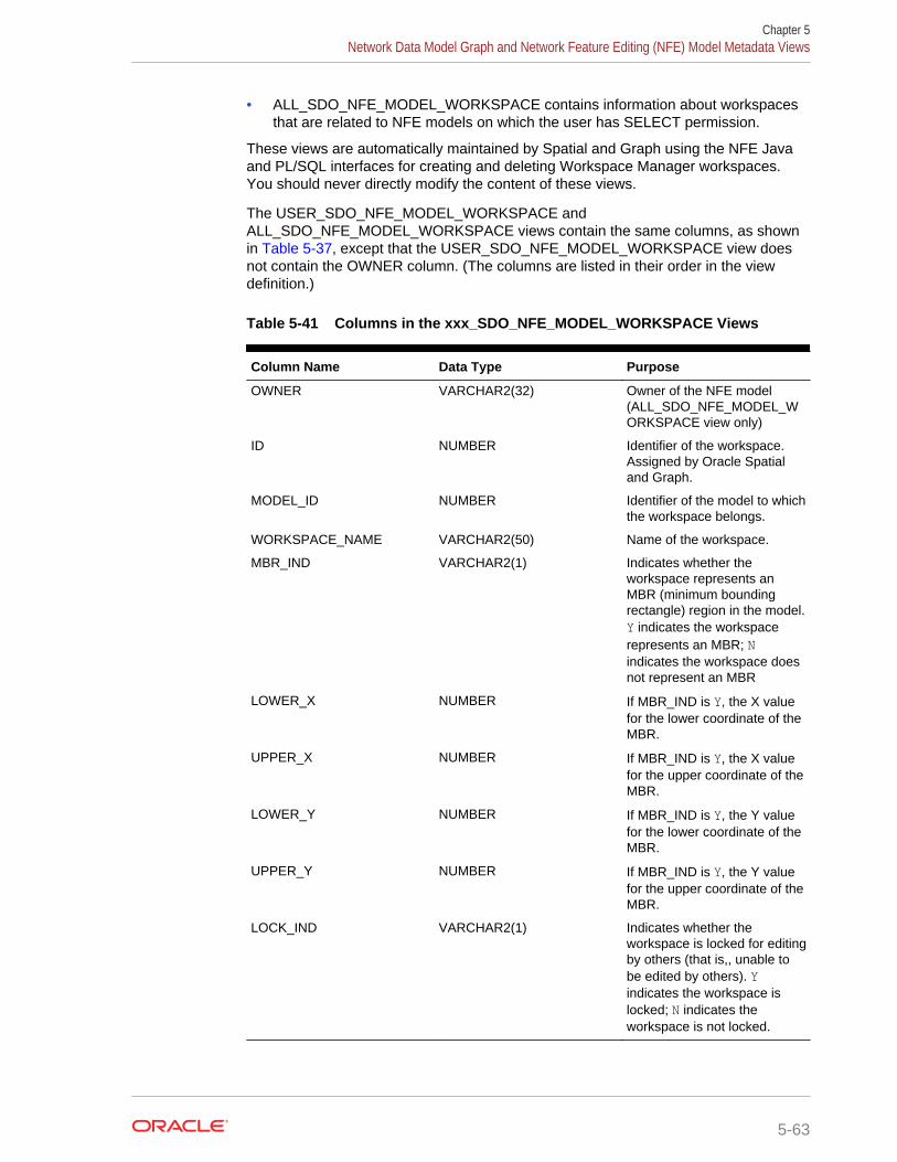
• ALL_SDO_NFE_MODEL_WORKSPACE contains information about workspacesthat are related to NFE models on which the user has SELECT permission.
These views are automatically maintained by Spatial and Graph using the NFE Javaand PL/SQL interfaces for creating and deleting Workspace Manager workspaces.You should never directly modify the content of these views.
The USER_SDO_NFE_MODEL_WORKSPACE andALL_SDO_NFE_MODEL_WORKSPACE views contain the same columns, as shownin Table 5-37, except that the USER_SDO_NFE_MODEL_WORKSPACE view doesnot contain the OWNER column. (The columns are listed in their order in the viewdefinition.)
Table 5-41 Columns in the xxx_SDO_NFE_MODEL_WORKSPACE Views
Column Name Data Type Purpose
OWNER VARCHAR2(32) Owner of the NFE model(ALL_SDO_NFE_MODEL_WORKSPACE view only)
ID NUMBER Identifier of the workspace.Assigned by Oracle Spatialand Graph.
MODEL_ID NUMBER Identifier of the model to whichthe workspace belongs.
WORKSPACE_NAME VARCHAR2(50) Name of the workspace.
MBR_IND VARCHAR2(1) Indicates whether theworkspace represents anMBR (minimum boundingrectangle) region in the model.Y indicates the workspacerepresents an MBR; Nindicates the workspace doesnot represent an MBR
LOWER_X NUMBER If MBR_IND is Y, the X valuefor the lower coordinate of theMBR.
UPPER_X NUMBER If MBR_IND is Y, the X valuefor the upper coordinate of theMBR.
LOWER_Y NUMBER If MBR_IND is Y, the Y valuefor the lower coordinate of theMBR.
UPPER_Y NUMBER If MBR_IND is Y, the Y valuefor the upper coordinate of theMBR.
LOCK_IND VARCHAR2(1) Indicates whether theworkspace is locked for editingby others (that is,, unable tobe edited by others). Yindicates the workspace islocked; N indicates theworkspace is not locked.
Chapter 5Network Data Model Graph and Network Feature Editing (NFE) Model Metadata Views
5-63
5.13 Network Data Model Graph Application ProgrammingInterface
The Oracle Spatial and Graph Network Data Model Graph feature includes two clientapplication programming interfaces (APIs): a PL/SQL interface provided by theSDO_NET package and a Java interface.
Both interfaces let you create and update network data, and the Java interface lets youperform network analysis. It is recommended that you use only PL/SQL or SQL topopulate network tables and to create indexes, and that you mainly use Java forapplication development.
The following performance considerations apply to the PL/SQL and Java APIs:
• If you plan to analyze or edit only nonspatial aspects of a spatial network, you canget better performance by setting the NETWORK_CATEGORY column value toLOGICAL in the USER_SDO_NETWORK_METADATA view (described in xxx_SDO_NETWORK_METADATA Views) before performing the analysis orediting, and then changing the value back to SPATIAL afterward.
For example, you could use this technique when finding the shortest path betweentwo nodes, because the shortest-path computation considers cost values.However, you could not use this technique when setting the spatial geometryobject or the end measure value for a link.
• If you do not plan to modify any network objects (that is, if you plan to perform onlynetwork analysis operations or to retrieve network information), you can get betterperformance by creating the network memory object as read-only (that is, byspecifying that updates are not allowed).
• Network Data Model Graph PL/SQL Interface
• Network Data Model Graph Java Interface
• Network Data Model Graph XML Interface
5.13.1 Network Data Model Graph PL/SQL InterfaceThe SDO_NET package provides subprograms for creating, accessing, and managingnetworks on a database server. Example 5-5 in Network Examples shows the use ofSDO_NET functions and procedures.
The SDO_NET subprograms can be grouped into the following logical categories:
• Creating networks:
SDO_NET.CREATE_SDO_NETWORK
SDO_NET.CREATE_LRS_NETWORK
SDO_NET.CREATE_TOPO_NETWORK
SDO_NET.CREATE_LOGICAL_NETWORK
• Copying and deleting networks:
SDO_NET.COPY_NETWORK
SDO_NET.DROP_NETWORK
Chapter 5Network Data Model Graph Application Programming Interface
5-64

• Creating network tables:
SDO_NET.CREATE_NODE_TABLE
SDO_NET.CREATE_LINK_TABLE
SDO_NET.CREATE_PATH_TABLE
SDO_NET.CREATE_PATH_LINK_TABLE
SDO_NET.CREATE_LRS_TABLE
• Validating network objects:
SDO_NET.VALIDATE_NETWORK
SDO_NET.VALIDATE_NODE_SCHEMA
SDO_NET.VALIDATE_LINK_SCHEMA
SDO_NET.VALIDATE_PATH_SCHEMA
SDO_NET.VALIDATE_LRS_SCHEMA
• Retrieving information (getting information about the network, checking for acharacteristic):
SDO_NET.GET_CHILD_LINKS
SDO_NET.GET_CHILD_NODES
SDO_NET.GET_GEOMETRY_TYPE
SDO_NET.GET_IN_LINKS
SDO_NET.GET_LINK_COST_COLUMN
SDO_NET.GET_LINK_DIRECTION
SDO_NET.GET_LINK_GEOM_COLUMN
SDO_NET.GET_LINK_GEOMETRY
SDO_NET.GET_LINK_TABLE_NAME
SDO_NET.GET_LRS_GEOM_COLUMN
SDO_NET.GET_LRS_LINK_GEOMETRY
SDO_NET.GET_LRS_NODE_GEOMETRY
SDO_NET.GET_LRS_TABLE_NAME
SDO_NET.GET_NETWORK_TYPE
SDO_NET.GET_NO_OF_HIERARCHY_LEVELS
SDO_NET.GET_NO_OF_LINKS
SDO_NET.GET_NO_OF_NODES
SDO_NET.GET_NODE_DEGREE
SDO_NET.GET_NODE_GEOM_COLUMN
SDO_NET.GET_NODE_GEOMETRY
SDO_NET.GET_NODE_IN_DEGREE
SDO_NET.GET_NODE_OUT_DEGREE
SDO_NET.GET_NODE_TABLE_NAME
Chapter 5Network Data Model Graph Application Programming Interface
5-65

SDO_NET.GET_OUT_LINKS
SDO_NET.GET_PATH_GEOM_COLUMN
SDO_NET.GET_PATH_TABLE_NAME
SDO_NET.IS_HIERARCHICAL
SDO_NET.IS_LOGICAL
SDO_NET.IS_SPATIAL
SDO_NET.LRS_GEOMETRY_NETWORK
SDO_NET.NETWORK_EXISTS
SDO_NET.SDO_GEOMETRY_NETWORK
SDO_NET.TOPO_GEOMETRY_NETWORK
For reference information about each SDO_NET function and procedure, see SDO_NET Package Subprograms.
5.13.2 Network Data Model Graph Java InterfaceThe Network Data Model Graph feature includes the load on demand Java interface.Complete reference information about this interface is provided in Oracle Spatial andGraph Java API Reference. The classes of the load on demand Java interface are inthe oracle.spatial.network.lod package and its subpackages.
The Spatial and Graph Java class libraries are in .jar files under the<ORACLE_HOME>/md/jlib/ directory.
• Network Metadata and Data Management
• Network Analysis Using the Load on Demand Approach
5.13.2.1 Network Metadata and Data ManagementYou can use the Java API to perform network metadata and data managementoperations such as the following:
• Insert, delete, and modify node and link data
• Load a network from a database
• Store a network in a database
• Store network metadata in a database
• Modify network metadata attributes
5.13.2.2 Network Analysis Using the Load on Demand ApproachYou can use the oracle.spatial.network.lod.NetworkAnalyst class to performnetwork analysis operations, such as the following, using the load on demandapproach:
• Shortest path: typical transitive closure problems in graph theory. Given a startand an end node, find the shortest path.
• Reachability: Given a node, find all nodes that can reach that node, or find allnodes that can be reached by that node.
Chapter 5Network Data Model Graph Application Programming Interface
5-66

• Within-cost analysis: Given a target node and a cost, find all nodes that can bereached by the target node within the given cost.
• Nearest-neighbors analysis: Given a target node and number of neighbors, findthe neighbor nodes and their costs to go to the given target node.
• Dynamic data input: Create and use a NetworkUpdate object with network updateinformation.
• User-defined link and node cost calculators: Define the method for computing thecost of a link or a node.
5.13.3 Network Data Model Graph XML InterfaceYou can use the Network Data Model Graph XML API to perform network analysis.Web service requests are supported through Oracle Spatial and Graph web services,which are described in Oracle Spatial and Graph Developer's Guide.
HTTP requests can be sent to the web service from Java, PLSQL, or .NET programsor simply from a HTML form. The SDO_NET.POST_XML function (described in SDO_NET Package Subprograms) enables PL/SQL users to call the web service.
The XML schema of the Network Data Model Graph XML API is described in thefollowing: $ORACLE_HOME/md/doc/sdondmxml.zip
• User-Specified Implementations
5.13.3.1 User-Specified ImplementationsThe XML API can take user-specified constraints, cost calculators, or even networkanalysis algorithm settings, by letting you specify the Java class that implements theLOD interfaces. For any implementation that requires input parameters, such as truckweight or height in a trucking constraint implementation, the Java class mustimplement the oracle.spatial.network.lod.XMLConfigurable interface, that is, itmust implement the following two methods:
• void init(Element parameter);
• String getXMLSchema();
The init method lets you pass in the input parameter as an XML element, which mustfollow the schema returned from the getXMLSchema method.
The following XML code segment is an example of how to configure the shortest pathalgorithm for a shortest path analysis request:
<startPoint> <nodeID>123</nodeID></startPoint><endPoint> <nodeID>456</nodeID></endPoint><shortestPathAlgorithm> <className>oracle.spatial.network.lod.AStar</className> <parameters> <heuristicCostFunction> <className>oracle.spatial.network.lod.GeodeticCostFunction</className> <parameters> <userDataCategory>0</userDataCategory> <xCoordUserDataIndex>0</xCoordUserDataIndex>
Chapter 5Network Data Model Graph Application Programming Interface
5-67
<yCoordUserDataIndex>1</yCoordUserDataIndex> </parameters> </heuristicCostFunction> <linkLevelSelector> <className>oracle.spatial.network.lod.DynamicLinkLevelSelector</className> <parameters> <maxLinkLevel>2</maxLinkLevel> <costThreshold linkLevel="1">40000</costThreshold> <numHighLevelNeighbors>8</numHighLevelNeighbors> <costMultiplier>1.5</costMultiplier> <costFunction> <className>oracle.spatial.network.lod.GeodeticCostFunction</className> <parameters> <userDataCategory>0</userDataCategory> <xCoordUserDataIndex>0</xCoordUserDataIndex> <yCoordUserDataIndex>1</yCoordUserDataIndex> </parameters> </costFunction> </parameters> </linkLevelSelector> </parameters></shortestPathAlgorithm>
More examples of the XML API are provided with the NDM tutorial (see Network DataModel Graph Tutorial and Other Resources).
5.14 Cross-Schema Network AccessIf database users other than the network owner need to read a network into memory,you need to do one of the following options.
• For each non-owner user, qualify the network tables with the schema of thenetwork owner in the USER_SDO_NETWORK_METADATA view, as explained in Cross-Schema Access by Specifying Owner in Network Metadata.
• For each non-owner user, create views on the Network Data Model Graph tablesand update the USER_SDO_NETWORK_METADATA view, as explained in Cross-Schema Access by Using Views.
The second approach requires the extra step of creating views, but the views provideyou with flexibility in controlling the parts of the network that are accessible. Each viewcan provide access to all of the network, or it can use a WHERE clause to provideaccess to just one or more parts (for example, WHERE STATE_CODE='NY' to restrict theview users to rows for New York) .
Consider the following example scenario:
• User1 creates (and thus owns) Network1.
• User2 attempts to call theSDO_NET_MEM.NETWORK_MANAGER.READ_NETWORK procedure to readNetwork1, but receives an error. The error occurs even though User2 has theappropriate privileges on the Network Data Model Graph tables for Network1.
To work around this problem, you must use the approach in either Cross-SchemaAccess by Specifying Owner in Network Metadata or Cross-Schema Access by UsingViews.
• Cross-Schema Access by Specifying Owner in Network Metadata
Chapter 5Cross-Schema Network Access
5-68

• Cross-Schema Access by Using Views
5.14.1 Cross-Schema Access by Specifying Owner in NetworkMetadata
To enable a non-owner user (with suitable privileges) to access a network, you canspecify the network owner in the network metadata. For each non-owner user that willbe permitted to access the network, follow these steps:
1. Ensure that the user has SELECT or READ privilege access to the necessaryNetwork Data Model Graph tables. If the user does not have this access, connectas the network owner and grant it. For example, connect as User1 and executethe following statements:
GRANT select ON network1_node$ TO user2;GRANT select ON network1_link$ TO user2;GRANT select ON network1_path$ TO user2;GRANT select ON network1_plink$ TO user2;
2. Connect as the non-owner user. For example, connect as User2.
3. Use the schema name of the network owner to qualify the Network Data ModelGraph tables for the network in the USER_SDO_NETWORK_METADATA view(explained in xxx_SDO_NETWORK_METADATA Views). For example, if thenetwork is not already defined in this view, enter the following while connected asUser2:
INSERT INTO user_sdo_network_metadata (network, network_category, geometry_type, node_table_name,node_geom_column, link_table_name, link_geom_column, link_direction, path_table_name, path_geom_column, path_link_table_name)VALUES ('NETWORK1','SPATIAL', 'SDO_GEOMETRY', 'USER1.NETWORK1_NODE$', 'GEOMETRY', 'USER1.NETWORK1_LINK$', 'GEOMETRY', 'DIRECTED', 'USER1.NETWORK1_PATH$', 'GEOMETRY', 'USER1.NETWORK1_PLINK$');
If the network is already defined in this view, update the definition to qualify eachtable name with the schema name. For example:
UPDATE USER_SDO_NETWORK_METADATA SET node_table_name = 'USER1.NETWORK1_NODE$', link_table_name = 'USER1.NETWORK1_LINK$', path_table_name = 'USER1.NETWORK1_PATH$', path_link_table_name = 'USER1.NETWORK1_PLINK$' WHERE network = 'NETWORK1';
In this scenario, User2 can now read NETWORK1 into memory.
5.14.2 Cross-Schema Access by Using ViewsTo enable a non-owner user (with suitable privileges) to access a network, or specificparts of a network, you can create views. For each non-owner user that will bepermitted to access the network, follow these steps:
Chapter 5Cross-Schema Network Access
5-69
1. Ensure that the user has SELECT or READ privilege access to the necessaryNetwork Data Model Graph tables. If the user does not have this access, connectas the network owner and grant it. For example, connect as User1 and executethe following statements:
GRANT select ON network1_node$ TO user2;GRANT select ON network1_link$ TO user2;GRANT select ON network1_path$ TO user2;GRANT select ON network1_plink$ TO user2;
2. Connect as the non-owner user. For example, connect as User2.
3. Create a view on each of the necessary Network Data Model Graph nodes, witheach view selecting all columns in the associated table. Qualify the table namewith the schema name of the network owner. For example, while connected asUser2:
CREATE VIEW network1_node$ AS select * from user1.network1_node$;CREATE VIEW network1_link$ AS select * from user1.network1_link$;CREATE VIEW network1_path$ AS select * from user1.network1_path$;CREATE VIEW network1_plink$ AS select * from user1.network1_plink$;
Note:
Although this example shows views that include all data in the underlyingtables, you can restrict the parts of the network that are available byusing a WHERE clause in each view definition (for example, WHERESTATE_CODE='NY').
4. Add a row specifying the newly created views to theUSER_SDO_NETWORK_METADATA view (explained in xxx_SDO_NETWORK_METADATA Views). For example, while connected asUser2:
INSERT INTO user_sdo_network_metadata (network, network_category, geometry_type, node_table_name,node_geom_column, link_table_name, link_geom_column, link_direction, path_table_name, path_geom_column, path_link_table_name)VALUES ('NETWORK1','SPATIAL', 'SDO_GEOMETRY', 'NETWORK1_NODE$', 'GEOMETRY', 'NETWORK1_LINK$', 'GEOMETRY', 'DIRECTED', 'NETWORK1_PATH$', 'GEOMETRY', 'NETWORK1_PLINK$');
In this scenario, User2 can now read into memory those parts of NETWORK1 that areavailable through the views that were created.
5.15 Network ExamplesThis topic presents several Network Data Model Graph examples.
Most are simplified examples. All examples use the PL/SQL API, and some also useother APIs.
Chapter 5Network Examples
5-70

The examples refer to concepts that are explained in this chapter, and they usePL/SQL functions and procedures documented in SDO_NET Package Subprograms.
• Simple Spatial (SDO) Network Example (PL/SQL)
• Simple Logical Network Example (PL/SQL)
• Spatial (LRS) Network Example (PL/SQL)
• Logical Hierarchical Network Example (PL/SQL)
• Partitioning and Load on Demand Analysis Examples (PL/SQL, XML, and Java)
• User-Defined Data Examples (PL/SQL and Java)
5.15.1 Simple Spatial (SDO) Network Example (PL/SQL)This section presents an example of a very simple spatial (SDO, not LRS) network thatcontains three nodes and a link between each node. The network is illustrated in Figure 5-4.
Figure 5-4 Simple Spatial (SDO) Network
0 1 2 3 4 5 6 7 8 9 10 11 12 13 14 15
1
2
3
4
5
N1 N2L1
L3 L2
N3
As shown in Figure 5-4, node N1 is at point 1,1, node N2 is at point 15,1, and node N3is at point 9,4. Link L1 is a straight line connecting nodes N1 and N2, link L2 is a straightline connecting nodes N2 and N3, and link L3 is a straight line connecting nodes N3 andN1. There are no other nodes or shape points on any of the links.
Example 5-3 does the following:
• In a call to the SDO_NET.CREATE_SDO_NETWORK procedure, creates theSDO_NET1 directed network; creates the SDO_NET1_NODE$, SDO_NET1_LINK$,SDO_NET1_PATH$, and SDO_NET1_PLINK$ tables; and updates thexxx_SDO_NETWORK_METADATA views. All geometry columns are namedGEOMETRY. Both the node and link tables contain a cost column named COST.
• Populates the node, link, path, and path-link tables. It inserts three rows into thenode table, three rows into the link table, two rows into the path table, and fourrows into the path-link table.
• Updates the Oracle Spatial and Graph metadata, and creates spatial indexes onthe GEOMETRY columns of the node and link tables. (These actions are notspecifically related to network management, but that are necessary if applicationsare to benefit from spatial indexing on these geometry columns.)
Example 5-3 does not show the use of many SDO_NET functions and procedures;these are included in Example 5-5 in Spatial (LRS) Network Example (PL/SQL).
Chapter 5Network Examples
5-71

Example 5-3 Simple Spatial (SDO) Network Example (PL/SQL)
-- Create the SDO_NET1 directed network. Also creates the SDO_NET1_NODE$, -- SDO_NET1_LINK$, SDO_NET1_PATH$, SDO_NET1_PLINK$ tables, and updates -- USER_SDO_NETWORK_METADATA. All geometry columns are named GEOMETRY. -- Both the node and link tables contain a cost column named COST. EXECUTE SDO_NET.CREATE_SDO_NETWORK('SDO_NET1', 1, TRUE, TRUE); -- Populate the SDO_NET1_NODE$ table.-- N1INSERT INTO sdo_net1_node$ (node_id, node_name, active, geometry, cost) VALUES(1, 'N1', 'Y', SDO_GEOMETRY(2001, NULL, SDO_POINT_TYPE(1,1,NULL), NULL, NULL), 5);-- N2INSERT INTO sdo_net1_node$ (node_id, node_name, active, geometry, cost) VALUES(2, 'N2', 'Y', SDO_GEOMETRY(2001, NULL, SDO_POINT_TYPE(15,1,NULL), NULL, NULL), 8);-- N3INSERT INTO sdo_net1_node$ (node_id, node_name, active, geometry, cost) VALUES(3, 'N3', 'Y', SDO_GEOMETRY(2001, NULL, SDO_POINT_TYPE(9,4,NULL), NULL, NULL), 4); -- Populate the SDO_NET1_LINK$ table.-- L1INSERT INTO sdo_net1_link$ (link_id, link_name, start_node_id, end_node_id, active, geometry, cost, bidirected) VALUES(1, 'L1', 1, 2, 'Y', SDO_GEOMETRY(2002, NULL, NULL, SDO_ELEM_INFO_ARRAY(1,2,1), SDO_ORDINATE_ARRAY(1,1, 15,1)), 14, 'Y');-- L2INSERT INTO sdo_net1_link$ (link_id, link_name, start_node_id, end_node_id, active, geometry, cost, bidirected) VALUES(2, 'L2', 2, 3, 'Y', SDO_GEOMETRY(2002, NULL, NULL, SDO_ELEM_INFO_ARRAY(1,2,1), SDO_ORDINATE_ARRAY(15,1, 9,4)), 10, 'Y');-- L3INSERT INTO sdo_net1_link$ (link_id, link_name, start_node_id, end_node_id, active, geometry, cost, bidirected) VALUES(3, 'L3', 3, 1, 'Y', SDO_GEOMETRY(2002, NULL, NULL, SDO_ELEM_INFO_ARRAY(1,2,1), SDO_ORDINATE_ARRAY(9,4, 1,1)), 10, 'Y'); -- Do not populate the SDO_NET1_PATH$ and SDO_NET1_PLINK$ tables now.-- Do this only when you need to create any paths. ----------------------------------------------------------------------------- REMAINING STEPS NEEDED TO USE SPATIAL INDEXES ------------------------------------------------------------------------------- Update the USER_SDO_GEOM_METADATA view. This is required before the-- spatial index can be created. Do this only once for each layer-- (that is, table-column combination).
Chapter 5Network Examples
5-72
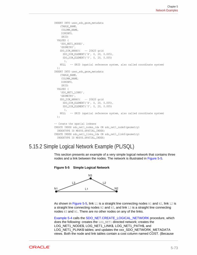
INSERT INTO user_sdo_geom_metadata (TABLE_NAME, COLUMN_NAME, DIMINFO, SRID) VALUES ( 'SDO_NET1_NODE$', 'GEOMETRY', SDO_DIM_ARRAY( -- 20X20 grid SDO_DIM_ELEMENT('X', 0, 20, 0.005), SDO_DIM_ELEMENT('Y', 0, 20, 0.005) ), NULL -- SRID (spatial reference system, also called coordinate system) );INSERT INTO user_sdo_geom_metadata (TABLE_NAME, COLUMN_NAME, DIMINFO, SRID) VALUES ( 'SDO_NET1_LINK$', 'GEOMETRY', SDO_DIM_ARRAY( -- 20X20 grid SDO_DIM_ELEMENT('X', 0, 20, 0.005), SDO_DIM_ELEMENT('Y', 0, 20, 0.005) ), NULL -- SRID (spatial reference system, also called coordinate system) ); -- Create the spatial indexesCREATE INDEX sdo_net1_nodes_idx ON sdo_net1_node$(geometry) INDEXTYPE IS MDSYS.SPATIAL_INDEX;CREATE INDEX sdo_net1_links_idx ON sdo_net1_link$(geometry) INDEXTYPE IS MDSYS.SPATIAL_INDEX;
5.15.2 Simple Logical Network Example (PL/SQL)This section presents an example of a very simple logical network that contains threenodes and a link between the nodes. The network is illustrated in Figure 5-5.
Figure 5-5 Simple Logical Network
N1 N2L1
L3 L2
N3
As shown in Figure 5-5, link L1 is a straight line connecting nodes N1 and N2, link L2 isa straight line connecting nodes N2 and N3, and link L3 is a straight line connectingnodes N3 and N1. There are no other nodes on any of the links.
Example 5-4 calls the SDO_NET.CREATE_LOGICAL_NETWORK procedure, whichdoes the following: creates the LOG_NET1 directed network; creates theLOG_NET1_NODE$, LOG_NET1_LINK$, LOG_NET1_PATH$, andLOG_NET1_PLINK$ tables; and updates the xxx_SDO_NETWORK_METADATAviews. Both the node and link tables contain a cost column named COST. (Because
Chapter 5Network Examples
5-73
this is a logical network, there are no geometry columns.) The example also populatesthe node and link tables.
Example 5-4 does not show the use of many SDO_NET functions and procedures;these are included in the logical hierarchical network example (Example 5-6) in LogicalHierarchical Network Example (PL/SQL).
Example 5-4 Simple Logical Network Example (PL/SQL)
-- Creates the LOG_NET1 directed logical network. Also creates the-- LOG_NET1_NODE$, LOG_NET1_LINK$, LOG_NET1_PATH$,-- and LOG_NET1_PLINK$ tables, and updates USER_SDO_NETWORK_METADATA.-- Both the node and link tables contain a cost column named COST. EXECUTE SDO_NET.CREATE_LOGICAL_NETWORK('LOG_NET1', 1, TRUE, TRUE); -- Populate the LOG_NET1_NODE$ table.-- N1INSERT INTO log_net1_node$ (node_id, node_name, active, cost) VALUES (1, 'N1', 'Y', 2);-- N2INSERT INTO log_net1_node$ (node_id, node_name, active, cost) VALUES (2, 'N2', 'Y', 3);-- N3INSERT INTO log_net1_node$ (node_id, node_name, active, cost) VALUES (3, 'N3', 'Y', 2); -- Populate the LOG_NET1_LINK$ table.-- L1INSERT INTO log_net1_link$ (link_id, link_name, start_node_id, end_node_id, active, link_level, cost) VALUES (1, 'L1', 1, 2, 'Y', 1, 10);-- L2INSERT INTO log_net1_link$ (link_id, link_name, start_node_id, end_node_id, active, link_level, cost) VALUES (2, 'L2', 2, 3, 'Y', 1, 7);-- L3INSERT INTO log_net1_link$ (link_id, link_name, start_node_id, end_node_id, active, link_level, cost) VALUES (3, 'L3', 3, 1, 'Y', 1, 8); -- Do not populate the LOG_NET1_PATH$ and LOG_NET1_PLINK$ tables now.-- Do this only when you need to create any paths.
5.15.3 Spatial (LRS) Network Example (PL/SQL)This section presents an example of a spatial (LRS) network that uses the roads(routes) illustrated in Figure 5-6. Each road is built from individual line segments(associated with links) taken from one or more road segment geometries, which arealso shown in the figure.
Chapter 5Network Examples
5-74
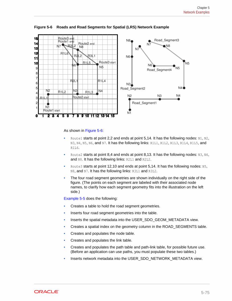
Figure 5-6 Roads and Road Segments for Spatial (LRS) Network Example
0 1 2 3 4 5 6 7 8 9 10 11 12 13 14 15
1
2
3
4
5
6
7
8
9
10
11
12
13
14
15
Route1 start
Route1 end
N1
N2 N3 N4
N5
N8
N6
N7
Route2 start
Route2 end
Route3 start
Route3 end
R1L5
R1L6
R1L4
R1L3R1L2
R1L1
R2L2
R2L1
R3L2
R3L1
Road_Segment1
Road_Segment2
Road_Segment3
Road_Segment4
N1
N2 N3 N4
N3
N6
N8
N7
N7
N6N5
N5
N8
N4
As shown in Figure 5-6:
• Route1 starts at point 2,2 and ends at point 5,14. It has the following nodes: N1, N2,N3, N4, N5, N6, and N7. It has the following links: R1L1, R1L2, R1L3, R1L4, R1L5, andR1L6.
• Route2 starts at point 8,4 and ends at point 8,13. It has the following nodes: N3, N6,and N8. It has the following links: R2L1 and R2L2.
• Route3 starts at point 12,10 and ends at point 5,14. It has the following nodes: N5,N8, and N7. It has the following links: R3L1 and R3L2.
• The four road segment geometries are shown individually on the right side of thefigure. (The points on each segment are labeled with their associated nodenames, to clarify how each segment geometry fits into the illustration on the leftside.)
Example 5-5 does the following:
• Creates a table to hold the road segment geometries.
• Inserts four road segment geometries into the table.
• Inserts the spatial metadata into the USER_SDO_GEOM_METADATA view.
• Creates a spatial index on the geometry column in the ROAD_SEGMENTS table.
• Creates and populates the node table.
• Creates and populates the link table.
• Creates and populates the path table and path-link table, for possible future use.(Before an application can use paths, you must populate these two tables.)
• Inserts network metadata into the USER_SDO_NETWORK_METADATA view.
Chapter 5Network Examples
5-75
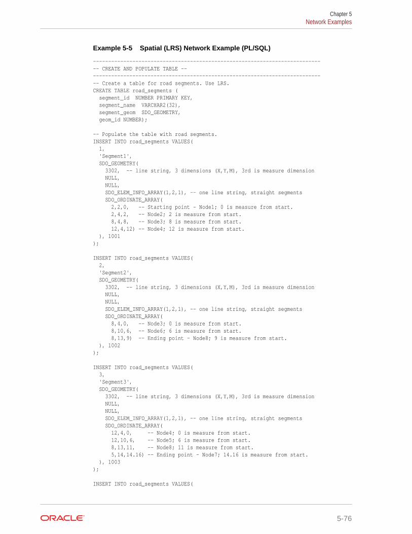
Example 5-5 Spatial (LRS) Network Example (PL/SQL)
----------------------------------------------------------------------------- CREATE AND POPULATE TABLE ------------------------------------------------------------------------------- Create a table for road segments. Use LRS.CREATE TABLE road_segments ( segment_id NUMBER PRIMARY KEY, segment_name VARCHAR2(32), segment_geom SDO_GEOMETRY, geom_id NUMBER); -- Populate the table with road segments.INSERT INTO road_segments VALUES( 1, 'Segment1', SDO_GEOMETRY( 3302, -- line string, 3 dimensions (X,Y,M), 3rd is measure dimension NULL, NULL, SDO_ELEM_INFO_ARRAY(1,2,1), -- one line string, straight segments SDO_ORDINATE_ARRAY( 2,2,0, -- Starting point - Node1; 0 is measure from start. 2,4,2, -- Node2; 2 is measure from start. 8,4,8, -- Node3; 8 is measure from start. 12,4,12) -- Node4; 12 is measure from start. ), 1001); INSERT INTO road_segments VALUES( 2, 'Segment2', SDO_GEOMETRY( 3302, -- line string, 3 dimensions (X,Y,M), 3rd is measure dimension NULL, NULL, SDO_ELEM_INFO_ARRAY(1,2,1), -- one line string, straight segments SDO_ORDINATE_ARRAY( 8,4,0, -- Node3; 0 is measure from start. 8,10,6, -- Node6; 6 is measure from start. 8,13,9) -- Ending point - Node8; 9 is measure from start. ), 1002); INSERT INTO road_segments VALUES( 3, 'Segment3', SDO_GEOMETRY( 3302, -- line string, 3 dimensions (X,Y,M), 3rd is measure dimension NULL, NULL, SDO_ELEM_INFO_ARRAY(1,2,1), -- one line string, straight segments SDO_ORDINATE_ARRAY( 12,4,0, -- Node4; 0 is measure from start. 12,10,6, -- Node5; 6 is measure from start. 8,13,11, -- Node8; 11 is measure from start. 5,14,14.16) -- Ending point - Node7; 14.16 is measure from start. ), 1003); INSERT INTO road_segments VALUES(
Chapter 5Network Examples
5-76
4, 'Segment4', SDO_GEOMETRY( 3302, -- line string, 3 dimensions (X,Y,M), 3rd is measure dimension NULL, NULL, SDO_ELEM_INFO_ARRAY(1,2,1), -- one line string, straight segments SDO_ORDINATE_ARRAY( 12,10,0, -- Node5; 0 is measure from start. 8,10,4, -- Node6; 4 is measure from start. 5,14,9) -- Ending point - Node7; 9 is measure from start. ), 1004); ----------------------------------------------------------------------------- UPDATE THE SPATIAL METADATA ------------------------------------------------------------------------------- Update the USER_SDO_GEOM_METADATA view. This is required before the-- spatial index can be created. Do this only once for each layer-- (that is, table-column combination; here: road_segment and segment_geom).INSERT INTO user_sdo_geom_metadata (TABLE_NAME, COLUMN_NAME, DIMINFO, SRID) VALUES ( 'ROAD_SEGMENTS', 'SEGMENT_GEOM', SDO_DIM_ARRAY( -- 20X20 grid SDO_DIM_ELEMENT('X', 0, 20, 0.005), SDO_DIM_ELEMENT('Y', 0, 20, 0.005), SDO_DIM_ELEMENT('M', 0, 20, 0.005) -- Measure dimension ), NULL -- SRID (spatial reference system, also called coordinate system)); --------------------------------------------------------------------- CREATE THE SPATIAL INDEX ---------------------------------------------------------------------CREATE INDEX road_segments_idx ON road_segments(segment_geom) INDEXTYPE IS MDSYS.SPATIAL_INDEX; ---------------------------------- USE SDO_NET SUBPROGRAMS-------------------------------- -- This procedure does not use the CREATE_LRS_NETWORK procedure. Instead,-- the user creates the network tables and populates the network metadata view.-- Basic steps:-- 1. Create and populate the node table.-- 2. Create and populate the link table.-- 3. Create the path table and paths and links table (for possible -- future use, before which they will need to be populated).-- 4. Populate the network metadata (USER_SDO_NETWORK_METADATA).-- Note: Can be done before or after Steps 1-3.-- 5. Use various SDO_NET functions and procedures. -- 1. Create and populate the node table.EXECUTE SDO_NET.CREATE_NODE_TABLE('ROADS_NODES', 'LRS_GEOMETRY', 'NODE_GEOMETRY', 'COST', 1);
Chapter 5Network Examples
5-77
-- Populate the node table. -- N1INSERT INTO roads_nodes (node_id, node_name, active, geom_id, measure) VALUES (1, 'N1', 'Y', 1001, 0); -- N2INSERT INTO roads_nodes (node_id, node_name, active, geom_id, measure) VALUES (2, 'N2', 'Y', 1001, 2); -- N3INSERT INTO roads_nodes (node_id, node_name, active, geom_id, measure) VALUES (3, 'N3', 'Y', 1001, 8); -- N4INSERT INTO roads_nodes (node_id, node_name, active, geom_id, measure) VALUES (4, 'N4', 'Y', 1001, 12); -- N5INSERT INTO roads_nodes (node_id, node_name, active, geom_id, measure) VALUES (5, 'N5', 'Y', 1004, 0); -- N6INSERT INTO roads_nodes (node_id, node_name, active, geom_id, measure) VALUES (6, 'N6', 'Y', 1002, 6); -- N7INSERT INTO roads_nodes (node_id, node_name, active, geom_id, measure) VALUES (7, 'N7', 'Y', 1004, 9); -- N8INSERT INTO roads_nodes (node_id, node_name, active, geom_id, measure) VALUES (8, 'N8', 'Y', 1002, 9); -- 2. Create and populate the link table.EXECUTE SDO_NET.CREATE_LINK_TABLE('ROADS_LINKS', 'LRS_GEOMETRY', 'LINK_GEOMETRY', 'COST', 1); -- Populate the link table. -- Route1, Link1INSERT INTO roads_links (link_id, link_name, start_node_id, end_node_id, active, cost, geom_id, start_measure, end_measure)VALUES (101, 'R1L1', 1, 2, 'Y', 3, 1001, 0, 2); -- Route1, Link2INSERT INTO roads_links (link_id, link_name, start_node_id, end_node_id, active, cost, geom_id, start_measure, end_measure)VALUES (102, 'R1L2', 2, 3, 'Y', 15, 1001, 2, 8); -- Route1, Link3INSERT INTO roads_links (link_id, link_name, start_node_id, end_node_id, active, cost, geom_id, start_measure, end_measure)VALUES (103, 'R1L3', 3, 4, 'Y', 10, 1001, 8, 12); -- Route1, Link4INSERT INTO roads_links (link_id, link_name, start_node_id, end_node_id, active, cost, geom_id, start_measure, end_measure)VALUES (104, 'R1L4', 4, 5, 'Y', 15, 1003, 0, 6); -- Route1, Link5
Chapter 5Network Examples
5-78
INSERT INTO roads_links (link_id, link_name, start_node_id, end_node_id, active, cost, geom_id, start_measure, end_measure)VALUES (105, 'R1L5', 5, 6, 'Y', 10, 1004, 0, 4); -- Route1, Link6INSERT INTO roads_links (link_id, link_name, start_node_id, end_node_id, active, cost, geom_id, start_measure, end_measure)VALUES (106, 'R1L6', 6, 7, 'Y', 7, 1004, 4, 9); -- Route2, Link1 (cost = 30, a slow drive)INSERT INTO roads_links (link_id, link_name, start_node_id, end_node_id, active, cost, geom_id, start_measure, end_measure)VALUES (201, 'R2L1', 3, 6, 'Y', 30, 1002, 0, 6); -- Route2, Link2INSERT INTO roads_links (link_id, link_name, start_node_id, end_node_id, active, cost, geom_id, start_measure, end_measure)VALUES (202, 'R2L2', 6, 8, 'Y', 5, 1002, 6, 9); -- Route3, Link1INSERT INTO roads_links (link_id, link_name, start_node_id, end_node_id, active, cost, geom_id, start_measure, end_measure)VALUES (301, 'R3L1', 5, 8, 'Y', 5, 1003, 6, 11); -- Route3, Link2INSERT INTO roads_links (link_id, link_name, start_node_id, end_node_id, active, cost, geom_id, start_measure, end_measure)VALUES (302, 'R3L2', 8, 7, 'Y', 5, 1003, 11, 14.16); -- 3. Create the path table (to store created paths) and the path-link -- table (to store links for each path) for possible future use,-- before which they will need to be populated.EXECUTE SDO_NET.CREATE_PATH_TABLE('ROADS_PATHS', 'PATH_GEOMETRY');EXECUTE SDO_NET.CREATE_PATH_LINK_TABLE('ROADS_PATHS_LINKS'); -- 4. Populate the network metadata (USER_SDO_NETWORK_METADATA). INSERT INTO user_sdo_network_metadata (NETWORK, NETWORK_CATEGORY, GEOMETRY_TYPE, NETWORK_TYPE, NO_OF_HIERARCHY_LEVELS, NO_OF_PARTITIONS, LRS_TABLE_NAME, LRS_GEOM_COLUMN, NODE_TABLE_NAME, NODE_GEOM_COLUMN, NODE_COST_COLUMN, LINK_TABLE_NAME, LINK_GEOM_COLUMN, LINK_DIRECTION, LINK_COST_COLUMN, PATH_TABLE_NAME, PATH_GEOM_COLUMN, PATH_LINK_TABLE_NAME) VALUES ( 'ROADS_NETWORK', -- Network name 'SPATIAL', -- Network category 'LRS_GEOMETRY', -- Geometry type 'Roadways', -- Network type (user-defined)
Chapter 5Network Examples
5-79
1, -- No. of levels in hierarchy 1, -- No. of partitions 'ROAD_SEGMENTS', -- LRS table name 'SEGMENT_GEOM' , -- LRS geometry column 'ROADS_NODES', -- Node table name 'NODE_GEOMETRY', -- Node geometry column 'COST', -- Node cost column 'ROADS_LINKS', -- Link table name 'LINK_GEOMETRY', -- Link geometry column 'DIRECTED', -- Link direction 'COST', -- Link cost column 'ROADS_PATHS', -- Path table name 'PATH_GEOMETRY', -- Path geometry column 'ROADS_PATHS_LINKS' -- Paths and links table ); -- 5. Use various SDO_NET functions and procedures. -- Validate the network.SELECT SDO_NET.VALIDATE_NETWORK('ROADS_NETWORK') FROM DUAL; -- Validate parts or aspects of the network.SELECT SDO_NET.VALIDATE_LINK_SCHEMA('ROADS_NETWORK') FROM DUAL;SELECT SDO_NET.VALIDATE_LRS_SCHEMA('ROADS_NETWORK') FROM DUAL;SELECT SDO_NET.VALIDATE_NODE_SCHEMA('ROADS_NETWORK') FROM DUAL;SELECT SDO_NET.VALIDATE_PATH_SCHEMA('ROADS_NETWORK') FROM DUAL; -- Retrieve various information (GET_xxx and some other functions).SELECT SDO_NET.GET_CHILD_LINKS('ROADS_NETWORK', 101) FROM DUAL;SELECT SDO_NET.GET_CHILD_NODES('ROADS_NETWORK', 1) FROM DUAL;SELECT SDO_NET.GET_GEOMETRY_TYPE('ROADS_NETWORK') FROM DUAL;SELECT SDO_NET.GET_IN_LINKS('ROADS_NETWORK', 3) FROM DUAL;SELECT SDO_NET.GET_INVALID_LINKS('ROADS_NETWORK') FROM DUAL;SELECT SDO_NET.GET_INVALID_NODES('ROADS_NETWORK') FROM DUAL;SELECT SDO_NET.GET_INVALID_PATHS('ROADS_NETWORK') FROM DUAL;SELECT SDO_NET.GET_ISOLATED_NODES('ROADS_NETWORK') FROM DUAL;SELECT SDO_NET.GET_LINK_COST_COLUMN('ROADS_NETWORK') FROM DUAL;SELECT SDO_NET.GET_LINK_DIRECTION('ROADS_NETWORK') FROM DUAL;SELECT SDO_NET.GET_LINK_GEOM_COLUMN('ROADS_NETWORK') FROM DUAL;SELECT SDO_NET.GET_LINK_GEOMETRY('ROADS_NETWORK', 103) FROM DUAL;SELECT SDO_NET.GET_LINK_TABLE_NAME('ROADS_NETWORK') FROM DUAL;SELECT SDO_NET.GET_LRS_GEOM_COLUMN('ROADS_NETWORK') FROM DUAL;SELECT SDO_NET.GET_LRS_LINK_GEOMETRY('ROADS_NETWORK', 103) FROM DUAL;SELECT SDO_NET.GET_LRS_NODE_GEOMETRY('ROADS_NETWORK', 3) FROM DUAL;SELECT SDO_NET.GET_LRS_TABLE_NAME('ROADS_NETWORK') FROM DUAL;SELECT SDO_NET.GET_NETWORK_CATEGORY('ROADS_NETWORK') FROM DUAL;SELECT SDO_NET.GET_NETWORK_ID('ROADS_NETWORK') FROM DUAL;SELECT SDO_NET.GET_NETWORK_NAME(3) FROM DUAL;SELECT SDO_NET.GET_NETWORK_TYPE('ROADS_NETWORK') FROM DUAL;SELECT SDO_NET.GET_NO_OF_HIERARCHY_LEVELS('ROADS_NETWORK') FROM DUAL;SELECT SDO_NET.GET_NO_OF_LINKS('ROADS_NETWORK') FROM DUAL;SELECT SDO_NET.GET_NO_OF_NODES('ROADS_NETWORK') FROM DUAL;SELECT SDO_NET.GET_NODE_DEGREE('ROADS_NETWORK', 3) FROM DUAL;SELECT SDO_NET.GET_NODE_GEOM_COLUMN('ROADS_NETWORK') FROM DUAL;SELECT SDO_NET.GET_NODE_GEOMETRY('ROADS_NETWORK', 3) FROM DUAL;SELECT SDO_NET.GET_NODE_IN_DEGREE('ROADS_NETWORK', 3) FROM DUAL;SELECT SDO_NET.GET_NODE_OUT_DEGREE('ROADS_NETWORK', 3) FROM DUAL;SELECT SDO_NET.GET_NODE_TABLE_NAME('ROADS_NETWORK') FROM DUAL;SELECT SDO_NET.GET_NODE_COST_COLUMN('ROADS_NETWORK') FROM DUAL;SELECT SDO_NET.GET_NODE_HIERARCHY_LEVEL('ROADS_NETWORK', 3) FROM DUAL;SELECT SDO_NET.GET_OUT_LINKS('ROADS_NETWORK', 3) FROM DUAL;
Chapter 5Network Examples
5-80
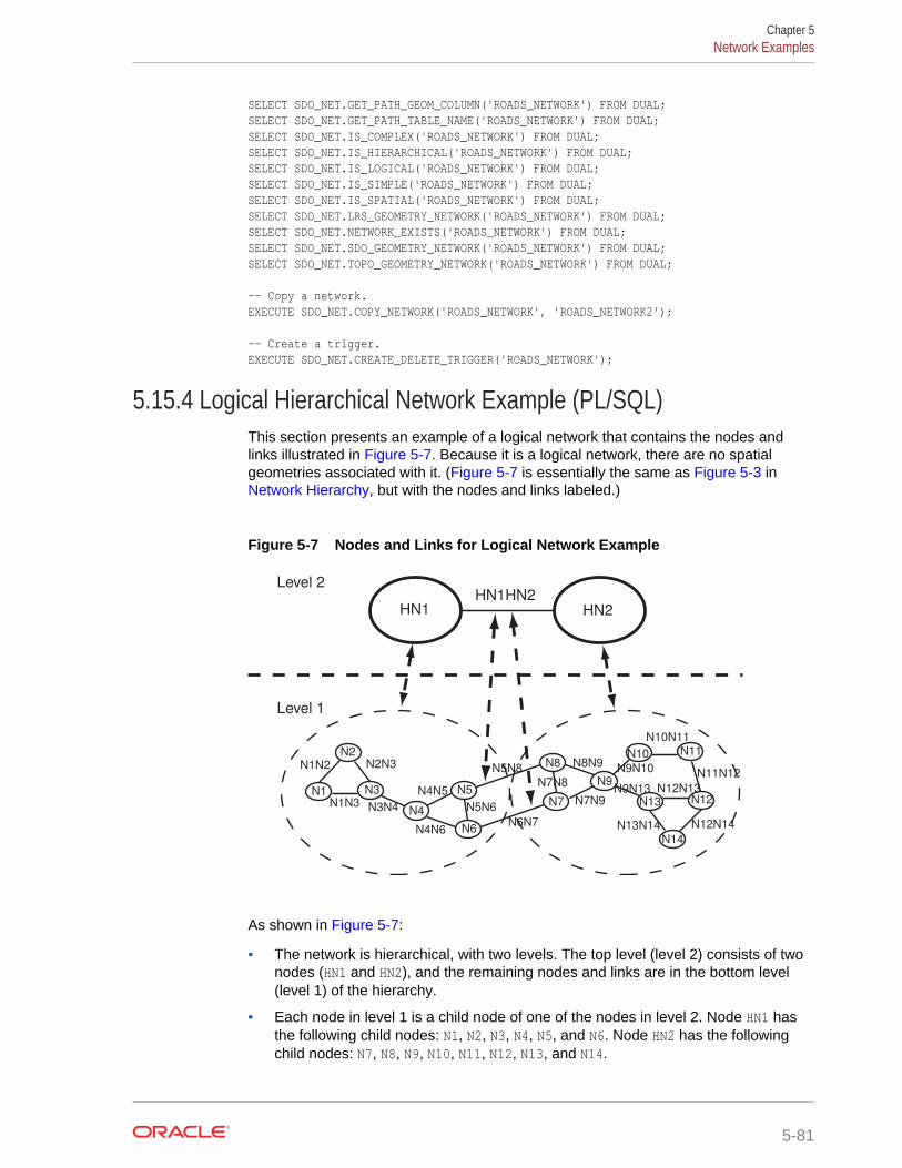
SELECT SDO_NET.GET_PATH_GEOM_COLUMN('ROADS_NETWORK') FROM DUAL;SELECT SDO_NET.GET_PATH_TABLE_NAME('ROADS_NETWORK') FROM DUAL;SELECT SDO_NET.IS_COMPLEX('ROADS_NETWORK') FROM DUAL;SELECT SDO_NET.IS_HIERARCHICAL('ROADS_NETWORK') FROM DUAL;SELECT SDO_NET.IS_LOGICAL('ROADS_NETWORK') FROM DUAL;SELECT SDO_NET.IS_SIMPLE('ROADS_NETWORK') FROM DUAL;SELECT SDO_NET.IS_SPATIAL('ROADS_NETWORK') FROM DUAL;SELECT SDO_NET.LRS_GEOMETRY_NETWORK('ROADS_NETWORK') FROM DUAL;SELECT SDO_NET.NETWORK_EXISTS('ROADS_NETWORK') FROM DUAL;SELECT SDO_NET.SDO_GEOMETRY_NETWORK('ROADS_NETWORK') FROM DUAL;SELECT SDO_NET.TOPO_GEOMETRY_NETWORK('ROADS_NETWORK') FROM DUAL; -- Copy a network.EXECUTE SDO_NET.COPY_NETWORK('ROADS_NETWORK', 'ROADS_NETWORK2'); -- Create a trigger.EXECUTE SDO_NET.CREATE_DELETE_TRIGGER('ROADS_NETWORK');
5.15.4 Logical Hierarchical Network Example (PL/SQL)This section presents an example of a logical network that contains the nodes andlinks illustrated in Figure 5-7. Because it is a logical network, there are no spatialgeometries associated with it. (Figure 5-7 is essentially the same as Figure 5-3 in Network Hierarchy, but with the nodes and links labeled.)
Figure 5-7 Nodes and Links for Logical Network Example
Level 2
Level 1
N2
N1 N3
N4
N5
N6
N8
N7
N9
N10 N11
N12N13
N14
HN1 HN2
HN1HN2
N1N2 N2N3
N1N3 N3N4
N4N5
N4N6
N5N6
N5N8
N6N7
N9N10
N9N13
N8N9
N7N9
N12N14
N10N11
N13N14
N12N13
N11N12N7N8
As shown in Figure 5-7:
• The network is hierarchical, with two levels. The top level (level 2) consists of twonodes (HN1 and HN2), and the remaining nodes and links are in the bottom level(level 1) of the hierarchy.
• Each node in level 1 is a child node of one of the nodes in level 2. Node HN1 hasthe following child nodes: N1, N2, N3, N4, N5, and N6. Node HN2 has the followingchild nodes: N7, N8, N9, N10, N11, N12, N13, and N14.
Chapter 5Network Examples
5-81
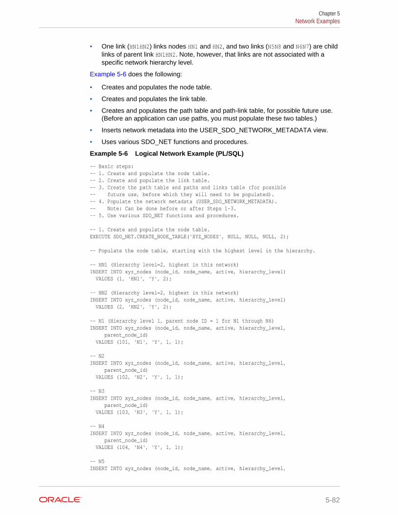
• One link (HN1HN2) links nodes HN1 and HN2, and two links (N5N8 and N6N7) are childlinks of parent link HN1HN2. Note, however, that links are not associated with aspecific network hierarchy level.
Example 5-6 does the following:
• Creates and populates the node table.
• Creates and populates the link table.
• Creates and populates the path table and path-link table, for possible future use.(Before an application can use paths, you must populate these two tables.)
• Inserts network metadata into the USER_SDO_NETWORK_METADATA view.
• Uses various SDO_NET functions and procedures.
Example 5-6 Logical Network Example (PL/SQL)
-- Basic steps:-- 1. Create and populate the node table.-- 2. Create and populate the link table.-- 3. Create the path table and paths and links table (for possible -- future use, before which they will need to be populated).-- 4. Populate the network metadata (USER_SDO_NETWORK_METADATA).-- Note: Can be done before or after Steps 1-3.-- 5. Use various SDO_NET functions and procedures. -- 1. Create and populate the node table.EXECUTE SDO_NET.CREATE_NODE_TABLE('XYZ_NODES', NULL, NULL, NULL, 2); -- Populate the node table, starting with the highest level in the hierarchy. -- HN1 (Hierarchy level=2, highest in this network)INSERT INTO xyz_nodes (node_id, node_name, active, hierarchy_level) VALUES (1, 'HN1', 'Y', 2); -- HN2 (Hierarchy level=2, highest in this network)INSERT INTO xyz_nodes (node_id, node_name, active, hierarchy_level) VALUES (2, 'HN2', 'Y', 2); -- N1 (Hierarchy level 1, parent node ID = 1 for N1 through N6)INSERT INTO xyz_nodes (node_id, node_name, active, hierarchy_level, parent_node_id) VALUES (101, 'N1', 'Y', 1, 1); -- N2 INSERT INTO xyz_nodes (node_id, node_name, active, hierarchy_level, parent_node_id) VALUES (102, 'N2', 'Y', 1, 1); -- N3 INSERT INTO xyz_nodes (node_id, node_name, active, hierarchy_level, parent_node_id) VALUES (103, 'N3', 'Y', 1, 1); -- N4 INSERT INTO xyz_nodes (node_id, node_name, active, hierarchy_level, parent_node_id) VALUES (104, 'N4', 'Y', 1, 1); -- N5 INSERT INTO xyz_nodes (node_id, node_name, active, hierarchy_level,
Chapter 5Network Examples
5-82
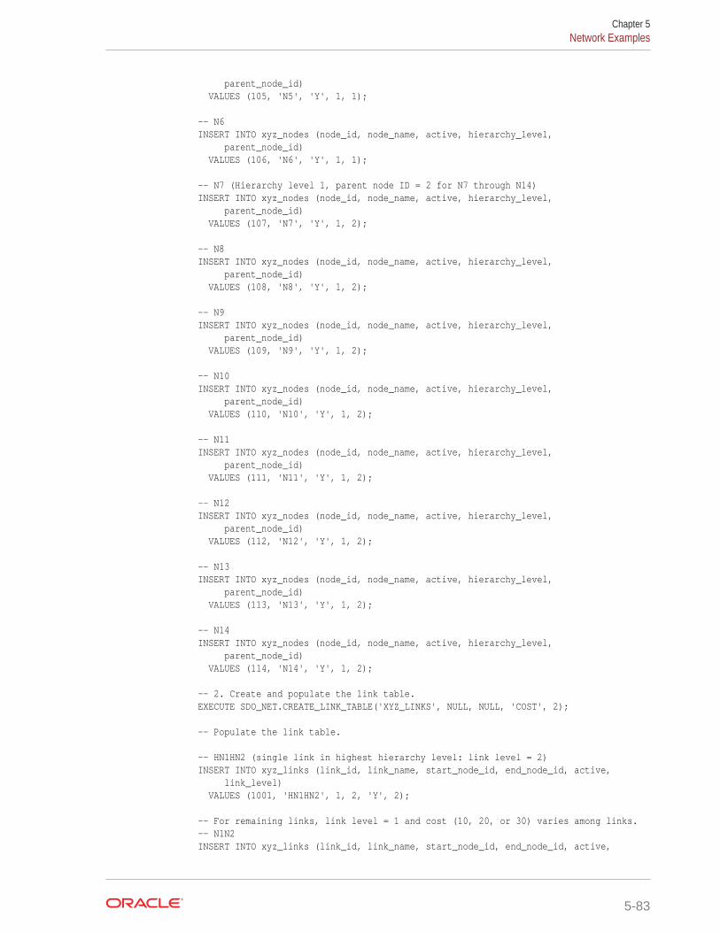
parent_node_id) VALUES (105, 'N5', 'Y', 1, 1); -- N6 INSERT INTO xyz_nodes (node_id, node_name, active, hierarchy_level, parent_node_id) VALUES (106, 'N6', 'Y', 1, 1); -- N7 (Hierarchy level 1, parent node ID = 2 for N7 through N14)INSERT INTO xyz_nodes (node_id, node_name, active, hierarchy_level, parent_node_id) VALUES (107, 'N7', 'Y', 1, 2); -- N8 INSERT INTO xyz_nodes (node_id, node_name, active, hierarchy_level, parent_node_id) VALUES (108, 'N8', 'Y', 1, 2); -- N9 INSERT INTO xyz_nodes (node_id, node_name, active, hierarchy_level, parent_node_id) VALUES (109, 'N9', 'Y', 1, 2); -- N10 INSERT INTO xyz_nodes (node_id, node_name, active, hierarchy_level, parent_node_id) VALUES (110, 'N10', 'Y', 1, 2); -- N11 INSERT INTO xyz_nodes (node_id, node_name, active, hierarchy_level, parent_node_id) VALUES (111, 'N11', 'Y', 1, 2); -- N12 INSERT INTO xyz_nodes (node_id, node_name, active, hierarchy_level, parent_node_id) VALUES (112, 'N12', 'Y', 1, 2); -- N13 INSERT INTO xyz_nodes (node_id, node_name, active, hierarchy_level, parent_node_id) VALUES (113, 'N13', 'Y', 1, 2); -- N14 INSERT INTO xyz_nodes (node_id, node_name, active, hierarchy_level, parent_node_id) VALUES (114, 'N14', 'Y', 1, 2); -- 2. Create and populate the link table.EXECUTE SDO_NET.CREATE_LINK_TABLE('XYZ_LINKS', NULL, NULL, 'COST', 2); -- Populate the link table. -- HN1HN2 (single link in highest hierarchy level: link level = 2)INSERT INTO xyz_links (link_id, link_name, start_node_id, end_node_id, active, link_level) VALUES (1001, 'HN1HN2', 1, 2, 'Y', 2); -- For remaining links, link level = 1 and cost (10, 20, or 30) varies among links.-- N1N2INSERT INTO xyz_links (link_id, link_name, start_node_id, end_node_id, active,
Chapter 5Network Examples
5-83
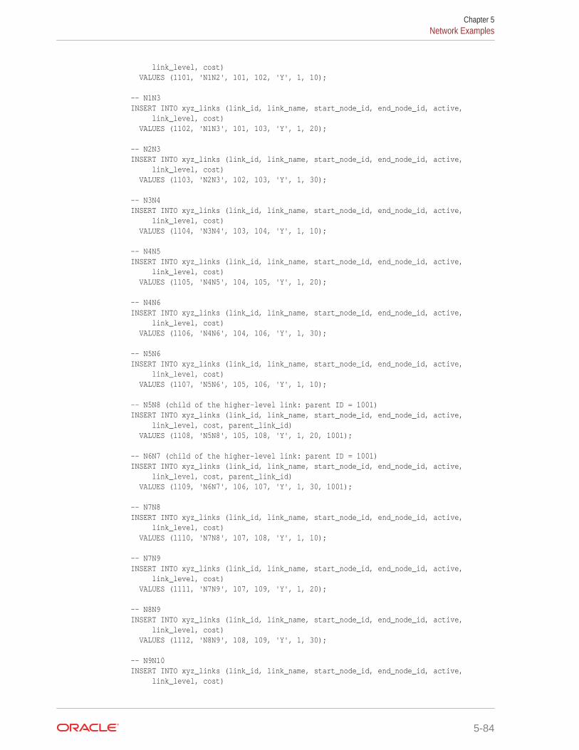
link_level, cost) VALUES (1101, 'N1N2', 101, 102, 'Y', 1, 10); -- N1N3INSERT INTO xyz_links (link_id, link_name, start_node_id, end_node_id, active, link_level, cost) VALUES (1102, 'N1N3', 101, 103, 'Y', 1, 20); -- N2N3INSERT INTO xyz_links (link_id, link_name, start_node_id, end_node_id, active, link_level, cost) VALUES (1103, 'N2N3', 102, 103, 'Y', 1, 30); -- N3N4INSERT INTO xyz_links (link_id, link_name, start_node_id, end_node_id, active, link_level, cost) VALUES (1104, 'N3N4', 103, 104, 'Y', 1, 10); -- N4N5INSERT INTO xyz_links (link_id, link_name, start_node_id, end_node_id, active, link_level, cost) VALUES (1105, 'N4N5', 104, 105, 'Y', 1, 20); -- N4N6INSERT INTO xyz_links (link_id, link_name, start_node_id, end_node_id, active, link_level, cost) VALUES (1106, 'N4N6', 104, 106, 'Y', 1, 30); -- N5N6INSERT INTO xyz_links (link_id, link_name, start_node_id, end_node_id, active, link_level, cost) VALUES (1107, 'N5N6', 105, 106, 'Y', 1, 10); -- N5N8 (child of the higher-level link: parent ID = 1001)INSERT INTO xyz_links (link_id, link_name, start_node_id, end_node_id, active, link_level, cost, parent_link_id) VALUES (1108, 'N5N8', 105, 108, 'Y', 1, 20, 1001); -- N6N7 (child of the higher-level link: parent ID = 1001)INSERT INTO xyz_links (link_id, link_name, start_node_id, end_node_id, active, link_level, cost, parent_link_id) VALUES (1109, 'N6N7', 106, 107, 'Y', 1, 30, 1001); -- N7N8INSERT INTO xyz_links (link_id, link_name, start_node_id, end_node_id, active, link_level, cost) VALUES (1110, 'N7N8', 107, 108, 'Y', 1, 10); -- N7N9INSERT INTO xyz_links (link_id, link_name, start_node_id, end_node_id, active, link_level, cost) VALUES (1111, 'N7N9', 107, 109, 'Y', 1, 20); -- N8N9INSERT INTO xyz_links (link_id, link_name, start_node_id, end_node_id, active, link_level, cost) VALUES (1112, 'N8N9', 108, 109, 'Y', 1, 30); -- N9N10INSERT INTO xyz_links (link_id, link_name, start_node_id, end_node_id, active, link_level, cost)
Chapter 5Network Examples
5-84
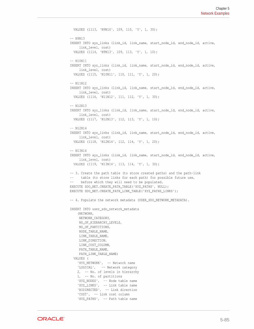
VALUES (1113, 'N9N10', 109, 110, 'Y', 1, 30); -- N9N13INSERT INTO xyz_links (link_id, link_name, start_node_id, end_node_id, active, link_level, cost) VALUES (1114, 'N9N13', 109, 113, 'Y', 1, 10); -- N10N11INSERT INTO xyz_links (link_id, link_name, start_node_id, end_node_id, active, link_level, cost) VALUES (1115, 'N10N11', 110, 111, 'Y', 1, 20); -- N11N12INSERT INTO xyz_links (link_id, link_name, start_node_id, end_node_id, active, link_level, cost) VALUES (1116, 'N11N12', 111, 112, 'Y', 1, 30); -- N12N13INSERT INTO xyz_links (link_id, link_name, start_node_id, end_node_id, active, link_level, cost) VALUES (1117, 'N12N13', 112, 113, 'Y', 1, 10); -- N12N14INSERT INTO xyz_links (link_id, link_name, start_node_id, end_node_id, active, link_level, cost) VALUES (1118, 'N12N14', 112, 114, 'Y', 1, 20); -- N13N14INSERT INTO xyz_links (link_id, link_name, start_node_id, end_node_id, active, link_level, cost) VALUES (1119, 'N13N14', 113, 114, 'Y', 1, 30); -- 3. Create the path table (to store created paths) and the path-link -- table (to store links for each path) for possible future use,-- before which they will need to be populated.EXECUTE SDO_NET.CREATE_PATH_TABLE('XYZ_PATHS', NULL);EXECUTE SDO_NET.CREATE_PATH_LINK_TABLE('XYZ_PATHS_LINKS'); -- 4. Populate the network metadata (USER_SDO_NETWORK_METADATA). INSERT INTO user_sdo_network_metadata (NETWORK, NETWORK_CATEGORY, NO_OF_HIERARCHY_LEVELS, NO_OF_PARTITIONS, NODE_TABLE_NAME, LINK_TABLE_NAME, LINK_DIRECTION, LINK_COST_COLUMN, PATH_TABLE_NAME, PATH_LINK_TABLE_NAME) VALUES ( 'XYZ_NETWORK', -- Network name 'LOGICAL', -- Network category 2, -- No. of levels in hierarchy 1, -- No. of partitions 'XYZ_NODES', -- Node table name 'XYZ_LINKS', -- Link table name 'BIDIRECTED', -- Link direction 'COST', -- Link cost column 'XYZ_PATHS', -- Path table name
Chapter 5Network Examples
5-85
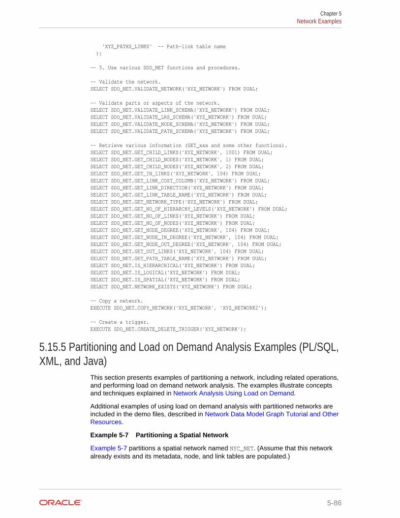
'XYZ_PATHS_LINKS' -- Path-link table name ); -- 5. Use various SDO_NET functions and procedures. -- Validate the network.SELECT SDO_NET.VALIDATE_NETWORK('XYZ_NETWORK') FROM DUAL; -- Validate parts or aspects of the network.SELECT SDO_NET.VALIDATE_LINK_SCHEMA('XYZ_NETWORK') FROM DUAL;SELECT SDO_NET.VALIDATE_LRS_SCHEMA('XYZ_NETWORK') FROM DUAL;SELECT SDO_NET.VALIDATE_NODE_SCHEMA('XYZ_NETWORK') FROM DUAL;SELECT SDO_NET.VALIDATE_PATH_SCHEMA('XYZ_NETWORK') FROM DUAL; -- Retrieve various information (GET_xxx and some other functions).SELECT SDO_NET.GET_CHILD_LINKS('XYZ_NETWORK', 1001) FROM DUAL;SELECT SDO_NET.GET_CHILD_NODES('XYZ_NETWORK', 1) FROM DUAL;SELECT SDO_NET.GET_CHILD_NODES('XYZ_NETWORK', 2) FROM DUAL;SELECT SDO_NET.GET_IN_LINKS('XYZ_NETWORK', 104) FROM DUAL;SELECT SDO_NET.GET_LINK_COST_COLUMN('XYZ_NETWORK') FROM DUAL;SELECT SDO_NET.GET_LINK_DIRECTION('XYZ_NETWORK') FROM DUAL;SELECT SDO_NET.GET_LINK_TABLE_NAME('XYZ_NETWORK') FROM DUAL;SELECT SDO_NET.GET_NETWORK_TYPE('XYZ_NETWORK') FROM DUAL;SELECT SDO_NET.GET_NO_OF_HIERARCHY_LEVELS('XYZ_NETWORK') FROM DUAL;SELECT SDO_NET.GET_NO_OF_LINKS('XYZ_NETWORK') FROM DUAL;SELECT SDO_NET.GET_NO_OF_NODES('XYZ_NETWORK') FROM DUAL;SELECT SDO_NET.GET_NODE_DEGREE('XYZ_NETWORK', 104) FROM DUAL;SELECT SDO_NET.GET_NODE_IN_DEGREE('XYZ_NETWORK', 104) FROM DUAL;SELECT SDO_NET.GET_NODE_OUT_DEGREE('XYZ_NETWORK', 104) FROM DUAL;SELECT SDO_NET.GET_OUT_LINKS('XYZ_NETWORK', 104) FROM DUAL;SELECT SDO_NET.GET_PATH_TABLE_NAME('XYZ_NETWORK') FROM DUAL;SELECT SDO_NET.IS_HIERARCHICAL('XYZ_NETWORK') FROM DUAL;SELECT SDO_NET.IS_LOGICAL('XYZ_NETWORK') FROM DUAL;SELECT SDO_NET.IS_SPATIAL('XYZ_NETWORK') FROM DUAL;SELECT SDO_NET.NETWORK_EXISTS('XYZ_NETWORK') FROM DUAL; -- Copy a network.EXECUTE SDO_NET.COPY_NETWORK('XYZ_NETWORK', 'XYZ_NETWORK2'); -- Create a trigger.EXECUTE SDO_NET.CREATE_DELETE_TRIGGER('XYZ_NETWORK');
5.15.5 Partitioning and Load on Demand Analysis Examples (PL/SQL,XML, and Java)
This section presents examples of partitioning a network, including related operations,and performing load on demand network analysis. The examples illustrate conceptsand techniques explained in Network Analysis Using Load on Demand.
Additional examples of using load on demand analysis with partitioned networks areincluded in the demo files, described in Network Data Model Graph Tutorial and OtherResources.
Example 5-7 Partitioning a Spatial Network
Example 5-7 partitions a spatial network named NYC_NET. (Assume that this networkalready exists and its metadata, node, and link tables are populated.)
Chapter 5Network Examples
5-86
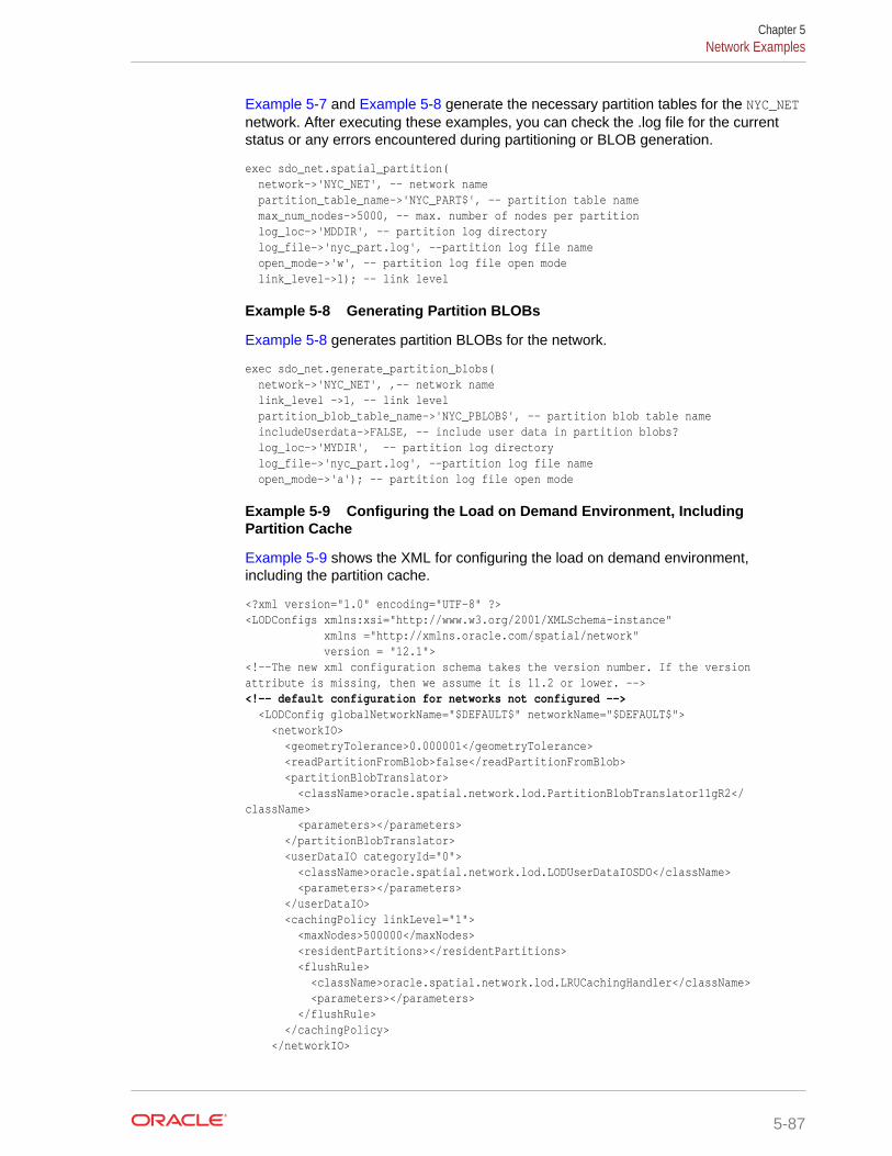
Example 5-7 and Example 5-8 generate the necessary partition tables for the NYC_NETnetwork. After executing these examples, you can check the .log file for the currentstatus or any errors encountered during partitioning or BLOB generation.
exec sdo_net.spatial_partition( network->'NYC_NET', -- network name partition_table_name->'NYC_PART$', -- partition table name max_num_nodes->5000, -- max. number of nodes per partition log_loc->'MDDIR', -- partition log directory log_file->'nyc_part.log', --partition log file name open_mode->'w', -- partition log file open mode link_level->1); -- link level
Example 5-8 Generating Partition BLOBs
Example 5-8 generates partition BLOBs for the network.
exec sdo_net.generate_partition_blobs( network->'NYC_NET', ,-- network name link_level ->1, -- link level partition_blob_table_name->'NYC_PBLOB$', -- partition blob table name includeUserdata->FALSE, -- include user data in partition blobs? log_loc->'MYDIR', -- partition log directory log_file->'nyc_part.log', --partition log file name open_mode->'a'); -- partition log file open mode
Example 5-9 Configuring the Load on Demand Environment, IncludingPartition Cache
Example 5-9 shows the XML for configuring the load on demand environment,including the partition cache.
<?xml version="1.0" encoding="UTF-8" ?><LODConfigs xmlns:xsi="http://www.w3.org/2001/XMLSchema-instance" xmlns ="http://xmlns.oracle.com/spatial/network" version = "12.1"> <!--The new xml configuration schema takes the version number. If the version attribute is missing, then we assume it is 11.2 or lower. --><!-- default configuration for networks not configured --> <LODConfig globalNetworkName="$DEFAULT$" networkName="$DEFAULT$"> <networkIO> <geometryTolerance>0.000001</geometryTolerance> <readPartitionFromBlob>false</readPartitionFromBlob> <partitionBlobTranslator> <className>oracle.spatial.network.lod.PartitionBlobTranslator11gR2</className> <parameters></parameters> </partitionBlobTranslator> <userDataIO categoryId="0"> <className>oracle.spatial.network.lod.LODUserDataIOSDO</className> <parameters></parameters> </userDataIO> <cachingPolicy linkLevel="1"> <maxNodes>500000</maxNodes> <residentPartitions></residentPartitions> <flushRule> <className>oracle.spatial.network.lod.LRUCachingHandler</className> <parameters></parameters> </flushRule> </cachingPolicy> </networkIO>
Chapter 5Network Examples
5-87

<networkAnalysis> <linkLevelSelector> <className>oracle.spatial.network.lod.DummyLinkLevelSelector</className> <parameters></parameters> </linkLevelSelector> <withinCostPolygonTolerance>0.05</withinCostPolygonTolerance> </networkAnalysis> </LODConfig> <LODConfig globalNetworkName="SAMPLE_NETWORK" networkName="SAMPLE_NETWORK"> <networkIO> <geometryTolerance>0.000001</geometryTolerance> <readPartitionFromBlob>true</readPartitionFromBlob> <partitionBlobTranslator> <className>oracle.spatial.router.ndm.RouterPartitionBlobTranslator11gR2</className> <parameters></parameters> </partitionBlobTranslator> <userDataIO categoryId="0"> <className>oracle.spatial.network.lod.LODUserDataIOSDO</className> <parameters></parameters> </userDataIO> <userDataIO categoryId="1"> <className>oracle.spatial.router.ndm.RouterUserDataIO</className> <parameters></parameters> </userDataIO> <cachingPolicy linkLevel="1"> <maxNodes>200000</maxNodes> <residentPartitions></residentPartitions> <flushRule> <className>oracle.spatial.network.lod.LRUCachingHandler</className> <parameters></parameters> </flushRule> </cachingPolicy> <cachingPolicy linkLevel="2"> <maxNodes>800000</maxNodes> <residentPartitions>0</residentPartitions> <flushRule> <className>oracle.spatial.network.lod.LRUCachingHandler</className> <parameters></parameters> </flushRule> </cachingPolicy> </networkIO> <networkAnalysis> </networkAnalysis> </LODConfig></LODConfigs>
Example 5-10 Reloading the Load on Demand Configuration (Java API)
Example 5-10 and Example 5-11 show the Java and PL/SQL APIs, respectively, forreloading the load on demand configuration.
InputStream config = ClassLoader.getSystemResourceAsStream( "netlodcfg.xml");LODNetworkManager.getConfigManager().loadConfig(config);
Example 5-11 Reloading the Load on Demand Configuration (PL/SQL API)
EXECUTE SDO_NET.LOAD_CONFIG('WORK_DIR', 'netlodcfg.xml');
Chapter 5Network Examples
5-88
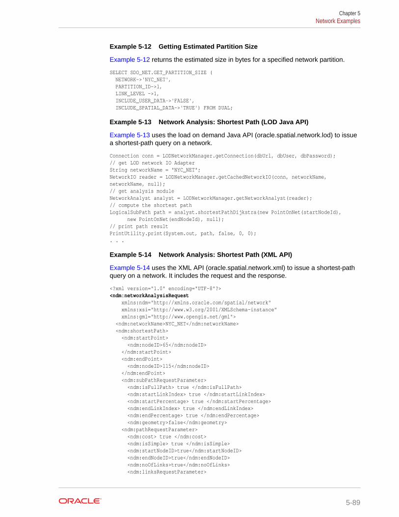
Example 5-12 Getting Estimated Partition Size
Example 5-12 returns the estimated size in bytes for a specified network partition.
SELECT SDO_NET.GET_PARTITION_SIZE ( NETWORK->'NYC_NET', PARTITION_ID->1, LINK_LEVEL ->1, INCLUDE_USER_DATA->'FALSE', INCLUDE_SPATIAL_DATA->'TRUE') FROM DUAL;
Example 5-13 Network Analysis: Shortest Path (LOD Java API)
Example 5-13 uses the load on demand Java API (oracle.spatial.network.lod) to issuea shortest-path query on a network.
Connection conn = LODNetworkManager.getConnection(dbUrl, dbUser, dbPassword);// get LOD network IO AdapterString networkName = "NYC_NET";NetworkIO reader = LODNetworkManager.getCachedNetworkIO(conn, networkName, networkName, null);// get analysis moduleNetworkAnalyst analyst = LODNetworkManager.getNetworkAnalyst(reader);// compute the shortest pathLogicalSubPath path = analyst.shortestPathDijkstra(new PointOnNet(startNodeId), new PointOnNet(endNodeId), null);// print path resultPrintUtility.print(System.out, path, false, 0, 0);. . .
Example 5-14 Network Analysis: Shortest Path (XML API)
Example 5-14 uses the XML API (oracle.spatial.network.xml) to issue a shortest-pathquery on a network. It includes the request and the response.
<?xml version="1.0" encoding="UTF-8"?><ndm:networkAnalysisRequest xmlns:ndm="http://xmlns.oracle.com/spatial/network" xmlns:xsi="http://www.w3.org/2001/XMLSchema-instance" xmlns:gml="http://www.opengis.net/gml"> <ndm:networkName>NYC_NET</ndm:networkName> <ndm:shortestPath> <ndm:startPoint> <ndm:nodeID>65</ndm:nodeID> </ndm:startPoint> <ndm:endPoint> <ndm:nodeID>115</ndm:nodeID> </ndm:endPoint> <ndm:subPathRequestParameter> <ndm:isFullPath> true </ndm:isFullPath> <ndm:startLinkIndex> true </ndm:startLinkIndex> <ndm:startPercentage> true </ndm:startPercentage> <ndm:endLinkIndex> true </ndm:endLinkIndex> <ndm:endPercentage> true </ndm:endPercentage> <ndm:geometry>false</ndm:geometry> <ndm:pathRequestParameter> <ndm:cost> true </ndm:cost> <ndm:isSimple> true </ndm:isSimple> <ndm:startNodeID>true</ndm:startNodeID> <ndm:endNodeID>true</ndm:endNodeID> <ndm:noOfLinks>true</ndm:noOfLinks> <ndm:linksRequestParameter>
Chapter 5Network Examples
5-89
<ndm:onlyLinkID>true</ndm:onlyLinkID> </ndm:linksRequestParameter> <ndm:nodesRequestParameter> <ndm:onlyNodeID>true</ndm:onlyNodeID> </ndm:nodesRequestParameter> <ndm:geometry>true</ndm:geometry> </ndm:pathRequestParameter> </ndm:subPathRequestParameter> </ndm:shortestPath></ndm:networkAnalysisRequest> <?xml version = '1.0' encoding = 'UTF-8'?><ndm:networkAnalysisResponse xmlns:xsi="http://www.w3.org/2001/XMLSchema-instance" xmlns:ndm="http://xmlns.oracle.com/spatial/network" xmlns:gml="http://www.opengis.net/gml"> <ndm:networkName>NYC_NET</ndm:networkName> <ndm:shortestPath> <ndm:subPathResponse> <ndm:isFullPath>true</ndm:isFullPath> <ndm:startLinkIndex>0</ndm:startLinkIndex> <ndm:startPercentage>0.0</ndm:startPercentage> <ndm:endLinkIndex>17</ndm:endLinkIndex> <ndm:endPercentage>1.0</ndm:endPercentage> <ndm:pathResponse> <ndm:cost>6173.212694405703</ndm:cost> <ndm:isSimple>true</ndm:isSimple> <ndm:startNodeID>65</ndm:startNodeID> <ndm:endNodeID>115</ndm:endNodeID> <ndm:noOfLinks>18</ndm:noOfLinks> <ndm:linkIDs>145477046 145477044 145477042 145477039 145476926 145476930 145480892 145480891 145476873 145476871 145477023 145489019 145489020 145476851 145488986 145488987 145476913 145476905 </ndm:linkIDs> <ndm:nodeIDs>65 64 60 57 58 61 71 70 73 87 97 95 91 101 102 104 117 120 115 </ndm:nodeIDs> <ndm:geometry> <gml:LineString> <gml:coordinates>-71.707462,43.555262 -71.707521,43.555601… </gml:coordinates> </gml:LineString> </ndm:geometry> </ndm:pathResponse> </ndm:subPathResponse> </ndm:shortestPath></ndm:networkAnalysisResponse>
5.15.6 User-Defined Data Examples (PL/SQL and Java)This section presents examples of using network user-defined data, which is theinformation (not related to connectivity) that users want to associate with a networkrepresentation. The USER_SDO_NETWORK_USER_DATA andALL_SDO_NETWORK_USER_DATA metadata views (described in xxx_SDO_NETWORK_USER_DATA Views) contain information about user-defineddata.
To use user-defined data, you must set the USER_DEFINED_DATA column value to Yin the appropriate xxx_SDO_NETWORK_METADATA views (described in xxx_SDO_NETWORK_METADATA Views).
Chapter 5Network Examples
5-90
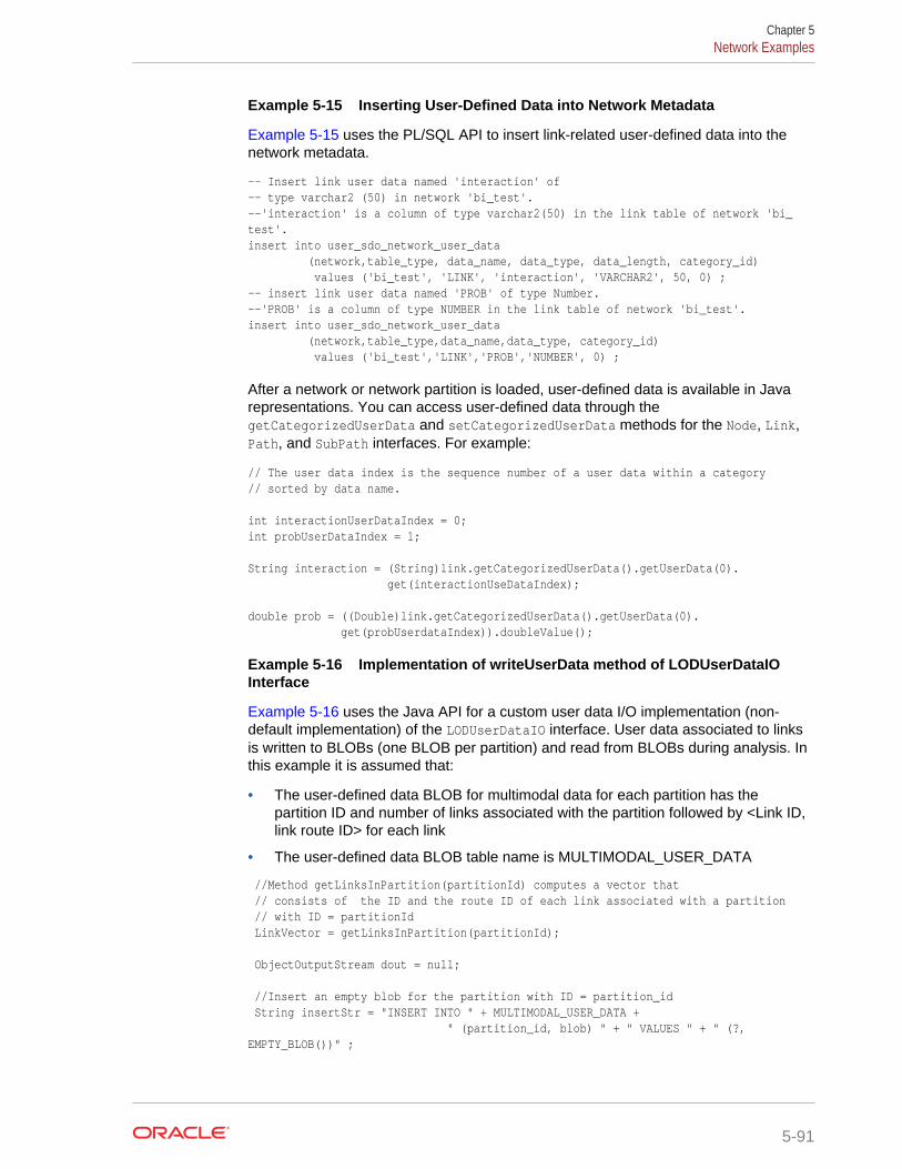
Example 5-15 Inserting User-Defined Data into Network Metadata
Example 5-15 uses the PL/SQL API to insert link-related user-defined data into thenetwork metadata.
-- Insert link user data named 'interaction' of-- type varchar2 (50) in network 'bi_test'.--'interaction' is a column of type varchar2(50) in the link table of network 'bi_test'.insert into user_sdo_network_user_data (network,table_type, data_name, data_type, data_length, category_id) values ('bi_test', 'LINK', 'interaction', 'VARCHAR2', 50, 0) ;-- insert link user data named 'PROB' of type Number.--'PROB' is a column of type NUMBER in the link table of network 'bi_test'.insert into user_sdo_network_user_data (network,table_type,data_name,data_type, category_id) values ('bi_test','LINK','PROB','NUMBER', 0) ;
After a network or network partition is loaded, user-defined data is available in Javarepresentations. You can access user-defined data through thegetCategorizedUserData and setCategorizedUserData methods for the Node, Link,Path, and SubPath interfaces. For example:
// The user data index is the sequence number of a user data within a category// sorted by data name. int interactionUserDataIndex = 0;int probUserDataIndex = 1; String interaction = (String)link.getCategorizedUserData().getUserData(0). get(interactionUseDataIndex); double prob = ((Double)link.getCategorizedUserData().getUserData(0). get(probUserdataIndex)).doubleValue();
Example 5-16 Implementation of writeUserData method of LODUserDataIOInterface
Example 5-16 uses the Java API for a custom user data I/O implementation (non-default implementation) of the LODUserDataIO interface. User data associated to linksis written to BLOBs (one BLOB per partition) and read from BLOBs during analysis. Inthis example it is assumed that:
• The user-defined data BLOB for multimodal data for each partition has thepartition ID and number of links associated with the partition followed by <Link ID,link route ID> for each link
• The user-defined data BLOB table name is MULTIMODAL_USER_DATA
//Method getLinksInPartition(partitionId) computes a vector that // consists of the ID and the route ID of each link associated with a partition // with ID = partitionId LinkVector = getLinksInPartition(partitionId); ObjectOutputStream dout = null; //Insert an empty blob for the partition with ID = partition_id String insertStr = "INSERT INTO " + MULTIMODAL_USER_DATA + " (partition_id, blob) " + " VALUES " + " (?, EMPTY_BLOB())" ;
Chapter 5Network Examples
5-91

PreparedStatement stmt = conn.prepareStatement(insertStr); stmt.setInt(1,partitionId); int n = stmt.executeUpdate(); stmt.close(); //lock the row for blob update String lockRowStr = "SELECT blob FROM " + MULTIMODAL_USER_DATA + " WHERE partition_id = ? " + " FOR UPDATE"; stmt = conn.prepareStatement(lockRowStr); stmt.setInt(1,partitionId); ResultSet rs = stmt.executeQuery(); rs.next(); oracle.sql.BLOB userDataBlob = (oracle.sql.BLOB) rs.getBlob(1); stmt.close(); OutputStream blobOut = ((oracle.sql.BLOB) userDataBlob).setBinaryStream(1); dout = new ObjectOutputStream(blobOut); //write partition ID dout.writeInt(partitionId); int numLinks = linkVector.size() for (int i=0; i<linkVector.size(); i++) { //MultimodalLink is a class with variables link ID and route ID MultimodalLink link = (MultimodalLink) linkVector.elementAt(i); //write link ID dout.writeLong(link.getLinkId()); // write route ID into file dout.writeInt(link.getRouteId()); } dout.close(); blobOut.close(); rs.close();
Example 5-17 Implementation of readUserData method of LODUserDataIOInterface
In Example 5-17, the user-defined data is accessed through thegetCategorizedUserData and setCategorizedUserData methods for the Node, Link,Path, and SubPath interfaces and the getUserData and setUserData methods of theCategorizedUserData interface.
//Read the blob for the required partition from the user data blob table// In this example,// MULTIMODAL_USER_DATA is the name of user –defined data blob tableBLOB multimodalBlob = null;String queryStr = "SELECT blob FROM " + MULTIMODAL_USER_DATA " WHERE partition_id = ?";PreparedStatement stmt = conn.prepareStatement(queryStr);stmt.setInt(1,partitionId);ResultSet rs = stmt.executeQuery();if (rs.next()) { multimodalBlob = (oracle.sql.BLOB)rs.getBlob(1);} // Materialize the blob value as an input stream InputStream is = multimodalBlob.getBinaryStream();
Chapter 5Network Examples
5-92
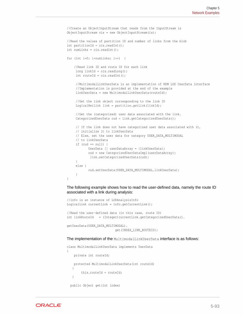
//Create an ObjectInputStream that reads from the InputStream isObjectInputStream ois = new ObjectInputStream(is); //Read the values of partition ID and number of links from the blobint partitionId = ois.readInt();int numLinks = ois.readInt(); for (int i=0; i<numLinks; i++) { //Read link ID and route ID for each link long linkId = ois.readLong(); int routeId = ois.readInt(); //MultimodalLinkUserData is an implementation of NDM LOD UserData interface //Implementation is provided at the end of the example linkUserData = new MultimodalLinkUserData(routeId); //Get the link object corresponding to the link ID LogicalNetLink link = partition.getLink(linkId); //Get the (categorized) user data associated with the link. CategorizedUserData cud = link.getCategorizedUserData(); // If the link does not have categorized user data associated with it, // initialize it to linkUserData // Else, set the user data for category USER_DATA_MULTIMODAL // to linkUserData if (cud == null) { UserData [] userDataArray = {linkUserData}; cud = new CategorizedUserDataImpl(userDataArray); link.setCategorizedUserData(cud); } else { cud.setUserData(USER_DATA_MULTIMODAL,linkUserData); }}
The following example shows how to read the user-defined data, namely the route IDassociated with a link during analysis:
//info is an instance of LODAnalysisInfo LogicalLink currentLink = info.getCurrentLink(); //Read the user-defined data (in this case, route ID) int linkRouteId = (Integer)currentLink.getCategorizedUserData(). getUserData(USER_DATA_MULTIMODAL). get(INDEX_LINK_ROUTEID);
The implementation of the MultimodalLinkUserData interface is as follows:
class MultimodalLinkUserData implements UserData{ private int routeId; protected MultimodalLinkUserData(int routeId) { this.routeId = routeId; } public Object get(int index)
Chapter 5Network Examples
5-93
{ switch(index) { case INDEX_LINK_ROUTEID: return routeId; } return null; } public void set(int index, Object userData) { switch(index) { case INDEX_LINK_ROUTEID: this.routeId = (Integer) userData; } } public int getNumberOfUserData() { return 1; } public Object clone(){ return new MultimodalLinkUserData(routeId); }}
5.16 Network Data Model Graph Tutorial and OtherResources
Network Data Model Graph learning resources are available.
http://www.oracle.com/technetwork/database-options/spatialandgraph on theOracle Technology Network provides links to valuable resources to help you getstarted with Oracle Spatial and Graph technologies, including the Network Data Model(NDM) Graph. The Network Data Model Graph resources include the following:
• A Network Data Model Graph tutorial (ndm_tutorial.zip on http://www.oracle.com/technetwork/indexes/samplecode/spatial-1433316.html)outlines the steps to set up and configure a network, and to conduct the analysis.It also includes sample code and a web application that demonstrates how to useOracle Maps to display analysis results.
• An NDM white paper ("A Load-On-Demand Approach to Handling LargeNetworks in the Oracle Spatial and Graph Network Data Model Graph") providesdetailed explanations and examples.
• The NDM editor, provided as a demo intended for small and medium-sizenetworks, is a graphical tool to view, browse, and navigate through data that isstored in the network data model. You can also use this tool to perform analysis onnetworks (shortest path, nearest neighbor, minimum cost spanning tree, and soon), and to add and delete nodes, links, and paths.
• NFE (Network Feature Editing) Java API documentation provides examples ofNFE capabilities. It also provides electricity and water network examples, and aNFE data dictionary with NFE table descriptions.
Chapter 5Network Data Model Graph Tutorial and Other Resources
5-94

You are encouraged to examine the Java examples before starting developmentwith NFE.
• The NFE editor is a sample application to create NFE models and manage them.The models can be created in the From Scratch mode or the Over ExistingNetwork Model mode. You can create and manage feature layers, feature classesand features. Additionally, a video presentation shows how to create and manageNFE models with the NFE editor.
5.17 README File for Spatial and Graph and RelatedFeatures
A README.txt file supplements the information in the following manuals: Oracle Spatialand Graph Developer's Guide, Oracle Spatial and Graph GeoRaster Developer'sGuide, and Oracle Spatial and Graph Topology Data Model and Network Data ModelGraph Developer's Guide (this manual).This file is located at:
$ORACLE_HOME/md/doc/README.txt
Chapter 5README File for Spatial and Graph and Related Features
5-95
6SDO_NET Package Subprograms
The MDSYS.SDO_NET package contains subprograms (functions and procedures) formanaging networks.
To use the subprograms in this chapter, you must understand the conceptualinformation in Network Data Model Graph Overview.
For a listing of the subprograms grouped in logical categories, see Network DataModel Graph PL/SQL Interface. The rest of this chapter provides reference informationabout the subprograms, listed in alphabetical order.
• SDO_NET.ADD_CHILD_FEATURE
• SDO_NET.ADD_CHILD_FEATURES
• SDO_NET.ADD_FEATURE
• SDO_NET.ADD_FEATURE_ELEMENT
• SDO_NET.ADD_FEATURE_ELEMENTS
• SDO_NET.ADD_FEATURE_LAYER
• SDO_NET.COMPUTE_PATH_GEOMETRY
• SDO_NET.COPY_NETWORK
• SDO_NET.CREATE_LINK_TABLE
• SDO_NET.CREATE_LOGICAL_NETWORK
• SDO_NET.CREATE_LRS_NETWORK
• SDO_NET.CREATE_LRS_TABLE
• SDO_NET.CREATE_NODE_TABLE
• SDO_NET.CREATE_PARTITION_TABLE
• SDO_NET.CREATE_PATH_LINK_TABLE
• SDO_NET.CREATE_PATH_TABLE
• SDO_NET.CREATE_SDO_NETWORK
• SDO_NET.CREATE_SUBPATH_TABLE
• SDO_NET.CREATE_TOPO_NETWORK
• SDO_NET.DELETE_CHILD_FEATURES
• SDO_NET.DELETE_CHILD_FEATURES_AT
• SDO_NET.DELETE_DANGLING_FEATURES
• SDO_NET.DELETE_DANGLING_LINKS
• SDO_NET.DELETE_DANGLING_NODES
• SDO_NET.DELETE_FEATURE_ELEMENTS
• SDO_NET.DELETE_FEATURE_ELEMENTS_AT
6-1
• SDO_NET.DELETE_FEATURES
• SDO_NET.DELETE_LINK
• SDO_NET.DELETE_NODE
• SDO_NET.DELETE_PATH
• SDO_NET.DELETE_PHANTOM_FEATURES
• SDO_NET.DELETE_SUBPATH
• SDO_NET.DEREGISTER_CONSTRAINT
• SDO_NET.DROP_FEATURE_LAYER
• SDO_NET.DROP_NETWORK
• SDO_NET.FIND_CONNECTED_COMPONENTS
• SDO_NET.GENERATE_NODE_LEVELS
• SDO_NET.GENERATE_PARTITION_BLOB
• SDO_NET.GENERATE_PARTITION_BLOBS
• SDO_NET.GET_CHILD_FEATURE_IDS
• SDO_NET.GET_CHILD_LINKS
• SDO_NET.GET_CHILD_NODES
• SDO_NET.GET_DANGLING_FEATURES
• SDO_NET.GET_DANGLING_LINKS
• SDO_NET.GET_DANGLING_NODES
• SDO_NET.GET_FEATURE_ELEMENTS
• SDO_NET.GET_FEATURE_LAYER_ID
• SDO_NET.GET_FEATURES_ON_LINKS
• SDO_NET.GET_FEATURES_ON_NODES
• SDO_NET.GET_GEOMETRY_TYPE
• SDO_NET.GET_IN_LINKS
• SDO_NET.GET_INVALID_LINKS
• SDO_NET.GET_INVALID_NODES
• SDO_NET.GET_INVALID_PATHS
• SDO_NET.GET_ISOLATED_NODES
• SDO_NET.GET_LINK_COST_COLUMN
• SDO_NET.GET_LINK_DIRECTION
• SDO_NET.GET_LINK_GEOM_COLUMN
• SDO_NET.GET_LINK_GEOMETRY
• SDO_NET.GET_LINK_TABLE_NAME
• SDO_NET.GET_LINKS_IN_PATH
• SDO_NET.GET_LRS_GEOM_COLUMN
• SDO_NET.GET_LRS_LINK_GEOMETRY
Chapter 6
6-2
• SDO_NET.GET_LRS_NODE_GEOMETRY
• SDO_NET.GET_LRS_TABLE_NAME
• SDO_NET.GET_NETWORK_TYPE
• SDO_NET.GET_NO_OF_HIERARCHY_LEVELS
• SDO_NET.GET_NO_OF_LINKS
• SDO_NET.GET_NO_OF_NODES
• SDO_NET.GET_NODE_DEGREE
• SDO_NET.GET_NODE_GEOM_COLUMN
• SDO_NET.GET_NODE_GEOMETRY
• SDO_NET.GET_NODE_IN_DEGREE
• SDO_NET.GET_NODE_OUT_DEGREE
• SDO_NET.GET_NODE_TABLE_NAME
• SDO_NET.GET_OUT_LINKS
• SDO_NET.GET_PARENT_FEATURE_IDS
• SDO_NET.GET_PARTITION_SIZE
• SDO_NET.GET_PATH_GEOM_COLUMN
• SDO_NET.GET_PATH_TABLE_NAME
• SDO_NET.GET_PERCENTAGE
• SDO_NET.GET_PHANTOM_FEATURES
• SDO_NET.GET_PT
• SDO_NET.IS_HIERARCHICAL
• SDO_NET.IS_LINK_IN_PATH
• SDO_NET.IS_LOGICAL
• SDO_NET.IS_NODE_IN_PATH
• SDO_NET.IS_SPATIAL
• SDO_NET.LOAD_CONFIG
• SDO_NET.LOGICAL_PARTITION
• SDO_NET.LOGICAL_POWERLAW_PARTITION
• SDO_NET.LRS_GEOMETRY_NETWORK
• SDO_NET.NETWORK_EXISTS
• SDO_NET.POST_XML
• SDO_NET.REGISTER_CONSTRAINT
• SDO_NET.SDO_GEOMETRY_NETWORK
• SDO_NET.SET_LOGGING_LEVEL
• SDO_NET.SET_MAX_JAVA_HEAP_SIZE
• SDO_NET.SPATIAL_PARTITION
• SDO_NET.TOPO_GEOMETRY_NETWORK
Chapter 6
6-3

• SDO_NET.UPDATE_FEATURE
• SDO_NET.UPDATE_FEATURE_ELEMENT
• SDO_NET.VALIDATE_LINK_SCHEMA
• SDO_NET.VALIDATE_LRS_SCHEMA
• SDO_NET.VALIDATE_NETWORK
• SDO_NET.VALIDATE_NODE_SCHEMA
• SDO_NET.VALIDATE_PARTITION_SCHEMA
• SDO_NET.VALIDATE_PATH_SCHEMA
• SDO_NET.VALIDATE_SUBPATH_SCHEMA
6.1 SDO_NET.ADD_CHILD_FEATUREFormat
SDO_NET.ADD_CHILD_FEATURE( parent_layer_id IN NUMBER, parent_feature_id IN NUMBER, child_layer_id IN NUMBER, child_feature_id IN SDO_NET_LAYER_FEAT, sequence_number IN NUMBER DEFAULT NULL, check_integrity IN BOOLEAN DEFAULT TRUE);
Description
Associates a feature as a child feature of a specified parent feature.
Parameters
parent_layer_idID of the parent feature layer.
parent_feature_idID of the feature that is to become the parent feature of the specified child feature.
child_layer_idID of the child feature layer.
child_feature_idID of the feature to be associated as a child feature of the specified parent feature.(The SDO_NET_LAYER_FEAT type is described in Data Types Used for FeatureModeling.)
sequence_numberSequence number of the child_feature_id feature in the child feature layer. If thisparameter is null, a sequence number after the last current number is assigned.
check_integrityTRUE (the default) checks if the child feature exists; and if it does not exist, an error isgenerated. FALSE does not check if the child feature exists.
Usage Notes
The specified child feature must already exist.
Chapter 6SDO_NET.ADD_CHILD_FEATURE
6-4
To associate multiple features as child features, use the SDO_NET.ADD_CHILD_FEATURES procedure.
Examples
The following example adds a child feature at sequence number 2.
DECLARE parent_layer_id NUMBER; parent_feature_id NUMBER := 1; child_layer_id NUMBER; child_feature_id NUMBER := 3;BEGIN parent_layer_id := sdo_net.get_feature_layer_id('GRID', 'PARENT_LAYER'); child_layer_id := sdo_net.get_feature_layer_id('GRID', 'POI'); sdo_net.add_child_feature(parent_layer_id, parent_feature_id, child_layer_id, child_feature_id, 2, true);END;/
6.2 SDO_NET.ADD_CHILD_FEATURESFormat
SDO_NET.ADD_CHILD_FEATURES( parent_layer_id IN NUMBER, parent_feature_id IN NUMBER, child_feature_ids IN SDO_NET_LAYER_FEAT_ARRAY, check_integrity IN BOOLEAN DEFAULT TRUE);
Description
Associates multiple features as child features of a specified parent feature.
Parameters
parent_layer_idID of the parent feature layer.
parent_feature_idID of the feature that is to become the parent feature of the specified child features.
child_feature_idsIDs of features to be associated as child features of the specified parent feature. (TheSDO_NET_LAYER_FEAT_ARRAY type is described in Data Types Used for FeatureModeling.)
check_integrityTRUE (the default) checks if the child features exist; and if any do not exist, an error isgenerated. FALSE does not check if the child features exist.
Usage Notes
The specified child features must already exist.
To associate a single feature as a child feature, use the SDO_NET.ADD_CHILD_FEATURE procedure.
Chapter 6SDO_NET.ADD_CHILD_FEATURES
6-5
Examples
The following example adds two child features at the end of the parent feature.
DECLARE parent_layer_id NUMBER; parent_feature_id NUMBER := 1; child_layer_id NUMBER; child_feature_ids SDO_NET_LAYER_FEAT_ARRAY := SDO_NET_LAYER_FEAT_ARRAY();BEGIN parent_layer_id := sdo_net.get_feature_layer_id('GRID', 'PARENT_LAYER'); child_layer_id := sdo_net.get_feature_layer_id('GRID', 'POI'); child_feature_ids.extend; child_feature_ids(1) := SDO_NET_LAYER_FEAT(child_layer_id, 4); child_feature_ids.extend; child_feature_ids(2) := SDO_NET_LAYER_FEAT(child_layer_id, 10); sdo_net.add_child_features(parent_layer_id, parent_feature_id, child_feature_ids, true);END;/
6.3 SDO_NET.ADD_FEATUREFormat
SDO_NET.ADD_FEATURE( feature_layer_id IN NUMBER, feature_id IN NUMBER, feature_elements IN SDO_NET_FEAT_ELEM_ARRAY DEFAULT NULL, child_feature_ids IN SDO_NET_LAYER_FEAT_ARRAY DEFAULT NULL, check_integrity IN BOOLEAN DEFAULT TRUE);
Description
Adds a feature to a feature layer.
Parameters
feature_layer_idID of the feature layer to which to add the feature.
feature_idID of the feature to be added to the feature layer.
feature_elementsFeature elements of the feature to be added. If this parameter is null, no featureelements are defined for this feature. (The SDO_NET_FEAT_ELEM_ARRAY type isdescribed in Data Types Used for Feature Modeling.)
child_feature_idsIDs of the child features of the feature that are to be added along with the feature. Ifthis parameter is null, no child features are to be added. (TheSDO_NET_LAYER_FEAT_ARRAY type is described in Data Types Used for FeatureModeling.)
Chapter 6SDO_NET.ADD_FEATURE
6-6
check_integrityTRUE (the default) checks if the input network elements exist; and if any do not exist,an error is generated. FALSE does not check if the input network elements exist.
Usage Notes
To update a feature in a feature layer, use the SDO_NET.UPDATE_FEATUREprocedure.
Examples
The following example adds a feature associated with a point at 20% on link 1314.
DECLARE feature_layer_id NUMBER; feature_id NUMBER := 1; elements SDO_NET_FEAT_ELEM_ARRAY := SDO_NET_FEAT_ELEM_ARRAY(); link_id NUMBER := 1314;BEGIN feature_layer_id := sdo_net.get_feature_layer_id('GRID', 'POI'); elements.extend; elements(1) := SDO_NET_FEAT_ELEM(SDO_NET.FEAT_ELEM_TYPE_POL, link_id, 0.2, null); sdo_net.add_feature(feature_layer_id, feature_id, elements, null); END;/
6.4 SDO_NET.ADD_FEATURE_ELEMENTFormat
SDO_NET.ADD_FEATURE_ELEMENT( feature_layer_id IN NUMBER, feature_id IN NUMBER, feature_element IN SDO_NET_FEAT_ELEM, sequence_number IN NUMBER DEFAULT NULL, check_integrity IN BOOLEAN DEFAULT TRUE);
Description
Adds a feature element to a feature.
Parameters
feature_layer_idID of the feature layer for the feature.
feature_idID of the feature.
feature_elementFeature element to be added to the feature. This feature element is automaticallyappended to the end of any existing feature elements in the feature. (TheSDO_NET_FEAT_ELEM type is described in Data Types Used for Feature Modeling.)
sequence_numberSequence number of the added feature element in the feature. If this parameter isnull, a sequence number after the last current number is assigned.
Chapter 6SDO_NET.ADD_FEATURE_ELEMENT
6-7
check_integrityTRUE (the default) checks if the input network elements exist; and if any do not exist,an error is generated. FALSE does not check if the input network elements exist.
Usage Notes
To add multiple feature elements to a feature in a single operation, use the SDO_NET.ADD_FEATURE_ELEMENTS procedure.
To update a feature element, use the SDO_NET.UPDATE_FEATURE_ELEMENTprocedure.
Examples
The following example adds a point feature for node ID 13 at sequence number 2.
DECLARE feature_layer_id NUMBER; feature_id NUMBER := 1; feature_element SDO_NET_FEAT_ELEM; node_id NUMBER := 13;BEGIN feature_layer_id := sdo_net.get_feature_layer_id('GRID', 'POI'); feature_element := SDO_NET_FEAT_ELEM(SDO_NET.FEAT_ELEM_TYPE_PON, node_id, null, null); sdo_net.add_feature_element(feature_layer_id, feature_id, feature_element, 2);END;/
6.5 SDO_NET.ADD_FEATURE_ELEMENTSFormat
SDO_NET.ADD_FEATURE_ELEMENTS( feature_layer_id IN NUMBER, feature_id IN NUMBER, feature_elements IN SDO_NET_FEAT_ELEM,_ARRAY, check_integrity IN BOOLEAN DEFAULT TRUE);
Description
Adds an array of feature elements to a feature.
Parameters
feature_layer_idID of the feature layer for the feature.
feature_idID of the feature.
feature_elementsFeature elements to be added to the feature. These feature elements areautomatically appended to the end of any existing feature elements in the feature.(The SDO_NET_FEAT_ELEM_ARRAY type is described in Data Types Used forFeature Modeling.)
Chapter 6SDO_NET.ADD_FEATURE_ELEMENTS
6-8
check_integrityTRUE (the default) checks if the input network elements exist; and if any do not exist,an error is generated. FALSE does not check if the input network elements exist.
Usage Notes
To add a single feature element to a feature, use the SDO_NET.ADD_FEATURE_ELEMENT procedure.
Examples
The following example adds two point feature elements at the end of the featureelements associated with feature ID 1.
DECLARE feature_layer_id NUMBER; feature_id NUMBER := 1; elements SDO_NET_FEAT_ELEM_ARRAY := SDO_NET_FEAT_ELEM_ARRAY(); link_id NUMBER := 1314;BEGIN feature_layer_id := sdo_net.get_feature_layer_id('GRID', 'POI'); elements.extend; elements(1) := SDO_NET_FEAT_ELEM(SDO_NET.FEAT_ELEM_TYPE_POL, link_id, 0.7, null); elements.extend; elements(2) := SDO_NET_FEAT_ELEM(SDO_NET.FEAT_ELEM_TYPE_POL, link_id, 0.8, null); sdo_net.add_feature_elements(feature_layer_id, feature_id, elements);END;/
6.6 SDO_NET.ADD_FEATURE_LAYERFormat
SDO_NET.ADD_FEATURE_LAYER( network_name IN VARCHAR2, feature_layer_name IN VARCHAR2, feature_layer_type IN VARCHAR2, feature_table IN VARCHAR2, relation_table IN VARCHAR2, hierarchy_table IN VARCHAR2);
Description
Adds a feature layer.
Parameters
network_nameName of the network.
feature_layer_nameName of the feature layer.
feature_layer_typeType of features in the layer (from Table 5-1).
feature_tableName of the feature table (see Feature Table).
Chapter 6SDO_NET.ADD_FEATURE_LAYER
6-9

relation_tableName of the feature element relationships table (see Feature Element RelationshipsTable).
hierarchy_tableName of the feature hierarchy table (see Feature Hierarchy Table).
Usage Notes
A feature layer ID is automatically generated for the feature layer.
Examples
The following example creates a feature layer named POI (points of interest) ofmultipoints (SDO_NET.FEAT_TYPE_MPOINT).
BEGIN sdo_net.add_feature_layer( 'GRID', 'POI', SDO_NET.FEAT_TYPE_MPOINT, 'POI_FEAT$', 'POI_REL$', NULL );END;/
6.7 SDO_NET.COMPUTE_PATH_GEOMETRYFormat
SDO_NET.COMPUTE_PATH_GEOMETRY( network IN VARCHAR2, path_id IN NUMBER, tolerance IN NUMBER) RETURN SDO_GEOMETRY;
Description
Returns the spatial geometry for a path.
Parameters
networkNetwork name.
path_idPath ID number.
toleranceTolerance value associated with geometries in the network. (Tolerance is explained inChapter 1 of Oracle Spatial and Graph Developer's Guide.) This value should beconsistent with the tolerance values of the geometries in the link table and node tablefor the network.
Chapter 6SDO_NET.COMPUTE_PATH_GEOMETRY
6-10

Usage Notes
This function computes and returns the SDO_GEOMETRY object for the specifiedpath.
This function and the SDO_NET_MEM.PATH.COMPUTE_GEOMETRY procedure(documented in SDO_NET Package Subprograms) both compute a path geometry,but they have the following differences:
• The SDO_NET.COMPUTE_PATH_GEOMETRY function computes the path fromthe links in the database, and does not use a network memory object. It returnsthe path geometry.
• The SDO_NET_MEM.PATH.COMPUTE_GEOMETRY procedure computes thepath using a network memory object that has been loaded. It does not return thepath geometry; you must use the SDO_NET_MEM.PATH.GET_GEOMETRYfunction to get the geometry.
Examples
The following example computes and returns the spatial geometry of the path withpath ID 1 in the network named SDO_NET1, using a tolerance value of 0.005. Thereturned path geometry is a straight line from (1,1) to (15,1) because this path consistsof a single link.
SELECT SDO_NET.COMPUTE_PATH_GEOMETRY('SDO_NET1', 1, 0.005) FROM DUAL; SDO_NET.COMPUTE_PATH_GEOMETRY('SDO_NET1',1,0.005)(SDO_GTYPE, SDO_SRID, SDO_POINT--------------------------------------------------------------------------------SDO_GEOMETRY(2002, NULL, NULL, SDO_ELEM_INFO_ARRAY(1, 2, 1), SDO_ORDINATE_ARRAY(1, 1, 15, 1))
6.8 SDO_NET.COPY_NETWORKFormat
SDO_NET.COPY_NETWORK( source_network IN VARCHAR2, target_network IN VARCHAR2, storage_parameters IN VARCHAR2 DEFAULT NULL);
Description
Creates a copy of a network, including its metadata tables.
Parameters
source_networkName of the network to be copied.
target_networkName of the network to be created as a copy of source_network.
storage_parametersPhysical storage parameters used internally to create network tables. Must be a validstring for use with the CREATE TABLE statement. For example: TABLESPACE tbs_3
Chapter 6SDO_NET.COPY_NETWORK
6-11
STORAGE (INITIAL 100K NEXT 200K). If you do not specify this parameter, the defaultphysical storage values are used.
Usage Notes
This procedure creates an entry in the xxx_SDO_NETWORK_METADATA views(described in xxx_SDO_NETWORK_METADATA Views) for target_network that hasthe same information as for source_network, except for the new network name.
This procedure also creates a new node table, link table, and path table (if a path tableexists for source_network) for target_network based on the metadata and data inthese tables for source_network. These tables have names in the form <target-network>_NODE$, <target-network>_LINK$, and <target-network>_PATH$. Forexample, if target_network has the value ROADS_NETWORK2 and if source_network hasa path table, the names of the created metadata tables areROADS_NETWORK2_NODE$, ROADS_NETWORK2_LINK$, andROADS_NETWORK2_PATH$.
Examples
The following example creates a new network named ROADS_NETWORK2 that is a copy ofthe network named ROADS_NETWORK.
EXECUTE SDO_NET.COPY_NETWORK('ROADS_NETWORK', 'ROADS_NETWORK2');
6.9 SDO_NET.CREATE_LINK_TABLEFormat
SDO_NET.CREATE_LINK_TABLE( table_name IN VARCHAR2, geom_type IN VARCHAR2, geom_column IN VARCHAR2, cost_column IN VARCHAR2, no_of_hierarchy_levels IN NUMBER, add_bidirected_column IN BOOLEAN DEFALT FALSE, storage_parameters IN VARCHAR2 DEFAULT NULL);
Description
Creates a link table for a network.
Parameters
table_nameName of the link table.
geom_typeFor a spatial network, specify a value indicating the geometry type of links:SDO_GEOMETRY for non-LRS SDO_GEOMETRY objects, LRS_GEOMETRY for LRSSDO_GEOMETRY objects, or TOPO_GEOMETRY for SDO_TOPO_GEOMETRY objects.
geom_columnFor a spatial network, the name of the column containing the geometry objectsassociated with the links. (If the geom_type value is not spelled correctly, thegeom_column column is not included in the table.)
Chapter 6SDO_NET.CREATE_LINK_TABLE
6-12
cost_columnName of the column containing the cost values to be associated with the links.
no_of_hierarchy_levelsNumber of hierarchy levels for links in the network. (For an explanation of networkhierarchy, see Network Hierarchy.)
add_bidirected_columnTRUE adds a column named BIDIRECTED to the link table; FALSE (the default) doesnot add a column named BIDIRECTED to the link table.
storage_parametersPhysical storage parameters used internally to create the link table. Must be a validstring for use with the CREATE TABLE statement. For example: TABLESPACE tbs_3STORAGE (INITIAL 100K NEXT 200K). If you do not specify this parameter, the defaultphysical storage values are used.
Usage Notes
The link table is described in Link Table.
Examples
The following example creates a link table named ROADS_LINKS, with a geometrycolumn named LINK_GEOMETRY that will contain LRS geometries, a cost columnnamed COST, and a single hierarchy level.
EXECUTE SDO_NET.CREATE_LINK_TABLE('ROADS_LINKS', 'LRS_GEOMETRY', 'LINK_GEOMETRY', 'COST', 1);
6.10 SDO_NET.CREATE_LOGICAL_NETWORKFormat
SDO_NET.CREATE_LOGICAL_NETWORK( network IN VARCHAR2, no_of_hierarchy_levels IN NUMBER, is_directed IN BOOLEAN, node_with_cost IN BOOLEAN DEFAULT FALSE, is_complex IN BOOLEAN DEFAULT FALSE, storage_parameters IN VARCHAR2 DEFAULT NULL);
or
SDO_NET.CREATE_LOGICAL_NETWORK( network IN VARCHAR2, no_of_hierarchy_levels IN NUMBER, is_directed IN BOOLEAN, node_table_name IN VARCHAR2, node_cost_column IN VARCHAR2, link_table_name IN VARCHAR2, link_cost_column IN VARCHAR2, path_table_name IN VARCHAR2, path_link_table_name IN VARCHAR2, subpath_table_name IN VARCHAR2, is_complex IN BOOLEAN DEFAULT FALSE, storage_parameters IN VARCHAR2 DEFAULT NULL);
Chapter 6SDO_NET.CREATE_LOGICAL_NETWORK
6-13
Description
Creates a logical network, creates all necessary tables, and updates the networkmetadata.
Parameters
networkNetwork name.
no_of_hierarchy_levelsNumber of hierarchy levels for links in the network. (For an explanation of networkhierarchy, see Network Hierarchy.)
is_directedA Boolean value. TRUE indicates that the links are directed; FALSE indicates that thelinks are undirected (not directed).
node_with_costA Boolean value. TRUE causes a column named COST to be included in the <network-name>_NODE$ table; FALSE (the default) causes a column named COST not to beincluded in the <network-name>_NODE$ table.
node_table_nameName of the node table to be created. (The node table is explained in Node Table.) Ifyou use the format that does not specify this parameter, a node table named<network-name>_NODE$ is created.
node_cost_columnName of the cost column in the node table. (The node table is explained in NodeTable.) If you use the format that does not specify this parameter, the geometrycolumn is named COST.
link_table_nameName of the link table to be created. (The link table is explained in Link Table.) If youuse the format that does not specify this parameter, a link table named <network-name>_LINK$ is created.
link_cost_columnName of the cost column in the link table. (The link table is explained in Link Table.) Ifyou use the format that does not specify this parameter, the geometry column isnamed COST.
path_table_nameName of the path table to be created. (The path table is explained in Path Table.) Ifyou use the format that does not specify this parameter, a path table named<network-name>_PATH$ is created.
path_link_table_nameName of the path-link table to be created. (The path-link table is explained in Path-Link Table.) If you use the format that does not specify this parameter, a path-linktable named <network-name>_PLINK$ is created.
Chapter 6SDO_NET.CREATE_LOGICAL_NETWORK
6-14

subpath_table_nameName of the subpath table to be created. (The subpath table is explained in SubpathTable.)
is_complexReserved for future use. Ignored for the current release.
storage_parametersPhysical storage parameters used internally to create network tables. Must be a validstring for use with the CREATE TABLE statement. For example: TABLESPACE tbs_3STORAGE (INITIAL 100K NEXT 200K). If you do not specify this parameter, the defaultphysical storage values are used.
Usage Notes
This procedure provides a convenient way to create a logical network when the node,link, and optional related tables do not already exist. The procedure creates thenetwork; creates the node, link, path, and path-link tables for the network; and insertsthe appropriate information in the xxx_SDO_NETWORK_METADATA views(described in xxx_SDO_NETWORK_METADATA Views).
An exception is generated if any of the tables to be created already exists.
The procedure has two formats. The simpler format creates the tables using defaultvalues for the table name and the cost column name. The other format lets you specifynames for the tables and the cost column.
As an alternative to using this procedure, you can create the network as follows:create the tables using the SDO_NET.CREATE_NODE_TABLE, SDO_NET.CREATE_LINK_TABLE, SDO_NET.CREATE_PATH_TABLE, and SDO_NET.CREATE_PATH_LINK_TABLE procedures; and insert the appropriate rowin the USER_SDO_NETWORK_METADATA view.
Examples
The following example creates a directed logical network named LOG_NET1. Theexample creates the LOG_NET1_NODE$, LOG_NET1_LINK$,LOG_NET1_PATH$,and LOG_NET1_PLINK$ tables, and updates the xxx_SDO_NETWORK_METADATAviews. Both the node and link tables contain a cost column named COST.
EXECUTE SDO_NET.CREATE_LOGICAL_NETWORK('LOG_NET1', 1, TRUE, TRUE);
6.11 SDO_NET.CREATE_LRS_NETWORKFormat
SDO_NET.CREATE_LRS_NETWORK( network IN VARCHAR2, lrs_table_name IN VARCHAR2, lrs_geom_column IN VARCHAR2, no_of_hierarchy_levels IN NUMBER, is_directed IN BOOLEAN, node_with_cost IN BOOLEAN DEFAULT FALSE, is_complex IN BOOLEAN DEFAULT FALSE, storage_parameters IN VARCHAR2 DEFAULT NULL);
or
Chapter 6SDO_NET.CREATE_LRS_NETWORK
6-15
SDO_NET.CREATE_LRS_NETWORK( network IN VARCHAR2, no_of_hierarchy_levels IN NUMBER, is_directed IN BOOLEAN, node_table_name IN VARCHAR2, node_cost_column IN VARCHAR2, link_table_name IN VARCHAR2, link_cost_column IN VARCHAR2, lrs_table_name IN VARCHAR2, lrs_geom_column IN VARCHAR2, path_table_name IN VARCHAR2, path_geom_column IN VARCHAR2, path_link_table_name IN VARCHAR2, subpath_table_name IN VARCHAR2, subpath_geom_column IN VARCHAR2, is_complex IN BOOLEAN DEFAULT FALSE, storage_parameters IN VARCHAR2 DEFAULT NULL);
Description
Creates a spatial network containing LRS SDO_GEOMETRY objects, creates allnecessary tables, and updates the network metadata.
Parameters
networkNetwork name.
lrs_table_nameName of the table containing the LRS geometry column.
lrs_geom_columnName of the column in lrs_table_name that contains LRS geometries (that is,SDO_GEOMETRY objects that include measure information for linear referencing).
is_directedA Boolean value. TRUE indicates that the links are directed; FALSE indicates that thelinks are undirected (not directed).
no_of_hierarchy_levelsNumber of hierarchy levels for links in the network. (For an explanation of networkhierarchy, see Network Hierarchy.)
node_with_costA Boolean value. TRUE causes a column named COST to be included in the <network-name>_NODE$ table; FALSE (the default) causes a column named COST not to beincluded in the <network-name>_NODE$ table.
is_complexReserved for future use. Ignored for the current release.
node_table_nameName of the node table to be created. (The node table is explained in Node Table.) Ifyou use the format that does not specify this parameter, a node table named<network-name>_NODE$ is created.
Chapter 6SDO_NET.CREATE_LRS_NETWORK
6-16
node_cost_columnName of the cost column in the node table. (The node table is explained in NodeTable.) If you use the format that does not specify this parameter, the geometrycolumn is named COST.
link_table_nameName of the link table to be created. (The link table is explained in Link Table.) If youuse the format that does not specify this parameter, a link table named <network-name>_LINK$ is created.
link_cost_columnName of the cost column in the link table. (The link table is explained in Link Table.) Ifyou use the format that does not specify this parameter, the geometry column isnamed COST.
path_table_nameName of the path table to be created. (The path table is explained in Path Table.) Ifyou use the format that does not specify this parameter, a path table named<network-name>_PATH$ is created.
path_geom_columnName of the geometry column in the path table. (The path table is explained in PathTable.) If you use the format that does not specify this parameter, the geometrycolumn is named GEOMETRY.
path_link_table_nameName of the path-link table to be created. (The path-link table is explained in Path-Link Table.) If you use the format that does not specify this parameter, a path-linktable named <network-name>_PLINK$ is created.
subpath_table_nameName of the subpath table to be created. (The subpath table is explained in SubpathTable.).
subpath_geom_columnName of the geometry column in the subpath table. (The subpath table is explained in Subpath Table.)
storage_parametersPhysical storage parameters used internally to create network tables. Must be a validstring for use with the CREATE TABLE statement. For example: TABLESPACE tbs_3STORAGE (INITIAL 100K NEXT 200K). If you do not specify this parameter, the defaultphysical storage values are used.
Usage Notes
This procedure provides a convenient way to create a spatial network of LRSgeometries when the node, link, and optional related tables do not already exist. Theprocedure creates the network; creates the node, link, path, and path-link tables forthe network; and inserts the appropriate information in thexxx_SDO_NETWORK_METADATA views (described in xxx_SDO_NETWORK_METADATA Views).
An exception is generated if any of the tables to be created already exists.
Chapter 6SDO_NET.CREATE_LRS_NETWORK
6-17
The procedure has two formats. The simpler format creates the tables using defaultvalues for the table name and the geometry and cost column names. The other formatlets you specify names for the tables and the geometry and cost columns.
As an alternative to using this procedure, you can create the network as follows:create the tables using the SDO_NET.CREATE_NODE_TABLE, SDO_NET.CREATE_LINK_TABLE, SDO_NET.CREATE_PATH_TABLE, and SDO_NET.CREATE_PATH_LINK_TABLE procedures; and insert the appropriate rowin the USER_SDO_NETWORK_METADATA view.
Examples
The following example creates a directed spatial network named LRS_NET1. The LRSgeometries are in the column named LRS_GEOM in the table named LRS_TAB. Theexample creates the LRS_NET1_NODE$, LRS_NET1_LINK$, LRS_NET1_PATH$,and LRS_NET1_PLINK$ tables, and updates the xxx_SDO_NETWORK_METADATAviews. All geometry columns are named GEOMETRY. Both the node and link tablescontain a cost column named COST.
EXECUTE SDO_NET.CREATE_LRS_NETWORK('LRS_NET1', 'LRS_TAB', 'LRS_GEOM', 1, TRUE, TRUE);
6.12 SDO_NET.CREATE_LRS_TABLEFormat
SDO_NET.CREATE_LRS_TABLE( table_name IN VARCHAR2, geom_column IN VARCHAR2, storage_parameters IN VARCHAR2 DEFAULT NULL);
Description
Creates a table for storing Oracle Spatial and Graph linear referencing system (LRS)geometries.
Parameters
table_nameName of the table containing the geometry column specified in geom_column.
geom_columnName of the column (of type SDO_GEOMETRY) to contain geometry objects.
storage_parametersPhysical storage parameters used internally to create the LRS table. Must be a validstring for use with the CREATE TABLE statement. For example: TABLESPACE tbs_3STORAGE (INITIAL 100K NEXT 200K). If you do not specify this parameter, the defaultphysical storage values are used.
Usage Notes
This procedure creates a table named table_name with two columns: GEOM_ID oftype NUMBER and geom_column of type SDO_GEOMETRY.
Although the created table does not need to be used to store LRS geometries, theprocedure is intended as a convenient method for creating a table to store such
Chapter 6SDO_NET.CREATE_LRS_TABLE
6-18
geometries. You will probably want to modify the table to add other columns beforeyou store data in the table.
Examples
The following example creates a table named HIGHWAYS with a geometry columnnamed GEOM.
EXECUTE SDO_NET.CREATE_LRS_TABLE('HIGHWAYS', 'GEOM'); PL/SQL procedure successfully completed. DESCRIBE highways Name Null? Type ----------------------------------------- -------- ---------------------------- GEOM_ID NOT NULL NUMBER GEOM MDSYS.SDO_GEOMETRY
6.13 SDO_NET.CREATE_NODE_TABLEFormat
SDO_NET.CREATE_NODE_TABLE( table_name IN VARCHAR2, geom_type IN VARCHAR2, geom_column IN VARCHAR2, cost_column IN VARCHAR2, no_of_hierarchy_levels IN NUMBER, is_complex IN BOOLEAN DEFAULT FALSE, storage_parameters IN VARCHAR2 DEFAULT NULL);
or
SDO_NET.CREATE_NODE_TABLE( table_name IN VARCHAR2, geom_type IN VARCHAR2, geom_column IN VARCHAR2, cost_column IN VARCHAR2, partition_column IN VARCHAR2, no_of_hierarchy_levels IN NUMBER, is_complex IN BOOLEAN DEFAULT FALSE, storage_parameters IN VARCHAR2 DEFAULT NULL);
Description
Creates a node table.
Parameters
table_nameName of the node table.
geom_typeFor a spatial network, specify a value indicating the geometry type of nodes:SDO_GEOMETRY for non-LRS SDO_GEOMETRY objects, LRS_GEOMETRY for LRSSDO_GEOMETRY objects, or TOPO_GEOMETRY for SDO_TOPO_GEOMETRY objects.(If the geom_type value is not spelled correctly, the geom_column column is notincluded in the table.)
Chapter 6SDO_NET.CREATE_NODE_TABLE
6-19
geom_columnFor a spatial network, the name of the column containing the geometry objectsassociated with the nodes.
cost_columnName of the column containing the cost values to be associated with the nodes.
partition_columnName of the column containing the partition ID values to be associated with thenodes.
no_of_hierarchy_levelsNumber of hierarchy levels for nodes in the network. (For an explanation of networkhierarchy, see Network Hierarchy.)
is_complexReserved for future use. Ignored for the current release.
storage_parametersPhysical storage parameters used internally to create the <network-name>_NODE$table (described in Node Table). Must be a valid string for use with the CREATETABLE statement. For example: TABLESPACE tbs_3 STORAGE (INITIAL 100K NEXT200K). If you do not specify this parameter, the default physical storage values areused.
Usage Notes
This procedure has two formats, one without the partition_column parameter andone with the partition_column parameter.
The node table is described in Node Table.
Examples
The following example creates a node table named ROADS_NODES with a geometrycolumn named NODE_GEOMETRY that will contain LRS geometries, no cost column,and a single hierarchy level.
EXECUTE SDO_NET.CREATE_NODE_TABLE('ROADS_NODES', 'LRS_GEOMETRY', 'NODE_GEOMETRY', NULL, 1);
6.14 SDO_NET.CREATE_PARTITION_TABLEFormat
SDO_NET.CREATE_PARTITION_TABLE( table_name IN VARCHAR2);
Description
Creates a partition table.
Parameters
table_nameName of the partition table.
Chapter 6SDO_NET.CREATE_PARTITION_TABLE
6-20
Usage Notes
The partition table is described in Partition Table.
For information about using partitioned networks to perform analysis using the load ondemand approach, see Network Analysis Using Load on Demand.
Examples
The following example creates a partition table named MY_PART_TAB.
EXECUTE SDO_NET.CREATE_PARTITION_TABLE('MY_PART_TAB');
6.15 SDO_NET.CREATE_PATH_LINK_TABLEFormat
SDO_NET.CREATE_PATH_LINK_TABLE( table_name IN VARCHAR2, storage_parameters IN VARCHAR2 DEFAULT NULL);
Description
Creates a path-link table, that is, a table with a row for each link in each path in thepath table.
Parameters
table_nameName of the path-link table.
storage_parametersPhysical storage parameters used internally to create the path-link table. Must be avalid string for use with the CREATE TABLE statement. For example: TABLESPACEtbs_3 STORAGE (INITIAL 100K NEXT 200K). If you do not specify this parameter, thedefault physical storage values are used.
Usage Notes
The path-link table is described in Path-Link Table.
To use paths with a network, you must populate the path-link table.
Examples
The following example creates a path-link table named ROADS_PATHS_LINKS.
EXECUTE SDO_NET.CREATE_PATH_LINK_TABLE('ROADS_PATHS_LINKS');
6.16 SDO_NET.CREATE_PATH_TABLEFormat
SDO_NET.CREATE_PATH_TABLE( table_name IN VARCHAR2, geom_column IN VARCHAR2, storage_parameters IN VARCHAR2 DEFAULT NULL);
Chapter 6SDO_NET.CREATE_PATH_LINK_TABLE
6-21
Description
Creates a path table.
Parameters
table_nameName of the path table.
geom_columnFor a spatial network, name of the column containing the geometry objects associatedwith the paths.
storage_parametersPhysical storage parameters used internally to create the path table. Must be a validstring for use with the CREATE TABLE statement. For example: TABLESPACE tbs_3STORAGE (INITIAL 100K NEXT 200K). If you do not specify this parameter, the defaultphysical storage values are used.
Usage Notes
The path table is described in Path Table.
To use paths with a network, after you create the path table, you must create the path-link table using the SDO_NET.CREATE_PATH_LINK_TABLE procedure, andpopulate the path-link table.
Examples
The following example creates a path table named ROADS_PATHS that contains ageometry column named PATH_GEOMETRY.
EXECUTE SDO_NET.CREATE_PATH_TABLE('ROADS_PATHS', 'PATH_GEOMETRY');
6.17 SDO_NET.CREATE_SDO_NETWORKFormat
SDO_NET.CREATE_SDO_NETWORK( network IN VARCHAR2, no_of_hierarchy_levels IN NUMBER, is_directed IN BOOLEAN, node_with_cost IN BOOLEAN DEFAULT FALSE, is_complex IN BOOLEAN DEFAULT FALSE, storage_parameters IN VARCHAR2 DEFAULT NULL);
or
SDO_NET.CREATE_SDO_NETWORK( network IN VARCHAR2, no_of_hierarchy_levels IN NUMBER, is_directed IN BOOLEAN, node_table_name IN VARCHAR2, node_geom_column IN VARCHAR2, node_cost_column IN VARCHAR2, link_table_name IN VARCHAR2, link_geom_column IN VARCHAR2, link_cost_column IN VARCHAR2,
Chapter 6SDO_NET.CREATE_SDO_NETWORK
6-22
path_table_name IN VARCHAR2, path_geom_column IN VARCHAR2, path_link_table_name IN VARCHAR2, subpath_table_name IN VARCHAR2, subpath_geom_column IN VARCHAR2, is_complex IN BOOLEAN DEFAULT FALSE, storage_parameters IN VARCHAR2 DEFAULT NULL);
Description
Creates a spatial network containing non-LRS SDO_GEOMETRY objects, creates allnecessary tables, and updates the network metadata.
Parameters
networkNetwork name.
no_of_hierarchy_levelsNumber of hierarchy levels for links in the network. (For an explanation of networkhierarchy, see Network Hierarchy.)
is_directedA Boolean value. TRUE indicates that the links are directed; FALSE indicates that thelinks are undirected (not directed).
node_with_costA Boolean value. TRUE causes a column named COST to be included in the <network-name>_NODE$ table; FALSE (the default) causes a column named COST not to beincluded in the <network-name>_NODE$ table.
node_table_nameName of the node table to be created. (The node table is explained in Node Table.) Ifyou use the format that does not specify this parameter, a node table named<network-name>_NODE$ is created.
node_geom_columnName of the geometry column in the node table. (The node table is explained in NodeTable.) If you use the format that does not specify this parameter, the geometrycolumn is named GEOMETRY.
node_cost_columnName of the cost column in the node table. (The node table is explained in NodeTable.) If you use the format that does not specify this parameter, the geometrycolumn is named COST.
link_table_nameName of the link table to be created. (The link table is explained in Link Table.) If youuse the format that does not specify this parameter, a link table named <network-name>_LINK$ is created.
link_geom_columnName of the geometry column in the link table. (The link table is explained in LinkTable.) If you use the format that does not specify this parameter, the geometrycolumn is named GEOMETRY.
Chapter 6SDO_NET.CREATE_SDO_NETWORK
6-23
link_cost_columnName of the cost column in the link table. (The link table is explained in Link Table.) Ifyou use the format that does not specify this parameter, the geometry column isnamed COST.
path_table_nameName of the path table to be created. (The path table is explained in Path Table.) Ifyou use the format that does not specify this parameter, a path table named<network-name>_PATH$ is created.
path_geom_columnName of the geometry column in the path table. (The path table is explained in PathTable.) If you use the format that does not specify this parameter, the geometrycolumn is named GEOMETRY.
path_link_table_nameName of the path-link table to be created. (The path-link table is explained in Path-Link Table.) If you use the format that does not specify this parameter, a path-linktable named <network-name>_PLINK$ is created.
subpath_table_nameName of the subpath table to be created. (The subpath table is explained in SubpathTable.)
subpath_geom_columnName of the geometry column in the subpath table. (The subpath table is explained in Subpath Table.).
is_complexReserved for future use. Ignored for the current release.
storage_parametersPhysical storage parameters used internally to create network tables. Must be a validstring for use with the CREATE TABLE statement. For example: TABLESPACE tbs_3STORAGE (INITIAL 100K NEXT 200K). If you do not specify this parameter, the defaultphysical storage values are used.
Usage Notes
This procedure provides a convenient way to create a spatial network when the node,link, and optional related tables do not already exist. The procedure creates thenetwork; creates the node, link, path, and path-link tables for the network; and insertsthe appropriate information in the xxx_SDO_NETWORK_METADATA views(described in xxx_SDO_NETWORK_METADATA Views).
An exception is generated if any of the tables to be created already exists.
The procedure has two formats. The simpler format creates the tables using defaultvalues for the table name and the geometry and cost column names. The other formatlets you specify names for the tables and the geometry and cost columns.
As an alternative to using this procedure, you can create the network as follows:create the tables using the SDO_NET.CREATE_NODE_TABLE, SDO_NET.CREATE_LINK_TABLE, SDO_NET.CREATE_PATH_TABLE, and SDO_NET.CREATE_PATH_LINK_TABLE procedures; and insert the appropriate rowin the USER_SDO_NETWORK_METADATA view.
Chapter 6SDO_NET.CREATE_SDO_NETWORK
6-24
Examples
The following example creates a directed spatial network named SDO_NET1. Theexample creates the SDO_NET1_NODE$, SDO_NET1_LINK$, SDO_NET1_PATH$,and SDO_NET1_PLINK$ tables, and updates the xxx_SDO_NETWORK_METADATAviews. All geometry columns are named GEOMETRY. Both the node and link tablescontain a cost column named COST.
EXECUTE SDO_NET.CREATE_SDO_NETWORK('SDO_NET1', 1, TRUE, TRUE);
6.18 SDO_NET.CREATE_SUBPATH_TABLEFormat
SDO_NET.CREATE_SUBPATH_TABLE( table_name IN VARCHAR2, geom_column IN VARCHAR2, storage_parameters IN VARCHAR2 DEFAULT NULL);
Description
Creates a subpath table.
Parameters
table_nameName of the subpath table.
geom_columnFor a spatial network, name of the column containing the geometry objects associatedwith the subpaths.
storage_parametersPhysical storage parameters used internally to create the subpath table (described in Node Table). Must be a valid string for use with the CREATE TABLE statement. Forexample: TABLESPACE tbs_3 STORAGE (INITIAL 100K NEXT 200K). If you do notspecify this parameter, the default physical storage values are used.
Usage Notes
The subpath table is described in Subpath Table.
To use subpaths with a network, you must create one or more path tables and theirassociated path-link tables.
Examples
The following example creates a subpath table named ROADS_SUBPATHS thatcontains a geometry column named SUBPATH_GEOMETRY.
EXECUTE SDO_NET.CREATE_SUBPATH_TABLE('ROADS_SUBPATHS', 'SUBPATH_GEOMETRY');
Chapter 6SDO_NET.CREATE_SUBPATH_TABLE
6-25

6.19 SDO_NET.CREATE_TOPO_NETWORKFormat
SDO_NET.CREATE_TOPO_NETWORK( network IN VARCHAR2, no_of_hierarchy_levels IN NUMBER, is_directed IN BOOLEAN, node_with_cost IN BOOLEAN DEFAULT FALSE, is_complex IN BOOLEAN DEFAULT FALSE, storage_parameters IN VARCHAR2 DEFAULT NULL);
or
SDO_NET.CREATE_TOPO_NETWORK( network IN VARCHAR2, no_of_hierarchy_levels IN NUMBER, is_directed IN BOOLEAN, node_table_name IN VARCHAR2, node_cost_column IN VARCHAR2, link_table_name IN VARCHAR2, link_cost_column IN VARCHAR2, path_table_name IN VARCHAR2, path_geom_column IN VARCHAR2, path_link_table_name IN VARCHAR2, is_complex IN BOOLEAN DEFAULT FALSE, storage_parameters IN VARCHAR2 DEFAULT NULL);
or
SDO_NET.CREATE_TOPO_NETWORK( network IN VARCHAR2, no_of_hierarchy_levels IN NUMBER, is_directed IN BOOLEAN, node_table_name IN VARCHAR2, node_geom_column IN VARCHAR2, node_cost_column IN VARCHAR2, link_table_name IN VARCHAR2, link_cost_column IN VARCHAR2, path_table_name IN VARCHAR2, path_geom_column IN VARCHAR2, path_link_table_name IN VARCHAR2, subpath_table_name IN VARCHAR2, subpath_geom_column IN VARCHAR2, is_complex IN BOOLEAN DEFAULT FALSE, storage_parameters IN VARCHAR2 DEFAULT NULL);
Description
Creates a spatial topology network containing SDO_TOPO_GEOMETRY objects,creates all necessary tables, and updates the network metadata.
Parameters
networkNetwork name.
Chapter 6SDO_NET.CREATE_TOPO_NETWORK
6-26
no_of_hierarchy_levelsNumber of hierarchy levels for links in the network. (For an explanation of networkhierarchy, see Network Hierarchy.)
is_directedA Boolean value. TRUE indicates that the links are directed; FALSE indicates that thelinks are undirected (not directed).
node_with_costA Boolean value. TRUE causes a column named COST to be included in the <network-name>_NODE$ table; FALSE (the default) causes a column named COST not to beincluded in the <network-name>_NODE$ table.
node_table_nameName of the node table to be created. (The node table is explained in Node Table.) Ifyou use the format that does not specify this parameter, a node table named<network-name>_NODE$ is created.
node_cost_columnName of the cost column in the node table. (The node table is explained in NodeTable.) If you use the format that does not specify this parameter, the geometrycolumn is named COST.
link_table_nameName of the link table to be created. (The link table is explained in Link Table.) If youuse the format that does not specify this parameter, a link table named <network-name>_LINK$ is created.
link_cost_columnName of the cost column in the link table. (The link table is explained in Link Table.) Ifyou use the format that does not specify this parameter, the geometry column isnamed COST.
path_table_nameName of the path table to be created. (The path table is explained in Path Table.) Ifyou use the format that does not specify this parameter, a path table named<network-name>_PATH$ is created.
path_geom_columnName of the geometry column in the path table. (The path table is explained in PathTable.) If you use the format that does not specify this parameter, the geometrycolumn is named GEOMETRY.
path_link_table_nameName of the path-link table to be created. (The path-link table is explained in Path-Link Table.) If you use the format that does not specify this parameter, a path-linktable named <network-name>_PLINK$ is created.
subpath_table_nameName of the subpath table to be created. (The subpath table is explained in SubpathTable.).
subpath_geom_columnName of the geometry column in the subpath table. (The subpath table is explained in Subpath Table.)
Chapter 6SDO_NET.CREATE_TOPO_NETWORK
6-27
is_complexReserved for future use. Ignored for the current release.
storage_parametersPhysical storage parameters used internally to create network tables. Must be a validstring for use with the CREATE TABLE statement. For example: TABLESPACE tbs_3STORAGE (INITIAL 100K NEXT 200K). If you do not specify this parameter, the defaultphysical storage values are used.
Usage Notes
This procedure provides a convenient way to create a spatial network when the node,link, and optional related tables do not already exist. The procedure creates thenetwork; creates the node, link, path, and path-link tables for the network; and insertsthe appropriate information in the xxx_SDO_NETWORK_METADATA views(described in xxx_SDO_NETWORK_METADATA Views). The node and link tablescontain a topology geometry column named TOPO_GEOMETRY of typeSDO_TOPO_GEOMETRY.
An exception is generated if any of the tables to be created already exists.
The procedure has two formats. The simpler format creates the tables using defaultvalues for the table name and the geometry and cost column names. The other formatlets you specify names for the tables and the geometry and cost columns.
As an alternative to using this procedure, you can create the network as follows:create the tables using the SDO_NET.CREATE_NODE_TABLE, SDO_NET.CREATE_LINK_TABLE, SDO_NET.CREATE_PATH_TABLE, and SDO_NET.CREATE_PATH_LINK_TABLE procedures; and insert the appropriate rowin the USER_SDO_NETWORK_METADATA view.
Examples
The following example creates a directed spatial topology geometry network namedTOPO_NET1. The example creates the TOPO_NET1_NODE$, TOPO_NET1_LINK$,TOPO_NET1_PATH$, and TOPO_NET1_PLINK$ tables, and updates thexxx_SDO_NETWORK_METADATA views. The topology geometry columns arenamed TOPO_GEOMETRY. Both the node and link tables contain a cost columnnamed COST.
EXECUTE SDO_NET.CREATE_TOPO_NETWORK('TOPO_NET1', 1, TRUE, TRUE);
6.20 SDO_NET.DELETE_CHILD_FEATURESFormat
SDO_NET.DELETE_CHILD_FEATURES( parent_layer_id IN NUMBER, parent_feature_id IN NUMBER, child_feature_ids IN SDO_NET_LAYER_FEAT_ARRAY);
Description
Removes the parent-child relationship for the input child features.
Chapter 6SDO_NET.DELETE_CHILD_FEATURES
6-28
Parameters
parent_layer_idID of the parent feature layer.
parent_feature_idID of the parent feature of the specified child features.
child_feature_idsIDs of the child features. (The SDO_NET_LAYER_FEAT_ARRAY type is described in Data Types Used for Feature Modeling.)
Usage Notes
The specified parent and child features must exist.
To delete the child features at specified sequence points, use the SDO_NET.DELETE_CHILD_FEATURES_AT procedure.
Examples
The following example deletes a child feature with feature ID 1 in the POI feature layer.
DECLARE parent_layer_id NUMBER; parent_feature_id NUMBER := 1; child_layer_id NUMBER; child_feature_ids SDO_NET_LAYER_FEAT_ARRAY := SDO_NET_LAYER_FEAT_ARRAY();BEGIN parent_layer_id := sdo_net.get_feature_layer_id('GRID', 'PARENT_LAYER'); child_layer_id := sdo_net.get_feature_layer_id('GRID', 'POI'); child_feature_ids.extend; child_feature_ids(1) := SDO_NET_LAYER_FEAT(child_layer_id, 1); sdo_net.delete_child_features(parent_layer_id, parent_feature_id, child_feature_ids);END;/
6.21 SDO_NET.DELETE_CHILD_FEATURES_ATFormat
SDO_NET.DELETE_CHILD_FEATURES_AT( parent_layer_id IN NUMBER, parent_feature_id IN NUMBER, sequence_numbers IN SDO_NUMBER_ARRAY);
Description
Removes the parent-child relationship for the child features at the specified sequencenumbers.
Parameters
parent_layer_idID of the parent feature layer.
Chapter 6SDO_NET.DELETE_CHILD_FEATURES_AT
6-29
parent_feature_idID of the parent feature of the specified child features.
child_feature_idsIDs of the child features. (The SDO_NET_LAYER_FEAT_ARRAY type is described in Data Types Used for Feature Modeling.)
Usage Notes
The specified parent and child features must exist.
To delete child features specified by their ID values, use the SDO_NET.DELETE_CHILD_FEATURES procedure.
Examples
The following example deletes a child feature at sequence number 1.
DECLARE parent_layer_id NUMBER; parent_feature_id NUMBER := 1; sequence_numbers SDO_NUMBER_ARRAY := SDO_NUMBER_ARRAY(1);BEGIN parent_layer_id := sdo_net.get_feature_layer_id('GRID', 'PARENT_LAYER'); sdo_net.delete_child_features_at(parent_layer_id, parent_feature_id, sequence_numbers);END;/
6.22 SDO_NET.DELETE_DANGLING_FEATURESFormat
SDO_NET.DELETE_DANGLING_FEATURES( feature_layer_id IN NUMBER);
Description
Deletes dangling features in a feature layer. A dangling feature is a feature that is notassociated with any network elements (nodes or links).
Parameters
feature_layer_idID of the feature layer containing the features.
Usage Notes
To find the dangling features in a feature layer, use the SDO_NET.GET_DANGLING_FEATURES function.
Examples
The following example deletes any dangling features in the POI feature layer in theGRID network.
DECLARE feature_layer_id NUMBER;BEGIN
Chapter 6SDO_NET.DELETE_DANGLING_FEATURES
6-30
feature_layer_id := sdo_net.get_feature_layer_id('GRID', 'POI'); sdo_net.delete_dangling_features(feature_layer_id);END;/
6.23 SDO_NET.DELETE_DANGLING_LINKSFormat
SDO_NET.DELETE_DANGLING_LINKS( network IN VARCHAR2);
Description
Deletes links that are not referenced by any feature in any feature layer.
Parameters
networkName of the network.
Usage Notes
To find the dangling links in a network, use the SDO_NET.GET_DANGLING_LINKSfunction.
Examples
The following example deletes any dangling links in the GRID network.
EXECUTE sdo_net.delete_dangling_links('GRID');
6.24 SDO_NET.DELETE_DANGLING_NODESFormat
SDO_NET.DELETE_DANGLING_NODES( network IN VARCHAR2);
Description
Deletes nodes that are not referenced by any feature in any feature layer.
Parameters
networkName of the network.
Usage Notes
To find the dangling nodes in a network, use the SDO_NET.GET_DANGLING_NODES function.
Examples
The following example deletes any dangling nodes in the GRID network.
EXECUTE sdo_net.delete_dangling_nodes('GRID');
Chapter 6SDO_NET.DELETE_DANGLING_LINKS
6-31
6.25 SDO_NET.DELETE_FEATURE_ELEMENTSFormat
SDO_NET.DELETE_FEATURE_ELEMENTS( feature_layer_id IN NUMBER, feature_id IN NUMBER, feature_elements IN SDO_NET_FEAT_ELEM_ARRAY, delete_net_elems IN BOOLEAN DEFAULT FALSE);
Description
Deletes feature elements from a feature.
Parameters
feature_layer_idID of the feature layer containing the feature.
feature_idID of the feature from which to delete the feature elements.
feature_elementsFeature elements to be deleted. (The SDO_NET_FEAT_ELEM_ARRAY type isdescribed in Data Types Used for Feature Modeling.)
delete_net_elemsControls whether all network elements that are referenced only by the specifiedfeatures are also deleted: TRUE also deletes such elements; FALSE (the default) doesnot also delete such elements.
Usage Notes
Contrast this procedure with SDO_NET.DELETE_FEATURE_ELEMENTS_AT.
Examples
The following example two point feature elements from a specified feature layer.
DECLARE feature_layer_id NUMBER; feature_id NUMBER := 1; elements SDO_NET_FEAT_ELEM_ARRAY := SDO_NET_FEAT_ELEM_ARRAY(); link_id NUMBER := 1314;BEGIN feature_layer_id := sdo_net.get_feature_layer_id('GRID', 'POI'); elements.extend; elements(1) := SDO_NET_FEAT_ELEM(SDO_NET.FEAT_ELEM_TYPE_POL, link_id, 0.2, null); elements.extend; elements(2) := SDO_NET_FEAT_ELEM(SDO_NET.FEAT_ELEM_TYPE_POL, link_id, 0.7, null); sdo_net.delete_feature_elements(feature_layer_id, feature_id, elements);END;/
Chapter 6SDO_NET.DELETE_FEATURE_ELEMENTS
6-32
6.26 SDO_NET.DELETE_FEATURE_ELEMENTS_ATFormat
SDO_NET.DELETE_FEATURE_ELEMENTS_AT( feature_layer_id IN NUMBER, feature_id IN NUMBER, sequence_numbers IN SDO_NUMBER_ARRAY, delete_net_elems IN BOOLEAN DEFAULT FALSE);
Description
Deletes the feature elements with specified sequence numbers from a feature.
Parameters
feature_layer_idID of the feature layer containing the feature.
feature_idID of the feature from which to delete the feature elements.
sequence_numbersArray of sequence numbers for the feature elements to be deleted.
delete_net_elemsControls whether all network elements that are referenced only by the specifiedfeatures are also deleted: TRUE also deletes such elements; FALSE (the default) doesnot also delete such elements.
Usage Notes
Contrast this procedure with SDO_NET.DELETE_FEATURE_ELEMENTS
Examples
The following example deletes the feature element at sequence number 1.
DECLARE feature_layer_id NUMBER; feature_id NUMBER := 1; sequence_numbers SDO_NUMBER_ARRAY := SDO_NUMBER_ARRAY();BEGIN feature_layer_id := sdo_net.get_feature_layer_id('GRID', 'POI'); sequence_numbers.extend; sequence_numbers(1) := 1; sdo_net.delete_feature_elements_at(feature_layer_id, feature_id, sequence_numbers);END;/
6.27 SDO_NET.DELETE_FEATURESFormat
SDO_NET.DELETE_FEATURES( feature_layer_id IN NUMBER, feature_ids IN SDO_NUMBER_ARRAY,
Chapter 6SDO_NET.DELETE_FEATURE_ELEMENTS_AT
6-33
delete_net_elems IN BOOLEAN DEFAULT FALSE, delete_children IN BOOLEAN DEFAULT FALSE);
Description
Deletes features.
Parameters
feature_layer_idID of the feature layer containing the features
feature_idsIDs of the features to be deleted.
delete_net_elemsControls whether all network elements that are referenced only by the specifiedfeatures are also deleted: TRUE also deletes such elements; FALSE (the default) doesnot also delete such elements.
delete_childrenControls whether all child features that are referenced only by the specified featuresare also deleted: TRUE also deletes such features; FALSE (the default) does not alsodelete such features.
Usage Notes
(None.)
Examples
The following example deletes the feature with feature ID 1 from the POI feature layerin the GRID network.
DECLARE feature_layer_id NUMBER; feature_ids SDO_NUMBER_ARRAY := SDO_NUMBER_ARRAY(1);BEGIN feature_layer_id := sdo_net.get_feature_layer_id('GRID', 'POI'); sdo_net.delete_features(feature_layer_id, feature_ids, false, false);END;/
6.28 SDO_NET.DELETE_LINKFormat
SDO_NET.DELETE_LINK( network IN VARCHAR2, link_id IN NUMBER);
Description
Deletes a link, along with all dependent network elements and all references to the linkfrom features.
Chapter 6SDO_NET.DELETE_LINK
6-34
Parameters
networkNetwork name.
link_idID of the link to delete.
Usage Notes
This procedure deletes the specified link from the link table (described in Link Table),and it deletes any other network elements that depend on this link. For example, if thespecified link is included in any paths and subpaths, those paths and subpaths aredeleted also.
Examples
The following example deletes the link in the SDO_NET2 network whose link ID is 1.
SELECT SDO_NET.DELETE_LINK('SDO_NET2', 1);
6.29 SDO_NET.DELETE_NODEFormat
SDO_NET.DELETE_NODE( network IN VARCHAR2, node_id IN NUMBER);
Description
Deletes a node, along with all dependent network elements and all references to thenode from features.
Parameters
networkNetwork name.
node_idID of the node to delete.
Usage Notes
This procedure deletes the specified node from the node table (described in NodeTable), and it deletes any other network elements that depend on this node. Forexample, if the specified node is included in any link definitions, those links aredeleted; and if any of the deleted links are included in any paths and subpaths, thosepaths and subpaths are deleted also.
Examples
The following example deletes the node in the SDO_NET2 network whose node ID is1.
SELECT SDO_NET.DELETE_NODE('SDO_NET2', 1);
Chapter 6SDO_NET.DELETE_NODE
6-35
6.30 SDO_NET.DELETE_PATHFormat
SDO_NET.DELETE_PATH( network IN VARCHAR2, path_id IN NUMBER);
Description
Deletes a path and all dependent network elements.
Parameters
networkNetwork name.
path_idID of the path to delete.
Usage Notes
This procedure deletes the specified path from the path table (described in PathTable), and it deletes any other network elements that depend on this path. Forexample, if the specified path has any subpaths, those subpaths are deleted also.
Examples
The following example deletes the path in the SDO_NET2 network whose path ID is 1.
SELECT SDO_NET.DELETE_PATH('SDO_NET2', 1);
6.31 SDO_NET.DELETE_PHANTOM_FEATURESFormat
SDO_NET.DELETE_PHANTOM_FEATURES( feature_layer_id IN NUMBER);
Description
Deletes phantom features in a feature layer. A phantom feature is a feature thatreferences nonexistent network elements (nodes or links).
Parameters
feature_layer_idID of the feature layer containing the features.
Usage Notes
To find the phantom features in a feature layer, use the SDO_NET.GET_PHANTOM_FEATURES function.
Chapter 6SDO_NET.DELETE_PATH
6-36
Examples
The following example deletes any phantom features in the POI feature layer in theGRID network.
DECLARE feature_layer_id NUMBER;BEGIN feature_layer_id := sdo_net.get_feature_layer_id('GRID', 'POI'); sdo_net.delete_phantom_features(feature_layer_id);END;/
6.32 SDO_NET.DELETE_SUBPATHFormat
SDO_NET.DELETE_SUBPATH( network IN VARCHAR2, subpath_id IN NUMBER);
Description
Deletes a subpath.
Parameters
networkNetwork name.
subpath_idID of the subpath to delete.
Usage Notes
This procedure deletes the specified subpath from the path table (described in PathTable). It does not delete any other network elements, because no other elementsdepend on a subpath definition.
Examples
The following example deletes the subpath in the SDO_NET2 network whose subpathID is 17.
SELECT SDO_NET.DELETE_SUBPATH('SDO_NET2', 17);
6.33 SDO_NET.DEREGISTER_CONSTRAINTFormat
SDO_NET.DEREGISTER_CONSTRAINT( constraint_name IN VARCHAR2);
Description
Unloads (removes) the class for the specified network constraint from the Javarepository in the database, and deletes the row for that constraint from the
Chapter 6SDO_NET.DELETE_SUBPATH
6-37
USER_SDO_NETWORK_CONSTRAINTS view (described in xxx_SDO_NETWORK_CONSTRAINTS Views).
Parameters
constraint_nameName of the network constraint. Must match a value in the CONSTRAINT column ofthe USER_SDO_NETWORK_CONSTRAINTS view.
Usage Notes
Use this procedure if you want to disable a network constraint that you had previouslyenabled, such as by using the SDO_NET.REGISTER_CONSTRAINTprocedure. Formore information about network constraints, see Network Constraints.
Examples
The following example deregisters (disables) a network constraint namedGivenProhibitedTurn.
EXECUTE SDO_NET.DEREGISTER_CONSTRAINT('GivenProhibitedTurn');
6.34 SDO_NET.DROP_FEATURE_LAYERFormat
SDO_NET.DROP_FEATURE_LAYER( network_name IN VARCHAR2, feature_layer_name IN VARCHAR2, drop_tables IN BOOLEAN DEFAULT FALSE);
Description
Drops (deletes) a feature layer.
Parameters
network_nameName of the network containing the feature layer to be dropped.
feature_layer_nameName of the feature layer to be dropped.
drop_tablesControls whether all relevant tables are deleted along with the feature layer metadata:TRUE drops the feature table, feature element relationships table, and featurehierarchy table, and deletes the feature layer metadata; FALSE (the default) deletesthe feature layer metadata but does not drop the feature table, feature elementrelationships table, and feature hierarchy table.
Usage Notes
(None.)
Chapter 6SDO_NET.DROP_FEATURE_LAYER
6-38

Examples
The following example drops the POI feature layer in the GRID network, and (becausedrop_tables is true) drops the feature table, feature element relationships table, andfeature hierarchy table, and deletes the feature layer metadata
EXECUTE sdo_net.drop_feature_layer('GRID', 'POI', true);
6.35 SDO_NET.DROP_NETWORKFormat
SDO_NET.DROP_NETWORK( network IN VARCHAR2);
Description
Drops (deletes) a network.
Parameters
networkName of the network to be dropped.
Usage Notes
This procedure also deletes the node, link, and path tables associated with thenetwork, and the network metadata for the network.
Examples
The following example drops the network named ROADS_NETWORK.
EXECUTE SDO_NET.DROP_NETWORK('ROADS_NETWORK');
6.36 SDO_NET.FIND_CONNECTED_COMPONENTSFormat
SDO_NET.FIND_CONNECTED_COMPONENTS( network IN VARCHAR2);
Description
Finds all connected components for a specified link level in a network, and stores theinformation in the connected component table.
Parameters
networkNetwork name.
Chapter 6SDO_NET.DROP_NETWORK
6-39

link_levelLink level for which to find connected components (default = 1). The link level reflectsthe priority level for the link, and is used for network analysis, so that links with higherpriority levels can be considered first in computing a path.
component_table_nameName of the connected component table, which is created by this procedure. (If anexisting table with the specified name already exists, it is updated with information forthe specified link level.) The connected component table is described in ConnectedComponent Table.
log_locDirectory object that identifies the path for the log file. To create a directory object,use the SQL*Plus command CREATE DIRECTORY.
log_fileLog file containing information about spatial network operations, including anypossible errors or problems.
open_modeA one-character code indicating the mode in which to open the log file: W for write over(that is, delete any existing log file at the specified location and name, and create anew file), or A (the default) for append (that is, append information to the existingspecified log file). If you specify A and the log file does not exist, a new log file iscreated.
Usage Notes
This procedure finds, for each node in the specified network, information about allother nodes that are reachable from that node, and it stores the information in thespecified connected component table. Having this information in the table enablesbetter performance for many network analysis operations.
Examples
The following example finds the connected components for link level 1 in theSDO_PARTITIONED network, and creates or updates theSDO_PARTITIONED_CONN_COMP_TAB table. Information about the operation isadded (open_mode => 'a') to the sdo_partitioned.log file, located in the locationassociated with the directory object named LOG_DIR.
EXECUTE SDO_NET.FIND_CONNECTED_COMPONENTS(- network => 'SDO_PARTITIONED', - link_level => 1,- component_table_name => 'sdo_partitioned_conn_comp_tab',- log_loc => 'LOG_DIR', log_file=> 'sdo_partitioned.log',- open_mode => 'a');
6.37 SDO_NET.GENERATE_NODE_LEVELSFormat
SDO_NET.GENERATE_NODE_LEVELS( network IN VARCHAR2, node_level_table_name IN VARCHAR2, overwrite IN BOOLEAN DEFAULT FALSE, log_loc IN VARCHAR2,
Chapter 6SDO_NET.GENERATE_NODE_LEVELS
6-40
log_file IN VARCHAR2, open_mode IN VARCHAR2 DEFAULT 'A');
Description
Generates node levels for a specified multilevel network, and stores the information ina table.
Parameters
networkNetwork name.
node_level_table_nameTable in which to store node level information. This table must have the followingdefinition: (node_id NUMBER PRIMARY KEY, link_level NUMBER)
overwriteControls the behavior if the table specified in node_level_table_name already exists:TRUE replaces the contents of that table with new data; FALSE (the default) generatesan error. (This parameter has no effect if the table specified innode_level_table_name does not exist.)
log_locDirectory object that identifies the path for the log file. To create a directory object,use the SQL*Plus command CREATE DIRECTORY.
log_fileLog file containing information about spatial network operations, including anypossible errors or problems.
open_modeA one-character code indicating the mode in which to open the log file: W for write over(that is, delete any existing log file at the specified location and name, and create anew file), or A (the default) for append (that is, append information to the existingspecified log file). If you specify A and the log file does not exist, a new log file iscreated.
Usage Notes
If network is not a multilevel network (one with multiple link levels), this proceduredoes not perform any operation.
This procedure is used internally by the SDO_NET.GENERATE_PARTITION_BLOBSprocedure. Therefore, if you have executed SDO_NET.GENERATE_PARTITION_BLOBS, you do not need to execute thisprocedure. However, you do need to execute this procedure explicitly in these cases:
• When a Java application has been configured to read partitions from the node orlink tables instead of from BLOBs, and partition BLOBs have never beengenerated on the network.
• When a higher-level node has been added or deleted in the network and the node-partition relationship has been updated. Before you execute SDO_NET.GENERATE_PARTITION_BLOB to regenerate the containing partitionBLOB or BLOBs, you must manually either update the node level table or executethis procedure (SDO_NET.GENERATE_NODE_LEVELS).
Chapter 6SDO_NET.GENERATE_NODE_LEVELS
6-41
The node level table name is stored in the NODE_LEVEL_TABLE_NAME column ofthe USER_SDO_NETWORK_METADATA view, which is described in xxx_SDO_NETWORK_METADATA Views.
Examples
The following example generates the node level information for theMY_MULTILEVEL_NET network, and stores the information in theMY_NET_NODE_LEVELS table. Information about the operation is added (open_mode=> 'a') to the my_multilevel_net.log file, located in the location associated with thedirectory object named LOG_DIR.
EXECUTE SDO_NET.GENERATE_NODE_LEVELS(- network => 'MY_MULTILEVEL_NET', - node_level_table_name => 'MY_NET_NODE_LEVELS',- overwrite => FALSE,- log_loc => 'LOG_DIR', log_file=> 'my_multilevel_net.log',- open_mode => 'a');
6.38 SDO_NET.GENERATE_PARTITION_BLOBFormat
SDO_NET.GENERATE_PARTITION_BLOB( network IN VARCHAR2, link_level IN NUMBER DEFAULT 1, partition_id IN VARCHAR2, include_user_data IN BOOLEAN, log_loc IN VARCHAR2, log_file IN VARCHAR2, open_mode IN VARCHAR2 DEFAULT 'A', preform_delta_update IN BOOLEAN DEFAULT FALSE);
Description
Generates a single binary large object (BLOB) representation for a specified partitionassociated with a specified link level in the network, and stores the information in theexisting partition BLOB table.
Parameters
networkNetwork name.
link_levelLink level for links to be included in the BLOB (default = 1). The link level reflects thepriority level for the link, and is used for network analysis, so that links with higherpriority levels can be considered first in computing a path.
partition_idPartition ID number. Network elements associated with the specified combination oflink level and partition ID are included in the generated BLOB.
Chapter 6SDO_NET.GENERATE_PARTITION_BLOB
6-42

include_user_dataTRUE if the BLOB should include any user data of category 0 (zero) associated withthe network elements represented in each BLOB, or FALSE if the BLOB should notinclude any user data.
log_locDirectory object that identifies the path for the log file. To create a directory object,use the SQL*Plus command CREATE DIRECTORY.
log_fileLog file containing information about spatial network operations, including anypossible errors or problems.
open_modeA one-character code indicating the mode in which to open the log file: W for write over(that is, delete any existing log file at the specified location and name, and create anew file), or A (the default) for append (that is, append information to the existingspecified log file). If you specify A and the log file does not exist, a new log file iscreated.
perform_delta_update(Reserved for future use. The only permitted value is FALSE, the default.)
Usage Notes
This procedure adds a single new BLOB or replaces a single existing BLOB in thepartition BLOB table, which must have been previously created using the SDO_NET.GENERATE_PARTITION_BLOBS procedure.
One use for this procedure is to perform a relatively quick update of the BLOB for adesired partition in a network that contains multiple large partitions, as opposed to thanupdating the BLOBs for all partitions using the SDO_NET.GENERATE_PARTITION_BLOBS procedure.
Examples
The following example generates the partition BLOB for the partition associated withpartition ID 1 and link level 1 in the SDO_PARTITIONED network, and adds orreplaces the appropriate BLOB in the SDO_PARTITIONED_PART_BLOB_TAB table.Any user data of category 0 (zero) associated with the network elements is alsoincluded. Information about the operation is added (open_mode => 'a') to thesdo_partitioned.log file, located in the location associated with the directory objectnamed LOG_DIR.
EXECUTE SDO_NET.GENERATE_PARTITION_BLOB(- network => 'SDO_PARTITIONED', - link_level => 1,- partition_id => 1,- include_user_data => true,- log_loc => 'LOG_DIR', log_file=> 'sdo_partitioned.log',- open_mode => 'a');
Chapter 6SDO_NET.GENERATE_PARTITION_BLOB
6-43
6.39 SDO_NET.GENERATE_PARTITION_BLOBSFormat
SDO_NET.GENERATE_PARTITION_BLOBS( network IN VARCHAR2, link_level IN NUMBER DEFAULT 1, partition_blob_table_name IN VARCHAR2, include_user_data IN BOOLEAN, commit_for_each_blob IN BOOLEAN DEFAULT TRUE, log_loc IN VARCHAR2, log_file IN VARCHAR2, open_mode IN VARCHAR2 DEFAULT 'A', perform_delta_update IN BOOLEAN DEFAULT FALSE, regenerate_node_levels IN BOOLEAN DEFAULT FALSE);
Description
Generates a binary large object (BLOB) representation for partitions associated with aspecified link level in the network, and stores the information in the partition BLOBtable.
Parameters
networkNetwork name.
link_levelLink level for links to be included in each BLOB (default = 1). The link level reflects thepriority level for the link, and is used for network analysis, so that links with higherpriority levels can be considered first in computing a path.
partition_blob_table_nameName of the partition BLOB table, which is created by this procedure. (If an existingtable with the specified name already exists, it is updated with information for thespecified link level.) The partition BLOB table is described in Partition BLOB Table.
include_user_dataTRUE if each BLOB should include any user data of category 0 (zero) associated withthe network elements represented in each BLOB, or FALSE if each BLOB should notinclude any user data.
commit_for_each_blobTRUE (the default) if each partition BLOB should be committed to the database after itis generated, or FALSE if each BLOB should not be committed (in which case you mustperform one or more explicit commit operations).
log_locDirectory object that identifies the path for the log file. To create a directory object,use the SQL*Plus command CREATE DIRECTORY.
log_fileLog file containing information about spatial network operations, including anypossible errors or problems.
Chapter 6SDO_NET.GENERATE_PARTITION_BLOBS
6-44
open_modeA one-character code indicating the mode in which to open the log file: W for write over(that is, delete any existing log file at the specified location and name, and create anew file), or A (the default) for append (that is, append information to the existingspecified log file). If you specify A and the log file does not exist, a new log file iscreated.
perform_delta_update(Reserved for future use. The only permitted value is FALSE, the default.)
regenerate_node_levelsTRUE to regenerate the node level table for multilevel networks, or FALSE (the default)not to regenerate the node level table for multilevel networks. You should set thisparameter to TRUE if higher-level (second level or above) nodes are added or deletedfrom the network, or if the level of a node is changed. The level of a node is definedas the maximum link level coming into or out of the node.
Usage Notes
Generating partition BLOBs enables better performance for many network analysisoperations, especially with large networks.
If the network is not partitioned, this procedure generates a single BLOB representingthe entire network.
When this procedure is first executed on a multilevel network, it internally calls SDO_NET.GENERATE_NODE_LEVELS to create and populate the node level table(described in Node Level Table (Optional)). When this procedure is calledsubsequently on a multilevel network, you can use the regenerate_node_levelsparameter to specify whether to overwrite the existing node level table.
Do not confuse this procedure with SDO_NET.GENERATE_PARTITION_BLOB,which regenerates a single BLOB for a specified combination of link level and partitionID, and adds that information to the existing partition BLOB table.
Examples
The following example generates partition BLOBs for link level 1 in theSDO_PARTITIONED network, and creates or updates theSDO_PARTITIONED_PART_BLOB_TAB table. Any user data of category 0 (zero)associated with the network elements is also included. Information about the operationis added (open_mode => 'a') to the sdo_partitioned.log file, located in the locationassociated with the directory object named LOG_DIR.
EXECUTE SDO_NET.GENERATE_PARTITION_BLOBS(- network => 'SDO_PARTITIONED', - link_level => 1,- partition_blob_table_name => 'sdo_partitioned_part_blob_tab',- include_user_data => true,- log_loc => 'LOG_DIR', log_file=> 'sdo_partitioned.log',- open_mode => 'a');
Chapter 6SDO_NET.GENERATE_PARTITION_BLOBS
6-45
6.40 SDO_NET.GET_CHILD_FEATURE_IDSFormat
SDO_NET.GET_CHILD_FEATURE_IDS( feature_layer_id IN NUMBER, feature_id IN NUMBER) RETURN SDO_NET_LAYER_FEAT_ARRAY;
Description
Returns the feature layer ID and child feature IDs for the specified feature. (TheSDO_NET_LAYER_FEAT_ARRAY type is described in Data Types Used for FeatureModeling.)
Parameters
feature_layer_idID of the feature layer for the feature (that is, the parent feature).
feature_idID of the feature.
Usage Notes
To get the feature layer ID and feature ID of the parent features for a specified feature,use the SDO_NET.GET_PARENT_FEATURE_IDS function.
For information about features, including parent and child features, see Features andFeature Layers.
Examples
The following example returns and displays the child feature IDs for feature 1 in thePARENT_LAYER feature layer.
DECLARE feature_layer_id NUMBER; feature_id NUMBER := 1; feature_ids SDO_NET_LAYER_FEAT_ARRAY;BEGIN feature_layer_id := sdo_net.get_feature_layer_id('GRID', 'PARENT_LAYER'); feature_ids := sdo_net.get_child_feature_ids(feature_layer_id, feature_id); FOR i in 1..feature_ids.count LOOP --dbms_output.put_line('['||i||']'||' FEATURE_LAYER_ID = '||feature_ids(i).feature_layer_id); dbms_output.put_line('['||i||']'||' FEATURE_ID = '||feature_ids(i).feature_id); dbms_output.put_line('---'); END LOOP;END;/
Chapter 6SDO_NET.GET_CHILD_FEATURE_IDS
6-46

6.41 SDO_NET.GET_CHILD_LINKSFormat
SDO_NET.GET_CHILD_LINKS( network IN VARCHAR2, link_id IN NUMBER) RETURN SDO_NUMBER_ARRAY;
Description
Returns the child links of a link.
Parameters
networkNetwork name.
link_idID of the link for which to return the child links.
Usage Notes
For information about parent and child nodes and links in a network hierarchy, see Network Hierarchy.
Examples
The following example returns the child links of the link in the XYZ_NETWORK networkwhose link ID is 1001.
SELECT SDO_NET.GET_CHILD_LINKS('XYZ_NETWORK', 1001) FROM DUAL; SDO_NET.GET_CHILD_LINKS('XYZ_NETWORK',1001) --------------------------------------------------------------------------------SDO_NUMBER_ARRAY(1108, 1109)
6.42 SDO_NET.GET_CHILD_NODESFormat
SDO_NET.GET_CHILD_NODES( network IN VARCHAR2, node_id IN NUMBER) RETURN SDO_NUMBER_ARRAY;
Description
Returns the child nodes of a node.
Parameters
networkNetwork name.
Chapter 6SDO_NET.GET_CHILD_LINKS
6-47

node_idID of the node for which to return the child nodes.
Usage Notes
For information about parent and child nodes and links in a network hierarchy, see Network Hierarchy.
Examples
The following example returns the child nodes of the node in the XYZ_NETWORK networkwhose node ID is 1.
SELECT SDO_NET.GET_CHILD_NODES('XYZ_NETWORK', 1) FROM DUAL; SDO_NET.GET_CHILD_NODES('XYZ_NETWORK',1) --------------------------------------------------------------------------------SDO_NUMBER_ARRAY(101, 102, 103, 104, 105, 106)
6.43 SDO_NET.GET_DANGLING_FEATURESFormat
SDO_NET.GET_DANGLING_FEATURES( feature_layer_id IN NUMBER) RETURN SDO_NUMBER_ARRAY;
Description
Returns the IDs of dangling features in a feature layer. A dangling feature is a featurethat is not associated with any network elements (nodes or links).
Parameters
feature_layer_idID of the feature layer containing the features.
Usage Notes
To delete the dangling features in a feature layer, use the SDO_NET.DELETE_DANGLING_FEATURES procedure.
Examples
The following example gets the dangling features in the POI feature layer of the GRIDnetwork and then displays their feature IDs.
DECLARE feature_layer_id NUMBER; feature_ids SDO_NUMBER_ARRAY;BEGIN feature_layer_id := sdo_net.get_feature_layer_id('GRID', 'POI'); feature_ids := sdo_net.get_dangling_features(feature_layer_id); dbms_output.put_line('Dangling Features:'); for i in 1..feature_ids.count loop dbms_output.put_line('['||i||'] '||feature_ids(i)); end loop;END;/
Chapter 6SDO_NET.GET_DANGLING_FEATURES
6-48
6.44 SDO_NET.GET_DANGLING_LINKSFormat
SDO_NET.GET_DANGLING_LINKS( network IN VARCHAR2) RETURN SDO_NUMBER_ARRAY;
Description
Returns links that are not referenced by any feature in any feature layer.
Parameters
networkName of the network.
Usage Notes
To delete the dangling links in a network, use the SDO_NET.DELETE_DANGLING_LINKS procedure.
Examples
The following example gets the dangling links in the GRID network and then displaysthe number (count) of dangling links found.
DECLARE link_ids SDO_NUMBER_ARRAY;BEGIN link_ids := sdo_net.get_dangling_links('GRID'); dbms_output.put_line('Number of dangling Links: '||link_ids.count);END;/
6.45 SDO_NET.GET_DANGLING_NODESFormat
SDO_NET.GET_DANGLING_NODES( network IN VARCHAR2) RETURN SDO_NUMBER_ARRAY;
Description
Returns nodes that are not referenced by any feature in any feature layer.
Parameters
networkName of the network.
Usage Notes
To delete the dangling nodes in a network, use the SDO_NET.DELETE_DANGLING_NODES procedure.
Chapter 6SDO_NET.GET_DANGLING_LINKS
6-49
Examples
The following example gets the dangling nodes in the GRID network and then displaysthe number (count) of dangling nodes found.
DECLARE node_ids SDO_NUMBER_ARRAY;BEGIN node_ids := sdo_net.get_dangling_nodes('GRID'); dbms_output.put_line('Number of dangling Nodes: '||node_ids.count);END;/
6.46 SDO_NET.GET_FEATURE_ELEMENTSFormat
SDO_NET.GET_FEATURE_ELEMENTS( feature_layer_id IN NUMBER, feature_id IN NUMBER) RETURN SDO_NET_FEAT_ELEM_ARRAY;
Description
Returns the feature elements in a feature layer. (TheSDO_NET_FEAT_ELEM_ARRAY type is described in Data Types Used for FeatureModeling.)
Parameters
feature_layer_idID of the feature layer for the feature.
feature_idID of the feature.
Usage Notes
To add a feature element to a feature, use the SDO_NET.ADD_FEATURE_ELEMENTprocedure; to add multiple feature elements in a single operation, use the SDO_NET.ADD_FEATURE_ELEMENTS procedure.
Examples
The following example gets the feature layer ID for a specified feature layer, then getsand displays information about the feature elements for feature 1 in this feature layer.
DECLARE feature_layer_id NUMBER; feature_id NUMBER := 1; elements SDO_NET_FEAT_ELEM_ARRAY;BEGIN feature_layer_id := sdo_net.get_feature_layer_id('GRID', 'POI'); elements := sdo_net.get_feature_elements(feature_layer_id, feature_id); FOR i in 1..elements.count LOOP dbms_output.put_line('['||i||']'||' FEAT_ELEM_TYPE = '||elements(i).feat_elem_type);
Chapter 6SDO_NET.GET_FEATURE_ELEMENTS
6-50
dbms_output.put_line('['||i||']'||' NET_ELEM_ID = '||elements(i).net_elem_id); dbms_output.put_line('['||i||']'||' START_PERCENTAGE = '||elements(i).start_percentage); dbms_output.put_line('['||i||']'||' END_PERCENTAGE = '||elements(i).end_percentage); dbms_output.put_line('---'); END LOOP;END;/
6.47 SDO_NET.GET_FEATURE_LAYER_IDFormat
SDO_NET.GET_FEATURE_LAYER_ID( network_name IN VARCHAR2 feature_layer_name IN VARCHAR2) RETURN NUMBER;
Description
Returns the feature layer ID for a specified feature layer.
Parameters
network_nameNetwork name.
feature_layer_nameFeature layer name.
Usage Notes
This function returns the value of the FEATURE_LAYER_ID column for the networkand feature layer combination in the USER_SDO_NETWORK_FEATURE view (see Table 5-36 in xxx_SDO_NETWORK_FEATURE Views).
Examples
The following example gets and displays the feature layer ID for a specified featurelayer.
DECLARE feature_layer_id NUMBER;BEGIN feature_layer_id := sdo_net.get_feature_layer_id('GRID', 'POI'); dbms_output.put_line('Feature layer ID for the POI feature layer is '||feature_layer_id);END;/
6.48 SDO_NET.GET_FEATURES_ON_LINKSFormat
SDO_NET.GET_FEATURES_ON_LINKS feature_layer_id IN NUMBER,
Chapter 6SDO_NET.GET_FEATURE_LAYER_ID
6-51
link_ids IN SDO_NUMBER_ARRAY) RETURN SDO_NUMBER_ARRAY;
Description
Returns the IDs of features in a feature layer that reference specified links.
Parameters
feature_layer_idID of the feature layer containing the features.
link_idsIDs of the links to check for features.
Usage Notes
To find the IDs of features in a feature layer that reference specified nodes, use the SDO_NET.GET_FEATURES_ON_NODES procedure.
Examples
The following example gets and displays the feature IDs of features on a specified link.
DECLARE feature_layer_id NUMBER; link_ids SDO_NUMBER_ARRAY := SDO_NUMBER_ARRAY(1314); feature_ids SDO_NUMBER_ARRAY; BEGIN feature_layer_id := sdo_net.get_feature_layer_id('GRID', 'POI'); feature_ids := sdo_net.get_features_on_links(feature_layer_id, link_ids); dbms_output.put_line('Features On Link '||link_ids(1)||':'); for i in 1..feature_ids.count loop dbms_output.put_line('['||i||'] '||feature_ids(i)); end loop;END;/
6.49 SDO_NET.GET_FEATURES_ON_NODESFormat
SDO_NET.GET_FEATURES_ON_NODES feature_layer_id IN NUMBER, node_ids IN SDO_NUMBER_ARRAY) RETURN SDO_NUMBER_ARRAY;
Description
Returns the IDs of features in a feature layer that reference specified nodes.
Parameters
feature_layer_idID of the feature layer containing the features.
node_idsIDs of the nodes to check for features.
Chapter 6SDO_NET.GET_FEATURES_ON_NODES
6-52

Usage Notes
To find the IDs of features in a feature layer that reference specified links, use the SDO_NET.GET_FEATURES_ON_LINKS procedure.
Examples
The following example gets and displays the feature IDs of features on a specifiednode.
DECLARE feature_layer_id NUMBER; node_ids SDO_NUMBER_ARRAY := SDO_NUMBER_ARRAY(13); feature_ids SDO_NUMBER_ARRAY;BEGIN feature_layer_id := sdo_net.get_feature_layer_id('GRID', 'POI'); feature_ids := sdo_net.get_features_on_nodes(feature_layer_id, node_ids); dbms_output.put_line('Features On Node '||node_ids(1)||':'); for i in 1..feature_ids.count loop dbms_output.put_line('['||i||'] '||feature_ids(i)); end loop;END;/
6.50 SDO_NET.GET_GEOMETRY_TYPEFormat
SDO_NET.GET_GEOMETRY_TYPE( network IN VARCHAR2) RETURN VARCHAR2;
Description
Returns the geometry type for a spatial network.
Parameters
networkNetwork name.
Usage Notes
This function returns the value of the GEOMETRY_TYPE column for the network inthe USER_SDO_NETWORK_METADATA view (see Table 5-33 in xxx_SDO_NETWORK_METADATA Views).
Examples
The following example returns the geometry type for the network namedROADS_NETWORK.
SELECT SDO_NET.GET_GEOMETRY_TYPE('ROADS_NETWORK') FROM DUAL; SDO_NET.GET_GEOMETRY_TYPE('ROADS_NETWORK') --------------------------------------------------------------------------------LRS_GEOMETRY
Chapter 6SDO_NET.GET_GEOMETRY_TYPE
6-53

6.51 SDO_NET.GET_IN_LINKSFormat
SDO_NET.GET_IN_LINKS( network IN VARCHAR2, node_id IN NUMBER) RETURN SDO_NUMBER_ARRAY;
Description
Returns an array of link ID numbers of the inbound links to a node.
Parameters
networkNetwork name.
node_idID of the node for which to return the array of inbound links.
Usage Notes
For information about inbound links and related Network Data Model Graph concepts,see Network Data Model Graph Concepts.
Examples
The following example returns an array of link ID numbers of the inbound links into thenode whose node ID is 3 in the network named ROADS_NETWORK.
SELECT SDO_NET.GET_IN_LINKS('ROADS_NETWORK', 3) FROM DUAL; SDO_NET.GET_IN_LINKS('ROADS_NETWORK',3) --------------------------------------------------------------------------------SDO_NUMBER_ARRAY(102)
6.52 SDO_NET.GET_INVALID_LINKSFormat
SDO_NET.GET_INVALID_LINKS( network IN VARCHAR2) RETURN SDO_NUMBER_ARRAY;
Description
Returns the invalid links in a network.
Parameters
networkNetwork name.
Chapter 6SDO_NET.GET_IN_LINKS
6-54

Usage Notes
This function returns an SDO_NUMBER_ARRAY object with a comma-delimited list ofnode ID numbers of invalid links in the specified network. If there are no invalid links,this function returns a null value.
Examples
The following example returns the invalid links in the SDO_PARTITIONED network.
SELECT SDO_NET.GET_INVALID_LINKS('SDO_PARTITIONED') FROM DUAL;
6.53 SDO_NET.GET_INVALID_NODESFormat
SDO_NET.GET_INVALID_NODES( network IN VARCHAR2) RETURN SDO_NUMBER_ARRAY;
Description
Returns the invalid nodes in a network.
Parameters
networkNetwork name.
Usage Notes
This function returns an SDO_NUMBER_ARRAY object with a comma-delimited list ofnode ID numbers of invalid nodes in the specified network. If there are no invalidnodes, this function returns a null value.
Examples
The following example returns the invalid nodes in the SDO_PARTITIONED network.
SELECT SDO_NET.GET_INVALID_NODES('SDO_PARTITIONED') FROM DUAL;
6.54 SDO_NET.GET_INVALID_PATHSFormat
SDO_NET.GET_INVALID_PATHS( network IN VARCHAR2) RETURN SDO_NUMBER_ARRAY;
Description
Returns the invalid paths in a network.
Chapter 6SDO_NET.GET_INVALID_NODES
6-55
Parameters
networkNetwork name.
Usage Notes
This function returns an SDO_NUMBER_ARRAY object with a comma-delimited list ofnode ID numbers of invalid paths in the specified network. If there are no invalid paths,this function returns a null value.
Examples
The following example returns the invalid paths in the SDO_PARTITIONED network.
SELECT SDO_NET.GET_INVALID_PATHS('SDO_PARTITIONED') FROM DUAL;
6.55 SDO_NET.GET_ISOLATED_NODESFormat
SDO_NET.GET_ISOLATED_NODES( network IN VARCHAR2 ) RETURN SDO_NUMBER_ARRAY;
Description
Returns the isolated nodes in a network.
Parameters
networkNetwork name.
Usage Notes
This function returns an SDO_NUMBER_ARRAY object with a comma-delimited list ofnode ID numbers of isolated nodes in the specified network. If there are no isolatednodes, this function returns a null value.
For a brief explanation of isolated nodes in a network, see Network Data Model GraphConcepts.
Examples
The following example returns the isolated nodes in the SDO_PARTITIONED network.
SELECT SDO_NET.GET_ISOLATED_NODES('SDO_PARTITIONED') FROM DUAL;
6.56 SDO_NET.GET_LINK_COST_COLUMNFormat
SDO_NET.GET_LINK_COST_COLUMN( network IN VARCHAR2 ) RETURN VARCHAR2;
Chapter 6SDO_NET.GET_ISOLATED_NODES
6-56

Description
Returns the name of the link cost column for a network.
Parameters
networkNetwork name.
Usage Notes
This function returns the value of the LINK_COST_COLUMN column for the network inthe USER_SDO_NETWORK_METADATA view (see Table 5-33 in xxx_SDO_NETWORK_METADATA Views).
Examples
The following example returns the name of the link cost column for the network namedROADS_NETWORK.
SELECT SDO_NET.GET_LINK_COST_COLUMN('ROADS_NETWORK') FROM DUAL; SDO_NET.GET_LINK_COST_COLUMN('ROADS_NETWORK') --------------------------------------------------------------------------------COST
6.57 SDO_NET.GET_LINK_DIRECTIONFormat
SDO_NET.GET_LINK_DIRECTION( network IN VARCHAR2 ) RETURN VARCHAR2;
Description
Returns the link direction for a network.
Parameters
networkNetwork name.
Usage Notes
This function returns the value of the LINK_DIRECTION column for the network in theUSER_SDO_NETWORK_METADATA view (see Table 5-33 in xxx_SDO_NETWORK_METADATA Views).
Examples
The following example returns the link direction for the network named ROADS_NETWORK.
SELECT SDO_NET.GET_LINK_DIRECTION('ROADS_NETWORK') FROM DUAL; SDO_NET.GET_LINK_DIRECTION('ROADS_NETWORK') --------------------------------------------------------------------------------DIRECTED
Chapter 6SDO_NET.GET_LINK_DIRECTION
6-57
6.58 SDO_NET.GET_LINK_GEOM_COLUMNFormat
SDO_NET.GET_LINK_GEOM_COLUMN( network IN VARCHAR2 ) RETURN VARCHAR2;
Description
Returns the name of the link geometry column for a spatial network.
Parameters
networkNetwork name.
Usage Notes
This function returns the value of the LINK_GEOM_COLUMN column for the networkin the USER_SDO_NETWORK_METADATA view (see Table 5-33 in xxx_SDO_NETWORK_METADATA Views).
Examples
The following example returns the name of the link geometry column for the networknamed ROADS_NETWORK.
SELECT SDO_NET.GET_LINK_GEOM_COLUMN('ROADS_NETWORK') FROM DUAL; SDO_NET.GET_LINK_GEOM_COLUMN('ROADS_NETWORK') --------------------------------------------------------------------------------LINK_GEOMETRY
6.59 SDO_NET.GET_LINK_GEOMETRYFormat
SDO_NET.GET_LINK_GEOMETRY( network IN VARCHAR2, link_id IN NUMBER, start_percentage IN NUMBER DEFAULT 0, end_percentage IN NUMBER DEFAULT 1.0 ) RETURN SDO_GEOMETRY;
Description
Returns the entire geometry or a portion of the geometry associated with a link in aspatial network.
Parameters
networkNetwork name.
Chapter 6SDO_NET.GET_LINK_GEOM_COLUMN
6-58

link_idID number of the link for which to return the geometry.
start_percentagePercentage of the distance along the link to be used for the start point of the returnedgeometry. Expressed as a number between 0 and 1.0; for example, 0.5 is 50 percent.The default value is 0; that is, the start of the returned geometry is associated with thestart point of the link.
end_percentagePercentage of the distance along the link to be used for the end point of the returnedgeometry. Expressed as a number between 0 and 1.0; for example, 0.5 is 50 percent.The default value is 1.0; that is, the end of returned geometry is associated with theend point of the link.
Usage Notes
None.
Examples
The following example returns the geometry associated with the link whose link ID is103 in the network named ROADS_NETWORK.
SELECT SDO_NET.GET_LINK_GEOMETRY('ROADS_NETWORK', 103) FROM DUAL; SDO_NET.GET_LINK_GEOMETRY('ROADS_NETWORK',103)(SDO_GTYPE, SDO_SRID, SDO_POINT(X,--------------------------------------------------------------------------------SDO_GEOMETRY(2002, NULL, NULL, SDO_ELEM_INFO_ARRAY(1, 2, 1), SDO_ORDINATE_ARRAY(8, 4, 12, 4))
6.60 SDO_NET.GET_LINK_TABLE_NAMEFormat
SDO_NET.GET_LINK_TABLE_NAME( network IN VARCHAR2 ) RETURN VARCHAR2;
Description
Returns the name of the link table for a network.
Parameters
networkNetwork name.
Usage Notes
This function returns the value of the LINK_TABLE_NAME column for the network inthe USER_SDO_NETWORK_METADATA view (see Table 5-33 in xxx_SDO_NETWORK_METADATA Views).
Examples
The following example returns the name of the link table for the network namedROADS_NETWORK.
Chapter 6SDO_NET.GET_LINK_TABLE_NAME
6-59

SELECT SDO_NET.GET_LINK_TABLE_NAME('ROADS_NETWORK') FROM DUAL; SDO_NET.GET_LINK_TABLE_NAME('ROADS_NETWORK') --------------------------------------------------------------------------------ROADS_LINKS
6.61 SDO_NET.GET_LINKS_IN_PATHFormat
SDO_NET.GET_LINKS_IN_PATH( network IN VARCHAR2, path_id IN NUMBER ) RETURN SDO_NUMBER_ARRAY;
Description
Returns the links in a path.
Parameters
networkNetwork name.
path_idID of the path for which to return the links.
Usage Notes
For an explanation of links and paths, see Network Data Model Graph Concepts.
Examples
The following example returns the link ID values of links in the path in the XYZ_NETWORKnetwork whose path ID is 1.
SELECT SDO_NET.GET_LINKS_IN_PATH('XYZ_NETWORK', 1) FROM DUAL; SDO_NET.GET_LINKS_IN_PATH('XYZ_NETWORK',1)--------------------------------------------------------------------------------SDO_NUMBER_ARRAY(1102, 1104, 1105)
6.62 SDO_NET.GET_LRS_GEOM_COLUMNFormat
SDO_NET.GET_LRS_GEOM_COLUMN( network IN VARCHAR2 ) RETURN VARCHAR2;
Description
Returns the name of the LRS geometry column for a spatial network.
Chapter 6SDO_NET.GET_LINKS_IN_PATH
6-60

Parameters
networkNetwork name.
Usage Notes
This function returns the value of the LRS_GEOM_COLUMN column for the network inthe USER_SDO_NETWORK_METADATA view (see Table 5-33 in xxx_SDO_NETWORK_METADATA Views).
Examples
The following example returns the name of the LRS geometry column for the networknamed ROADS_NETWORK.
SELECT SDO_NET.GET_LRS_GEOM_COLUMN('ROADS_NETWORK') FROM DUAL; SDO_NET.GET_LRS_GEOM_COLUMN('ROADS_NETWORK') --------------------------------------------------------------------------------ROAD_GEOM
6.63 SDO_NET.GET_LRS_LINK_GEOMETRYFormat
SDO_NET.GET_LRS_LINK_GEOMETRY( network IN VARCHAR2, link_id IN NUMBER ) RETURN SDO_GEOMETRY;
Description
Returns the LRS geometry associated with a link in a spatial LRS network.
Parameters
networkNetwork name.
link_idID number of the link for which to return the geometry.
Usage Notes
None.
Examples
The following example returns the LRS geometry associated with the link whose linkID is 103 in the network named ROADS_NETWORK.
SELECT SDO_NET.GET_LRS_LINK_GEOMETRY('ROADS_NETWORK', 103) FROM DUAL; SDO_NET.GET_LRS_LINK_GEOMETRY('ROADS_NETWORK',103)(SDO_GTYPE, SDO_SRID, SDO_POIN--------------------------------------------------------------------------------SDO_GEOMETRY(2002, NULL, NULL, SDO_ELEM_INFO_ARRAY(1, 2, 1), SDO_ORDINATE_ARRAY(8, 4, 12, 4))
Chapter 6SDO_NET.GET_LRS_LINK_GEOMETRY
6-61

6.64 SDO_NET.GET_LRS_NODE_GEOMETRYFormat
SDO_NET.GET_LRS_NODE_GEOMETRY( network IN VARCHAR2, node_id IN NUMBER ) RETURN SDO_GEOMETRY;
Description
Returns the LRS geometry associated with a node in a spatial LRS network.
Parameters
networkNetwork name.
node_idID number of the node for which to return the geometry.
Usage Notes
None.
Examples
The following example returns the LRS geometry associated with the node whosenode ID is 3 in the network named ROADS_NETWORK.
SELECT SDO_NET.GET_LRS_NODE_GEOMETRY('ROADS_NETWORK', 3) FROM DUAL; SDO_NET.GET_LRS_NODE_GEOMETRY('ROADS_NETWORK',3)(SDO_GTYPE, SDO_SRID, SDO_POINT(--------------------------------------------------------------------------------SDO_GEOMETRY(2001, NULL, SDO_POINT_TYPE(8, 4, NULL), NULL, NULL)
6.65 SDO_NET.GET_LRS_TABLE_NAMEFormat
SDO_NET.GET_LRS_TABLE_NAME( network IN VARCHAR2 ) RETURN VARCHAR2;
Description
Returns the name of the table containing LRS geometries in a spatial LRS network.
Parameters
networkNetwork name.
Chapter 6SDO_NET.GET_LRS_NODE_GEOMETRY
6-62

Usage Notes
This function returns the value of the LRS_TABLE_NAME column for the network inthe USER_SDO_NETWORK_METADATA view (see Table 5-33 in xxx_SDO_NETWORK_METADATA Views).
Examples
The following example returns the name of the table that contains LRS geometries forthe network named ROADS_NETWORK.
SELECT SDO_NET.GET_LRS_TABLE_NAME('ROADS_NETWORK') FROM DUAL; SDO_NET.GET_LRS_TABLE_NAME('ROADS_NETWORK') --------------------------------------------------------------------------------ROADS
6.66 SDO_NET.GET_NETWORK_TYPEFormat
SDO_NET.GET_NETWORK_TYPE( network IN VARCHAR2 ) RETURN VARCHAR2;
Description
Returns the network type.
Parameters
networkNetwork name.
Usage Notes
This function returns the value of the NETWORK_TYPE column for the network in theUSER_SDO_NETWORK_METADATA view (see Table 5-33 in xxx_SDO_NETWORK_METADATA Views).
Examples
The following example returns the network type for the network namedROADS_NETWORK.
SELECT SDO_NET.GET_NETWORK_TYPE('ROADS_NETWORK') FROM DUAL; SDO_NET.GET_NETWORK_TYPE('ROADS_NETWORK') --------------------------------------------------------------------------------Roadways
Chapter 6SDO_NET.GET_NETWORK_TYPE
6-63

6.67 SDO_NET.GET_NO_OF_HIERARCHY_LEVELSFormat
SDO_NET.GET_NO_OF_HIERARCHY_LEVELS( network IN VARCHAR2 ) RETURN NUMBER;
Description
Returns the number of hierarchy levels for a network.
Parameters
networkNetwork name.
Usage Notes
This function returns the value of the NO_OF_HIERARCHY_LEVELS column for thenetwork in the USER_SDO_NETWORK_METADATA view (see Table 5-33 in xxx_SDO_NETWORK_METADATA Views).
For an explanation of network hierarchy, see Network Hierarchy.
Examples
The following example returns the number of hierarchy levels for the network namedROADS_NETWORK.
SELECT SDO_NET.GET_NO_OF_HIERARCHY_LEVELS('ROADS_NETWORK') FROM DUAL; SDO_NET.GET_NO_OF_HIERARCHY_LEVELS('ROADS_NETWORK') --------------------------------------------------- 1
6.68 SDO_NET.GET_NO_OF_LINKSFormat
SDO_NET.GET_NO_OF_LINKS( network IN VARCHAR2 ) RETURN NUMBER;
or
SDO_NET.GET_NO_OF_LINKS( network IN VARCHAR2, hierarchy_id IN NUMBER ) RETURN NUMBER;
Description
Returns the number of links for a network or a hierarchy level in a network.
Chapter 6SDO_NET.GET_NO_OF_HIERARCHY_LEVELS
6-64

Parameters
networkNetwork name.
hierarchy_idHierarchy level number for which to return the number of links.
Usage Notes
None.
Examples
The following example returns the number of links in the network namedROADS_NETWORK.
SELECT SDO_NET.GET_NO_OF_LINKS('ROADS_NETWORK') FROM DUAL; SDO_NET.GET_NO_OF_LINKS('ROADS_NETWORK') ---------------------------------------- 10
6.69 SDO_NET.GET_NO_OF_NODESFormat
SDO_NET.GET_NO_OF_NODES( network IN VARCHAR2 ) RETURN NUMBER;
or
SDO_NET.GET_NO_OF_NODES( network IN VARCHAR2, hierarchy_id IN NUMBER ) RETURN NUMBER;
Description
Returns the number of nodes for a network or a hierarchy level in a network.
Parameters
networkNetwork name.
hierarchy_idHierarchy level number for which to return the number of nodes.
Usage Notes
For information about nodes and related concepts, see Network Data Model GraphConcepts.
Chapter 6SDO_NET.GET_NO_OF_NODES
6-65
Examples
The following example returns the number of nodes in the network namedROADS_NETWORK.
SELECT SDO_NET.GET_NO_OF_NODES('ROADS_NETWORK') FROM DUAL; SDO_NET.GET_NO_OF_NODES('ROADS_NETWORK') ---------------------------------------- 8
6.70 SDO_NET.GET_NODE_DEGREEFormat
SDO_NET.GET_NODE_DEGREE( network IN VARCHAR2, node_id IN NUMBER ) RETURN NUMBER;
Description
Returns the number of links to a node.
Parameters
networkNetwork name.
node_idNode ID of the node for which to return the number of links.
Usage Notes
For information about node degree and related Network Data Model Graph concepts,see Network Data Model Graph Concepts.
Examples
The following example returns the number of links to the node whose node ID is 3 inthe network named ROADS_NETWORK.
SELECT SDO_NET.GET_NODE_DEGREE('ROADS_NETWORK', 3) FROM DUAL; SDO_NET.GET_NODE_DEGREE('ROADS_NETWORK',3) ------------------------------------------ 3
6.71 SDO_NET.GET_NODE_GEOM_COLUMNFormat
SDO_NET.GET_NODE_GEOM_COLUMN( network IN VARCHAR2 ) RETURN VARCHAR2;
Chapter 6SDO_NET.GET_NODE_DEGREE
6-66
Description
Returns the name of the geometry column for nodes in a spatial network.
Parameters
networkNetwork name.
Usage Notes
This function returns the value of the NODE_GEOM_COLUMN column for the networkin the USER_SDO_NETWORK_METADATA view (see Table 5-33 in xxx_SDO_NETWORK_METADATA Views).
Examples
The following example returns the name of the geometry column for nodes in thenetwork named ROADS_NETWORK.
SELECT SDO_NET.GET_NODE_GEOM_COLUMN('ROADS_NETWORK') FROM DUAL; SDO_NET.GET_NODE_GEOM_COLUMN('ROADS_NETWORK') --------------------------------------------------------------------------------NODE_GEOMETRY
6.72 SDO_NET.GET_NODE_GEOMETRYFormat
SDO_NET.GET_NODE_GEOMETRY( network IN VARCHAR2, node_id IN NUMBER ) RETURN SDO_GEOMETRY;
Description
Returns the LRS geometry associated with a node in a spatial network.
Parameters
networkNetwork name.
node_idID number of the node for which to return the geometry.
Usage Notes
None.
Examples
The following example returns the geometry associated with the node whose node IDis 3 in the network named ROADS_NETWORK.
SELECT SDO_NET.GET_NODE_GEOMETRY('ROADS_NETWORK', 3) FROM DUAL;
Chapter 6SDO_NET.GET_NODE_GEOMETRY
6-67

SDO_NET.GET_NODE_GEOMETRY('ROADS_NETWORK',3)(SDO_GTYPE, SDO_SRID, SDO_POINT(X, Y--------------------------------------------------------------------------------SDO_GEOMETRY(2001, NULL, SDO_POINT_TYPE(8, 4, NULL), NULL, NULL)
6.73 SDO_NET.GET_NODE_IN_DEGREEFormat
SDO_NET.GET_NODE_IN_DEGREE( network IN VARCHAR2, node_id IN NUMBER ) RETURN NUMBER;
Description
Returns the number of inbound links to a node.
Parameters
networkNetwork name.
node_idNode ID of the node for which to return the number of inbound links.
Usage Notes
For information about node degree and related Network Data Model Graph concepts,see Network Data Model Graph Concepts.
Examples
The following example returns the number of inbound links to the node whose node IDis 3 in the network named ROADS_NETWORK.
SELECT SDO_NET.GET_NODE_IN_DEGREE('ROADS_NETWORK', 3) FROM DUAL; SDO_NET.GET_NODE_IN_DEGREE('ROADS_NETWORK',3) --------------------------------------------- 1
6.74 SDO_NET.GET_NODE_OUT_DEGREEFormat
SDO_NET.GET_NODE_OUT_DEGREE( network IN VARCHAR2, node_id IN NUMBER ) RETURN NUMBER;
Description
Returns the number of outbound links from a node.
Chapter 6SDO_NET.GET_NODE_IN_DEGREE
6-68
Parameters
networkNetwork name.
node_idNode ID of the node for which to return the number of outbound links.
Usage Notes
For information about node degree and related Network Data Model Graph concepts,see Network Data Model Graph Concepts.
Examples
The following example returns the number of outbound links from the node whosenode ID is 3 in the network named ROADS_NETWORK.
SELECT SDO_NET.GET_NODE_OUT_DEGREE('ROADS_NETWORK', 3) FROM DUAL; SDO_NET.GET_NODE_OUT_DEGREE('ROADS_NETWORK',3) ---------------------------------------------- 2
6.75 SDO_NET.GET_NODE_TABLE_NAMEFormat
SDO_NET.GET_NODE_TABLE_NAME( network IN VARCHAR2 ) RETURN VARCHAR2;
Description
Returns the name of the table that contains the nodes in a spatial network.
Parameters
networkNetwork name.
Usage Notes
This function returns the value of the NODE_TABLE_NAME column for the network inthe USER_SDO_NETWORK_METADATA view (see Table 5-33 in xxx_SDO_NETWORK_METADATA Views).
Examples
The following example returns the name of the table that contains the nodes in thenetwork named ROADS_NETWORK.
SELECT SDO_NET.GET_NODE_TABLE_NAME('ROADS_NETWORK') FROM DUAL; SDO_NET.GET_NODE_TABLE_NAME('ROADS_NETWORK') --------------------------------------------------------------------------------ROADS_NODES
Chapter 6SDO_NET.GET_NODE_TABLE_NAME
6-69
6.76 SDO_NET.GET_OUT_LINKSFormat
SDO_NET.GET_OUT_LINKS( network IN VARCHAR2, node_id IN NUMBER ) RETURN SDO_NUMBER_ARRAY;
Description
Returns an array of link ID numbers of the outbound links from a node.
Parameters
networkNetwork name.
node_idID of the node for which to return the array of outbound links.
Usage Notes
For information about outbound links and related Network Data Model Graphconcepts, see Network Data Model Graph Concepts.
Examples
The following example returns an array of link ID numbers of the outbound links fromthe node whose node ID is 3 in the network named ROADS_NETWORK.
SELECT SDO_NET.GET_OUT_LINKS('ROADS_NETWORK', 3) FROM DUAL; SDO_NET.GET_OUT_LINKS('ROADS_NETWORK',3) --------------------------------------------------------------------------------SDO_NUMBER_ARRAY(103, 201)
6.77 SDO_NET.GET_PARENT_FEATURE_IDSFormat
SDO_NET.GET_PARENT_FEATURE_IDS( feature_layer_id IN NUMBER, feature_id IN NUMBER ) RETURN SDO_NET_LAYER_FEAT_ARRAY;
Description
Returns the feature layer ID and parent feature IDs for the specified feature. (TheSDO_NET_LAYER_FEAT_ARRAY type is described in Data Types Used for FeatureModeling.)
Chapter 6SDO_NET.GET_OUT_LINKS
6-70
Parameters
feature_layer_idID of the feature layer for the feature (that is, the child feature).
feature_idID of the feature.
Usage Notes
To get the feature layer ID and feature ID of the child features for a specified feature,use the SDO_NET.GET_CHILD_FEATURE_IDS function.
For information about features, including parent and child features, see Features andFeature Layers.
Examples
The following example returns and displays the parent feature IDs for feature 1 in thePOI feature layer.
DECLARE feature_layer_id NUMBER; feature_id NUMBER := 1; feature_ids SDO_NET_LAYER_FEAT_ARRAY;BEGIN feature_layer_id := sdo_net.get_feature_layer_id('GRID', 'POI'); feature_ids := sdo_net.get_parent_feature_ids(feature_layer_id, feature_id); FOR i in 1..feature_ids.count LOOP --dbms_output.put_line('['||i||']'||' FEATURE_LAYER_ID = '||feature_ids(i).feature_layer_id); dbms_output.put_line('['||i||']'||' FEATURE_ID = '||feature_ids(i).feature_id); dbms_output.put_line('---'); END LOOP;END;/
6.78 SDO_NET.GET_PARTITION_SIZEFormat
SDO_NET.GET_PARTITION_SIZE( network IN VARCHAR2, partition_id IN VARCHAR2, link_level IN NUMBER DEFAULT 1, include_user_data IN VARCHAR2 DEFAULT 'FALSE', include_spatial_data IN VARCHAR2 DEFAULT 'FALSE') RETURN NUMBER;
Description
Gets the estimated size (in bytes) for a specified combination of partition ID and linklevel.
Chapter 6SDO_NET.GET_PARTITION_SIZE
6-71
Parameters
networkNetwork name.
partition_idPartition ID number.
link_levelLink level (default = 1). The link level reflects the priority level for the link, and is usedfor network analysis, so that links with higher priority levels can be considered first incomputing a path.
include_user_dataTRUE if the size should include any user data associated with the network elementsrepresented in each BLOB, or FALSE (the default) if the size should not include anyuser data.
include_spatial_dataTRUE if the size should include spatial geometry definitions associated with thenetwork elements represented in each BLOB, or FALSE (the default) if the size shouldnot include spatial geometry definitions.
Usage Notes
The returned size of a network partition is a rough estimate and might vary dependingon the Java Virtual Machine and garbage collection.
For information about using partitioned networks to perform analysis using the load ondemand approach, see Network Analysis Using Load on Demand.
Examples
The following example returns the number of bytes for the partition associated withpartition ID 1 and link level 1 in the SDO_PARTITIONED network, not including anyuser data or spatial data.
SELECT SDO_NET.GET_PARTITION_SIZE('SDO_PARTITIONED', 1, 1, 'N', 'N') FROM DUAL; SDO_NET.GET_PARTITION_SIZE('SDO_PARTITIONED',1,1,'FALSE','FALSE')--------------------------------------------------------- 5192
6.79 SDO_NET.GET_PATH_GEOM_COLUMNFormat
SDO_NET.GET_PATH_GEOM_COLUMN( network IN VARCHAR2 ) RETURN VARCHAR2;
Description
Returns the name of the geometry column for paths in a spatial network.
Chapter 6SDO_NET.GET_PATH_GEOM_COLUMN
6-72

Parameters
networkNetwork name.
Usage Notes
This function returns the value of the PATH_GEOM_COLUMN column for the networkin the USER_SDO_NETWORK_METADATA view (see Table 5-33 in xxx_SDO_NETWORK_METADATA Views).
Examples
The following example returns the name of the geometry column for paths in thenetwork named ROADS_NETWORK.
SELECT SDO_NET.GET_PATH_GEOM_COLUMN('ROADS_NETWORK') FROM DUAL; SDO_NET.GET_PATH_GEOM_COLUMN('ROADS_NETWORK') --------------------------------------------------------------------------------PATH_GEOMETRY
6.80 SDO_NET.GET_PATH_TABLE_NAMEFormat
SDO_NET.GET_PATH_TABLE_NAME( network IN VARCHAR2 ) RETURN VARCHAR2;
Description
Returns the name of the table that contains the paths in a spatial network.
Parameters
networkNetwork name.
Usage Notes
This function returns the value of the PATH_TABLE_NAME column for the network inthe USER_SDO_NETWORK_METADATA view (see Table 5-33 in xxx_SDO_NETWORK_METADATA Views).
Examples
The following example returns the name of the table that contains the paths in thenetwork named ROADS_NETWORK.
SELECT SDO_NET.GET_PATH_TABLE_NAME('ROADS_NETWORK') FROM DUAL; SDO_NET.GET_PATH_TABLE_NAME('ROADS_NETWORK') --------------------------------------------------------------------------------ROADS_PATHS
Chapter 6SDO_NET.GET_PATH_TABLE_NAME
6-73

6.81 SDO_NET.GET_PERCENTAGEFormat
SDO_NET.GET_PERCENTAGE( network IN VARCHAR2, link_id IN NUMBER, pt_geom IN SDO_GEOMETRY ) RETURN SDO_GEOMETRY;
Description
Returns the percentage of the distance along a link's line string geometry of a pointgeometry.
Parameters
networkNetwork name.
link_idID number of the link.
pt_geomPoint geometry.
Usage Notes
This function returns a value between 0 and 1. For example, if the point is 25 percent(one-fourth) of the distance between the start node and end node for the link, thefunction returns .25.
If pt_geom is not on the link geometry, the nearest point on the link geometry topt_geom is used.
To find the point geometry that is a specified percentage of the distance along a link'sline string geometry, use the SDO_NET.GET_PT function.
Examples
The following example returns the percentage (as a decimal fraction) of the distance ofa specified point along the geometry associated with the link whose link ID is 101 inthe network named ROADS_NETWORK.
SQL> SELECT SDO_NET.GET_PERCENTAGE('ROADS_NETWORK', 101, SDO_GEOMETRY(2001, NULL, SDO_POINT_TYPE(2, 2.5, NULL), NULL, NULL)) FROM DUAL; 2 3 SDO_NET.GET_PERCENTAGE('ROADS_NETWORK',101,SDO_GEOMETRY(2001,NULL,SDO_POINT_TYPE-------------------------------------------------------------------------------- .25
Chapter 6SDO_NET.GET_PERCENTAGE
6-74
6.82 SDO_NET.GET_PHANTOM_FEATURESFormat
SDO_NET.GET_PHANTOM_FEATURES( feature_layer_id IN NUMBER ) RETURN SDO_NUMBER_ARRAY;
Description
Returns the IDs of phantom features in a feature layer. A phantom feature is a featurethat references nonexistent network elements (nodes or links).
Parameters
feature_layer_idID of the feature layer containing the features.
Usage Notes
To delete the phantom features in a feature layer, use the SDO_NET.DELETE_PHANTOM_FEATURES procedure.
Examples
The following example gets and displays the feature IDs of phantom features in aspecified feature layer.
DECLARE feature_layer_id NUMBER; feature_ids SDO_NUMBER_ARRAY;BEGIN feature_layer_id := sdo_net.get_feature_layer_id('GRID', 'POI'); feature_ids := sdo_net.get_phantom_features(feature_layer_id); dbms_output.put_line('Phantom Features:'); for i in 1..feature_ids.count loop dbms_output.put_line('['||i||'] '||feature_ids(i)); end loop;END;/
6.83 SDO_NET.GET_PTFormat
SDO_NET.GET_PT( network IN VARCHAR2, link_id IN NUMBER, percentage IN NUMBER ) RETURN SDO_GEOMETRY;
Description
Returns the point geometry that is a specified percentage of the distance along a link'sline string geometry.
Chapter 6SDO_NET.GET_PHANTOM_FEATURES
6-75

Parameters
networkNetwork name.
link_idID number of the link for which to return the point geometry at the specifiedpercentage distance.
percentagePercentage value as a decimal fraction between 0 and 1. For example, 0.25 is 25percent.
Usage Notes
To find the percentage along a link geometry for a specified point, use the SDO_NET.GET_PERCENTAGE function.
Examples
The following example returns the point geometry that is 25 percent of the distancefrom the start node along the geometry associated with the link whose link ID is 101 inthe network named ROADS_NETWORK.
SELECT SDO_NET.GET_PT('ROADS_NETWORK', 101, 0.25) FROM DUAL; SDO_NET.GET_PT('ROADS_NETWORK',101,0.25)(SDO_GTYPE, SDO_SRID, SDO_POINT(X, Y, Z)--------------------------------------------------------------------------------SDO_GEOMETRY(2001, NULL, SDO_POINT_TYPE(2, 2.5, NULL), NULL, NULL)
6.84 SDO_NET.IS_HIERARCHICALFormat
SDO_NET.IS_HIERARCHICAL( network IN VARCHAR2 ) RETURN VARCHAR2;
Description
Returns the string TRUE if the network has more than one level of hierarchy; returns thestring FALSE if the network does not have more than one level of hierarchy.
Parameters
networkNetwork name.
Usage Notes
For an explanation of network hierarchy, see Network Hierarchy.
Examples
The following example checks if the network named ROADS_NETWORK has more thanone level of hierarchy.
Chapter 6SDO_NET.IS_HIERARCHICAL
6-76
SELECT SDO_NET.IS_HIERARCHICAL('ROADS_NETWORK') FROM DUAL;
SDO_NET.IS_HIERARCHICAL('ROADS_NETWORK') --------------------------------------------------------------------------------TRUE
6.85 SDO_NET.IS_LINK_IN_PATHFormat
SDO_NET.IS_LINK_IN_PATH( network IN VARCHAR2, path_id IN NUMBER, link_id IN NUMBER, ) RETURN VARCHAR2;
Description
Returns the string TRUE if the specified link is in the specified path; returns the stringFALSE if the specified link is not in the specified path.
Parameters
networkNetwork name.
path_idID number of the path.
link_idID number of the link.
Usage Notes
You can use this function to check if a specific link is included in a specific path.
Examples
The following example checks if the link with link ID 1 is in the path with path ID 1 inthe network named SDO_NET1.
SELECT SDO_NET.IS_LINK_IN_PATH('SDO_NET1', 1, 1) FROM DUAL; SDO_NET.IS_LINK_IN_PATH('SDO_NET1',1,1) --------------------------------------------------------------------------------TRUE
6.86 SDO_NET.IS_LOGICALFormat
SDO_NET.IS_LOGICAL( network IN VARCHAR2 ) RETURN VARCHAR2;
Chapter 6SDO_NET.IS_LINK_IN_PATH
6-77
Description
Returns the string TRUE if the network is a logical network; returns the string FALSE ifthe network is not a logical network.
Parameters
networkNetwork name.
Usage Notes
A network can be a spatial network or a logical network, as explained in Network DataModel Graph Concepts.
Examples
The following example checks if the network named ROADS_NETWORK is a logicalnetwork.
SELECT SDO_NET.IS_LOGICAL('ROADS_NETWORK') FROM DUAL; SDO_NET.IS_LOGICAL('ROADS_NETWORK') --------------------------------------------------------------------------------FALSE
6.87 SDO_NET.IS_NODE_IN_PATHFormat
SDO_NET.IS_NODE_IN_PATH( network IN VARCHAR2, path_id IN NUMBER, node_id IN NUMBER, ) RETURN VARCHAR2;
Description
Returns the string TRUE if the specified node is in the specified path; returns the stringFALSE if the specified node is not in the specified path.
Parameters
networkNetwork name.
path_idID number of the path.
node_idID number of the node.
Usage Notes
You can use this function to check if a specific node is included in a specific path.
Chapter 6SDO_NET.IS_NODE_IN_PATH
6-78
Examples
The following example checks if the node with node ID 1 is in the path with path ID 1 inthe network named SDO_NET1.
SELECT SDO_NET.IS_NODE_IN_PATH('SDO_NET1', 1, 1) FROM DUAL; SDO_NET.IS_NODE_IN_PATH('SDO_NET1',1,1) --------------------------------------------------------------------------------TRUE
6.88 SDO_NET.IS_SPATIALFormat
SDO_NET.IS_SPATIAL( network IN VARCHAR2 ) RETURN VARCHAR2;
Description
Returns the string TRUE if the network is a spatial network; returns the string FALSE ifthe network is not a spatial network.
Parameters
networkNetwork name.
Usage Notes
A network can be a spatial network or a logical network, as explained in Network DataModel Graph Concepts.
You can further check for the geometry type of a spatial network by using the followingfunctions: SDO_NET.LRS_GEOMETRY_NETWORK, SDO_NET.SDO_GEOMETRY_NETWORK, and SDO_NET.TOPO_GEOMETRY_NETWORK.
Examples
The following example checks if the network named ROADS_NETWORK is a spatialnetwork.
SELECT SDO_NET.IS_SPATIAL('ROADS_NETWORK') FROM DUAL; SDO_NET.IS_SPATIAL('ROADS_NETWORK') --------------------------------------------------------------------------------TRUE
6.89 SDO_NET.LOAD_CONFIGFormat
SDO_NET.LOAD_CONFIG( file_directory IN VARCHAR2, file_name IN VARCHAR2);
Chapter 6SDO_NET.IS_SPATIAL
6-79
Description
Loads (or reloads) the configuration for load on demand Java stored procedures fromthe specified XML file. The load on demand configuration is mainly for partition BLOBtranslation and partition cache configuration. (The Java stored procedures are classesin the package oracle.spatial.network.lod.)
Parameters
file_directoryDirectory object that identifies the path for the XML file. To create a directory object,use the SQL*Plus command CREATE DIRECTORY.
file_nameName of the XML file containing the information to be loaded.
Usage Notes
A default configuration is provided for load on demand. You can use this procedure ifyou need to change the default configuration.
For information about configuring the load on demand environment, including thepartition cache, see Configuring the Partition Cache.
Examples
The following example loads the load on demand configuration from a specified XMLfile.
EXECUTE SDO_NET.LOAD_CONFIG('WORK_DIR', 'netlodcfg.xml');
6.90 SDO_NET.LOGICAL_PARTITIONFormat
SDO_NET.LOGICAL_PARTITION( network IN VARCHAR2, partition_table_name IN VARCHAR2, max_num_nodes IN NUMBER, log_loc IN VARCHAR2, log_file IN VARCHAR2, open_mode IN VARCHAR2 DEFAULT 'A', link_level IN NUMBER DEFAULT 1);
or
SDO_NET.LOGICAL_PARTITION( network IN VARCHAR2, partition_table_name IN VARCHAR2, max_num_nodes IN NUMBER, log_loc IN VARCHAR2, log_file IN VARCHAR2, open_mode IN VARCHAR2 DEFAULT 'A', link_level IN NUMBER DEFAULT 1, part_size_tolerance IN NUMBER);
Chapter 6SDO_NET.LOGICAL_PARTITION
6-80
Description
Partitions a logical network, and stores the information in the partition table.
Note:
If the logical network is a power law (scale-free) network, do not use thisprocedure to partition it, but instead use the SDO_NET.LOGICAL_POWERLAW_PARTITION procedure.
Parameters
networkNetwork name.
partition_table_nameName of the partition table, which is created by this procedure. (If an existing tablewith the specified name already exists, it is updated with partition information for thespecified link level.) The partition table is described in Partition Table.
max_num_nodesMaximum number of nodes to include in each partition. For example, if you specify5000 and if the network contains 50,000 nodes, each partition will have 5000 or fewernodes, and the total number of partitions will be 10 or higher.
log_locDirectory object that identifies the path for the log file. To create a directory object,use the SQL*Plus command CREATE DIRECTORY.
log_fileLog file containing information about operations on the logical network, including anypossible errors or problems.
open_modeA one-character code indicating the mode in which to open the log file: W for write over(that is, delete any existing log file at the specified location and name, and create anew file), or A (the default) for append (that is, append information to the existingspecified log file). If you specify A and the log file does not exist, a new log file iscreated.
link_levelNetwork link level on which to perform the partitioning (default = 1). The link levelreflects the priority level for the link, and is used for network analysis, so that links withhigher priority levels can be considered first in computing a path.
part_size_toleranceAllowed tolerance in partition size expressed as a decimal fraction of max_num_nodes.Must be from 0 to 1. This parameter allows the partitioning procedure to createpartitions with sizes larger than the one specified by max_num_nodes, therebyproviding the flexibility to generate partitions with reduced inter-connectivity. Forexample, if max_num_nodes is 5000 and part_size_tolerance is 0.1, a partition caninclude up to 5500 (5000+500 because 500 is 0.1*5000) nodes.
Chapter 6SDO_NET.LOGICAL_PARTITION
6-81
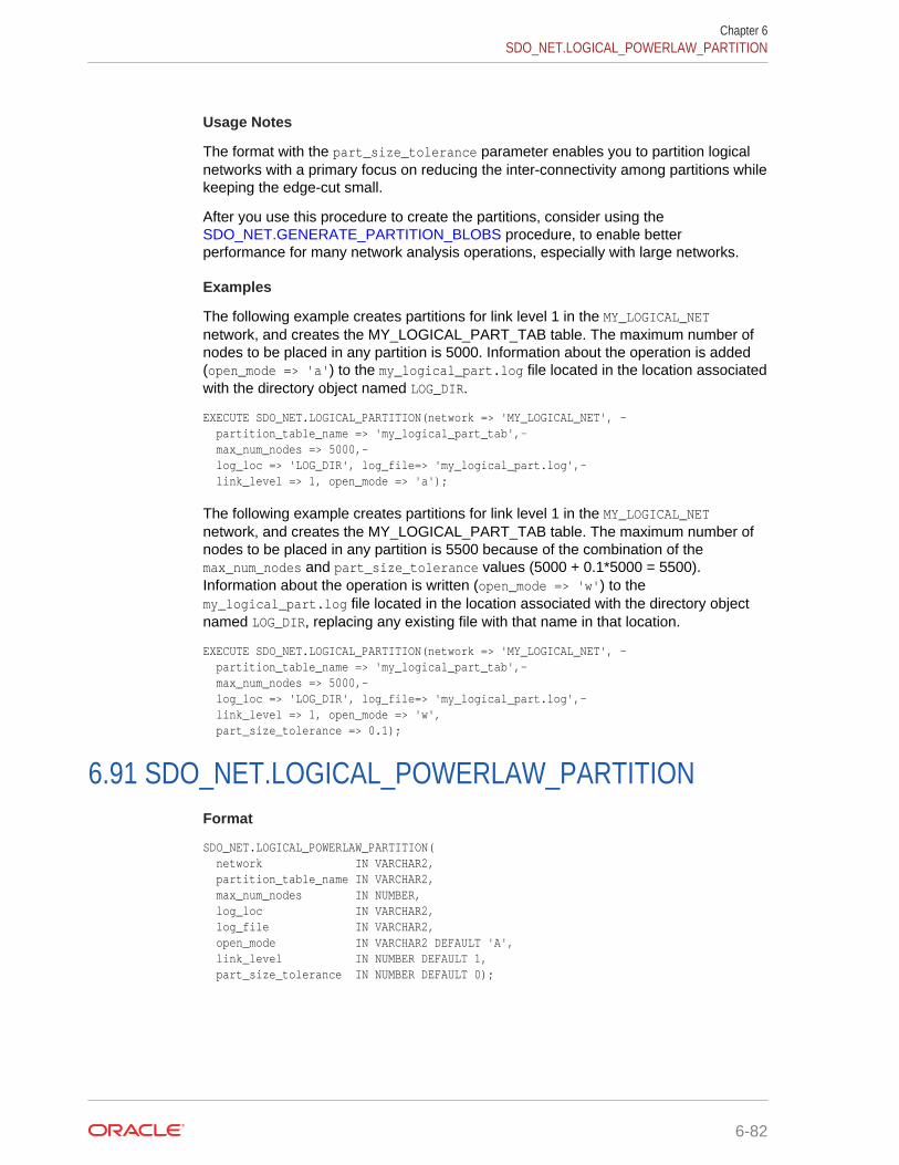
Usage Notes
The format with the part_size_tolerance parameter enables you to partition logicalnetworks with a primary focus on reducing the inter-connectivity among partitions whilekeeping the edge-cut small.
After you use this procedure to create the partitions, consider using the SDO_NET.GENERATE_PARTITION_BLOBS procedure, to enable betterperformance for many network analysis operations, especially with large networks.
Examples
The following example creates partitions for link level 1 in the MY_LOGICAL_NETnetwork, and creates the MY_LOGICAL_PART_TAB table. The maximum number ofnodes to be placed in any partition is 5000. Information about the operation is added(open_mode => 'a') to the my_logical_part.log file located in the location associatedwith the directory object named LOG_DIR.
EXECUTE SDO_NET.LOGICAL_PARTITION(network => 'MY_LOGICAL_NET', - partition_table_name => 'my_logical_part_tab',- max_num_nodes => 5000,- log_loc => 'LOG_DIR', log_file=> 'my_logical_part.log',- link_level => 1, open_mode => 'a');
The following example creates partitions for link level 1 in the MY_LOGICAL_NETnetwork, and creates the MY_LOGICAL_PART_TAB table. The maximum number ofnodes to be placed in any partition is 5500 because of the combination of themax_num_nodes and part_size_tolerance values (5000 + 0.1*5000 = 5500).Information about the operation is written (open_mode => 'w') to themy_logical_part.log file located in the location associated with the directory objectnamed LOG_DIR, replacing any existing file with that name in that location.
EXECUTE SDO_NET.LOGICAL_PARTITION(network => 'MY_LOGICAL_NET', - partition_table_name => 'my_logical_part_tab',- max_num_nodes => 5000,- log_loc => 'LOG_DIR', log_file=> 'my_logical_part.log',- link_level => 1, open_mode => 'w', part_size_tolerance => 0.1);
6.91 SDO_NET.LOGICAL_POWERLAW_PARTITIONFormat
SDO_NET.LOGICAL_POWERLAW_PARTITION( network IN VARCHAR2, partition_table_name IN VARCHAR2, max_num_nodes IN NUMBER, log_loc IN VARCHAR2, log_file IN VARCHAR2, open_mode IN VARCHAR2 DEFAULT 'A', link_level IN NUMBER DEFAULT 1, part_size_tolerance IN NUMBER DEFAULT 0);
Chapter 6SDO_NET.LOGICAL_POWERLAW_PARTITION
6-82

Description
Partitions a logical power law (also called scale-free) network, and stores theinformation in the partition table. (In a power law network, the node degree valuescontain the power law information.)
Parameters
networkNetwork name.
partition_table_nameName of the partition table, which is created by this procedure. (If an existing tablewith the specified name already exists, it is updated with partition information for thespecified link level.) The partition table is described in Partition Table.
max_num_nodesMaximum number of nodes to include in each partition. For example, if you specify5000 and if the network contains 50,000 nodes, each partition will have 5000 or fewernodes, and the total number of partitions will be 10 or higher.If the part_size_tolerance value is greater than 0, the maximum number of nodes toinclude in each partition is increased, as explained in the description of thatparameter.
log_locDirectory object that identifies the path for the log file. To create a directory object,use the SQL*Plus command CREATE DIRECTORY.
log_fileLog file containing information about operations on the logical power law network,including any possible errors or problems.
open_modeA one-character code indicating the mode in which to open the log file: W for write over(that is, delete any existing log file at the specified location and name, and create anew file), or A (the default) for append (that is, append information to the existingspecified log file). If you specify A and the log file does not exist, a new log file iscreated.
link_levelNetwork link level on which to perform the partitioning (default = 1). The link levelreflects the priority level for the link, and is used for network analysis, so that links withhigher priority levels can be considered first in computing a path.
part_size_toleranceAllowed tolerance in partition size expressed as a percentage of max_num_nodes. Mustbe from 0 (the default) to 100.A part_size_tolerance value greater than 0 effectively raises the max_num_nodesvalue. For example, if max_num_nodes is 5000 and you specify part_size_toleranceas 10, then the actual maximum number of nodes to include in each partition is 5500(5000 + 500, because 500 is 10 percent of 5000). In deciding whether to usepart_size_tolerance and what value to specify, consider the cache size and theprobability of related nodes being placed in different partitions.
Chapter 6SDO_NET.LOGICAL_POWERLAW_PARTITION
6-83
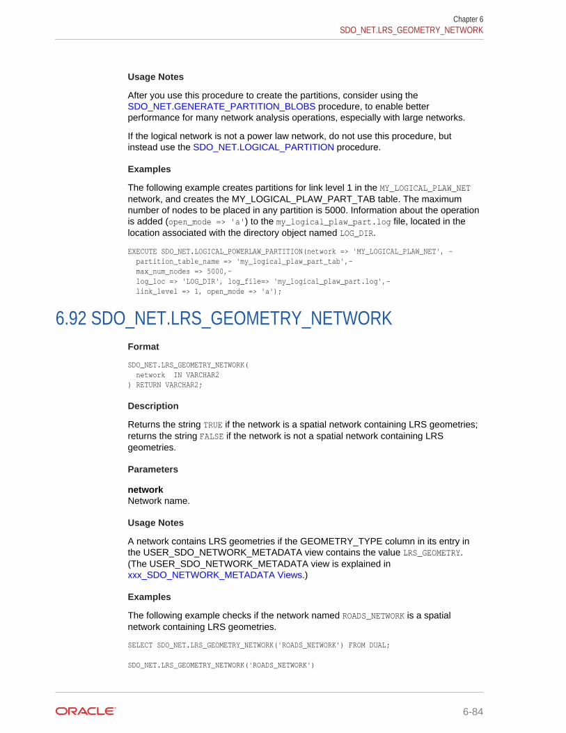
Usage Notes
After you use this procedure to create the partitions, consider using the SDO_NET.GENERATE_PARTITION_BLOBS procedure, to enable betterperformance for many network analysis operations, especially with large networks.
If the logical network is not a power law network, do not use this procedure, butinstead use the SDO_NET.LOGICAL_PARTITION procedure.
Examples
The following example creates partitions for link level 1 in the MY_LOGICAL_PLAW_NETnetwork, and creates the MY_LOGICAL_PLAW_PART_TAB table. The maximumnumber of nodes to be placed in any partition is 5000. Information about the operationis added (open_mode => 'a') to the my_logical_plaw_part.log file, located in thelocation associated with the directory object named LOG_DIR.
EXECUTE SDO_NET.LOGICAL_POWERLAW_PARTITION(network => 'MY_LOGICAL_PLAW_NET', - partition_table_name => 'my_logical_plaw_part_tab',- max_num_nodes => 5000,- log_loc => 'LOG_DIR', log_file=> 'my_logical_plaw_part.log',- link_level => 1, open_mode => 'a');
6.92 SDO_NET.LRS_GEOMETRY_NETWORKFormat
SDO_NET.LRS_GEOMETRY_NETWORK( network IN VARCHAR2 ) RETURN VARCHAR2;
Description
Returns the string TRUE if the network is a spatial network containing LRS geometries;returns the string FALSE if the network is not a spatial network containing LRSgeometries.
Parameters
networkNetwork name.
Usage Notes
A network contains LRS geometries if the GEOMETRY_TYPE column in its entry inthe USER_SDO_NETWORK_METADATA view contains the value LRS_GEOMETRY.(The USER_SDO_NETWORK_METADATA view is explained in xxx_SDO_NETWORK_METADATA Views.)
Examples
The following example checks if the network named ROADS_NETWORK is a spatialnetwork containing LRS geometries.
SELECT SDO_NET.LRS_GEOMETRY_NETWORK('ROADS_NETWORK') FROM DUAL; SDO_NET.LRS_GEOMETRY_NETWORK('ROADS_NETWORK')
Chapter 6SDO_NET.LRS_GEOMETRY_NETWORK
6-84
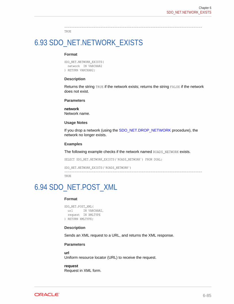
--------------------------------------------------------------------------------TRUE
6.93 SDO_NET.NETWORK_EXISTSFormat
SDO_NET.NETWORK_EXISTS( network IN VARCHAR2 ) RETURN VARCHAR2;
Description
Returns the string TRUE if the network exists; returns the string FALSE if the networkdoes not exist.
Parameters
networkNetwork name.
Usage Notes
If you drop a network (using the SDO_NET.DROP_NETWORK procedure), thenetwork no longer exists.
Examples
The following example checks if the network named ROADS_NETWORK exists.
SELECT SDO_NET.NETWORK_EXISTS('ROADS_NETWORK') FROM DUAL; SDO_NET.NETWORK_EXISTS('ROADS_NETWORK') --------------------------------------------------------------------------------TRUE
6.94 SDO_NET.POST_XMLFormat
SDO_NET.POST_XML( url IN VARCHAR2, request IN XMLTYPE ) RETURN XMLTYPE;
Description
Sends an XML request to a URL, and returns the XML response.
Parameters
urlUniform resource locator (URL) to receive the request.
requestRequest in XML form.
Chapter 6SDO_NET.NETWORK_EXISTS
6-85
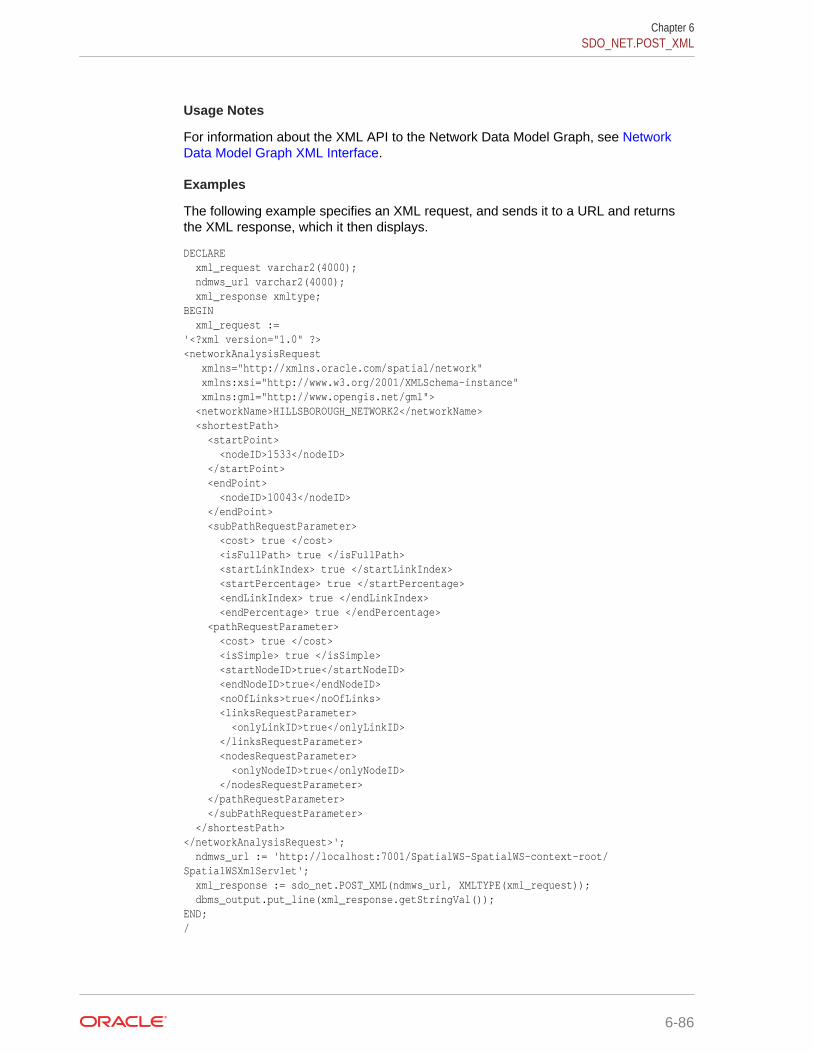
Usage Notes
For information about the XML API to the Network Data Model Graph, see NetworkData Model Graph XML Interface.
Examples
The following example specifies an XML request, and sends it to a URL and returnsthe XML response, which it then displays.
DECLARE xml_request varchar2(4000); ndmws_url varchar2(4000); xml_response xmltype;BEGIN xml_request :='<?xml version="1.0" ?><networkAnalysisRequest xmlns="http://xmlns.oracle.com/spatial/network" xmlns:xsi="http://www.w3.org/2001/XMLSchema-instance" xmlns:gml="http://www.opengis.net/gml"> <networkName>HILLSBOROUGH_NETWORK2</networkName> <shortestPath> <startPoint> <nodeID>1533</nodeID> </startPoint> <endPoint> <nodeID>10043</nodeID> </endPoint> <subPathRequestParameter> <cost> true </cost> <isFullPath> true </isFullPath> <startLinkIndex> true </startLinkIndex> <startPercentage> true </startPercentage> <endLinkIndex> true </endLinkIndex> <endPercentage> true </endPercentage> <pathRequestParameter> <cost> true </cost> <isSimple> true </isSimple> <startNodeID>true</startNodeID> <endNodeID>true</endNodeID> <noOfLinks>true</noOfLinks> <linksRequestParameter> <onlyLinkID>true</onlyLinkID> </linksRequestParameter> <nodesRequestParameter> <onlyNodeID>true</onlyNodeID> </nodesRequestParameter> </pathRequestParameter> </subPathRequestParameter> </shortestPath></networkAnalysisRequest>'; ndmws_url := 'http://localhost:7001/SpatialWS-SpatialWS-context-root/SpatialWSXmlServlet'; xml_response := sdo_net.POST_XML(ndmws_url, XMLTYPE(xml_request)); dbms_output.put_line(xml_response.getStringVal());END;/
Chapter 6SDO_NET.POST_XML
6-86
6.95 SDO_NET.REGISTER_CONSTRAINTFormat
SDO_NET.REGISTER_CONSTRAINT( constraint_name IN VARCHAR2, class_name IN VARCHAR2, directory_name IN VARCHAR2, description IN VARCHAR2);
Description
Loads the compiled Java code for the specified network constraint into the Java classrepository in the database, and loads the class name into the CLASS column of theUSER_SDO_NETWORK_CONSTRAINTS view (described in xxx_SDO_NETWORK_CONSTRAINTS Views).
Parameters
constraint_nameName of the network constraint.
class_nameFully qualified name (including the name of the package) of the class that implementsthe network constraint.
directory_nameName of the directory object (created using the SQL statement CREATEDIRECTORY) that identifies the location of the class file created when you compiledthe network constraint.
descriptionDescription of the network constraint.
Usage Notes
Before you call this procedure, you must insert a row into theUSER_SDO_NETWORK_CONSTRAINTS view, compile the code for the Java classthat implements the network constraint, and use the CREATE DIRECTORY statementto create a directory object identifying the location of the compiled class. For moreinformation about network constraints, see Network Constraints.
To delete the row for the constraint from theUSER_SDO_NETWORK_CONSTRAINTS view and thus disable the constraint, usethe SDO_NET.DEREGISTER_CONSTRAINT procedure.
Examples
The following example registers a network constraint named GivenProhibitedTurn.
-- Set up the network constraint.REMREM Create the geor_dir on the file system first.REM-- Connect as SYSTEM.DECLARE -- This is the directory that contains the CLASS file generated when you
Chapter 6SDO_NET.REGISTER_CONSTRAINT
6-87
-- compiled the network constraint. geor_dir varchar2(1000) := 'C:\my_data\files81\PROTOTYPES\NETWORK_CONSTRAINT\PLSQL_EXAMPLE';BEGIN EXECUTE IMMEDIATE 'CREATE OR REPLACE DIRECTORY work_dir AS''' || geor_dir || ''''; END;/GRANT read,write on directory work_dir to net_con; -- Connect as the user that will register the constraint. REMREM Compile GivenProhibitedTurn before you register the constraint.REMBEGIN SDO_NET.REGISTER_CONSTRAINT('GivenProhibitedTurn', 'com/network/constraints/ProhibitedTurn', 'WORK_DIR', 'This is a network constraint that '|| 'prohibits certain turns'); END;/
6.96 SDO_NET.SDO_GEOMETRY_NETWORKFormat
SDO_NET.SDO_GEOMETRY_NETWORK( network IN VARCHAR2 ) RETURN VARCHAR2;
Description
Returns the string TRUE if the network is a spatial network containing SDO geometries(spatial geometries without measure information); returns the string FALSE if thenetwork is not a spatial network containing SDO geometries.
Parameters
networkNetwork name.
Usage Notes
A network contains SDO geometries if the GEOMETRY_TYPE column in its entry inthe USER_SDO_NETWORK_METADATA view contains the value SDO_GEOMETRY.(The USER_SDO_NETWORK_METADATA view is explained in xxx_SDO_NETWORK_METADATA Views.)
Examples
The following example checks if the network named ROADS_NETWORK is a spatialnetwork containing SDO geometries.
SELECT SDO_NET.SDO_GEOMETRY_NETWORK('ROADS_NETWORK') FROM DUAL; SDO_NET.SDO_GEOMETRY_NETWORK('ROADS_NETWORK') --------------------------------------------------------------------------------FALSE
Chapter 6SDO_NET.SDO_GEOMETRY_NETWORK
6-88

6.97 SDO_NET.SET_LOGGING_LEVELFormat
SDO_NET.SET_LOGGING_LEVEL( level IN NUMBER);
Description
Sets the minimum level of severity for messages to be displayed for networkoperations.
Parameters
levelMinimum severity level for messages to be displayed for network operations. Must beone of the numeric constants specified in the Usage Notes.
Usage Notes
All messages at the specified logging level and higher levels will be written. Thelogging levels, from highest to lowest, are:
SDO_NET.LOGGING_LEVEL_FATALSDO_NET.LOGGING_LEVEL_ERRORSDO_NET.LOGGING_LEVEL_WARNSDO_NET.LOGGING_LEVEL_INFOSDO_NET.LOGGING_LEVEL_DEBUGSDO_NET.LOGGING_LEVEL_FINEST
The logging level is the Java logging level from the underlying implementation of thisfunction; therefore, to see the Java logging output on the console, execute thefollowing statements beforehand:
SET SERVEROUTPUT ON;EXECUTE DBMS_JAVA.SET_OUTPUT(10000);
Examples
The following example sets the logging level at SDO_NET.LOGGING_LEVEL_ERROR, whichmeans that only messages with a severity of SDO_NET.LOGGING_LEVEL_ERROR orSDO_NET.LOGGING_LEVEL_FATAL will be displayed.
EXECUTE SDO_NET.SET_LOGGING_LEVEL(SDO_NET.LOGGING_LEVEL_ERROR);
6.98 SDO_NET.SET_MAX_JAVA_HEAP_SIZEFormat
SDO_NET.SET_MAX_JAVA_HEAP_SIZE( bytes IN NUMBER);
Description
Sets the Java maximum heap size for an application to run in an Oracle Java virtualmachine.
Chapter 6SDO_NET.SET_LOGGING_LEVEL
6-89
Parameters
bytesNumber of bytes for the Java maximum heap size.
Usage Notes
If you encounter the java.lang.OutOfMemoryError exception, you can use thisprocedure to increase the maximum heap size.
If you specify a value greater than the system limit, the system limit is used.
Examples
The following example sets the Java maximum heap size to 536870912 (512 MB).
EXECUTE SDO_NET.SET_MAX_JAVA_HEAP_SIZE(536870912);
6.99 SDO_NET.SPATIAL_PARTITIONFormat
SDO_NET.SPATIAL_PARTITION( network IN VARCHAR2, partition_table_name IN VARCHAR2, max_num_nodes IN NUMBER, log_loc IN VARCHAR2, log_file IN VARCHAR2, open_mode IN VARCHAR2 DEFAULT 'A', link_level IN NUMBER DEFAULT 1);
Description
Partitions a spatial network, and stores the information in the partition table.
Parameters
networkNetwork name.
partition_table_nameName of the partition table, which is created by this procedure. (If an existing tablewith the specified name already exists, it is updated with partition information for thespecified link level.) The partition table is described in Partition Table.
max_num_nodesMaximum number of nodes to include in each partition. For example, if you specify5000 and if the network contains 50,000 nodes, each partition will have 5000 or fewernodes, and the total number of partitions will be 10 or higher.
log_locDirectory object that identifies the path for the log file. To create a directory object,use the SQL*Plus command CREATE DIRECTORY.
Chapter 6SDO_NET.SPATIAL_PARTITION
6-90

log_fileLog file containing information about spatial network operations, including anypossible errors or problems.
open_modeA one-character code indicating the mode in which to open the log file: W for write over(that is, delete any existing log file at the specified location and name, and create anew file), or A (the default) for append (that is, append information to the existingspecified log file). If you specify A and the log file does not exist, a new log file iscreated.
link_levelNetwork link level on which to perform the partitioning (default = 1). The link levelreflects the priority level for the link, and is used for network analysis, so that links withhigher priority levels can be considered first in network computations.
Usage Notes
After you use this procedure to create the partitions, consider using the SDO_NET.GENERATE_PARTITION_BLOBS procedure, to enable betterperformance for many network analysis operations, especially with large networks.
Examples
The following example creates partitions for link level 1 in the MY_PARTITIONED_NETnetwork, and creates the MY_PARTITIONED_NET_TAB table. The maximum numberof nodes to be placed in any partition is 5000. Information about the operation is added(open_mode => 'a') to the my_partitioned_net.log file, located in the locationassociated with the directory object named LOG_DIR.
EXECUTE SDO_NET.SPATIAL_PARTITION(network => 'MY_PARTITIONED_NET', - partition_table_name => 'my_partitioned_net_tab',- max_num_nodes => 5000,- log_loc => 'LOG_DIR', log_file=> 'my_partitioned_net.log',- link_level => 1, open_mode => 'a');
6.100 SDO_NET.TOPO_GEOMETRY_NETWORKFormat
SDO_NET.TOPO_GEOMETRY_NETWORK( network IN VARCHAR2 ) RETURN VARCHAR2;
Description
Returns the string TRUE if the network is a spatial network containingSDO_TOPO_GEOMETRY (topology geometry) objects; returns the string FALSE if thenetwork is not a spatial network containing SDO_TOPO_GEOMETRY objects.
Parameters
networkNetwork name.
Chapter 6SDO_NET.TOPO_GEOMETRY_NETWORK
6-91
Usage Notes
A network contains SDO_TOPO_GEOMETRY objects if the GEOMETRY_TYPEcolumn in its entry in the USER_SDO_NETWORK_METADATA view contains thevalue TOPO_GEOMETRY. (The USER_SDO_NETWORK_METADATA view is explained in xxx_SDO_NETWORK_METADATA Views.)
Examples
The following example checks if the network named ROADS_NETWORK is a spatialnetwork containing SDO_TOPO_GEOMETRY objects.
SELECT SDO_NET.TOPO_GEOMETRY_NETWORK('ROADS_NETWORK') FROM DUAL; SDO_NET.TOPO_GEOMETRY_NETWORK('ROADS_NETWORK') --------------------------------------------------------------------------------FALSE
6.101 SDO_NET.UPDATE_FEATUREFormat
SDO_NET.UPDATE_FEATURE( feature_layer_id IN NUMBER, feature_id IN NUMBER, feature_elements IN SDO_NET_FEAT_ELEM_ARRAY DEFAULT NULL, child_feature_ids IN SDO_NET_LAYER_FEAT_ARRAY DEFAULT NULL, check_integrity IN BOOLEAN DEFAULT TRUE);
Description
Updates a feature in a feature layer.
Parameters
feature_layer_idID of the feature layer to which to update the feature.
feature_idID of the feature to be updated.
feature_elementsFeature elements of the feature to add to any existing feature elements. If thisparameter is null, the existing feature elements are not changed. If this parameter inempty, any existing feature elements are removed. (TheSDO_NET_FEAT_ELEM_ARRAY type is described in Data Types Used for FeatureModeling.)
child_feature_idsChild features of the feature that are to add to any existing child features. If thisparameter is null, the existing child features are not changed. If this parameter inempty, any existing parent relationships for this feature with child features areremoved. (The SDO_NET_LAYER_FEAT_ARRAY type is described in Data TypesUsed for Feature Modeling.)
Chapter 6SDO_NET.UPDATE_FEATURE
6-92
check_integrityTRUE (the default) checks if the input network elements exist; and if any do not exist,an error is generated. FALSE does not check if the input network elements exist.
Usage Notes
To add a feature to a feature layer, use the SDO_NET.ADD_FEATURE procedure.
A feature layer ID is automatically generated for the feature layer.
Examples
The following example updates a specified feature by defining two feature elementsand adding them.
DECLARE feature_layer_id NUMBER; feature_id NUMBER := 1; elements SDO_NET_FEAT_ELEM_ARRAY := SDO_NET_FEAT_ELEM_ARRAY(); link_id NUMBER := 1314;BEGIN feature_layer_id := sdo_net.get_feature_layer_id('GRID', 'POI'); elements.extend; elements(1) := SDO_NET_FEAT_ELEM(SDO_NET.FEAT_ELEM_TYPE_POL, link_id, 0.7, null); elements.extend; elements(2) := SDO_NET_FEAT_ELEM(SDO_NET.FEAT_ELEM_TYPE_POL, link_id, 0.8, null); sdo_net.update_feature(feature_layer_id, feature_id, elements, null);END;/
6.102 SDO_NET.UPDATE_FEATURE_ELEMENTFormat
SDO_NET.UPDATE_FEATURE_ELEMENT( feature_layer_id IN NUMBER, feature_id IN NUMBER, sequence_number IN NUMBER, feature_element IN SDO_NET_FEAT_ELEM, check_integrity IN BOOLEAN DEFAULT TRUE);
Description
Updates a feature element.
Parameters
feature_layer_idID of the feature layer for the feature.
feature_idID of the feature.
sequence_numberSequence number of the feature element to be updated.
Chapter 6SDO_NET.UPDATE_FEATURE_ELEMENT
6-93
feature_elementFeature element definition to replace the specified feature element. (TheSDO_NET_FEAT_ELEM type is described in Data Types Used for Feature Modeling.)
check_integrityTRUE (the default) checks if the input network elements exist; and if any do not exist,an error is generated. FALSE does not check if the input network elements exist.
Usage Notes
To add a feature element, use the SDO_NET.ADD_FEATURE_ELEMENT procedure;to add multiple feature elements in a single operation, use the SDO_NET.ADD_FEATURE_ELEMENTS procedure.
Examples
The following example updates the feature element at sequence number 2 on link ID1314 of feature ID 1.
DECLARE feature_layer_id NUMBER; feature_id NUMBER := 1; element SDO_NET_FEAT_ELEM; link_id NUMBER := 1314;BEGIN feature_layer_id := sdo_net.get_feature_layer_id('GRID', 'POI'); element := SDO_NET_FEAT_ELEM(SDO_NET.FEAT_ELEM_TYPE_POL, link_id, 0.2, null); sdo_net.update_feature_element(feature_layer_id, feature_id, 1, element);END;/
6.103 SDO_NET.VALIDATE_LINK_SCHEMAFormat
SDO_NET.VALIDATE_LINK_SCHEMA( network IN VARCHAR2 ) RETURN VARCHAR2;
Description
Returns the string TRUE if the metadata relating to links in a network is valid; returnsthe string FALSE if the metadata relating to links in a network is not valid.
Parameters
networkNetwork name.
Usage Notes
This function checks the following for validity: table name, geometry column, and costcolumn for spatial networks; measure-related information for LRS networks; topology-related information for topology networks; and hierarchy-related information forhierarchical networks.
Chapter 6SDO_NET.VALIDATE_LINK_SCHEMA
6-94

Examples
The following example checks the validity of the metadata related to links in thenetwork named ROADS_NETWORK.
SELECT SDO_NET.VALIDATE_LINK_SCHEMA('ROADS_NETWORK') FROM DUAL; SDO_NET.VALIDATE_LINK_SCHEMA('ROADS_NETWORK') --------------------------------------------------------------------------------TRUE
6.104 SDO_NET.VALIDATE_LRS_SCHEMAFormat
SDO_NET.VALIDATE_LRS_SCHEMA( network IN VARCHAR2 ) RETURN VARCHAR2;
Description
Returns the string TRUE if the metadata relating to LRS information in a network isvalid; returns the string FALSE if the metadata relating to LRS information in a networkis not valid.
Parameters
networkNetwork name.
Usage Notes
None.
Examples
The following example checks the validity of the metadata related to LRS informationin the network named ROADS_NETWORK.
SELECT SDO_NET.VALIDATE_LRS_SCHEMA('ROADS_NETWORK') FROM DUAL; SDO_NET.VALIDATE_LRS_SCHEMA('ROADS_NETWORK') --------------------------------------------------------------------------------TRUE
6.105 SDO_NET.VALIDATE_NETWORKFormat
SDO_NET.VALIDATE_NETWORK( network IN VARCHAR2, check_data IN VARCHAR2 DEFAULT 'FALSE' ) RETURN VARCHAR2;
Chapter 6SDO_NET.VALIDATE_LRS_SCHEMA
6-95
Description
Returns the string TRUE if the network is valid; returns the string FALSE if the network isnot valid.
Parameters
networkNetwork name.
check_dataTRUE performs additional checks on the referential integrity of network data; FALSE (thedefault) performs basic checks, but not additional checks, on the referential integrity ofnetwork data.
Usage Notes
This function checks the metadata for the network and any applicable network schemastructures (link, node, path, subpath, LRS). It performs basic referential integritychecks on the network data, and it optionally performs additional checks. If any errorsare found, the function returns the string FALSE.
The checks performed by this function include the following:
• The network exists.
• The node and link tables for the network exist, and they contain the requiredcolumns.
• The start and end nodes of each link exist in the node table.
• For an LRS geometry network, the LRS table exists and contains the requiredcolumns.
• For a spatial network, columns for the node and path geometries exist and havespatial indexes defined on them.
• If check_data is TRUE, additional referential integrity checking on the network datais performed. This will take longer, especially if the network is large.
Examples
The following example validates the network named LOG_NET1.
SELECT SDO_NET.VALIDATE_NETWORK('LOG_NET1') FROM DUAL; SDO_NET.VALIDATE_NETWORK('LOG_NET1')--------------------------------------------------------------------------------TRUE
6.106 SDO_NET.VALIDATE_NODE_SCHEMAFormat
SDO_NET.VALIDATE_NODE_SCHEMA( network IN VARCHAR2 ) RETURN VARCHAR2;
Chapter 6SDO_NET.VALIDATE_NODE_SCHEMA
6-96
Description
Returns the string TRUE if the metadata relating to nodes in a network is valid; returnsthe string FALSE if the metadata relating to nodes in a network is not valid.
Parameters
networkNetwork name.
Usage Notes
This function checks the following for validity: table name, geometry column, and costcolumn for spatial networks; measure-related information for LRS networks; topology-related information for topology networks; and hierarchy-related information forhierarchical networks.
Examples
The following example checks the validity of the metadata related to nodes in thenetwork named LOG_NET1.
SELECT SDO_NET.VALIDATE_NODE_SCHEMA('LOG_NET1') FROM DUAL; SDO_NET.VALIDATE_NODE_SCHEMA('LOG_NET1')--------------------------------------------------------------------------------TRUE
6.107 SDO_NET.VALIDATE_PARTITION_SCHEMAFormat
SDO_NET.VALIDATE_PARTITION_SCHEMA( network IN VARCHAR2 ) RETURN VARCHAR2;
Description
Returns the string TRUE if the metadata relating to partitions in a network is valid;returns the string FALSE if the metadata relating to partitions in a network is not valid.
Parameters
networkNetwork name.
Usage Notes
This function checks the validity of information in the partition table, which is describedin Partition Table.
Examples
The following example checks the validity of the metadata related to partitions in thenetwork named SDO_PARTITIONED.
Chapter 6SDO_NET.VALIDATE_PARTITION_SCHEMA
6-97

SELECT SDO_NET.VALIDATE_PARTITION_SCHEMA('SDO_PARTITIONED') FROM DUAL; SDO_NET.VALIDATE_PARTITION_SCHEMA('SDO_PARTITIONED')--------------------------------------------------------------------------------TRUE
6.108 SDO_NET.VALIDATE_PATH_SCHEMAFormat
SDO_NET.VALIDATE_PATH_SCHEMA( network IN VARCHAR2 ) RETURN VARCHAR2;
Description
Returns the string TRUE if the metadata relating to paths in a network is valid; returnsthe string FALSE if the metadata relating to paths in a network is not valid.
Parameters
networkNetwork name.
Usage Notes
This function checks the following for validity: table name, geometry column, and costcolumn for spatial networks; measure-related information for LRS networks; topology-related information for topology networks; and hierarchy-related information forhierarchical networks.
Examples
The following example checks the validity of the metadata related to paths in thenetwork named ROADS_NETWORK.
SELECT SDO_NET.VALIDATE_PATH_SCHEMA('ROADS_NETWORK') FROM DUAL; SDO_NET.VALIDATE_PATH_SCHEMA('ROADS_NETWORK') --------------------------------------------------------------------------------TRUE
6.109 SDO_NET.VALIDATE_SUBPATH_SCHEMAFormat
SDO_NET.VALIDATE_SUBPATH_SCHEMA( network IN VARCHAR2 ) RETURN VARCHAR2;
Description
Returns the string TRUE if the metadata relating to subpaths in a network is valid;returns the string FALSE if the metadata relating to subpaths in a network is not valid.
Chapter 6SDO_NET.VALIDATE_PATH_SCHEMA
6-98

Parameters
networkNetwork name.
Usage Notes
This function checks the validity of information in the subpath table, which is describedin Subpath Table.
Examples
The following example checks the validity of the metadata related to subpaths in thenetwork named MY_NETWORK.
SELECT SDO_NET.VALIDATE_SUBPATH_SCHEMA('MY_NETWORK') FROM DUAL; SDO_NET.VALIDATE_SUBPATH_SCHEMA('MY_NETWORK')--------------------------------------------------------------------------------TRUE
Chapter 6SDO_NET.VALIDATE_SUBPATH_SCHEMA
6-99
7SDO_NFE Package Subprograms
The MDSYS.SDO_NFE package contains subprograms (functions and procedures) forperforming network feature editing.
To use these subprograms, you must understand the conceptual information in Network Data Model Graph Overview, and especially Feature Modeling Using NetworkFeature Editing (NFE).
• SDO_NFE.APPLY_RULE
• SDO_NFE.CLASSIFY_LINES_BY_SIDE
• SDO_NFE.CREATE_MODEL_SEQUENCE
• SDO_NFE.CREATE_MODEL_STRUCTURE
• SDO_NFE.CREATE_MODEL_UNDERLYING_NET
• SDO_NFE.CREATE_MODEL_WORKSPACE
• SDO_NFE.DELETE_ALL_FT_LAYERS
• SDO_NFE.DELETE_ALL_WORKSPACES
• SDO_NFE.DELETE_MODEL_STRUCTURE
• SDO_NFE.DELETE_MODEL_WORKSPACE
• SDO_NFE.DROP_MODEL_SEQUENCE
• SDO_NFE.DROP_MODEL_UNDERLYING_NETWORK
• SDO_NFE.GET_CONNECTION_POINT_GEOM
• SDO_NFE.GET_INTERACTION_GROUPS
• SDO_NFE.GET_LINES_MATCH_LP_RULE
• SDO_NFE.GET_LL_CONN_INTERSECTIONS
• SDO_NFE.GET_LP_CONN_INTERSECTIONS
• SDO_NFE.GET_MODEL_SEQUENCE_NAME
• SDO_NFE.GET_MODEL_TABLE_NAME
• SDO_NFE.GET_MODEL_UNDERLYING_NETWORK
• SDO_NFE.GET_NEXT_SEQUENCE_VALUE
• SDO_NFE.GET_POINTS_MATCH_LP_RULE
• SDO_NFE.IMPORT_NETWORK
• SDO_NFE.SET_MODEL_UNDERLYING_NETWORK
7-1
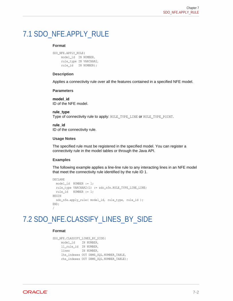
7.1 SDO_NFE.APPLY_RULEFormat
SDO_NFE.APPLY_RULE( model_id IN NUMBER, rule_type IN VARCHAR2, rule_id IN NUMBER);
Description
Applies a connectivity rule over all the features contained in a specified NFE model.
Parameters
model_idID of the NFE model.
rule_typeType of connectivity rule to apply: RULE_TYPE_LINE or RULE_TYPE_POINT.
rule_idID of the connectivity rule.
Usage Notes
The specified rule must be registered in the specified model. You can register aconnectivity rule in the model tables or through the Java API.
Examples
The following example applies a line-line rule to any interacting lines in an NFE modelthat meet the connectivity rule identified by the rule ID 1.
DECLARE model_id NUMBER := 1; rule_type VARCHAR2(1) := sdo_nfe.RULE_TYPE_LINE_LINE; rule_id NUMBER := 1;BEGIN sdo_nfe.apply_rule( model_id, rule_type, rule_id );END;/
7.2 SDO_NFE.CLASSIFY_LINES_BY_SIDEFormat
SDO_NFE.CLASSIFY_LINES_BY_SIDE( model_id IN NUMBER, ll_rule_id IN NUMBER, lines IN NUMBER, lhs_indexes OUT DBMS_SQL,NUMBER_TABLE, rhs_indexes OUT DBMS_SQL,NUMBER_TABLE);
Chapter 7SDO_NFE.APPLY_RULE
7-2
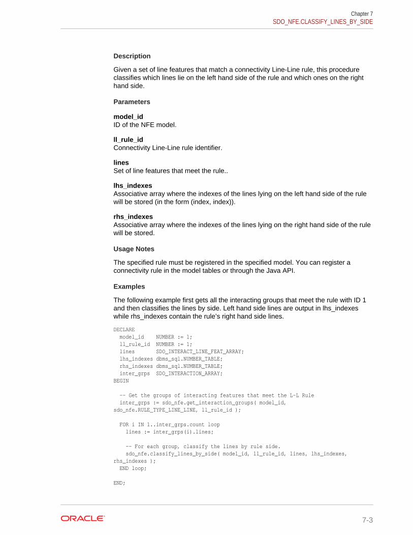
Description
Given a set of line features that match a connectivity Line-Line rule, this procedureclassifies which lines lie on the left hand side of the rule and which ones on the righthand side.
Parameters
model_idID of the NFE model.
ll_rule_idConnectivity Line-Line rule identifier.
linesSet of line features that meet the rule..
lhs_indexesAssociative array where the indexes of the lines lying on the left hand side of the rulewill be stored (in the form (index, index)).
rhs_indexesAssociative array where the indexes of the lines lying on the right hand side of the rulewill be stored.
Usage Notes
The specified rule must be registered in the specified model. You can register aconnectivity rule in the model tables or through the Java API.
Examples
The following example first gets all the interacting groups that meet the rule with ID 1and then classifies the lines by side. Left hand side lines are output in lhs_indexeswhile rhs_indexes contain the rule’s right hand side lines.
DECLARE model_id NUMBER := 1; ll_rule_id NUMBER := 1; lines SDO_INTERACT_LINE_FEAT_ARRAY; lhs_indexes dbms_sql.NUMBER_TABLE; rhs_indexes dbms_sql.NUMBER_TABLE; inter_grps SDO_INTERACTION_ARRAY;BEGIN
-- Get the groups of interacting features that meet the L-L Rule inter_grps := sdo_nfe.get_interaction_groups( model_id, sdo_nfe.RULE_TYPE_LINE_LINE, ll_rule_id );
FOR i IN 1..inter_grps.count loop lines := inter_grps(i).lines;
-- For each group, classify the lines by rule side. sdo_nfe.classify_lines_by_side( model_id, ll_rule_id, lines, lhs_indexes, rhs_indexes ); END loop;
END;
Chapter 7SDO_NFE.CLASSIFY_LINES_BY_SIDE
7-3
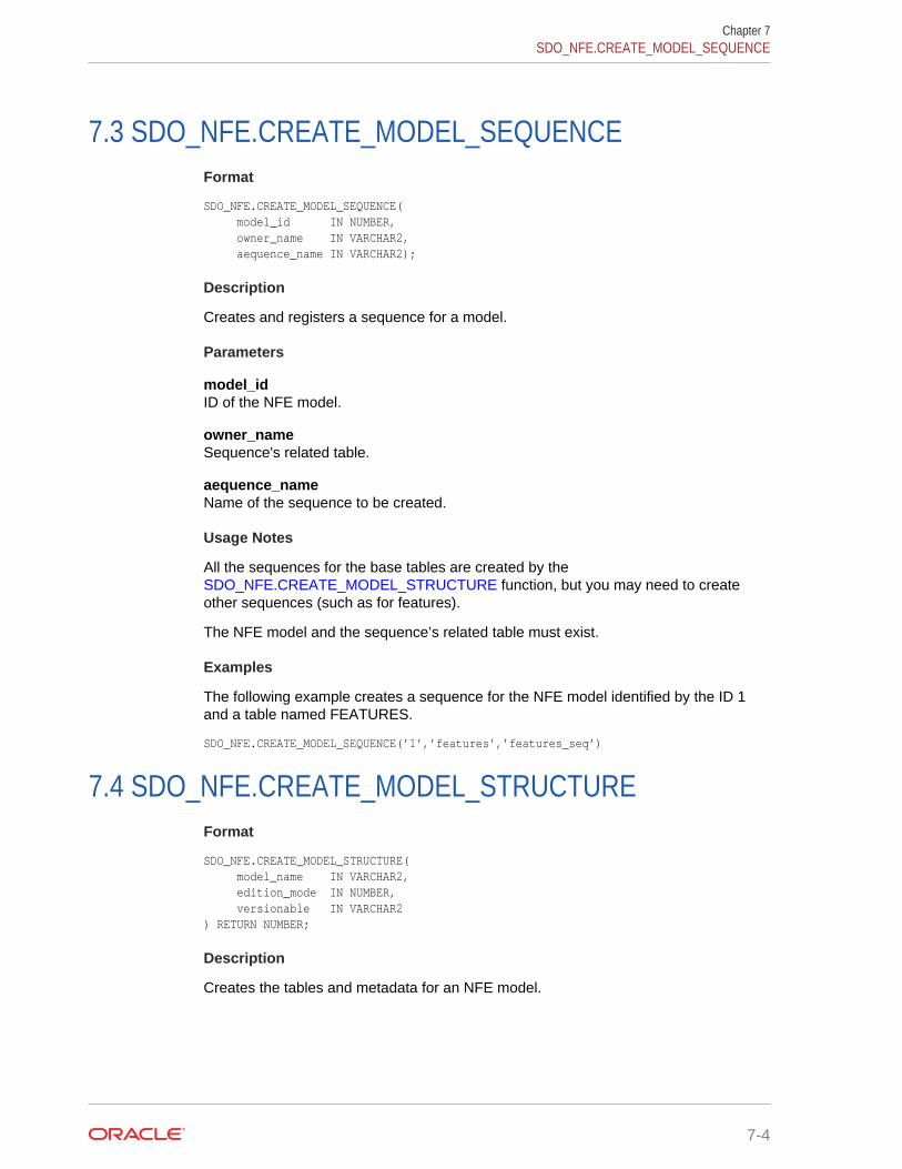
7.3 SDO_NFE.CREATE_MODEL_SEQUENCEFormat
SDO_NFE.CREATE_MODEL_SEQUENCE( model_id IN NUMBER, owner_name IN VARCHAR2, aequence_name IN VARCHAR2);
Description
Creates and registers a sequence for a model.
Parameters
model_idID of the NFE model.
owner_nameSequence's related table.
aequence_nameName of the sequence to be created.
Usage Notes
All the sequences for the base tables are created by the SDO_NFE.CREATE_MODEL_STRUCTURE function, but you may need to createother sequences (such as for features).
The NFE model and the sequence’s related table must exist.
Examples
The following example creates a sequence for the NFE model identified by the ID 1and a table named FEATURES.
SDO_NFE.CREATE_MODEL_SEQUENCE(’1’,’features’,’features_seq’)
7.4 SDO_NFE.CREATE_MODEL_STRUCTUREFormat
SDO_NFE.CREATE_MODEL_STRUCTURE( model_name IN VARCHAR2, edition_mode IN NUMBER, versionable IN VARCHAR2) RETURN NUMBER;
Description
Creates the tables and metadata for an NFE model.
Chapter 7SDO_NFE.CREATE_MODEL_SEQUENCE
7-4
Parameters
model_nameName to be given to the lNFE model.
edition_modeEdition mode. Must be SDO_NFE.FROM_SCRATCH or SDO_NFE.OVER_EXIST_NETWORK.
versionableThe string value Y if the model will be versionable, otherwise N.
Usage Notes
This function returns the new model's ID value.
Examples
The following example creates a versionable model named MODEL01 with theSDO_NFE.FROM_SCRATCH edition mode.
DECLARE model_id NUMBER; model_name VARCHAR2(50) := 'MODEL01'; edition_mode NUMBER := SDO_NFE.FROM_SCRATCH; versionable VARCHAR2(1) := 'Y';BEGIN model_id := SDO_NFE.create_model_structure( model_name, edition_mode, versionable );END;/
7.5 SDO_NFE.CREATE_MODEL_UNDERLYING_NETFormat
SDO_NFE.CREATE_MODEL_UNDERLYING_NET( model_id IN NUMBER, network_name IN VARCHAR2, num_hierarchy_levels IN NUMBER, is_directed IN BOOLDEAN, node_with_costs IN BOOLEAN);
Description
Creates a spatial network and associates it to the specified NFE Model. It also createssequences for its nodes, links, and paths, and registers them in the model's metadata.
Parameters
model_idID of the NFE model.
network_nameName of the network to be created.
Chapter 7SDO_NFE.CREATE_MODEL_UNDERLYING_NET
7-5
num_hierarchy_levelsNumber of hierarchical levels for the network.
is_directedTRUE if the network is directed.
node_with_costsTRUE if the network’s nodes contain cost values.
Usage Notes
An NFE model with the specified ID must exist. The geometry metadata must beregistered for the newly created network’s nodes and links tables.
Examples
The following example creates an underlying network for an NFE model and registersthe geometry metadata for the network’s links and nodes tables.
DECLARE model_id NUMBER := 1; network_name VARCHAR2(50) := 'MODEL01'; num_hierarchy_levels NUMBER := 1; is_directed VARCHAR2(10) := 'TRUE'; node_with_costs VARCHAR2(10) := 'TRUE';BEGIN-- create underlying network SDO_NFE.create_model_underlying_net( model_id, network_name, num_hierarchy_levels, is_directed, node_with_costs );-- register links and nodes tables geom metadata SDO_NET.insert_geom_metadata(network_name, SDO_DIM_ARRAY(SDO_DIM_ELEMENT('LONGITUDE', -180, 180, 0.5), SDO_DIM_ELEMENT('LATITUDE', -90, 90, 0.5)), 8307);END;/
7.6 SDO_NFE.CREATE_MODEL_WORKSPACEFormat
SDO_NFE.CREATE_MODEL_WORKSPACE( model_id IN NUMBER, parent_workspace_name IN VARCHAR2, workspace_name IN VARCHAR2, is_mbr IN VARCHAR2, is_locked IN VARCHAR2, lower_x IN NUMBER, lower_y IN NUMBER, upper_x IN NUMBER, upper_y IN NUMBER);
Description
Creates a new workspace and relates it to an NFE model.
Chapter 7SDO_NFE.CREATE_MODEL_WORKSPACE
7-6
Parameters
model_idID of the NFE model.
parent_workspace_nameName of the parent workspace.
workspace_nameName of the workspace.
is_mbrThe string TRUE if the workspace is created for a minimum bounding rectangle (MBR)rectangular area of the model.
is_lockedThe string TRUE if the workspace is locked.
lower_xThe lower x ordinate of the workspace MBR.
lower_yThe lower y ordinate of the workspace MBR.
upper_xThe upper x ordinate of the workspace MBR.
upper_yThe upper y ordinate of the workspace MBR.
Usage Notes
The NFE model must have been created with the versionable option enabled.
Examples
The following example creates a workspace for an NFE model.
DECLARE model_id NUMBER := 1; parent_ws_name VARCHAR2(30) := 'LIVE'; workspace_name VARCHAR2(30) := 'PROJECT_V1'; is_mbr VARCHAR2(1) := 'Y'; is_locked VARCHAR2(1) := 'N'; lower_x NUMBER := -15.575; lower_y NUMBER := 15.575; upper_x NUMBER := -12.825; upper_y NUMBER := 28.975;BEGIN SDO_NFE.create_model_workspace(model_id, parent_ws_name, workspace_name, is_mbr, is_locked, lower_x, lower_y, upper_x, upper_y);END;/
Chapter 7SDO_NFE.CREATE_MODEL_WORKSPACE
7-7
7.7 SDO_NFE.DELETE_ALL_FT_LAYERSFormat
SDO_NFE.DELETE_ALL_FT_LAYERS( model_id IN NUMBER);
Description
Drops all content in a specified NFE model.
Parameters
model_idID of the NFE model.
Usage Notes
This procedure is mainly used before deleting a model and its structure from thedatabase.
Examples
The following example deletes all content from the model with the ID value 1.
EXECUTE SDO_NFE.DELETE_ALL_FT_LAYERS(1);
7.8 SDO_NFE.DELETE_ALL_WORKSPACESFormat
SDO_NFE.DELETE_ALL_WORKSPACES( model_id IN NUMBER);
Description
Dropa all the workspaces related to the specified NFE model, along with theirrelationship to the model.
Parameters
model_idID of the NFE model.
Usage Notes
This procedure is mainly used before deleting a model and its structure from thedatabase.
Examples
The following example deletes all workspaces related to the model with ID value 1.
EXECUTE SDO_NFE.DELETE_ALL_WORKSPACES(1);
Chapter 7SDO_NFE.DELETE_ALL_FT_LAYERS
7-8

7.9 SDO_NFE.DELETE_MODEL_STRUCTUREFormat
SDO_NFE.DELETE_MODEL_STRUCTURE( model_id IN NUMBER);
Description
Drops all tables in a specified NFE model, and deletes the metadata records for themodel.
Parameters
model_idID of the NFE model.
Usage Notes
Before using this procedure, you may need to do the following:
• Delete model’s workspaces by executing the SDO_NFE.DELETE_ALL_WORKSPACES procedure.
• Delete the model’s feature layers by executing the SDO_NFE.DELETE_ALL_FT_LAYERS procedure.
• If f the model’s edition mode is SDO_NFE.FROM_SCRATCH, delete the underlyingnetwork.
Examples
The following example the structure of the model with the ID value 1.
EXECUTE SDO_NFE.DELETE_MODEL_STRUCTURE(1);
7.10 SDO_NFE.DELETE_MODEL_WORKSPACEFormat
SDO_NFE.DELETE_MODEL_WORKSPACE( model_id IN NUMBER, workspace_name IN VARCHAR2);
Description
Drops a workspace along with its relationship with the specified NFE model.
Parameters
model_idID of the NFE model.
workspace_nameName of the workspace.
Chapter 7SDO_NFE.DELETE_MODEL_STRUCTURE
7-9

Usage Notes
workspace_name must be the name of an existing workspace under the specified NFEmodel. All branches of the workspace are removed.
The relationship with the model is deleted fromxxx_SDO_NFE_MODEL_WORKSPACE views.
Examples
The following example deletes the workspace named PROJECT_V4 from the NFE modelwith the ID 1
EXECUTE SDO_NFE.DELETE_MODEL_WORKSPACE(1, 'PROJECT_V4');
7.11 SDO_NFE.DROP_MODEL_SEQUENCEFormat
SDO_NFE.DROP_MODEL_SEQUENCE( model_id IN NUMBER, seq_name IN VARCHAR2);
Description
Drops a sequence along with its relationship with the specified NFE model.
Parameters
model_idID of the NFE model.
seq_nameName of the sequence.
Usage Notes
The relationship of the sequence with the model is deleted from the table registered inSEQUENCE_REG_TAB from the xxx_SDO_NFE_MODEL_METADATA views.
Examples
The following example deletes the sequence named PIPES_FTLAY_ID_SEQ from theNFE model with the ID 1.
EXECUTE SDO_NFE.DROP_MODEL_SEQUENCE(1, 'PIPES_FTLAY_ID_SEQ');
7.12SDO_NFE.DROP_MODEL_UNDERLYING_NETWORK
Format
SDO_NFE.DROP_MODEL_UNDERLYING_NETWORK network_name IN VARCHAR2);
Chapter 7SDO_NFE.DROP_MODEL_SEQUENCE
7-10
Description
Drops a network and removes its relationship with any NFE model.
Parameters
network_nameName of the network.
Usage Notes
The network must be bound to at least one NFE model..
Examples
The following example drops the network named PIPES and removes its relationshipwith any existing NFE model.
EXECUTE SDO_NFE.DROP_MODEL_UNDERLYING_NETWORK('PIPES');
7.13 SDO_NFE.GET_CONNECTION_POINT_GEOMFormat
SDO_NFE.GET_CONNECTION_POINT_GEOM( conn_intersection IN SDO_INTERACTION ) RETURN SDO_GEOMETRY;
Description
Given a group of interacting features (lines and/or points), calculates and returns thegeometry of the point that must connect them.
Parameters
conn_intersectionInteraction group of features. Set of line and/or point features that interact at acommon spatial point. (The SDO_INTERACTION type is described in Data TypesUsed for NFE Connectivity Rules.)
Usage Notes
This function is mainly used over a validated group of features that must be connectedbecause of the requirement of a connectivity rule (see NFE Rules). To get this groupof features, use SDO_NFE.GET_LP_CONN_INTERSECTIONS for Line-Point Rulesor SDO_NFE.GET_LL_CONN_INTERSECTIONS for Line-Line Rules.
Examples
The following example gets the connection point geometry for each interacting groupthat meets the given line-point rule.
DECLARE model_id NUMBER := 1; lp_rule_id NUMBER := 1; inter_grps SDO_INTERACTION_ARRAY; conn_point_geom SDO_GEOMETRY;
Chapter 7SDO_NFE.GET_CONNECTION_POINT_GEOM
7-11
BEGIN -- Get the groups of interacting features that meet the L-P Rule in the model inter_grps := sdo_nfe.get_interaction_groups( model_id, sdo_nfe.RULE_TYPE_LINE_POINT, lp_rule_id ); -- Iterate through the interacting groups FOR i IN 1..inter_grps.count loop -- Get the connection point geometry for each interacting group conn_point_geom := sdo_nfe.get_connection_point_geom( inter_groups(i)); END loop;END;/
7.14 SDO_NFE.GET_INTERACTION_GROUPSFormat
SDO_NFE.GET_INTERACTION_GROUPS( model_id IN SDO_NUMBER, rule_type IN VARCHAR2, rule_id IN NUMBER ) RETURN SDO_INTERACTION_ARRAY;
Description
Returns an array of groups of all features that are interacting at spatial points wherethe specified connectivity rule is being met.
Parameters
model_idNFE model identifier.
rule_typeConnectivity rule type. Possible values: SDO_NFE.RULE_TYPE_LINE_LINE orSDO_NFE.RULE_TYPE_LINE_POINT.
rule_idRule identifier. Must be a value from the LINE_LINE_RULE or LINE_POINT_RULEtable.
Usage Notes
This function returns an object of type SDO_INTERACTION_ARRAY, which isdescribed in Data Types Used for NFE Connectivity Rules.
Each group of the interacting features returned by this function is composed of all theline and point features that interact at a specific spatial point where the specified rule isbeing met.
By returning the whole group of all interacting features at specific points, this functioncan help you if you want to create a customized way of connecting features dependingon which other features (meeting the rule or not) are taking part in a specifiedinteraction point. (See the discussion of rule decision handlers under NFE Rules.)
Examples
The following example gets the interacting groups which met the given line-point rule.
Chapter 7SDO_NFE.GET_INTERACTION_GROUPS
7-12
DECLARE model_id NUMBER := 1; lp_rule_id NUMBER := 1; inter_grps SDO_INTERACTION_ARRAY;BEGIN inter_grps := sdo_nfe.get_interaction_groups( model_id, END;/
7.15 SDO_NFE.GET_LINES_MATCH_LP_RULEFormat
SDO_NFE.GET_LINES_MATCH_LP_RULE( model_id IN SDO_NUMBER, lp_rule_id IN NUMBER, lines IN SDO_INTERACT_LINE_FEAT_ARRAY, ) RETURN DBMS_SQL.NUMBER_TABLE;
Description
Given an set of line features, calculates the group of them that match a connectivityline-point rule. Returns a DBMS_SQL.NUMBER_TABLE object with the indexes of thelines in the input array that match the line-point rule.
Parameters
model_idNFE model identifier.
lp_rule_idConnectivity line-point rule identifier. Must exist in the LINE_POINT_RULE table.
linesArray of line features where the search will take place. (TheSDO_INTERACT_LINE_FEAT_ARRAY type is described in Data Types Used forNFE Connectivity Rules.)
Usage Notes
This function is mainly used after the SDO_NFE.GET_INTERACTION_GROUPSfunction, which returned a group of mixed line features where some line featuresmatched a specific connectivity rule and some did not.
Examples
The following example finds the lines that meet a connectivity line-point rule frominteracting groups.
DECLARE model_id NUMBER := 1; lp_rule_id NUMBER := 1; lines SDO_INTERACT_LINE_FEAT_ARRAY; match_lines dbms_sql.NUMBER_TABLE; inter_grps SDO_INTERACTION_ARRAY;BEGIN -- find interaction groups inter_grps := sdo_nfe.get_interaction_groups( model_id, sdo_nfe.RULE_TYPE_LINE_LINE, 1 );
Chapter 7SDO_NFE.GET_LINES_MATCH_LP_RULE
7-13

FOR i IN 1..inter_grps.count loop lines := inter_grps(i).lines; match_lines := sdo_nfe.get_lines_match_lp_rule( model_id, lp_rule_id, lines ); END loop;
END;/
7.16 SDO_NFE.GET_LL_CONN_INTERSECTIONSFormat
SDO_NFE.GET_LL_CONN_INTERSECTIONS( model_id IN SDO_NUMBER, ll_rule_id IN NUMBER, interaction_grp IN OUT SDO_INTERACTION, rule_lhs_lines_indexes IN DBMS_SQL.NUMBER_TABLE, rule_rhs_lines_indexes IN DBMS_SQL.NUMBER_TABLE, rule_points_indexes IN DBMS_SQL.NUMBER_TABLE, ) RETURN SDO_INTERACTION_ARRAY;
Description
Given a group of interacting features (lines and points) this function calculatessubgroups of these features that can be connected according to the connectivity line-line rule specified, and returns the set of connectable features groups.
Parameters
model_idNFE model identifier.
ll_rule_idConnectivity line-line rule identifier.. Must exist in the LINE_LINE_RULE table.
interaction_grpGroup of interacting features. (The SDO_INTERACTION type is described in DataTypes Used for NFE Connectivity Rules.)
rule_lhs_lines_indexesAmong the line features in the interacting group, indexes of the lines that match theleft hand side of the line-line rule.
rule_rhs_lines_indexesAmong the line features in the interacting group, indexes of the lines that match theright hand side of the line-line rule.
rule_points_indexesAmong the point features in the interacting group, indexes of the points that match thepoint feature specification in the line-line rule. These points are the ones to beconsidered in the conformation of connectable groups.
Usage Notes
This function returns an SDO_INTERACTION_ARRAY object. (TheSDO_INTERACTION_ARRAY type is described in Data Types Used for NFEConnectivity Rules.)
Chapter 7SDO_NFE.GET_LL_CONN_INTERSECTIONS
7-14
The indexes of LHS and RHS lines can be obtained with the SDO_NFE.CLASSIFY_LINES_BY_SIDE procedure. The indexes of the points can beobtained with the SDO_NFE.GET_POINTS_MATCH_LP_RULE function.
This function is registered by default in the Rule Decision Handlers Table when a line-line rule is created in a model (using the Java API). However, this function can bereplaced by any other user function that calculates the group of connectable featuresin a customized way. See the information about Rule Decision Handlers under NFERules for information about customizing connections (rule decision handlers).
Examples
The following example gets the set of connectable feature groups for each interactinggroup that match a given line-line rule.
DECLARE model_id NUMBER := 1; ll_rule_id NUMBER := 1; rule_lhs_lines_indexes dbms_sql.NUMBER_TABLE; rule_rhs_lines_indexes dbms_sql.NUMBER_TABLE; rule_points_indexes dbms_sql.NUMBER_TABLE; conn_interacs SDO_INTERACTION_ARRAY; inter_grps SDO_INTERACTION_ARRAY;BEGIN -- Get the groups of interacting features that meet the L-L Rule in the model inter_grps := sdo_nfe.get_interaction_groups( model_id, sdo_nfe.RULE_TYPE_LINE_LINE, ll_rule_id ); FOR i IN 1..inter_grps.count loop -- Classify the line features by side in the L-L rule (LHS, RHS). sdo_nfe.classify_lines_by_side( model_id, ll_rule_id, inter_grps(i).lines, rule_lhs_lines_indexes, rule_rhs_lines_indexes ); -- Get the specific point features that match the L-L rule. rule_points_indexes := sdo_nfe.get_points_match_lp_rule( model_id, 1, inter_grps(i).points ); -- Get the group of features that can be connected according the L-L rule. conn_interacs := sdo_nfe.get_ll_conn_intersections( model_id, ll_rule_id, inter_grps(i), rule_lhs_lines_indexes, rule_rhs_lines_indexes, rule_points_indexes); END loop;END; /
7.17 SDO_NFE.GET_LP_CONN_INTERSECTIONSFormat
SDO_NFE.GET_LP_CONN_INTERSECTIONS( model_id IN SDO_NUMBER, lp_rule_id IN NUMBER, interaction_grp IN OUT SDO_INTERACTION, rule_lhs_lines_indexes IN DBMS_SQL.NUMBER_TABLE, rule_rhs_lines_indexes IN DBMS_SQL.NUMBER_TABLE, rule_points_indexes IN DBMS_SQL.NUMBER_TABLE, ) RETURN SDO_INTERACTION_ARRAY;
Description
Given a group of interacting features (lines and points) this function calculatessubgroups of these features that can be connected according to the connectivity line-point rule specified, and returns the set of connectable features groups.
Chapter 7SDO_NFE.GET_LP_CONN_INTERSECTIONS
7-15
Parameters
model_idNFE model identifier.
lp_rule_idConnectivity line-point rule identifier.. Must exist in the LINE_POINT_RULE table.
interaction_grpGroup of interacting features. (The SDO_INTERACTION type is described in DataTypes Used for NFE Connectivity Rules.)
rule_lhs_lines_indexesAmong the line features in the interacting group, indexes of the lines that match theleft hand side of the line-point rule.
rule_rhs_lines_indexesAmong the line features in the interacting group, indexes of the lines that match theright hand side of the line-point rule.
rule_points_indexesAmong the point features in the interacting group, indexes of the points that match thepoint feature specification in the line-point rule. These points are the ones to beconsidered in the conformation of connectable groups.
Usage Notes
This function returns an SDO_INTERACTION_ARRAY object. (TheSDO_INTERACTION_ARRAY type is described in Data Types Used for NFEConnectivity Rules.)
The indexes of LHS and RHS lines can be obtained with the SDO_NFE.CLASSIFY_LINES_BY_SIDE procedure. The indexes of the points can beobtained with the SDO_NFE.GET_POINTS_MATCH_LP_RULE function.
This function is registered by default in the Rule Decision Handlers Table when a line-point rule is created in a model (using the Java API). However, this function can bereplaced by any other user function that calculates the group of connectable featuresin a customized way. See the information about Rule Decision Handlers under NFERules for information about customizing connections (rule decision handlers).
Examples
The following example gets the group of feature that can be connected according to agiven line-point rule for each interacting group.
DECLARE model_id NUMBER := 1; lp_rule_id NUMBER := 1; rule_lines_indexes dbms_sql.NUMBER_TABLE; rule_points_indexes dbms_sql.NUMBER_TABLE; conn_interacs SDO_INTERACTION_ARRAY; inter_grps SDO_INTERACTION_ARRAY;BEGIN -- Get the groups of interacting features that meet the L-P Rule in the model inter_grps := sdo_nfe.get_interaction_groups( model_id, sdo_nfe.RULE_TYPE_LINE_POINT, lp_rule_id );
Chapter 7SDO_NFE.GET_LP_CONN_INTERSECTIONS
7-16
-- For each group: FOR i IN 1..inter_grps.count loop -- Get the specific line features that match the L-P rule. rule_lines_indexes := sdo_nfe.get_lines_match_lp_rule( model_id, lp_rule_id, inter_grps(i).lines );
-- Get the specific point features that match the L-P rule. rule_points_indexes := sdo_nfe.get_points_match_lp_rule( model_id, lp_rule_id, inter_grps(i).points );
-- Get the group of features that can be connected according the L-P rule. conn_interacs := sdo_nfe.get_lp_conn_intersections( model_id, lp_rule_id, inter_grps(i), rule_lines_indexes, rule_points_indexes ); END loop;END;/
7.18 SDO_NFE.GET_MODEL_SEQUENCE_NAMEFormat
SDO_NFE.GET_MODEL_SEQUENCE_NAME( model_id IN SDO_NUMBER, tab_name IN VARCHAR2 ) RETURN VARCHAR2;
Description
Returns the sequence name for the specified model’s table.
Parameters
model_idNFE model identifier.
tab_nameTable name for the model.
Usage Notes
The table name must exist in the TABLE_REG_TAB table, and the name of itssequence must exist in the SEQUENCE_REG_TAB table. When a new model iscreated using SDO_NFE.CREATE_MODEL_STRUCTURE, all the model’s tables andsequences are automatically registered in the appropriate views and tables. When SDO_NFE.CREATE_MODEL_SEQUENCEis executed, a sequence for the model’stable is registered.
Examples
The following example gets the sequence name defined for the table that holds thefeature classes of the NFE model whose ID is 1.
SELECT SDO_NFE.GET_MODEL_SEQUENCE_NAME(1, sdo_nfe.get_model_table_name(1, SDO_NFE.FT_CLASS));
Chapter 7SDO_NFE.GET_MODEL_SEQUENCE_NAME
7-17

7.19 SDO_NFE.GET_MODEL_TABLE_NAMEFormat
SDO_NFE.GET_MODEL_TABLE_NAME( model_id IN SDO_NUMBER, table_type IN VARCHAR2 ) RETURN VARCHAR2;
Description
Returns the name of the table of a specified type for an NFE model.
Parameters
model_idNFE model identifier.
table_typeType of table whose name is to be returned. For example, the value for the featureclasses table is SDO_NFE.FT_CLASS.
Usage Notes
The table name must exist in the TABLE_REG_TAB table, and the name of itssequence must exist in the SEQUENCE_REG_TAB table. When a new model iscreated using SDO_NFE.CREATE_MODEL_STRUCTURE, the names of all of themodel’s tables and sequences are automatically registered in the appropriate viewsand tables.
Examples
The following example gets the name of the table that holds the feature classes in theNFE model with the ID 1.
SELECT SDO_NFE.GET_MODEL_TABLE_NAME(1, SDO_NFE.FT_CLASS);
7.20 SDO_NFE.GET_MODEL_UNDERLYING_NETWORKFormat
SDO_NFE.GET_MODEL_UNDERLYING_NETWORK( model_id IN SDO_NUMBER ) RETURN VARCHAR2;
Description
Returns the name of the network that is associated with an NFE model.
Parameters
model_idNFE model identifier.
Chapter 7SDO_NFE.GET_MODEL_TABLE_NAME
7-18
Usage Notes
A network is associated with an NFE model during the creation process, either whenusing the SDO_NFE.CREATE_MODEL_UNDERLYING_NET for models in theSDO_NFE.FROM_SCRATCH mode, or using SDO_NFE.SET_MODEL_UNDERLYING_NETWORK for models in theSDO_NFE.OVER_EXIST_NETWORK mode.
Examples
The following example gets the underlying network associated with an existing NFEmodel.
SELECT SDO_NFE.get_model_underlying_network(1) FROM DUAL;
7.21 SDO_NFE.GET_NEXT_SEQUENCE_VALUEFormat
SDO_NFE.GET_NEXT_SEQUENCE_VALUE( sequence_name IN VARCHAR2, seq_value_increment IN NUMBER ) RETURN NUMBER;
Description
Returns the value resulting from adding the value of the second parameter to thecurrent value of the specified sequence.
Parameters
sequence_nameName of the sequence.
seq_value_incrementInteger value to be added to the current value of sequence_name. (If the specifiedvalue is negative, it is subtracted from the current value.)
Usage Notes
This function does not change the INCREMENT BY value of the specified sequence orthe current value of that sequence.
This function can be used to manage a block of consecutive sequence numbers.
Examples
The following example returns the value that would result from adding 10 to the currentvalue of a sequence named MY_SEQ.
SELECT SDO_NFE.GET_NEXT_SEQUENCE_VALUE('my_seq', 10) FROM DUAL;
If the current value of MY_SEQ is 100, this example returns the value 110 (100 + 10).
Chapter 7SDO_NFE.GET_NEXT_SEQUENCE_VALUE
7-19
7.22 SDO_NFE.GET_POINTS_MATCH_LP_RULEFormat
SDO_NFE.GET_POINTS_MATCH_LP_RULE( model_id IN SDO_NUMBER, lp_rule_id IN NUMBER, points IN SDO_INTERACT_POINT_FEAT_ARRAY, ) RETURN DBMS_SQL.NUMBER_TABLE;
Description
Given an set of point features, this function calculates the group of them that match aconnectivity line-point rule. Returns a DBMS_SQL.NUMBER_TABLE object with theindexes of the points in the input array that match the line-point rule.
Parameters
model_idNFE model identifier.
lp_rule_idConnectivity line-point rule identifier. Must exist in the LINE_POINT_RULE table.
pointsArray of point features where the search will take place. (TheSDO_INTERACT_POINT_FEAT_ARRAY type is described in Data Types Used forNFE Connectivity Rules.)
Usage Notes
This function is mainly used after the SDO_NFE.GET_INTERACTION_GROUPSfunction, which returned a group of mixed line features where some line featuresmatched a specific connectivity rule and some did not.
Examples
The following example gets the specific point features that match a line-point rule.
DECLARE model_id NUMBER := 1; lp_rule_id NUMBER := 1; rule_points_indexes dbms_sql.NUMBER_TABLE; inter_grps SDO_INTERACTION_ARRAY;BEGIN -- Get the groups of interacting features that meet the L-P Rule in the model inter_grps := sdo_nfe.get_interaction_groups( model_id, sdo_nfe.RULE_TYPE_LINE_POINT, lp_rule_id );
-- For each group: FOR i IN 1..inter_grps.count loop -- Get the specific point features that match the L-P rule. rule_points_indexes := sdo_nfe.get_points_match_lp_rule( model_id, lp_rule_id, inter_grps(i).points ); END loop;END;/
Chapter 7SDO_NFE.GET_POINTS_MATCH_LP_RULE
7-20
7.23 SDO_NFE.IMPORT_NETWORKFormat
SDO_NFE.IMPORT_NETWORK( model_id IN NUMBER, model_id IN NUMBER, network_from IN VARCHAR2, line_ft_layer_id IN NUMBER, line_ft_class_id IN NUMBER, point_ft_layer_id IN NUMBER, point_ft_class_id IN NUMBER);
Description
Copies the network elements from an existing network to the underlying network of anNFE model (created in the SDO_NFE.FROM_SCRATCH mode), translating every linkin line features from the line feature class (line_ft_class_id), and every node in pointfeatures from the point feature class (point_ft_class_id)..
Parameters
model_idNFE model identifier.
network_fromName of the network to be imported.
line_ft_layer_idFeature layer ID for the newly created line features (created from the link elements).
line_ft_class_idFeature class ID for the newly created line features.
point_ft_layer_idFeature layer ID for the newly created point features (created from the nodeelements).
point_ft_class_idFeature class ID for the newly created point features.
Usage Notes
The feature classes for the line and point features must already exist in the NFEmodel.
Examples
The following example imports a network named NET01 to a model identified by the ID1. Lines and point features will be created for every link and node using the featurelayers 10 and 11 and the feature classes 5 and 6.
EXECUTE SDO_NFE.import_network(1, ‘NET01’, 10, 5, 11, 6);
Chapter 7SDO_NFE.IMPORT_NETWORK
7-21
7.24 SDO_NFE.SET_MODEL_UNDERLYING_NETWORKFormat
SDO_NFE.SET_MODEL_UNDERLYING_NETWORK( model_id IN SDO_NUMBER network_name IN VARCHAR2);
Description
Associates a network as the underlying network of an NFE model. (The model musthave been created in the SDO_NFE.OVER_EXIST_NETWORK mode.)
Parameters
model_idNFE model identifier.
network_nameName of the network to be associated with the model.
Usage Notes
See also the SDO_NFE.GET_MODEL_UNDERLYING_NETWORK function.
Examples
The following example ....
EXECUTE ... ;
Chapter 7SDO_NFE.SET_MODEL_UNDERLYING_NETWORK
7-22
Index
Aactive links, 5-5
ACTIVE column in link table, 5-31active nodes, 5-5
ACTIVE column in node table, 5-30ADD_CHILD_FEATURE procedure, 6-4ADD_CHILD_FEATURES procedure, 6-5ADD_EDGE function, 4-2ADD_FEATURE procedure, 6-6ADD_FEATURE_ELEMENT procedure, 6-7ADD_FEATURE_ELEMENTS procedure, 6-8ADD_FEATURE_LAYER procedure, 6-9ADD_ISOLATED_NODE function, 4-4ADD_LINEAR_GEOMETRY function, 4-5ADD_LOOP function, 4-7ADD_NODE function, 4-8ADD_POINT_GEOMETRY function, 4-10ADD_POLYGON_GEOMETRY function, 4-11ADD_TOPO_GEOMETRY_LAYER procedure,
3-1ALL_SDO_NETWORK_CONSTRAINTS view,
5-55ALL_SDO_NETWORK_METADATA view, 5-51ALL_SDO_NETWORK_USER_DATA view, 5-56,
5-58ALL_SDO_NFE_MODEL_FTLAYER_REL view,
5-59ALL_SDO_NFE_MODEL_METADATA view,
5-60ALL_SDO_NFE_MODEL_WORKSPACE view,
5-63ALL_SDO_TOPO_INFO view, 1-30ALL_SDO_TOPO_METADATA view, 1-31API
Network Data Model Graph, 5-64performance, 5-64
Topology Data Model, 1-33application programming interface (API)
Network Data Model Graphperformance, 5-64
Topology Data Model, 1-33APPLY_RULE procedure, 7-2
automatically created points default attributestable
definition, 5-42
Ccache, 2-2
partition, 5-28TopoMap object associated with, 2-2
See also TopoMap objectsCHANGE_EDGE_COORDS procedure, 4-12child layer, 1-11child node, 5-12CLASSIFY_LINES_BY_SIDE procedure, 7-2CLEAR_TOPO_MAP procedure, 4-14collection layers, 1-9COMMIT_TOPO_MAP procedure, 4-15complex path, 5-33COMPUTE_PATH_GEOMETRY procedure, 6-10connected component table
definition, 5-37connected components
finding, 6-39connectivity line-line rules table
definition, 5-42connectivity line-point rules table
definition, 5-43constraints
network, 5-26containing face
getting for point, 4-23COPY_NETWORK procedure, 6-11cost, 5-5
LINK_COST_COLUMN column in networkmetadata views, 5-53
NODE_COST_COLUMN column in networkmetadata views, 5-52
CREATE_EDGE_INDEX procedure, 4-16CREATE_FACE_INDEX procedure, 4-16CREATE_FEATURE function, 4-17CREATE_LINK_TABLE procedure, 6-12CREATE_LOGICAL_NETWORK procedure,
6-13CREATE_LRS_NETWORK procedure, 6-15CREATE_LRS_TABLE procedure, 6-18
Index-1
CREATE_MODEL_SEQUENCE procedure, 7-4CREATE_MODEL_STRUCTURE function, 7-4CREATE_MODEL_UNDERLYING_NET
procedure, 7-5CREATE_MODEL_WORKSPACE procedure,
7-6CREATE_NODE_TABLE procedure, 6-19CREATE_PARTITION_TABLE procedure, 6-20CREATE_PATH_LINK_TABLE procedure, 6-21CREATE_PATH_TABLE procedure, 6-21CREATE_SDO_NETWORK procedure, 6-22CREATE_SUBPATH_TABLE procedure, 6-25CREATE_TOPO_MAP procedure, 4-21CREATE_TOPO_NETWORK procedure, 6-26CREATE_TOPOLOGY procedure, 3-3cross-schema considerations
topology editing, 1-39topology usage, 1-39
Ddangling features
deleting, 6-30getting, 6-48
dangling linksdeleting, 6-31getting, 6-49
dangling nodesdeleting, 6-31getting, 6-49
degreeof a node, 5-5
DELETE_ALL_FT_LAYERS procedure, 7-8DELETE_ALL_WORKSPACES procedure, 7-8DELETE_CHILD_FEATURES procedure, 6-28DELETE_CHILD_FEATURES_AT procedure,
6-29DELETE_DANGLING_FEATURES procedure,
6-30DELETE_DANGLING_LINKS procedure, 6-31DELETE_DANGLING_NODES procedure, 6-31DELETE_FEATURE_ELEMENTS procedure,
6-32DELETE_FEATURE_ELEMENTS_AT
procedure, 6-33DELETE_FEATURES procedure, 6-33DELETE_LINK procedure, 6-34DELETE_MODEL_STRUCTURE procedure, 7-9DELETE_MODEL_WORKSPACE procedure, 7-9DELETE_NODE procedure, 6-35DELETE_PATH procedure, 6-36DELETE_PHANTOM_FEATURES procedure,
6-36DELETE_SUBPATH procedure, 6-37
DELETE_TOPO_GEOMETRY_LAYERprocedure, 3-5
demo filesNetwork Data Model Graph, 5-94
DEREGISTER_CONSTRAINT procedure, 6-37directed links, 5-5directed networks, 5-6direction of edge, 1-5DROP_MODEL_SEQUENCE procedure, 7-10DROP_MODEL_UNDERLYING_NETWORK
procedure, 7-10DROP_NETWORK procedure, 6-39DROP_TOPO_MAP procedure, 4-22DROP_TOPOLOGY procedure, 3-6duration, 5-5
LINK_DURATION_COLUMN column innetwork metadata views, 5-53
NODE_DURATION_COLUMN column innetwork metadata views, 5-53
Eedge index
creating for TopoMap object, 4-16edge information table, 1-15edge sequences
privileges needed for cross-schema topologyediting, 1-39
edgesadding, 2-16, 4-2adding linear geometry, 4-5adding loop, 4-7changing coordinates, 2-18, 4-12definition, 1-4direction, 1-5finding edges interacting with a query
window, 4-54getting coordinates of shape points, 4-25getting ID numbers of added edges, 4-24getting ID numbers of changed edges, 4-25getting ID numbers of deleted edges, 4-26getting nearest edge for point, 4-31getting nearest edge in cache for point, 4-32getting nodes on, 4-27island, 1-4isolated, 1-4loop, 1-4moving, 2-16, 4-46removing, 2-17, 4-51storing information in edge information table,
1-15updating, 2-18
error handlingtopology editing, 2-7
Index
Index-2
examplesNetwork Data Model Graph, 5-70, 5-94Topology Data Model (PL/SQL), 1-40
exception handlingtopology editing, 2-7
FF0 (face zero, or universe face), 1-4face index
creating for TopoMap object, 4-16face information table, 1-18face sequences
privileges needed for cross-schema topologyediting, 1-39
facesadding polygon geometry, 4-11definition, 1-4finding faces interacting with a query window,
4-55getting boundary, 4-29getting boundary of, 3-6getting containing face for point, 4-23getting ID numbers of added faces, 4-28getting ID numbers of changed faces, 4-29getting ID numbers of deleted faces, 4-30redefining, 2-18storing information in face information table,
1-18feature class attributes constraints table
definition, 5-44feature class default predefined connected points
tabledefinition, 5-45
feature class relationship tabledefinition, 5-45
feature class tabledefinition, 5-44
feature element relationships tabledefinition, 5-40
feature elements, 5-8definition, 5-8
feature hierarchy tabledefinition, 5-40
feature layer types, 5-8feature layers, 5-8feature rule relationship table
definition, 5-46feature table, 1-8
definition, 5-39feature types, 5-8feature user data catalog table
definition, 5-47feature user data catalog values table
definition, 5-47
feature user data tabledefinition, 5-46
FEATURE_LAYER procedure, 6-38features
creating from geometries, 4-17in network application, 5-6, 5-7in network applications, 5-8
FIND_CONNECTED_COMPONENTSprocedure, 6-39
function-based indexesnot supported on SDO_TOPO_GEOMETRY
columns, 1-40
GGENERATE_NODE_LEVELS procedure, 6-40GENERATE_PARTITION_BLOB procedure,
6-42GENERATE_PARTITION_BLOBS procedure,
6-44geometry
computing for a path, 6-10GET_CHILD_FEATURE_IDS function, 6-46GET_CHILD_LINKS function, 6-47GET_CHILD_NODES function, 6-47GET_CONNECTION_POINT_GEOM function,
7-11GET_CONTAINING_FACE function, 4-23GET_DANGLING_FEATURES function
SDO_NET packageGET_DANGLING_FEATURES, 6-48
GET_DANGLING_LINKS function, 6-49GET_DANGLING_NODES function, 6-49GET_EDGE_ADDITIONS function, 4-24GET_EDGE_CHANGES function, 4-25GET_EDGE_COORDS function, 4-25GET_EDGE_DELETIONS function, 4-26GET_EDGE_NODES function, 4-27GET_FACE_ADDITIONS function, 4-28GET_FACE_BOUNDARY function, 3-6, 4-29GET_FACE_CHANGES function, 4-29GET_FACE_DELETIONS function, 4-30GET_FEATURE_ELEMENTS function, 6-50GET_FEATURE_LAYER_ID function, 6-51GET_FEATURES_ON_LINKS function
SDO_NET packageGET_FEATURES_ON_LINKS, 6-51
GET_FEATURES_ON_NODES functionSDO_NET package
GET_FEATURES_ON_NODES, 6-52GET_GEOMETRY member function, 1-28GET_GEOMETRY_TYPE function, 6-53GET_IN_LINKS function, 6-54GET_INTERACTION_GROUPS function, 7-12GET_INVALID_LINKS function, 6-54
Index
3
GET_INVALID_NODES function, 6-55GET_INVALID_PATHS function, 6-55GET_ISOLATED_NODES function, 6-56GET_LINES_MATCH_LP_RULE function, 7-13GET_LINK_COST_COLUMN function, 6-56GET_LINK_DIRECTION function, 6-57GET_LINK_GEOM_COLUMN function, 6-58GET_LINK_GEOMETRY function, 6-58GET_LINK_TABLE_NAME function, 6-59GET_LINKS_IN_PATH function, 6-60GET_LL_CONN_INTERSECTIONS function,
7-14GET_LP_CONN_INTERSECTIONS function,
7-15GET_LRS_GEOM_COLUMN function, 6-60GET_LRS_LINK_GEOMETRY function, 6-61GET_LRS_NODE_GEOMETRY function, 6-62GET_LRS_TABLE_NAME function, 6-62GET_MODEL_SEQUENCE_NAME function,
7-17GET_MODEL_TABLE_NAME function, 7-18GET_MODEL_UNDERLYING_NETWORK
function, 7-18GET_NEAREST_EDGE function, 4-31GET_NEAREST_EDGE_IN_CACHE function,
4-32GET_NEAREST_NODE function, 4-33GET_NEAREST_NODE_IN_CACHE function,
4-35GET_NETWORK_TYPE function, 6-63GET_NEXT_SEQUENCE_VALUE function, 7-19GET_NO_OF_HIERARCHY_LEVELS function,
6-64GET_NO_OF_LINKS function, 6-64GET_NO_OF_NODES function, 6-65GET_NODE_ADDITIONS function, 4-36GET_NODE_CHANGES function, 4-36GET_NODE_COORD function, 4-37GET_NODE_DEGREE function, 6-66GET_NODE_DELETIONS function, 4-38GET_NODE_FACE_STAR function, 4-39GET_NODE_GEOM_COLUMN function, 6-66GET_NODE_GEOMETRY function, 6-67GET_NODE_IN_DEGREE function, 6-68GET_NODE_OUT_DEGREE function, 6-68GET_NODE_STAR function, 4-40GET_NODE_TABLE_NAME function, 6-69GET_OUT_LINKS function, 6-70GET_PARENT_FEATURE_IDS function, 6-70GET_PARTITION_SIZE function, 6-71GET_PATH_GEOM_COLUMN function, 6-72GET_PATH_TABLE_NAME function, 6-73GET_PERCENTAGE function, 6-74GET_PHANTOM_FEATURES function, 6-75GET_POINTS_MATCH_LP_RULE function, 7-20
GET_PT function, 6-75GET_TGL_OBJECTS member function, 1-28GET_TOPO_ELEMENTS member function, 1-29GET_TOPO_NAME function, 4-41GET_TOPO_OBJECTS function, 3-7GET_TOPO_TRANSACTION_ID function, 4-41
Hheap size
Java, 4-56heap size (Java)
setting maximum, 6-89hierarchy
network, 5-12topology geometry layer, 1-11
history information table, 1-19
IIMPORT_NETWORK procedure, 7-21in-degree, 5-5inbound links, 5-5
getting link ID numbers, 6-54getting number of for node, 6-68
INITIALIZE_AFTER_IMPORT procedure, 3-9INITIALIZE_METADATA procedure, 3-9invalid links
getting, 6-54invalid nodes
getting, 6-55invalid paths
getting, 6-55IS_HIERARCHICAL function, 6-76IS_LINK_IN_PATH function, 6-77IS_LOGICAL function, 6-77IS_NODE_IN_PATH function, 6-78IS_SPATIAL function, 6-79island edge
See isolated edgeisland node
See isolated nodes (topology)isolated edge, 1-4isolated nodes (network)
definition of, 5-6getting, 6-56
isolated nodes (topology),adding, 4-4definition of, 1-6
JJava client interface for Network Data Model
Graph (sdonm), 5-66
Index
Index-4
Java client interface for Topology Data Model(sdotopo), 1-37
Java heap sizesetting maximum, 6-89
Java maximum heap sizesetting, 4-56
Llayer
collection, 1-9topology geometry, 1-8, 3-1
linear geometriesadding, 4-5
link directiongetting, 6-57
link geometrygetting, 6-58
link levels, 5-28link table
definition, 5-31links, 5-5
definition, 5-5deleting, 6-34determining if directed, 6-57directed, 5-5direction, 5-5getting geometry for, 6-58getting percentage of point on link, 6-74invalid, 6-54relationship to paths, 5-5state of, 5-5temporary, 5-5undirected, 5-5
See also undirected links, inbound links,outbound links
LIST_TOPO_MAPS function, 4-42load on demand
using for editing and analysis, networkediting
using partitioning and load on demand,5-26
load on demand analysis, 5-5LOAD_CONFIG procedure, 6-79LOAD_TOPO_MAP function or procedure, 4-43logging level
setting for network operations, 6-89logical network, 5-6LOGICAL_PARTITION procedure, 6-80LOGICAL_POWERLAW_PARTITION procedure,
6-82loop edge, 1-4loops
adding, 4-7LRS network, 5-6
LRS_GEOMETRY_NETWORK function, 6-84
Mmetadata
initializing for a topology, 3-9minimum cost path, 5-5minimum cost spanning tree, 5-5MOVE_EDGE procedure, 4-46MOVE_ISOLATED_NODE procedure, 4-48MOVE_NODE procedure, 4-49multilevel networks, 5-13multimodal networks, 5-11
Nnaming considerations
spatial table and column names, 1-15, 5-29nearest edge
getting for point, 4-31getting in cache for point, 4-32
nearest nodegetting for point, 4-33getting in cache for point, 4-35
network analysisusing the load on demand approach, 5-26
network constraints, 5-26ALL_SDO_NETWORK_CONSTRAINTS
view, 5-55deregistering, 6-37registering, 6-87USER_SDO_NETWORK_CONSTRAINTS
view, 5-55Network Data Model Graph
application programming interface (API),5-64
performance, 5-64concepts, 5-5examples, 5-70network feature editor subprogram reference
information, 7-1overview, 5-1steps for using, 5-3subprogram reference information, 6-1tables for, 5-29
network elementsdefinition, 5-5
NETWORK_EXISTS function, 6-85networks
directed, 5-6hierarchical, 5-12logical, 5-6partitioned, 5-5spatial, 5-6undirected, 5-6
Index
5
node face stargetting for node, 4-39
node geometrygetting, 6-67
node hierarchy tabledefinition, 5-38
node information table, 1-17node level table
definition, 5-39node sequences
privileges needed for cross-schema topologyediting, 1-39
node stargetting for node, 4-40
node tabledefinition, 5-30
nodesadding, 2-9, 4-8adding isolated (topology), 4-4adding point geometry, 4-10definition, 1-4, 5-5degree, 5-5deleting, 6-35generating node levels for multilevel network,
6-40getting coordinates of, 4-37getting geometry, 6-67getting ID numbers of added nodes, 4-36getting ID numbers of changed nodes, 4-36getting ID numbers of deleted nodes, 4-38getting nearest node for point, 4-33getting nearest node in cache for point, 4-35getting node face star, 4-39getting node star, 4-40getting number of, 6-65invalid, 6-55island, 1-6isolated (network), 5-6, 6-56isolated (topology), 1-6moving, 2-11, 4-49moving isolated nodes (topology), 4-48obsolete, 2-14, 4-52reachable, 5-5reaching, 5-5removing, 2-13, 4-52removing obsolete, 2-14, 4-52state of, 5-5storing information in node information table,
1-17temporary, 5-5
Oobsolete nodes
removing, 2-14, 4-52
operatorsTopology Data Model, 1-34
out-degree, 5-5outbound links, 5-5
getting link ID numbers, 6-70getting number of for node, 6-68
OutOfMemoryError exceptionraising maximum heap size, 4-56
Pparent feature
definition, 5-10parent layer, 1-11parent node, 5-12partition BLOB
generating, 6-42partition BLOBs, 5-5
generating, 6-44generating and loading from, 5-27
partition cache, 5-5, 5-28loading configuration, 6-79
partition sizegetting, 6-71
partition tabledefinition, 5-36
partitioned network, 5-5partitions
caching, 5-28partition table, 5-36partitioning a network, 6-80, 6-82, 6-90resident, 5-28using for editing and analysis, 5-26
path tabledefinition, 5-32
path-link tabledefinition, 5-33
pathscomplex, 5-33computing the geometry, 6-10definition, 5-5deleting, 6-36invalid, 6-55minimum cost, 5-5simple, 5-33subpaths, 5-8temporary, 5-5
performanceNetwork Data Model Graph API, 5-64
phantom featuresdeleting, 6-36getting, 6-75
PL/SQL examplesNetwork Data Model Graph, 5-70
Index
Index-6
point cardinality rules tabledefinition, 5-48
point geometriesadding, 4-10
pointsgetting point at percentage on link, 6-75
polygon geometriesadding, 4-11
POST_XML function, 6-85power law networks, 6-82precomputed analysis results, 5-29PREPARE_FOR_EXPORT procedure, 3-10primitives
See topological elements
Rreachable nodes, 5-5reaching nodes, 5-5read-only TopoMap objects, 2-2README file
for Spatial and Graph and related features,5-95
reference pathdefinition, 5-8
REGISTER_CONSTRAINT procedure, 6-87RELATE function, 3-11relationship information table, 1-18REMOVE_EDGE procedure, 4-51REMOVE_NODE procedure, 4-52REMOVE_OBSOLETE_NODES procedure, 4-52resident partitions, 5-28ROLLBACK_TOPO_MAP procedure, 4-53rule decision handlers table
definition, 5-48rule instance table
definition, 5-50
Sscale-free (power law) networks, 6-82SDO network, 5-6SDO_EDGE_ARRAY type, 1-29SDO_GEOMETRY_NETWORK function, 6-88SDO_INTERACT_LINE_FEAT_ARRAY data
type, 5-25SDO_INTERACT_POINT_FEAT data type, 5-25SDO_INTERACT_POINT_FEAT_ARRAY data
type, 5-25SDO_INTERACTION data type, 5-25SDO_INTERACTION_ARRAY data type, 5-25SDO_LIST_TYPE type, 1-29SDO_NET package
ADD_CHILD_FEATURE, 6-4ADD_CHILD_FEATURES, 6-5
SDO_NET package (continued)ADD_FEATURE, 6-6ADD_FEATURE_ELEMENT, 6-7ADD_FEATURE_ELEMENTS, 6-8ADD_FEATURE_LAYER, 6-9COMPUTE_PATH_GEOMETRY, 6-10COPY_NETWORK, 6-11CREATE_LINK_TABLE, 6-12CREATE_LOGICAL_NETWORK, 6-13CREATE_LRS_NETWORK, 6-15CREATE_LRS_TABLE, 6-18CREATE_NODE_TABLE, 6-19CREATE_PARTITION_TABLE, 6-20CREATE_PATH_LINK_TABLE, 6-21CREATE_PATH_TABLE, 6-21CREATE_SDO_NETWORK, 6-22CREATE_SUBPATH_TABLE, 6-25CREATE_TOPO_NETWORK, 6-26DELETE_CHILD_FEATURES, 6-28DELETE_CHILD_FEATURES_AT, 6-29DELETE_DANGLING_FEATURES, 6-30DELETE_DANGLING_LINKS, 6-31DELETE_DANGLING_NODES, 6-31DELETE_FEATURE_ELEMENTS, 6-32DELETE_FEATURE_ELEMENTS_AT, 6-33DELETE_FEATURES, 6-33DELETE_LINK, 6-34DELETE_NODE, 6-35DELETE_PATH, 6-36DELETE_PHANTOM_FEATURES, 6-36DELETE_SUBPATH, 6-37DEREGISTER_CONSTRAINT, 6-37DROP_NETWORK, 6-39FEATURE_LAYER, 6-38FIND_CONNECTED_COMPONENTS, 6-39GENERATE_NODE_LEVELS, 6-40GENERATE_PARTITION_BLOB, 6-42GENERATE_PARTITION_BLOBS, 6-44GET_CHILD_FEATURE_IDS, 6-46GET_CHILD_LINKS, 6-47GET_CHILD_NODES, 6-47GET_DANGLING_LINKS, 6-49GET_DANGLING_NODES, 6-49GET_FEATURE_ELEMENTS, 6-50GET_FEATURE_LAYER_ID, 6-51GET_GEOMETRY_TYPE, 6-53GET_IN_LINKS, 6-54GET_INVALID_LINKS, 6-54GET_INVALID_NODES, 6-55GET_INVALID_PATHS, 6-55GET_ISOLATED_NODES, 6-56GET_LINK_COST_COLUMN, 6-56GET_LINK_DIRECTION, 6-57GET_LINK_GEOM_COLUMN, 6-58GET_LINK_GEOMETRY, 6-58
Index
7
SDO_NET package (continued)GET_LINK_TABLE_NAME, 6-59GET_LINKS_IN_PATH, 6-60GET_LRS_GEOM_COLUMN, 6-60GET_LRS_LINK_GEOMETRY, 6-61GET_LRS_NODE_GEOMETRY, 6-62GET_LRS_TABLE_NAME, 6-62GET_NETWORK_TYPE, 6-63GET_NO_OF_HIERARCHY_LEVELS, 6-64GET_NO_OF_LINKS, 6-64GET_NO_OF_NODES, 6-65GET_NODE_DEGREE, 6-66GET_NODE_GEOM_COLUMN, 6-66GET_NODE_GEOMETRY, 6-67GET_NODE_IN_DEGREE, 6-68GET_NODE_OUT_DEGREE, 6-68GET_NODE_TABLE_NAME, 6-69GET_OUT_LINKS, 6-70GET_PARENT_FEATURE_IDS, 6-70GET_PARTITION_SIZE, 6-71GET_PATH_GEOM_COLUMN, 6-72GET_PATH_TABLE_NAME, 6-73GET_PERCENTAGE, 6-74GET_PHANTOM_FEATURES, 6-75GET_PT, 6-75IS_HIERARCHICAL, 6-76IS_LINK_IN_PATH, 6-77IS_LOGICAL, 6-77IS_NODE_IN_PATH, 6-78IS_SPATIAL, 6-79LOAD_CONFIG, 6-79LOGICAL_PARTITION, 6-80LOGICAL_POWERLAW_PARTITION, 6-82LRS_GEOMETRY_NETWORK, 6-84NETWORK_EXISTS, 6-85POST_XML, 6-85reference information, 6-1REGISTER_CONSTRAINT, 6-87SDO_GEOMETRY_NETWORK, 6-88SET_LOGGING_LEVEL, 6-89SET_MAX_JAVA_HEAP_SIZE, 6-89SPATIAL_PARTITION, 6-90TOPO_GEOMETRY_NETWORK, 6-91UPDATE_FEATURE, 6-92UPDATE_FEATURE_ELEMENT, 6-93VALIDATE_LINK_SCHEMA, 6-94VALIDATE_LRS_SCHEMA, 6-95VALIDATE_NETWORK, 6-95VALIDATE_NODE_SCHEMA, 6-96VALIDATE_PARTITION_SCHEMA, 6-97VALIDATE_PATH_SCHEMA, 6-98VALIDATE_SUBPATH_SCHEMA, 6-98
SDO_NET_FEAT_ELEM data type, 5-20SDO_NET_FEAT_ELEM_ARRAY data type,
5-20
SDO_NET_LAYER_FEAT data type, 5-20, 5-25SDO_NET_LAYER_FEAT_ARRAY data type,
5-20SDO_NETWORK_NVP data type, 5-20SDO_NETWORK_NVP_TAB data type, 5-20SDO_NFE package
APPLY_RULE, 7-2CLASSIFY_LINES_BY_SIDE, 7-2CREATE_MODEL_SEQUENCE, 7-4CREATE_MODEL_STRUCTURE, 7-4CREATE_MODEL_UNDERLYING_NET, 7-5CREATE_MODEL_WORKSPACE, 7-6DELETE_ALL_FT_LAYERS, 7-8DELETE_ALL_WORKSPACES, 7-8DELETE_MODEL_STRUCTURE, 7-9DELETE_MODEL_WORKSPACE, 7-9DROP_MODEL_SEQUENCE, 7-10DROP_MODEL_UNDERLYING_NETWORK,
7-10GET_CONNECTION_POINT_GEOM, 7-11GET_INTERACTION_GROUPS, 7-12GET_LINES_MATCH_LP_RULE, 7-13GET_LL_CONN_INTERSECTIONS, 7-14GET_LP_CONN_INTERSECTIONS, 7-15GET_MODEL_SEQUENCE_NAME, 7-17GET_MODEL_TABLE_NAME, 7-18GET_MODEL_UNDERLYING_NETWORK,
7-18GET_NEXT_SEQUENCE_VALUE, 7-19GET_POINTS_MATCH_LP_RULE, 7-20IMPORT_NETWORK, 7-21reference information, 7-1SET_MODEL_UNDERLYING_NETWORK,
7-22SDO_NUMBER_ARRAY type, 1-29SDO_TGL_OBJECT type, 1-25SDO_TGL_OBJECT_ARRAY type, 1-25SDO_TOPO package
ADD_TOPO_GEOMETRY_LAYER, 3-1CREATE_TOPOLOGY, 3-3DELETE_TOPO_GEOMETRY_LAYER, 3-5DROP_TOPOLOGY, 3-6GET_FACE_BOUNDARY, 3-6GET_TOPO_OBJECTS, 3-7INITIALIZE_AFTER_IMPORT, 3-9INITIALIZE_METADATA, 3-9PREPARE_FOR_EXPORT, 3-10reference information, 3-1RELATE, 3-11
SDO_TOPO_GEOMETRY constructors, 1-23SDO_TOPO_GEOMETRY member functions
GET_GEOMETRY, 1-28GET_TGL_OBJECTS, 1-28GET_TOPO_ELEMENTS, 1-29
SDO_TOPO_GEOMETRY type, 1-22
Index
Index-8
SDO_TOPO_MAP packageADD_EDGE, 4-2ADD_ISOLATED_NODE, 4-4ADD_LINEAR_GEOMETRY, 4-5ADD_LOOP, 4-7ADD_NODE, 4-8ADD_POINT_GEOMETRY, 4-10ADD_POLYGON_GEOMETRY, 4-11CHANGE_EDGE_COORDS, 4-12CLEAR_TOPO_MAP, 4-14COMMIT_TOPO_MAP, 4-15CREATE_EDGE_INDEX, 4-16CREATE_FACE_INDEX, 4-16CREATE_FEATURE, 4-17CREATE_TOPO_MAP, 4-21DROP_TOPO_MAP, 4-22GET_CONTAINING_FACE, 4-23GET_EDGE_ADDITIONS, 4-24GET_EDGE_CHANGES, 4-25GET_EDGE_COORDS, 4-25GET_EDGE_DELETIONS, 4-26GET_EDGE_NODES, 4-27GET_FACE_ADDITIONS, 4-28GET_FACE_BOUNDARY, 4-29GET_FACE_CHANGES, 4-29GET_FACE_DELETIONS, 4-30GET_NEAREST_EDGE, 4-31GET_NEAREST_EDGE_IN_CACHE, 4-32GET_NEAREST_NODE, 4-33GET_NEAREST_NODE_IN_CACHE, 4-35GET_NODE_ADDITIONS, 4-36GET_NODE_CHANGES, 4-36GET_NODE_COORD, 4-37GET_NODE_DELETIONS, 4-38GET_NODE_FACE_STAR, 4-39GET_NODE_STAR, 4-40GET_TOPO_NAME, 4-41GET_TOPO_TRANSACTION_ID, 4-41LIST_TOPO_MAPS, 4-42LOAD_TOPO_MAP, 4-43MOVE_EDGE, 4-46MOVE_ISOLATED_NODE, 4-48MOVE_NODE, 4-49reference information, 4-1REMOVE_EDGE, 4-51REMOVE_NODE, 4-52REMOVE_OBSOLETE_NODES, 4-52ROLLBACK_TOPO_MAP, 4-53SEARCH_EDGE_RTREE_TOPO_MAP,
4-54SEARCH_FACE_RTREE_TOPO_MAP, 4-55SET_MAX_MEMORY_SIZE, 4-56UPDATE_TOPO_MAP, 4-56VALIDATE_TOPO_MAP, 4-57VALIDATE_TOPOLOGY, 4-59
SDO_TOPO_OBJECT type, 1-24SDO_TOPO_OBJECT_ARRAY type, 1-24sdonm Java client interface, 5-66sdotopo Java client interface, 1-37SEARCH_EDGE_RTREE_TOPO_MAP function,
4-54SEARCH_FACE_RTREE_TOPO_MAP function,
4-55sequences
node, edge, and faceprivileges needed for cross-schema
topology editing, 1-39SET_LOGGING_LEVEL procedure, 6-89SET_MAX_JAVA_HEAP_SIZE procedure, 6-89SET_MAX_MEMORY_SIZE procedure, 4-56SET_MODEL_UNDERLYING_NETWORK
function, 7-22sibling links, 5-12sibling nodes, 5-12simple path, 5-33spanning tree, 5-7
minimum cost, 5-5spatial network, 5-6SPATIAL_PARTITION procedure, 6-90star
node, 4-40node face, 4-39
state, 5-5subpath table
definition, 5-34subpaths
CREATE_SUBPATH_TABLE procedure,6-25
definition, 5-8deleting, 6-37subpath table, 5-34
Ttemporal modeling and analysis for networks,
5-11temporary links, 5-5temporary nodes, 5-5temporary paths, 5-5TG_ID attribute of SDO_TOPO_GEOMETRY
type, 1-22TG_LAYER_ID attribute of
SDO_TOPO_GEOMETRY type, 1-23TG_TYPE attribute of SDO_TOPO_GEOMETRY
type, 1-22tolerance
in the Topology Data Model, 1-7TOPO_GEOMETRY_NETWORK function, 6-91topo_map parameter
SDO_TOPO subprograms, 2-3
Index
9
topological elements, 1-8definition (nodes, edges, faces), 1-8
topologyclearing map, 4-14committing map, 4-15creating, 3-3creating edge index, 4-16creating face index, 4-16creating map, 4-21deleting (dropping), 3-6deleting (dropping) map, 4-22editing, 2-1export information table format, 1-38exporting
preparing for, 3-10getting name from TopoMap object, 4-41hierarchy of geometry layers, 1-11importing
initializing after, 3-9initializing metadata, 3-9loading into TopoMap object, 4-43updating, 4-56validating, 4-59
Topology Data Modelapplication programming interface (API),
1-33concepts, 1-4overview, 1-1PL/SQL example, 1-40steps for using, 1-2subprogram reference information, 3-1, 4-1
topology data types, 1-22topology export information table, 1-38topology geometry
definition, 1-8layer, 1-8
topology geometry layeradding, 3-1definition, 1-8deleting, 3-5hierarchical relationships in, 1-11
topology geometry network, 5-6topology maps, 2-2
listing, 4-42loading, 4-43rolling back, 4-53validating, 4-57
See also TopoMap objectstopology operators, 1-34topology parameter
SDO_TOPO subprograms, 2-3topology transaction ID
getting, 4-41TOPOLOGY_ID attribute of
SDO_TOPO_GEOMETRY type, 1-23
TopoMap objects, 2-2clearing, 4-14committing changes to the database, 4-15creating, 4-21creating edge index, 4-16creating face index, 4-16deleting (dropping), 4-22description, 2-2getting topology name, 4-41listing, 4-42loading, 4-43process for using to edit topologies, 2-4, 2-6read-only, 2-2rolling back changes in, 4-53updatable, 2-2validating, 4-57
typelink or node type, 5-5
Uundirected links, 5-5undirected networks, 5-6universe face (F0), 1-4updatable TopoMap objects, 2-2UPDATE_FEATURE procedure, 6-92UPDATE_FEATURE_ELEMENT procedure, 6-93UPDATE_TOPO_MAP procedure, 4-56USER_SDO_NETWORK_CONSTRAINTS view,
5-55USER_SDO_NETWORK_METADATA view,
5-51USER_SDO_NETWORK_USER_DATA view,
5-56, 5-58USER_SDO_NFE_MODEL_FTLAYER_REL
view, 5-59USER_SDO_NFE_MODEL_METADATA view,
5-60USER_SDO_NFE_MODEL_WORKSPACE view,
5-62USER_SDO_TOPO_INFO view, 1-30USER_SDO_TOPO_METADATA view, 1-31user-defined data, 5-5
ALL_SDO_NETWORK_USER_DATA view,5-56, 5-58
USER_SDO_NETWORK_USER_DATAview, 5-56, 5-58
VVALIDATE_LINK_SCHEMA function, 6-94VALIDATE_LRS_SCHEMA function, 6-95VALIDATE_NETWORK function, 6-95VALIDATE_NODE_SCHEMA function, 6-96VALIDATE_PARTITION_SCHEMA function, 6-97
Index
Index-10

VALIDATE_PATH_SCHEMA function, 6-98VALIDATE_SUBPATH_SCHEMA function, 6-98VALIDATE_TOPO_MAP function, 4-57VALIDATE_TOPOLOGY procedure, 4-59vertex (node), 5-5
XXML interface for Network Data Model Graph,
5-67
Index
11