TOPICS - S3 / S4 - aitd.net.inaitd.net.in/pdf/3/15. Standards and Practices- OHE Equipments.pdf ·...
50
Standards and Practices Over Head Electric Equipments by Y.P.Singh Sr. Professor (Electrical Engg.)
Transcript of TOPICS - S3 / S4 - aitd.net.inaitd.net.in/pdf/3/15. Standards and Practices- OHE Equipments.pdf ·...

Standards and Practices
Over Head Electric Equipments
by
Y.P.Singh
Sr. Professor (Electrical Engg.)
ELECTRIFICATION
SCENARIO AT A GLANCE
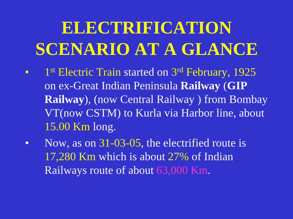
• 1st Electric Train started on 3rd February, 1925
on ex-Great Indian Peninsula Railway (GIP
Railway), (now Central Railway ) from Bombay
VT(now CSTM) to Kurla via Harbor line, about
15.00 Km long.
• Now, as on 31-03-05, the electrified route is
17,280 Km which is about 27% of Indian
Railways route of about 63,000 Km.

ELECTRIFICATION
SCENARIO AT A GLANCE
• Passenger Traffic carried out on Electrified
route is about 50%.
• Goods Traffic carried out on Electrified
route is 67%.

TRACTION VOLTAGE
SYSTEM
• Electric Traction introduced in Mumbai area on
1500 volt DC traction in 1925.
• 25 KV AC Traction introduced in 1960 which is
now universally adopted in Indian Railways.
• 1500 volt DC – 400 route Km.(which is also under
conversion to 25 KV AC).
• 25 KV AC, single phase 50 Hz – 16,880 route Km

Traction Distribution (TRD)
• Power Supply Installation (PSI)
• Overhead Equipment (OHE)
• Remote Control equipment
– RCC [Remote Control Center]
– SCADA- [Supervisory Control and Data
Acquisition system]


SCHEMATIC DIAGRAM OF TRACTION SUB STATION
Traction Sub
Station
R,Y
R,Y
(220/132/110 Kv)
LOCO
RAIL
OHE
25 KV AC
Single phase

TSS 1 TSS 2
Neutral section
(SP)
(SSPs)
(SSPs)-SubSectioning Post
Sub-Sector
Sector
SCHEMATIC DIAGRAM
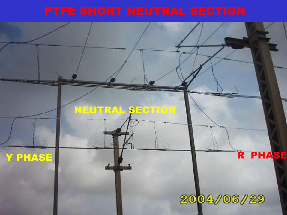
PTFE SHORT NEUTRAL SECTION
R PHASE Y PHASE
NEUTRAL SECTION

Neutral Section
A short section of insulated dead over-
head equipment which separates the
sectors fed by two adjacent substations
which are normally connected to different
phases.
• Warning Boards for Driver

OHE Arrangement
Mast
Mast
Catenary Wire
Contact Wire
Dropper
Automatic
Tensioning
Device
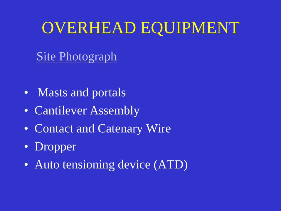
OVERHEAD EQUIPMENT
Site Photograph
• Masts and portals
• Cantilever Assembly
• Contact and Catenary Wire
• Dropper
• Auto tensioning device (ATD)

CANTILEVER ASSEMBLY
Sketch
Main parts
– Stay tube
– Bracket tube
– Steady arm
– Bracket Insulator
– Stay arm Insulator
– Register arm
– Suspension clamp

DROPPERS & BONDS
• DROPPERS
– A fitting used in overhead equipment
construction for supporting contact wire from
catenary
• BONDS
– An electrical connection across a joint in or
between adjacent lengths of rail
(structure bond, continuity bond, cross bond etc.)

Auto Tensioning Device (ATD)
• Auto tensioning device
– A device for maintaining the tension of OHE
conductors constant under all ambient
temperature conditions.
– Such OHE is called regulated OHE.

CONTACT & CATENARY
WIRE • Contact wire –
– cross sectional area - 107 sq.mm.
– diameter - 12.24 mm
– normal tension – 1000 kg
– breaking load – 3905 kg
• Catenary wire –
– cross sectional area - 65 sq.mm.
– diameter – 10.50 mm
– Normal tension – 1000 kg
– breaking load – 3920 kg

Electrical Clearance
• The minimum distance in air between live
equipment and the nearest earthed part.
• Vertical
i) long durations 320 mm
ii) short durations 270 mm
• Lateral
i) long duration 320 mm
ii) short duration 220 mm

Working Clearance
• Minimum clearance between live conductor/equipments and such earthed structure/live parts of different elementary sections where men are required to work shall be 2 m.
• Where the clearance is not obtained the structure shall be protected by earthed metallic screens or prescribed warning boards.
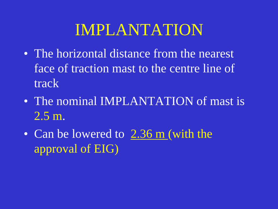
IMPLANTATION
• The horizontal distance from the nearest
face of traction mast to the centre line of
track
• The nominal IMPLANTATION of mast is
2.5 m.
• Can be lowered to 2.36 m (with the
approval of EIG)
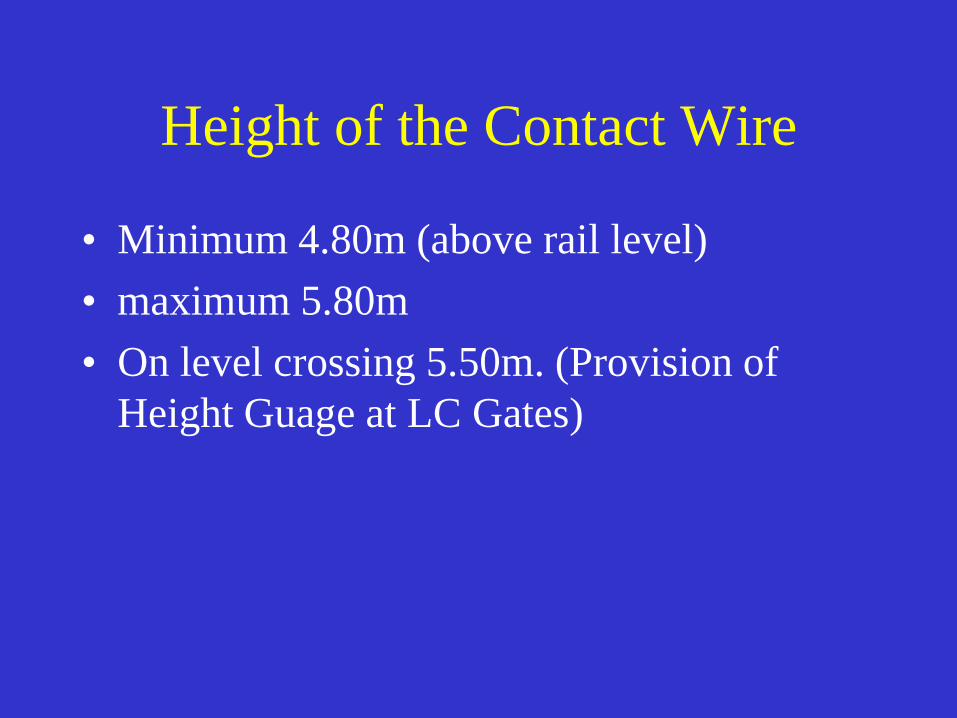
Height of the Contact Wire
• Minimum 4.80m (above rail level)
• maximum 5.80m
• On level crossing 5.50m. (Provision of
Height Guage at LC Gates)

OHE Inspection Car (Tower
Wagon)
• Used for maintenance of OHE and for attending to
break downs.
• Carries necessary tools for maintenance and break
downs such as tackles, straining screws, clamps,
ropes, ladders, adequate stock of insulators, length of
contact and catenary wires and other OHE fittings.
• Types of Tower wagon –
– Four Wheeler (speed potential upto 75 KMPH)
– Eight Wheeler (speed potential upto 110 KMPH)

• Pollution causes large number of insulator – flash over.
• Pollutants provide creepage path resulting into flash over of insulators and consequent creeping of circuit brakers.
• Types of pollution
– Saline pollution – caused by salt deposits in coastal areas.
– Chemical and industrial pollution - caused by waste from industries like hydrochloric acid, Sulphuric acid, particles of urea, cement etc.
Environmental Effect on OHE

Maintenance Schedules for OHE • Foot Patrolling – For visual inspection of every part of
OHE.
• Trolley Inspection – To observe closely the OHE
during day time.
• Current Collection Tests – To detect points at which
contact between the contact wire and pentograph is
unsatisfactory resulting in sparking. These tests are
performed at night.
• Special Checks – More frequent attentions on items
such as Insulators , section insulators, Isolating
switches, earth connections, Bird nest etc.

Maintenance Schedules for OHE –
contd.
• Annual Maintenance and OHE Inspection Car
Check – Replacement of defective fittings,
checking and correction of clearances, heights,
staggers, Checking of Masts, portels, contact wire
and catenary wire, insulators, neutral sections,
regulating equipments, clamps etc.
• Periodical Overhaul – At the interval of four
years.
• Re-tensioning of Unregulated OHE – At every six
months.

Power Supply Installations
• Traction Substation ( TSS)
• Switching Stations
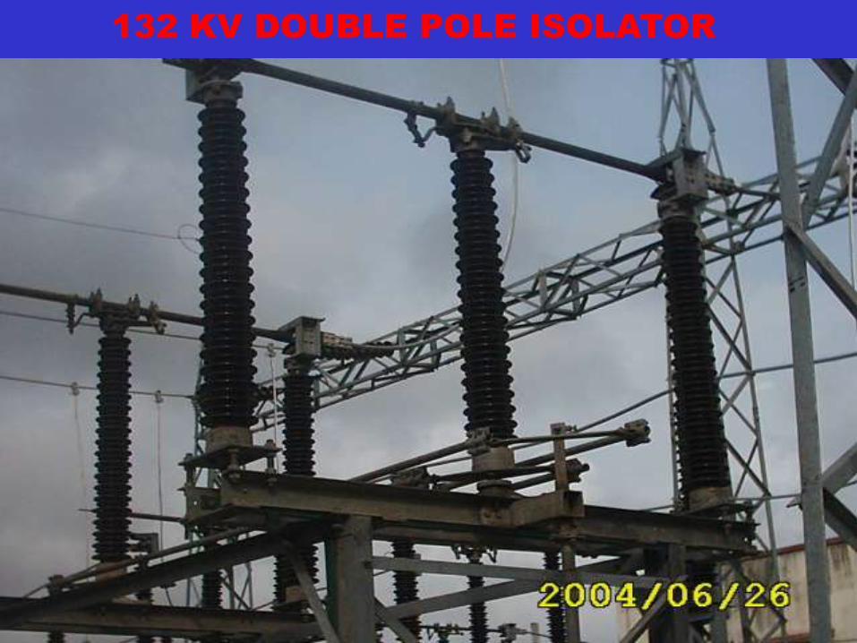
132 KV DOUBLE POLE ISOLATOR
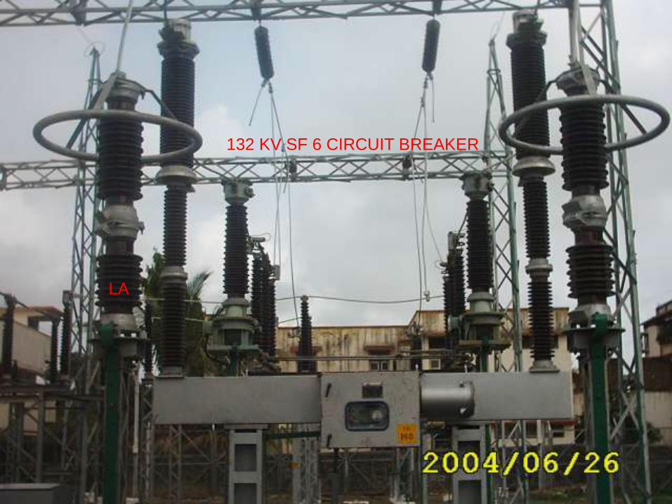
132 KV SF 6 CIRCUIT BREAKER
LA
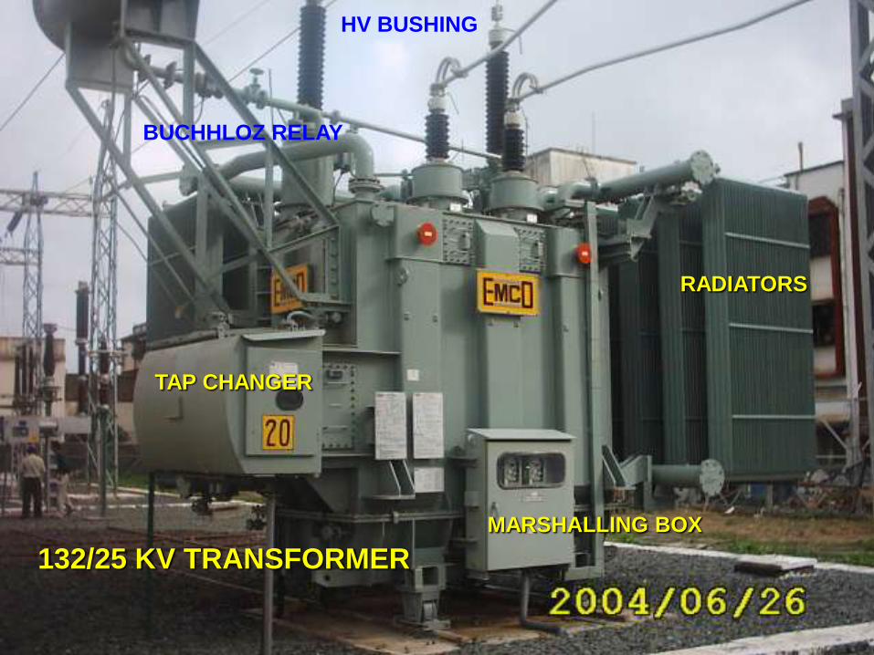
132/25 KV TRANSFORMER
HV BUSHING
RADIATORS
MARSHALLING BOX
TAP CHANGER
BUCHHLOZ RELAY

CURRENT
TRANSFORMER

25 KV SINGLE POLE ISOLATOR
MOVING ROAD FIX JAW
PEDASTAL INSULATOR
ARCING HORN
TIE-ROD INSULATOR

SUB SECTIONONG AND PARRALING POST
DC SECTION
CT
PT
CB
LA
BUS BAR

Maintenance Schedules of
Tractions sub-stations • Fortnightly maintenance -
– Going around the whole area of sub stations,
– inspect for general cleanliness, proper drainage, road and rail axis.
– Checking of batteries.
• Monthly maintenance –
– Bonding and earthing
– Oil level in transformers, circuit breakers etc.
– Insulators
– Traction transformer
– Operating mechanism of circuit breakers and interrupters.

Maintenance Schedules of
Tractions sub-stations-- Contd
• Quarterly maintenance
– Inspection of batteries and battery charges.
– PTs and CTs.
– Auxillary transformers.
• Half yearly maintenance
– Traction transformers – Testing of oil sample for
accidity and BDV.
– Control and Relay panel
– Traction transformers.
Maintenance Schedules of
Tractions sub-stations-- Contd
• Yearly maintenance
– Inspection of fence all around the sub station and
bonding between metal fencing panels and to earth.
– Lighting arresters.
– Bonding and Earthing
– Traction transformers.
– Control and Relay panel
– Batteries and battery charges.

THANK YOU

ELECTRIC LOCOMOTIVES
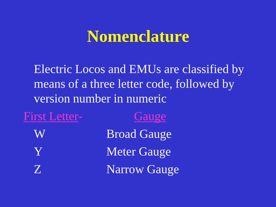
Nomenclature
Electric Locos and EMUs are classified by
means of a three letter code, followed by
version number in numeric
First Letter- Gauge
W Broad Gauge
Y Meter Gauge
Z Narrow Gauge

Nomenclature
Second Letter- Type of Traction (current)
C Continuous Current (DC)
A Alternating Current
CA Dual Current AC/DC
(D Diesel)
Third Letter – Type of Service
M Mixed Service P Passenger Service
G Goods Service S Shunting
U Multiple Units

Examples of Nomenclature
• WAP 4
– BG, AC, Passenger service,Version 4
• WCAM1
– BG, Dual Current, Mixed service, Version 1
• YCS 1
– Meter Gauge, DC, Shunting service, Version 1
• WCG 5
– BG, DC, Goods service,Version 5

Bogie Arrangements
• B ---Two axle bogie with one Traction Motor for both the axles.
• BO--- Two axle bogie with one Traction Motor for each axle.
• CO--- Three axle bogie with one Traction Motor for each axle.
• B-B Loco with two 'B' bogies
• CO-CO Loco with two 'CO' bogies

Types of Electric Locos
AC Locos
• B-B WAG1, WAG2, -WAG3, WAG4,
• BO - BO WAM1, WAM2, WAM3,
• CO-CO WAM4, WCAM1, WAP1, WAG5,
WAG6,WAG7,WAP3,WAP4, WAG9
DC Locos
• CO-CO WCM1, WCM2, WCM3, WCM4,
WCM5, WCG2

Comparison Of Pass & Goods
Loco for Passenger Loco for Goods
Less Tractive Effort More Tractive Effort
More speed Less speed
Lower gear ratio Higher gear ratio
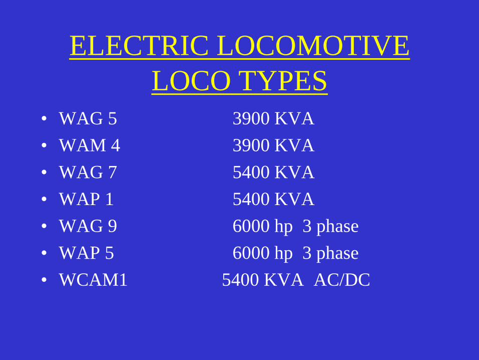
ELECTRIC LOCOMOTIVE
LOCO TYPES
• WAG 5 3900 KVA
• WAM 4 3900 KVA
• WAG 7 5400 KVA
• WAP 1 5400 KVA
• WAG 9 6000 hp 3 phase
• WAP 5 6000 hp 3 phase
• WCAM1 5400 KVA AC/DC

CIRCUIT DIAGRAM OF LOCO
A TYPICAL CIRCUIT DIAGRAM OF CONVENTIONAL ELECTRIC LOCOMOTIVE IS SHOWN HEREWITH

Main Equipments of Electric
Locomotive
• Roof Equipments –
– Pantograph – for current collection
– Circuit Breaker – for making on/off electric supply from panto to power equipments
• On Board power equipments
– Traction Transformer – for stepping down voltage from 25 KV to 750/1500 volts.
– Rectifier – for converting 750 AC to 750 volt DC for feeding supply to traction motors.
– Arno Converter – for converting single phase 750 volt AC to 3 phase 415 volt for feeding supply to auxiliary machines like compressor/exhausters.

Main Equipments of Electric
Locomotive • Under slung Equipments –
– Traction motor – for producing tractive effort required to move train.
– Suspension arrangement – system for transmitting tractive effort from traction motor to bogie.
– Brake System – for braking of electric loco and train
– Batteries – for feeding supplies to control system
-baby compressor for initial raising of pantograph.

Specific Energy Consumption
(SEC)
• SEC for Goods Train= 10 Kwh per 1000
GTKM
• SEC for Passenger Train= 19 Kwh per
1000 GTKM

• About Rs. 20 lacs per loco per year
MAINTENANCE COST OF
LOCOS

THANK YOU