Topic Communication systems used in seismology 1 Introduction
20
Information Sheet IS 8.2 1 Topic Communication systems used in seismology Authors Michael Guenther GFZ German Research Centre for Geosciences, Department Geoengineering Centres, Section Centre for Early Warning, Telegrafenberg, D-14473 Potsdam, Germany; E-mail: [email protected] Angelo Strollo GFZ German Research Centre for Geosciences, Department 2 Physics of the Earth, Section 2.4 Seismology, Telegrafenberg, D-14473 Potsdam, Germany E-mail: [email protected] Version August 2013; DOI: 10.2312/GFZ.NMSOP-2_IS_8.2 Page 1 Introduction 1 2 Requirements analysis 2 3 Design of a communication system for a seismic network 4 4 Overview of current communication technologies 6 4.1 Wired communication technologies 6 4.2 Wireless communication technologies 8 4.3 Satellite communication technologies 10 5 Conclusions 12 Acknowledgment and comments 14 References 14 Appendix 1: Case study of a communication infrastructure for a seismic network of 25 stations for tsunami early warning in the Indian Ocean 15 Appendix 2: List of manufacturers and products 20 1 Introduction With the rapid development of communication technology, especially in the area of satellite communication, new possibilities arise for the design and implementation of seismic networks. A decade ago, the only financially appropriate solution to integrate seismic stations into a network was often the use of terrestrial wireless links, such as radio frequency telemetry systems. These systems, although good value for money, are usually limited by their maximum link distance and their data throughput. As prices for satellite-based communication services have dropped drastically, these services have become a widely used alternative for largely distributed seismic networks. This Information Sheet provides a short overview of a range of communication systems useful in remote areas where regular Internet access or dial-up phone lines are not available.
Transcript of Topic Communication systems used in seismology 1 Introduction

Information Sheet IS 8.2
1
Topic C o m m u n i c a t i o n s y s t e m s u s e d i n s e i s m o l o g y Authors Michael Guenther GFZ German Research Centre for Geosciences,
Department Geoengineering Centres, Section Centre for Early Warning, Telegrafenberg, D-14473 Potsdam, Germany; E-mail: [email protected] Angelo Strollo GFZ German Research Centre for Geosciences, Department 2 Physics of the Earth, Section 2.4 Seismology, Telegrafenberg, D-14473 Potsdam, Germany E-mail: [email protected]
Version August 2013; DOI: 10.2312/GFZ.NMSOP-2_IS_8.2
Page 1 Introduction 1 2 Requirements analysis 2 3 Design of a communication system for a seismic network 4 4 Overview of current communication technologies 6
4.1 Wired communication technologies 6 4.2 Wireless communication technologies 8 4.3 Satellite communication technologies 10
5 Conclusions 12 Acknowledgment and comments 14 References 14 Appendix 1: Case study of a communication infrastructure for a seismic network of 25 stations for tsunami early warning in the Indian Ocean 15 Appendix 2: List of manufacturers and products 20 1 Introduction With the rapid development of communication technology, especially in the area of satellite communication, new possibilities arise for the design and implementation of seismic networks. A decade ago, the only financially appropriate solution to integrate seismic stations into a network was often the use of terrestrial wireless links, such as radio frequency telemetry systems. These systems, although good value for money, are usually limited by their maximum link distance and their data throughput. As prices for satellite-based communication services have dropped drastically, these services have become a widely used alternative for largely distributed seismic networks. This Information Sheet provides a short overview of a range of communication systems useful in remote areas where regular Internet access or dial-up phone lines are not available.

Information Sheet IS 8.2
2
Some turnkey solutions for seismic networks are commercially available and most already integrate a communication system (e.g. Libra VSAT provided by Nanometrics) to avoid extensive analysis and design work by the customer. This has advantages and disadvantages (see 8.8.4). The communication system is well optimized for seismic data transmission for the manufacturers turnkey solution, but usually lacks flexibility. This Information Sheet aims to support the requirements analysis, the design phase and the selection process when upgrades of existing seismic networks or new installations are planned without using a turnkey solution. Communication technologies and their relevant characteristics are briefly compared with emphasis on practical aspects. Finally, Appendix 1 provides a quick network design schema using the information provided in this sheet and Appendix 2 a list of manufacturers and products the reader may refer to for further information. 2 Requirements analysis Generally the selection process is a trade-off between requirements driven by the application of the seismic data, characteristics of available communication systems and most importantly financial constraints of the project. Cost aspects are usually in focus; however, it is of very high importance to thoroughly understand the requirements of the application for the seismic network before making a good choice. When designing a seismic network the relevant points to be considered with respect to the communication system are the following:
• Are seismic data needed in near real-time or downloaded at defined intervals? o Type of communication link needed (permanent online and streaming or dial-
up and file-based transmission) • Is the network a temporary or permanent deployment?
o Equipment transportation and installation efforts/ costs • What are the requirements regarding resolution and sampling rate of the waveforms?
o Data rate limits and operational costs • How wide is the geographical distribution of the stations?
o Link distance limits and coverage area • How remote are the stations?
o Communication systems availability at site o Travel and transportation costs o Power supply investments for communication system o Back-up communication system for troubleshooting
• What are the availability constraints of the network (especially during natural disasters)?
o Shared vs. dedicated links o Terrestrial vs. satellite based systems o Back-up communication system
• Are there data security requirements? o Encryption and authentication support
• Last but not least: what is the project budget? o Hardware costs o Operational costs o Transportation costs

Information Sheet IS 8.2
3
o Power supply investments o Travel and maintenance costs
Nowadays, with the increasing demand for high-quality seismic data for both, pure scientific detailed studies as well as early warning and rapid response networks, the communication system is becoming a key feature of a seismic station. In particular, different applications in seismology will impose different requirements on the communication infrastructure. A simplified list of the main seismological applications and their peculiarities, with respect to the points listed in the previous paragraph, is:
1. Early warning systems – permanently installed with real-time data delivery to send out timely warnings to the population as a national service (e.g. for earthquakes, tsunami, volcanic eruptions, landslides, etc.). The stations are generally located in very remote areas. Latency of the communication system technology may become an issue for on-site early warning (50 km leads to approximately 6 seconds time between the first P phase and the following destructive S phase). For other natural hazards, generally the warning time is not so short and latency of the communication technique used is not an issue.
2. Rapid response, earthquake monitoring networks – the aim of this network type is to have quick parameterization of an earthquake (location, magnitude, shake map) and fast earthquake parameters dissemination. Generally the earthquake information should be disseminated within few minutes from the origin time. Depending on the dimension of the target seismogenic area (local, regional or global), the size of the network and the dissemination time frame may vary.
3. Emergency deployments – after disastrous events, seismologists generally increase the number of stations with dense temporary deployments near the epicentre to have a better characterization of the rupture that generated the earthquake, as well as to investigate site effects. In the past, this task was generally done offline. Nowadays, with better integration among rescue teams and seismologists dedicated to emergency deployments, the real-time communication may be useful to follow the aftershock sequence evolution and even predict its evolution. Moreover, real-time state of health monitoring of buildings may be done especially for critical infrastructures (i.e. hospitals, bridges, tunnels, pipelines, etc.)
4. Building monitoring – besides the state of health monitoring done in emergency deployments, in some countries exposed to a high earthquake hazard, it is becoming a standard practice to continuously monitor the state of health of critical infrastructures in real-time and follow its state of health during large earthquakes. Moreover, engineers also perform offline data acquisition on buildings in order to better understand their behaviour.
5. Seismic arrays and micro-arrays – these are generally small seismic networks installed to have a detailed investigation of small scale phenomena. They may be used to investigate small earthquake swarms, induced seismicity, seismic noise, etc. In general, they do not require continuous real-time links, but for some applications (expected induced seismicity) the network operator may demand the real-time acquisition and processing.

Information Sheet IS 8.2
4
Table 1 provides a schematic overview of the main seismological applications discussed above with respect to their communication systems requirements. Table 1 Comparative matrix for applications based on seismic networks. Please note that for large events, the rupture area may go beyond the indicated geographic spread of the network.
3 Design of a communication system for a seismic network All applications discussed in the previous paragraph have one thing in common: there is a central storage facility to collect and process the data of all stations. This facility is usually located at a data centre or is simply a central computer installed remotely in the field. It is important to be clear about the data flow of the network in order to select a suitable topology to accommodate the general requirements. Each network topology has advantages and disadvantages (Table 2). These should be mapped against the requirements of the seismological application in order to optimize data flows. Often a combination of different topologies provides the optimal result, but hybrid topologies are more complex to troubleshoot and maintain. This can lead to higher maintenance costs. To design the network, a topology map should be drafted, indicating link distance and, if not uniform, the amount of data transmitted on each link. The data rate estimation must consider the number of sensors and components at each station, applied sampling rates, and resolution of the digitizer. Data acquisition protocols, such as SeedLink, may improve the efficiency in data transmission, depending on the compression algorithm used. (see 8.6.6). The draft should also indicate if the link needs to be available permanently or if a dial-up link is sufficient. In addition to the inter-station network, each single station also has an internal- or intra-station network to connect digitizers with other local hardware (i.e., a local computer as data-buffer), as well as to the communication gateway on site (Figure 1). The gateway is the element of the
Application Type
Scale Geographic Spread
Sampling/ Data Rates
Link Type Required Robustness
Remoteness of Stations
Early Warning Local <100 km High for local and low for global scale
Continuous link for real-time data streams
Very high Remote Regional <1000 km Global Global
Rapid Response
Local <100 km High for local and low for global scale
Continuous link for real-time data streams
High Remote Regional <1000 km Global Global
Emergency Deployments
Local <500 km Very high/High Offline, dial-up or real-time streaming
High if real-time
Depend on EQ location (in general urban areas)
Building Monitoring
Local <10 km Very high Offline, dial-up or real-time streaming
High if real-time
Urban areas
Seismic Arrays and Micro-Arrays
Local ~100 km Very high/high Offline or real-time streaming
Low Depend on the target area
Information Sheet IS 8.2
5
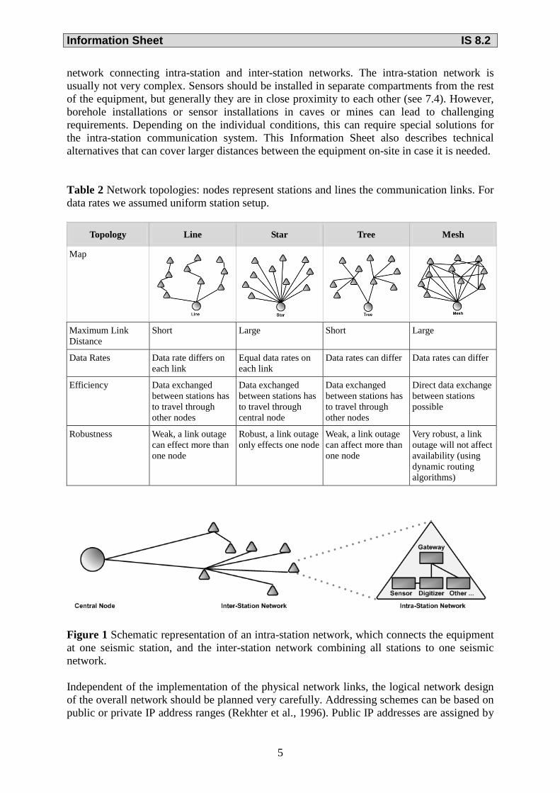
network connecting intra-station and inter-station networks. The intra-station network is usually not very complex. Sensors should be installed in separate compartments from the rest of the equipment, but generally they are in close proximity to each other (see 7.4). However, borehole installations or sensor installations in caves or mines can lead to challenging requirements. Depending on the individual conditions, this can require special solutions for the intra-station communication system. This Information Sheet also describes technical alternatives that can cover larger distances between the equipment on-site in case it is needed. Table 2 Network topologies: nodes represent stations and lines the communication links. For data rates we assumed uniform station setup.
Figure 1 Schematic representation of an intra-station network, which connects the equipment at one seismic station, and the inter-station network combining all stations to one seismic network. Independent of the implementation of the physical network links, the logical network design of the overall network should be planned very carefully. Addressing schemes can be based on public or private IP address ranges (Rekhter et al., 1996). Public IP addresses are assigned by
Topology Line Star Tree Mesh
Map
Maximum Link Distance
Short Large Short Large
Data Rates Data rate differs on each link
Equal data rates on each link
Data rates can differ Data rates can differ
Efficiency Data exchanged between stations has to travel through other nodes
Data exchanged between stations has to travel through central node
Data exchanged between stations has to travel through other nodes
Direct data exchange between stations possible
Robustness Weak, a link outage can effect more than one node
Robust, a link outage only effects one node
Weak, a link outage can affect more than one node
Very robust, a link outage will not affect availability (using dynamic routing algorithms)

Information Sheet IS 8.2
6
the Internet Corporation for Assigned Names and Numbers (ICANN, http://www.icann.org/) and are guaranteed to be globally unique to enable routing of data packets via the Internet. Usually public IP ranges are rented from Internet service providers (ISP), which implies an additional monthly service charge. If stations do not need Internet access and data is exchanged with the central node only, the use of private IP ranges can reduce operational costs and increase security, as well as reliability. In a common scenario, each station runs its own private IP network providing addresses for the equipment installed on site. The intra-station networks are then combined into a larger IP network that can be easily routed at the data centre. Therefore IP addressing schemes should be discussed and designed in close cooperation with the IT- or network department of the institution that hosts the central node before the installation campaign starts. It will be difficult to remotly change intra-station IP configurations again after the network installation has been completed. Another aspect to consider is that sensor networks usually change and grow over time, be it with additional equipment added at stations or additional stations added to the network. The developed IP schema should also address this and ensure the scalability of the system. 4 Overview of current communication technologies 4.1 Wired communication technologies Wired solutions are usually cheap, robust, and provide sufficient throughput capabilities to transport seismic data. However, they have strong limitations regarding the distance to be covered (cable laying effort). Generally, they only provide a good solution for the intra-station network connecting the components on site. Most seismological instruments are already equipped with communication interfaces, such as Ethernet cards or serial ports. The following list also indicates serial and Ethernet based solutions, if the distance at a station exceeds the standard limits of these technologies. The industry standard ANSI EIA defines different specifications of communication links based on serial ports. EIA-232 or RS-232 (Texas Instruments, RS-232, http://www.datasheetarchive.com/ANSI%2FTIA%2FEIA-232-F-datasheet.html) is the classic serial connection. It provides data rates up to 19200 Baud using a null modem cable with a maximum length of 15 m. Longer transmission lines can be used but will decrease the data rate (e.g., 300 m, 4800 Baud). Equipment ,such as computers, digitizers, or communication terminals often provide integrated RS-232 interfaces already (Figure 2). Configuration of the link is straight forward and easy by configuring baud rate, data bits, parity, stop bits, and flow control on both sides of the link.
Figure 2 Example of a serial connector and a serial PCI card.

Information Sheet IS 8.2
7
If distances or data rate requirements are too high to use RS-232, another option is the use of EIA-485 (RS-485) cards (Texas Instruments, RS-485, http://www.datasheetarchive.com/TIA-485-A-datasheet.html). This specification provides a cable length of 1200 m and 12 Mbit/s throughput, however, this maximum transfer rate is achieved only with cable lengths up to 15 m. If RS-232 interfaces are already integrated into the equipment and only the distance to be covered is too large, RS-232 to RS-485 adaptors provide a valuable alternative (Figure 3). However, this will not increase the data rate provided by RS-232.
Figure 3 Example of an RS-232 to RS-485 adaptor.
The Institute of Electrical and Electronic Engineers (IEEE) developed the standard IEEE 802.3, which defines different specifications of Ethernet based communication links (IEEE Standards Association, 802.3, http://standards.ieee.org/about/get/802/802.3.html). The most commonly used specification nowadays is Fast Ethernet (100Base-T) providing up to 100 Mbit/s transmission rate over shielded or unshielded twisted pair copper cable (STP/UTP). Equipment to be connected needs a network interface card (NIC), which is often already integrated (Figure 4). An Ethernet switch then connects the different devices into one local network. The maximum cable length (segment size) on 100Base-T should not exceed 100 m between two devices. For the installation of the RJ45 connectors a crimping tool is needed. Link configuration is easy by configuring IP number, netmask, and gateway IP.
Figure 4 Example of an RJ45 connector and a PCI based network interface card.
A 100Base-FX PCI card can be added to the equipment if a PCI slot is available. If the equipment already has integrated 100Base-T interfaces, an external 100Base-FX transceiver can be used to convert from 100Base-T to 100Base-FX (Figure 5). 100Base-FX supports a 100 Mbit/s transmission rate over fiber optic cables with a maximum cable length of 2000 m. In addition to supporting longer distances, fiber optic cables are immune to electrical hazards, such as lightning strikes and ground currents that may occur. The fiber optic connectors are commonly known as "SC" connectors. Only qualified personnel may install these connectors and a range of special tools are needed (Fiber Stripper, Cleaver, Wipes, Kevlar Scissors). It is also possible to purchase pre-fabricated cables and take them to the site.
Figure 5 Example of an external 100Base-FX transceiver and SC-connectors.

Information Sheet IS 8.2
8
Another possibility to extend FastEthernet beyond the normal IEEE 802.3 limitation of 100 m is the use of a pair of VDSL Ethernet Extenders (Figure 6). With increasing cable length, data rates will decrease from the 100 Mbit/s provided by 100Base-T, but cables between the terminals can be extended up to some kilometers by using normal STP, UTP or even common RJ11 telephone cable. A cable length of 8000 m will limit the data rate to 128 kbit/s.
Figure 6 Example of a VDSL Ethernet Extender.
4.2 Wireless communication technologies Wireless solutions are usually cheap and easy to install. They can be used to link longer distances, more than 1000 m. They provide sufficient throughput capabilities to transport seismic data. However, they are relatively sensitive to obstacles in the wave propagation path and to changing atmospheric conditions that can attenuate the signal. A clear "line of sight" between transmitter and receiver is enough for a robust connection for very short links only. Longer distances are very prone to RF signal attenuation based on rain fade and Fresnel zone obstruction. They require a proper link budget calculation to ensure stability (see 7.3.3 and 8.9.3). Wireless modems/ routers have the disadvantage of increased power consumption compared to wired solutions. Systems usually consume between 5-10 W on each side of the link, which impose additional demands on the power system at the station. The WLAN standards IEEE 802.11g (2.4 GHz) and IEEE 802.11a (5 GHz) support data transmission over a wireless terrestrial link (IEEE Standards Association, 802.11, http://standards.ieee.org/about/get/802/802.11.html). Due to its widespread use, the cost of 2.4 GHz equipment is generally lower, but the frequency band is also used by other wireless communication technologies, such as Bluetooth and microwave systems, which can lead to harmful interference in populated areas. Running a wireless LAN link involves no operational costs as frequencies can be used freely. WLAN can cover distances from 50 to 500 m using omnidirectional antennas. Using directional antennas, the coverage can be extended to several km (Figure 7). The performance of some devices, especially in combination with directional antennas and a free Fresnel zone, allows connections over very long distances. In tests, links over up to 70 km have been achieved by the use of directional antennas. The maximum allowed radiated power of WLAN systems (calculated from transmission power and antenna gain) is usually limited by national regulations and must not be exceeded.
Figure 7 Examples of omnidirectional and directional antennas and a WLAN modem.

Information Sheet IS 8.2
9
The data transfer rate on both specifications, 802.11a and 802.11g, is 54 Mbit/s, although these rates are seldom achieved in practice. With the latest specification 802.11n maximum data rates can be increased up to 600 Mbit/s by expanding the channel width from 20 MHz to 40 MHz and establishing several physical input and output channels using multiple separate antennas. Generally, an increase in link distance will decrease the maximum data rate provided by the system. Especially for long range links, the installation can become quite complex with very high mast poles and difficult alignment procedures. Link distances can also be doubled with the use of “repeater stations”. A number of commercial products support data transmission over radio frequency (RF) telemetry links. The systems mainly differ in transmission rates, operating frequencies (VHF 160-200 MHz and UHF at 450 MHz and 900 MHz) and modulation techniques. Running the system involves no operational costs as the frequencies can be used freely, however, some frequency bands need operating permissions by national agencies. Bidirectional broadband systems can provide transmission rates of 150 kbit/s. Some systems specialize on link distance and provide up to 150 km coverage without repeaters (Figure 8). With increasing link distance, the transmission rate decreases for a given transmitter power. Especially for long range links, the installation can become complex with very high mast poles and difficult alignment. Link distances can be doubled with the use of “repeater stations”. Compared to WLAN links, RF links are more robust against rain attenuation due to the lower frequencies used. However, terminals are generally more expensive.
Figure 8 Example of an RF telemetry modem and a Yagi antenna.
If available, it is also possible to use the public mobile phone network for data transmission. Packet oriented standards extending the Global System for Mobile Communications (GSM), such as GPRS, UMTS and LTE support both transmission of voice and transfer of data. Some available wireless modems have built-in ability to connect to all three services (Figure 9). Cell availability is depending on the provider and usually limited to inhabited areas. Provided data rates differ depending on the standard
Figure 9 Example of a mobile phone antenna and modem supporting all standards: GPRS, UMTS and TLE.

Information Sheet IS 8.2
10
used (GPRS 53.6 kbit/s; 384 kbit/s; LTE 100 Mbit/s) but also on saturation of the shared infrastructure. Especially during and after catastrophic events, such as earthquakes, congestion or complete system blackouts are common. Configuration and installation of the modem is straight forward and easy. No antenna alignment is required. 4.3 Satellite communication technologies At some remote stations satellite-based systems are the only alternative for seismic data transmission due to their availability at even very remote locations. Due to their independence from terrestrial infrastructure, they are very robust against failure during natural disasters. However, satellite capacities are generally shared with other companies/ services. Link saturation problems, which may occurr, can be overcome by configuring bandwidth allocation methods such as committed information rates (VSAT) or constant bit rate modes (BGAN, Thuraya). Therefore, these systems provide a robust solution for early warning systems that require very high availability even during exceptional circumstances. VSAT terminals represent the current state of the art measure for permanently installed seismic stations. Depending on their location, a suitable satellite (footprint, see Figure 10) and teleport operator must be selected. In principle, VSATs can be used worldwide, with the exception of the polar regions (latitudes larger than 70 degrees). Links can provide data rates up to several Mbit/s. Depending on data rate requirements of the station or the entire network, suitable bandwidth must be allocated. VSAT systems generally work on Ku-band, C-band, and Ka-band frequencies. C-band systems (smaller rain attenuation, larger antennas) are more common in Southeast Asia, Central and Southern Africa and Latin America, while Ku- and Ka-band systems (smaller antennas, but susceptible to rain attenuation) are more common in Europe, North Africa, Central Asia and North America. The influence of rain attenuation can also be mitigated by the use of adaptive coding and modulation techniques, e. g., utilized in DVB-S2. The required equipment consists of an indoor unit (modem) and an outdoor unit (Figure 11). The outdoor unit (antenna, transmitter, and receiver) must be chosen depending on the calculated link budget. Transportation of antennas can cause problems, as typical sizes for Ku and Ka-band range between 75 cm and 1.8 m and C-band between 1.8 m and 2.4 m.
Figure 10 Example satellite footprint of Eutelsat 21B (source: www.eutelsat.com).
Figure 11 Example of a VSAT modem (indoor unit) and parabolic antenna with receive and transmit unit (outdoor unit).

Information Sheet IS 8.2
11
Another great disadvantage of a VSAT system is the high power consumption. Modems usually require around 25 W and additional 5-10 W per Watt of transmit unit power (BUC), which adds up to an overall consumption of approximately 35-70 W. Complex tests (cross-polarization and 1 dB compression test) must be performed, together with the satellite or teleport provider, during installation in order to activate the link. Compared to other satellite communication systems, the operational costs are low (see Table 3). The Inmarsat BGAN satellite communication system uses three geostationary satellites, which provide global coverage up to 70 degrees latitude. The system does not cover the polar regions (Figure 12). It allows the transmission of data with a maximum upload rate of 240 kbit/s. Data volume-based tariffs (usually cheaper) or time-based tariffs (for real-time transfers) can be selected. Compared to VSAT, the transfer costs are very high in both modes. The system should be deactivated for times when no data transfer is taking place. There are BGAN terminals of different manufacturers on the market. All of the devices are very compact, comparable to the size of a laptop, weighing less than 3 kg and have relatively low power consumption (less than 25 W). Modem and antenna are usually combined in one piece of transportable outdoor equipment (Figure 13). During installation, the terminal antenna must be roughly aligned to one of the three BGAN satellites (5 degrees accuracy sufficient). No complicated activation tests are required, however the SIM card must be commissioned/ activated by the BGAN provider before it can lock to the network.
Figure 12 BGAN coverage map (source: www.inmarsat.com).
Figure 13 Example BGAN modem with integrated antenna.
Thuraya provides a satellite telephone service based on two geostationary satellites covering Europe, Australia, the Middle East, Africa, Central and Southeast Asia (Figure 14). It sells two data transmission terminals: Thuraya IP and Thuraya IP Plus. Both terminals can be used in two data transmission modes: “Standard IP” has a variable bit rate and offers up to 444 kbit/s data connectivity on a shared mode or best effort basis. “Streaming IP”, also known as Constant Bit Rate offers dedicated data connectivity ranging from 16 kbit/s to 384 kbit/s.
Figure 14 Thuraya coverage map (source: www.thuraya.com).

Information Sheet IS 8.2
12
Modem and antenna are integrated in one piece of equipment weighing less than 2 kg (Figure 15). Power consumption of both terminals is less than 25 W while transmitting. Prices for terminals and transmission are comparable to Inmarsats BGAN system.
Figure 15 Thuraya IP Plus modem with integrated antenna.
The Iridium satellite telephone system provides global coverage for all latitudes, including the poles. Since the 66 cross-linked low-Earth orbiting (LEO) satellites have polar orbits, the coverage above the poles is even particularly good (Figure 16). The antenna of the iridium terminal need not be aligned with a satellite, hence installation is very simple. Iridium offers different data services. The only broadband data transmission OpenPort provides data rates up to 128 kbit/s. The tariff plans of the OpenPort system are more complicated compared to BGAN, and transmission costs are generally higher. Both parts of the system (ADE (above decks equipment) – antenna and BDE (below decks equipment) – modem) are easy to install (Figure 17). No activation tests are required, however SIM cards must get commissioned/ activated by the provider. The power consumption in data transfer mode is less than 25 W. Launching in 2015, Iridium NEXT will substantially enhance and extend Iridium services, delivering higher data speeds (L-Band: 1.5 Mbit/s, Ka-band: 8 Mbit/s) (Iridium, Iridium Next, http://www.iridium.com/about/iridiumnext.aspx).
Figure 16 Iridium global coverage map (source: www.iridium.com).
Figure 17 Iridium antenna (ADE) and OpenPort terminal (BDE).
5 Conclusions All technologies discussed in the previous paragraph provide certain advantages and disadvantages, depending on the particular issues under consideration. It is important to quantify the differences and compare them to see if they really matter. Moreover, even there may be more than one suitable technology. It is obvious that choosing the right one can reduce the overall costs of the project. Intra-station networks can be implemented using wires, based on the provided interfaces integrated in the seismic equipment (serial or Ethernet). Using adaptors, distances can be

Information Sheet IS 8.2
13
easily extended up to several hundreds of meters, if needed. To avoid extensive cable laying work, wireless LANs can also be an alternative in unpopulated areas, where interferences are not expected. Table 3 Comparative matrix for communication systems used in seismic networks. For column Installation/ Activation, Easy/ Moderate/ Complex have been defined as follows: Easy - no expert knowledge required; Moderate - basic network knowledge sufficent; Complex specialist knowledge/or special tools needed. Numbers indicated in columns Hardware- and Operating Costs are estimations in $US and should only be used for relative comparison.
Type Distance/ Coverage
Data Rate Installation/ Activation
Hardware Costs
Operating Costs
Link Reliability
Power Consumption
Wire
d Co
mm
unic
atio
n
RS232 (Serial)
15 m (19200 Baud), 300 m (4800 Baud)
<20 kbit/s (depending on cable length)
Easy PCI Card <50 None Very robust <1 W
RS485 (Serial)
<1200 m <12 Mbit/s
Easy Adaptor <10 None Very robust <1W
100Base-T (FastEthernet)
<100 m <100 Mbit/s
Easy PCI Card <20 None Very robust <1 W
100Base-FX (Fibre Optics)
<2000 m <100 Mbit/s
Complex PCI card<150 Adaptor<300
None Very robust <1 W
VDSL Ethernet Extender
<8000 m <100 Mbit/s (depending on cable length)
Easy <200 per piece
None Very robust <5 W
Wire
less
terr
estr
ial
Com
mun
icat
ion
WLAN
<70 km 802.11a/g <54 Mbit/s 802.11n < 600 Mbit/s (depending on link distance)
Moderate, complex on long range links
Modem & antenna 50 – 500
None / private link
Good <10 W
RF Links
<150 km
<200 Kbit/s (depending on link distance)
Complex Modem & antenna 300 – 3000
None / private link
Good <10 W
Mobile phone network
Provider dependent
GPRS <53.6 Kbit/s UMTS <384 Kbit/s LTE <100 Mbit/s
Moderate Modem & antenna 100 – 1000
Low <0.05/MB
Bad, public shared link
<5 W
Wire
less
sat-
base
d Co
mm
unic
atio
n
VSAT
Global, depending on satellite footprint, excluding pole regions
<5 Mbit/s Complex and heavy equipment
Modem & antenna 1500-4000
Low <0.05/MB
Good, using committed information rate settings
>25 W
Inmarsat BGAN
Global, excluding pole regions
<240 kbit/s Moderate Modem & integrated antenna 2000-4000
High ~5,-/MB
Good, in constant bit rate mode
<25 W
Thuraya IP Plus Europe, Australia, Middle East, Africa, central- and southeast Asia
16 kbit/s to 384 kbit/s in streaming mode
Moderate Modem & integrated antenna ~3000
High ~5,-/MB
Good, in constant bit rate mode
<25 W
Iridium OpenPort
Global, including pole regions
<128 kbit/s Moderate Modem & antenna ~4000
Very high >5,-/MB
Good <25 W
Local inter-station networks can be set up using WLAN and directional antennas if stations are in less than 70 km range. Using RF links, distances can reach up to 150 km at most. Both systems are prone to interference with other wireless systems in urban areas and sound link budget calculations should be performed which require special knowledge and tools (e.g. a

Information Sheet IS 8.2
14
spectrum analyser). The system distance limitations can be extended by the use of repeater stations, but this will add complexity to the communication network and complicate troubleshooting and maintenance. In case mobile phone reception exists at the station and reliability during earthquakes is not of highest importance, mobile phone modems can be a low priced and very effective alternative. For regional and global networks, satellite based communication systems are available even in the remotest areas, but come with a large price tag. For applications requiring high availability during global/ regional disasters, it is reasonable to rely on space-based infrastructures. VSAT systems have lower operational costs, but are difficult to transport, install, and activate. The high power consumption of VSATs increases the installation costs further. However, for permanent streaming from seismic stations with sampling rates higher than 10 Hz, VSATs are currently the only financially feasible selection as operational costs of the satellite-based alternatives are very high. For temporary installations or very low sampling (data) rates Inmarsats BGAN or Thuraya are a good solution. These systems are easy to transport, install and activate. For the polar regions above the 70th latitude, Iridium provides the only satellite-based communication solution. These communication technologies may become a good alternative for permanent seismic networks in the future if prices will further decrease. Another way to allow the extensive usage of these technologies will be to complement existing seismic networks with stations running the pre-processing of waveform data on-site, if a computer is available. This would drastically reduce data transfer requirements of the inter-station network, because only a few parameters, such as picks, amplitudes, peack ground acceleration, velocity, etc. may be transmitted to the data centre and not the complete high sampling rate waveforms. Acknowledgments and comments We thank P. Bormann for additional editing of this Information Sheet. We are also grateful to the reviewers C. Milkereit and K. Wendlandt, which improved the text significantly. P.L. Evans and S. Gensch kindly amended our English. Identifying the name of the instruments’ manufacturers is not meant to be an endorsement of their products. Prices and costs mentioned in this Information Sheet can vary a lot in time and depending on regions/ countries. They cannot be used as absolute values but only for relative comparison. The list of manufacturers provided in Appendix 2 is a subjective selection and is by no means complete. References Rekhter, Y., Moskowitz, B., Karrenberg, D., de Groot, G., and E. Lear, Address Allocation for Private Internets, BCP 5, RFC 1918, February 1996. Angermann M., Guenther M., and Wendlandt K., Communication architecture of an early warning system. Nat. Hazards Earth Syst. Sci., 10, 2215–2228, 2010.

Information Sheet IS 8.2
15
Appendix 1 Example design of a communication infrastructure for a seismic network of 25 stations used for tsunami early warning in the Indian Ocean Step 1) Requirement Analysis Continuous seismic data streams are needed at the data centre to calculate earthquake parameters in real-time, identify if there is a tsunami potential and send out a timely warning to the population under threat.
• Stations must be constantly online, streaming data on permanent communication links to the data centre.
The network is permanently deployed and will continuously be enlarged.
• Operational and maintenance costs outweigh initial investments in equipment, training, transportation, installation and activation.
Each station hosts two types of sensors, a very broad band seismometer and an accelerometer, both having three components. Selected sampling frequencies are 50 Hz for the seismometer and 100 Hz for the accelerometer, both connected to a 24 bit digitizer.
• 3 components * 50 Hz * 24 bit + 3 components * 100 Hz * 24 bit = 10800 bit/s. The SeedLink protocol is used to transfer station data to the observatory. SeedLink uses Steim compression, which can almost halve the data quantity (see 8.6.6).
• The data to be transmitted using the communication system varies between 5-10 kbit/s per link depending on compression efficiency.
Figure 18 Geographical distribution of the stations and observatory location. The deployment area of the network is along the Sunda arc covering several thousand kilometres (Figure 18).
• Link distances between stations are generally over 500 km. Stations are in very remote areas and located in three different countries. To reach stations, long and expensive journeys are necessary with several connecting flights.

Information Sheet IS 8.2
16
• A secondary backup communication system would be useful to reduce maintenance costs.
High network availability is required, being specified as above 99 %. Data streaming must be ensured during and immediately after the occurrence of large earthquakes.
• Link robustness is of highest importance, higher than budget constraints. Table 4 summarizes the requirements of the seismic network used for tsunami early warnings that are relevant for the communication system selection. Table 4 Similar to Table 1 but tailored for a tsunami early warning system.
Step 2) General design considerations for the communication system of the seismic network Requiring no data transfer between stations, but having a central data centre collecting all waveforms directly from remote sites, the “natural” topology in regards to the general data flow is a star topology (Figure 19). The analysis also showed that link reliability and real-time data availability are of high importance. The star topology increases robustness, as a single link outage can only affect one station. Compared to other topologies, it simplifies troubleshooting and maintenance as there are no multi-hop links to reach any of the stations.
Figure 19 Network topology with link distances indicated in kilometres. To simplify maintenance efforts, all stations are deployed with common hardware and common configurations. Data rate requirements are the same on each link with a maximum transmission rate of 10 kbit/s (assuming no compression). Depending on the compression efficiency, the data rate will vary over time and, under normal conditions, may be as low as 5-7 kbit/s. This leaves some spare bandwidth that can be used to transmit buffered data
Application Type Geographic Spread
Sampling/ Data Rates
Link Type Required Robustness
Remoteness of Stations
Tsunami Early Warning System
Network: >8000 km Inter-station: >500 km
5-10 kbit/s per station
Continuous link for real-time data streams
Very high Very remote

Information Sheet IS 8.2
17
collected during communication/ power outages as soon as the link is re-established. The acquisition protocol (SeedLink) is capable of filling gaps, acquiring old data, and continuing to acquire real-time data as soon as gaps are filled (see 8.6.4). As a general rule of thumb, 30% of the total link budget should be allocated for this purpose. This also allows connecting to a station for trouble shooting purposes without affecting the real-time streaming. Table 5 The implemented IP plan ensures scalability and simplifies maintenance in regards to troubleshooting and routing at the data centre.
Inter-station network IP Station Intra-station network IP Number of hosts at station
172.16.0.0/16 Station 1 172.16.1.0/24 254
Station 2 172.16.2.0/24 254
Station n 172.16.n.0/24 254
Last Station(255th) 172.16.255.0/24 254
Using the scheme shown in Table 5, a total of 255 stations are possible, each with up to 254 devices within the intra-station network. A private IP block was chosen, because equipment at the stations does not access the Internet and does not need to be reachable from there. Data is directly transferred from stations to the data centre and there it is shared with other national and international observatories using a central acquisition server reachable from outside. Step 3) Selection of the communication technology According to Table 3, the geographical extent and large inter-station distances drive the selection of the suitable communication technology towards mobile phone networks or satellite-based solutions. Mobile phone networks are excluded because they cannot provide the required link reliability for a tsunami early warning system. Out of the four satellite-based solutions introduced in paragraph 4.3, VSAT was chosen as the best candidate. Table 6 shows rough cost estimates, from which it is apparent that VSAT is considerably cheaper in the long term. The high operational costs of BGAN/ Thuraya/ Iridium outweigh the additional investments needed to install a VSAT terminal after just a few weeks. Table 6 Relative cost comparison for satellite-based communication systems. Initial investment cost estimation includes: price estimation for communication equipment and investment for independent power supply system (based on photovoltaic and batteries). Operational cost estimation is based on the assumption that a station produces approximately 100 MB data per day. VSAT contracts are usually priced in kbit/s with a minimum duration of one month. Estimated Costs per Station VSAT BGAN and Thuraya Iridium Initial Investment: $US 7000 $US 4000 $US 5000 Operational Costs: per week per month per year
$US 200 $US 200 $US 2400
$US 3500 $US 15000 $US 180000
$US 4900 $US 21000 $US 250000

Information Sheet IS 8.2
18
VSAT systems, when set up in star topology, have a dedicated station called hub that is the gateway for all stations. Additionally the hub has management and control functions, such as defining carrier frequencies, creating time plans and orchestrating the overall system by assigning transmit slots to each station. The VSAT hub is installed at the data centre, because qualified sat-com professionals are employed at the tsunami observatory. Hub services can also be rented from teleport providers, which usually run VSAT hub services on different satellites at their teleport location. However, this will add an additional data link from the teleport to the observatory. Using the Internet to do so will add an unreliable link to the system, while a VSAT-based connection will double the required VSAT bandwidth and involved operational costs. There are different manufacturers of VSAT platforms on the market that differ in protocols, modulation techniques used, and also in prices for the modems. Hub and stations must run with equipment of the same platform type (VSAT modem). Hub services rented via a teleport provider dictate therefore, which modem model needs to be purchased for a station. All VSAT platforms can run on Ku-band, C-band, and Ka-band frequencies. The International Telecommunication Union (ITU) has categorized the region as a Region P, which designates regions with very high rain precipitation (ITU, Characteristics of precipitation for propagation modelling, http://www.itu.int/dms_pubrec/itu-r/rec/p/R-REC-P.837-1-199408-S!!PDF-E.pdf). Generally, rain attenuation increases with the frequency of the transmitted signal, making C-band the standard for reliable communication in tropic regions. After the selection of the frequency band a suitable satellite must be chosen. This can be done by checking the coverage area of different satellites (Satellite footprint maps, http://www.satbeams.com/footprints). A so-called satellite footprint map shows coverage areas enclosed by contour lines indicating the level of EIRP (Effective Isotropic Radiated Power), a value representing the satellite signal strength in those areas. Figure 20 shows the footprint of the satellite selected for this case study. Based on the EIRP levels, link budget calculations done by qualified sat-com professionals will define dish size and transmit unit characteristics needed at each seismic station.
Figure 20 The footprint of the Telkom 2 communication satellite covers the area of the seismic network.
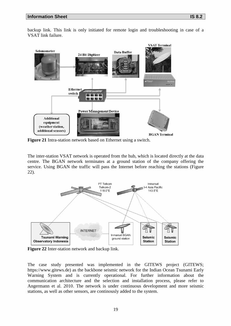
Step 4) Implementation of the communication system The intra-station network at all stations is based on Ethernet interfaces and a switch (Figure 21). The VSAT modem is configured to be the default gateway for all equipment on-site (intra-station network), so waveform data is transmitted using the VSAT network. In order to reduce maintenance costs, BGAN terminals are added at each station to provide a secondary
Information Sheet IS 8.2
19
backup link. This link is only initiated for remote login and troubleshooting in case of a VSAT link failure.
Figure 21 Intra-station network based on Ethernet using a switch. The inter-station VSAT network is operated from the hub, which is located directly at the data centre. The BGAN network terminates at a ground station of the company offering the service. Using BGAN the traffic will pass the Internet before reaching the stations (Figure 22).
Figure 22 Inter-station network and backup link. The case study presented was implemented in the GITEWS project (GITEWS; https://www.gitews.de) as the backbone seismic network for the Indian Ocean Tsunami Early Warning System and is currently operational. For further information about the communication architecture and the selection and installation process, please refer to Angermann et al. 2010. The network is under continuous development and more seismic stations, as well as other sensors, are continously added to the system.

Information Sheet IS 8.2
20
Appendix 2 List of manufacturers and products The following list of communication equipment manufacturers provides more details for further reading.
Category System Product Manufacturer Web Link
Wired communication
technologies
RS-232 PCI cards StarTech: http://www.startech.com/
RS-485 Cards and converter SerialComm: http://www.serialcomm.com/ CommFront: http://www.commfront.com
100Base-T
PCI cards D-Link: http://www.dlink.com/ STP cable Belden: http://www.belden.com/
100Base-FX
PCI cards D-Link: http://www.dlink.com/ Fibre cable Corning: http://www.corning.com/ Transceiver EtherWAN: http://www.etherwan.com/
VDSL Ethernet extender StarTech: http://www.startech.com/ Allied Telesis: http://www.alliedtelesis.com/
Wireless communication
technologies
Wireless LAN
Modems Cisco: http://www.cisco.com/ Avalan: http://www.avalanwireless.com/
Long range systems Ubiquiti http://www.ubnt.com/ Afar: http://www.afar.net/
RF telemetry
Modems Avalan: http://www.avalanwireless.com/ Radiometrix: http://www.radiometrix.com/
Long range systems Freewave: http://www.freewave.com/
Mobile phone Modems
Cisco: http://www.cisco.com/ LyconSys: http://www.lyconsys.com/ NetModule: http://www.netmodule.com/ Insys: http://www.insys-icom.com/
Satellite communication
technologies
VSAT
Parabolic antennas Prodelin: http://www.prodelin.com/ Skyware: http://www.skywareglobal.com/ Andrew: http://www.andrew.com/
Receive and transmit units (LNB, BUC)
Belcom: http://www.belcommicrowaves.com/ Terrasat: http://www.terrasatinc.com/ New Japan Radio: http://www.njr.com/ Advantech: http://www.advantechwireless.com/
VSAT platforms/ Modems
IDirect: http://www.idirect.net/ Hughes: http://www.hughes.com/ Gilat: http://www.gilat.com/ Viasat: http://www.viasat.com/ Nanometrics: http://www.nanometrics.ca/
Cables and connectors
Belden: http://www.belden.com/ Cablecon: http://www.cabelcon.dk/
BGAN Terminals Thrane & Thrane: http://www.cobham.com/ Addvalue: http://www.wideye.com.sg/ Hughes: http://www.hughes.com/
Thuraya Terminals Thuraya: http://www.thuraya.com/ Iridium Terminals Iridium: http://www.iridium.com/