Topic 9: Electric Forces - Fermilab Science Education...
28
Topic 9: Electric Forces Source: Conceptual Physics textbook, lab book and CPO textbook and lab book Types of Materials: Textbooks, lab books, worksheets, demonstrations/activities, vectors and websites, and good stories Building on: With much of mechanics presented at this point, electric force and all related electronic topics such as voltage, current, transistors and circuits become an extension to the force field concept, force, motion, the inverse square law, vectors and other topics previously studied. Links to Physics: The understanding of electric forces will lead to the understanding of electrostatics and electric circuits. The electric force concept will be used in the later topics of nuclear behavior like radiation, high-energy accelerators as at Fermilab and many chemistry applications. The transistor and all the electronics that followed, including the blackberry, have revolutionized electronics and the world’s economy. Links to Chemistry: Chemistry uses this topic to explain ionization, electrolysis, formation of molecules, radiation, microscopy, Coulomb’s force law in the atom, the study of physical chemistry and other items. Forces between electrons and protons and their location in the atom explain their potential energy, thus, their ionization energies. The properties of the elements are based on the valence electrons. Electron configuration also explains bonding, electronegativity, and heat conduction and charge conduction by metals. Links to Biology: As in chemistry, the electric force is needed to understand the formation of molecules. Biophysics and molecular biology will use the ideas about electric force and electric fields to continue research in microscopy. Ions or electrolytes in cells and the bloodstream are understood using electric forces. Materials: (a) Hewitt Static Cling (b) Hsu Observing Electric Charge (c) My Lab Conceptual Coulombs Law
Transcript of Topic 9: Electric Forces - Fermilab Science Education...

Topic 9: Electric Forces
Source: Conceptual Physics textbook, lab book and CPO textbook and lab book
Types of Materials: Textbooks, lab books, worksheets, demonstrations/activities, vectors and
websites, and good stories
Building on: With much of mechanics presented at this point, electric force and all
related electronic topics such as voltage, current, transistors and circuits
become an extension to the force field concept, force, motion, the inverse
square law, vectors and other topics previously studied.
Links to Physics: The understanding of electric forces will lead to the understanding of
electrostatics and electric circuits. The electric force concept will be used
in the later topics of nuclear behavior like radiation, high-energy
accelerators as at Fermilab and many chemistry applications. The
transistor and all the electronics that followed, including the blackberry,
have revolutionized electronics and the world’s economy.
Links to Chemistry: Chemistry uses this topic to explain ionization, electrolysis, formation of
molecules, radiation, microscopy, Coulomb’s force law in the atom, the
study of physical chemistry and other items. Forces between electrons and
protons and their location in the atom explain their potential energy, thus,
their ionization energies. The properties of the elements are based on the
valence electrons. Electron configuration also explains bonding,
electronegativity, and heat conduction and charge conduction by metals.
Links to Biology: As in chemistry, the electric force is needed to understand the formation of
molecules. Biophysics and molecular biology will use the ideas about
electric force and electric fields to continue research in microscopy. Ions
or electrolytes in cells and the bloodstream are understood using electric
forces.
Materials:
(a) Hewitt
Static Cling
(b) Hsu
Observing Electric Charge
(c) My Lab
Conceptual Coulombs Law

(d) Worksheet
Electric Force Worksheet
(e) Demonstrations
1. Electrostatic Demos
2. Conduction and Induction Demo
3. Electric Field Demo
(f) Videos and Websites:
1. Understanding Electricity Video Guide
2. Electrostatic Lab Sims (Flash, Shockwave)
3. Electric Fields Lab Sim (Java)
4. http://www.hazelwood.K12.mo.us/~grichert/sciweb/electric.htm
(This site does an excellent demo on charge motion within the electroscope.
Some other related choices within the site need JAVA.)
5. http://ww.library.advanced.org/10796/ch12/ch12.htm
(This site compares the gravitational force field to the electric force field and
their derivation. This site is more for the teacher.)
6. http://www.compadre.org/precollege/static/unit.cfm?sb=9
(This site offers several selections for static electricity, demonstrations,
misconceptions, videos, electric field game (GREAT GAME—COULD
NOT STOP TRYING—shows vectors and is challenging).
(g) Good Stories:
1. Charles Coulomb
2. Charles Augustin Coulomb - Civil Engineer
3. Millikan’s Oil Drop Experiment
4. John Bardeen
Topic 9: Conceptual Coulomb’s Law Lab/Demo
Purpose: The purpose of this qualitative/quantitative lab/demo is to illustrate that the electric
force between two charges depends on the product of their charges.
F (electric) ! Q1 x Q2
Materials:
1. Use commercial charging plate or make one by gluing an insulating rod (glass, etc.)
to an aluminum Baker’s Square pie plate.
2. Make a conductive sphere. Coat a ping pong ball with graphite paint (conducting) and
glue a small loop to the ball and thread a 4 m nylon fish line to make a V and connect
this V to a tall support. (Suggestion: A conducting balloon might be better, having
less weight and more charge.)
3. Make a second graphite ping-pong ball and glue it to a glass rod.
4. Calibrate a 50 cm glass rod with a mark every 1 cm. (Use nail polish.)
5. Obtain a great charging device like a Van de Graaff, fur and plastic golf tube, or
electrophorus.
6. Support rods.
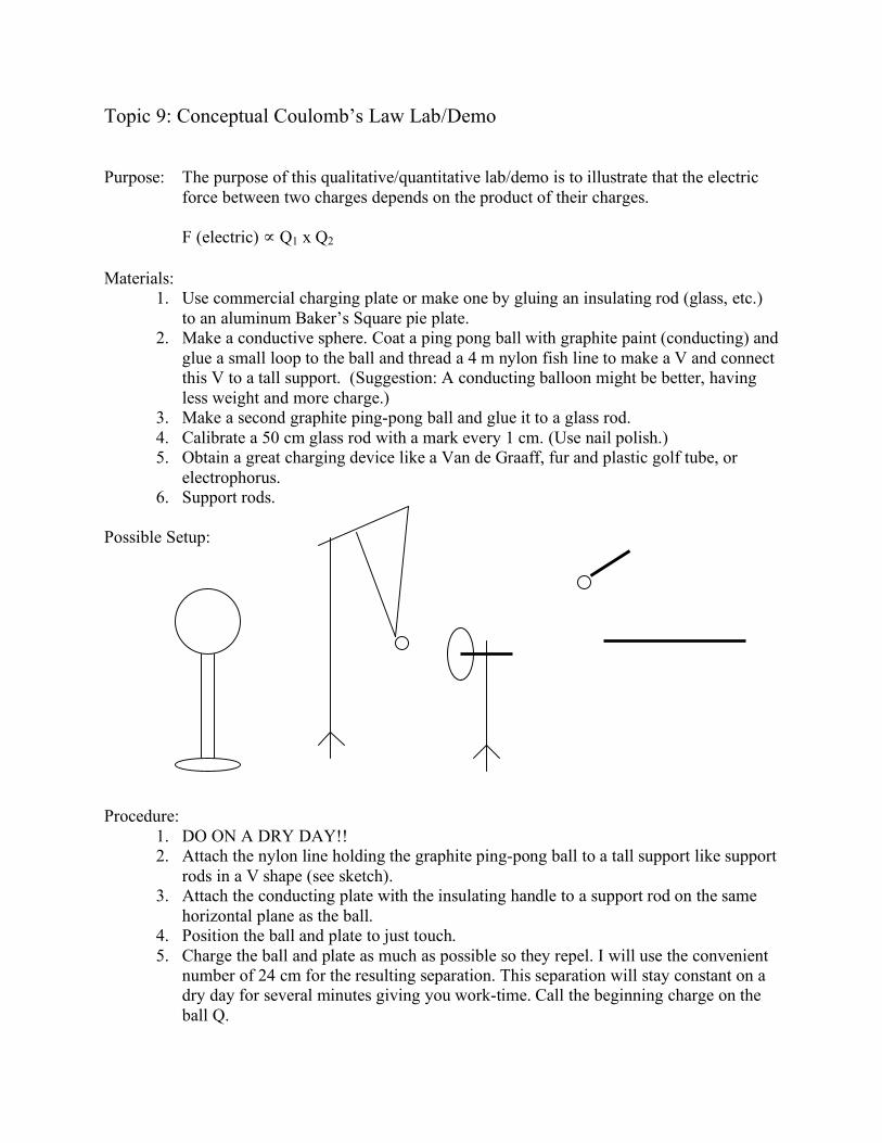
Possible Setup:
Procedure:
1. DO ON A DRY DAY!!
2. Attach the nylon line holding the graphite ping-pong ball to a tall support like support
rods in a V shape (see sketch).
3. Attach the conducting plate with the insulating handle to a support rod on the same
horizontal plane as the ball.
4. Position the ball and plate to just touch.
5. Charge the ball and plate as much as possible so they repel. I will use the convenient
number of 24 cm for the resulting separation. This separation will stay constant on a
dry day for several minutes giving you work-time. Call the beginning charge on the
ball Q.

6. Measure the separation distance between the center of the suspended ball and plate to
the nearest cm. Record in the table.
7. Without delay, touch the ball with the glass rod to the suspended ball and remove and
ground (touch it) the ball glued to the rod.
8. Measure the new separation with the new charge on the suspended ball at 1/2 of the
starting charge, or Q/2. Record.
9. Again, touch the uncharged ball on the glass rod to the suspended ball. Remove and
ground the ball glued to the glass rod. The suspended ball now has 1/2 of the previous
charge so 1/2 of Q/2 is Q/4, 1/4 of the original.
Data Table:
Trial Suspended Ball Charge Separation R between
Plate and Ball in (cm)
1 Q
2 Q/2
3 Q/4
Theory:
Coulomb’s law states: Fe = k Q1Q2 / R2, so, Fe ! Q1Q2.
Thus, F1 ! (Q1)(Q) = Q1Q
F2 ! (Q1)(Q/2) = Q1(Q/2) = Q1Q/2
F3 ! (Q1)(Q/4) = Q1(Q/4) = Q1Q/4
So, the three trials should result in the original force, then one-half the force and then one-fourth
the force.
How to do this???
Observe the displaced ball from the plate and the force vectors at work:

When the suspended ball is Similar ‘s show F(e) or F(g) = X
displaced as shown, the W L
outward electric force
matches the gravity Since W and L are constant, F(e) ! X.
component F(g). L
The weight (W)
of the ball is (W).
F(e)
X
F(g)
W
F(g)
From the sketch above, as the charge on the suspended ball reduces, so does the displacement
(X). To make X one-half as much requires halving the force on the suspended ball. Reducing the
force to half as much is accomplished by halving the charge. Halving the charge again to one-
fourth as much means the force is one-fourth as much. Example: If X is at 24 cm with a charge
of Q, X would be 12 cm at 1/2 and 6 cm at Q/4.
Analysis:
1. Qualitatively, does the electric force get less when the charge on the suspended ball gets
less?
________________________________________________________________________
2. Quantitatively, does the electric force halve when the charge halves?
________________________________________________________________________
3. Quantitatively, does the electric force quarter when the charge quarters?
________________________________________________________________________
4. What would happen to the electric force if the charge on the suspended ball were halved
again?
________________________________________________________________________
5. What would happen to the distance between the suspended ball and plate, if when the
charge were halved again (see question 4)?
________________________________________________________________________
Topic 9: Conceptual Coulomb’s Law Lab/Demo Answer Sheet
Purpose: The purpose of this qualitative/quantitative lab/demo is to illustrate that the electric
force between two charges depends on the product of their charges.
F (electric) ! Q1 x Q2
Materials:
1. Use commercial charging plate or make one by gluing an insulating rod (glass, etc.)
to an aluminum Baker’s Square pie plate.
2. Make a conductive sphere. Coat a ping pong ball with graphite paint (conducting) and
glue a small loop to the ball and thread a 4 m nylon fish line to make a V and connect
this V to a tall support. (Suggestion: A conducting balloon might be better, having
less weight and more charge.)
3. Make a second graphite ping-pong ball and glue it to a glass rod.
4. Calibrate a 50 cm glass rod with a mark every 1 cm. (Use nail polish.)
5. Obtain a great charging device like a Van de Graaff, fur and plastic golf tube, or
electrophorus.
6. Support rods.
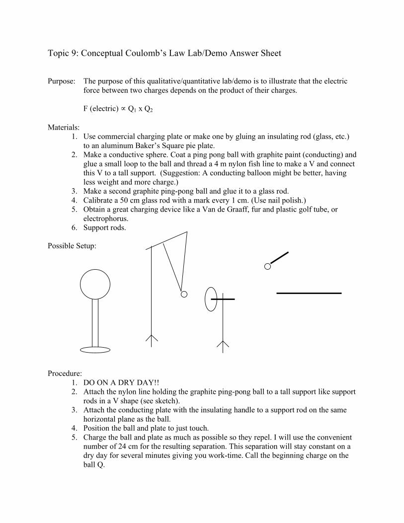
Possible Setup:
Procedure:
1. DO ON A DRY DAY!!
2. Attach the nylon line holding the graphite ping-pong ball to a tall support like support
rods in a V shape (see sketch).
3. Attach the conducting plate with the insulating handle to a support rod on the same
horizontal plane as the ball.
4. Position the ball and plate to just touch.
5. Charge the ball and plate as much as possible so they repel. I will use the convenient
number of 24 cm for the resulting separation. This separation will stay constant on a
dry day for several minutes giving you work-time. Call the beginning charge on the
ball Q.

6. Measure the separation distance between the center of the suspended ball and plate to
the nearest cm. Record in the table.
7. Without delay, touch the ball with the glass rod to the suspended ball and remove and
ground (touch it) the ball glued to the rod.
8. Measure the new separation with the new charge on the suspended ball at 1/2 of the
starting charge, or Q/2. Record.
9. Again, touch the uncharged ball on the glass rod to the suspended ball. Remove and
ground the ball glued to the glass rod. The suspended ball now has 1/2 of the previous
charge so 1/2 of Q/2 is Q/4, 1/4 of the original.
Data Table:
Trial Suspended Ball Charge Separation R between
Plate and Ball in (cm)
1 Q
24
2 Q/2
12
3 Q/4
6
Theory:
Coulomb’s law states: Fe = k Q1Q2 / R2, so, Fe ! Q1Q2.
Thus, F1 ! (Q1) (Q) = Q1Q
F2 ! (Q1) (Q/2) = Q1 (Q/2) = Q1Q/2
F3 ! (Q1) (Q/4) = Q1 (Q/4) = Q1Q/4
So, the three trials should result in the original force, then one-half the force and then one-fourth
the force.
How to do this??? (Method given below)
Observe the displaced ball from the plate and the force vectors at work:

When the suspended ball is Similar ‘s show F(e) or F(g) = X
displaced as shown, the W L
outward electric force
matches the gravity Since W and L are constant, F(e) ! X.
component F(g). L
The weight (W)
of the ball is (W).
F(e)
X
F(g)
W
F(g)
From the sketch above, as the charge on the suspended ball reduces, so does the displacement
(X). To make X one-half as much requires halving the force on the suspended ball. Reducing the
force to half as much is accomplished by halving the charge. Halving the charge again to one-
fourth as much means the force is one-fourth as much. Example: If X is at 24 cm with a charge
of Q, X would be 12 cm at 1/2 and 6 cm at Q/4.
Analysis:
1. Qualitatively, does the electric force get less when the charge on the suspended ball gets
less?
Yes
2. Quantitatively, does the electric force halve when the charge halves?
Yes—shown as X becomes 12 cm, so F is !.
3. Quantitatively, does the electric force quarter when the charge quarters?
Yes. X goes to 6 cm, so F is ".
4. What would happen to the electric force if the charge on the suspended ball were halved
again?
F halves to ! of " or 1/8.
5. What would happen to the distance between the suspended ball and plate, if when the
charge were halved again (see question 4)?
X halves to 3 cm.
Topic 9: Electric Forces Worksheet
Electrical Background:
1. Two charges exist in nature, the plus (+) and negative (-).
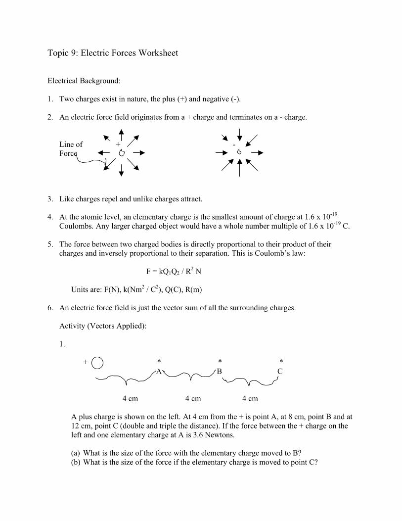
2. An electric force field originates from a + charge and terminates on a - charge.
Line of + -
Force
3. Like charges repel and unlike charges attract.
4. At the atomic level, an elementary charge is the smallest amount of charge at 1.6 x 10⁻¹⁹
Coulombs. Any larger charged object would have a whole number multiple of 1.6 x 10⁻¹⁹
C.
5. The force between two charged bodies is directly proportional to their product of their
charges and inversely proportional to their separation. This is Coulomb’s law:
F = kQ1Q2 / R2 N
Units are: F(N), k(Nm2 / C
2), Q(C), R(m)
6. An electric force field is just the vector sum of all the surrounding charges.
Activity (Vectors Applied):
1.
+ + * * *
A B C
4 cm 4 cm 4 cm
A plus charge is shown on the left. At 4 cm from the + is point A, at 8 cm, point B and at
12 cm, point C (double and triple the distance). If the force between the + charge on the
left and one elementary charge at A is 3.6 Newtons.
(a) What is the size of the force with the elementary charge moved to B?
(b) What is the size of the force if the elementary charge is moved to point C?
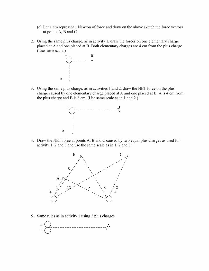
(c) Let 1 cm represent 1 Newton of force and draw on the above sketch the force vectors
at points A, B and C.
2. Using the same plus charge, as in activity 1, draw the forces on one elementary charge
placed at A and one placed at B. Both elementary charges are 4 cm from the plus charge.
(Use same scale.)
+ B
A
3. Using the same plus charge, as in activities 1 and 2, draw the NET force on the plus
charge caused by one elementary charge placed at A and one placed at B. A is 4 cm from
the plus charge and B is 8 cm. (Use same scale as in 1 and 2.)
+ B
A
4. Draw the NET force at points A, B and C caused by two equal plus charges as used for
activity 1, 2 and 3 and use the same scale as in 1, 2 and 3.
B C
8
A
4 12 8 8 8
+ +
5. Same rules as in activity 1 using 2 plus charges.
+ A
+

6. Same rules as in activity 1 using 2 plus charges.
4
4 4
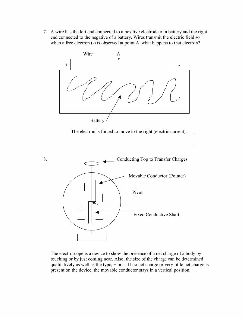
7. A wire has the left end connected to a positive electrode of a battery and the right end
connected to the negative of a battery. Wires transmit the electric field, so when a free
electron (-) is observed at point A, what happens to that electron?
Wire A
+ -
Battery
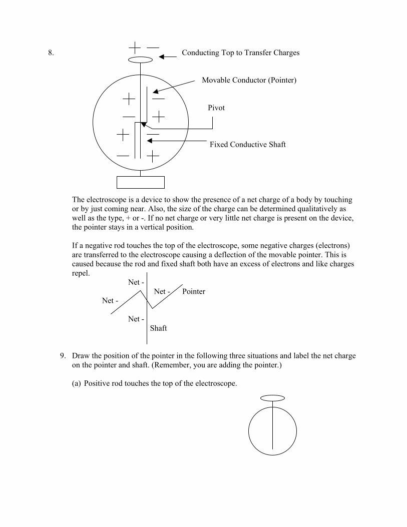
8. Conducting Top to Transfer Charges
Movable Conductor (Pointer)
Pivot
Fixed Conductive Shaft
The electroscope is a device to show the presence of a net charge of a body by touching
or by just coming near. Also, the size of the charge can be determined qualitatively as
well as the type, + or -. If no net charge or very little net charge is present on the device,
the pointer stays in a vertical position.
If a negative rod touches the top of the electroscope, some negative charges (electrons)
are transferred to the electroscope causing a deflection of the movable pointer. This is
caused because the rod and fixed shaft both have an excess of electrons and like charges
repel.
Net -
Net - Pointer
Net -
Net -
Shaft
9. Draw the position of the pointer in the following three situations and label the net charge
on the pointer and shaft. (Remember, you are adding the pointer.)
(a) Positive rod touches the top of the electroscope.

(b) Positive body comes near the top of the electroscope.
(c) Negative body comes near the top of the electroscope.
Topic 9: Electric Forces Worksheet Answer Sheet
Electrical Background:
1. Two charges exist in nature, the plus (+) and negative (-).
2. An electric force field originates from a + charge and terminates on a - charge.
Line of + -
Force
3. Like charges repel and unlike charges attract.
4. At the atomic level, an elementary charge is the smallest amount of charge at
1.6 x 10⁻¹⁹
Coulombs. Any larger charged object would have a whole number
multiple of 1.6 x 10⁻¹⁹
C.
5. The force between two charged bodies is directly proportional to their product of their
charges and inversely proportional to their separation. This is Coulomb’s law:
F = kQ1Q2 / R2 N
Units are: F(N), k(Nm2 / C
2), Q(C), R(m)
6. An electric force field is just the vector sum of all the surrounding charges.
Activity (Vectors Applied):
1. 3.6 cm 0.9 cm 0.4 cm
+ + * * *
A B C
4 cm 4 cm 4 cm
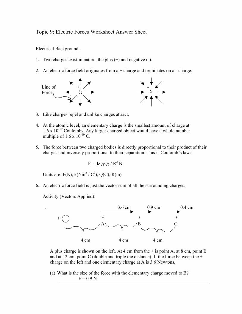
A plus charge is shown on the left. At 4 cm from the + is point A, at 8 cm, point B
and at 12 cm, point C (double and triple the distance). If the force between the +
charge on the left and one elementary charge at A is 3.6 Newtons,
(a) What is the size of the force with the elementary charge moved to B?
F = 0.9 N

(b) What is the size of the force if the elementary charge is moved to point C?
F = 0.4 N
(c) Let 1 cm represent 1 Newton of force and draw on the above sketch the force
vectors at points A, B and C.
See (a).
2. Using the same plus charge, as in activity 1, draw the forces on one elementary
charge placed at A and one placed at B. Both elementary charges are 4 cm from
the plus charge. (Use same scale.)
+ B
3.6 cm/N
A
3.6 cm/N
3. Using the same plus charge, as in activities 1 and 2, draw the NET force on the
plus charge caused by one elementary charge placed at A and one placed at B. A
is 4 cm from the plus charge and B is 8 cm. (Use same scale as in 1 and 2.)
+ B
0.9 cm/N
A
3.6 cm/N

4. Draw the NET force at points A, B and C caused by two equal plus charges as
used for activities 1, 2 and 3 and use the same scale as in 1, 2 and 3.
B C
8
A
4 12 8 8 8
+ +
5. Same rules as in activity 1 using 2 plus charges.
+ 8 A
+
6. Same rules as in activity 1 using 2 plus charges.
4 ZERO NET FORCE (cancels)
4 4
7. A wire has the left end connected to a positive electrode of a battery and the right
end connected to the negative of a battery. Wires transmit the electric field so
when a free electron (-) is observed at point A, what happens to that electron?
Wire A
+ -
Battery
The electron is forced to move to the right (electric current).
8. Conducting Top to Transfer Charges
Movable Conductor (Pointer)
Pivot
Fixed Conductive Shaft
The electroscope is a device to show the presence of a net charge of a body by
touching or by just coming near. Also, the size of the charge can be determined
qualitatively as well as the type, + or -. If no net charge or very little net charge is
present on the device, the movable conductor stays in a vertical position.

If a negative rod touches the top of the electroscope, some negative charges
(electrons) are transferred to the electroscope causing a deflection of the movable
pointer. This is caused because the pointer and fixed shaft both have an excess of
electrons and like charges repel.
Net -
Net - Pointer
Net -
Net -
Shaft
9. Draw the position of the pointer in the following three situations and label the net
charge on the pointer and shaft. (Remember, you are adding the pointer).
(a) Positive rod touches the top of the electroscope.
+
(b) Positive body comes near the top of the electroscope.
+
(c) Negative body comes near the tope of the electroscope.

Topic 9: Demonstrations – Electrostatics, Conduction-Induction, E Demo
(A) Electrostatics (Only doing ONE CLASSIC—too many to discuss.)
Purpose: To observe that like charges repel and unlike charges attract.
Procedure:
1. Obtain a quality Van de Graaff generator. Fine-tune by cleaning the top with alcohol and
a rag; use a newer belt that isn’t too loose; adjust the pick-up comb to grab electrons but
not touching the belt—try about 2 mm.
2. Obtain enough Styrofoam to support your largest football player about 20 cm off the
floor to prevent arching to the floor.
3. Tape five or so cotton threads about 20 cm long around the ball to look like hair. Turn on
for a few seconds to charge. Electrons are transferred from the base to the ball. The ball
and thread have the same charge so repel.
Uncharged Charged
4. Ask, “What would happen if we put a student on an insulating platform and charge
him/her up”? Choose the student(s) with the clean, thin and dry hair for a hair-raising
event. Blonde hair is thinner and tends to work best; shoulder length works nicely but
long hair can work too; trying several will always fake you out as to what should happen!
5. To discharge the student:
(a) Step down and watch and listen for the spark, or
(b) Hand the student a meter stick while you continue to hold on and charge will quickly
dissipate, but no spark; most students prefer keeping their charge to try to zap the
nearest student!
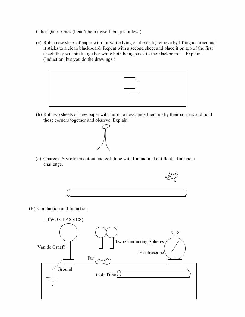
Other Quick Ones (I can’t help myself, but just a few.)
(a) Rub a new sheet of paper with fur while lying on the desk; remove by lifting a corner and
it sticks to a clean blackboard. Repeat with a second sheet and place it on top of the first
sheet; they will stick together while both being stuck to the blackboard. Explain.
(Induction, but you do the drawings.)
(b) Rub two sheets of new paper with fur on a desk; pick them up by their corners and hold
those corners together and observe. Explain.
(c) Charge a Styrofoam cutout and golf tube with fur and make it float—fun and a
challenge.
(B) Conduction and Induction
(TWO CLASSICS)
Two Conducting Spheres
Van de Graaff
Electroscope
Fur
Ground
Golf Tube

Charge of the Van de Graaff and Conduction and Induction
1. Touch each of the two uncharged conducting metal spheres to the uncharged electroscope.
Nothing happens since no net charge exists.
2. Test for the nature of the charge of the golf tube by rubbing the golf tube with the fur and
touch the electroscope. The scope will have the same charge as the tube, which is negative by
definition, because the fur transfers electrons onto the tube and they are transferred to the
electroscope by conduction (contact). When the tube is brought near the scope, repulsion
occurs between the excess electrons on the tube and excess electrons on the scope.
3. To determine the charge of the Van de Graaff, touch one of the uncharged spheres to the Van
de Graaff. Bring that sphere to the electroscope and touch it. Remove the sphere and let the
electroscope settle to a constant deflection. Bring the charged golf tube rubbed with fur
(negative) near the Van de Graaff to see if deflection or collapse occurs. Deflection means
like charge or negative and collapse means positive.
3. To illustrate induction, charge the Van de Graaff and bring the two uncharged spheres while
touching to around 3 cm from the Van de Graaff while keeping one sphere positioned close
and the second sphere far from the Van de Graaff. Separate the two spheres, keeping in mind,
which was near and far. Touch the near sphere to the electroscope and follow step 3. The
near sphere will be opposite the Van de Graaff or positive. Repeat for the far sphere that will
be negative. See the sketch below.
Left Start Right Start
4 + 4 - 4 + 4 -
Left End Right End
4 + 3 - 4 + 5 -
Net Plus Net Negative
1 e -
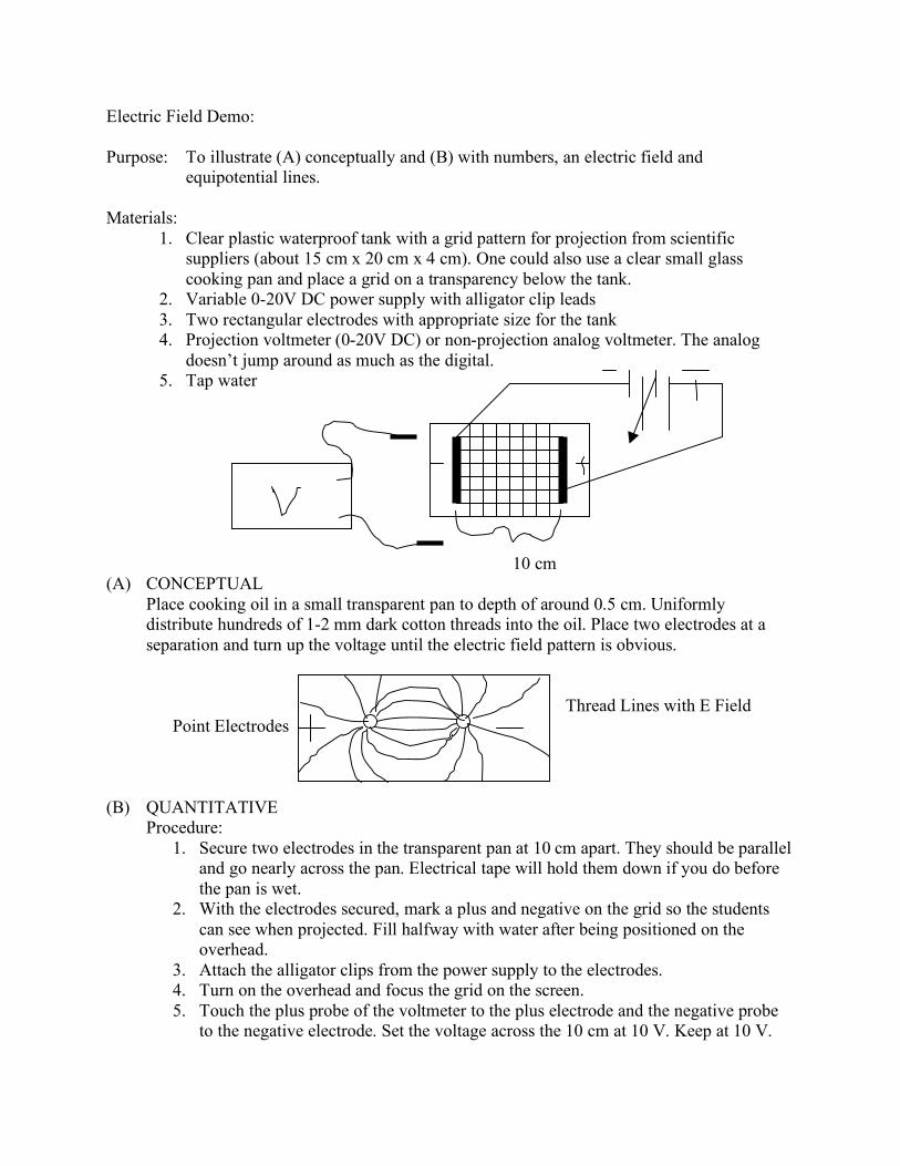
Electric Field Demo:
Purpose: To illustrate (A) conceptually and (B) with numbers, an electric field and
equipotential lines.
Materials:
1. Clear plastic waterproof tank with a grid pattern for projection from scientific
suppliers (about 15 cm x 20 cm x 4 cm). One could also use a clear small glass
cooking pan and place a grid on a transparency below the tank.
2. Variable 0-20V DC power supply with alligator clip leads
3. Two rectangular electrodes with appropriate size for the tank
4. Projection voltmeter (0-20V DC) or non-projection analog voltmeter. The analog
doesn’t jump around as much as the digital.
5. Tap water
10 cm
(A) CONCEPTUAL
Place cooking oil in a small transparent pan to depth of around 0.5 cm. Uniformly
distribute hundreds of 1-2 mm dark cotton threads into the oil. Place two electrodes at a
separation and turn up the voltage until the electric field pattern is obvious.
Thread Lines with E Field
Point Electrodes ++
(B) QUANTITATIVE
Procedure:
1. Secure two electrodes in the transparent pan at 10 cm apart. They should be parallel
and go nearly across the pan. Electrical tape will hold them down if you do before
the pan is wet.
2. With the electrodes secured, mark a plus and negative on the grid so the students
can see when projected. Fill halfway with water after being positioned on the
overhead.
3. Attach the alligator clips from the power supply to the electrodes.
4. Turn on the overhead and focus the grid on the screen.
5. Touch the plus probe of the voltmeter to the plus electrode and the negative probe
to the negative electrode. Set the voltage across the 10 cm at 10 V. Keep at 10 V.

6. Next, place the plus probe at the 8-cm line and the negative probe at the 6-cm line
IN THE WATER. What is the potential difference between the two lines measured
in volts?
2V
7. Repeat #6 between the 5 cm and 3 cm lines. What is this potential difference?
2V
8. Repeat #6 between the 4 cm and 2 cm lines. What is the potential difference?
2V
9. Discuss the meaning of the answers to 6, 7 and 8.
(The same energy per charge (voltage) occurs at equal spacing between parallel
electrodes.)
The electric field is defined as the force on a positive test charge or,
E = F / (+ q).
If the test charge is pushed in the direction of the field through a displacement of !
d and we multiply both sides of this definition by ! d the change in position, we
get:
!d (E) = !d (F) / +q.
Recall that force times the distance the force acts is work, so, ! d F = work (W).
Also, work per charge is voltage, so E = V/!d, or just
E = V/d.
The unit for the electric field is Newton per Coulomb or practically, volt per meter.
2 V/0.02 m = 100 V/m
10. Calculate the electric field in questions 6 (100 V/m), 7 (100 V/m) and 8 (100 V/m).
11. Guess the value of the electric field everywhere between the electrodes?
100 V/m

Check your guess by holding the probes at a 2 cm spacing and moving the probes to
many locations between the plates while keeping the probes perpendicular to the
electrodes.
DEMONSTRATE EQUIPOTENTIAL LINES
12. With the two voltmeter probes spaced at 2 cm, place the probes in the water on grid
lines that run parallel to the parallel electrodes. What is the reading?
0 V
13. Repeat 11 on a different parallel line. What is the reading?
0 V
These parallel lines are called equipotential lines since all points are at the same
potential energy value. Note that the equipotential lines are perpendicular to the
electric field lines.
FOLLOW-UP QUESTIONS:
Two-point source electrodes produce the following equipotential lines between the
electrodes. 3 V
2 V 4 V
1 V 5 V
+ A -
B C D
What would a voltmeter read placed at:
1. A and B? 2 V – 1 V = 1 V
2. B and C? 2 V – 1 V = 1 V
3. A and C? 2 V – 2 V = 0 V
4. B and D? 4 V – 1 V = 3 V

Charles Coulomb (1736-1806)
An interest in magnetism induced Charles Coulomb to enter a competition sponsored by
the Paris Academy of Science in 1777. He shared first prize for his paper on magnetic compasses
and an additional prize for his work on friction.
While Coulomb had been experimenting with compasses, he noticed that slight errors
were introduced by friction acting on the pivot that held the magnetized needle. He invented a
compass that had its needle suspended by a fine thread. The thread was an improvement, but it
twisted. Coulomb realized that the amount of twisting was related to the Earth’s magnetic field
applied to the needle. This led him to the invention of the torsion balance. (English geologist
John Michell is reported to have anticipated Coulomb by devising a torsion balance around
1750.) Coulomb developed a theory of torsion in silk and hair threads. Here he was the first to
show that this technique could accurately measure extremely small forces. The torsion principle
applied equally well to magnetic forces. It is interesting to note that he never actually calculated
the forces between the electrical charges or the magnetic poles. Instead, he verified that the force
between two electrical or two magnetic poles is inversely proportional to the square of the
distances between them.
Here it seems that once again Coulomb had been anticipated; Henry Cavendish had
independently discovered “Coulombs Law” but neglected to publish his work. Cavendish didn’t
come to light until fifty years after his death.

Charles Augustin Coulomb (1736-1806) – Civil Engineer
Coulomb was born to wealthy parents and grew up in Angouleme in southwestern
France. Henry Coulomb, Charles’ father, lost the family’s money through a series of bad
financial investments. His parents separated and Charles, after a disagreement with his mother
about his career choices, went to live with his father.
Although Charles had a fine education, he needed mathematics tutoring to secure his
admission to engineering school. He graduated as a lieutenant in the military Corp of Engineers
and spent several years building fortifications in the West Indies. On his return to France, he
continued his career as a civil engineer building windmills and other water works projects.
Coulomb made significant contributions to the field of civil engineering in the areas of
structural design, soil compaction, strength of materials and frictional forces in solid and fluids.
He recognized that different materials produce different amounts of friction and that the
frictional force in solid material is proportional to the normal force between the materials. He
developed a torsion balance that enabled him to study the forces between electric charges or
magnetic poles. Coulomb extended the concept of the torsion balance to the torsion pendulum
and by immersing the pendulum into a fluid observing the period of oscillation he could
determine the viscosity of a fluid.
Perhaps equally as great as his discoveries was his application of Newton’s calculus
throughout his work. Coulomb firmly established mathematics as the language of physics.

Millikan’s Oil Drop Experiment
Did Robert A. Millikan (1868-1953) design the famous experiment which helped him
earn a Nobel Prize?
Not entirely. Much of the credit should have gone to his graduate student Harvey
Fletcher, who was not even named co-author of the key relevant paper. Originally Millikan
experimented with water drops but unfortunately the single droplet had evaporated too quickly to
allow for accurate measurements. Fletcher was assigned the job of finding a suitable liquid for
the experiment. He immediately got a crude apparatus working using tiny droplets of watch oil
made with an atomizer he bought in a drug store. When Fletcher got the busy Millikan to look
through the telescope at the dancing (Brownian motion) suspended oil droplets, all work with
water ceased.
A couple years later the team had the results they were after and were aware of its
significance. Millikan approached Fletcher with a deal. Fletcher, as sole author, would publish a
paper on Brownian motion for his Ph.D. and Millikan would be the sole author on the unit
electric charge (e-) work. There is little doubt that both men understood the implications.
Millikan would take sole credit for the work on the electric charge,“e-,” and establish his
reputation. Fletcher, although, disappointed, accepted the deal. This incident was the source of
rumors that Millikan mistreated his graduate students.
The two men remained friends but Fletcher saw to it that this version of the story was
published: after the death of both men.

John Bardeen
In was in the spring of 1947, at Bell Labs, that the team of William Shockley, Walter
Brattain and John Bardeen made one of the greatest discoveries in the field of science and
technology. The transistor.
The discovery started out as a problem Shockley had put to Brattain and Bardeen.
Shockley had developed an amplifier that didn’t work and asked the team to find out why. At the
heart of the amplifier was a crystal made of silicon (several months later the silicon would be
replaced by germanium). To figure out what was going on, Bardeen had to remember some of
the quantum mechanics research that he had done on semiconductors at Princeton. John had
some new theories he was working on.
By observing Walter Brattain’s experiments, Bardeen realized that everyone had been
assuming electrical current traveled through all parts of the germanium in a similar way. That
was wrong! Electrons behaved differently at the surface of the metal. If Brattain and Bardeen
could control what was happening at the surface, the amplifier should work. It took more than six
months but they had succeeded. They had built the first point contact transistor. After the
invention of the transistor, the mood in the lab soured. Shockley was resentful that he missed the
invention. Not to be outdone, Shockley advanced the design on his own by developing the more
stable junction or sandwich transistor.
It was a Thursday morning in November in 1956, when John Bardeen was making
breakfast and listening to the radio. As he scrambled eggs he heard an announcement that the
Nobel Prize in Physics had been awarded to him, Walter Brattain and William Shockley for the
invention of the transistor.