V& op papIER - ESF · V&-logboek, STC Limburg & STC Turnhout Juni 2003 V& op papIER >> V& logboek
date post
20-Dec-2015Category
view
232download
3
Topic 3: Op-Amp: Golden Rules of OP Amp
1. iin=0, no current flow into op amp.
2. V+=V-
• Typically one end of op amp is connected to ground, therefore, V+=V-= 0V, virtual ground. Often V+ is connected to ground to avoid stability problem.
3. Various circuits: amplifier, sum and abstract, differentiator, integrator, etc.

Example
• What does the following circuit do? That is, find an expression for the gain and give the circuit a suitable name.

Example II
(a) (7pts)The circuit is an integrate circuit. Derive vout(t). RS=10 kΩ, CF=0.008 µF.
(b) (5pts)If the input signal vin=sin(2000πt) V, calculate vout(t) and the peak amplitude.
(c) (3pts)If the input signal vin=10 mV, calculate vout(t) and vout(t=100ms)
(d) (3pts)Op-amp is saturated when the output voltage reach the power supply voltage,
±15V in this case. At what time does the integration of the DC input cause the op-amp to
saturated fully?(e) (7pts) If the input signal is now
vin=0.01+ sin(2000πt) V, describe what happens to the output waveform till the op-amp is fully saturated.
2000cos2 125)( e.
ms 120)(12.0 d.
(V) 5.12)100(
(V) 125)( c.
(V) 2000cos2 .
125001
a.
tttv
Sect
msv
ttv
tvb
dtvdtvCR
v
out
out
out
out
ininFS
out

Example 4Design an op-amp circuit to convert the triangular waveform v1 in the following Figure into the
square wave vo shown. Use 0.1 F capacitor. (Hints: First quantitatively determine the
mathematical expression of vo in terms of v1 ).
kR
R
dt
dvCRv
F
F
SF
25101
2.0101.05.0
36
10
v1(t)

Topic 4: Filters
• Low-pass filters (LP)
RCe
RC
eRC
e
e
RCRCj
RCj
CjjH
jVZZ
ZjV
jV
jVjH
j
RCj
RCj
j
V
iRC
C
iV
1 ;
1
1
1
1
1
1
1
1
1
1
0/tan
2
tan
2
1tan
0
2
0
0
01
1
1

Active Filter
S
F
S
out
Z
Z
V
V
S
F
S
out
Z
Z
V
V1
It is phasor time again
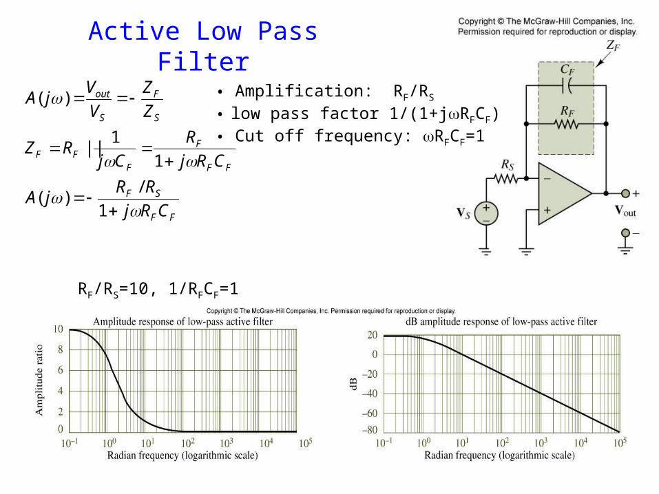
Active Low Pass Filter
FF
SF
FF
F
FFF
S
F
S
out
CRj
RRjA
CRj
R
CjRZ
Z
Z
V
VjA
1
/)(
1
1||
)( • Amplification: RF/RS
• low pass factor 1/(1+jRFCF)• Cut off frequency: RFCF=1
RF/RS=10, 1/RFCF=1

Band-pass Filters and Resonant Circuits
0
0
arctan
2
0
0
2
0
0
1
1
1
1
Q
V
e
Q
jQ
jH
LC
10
12
000
BR
LQ
Resonant frequency
Quality factor

RLC Resonant
CL ZZ
CjLj
CL
1
1
when 0
R
V
CLR
VI
CLjR
V
ZZZ
jVjI
CLR
22 1
1
)(
At resonance:• current is max.• Zeq =R• current and voltage are in phase.• the higher Q, the narrower the resonant peak.
Applications: tuning circuit

Example
RC
jCjR
R
v
vVH
in
out
1
11
980102802
1
11
6
R
RCkHzf
Req
67.11026.472
1
6.4798050
98050
6
a. Write the transfer function for this filter. (Both Vin and Vout are referenced to ground).
b). Design a high-pass RC filter with a characteristic frequency of 80 Hz using a capacitor of 2.0 F.c). What is the new characteristic frequency when the filter is loaded with 50 ohm?
How do you solve the problem:
Use small R or use active filter
SS
S
F
SS
F
S
F
S
out
CRjR
R
CjR
R
Z
Z
V
VjA
11
11
)(

Example 2
The circuit shown in an active filter. Determine: The voltage transfer function. The pass-band gain.
RF
Ri
v+
6.145
6811
11
11
1
0
0
0
1
i
F
i
i
F
i
F
Fci
R
RG
CRjR
R
v
v
CjR
R
v
vv
R
vv
ZR
v
vv

Exam 3
kRkR
CR
R
R
FS
FF
S
F
10 ;1 :say slet'
,1
1010
100
1
11.0101010 641
FFCR
The input signal can be written as Vi=10mV(sin10t+sin10,000t). Design a circuit so that the output signal is V0=-100mVsin10t. In another words, the high frequency signal has to be much smaller (<1%) than the low frequency part.
FF
SF
S
out
CRj
RR
V
VjA
1
/)(
FC
CR
CR
CRj
RR
F
FF
FF
FF
SF
11010
100
100
100
1
1
1
10
1
1
/
44
2
22
2
Low frequency
high frequency
Check low freq.

Topic 5: Electromachine
• Motion Electricity (generator): Magnetic Induction, Faraday’s law
• Electricity Motion (motor): force on a current, torque• Three phase power: structure, advantages.