Topic 14 - How CPU works
11
Topic 14 Slide 1 PYKC 9 June 2020 DE 1.3 - Electronics 1 Topic 14 How CPU works? URL: www.ee.ic.ac.uk/pcheung/teaching/DE1_EE/ E-mail: [email protected] Professor Peter YK Cheung Dyson School of Design Engineering
Transcript of Topic 14 - How CPU works

Topic 14 Slide 1 PYKC 9 June 2020 DE 1.3 - Electronics 1
Topic 14
How CPU works?
URL: www.ee.ic.ac.uk/pcheung/teaching/DE1_EE/ E-mail: [email protected]
Professor Peter YK Cheung Dyson School of Design Engineering

Topic 14 Slide 2 PYKC 9 June 2020 DE 1.3 - Electronics 1
A Very Simple Central Processing Unit ◆ Based on von Neumann model ◆ Stored program and data in memory ◆ Central Processing Unit (CPU)
contains: • Arithmetic/Logic Unit (ALU) • Control Unit • Registers
CPU
Memory
I/O
◆ Look into memory, sees ‘1’ and ‘0’. Meaning depends on context. ◆ All computers requires at least three types of signals (buses):
❖ address bus - which location ❖ data bus - carries the contents of the location ❖ control bus - governs the information transfer

Topic 14 Slide 3 PYKC 9 June 2020 DE 1.3 - Electronics 1
A Very Simple CPU

Topic 14 Slide 4 PYKC 9 June 2020 DE 1.3 - Electronics 1
A Very simple CPU
◆ Let us design a simple processor MU0 with 16-bit instruction and minimal hardware:- • Program Counter (PC) - holds address of the next instruction to exec • Accumulator (ACC) - holds data being processed • Arithmetic Logic Unit (ALU) - performs operations on data • Instruction Register (IR) - holds current instruction code being executed
◆ Let us further assumes that the processor only has 8 instructions and can only access a maximum of 4k 16-bit words (212) of memory.
◆ The 16-bit instruction code (machine code) has a format:
◆ Note top 4 bits define the operation code (opcode) and the bottom 12 bits define the memory address of the data

Topic 14 Slide 5 PYKC 9 June 2020 DE 1.3 - Electronics 1
Instruction Set
0
1
2
3
4
5
6
7
Topic 14 Slide 6 PYKC 9 June 2020 DE 1.3 - Electronics 1
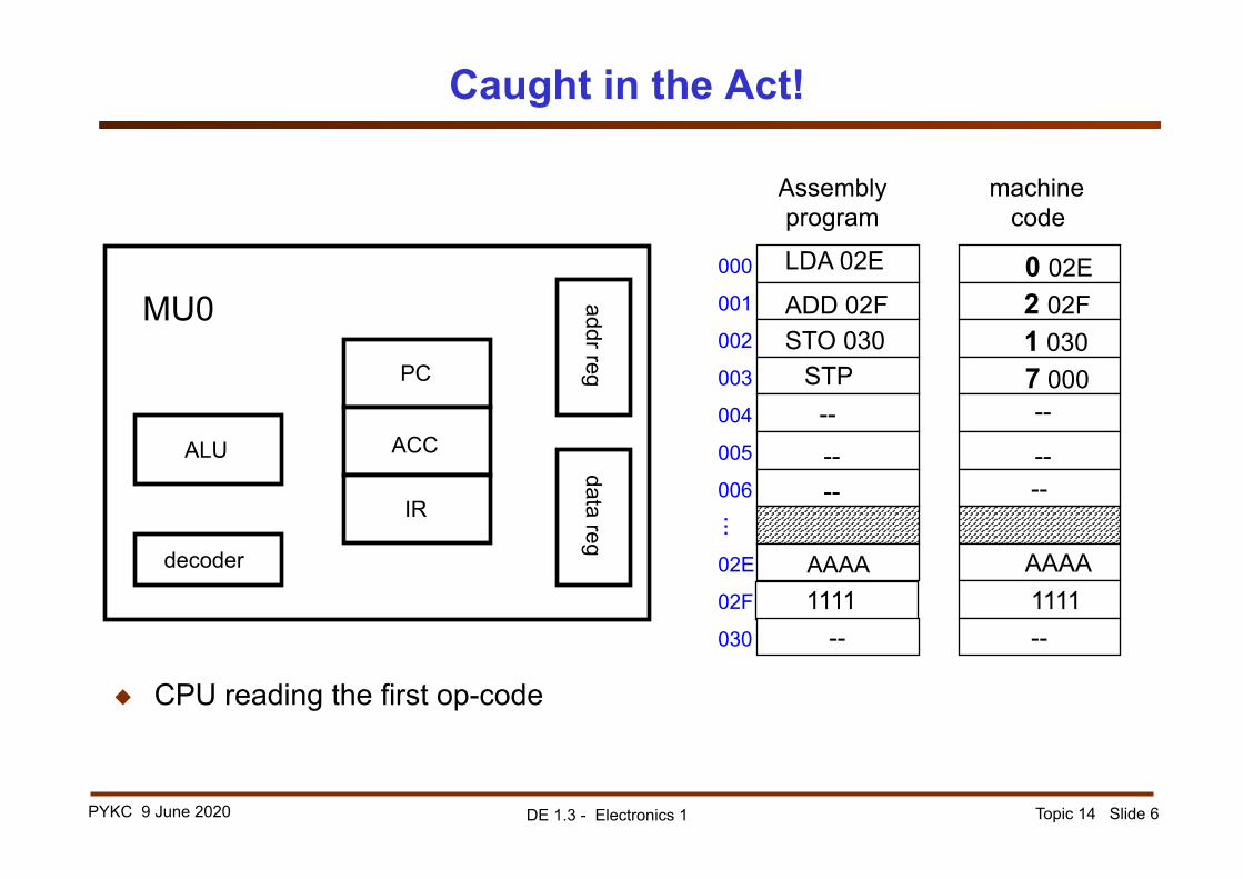
Caught in the Act!
◆ CPU reading the first op-code
PC ACC
IR decoder
ALU
addr reg data reg
MU0 000 LDA 02E 0 02E
Assembly program machine
code
001 ADD 02F 2 02F 002 STO 030 1 030 003 STP 7 000 004 -- 005 006
-- --
02E AAAA AAAA 02F 1111 1111 030 -- --
... --
-- --

Topic 14 Slide 7 PYKC 9 June 2020 DE 1.3 - Electronics 1
Instruction 1: LDA 02E
PC=000 ACC
IR=002E decoder
ALU
addr reg data reg
MU0 0 02E
machine code
2 02F 1 030 7 000
-- AAAA 1111 --
-- --
PC = 001 ACC=AAAA IR=002E decoder
ALU addr reg
data reg MU0
Cycle 1
Cycle 2
000 001 002 003 004 005 006 02E 02F 030
...
Fetch Instruction
Read Data

Topic 14 Slide 8 PYKC 9 June 2020 DE 1.3 - Electronics 1
Instruction 2: ADD 02F
PC=001 ACC=AAAA IR=202F decoder
ALU
addr reg data reg
MU0 0 02E
machine code 2 02F 1 030 7 000
-- AAAA 1111 --
-- --
PC=002 ACC=AAAA
IR=202F decoder
ALU addr reg
data reg MU0
Cycle 1
Cycle 2
000 001 002 003 004 005 006 02E 02F 030
...
Fetch Instruction
Do ADD

Topic 14 Slide 9 PYKC 9 June 2020 DE 1.3 - Electronics 1
Instruction 3: ST0 030
PC=002 ACC=BBBB
IR=1030 decoder
ALU
addr reg data reg
MU0 0 02E
machine code 2 02F 1 030 7 000
-- AAAA 1111 BBBB
-- --
PC=003 ACC=BBBB IR=1030 decoder
ALU addr reg
data reg MU0
Cycle 1
Cycle 2
000 001 002 003 004 005 006 02E 02F 030
...
Fetch Instruction
Write Data

Topic 14 Slide 10 PYKC 9 June 2020 DE 1.3 - Electronics 1
Instruction 4: STP
PC=003 ACC=BBBB
IR=7000 decoder
ALU
addr reg data reg
MU0 0 02E
machine code 2 02F 1 030 7 000
-- AAAA 1111 BBBB
-- --
Cycle 1
000 001 002 003 004 005 006 02E 02F 030
...
Fetch Instruction

Topic 14 Slide 11 PYKC 9 June 2020 DE 1.3 - Electronics 1
A video on “How a CPU is made?”