Topic 10 - Seismic Design of Steel Structures - · PDF fileFEMA 451B Topic 10 Notes Steel...
120
FEMA 451B Topic 10 Notes Steel Structures 10 - 1 Steel Structures 10 - 1 Instructional Material Complementing FEMA 451, Design Examples NEHRP RECOMMENDED PROVISIONS SEISMIC DESIGN OF STEEL STRUCTURES • Context in NEHRP Recommended Provisions • Steel behavior • Reference standards and design strength • Moment resisting frames • Braced frames • Other topics • Summary Table of contents. Note that most of the substance, except the first two items, is taken from AISC’s Seismic Provision for Steel Buildings, which is referenced by the NEHRP Recommended Provisions. Some of the examples in this topic draw heavily on the FEMA 451, NEHRP Recommended Provisions: Design Examples. Please see this CD for additional details.
Transcript of Topic 10 - Seismic Design of Steel Structures - · PDF fileFEMA 451B Topic 10 Notes Steel...

FEMA 451B Topic 10 Notes Steel Structures 10 - 1
Steel Structures 10 - 1Instructional Material Complementing FEMA 451, Design Examples
NEHRP RECOMMENDED PROVISIONSSEISMIC DESIGN OF STEEL STRUCTURES
• Context in NEHRP Recommended Provisions
• Steel behavior
• Reference standards and design strength
• Moment resisting frames
• Braced frames
• Other topics
• Summary
Table of contents. Note that most of the substance, except the first two items, is taken from AISC’s Seismic Provision for Steel Buildings, which is referenced by the NEHRP Recommended Provisions.Some of the examples in this topic draw heavily on the FEMA 451, NEHRP Recommended Provisions: Design Examples. Please see this CD for additional details.
FEMA 451B Topic 10 Notes Steel Structures 10 - 2
Steel Structures 10 - 2Instructional Material Complementing FEMA 451, Design Examples
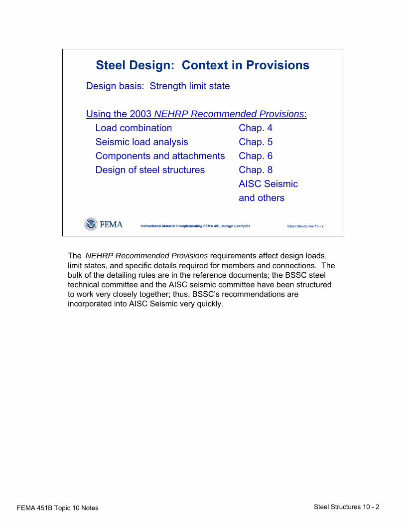
Steel Design: Context in ProvisionsDesign basis: Strength limit state
Using the 2003 NEHRP Recommended Provisions:Load combination Chap. 4Seismic load analysis Chap. 5Components and attachments Chap. 6Design of steel structures Chap. 8
AISC Seismicand others
The NEHRP Recommended Provisions requirements affect design loads, limit states, and specific details required for members and connections. The bulk of the detailing rules are in the reference documents; the BSSC steel technical committee and the AISC seismic committee have been structured to work very closely together; thus, BSSC’s recommendations are incorporated into AISC Seismic very quickly.
FEMA 451B Topic 10 Notes Steel Structures 10 - 3
Steel Structures 10 - 3Instructional Material Complementing FEMA 451, Design Examples
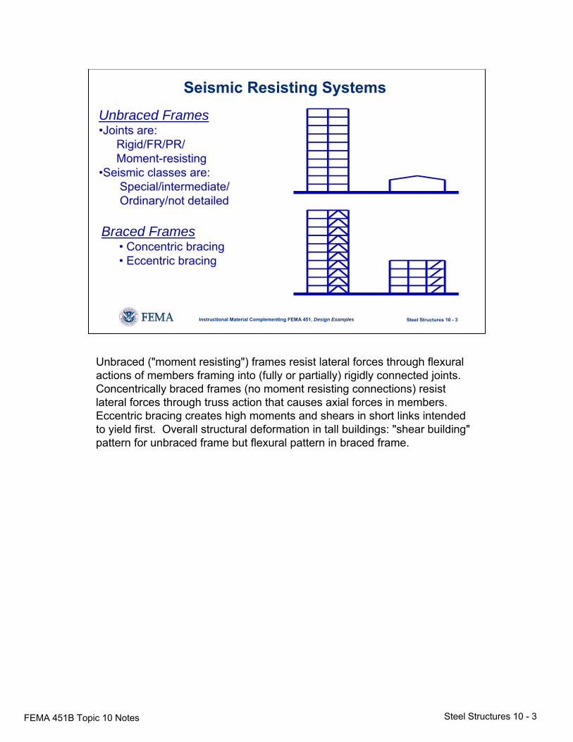
Seismic Resisting SystemsUnbraced Frames•Joints are:
Rigid/FR/PR/Moment-resisting
•Seismic classes are:Special/intermediate/Ordinary/not detailed
Braced Frames• Concentric bracing• Eccentric bracing
Unbraced ("moment resisting") frames resist lateral forces through flexural actions of members framing into (fully or partially) rigidly connected joints. Concentrically braced frames (no moment resisting connections) resist lateral forces through truss action that causes axial forces in members. Eccentric bracing creates high moments and shears in short links intended to yield first. Overall structural deformation in tall buildings: "shear building" pattern for unbraced frame but flexural pattern in braced frame.
FEMA 451B Topic 10 Notes Steel Structures 10 - 4
Steel Structures 10 - 4Instructional Material Complementing FEMA 451, Design Examples
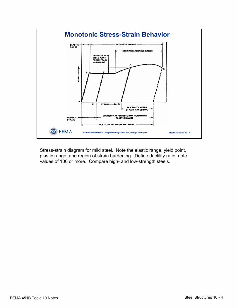
Monotonic Stress-Strain Behavior
Stress-strain diagram for mild steel. Note the elastic range, yield point, plastic range, and region of strain hardening. Define ductility ratio; note values of 100 or more. Compare high- and low-strength steels.
FEMA 451B Topic 10 Notes Steel Structures 10 - 5
Steel Structures 10 - 5Instructional Material Complementing FEMA 451, Design Examples
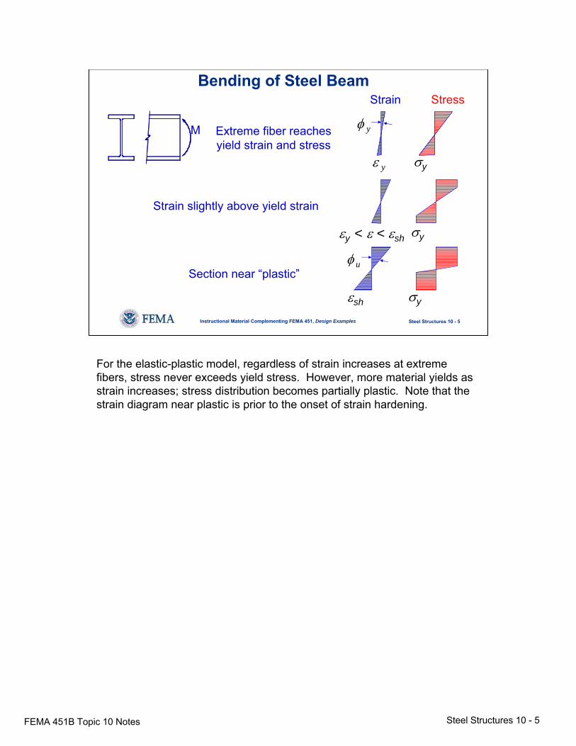
Bending of Steel Beam
M
Strain slightly above yield strain
Section near “plastic”
Extreme fiber reachesyield strain and stress
φ u
ε y
Strain Stress
φ y
εy < ε < εsh σy
σy
σy
εsh
For the elastic-plastic model, regardless of strain increases at extreme fibers, stress never exceeds yield stress. However, more material yields as strain increases; stress distribution becomes partially plastic. Note that the strain diagram near plastic is prior to the onset of strain hardening.
FEMA 451B Topic 10 Notes Steel Structures 10 - 6
Steel Structures 10 - 6Instructional Material Complementing FEMA 451, Design Examples
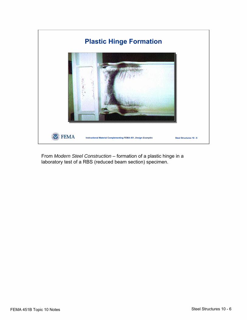
Plastic Hinge Formation
From Modern Steel Construction – formation of a plastic hinge in a laboratory test of a RBS (reduced beam section) specimen.
FEMA 451B Topic 10 Notes Steel Structures 10 - 7
Steel Structures 10 - 7Instructional Material Complementing FEMA 451, Design Examples
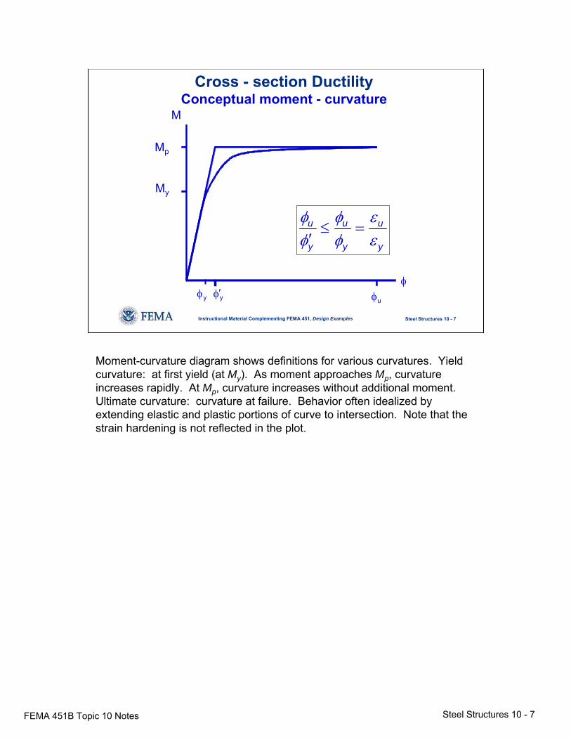
Cross - section DuctilityConceptual moment - curvature
M
yφ′
Mp
My
yφ uφφ
u u u
y y y
φ φ εφ φ ε
≤ =′
Moment-curvature diagram shows definitions for various curvatures. Yield curvature: at first yield (at My). As moment approaches Mp, curvature increases rapidly. At Mp, curvature increases without additional moment. Ultimate curvature: curvature at failure. Behavior often idealized by extending elastic and plastic portions of curve to intersection. Note that the strain hardening is not reflected in the plot.
FEMA 451B Topic 10 Notes Steel Structures 10 - 8
Steel Structures 10 - 8Instructional Material Complementing FEMA 451, Design Examples
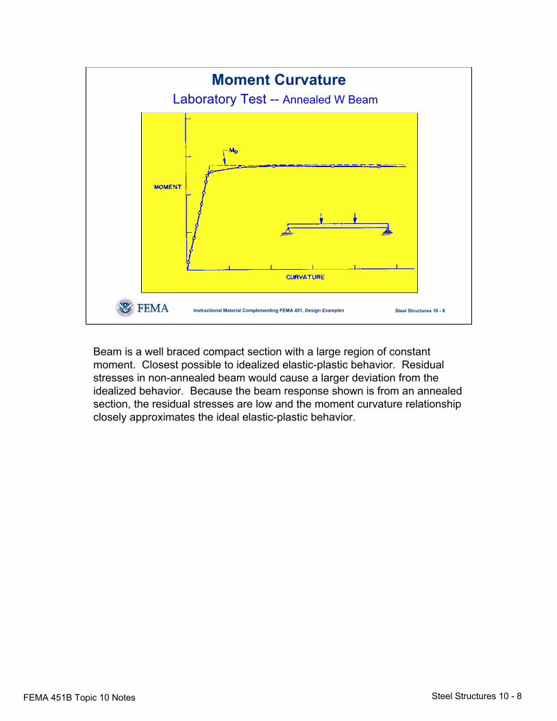
Moment CurvatureLaboratory Test -- Annealed W Beam
Beam is a well braced compact section with a large region of constant moment. Closest possible to idealized elastic-plastic behavior. Residual stresses in non-annealed beam would cause a larger deviation from the idealized behavior. Because the beam response shown is from an annealed section, the residual stresses are low and the moment curvature relationship closely approximates the ideal elastic-plastic behavior.
FEMA 451B Topic 10 Notes Steel Structures 10 - 9
Steel Structures 10 - 9Instructional Material Complementing FEMA 451, Design Examples
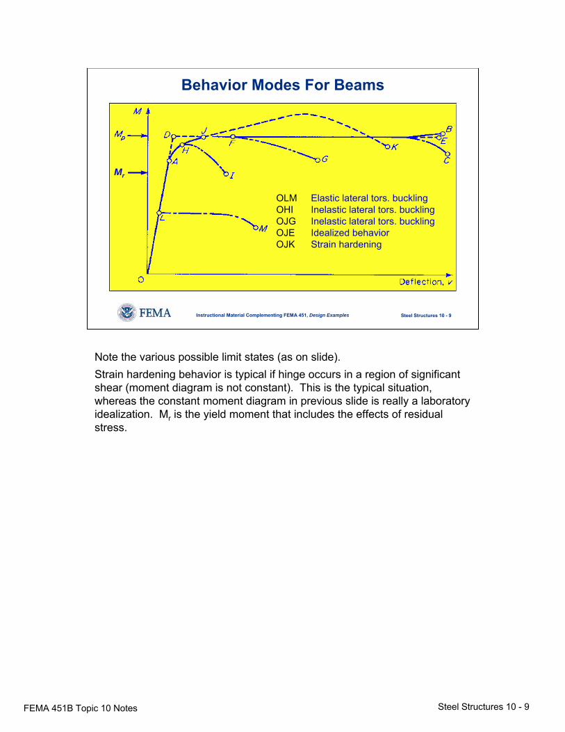
Behavior Modes For Beams
OLM Elastic lateral tors. bucklingOHI Inelastic lateral tors. bucklingOJG Inelastic lateral tors. bucklingOJE Idealized behaviorOJK Strain hardening
Mr
Note the various possible limit states (as on slide).Strain hardening behavior is typical if hinge occurs in a region of significant shear (moment diagram is not constant). This is the typical situation, whereas the constant moment diagram in previous slide is really a laboratory idealization. Mr is the yield moment that includes the effects of residual stress.
FEMA 451B Topic 10 Notes Steel Structures 10 - 10
Steel Structures 10 - 10Instructional Material Complementing FEMA 451, Design Examples
Flexural Ductility of Steel MembersPractical Limits
1 Lateral torsional bucklingBrace well
2 Local bucklingLimit width-to-thickness ratiosfor compression elements
3 FractureAvoid by proper detailing
Recall from prior lesson (inelastic behavior) that structural ductility < section ductility < material ductility. Structural ductility of steel members further limited, as noted on slide, by local and lateral buckling.
FEMA 451B Topic 10 Notes Steel Structures 10 - 11
Steel Structures 10 - 11Instructional Material Complementing FEMA 451, Design Examples
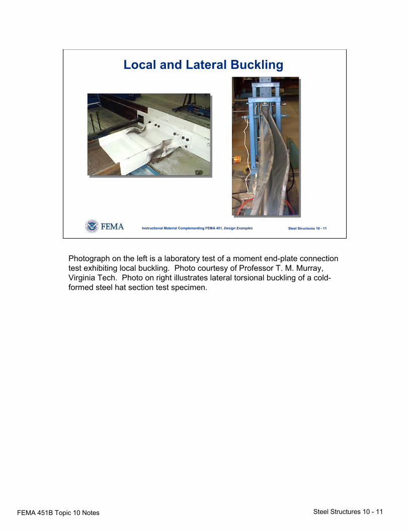
Local and Lateral Buckling
Photograph on the left is a laboratory test of a moment end-plate connection test exhibiting local buckling. Photo courtesy of Professor T. M. Murray, Virginia Tech. Photo on right illustrates lateral torsional buckling of a cold-formed steel hat section test specimen.
FEMA 451B Topic 10 Notes Steel Structures 10 - 12
Steel Structures 10 - 12Instructional Material Complementing FEMA 451, Design Examples
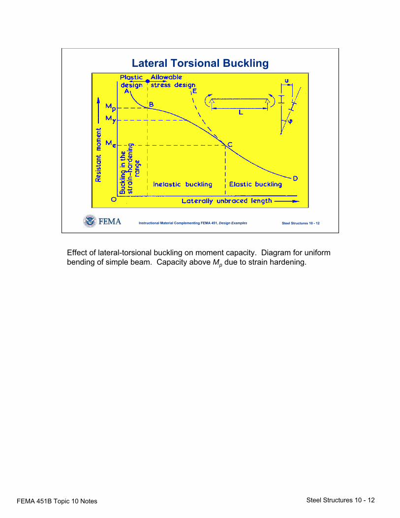
Lateral Torsional Buckling
Effect of lateral-torsional buckling on moment capacity. Diagram for uniform bending of simple beam. Capacity above Mp due to strain hardening.
FEMA 451B Topic 10 Notes Steel Structures 10 - 13
Steel Structures 10 - 13Instructional Material Complementing FEMA 451, Design Examples
Local Buckling
ycr tbEk σ
μπσ ≤
−= 22
2
)/)(1(12
b
t
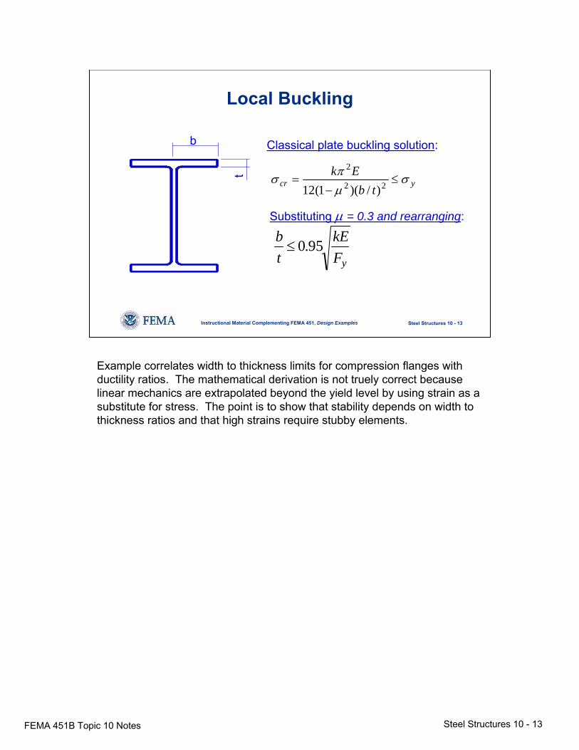
Classical plate buckling solution:
Substituting μ = 0.3 and rearranging:
yFkE
tb 95.0≤
Example correlates width to thickness limits for compression flanges with ductility ratios. The mathematical derivation is not truely correct because linear mechanics are extrapolated beyond the yield level by using strain as a substitute for stress. The point is to show that stability depends on width to thickness ratios and that high strains require stubby elements.
FEMA 451B Topic 10 Notes Steel Structures 10 - 14
Steel Structures 10 - 14Instructional Material Complementing FEMA 451, Design Examples
Local Bucklingcontinued
0.38y
b Et F≤
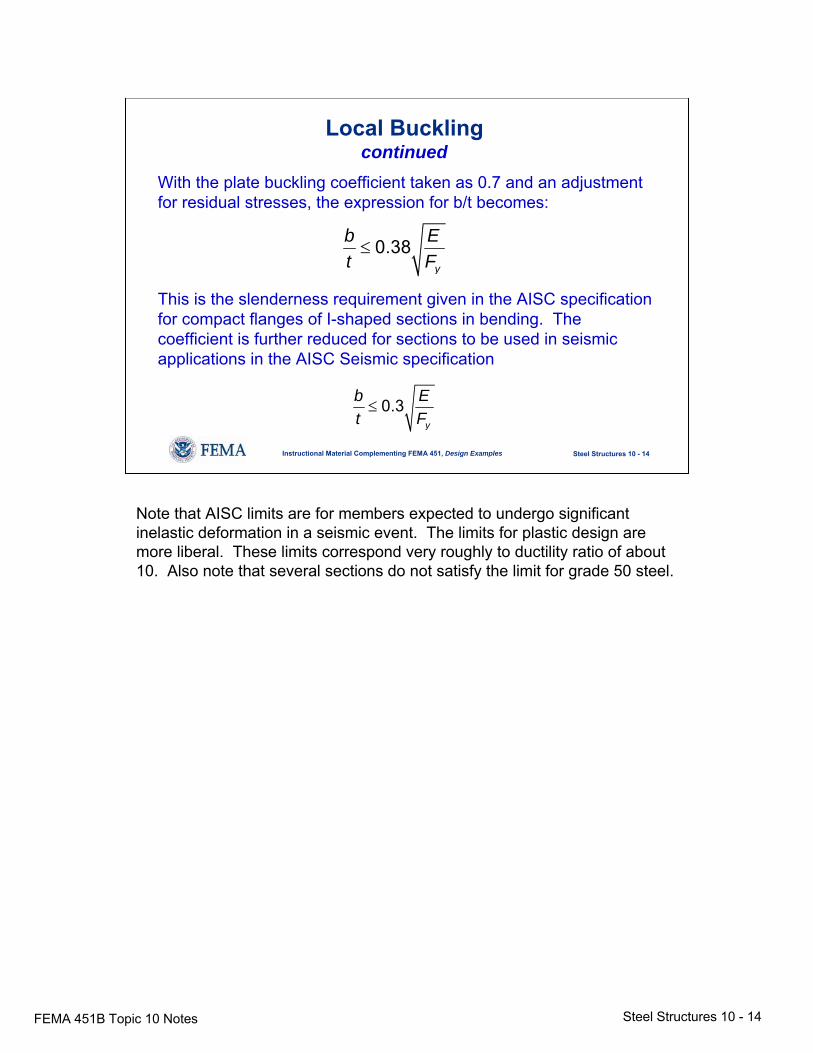
With the plate buckling coefficient taken as 0.7 and an adjustment for residual stresses, the expression for b/t becomes:
This is the slenderness requirement given in the AISC specification for compact flanges of I-shaped sections in bending. The coefficient is further reduced for sections to be used in seismic applications in the AISC Seismic specification
0.3y
b Et F≤
Note that AISC limits are for members expected to undergo significant inelastic deformation in a seismic event. The limits for plastic design are more liberal. These limits correspond very roughly to ductility ratio of about 10. Also note that several sections do not satisfy the limit for grade 50 steel.
FEMA 451B Topic 10 Notes Steel Structures 10 - 15
Steel Structures 10 - 15Instructional Material Complementing FEMA 451, Design Examples
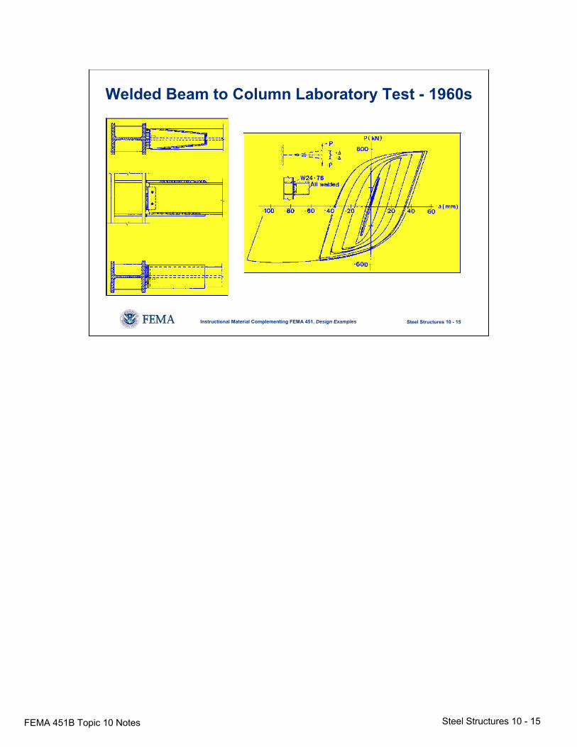
Welded Beam to Column Laboratory Test - 1960s
FEMA 451B Topic 10 Notes Steel Structures 10 - 16
Steel Structures 10 - 16Instructional Material Complementing FEMA 451, Design Examples
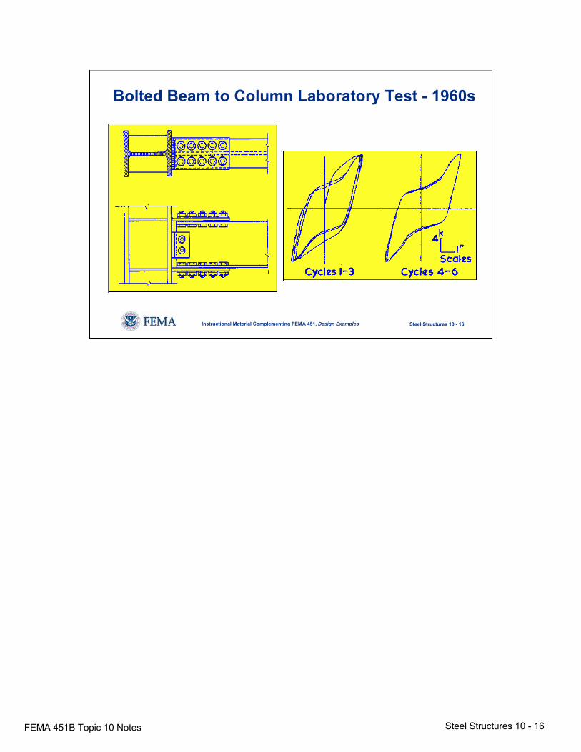
Bolted Beam to Column Laboratory Test - 1960s
FEMA 451B Topic 10 Notes Steel Structures 10 - 17
Steel Structures 10 - 17Instructional Material Complementing FEMA 451, Design Examples
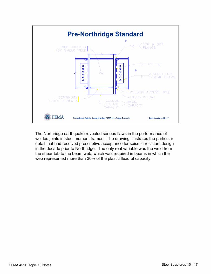
Pre-Northridge Standard
The Northridge earthquake revealed serious flaws in the performance of welded joints in steel moment frames. The drawing illustrates the particular detail that had received prescriptive acceptance for seismic-resistant design in the decade prior to Northridge. The only real variable was the weld from the shear tab to the beam web, which was required in beams in which the web represented more than 30% of the plastic flexural capacity.
FEMA 451B Topic 10 Notes Steel Structures 10 - 18
Steel Structures 10 - 18Instructional Material Complementing FEMA 451, Design Examples
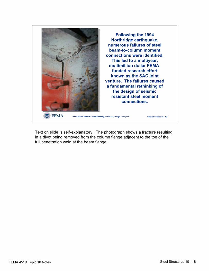
Following the 1994 Northridge earthquake,
numerous failures of steel beam-to-column moment
connections were identified. This led to a multiyear,
multimillion dollar FEMA-funded research effort known as the SAC joint
venture. The failures caused a fundamental rethinking of
the design of seismic resistant steel moment
connections.
Text on slide is self-explanatory. The photograph shows a fracture resulting in a divot being removed from the column flange adjacent to the toe of the full penetration weld at the beam flange.
FEMA 451B Topic 10 Notes Steel Structures 10 - 19
Steel Structures 10 - 19Instructional Material Complementing FEMA 451, Design Examples
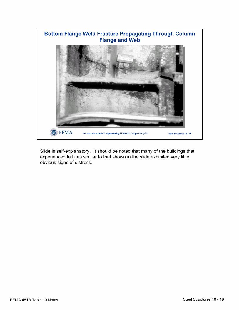
Bottom Flange Weld Fracture Propagating Through Column Flange and Web
Slide is self-explanatory. It should be noted that many of the buildings thatexperienced failures similar to that shown in the slide exhibited very little obvious signs of distress.
FEMA 451B Topic 10 Notes Steel Structures 10 - 20
Steel Structures 10 - 20Instructional Material Complementing FEMA 451, Design Examples
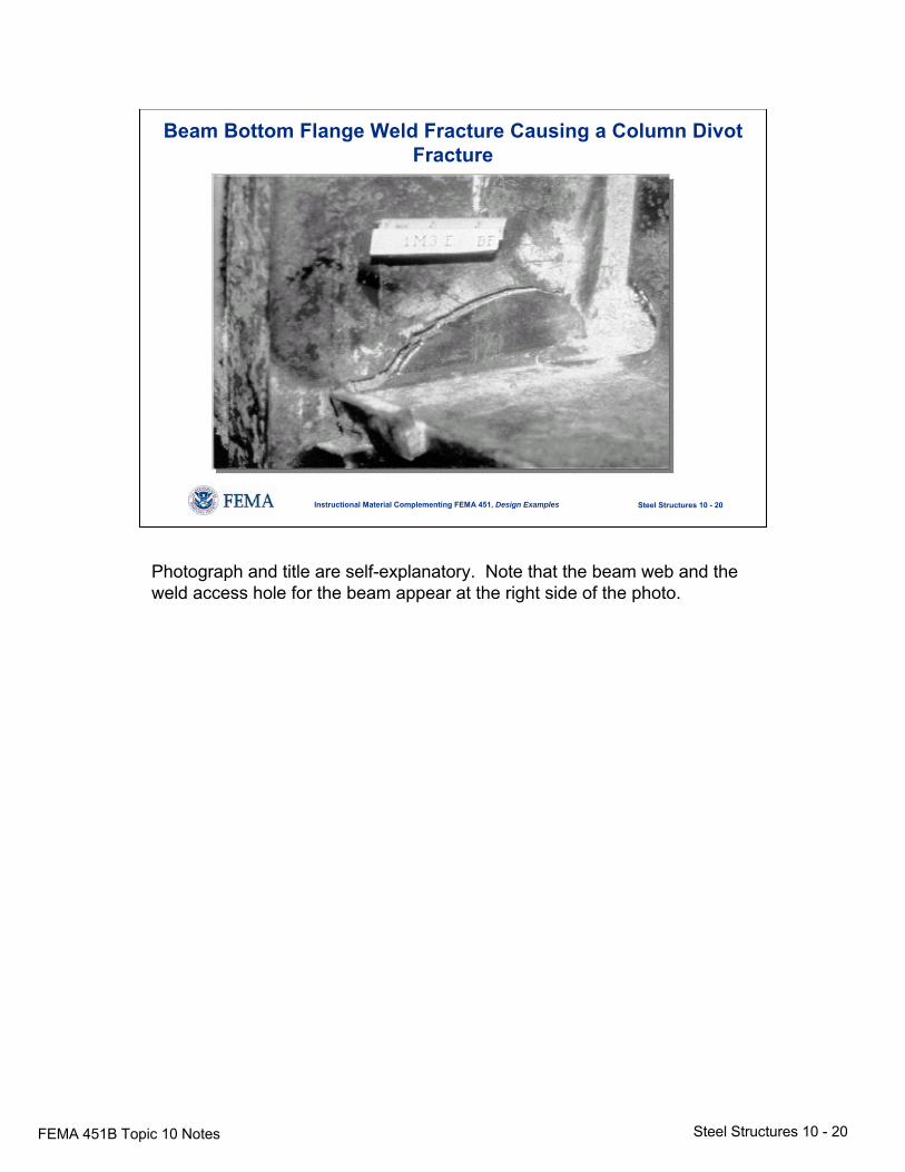
Beam Bottom Flange Weld Fracture Causing a Column Divot Fracture
Photograph and title are self-explanatory. Note that the beam web and the weld access hole for the beam appear at the right side of the photo.
FEMA 451B Topic 10 Notes Steel Structures 10 - 21
Steel Structures 10 - 21Instructional Material Complementing FEMA 451, Design Examples
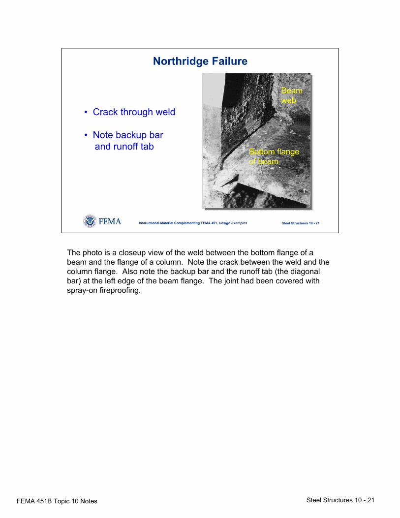
Northridge Failure
• Crack through weld
• Note backup barand runoff tab Bottom flange
of beam
Beamweb
The photo is a closeup view of the weld between the bottom flange of a beam and the flange of a column. Note the crack between the weld and the column flange. Also note the backup bar and the runoff tab (the diagonal bar) at the left edge of the beam flange. The joint had been covered with spray-on fireproofing.
FEMA 451B Topic 10 Notes Steel Structures 10 - 22
Steel Structures 10 - 22Instructional Material Complementing FEMA 451, Design Examples
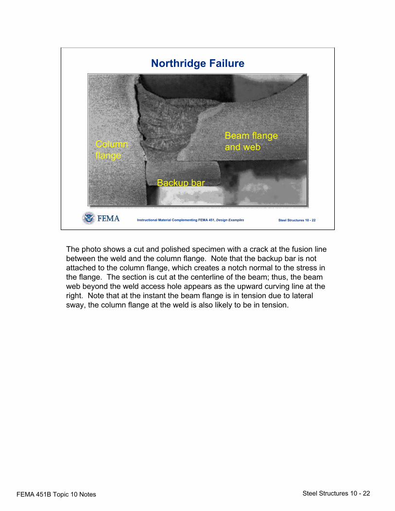
Northridge Failure
Columnflange
Backup bar
Beam flangeand web
The photo shows a cut and polished specimen with a crack at the fusion line between the weld and the column flange. Note that the backup bar is not attached to the column flange, which creates a notch normal to the stress in the flange. The section is cut at the centerline of the beam; thus, the beam web beyond the weld access hole appears as the upward curving line at the right. Note that at the instant the beam flange is in tension due to lateral sway, the column flange at the weld is also likely to be in tension.
FEMA 451B Topic 10 Notes Steel Structures 10 - 23
Steel Structures 10 - 23Instructional Material Complementing FEMA 451, Design Examples
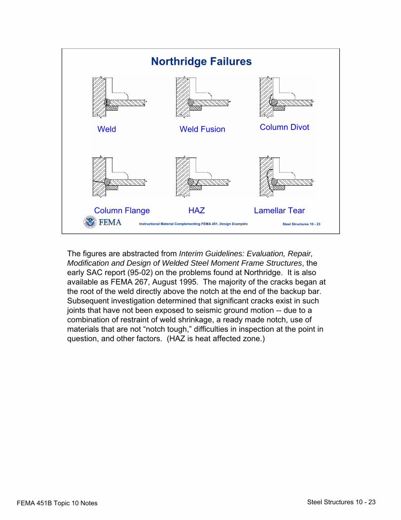
Northridge Failures
Column Flange HAZ Lamellar Tear
Weld Weld Fusion Column Divot
The figures are abstracted from Interim Guidelines: Evaluation, Repair, Modification and Design of Welded Steel Moment Frame Structures, the early SAC report (95-02) on the problems found at Northridge. It is also available as FEMA 267, August 1995. The majority of the cracks began at the root of the weld directly above the notch at the end of the backup bar. Subsequent investigation determined that significant cracks exist in such joints that have not been exposed to seismic ground motion -- due to a combination of restraint of weld shrinkage, a ready made notch, use of materials that are not “notch tough,” difficulties in inspection at the point in question, and other factors. (HAZ is heat affected zone.)
FEMA 451B Topic 10 Notes Steel Structures 10 - 24
Steel Structures 10 - 24Instructional Material Complementing FEMA 451, Design Examples
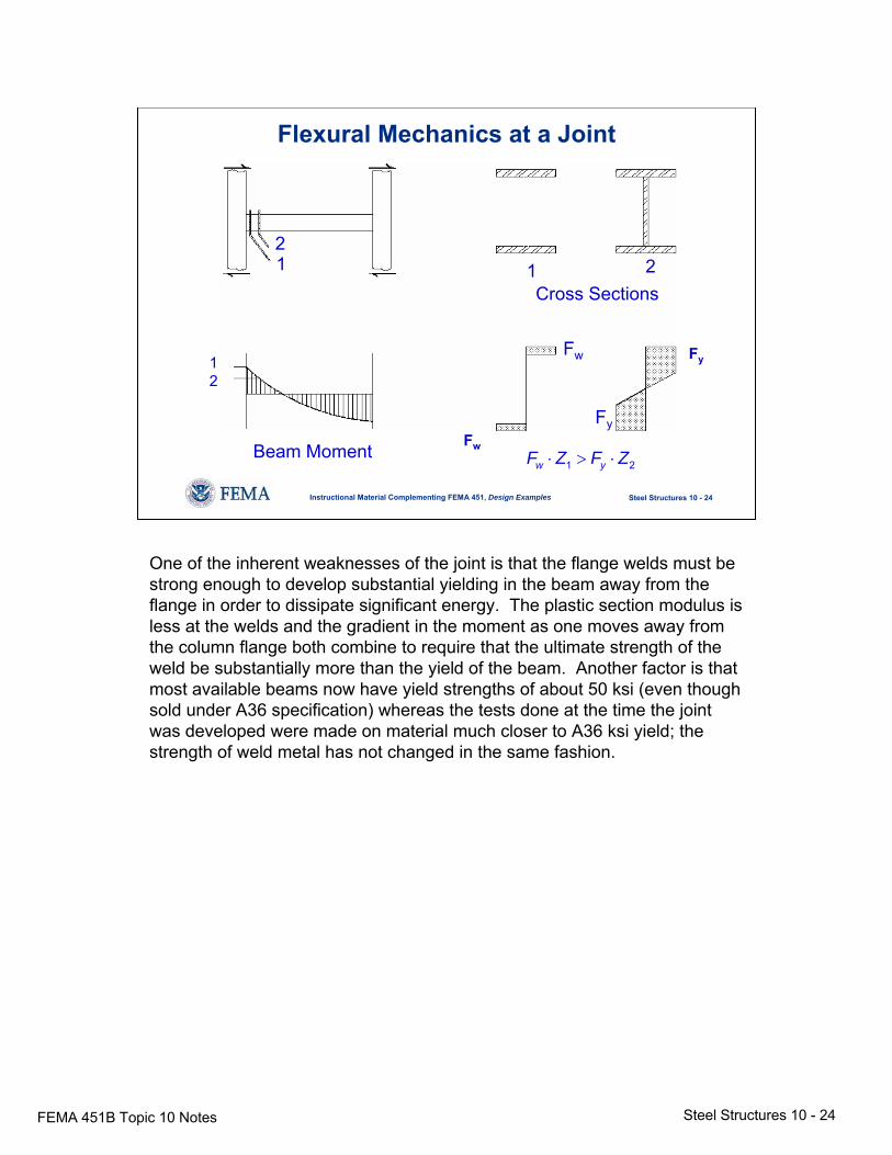
Flexural Mechanics at a Joint
12
12
Beam Moment Fw
Fy
1 2w yF Z F Z⋅ > ⋅
21 1 2
Cross Sections
Fw
Fy
One of the inherent weaknesses of the joint is that the flange welds must be strong enough to develop substantial yielding in the beam away from the flange in order to dissipate significant energy. The plastic section modulus is less at the welds and the gradient in the moment as one moves away from the column flange both combine to require that the ultimate strength of the weld be substantially more than the yield of the beam. Another factor is that most available beams now have yield strengths of about 50 ksi (even though sold under A36 specification) whereas the tests done at the time the joint was developed were made on material much closer to A36 ksi yield; the strength of weld metal has not changed in the same fashion.
FEMA 451B Topic 10 Notes Steel Structures 10 - 25
Steel Structures 10 - 25Instructional Material Complementing FEMA 451, Design Examples
Welded Steel Frames
• Northridge showed serious flaws. Problems correlated with:
- Weld material, detail concept and workmanship- Beam yield strength and size- Panel zone yield
• Repairs and new design- Move yield away from column face
(cover plates, haunches, “dog bone”)- Verify through tests
• SAC Project: FEMA Publications 350 through 354
The slide summarizes the major points learned in the first phase of the SAC project (a FEMA-funded joint venture of SEAOC, ATC, and CUREE, which is California Universities for Earthquake Engineering). The second phase of the SAC project, also funded by FEMA, was a very substantial undertaking, and much more was learned. The profession and the steel industry will continue to feel profound effects of the Northridge event for years to come. “Dog bone” is the reduction in width of beam flange at a point away from the column face in order to force first yield at that point.
FEMA 451B Topic 10 Notes Steel Structures 10 - 26
Steel Structures 10 - 26Instructional Material Complementing FEMA 451, Design Examples
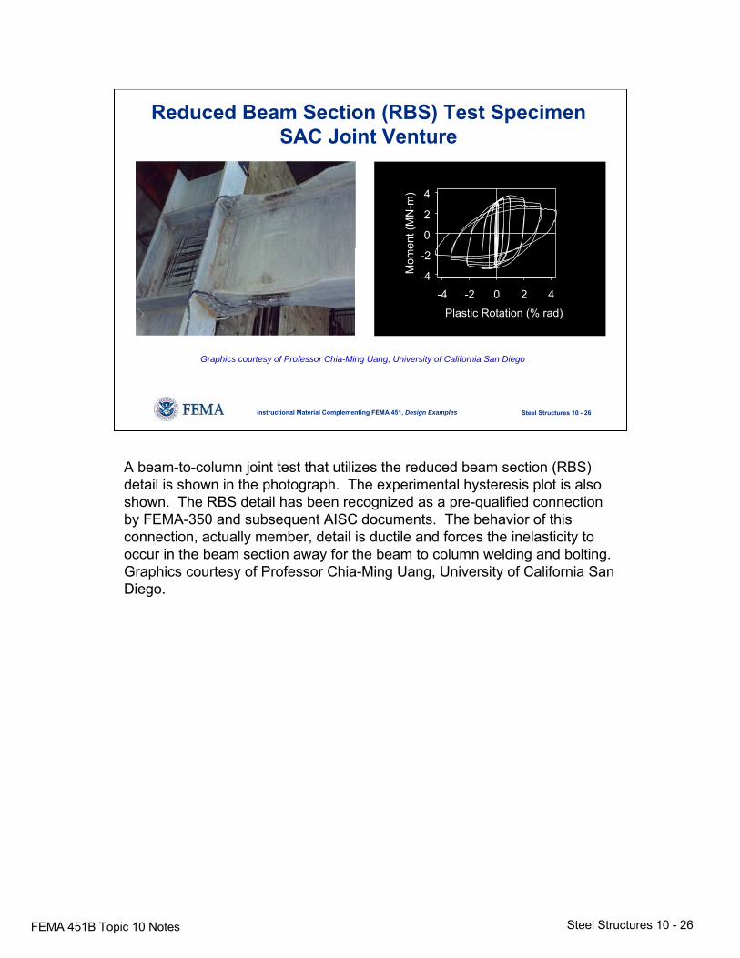
Reduced Beam Section (RBS) Test SpecimenSAC Joint Venture
Plastic Rotation (% rad)
Mom
ent (
MN
-m)
-4 -2 0 2 4-4
-2
0
2
4
Graphics courtesy of Professor Chia-Ming Uang, University of California San Diego
A beam-to-column joint test that utilizes the reduced beam section (RBS) detail is shown in the photograph. The experimental hysteresis plot is also shown. The RBS detail has been recognized as a pre-qualified connection by FEMA-350 and subsequent AISC documents. The behavior of this connection, actually member, detail is ductile and forces the inelasticity to occur in the beam section away for the beam to column welding and bolting. Graphics courtesy of Professor Chia-Ming Uang, University of California San Diego.
FEMA 451B Topic 10 Notes Steel Structures 10 - 27
Steel Structures 10 - 27Instructional Material Complementing FEMA 451, Design Examples
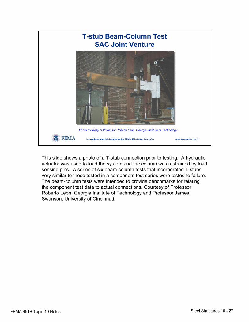
T-stub Beam-Column TestSAC Joint Venture
Photo courtesy of Professor Roberto Leon, Georgia Institute of Technology
This slide shows a photo of a T-stub connection prior to testing. A hydraulic actuator was used to load the system and the column was restrained by load sensing pins. A series of six beam-column tests that incorporated T-stubs very similar to those tested in a component test series were tested to failure. The beam-column tests were intended to provide benchmarks for relating the component test data to actual connections. Courtesy of Professor Roberto Leon, Georgia Institute of Technology and Professor James Swanson, University of Cincinnati.
FEMA 451B Topic 10 Notes Steel Structures 10 - 28
Steel Structures 10 - 28Instructional Material Complementing FEMA 451, Design Examples
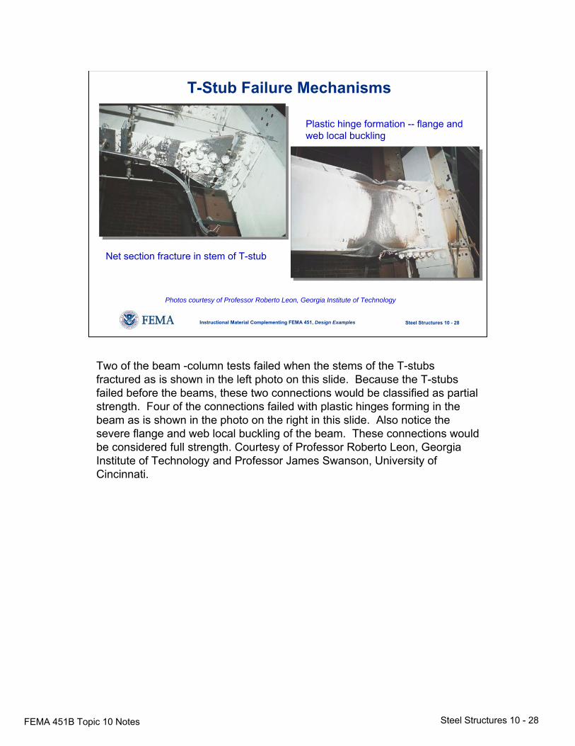
T-Stub Failure Mechanisms
Net section fracture in stem of T-stub
Plastic hinge formation -- flange and web local buckling
Photos courtesy of Professor Roberto Leon, Georgia Institute of Technology
Two of the beam -column tests failed when the stems of the T-stubs fractured as is shown in the left photo on this slide. Because the T-stubs failed before the beams, these two connections would be classified as partial strength. Four of the connections failed with plastic hinges forming in the beam as is shown in the photo on the right in this slide. Also notice the severe flange and web local buckling of the beam. These connections would be considered full strength. Courtesy of Professor Roberto Leon, Georgia Institute of Technology and Professor James Swanson, University of Cincinnati.
FEMA 451B Topic 10 Notes Steel Structures 10 - 29
Steel Structures 10 - 29Instructional Material Complementing FEMA 451, Design Examples
Rotation (rad)-0.06 -0.04 -0.02 0.00 0.02 0.04 0.06
Mom
ent (
k-in
)
-7000-6000-5000-4000-3000-2000-1000
01000200030004000500060007000
Mom
ent (
kN-m
)
-700-600-500-400-300-200-1000100200300400500600700
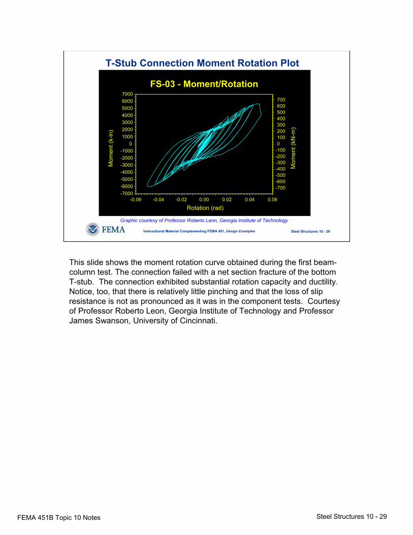
FS-03 - Moment/Rotation
T-Stub Connection Moment Rotation Plot
Graphic courtesy of Professor Roberto Leon, Georgia Institute of Technology
This slide shows the moment rotation curve obtained during the first beam-column test. The connection failed with a net section fracture of the bottom T-stub. The connection exhibited substantial rotation capacity and ductility. Notice, too, that there is relatively little pinching and that the loss of slip resistance is not as pronounced as it was in the component tests. Courtesy of Professor Roberto Leon, Georgia Institute of Technology and Professor James Swanson, University of Cincinnati.
FEMA 451B Topic 10 Notes Steel Structures 10 - 30
Steel Structures 10 - 30Instructional Material Complementing FEMA 451, Design Examples
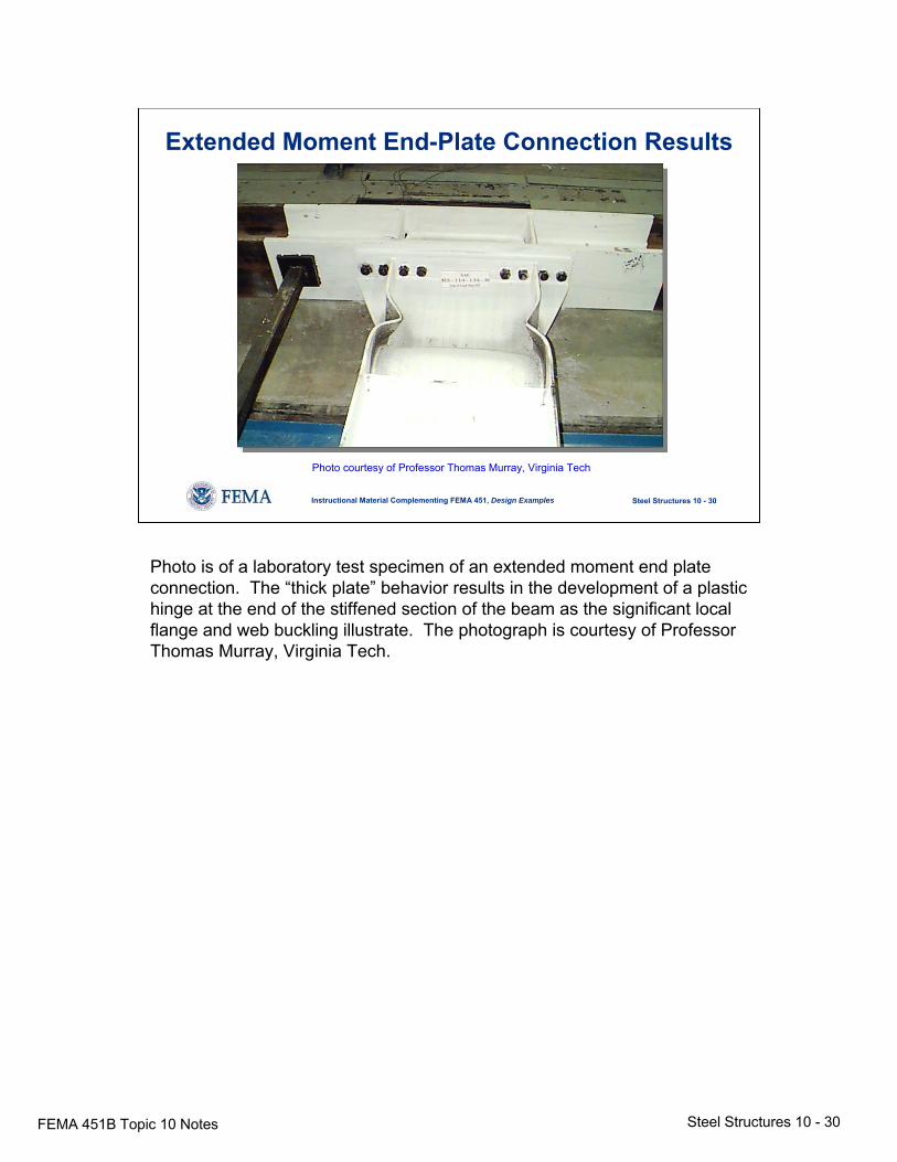
Extended Moment End-Plate Connection Results
Photo courtesy of Professor Thomas Murray, Virginia Tech
Photo is of a laboratory test specimen of an extended moment end plate connection. The “thick plate” behavior results in the development of a plastic hinge at the end of the stiffened section of the beam as the significant local flange and web buckling illustrate. The photograph is courtesy of Professor Thomas Murray, Virginia Tech.
FEMA 451B Topic 10 Notes Steel Structures 10 - 31
Steel Structures 10 - 31Instructional Material Complementing FEMA 451, Design Examples
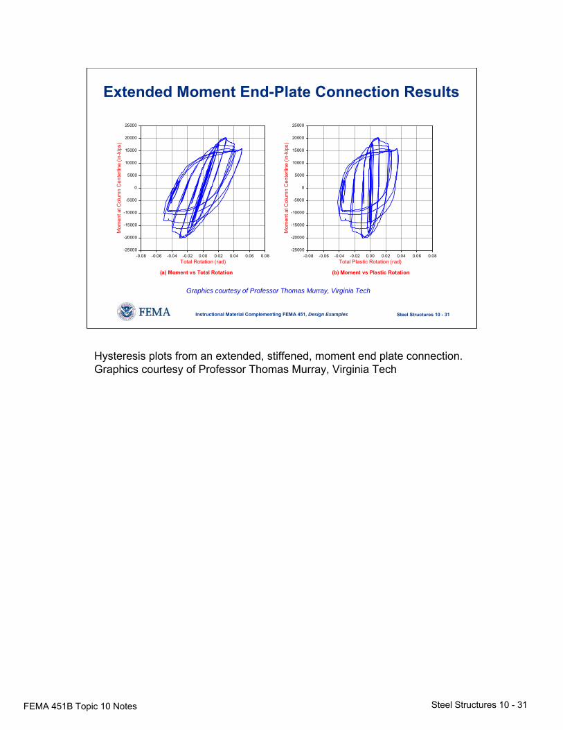
Extended Moment End-Plate Connection Results
Total Plastic Rotation (rad)-0.08 -0.06 -0.04 -0.02 0.00 0.02 0.04 0.06 0.08
Mom
ent a
t Col
umn
Cen
terli
ne (i
n-ki
ps)
-25000
-20000
-15000
-10000
-5000
0
5000
10000
15000
20000
25000
(b) Moment vs Plastic Rotation(a) Moment vs Total Rotation
Total Rotation (rad)-0.08 -0.06 -0.04 -0.02 0.00 0.02 0.04 0.06 0.08
Mom
ent a
t Col
umn
Cen
terli
ne (i
n-ki
ps)
-25000
-20000
-15000
-10000
-5000
0
5000
10000
15000
20000
25000
Graphics courtesy of Professor Thomas Murray, Virginia Tech
Hysteresis plots from an extended, stiffened, moment end plate connection.Graphics courtesy of Professor Thomas Murray, Virginia Tech
FEMA 451B Topic 10 Notes Steel Structures 10 - 32
Steel Structures 10 - 32Instructional Material Complementing FEMA 451, Design Examples
Ductility of Steel Frame JointsLimits
Welded Joints- Brittle fracture of weld- Lamellar tearing of base metal- Joint design, testing, and inspection
Bolted Joints- Fracture at net cross-section- Excessive slip
Joint Too Weak For Member- Shear in joint panel
Text on slide is self-explanatory. Other failures not on slide were due to crushing or buckling of column web, distortion of column flange, or panel zone shear yielding or buckling.
FEMA 451B Topic 10 Notes Steel Structures 10 - 33
Steel Structures 10 - 33Instructional Material Complementing FEMA 451, Design Examples
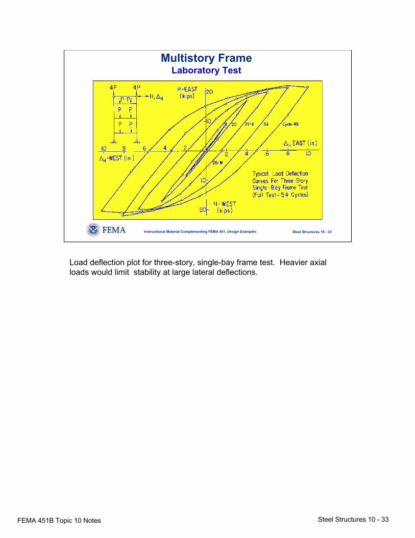
Multistory FrameLaboratory Test
Load deflection plot for three-story, single-bay frame test. Heavier axial loads would limit stability at large lateral deflections.
FEMA 451B Topic 10 Notes Steel Structures 10 - 34
Steel Structures 10 - 34Instructional Material Complementing FEMA 451, Design Examples
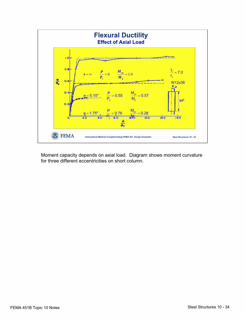
Flexural DuctilityEffect of Axial Load
0.10 ==∞=p
pc
y MM
PPe
57.0MM
55.0PP"10.5e
p
pc
y
===
28.0MM
76.0PP"75.1e
p
pc
y
===
0.7rLx
=
W12x36
Moment capacity depends on axial load. Diagram shows moment curvature for three different eccentricities on short column.
FEMA 451B Topic 10 Notes Steel Structures 10 - 35
Steel Structures 10 - 35Instructional Material Complementing FEMA 451, Design Examples
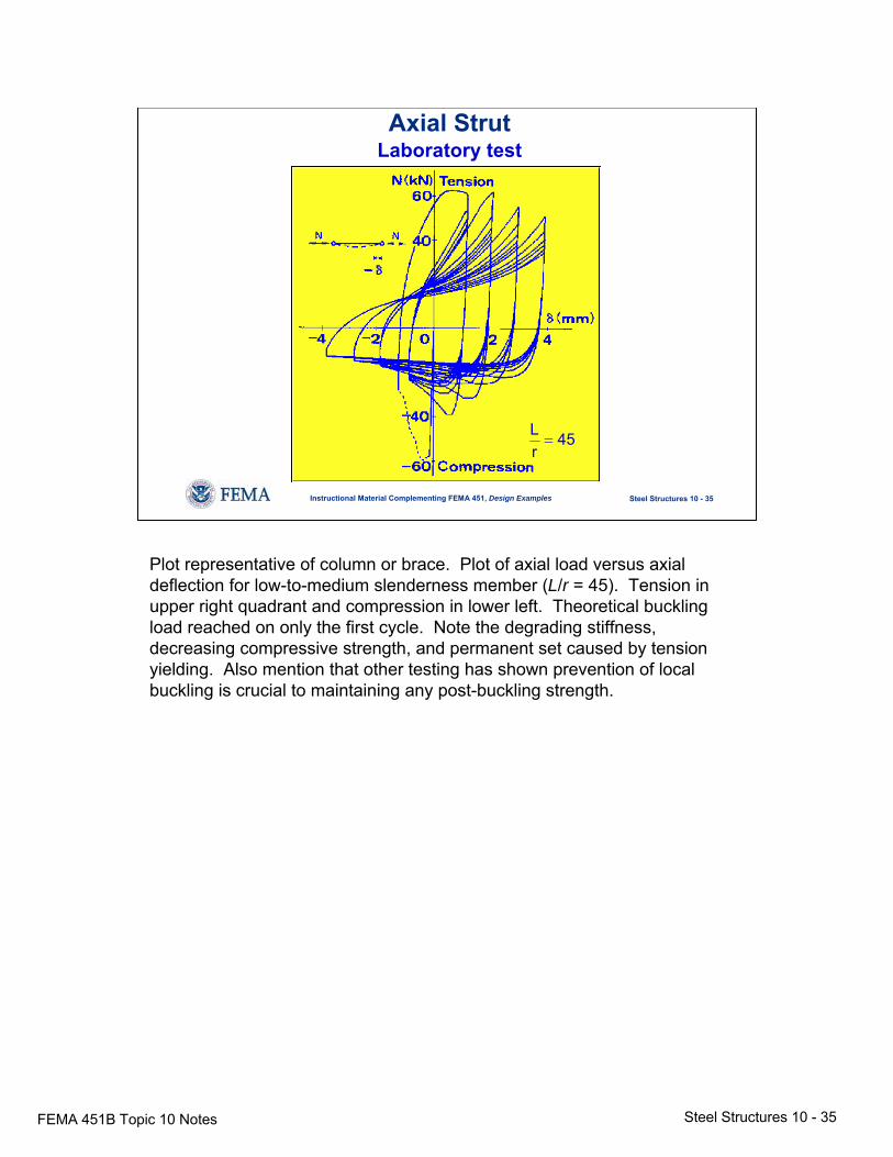
Axial StrutLaboratory test
45rL=
Plot representative of column or brace. Plot of axial load versus axial deflection for low-to-medium slenderness member (L/r = 45). Tension in upper right quadrant and compression in lower left. Theoretical buckling load reached on only the first cycle. Note the degrading stiffness, decreasing compressive strength, and permanent set caused by tension yielding. Also mention that other testing has shown prevention of local buckling is crucial to maintaining any post-buckling strength.
FEMA 451B Topic 10 Notes Steel Structures 10 - 36
Steel Structures 10 - 36Instructional Material Complementing FEMA 451, Design Examples
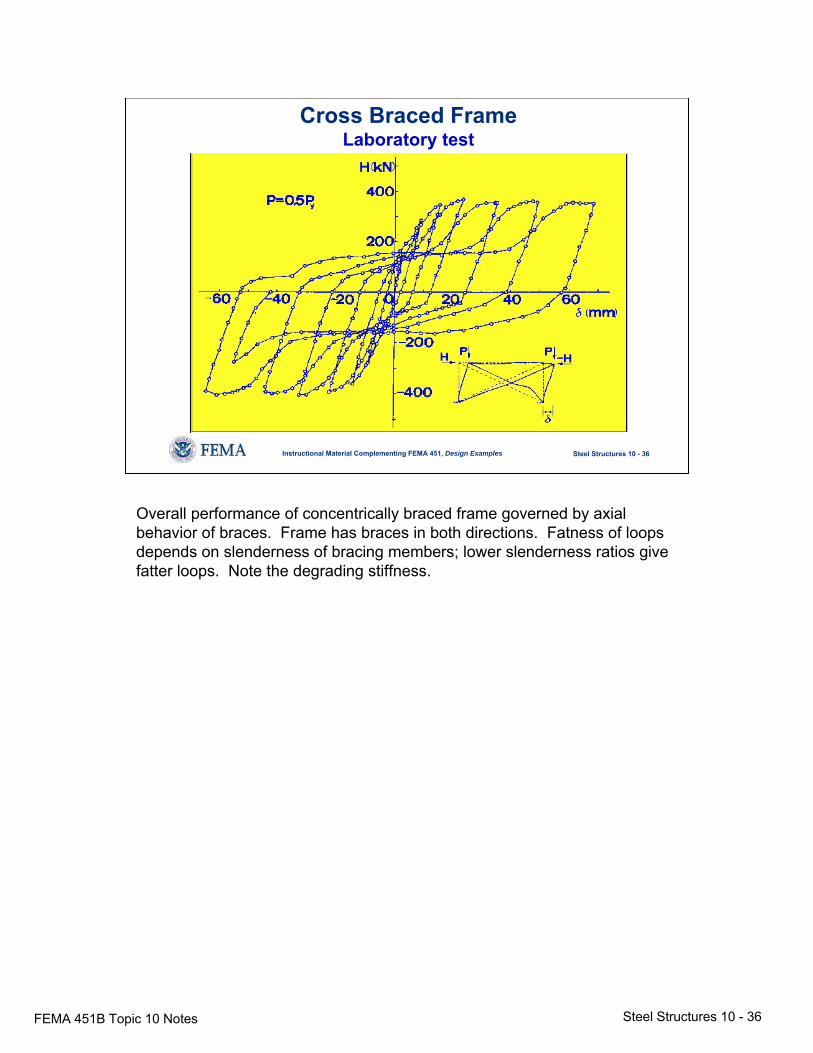
Cross Braced FrameLaboratory test
Overall performance of concentrically braced frame governed by axial behavior of braces. Frame has braces in both directions. Fatness of loops depends on slenderness of bracing members; lower slenderness ratios give fatter loops. Note the degrading stiffness.
FEMA 451B Topic 10 Notes Steel Structures 10 - 37
Steel Structures 10 - 37Instructional Material Complementing FEMA 451, Design Examples
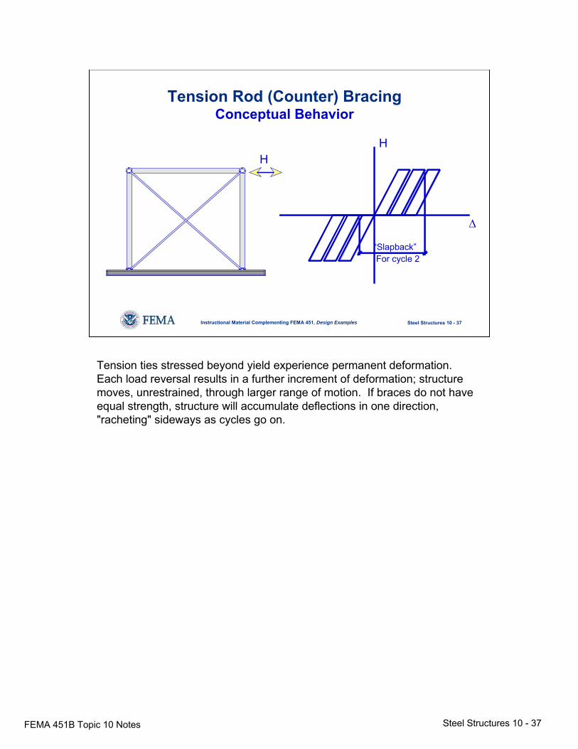
Tension Rod (Counter) BracingConceptual Behavior
H
Δ
“Slapback”For cycle 2
H
Tension ties stressed beyond yield experience permanent deformation. Each load reversal results in a further increment of deformation; structure moves, unrestrained, through larger range of motion. If braces do not have equal strength, structure will accumulate deflections in one direction, "racheting" sideways as cycles go on.
FEMA 451B Topic 10 Notes Steel Structures 10 - 38
Steel Structures 10 - 38Instructional Material Complementing FEMA 451, Design Examples
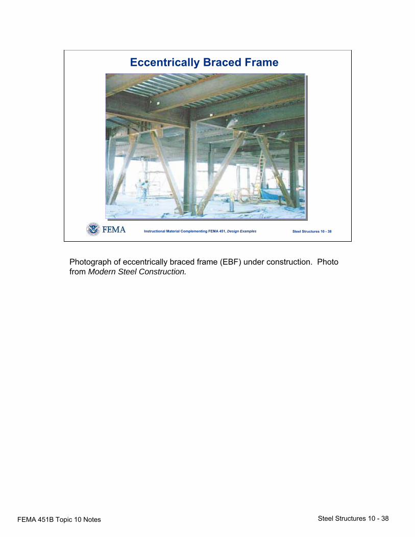
Eccentrically Braced Frame
Photograph of eccentrically braced frame (EBF) under construction. Photo from Modern Steel Construction.
FEMA 451B Topic 10 Notes Steel Structures 10 - 39
Steel Structures 10 - 39Instructional Material Complementing FEMA 451, Design Examples
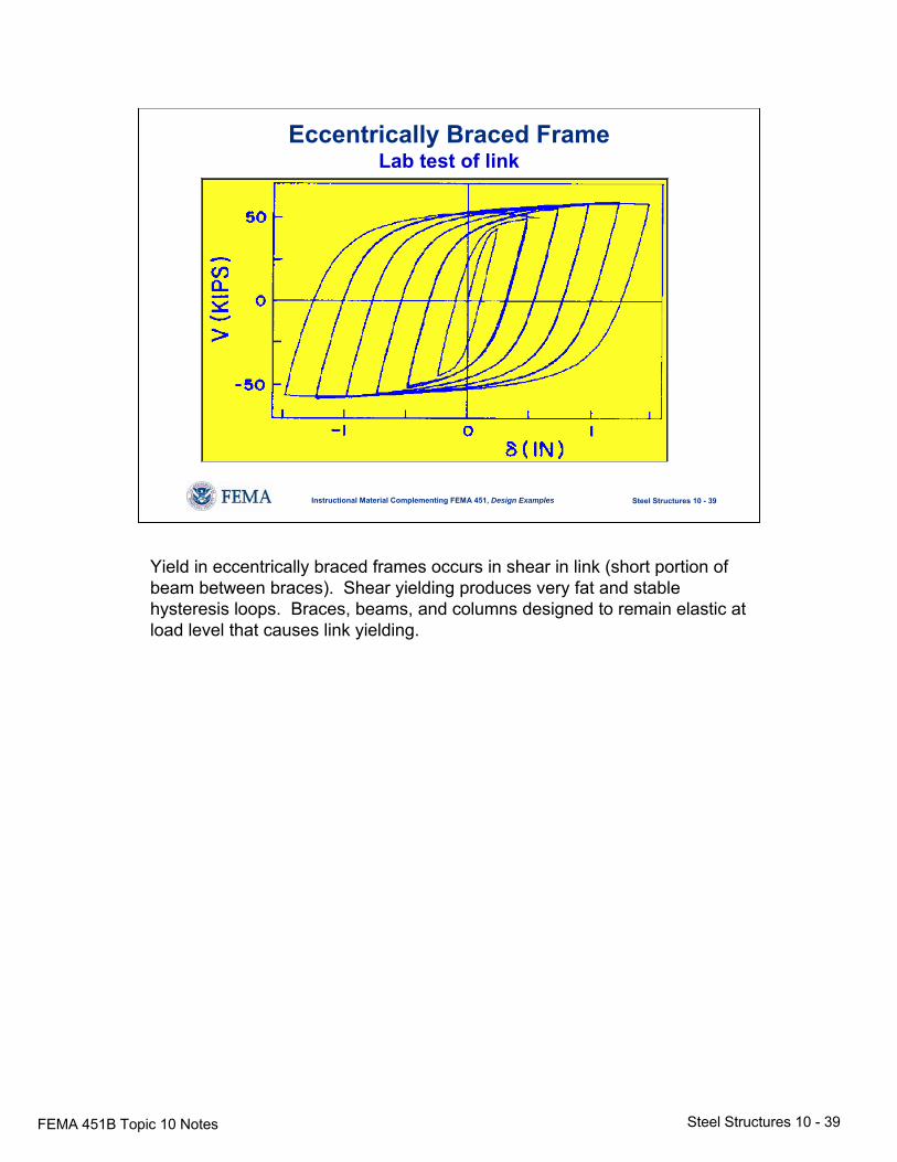
Eccentrically Braced FrameLab test of link
Yield in eccentrically braced frames occurs in shear in link (short portion of beam between braces). Shear yielding produces very fat and stable hysteresis loops. Braces, beams, and columns designed to remain elastic at load level that causes link yielding.
FEMA 451B Topic 10 Notes Steel Structures 10 - 40
Steel Structures 10 - 40Instructional Material Complementing FEMA 451, Design Examples
Steel Behavior• Ductility
- Material inherently ductile- Ductility of structure < ductility of material
• Damping- Welded structures have low damping- More damping in bolted structures dueto slip at connections
- Primary energy absorption is yielding ofmembers
Steels used in construction are typically extremely ductile materials. Ductility of the steel structure or system is less (sometimes many times less) than the ductility of the material because only a portion of material in the system will actually experience yielding. Damping is typically not high in steel structures, especially in welded structures. Bolted structures exhibit a higher degree of damping due to slip at connections. Unlike structures of other materials, the primary energy absorption mode in steel structures is yielding of members, usually in bending but sometimes in shear, axial tension, or compression.
FEMA 451B Topic 10 Notes Steel Structures 10 - 41
Steel Structures 10 - 41Instructional Material Complementing FEMA 451, Design Examples
Steel Behavior• Buckling
- Most common steel failure under earthquake loads- Usually not ductile- Local buckling of portion of member- Global buckling of member- Global buckling of structure
• Fracture- Nonductile failure mode under earthquake loads- Heavy welded connections susceptible
Typical failure in steel structure subjected to earthquake is buckling, either global buckling of member, local buckling of portion of member, or global buckling of entire structure. Another potential weakness in steel structures is susceptibility to fracture; primarily a concern in heavy welded connections, members with notches, and in cold environments. Northridge earthquake has created substantially more concern about fracture.
FEMA 451B Topic 10 Notes Steel Structures 10 - 42
Steel Structures 10 - 42Instructional Material Complementing FEMA 451, Design Examples
NEHRP Recommended ProvisionsSteel Design
• Context in NEHRP Recommended Provisions
• Steel behavior
• Reference standards and design strength
Table of contents: Reference standards and design strength. The Provisionsreferences commonly accepted codes for each material and indicates how requirements in those standards must be modified for use with the NEHRP Recommended Provisions seismic design procedure. Special additional provisions are also included in each materials chapter.
FEMA 451B Topic 10 Notes Steel Structures 10 - 43
Steel Structures 10 - 43Instructional Material Complementing FEMA 451, Design Examples
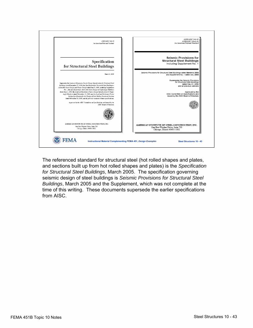
The referenced standard for structural steel (hot rolled shapes and plates, and sections built up from hot rolled shapes and plates) is the Specification for Structural Steel Buildings, March 2005. The specification governing seismic design of steel buildings is Seismic Provisions for Structural Steel Buildings, March 2005 and the Supplement, which was not complete at the time of this writing. These documents supersede the earlier specifications from AISC.
FEMA 451B Topic 10 Notes Steel Structures 10 - 44
Steel Structures 10 - 44Instructional Material Complementing FEMA 451, Design Examples
Using Reference StandardsStructural Steel
Both the AISC LRFD and ASD methodologies are presented in a unified format in both the Specification for Structural Steel Buildings and the Seismic Provisions for Structural Steel Buildings.
Slide is self-explanatory.
FEMA 451B Topic 10 Notes Steel Structures 10 - 45
Steel Structures 10 - 45Instructional Material Complementing FEMA 451, Design Examples
Reference standard for cold formed steel is the AISI North AmericanSpecification for the Design of Cold-formed Steel Structural Members (shown on slide). It includes both ASD and LRFD. ASCE 8-90 is a similar standard (LRFD only) for cold-formed stainless steel. The Provisions adjusts the load factor to be compatible.
FEMA 451B Topic 10 Notes Steel Structures 10 - 46
Steel Structures 10 - 46Instructional Material Complementing FEMA 451, Design Examples
Other Steel MembersSteel Joist Institute
Standard Specifications, 2002
Steel CablesASCE 19-1996
Steel Deck InstituteDiaphragm Design Manual, 3rd Ed., 2005
For design of other specialized steel members, the Provisions refers user to standards published by Steel Joist Institute and the ASCE 19 standard for cables. The Provisions indicates how SJI allowables should be increased to maximum strengths for use in seismic resistant design and give guidelines for modification of cable allowables. Note the Steel Deck Institute’s Diaphragm Design Manual is no longer referenced in the Provisions although it is a good source (do not use the 2.75 “factor of safety”). There are also other sources for steel deck diaphragms.
FEMA 451B Topic 10 Notes Steel Structures 10 - 47
Steel Structures 10 - 47Instructional Material Complementing FEMA 451, Design Examples
NEHRP Recommended ProvisionsSteel Design
• Context in NEHRP Recommended Provisions
• Steel behavior
• Reference standards and design strength
• Moment resisting frames
Table of contents: Moment resisting frames.
FEMA 451B Topic 10 Notes Steel Structures 10 - 48
Steel Structures 10 - 48Instructional Material Complementing FEMA 451, Design Examples
Steel Moment Frame Joints
Frame Test θi Details
Special Req’d 0.04 Many
Intermediate Req’d 0.02 Moderate
Ordinary Allowed NA Few
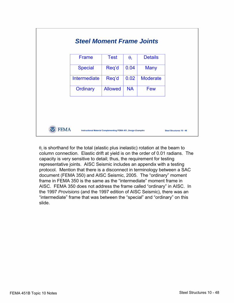
θi is shorthand for the total (elastic plus inelastic) rotation at the beam to column connection. Elastic drift at yield is on the order of 0.01 radians. The capacity is very sensitive to detail; thus, the requirement for testing representative joints. AISC Seismic includes an appendix with a testing protocol. Mention that there is a disconnect in terminology between a SAC document (FEMA 350) and AISC Seismic, 2005. The “ordinary” moment frame in FEMA 350 is the same as the “intermediate” moment frame in AISC. FEMA 350 does not address the frame called “ordinary” in AISC. In the 1997 Provisions (and the 1997 edition of AISC Seismic), there was an “intermediate” frame that was between the “special” and “ordinary” on this slide.
FEMA 451B Topic 10 Notes Steel Structures 10 - 49
Steel Structures 10 - 49Instructional Material Complementing FEMA 451, Design Examples
Steel Moment Frame Joints
u pa bM M
b+
≈ ⋅
*y y yF R F= ⋅
* *1 1.7u y yf
a bF F Z Fb A d+
≈ ⋅ ⋅ ≈
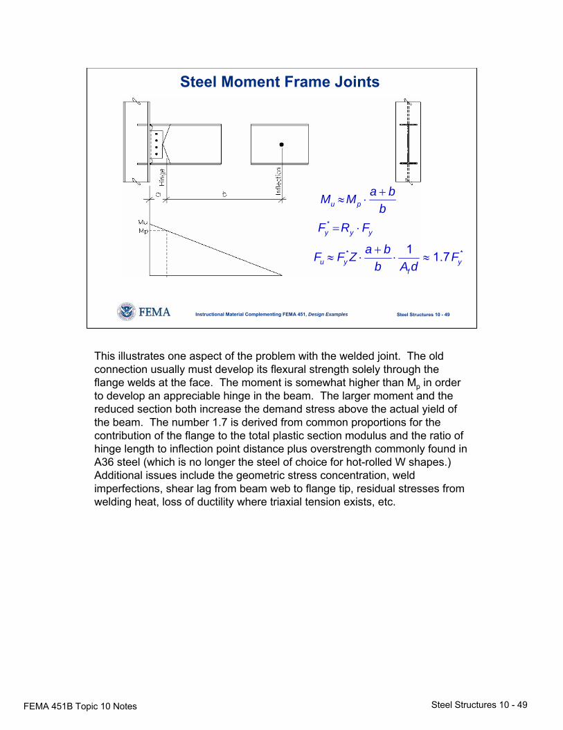
This illustrates one aspect of the problem with the welded joint. The old connection usually must develop its flexural strength solely through the flange welds at the face. The moment is somewhat higher than Mp in order to develop an appreciable hinge in the beam. The larger moment and the reduced section both increase the demand stress above the actual yield of the beam. The number 1.7 is derived from common proportions for the contribution of the flange to the total plastic section modulus and the ratio of hinge length to inflection point distance plus overstrength commonly found in A36 steel (which is no longer the steel of choice for hot-rolled W shapes.) Additional issues include the geometric stress concentration, weld imperfections, shear lag from beam web to flange tip, residual stresses from welding heat, loss of ductility where triaxial tension exists, etc.
FEMA 451B Topic 10 Notes Steel Structures 10 - 50
Steel Structures 10 - 50Instructional Material Complementing FEMA 451, Design Examples
Panel Zones
Special and intermediate moment frame:
• Shear strength demand:
Basic load combination or φRyMp of beams• Shear capacity equation
• Thickness (for buckling)
• Use of doubler plates
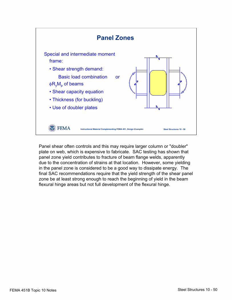
Panel shear often controls and this may require larger column or "doubler" plate on web, which is expensive to fabricate. SAC testing has shown that panel zone yield contributes to fracture of beam flange welds, apparently due to the concentration of strains at that location. However, some yielding in the panel zone is considered to be a good way to dissipate energy. The final SAC recommendations require that the yield strength of the shear panel zone be at least strong enough to reach the beginning of yield in the beam flexural hinge areas but not full development of the flexural hinge.
FEMA 451B Topic 10 Notes Steel Structures 10 - 51
Steel Structures 10 - 51Instructional Material Complementing FEMA 451, Design Examples
Steel Moment Frames• Beam shear: 1.1RyMp + gravity
• Beam local buckling - Smaller b/t than LRFD for plastic design
• Continuity plates in joint per tests
• Strong column - weak beam rule- Prevent column yield except in panel zone- Exceptions: Low axial load, strong stories, top
story,and non-SRS columns
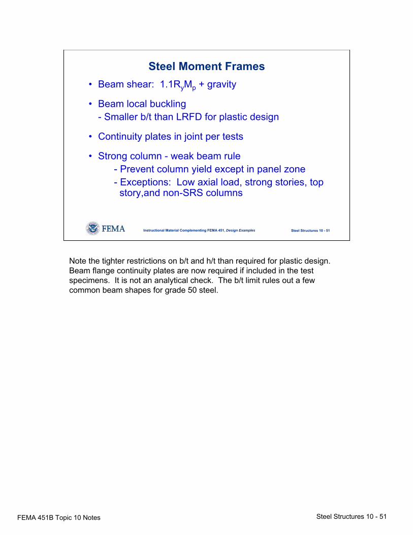
Note the tighter restrictions on b/t and h/t than required for plastic design. Beam flange continuity plates are now required if included in the test specimens. It is not an analytical check. The b/t limit rules out a few common beam shapes for grade 50 steel.
FEMA 451B Topic 10 Notes Steel Structures 10 - 52
Steel Structures 10 - 52Instructional Material Complementing FEMA 451, Design Examples
Steel Moment Frames
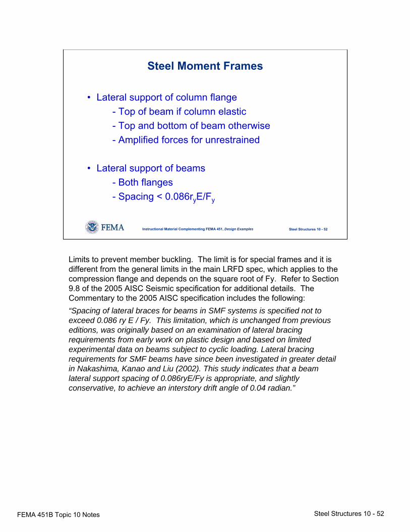
• Lateral support of column flange- Top of beam if column elastic- Top and bottom of beam otherwise- Amplified forces for unrestrained
• Lateral support of beams- Both flanges- Spacing < 0.086ryE/Fy
Limits to prevent member buckling. The limit is for special frames and it is different from the general limits in the main LRFD spec, which applies to the compression flange and depends on the square root of Fy. Refer to Section 9.8 of the 2005 AISC Seismic specification for additional details. The Commentary to the 2005 AISC specification includes the following: “Spacing of lateral braces for beams in SMF systems is specified not to exceed 0.086 ry E / Fy. This limitation, which is unchanged from previous editions, was originally based on an examination of lateral bracing requirements from early work on plastic design and based on limited experimental data on beams subject to cyclic loading. Lateral bracing requirements for SMF beams have since been investigated in greater detail in Nakashima, Kanao and Liu (2002). This study indicates that a beam lateral support spacing of 0.086ryE/Fy is appropriate, and slightly conservative, to achieve an interstory drift angle of 0.04 radian.”
FEMA 451B Topic 10 Notes Steel Structures 10 - 53
Steel Structures 10 - 53Instructional Material Complementing FEMA 451, Design Examples
Prequalified Connections
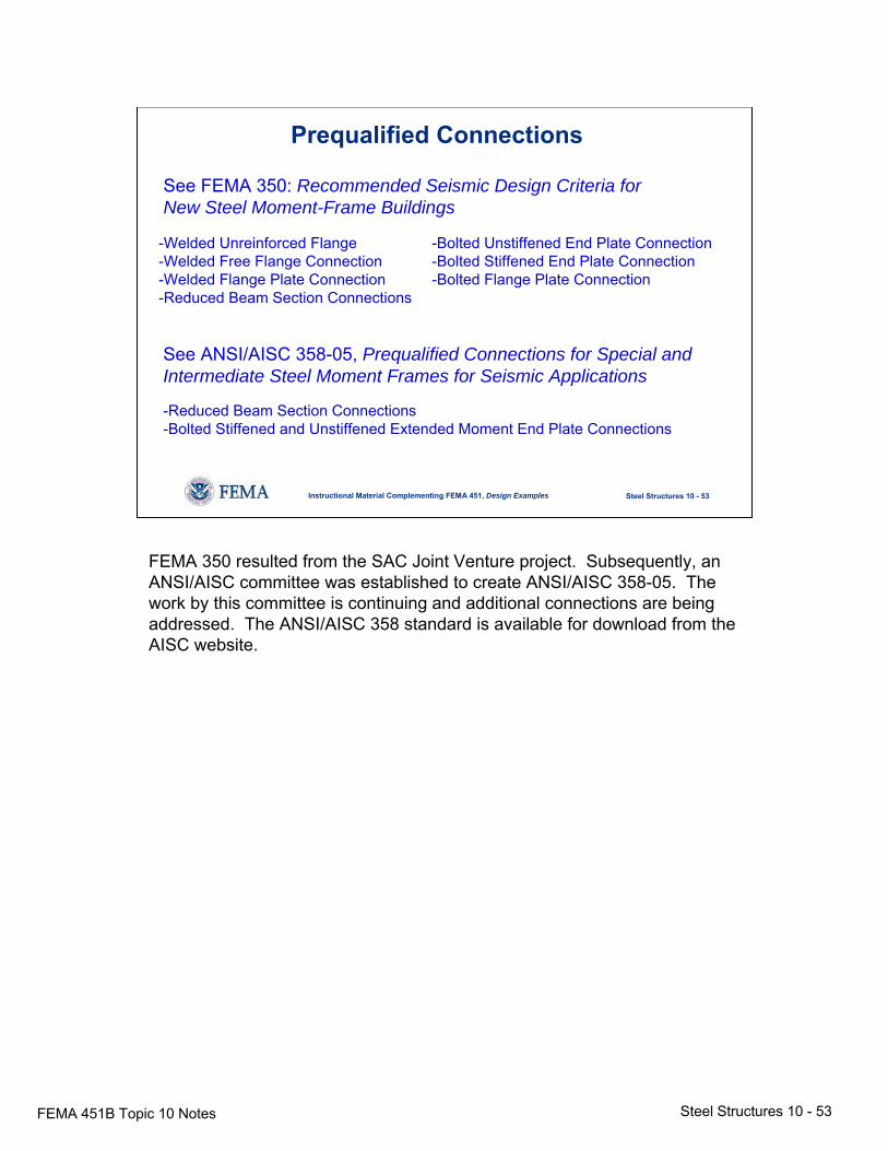
See FEMA 350: Recommended Seismic Design Criteria forNew Steel Moment-Frame Buildings
-Welded Unreinforced Flange -Bolted Unstiffened End Plate Connection-Welded Free Flange Connection -Bolted Stiffened End Plate Connection-Welded Flange Plate Connection -Bolted Flange Plate Connection-Reduced Beam Section Connections
See ANSI/AISC 358-05, Prequalified Connections for Special and Intermediate Steel Moment Frames for Seismic Applications
-Reduced Beam Section Connections-Bolted Stiffened and Unstiffened Extended Moment End Plate Connections
FEMA 350 resulted from the SAC Joint Venture project. Subsequently, an ANSI/AISC committee was established to create ANSI/AISC 358-05. The work by this committee is continuing and additional connections are being addressed. The ANSI/AISC 358 standard is available for download from the AISC website.
FEMA 451B Topic 10 Notes Steel Structures 10 - 54
Steel Structures 10 - 54Instructional Material Complementing FEMA 451, Design Examples
Welded Coverplates
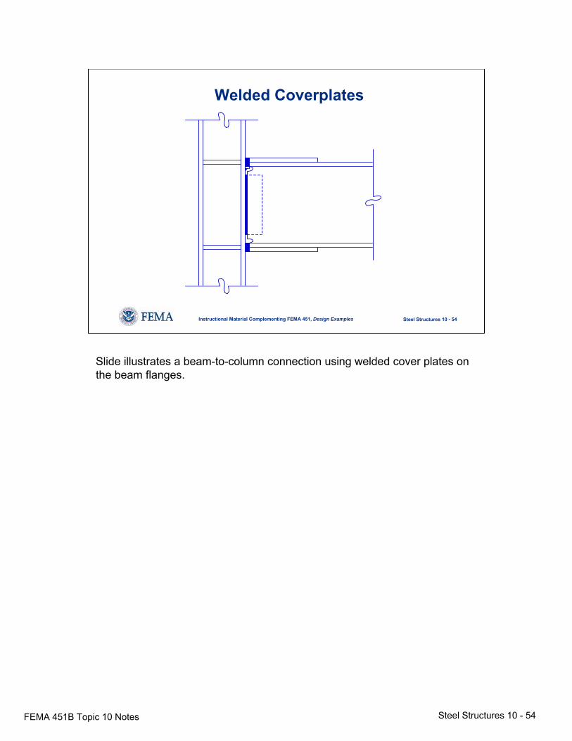
Slide illustrates a beam-to-column connection using welded cover plates on the beam flanges.
FEMA 451B Topic 10 Notes Steel Structures 10 - 55
Steel Structures 10 - 55Instructional Material Complementing FEMA 451, Design Examples
Reduced Beam Section (RBS)
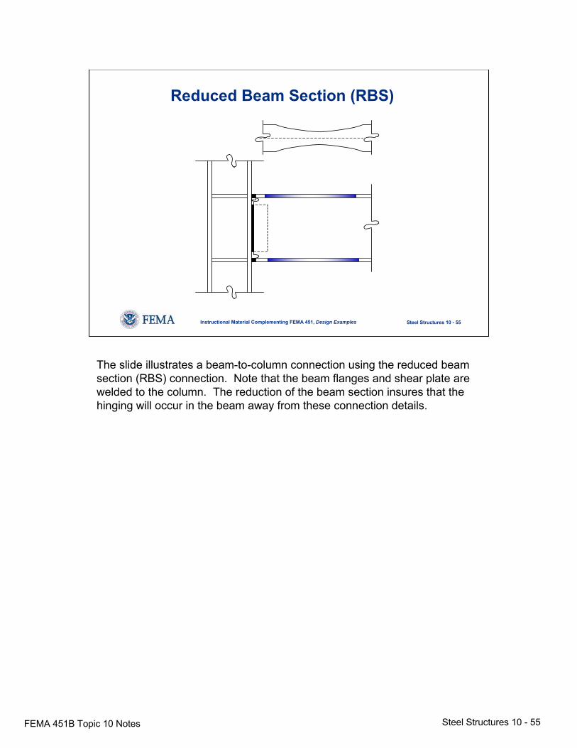
The slide illustrates a beam-to-column connection using the reduced beam section (RBS) connection. Note that the beam flanges and shear plate are welded to the column. The reduction of the beam section insures that the hinging will occur in the beam away from these connection details.
FEMA 451B Topic 10 Notes Steel Structures 10 - 56
Steel Structures 10 - 56Instructional Material Complementing FEMA 451, Design Examples
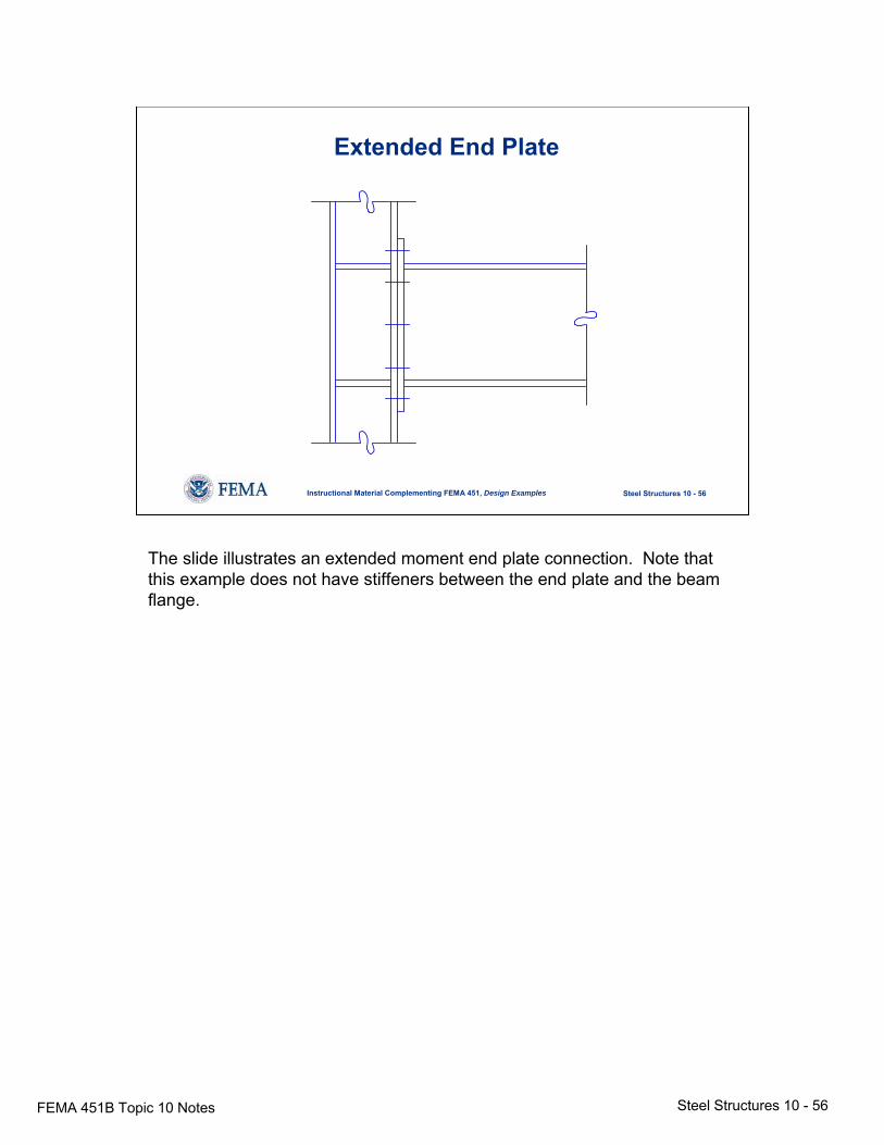
Extended End Plate
The slide illustrates an extended moment end plate connection. Note that this example does not have stiffeners between the end plate and the beam flange.
FEMA 451B Topic 10 Notes Steel Structures 10 - 57
Steel Structures 10 - 57Instructional Material Complementing FEMA 451, Design Examples
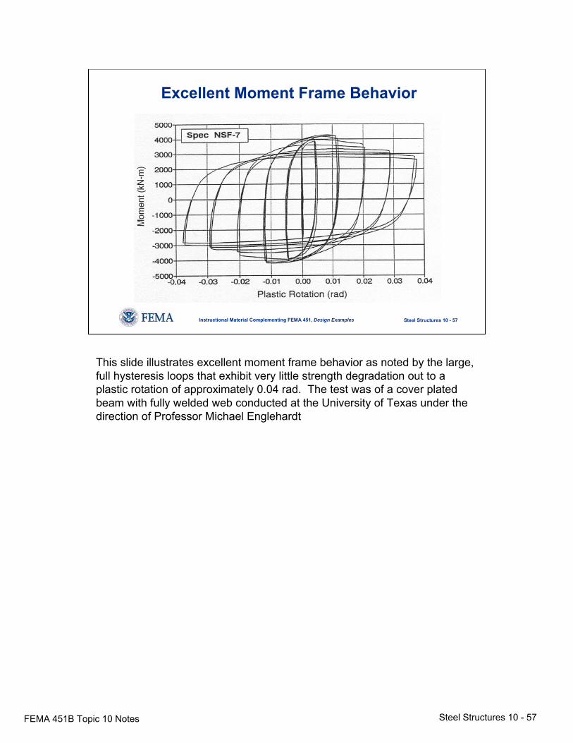
Excellent Moment Frame Behavior
This slide illustrates excellent moment frame behavior as noted by the large, full hysteresis loops that exhibit very little strength degradation out to a plastic rotation of approximately 0.04 rad. The test was of a cover plated beam with fully welded web conducted at the University of Texas under the direction of Professor Michael Englehardt
FEMA 451B Topic 10 Notes Steel Structures 10 - 58
Steel Structures 10 - 58Instructional Material Complementing FEMA 451, Design Examples
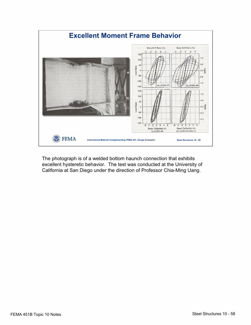
Excellent Moment Frame Behavior
The photograph is of a welded bottom haunch connection that exhibits excellent hysteretic behavior. The test was conducted at the University of California at San Diego under the direction of Professor Chia-Ming Uang.
FEMA 451B Topic 10 Notes Steel Structures 10 - 59
Steel Structures 10 - 59Instructional Material Complementing FEMA 451, Design Examples
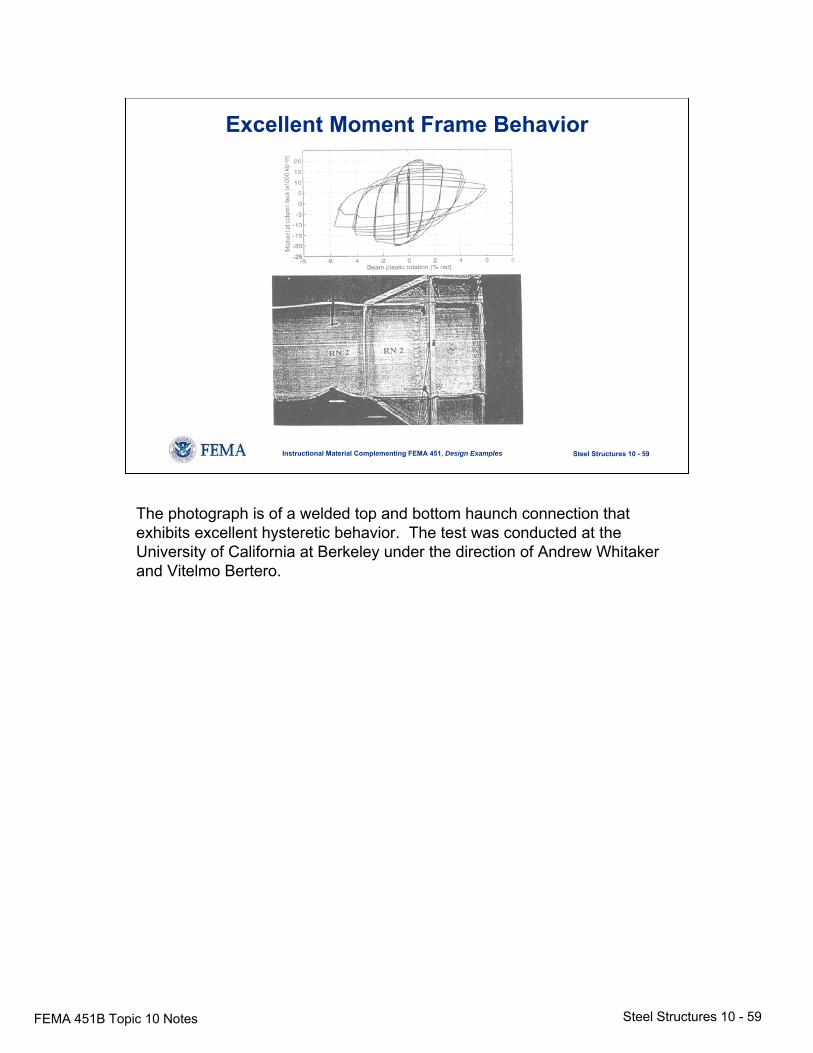
Excellent Moment Frame Behavior
The photograph is of a welded top and bottom haunch connection that exhibits excellent hysteretic behavior. The test was conducted at the University of California at Berkeley under the direction of Andrew Whitaker and Vitelmo Bertero.
FEMA 451B Topic 10 Notes Steel Structures 10 - 60
Steel Structures 10 - 60Instructional Material Complementing FEMA 451, Design Examples
Special Moment FramesExample
5 at
25'
-0"
N
7 at 25'-0"
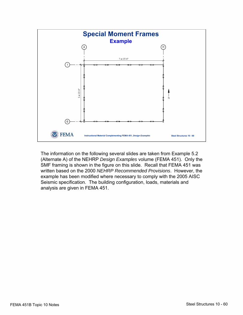
The information on the following several slides are taken from Example 5.2 (Alternate A) of the NEHRP Design Examples volume (FEMA 451). Only the SMF framing is shown in the figure on this slide. Recall that FEMA 451 was written based on the 2000 NEHRP Recommended Provisions. However, the example has been modified where necessary to comply with the 2005 AISC Seismic specification. The building configuration, loads, materials and analysis are given in FEMA 451.
FEMA 451B Topic 10 Notes Steel Structures 10 - 61
Steel Structures 10 - 61Instructional Material Complementing FEMA 451, Design Examples
Special Moment Frames
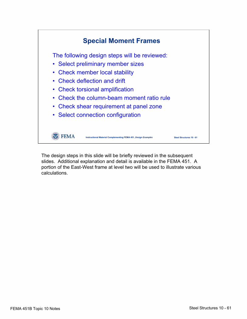
The following design steps will be reviewed:• Select preliminary member sizes• Check member local stability• Check deflection and drift• Check torsional amplification• Check the column-beam moment ratio rule• Check shear requirement at panel zone• Select connection configuration
The design steps in this slide will be briefly reviewed in the subsequent slides. Additional explanation and detail is available in the FEMA 451. A portion of the East-West frame at level two will be used to illustrate various calculations.
FEMA 451B Topic 10 Notes Steel Structures 10 - 62
Steel Structures 10 - 62Instructional Material Complementing FEMA 451, Design Examples
Special Moment Frames
Select preliminary member sizes – The preliminary member sizes are given in the next slide for the frame in the East-West direction. These members were selected based on the use of a 3D stiffness model in the program RAMFRAME. As will be discussed in a subsequent slide, the drift requirements controlled the design of these members.
No additional comments are necessary for this slide.
FEMA 451B Topic 10 Notes Steel Structures 10 - 63
Steel Structures 10 - 63Instructional Material Complementing FEMA 451, Design Examples
SMF Example – Preliminary Member Sizes
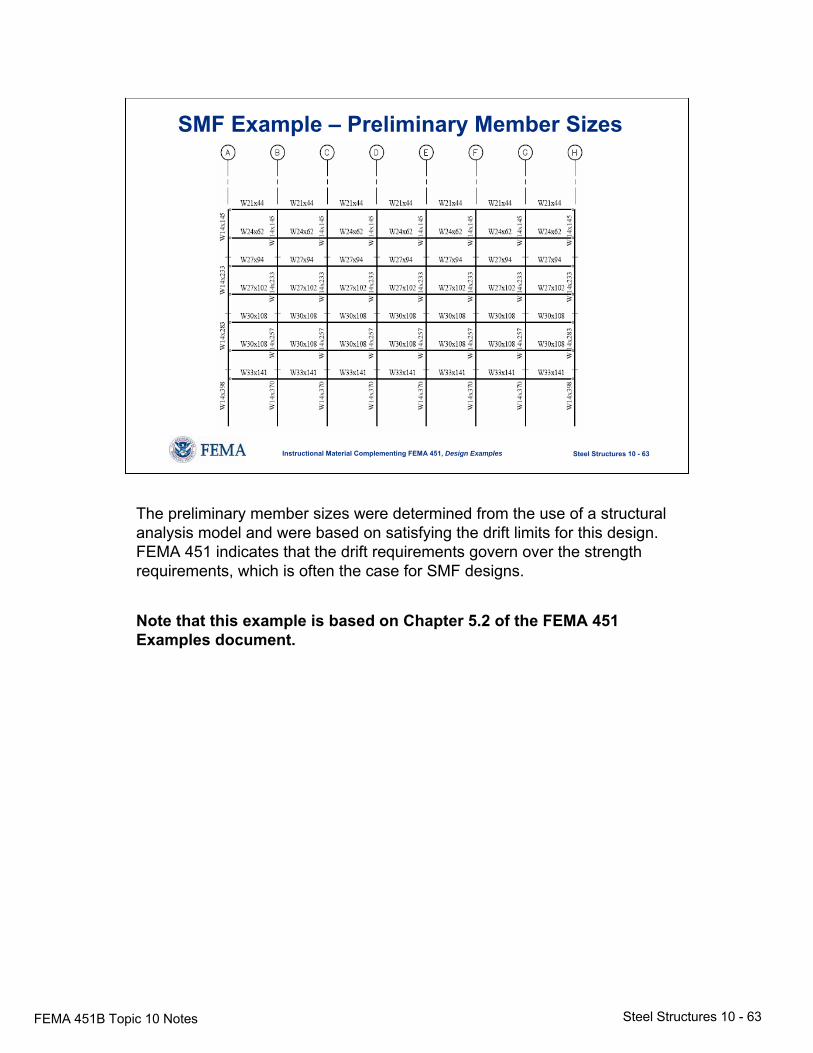
The preliminary member sizes were determined from the use of a structural analysis model and were based on satisfying the drift limits for this design. FEMA 451 indicates that the drift requirements govern over the strength requirements, which is often the case for SMF designs.
Note that this example is based on Chapter 5.2 of the FEMA 451 Examples document.
FEMA 451B Topic 10 Notes Steel Structures 10 - 64
Steel Structures 10 - 64Instructional Material Complementing FEMA 451, Design Examples
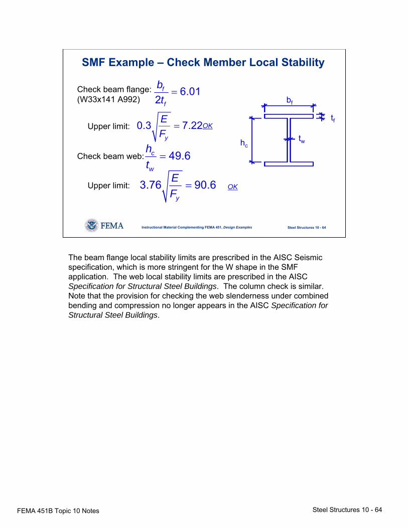
SMF Example – Check Member Local Stability
bf
tf
twhc
Check beam flange:(W33x141 A992)
Upper limit:
Check beam web:
Upper limit:
6.012
f
f
bt=
0.3 7.22y
EF
=
49.6c
w
ht
=
3.76 90.6y
EF
=
OK
OK
The beam flange local stability limits are prescribed in the AISC Seismic specification, which is more stringent for the W shape in the SMF application. The web local stability limits are prescribed in the AISC Specification for Structural Steel Buildings. The column check is similar. Note that the provision for checking the web slenderness under combined bending and compression no longer appears in the AISC Specification for Structural Steel Buildings.
FEMA 451B Topic 10 Notes Steel Structures 10 - 65
Steel Structures 10 - 65Instructional Material Complementing FEMA 451, Design Examples
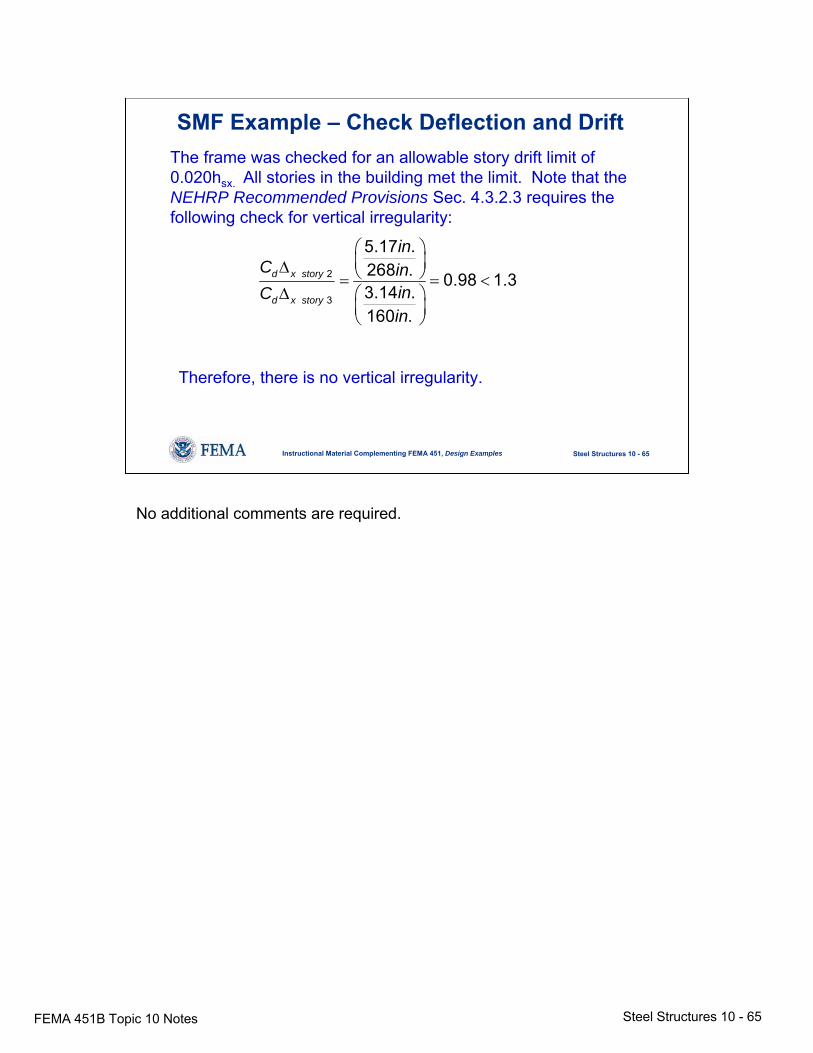
SMF Example – Check Deflection and DriftThe frame was checked for an allowable story drift limit of 0.020hsx. All stories in the building met the limit. Note that the NEHRP Recommended Provisions Sec. 4.3.2.3 requires the following check for vertical irregularity:
2
3
5.17 .268 . 0.98 1.33.14 .160 .
d x story
d x story
inC in
inCin
⎛ ⎞⎜ ⎟Δ ⎝ ⎠= = <
Δ ⎛ ⎞⎜ ⎟⎝ ⎠
Therefore, there is no vertical irregularity.
No additional comments are required.
FEMA 451B Topic 10 Notes Steel Structures 10 - 66
Steel Structures 10 - 66Instructional Material Complementing FEMA 451, Design Examples
SMF Example – Check Torsional Amplification
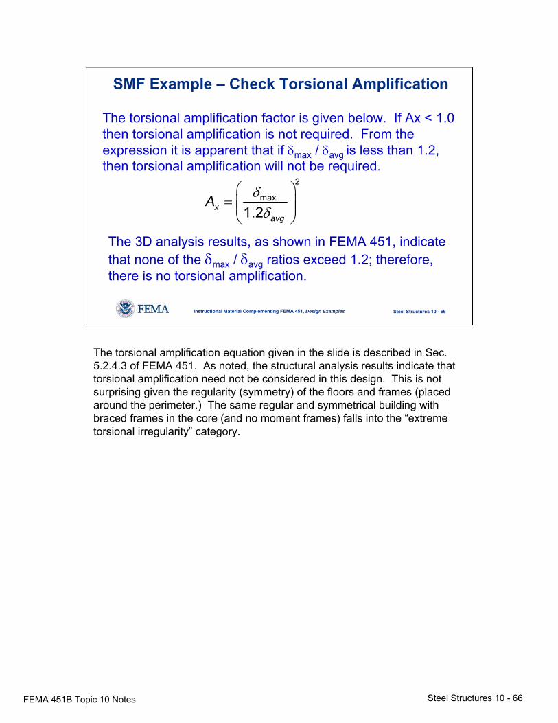
The torsional amplification factor is given below. If Ax < 1.0 then torsional amplification is not required. From the expression it is apparent that if δmax / δavg is less than 1.2, then torsional amplification will not be required.
2
max
1.2xavg
A δδ
⎛ ⎞= ⎜ ⎟⎜ ⎟⎝ ⎠
The 3D analysis results, as shown in FEMA 451, indicate that none of the δmax / δavg ratios exceed 1.2; therefore, there is no torsional amplification.
The torsional amplification equation given in the slide is described in Sec. 5.2.4.3 of FEMA 451. As noted, the structural analysis results indicate that torsional amplification need not be considered in this design. This is not surprising given the regularity (symmetry) of the floors and frames (placed around the perimeter.) The same regular and symmetrical building with braced frames in the core (and no moment frames) falls into the “extreme torsional irregularity” category.
FEMA 451B Topic 10 Notes Steel Structures 10 - 67
Steel Structures 10 - 67Instructional Material Complementing FEMA 451, Design Examples
SMF Example – Member Design NEHRP Guide
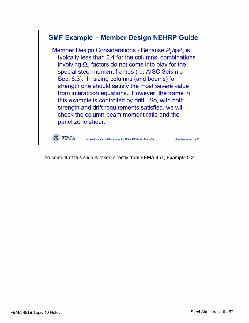
Member Design Considerations - Because Pu/φPn is typically less than 0.4 for the columns, combinations involving Ω0 factors do not come into play for the special steel moment frames (re: AISC Seismic Sec. 8.3). In sizing columns (and beams) for strength one should satisfy the most severe value from interaction equations. However, the frame in this example is controlled by drift. So, with both strength and drift requirements satisfied, we will check the column-beam moment ratio and the panel zone shear.
The content of this slide is taken directly from FEMA 451, Example 5.2.
FEMA 451B Topic 10 Notes Steel Structures 10 - 68
Steel Structures 10 - 68Instructional Material Complementing FEMA 451, Design Examples
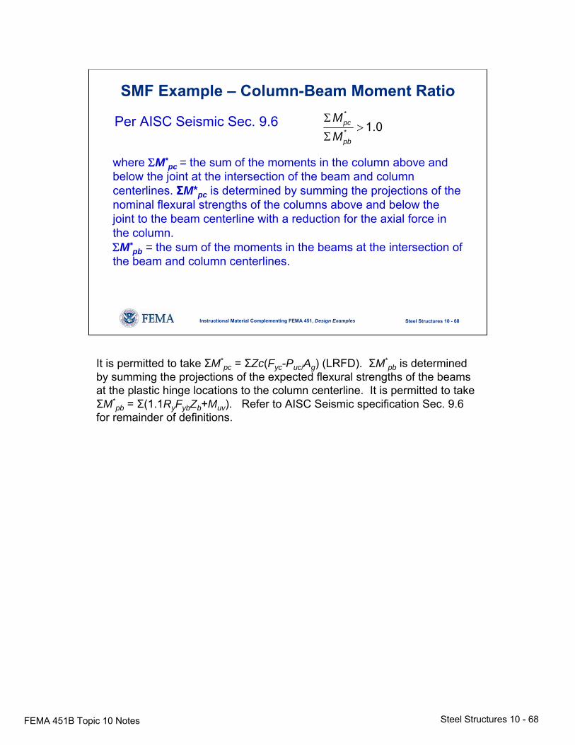
SMF Example – Column-Beam Moment Ratio
Per AISC Seismic Sec. 9.6*
* 1.0pc
pb
MM
Σ>
Σ
where ΣM*pc = the sum of the moments in the column above and
below the joint at the intersection of the beam and column centerlines. ΣM*pc is determined by summing the projections of the nominal flexural strengths of the columns above and below thejoint to the beam centerline with a reduction for the axial force in the column.ΣM*
pb = the sum of the moments in the beams at the intersection of the beam and column centerlines.
It is permitted to take ΣM*pc = ΣZc(Fyc-Puc/Ag) (LRFD). ΣM*
pb is determined by summing the projections of the expected flexural strengths of the beams at the plastic hinge locations to the column centerline. It is permitted to take ΣM*
pb = Σ(1.1RyFybZb+Muv). Refer to AISC Seismic specification Sec. 9.6 for remainder of definitions.
FEMA 451B Topic 10 Notes Steel Structures 10 - 69
Steel Structures 10 - 69Instructional Material Complementing FEMA 451, Design Examples
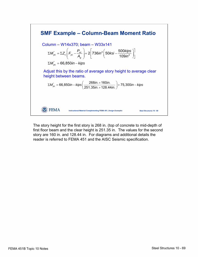
SMF Example – Column-Beam Moment Ratio
Column – W14x370; beam – W33x141
* 22
*
5002 736 50109
66,850
ucpc c yc
g
pc
P kipsM Z F in ksiA in
M in kips
⎛ ⎞ ⎡ ⎤⎛ ⎞Σ = Σ − = −⎜ ⎟ ⎜ ⎟⎢ ⎥⎜ ⎟ ⎝ ⎠⎣ ⎦⎝ ⎠Σ = −
Adjust this by the ratio of average story height to average clear height between beams.
* 268 . 160 .66,850 75,300251.35 . 128.44 .pc
in inM in kips in kipsin in
+⎛ ⎞Σ = − = −⎜ ⎟+⎝ ⎠
The story height for the first story is 268 in. (top of concrete to mid-depth of first floor beam and the clear height is 251.35 in. The values for the second story are 160 in. and 128.44 in. For diagrams and additional details the reader is referred to FEMA 451 and the AISC Seismic specification.
FEMA 451B Topic 10 Notes Steel Structures 10 - 70
Steel Structures 10 - 70Instructional Material Complementing FEMA 451, Design Examples
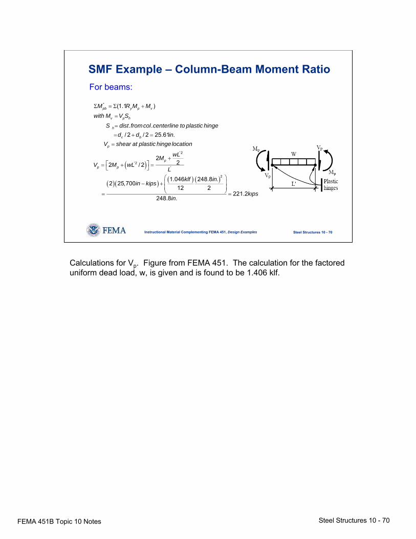
SMF Example – Column-Beam Moment RatioFor beams:
( )
( )( ) ( ) ( )
*
' 2
' 2'
2
(1.1 )
. ./ 2 / 2 25.61 .
222 / 2
1.046 248.8 .2 25,700
12 2
248.8 .
pb y p v
v p h
h
c b
p
p
p p
M R M M
with M V S
S dist fromcol centerline to plastic hinged d in
V shear at plastic hinge location
wLMV M wL
L
klf inin kips
in
Σ = Σ +
=
=
= + =
=
+⎡ ⎤= + =⎣ ⎦
⎛ ⎞⎜ ⎟− +⎜ ⎟⎝ ⎠= 221.2kips=
Calculations for Vp. Figure from FEMA 451. The calculation for the factored uniform dead load, w, is given and is found to be 1.406 klf.
FEMA 451B Topic 10 Notes Steel Structures 10 - 71
Steel Structures 10 - 71Instructional Material Complementing FEMA 451, Design Examples
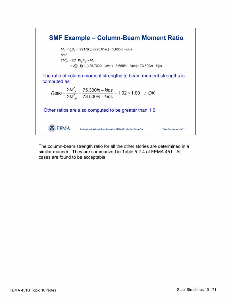
SMF Example – Column-Beam Moment Ratio
*
(221.2 )(25.61 .) 5,665
(1.1 )
2[(1.1)(1.1)(25,700 ) 5,665 ] 73,500
v p h
pb y p v
M V S kips in in kips
andM R M M
in kips in kips in kips
= = = −
Σ = Σ +
= − + − = −
The ratio of column moment strengths to beam moment strengths iscomputed as:
*
*75,300 1.02 1.0073,500
pc
pb
M in kipsRatio OKM in kips
Σ −= = = > ∴Σ −
Other ratios are also computed to be greater than 1.0
The column-beam strength ratio for all the other stories are determined in a similar manner. They are summarized in Table 5.2-4 of FEMA 451. All cases are found to be acceptable.
FEMA 451B Topic 10 Notes Steel Structures 10 - 72
Steel Structures 10 - 72Instructional Material Complementing FEMA 451, Design Examples
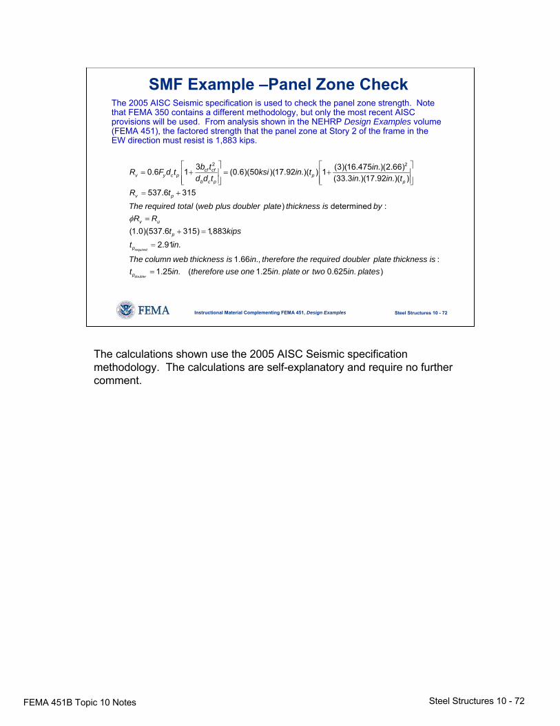
SMF Example –Panel Zone CheckThe 2005 AISC Seismic specification is used to check the panel zone strength. Note that FEMA 350 contains a different methodology, but only the most recent AISC provisions will be used. From analysis shown in the NEHRP Design Examples volume(FEMA 451), the factored strength that the panel zone at Story 2 of the frame in the EW direction must resist is 1,883 kips.
2 23 (3)(16.475 .)(2.66)0.6 1 (0.6)(50 )(17.92 .)( ) 1(33.3 .)(17.92 .)( )
537.6 315
( ) determined :
(1
cf cfv y c p p
b c p p
v p
v u
b t inR F d t ksi in td d t in in t
R t
The required total web plus doubler plate thickness is byR Rφ
⎡ ⎤ ⎡ ⎤= + = +⎢ ⎥ ⎢ ⎥
⎢ ⎥ ⎢ ⎥⎣ ⎦ ⎣ ⎦= +
=
.0)(537.6 315) 1,8832.91 .
1.66 ., :1.25 . ( 1.25 . 0.625 . )
required
doubler
p
p
p
t kips
t in
The column web thickness is in therefore the required doubler plate thickness ist in therefore use one in plate or two in plates
+ =
=
=
The calculations shown use the 2005 AISC Seismic specification methodology. The calculations are self-explanatory and require no further comment.
FEMA 451B Topic 10 Notes Steel Structures 10 - 73
Steel Structures 10 - 73Instructional Material Complementing FEMA 451, Design Examples
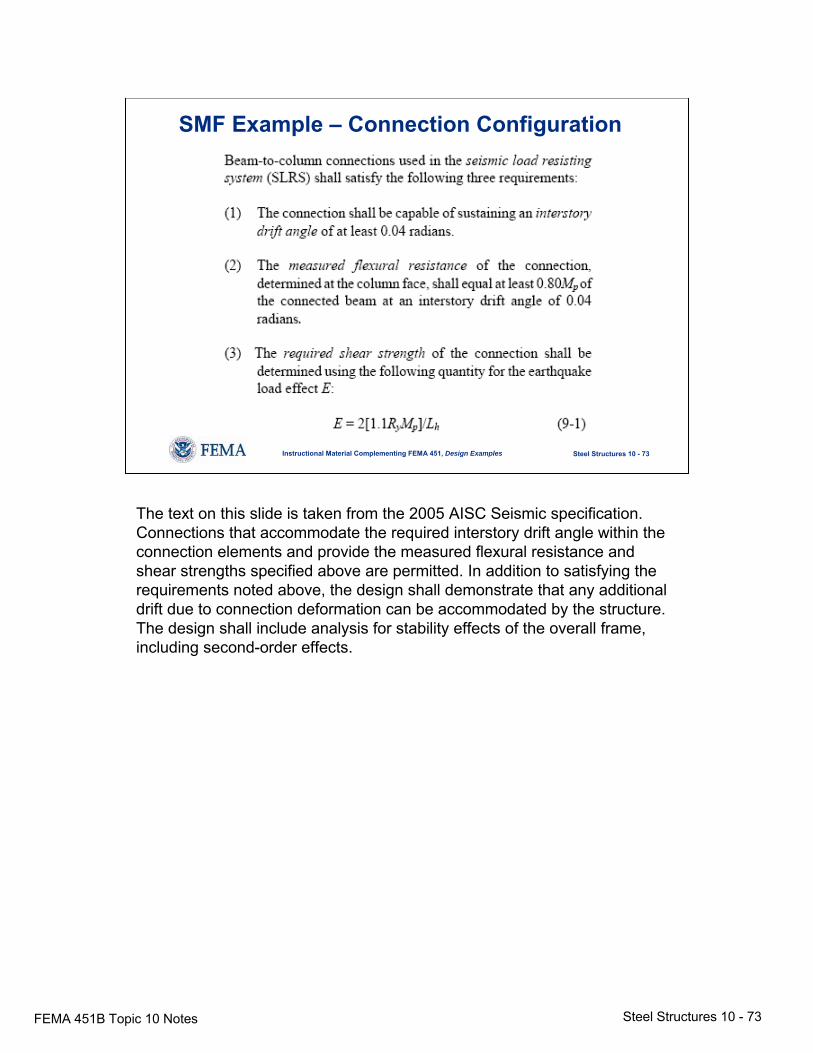
SMF Example – Connection Configuration
The text on this slide is taken from the 2005 AISC Seismic specification. Connections that accommodate the required interstory drift angle within the connection elements and provide the measured flexural resistance and shear strengths specified above are permitted. In addition to satisfying the requirements noted above, the design shall demonstrate that any additional drift due to connection deformation can be accommodated by the structure. The design shall include analysis for stability effects of the overall frame, including second-order effects.
FEMA 451B Topic 10 Notes Steel Structures 10 - 74
Steel Structures 10 - 74Instructional Material Complementing FEMA 451, Design Examples
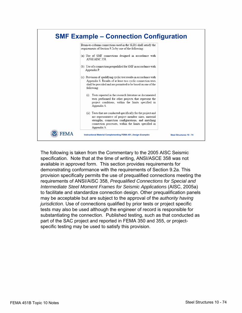
SMF Example – Connection Configuration
The following is taken from the Commentary to the 2005 AISC Seismic specification. Note that at the time of writing, ANSI/ASCE 358 was not available in approved form. This section provides requirements for demonstrating conformance with the requirements of Section 9.2a. This provision specifically permits the use of prequalified connections meeting the requirements of ANSI/AISC 358, Prequalified Connections for Special and Intermediate Steel Moment Frames for Seismic Applications (AISC, 2005a) to facilitate and standardize connection design. Other prequalification panels may be acceptable but are subject to the approval of the authority having jurisdiction. Use of connections qualified by prior tests or project specific tests may also be used although the engineer of record is responsible for substantiating the connection. Published testing, such as that conducted as part of the SAC project and reported in FEMA 350 and 355, or project-specific testing may be used to satisfy this provision.
FEMA 451B Topic 10 Notes Steel Structures 10 - 75
Steel Structures 10 - 75Instructional Material Complementing FEMA 451, Design Examples
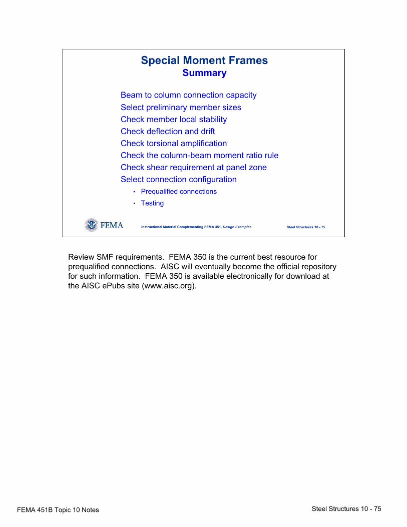
Special Moment FramesSummary
Beam to column connection capacitySelect preliminary member sizesCheck member local stabilityCheck deflection and driftCheck torsional amplificationCheck the column-beam moment ratio ruleCheck shear requirement at panel zoneSelect connection configuration
• Prequalified connections
• Testing
Review SMF requirements. FEMA 350 is the current best resource for prequalified connections. AISC will eventually become the official repository for such information. FEMA 350 is available electronically for download at the AISC ePubs site (www.aisc.org).
FEMA 451B Topic 10 Notes Steel Structures 10 - 76
Steel Structures 10 - 76Instructional Material Complementing FEMA 451, Design Examples
NEHRP Recommended ProvisionsSteel Design
• Context in Provisions• Steel behavior• Reference standards and design strength• Seismic design category requirement• Moment resisting frames• Braced frames
Table of Contents: braced frames.
FEMA 451B Topic 10 Notes Steel Structures 10 - 77
Steel Structures 10 - 77Instructional Material Complementing FEMA 451, Design Examples
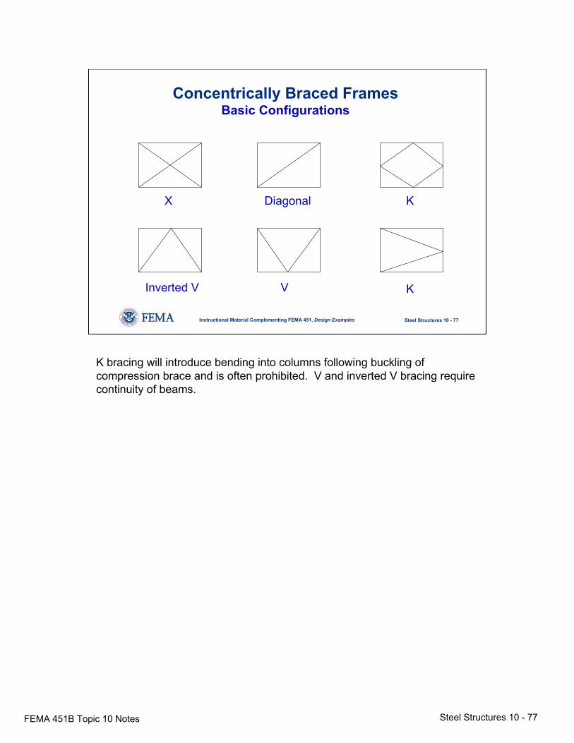
Concentrically Braced FramesBasic Configurations
X Diagonal K
VInverted V K
K bracing will introduce bending into columns following buckling of compression brace and is often prohibited. V and inverted V bracing require continuity of beams.
FEMA 451B Topic 10 Notes Steel Structures 10 - 78
Steel Structures 10 - 78Instructional Material Complementing FEMA 451, Design Examples
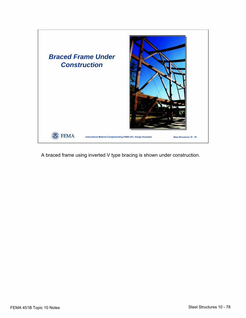
Braced Frame Under Construction
A braced frame using inverted V type bracing is shown under construction.
FEMA 451B Topic 10 Notes Steel Structures 10 - 79
Steel Structures 10 - 79Instructional Material Complementing FEMA 451, Design Examples
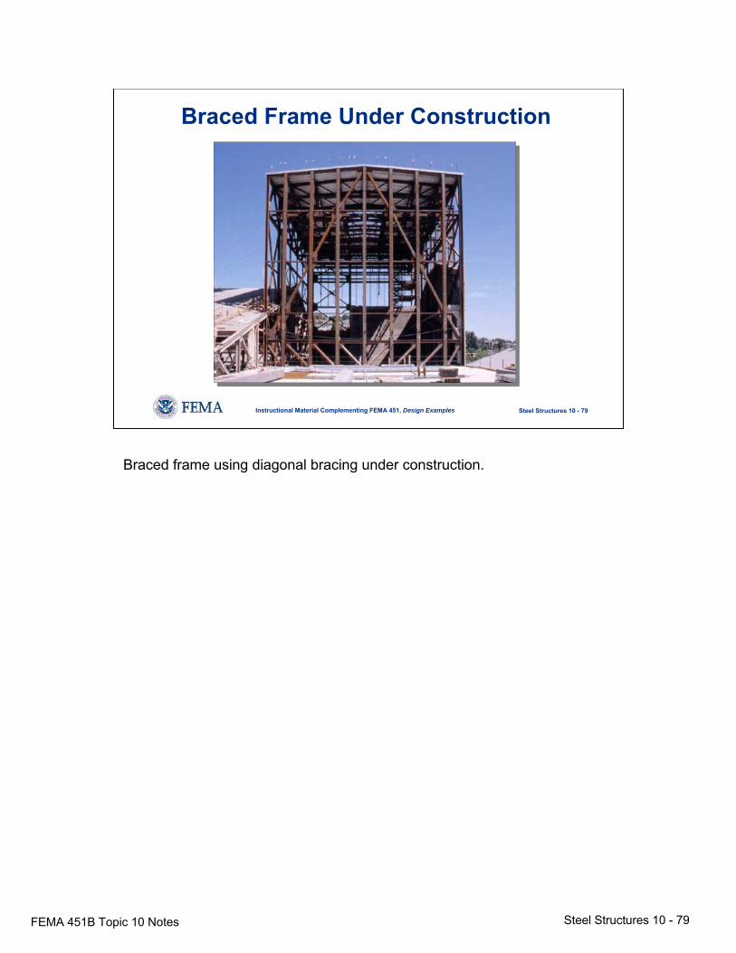
Braced Frame Under Construction
Braced frame using diagonal bracing under construction.
FEMA 451B Topic 10 Notes Steel Structures 10 - 80
Steel Structures 10 - 80Instructional Material Complementing FEMA 451, Design Examples
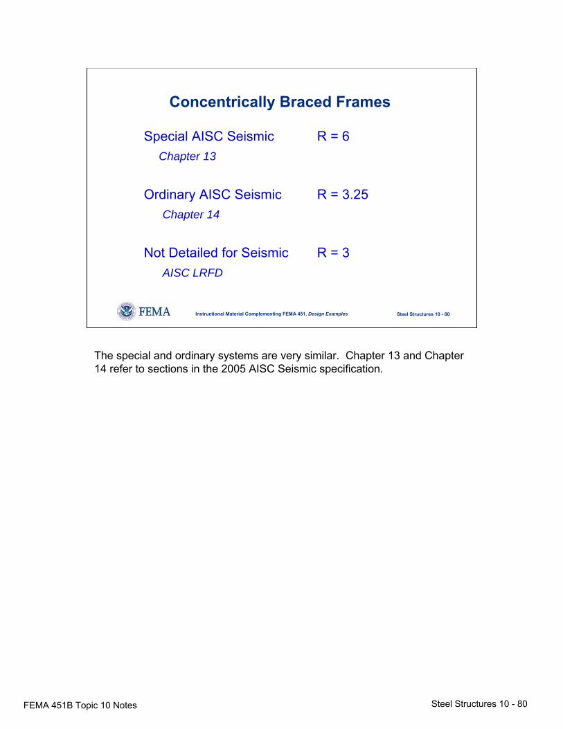
Concentrically Braced Frames
Special AISC Seismic R = 6Chapter 13
Ordinary AISC Seismic R = 3.25Chapter 14
Not Detailed for Seismic R = 3AISC LRFD
The special and ordinary systems are very similar. Chapter 13 and Chapter 14 refer to sections in the 2005 AISC Seismic specification.
FEMA 451B Topic 10 Notes Steel Structures 10 - 81
Steel Structures 10 - 81Instructional Material Complementing FEMA 451, Design Examples
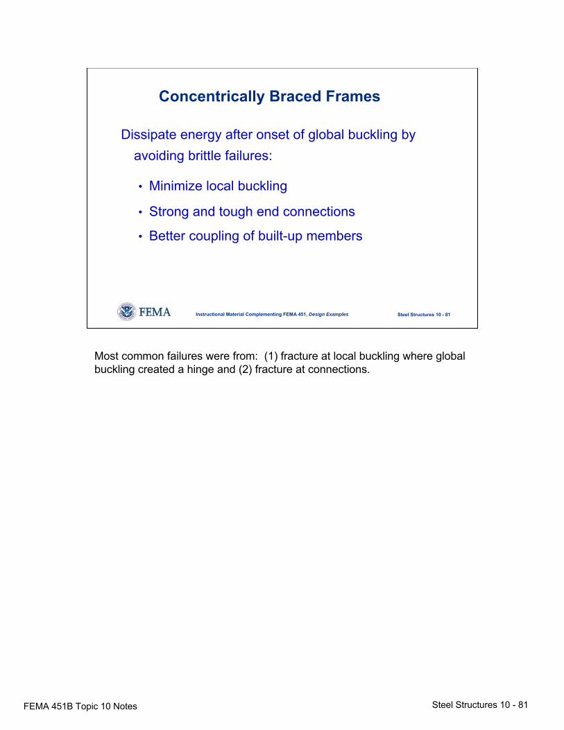
Concentrically Braced Frames
Dissipate energy after onset of global buckling by avoiding brittle failures:
• Minimize local buckling
• Strong and tough end connections
• Better coupling of built-up members
Most common failures were from: (1) fracture at local buckling where global buckling created a hinge and (2) fracture at connections.
FEMA 451B Topic 10 Notes Steel Structures 10 - 82
Steel Structures 10 - 82Instructional Material Complementing FEMA 451, Design Examples
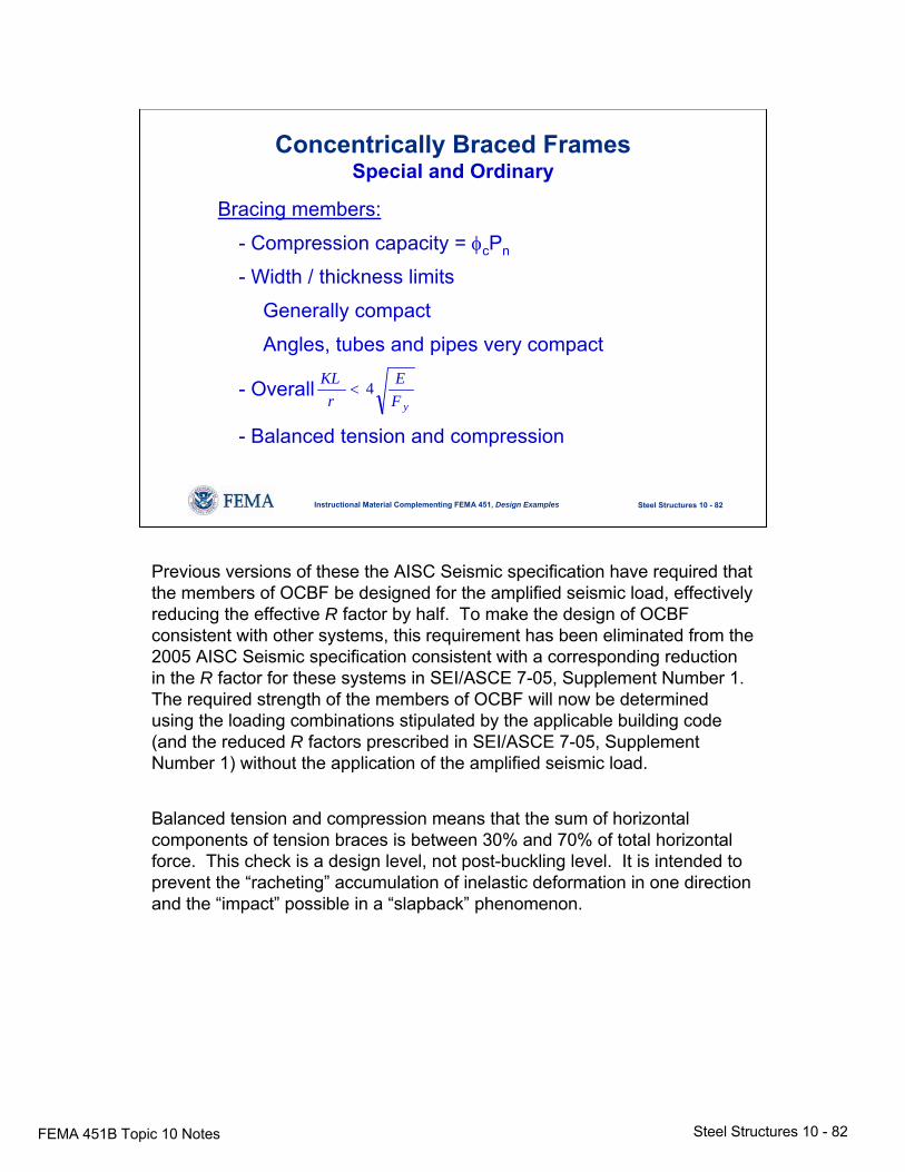
Concentrically Braced FramesSpecial and Ordinary
Bracing members:
- Compression capacity = φcPn
- Width / thickness limits
Generally compact
Angles, tubes and pipes very compact
- Overall
- Balanced tension and compressionyF
Er
KL 4<
Previous versions of these the AISC Seismic specification have required that the members of OCBF be designed for the amplified seismic load, effectively reducing the effective R factor by half. To make the design of OCBF consistent with other systems, this requirement has been eliminated from the 2005 AISC Seismic specification consistent with a corresponding reduction in the R factor for these systems in SEI/ASCE 7-05, Supplement Number 1. The required strength of the members of OCBF will now be determined using the loading combinations stipulated by the applicable building code (and the reduced R factors prescribed in SEI/ASCE 7-05, Supplement Number 1) without the application of the amplified seismic load.
Balanced tension and compression means that the sum of horizontal components of tension braces is between 30% and 70% of total horizontal force. This check is a design level, not post-buckling level. It is intended to prevent the “racheting” accumulation of inelastic deformation in one direction and the “impact” possible in a “slapback” phenomenon.
FEMA 451B Topic 10 Notes Steel Structures 10 - 83
Steel Structures 10 - 83Instructional Material Complementing FEMA 451, Design Examples
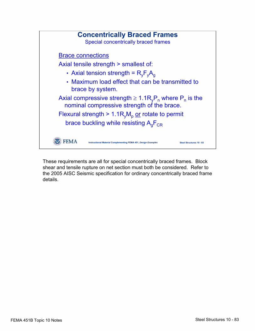
Concentrically Braced FramesSpecial concentrically braced frames
Brace connectionsAxial tensile strength > smallest of:
• Axial tension strength = RyFyAg
• Maximum load effect that can be transmitted to brace by system.
Axial compressive strength ≥ 1.1RyPn where Pn is the nominal compressive strength of the brace.
Flexural strength > 1.1RyMp or rotate to permitbrace buckling while resisting AgFCR
These requirements are all for special concentrically braced frames. Block shear and tensile rupture on net section must both be considered. Refer to the 2005 AISC Seismic specification for ordinary concentrically braced frame details.
FEMA 451B Topic 10 Notes Steel Structures 10 - 84
Steel Structures 10 - 84Instructional Material Complementing FEMA 451, Design Examples
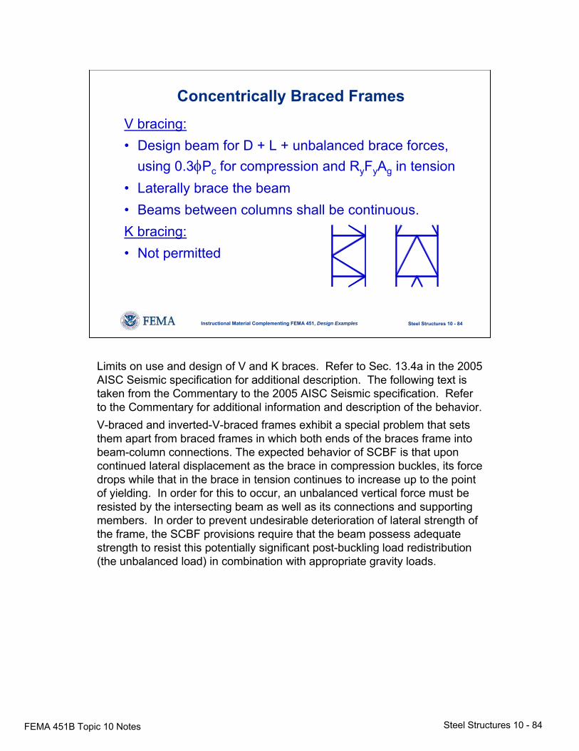
Concentrically Braced FramesV bracing:• Design beam for D + L + unbalanced brace forces,
using 0.3φPc for compression and RyFyAg in tension• Laterally brace the beam• Beams between columns shall be continuous.K bracing:• Not permitted
Limits on use and design of V and K braces. Refer to Sec. 13.4a in the 2005 AISC Seismic specification for additional description. The following text is taken from the Commentary to the 2005 AISC Seismic specification. Refer to the Commentary for additional information and description of the behavior.V-braced and inverted-V-braced frames exhibit a special problem that sets them apart from braced frames in which both ends of the braces frame into beam-column connections. The expected behavior of SCBF is that upon continued lateral displacement as the brace in compression buckles, its force drops while that in the brace in tension continues to increase up to the point of yielding. In order for this to occur, an unbalanced vertical force must be resisted by the intersecting beam as well as its connections and supporting members. In order to prevent undesirable deterioration of lateral strength of the frame, the SCBF provisions require that the beam possess adequate strength to resist this potentially significant post-buckling load redistribution (the unbalanced load) in combination with appropriate gravity loads.
FEMA 451B Topic 10 Notes Steel Structures 10 - 85
Steel Structures 10 - 85Instructional Material Complementing FEMA 451, Design Examples
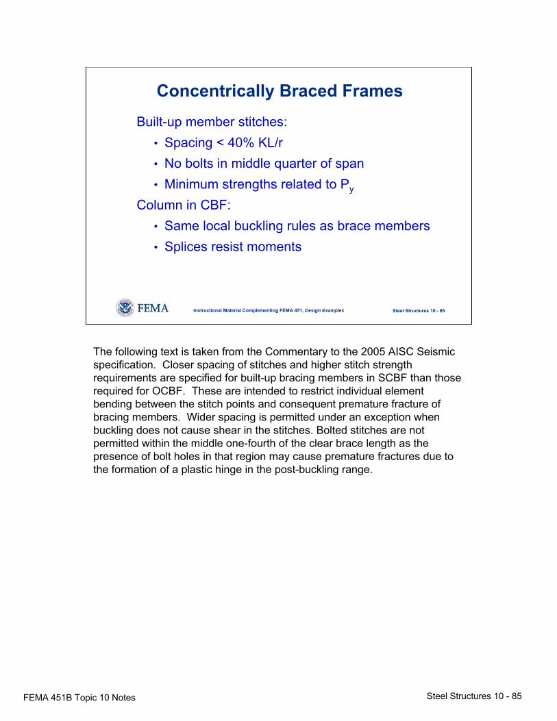
Concentrically Braced FramesBuilt-up member stitches:
• Spacing < 40% KL/r• No bolts in middle quarter of span• Minimum strengths related to Py
Column in CBF:• Same local buckling rules as brace members• Splices resist moments
The following text is taken from the Commentary to the 2005 AISC Seismic specification. Closer spacing of stitches and higher stitch strength requirements are specified for built-up bracing members in SCBF than those required for OCBF. These are intended to restrict individual element bending between the stitch points and consequent premature fracture of bracing members. Wider spacing is permitted under an exception when buckling does not cause shear in the stitches. Bolted stitches are not permitted within the middle one-fourth of the clear brace length as the presence of bolt holes in that region may cause premature fractures due to the formation of a plastic hinge in the post-buckling range.
FEMA 451B Topic 10 Notes Steel Structures 10 - 86
Steel Structures 10 - 86Instructional Material Complementing FEMA 451, Design Examples
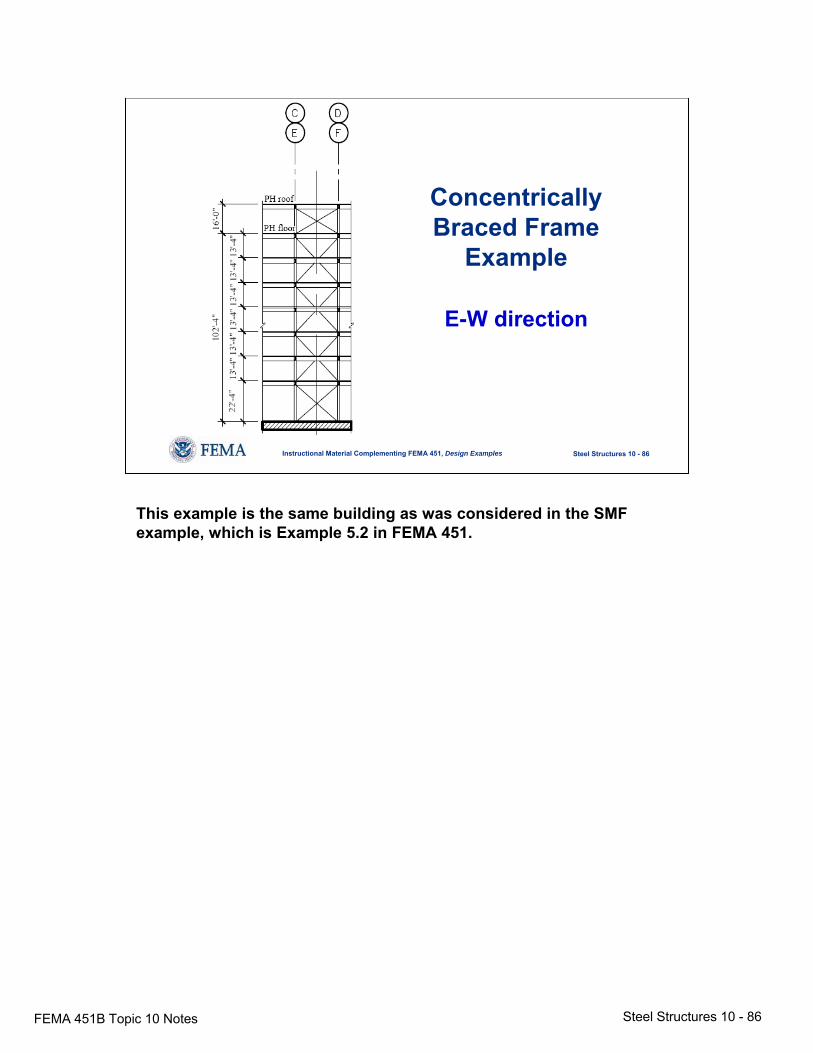
Concentrically Braced Frame
Example
E-W direction
This example is the same building as was considered in the SMF example, which is Example 5.2 in FEMA 451.

FEMA 451B Topic 10 Notes Steel Structures 10 - 87
Steel Structures 10 - 87Instructional Material Complementing FEMA 451, Design Examples
Concentrically Braced Frame Example
The following general design steps are required:• Selection of preliminary member sizes• Check strength• Check drift• Check torsional amplification• Connection design
The general design steps for a SCBF are indicated on the slide. The load and analysis calculations, along with a summary of each of these steps are given in FEMA 451.
FEMA 451B Topic 10 Notes Steel Structures 10 - 88
Steel Structures 10 - 88Instructional Material Complementing FEMA 451, Design Examples
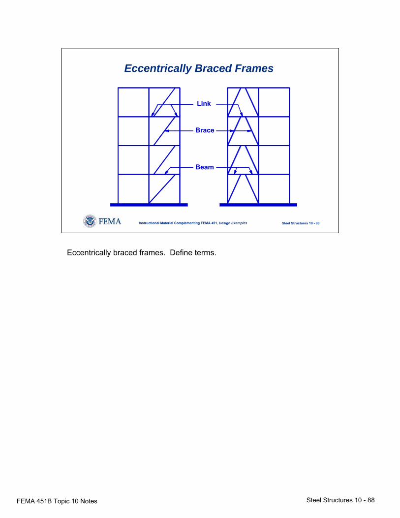
Eccentrically Braced Frames
Link
Brace
Beam
Eccentrically braced frames. Define terms.
FEMA 451B Topic 10 Notes Steel Structures 10 - 89
Steel Structures 10 - 89Instructional Material Complementing FEMA 451, Design Examples
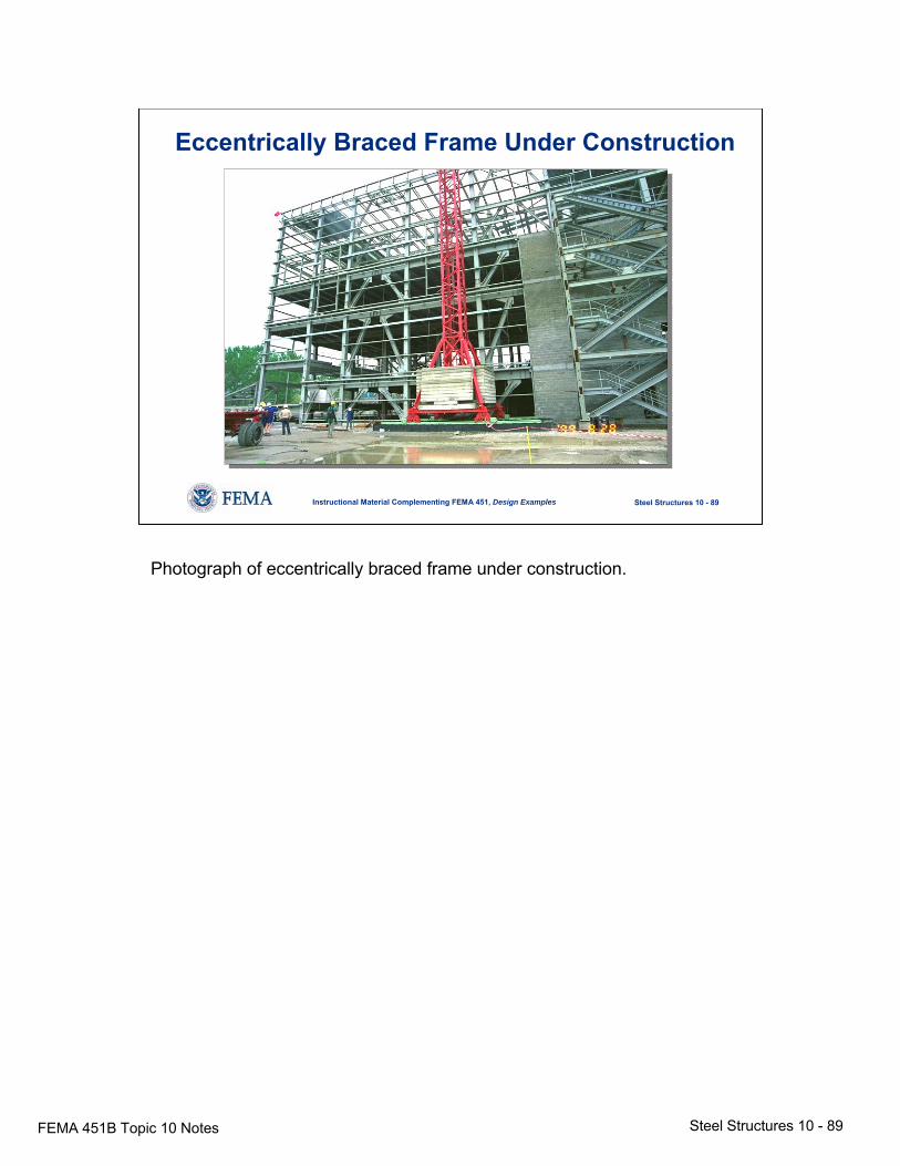
Eccentrically Braced Frame Under Construction
Photograph of eccentrically braced frame under construction.
FEMA 451B Topic 10 Notes Steel Structures 10 - 90
Steel Structures 10 - 90Instructional Material Complementing FEMA 451, Design Examples
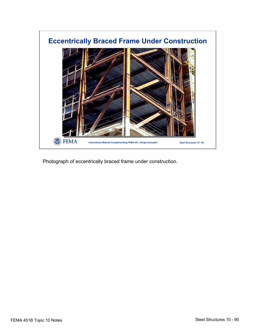
Eccentrically Braced Frame Under Construction
Photograph of eccentrically braced frame under construction.
FEMA 451B Topic 10 Notes Steel Structures 10 - 91
Steel Structures 10 - 91Instructional Material Complementing FEMA 451, Design Examples
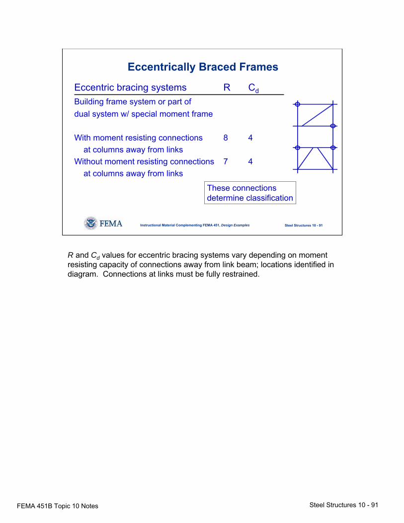
Eccentrically Braced Frames
Eccentric bracing systems R Cd
Building frame system or part ofdual system w/ special moment frame
With moment resisting connections 8 4at columns away from links
Without moment resisting connections 7 4at columns away from links
These connectionsdetermine classification
R and Cd values for eccentric bracing systems vary depending on moment resisting capacity of connections away from link beam; locations identified in diagram. Connections at links must be fully restrained.
FEMA 451B Topic 10 Notes Steel Structures 10 - 92
Steel Structures 10 - 92Instructional Material Complementing FEMA 451, Design Examples
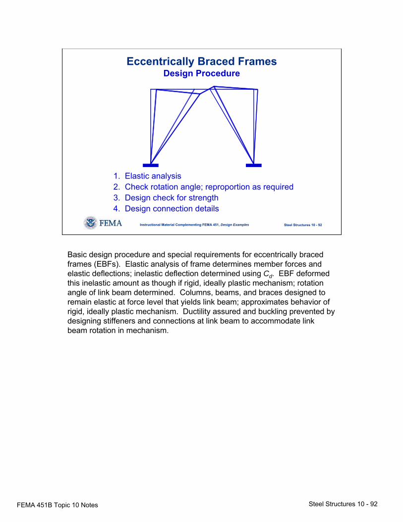
Eccentrically Braced FramesDesign Procedure
1. Elastic analysis2. Check rotation angle; reproportion as required3. Design check for strength4. Design connection details
Basic design procedure and special requirements for eccentrically braced frames (EBFs). Elastic analysis of frame determines member forces and elastic deflections; inelastic deflection determined using Cd. EBF deformed this inelastic amount as though if rigid, ideally plastic mechanism; rotation angle of link beam determined. Columns, beams, and braces designed to remain elastic at force level that yields link beam; approximates behavior of rigid, ideally plastic mechanism. Ductility assured and buckling prevented by designing stiffeners and connections at link beam to accommodate link beam rotation in mechanism.
FEMA 451B Topic 10 Notes Steel Structures 10 - 93
Steel Structures 10 - 93Instructional Material Complementing FEMA 451, Design Examples
Eccentrically Braced FramesExample
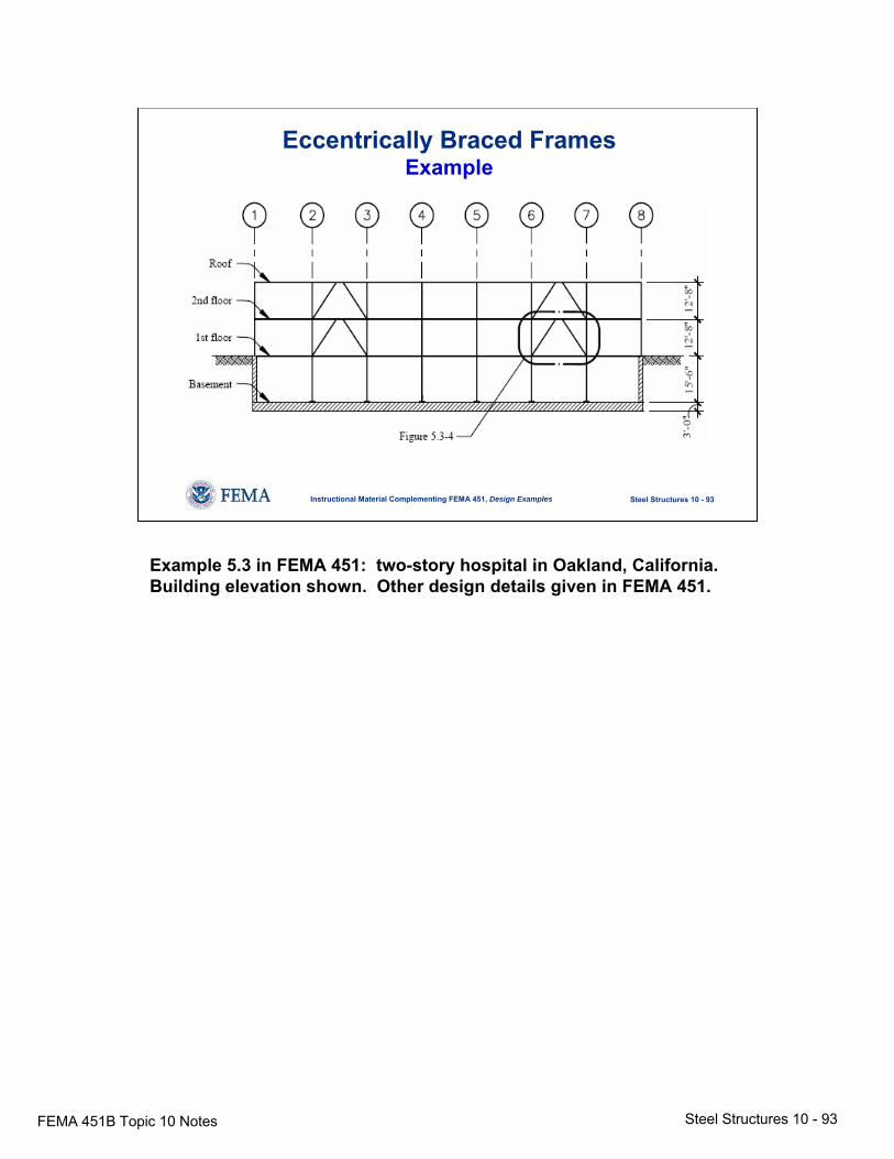
Example 5.3 in FEMA 451: two-story hospital in Oakland, California. Building elevation shown. Other design details given in FEMA 451.
FEMA 451B Topic 10 Notes Steel Structures 10 - 94
Steel Structures 10 - 94Instructional Material Complementing FEMA 451, Design Examples
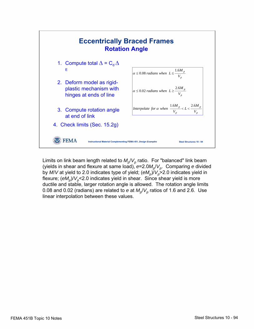
Eccentrically Braced FramesRotation Angle
1. Compute total Δ = Cd ΔE
2. Deform model as rigid-plastic mechanism with hinges at ends of line
3. Compute rotation angle at end of link
p
p
p
p
p
p
p
p
VM
LVM
whenforeInterpolat
VM
Lwhenradians
VM
Lwhenradians
6.26.1
6.202.0
6.108.0
<<
≥≤
≤≤
α
α
α
4. Check limits (Sec. 15.2g)
Limits on link beam length related to Mp/Vp ratio. For "balanced" link beam (yields in shear and flexure at same load), e=2.0Mp/Vp. Comparing e divided by M/V at yield to 2.0 indicates type of yield; (eMp)/Vp>2.0 indicates yield in flexure; (eMp)/Vp<2.0 indicates yield in shear. Since shear yield is more ductile and stable, larger rotation angle is allowed. The rotation angle limits 0.08 and 0.02 (radians) are related to e at Mp/Vp ratios of 1.6 and 2.6. Use linear interpolation between these values.
FEMA 451B Topic 10 Notes Steel Structures 10 - 95
Steel Structures 10 - 95Instructional Material Complementing FEMA 451, Design Examples
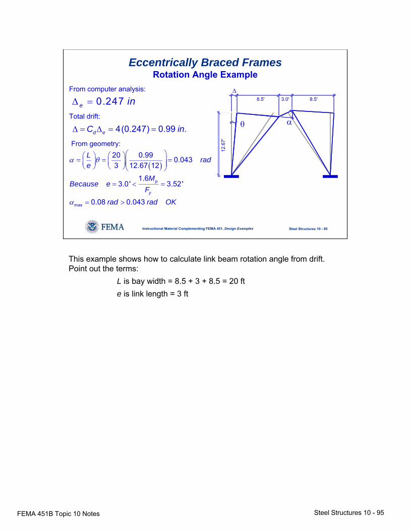
Eccentrically Braced FramesRotation Angle Example
8.5' 3.0' 8.5'
12.6
7'
θ
Δ
α
From computer analysis:
Total drift:
From geometry:
0.247e inΔ =
4(0.247) 0.99 .d eC inΔ = Δ = =
( )
max
20 0.99 0.0433 12.67 12
1.63.0' 3.52'
0.08 0.043
p
y
L rade
MBecause e
F
rad rad OK
α θ
α
⎛ ⎞⎛ ⎞ ⎛ ⎞= = =⎜ ⎟⎜ ⎟ ⎜ ⎟⎜ ⎟⎝ ⎠ ⎝ ⎠⎝ ⎠
= < =
= >
This example shows how to calculate link beam rotation angle from drift. Point out the terms:
L is bay width = 8.5 + 3 + 8.5 = 20 fte is link length = 3 ft
FEMA 451B Topic 10 Notes Steel Structures 10 - 96
Steel Structures 10 - 96Instructional Material Complementing FEMA 451, Design Examples
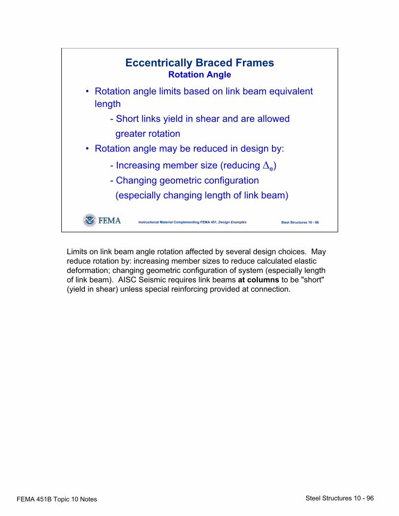
Eccentrically Braced FramesRotation Angle
• Rotation angle limits based on link beam equivalent length
- Short links yield in shear and are allowedgreater rotation
• Rotation angle may be reduced in design by:
- Increasing member size (reducing Δe)- Changing geometric configuration
(especially changing length of link beam)
Limits on link beam angle rotation affected by several design choices. May reduce rotation by: increasing member sizes to reduce calculated elastic deformation; changing geometric configuration of system (especially length of link beam). AISC Seismic requires link beams at columns to be "short" (yield in shear) unless special reinforcing provided at connection.
FEMA 451B Topic 10 Notes Steel Structures 10 - 97
Steel Structures 10 - 97Instructional Material Complementing FEMA 451, Design Examples
Eccentrically Braced FramesLink Design
• Provide strength V and M per load combinations• Check lateral bracing per AISC Lpd
• Local buckling (width to thickness of web and flange) per AISC Seismic
• Stiffeners (end and intermediate) perAISC Seismic
Summary of link design procedure.
FEMA 451B Topic 10 Notes Steel Structures 10 - 98
Steel Structures 10 - 98Instructional Material Complementing FEMA 451, Design Examples
Eccentrically Braced FramesBrace Design
⎟⎠⎞⎜
⎝⎛⋅> linkofstrengthshear
designfromforceaxialR25.1Strength y
Brace strength requirement for EBFs. Member buckling should not occur in EBFs.
FEMA 451B Topic 10 Notes Steel Structures 10 - 99
Steel Structures 10 - 99Instructional Material Complementing FEMA 451, Design Examples
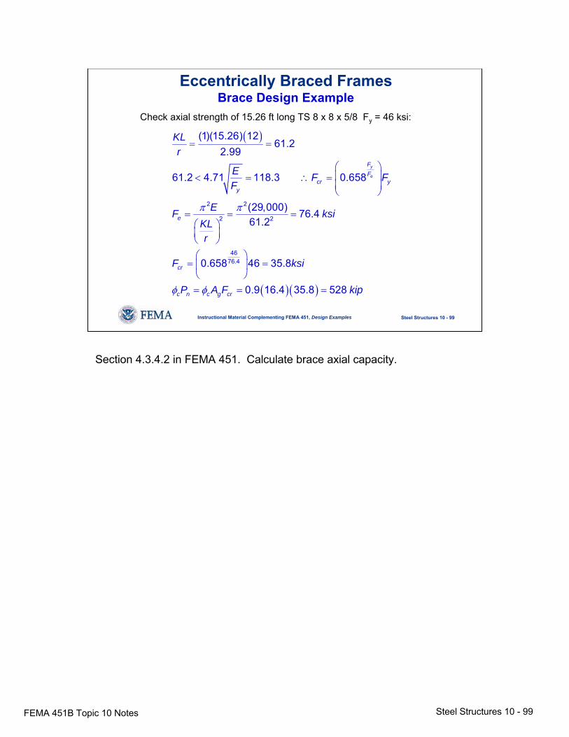
Eccentrically Braced FramesBrace Design Example
Check axial strength of 15.26 ft long TS 8 x 8 x 5/8 Fy = 46 ksi:
( )
( )( )
2 2
2 2
4676.4
(1)(15.26) 1261.2
2.99
61.2 4.71 118.3 0.658
(29,000) 76.461.2
0.658 46 35.8
0.9 16.4 35.8 528
y
e
FF
cr yy
e
cr
c n c g cr
KLr
E F FF
EF ksiKLr
F ksi
P A F kip
π π
φ φ
= =
⎛ ⎞⎜ ⎟< = ∴ =⎜ ⎟⎝ ⎠
= = =⎛ ⎞⎜ ⎟⎝ ⎠⎛ ⎞
= =⎜ ⎟⎝ ⎠= = =
Section 4.3.4.2 in FEMA 451. Calculate brace axial capacity.
FEMA 451B Topic 10 NotesSteel Structures 10 -
100
Steel Structures 10 - 100Instructional Material Complementing FEMA 451, Design Examples
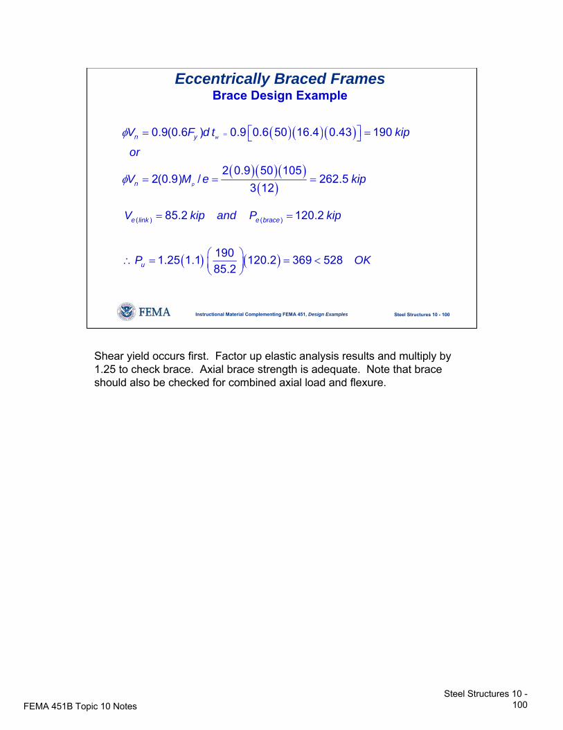
Eccentrically Braced FramesBrace Design Example
( )( )( )
( )( )( )( )
0.9(0.6 ) 0.9 0.6 50 16.4 0.43 190
2 0.9 50 1052(0.9) / 262.5
3 12
w
p
n y
n
V F d t kip
or
V M e kip
φ
φ
= ⎡ ⎤= =⎣ ⎦
= = =
( ) ( )
( ) ( )85.2 120.2
1901.25 1.1 120.2 369 52885.2
e link e brace
u
V kip and P kip
P OK
= =
⎛ ⎞∴ = = <⎜ ⎟⎝ ⎠
Shear yield occurs first. Factor up elastic analysis results and multiply by 1.25 to check brace. Axial brace strength is adequate. Note that brace should also be checked for combined axial load and flexure.
FEMA 451B Topic 10 NotesSteel Structures 10 -
101
Steel Structures 10 - 101Instructional Material Complementing FEMA 451, Design Examples
NEHRP Recommended ProvisionsSteel Design
• Context in NEHRP Recommended Provisions
• Steel behavior
• Reference standards and design strength
• Moment resisting frames
• Braced frames
• Other topics
Table of contents: other topics.
FEMA 451B Topic 10 NotesSteel Structures 10 -
102
Steel Structures 10 - 102Instructional Material Complementing FEMA 451, Design Examples
Special Truss Moment Frame
• Buckling and yieldingin special section
• Design to be elasticoutside special section
• Deforms similar to EBF
• Special panels to be symmetric X orVierendeel
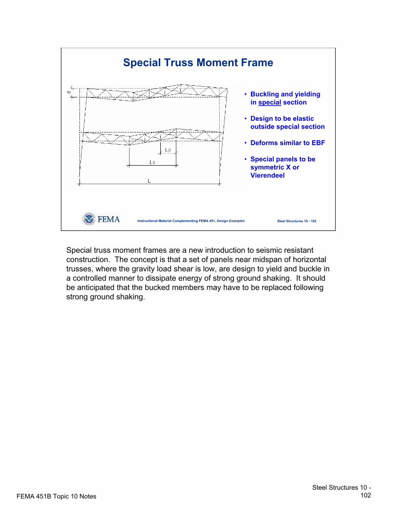
Special truss moment frames are a new introduction to seismic resistant construction. The concept is that a set of panels near midspan of horizontal trusses, where the gravity load shear is low, are design to yield and buckle in a controlled manner to dissipate energy of strong ground shaking. It should be anticipated that the bucked members may have to be replaced following strong ground shaking.
FEMA 451B Topic 10 NotesSteel Structures 10 -
103
Steel Structures 10 - 103Instructional Material Complementing FEMA 451, Design Examples
Special Truss Moment Frame
Geometric Limits:
5.2tb,diagonalsbarFlat
23
dL
32
5.0LL1.0
'6d'65L
p
s
≤
<<
<<
≤≤
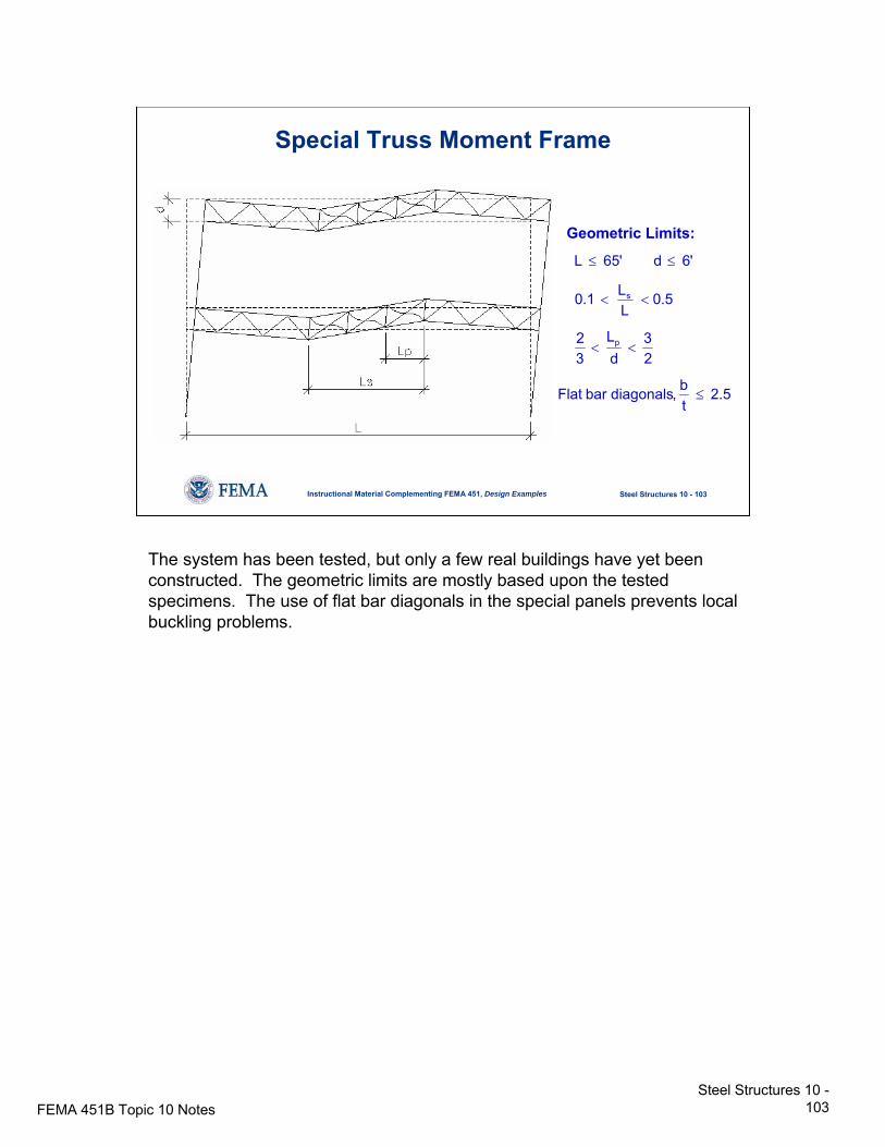
The system has been tested, but only a few real buildings have yet been constructed. The geometric limits are mostly based upon the tested specimens. The use of flat bar diagonals in the special panels prevents local buckling problems.
FEMA 451B Topic 10 NotesSteel Structures 10 -
104
Steel Structures 10 - 104Instructional Material Complementing FEMA 451, Design Examples
Special Truss Moment Frame
( )2
2 sin 0.3pcp nt cd
s
i i p
MV P P
L
F h V L
α⎛ ⎞
= + +⎜ ⎟⎝ ⎠
=∑ ∑
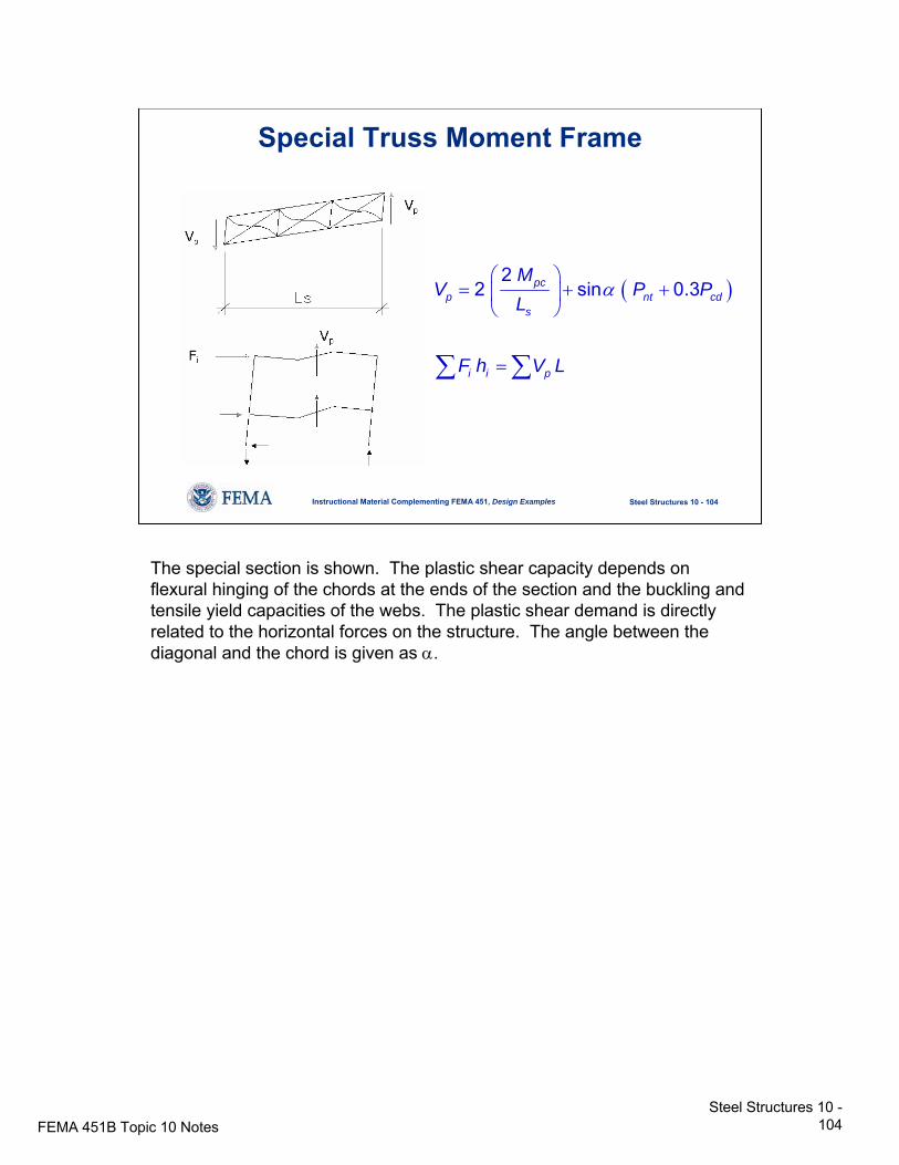
The special section is shown. The plastic shear capacity depends on flexural hinging of the chords at the ends of the section and the buckling and tensile yield capacities of the webs. The plastic shear demand is directly related to the horizontal forces on the structure. The angle between the diagonal and the chord is given as α.
FEMA 451B Topic 10 NotesSteel Structures 10 -
105
Steel Structures 10 - 105Instructional Material Complementing FEMA 451, Design Examples
Special Truss Moment Frame
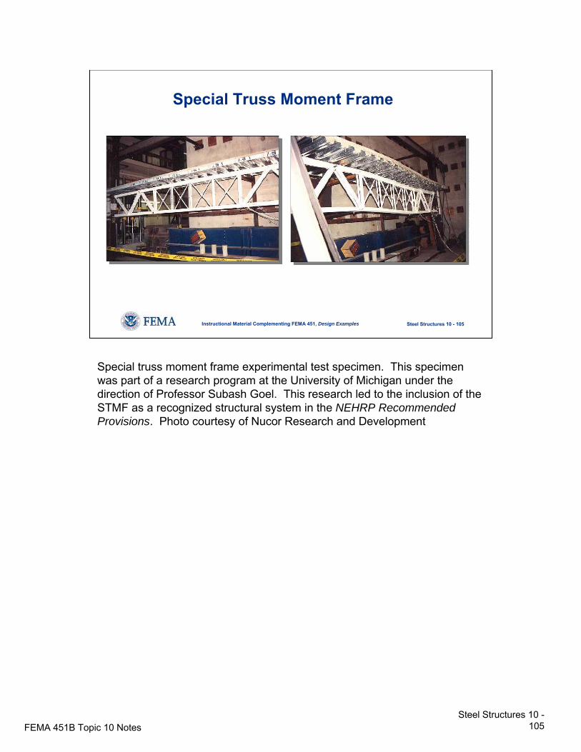
Special truss moment frame experimental test specimen. This specimen was part of a research program at the University of Michigan under the direction of Professor Subash Goel. This research led to the inclusion of the STMF as a recognized structural system in the NEHRP Recommended Provisions. Photo courtesy of Nucor Research and Development
FEMA 451B Topic 10 NotesSteel Structures 10 -
106
Steel Structures 10 - 106Instructional Material Complementing FEMA 451, Design Examples
Special Truss Moment Frame
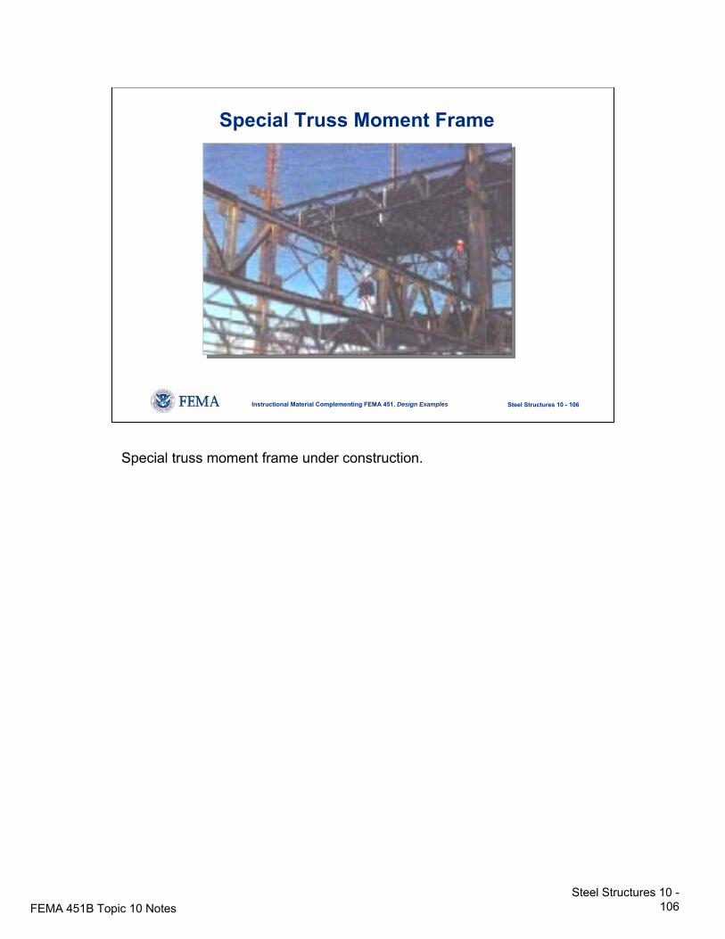
Special truss moment frame under construction.
FEMA 451B Topic 10 NotesSteel Structures 10 -
107
Steel Structures 10 - 107Instructional Material Complementing FEMA 451, Design Examples
General Seismic DetailingMaterials:
• Limit to lower strengths and higher ductilities
Bolted Joints:• Fully tensioned high strength bolts• Limit on bearing
Seismic detailing per AISC Seismic is more than simply the rules for the specific systems. There are also general rules for several subjects that apply to all types of steel seismic resisting systems.
FEMA 451B Topic 10 NotesSteel Structures 10 -
108
Steel Structures 10 - 108Instructional Material Complementing FEMA 451, Design Examples
General Seismic DetailingWelded Joints:
• AWS requirements for welding procedure specs• Filler metal toughness
• CVN > 20 ft-lb @ -20°F, or AISC Seismic App. X• Warning on discontinuities, tack welds, run offs,
gouges, etc.Columns:
• Strength using Ωo if Pu / φPn > 0.4• Splices: Requirements on partial pen welds and
fillet welds
The requirements for weld metal toughness are new. The reference to AWS welding procedure specs is a new emphasis. It is likely that structural engineers will have to become more well educated about welding in the future. The rules on columns are intended to prevent premature failure in these vulnerable components.
FEMA 451B Topic 10 NotesSteel Structures 10 -
109
Steel Structures 10 - 109Instructional Material Complementing FEMA 451, Design Examples
Steel DiaphragmExample
φVn = φ (approved strength)
φ = 0.6
For example only:Use approved strength as 2.0 x working load inSDI Diaphragm Design Manual
This example not in FEMA 451; for example only, use capacities from SDI Diaphragm Design Manual.
FEMA 451B Topic 10 NotesSteel Structures 10 -
110
Steel Structures 10 - 110Instructional Material Complementing FEMA 451, Design Examples
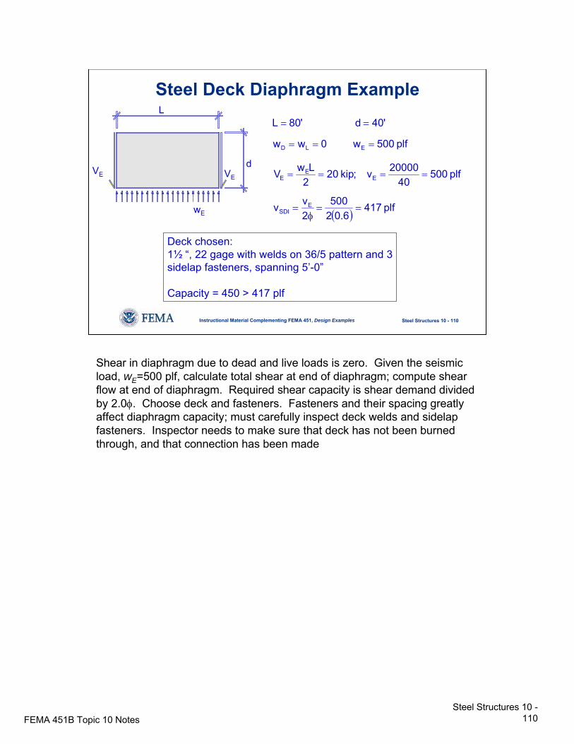
Steel Deck Diaphragm ExampleL
dVE VE
wE
plf500w0ww
'40d'80L
ELD ===
==
( ) plf4176.02
5002vv
plf50040
20000v;kip202LwV
ESDI
EE
E
==φ
=
====
Deck chosen:1½ “, 22 gage with welds on 36/5 pattern and 3sidelap fasteners, spanning 5’-0”
Capacity = 450 > 417 plf
Shear in diaphragm due to dead and live loads is zero. Given the seismic load, wE=500 plf, calculate total shear at end of diaphragm; compute shear flow at end of diaphragm. Required shear capacity is shear demand divided by 2.0φ. Choose deck and fasteners. Fasteners and their spacing greatly affect diaphragm capacity; must carefully inspect deck welds and sidelapfasteners. Inspector needs to make sure that deck has not been burned through, and that connection has been made
FEMA 451B Topic 10 NotesSteel Structures 10 -
111
Steel Structures 10 - 111Instructional Material Complementing FEMA 451, Design Examples
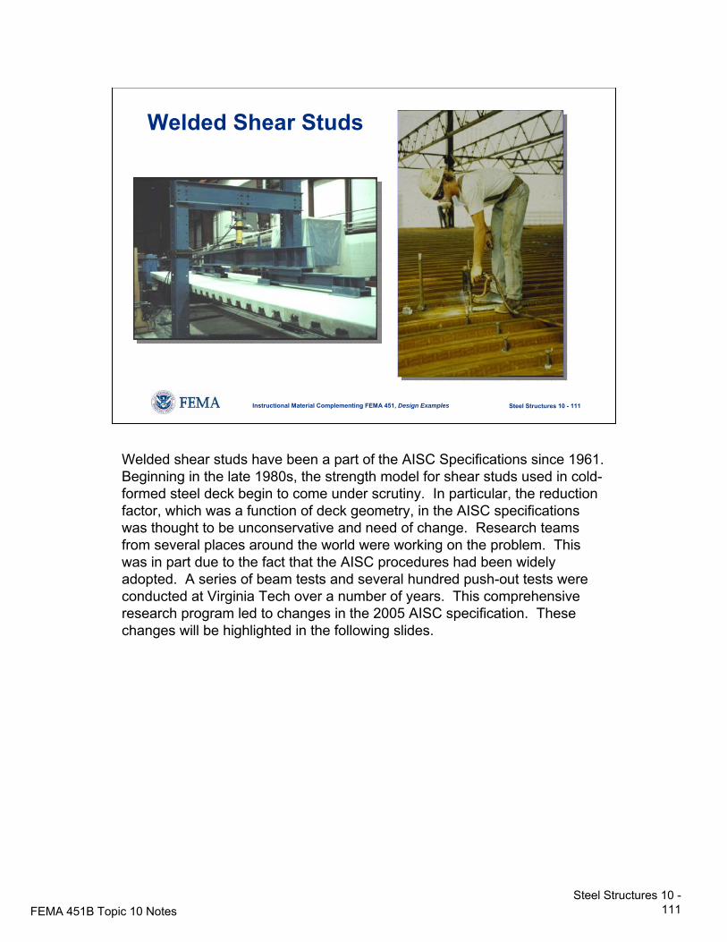
Welded Shear Studs
Welded shear studs have been a part of the AISC Specifications since 1961. Beginning in the late 1980s, the strength model for shear studs used in cold-formed steel deck begin to come under scrutiny. In particular, the reduction factor, which was a function of deck geometry, in the AISC specifications was thought to be unconservative and need of change. Research teams from several places around the world were working on the problem. This was in part due to the fact that the AISC procedures had been widely adopted. A series of beam tests and several hundred push-out tests were conducted at Virginia Tech over a number of years. This comprehensive research program led to changes in the 2005 AISC specification. These changes will be highlighted in the following slides.
FEMA 451B Topic 10 NotesSteel Structures 10 -
112
Steel Structures 10 - 112Instructional Material Complementing FEMA 451, Design Examples
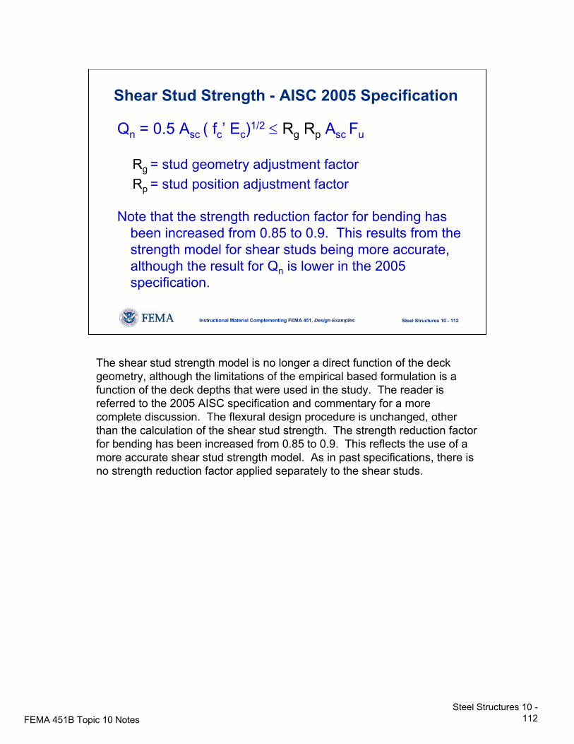
Shear Stud Strength - AISC 2005 Specification
Qn = 0.5 Asc ( fc’ Ec)1/2 ≤ Rg Rp Asc Fu
Rg = stud geometry adjustment factorRp = stud position adjustment factor
Note that the strength reduction factor for bending has been increased from 0.85 to 0.9. This results from the strength model for shear studs being more accurate, although the result for Qn is lower in the 2005 specification.
The shear stud strength model is no longer a direct function of the deck geometry, although the limitations of the empirical based formulation is a function of the deck depths that were used in the study. The reader is referred to the 2005 AISC specification and commentary for a more complete discussion. The flexural design procedure is unchanged, other than the calculation of the shear stud strength. The strength reduction factor for bending has been increased from 0.85 to 0.9. This reflects the use of a more accurate shear stud strength model. As in past specifications, there is no strength reduction factor applied separately to the shear studs.
FEMA 451B Topic 10 NotesSteel Structures 10 -
113
Steel Structures 10 - 113Instructional Material Complementing FEMA 451, Design Examples
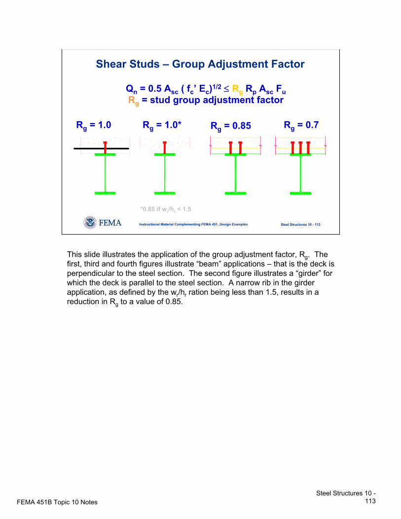
Rg = 1.0 Rg = 1.0* Rg = 0.85 Rg = 0.7
Shear Studs – Group Adjustment Factor
*0.85 if wr/hr < 1.5
Qn = 0.5 Asc ( fc’ Ec)1/2 ≤ Rg Rp Asc FuRg = stud group adjustment factor
This slide illustrates the application of the group adjustment factor, Rg. The first, third and fourth figures illustrate “beam” applications – that is the deck is perpendicular to the steel section. The second figure illustrates a “girder” for which the deck is parallel to the steel section. A narrow rib in the girder application, as defined by the wr/hr ration being less than 1.5, results in a reduction in Rg to a value of 0.85.
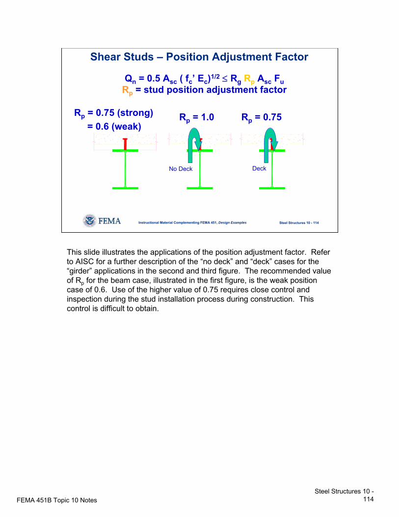
FEMA 451B Topic 10 NotesSteel Structures 10 -
114
Steel Structures 10 - 114Instructional Material Complementing FEMA 451, Design Examples
Shear Studs – Position Adjustment Factor
Rp = 0.75 (strong)= 0.6 (weak)
Rp = 1.0 Rp = 0.75
DeckNo Deck
Qn = 0.5 Asc ( fc’ Ec)1/2 ≤ Rg Rp Asc FuRp = stud position adjustment factor
This slide illustrates the applications of the position adjustment factor. Refer to AISC for a further description of the “no deck” and “deck” cases for the “girder” applications in the second and third figure. The recommended value of Rp for the beam case, illustrated in the first figure, is the weak position case of 0.6. Use of the higher value of 0.75 requires close control and inspection during the stud installation process during construction. This control is difficult to obtain.
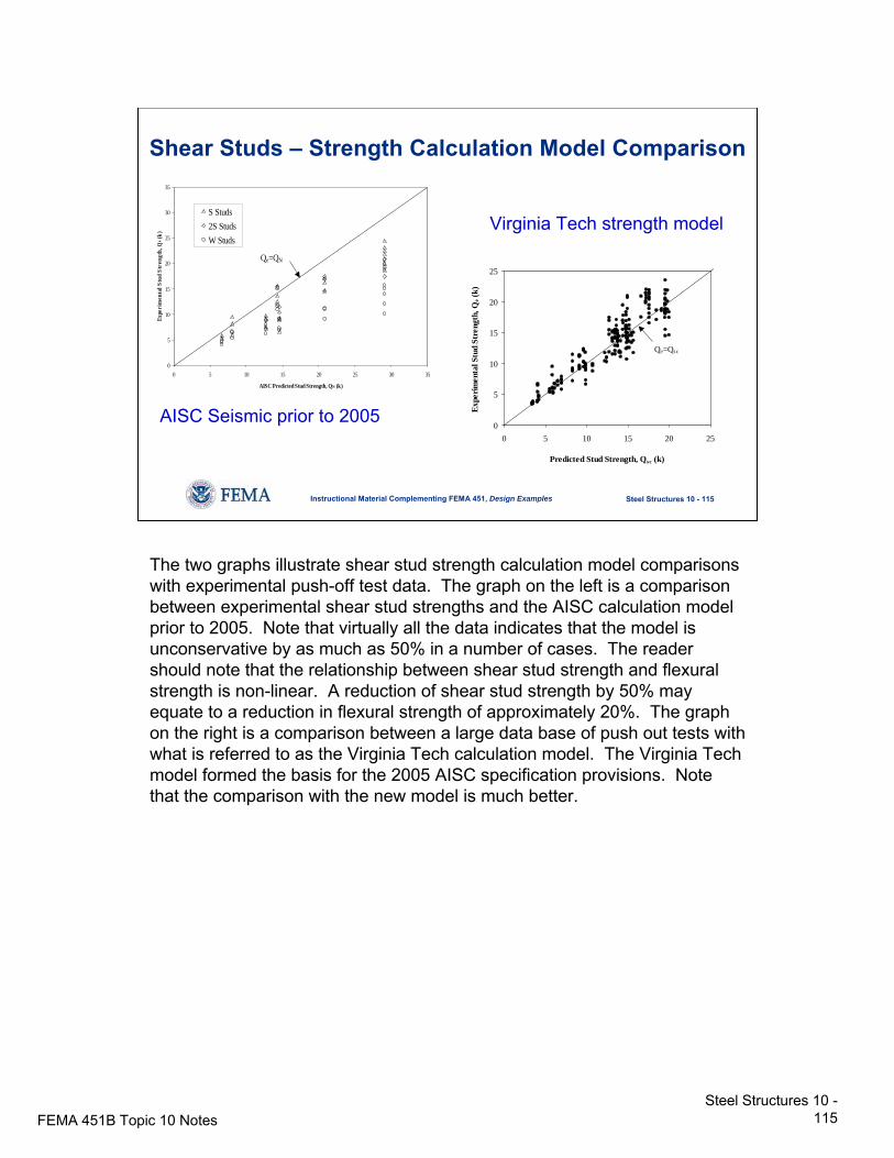
FEMA 451B Topic 10 NotesSteel Structures 10 -
115
Steel Structures 10 - 115Instructional Material Complementing FEMA 451, Design Examples
Shear Studs – Strength Calculation Model Comparison
0
5
10
15
20
25
30
35
0 5 10 15 20 25 30 35
AISC Predicted Stud Strength, QN (k)
Expe
rim
enta
l Stu
d St
reng
th, Q
e (k)
S Studs2S StudsW Studs
Qe=QN
0
5
10
15
20
25
0 5 10 15 20 25
Predicted Stud Strength, Qsc (k)
Expe
rimen
tal S
tud
Stre
ngth
, Qe (
k)
Qe=Qsc
AISC Seismic prior to 2005
Virginia Tech strength model
The two graphs illustrate shear stud strength calculation model comparisons with experimental push-off test data. The graph on the left is a comparison between experimental shear stud strengths and the AISC calculation model prior to 2005. Note that virtually all the data indicates that the model is unconservative by as much as 50% in a number of cases. The reader should note that the relationship between shear stud strength and flexural strength is non-linear. A reduction of shear stud strength by 50% may equate to a reduction in flexural strength of approximately 20%. The graph on the right is a comparison between a large data base of push out tests with what is referred to as the Virginia Tech calculation model. The Virginia Tech model formed the basis for the 2005 AISC specification provisions. Note that the comparison with the new model is much better.
FEMA 451B Topic 10 NotesSteel Structures 10 -
116
Steel Structures 10 - 116Instructional Material Complementing FEMA 451, Design Examples
Shear Studs – Diaphragm Applications
Shear studs are often used along diaphragm collector members to transfer the shear from the slab into the frame. The shear stud calculation model in the 2005 AISC specification can be used to compute the nominal shear strengths. A strength reduction factor should be used when comparing these values to the factored shear. There is no code-established value for the strength reduction factor. A value of 0.8 is recommended pending further development.
Text in slide is self-explanatory and requires no further comment.
FEMA 451B Topic 10 NotesSteel Structures 10 -
117
Steel Structures 10 - 117Instructional Material Complementing FEMA 451, Design Examples
Inspection and TestingInspection Requirements
• Welding:- Single pass fillet or resistance welds
> PERIODIC- All other welds
> CONTINUOUS
• High strength bolts:> PERIODIC
Inspection requirements: Periodic inspection of single pass fillet welds and continuous inspection of all other welds. AWS D1.1 is a good reference for what items should be noted during inspection of welding. Additional inspection methods include ultrasonic inspection, x-ray inspection, and other non-destructive methods. High strength bolts must be periodically inspected.
FEMA 451B Topic 10 NotesSteel Structures 10 -
118
Steel Structures 10 - 118Instructional Material Complementing FEMA 451, Design Examples
Inspection and TestingShop Certification
• Domestic:- AISC- Local jurisdictions
• Foreign:- No established international criteria
AISC can certify fabricating shops. Program includes scheduled and surprise inspections to review quality control procedures, personnel, and results. Some local jurisdictions have adopted similar certification procedures. As there is no internationally accepted quality certification, foreign fabricated steel should be given close inspection.
FEMA 451B Topic 10 NotesSteel Structures 10 -
119
Steel Structures 10 - 119Instructional Material Complementing FEMA 451, Design Examples
Inspection and TestingBase Metal Testing
• More than 1-1/2 inches thick
• Subjected to through-thickness weld shrinkage
• Lamellar tearing
• Ultrasonic testing
Base metal testing required: where base metal more than 1-1/2 in. thick subjected to through-thickness weld shrinkage (lamellar tearing is possible); ultrasonic testing required to identify presence of discontinuities in base metal.
FEMA 451B Topic 10 NotesSteel Structures 10 -
120
Steel Structures 10 - 120Instructional Material Complementing FEMA 451, Design Examples
NEHRP Recommended ProvisionsSteel Design
• Context in Provisions
• Steel behavior
• Reference standards and design strength
• Moment resisting frames
• Braced frames
• Other topics
• Summary
Summary