
Top Drive
1128
EXI TOP DRIVE SYSTEM 350/400 TON EXI 600HP MANUAL
-
Upload
franklin-jose-almera-acosta -
Category
Documents
-
view
686 -
download
32
Transcript of Top Drive

EXI TOP DRIVE SYSTEM
350/400 TON EXI 600HP
MANUAL

EXI TOP DRIVE SYSTEM
350/400 TON EXI 600HP
MANUAL INDEX
TITLE
SECTION
System Description
1
Installation Guide
2
Operations Guide
3
Maintenance Guide
4
Electrical Troubleshooting Guide
5
List of Parts and Assemblies
6
Electrical Drawings
7
Hydraulic Schematic
8
Specification – Hydraulic Fluid
9
Hi-Kalibre Actuator Manual
10

System Description
EXI Top Drive System
350/400TON EXI 600HP
DOCUMENT NAME: 880076 REV 2


COPYRIGHT AND DISCLAIMER SYSTEM DESCRIPTION
Tesco Corporation ("TESCO") has made every effort to ensure that this document contains accurate and current information for the TESCO top drive, however, the document is intended to be used in conjunction with a complete training program and on-site supervision and TESCO does not warrant or guarantee that the information contained herein is either complete or accurate in every respect, and the reader hereby protects, indemnifies and holds harmless Tesco Corporation together with its directors, officers, employees and agents from and against all liability for personal injury, death or property damage to any person arising directly or indirectly from the use by the reader of the information contained in the document.
This equipment was filled at the factory with TESCO ULTREX™ brand fluids and greases. To ensure maximum performance and to avoid cross-contamination, we strongly recommend the continued usage of TESCO ULTREX™ lubricants, unless otherwise specified.
TESCO ULTREX™ is a trademark and TESCO® is a registered trademark of Tesco Corporation.
Tesco Corporation © 2009
Contact Information
Corporate Head Office3993 W. Sam Houston Parkway No., Suite 100
Houston, Texas, 77043USA
www.tescocorp.comwww.tescoparts.com
Telephone: (713) 359-7000Fax: (713) 359-7001
After Market Sales and Service ContactToll Free North America: 1-877-TESCO-77
International: 713-359-7295
CONTACT: 1-877-TESCO-77 350/400 TON EXI 600HP WWW.TESCOCORP.COM
INTL: 713-359-7295 I WWW.TESCOPARTS.COM

REVISION INFORMATION SYSTEM DESCRIPTION
Revision Information
Version Date Description of Changes
0 August 2007 First release of document
1 October 2008 Upgrade 350 EXI 600 to 350/400 EXI 600
2 September 2009 Added TESCO ULTREX™ recommendations and updated the footer to contain contact information.
CONTACT: 1-877-TESCO-77 350/400 TON EXI 600HP WWW.TESCOCORP.COM
INTL: 713-359-7295 II WWW.TESCOPARTS.COM

TABLE OF CONTENTS SYSTEM DESCRIPTION
TABLE OF CONTENTS
SAFETY INSTRUCTIONS . . . . . . . . . . . . . . . . . . . . . . . . . . . . . . . . . . . . . . . . . . . . . . . . . V
CHAPTER 1: ABOUT THIS DOCUMENT . . . . . . . . . . . . . . . . . . . . . . . . . . . . . . . . . . . . . . 1
CHAPTER 2: TOP DRIVE SYSTEM DESCRIPTION . . . . . . . . . . . . . . . . . . . . . . . . . . . . . . . 3
Introduction and General Specifications . . . . . . . . . . . . . . . . . . . . . . . . . . . . . . . . . . . . . . . . . . . . . . 3
Top Drive Components. . . . . . . . . . . . . . . . . . . . . . . . . . . . . . . . . . . . . . . . . . . . . . . . . . . . . . . . . . . . . 6
Gearbox . . . . . . . . . . . . . . . . . . . . . . . . . . . . . . . . . . . . . . . . . . . . . . . . . . . . . . . . . . . . . . . . . . . . . . 8
Load Collar and Load Nut. . . . . . . . . . . . . . . . . . . . . . . . . . . . . . . . . . . . . . . . . . . . . . . . . . . . . . . . . 8
Mudsaver Valve . . . . . . . . . . . . . . . . . . . . . . . . . . . . . . . . . . . . . . . . . . . . . . . . . . . . . . . . . . . . . . . . 8
Pipe Handler. . . . . . . . . . . . . . . . . . . . . . . . . . . . . . . . . . . . . . . . . . . . . . . . . . . . . . . . . . . . . . . . . . . 8
Counter-Balance. . . . . . . . . . . . . . . . . . . . . . . . . . . . . . . . . . . . . . . . . . . . . . . . . . . . . . . . . . . . . . . . 8
Top Drive Power Supply. . . . . . . . . . . . . . . . . . . . . . . . . . . . . . . . . . . . . . . . . . . . . . . . . . . . . . . . . . 9
Travel Stand . . . . . . . . . . . . . . . . . . . . . . . . . . . . . . . . . . . . . . . . . . . . . . . . . . . . . . . . . . . . . . . . . . . 9
Power Module . . . . . . . . . . . . . . . . . . . . . . . . . . . . . . . . . . . . . . . . . . . . . . . . . . . . . . . . . . . . . . . . . . . . 9
Main Panel . . . . . . . . . . . . . . . . . . . . . . . . . . . . . . . . . . . . . . . . . . . . . . . . . . . . . . . . . . . . . . . . . . . . 9
600V Distribution Panel . . . . . . . . . . . . . . . . . . . . . . . . . . . . . . . . . . . . . . . . . . . . . . . . . . . . . . . . . . 9
15KVA 600: 208/120V transformer. . . . . . . . . . . . . . . . . . . . . . . . . . . . . . . . . . . . . . . . . . . . . . . . . . 9
120/208V Distribution Panel . . . . . . . . . . . . . . . . . . . . . . . . . . . . . . . . . . . . . . . . . . . . . . . . . . . . . . . 9
Drive and Building Cooling . . . . . . . . . . . . . . . . . . . . . . . . . . . . . . . . . . . . . . . . . . . . . . . . . . . . . . . . 9
Auxiliary Hydraulic Power Unit . . . . . . . . . . . . . . . . . . . . . . . . . . . . . . . . . . . . . . . . . . . . . . . . . . . . . 10
Torque Arrest System. . . . . . . . . . . . . . . . . . . . . . . . . . . . . . . . . . . . . . . . . . . . . . . . . . . . . . . . . . . . . 11
Torque Bushing . . . . . . . . . . . . . . . . . . . . . . . . . . . . . . . . . . . . . . . . . . . . . . . . . . . . . . . . . . . . . . . 11
Extend Frame and Extend Arms . . . . . . . . . . . . . . . . . . . . . . . . . . . . . . . . . . . . . . . . . . . . . . . . . . 11
Torque Track . . . . . . . . . . . . . . . . . . . . . . . . . . . . . . . . . . . . . . . . . . . . . . . . . . . . . . . . . . . . . . . . . 11
Torque Beam and T-bar . . . . . . . . . . . . . . . . . . . . . . . . . . . . . . . . . . . . . . . . . . . . . . . . . . . . . . . . . 11
Service Loop . . . . . . . . . . . . . . . . . . . . . . . . . . . . . . . . . . . . . . . . . . . . . . . . . . . . . . . . . . . . . . . . . . . . 13
Electrical Cables. . . . . . . . . . . . . . . . . . . . . . . . . . . . . . . . . . . . . . . . . . . . . . . . . . . . . . . . . . . . . . . 14
Hydraulic Hoses . . . . . . . . . . . . . . . . . . . . . . . . . . . . . . . . . . . . . . . . . . . . . . . . . . . . . . . . . . . . . . . 14
Driller’s Panel . . . . . . . . . . . . . . . . . . . . . . . . . . . . . . . . . . . . . . . . . . . . . . . . . . . . . . . . . . . . . . . . . . . 14
Safety Interlocks . . . . . . . . . . . . . . . . . . . . . . . . . . . . . . . . . . . . . . . . . . . . . . . . . . . . . . . . . . . . . . . . . 15
Emergency Shut Down (E.S.D.) . . . . . . . . . . . . . . . . . . . . . . . . . . . . . . . . . . . . . . . . . . . . . . . . . . . 15
Air interlocks . . . . . . . . . . . . . . . . . . . . . . . . . . . . . . . . . . . . . . . . . . . . . . . . . . . . . . . . . . . . . . . . . . 15
Shipping Containers . . . . . . . . . . . . . . . . . . . . . . . . . . . . . . . . . . . . . . . . . . . . . . . . . . . . . . . . . . . . . . 17
Container 1 . . . . . . . . . . . . . . . . . . . . . . . . . . . . . . . . . . . . . . . . . . . . . . . . . . . . . . . . . . . . . . . . . . . 17
Container 2 . . . . . . . . . . . . . . . . . . . . . . . . . . . . . . . . . . . . . . . . . . . . . . . . . . . . . . . . . . . . . . . . . . . 17
Container 3 . . . . . . . . . . . . . . . . . . . . . . . . . . . . . . . . . . . . . . . . . . . . . . . . . . . . . . . . . . . . . . . . . . . 17
CONTACT: 1-877-TESCO-77 350/400 TON EXI 600HP WWW.TESCOCORP.COM
INTL: 713-359-7295 III WWW.TESCOPARTS.COM

SYSTEM DESCRIPTION TABLE OF CONTENTS
Options . . . . . . . . . . . . . . . . . . . . . . . . . . . . . . . . . . . . . . . . . . . . . . . . . . . . . . . . . . . . . . . . . . . . . . . . .18
Elevators and Elevator Links. . . . . . . . . . . . . . . . . . . . . . . . . . . . . . . . . . . . . . . . . . . . . . . . . . . . . .18
Additional Safety Valve and Actuator . . . . . . . . . . . . . . . . . . . . . . . . . . . . . . . . . . . . . . . . . . . . . . .18
Subs . . . . . . . . . . . . . . . . . . . . . . . . . . . . . . . . . . . . . . . . . . . . . . . . . . . . . . . . . . . . . . . . . . . . . . . .18
Grabber Drill Pipe Guides . . . . . . . . . . . . . . . . . . . . . . . . . . . . . . . . . . . . . . . . . . . . . . . . . . . . . . . .18
Rotary Table Stabilizer Bushings . . . . . . . . . . . . . . . . . . . . . . . . . . . . . . . . . . . . . . . . . . . . . . . . . .18
Rotary Hose and Standpipe Extension . . . . . . . . . . . . . . . . . . . . . . . . . . . . . . . . . . . . . . . . . . . . . .18
Torque Arrest System . . . . . . . . . . . . . . . . . . . . . . . . . . . . . . . . . . . . . . . . . . . . . . . . . . . . . . . . . . .18
Alarms . . . . . . . . . . . . . . . . . . . . . . . . . . . . . . . . . . . . . . . . . . . . . . . . . . . . . . . . . . . . . . . . . . . . . . .18
Driller’s Panel . . . . . . . . . . . . . . . . . . . . . . . . . . . . . . . . . . . . . . . . . . . . . . . . . . . . . . . . . . . . . . . . .19
Power Supply Options. . . . . . . . . . . . . . . . . . . . . . . . . . . . . . . . . . . . . . . . . . . . . . . . . . . . . . . . . . .19
Other Available Options . . . . . . . . . . . . . . . . . . . . . . . . . . . . . . . . . . . . . . . . . . . . . . . . . . . . . . . . .19
CONTACT: 1-877-TESCO-77 350/400 TON EXI 600HP WWW.TESCOCORP.COM
INTL: 713-359-7295 IV WWW.TESCOPARTS.COM

SAFETY INSTRUCTIONS SYSTEM DESCRIPTION
SAFETY INSTRUCTIONS
Warning! Before operating and servicing this top drive system, always read and follow all safety instructions such as the warnings and cautions mentioned below and throughout the manual.
Top Drive System users risk injury to themselves and to others if the top drive is used improperly and/or safety precautions are not followed. TESCO advises personnel who work with or near the equipment to always wear proper personal protective equipment (PPE). Proper PPE consists of, but is not limited to, the following:
• hearing protection (ear defenders)• hard hat• safety glasses• steel toe shoes• fall protection when working above 6.5 ft (2 m), or the minimum height
requirement as directed by local jurisdiction.
Caution: This equipment is designed and certified for use in a hazardous environment. When maintenance requires replacement of parts, only identical parts can be used. Using alternate, non-iden-tical parts as a substitution may void compliance and certification.
Caution: Always perform the correct lock-out procedures as recommended by the Safety or Loss Prevention department before implementing maintenance.
Caution: Only authorized personnel can operate the top drive system.
Caution: This equipment can generate noise up to 90 decibels. Hearing protection suitable for this noise level must be worn when operating this equipment.
!
!
!
!
!
CONTACT: 1-877-TESCO-77 350/400 TON EXI 600HP WWW.TESCOCORP.COM
INTL: 713-359-7295 V WWW.TESCOPARTS.COM

SYSTEM DESCRIPTION SAFETY INSTRUCTIONS
Warning! Electrical voltages of different potentials are used throughout the TESCO top drive components (600 VAC, 208 VAC, 120 VAC, 840 VDC, 5-24 VDC). It is imperative that only qualified personnel install, maintain and/or troubleshoot the electrical systems. A severe hazard exists to personnel not accustomed to, or familiar with, electrical hazards and procedures.
Warning! There are high voltage capacitors installed in the ACS800 drive module. It is imperative that at least 5 minutes elapse, after power to the drive has been turned off, before any testing or repairs be undertaken at the module. The capacitors require time to ‘drain’ their stored electrical energy.
Warning! Accumulators used in the auxiliary hydraulic system are under the pressure of gas. Release this pressure before any maintenance is done on the auxiliary hydraulic system.
!
!
!
CONTACT: 1-877-TESCO-77 350/400 TON EXI 600HP WWW.TESCOCORP.COM
INTL: 713-359-7295 VI WWW.TESCOPARTS.COM

CHAPTER 1: ABOUT THIS DOCUMENT SYSTEM DESCRIPTION
CHAPTER 1: ABOUT THIS DOCUMENT
This document contains a description of the major components of the Electric Integrated Top Drive System with integrated quill.
A complete EXI Top Drive System consists of the following:
• top drive• power module (drive building)• auxiliary hydraulic power unit • interconnecting service loop and reel• torque arrest system• associated buildings, containers, and equipment
This document provides a brief description of each major component, as well as a list of available spares and options.
Important Note: Illustrations contained herein are provided for reference purposes only, equipment shown may differ from the actual unit appearance.
Table 1-1: Where to find more information
For information on Refer to
• installation• rig up• commissioning• pre-operational checklists• rig out procedures
Installation Guide
• setting torque and speed• driller's panel functions and operating descriptions• making connections• drilling ahead• tripping• freeing stuck pipe
Operations Guide
• load path inspections• maintenance/service schedules• component disassembly and reassembly
Maintenance Guide
TESCO manufactured parts and part numbers Parts List
troubleshooting Troubleshooting Guide (where available)
• electrical schematics• hydraulic schematics• gearbox lubrication schematics
System schematics
available options and spares TESCO representative
CONTACT: 1-877-TESCO-77 350/400 TON EXI 600HP WWW.TESCOCORP.COM
INTL: 713-359-7295 1 WWW.TESCOPARTS.COM

SYSTEM DESCRIPTION CHAPTER 1: ABOUT THIS DOCUMENT
This page has been left blank intentionally.
CONTACT: 1-877-TESCO-77 350/400 TON EXI 600HP WWW.TESCOCORP.COM
INTL: 713-359-7295 2 WWW.TESCOPARTS.COM

CHAPTER 2: TOP DRIVE SYSTEM DESCRIPTION SYSTEM DESCRIPTION
CHAPTER 2: TOP DRIVE SYSTEM DESCRIPTION
INTRODUCTION AND GENERAL SPECIFICATIONS
The TESCO EXI Top Drive System is a compact, full featured top drive, designed for use on land-based drilling rigs with narrow masts.
The EXI Top Drive System features an AC induction motor and variable frequency drive system. The EXI Top Drive System can be operated from a self-contained generator, or connected directly to the rig’s AC Bus (600 VAC - 50 or 60 cycle).
Figure 2-1: 350 EXI 600 Top Drive, shown w/ pipe guard, counterbalance system and travel stand
CONTACT: 1-877-TESCO-77 350/400TON EXI 600HP WWW.TESCOCORP.COM
INTL: 713-359-7295 3 WWW.TESCOPARTS.COM

SYSTEM DESCRIPTION CHAPTER 2: TOP DRIVE SYSTEM DESCRIPTION
Metric unit conversions (in brackets) have been provided for convenience only. All product specifications use the original imperial units unless indicated otherwise.
All weight values are approximate.
Figure 2-2: 400 EXI 600 Top Drive, shown w/ pipe guard, counterbalance system and travel stand
Table 2-1: EXI Top Drive System specifications
Imperial Metric
Rated capacity through load collar 350/400 Ton 318/363 tonne
Rated horsepower 600 hp 448 kW
Max. continous drill torque 30,000 ft-lb 4 067 daN-m
Make-up/Breakout torque 45,000 ft-lb 6 101 daN-m
Max. speed 220 RPM
Weight of the top drive plus:• elevators• elevator links• counterbalance system
25,000 lb 11 340 kg
Length (250T, with 9 ft links) 237 in. 6.02 m
Width 48 in. 1.23 m
Quill connection NC61 SRG
Hazardous area certification CSA Class 1 Div II or II 2 G
CONTACT: 1-877-TESCO-77 350/400TON EXI 600HP WWW.TESCOCORP.COM
INTL: 713-359-7295 4 WWW.TESCOPARTS.COM
CHAPTER 2: TOP DRIVE SYSTEM DESCRIPTION SYSTEM DESCRIPTION
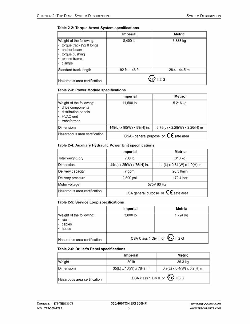
Table 2-2: Torque Arrest System specifications
Imperial Metric
Weight of the following:• torque track (92 ft long)• anchor beam• torque bushing• extend frame• clamps
8,400 lb 3,833 kg
Standard track length 92 ft - 146 ft 28.4 - 44.5 m
Hazardous area certification II 2 G
Table 2-3: Power Module specifications
Imperial Metric
Weight of the following:• drive components• distribution panels• HVAC unit• transformer
11,500 lb 5 216 kg
Dimensions 149(L) x 90(W) x 89(H) in. 3.78(L) x 2.29(W) x 2.26(H) m
Hazaradous area certificationCSA - general purpose or safe area
Table 2-4: Auxiliary Hydraulic Power Unit specifications
Imperial Metric
Total weight, dry 700 lb (318 kg)
Dimensions 44(L) x 25(W) x 75(H) in. 1.1(L) x 0.64(W) x 1.9(H) m
Delivery capacity 7 gpm 26.5 l/min
Delivery pressure 2,500 psi 172.4 bar
Motor voltage 575V 60 Hz
Hazardous area certificationCSA general purpose or safe area
Table 2-5: Service Loop specifications
Imperial Metric
Weight of the following:• reels• cables• hoses
3,800 lb 1 724 kg
Hazardous area certification CSA Class 1 Div II or II 2 G
Table 2-6: Driller’s Panel specifications
Imperial Metric
Weight 80 lb 36.3 kg
Dimensions 35(L) x 16(W) x 7(H) in. 0.9(L) x 0.4(W) x 0.2(H) m
Hazardous area certification CSA class 1 Div II or II 3 G
CONTACT: 1-877-TESCO-77 350/400TON EXI 600HP WWW.TESCOCORP.COM
INTL: 713-359-7295 5 WWW.TESCOPARTS.COM

SYSTEM DESCRIPTION CHAPTER 2: TOP DRIVE SYSTEM DESCRIPTION
TOP DRIVE COMPONENTS
Figure 2-3: 350 EXI 600 Top Drive System General Assembly
CONTACT: 1-877-TESCO-77 350/400TON EXI 600HP WWW.TESCOCORP.COM
INTL: 713-359-7295 6 WWW.TESCOPARTS.COM

CHAPTER 2: TOP DRIVE SYSTEM DESCRIPTION SYSTEM DESCRIPTION
Figure 2-4: 400 EXI 600 Top Drive System General Assembly
CONTACT: 1-877-TESCO-77 350/400TON EXI 600HP WWW.TESCOCORP.COM
INTL: 713-359-7295 7 WWW.TESCOPARTS.COM

SYSTEM DESCRIPTION CHAPTER 2: TOP DRIVE SYSTEM DESCRIPTION
Gearbox
• The gearbox is designed for long life and easy service. It supports the 600 hp AC induction motor.
• The gearbox contains the main swivel bearing and all gearing required to drive the quill. The gearbox uses a forced lubrication system with on-board cooling, which is activated by monitoring gearbox oil temperature.
• The temperature of the induction motor is monitored using embedded RTDs in the motor windings. Motor cooling is accomplished with a dedicated blower, which is activated at a pre-determined motor temperature.
Load Collar and Load Nut
The load collar and load nut transfer loads from the elevator links to the quill.
Mudsaver Valve
The mudsaver valve is a double-ball crank valve that acts as a mudsaver. It replaces the upper and lower Kelly cocks. The valve does not descend below the rotary table, except in emergency situations, and it is always easily accessible. The mudsaver valve actuator is operated remotely from the driller’s panel.
Caution: The remotely actuated upper ball valve is not for well control; it functions solely as a mudsaver. The manual operating lower valve is for well control. Ensure that the valve selected can fit into the existing casing.
Pipe Handler
The pipe handling abilities of the EXI Top Drive System include the following:
• Pipe Handler Rotation: The EXI pipe handler rotate mechanism, powered by a single hydraulic motor, provides 360° rotation and can be locked into any orientation. This locking feature can be used to resolve grabber torque when making or breaking connections.
• Elevator Link Tilt Cylinders: These allow extension and retraction of the elevators 35° forward from the vertical position and 55° backward from the vertical position. The link tilt cylinders (actuators) are painted red to clearly identify them.
• Grabber (back-up wrench): The grabber acts as a back-up tong for making or breaking connections at any point in the mast. The grabber will accommodate tool joints from 3-1/8 in. to 8-3/4 in OD.
Note: For tool joints smaller than 4-3/4 in. O.D., non-standard dies or a shim kit must be installed. Grabber intensifier pressures must also be adjusted when smaller OD pipe is used.
Counter-Balance
The top drive features an automatic thread feed compensation to prevent thread damages during make up and break out operations.
!
CONTACT: 1-877-TESCO-77 350/400TON EXI 600HP WWW.TESCOCORP.COM
INTL: 713-359-7295 8 WWW.TESCOPARTS.COM

CHAPTER 2: TOP DRIVE SYSTEM DESCRIPTION SYSTEM DESCRIPTION
Top Drive Power Supply
The top drive motor is powered by a variable frequency drive system, which is located in the power module. All top drive robotic functions are fluid powered by an auxiliary hydraulic system electrically controlled using 24 VDC via the PLC control.
Travel Stand
The top drive is shipped in its own travel stand (handling frame). This frame allows the top drive to be transported and handled using standard rig moving equipment.
POWER MODULE
All electrical distribution and control components are contained within a single walk-in enclosure referred to as the power module.
ACS800 Electric Drive System
The ACS800 electric drive is a modular unit comprised of four main sections: a main breaker and control cabinet, a diode supply unit, two inverter modules, and a dynamic braking unit. The main breaker is rated for 1000A and features an undervoltage trip circuit, which is tied directly to the ESD control on the driller’s panel. The dynamic brake is connected to a grid resistor, which is mounted on the rear outside wall of the power module.
Main Panel
This panel provides the interface between the main PLC, the Driller’s Panel, and sensor information from the Top Drive Panel. The main PLC also communicates with the drive via serial link RS485. Information and commands are processed and distributed to the relevant components.
600V Distribution Panel
This panel contains main breakers for 120/208V power distribution and hydraulic tank heater. It also houses motor starters for the motor and drive blower and for the auxiliary hydraulic pump.
15KVA 600: 208/120V transformer
The transformer is for 208/120V power distribution.
120/208V Distribution Panel
This panel houses breakers for AC/DC control power supply, motor heater, building lighting, and air conditioning.
Drive and Building Cooling
Drive system is air-cooled by a separate blower motor. The temperature of the whole building can be regulated by a 5 ton HVAC (heating, ventilation, and air conditioning) system, which regulates the temperature inside the power module via a programmable thermostat.
CONTACT: 1-877-TESCO-77 350/400TON EXI 600HP WWW.TESCOCORP.COM
INTL: 713-359-7295 9 WWW.TESCOPARTS.COM

SYSTEM DESCRIPTION CHAPTER 2: TOP DRIVE SYSTEM DESCRIPTION
AUXILIARY HYDRAULIC POWER UNIT
The hydraulic power unit consists of:
• an oil reservoir (40 gallons; 151.4 liters),• a gear pump (7 gpm; 26.5 liters/minute), which is coupled to a• 10 hp (7.46 kW) electric motor, and• all necessary piping and control features.
Basic control circuitry for the hydraulic system is mounted on the top drive. The auxiliary system operates at 2,300 psi (15 858 kPa) at the pump level.
Figure 2-5: Auxiliary Hydraulic Power Unit
CONTACT: 1-877-TESCO-77 350/400TON EXI 600HP WWW.TESCOCORP.COM
INTL: 713-359-7295 10 WWW.TESCOPARTS.COM

CHAPTER 2: TOP DRIVE SYSTEM DESCRIPTION SYSTEM DESCRIPTION
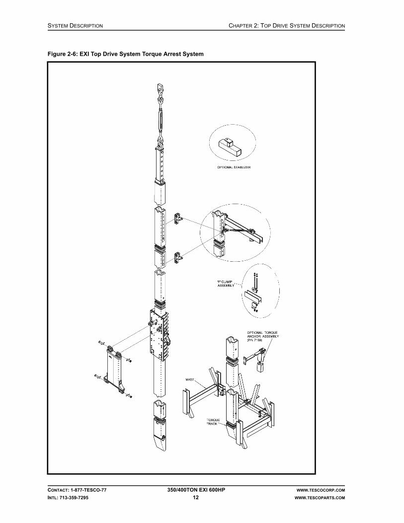
TORQUE ARREST SYSTEM
The torque arrest system consists of the following components:
• torque bushing• extend frame• extend arms• extend hydraulic cylinders• torque track• T-bar• torque beam, torque beam clamps, stabilization devices, and all required rig-up items
Torque Bushing
The torque bushing is attached to the extend frame. It transfers reactive torque from the top drive to the torque track. Ultra High Molecular Weight (UHMW) Polyethylene inserts reduce friction as the top drive moves along the torque track. No lubrication is required.
Extend Frame and Extend Arms
The extend frame is pinned to the top drive. It allows the top drive to extend away from the torque track, enabling improved pipe handling.
Torque Track
The torque track, in conjunction with the torque beam and T-bar, transfers reactive torque to the lower section of the mast and the substructure. The track is suspended from the crown by a cable hanging assembly, and is mounted with a simple clamp anchoring arrangement. Track components can be configured to fit most mast heights.
Torque Beam and T-bar
The torque beam is mounted to the mast, typically to the lowest strongback. It is then connected to the torque track via a T-bar. An offset torque anchor beam and post is available for use on service rigs. This torque anchoring system compensates for the 3.5° lean of the service rig mast.
CONTACT: 1-877-TESCO-77 350/400TON EXI 600HP WWW.TESCOCORP.COM
INTL: 713-359-7295 11 WWW.TESCOPARTS.COM
SYSTEM DESCRIPTION CHAPTER 2: TOP DRIVE SYSTEM DESCRIPTION
Figure 2-6: EXI Top Drive System Torque Arrest System
CONTACT: 1-877-TESCO-77 350/400TON EXI 600HP WWW.TESCOCORP.COM
INTL: 713-359-7295 12 WWW.TESCOPARTS.COM

CHAPTER 2: TOP DRIVE SYSTEM DESCRIPTION SYSTEM DESCRIPTION
SERVICE LOOP
Figure 2-7: Hose Reel/Service Loop
1. Motor power cables2. Ground cable3. Sensor cable4. Robotic cable5. Blower motor power cable6. Auxiliary hydraulic hoses7. Hose reel
CONTACT: 1-877-TESCO-77 350/400TON EXI 600HP WWW.TESCOCORP.COM
INTL: 713-359-7295 13 WWW.TESCOPARTS.COM

SYSTEM DESCRIPTION CHAPTER 2: TOP DRIVE SYSTEM DESCRIPTION
The following cables and hoses are spooled onto the reel prior to shipping.
Electrical Cables
Electrical cables include the following:
• Three 313 Kcm cables.These connect the Varied Frequency Drive to the electric motor.
• One single-conductor 4/0 cable (ground).• One 12 twisted pair motor sensor feedback cable to connect the Top Drive with the Drive
Module.• One #14, 7C Cable for blower motor and heater of top drive motor.• One 4 twisted pair conductor cable to connect the Driller's Control Panel to the Drive
Module.Note: This cable is not part of the service loop.
• One 37C robotics cable connecting the Top Drive to the Drive Module.
Hydraulic Hoses
• Two 3/4 in. R2, 2,000 psi (13.8 MPa) hydraulic hoses; these hoses supply and return hydraulic oil from the mechanical module to the top drive.
DRILLER’S PANEL
The driller’s panel is a stainless steel enclosure that is mounted on the drill floor during installation procedures. It contains all controls, indicators, mounts, gauges and connectors required to operate the top drive. There is an optional air-purge system available for the driller’s panel. All controls are electrically activated hydraulic (24 VDC) non-earth ground.
CONTACT: 1-877-TESCO-77 350/400TON EXI 600HP WWW.TESCOCORP.COM
INTL: 713-359-7295 14 WWW.TESCOPARTS.COM

CHAPTER 2: TOP DRIVE SYSTEM DESCRIPTION SYSTEM DESCRIPTION
SAFETY INTERLOCKS
Emergency Shut Down (E.S.D.)
There are two E.S.D. circuits, each with its own specific function.
E.S.D. on the Driller's Panel
The red E.S.D. mushroom button on the driller's panel trips the main circuit breaker (the breaker supplies 600 VAC to the drive and is located in the power module building). This removes all high voltage power from the drive. The quill stops rotating. This E.S.D. also deactivates the auxiliary hydraulic pump. All devices that operate or rotate at the drill floor become inactive.
E.S.D. on the Main Panel Control System
The red E.S.D. mushroom button on the door of the power module main panel cuts all power to the TESCO power module. This E.S.D. button is interlocked to trip the breaker for the main service power supply.
Air interlocks
Drawworks Interlock and Override
The drum clutch interlock stops the air supply to the drum clutch so that the driller cannot hoist the top drive while the grabber is closed. A push button on the brake handle is used to override this lockout feature during slide drilling operations, etc.
Mud Pump Interlock
The mud pump air interlock is designed to disallow operation of the mud pump unless the mudsaver valve is open.
CONTACT: 1-877-TESCO-77 350/400TON EXI 600HP WWW.TESCOCORP.COM
INTL: 713-359-7295 15 WWW.TESCOPARTS.COM

SYSTEM DESCRIPTION CHAPTER 2: TOP DRIVE SYSTEM DESCRIPTION
Figure 2-8: Driller’s Panel
CONTACT: 1-877-TESCO-77 350/400TON EXI 600HP WWW.TESCOCORP.COM
INTL: 713-359-7295 16 WWW.TESCOPARTS.COM
CHAPTER 2: TOP DRIVE SYSTEM DESCRIPTION SYSTEM DESCRIPTION
SHIPPING CONTAINERS
The EXI Top Drive System is typically shipped in standard 20 ft sea containers. Each container is 20 ft (length) × 8 ft (width) × 8 ft 6 in. (height) (6.1 m × 2.4 m × 2.6 m).
Container 1
Contents:
• top drive in a travel stand• links• counterbalance system• accessories
Container 2
Contents:
• power module • hydraulic power unit
Container 3
Contents:
• rig up kit• accessories• hose reel skid• spare parts
Note: Some countries require that spare parts be shipped separately from the original equipment. In these cases, spare parts will be crated and shipped in a separate container.
CONTACT: 1-877-TESCO-77 350/400TON EXI 600HP WWW.TESCOCORP.COM
INTL: 713-359-7295 17 WWW.TESCOPARTS.COM

SYSTEM DESCRIPTION CHAPTER 2: TOP DRIVE SYSTEM DESCRIPTION
OPTIONS
The following options are available. For more detailed information, contact a TESCO representative.
Elevators and Elevator Links
Automated elevators rated at 350 tons (318 tonnes), associated inserts for various drill pipe sizes, and accessories are available. A variety of link lengths is also available.
Additional Safety Valve and Actuator
Several sizes and thread types are available.
Subs
A complete selection of commonly used saver, casing, cross-over and drill collar handling subs is available. Non-standard subs can be manufactured if requested; delivery can be determined at time of order.
Grabber Drill Pipe Guides
These are used to guide the drill string into the grabber box. The drill pipe guide must match the box of the drill pipe in use. There is a range of sizes available.
Rotary Table Stabilizer Bushings
These urethane bushings fit the standard rotary table profile and protect the table and blowout preventer (BOP) from excessive wear. There is a range of sizes available.
Rotary Hose and Standpipe Extension
All equipment and accessories for these modifications are available.
Torque Arrest System
Optional equipment for non-standard and large mast torque arrest systems is available.
Alarms
The following optional alarm are available:
• extend alert features
CONTACT: 1-877-TESCO-77 350/400TON EXI 600HP WWW.TESCOCORP.COM
INTL: 713-359-7295 18 WWW.TESCOPARTS.COM

CHAPTER 2: TOP DRIVE SYSTEM DESCRIPTION SYSTEM DESCRIPTION
Driller’s Panel
Driller’s panel with hazardous area certification of II 2 G is available.
Power Supply Options
For installations where rig power reserves are not sufficient or where the power quality is low (surges, sudden shutdowns, etc.) TESCO can supply a stand-alone genset unit, powered by a diesel engine. The genset only supplies power to the top drive system allowing for greater power supply flexibility and reliability.
The genset comes is packaged in a modified 20-ft (6 m) sea container equipped with:
• doors and louvres, • optional space heater, • electric panels with plug boards, switches and breakers, • interconnection package.
Other Available Options
• air purge system for the driller's panel and top drive junction box.• workshop/parts containers with workbench and storage cupboards, complete with
interior lighting, optional stepdown transformer, power outlets and space heater.• video monitoring system, with cameras mounted in the derick at the monkey board
and crown levels.
A complete list of all available options and accessories is available from a local TESCO representative.
Table 2-7: Optional stand-alone genset
Imperial Metric
Rated power 1,020HP @ 1,800 rpm, 600VAC, 1,000A, 60Hz
Dimensions 20 ft (L) x 8 ft. (W) x 8 ft 6 in.(H)
6.1 x 2.4 x 2.6 m
Day tank capacity 80 gal 302.5 L
Rig Power 415VAC/3Ø or 220VAC/1Ø
CONTACT: 1-877-TESCO-77 350/400TON EXI 600HP WWW.TESCOCORP.COM
INTL: 713-359-7295 19 WWW.TESCOPARTS.COM

SYSTEM DESCRIPTION CHAPTER 2: TOP DRIVE SYSTEM DESCRIPTION
This page has been left blank intentionally.
CONTACT: 1-877-TESCO-77 350/400TON EXI 600HP WWW.TESCOCORP.COM
INTL: 713-359-7295 20 WWW.TESCOPARTS.COM

SYSTEM DESCRIPTION
ENGINEERING SIGN-OFF
This sign-off sheet indicates that this document has been approved for release by the Engineering Department at TESCO.
Document Complete By Signature Date Signed
Document Reviewed/Approved Date Signed
CONTACT: 1-877-TESCO-77 350/400 TON EXI 600HP WWW.TESCOCORP.COM
INTL: 713-359-7295 21 WWW.TESCOPARTS.COM
chane
Typewritten Text
Edward ChanSept. 28, 2009
chane
Typewritten Text
madejskm
Typewritten Text
Oct 22, 2009

SYSTEM DESCRIPTION
This page has been left blank intentionally.
CONTACT: 1-877-TESCO-77 350/400 TON EXI 600HP WWW.TESCOCORP.COM
INTL: 713-359-7295 22 WWW.TESCOPARTS.COM

DOCUMENT NAME: 880077 REV 2
Installation Guide
EXI Top Drive System
350/400 TON EXI 600HP


COPYRIGHT AND DISCLAIMER INSTALLATION GUIDE
CONTACT: 1-877-TESCO-77 350/400 TON EXI 600HP WWW.TESCOCORP.COM
INTL: 713-359-7295 I WWW.TESCOPARTS.COM
Tesco Corporation ("TESCO") has made every effort to ensure that this document contains accurate and current information for the TESCO top drive, however, the document is intended to be used in conjunction with a complete training program and on-site supervision and TESCO does not warrant or guarantee that the information contained herein is either complete or accurate in every respect, and the reader hereby protects, indemnifies and holds harmless Tesco Corporation together with its directors, officers, employees and agents from and against all liability for personal injury, death or property damage to any person arising directly or indirectly from the use by the reader of the information contained in the document.
This equipment was filled at the factory with TESCO ULTREX™ brand fluids and greases. To ensure maximum performance and to avoid cross-contamination, we strongly recommend the continued usage of TESCO ULTREX™ lubricants, unless otherwise specified.
TESCO ULTREX™ is a trademark and TESCO® is a registered trademark of Tesco Corporation.
Tesco Corporation © 2009
Contact Information
Corporate Head Office3993 W. Sam Houston Parkway No., Suite 100
Houston, Texas, 77043USA
www.tescocorp.comwww.tescoparts.com
Telephone: (713) 359-7000Fax: (713) 359-7001
After Market Sales and Service ContactToll Free North America: 1-877-TESCO-77
International: 713-359-7295

REVISION INFORMATION INSTALLATION GUIDE
CONTACT: 1-877-TESCO-77 350/400 TON EXI 600HP WWW.TESCOCORP.COM
INTL: 713-359-7295 II WWW.TESCOPARTS.COM
Revision Information
Version Date Description of Changes
Rev 0 August 2007 Initial Release
Rev 1 October 2008 Upgrade 350 EXI 600 to 350/400 EXI 600
Rev 2 September 2009 Added TESCO ULTREX™ recommendations and updated the footer to contain contact information.

TABLE OF CONTENTS INSTALLATION GUIDE
CONTACT: 1-877-TESCO-77 350/400 TON EXI 600HP WWW.TESCOCORP.COM
INTL: 713-359-7295 III WWW.TESCOPARTS.COM
TABLE OF CONTENTS
LIST OF FIGURES . . . . . . . . . . . . . . . . . . . . . . . . . . . . . . . . . . . . . . . . . . . . . . . . . . . . . V
LIST OF TABLES . . . . . . . . . . . . . . . . . . . . . . . . . . . . . . . . . . . . . . . . . . . . . . . . . . . . . VII
SAFETY INSTRUCTIONS . . . . . . . . . . . . . . . . . . . . . . . . . . . . . . . . . . . . . . . . . . . . . . . . IX
CHAPTER 1: ABOUT THIS DOCUMENT . . . . . . . . . . . . . . . . . . . . . . . . . . . . . . . . . . . . . . 1
CHAPTER 2: PRE-INSTALLATION ACTIVITIES . . . . . . . . . . . . . . . . . . . . . . . . . . . . . . . . . 3
Rig Installation and Measurement . . . . . . . . . . . . . . . . . . . . . . . . . . . . . . . . . . . . . . . . . . . . . . . . . . . . 3
Power/Service Connection Requirements . . . . . . . . . . . . . . . . . . . . . . . . . . . . . . . . . . . . . . . . . . . . . 3
Main Power Requirements (Rig AC Bus) . . . . . . . . . . . . . . . . . . . . . . . . . . . . . . . . . . . . . . . . . . . . . 5
Fuel Considerations . . . . . . . . . . . . . . . . . . . . . . . . . . . . . . . . . . . . . . . . . . . . . . . . . . . . . . . . . . . . . 5
Air Considerations . . . . . . . . . . . . . . . . . . . . . . . . . . . . . . . . . . . . . . . . . . . . . . . . . . . . . . . . . . . . . . 6
Safe Area Considerations. . . . . . . . . . . . . . . . . . . . . . . . . . . . . . . . . . . . . . . . . . . . . . . . . . . . . . . . . . . 6
Equipment Inspection (Pre-installation) . . . . . . . . . . . . . . . . . . . . . . . . . . . . . . . . . . . . . . . . . . . . . . . 6
CHAPTER 3: RIG UP PROCEDURE . . . . . . . . . . . . . . . . . . . . . . . . . . . . . . . . . . . . . . . . . 7
Equipment Placement. . . . . . . . . . . . . . . . . . . . . . . . . . . . . . . . . . . . . . . . . . . . . . . . . . . . . . . . . . . . . . 7
Optimal Placement of the Power Module and Auxiliary Hydraulic Power Unit . . . . . . . . . . . . . . . . . 7
How to Place the Power Module . . . . . . . . . . . . . . . . . . . . . . . . . . . . . . . . . . . . . . . . . . . . . . . . . . . 8
Optimal Placement of the Service Loop Reel. . . . . . . . . . . . . . . . . . . . . . . . . . . . . . . . . . . . . . . . . . 9
Optimal Placement of the Cable/Hose Saddle . . . . . . . . . . . . . . . . . . . . . . . . . . . . . . . . . . . . . . . . . 9
How to Install the Cable/Hose Saddle . . . . . . . . . . . . . . . . . . . . . . . . . . . . . . . . . . . . . . . . . . . . . . . 10
How to Install the Service Loop . . . . . . . . . . . . . . . . . . . . . . . . . . . . . . . . . . . . . . . . . . . . . . . . . . . . . 11
How to Install the Service Loop: Option 1 . . . . . . . . . . . . . . . . . . . . . . . . . . . . . . . . . . . . . . . . . . . 11
How to Install the Service Loop: Option 2 . . . . . . . . . . . . . . . . . . . . . . . . . . . . . . . . . . . . . . . . . . . 13
Torque Arrest System. . . . . . . . . . . . . . . . . . . . . . . . . . . . . . . . . . . . . . . . . . . . . . . . . . . . . . . . . . . . . 16
Before Installing the Torque Arrest System . . . . . . . . . . . . . . . . . . . . . . . . . . . . . . . . . . . . . . . . . . 16
Torque Arrest System Components . . . . . . . . . . . . . . . . . . . . . . . . . . . . . . . . . . . . . . . . . . . . . . . . 17
Torque Arrest System Configuration . . . . . . . . . . . . . . . . . . . . . . . . . . . . . . . . . . . . . . . . . . . . . . . 17
How to Determine the Torque Track Configuration (where an application drawing is not supplied) . . . . . . . . . . . . 18
Sample Calculation . . . . . . . . . . . . . . . . . . . . . . . . . . . . . . . . . . . . . . . . . . . . . . . . . . . . . . . . . 19
How to Install the Torque Arrest System . . . . . . . . . . . . . . . . . . . . . . . . . . . . . . . . . . . . . . . . . . . . 19
Top Drive . . . . . . . . . . . . . . . . . . . . . . . . . . . . . . . . . . . . . . . . . . . . . . . . . . . . . . . . . . . . . . . . . . . . . . . 23
How to Install the EXI 600 Top Drive . . . . . . . . . . . . . . . . . . . . . . . . . . . . . . . . . . . . . . . . . . . . . . . 23
Extend Arm Adjustment Procedure . . . . . . . . . . . . . . . . . . . . . . . . . . . . . . . . . . . . . . . . . . . . . . . . 27
Driller’s Panel . . . . . . . . . . . . . . . . . . . . . . . . . . . . . . . . . . . . . . . . . . . . . . . . . . . . . . . . . . . . . . . . . . . 28
How to Install the Driller’s Panel. . . . . . . . . . . . . . . . . . . . . . . . . . . . . . . . . . . . . . . . . . . . . . . . . . . 28
Safety Air Interlocks . . . . . . . . . . . . . . . . . . . . . . . . . . . . . . . . . . . . . . . . . . . . . . . . . . . . . . . . . . . . . . 29
About the Mud Pump Interlock . . . . . . . . . . . . . . . . . . . . . . . . . . . . . . . . . . . . . . . . . . . . . . . . . . . . 30

INSTALLATION GUIDE TABLE OF CONTENTS
CONTACT: 1-877-TESCO-77 350/400 TON EXI 600HP WWW.TESCOCORP.COM
INTL: 713-359-7295 IV WWW.TESCOPARTS.COM
Counter-Balance System. . . . . . . . . . . . . . . . . . . . . . . . . . . . . . . . . . . . . . . . . . . . . . . . . . . . . . . . . . .30
How to Set the Counter-Balance Cushion Height . . . . . . . . . . . . . . . . . . . . . . . . . . . . . . . . . . . . . .31
CHAPTER 4: SYSTEM INSPECTION AND START UP . . . . . . . . . . . . . . . . . . . . . . . . . . . . .33
Inspection-General Notes . . . . . . . . . . . . . . . . . . . . . . . . . . . . . . . . . . . . . . . . . . . . . . . . . . . . . . . . . .33
Warnings. . . . . . . . . . . . . . . . . . . . . . . . . . . . . . . . . . . . . . . . . . . . . . . . . . . . . . . . . . . . . . . . . . . . . . . .34
Electrical . . . . . . . . . . . . . . . . . . . . . . . . . . . . . . . . . . . . . . . . . . . . . . . . . . . . . . . . . . . . . . . . . . . . .34
Supply Power and Grounding . . . . . . . . . . . . . . . . . . . . . . . . . . . . . . . . . . . . . . . . . . . . . . . . . . . .34
Other . . . . . . . . . . . . . . . . . . . . . . . . . . . . . . . . . . . . . . . . . . . . . . . . . . . . . . . . . . . . . . . . . . . . . . . .36
System Start Up . . . . . . . . . . . . . . . . . . . . . . . . . . . . . . . . . . . . . . . . . . . . . . . . . . . . . . . . . . . . . . . . . .36
Table of Circuit Breakers and Main Breakers . . . . . . . . . . . . . . . . . . . . . . . . . . . . . . . . . . . . . . . . .37
Support Systems . . . . . . . . . . . . . . . . . . . . . . . . . . . . . . . . . . . . . . . . . . . . . . . . . . . . . . . . . . . . . . .37
How to Start the Generator (if supplied) . . . . . . . . . . . . . . . . . . . . . . . . . . . . . . . . . . . . . . . . . . . . . .37
Top Drive. . . . . . . . . . . . . . . . . . . . . . . . . . . . . . . . . . . . . . . . . . . . . . . . . . . . . . . . . . . . . . . . . . . . .38
Preliminary Checks and ESD Shutdown Test . . . . . . . . . . . . . . . . . . . . . . . . . . . . . . . . . . . . . . . . . . .38
How to Apply 600 VAC Transformer Power . . . . . . . . . . . . . . . . . . . . . . . . . . . . . . . . . . . . . . . . . . . .38
Power up the Drive System . . . . . . . . . . . . . . . . . . . . . . . . . . . . . . . . . . . . . . . . . . . . . . . . . . . . .39
How to Check Phase Rotation . . . . . . . . . . . . . . . . . . . . . . . . . . . . . . . . . . . . . . . . . . . . . . . . . . .39
How to Check the Hydraulic System . . . . . . . . . . . . . . . . . . . . . . . . . . . . . . . . . . . . . . . . . . . . . . . .40
How to Test the ESD on the Driller’s Panel . . . . . . . . . . . . . . . . . . . . . . . . . . . . . . . . . . . . . . . . . . . .41
Final Start Up . . . . . . . . . . . . . . . . . . . . . . . . . . . . . . . . . . . . . . . . . . . . . . . . . . . . . . . . . . . . .41
How to Reset the ACS800 Drive . . . . . . . . . . . . . . . . . . . . . . . . . . . . . . . . . . . . . . . . . . . . . . . . . . .41
Drive Parameters . . . . . . . . . . . . . . . . . . . . . . . . . . . . . . . . . . . . . . . . . . . . . . . . . . . . . . . . . . . . . .42
About Drive Parameters . . . . . . . . . . . . . . . . . . . . . . . . . . . . . . . . . . . . . . . . . . . . . . . . . . . . . . .42
How to Modify Drive Parameters . . . . . . . . . . . . . . . . . . . . . . . . . . . . . . . . . . . . . . . . . . . . . . . . . .42
CHAPTER 5: RIG OUT PROCEDURE. . . . . . . . . . . . . . . . . . . . . . . . . . . . . . . . . . . . . . . .45
Remove the Top Drive . . . . . . . . . . . . . . . . . . . . . . . . . . . . . . . . . . . . . . . . . . . . . . . . . . . . . . . . . . . . .45
Remove the Torque Arrest System . . . . . . . . . . . . . . . . . . . . . . . . . . . . . . . . . . . . . . . . . . . . . . . . . .46
Remove the Service Loop . . . . . . . . . . . . . . . . . . . . . . . . . . . . . . . . . . . . . . . . . . . . . . . . . . . . . . . . . .47
Disconnect the Power and Auxiliary Hydraulic Power Unit . . . . . . . . . . . . . . . . . . . . . . . . . . . . . . .50
APPENDIX A: PRE-INSTALLATION CHECKLIST . . . . . . . . . . . . . . . . . . . . . . . . . . . . . . . .51
APPENDIX B: VISUAL INSPECTION CHECKLISTS . . . . . . . . . . . . . . . . . . . . . . . . . . . . . . .53
APPENDIX C: SLING LOAD RATINGS . . . . . . . . . . . . . . . . . . . . . . . . . . . . . . . . . . . . . . .57
APPENDIX D: HAND SIGNALS FOR BOOM EQUIPMENT OPERATION. . . . . . . . . . . . . . . . .59
APPENDIX E: TRIP AND WARNING CODES . . . . . . . . . . . . . . . . . . . . . . . . . . . . . . . . . . .63
APPENDIX F: TORQUE STANDARDS FOR HIGH STRENGTH FASTENERS. . . . . . . . . . . . . .79
Purpose. . . . . . . . . . . . . . . . . . . . . . . . . . . . . . . . . . . . . . . . . . . . . . . . . . . . . . . . . . . . . . . . . . . . . . . . .79
Standards . . . . . . . . . . . . . . . . . . . . . . . . . . . . . . . . . . . . . . . . . . . . . . . . . . . . . . . . . . . . . . . . . . . . . . .79
Tables . . . . . . . . . . . . . . . . . . . . . . . . . . . . . . . . . . . . . . . . . . . . . . . . . . . . . . . . . . . . . . . . . . . . . . . . . .80
INDEX. . . . . . . . . . . . . . . . . . . . . . . . . . . . . . . . . . . . . . . . . . . . . . . . . . . . . . . . . . . . . .83

LIST OF FIGURES INSTALLATION GUIDE
CONTACT: 1-877-TESCO-77 350/400 TON EXI 600HP WWW.TESCOCORP.COM
INTL: 713-359-7295 V WWW.TESCOPARTS.COM
LIST OF FIGURES
Figure 2-1: Power connection with rig AC bus . . . . . . . . . . . . . . . . . . . . . . . . . . . . . . . . . . . . . . . . . . . 4Figure 2-2: Power connection with integrated generator. . . . . . . . . . . . . . . . . . . . . . . . . . . . . . . . . . . . 4Figure 3-1: EXI 600 optimal equipment placement . . . . . . . . . . . . . . . . . . . . . . . . . . . . . . . . . . . . . . . . 8Figure 3-2: EXI 600 hose saddle placement . . . . . . . . . . . . . . . . . . . . . . . . . . . . . . . . . . . . . . . . . . . . 10Figure 3-3: Installing the service loop through the mast structure. . . . . . . . . . . . . . . . . . . . . . . . . . . . 12Figure 3-4: Cable/hose saddle clamping location . . . . . . . . . . . . . . . . . . . . . . . . . . . . . . . . . . . . . . . . 13Figure 3-5: Front and end views of saddle, hose, and service loop . . . . . . . . . . . . . . . . . . . . . . . . . . 14Figure 3-6: EXI 600 cable/hose saddle capture clamp configuration . . . . . . . . . . . . . . . . . . . . . . . . . 14Figure 3-7: Hoisting the hose saddle. . . . . . . . . . . . . . . . . . . . . . . . . . . . . . . . . . . . . . . . . . . . . . . . . . 15Figure 3-8: Positioning the cable/hose saddle . . . . . . . . . . . . . . . . . . . . . . . . . . . . . . . . . . . . . . . . . . 15Figure 3-9: Torque arrest system configuration . . . . . . . . . . . . . . . . . . . . . . . . . . . . . . . . . . . . . . . . . 18Figure 3-10: Torque arrest system - portable installation . . . . . . . . . . . . . . . . . . . . . . . . . . . . . . . . . . 22Figure 3-11: Link locks in locked and unlocked position . . . . . . . . . . . . . . . . . . . . . . . . . . . . . . . . . . . 24Figure 3-12: EXI Top Drive capture clamp . . . . . . . . . . . . . . . . . . . . . . . . . . . . . . . . . . . . . . . . . . . . . 25Figure 3-13: Securing the auxiliary hydraulic hoses (350 EXI 600) . . . . . . . . . . . . . . . . . . . . . . . . . . 26Figure 3-14: Securing the auxiliary hydraulic hoses (400 EXI 600) . . . . . . . . . . . . . . . . . . . . . . . . . . 26Figure 3-15: Drawworks override installation . . . . . . . . . . . . . . . . . . . . . . . . . . . . . . . . . . . . . . . . . . . 29Figure 3-16: Counter-balance system interface . . . . . . . . . . . . . . . . . . . . . . . . . . . . . . . . . . . . . . . . . 30Figure 3-17: 350 EXI 600 counter-balance cushion height . . . . . . . . . . . . . . . . . . . . . . . . . . . . . . . . . 32Figure 3-18: 400 EXI 600 counter-balance cushion weight. . . . . . . . . . . . . . . . . . . . . . . . . . . . . . . . . 32Figure 4-1: Recommended supply power and grounding . . . . . . . . . . . . . . . . . . . . . . . . . . . . . . . . . . 35Figure 4-2: Change phase rotation . . . . . . . . . . . . . . . . . . . . . . . . . . . . . . . . . . . . . . . . . . . . . . . . . . . 40Figure 5-1: Setting the swivel link locks . . . . . . . . . . . . . . . . . . . . . . . . . . . . . . . . . . . . . . . . . . . . . . . 45Figure 5-2: Spooling the service loop 1. . . . . . . . . . . . . . . . . . . . . . . . . . . . . . . . . . . . . . . . . . . . . . . . 49

INSTALLATION GUIDE LIST OF FIGURES
CONTACT: 1-877-TESCO-77 350/400 TON EXI 600HP WWW.TESCOCORP.COM
INTL: 713-359-7295 VI WWW.TESCOPARTS.COM
This page has been left blank intentionally.

LIST OF TABLES INSTALLATION GUIDE
CONTACT: 1-877-TESCO-77 350/400 TON EXI 600HP WWW.TESCOCORP.COM
INTL: 713-359-7295 VII WWW.TESCOPARTS.COM
LIST OF TABLES
Table 1-1: Where to find more information . . . . . . . . . . . . . . . . . . . . . . . . . . . . . . . . . . . . . . . . . . .1
Table 4-1: Setting drive functions . . . . . . . . . . . . . . . . . . . . . . . . . . . . . . . . . . . . . . . . . . . . . . . . .43
Table B-1: Top drive inspection list . . . . . . . . . . . . . . . . . . . . . . . . . . . . . . . . . . . . . . . . . . . .53Table B-2: Power module inspection list . . . . . . . . . . . . . . . . . . . . . . . . . . . . . . . . . . . . . . . .54Table B-3: Auxiliary hydraulic power unit inspection list . . . . . . . . . . . . . . . . . . . . . . . . . . . .54Table B-4: Cable reel/service loop inspection list . . . . . . . . . . . . . . . . . . . . . . . . . . . . . . . . .55Table B-5: Driller’s panel. . . . . . . . . . . . . . . . . . . . . . . . . . . . . . . . . . . . . . . . . . . . . . . . . . . .55Table C-1: Maximum safe working loads (pounds). . . . . . . . . . . . . . . . . . . . . . . . . . . . . . . .57Table C-2: Rope diameter efficiencies . . . . . . . . . . . . . . . . . . . . . . . . . . . . . . . . . . . . . . . . .58Table D-1: Hand signals for boom operation . . . . . . . . . . . . . . . . . . . . . . . . . . . . . . . . . . . .59Table F-1: Standard torques . . . . . . . . . . . . . . . . . . . . . . . . . . . . . . . . . . . . . . . . . . . . . . . . .80Table F-2: Special fastener torques . . . . . . . . . . . . . . . . . . . . . . . . . . . . . . . . . . . . . . . . . . .81Table F-3: B7 Stud torques . . . . . . . . . . . . . . . . . . . . . . . . . . . . . . . . . . . . . . . . . . . . . . . . . .81Table F-4: Thread engagements. . . . . . . . . . . . . . . . . . . . . . . . . . . . . . . . . . . . . . . . . . . . . .81

INSTALLATION GUIDE LIST OF TABLES
CONTACT: 1-877-TESCO-77 350/400 TON EXI 600HP WWW.TESCOCORP.COM
INTL: 713-359-7295 VIII WWW.TESCOPARTS.COM
This page has been left blank intentionally.

SAFETY INSTRUCTIONS INSTALLATION GUIDE
CONTACT: 1-877-TESCO-77 350/400 TON EXI 600HP WWW.TESCOCORP.COM
INTL: 713-359-7295 IX WWW.TESCOPARTS.COM
SAFETY INSTRUCTIONS
Warning! Before operating and servicing this top drive system, always read and follow all safety instructions such as the warnings and cautions mentioned below and throughout the manual.
Top Drive System users risk injury to themselves and to others if the top drive is used improperly and/or safety precautions are not followed. TESCO advises personnel who work with or near the equipment to always wear proper personal protective equipment (PPE). Proper PPE consists of, but is not limited to, the following:
• hearing protection (ear defenders)• hard hat• safety glasses• steel toe shoes• fall protection when working above 6.5 ft (2 m), or the minimum height
requirement as directed by local jurisdiction.
Caution: This equipment is designed and certified for use in a hazardous environment. When maintenance requires replacement of parts, only identical parts can be used. Using alternate, non-iden-tical parts as a substitution may void compliance and certification.
Caution: Always perform the correct lock-out procedures as recommended by the Safety or Loss Prevention department before implementing maintenance.
Caution: Only authorized personnel can operate the top drive system.
Caution: This equipment can generate noise up to 90 decibels. Hearing protection suitable for this noise level must be worn when operating this equipment.
!
!
!
!
!

INSTALLATION GUIDE SAFETY INSTRUCTIONS
CONTACT: 1-877-TESCO-77 350/400 TON EXI 600HP WWW.TESCOCORP.COM
INTL: 713-359-7295 X WWW.TESCOPARTS.COM
Warning! Electrical voltages of different potentials are used throughout the TESCO top drive components (600 VAC, 208 VAC, 120 VAC, 840 VDC, 5-24 VDC). It is imperative that only qualified personnel install, maintain and/or troubleshoot the electrical systems. A severe hazard exists to personnel not accustomed to, or familiar with, electrical hazards and procedures.
Warning! There are high voltage capacitors installed in the ACS800 drive module. It is imperative that at least 5 minutes elapse, after power to the drive has been turned off, before any testing or repairs be undertaken at the module. The capacitors require time to ‘drain’ their stored electrical energy.
Warning! Accumulators used in the auxiliary hydraulic system are under the pressure of gas. Release this pressure before any maintenance is done on the auxiliary hydraulic system.
!
!
!

CHAPTER 1: ABOUT THIS DOCUMENT INSTALLATION GUIDE
CONTACT: 1-877-TESCO-77 350/400 TON EXI 600HP WWW.TESCOCORP.COM
INTL: 713-359-7295 1 WWW.TESCOPARTS.COM
CHAPTER 1: ABOUT THIS DOCUMENT
This document contains information on how to install the 350/400 TON EXI 600HP top drive, power module, auxiliary hydraulic power unit, torque arrest system, and service loop.
The installation sequence described in this document can be altered to accommodate current rig activity. The procedures described in this document provide instructions on how to do the following:
• perform a pre-installation assessment and equipment check• place equipment• install the service loop and connect services• install the torque arrest system• install the counter-balance system• install the top drive• connect the driller’s panel and safety interlocks• perform a system inspection and commission the unit• rig out
Table 1-1: Where to find more information
For information on Refer to
system components System Description
• setting torque and speed• driller's panel functions and operating descriptions• making connections• drilling ahead• tripping• freeing stuck pipe
Operations Guide
• load path inspections• maintenance/service schedules• component disassembly and reassembly
Maintenance Guide
TESCO manufactured parts and part numbers Parts List
• electrical schematics• hydraulic schematics• cooling schematics• gearbox lubrication schematics
System schematics
available options and spares TESCO representative

INSTALLATION GUIDE CHAPTER 1: ABOUT THIS DOCUMENT
CONTACT: 1-877-TESCO-77 350/400 TON EXI 600HP WWW.TESCOCORP.COM
INTL: 713-359-7295 2 WWW.TESCOPARTS.COM
This page has been left blank intentionally.

CHAPTER 2: PRE-INSTALLATION ACTIVITIES INSTALLATION GUIDE
CONTACT: 1-877-TESCO-77 350/400 TON EXI 600HP WWW.TESCOCORP.COM
INTL: 713-359-7295 3 WWW.TESCOPARTS.COM
CHAPTER 2: PRE-INSTALLATION ACTIVITIES
RIG INSTALLATION AND MEASUREMENT
To ensure that top drive installation progresses smoothly, complete a detailed rig measurement package before ordering equipment. Rig measurement packages are available from TESCO.
Accurate rig measurement helps do the following:
• Determine an equipment placement plan• Determine the best method for installing the top drive• Identify specialized equipment requirements, including the following:
• torque track hanging pad eye• cross-over or saver subs (top drive to drill string)• cable lengths and specific accessories• air/electric safety interlocks• torque arrest system components• cable/hose saddle mounting requirements• mud hose connection• standpipe extension
Ask a qualified TESCO representative to help complete the rig measurement package. This will ensure that the equipment will fit properly within the rig’s configuration.
POWER/SERVICE CONNECTION REQUIREMENTS
Discuss the following items with a qualified TESCO representative before requesting shipment of the top drive system:
• size and output of all generators• type and model of the distribution/SCR systems
The top drive system requires a 600 VAC, 1000A, 60Hz power supply. Where the power supply is 50Hz, an optional package can be installed during the manufacturing process, upon customer request. If the top drive unit is supplied with a generator, then the connection requirements for fuel and air should be considered.
The following figures illustrate the connection considerations to address before the top drive system arrives on location.

INSTALLATION GUIDE CHAPTER 2: PRE-INSTALLATION ACTIVITIES
CONTACT: 1-877-TESCO-77 350/400 TON EXI 600HP WWW.TESCOCORP.COM
INTL: 713-359-7295 4 WWW.TESCOPARTS.COM
Figure 2-1: Power connection with rig AC bus
Figure 2-2: Power connection with integrated generator

CHAPTER 2: PRE-INSTALLATION ACTIVITIES INSTALLATION GUIDE
CONTACT: 1-877-TESCO-77 350/400 TON EXI 600HP WWW.TESCOCORP.COM
INTL: 713-359-7295 5 WWW.TESCOPARTS.COM
Main Power Requirements (Rig AC Bus)
1. Determine a location for the power and mechanical modules.Note: If the rig configuration has not been finalized, then select two possible locations for the power module.
2. Determine where the main disconnect breaker panel will be located.Note: The best location provides room for service personnel and some shelter from the weather.
3. Determine the distance from the AC-Bus to the breaker panel.
4. Determine the distance from the breaker to the power module.
5. Determine if any special equipment is required. Examples: penetration or plug boards.
Note: This equipment is required if the three-phase power cables must pass through walls on their way from the main breaker to the power module.
6. Determine if cable tray or suitable space is available to accommodate three-phase power cables (from the breaker to the power module).
Note: If adequate space is not available, determine what materials would be required to protect the cables from the breaker to the power module.
7. If the customer is providing the main power supply (interconnection package), consult TESCO.
Fuel Considerations
If the top drive unit is supplied with a generator, then the connection requirements for fuel should be considered.
1. Determine the location and type of the fuel supply.Note: The fuel connector line should be 1 in. minimum, and it should be able to supply enough fuel for the power unit’s maximum consumption. The fuel return line should also be 1 in. minimum.
• For the Detroit Diesel 635 hp Genset, maximum consumption is 22.8 gallons per hour (86 liters per hour).
2. Determine the required length of the fuel line. Determine the route it will take from the fuel supply to the power unit.
Note: Avoid routing the fuel line where it might become damaged or pinched.
3. Verify the quality of the fuel supply.Note: Poor fuel quality might require special treatment. For example, fuel line heaters might be required in areas where diesel fuel contains high levels of paraffin.

INSTALLATION GUIDE CHAPTER 2: PRE-INSTALLATION ACTIVITIES
CONTACT: 1-877-TESCO-77 350/400 TON EXI 600HP WWW.TESCOCORP.COM
INTL: 713-359-7295 6 WWW.TESCOPARTS.COM
Air Considerations
If the top drive unit is supplied with a generator, then the connection requirements for air should be considered.
1. Determine if the air supply is adequate.Note: 100 psi (0.69 MPa) minimum with a 1 in. supply line
2. Verify the quality of the air supply.Note: If in an area with high humidity, then a moisture trap might be required to remove moisture from the starter’s air supply.
3. Determine the required length and route of the air supply line.Note: Avoid routing the line where it might become damaged or pinched. If placing the air receiver close to the power unit, this might help it start more easily.
SAFE AREA CONSIDERATIONS
The EXI 600 Top Drive System is provided with guards and suitable protection devices that comply with the Machinery Directive. Safety distances specified in EN294 must be maintained and a minimum IP20 ingress protection as specified in EN60529 must be ensured.
EQUIPMENT INSPECTION (PRE-INSTALLATION)
TESCO inspects all top drive equipment before shipping, however, some damage might occur while equipment is in transit.
It is important to identify any shipping damage as quickly as possible so that necessary repairs, ordering equipment replacements, and optimizing system readiness can be made..
As part of a pre-installation equipment inspection, do the following:
• Check all shipping containers for damage. External damage may indicate damage to contents.
• Visually inspect all principle components for damage or missing parts.• If the top drive system is shipped with fluid levels at full, check the fluid levels. Low
fluid levels may indicate a leak in the hydraulic, cooling, or lubrication system.
A sample equipment checklist is included in “Appendix A: Pre-Installation Checklist”.

CHAPTER 3: RIG UP PROCEDURE INSTALLATION GUIDE
CONTACT: 1-877-TESCO-77 350/400 TON EXI 600HP WWW.TESCOCORP.COM
INTL: 713-359-7295 7 WWW.TESCOPARTS.COM
CHAPTER 3: RIG UP PROCEDURE
EQUIPMENT PLACEMENT
Optimal Placement of the Power Module and Auxiliary Hydraulic Power Unit
Placement of the power module and hydraulic power unit is similar regardless of whether the power is supplied by the rig or by an independent generator. The following diagram shows the optimal placement of the power module and auxiliary hydraulic power unit. This placement is considered ideal for the following reasons:
• The distance from the main disconnect breaker to the power module is short.• The placement allows straight-line access from the cable reel to the cable/hose saddle.• The power module is in the aft position (closest to the generators).• The service loop cable connections are outboard of the rig.
Note: Excess service loop cable can be easily secured on the roof of the power module when it is in this position.
• There is easy access to the power module waterfall.• The auxiliary hydraulic power unit is placed close to the power unit and the connections
of the auxiliary hydraulic hose are easily accessible.• Easy access is provided around the power module and auxiliary hydraulic power unit for
operational and service activities.

INSTALLATION GUIDE CHAPTER 3: RIG UP PROCEDURE
CONTACT: 1-877-TESCO-77 350/400 TON EXI 600HP WWW.TESCOCORP.COM
INTL: 713-359-7295 8 WWW.TESCOPARTS.COM
Although the location of the power module depends on the rig configuration, the factors listed above should be considered when placing equipment.
How to Place the Power Module
1. Ensure the ground surface is level; remove any major obstructions.
2. Install rig matting or another secure material under the equipment location. Note: Ensure the rig matting extends far enough beyond the equipment to provide a walkway for outside service activity.
3. Using a crane or loader, place the power module on the rig matting.
4. Move the auxiliary hydraulic power unit to a location within 30 ft (9.1 m) of the power module.
5. Connect the following cords from the auxiliary hydraulic power unit to the incoming cable panel on the power module:• 1 x Power cable• 1 x Sensor cable
6. Connect the auxiliary hydraulic power module to the hose reel motor.
Figure 3-1: EXI 600 optimal equipment placement

CHAPTER 3: RIG UP PROCEDURE INSTALLATION GUIDE
CONTACT: 1-877-TESCO-77 350/400 TON EXI 600HP WWW.TESCOCORP.COM
INTL: 713-359-7295 9 WWW.TESCOPARTS.COM
Optimal Placement of the Service Loop Reel
The service loop reel acts as a spooling and storage device for electrical cables and auxiliary hydraulic hoses; it is not required during top drive operations.
Note: It is essential to unspool all of the cables from the service loop reel before operating the top drive.
After the hoses and cables are moved onto the saddle and connected to the power unit and top drive, the hose reel can be moved from the installation location to any convenient storage area.
“Figure 3-1: EXI 600 optimal equipment placement” shows the optimal location for the hose reel during installation of the service loop. This position is considered optimal for the following reasons:
• There is a clear view of the cable/hose saddle.• There is straight-line access from the hose reel to the cable/hose saddle.
Although the placement indicated on the illustration is considered optimal, placement of the reel is determined by the available space on site. Always ensure that the selected path is free of sharp edges and corners that can damage the service loop.
Optimal Placement of the Cable/Hose Saddle
The following illustration shows the optimal placement of the cable/hose saddle. This placement is considered ideal because the cable/hose saddle is situated as follows:
• High enough to prevent cables from landing on the rig floor when top drive is lowered:• If the mast is 100 to 125 ft (30.5 to 38.1 m), it is 55 to 65 ft (16.8 to 19.8 m) above the
rig floor.• If the mast height is 130 to 145 ft (39.6 to 44.2 m), it is 75 to 85 ft(22.9 to 25.9 m)
above the rig floor.• Low enough to allow the top drive to reach the rig floor without straining or damaging
cables.• Where there is straight-line cable access from the power unit.
Note: This position is a low activity area for overhead equipment. Accidental dam-age to cables is less likely to occur when the roller saddle is placed here.

INSTALLATION GUIDE CHAPTER 3: RIG UP PROCEDURE
CONTACT: 1-877-TESCO-77 350/400 TON EXI 600HP WWW.TESCOCORP.COM
INTL: 713-359-7295 10 WWW.TESCOPARTS.COM
Although the arrangement shown here is considered optimal, placement of the cable/hose saddle is determined by several factors:
• mast height• strongback location and type• length of traveling equipment (drill string, compensator, blocks, and swivel)• available cable length (maximum service loop length is 225 ft (68.6 m) unless otherwise
requested)• power module location
How to Install the Cable/Hose Saddle
1. Use a crane or other available lifting equipment to move the cable/hose saddle to the rig floor.
2. Use a tugger or cat line to hoist the cable/hose saddle to a predetermined location on the mast.
3. Mount the cable/hose saddle to the strongback.Note: The strongback type determines which mounting hardware should be used. Discuss mounting requirements during the rig measurement and pre-installation analysis.
Figure 3-2: EXI 600 hose saddle placement
For Triple:Service Loop:Approximately 60 to 65 ft (18.2 to 19.8 m) between top drive and hose saddle capture clamp
Hose Saddle:Mounted 55 to 65 ft (17 to 20 m) above drill floor (depending on monkey board height and sling length)
For Double:Service Loop:Approximately 50 to 60 ft (15.2 to 18.3 m) between top drive and hose saddle capture clamp
Hose Saddle:Mounted 45 to 55 ft (14 to 17 m) above drill floor (depending on monkey board height and sling length)
Standpipe Hose
100-125 ft

CHAPTER 3: RIG UP PROCEDURE INSTALLATION GUIDE
CONTACT: 1-877-TESCO-77 350/400 TON EXI 600HP WWW.TESCOCORP.COM
INTL: 713-359-7295 11 WWW.TESCOPARTS.COM
HOW TO INSTALL THE SERVICE LOOP
There are typically two options to installing the service loop:
• Option 1: The service loop needs to be strung through the mast structure. This is typically done in a permanent installation.
• Option 2: The service loop is hung outside the mast structure and does not have to pass through the mast structure. The service loop is clamped to a cable/hose saddle and hoisted up beside the mast.
How to Install the Service Loop: Option 1
Use this procedure to string the service loop through the mast structure.
1. Ensure the auxiliary hydraulic lines are connected to the hose reel control.
2. Use a soft sling to bundle the ends of the cables and hoses of the service loop together.
3. Attach the bundle end to the cable of the floor tugger or loader.
4. Use the hose reel and tugger to lay out the length of the service loop that will travel with the top drive.
5. Measure and mark the length of the service loop that will hang from the hose saddle to the top drive starting at the hose or cable ends. Keep the service loop tidy and ensure the ends of all the hydraulic hoses and cables are as even with each other as possible.
6. Insert the hoses and cables in the cable/hose saddle capture clamp and tighten the clamp. Refer to Figure 3-6 on page 14 for the positions where the cables and hoses must be inserted.
7. Attach a tugger line to the cable/hose saddle, refer to Figure 3-3.
8. String a second tugger line through the mast structure where the service loop should go through the mast structure (point A on Figure 3-3) and attach this tugger line to the service loop about a third of the length between the service loop end and the cable/hose saddle (point B on Figure 3-3).
9. Hoist both the tugger lines at the same time. Hoist the cable/hose saddle as high as possible. At some point the service loop will get hoisted through the mast structure.
Note: Take care so that the service loop does not get snagged in the mast structure.
At this point the free end of the service loop should hang free in the mast.
10. Lower the tugger attached to the free end of the service loop until the service loop hangs from the cable/hose saddle.
INSTALLATION GUIDE CHAPTER 3: RIG UP PROCEDURE
CONTACT: 1-877-TESCO-77 350/400 TON EXI 600HP WWW.TESCOCORP.COM
INTL: 713-359-7295 12 WWW.TESCOPARTS.COM
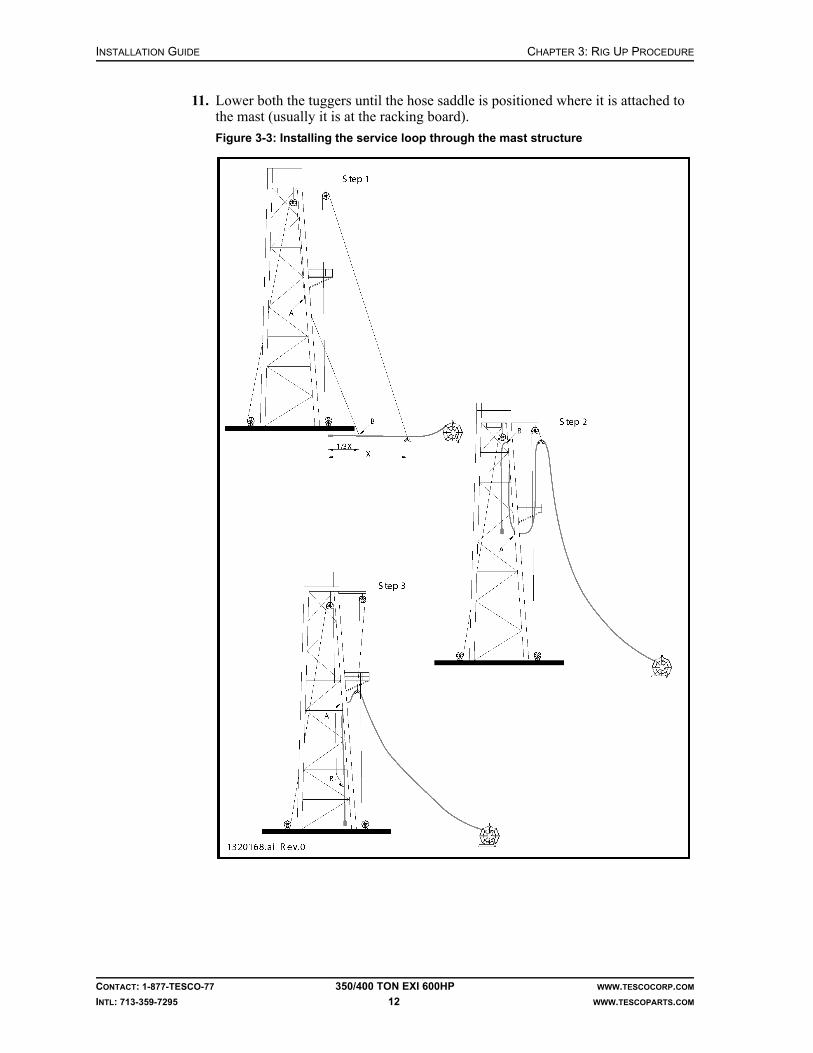
11. Lower both the tuggers until the hose saddle is positioned where it is attached to the mast (usually it is at the racking board).
Figure 3-3: Installing the service loop through the mast structure
CHAPTER 3: RIG UP PROCEDURE INSTALLATION GUIDE
CONTACT: 1-877-TESCO-77 350/400 TON EXI 600HP WWW.TESCOCORP.COM
INTL: 713-359-7295 13 WWW.TESCOPARTS.COM
12. Install the hanging slings for the cable/hose saddle to the pad eyes with a shackle, or wrap it around a suitable beam, refer to Figure 3-8.
13. Use a shackle to attach the cable/hose saddle to the hanging slings.Note: The hanging slings must be strong enough to hold the loads of more than 2,000 lb (907.2 kg).
14. Lower the tugger attached to the cable/hose saddle further until the weight transfers to the hanging sling.
15. Install a back-up safety sling around the hose saddle
Caution: This back up sling is considered critical safety equipment.
16. Disconnect the tuggers from the service loop. The service loop is now ready to connect to the top drive.
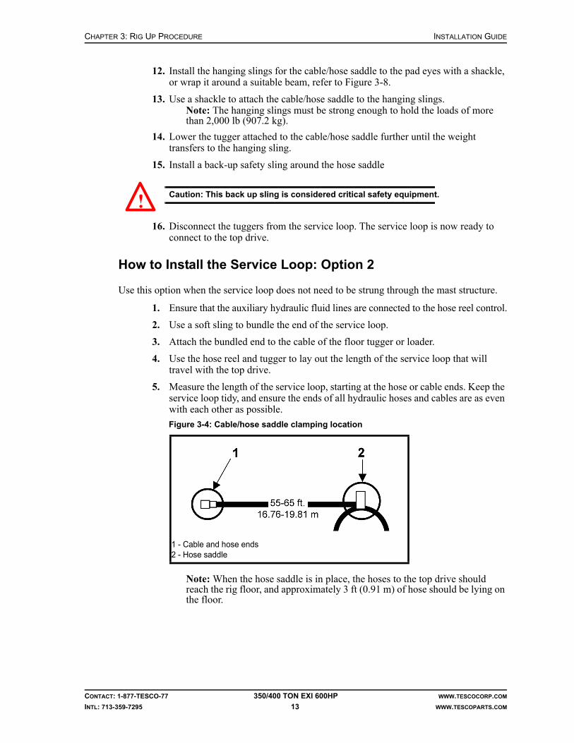
How to Install the Service Loop: Option 2
Use this option when the service loop does not need to be strung through the mast structure.
1. Ensure that the auxiliary hydraulic fluid lines are connected to the hose reel control.
2. Use a soft sling to bundle the end of the service loop.
3. Attach the bundled end to the cable of the floor tugger or loader.
4. Use the hose reel and tugger to lay out the length of the service loop that will travel with the top drive.
5. Measure the length of the service loop, starting at the hose or cable ends. Keep the service loop tidy, and ensure the ends of all hydraulic hoses and cables are as even with each other as possible.
Note: When the hose saddle is in place, the hoses to the top drive should reach the rig floor, and approximately 3 ft (0.91 m) of hose should be lying on the floor.
Figure 3-4: Cable/hose saddle clamping location
1 - Cable and hose ends2 - Hose saddle
!

INSTALLATION GUIDE CHAPTER 3: RIG UP PROCEDURE
CONTACT: 1-877-TESCO-77 350/400 TON EXI 600HP WWW.TESCOCORP.COM
INTL: 713-359-7295 14 WWW.TESCOPARTS.COM
6. When the correct length has been spooled off the reel, insert the hoses and cable in the cable/hose saddle capture clamp.
7. Connect the cable/hose saddle to the cable of the floor tugger or crane.
Figure 3-5: Front and end views of saddle, hose, and service loop
Figure 3-6: EXI 600 cable/hose saddle capture clamp configuration

CHAPTER 3: RIG UP PROCEDURE INSTALLATION GUIDE
CONTACT: 1-877-TESCO-77 350/400 TON EXI 600HP WWW.TESCOCORP.COM
INTL: 713-359-7295 15 WWW.TESCOPARTS.COM
8. Hoist the saddle and hoses into position below the racking platform.Note: Hoist the saddle slightly higher than its final position.
9. Install the hanging sling for the cable/hose saddle at the racking platform.Note: Attach the hanging sling to the pad eye with a shackle, or wrap it around a suitable beam, refer to Figure 3-8.
10. Use a shackle to attach the cable/hose saddle to the hanging sling.Note: The cable/hose saddle sling must be strong enough to hold loads of more than 2,000 lb (907.2 kg).
11. Use the floor tugger or crane to lower the saddle until the weight transfers to the hanging sling.
Figure 3-7: Hoisting the hose saddle
Figure 3-8: Positioning the cable/hose saddle

INSTALLATION GUIDE CHAPTER 3: RIG UP PROCEDURE
CONTACT: 1-877-TESCO-77 350/400 TON EXI 600HP WWW.TESCOCORP.COM
INTL: 713-359-7295 16 WWW.TESCOPARTS.COM
12. Install a back-up safety sling around the hose saddle.
Caution: This back-up sling is considered critical safety equipment.
13. Lower the crane or floor tugger cable.
14. Attach the crane or floor tugger cable to the sling at the free end of the service loop.
15. Hoist the free end of the service loop to the rig floor and secure it in place until it can be connected to the top drive and driller’s panel.
TORQUE ARREST SYSTEM
Before Installing the Torque Arrest System
Install a hanging pad eye in the crown before installing the torque arrest system. This pad eye must be designed and installed to support the hanging weight of the entire torque assembly (safe working load of 15,000 lb (6804 kg) plus the recommended safety factor for overhead equipment).
The pad eye is typically placed 25 in. (63.5 cm) back from the crown cluster center. It is easiest to install the pad eye when the mast is down. Discuss installation procedures with a TESCO representative as part of pre-installation activities.
Warning! Design and installation of the pad eye should meet or exceed all safety specifications for the operating area and operating conditions.
A variety of stabilization devices can be used to hold the torque arrest system in place during operations. It is easiest to install the stabilization systems before raising the mast.
!
!

CHAPTER 3: RIG UP PROCEDURE INSTALLATION GUIDE
CONTACT: 1-877-TESCO-77 350/400 TON EXI 600HP WWW.TESCOCORP.COM
INTL: 713-359-7295 17 WWW.TESCOPARTS.COM
Torque Arrest System Components
A standard torque arrest system includes the torque beam, T-bar, and the following torque track sections (typical). The number of torque track sections depends on the free working height of the mast and is shown on the application drawing supplied with the top drive system:
• one adjustable hanging sling• one cable clamp mount and cable capture clamp• one 18.5 ft (5.6 m) reversible, bolted, bottom torque track section• five 18.5 ft (5.6 m) standard torque track sections• one 10 ft (3.1 m) torque track section• one 5 ft (1.5 m) torque track section
Obtain additional length by lengthening the top section hanging sling. Purchase additional torque track sections to accommodate larger masts.
The following two sections of torque track are also included:
• one 1.3 ft (0.4 m) deflector section (bull nose)• one 2 ft (0.6 m) torque track section
Caution: Never subject these sections to torque. Mount them below the torque beam only.
The deflector section is always mounted at the bottom. Its tapered design assists in mounting the torque bushing onto the torque track.
Torque Arrest System Configuration
The following must be known before determining the torque track configuration:
• height of the hanging pad eye for the torque track, measured from the rig floor (A)• position (height above rig floor) where the torque beam and T-bar will be mounted (B)• length of the hanging assembly for the torque track, including hanging swivel, nut, and
shackles (2.5 ft minimum (0.8 m) to 15 ft (4.6 m) maximum)Note: Shorter configurations are safer and more practical.
Note: Correct calculations will help ensure that the torque bushing will not come off of the torque tube when the blocks are fully hoisted to the crown.
• the location of any upper strongback that may interfere with the vertical hanging of the torque track
Note: If the torque track is to remain in the mast during rig moves, match the torque track connections to the mast connections wherever possible.
!

INSTALLATION GUIDE CHAPTER 3: RIG UP PROCEDURE
CONTACT: 1-877-TESCO-77 350/400 TON EXI 600HP WWW.TESCOCORP.COM
INTL: 713-359-7295 18 WWW.TESCOPARTS.COM
How to Determine the Torque Track Configuration (where an application drawing is not supplied)
Sketch and calculate the following on paper before connecting sections of torque track.
1. Place the bottom of the deflector section 7 to 8 ft (2.1 to 2.4 m) above the drill floor (C).
2. Place the bottom bolted section of torque track above the deflector section.Note: Ensure that a suitable strongback for mounting the torque beam and T-bar is available somewhere along the length of the bolted section of torque track. Remember that the bolted section is reversible.
3. Stack the track sections (18.5 ft, 5 ft and 10 ft sections) until they are 5 to 15 ft (1.5 to 4.6 m) from the pad eye.
4. Determine the length of hanging assembly required.Note: Ensure that the length of hanging assembly is incorporated into the calculation.
5. Calculate the height of the torque bushing to ensure that it will not come off the top end of the torque track when it is in the uppermost position.
Figure 3-9: Torque arrest system configuration

CHAPTER 3: RIG UP PROCEDURE INSTALLATION GUIDE
CONTACT: 1-877-TESCO-77 350/400 TON EXI 600HP WWW.TESCOCORP.COM
INTL: 713-359-7295 19 WWW.TESCOPARTS.COM
Sample Calculation
If the mast height is 102 ft (31.1 m):
1. 102 ft less 7 ft (height above the rig floor for the deflector section) = 95 ft (29.0 m)
2. 95 ft less 2.5 ft (minimum hang sling length) = 92.5 ft (28.2 m)
3. 92.5 ft divided by 18.5 = five full length tubes; this does not include the deflector section.
Torque beam desired height = 11 ft (3.4 m)
The rig up would be as follows:
* The bolted track section would be run with the bolt section down, below the standard track sections and 10 ft (3 m) and 5 ft (1.5 m) sections. The deflector track section would be mounted below the bolted section.
How to Install the Torque Arrest System
Use this procedure to install the torque arrest track system. Refer to Figure 3-10 on page 22.
1. Ensure the hanging pad-eye for the torque track is installed in the crown.Note: Normal placement for a standard track is 25 in. back from the crown cluster center.
2. Assemble the torque beam, T-bar, and T-bar clamp.
Warning! Assemble the above with the T-bar at mid-length. This balances the assembly during lifting.The assembly should not be fully torqued, but it should hold the T-bar securely in place.
3. Use the tugger to move the torque beam onto the drill floor and up to the lowest, most practical strongback beam.
Note: Install the torque beam low in the mast. Attach it to a large beam anywhere between 10 ft (3 m) and 16 ft (4.9 m) above the drill floor. If it is installed any higher, additional stabilization below the torque beam might be required. TESCO can supply additional stabilization, if required.
4. Use four clamps to mount the torque beam to the selected supporting beam.Note: On a permanent installation, the anchor beam clamp can be weld onto the mast.
Track Part Qty Length (ft) Total Length (ft)
Hanging Track 1 18.5 18.5
Standard Tracks 2 37 (18.5 x 2) 55.5
10 ft section 1 10 65.5
5 ft section 1 5 70.5
Bolted* section 1 18.5 89
Deflector 1 1.3 90.3
Hanging Assembly 1 Set to 3 feet 90.3
!
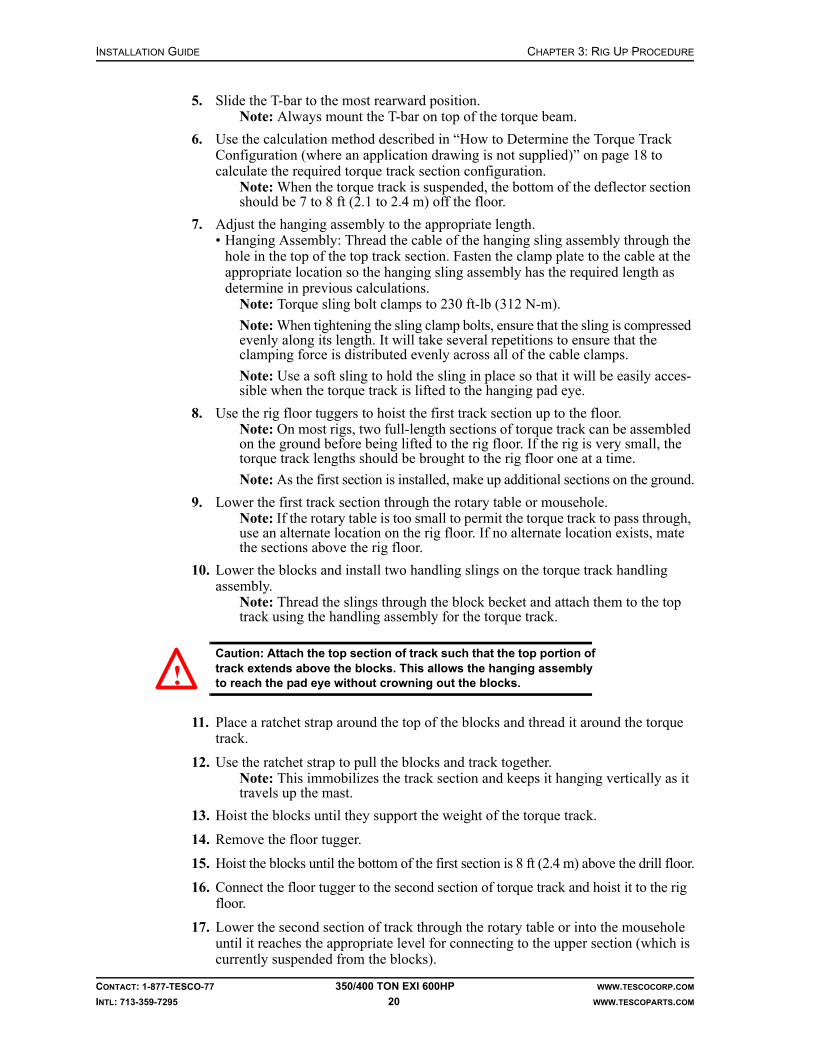
INSTALLATION GUIDE CHAPTER 3: RIG UP PROCEDURE
CONTACT: 1-877-TESCO-77 350/400 TON EXI 600HP WWW.TESCOCORP.COM
INTL: 713-359-7295 20 WWW.TESCOPARTS.COM
5. Slide the T-bar to the most rearward position.Note: Always mount the T-bar on top of the torque beam.
6. Use the calculation method described in “How to Determine the Torque Track Configuration (where an application drawing is not supplied)” on page 18 to calculate the required torque track section configuration.
Note: When the torque track is suspended, the bottom of the deflector section should be 7 to 8 ft (2.1 to 2.4 m) off the floor.
7. Adjust the hanging assembly to the appropriate length.• Hanging Assembly: Thread the cable of the hanging sling assembly through the
hole in the top of the top track section. Fasten the clamp plate to the cable at the appropriate location so the hanging sling assembly has the required length as determine in previous calculations.
Note: Torque sling bolt clamps to 230 ft-lb (312 N-m).
Note: When tightening the sling clamp bolts, ensure that the sling is compressed evenly along its length. It will take several repetitions to ensure that the clamping force is distributed evenly across all of the cable clamps.
Note: Use a soft sling to hold the sling in place so that it will be easily acces-sible when the torque track is lifted to the hanging pad eye.
8. Use the rig floor tuggers to hoist the first track section up to the floor.Note: On most rigs, two full-length sections of torque track can be assembled on the ground before being lifted to the rig floor. If the rig is very small, the torque track lengths should be brought to the rig floor one at a time.
Note: As the first section is installed, make up additional sections on the ground.
9. Lower the first track section through the rotary table or mousehole.Note: If the rotary table is too small to permit the torque track to pass through, use an alternate location on the rig floor. If no alternate location exists, mate the sections above the rig floor.
10. Lower the blocks and install two handling slings on the torque track handling assembly.
Note: Thread the slings through the block becket and attach them to the top track using the handling assembly for the torque track.
Caution: Attach the top section of track such that the top portion of track extends above the blocks. This allows the hanging assembly to reach the pad eye without crowning out the blocks.
11. Place a ratchet strap around the top of the blocks and thread it around the torque track.
12. Use the ratchet strap to pull the blocks and track together.Note: This immobilizes the track section and keeps it hanging vertically as it travels up the mast.
13. Hoist the blocks until they support the weight of the torque track.
14. Remove the floor tugger.
15. Hoist the blocks until the bottom of the first section is 8 ft (2.4 m) above the drill floor.
16. Connect the floor tugger to the second section of torque track and hoist it to the rig floor.
17. Lower the second section of track through the rotary table or into the mousehole until it reaches the appropriate level for connecting to the upper section (which is currently suspended from the blocks).
!

CHAPTER 3: RIG UP PROCEDURE INSTALLATION GUIDE
CONTACT: 1-877-TESCO-77 350/400 TON EXI 600HP WWW.TESCOCORP.COM
INTL: 713-359-7295 21 WWW.TESCOPARTS.COM
18. Install all the studs and lower nuts before connecting the sections. Note: The studs cannot be installed after the track sections are connected.
19. Lower the blocks and upper section of track and connect the two sections. Bolt the sections together, ensuring a flush connection.
Note: Coat all studs with an anti-seize compound before installation.
20. Torque the studs to 350 ft-lb (475 N-m).
21. Repeat steps 16.–20. until all sections are connected and supported by the blocks.Note: The last section that is installed is typically composed of the reversible bolted section, the deflector section and, if required, the two-foot track section.
22. Use a ratchet strap to secure the extend arms of the torque bushing in place.
23. Attach a tugger to the torque bushing and move the bushing onto the drill floor.Note: Ensure that the extend frame is down.
24. Position the torque bushing over hole center.
25. Use the blocks to lower the assembled torque track and stab it through the torque bushing.
26. When the torque bushing is in position, pin it in place.Note: Ensure that the top drive pin ends are at least 8 ft (2.4 m) above the drill floor. If the torque bushing is too tight to move freely along the torque track, adjust the torque bushing by adding additional shim packs. To ensure a proper fit, periodically check the bushing during the first few days of operation.
27. After the torque bushing is installed, raise the blocks to the crown.
28. Connect the hanging assembly of the torque track to the pad eye.
29. When the hanging assembly is connected to the pad eye, lower the blocks until the weight of the track is transferred to the pad eye.
Note: Do not remove the handling assembly yet. Use the blocks to raise and lower the torque track while making the fine adjustments required to connect the T-bar to the bolted section.
30. Connect the T-bar to the bolted section of the torque track.
Caution: When connecting the bolted section of the torque track, ensure that the full weight of the torque track is suspended from the pad eye. If possible, mount it so the T-bar sits approximately 1/8 in. above the T-bar clamp so that the torque hanging assembly carries the total weight of the torque track.
Note: If the T-bar and bolted sections are not vertically aligned, then use the blocks to hoist the track. While the track weight is suspended from the blocks, adjust the hanging swivel as required. Up to 2 in. (5.1cm) of adjustment is available in the hanging assembly and the lock nut.
31. When all T-bar fastening bolts are tight, move the T-bar to the correct position in the T-bar seat and tighten the clamp to hold it in position.
Note: Hang the center of the torque track vertically, 25 in. (63 cm) back from the hole center.
32. Tighten the lock nut on the hanging assembly.
33. Remove the handling assembly at the crown and lower the blocks.
34. Install stabilization systems.Note: These are most easily installed when the mast is down, but can also be installed during rig-up.
35. Attach the stabilization devices to the torque track as shown in the following illustrations.
!
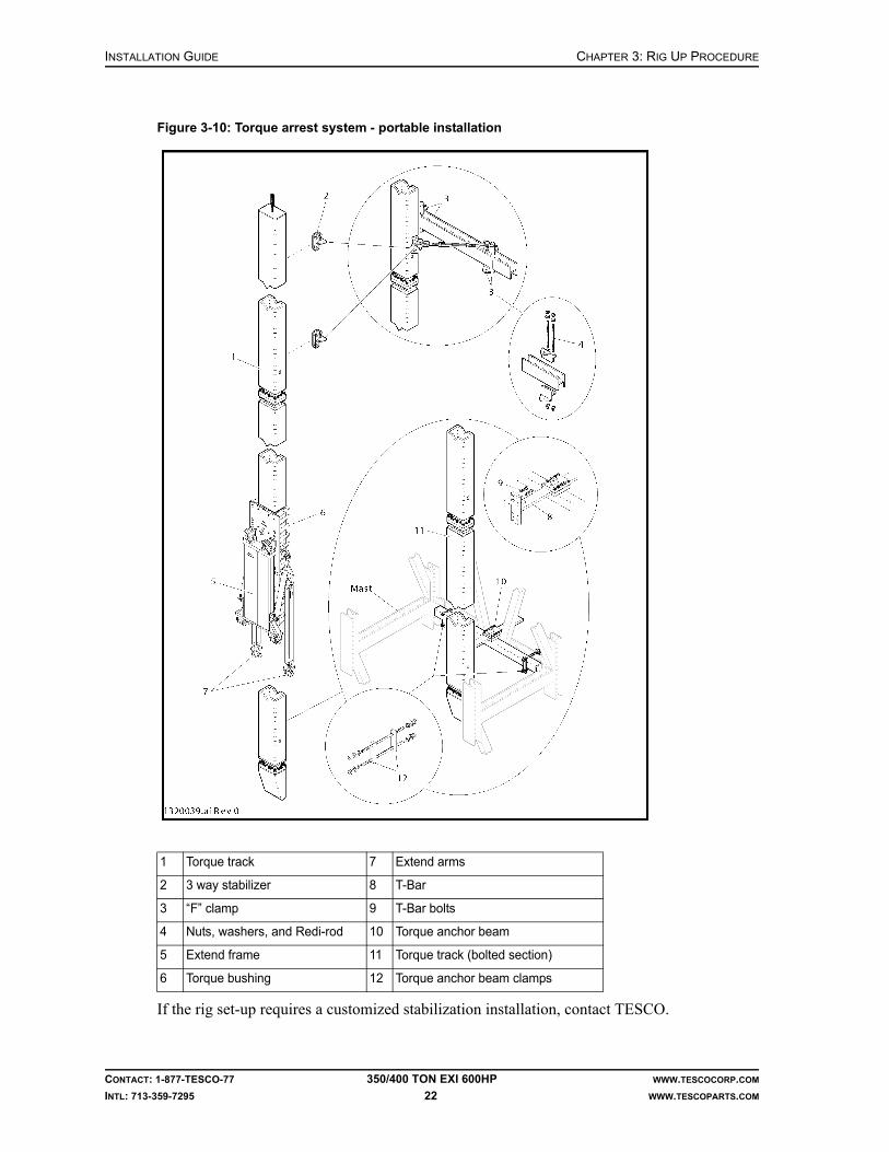
INSTALLATION GUIDE CHAPTER 3: RIG UP PROCEDURE
CONTACT: 1-877-TESCO-77 350/400 TON EXI 600HP WWW.TESCOCORP.COM
INTL: 713-359-7295 22 WWW.TESCOPARTS.COM
If the rig set-up requires a customized stabilization installation, contact TESCO.
Figure 3-10: Torque arrest system - portable installation
1 Torque track 7 Extend arms
2 3 way stabilizer 8 T-Bar
3 “F” clamp 9 T-Bar bolts
4 Nuts, washers, and Redi-rod 10 Torque anchor beam
5 Extend frame 11 Torque track (bolted section)
6 Torque bushing 12 Torque anchor beam clamps

CHAPTER 3: RIG UP PROCEDURE INSTALLATION GUIDE
CONTACT: 1-877-TESCO-77 350/400 TON EXI 600HP WWW.TESCOCORP.COM
INTL: 713-359-7295 23 WWW.TESCOPARTS.COM
TOP DRIVE
How to Install the EXI 600 Top Drive
Before moving the top drive onto the rig floor, ensure that the swivel yoke link with integral counter-balance is installed in the top drive and is securely supported by the top drive handling frame.
1. Using blocks or a crane, move the top drive to the rig floor.Note: If using the block, attach a hold-back line from the handling frame of the top drive to a loader or cat line tugger. Use the line to prevent the top drive from swinging when it is lifted off the rig floor.
Caution: Always attach the hoisting line to the top drive handling frame and not to any part of the top drive when the top drive is installed in the handling frame.
2. Position the top drive over the hole center.
3. Lower the blocks and remove the lifting sling.
4. Lower the blocks further and install the top drive yoke into the block hook or beckett.
5. Raise the blocks to support weight of the top drive.
Caution: Do not lift the top drive off the floor.
6. Remove yoke/link support pins. Rotate supports to allow yoke/link removal.
7. Remove the pins on the handling frame of the top drive (three or four in total, depending on the unit type).
Caution: Ensure the link lock turn buckles are set so that the top drive will not tilt forward. See Figure 3-11.
!
!
!

INSTALLATION GUIDE CHAPTER 3: RIG UP PROCEDURE
CONTACT: 1-877-TESCO-77 350/400 TON EXI 600HP WWW.TESCOCORP.COM
INTL: 713-359-7295 24 WWW.TESCOPARTS.COM
8. Lift the top drive until it is clear of the handling frame.
9. Use the floor tugger to remove the handling frame from the rig floor.
10. Use the blocks to position the top drive so that it can be joined to the extend frame. Align the ears on the top drive with the extend frame and extend arms and pin them in place.
11. Remove the pin that is holding the torque bushing in place on the torque track.Note: The weight of the top drive and torque bushing are now suspended from the blocks.
12. Unscrew the link lock turn buckles to remove the load, then unpin them and remove them to allow the links to swivel freely. Refer to Figure 3-11.
Caution: Ensure the top drive is pinned to the torque bushing before the link lock turn buckles are removed. The top drive will tilt forward if it is not pinned to the torque bushing.
13. Lower the top drive to the rig floor.
14. Check if the top drive hangs vertical. If not, refer to the “Extend Arm Adjustment Procedure” on page 27.
15. Reposition the T-bar so the top drive sits over the hole center, and secure it in place (if required). Refer to “Appendix F: Torque Standards for High Strength Fasteners” for the torque specification of the T-bar clamp bolts.
Figure 3-11: Link locks in locked and unlocked position
!

CHAPTER 3: RIG UP PROCEDURE INSTALLATION GUIDE
CONTACT: 1-877-TESCO-77 350/400 TON EXI 600HP WWW.TESCOCORP.COM
INTL: 713-359-7295 25 WWW.TESCOPARTS.COM
16. Tighten the T-bar connection to secure it in place. Refer to “Appendix F: Torque Standards for High Strength Fasteners”.
17. Locate the service loop. It should have been installed before this point. If the service loop has not been installed, see “How to Install the Service Loop: Option 1” on page 11 or “How to Install the Service Loop: Option 2” on page 13.
18. Clamp the following cables for the service loop to the top drive capture clamp. Allow enough cable to connect them to the top drive junction box.
Note: There should be no strain on the cables between the clamp and the motor junction box.
• one sensor cable• one robotics cable• one blower motor and heater cable• one ground cable• three motor power cables
19. Connect the cables to the receptacles on the top drive junction box or pigtails.
20. Connect the supply and return auxiliary hydraulic hoses to the quick connectors on the top drive.
21. Attach the kellum grips of the hoses to the 10-station manifold bracket, refer to Figure 3-13.
Note: The kellum grips must hold the weight of the hoses.
Figure 3-12: EXI Top Drive capture clamp

INSTALLATION GUIDE CHAPTER 3: RIG UP PROCEDURE
CONTACT: 1-877-TESCO-77 350/400 TON EXI 600HP WWW.TESCOCORP.COM
INTL: 713-359-7295 26 WWW.TESCOPARTS.COM
22. When all service loop hoses and cables are attached, check the loop position.• The loop should be off the floor.• There should not be any snagging/interference.
23. Re-check all hose connections.
24. Ensure that all required valves are open.
Figure 3-13: Securing the auxiliary hydraulic hoses (350 EXI 600)
Figure 3-14: Securing the auxiliary hydraulic hoses (400 EXI 600)

CHAPTER 3: RIG UP PROCEDURE INSTALLATION GUIDE
CONTACT: 1-877-TESCO-77 350/400 TON EXI 600HP WWW.TESCOCORP.COM
INTL: 713-359-7295 27 WWW.TESCOPARTS.COM
25. When the top drive and driller’s panel are connected, continue with additional set-up procedures, or begin rig commissioning.
Note: The counter-balance cushion height can be set after all support systems are running. The cushion height must be set before any drilling operations start. See “How to Set the Counter-Balance Cushion Height” on page 31.
Caution: After installation, ensure that safe access is provided to all areas on and around the top drive where adjustments and maintenance are necessary.
Extend Arm Adjustment Procedure
The aim of this procedure is to ensure that the top drive hangs vertical and is aligned with the hole center. Firstly, adjust the extend arms to ensure the top drive is vertical. Secondly, adjust the torque track to align the top drive with the hole center.
1. Start with the extend frame retracted in and a joint in the rotary table.
2. Move the grabber box up to the point where the bottom end of the saver sub is protruding through the grabber box.
3. Lower the top drive so that it is just above the joint in the rotary table (2 to 6 in).
4. Place a level on the top drive upper grabber leg to determine how the extend arms (extend or retract) will have to be adjusted. The top drive should hang vertically; if adjustment is required, loosen the jam nuts on the extend arm clevises.
5. Remove the lower extend arm pins.
Warning! Use a cat line to support the top drive so it does not tilt forward and to enable easy access and adjustment.
6. Adjust the arms appropriately by screwing the clevis in or out. This is a trial and error process that requires guesswork. Ensure the extend arms are equal length by measuring the distance from the end of the extend arm to the center of the pin hole in the clevis (allowable variance is + 1/16 in).
7. Hand tighten the jam nut and re-pin the extend arms to the extend frame mounts.
8. Visually inspect the level. If satisfactory, as judged by the level, continue to the next step. If the top drive is not satisfactorily level, repeat steps 4. through 8. until the top drive is vertical (this is a trial and error process and may take 3 to 4 adjustments before the top drive is vertical).
9. Torque the jam nuts appropriately (2,300 ft-lb/3,119 N-m dry, 1,725 ft-lb/2,339 N-m lubed) with a wrench and ensure the retaining cap screws are installed on the lower extend arm pins.
10. Visually inspect the alignment of the saver sub with the joint in the rotary table. If they are not aligned, adjust the torque track by adjusting the T-bar in the T-bar clamp.
Note: The torque track stabilizers must be adjusted accordingly to ensure the torque track hangs parallel to hole center.
!
!

INSTALLATION GUIDE CHAPTER 3: RIG UP PROCEDURE
CONTACT: 1-877-TESCO-77 350/400 TON EXI 600HP WWW.TESCOCORP.COM
INTL: 713-359-7295 28 WWW.TESCOPARTS.COM
DRILLER’S PANEL
How to Install the Driller’s Panel
The location selected for the driller’s panel should be as follows:
• within reach of the driller• where there is an unobstructed view of the top drive, rig floor, mast and travelling
equipment• where the driller has an unobstructed view of the robotic functions during operation• in a safe position• where there is sufficient lighting to clearly read all labels
The bottom of the driller’s panel is equipped with a four-bolt mounting plate. Use this to attach the control panel to a custom-built pedestal or existing framework. Some on-site fabrication of a mounting site might be required.
1. Locate the position for the driller’s panel.
2. Fabricate a mounting location if required.
3. Drill bolt holes in the mounting location.Note: A second mounting plate is provided to use as a template.
Caution: To avoid damaging components, avoid mounting the driller's panel in a location that is exposed to vibration.
4. Install the 4-twisted-pair control cable from the driller’s panel to the power module (cord B).
5. Mount the brake handle control box to the brake handle.
6. Connect the brake handle control box to the driller’s panel.Note: The driller’s panel has three labeled extension cords with military connectors. Use the correct cord (cord F).
!

CHAPTER 3: RIG UP PROCEDURE INSTALLATION GUIDE
CONTACT: 1-877-TESCO-77 350/400 TON EXI 600HP WWW.TESCOCORP.COM
INTL: 713-359-7295 29 WWW.TESCOPARTS.COM
SAFETY AIR INTERLOCKS
For detailed information about safety interlocks, refer to the schematics for the unit and/or contact a qualified TESCO representative.
How to Install the Drawworks Interlock and Override
The drum clutch interlock stops the air supply to the drum clutch so that the driller cannot hoist the top drive while the grabber is closed. Use the push button on the brake handle to override this lockout feature. The drawworks interlock override cannot be installed until the driller’s panel is in place.
1. Shut off the air supply from the compressor to the drum clutch control.Note: Use an isolator valve if necessary.
2. Disconnect the hose for the drum clutch air supply from the control valve.
3. Connect the air supply hose to an air/electric solenoid valve.Note: If two air supply hoses are present, connect each hose to an air/electric solenoid valve (one for low clutch and one for high clutch).
Figure 3-15: Drawworks override installation
1.Supply air2.Air/Electric solenoid valve3.Air line4.Drum clutch valve5.Air line6.Drawworks
7. Driller’s panel8. Grabber Open/Close switch9. Elevator button10.Grabber override button11.Control box for the brake handle

INSTALLATION GUIDE CHAPTER 3: RIG UP PROCEDURE
CONTACT: 1-877-TESCO-77 350/400 TON EXI 600HP WWW.TESCOCORP.COM
INTL: 713-359-7295 30 WWW.TESCOPARTS.COM
4. Connect the air supply from the air/electric solenoid valve to the drum clutch air control valve.
5. Connect an electric cable from the air/electric solenoid valve to the extension cord at the driller’s panel. The cord is labeled “Cord C”.
Note: If two air/electric solenoid valves are required, use a splitter to establish a connection from both valves to the driller’s panel.
6. Ensure the control box for the brake handle is connected to the driller’s panel.
About the Mud Pump Interlock
The mud pump air interlock is designed to prevent operation of the mud pump unless the mudsaver valve is open.
Before attempting to install this safety interlock, discuss equipment requirements and operational considerations with a qualified TESCO representative.
COUNTER-BALANCE SYSTEM
Figure 3-16: Counter-balance system interface
1. Accumulators: N2-Nitrogen and Oil
2. Counter-balance cylinder3. Needle Valve4. Auxiliary system
quick-coupler

CHAPTER 3: RIG UP PROCEDURE INSTALLATION GUIDE
CONTACT: 1-877-TESCO-77 350/400 TON EXI 600HP WWW.TESCOCORP.COM
INTL: 713-359-7295 31 WWW.TESCOPARTS.COM
How to Set the Counter-Balance Cushion Height
The following conditions must exist before the following portion of the counter-balance installation can be completed.
• The top drive must be installed.• The hydraulic circuit must be connected.• The driller’s panel must be operational.• The top drive must be positioned at the racking platform.
1. Connect the hose quick-coupler for the elevator to the charge fitting for the counter-balance system.
2. Shut off the auxiliary pump.
3. Open the needle valve on the counter-balance charge hose.
4. Set the ELEVATOR switch (at the driller’s panel) to ‘OPEN’, push and hold the ELEVATOR SAFETY–OPEN button.
Note: This allows the hydraulic fluid to drain from the counter balance cir-cuit.
5. Check the nitrogen pressure, and adjust to 1,200 psi (8.3 MPa) if required.
6. Ensure the counter-balance relief valve is set at 1,800 psi (12.4 MPa).Note: The relief valve on the CE/ATEX certified units are preset and cannot be adjusted.
7. Close the needle valve on the counter-balance charge hose
8. Start the auxiliary pump.
9. Set the ELEVATOR switch (driller’s panel) to ‘CLOSE’.Note: This will send 1,500 psi (10.3 MPa) hydraulic pressure to the needle valve on the counter-balance manifold.
10. Slowly open the needle valve and allow the hydraulic oil to charge the counter-balance system.
11. Monitor the counter-balance cushion by watching the gap that develops between the yoke pin and the top of the swivel link bore, refer to Figure 3-17.
12. Continue to charge the system until the gap is 1-1/2 in. to 2 in.
13. Close the needle valve.
14. Shut off the auxiliary pump.Note: This will allow the oil pressure in the auxiliary system to decrease.
15. Set the ELEVATOR switch to ‘OPEN’, then to ‘CLOSE’. This will relieve any pressure in the system.
16. Remove the elevator hydraulic hose from the counter-balance manifold.
Caution: If disconnecting a quick coupler while there is pressure in the system, it will be extremely difficult to reconnect the coupler.
!

INSTALLATION GUIDE CHAPTER 3: RIG UP PROCEDURE
CONTACT: 1-877-TESCO-77 350/400 TON EXI 600HP WWW.TESCOCORP.COM
INTL: 713-359-7295 32 WWW.TESCOPARTS.COM
Figure 3-17: 350 EXI 600 counter-balance cushion height
Figure 3-18: 400 EXI 600 counter-balance cushion weight

CHAPTER 4: SYSTEM INSPECTION AND START UP INSTALLATION GUIDE
CONTACT: 1-877-TESCO-77 350/400 TON EXI 600HP WWW.TESCOCORP.COM
INTL: 713-359-7295 33 WWW.TESCOPARTS.COM
CHAPTER 4: SYSTEM INSPECTION AND START UP
INSPECTION-GENERAL NOTES
When the installation procedures are complete, perform a visual inspection of the complete system.
Caution: Perform visual inspections before applying power to the system.
Inspection checklists for the following are included in “Appendix B: Visual Inspection Checklists”.
• top drive• power module• auxiliary hydraulic power unit• control cables• power cables• driller’s panel
!

INSTALLATION GUIDE CHAPTER 4: SYSTEM INSPECTION AND START UP
CONTACT: 1-877-TESCO-77 350/400 TON EXI 600HP WWW.TESCOCORP.COM
INTL: 713-359-7295 34 WWW.TESCOPARTS.COM
WARNINGS
Electrical
If client-supplied power is not 600 VAC, 60 Hz, discuss necessary system changes with a qualified TESCO representative.
Danger! Electrical voltages of different potentials are used throughout the TESCO top drive components (600 VAC, 208 VAC, 120 VAC, 840VDC, 5–24VDC). ONLY qualified personnel should install, maintain, and/or troubleshoot the electrical systems. A severe safety hazard exists for personnel not accustomed to, or familiar with, electrical hazards and procedures.
Danger! There are high voltage capacitors installed in the ACS800 Variable Frequency Drive. Wait at least five minutes after disengaging power to the drive before performing any testing or repairs in the module. The capacitors require time to drain their stored electrical energy.
Supply Power and Grounding
Grounding methodology has always been a challenge because of differing interpretations of the rules and understanding of intent. On-site conditions, such as add-on buildings fed from a common power source or separate power sources not requiring a neutral conductor, all have specific grounding criteria that must be met. TESCO has strived to maintain a safe “standard” method of grounding so that its implementation becomes familiar to all personnel installing these systems.
The following is TESCO’s recommended grounding method when a ground fault detection system is not incorporated into the service supply.
TESCO incorporates a “single point” ground system when providing the power source to TESCO loads and/or add-on loads. Furthermore, when an “isolated” system (a power system that is not conductively connected to the distribution system, as in the case of separate generator but most commonly a transformer) is incorporated, it is intended that all ground paths be connected to the common ground electrode(s).
!
!
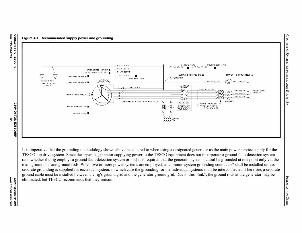
CH
AP
TE
R 4: S
YS
TE
M IN
SP
EC
TIO
N A
ND
ST
AR
TU
PIN
ST
ALLA
TIO
N G
UID
E
CO
NT
AC
T: 1-87
7-T
ES
CO
-77
350/400 TO
N E
XI 600H
PW
WW
.TE
SC
OC
OR
P.CO
M
INT
L: 713
-359
-729
535
WW
W.T
ES
CO
PA
RT
S.CO
M
It is imperative that the grounding methodology shown above be adhered to when using a designated generator as the main power service supply for the TESCO top drive system. Since the separate generator supplying power to the TESCO equipment does not incorporate a ground fault detection system (and whether the rig employs a ground fault detection system or not) it is required that the generator system neutral be grounded at one point only via the main ground bus and ground rods. When two or more power systems are employed, a “common system grounding conductor” shall be installed unless separate grounding is supplied for each such system, in which case the grounding for the individual systems shall be interconnected. Therefore, a separate ground cable must be installed between the rig's ground grid and the generator ground grid. Due to this “link”, the ground rods at the generator may be eliminated, but TESCO recommends that they remain.
Figure 4-1: Recommended supply power and grounding

INSTALLATION GUIDE CHAPTER 4: SYSTEM INSPECTION AND START UP
CONTACT: 1-877-TESCO-77 350/400 TON EXI 600HP WWW.TESCOCORP.COM
INTL: 713-359-7295 36 WWW.TESCOPARTS.COM
Other
• Ensure the gearbox breather is installed and the ball valve is opened prior to operating.Note: The breather may not be installed for shipping purposes and some new units may have the ball valve handle wired closed.
• Close the main breaker MB4 to turn the hydraulic tank heater on. When the temperature reaches 10ºC, the heating circuit will shut off automatically.
• Ensure that all electrical components are free of frost and condensation before system start up. Do this by opening all cabinet doors inside the power module and heating the building to at least 50F (10C) for eight hours. 208V power is required to operate the building HVAC unit.
• Install a saver sub in the grabber on the top drive before testing for hydraulic leaks or operate any robotics function.
Caution: The hydraulic pump cannot be started if the Emergency Shut Down (E.S.D.) is activated (either of two red buttons: one on the driller’s panel and one on the door of the main panel control system).
• Before starting any pumps, ensure that all appropriate valves on tanks and pumps are open.
SYSTEM START UP
After completing all visual inspections, begin the system start up process. This section provides instructions on how to do the following:
• power up support systems• power up the drive system• test the robotics functions and operations of the top drive
Danger! The information presented in this section is a guide ONLY. It is not intended to replace complete training on the use of high voltage equipment.
Note: Refer to the electrical schematics supplied with the unit.
!
!

CHAPTER 4: SYSTEM INSPECTION AND START UP INSTALLATION GUIDE
CONTACT: 1-877-TESCO-77 350/400 TON EXI 600HP WWW.TESCOCORP.COM
INTL: 713-359-7295 37 WWW.TESCOPARTS.COM
Table of Circuit Breakers and Main Breakers
Refer to the electrical schematics for the unit to confirm breaker details.
Support Systems
How to Start the Generator (if supplied)
1. Ensure that all fuel and air connections are secure.
2. Ensure that the following are set to ‘OFF’.• main service interface breaker• all main drive breakers in the power module building• all switches
3. Check all oil and coolant levels. Ensure the generator battery is above 22V.
4. Ensure that the following are clear of any obstructions or protective packing material:• radiator• air intakes• exhaust
5. Ensure all cabling and controls are in good operating condition (no noticeable damage).
6. Engage the air starter for one short burst without starting the engine.Note: This ensures the engine is free to roll over.
7. Set the controls to Start, and start the engine.
8. When the engine is running, check the oil pressure and rpm.
Caution: Ensure the oil pressure and rpm are within normal operating parameters.
CB (circuit breakers) - 120/208 VAC Distribution Panel
Breaker Type and Number Function
CB1 Power module lighting
CB2 120 VAC control power
CB3 Power module receptacles
CB4 24 VDC power supply
CB5 Spare
CB9 Motor heater
CB12/14/16 Power module HVAC
MB (main breakers)
Breaker Type and Number Function
MB1 ACS800 drive system power
MB2 Tie breaker
MB3 (in 600V distribution panel) 15kVA 600:120/208 VAC transformer
MB4 (in 600V distribution panel) Hydraulic tank heater
!
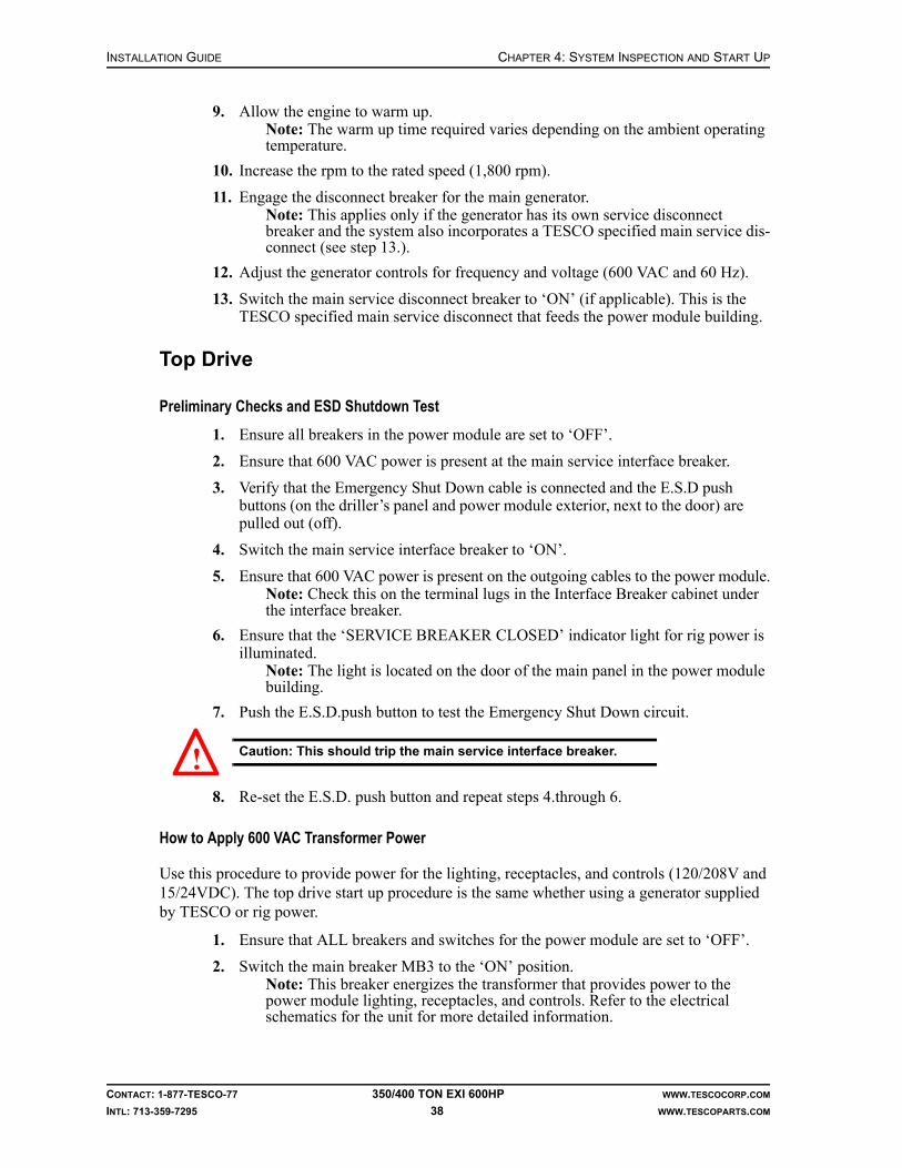
INSTALLATION GUIDE CHAPTER 4: SYSTEM INSPECTION AND START UP
CONTACT: 1-877-TESCO-77 350/400 TON EXI 600HP WWW.TESCOCORP.COM
INTL: 713-359-7295 38 WWW.TESCOPARTS.COM
9. Allow the engine to warm up.Note: The warm up time required varies depending on the ambient operating temperature.
10. Increase the rpm to the rated speed (1,800 rpm).
11. Engage the disconnect breaker for the main generator.Note: This applies only if the generator has its own service disconnect breaker and the system also incorporates a TESCO specified main service dis-connect (see step 13.).
12. Adjust the generator controls for frequency and voltage (600 VAC and 60 Hz).
13. Switch the main service disconnect breaker to ‘ON’ (if applicable). This is the TESCO specified main service disconnect that feeds the power module building.
Top Drive
Preliminary Checks and ESD Shutdown Test
1. Ensure all breakers in the power module are set to ‘OFF’.
2. Ensure that 600 VAC power is present at the main service interface breaker.
3. Verify that the Emergency Shut Down cable is connected and the E.S.D push buttons (on the driller’s panel and power module exterior, next to the door) are pulled out (off).
4. Switch the main service interface breaker to ‘ON’.
5. Ensure that 600 VAC power is present on the outgoing cables to the power module.Note: Check this on the terminal lugs in the Interface Breaker cabinet under the interface breaker.
6. Ensure that the ‘SERVICE BREAKER CLOSED’ indicator light for rig power is illuminated.
Note: The light is located on the door of the main panel in the power module building.
7. Push the E.S.D.push button to test the Emergency Shut Down circuit.
Caution: This should trip the main service interface breaker.
8. Re-set the E.S.D. push button and repeat steps 4.through 6.
How to Apply 600 VAC Transformer Power
Use this procedure to provide power for the lighting, receptacles, and controls (120/208V and 15/24VDC). The top drive start up procedure is the same whether using a generator supplied by TESCO or rig power.
1. Ensure that ALL breakers and switches for the power module are set to ‘OFF’.
2. Switch the main breaker MB3 to the ‘ON’ position.Note: This breaker energizes the transformer that provides power to the power module lighting, receptacles, and controls. Refer to the electrical schematics for the unit for more detailed information.
!

CHAPTER 4: SYSTEM INSPECTION AND START UP INSTALLATION GUIDE
CONTACT: 1-877-TESCO-77 350/400 TON EXI 600HP WWW.TESCOCORP.COM
INTL: 713-359-7295 39 WWW.TESCOPARTS.COM
3. Inside the 120/208V distribution panel, switch the following circuit breakers to the ‘ON’ position:• CB1 (power module lighting)• CB2 (120 VAC control power)• CB3 (power module receptacles)• CB4 (24 VDC power supply)• CB9 (motor heater)• CB12/14/16 (power module HVAC)
4. Set the light switch to the ‘ON’ position.Note: This switch is located on the wall of the power module .
5. Proceed to the following section: “Power up the Drive System”.
Power up the Drive System
1. Verify that the ESD on the driller’s panel is not activated.
2. Close the main breaker MB1 in the main drive cabinet to power up the drive system. To close MB1:• Ensure that the breaker switch is fully reset by pushing it down to the ‘OPEN’
position.• Push the breaker switch up to the ‘CLOSED’ position.
3. Push the blue RESET button on the front of the drive cabinet to clear any warning or faults in the drive.
4. On the left side of driller’s panel, turn the ENABLE switch to ‘OFF’.
5. Press the RESET button on the left side of driller’s panel to reset PLC communication.
6. Ensure that the green ‘READY’ light on the driller’s panel illuminates.
7. Proceed to the following section: “How to Check Phase Rotation”.
How to Check Phase Rotation
Use this procedure to ensure that the phase rotation is correct, and that all pumps, fans, and motors turn in the proper direction. Do not use pump motors to check phase rotation.
1. Switch motor starter 2M and 3M to ‘ON’.
2. Make sure all switches on driller’s panel are set to neutral position.
3. Turn the ENABLE switch to ‘ON’.
4. Set the ‘Set Speed’ and ‘Set Torque’ to zero using SPEED DECR and TORQUE DECR switch.
5. Ensure that the top drive is not rotating.
6. Ensure that the blower motor for the top drive rotates counter-clockwise when viewed from above.
7. Turn the QUILL switch back to neutral position.
8. If the direction of the blower motor is incorrect, do the following:
a. Shut off the main breaker MB1 and shut off the power at the main service breaker.
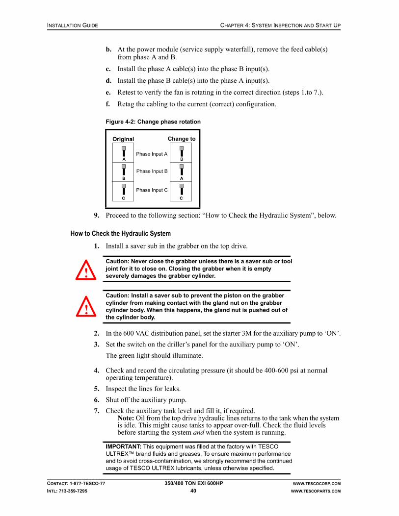
INSTALLATION GUIDE CHAPTER 4: SYSTEM INSPECTION AND START UP
CONTACT: 1-877-TESCO-77 350/400 TON EXI 600HP WWW.TESCOCORP.COM
INTL: 713-359-7295 40 WWW.TESCOPARTS.COM
b. At the power module (service supply waterfall), remove the feed cable(s) from phase A and B.
c. Install the phase A cable(s) into the phase B input(s).
d. Install the phase B cable(s) into the phase A input(s).
e. Retest to verify the fan is rotating in the correct direction (steps 1.to 7.).
f. Retag the cabling to the current (correct) configuration.
9. Proceed to the following section: “How to Check the Hydraulic System”, below.
How to Check the Hydraulic System
1. Install a saver sub in the grabber on the top drive.
Caution: Never close the grabber unless there is a saver sub or tool joint for it to close on. Closing the grabber when it is empty severely damages the grabber cylinder.
Caution: Install a saver sub to prevent the piston on the grabber cylinder from making contact with the gland nut on the grabber cylinder body. When this happens, the gland nut is pushed out of the cylinder body.
2. In the 600 VAC distribution panel, set the starter 3M for the auxiliary pump to ‘ON’.
3. Set the switch on the driller’s panel for the auxiliary pump to ‘ON’.
The green light should illuminate.
4. Check and record the circulating pressure (it should be 400-600 psi at normal operating temperature).
5. Inspect the lines for leaks.
6. Shut off the auxiliary pump.
7. Check the auxiliary tank level and fill it, if required.Note: Oil from the top drive hydraulic lines returns to the tank when the system is idle. This might cause tanks to appear over-full. Check the fluid levels before starting the system and when the system is running.
IMPORTANT: This equipment was filled at the factory with TESCO ULTREX™ brand fluids and greases. To ensure maximum performance and to avoid cross-contamination, we strongly recommend the continued usage of TESCO ULTREX lubricants, unless otherwise specified.
Figure 4-2: Change phase rotation
Phase Input A
Phase Input B
Phase Input C
A
B
C
Original
B
A
C
Change to
!
!

CHAPTER 4: SYSTEM INSPECTION AND START UP INSTALLATION GUIDE
CONTACT: 1-877-TESCO-77 350/400 TON EXI 600HP WWW.TESCOCORP.COM
INTL: 713-359-7295 41 WWW.TESCOPARTS.COM
How to Test the ESD on the Driller’s Panel
When activated, the ESD on the driller’s panel will trip the main breaker MB1 (which feeds the drive system) and turn off the auxiliary hydraulic pump.
1. Verify the main breaker MB1 is closed and the hydraulic pump is ‘ON’.
2. Press the ESD on the driller’s panel.
3. Verify that the main breaker MB1 has tripped.
4. Verify that the hydraulic pump has been turned off.
5. To reset the ESD, pull the button to the ‘UP’ position.
Final Start Up
When all critical systems are started and operating properly, the top drive can be started.
Before proceeding, confirm that all the following systems are operating correctly:
• cooling fans on the ACS800 drive cabinets• blower motor on the top drive
After confirming that all systems are operating correctly, perform the following steps:
1. Ensure that the ACS800 drive keypad display does not show any warnings or faults.
2. Check the indicators on the driller’s panel. The following lights should be on:• Ready• Module On
3. At the driller’s panel, set the ENABLE switch to ‘ON’.
4. Check the rotation and torque (at low settings) to confirm proper operation.
Caution: If using a customer-supplied swivel, it will not be properly connected to the top drive. Conduct operational checks at very low rpm, and only in the Forward setting. If rotating in reverse when the swivel is not fully connected, the swivel might unscrew at the connection with the top drive (and the top drive may fall to the rig floor).
How to Reset the ACS800 Drive
Use the following procedure if the ACS800 Drive System trips “off line” because an internal protection system has been activated. This procedure assumes that the system has sustained no damage and that supply power of 600 VAC is present.
1. Set all switches on the driller’s panel to the neutral position.
2. Turn the ENABLE switch on the driller's panel to the ‘OFF’ position (disable).
3. Ensure the following:• The communication between PLC and drive works properly• The encoder cable is securely connected• The fans for the top drive blower and drive cabinets work properly
!

INSTALLATION GUIDE CHAPTER 4: SYSTEM INSPECTION AND START UP
CONTACT: 1-877-TESCO-77 350/400 TON EXI 600HP WWW.TESCOCORP.COM
INTL: 713-359-7295 42 WWW.TESCOPARTS.COM
4. Check the fault information shown on the drive keypad and refer to the “Fault Tracking” section on page 223 of the ACS800 Firmware manual.
5. Press the RESET button on the ACS800 drive to reset faults after the faulty conditions have been removed.
6. Return to the driller’s panel and turn the ENABLE switch to the ‘ON’ position. The green READY light will illuminate.
7. Continue with regular operations.
8. Attempt to determine why the unit tripped off line. Make note of all relevant drilling conditions that existed before the breakers tripped.
Drive Parameters
About Drive Parameters
The following drive parameters (torque and speed settings) can be modified from the driller’s panel:
• Drill Forward – Torque and Speed• Drill Reverse – Torque and Speed• Connect Forward – Torque and Speed• Connect Reverse – Torque and Speed• Breakout – Speed
Set the drive parameters (torque and speed) to minimize the possibility of injury to personnel and damage to drilling equipment. For example, limit the torque setting for Drill–Forward mode to prevent the drill string twisting off while drilling. Set the speed and torque for Connect mode to promote proper make up of tool joints and to prevent damage to threads and seal faces caused by over-torquing.
Limit the rotation speed and torque of the pipe handler to ensure the pipe handler rotates at a safe speed and stops rotating when it achieves the pre-set torque.
The drive system will not surpass the programmed torque and speed settings during operation. If the settings need to be changed, use the following procedure. The steps required to set or adjust a setting are the same for all functions.
How to Modify Drive Parameters
1. At the driller’s panel, turn the ENABLE switch to ‘OFF’.
2. Insert the key into the DRIVE SET keyed switch.
3. Turn and hold the key in the ‘SET’ position.
4. Select and set the required function using Table 4-1 on page 43.
5. Release the DRIVE SET keyed switch.
6. Remove the key.
7. Set the ENABLE switch to ‘ON’.

CHAPTER 4: SYSTEM INSPECTION AND START UP INSTALLATION GUIDE
CONTACT: 1-877-TESCO-77 350/400 TON EXI 600HP WWW.TESCOCORP.COM
INTL: 713-359-7295 43 WWW.TESCOPARTS.COM
Table 4-1: Setting drive functions
To set this Perform these steps
Drill Forward Torque
1. Set the MODE switch to ‘DRILL’. 2. Set the QUILL switch to ‘FWD’. 3. Use the TORQUE switch to increase or decrease the SET TORQUE
reading on the digital gauge on the driller’s panel. Set this limit at 2,000 ft-lb less than the lowest connected joint torque setting (see Connect–Forward Torque). Consult with the Rig Manager or Oil Company Representative to determine the proper setting. If using a downhole mud motor, the torque set limit must be higher than the maximum output of the mud motor. Refer to ‘Mud Motors in Slide Drilling Operations’ within the Operations Guide for the unit.
Drill Reverse Speed and Torque
1. Set the MODE switch to ‘DRILL’. 2. Set the QUILL switch to ‘REV’. 3. Use the SPEED switch to increase or decrease the SET SPEED reading
on the digital gauge on the driller’s panel.TESCO recommends 10 rpm or less.
4. Use the TORQUE switch to increase or decrease the SET TORQUE reading on the digital gauge on the driller’s panel.TESCO recommends 5,000 to 8,000 ft-lb or less, depending on drill string configuration.
Connect Forward Speed and Torque
1. Set the MODE switch to ‘CONN’. 2. Set the QUILL switch to ‘FWD’.3. Use the SPEED switch to increase or decrease the SET SPEED reading
on the digital gauge on the driller’s panel. TESCO recommends 15 rpm or less.
4. Use the TORQUE switch to increase or decrease the SET TORQUE reading on the digital gauge on the driller’s panel.Use the torque requirements for the drill string connections to determine this setting.
Connect Reverse Speed and Torque
1. Set the MODE switch to ‘CONN’. 2. Set the QUILL switch to ‘REV’.3. Use the SPEED switch to increase or decrease the SET SPEED reading
on the digital gauge on the driller’s panel.TESCO recommends 15 rpm or less.
4. Use the TORQUE switch to increase or decrease the SET TORQUE reading on the digital gauge on the driller’s panel.TESCO recommends 8,000 ft-lb or less.
Pipe Handler Forward Speed and Torque
1. Set the MODE switch to ‘CONN’.2. Set the QUILL switch to ‘FWD’.3. Push and hold the PIPE HANDLER ROTATE button.4. Use the SPEED switch to increase or decrease the SET SPEED reading
on the digital gauge on the driller’s panel.TESCO recommends 5 rpm.
5. Use the TORQUE switch to increase or decrease the SET TORQUE reading on the digital gauge on the driller’s panel.TESCO recommends 5,000 ft-lb or less.
Pipe Handler ReverseSpeed and Torque
1. Set the MODE switch to ‘CONN’.2. Set the QUILL switch to ‘REV’.3. Push and hold the PIPE HANDLER ROTATE button.4. Use the SPEED switch to increase or decrease the SET SPEED reading
on the digital gauge on the driller’s panel.TESCO recommends 5 rpm.
5. Use the TORQUE switch to increase or decrease the SET TORQUE reading on the digital gauge on the driller’s panel.TESCO recommends 5,000 ft-lb or less.

INSTALLATION GUIDE CHAPTER 4: SYSTEM INSPECTION AND START UP
CONTACT: 1-877-TESCO-77 350/400 TON EXI 600HP WWW.TESCOCORP.COM
INTL: 713-359-7295 44 WWW.TESCOPARTS.COM
This page has been left blank intentionally.

CHAPTER 5: RIG OUT PROCEDURE INSTALLATION GUIDE
CONTACT: 1-877-TESCO-77 350/400 TON EXI 600HP WWW.TESCOCORP.COM
INTL: 713-359-7295 45 WWW.TESCOPARTS.COM
CHAPTER 5: RIG OUT PROCEDURE
The top drive rig-out (removal) procedure is divided into the following separate activities:
• remove the top drive• remove the torque arrest system• remove the service loop• prepare the power module and auxiliary hydraulic power unit
When the rig-out procedures are complete, store all equipment in shipping containers. For more information on long term storage, please consult the Maintenance Guide for the unit type.
REMOVE THE TOP DRIVE
1. Move the top drive handling frame to the rig floor.
2. Locate a pin position on the torque track and pin the torque bushing to the torque track.
Note: This pin connection holds the torque bushing in place when it is disconnected from the top drive.
3. Set the swivel link locks (turn buckles).
Figure 5-1: Setting the swivel link locks

INSTALLATION GUIDE CHAPTER 5: RIG OUT PROCEDURE
CONTACT: 1-877-TESCO-77 350/400 TON EXI 600HP WWW.TESCOCORP.COM
INTL: 713-359-7295 46 WWW.TESCOPARTS.COM
4. Disconnect the top drive from the extend frame.
5. Hoist the top drive.
6. Position the top drive handling frame over the hole center.
7. Lower the top drive into the handling frame and pin it in place.
8. Disconnect all service loop items from the top drive.
9. Remove the top drive from the rig floor.
Caution: Connect the hoisting cable to the top drive handling frame and not to any part of the top drive or yoke.
REMOVE THE TORQUE ARREST SYSTEM
This procedure assumes that the top drive is disconnected from the swivel and removed from the rig floor.
Note: If intending to reinstall the top drive into the existing mast, leave the torque track stabilization equipment in place. If there are no plans to reinstall the top drive, remove the stabilization equipment when lowering the mast.
1. Connect the tugger to the torque bushing and extend frame. Take the weight of the load with the tugger.
Note: The bushing will be pinned near the bottom of the torque track.
2. Remove the pin and carefully lower the torque bushing off the bottom of the torque track and onto the rig floor.
3. Use the tugger to move the bushing out the V-door.
4. Run two torque track handling slings through the becket of the blocks.
5. Attach the handling assembly of the torque track to the slings.
6. Raise the blocks to the crown.
7. Connect the torque track to the blocks by placing the handling assembly of the torque track through the hole in the torque track. Then, attach the slings to both sides of the handling assembly.
8. With the slings and pick-up pin in position, hoist the blocks to transfer the weight of the torque track from the torque track hanging assembly to the block slings.
9. Unbolt the T-bar from the torque track.
10. Loosen the T-bar clamp.
11. Slide the T-bar to its most rearward position.Note: This prevents the T-bar from obstructing the torque track during disassembly.
12. Re-tighten two bolts on the T-bar clamp.
13. Disconnect the hanging assembly from the pad eye in the crown.
14. Use the blocks to lower the torque track through the rotary table until the first flanged connection is at working height.
!

CHAPTER 5: RIG OUT PROCEDURE INSTALLATION GUIDE
CONTACT: 1-877-TESCO-77 350/400 TON EXI 600HP WWW.TESCOCORP.COM
INTL: 713-359-7295 47 WWW.TESCOPARTS.COM
15. Use a 4-3/4 ton shackle through the stabilizer attachment bar (on the back of the torque track) to attach the rig tugger to the bottom section of track. This will hold it in place while it is unbolted.
Caution: If a wellhead is not installed, ensure that the casing bowl is covered to prevent objects from falling into the hole.
16. Hoist the remaining track (suspended from the blocks) 10 to 15 ft (3 to 4.6 m) above the rig floor.
17. Use the rig tugger (already attached) to lift the bottom section of track out of the rotary table and off the rig floor.
18. Repeat steps 14.-17. for each section of torque track.
19. Remove the handling slings from the blocks and hoist the blocks clear of the rig floor.
20. Connect the tugger line to the T-bar/torque anchor beam.
21. Loosen and remove the anchor beam clamps.
22. Use the tugger to lower the T-bar/torque anchor beam and move it off the rig floor.
REMOVE THE SERVICE LOOP
Use the following procedure if the service loop is not strung through the mast and hangs off from a cable/hose saddle.
1. Position the cable storage reel in a convenient location for spooling.Note: There should be straight-line access from the reel to the cable/hose saddle.
2. Disconnect all service cables and hoses from the plug board on the power unit and auxiliary hydraulic power unit.
3. Move the disconnected ends to the storage reel.Note: Clean and protect cable and hose ends.
4. Attach the tugger line to the cable/hose saddle.
5. Disconnect the cable/hose saddle from the mast.
6. Connect the hydraulic control lines from the auxiliary hydraulic power unit to the storage reel.
7. Begin to spool the cables and hoses onto the reel.
8. When all the slack is taken up, lower the cable/hose saddle while continuing to spool.
9. Stop spooling when the cable/hose saddle reaches the storage reel.
10. Mark the location of the cable/hose saddle on the hoses with tape or paint.
11. Remove the cable/hose saddle from the service loop.
12. Spool the remainder of the service loop onto the storage reel.
!

INSTALLATION GUIDE CHAPTER 5: RIG OUT PROCEDURE
CONTACT: 1-877-TESCO-77 350/400 TON EXI 600HP WWW.TESCOCORP.COM
INTL: 713-359-7295 48 WWW.TESCOPARTS.COM
Use the following procedure if the service loop is strung through the mast and over a roller saddle, refer to Figure 5-2 on page 49.
1. Position the cable storage reel in a convenient location for spooling and connect the hydraulic lines from the auxiliary hydraulic power unit to the storage reel.
Note: There should be a straight line from the reel to the cable/hose saddle.
2. Disconnect all service cables from the plug board on the power unit.
3. Disconnect the auxiliary hydraulic hoses from the auxiliary power unit.
4. Move the disconnected ends to the storage reel.Note: Clean and protect the cable and hose ends.
5. Bundle the other end of the service loop (cables and hoses), that was disconnected from the top drive, together with a soft sling.
6. Attach a tugger line to the cable/hose saddle.
7. Attach a second tugger line to the service loop, approximately one third of the distance from the end of the service loop to the cable/hose saddle.
8. Hoist the second tugger line until the end that is attached to the service loop is horizontal with the cable/hose saddle.
9. Hoist both tugger lines until the free end of the service loop is just below the area where the service loop is strung through the mast structure.
10. String the free end of the service loop back through the mast structure.
11. Slowly lower both the tugger lines and begin to spool the cables and hoses onto the storage reel
Note: Watch the service loop as it is lowered through the mast structure so that it does not hang up or get snagged on the mast.
12. Lower both the tugger lines until the whole service loop is lowered to the drill floor.
13. Mark the location of the cable/hose saddle on the hoses and cables with tape or paint. These markings can be used to reposition the cable/hose saddle when the service loop is reinstalled.
14. Remove the cable/hose saddle from the service loop.
15. Spool the remainder of the service loop onto the storage reel.

CHAPTER 5: RIG OUT PROCEDURE INSTALLATION GUIDE
CONTACT: 1-877-TESCO-77 350/400 TON EXI 600HP WWW.TESCOCORP.COM
INTL: 713-359-7295 49 WWW.TESCOPARTS.COM
Figure 5-2: Spooling the service loop 1
INSTALLATION GUIDE CHAPTER 5: RIG OUT PROCEDURE
CONTACT: 1-877-TESCO-77 350/400 TON EXI 600HP WWW.TESCOCORP.COM
INTL: 713-359-7295 50 WWW.TESCOPARTS.COM
DISCONNECT THE POWER AND AUXILIARY HYDRAULIC POWER UNIT
1. Lock out the main breaker.
2. Disconnect the power to the power module.
3. Bundle all power cables.Note: Clean and protect all connectors.
4. Remove the Emergency Shut Down cable from the power module.
5. Remove and manually spool the hydraulic hoses that are connected to the cable storage reel.

APPENDIX A: PRE-INSTALLATION CHECKLIST INSTALLATION GUIDE
CONTACT: 1-877-TESCO-77 350/400 TON EXI 600HP WWW.TESCOCORP.COM
INTL: 713-359-7295 51 WWW.TESCOPARTS.COM
APPENDIX A: PRE-INSTALLATION CHECKLIST
Use the following checklist to check for possible damage during shipment before beginning installation procedures.
Component Description Date Initials
Containers Containers 1, 2, and 3 and 4 (if required)
Top Drive Travel stand
Top drive guard
Pipe Handler
Gearbox
Gearbox oil level
Top Drive cables and hoses
Auxiliary system (10-Station Manifold and solenoids)
Encoder
Mudsaver valve
Link Tilt cylinders
Power Module Drive Data Manager
Dynamic braking unit and braking resistors
15kVA, 600: 120/208V transformer
HVAC unit
600V distribution panel
120/208V distribution panel
Auxiliary Hydraulic Unit
Pump, and sensor wiring
Systems fittings and hoses
Auxiliary pump and motor
Filter housings
Pump quick connect fittings
Hydraulic reservoir
Service Loop Roller saddle and capture clamp
Urethane inserts
Hose reel
Hose reel control
Slings, shackles, and safety pins

INSTALLATION GUIDE APPENDIX A: PRE-INSTALLATION CHECKLIST
CONTACT: 1-877-TESCO-77 350/400 TON EXI 600HP WWW.TESCOCORP.COM
INTL: 713-359-7295 52 WWW.TESCOPARTS.COM
Hoses Hose reel
1×225 ft auxiliary return hose
1×225 ft auxiliary supply hose
2×35 ft auxiliary jumper hoses
Main Power Cables
1× 4/0 ground cable, 225 ft long
1 x 225 ft #14.7C motor blower cable
3 x 313 MCM 225 ft cables
Other Cables 1×225 ft 37-conductor robotics control cable
1×225 ft motor sensor feedback cable
1×150 ft 4TWP driller’s panel instrumentation Cable B
1×150 ft 18/4 emergency shutdown cable (if required)
2×8 ft 18/4 mub pump interlock cable
2×8 ft 18/4 drawworks interlock cable
2×8 ft 18/4 splitter box cable
1x 29 ft #14.7C pump skid power cable
1 x 29 ft #18.4 pump skid sensor cable
Driller’s Panel Instrumentation
Switches
Connectors
Internal wiring
Auxiliary Hoses 1 x 225 ft auxiliary return hose (1-1/4 in.)
1 x 225 ft auxiliary supply hose (3/4 in.)
2 x 10 ft auxiliary jumper hoses (1 in. - R2)
Torque Arrest System
Extend frame
Torque bushing
Torque beam and T-bar
Torque track
Hanging sling assembly
Accessories (if purchased)
Main service interface breaker
Crimping tool (if required)
Counter-balance system
Elevators
Elevator inserts
Elevator links
Saver subs
Component Description Date Initials

APPENDIX B: VISUAL INSPECTION CHECKLISTS INSTALLATION GUIDE
CONTACT: 1-877-TESCO-77 350/400 TON EXI 600HP WWW.TESCOCORP.COM
INTL: 713-359-7295 53 WWW.TESCOPARTS.COM
APPENDIX B: VISUAL INSPECTION CHECKLISTS
Use this checklist after installation procedures are complete, but before starting the system.
Danger! Before proceeding with the checklists ensure that all power to the top drive is shut off and locked out.
Danger! Only qualified electrical personnel should check electrical equipment.
IMPORTANT: This equipment was filled at the factory with TESCO ULTREX brand fluids and greases. To ensure maximum performance and to avoid cross-contamination, we strongly recommend the continued usage of TESCO ULTREX lubricants, unless otherwise specified.
Table B-1: Top drive inspection list
Component Activity Steps
Sensors and Wiring
Inspect the sensors and wiring. 1. Open the motor junction box. Open the sensor/robotics panel.
2. Inspect the wiring to the following:• Encoder• RTDs• Pressure switchNote: Look for damage to wiring and ensure all the connections are tight.
3. Replace the desiccant pack if necessary.
Motor Cabling Check the motor cabling. 1. Remove the access covers on the junction boxes.
2. Check wiring to the drive motor. 3. Check for cable discoloration (as a result of heat-
damage).4. Ensure that motor lugs and other terminations
are tight.5. Ensure the junction box gaskets are in good con-
dition and will seal properly.6. Restore the access covers to their original posi-
tion on the junction box.
Robotics Inspect the listed components. 1. 10-Station manifold2. Solenoids and wiring3. Auxiliary hydraulic hosing4. 37C control cable5. All fittings (for tightness and correct engagement)
Gearbox Inspect the listed items. 1. Check for leaks.2. Check the oil level.
Top Drive Hoses Check the auxiliary hydraulic hoses and gearbox lubrication hoses.
1. Inspect all hoses including service loop.2. Tighten the fittings as necessary.
!
!

INSTALLATION GUIDE APPENDIX B: VISUAL INSPECTION CHECKLISTS
CONTACT: 1-877-TESCO-77 350/400 TON EXI 600HP WWW.TESCOCORP.COM
INTL: 713-359-7295 54 WWW.TESCOPARTS.COM
Lubrication Ensure lubrication is adequate. 1. Grease all lubrication points.2. Check and verify the slew drive is properly
greased.
Quill Inspect the listed components. 1. Quill2. Load nut and locking pins3. Mudsaver4. Load collar stops (set)5. Saver sub6. Locking clamps
Grabber Inspect the listed components. 1. The safety chain is installed.2. All drilled bolts are safety wired.3. Hoses are installed and routed correctly.
Extend Frame Mount
Inspect all pins and bolts. 1. Check for missing fasteners.2. Check the ears on the extend frame for damage.
Table B-2: Power module inspection list
Component Activity Steps
Wiring Check all power module wiring. 1. Check connections for damage or decay. Tighten if required.Note: Ensure that connections are properly torqued.
2. Check the AC feed connections.3. Check the switch & breaker wiring.
Breakers Check that the trip voltage is set correctly for all main breakers.
1. Verify the breaker UV trip voltage.2. Verify the breaker current trip level.
Plugboard (Waterfall)
Check all connections. 1. Check the motor leads from the drive to the plug-board.
Table B-3: Auxiliary hydraulic power unit inspection list
Component Activity Steps
Wiring Systems Checl all electrical wiring to the Auxiliary Hydraulic Power Unit
Check the following cord ends for condition and cleanliness:
• power cables
Fluid Systems Check hydraulic systems 1. Check the following for condition, cleanliness, and tightness:• auxiliary hydraulics system fittings
2. Ensure tank drain valve is closed.3. Check hydraulic fluid level in reservoir.
Mechanical Check the mechanical components of the module
1. Check for proper rotation of the pump motor.
Valves Inspect Ensure all valves are set to the correct position.
Return Filters Inspect Ensure all filters are in place.
Table B-1: Top drive inspection list
Component Activity Steps

APPENDIX B: VISUAL INSPECTION CHECKLISTS INSTALLATION GUIDE
CONTACT: 1-877-TESCO-77 350/400 TON EXI 600HP WWW.TESCOCORP.COM
INTL: 713-359-7295 55 WWW.TESCOPARTS.COM
Table B-4: Cable reel/service loop inspection list
Component Activity Steps
Reel Lock Inspect Ensure the reel lock is locked into position.
Service Loop Protection
Inspect Ensure all wear points are protected and secure.
Service Loop Inspect cables and hoses. Inspect cables and hoses for the following:• cuts• abrasions• signs of stretching
Service Loop Terminations
Inspect connectors and fittings. 1. Inspect connectors for damage to the pins.2. Ensure that all pin connectors are correctly
seated.3. Check the threads on all brass fittings.4. Ensure that all connectors are clean and free of
moisture.
Table B-5: Driller’s panel
Component Activity Steps
Driller’s Panel Inspect panel and connectors. 1. Inspect all switches.2. Ensure all switches are in the neutral position.3. Inspect all instrumentation.4. Inspect all connectors.5. Ensure that all the cords are operational.

INSTALLATION GUIDE APPENDIX B: VISUAL INSPECTION CHECKLISTS
CONTACT: 1-877-TESCO-77 350/400 TON EXI 600HP WWW.TESCOCORP.COM
INTL: 713-359-7295 56 WWW.TESCOPARTS.COM
This page has been left blank intentionally.

APPENDIX C: SLING LOAD RATINGS INSTALLATION GUIDE
CONTACT: 1-877-TESCO-77 350/400 TON EXI 600HP WWW.TESCOCORP.COM
INTL: 713-359-7295 57 WWW.TESCOPARTS.COM
APPENDIX C: SLING LOAD RATINGS
Table values below are for slings with eyes and thimbles in both ends, as well as Flemish Spliced Eyes and mechanical sleeves.
Caution: Reduce loads if hand-tucked spliced eyes are used.
Reduce loads by 20% if eyes are formed by cable clips.
Table C-1: Maximum safe working loads (pounds)
Safety Factor = 5
Rope Diameter
Single Vertical Hitch
Single Choker Hitch
Single Basket Hitch (vertical legs)
2-leg Bridle Hitch and Single Basket Hitch with legs included
60 in. 45 in. 30 in.
3/16 600 450 1,200 1,050 850 600
¼ 1,100 825 2,200 1,900 1,550 1,100
5/16 1,650 1,250 3,300 2,850 2,350 1,650
3/8 2,400 1,800 4,800 4,150 3,400 2,400
7/16 3,200 2,400 6,400 5,550 4,500 3,200
½ 4,400 3,300 8,800 7,600 6,200 4,400
9/16 5,300 4,000 10,600 9,200 7,500 5,300
5/8 6,600 4,950 13,200 11,400 9,350 6,600
¾ 9,500 7,100 19,000 16,500 13,400 9,500
7/8 12,800 9,600 25,600 22,200 18,100 12,800
1 16,700 12,500 33,400 28,900 23,600 16,700
1 1/8 21,200 15,900 42,400 36,700 30,000 21,200
1 ¼ 26,200 19,700 52,400 45,400 37,000 26,200
1 3/8 32,400 24,300 64,800 56,100 45,800 32,400
1 ½ 38,400 28,800 76,800 66,500 54,300 38,400
1 5/8 45,200 33,900 90,400 78,300 63,900 45,200
1 ¾ 52,000 39,000 104,000 90,000 73,500 52,000
1 7/8 60,800 45,600 121,600 105,300 86,000 60,800
2 67,600 50,700 135,200 117,100 95,600 67,600
2 ¼ 84,000 63,000 168,000 145,500 118,800 84,000
2 ½ 104,000 78,000 208,000 180,100 147,000 104,000
!

INSTALLATION GUIDE APPENDIX C: SLING LOAD RATINGS
CONTACT: 1-877-TESCO-77 350/400 TON EXI 600HP WWW.TESCOCORP.COM
INTL: 713-359-7295 58 WWW.TESCOPARTS.COM
If using a choker hitch, multiply the previous table values by 3/4.
If using a double basket hitch, multiply the previous table values by 2.
2 ¾ 122,000 91,500 244,000 211,300 172,500 122,000
Table C-2: Rope diameter efficiencies
Rope Diameter Efficiency
1/4 in. and smaller 95%
5/16 to 3/4 in. 90%
7/8 to 1 in. 85%
1-1/8 to 1-1/2 in. 80%
1-5/8 to 2 in. 75%
2-1/8 in. and larger 70%
Table C-1: Maximum safe working loads (pounds)

APPENDIX D: HAND SIGNALS FOR BOOM EQUIPMENT OPERATION INSTALLATION GUIDE
CONTACT: 1-877-TESCO-77 350/400 TON EXI 600HP WWW.TESCOCORP.COM
INTL: 713-359-7295 59 WWW.TESCOPARTS.COM
APPENDIX D: HAND SIGNALS FOR BOOM EQUIPMENT OPERATION
The following chart contains examples of typical signals used by the signalman during boom equipment operations. If the project requires special signals, agree on what they will be before beginning operations.
Boom operators will not respond to unclear signals.
Designate one signalman before operation begins. The boom operator accepts signals only from the designated signalman.
Table D-1: Hand signals for boom operation
This Signal Means This
Use Load LineTap fist on head, then use regular signals.
Use Whip LineTab elbow with one hand, then use regular signals.
Raise Load
Lower Load
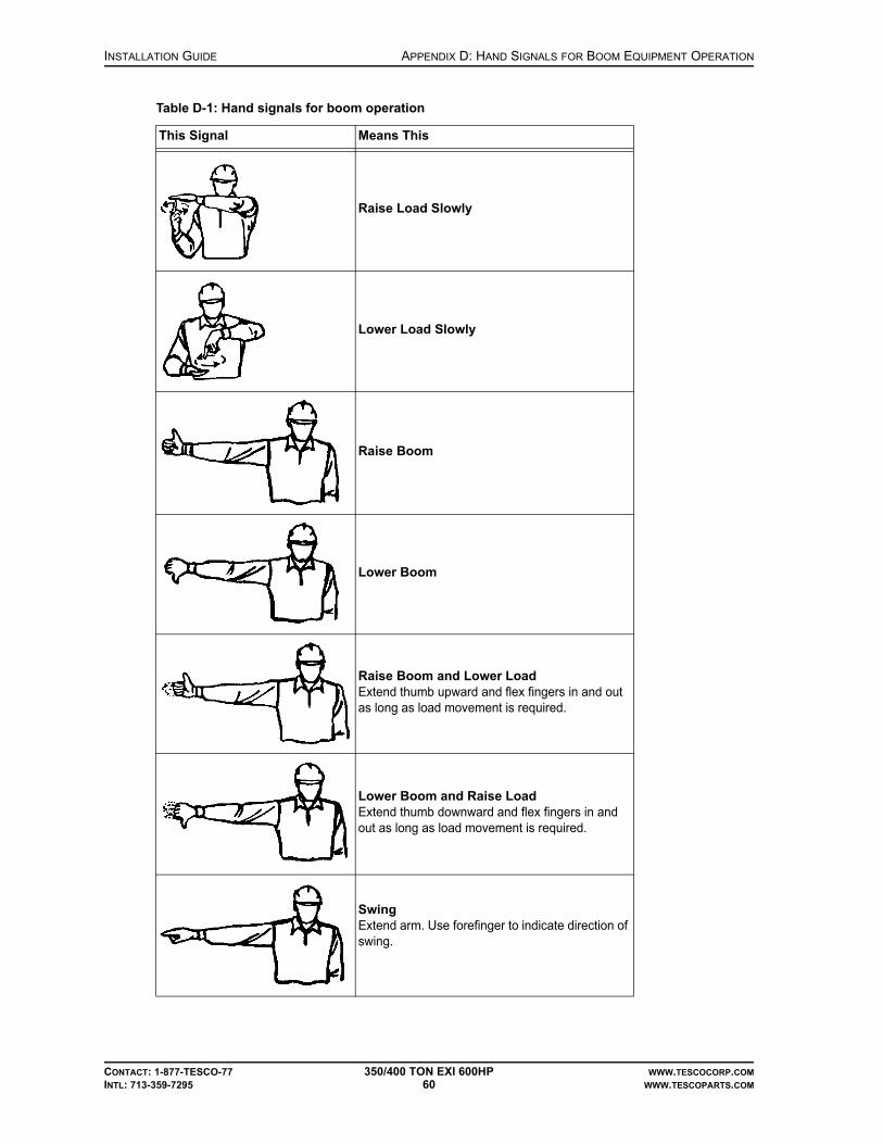
INSTALLATION GUIDE APPENDIX D: HAND SIGNALS FOR BOOM EQUIPMENT OPERATION
CONTACT: 1-877-TESCO-77 350/400 TON EXI 600HP WWW.TESCOCORP.COM
INTL: 713-359-7295 60 WWW.TESCOPARTS.COM
Raise Load Slowly
Lower Load Slowly
Raise Boom
Lower Boom
Raise Boom and Lower LoadExtend thumb upward and flex fingers in and out as long as load movement is required.
Lower Boom and Raise LoadExtend thumb downward and flex fingers in and out as long as load movement is required.
SwingExtend arm. Use forefinger to indicate direction of swing.
Table D-1: Hand signals for boom operation
This Signal Means This

APPENDIX D: HAND SIGNALS FOR BOOM EQUIPMENT OPERATION INSTALLATION GUIDE
CONTACT: 1-877-TESCO-77 350/400 TON EXI 600HP WWW.TESCOCORP.COM
INTL: 713-359-7295 61 WWW.TESCOPARTS.COM
StopExtend forearm and hand in horizontal position. Make a slicing motion.
Dog Everything
Emergency Stop
Travel (Both Tracks)Use both fists to make a circular motion to indicate the direction of travel (forward or backward).
Travel (One Track)Raise fist to indicate which side of the track to lock. Move the other fist in a circular motion to indicate the direction of travel (forward or backward)
Open Clamshell Bucket
Close Clamshell Bucket
Table D-1: Hand signals for boom operation
This Signal Means This

INSTALLATION GUIDE APPENDIX D: HAND SIGNALS FOR BOOM EQUIPMENT OPERATION
CONTACT: 1-877-TESCO-77 350/400 TON EXI 600HP WWW.TESCOCORP.COM
INTL: 713-359-7295 62 WWW.TESCOPARTS.COM
Move Carriage In
Move Carriage Out
Table D-1: Hand signals for boom operation
This Signal Means This

APPENDIX E: TRIP AND WARNING CODES INSTALLATION GUIDE
CONTACT: 1-877-TESCO-77 350/400 TON EXI 600HP WWW.TESCOCORP.COM
INTL: 713-359-7295 63 WWW.TESCOPARTS.COM
APPENDIX E: TRIP AND WARNING CODES
The following trip and warning codes come directly from the ABB ACS800 Firmware manual.

INSTALLATION GUIDE APPENDIX E: TRIP AND WARNING CODES
CONTACT: 1-877-TESCO-77 350/400 TON EXI 600HP WWW.TESCOCORP.COM
INTL: 713-359-7295 64 WWW.TESCOPARTS.COM

APPENDIX E: TRIP AND WARNING CODES INSTALLATION GUIDE
CONTACT: 1-877-TESCO-77 350/400 TON EXI 600HP WWW.TESCOCORP.COM
INTL: 713-359-7295 65 WWW.TESCOPARTS.COM
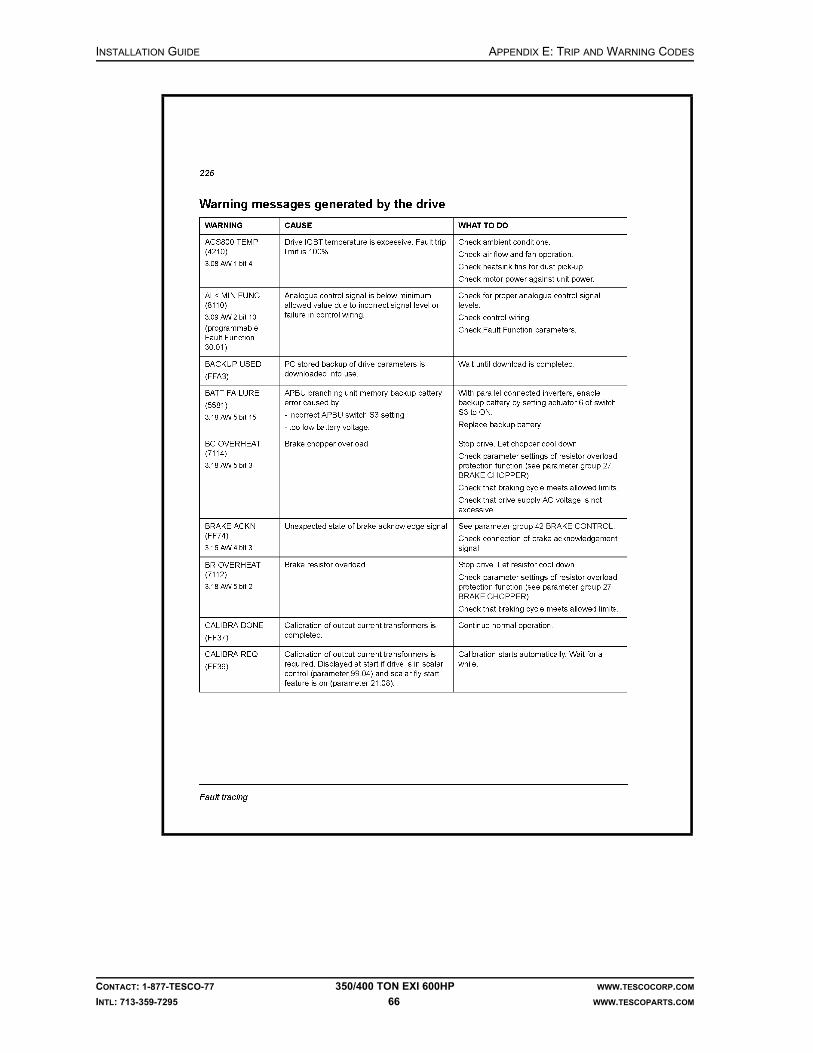
INSTALLATION GUIDE APPENDIX E: TRIP AND WARNING CODES
CONTACT: 1-877-TESCO-77 350/400 TON EXI 600HP WWW.TESCOCORP.COM
INTL: 713-359-7295 66 WWW.TESCOPARTS.COM

APPENDIX E: TRIP AND WARNING CODES INSTALLATION GUIDE
CONTACT: 1-877-TESCO-77 350/400 TON EXI 600HP WWW.TESCOCORP.COM
INTL: 713-359-7295 67 WWW.TESCOPARTS.COM

INSTALLATION GUIDE APPENDIX E: TRIP AND WARNING CODES
CONTACT: 1-877-TESCO-77 350/400 TON EXI 600HP WWW.TESCOCORP.COM
INTL: 713-359-7295 68 WWW.TESCOPARTS.COM

APPENDIX E: TRIP AND WARNING CODES INSTALLATION GUIDE
CONTACT: 1-877-TESCO-77 350/400 TON EXI 600HP WWW.TESCOCORP.COM
INTL: 713-359-7295 69 WWW.TESCOPARTS.COM

INSTALLATION GUIDE APPENDIX E: TRIP AND WARNING CODES
CONTACT: 1-877-TESCO-77 350/400 TON EXI 600HP WWW.TESCOCORP.COM
INTL: 713-359-7295 70 WWW.TESCOPARTS.COM

APPENDIX E: TRIP AND WARNING CODES INSTALLATION GUIDE
CONTACT: 1-877-TESCO-77 350/400 TON EXI 600HP WWW.TESCOCORP.COM
INTL: 713-359-7295 71 WWW.TESCOPARTS.COM

INSTALLATION GUIDE APPENDIX E: TRIP AND WARNING CODES
CONTACT: 1-877-TESCO-77 350/400 TON EXI 600HP WWW.TESCOCORP.COM
INTL: 713-359-7295 72 WWW.TESCOPARTS.COM

APPENDIX E: TRIP AND WARNING CODES INSTALLATION GUIDE
CONTACT: 1-877-TESCO-77 350/400 TON EXI 600HP WWW.TESCOCORP.COM
INTL: 713-359-7295 73 WWW.TESCOPARTS.COM
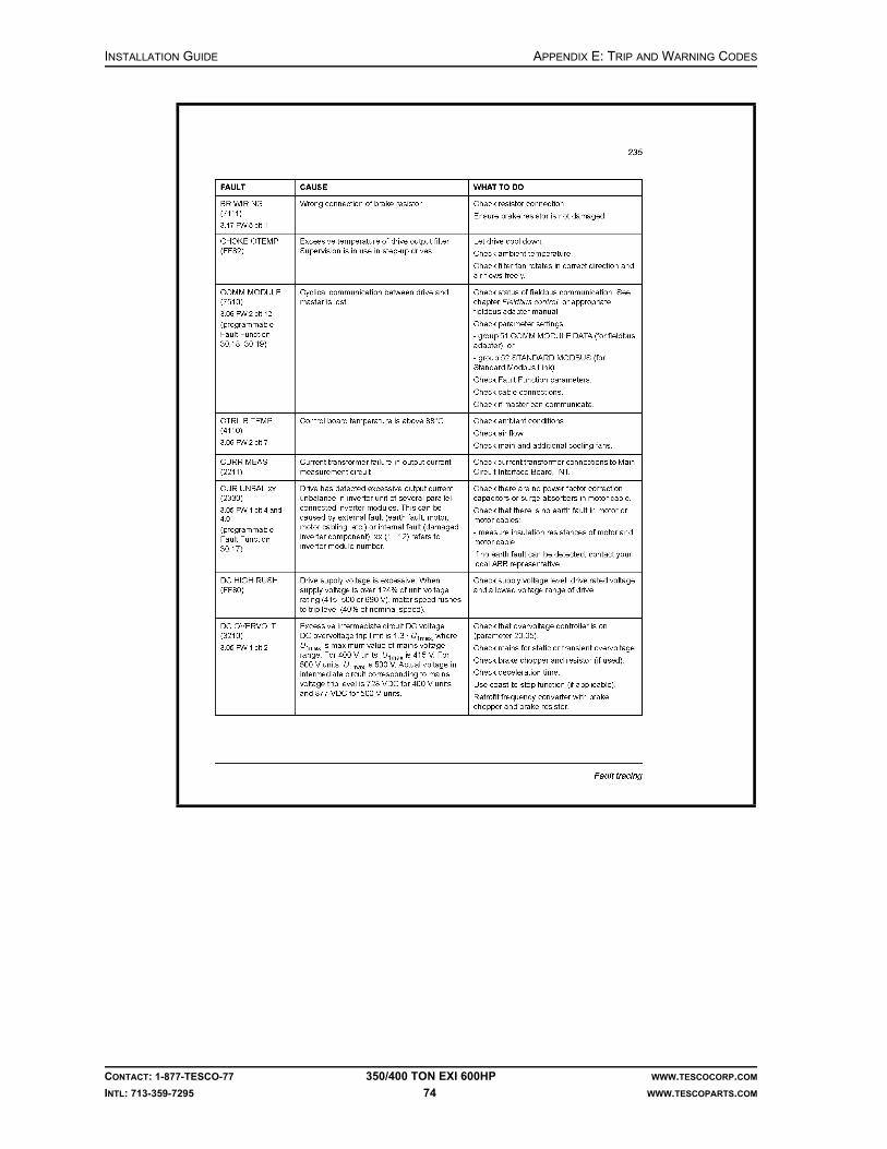
INSTALLATION GUIDE APPENDIX E: TRIP AND WARNING CODES
CONTACT: 1-877-TESCO-77 350/400 TON EXI 600HP WWW.TESCOCORP.COM
INTL: 713-359-7295 74 WWW.TESCOPARTS.COM

APPENDIX E: TRIP AND WARNING CODES INSTALLATION GUIDE
CONTACT: 1-877-TESCO-77 350/400 TON EXI 600HP WWW.TESCOCORP.COM
INTL: 713-359-7295 75 WWW.TESCOPARTS.COM

INSTALLATION GUIDE APPENDIX E: TRIP AND WARNING CODES
CONTACT: 1-877-TESCO-77 350/400 TON EXI 600HP WWW.TESCOCORP.COM
INTL: 713-359-7295 76 WWW.TESCOPARTS.COM
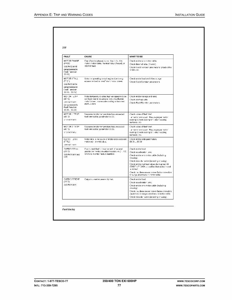
APPENDIX E: TRIP AND WARNING CODES INSTALLATION GUIDE
CONTACT: 1-877-TESCO-77 350/400 TON EXI 600HP WWW.TESCOCORP.COM
INTL: 713-359-7295 77 WWW.TESCOPARTS.COM

INSTALLATION GUIDE APPENDIX E: TRIP AND WARNING CODES
CONTACT: 1-877-TESCO-77 350/400 TON EXI 600HP WWW.TESCOCORP.COM
INTL: 713-359-7295 78 WWW.TESCOPARTS.COM
This page has been left blank intentionally.
APPENDIX F: TORQUE STANDARDS FOR HIGH STRENGTH FASTENERS INSTALLATION GUIDE
CONTACT: 1-877-TESCO-77 350/400 TON EXI 600HP WWW.TESCOCORP.COM
INTL: 713-359-7295 79 WWW.TESCOPARTS.COM
APPENDIX F: TORQUE STANDARDS FOR HIGH STRENGTH FASTENERS
The following information originated from the Standards document STD0015.
PURPOSE
This standard should be used as a guideline for all fasteners used in production where the torque values are not specified on the engineering documentation and drawings. All TESCO standards on fasteners should be adhered to, as non-conformance can lead to the following:
• low quality products• rework cost• warranty claims• late delivery• customer dissatisfaction• lower production
STANDARDS
1. All capscrews, bolts and nuts have to be Grade 8 or equivalent unless noted otherwise (U.N.O.).
2. Fasteners must be torqued in accordance with Table F-1, Table F-2, and Table F-3 U.N.O. Torques should be applied smoothly and with a calibrated wrench.
3. Multiple fastener arrays must be made up evenly using an appropriate torque sequence to minimize distortion. Fasteners shall be tightened using intermediate torque settings of 40% and 75% of values in the tables. All fasteners must be made up snug prior to starting the tightening sequence.
4. Fastener torques for bolting dissimilar materials must be based on the torque requirements for the lower strength material U.N.O.
5. Fasteners and holes should be free of burrs or damage. Damaged threads must be repaired using the appropriate tooling to ensure a free and smooth assembly.
6. When thread locking compound is used, holes and fasteners should be cleaned (free of oil or grease) and the compound should be applied in conformance with manufacturer’s recommendations.
7. Allowable bolt tension and torque based on bolt thread engagement must be in accordance with Table F-4 U.N.O.
8. Special fasteners must be installed and torqued in accordance with Table F-2.
9. When threadlock is used, fasteners must be torqued in accordance with Table F-1, Table F-2 and Table F-3, using the ‘Lubricated’ Torque data U.N.O.

INSTALLATION GUIDE APPENDIX F: TORQUE STANDARDS FOR HIGH STRENGTH FASTENERS
CONTACT: 1-877-TESCO-77 350/400 TON EXI 600HP WWW.TESCOCORP.COM
INTL: 713-359-7295 80 WWW.TESCOPARTS.COM
10. For torque values for B7 studs with 2H nuts, see Table F-3.
11. Lubricated fasteners must have oil or thread locking compound applied to the threads only.
12. Where metals with strongly varying electromotive properties are bolted together, such as steel and aluminum, thread locking compounds should be applied to limit the effects of galvanic corrosion.
13. A minimum of two full threads should project above any nut or locknut installed on a stud or as part of a bolted connection. Additional length is allowed to install safety pines or cotter pins to prevent fasteners from falling into overhead equipment.
TABLES
Table F-1: Standard torques
Material Aluminum (ft-lb) Mild Steel (ft-lb) High Strength Steel (ft-lb)
Size Dry Lubricated Dry Lubricated Dry Lubricated
1/4 in.-20 UNC 9 7 10 8 12 9
5/16 in.-18 UNC 16 12 19 15 25 19
3/8 in.-16 UNC 33 25 40 30 45 34
7/16 in.-14 UNC 47 36 57 43 70 53
1/2 in.-13 UNC 86 64 100 75 110 83
9/16 in.-12 UNC 118 88 141 106 160 120
5/8 in.-11 UNC 163 122 195 146 220 165
3/4 in.-10 UNC 278 209 333 250 400 300
7/8 in.-9 UNC 436 327 523 393 645 484
1 in.-8 UNC 667 500 800 600 970 728
1-1/8 in.-7 UNC 950 713 1142 856 1370 1028
1-1/4 in.-7 UNC 1317 988 1575 1181 1900 1425
1-1/2 in.-6 UNC 2283 1713 2742 2056 3200 2400
Recommended torques are based on bolt tensions of approximately 80% of the yield strength and a minimum of one bolt diameter class 2B thread engagement in the material, or bolt head bearing pressures, whichever is less.

APPENDIX F: TORQUE STANDARDS FOR HIGH STRENGTH FASTENERS INSTALLATION GUIDE
CONTACT: 1-877-TESCO-77 350/400 TON EXI 600HP WWW.TESCOCORP.COM
INTL: 713-359-7295 81 WWW.TESCOPARTS.COM
Table F-2: Special fastener torques
Fastener DescriptionMinimum
EngagementMild Steel (ft-lb) High Strength Steel (ft-lb)
Dry Lubricated Dry Lubricated
UNBRAKO 5/16 in.-18 UNRC 3/8 in. 27 20 35 26
UNBRAKO 1/2 in.-13 UNRC 1/2 in. 118 88 154 115
UNBRAKO 5/8 in.-11 UNRC 5/8 in. 217 162 283 212
Special fasteners shall be used only in critical locations or special applications. Thread engagement is based on the minimum class 2B tapped threads in mild steel capable of developing bolt tension 80% of bolt yield. When using hardened steel washers on mild steel, use torque values for high strength steel.
Table F-3: B7 Stud torques
Stud Size Dry (ft-lb) Lubricated (ft-lb)
1/2 in.-3 UNC 85 64
5/8 in.-11 UNC 175 131
3/4 in.-10 UNC 300 225
7/8 in.-9 UNC 450 338
1 in.-8 UNC 680 510
1-1/8 in.-7 UNC 880 660
1-1/4 in.-7 UNC 1260 945
1-3/8 in.-6 UNC 1700 1275
1-1/2 in.-8 UN 2300 1725
Recommended torques are based on bolt tensions of approximately 75% of stud yield strength.
Table F-4: Thread engagements
Material Aluminum Mild Steel High Strength Steel
Engagement* % of Full Torque % of Full Torque % of Full Torque
100% 100% 100% 100%
90% 100% 100% 100%
80% 100% 100% 100%
70% 100% 100% 100%
60% 90% 100% 100%
50% 70% 100% 100%
40% 60% 75% 100%
30% 45% 60% 75%
20% 30% 40% 55%
* Engagement as a % of the bolt diameterValues represent the percentage of torque from Table F-1. Engagement does not include chamfer or incomplete threads. Engagements of less than one bolt diameter in tapped holes shall not be used without the engineer’s approval.

INSTALLATION GUIDE APPENDIX F: TORQUE STANDARDS FOR HIGH STRENGTH FASTENERS
CONTACT: 1-877-TESCO-77 350/400 TON EXI 600HP WWW.TESCOCORP.COM
INTL: 713-359-7295 82 WWW.TESCOPARTS.COM
This page has been left blank intentionally.

INDEX INSTALLATION GUIDE
CONTACT: 1-877-TESCO-77 350TON EXI 600HP WWW.TESCOCORP.COM
INTL: 713-359-7295 83 WWW.TESCOPARTS.COM
INDEX
Numerics600VAC
applying power, 38
Aair considerations, 6air intakes, 37air starter, 37auxiliary hydraulic power unit
disconnecting, 50placement during rig up, 7
auxiliary pump, 40
Bbattery, 37blocks, 24
Ccable roller saddle
optimal placement, 9placement factors, 10placement procedure, 10
circuit breakers, 37coolant levels, 37counter balance system
installation, 30
Ddamage
pre-installation inspection, 6danger
electrical warnings, 34drawworks interlock and override
installation, 29driller’s panel
installation, 28drive parameters
connect reverse, 43drill forward torque, 43modifying, 42set connect forward, 43set drill reverse speed and torque, 43
Eelectrical
warnings, 34emergency shut down (E.S.D.), 36
equipmentinspecting, 6inspecting for damage, 6placement, 7placement during rig up, 7placement procedure, 8
equipment placementauxiliary hydraulic power unit, 7cable roller saddle, 9power module, 7service loop reel, 9
ESD testtop drive, 38
exhaust, 37
Ffinal start up, 41fuel considerations, 5
Ggenerator
controls, 38starting, 37
Hhigh strength fasteners, torque standards, 79hydraulic system
checking, 40
Iinspecting equipment
pre-installation, 6inspection
general notes, 33installation
pre-installation measurement, 3rig measurement, 3
Mmain breakers, 37main panel control system, 36measurement
rig, 3mud pump interlock, 30
Ooptimal placement

INSTALLATION GUIDE INDEX
CONTACT: 1-877-TESCO-77 350TON EXI 600HP WWW.TESCOCORP.COM
INTL: 713-359-7295 84 WWW.TESCOPARTS.COM
auxiliary hydraulic power unit, 7power module, 7
Pphase rotation
checking, 39power
checklist, 4connection requirements, 3supplying to equipment, 38
power moduledisconnecting, 50placement during rig up, 7placement procedure, 8
pre-installationinspection, 6main power connection requirements, 3main power requirements checklist, 4measurement, 3
Rradiator, 37rig out
disconnect auxiliary hydraulic power unit, 50disconnect power module, 50remove the service loop, 47remove the top drive, 45remove the torque arrest system, 46
rig upequipment placement, 7install safety air interlocks, 29install the counter-balance system, 31install the driller’s panel, 28install the service loop, 11install the top drive, 23install the torque arrest system, 16
Ssafety air interlocks
installation, 29saver sub, 36service loop
installation option 1, 11installation option 2, 13removing, 47
service loop reeloptimal placement, 9
speedset connect forward, 43set connect reverse, 43set drill reverse, 43
start upfinal phase, 41
support systemsstart up, 37
Ttop drive
adjusting the extend arm, 27installation, 23preliminary checks and ESD test, 38starting, 38
torqueset connect forward, 43set connect reverse, 43set drill forward, 43set drill reverse, 43
torque arrest systembefore installing, 16components, 17configuration sample calculation, 19determine the configuration, 17installation, 16removing, 45, 46torque track, 19
torque bushing, 24torque track
mounting, 19transformer power
applying, 38
Wwarnings
before start up, 34condensation, 36electrical, 34other, 36

INSTALLATION GUIDE
CONTACT: 1-877-TESCO-77 350/400 TON EXI 600HP WWW.TESCOCORP.COM
INTL: 713-359-7295 85 WWW.TESCOPARTS.COM
ENGINEERING SIGN-OFF
This sign-off sheet indicates that this document has been approved for release by the Engineering Department at TESCO.
Document Complete By Signature Date Signed
Document Reviewed/Approved Date Signed
chane
Typewritten Text
Edward ChanSept. 28, 2009
madejskm
Typewritten Text
Oct. 22, 2009

INSTALLATION GUIDE
CONTACT: 1-877-TESCO-77 350/400 TON EXI 600HP WWW.TESCOCORP.COM
INTL: 713-359-7295 86 WWW.TESCOPARTS.COM
This page has been left blank intentionally.

DOCUMENT NAME: 880078 REV 2
Operations Guide
EXI Top Drive System
350/400 TON EXI 600HP

COPYRIGHT AND DISCLAIMER OPERATIONS GUIDE
CONTACT: 1-877-TESCO-77 350/400 TON EXI 600HP WWW.TESCOCORP.COM
INTL: 713-359-7295 I WWW.TESCOPARTS.COM
Tesco Corporation (“TESCO”) has made every effort to ensure that this document contains accurate and current information for the TESCO top drive, however, the document is intended to be used in conjunction with a complete training program and on-site supervision and TESCO does not warrant or guarantee that the information contained herein is either complete or accurate in every respect, and the reader hereby protects, indemnifies and holds harmless Tesco Corporation together with its directors, officers, employees and agents from and against all liability for personal injury, death or property damage to any person arising directly or indirectly from the use by the reader of the information contained in the document.
This equipment was filled at the factory with TESCO ULTREX™ brand fluids and greases. To ensure maximum performance and to avoid cross-contamination, we strongly recommend the continued usage of TESCO ULTREX™ lubricants, unless otherwise specified.
TESCO ULTREX™ is a trademark and TESCO® is a registered trademark of Tesco Corporation.
Tesco Corporation © 2009
Contact Information
Corporate Head Office3993 W. Sam Houston Parkway No., Suite 100
Houston, Texas, 77043USA
www.tescocorp.comwww.tescoparts.com
Telephone: (713) 359-7000Fax: (713) 359-7001
After Market Sales and Service ContactToll Free North America: 1-877-TESCO-77
International: 713-359-7295

REVISION INFORMATION OPERATIONS GUIDE
CONTACT: 1-877-TESCO-77 350/400 TON EXI 600HP WWW.TESCOCORP.COM
INTL: 713-359-7295 II WWW.TESCOPARTS.COM
Revision Information
Version Date Description of Changes
Rev 0 August 2007 Initial release
Rev 1 October 2008 Upgrade 350 EXI 600 to 350/400 EXI 600
Rev 2 September 2009 Added TESCO ULTREX™ recommendations and updated the footer to contain contact information.

TABLE OF CONTENTS OPERATIONS GUIDE
CONTACT: 1-877-TESCO-77 350/400 TON EXI 600HP WWW.TESCOCORP.COM
INTL: 713-359-7295 III WWW.TESCOPARTS.COM
TABLE OF CONTENTS
LIST OF FIGURES . . . . . . . . . . . . . . . . . . . . . . . . . . . . . . . . . . . . . . . . . . . . . . . . . . . . VII
SAFETY INSTRUCTIONS . . . . . . . . . . . . . . . . . . . . . . . . . . . . . . . . . . . . . . . . . . . . . . . . IX
CHAPTER 1: ABOUT THIS DOCUMENT . . . . . . . . . . . . . . . . . . . . . . . . . . . . . . . . . . . . . . 1
Warnings and Notices. . . . . . . . . . . . . . . . . . . . . . . . . . . . . . . . . . . . . . . . . . . . . . . . . . . . . . . . . . . . . . 2
CHAPTER 2: DRIVE SYSTEM . . . . . . . . . . . . . . . . . . . . . . . . . . . . . . . . . . . . . . . . . . . . . 3
System Description. . . . . . . . . . . . . . . . . . . . . . . . . . . . . . . . . . . . . . . . . . . . . . . . . . . . . . . . . . . . . . . . 3
Drive Control Panel . . . . . . . . . . . . . . . . . . . . . . . . . . . . . . . . . . . . . . . . . . . . . . . . . . . . . . . . . . . . . . . . 3
Monitoring the Drive . . . . . . . . . . . . . . . . . . . . . . . . . . . . . . . . . . . . . . . . . . . . . . . . . . . . . . . . . . . . . . . 9
CHAPTER 3: DRILLER’S PANEL . . . . . . . . . . . . . . . . . . . . . . . . . . . . . . . . . . . . . . . . . . 11
General Description . . . . . . . . . . . . . . . . . . . . . . . . . . . . . . . . . . . . . . . . . . . . . . . . . . . . . . . . . . . . . . 11
Controls, Indicators, and Warning Lights. . . . . . . . . . . . . . . . . . . . . . . . . . . . . . . . . . . . . . . . . . . . . 13
Warning Lights . . . . . . . . . . . . . . . . . . . . . . . . . . . . . . . . . . . . . . . . . . . . . . . . . . . . . . . . . . . . . . . . 13
Controls and Indicators for Robotic Functions . . . . . . . . . . . . . . . . . . . . . . . . . . . . . . . . . . . . . . . . 13
Drive Controls and Indicators . . . . . . . . . . . . . . . . . . . . . . . . . . . . . . . . . . . . . . . . . . . . . . . . . . . . . 14
Controls for Quill/Rotation Functions . . . . . . . . . . . . . . . . . . . . . . . . . . . . . . . . . . . . . . . . . . . . . . . 15
Meters. . . . . . . . . . . . . . . . . . . . . . . . . . . . . . . . . . . . . . . . . . . . . . . . . . . . . . . . . . . . . . . . . . . . . . . 15
Robotic and E.S.D. Function Descriptions . . . . . . . . . . . . . . . . . . . . . . . . . . . . . . . . . . . . . . . . . . . . 15
ELEVATOR Function . . . . . . . . . . . . . . . . . . . . . . . . . . . . . . . . . . . . . . . . . . . . . . . . . . . . . . . . . . . 16
TILT Function . . . . . . . . . . . . . . . . . . . . . . . . . . . . . . . . . . . . . . . . . . . . . . . . . . . . . . . . . . . . . . . . . 16
EXTEND Function . . . . . . . . . . . . . . . . . . . . . . . . . . . . . . . . . . . . . . . . . . . . . . . . . . . . . . . . . . . . . 16
VALVE Function . . . . . . . . . . . . . . . . . . . . . . . . . . . . . . . . . . . . . . . . . . . . . . . . . . . . . . . . . . . . . . . 17
GRABBER Function . . . . . . . . . . . . . . . . . . . . . . . . . . . . . . . . . . . . . . . . . . . . . . . . . . . . . . . . . . . . 17
PIPE HANDLER Function . . . . . . . . . . . . . . . . . . . . . . . . . . . . . . . . . . . . . . . . . . . . . . . . . . . . . . . 18
Emergency Shut Down (E.S.D.) . . . . . . . . . . . . . . . . . . . . . . . . . . . . . . . . . . . . . . . . . . . . . . . . . . . 18
E.S.D. on the Driller's Panel. . . . . . . . . . . . . . . . . . . . . . . . . . . . . . . . . . . . . . . . . . . . . . . . . . . . . . . . . . . . . . . . . . . . . . . . 18
E.S.D. on the Main Panel Control System . . . . . . . . . . . . . . . . . . . . . . . . . . . . . . . . . . . . . . . . . . . . . . . . . . . . . . . . . . . . . 18
Reset E.S.D . . . . . . . . . . . . . . . . . . . . . . . . . . . . . . . . . . . . . . . . . . . . . . . . . . . . . . . . . . . . . . . . . . . . . . . . . . . . . . . . . . . . 18
Controls for Torque and Speed . . . . . . . . . . . . . . . . . . . . . . . . . . . . . . . . . . . . . . . . . . . . . . . . . . . . . 19
DRILL Forward . . . . . . . . . . . . . . . . . . . . . . . . . . . . . . . . . . . . . . . . . . . . . . . . . . . . . . . . . . . . . . . . 19
Torque . . . . . . . . . . . . . . . . . . . . . . . . . . . . . . . . . . . . . . . . . . . . . . . . . . . . . . . . . . . . . . . . . . . . . . . . . . . . . . . . . . . . . . . . 19
Speed. . . . . . . . . . . . . . . . . . . . . . . . . . . . . . . . . . . . . . . . . . . . . . . . . . . . . . . . . . . . . . . . . . . . . . . . . . . . . . . . . . . . . . . . . 19
DRILL Reverse . . . . . . . . . . . . . . . . . . . . . . . . . . . . . . . . . . . . . . . . . . . . . . . . . . . . . . . . . . . . . . . . 19
Torque . . . . . . . . . . . . . . . . . . . . . . . . . . . . . . . . . . . . . . . . . . . . . . . . . . . . . . . . . . . . . . . . . . . . . . . . . . . . . . . . . . . . . . . . 19
Speed. . . . . . . . . . . . . . . . . . . . . . . . . . . . . . . . . . . . . . . . . . . . . . . . . . . . . . . . . . . . . . . . . . . . . . . . . . . . . . . . . . . . . . . . . 20
CONNECT Forward . . . . . . . . . . . . . . . . . . . . . . . . . . . . . . . . . . . . . . . . . . . . . . . . . . . . . . . . . . . . 20
Torque . . . . . . . . . . . . . . . . . . . . . . . . . . . . . . . . . . . . . . . . . . . . . . . . . . . . . . . . . . . . . . . . . . . . . . . . . . . . . . . . . . . . . . . . 20
Speed. . . . . . . . . . . . . . . . . . . . . . . . . . . . . . . . . . . . . . . . . . . . . . . . . . . . . . . . . . . . . . . . . . . . . . . . . . . . . . . . . . . . . . . . . 20

OPERATIONS GUIDE TABLE OF CONTENTS
CONTACT: 1-877-TESCO-77 350/400 TON EXI 600HP WWW.TESCOCORP.COM
INTL: 713-359-7295 IV WWW.TESCOPARTS.COM
CONNECT Reverse . . . . . . . . . . . . . . . . . . . . . . . . . . . . . . . . . . . . . . . . . . . . . . . . . . . . . . . . . . . .20
Torque . . . . . . . . . . . . . . . . . . . . . . . . . . . . . . . . . . . . . . . . . . . . . . . . . . . . . . . . . . . . . . . . . . . . . . . . . . . . . . . . . . . . . . . . 20
Speed . . . . . . . . . . . . . . . . . . . . . . . . . . . . . . . . . . . . . . . . . . . . . . . . . . . . . . . . . . . . . . . . . . . . . . . . . . . . . . . . . . . . . . . . . 20
BREAKOUT Button . . . . . . . . . . . . . . . . . . . . . . . . . . . . . . . . . . . . . . . . . . . . . . . . . . . . . . . . . . . . .20
Dual Function Remote Brake Handle Control . . . . . . . . . . . . . . . . . . . . . . . . . . . . . . . . . . . . . . . . .21
ELEVATOR–CLOSE . . . . . . . . . . . . . . . . . . . . . . . . . . . . . . . . . . . . . . . . . . . . . . . . . . . . . . . . . . . . . . . . . . . . . . . . . . . . . 21
GRABBER–Drawworks Interlock Override . . . . . . . . . . . . . . . . . . . . . . . . . . . . . . . . . . . . . . . . . . . . . . . . . . . . . . . . . . . . . 21
How to Calibrate the Meters on the Driller’s Panel . . . . . . . . . . . . . . . . . . . . . . . . . . . . . . . . . . . . . .21
Setting the Decimal Point of the LMD-120A Meters . . . . . . . . . . . . . . . . . . . . . . . . . . . . . . . . . . . .22
Set Driller’s Panel Meters . . . . . . . . . . . . . . . . . . . . . . . . . . . . . . . . . . . . . . . . . . . . . . . . . . . . . . . .23
CHAPTER 4: TORQUE AND SPEED LIMITS . . . . . . . . . . . . . . . . . . . . . . . . . . . . . . . . . . .25
Overview . . . . . . . . . . . . . . . . . . . . . . . . . . . . . . . . . . . . . . . . . . . . . . . . . . . . . . . . . . . . . . . . . . . . . . . .25
Drive Parameters . . . . . . . . . . . . . . . . . . . . . . . . . . . . . . . . . . . . . . . . . . . . . . . . . . . . . . . . . . . . . . . . .26
Overview . . . . . . . . . . . . . . . . . . . . . . . . . . . . . . . . . . . . . . . . . . . . . . . . . . . . . . . . . . . . . . . . . . . . .26
How to Set or Change Drive Parameters . . . . . . . . . . . . . . . . . . . . . . . . . . . . . . . . . . . . . . . . . . . .26
Setting Torque Limits . . . . . . . . . . . . . . . . . . . . . . . . . . . . . . . . . . . . . . . . . . . . . . . . . . . . . . . . . . . . .28
Breakout . . . . . . . . . . . . . . . . . . . . . . . . . . . . . . . . . . . . . . . . . . . . . . . . . . . . . . . . . . . . . . . . . . . . .28
Connect Forward. . . . . . . . . . . . . . . . . . . . . . . . . . . . . . . . . . . . . . . . . . . . . . . . . . . . . . . . . . . . . . .29
Connect Reverse. . . . . . . . . . . . . . . . . . . . . . . . . . . . . . . . . . . . . . . . . . . . . . . . . . . . . . . . . . . . . . .29
Drill Forward . . . . . . . . . . . . . . . . . . . . . . . . . . . . . . . . . . . . . . . . . . . . . . . . . . . . . . . . . . . . . . . . . .30
Drill Reverse . . . . . . . . . . . . . . . . . . . . . . . . . . . . . . . . . . . . . . . . . . . . . . . . . . . . . . . . . . . . . . . . . .30
Pipe Handler Settings . . . . . . . . . . . . . . . . . . . . . . . . . . . . . . . . . . . . . . . . . . . . . . . . . . . . . . . . . . . . .30
Pipe Handler Speed . . . . . . . . . . . . . . . . . . . . . . . . . . . . . . . . . . . . . . . . . . . . . . . . . . . . . . . . . . . .30
CHAPTER 5: OTHER PRE-OPERATIONAL PROCEDURES . . . . . . . . . . . . . . . . . . . . . . . . .31
Install the Saver Sub and Die Lock Clamp . . . . . . . . . . . . . . . . . . . . . . . . . . . . . . . . . . . . . . . . . . . .31
Orienting the Pipe Handler . . . . . . . . . . . . . . . . . . . . . . . . . . . . . . . . . . . . . . . . . . . . . . . . . . . . . . . . .32
Setting the Grabber Height . . . . . . . . . . . . . . . . . . . . . . . . . . . . . . . . . . . . . . . . . . . . . . . . . . . . . . . . .32
How to Adjust the Grabber-Lift Height Limit . . . . . . . . . . . . . . . . . . . . . . . . . . . . . . . . . . . . . . . . . . .33
Setting the Grabber Closing Pressure . . . . . . . . . . . . . . . . . . . . . . . . . . . . . . . . . . . . . . . . . . . . . . . .35
CHAPTER 6: MAKING/BREAKING CONNECTIONS . . . . . . . . . . . . . . . . . . . . . . . . . . . . . .37
Warnings. . . . . . . . . . . . . . . . . . . . . . . . . . . . . . . . . . . . . . . . . . . . . . . . . . . . . . . . . . . . . . . . . . . . . . . .37
Mudsaver Valve. . . . . . . . . . . . . . . . . . . . . . . . . . . . . . . . . . . . . . . . . . . . . . . . . . . . . . . . . . . . . . . .37
Pipe Slips . . . . . . . . . . . . . . . . . . . . . . . . . . . . . . . . . . . . . . . . . . . . . . . . . . . . . . . . . . . . . . . . . . . .37
How to Make Connections–General . . . . . . . . . . . . . . . . . . . . . . . . . . . . . . . . . . . . . . . . . . . . . . . . .38
How to Use the Mousehole to Connect Drill Pipe to the Top Drive. . . . . . . . . . . . . . . . . . . . . . . . .39
Pipe Handler Orientation–Grabber to V-door . . . . . . . . . . . . . . . . . . . . . . . . . . . . . . . . . . . . . . . . . . . . . . . . . . . . . . . . . . . 39
Pipe Handler Orientation–Grabber to Drawworks . . . . . . . . . . . . . . . . . . . . . . . . . . . . . . . . . . . . . . . . . . . . . . . . . . . . . . . 41
How to Fully Torque a Connection . . . . . . . . . . . . . . . . . . . . . . . . . . . . . . . . . . . . . . . . . . . . . . . . .42
How to Connect a Single Length of Drill Pipe to the Drill String . . . . . . . . . . . . . . . . . . . . . . . . . . .42

TABLE OF CONTENTS OPERATIONS GUIDE
CONTACT: 1-877-TESCO-77 350/400 TON EXI 600HP WWW.TESCOCORP.COM
INTL: 713-359-7295 V WWW.TESCOPARTS.COM
How to Break the Top Drive/Drill Pipe Connection . . . . . . . . . . . . . . . . . . . . . . . . . . . . . . . . . . . . . 44
How to Use the Pipe Handler to Make Up Pipe Stands . . . . . . . . . . . . . . . . . . . . . . . . . . . . . . . . . . 45
How to Make Up Stands in the Rotary Table . . . . . . . . . . . . . . . . . . . . . . . . . . . . . . . . . . . . . . . . 45
How to Make Up Pipe Stands Without a Conductor Pipe. . . . . . . . . . . . . . . . . . . . . . . . . . . . . . . . 47
How to Make Up Pipe Stands in the Mousehole . . . . . . . . . . . . . . . . . . . . . . . . . . . . . . . . . . . . . . 48
How to Make Up BHA (Collars and Tools) . . . . . . . . . . . . . . . . . . . . . . . . . . . . . . . . . . . . . . . . . . . . 50
How to Connect Collars Above the Rotary Table . . . . . . . . . . . . . . . . . . . . . . . . . . . . . . . . . . . . . . 52
CHAPTER 7: DRILLING OPERATIONS . . . . . . . . . . . . . . . . . . . . . . . . . . . . . . . . . . . . . . 55
Well Control . . . . . . . . . . . . . . . . . . . . . . . . . . . . . . . . . . . . . . . . . . . . . . . . . . . . . . . . . . . . . . . . . . . . . 55
Surface Hole Drilling Operations . . . . . . . . . . . . . . . . . . . . . . . . . . . . . . . . . . . . . . . . . . . . . . . . . . . . 55
How to Drill a Surface Hole . . . . . . . . . . . . . . . . . . . . . . . . . . . . . . . . . . . . . . . . . . . . . . . . . . . . . . 55
About Connections and Surface Hole Operations . . . . . . . . . . . . . . . . . . . . . . . . . . . . . . . . . . . . . 56
About Tripping and Surface Hole Operations. . . . . . . . . . . . . . . . . . . . . . . . . . . . . . . . . . . . . . . . . 56
About Reaming and Surface Hole Operations . . . . . . . . . . . . . . . . . . . . . . . . . . . . . . . . . . . . . . . . 57
How to Drill Ahead with Single Lengths of Pipe . . . . . . . . . . . . . . . . . . . . . . . . . . . . . . . . . . . . . . . 57
How to Drill Ahead with Pipe Stands. . . . . . . . . . . . . . . . . . . . . . . . . . . . . . . . . . . . . . . . . . . . . . . . . 60
Slide Drilling Operations . . . . . . . . . . . . . . . . . . . . . . . . . . . . . . . . . . . . . . . . . . . . . . . . . . . . . . . . . . 63
Introduction. . . . . . . . . . . . . . . . . . . . . . . . . . . . . . . . . . . . . . . . . . . . . . . . . . . . . . . . . . . . . . . . . . . 63
Mud Motors in Slide Drilling Operations . . . . . . . . . . . . . . . . . . . . . . . . . . . . . . . . . . . . . . . . . . . . . 63
How to Adjust the Tool Face Orientation . . . . . . . . . . . . . . . . . . . . . . . . . . . . . . . . . . . . . . . . . . . . 64
How to Make and Break Connections During Slide Drilling Operations . . . . . . . . . . . . . . . . . . . . . 65
How to Maintain the Tool Face Orientation During Slide Drilling Operations . . . . . . . . . . . . . . . . . 67
How to Record the Drill String Torque . . . . . . . . . . . . . . . . . . . . . . . . . . . . . . . . . . . . . . . . . . . . . . 67
Combination Drilling Operations . . . . . . . . . . . . . . . . . . . . . . . . . . . . . . . . . . . . . . . . . . . . . . . . . . . . 68
Summary . . . . . . . . . . . . . . . . . . . . . . . . . . . . . . . . . . . . . . . . . . . . . . . . . . . . . . . . . . . . . . . . . . . . 68
Explanation. . . . . . . . . . . . . . . . . . . . . . . . . . . . . . . . . . . . . . . . . . . . . . . . . . . . . . . . . . . . . . . . . . . 68
CHAPTER 8: TRIPPING OPERATIONS . . . . . . . . . . . . . . . . . . . . . . . . . . . . . . . . . . . . . . 69
Well Control During Tripping Operations . . . . . . . . . . . . . . . . . . . . . . . . . . . . . . . . . . . . . . . . . . . . . 69
How to Remove the Mudsaver Valve Actuator During Well Control Tripping. . . . . . . . . . . . . . . . . 70
Trip Out Operations . . . . . . . . . . . . . . . . . . . . . . . . . . . . . . . . . . . . . . . . . . . . . . . . . . . . . . . . . . . . . . 72
How to Trip Out Drill Pipe . . . . . . . . . . . . . . . . . . . . . . . . . . . . . . . . . . . . . . . . . . . . . . . . . . . . . . . . 73
Standard Racking Procedure . . . . . . . . . . . . . . . . . . . . . . . . . . . . . . . . . . . . . . . . . . . . . . . . . . . . . 75
How to Trip Out BHA (Collars and Tools). . . . . . . . . . . . . . . . . . . . . . . . . . . . . . . . . . . . . . . . . . . . 75
Trip In Operations . . . . . . . . . . . . . . . . . . . . . . . . . . . . . . . . . . . . . . . . . . . . . . . . . . . . . . . . . . . . . . . . 78
How to Trip in Tools and Collars . . . . . . . . . . . . . . . . . . . . . . . . . . . . . . . . . . . . . . . . . . . . . . . . . . 78
How to Trip In Drill Pipe . . . . . . . . . . . . . . . . . . . . . . . . . . . . . . . . . . . . . . . . . . . . . . . . . . . . . . . . . 80
Reaming Operations . . . . . . . . . . . . . . . . . . . . . . . . . . . . . . . . . . . . . . . . . . . . . . . . . . . . . . . . . . . . . . 81
How to Use the Top Drive to Ream During Trip Out Operations . . . . . . . . . . . . . . . . . . . . . . . . . . 81
How to Use the Top Drive to Ream to Bottom During Trip In Operations . . . . . . . . . . . . . . . . . . . 82
OPERATIONS GUIDE TABLE OF CONTENTS
CONTACT: 1-877-TESCO-77 350/400 TON EXI 600HP WWW.TESCOCORP.COM
INTL: 713-359-7295 VI WWW.TESCOPARTS.COM
CHAPTER 9: STUCK PIPE . . . . . . . . . . . . . . . . . . . . . . . . . . . . . . . . . . . . . . . . . . . . . . .85
How to Use the Top Drive to Free Stuck Pipe . . . . . . . . . . . . . . . . . . . . . . . . . . . . . . . . . . . . . . . . . .85
How to Use the Top Drive for Jarring Operations. . . . . . . . . . . . . . . . . . . . . . . . . . . . . . . . . . . . . . .86
Controlled Drill String Back Off Operations . . . . . . . . . . . . . . . . . . . . . . . . . . . . . . . . . . . . . . . . . . .87
Uncontrolled Parting of the Drill String . . . . . . . . . . . . . . . . . . . . . . . . . . . . . . . . . . . . . . . . . . . . . . .88
CHAPTER 10: RUN AND PULL CASING . . . . . . . . . . . . . . . . . . . . . . . . . . . . . . . . . . . . .89
Prepare the Top Drive to Run Casing . . . . . . . . . . . . . . . . . . . . . . . . . . . . . . . . . . . . . . . . . . . . . . . .90
How to Run Casing . . . . . . . . . . . . . . . . . . . . . . . . . . . . . . . . . . . . . . . . . . . . . . . . . . . . . . . . . . . . . . .91
How to Pull Casing. . . . . . . . . . . . . . . . . . . . . . . . . . . . . . . . . . . . . . . . . . . . . . . . . . . . . . . . . . . . . . . .93
CHAPTER 11: TOP DRIVE CONSIDERATIONS . . . . . . . . . . . . . . . . . . . . . . . . . . . . . . . . .95
Slip and Cut Operations . . . . . . . . . . . . . . . . . . . . . . . . . . . . . . . . . . . . . . . . . . . . . . . . . . . . . . . . . . .95
Cementing Operations. . . . . . . . . . . . . . . . . . . . . . . . . . . . . . . . . . . . . . . . . . . . . . . . . . . . . . . . . . . . .96
Slickline Survey and Wireline Logging Operations . . . . . . . . . . . . . . . . . . . . . . . . . . . . . . . . . . . . .96
Heavy Loads at the V-Door . . . . . . . . . . . . . . . . . . . . . . . . . . . . . . . . . . . . . . . . . . . . . . . . . . . . . . . . .98
APPENDIX A: POST JARRING CHECKLIST . . . . . . . . . . . . . . . . . . . . . . . . . . . . . . . . . . .99
INDEX. . . . . . . . . . . . . . . . . . . . . . . . . . . . . . . . . . . . . . . . . . . . . . . . . . . . . . . . . . . . .101
LIST OF FIGURES OPERATIONS GUIDE
CONTACT: 1-877-TESCO-77 350/400 TON EXI 600HP WWW.TESCOCORP.COM
INTL: 713-359-7295 VII WWW.TESCOPARTS.COM
LIST OF FIGURES
Figure 2-1: ACS800 . . . . . . . . . . . . . . . . . . . . . . . . . . . . . . . . . . . . . . . . . . . . . . . . . . . . . . . . . . . . . . . . 4Figure 2-2: Panel operation mode keys and displays . . . . . . . . . . . . . . . . . . . . . . . . . . . . . . . . . . . . . . 5Figure 2-3: Actual signal display mode . . . . . . . . . . . . . . . . . . . . . . . . . . . . . . . . . . . . . . . . . . . . . . . . . 6Figure 2-4: Displaying full name of signals and viewing and resetting history . . . . . . . . . . . . . . . . . . . . 7Figure 2-5: Displaying and resetting an active fault . . . . . . . . . . . . . . . . . . . . . . . . . . . . . . . . . . . . . . . . 8Figure 2-6: Monitoring the drive - table 1 . . . . . . . . . . . . . . . . . . . . . . . . . . . . . . . . . . . . . . . . . . . . . . . . 9Figure 2-7: Monitoring the drive - table 2 . . . . . . . . . . . . . . . . . . . . . . . . . . . . . . . . . . . . . . . . . . . . . . . 10Figure 3-1: Driller’s panel . . . . . . . . . . . . . . . . . . . . . . . . . . . . . . . . . . . . . . . . . . . . . . . . . . . . . . . . . . . 12Figure 3-2: LMD-120A gauge rear view . . . . . . . . . . . . . . . . . . . . . . . . . . . . . . . . . . . . . . . . . . . . . . . . 22Figure 4-1: EXI 600 Torque Curve . . . . . . . . . . . . . . . . . . . . . . . . . . . . . . . . . . . . . . . . . . . . . . . . . . . . 25Figure 5-1: Rotary seal valve . . . . . . . . . . . . . . . . . . . . . . . . . . . . . . . . . . . . . . . . . . . . . . . . . . . . . . . . 34Figure 5-2: Grabber intensifier manifold. . . . . . . . . . . . . . . . . . . . . . . . . . . . . . . . . . . . . . . . . . . . . . . . 36Figure 6-1: Correct tong position to make a connection. . . . . . . . . . . . . . . . . . . . . . . . . . . . . . . . . . . . 38Figure 6-2: Correct position for elevator links and elevator . . . . . . . . . . . . . . . . . . . . . . . . . . . . . . . . . 40Figure 6-3: Elevator links and elevator position with grabber to drawworks . . . . . . . . . . . . . . . . . . . . 41Figure 6-4: Connect a single length of pipe to the drill string . . . . . . . . . . . . . . . . . . . . . . . . . . . . . . . . 43Figure 6-5: Break the top drive/drill pipe connection . . . . . . . . . . . . . . . . . . . . . . . . . . . . . . . . . . . . . . 44Figure 6-6: Make up stands in the rotary table. . . . . . . . . . . . . . . . . . . . . . . . . . . . . . . . . . . . . . . . . . . 45Figure 6-7: Make up pipe stands in the mousehole . . . . . . . . . . . . . . . . . . . . . . . . . . . . . . . . . . . . . . . 48Figure 6-8: Connect collars . . . . . . . . . . . . . . . . . . . . . . . . . . . . . . . . . . . . . . . . . . . . . . . . . . . . . . . . . 50Figure 7-1: Drill ahead with single lengths of pipe . . . . . . . . . . . . . . . . . . . . . . . . . . . . . . . . . . . . . . . . 57Figure 7-2: Drill ahead with pipe stands . . . . . . . . . . . . . . . . . . . . . . . . . . . . . . . . . . . . . . . . . . . . . . . . 60Figure 8-1: Remove the mudsaver valve actuator for well control . . . . . . . . . . . . . . . . . . . . . . . . . . . . 71Figure 8-2: Remove the actuator from the mudsaver valve . . . . . . . . . . . . . . . . . . . . . . . . . . . . . . . . . 72Figure 8-3: Trip out drill pipe . . . . . . . . . . . . . . . . . . . . . . . . . . . . . . . . . . . . . . . . . . . . . . . . . . . . . . . . 73Figure 8-4: Trip out collars . . . . . . . . . . . . . . . . . . . . . . . . . . . . . . . . . . . . . . . . . . . . . . . . . . . . . . . . . . 76Figure 8-5: Trip in tools and collars . . . . . . . . . . . . . . . . . . . . . . . . . . . . . . . . . . . . . . . . . . . . . . . . . . . 78Figure 9-1: Neutral weight at the connection . . . . . . . . . . . . . . . . . . . . . . . . . . . . . . . . . . . . . . . . . . . . 88Figure 10-1: Pick up casing . . . . . . . . . . . . . . . . . . . . . . . . . . . . . . . . . . . . . . . . . . . . . . . . . . . . . . . . . 89Figure 10-2: Run casing . . . . . . . . . . . . . . . . . . . . . . . . . . . . . . . . . . . . . . . . . . . . . . . . . . . . . . . . . . . . 91Figure 10-3: Reduce the stress on the torque track . . . . . . . . . . . . . . . . . . . . . . . . . . . . . . . . . . . . . . . 92Figure 11-1: Block sling . . . . . . . . . . . . . . . . . . . . . . . . . . . . . . . . . . . . . . . . . . . . . . . . . . . . . . . . . . . . 95

OPERATIONS GUIDE LIST OF FIGURES
CONTACT: 1-877-TESCO-77 350/400 TON EXI 600HP WWW.TESCOCORP.COM
INTL: 713-359-7295 VIII WWW.TESCOPARTS.COM
This page has been left blank intentionally.

SAFETY INSTRUCTIONS OPERATIONS GUIDE
CONTACT: 1-877-TESCO-77 350/400 TON EXI 600HP WWW.TESCOCORP.COM
INTL: 713-359-7295 IX WWW.TESCOPARTS.COM
SAFETY INSTRUCTIONS
Warning! Before operating and servicing this top drive system, always read and follow all safety instructions such as the warnings and cautions mentioned below and throughout the manual.
Top Drive System users risk injury to themselves and to others if the top drive is used improperly and/or safety precautions are not followed. TESCO advises personnel who work with or near the equipment to always wear proper personal protective equipment (PPE). Proper PPE consists of, but is not limited to, the following:
• hearing protection (ear defenders)• hard hat• safety glasses• steel toe shoes• fall protection when working above 6.5 ft (2 m), or the minimum height
requirement as directed by local jurisdiction.
Caution: This equipment is designed and certified for use in a hazardous environment. When maintenance requires replacement of parts, only identical parts can be used. Using alternate, non-iden-tical parts as a substitution may void compliance and certification.
Caution: Always perform the correct lock-out procedures as recommended by the Safety or Loss Prevention department before implementing maintenance.
Caution: Only authorized personnel can operate the top drive system.
Caution: This equipment can generate noise up to 90 decibels. Hearing protection suitable for this noise level must be worn when operating this equipment.
!
!
!
!
!

OPERATIONS GUIDE SAFETY INSTRUCTIONS
CONTACT: 1-877-TESCO-77 350/400 TON EXI 600HP WWW.TESCOCORP.COM
INTL: 713-359-7295 X WWW.TESCOPARTS.COM
Warning! Electrical voltages of different potentials are used throughout the TESCO top drive components (600 VAC, 208 VAC, 120 VAC, 840 VDC, 5-24 VDC). It is imperative that only qualified personnel install, maintain and/or troubleshoot the electrical systems. A severe hazard exists to personnel not accustomed to, or familiar with, electrical hazards and procedures.
Warning! There are high voltage capacitors installed in the ACS800 drive module. It is imperative that at least 5 minutes elapse, after power to the drive has been turned off, before any testing or repairs be undertaken at the module. The capacitors require time to ‘drain’ their stored electrical energy.
Warning! Accumulators used in the auxiliary hydraulic system are under the pressure of gas. Release this pressure before any maintenance is done on the auxiliary hydraulic system.
!
!
!

CHAPTER 1: ABOUT THIS DOCUMENT OPERATIONS GUIDE
CONTACT: 1-877-TESCO-77 350/400 TON EXI 600HP WWW.TESCOCORP.COM
INTL: 713-359-7295 1 WWW.TESCOPARTS.COM
CHAPTER 1: ABOUT THIS DOCUMENT
This Operations Guide contains information on how to use the 350/400 TON EXI 600HP top drive system. It includes information on:
• powering up the top drive• starting, stopping, and resetting the top drive• configuring torque and speed settings• using the driller’s panel• making and breaking connections (drill pipe, collars, etc.)• drilling• tripping pipe• freeing stuck pipe (including jarring)• running and pulling casing• using the top drive for special operations
Caution: This guide assumes the following: the top drive has been installed correctly; the power system is enabled; and all required safety checks have been performed. These procedures are explained in the Installation Guide for the unit.
Table 1-1: Where to find more information
For information on Refer to
system components System Description
• installing the top drive• rig up procedure• commissioning• pre-operational checklists• rig out procedure
Installation Guide
• load path inspections• maintenance/service schedules• component disassembly and reassembly• long term storage procedures
Maintenance Guide
TESCO manufactured parts and part numbers Parts List
troubleshooting Troubleshooting Guide (where available)
• electrical schematics• hydraulic schematics• cooling schematics• gearbox lubrication schematics
System schematics
available options and spares TESCO representative
!
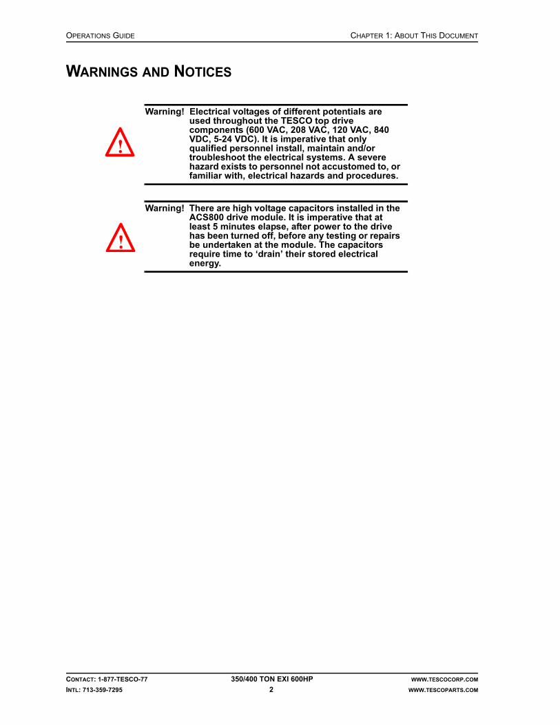
OPERATIONS GUIDE CHAPTER 1: ABOUT THIS DOCUMENT
CONTACT: 1-877-TESCO-77 350/400 TON EXI 600HP WWW.TESCOCORP.COM
INTL: 713-359-7295 2 WWW.TESCOPARTS.COM
WARNINGS AND NOTICES
Warning! Electrical voltages of different potentials are used throughout the TESCO top drive components (600 VAC, 208 VAC, 120 VAC, 840 VDC, 5-24 VDC). It is imperative that only qualified personnel install, maintain and/or troubleshoot the electrical systems. A severe hazard exists to personnel not accustomed to, or familiar with, electrical hazards and procedures.
Warning! There are high voltage capacitors installed in the ACS800 drive module. It is imperative that at least 5 minutes elapse, after power to the drive has been turned off, before any testing or repairs be undertaken at the module. The capacitors require time to ‘drain’ their stored electrical energy.
!
!

CHAPTER 2: DRIVE SYSTEM OPERATIONS GUIDE
CONTACT: 1-877-TESCO-77 350/400 TON EXI 600HP WWW.TESCOCORP.COM
INTL: 713-359-7295 3 WWW.TESCOPARTS.COM
CHAPTER 2: DRIVE SYSTEM
SYSTEM DESCRIPTION
The 350/400 EXI 600 Top Drive features a 600 hp induction motor coupled with an ABBACS800 variable frequency drive. The system voltage is 600 VAC and can be supplied by a self-contained generator or directly from the rig’s AC bus.
The motor is rated for 600hp with 150% overload capability for 60 seconds. The maximumspeed of the motor is 2,340 rpm. The motor can produce a maximum torque of 2,700 ft-lb (3,661 N-m). RTDs are embedded in the motor’s stator windings to monitor the motor temperature during operation.
The ABB ACS800 variable frequency drive (VFD) is a modular unit comprised of four main sections: a main breaker and control cabinet, a diode supply unit, two inverter modules, and a dynamic braking unit. The main breaker is rated for 1,000A and features an undervoltage trip circuit, which is tied directly to the ESD control on the driller’s panel. The dynamic brake is connected to a grid resistor which is mounted on the rear outside wall of the power module.
The 350/400 EXI 600 uses a closed loop speed control scheme with variable torque limits. The top drive motor is driven by the ACS800 variable frequency drive which in turn is controlled by a GE Fanuc PLC via RS485 serial communication. The PLC issues START/STOP com-mands as well as speed reference and torque limit values to the VFD. The VFD then drives the motor accordingly. The PLC receives speed feedback from the motor encoder, as well as torque feedback from the VFD. It also controls the auxiliary robotics functions of the top drive.
DRIVE CONTROL PANEL
The Drive Control Panel CDP312R is a small keypad located on the front door of the main VFD breaker cabinet. It provides a visual user interface for setting and displaying drive parameters, monitoring drive status, and indicating warnings and faults.
Figure 2-1 through Figure 2-7 show the Drive Control Panel and describes the function of indicators and keys.
1. Only qualified TESCO personnel certified by ABB should attempt to change or modify drive parameters. Incorrect drive programming may result in equipment damage or injury to personnel. As a precaution, the drive parameters are password protected to prevent unauthorized access.

OPERATIONS GUIDE CHAPTER 2: DRIVE SYSTEM
CONTACT: 1-877-TESCO-77 350/400 TON EXI 600HP WWW.TESCOCORP.COM
INTL: 713-359-7295 4 WWW.TESCOPARTS.COM
The panel can be operated to perform the following actions:
• display actual motor signals such as speed, torque, frequency, etc.• reset the fault and warning messages• change between local and external drive control
Figure 2-1: ACS800

CHAPTER 2: DRIVE SYSTEM OPERATIONS GUIDE
CONTACT: 1-877-TESCO-77 350/400 TON EXI 600HP WWW.TESCOCORP.COM
INTL: 713-359-7295 5 WWW.TESCOPARTS.COM
Figure 2-2: Panel operation mode keys and displays

OPERATIONS GUIDE CHAPTER 2: DRIVE SYSTEM
CONTACT: 1-877-TESCO-77 350/400 TON EXI 600HP WWW.TESCOCORP.COM
INTL: 713-359-7295 6 WWW.TESCOPARTS.COM
Figure 2-3: Actual signal display mode

CHAPTER 2: DRIVE SYSTEM OPERATIONS GUIDE
CONTACT: 1-877-TESCO-77 350/400 TON EXI 600HP WWW.TESCOCORP.COM
INTL: 713-359-7295 7 WWW.TESCOPARTS.COM
Figure 2-4: Displaying full name of signals and viewing and resetting history

OPERATIONS GUIDE CHAPTER 2: DRIVE SYSTEM
CONTACT: 1-877-TESCO-77 350/400 TON EXI 600HP WWW.TESCOCORP.COM
INTL: 713-359-7295 8 WWW.TESCOPARTS.COM
Figure 2-5: Displaying and resetting an active fault

CHAPTER 2: DRIVE SYSTEM OPERATIONS GUIDE
CONTACT: 1-877-TESCO-77 350/400 TON EXI 600HP WWW.TESCOCORP.COM
INTL: 713-359-7295 9 WWW.TESCOPARTS.COM
MONITORING THE DRIVE
The Drive Control Panel allows the user to display the operational status of the drive. The table below lists and describes the actual signals available for monitoring.
Figure 2-6: Monitoring the drive - table 1

OPERATIONS GUIDE CHAPTER 2: DRIVE SYSTEM
CONTACT: 1-877-TESCO-77 350/400 TON EXI 600HP WWW.TESCOCORP.COM
INTL: 713-359-7295 10 WWW.TESCOPARTS.COM
Figure 2-7: Monitoring the drive - table 2

CHAPTER 3: DRILLER’S PANEL OPERATIONS GUIDE
CONTACT: 1-877-TESCO-77 350/400 TON EXI 600HP WWW.TESCOCORP.COM
INTL: 713-359-7295 11 WWW.TESCOPARTS.COM
CHAPTER 3: DRILLER’S PANEL
GENERAL DESCRIPTION
The driller’s panel is a stainless steel enclosed panel that provides access to all required switches, indicators, mounts, gauges and connectors.
The driller’s panel provides the controls, instrumentation and indicators required for safe operation of the top drive. The panel mounts at the rig floor, within convenient reach of the driller.
The driller’s panel interfaces with the main panel control system.
Table 3-1: Features of the 350/400 TON EXI 600HP driller’s panel
Controls
• robotic functions• drive functions• Emergency Shut Down (E.S.D.)
Meters
• SET speed• DELIVERED speed• SET torque• DELIVERED torque
Indicators
• warnings• status

OPERATIONS GUIDE CHAPTER 3: DRILLER’S PANEL
CONTACT: 1-877-TESCO-77 350/400 TON EXI 600HP WWW.TESCOCORP.COM
INTL: 713-359-7295 12 WWW.TESCOPARTS.COM
Figure 3-1: Driller’s panel

CHAPTER 3: DRILLER’S PANEL OPERATIONS GUIDE
CONTACT: 1-877-TESCO-77 350/400 TON EXI 600HP WWW.TESCOCORP.COM
INTL: 713-359-7295 13 WWW.TESCOPARTS.COM
CONTROLS, INDICATORS, AND WARNING LIGHTS
Warning Lights
Controls and Indicators for Robotic Functions
Unless indicated otherwise, a switch is in the ‘neutral’ position when it is in the central, vertical position.
Indicator Description
SYSTEM TEMP.(red indicator light)
The system temperature light illuminates under normal conditions. It will flash 3 times per second if the temperature of the motor windings exceeds 155ºC (311ºF). The top drive will shut down if the temperature exceeds 175ºC (347ºF).
lube press.(red indicator light)
The lubrication pressure light does not illuminate under normal conditions. If the gearbox lubrication pressure is lost (i.e., there is no lubrication), the light will start to flash for two minutes and then illuminates continuously. The system maintains functionality while the light is flashing. Quill rotation is shut down when the light illuminates continuously.
Control/Indicator Description/Function
AUXILIARY PUMPOFF/ON (switch)
Use this switch to start or stop the auxiliary hydraulic oil pump.
ROBOTICS ‘ON’(green indicator light)
When this light is illuminated, it indicates that a robotics function has been selected.
ELEVATOROPEN/CLOSE(switch; OPEN is spring-return to neutral; CLOSE is maintained)
Use the ELEVATOR OPEN/CLOSE switch in conjunction with the SAFETY OPEN button to operate the elevators.How to open the elevators:1. Turn the switch to the OPEN position and hold it there.2. Press the SAFETY OPEN push button.How to close the elevators:Turn the switch to the ‘CLOSE’ position, or push the ELEV button on the brake handle.
SAFETY OPEN(push button)
Use this push button in conjunction with the ELEVATOR–OPEN switch to open the elevators.
TILTBACK/FWD (switch; position is maintained)
Use this switch to tilt the elevator links backward and forward.
FLOAT(push button)
Press this button to relieve pressure in the TILT cylinders. This will return the elevator links to the neutral position (vertical below the top drive).
EXTENDIN/OUT(switch; spring-return to neutral)
Use this switch to extend the top drive away from the torque track (OUT) or retract the top drive towards the torque track (IN) to its original position.
VALVEOPEN/CLOSE(switch; spring-return to neutral)
Use this switch to operate the actuator for the mudsaver valve. A mechanical link between the actuator and the mudsaver valve opens and closes the valve.

OPERATIONS GUIDE CHAPTER 3: DRILLER’S PANEL
CONTACT: 1-877-TESCO-77 350/400 TON EXI 600HP WWW.TESCOCORP.COM
INTL: 713-359-7295 14 WWW.TESCOPARTS.COM
Drive Controls and Indicators
VALVE ‘CLOSED’(yellow indicator light)
When this light is illuminated, it indicates that ‘VALVE–CLOSE’ has been selected.
GRABBEROPEN/CLOSE (switch; OPEN is spring-return to neutral; CLOSE is maintained)
Use this switch to open and close the grabber. To achieve full clamping pressure, keep the switch in the ‘CLOSE’ position.
GRABBER ‘CLOSED’(yellow indicator light)
When this light is illuminated, it indicates that ‘GRABBER–CLOSE’ has been selected at the driller’s panel.
CDSAPPLY/RELEASE(switch; RELEASE is spring return to neutral; APPLY is maintained)
Use the CDS APPLY/RELEASE switch in conjunction with the SAFETY RELEASE button to operate the Casing Drive System.How to APPLY the CDS:1. Turn the switch to the ‘APPLY’ position.How to RELEASE the CDS:1. Turn the switch to the RELEASE position and hold it there.2. Press the SAFETY RELEASE button.
PIPE HANDLERREV/FWD(switch; spring return to neutral)
Use this switch to rotate the pipe handler in ‘REV/FWD’.Pipe handler must be unlocked.
PIPE HANDLERUNLOCK/LOCK(switch; UNLOCK is spring return to neutral; LOCK is maintained)
Use this switch to LOCK or UNLOCK the pipe handler. When the pipe handler is unlocked, it can be rotated to make pipe handling easier.
PIPE HANDLER ‘CAUTION’(yellow indicator light)
The indicator light illuminates when the pipe handler is ‘UNLOCKED’.
Control/Indicator Description/Function
READY(green indicator light)
When this light is illuminated, it indicates that there are no drive system faults, and the unit is ready for operation.
E.S.D.(Emergency Shut Down push button)
Push this button to trip the main breaker that supplies power to the drive system. This button will also deactivate the auxiliary pump.Rotation stops when this button is pushed, but the drive system might require up to five minutes to dissipate voltage.There is a separate E.S.D. push button on the power module building.
MODULE ‘ON’(green indicator light)
When this light is illuminated, it indicates that the main breaker MB1 (which energizes the drive system) is turned on.
ENABLEOFF/ON (switch)
Turn this switch to ‘ON’ to prepare the drive to accept rotational commands.
RESET(button; spring-return)
Push this button to reset the faults of the drive system.
DRIVE SETOFF/ON (keyed switch; spring-return)
Use this switch to set the speed and torque limits for rotational functions. It works only if the ENABLE switch is set to ‘OFF’. See “Controls for Torque and Speed” on page 19 for more information.
Control/Indicator Description/Function

CHAPTER 3: DRILLER’S PANEL OPERATIONS GUIDE
CONTACT: 1-877-TESCO-77 350/400 TON EXI 600HP WWW.TESCOCORP.COM
INTL: 713-359-7295 15 WWW.TESCOPARTS.COM
Controls for Quill/Rotation Functions
Meters
It is possible to calibrate the torque meters to display DNm, although this is rarely required. For more information, contact a qualified TESCO representative.
ROBOTIC AND E.S.D. FUNCTION DESCRIPTIONS
The following convention is used to describe switch functions: SWITCHNAME–SETTING
Examples:
• ELEVATOR–OPEN• VALVE–CLOSE• GRABBER–OPEN• MODE–DRILL
The auxiliary hydraulic pump must be manually started to operate most robotics functions. The exceptions are the GRABBER and VALVE functions. If selecting either of these functions, the auxiliary hydraulic pump starts automatically.
Control/Indicator Description/Function
QUILLREV/FWD (switch;maintained position)
Use this switch to select the direction of rotation for the top drive quill.
SPEEDDECR/INCR (switch; spring-return)
Use this switch to increase or decrease the quill speed. See “Controls for Torque and Speed” on page 19 for more information.
TORQUEDECR/INCR (switch; spring-return)
Use this switch to increase or decrease the torque output limit of the drive. See “Controls for Torque and Speed” on page 19 for more information.
BREAKOUT(push button; spring-return)
Push this button and hold to apply maximum reverse torque. (Only functional in Connect - REV mode.)
MODECONN/DRILL (switch)
Use this switch to select the CONNECTION mode or the DRILL mode.
Indicator Description
DELIVERED SPEED This meter displays the actual quill speed of the top drive.
SET TORQUE This meter displays the max. torque setting selected by the driller. The value is expressed in ft-lb See “Controls for Torque and Speed” on page 19 for more information.
DELIVERED TORQUE This meter displays the actual torque delivered by the top drive. The value is expressed in ft-lb.

OPERATIONS GUIDE CHAPTER 3: DRILLER’S PANEL
CONTACT: 1-877-TESCO-77 350/400 TON EXI 600HP WWW.TESCOCORP.COM
INTL: 713-359-7295 16 WWW.TESCOPARTS.COM
ELEVATOR Function
The hydraulic elevators attach to the end of the elevator links. They clamp around and manipulate drill pipe, collars, drilling tools and casing.
Safety features for the elevators include a double-action OPEN switch. The 3-position ELEVATOR switch on the driller’s panel works in conjunction with the elevator SAFETY OPEN push button. To open the elevators, turn the ELEVATOR switch to ‘OPEN’ and press the SAFETY OPEN push button at the same time; this prevents accidental opening of the elevators. Operating either switch by itself will not energize the elevator solenoid. Additionally, the switch and the push button are ‘spring-return to neutral’, ensuring that both have to be manually selected each time ELEVATOR-OPEN is required.
Another safety feature for the elevators is ensuring that the elevators fully close and latch. When selecting ‘ELEVATOR–CLOSE’ at the driller’s panel, pressure to the CLOSE circuit remains high for enough time to positively engage the latch.
The driller can also use the CLOSE button on the brake handle to close the elevators. This allows the driller to close the elevators (and lower or raise the drawworks) by using one hand, and leaves the other hand free to operate other drilling controls.
TILT Function
The TILT function allows the operator to move the elevator links (with the attached elevators) to a position forward or back of hole center (the links move up to 55° forward and up to 35° back of hole center). Use the TILT function to manipulate pipe stands when tripping pipe, run-ning casing, and making up pipe stands. Use the TILT function in conjunction with other func-tions to rack back pipe stands, make up pipe stands in the mouse hole, and retrieve pipe stands for reconnection.
Use the TILT–BACK function to move the links and elevators out of the way and lower the top drive closer to the rig floor, or to reposition the links to an angle back of hole center.
Use the TILT–FWD function to move the links and elevators away from hole center and toward the V-door.
The FLOAT function returns the links to hole center. When pushing the FLOAT button on the driller’s panel, this relieves the pressure in the TILT cylinders and the links return to a vertical position below the top drive.
EXTEND Function
Use the EXTEND function to handle stands of drill pipe during tripping, or to handle rig tools when the top drive is not over hole center. The EXTEND function moves the entire top drive away from the torque track to a maximum distance of 60 in (1.5 m).
CHAPTER 3: DRILLER’S PANEL OPERATIONS GUIDE
CONTACT: 1-877-TESCO-77 350/400 TON EXI 600HP WWW.TESCOCORP.COM
INTL: 713-359-7295 17 WWW.TESCOPARTS.COM
The EXTEND switch on the driller’s panel is ‘spring-return to neutral’, which means it must be held in the desired position to activate the function. This allows the operator to stop the top drive at any point along its travel path by releasing the switch. Operators can also ‘jog’ (move in small increments) the top drive along its travel path by momentarily selecting EXTEND–IN or EXTEND–OUT.
Use the EXTEND–OUT function to move the top drive away from the torque track and towards the V-door. This enables the operator to handle stands of drill pipe more effectively when additional distance from hole center is desired. Combine this function with the TILT–FORWARD function to achieve maximum extension of the top drive.
Use EXTEND–IN to move the top drive towards its original position over hole center.
VALVE Function
The VALVE function operates the mud valve actuator, which opens and closes the mudsaver section of the mud valve. The mud valve is a double-ball valve. The lower ball is used for well control and the upper ball is used as a mudsaver.
The mud pump(s) must be deactivated when making or breaking pipe joints. Use the VALVE function to close the mudsaver valve to prevent gravity loss of drilling fluid that is trapped in the swivel, quill and hose.
When selecting VALVE–CLOSE at the driller’s panel, electrical controls stop the quill rotation. The valve closes and an eight-second timer activates. After the timer expires, restart the quill rotation by setting the QUILL switch to neutral, then to ‘FWD’ or ‘REV’.
Note: When the mud pump interlock is properly installed it will prevent the mud pump from starting if the valve is closed.
When selecting ‘VALVE–CLOSE’, a yellow warning light illuminates on the driller’s panel and remains lit until ‘VALVE–OPEN’ is selected.
GRABBER Function
The grabber is a hydraulically operated device used to clamp onto and hold pipe. It is located at the bottom of the grabber leg of the top drive. The grabber is used as break-out tongs for making or breaking pipe stand joints to or from the top drive.
The GRABBER–OPEN switch on the driller’s panel is ‘spring-return to neutral’, and it requires only momentary functioning to begin the OPEN sequence. The GRABBER–CLOSE switch is ‘maintained’, which means that it maintains power to the CLOSE hydraulic direc-tional valves until the operator manually turns the switch to the neutral position.
The yellow GRABBER ‘CLOSED’ warning light on the driller’s panel illuminates when selecting the GRABBER–CLOSE function.
TESCO recommends installing safety interlocks that prevent the operator from hoisting the drawworks when the grabber is closed (unless the operator presses an override button on the brake handle). A separate PLC-programmed interlock prevents the grabber from closing if the quill speed is greater than 5 rpm.

OPERATIONS GUIDE CHAPTER 3: DRILLER’S PANEL
CONTACT: 1-877-TESCO-77 350/400 TON EXI 600HP WWW.TESCOCORP.COM
INTL: 713-359-7295 18 WWW.TESCOPARTS.COM
PIPE HANDLER Function
The pipe handler section of the top drive is located from the slewing bearing down, and is designed to rotate independently of the Swivel gearbox of the top drive. The pipe handler allows the operator to handle pipe stands and downhole tools easily and conveniently.
The pipe handler section is locked to the swivel gearbox of the top drive at the slewing bearing. The PIPE HANDLER switch on the driller’s panel must be set to ‘UNLOCK’ before accessing the ROTATE function. The Pipe Handler is independently driven by a hydraulic motor and does not utilize the electric drive system.
The direction of rotation for the pipe handler is determined by the pipe handler REV/FWD switch. 360° rotation is available. Release the REV/FWD switch to stop rotation. The pipe handler rotates at approximately 4 rpm, but may be adjusted using the flow control valves next to the hydraulic motor. The pipe handler rotates at a fixed speed of approximately 8 rpm.
A yellow CAUTION light illuminates at the driller's panel when the pipe handler is ‘UNLOCKED’.
Emergency Shut Down (E.S.D.)
There are two E.S.D. circuits, each with its own specific function.
E.S.D. on the Driller's Panel
Push the E.S.D. button on the driller's panel to trip the main circuit breaker (the breaker supplies 600 VAC to the ACS800 drive and is located in the power module building). This removes all high voltage power from the drive. The quill stops rotating. This E.S.D. also deactivates the auxiliary hydraulic pump. All devices that operate or rotate at the drill floor become inactive.
When resetting (pulling out) the E.S.D. switch, the auxiliary pump can be activated from the driller’s panel, however, power cannot be activated for the drive system from the driller’s panel. Follow standard start-up procedures to restart the drive.
E.S.D. on the Main Panel Control System
Push the E.S.D. button on the door of the power module main panel to cut all power to the TESCO power module. This E.S.D. switch is interlocked to trip the breaker for the main service power supply.
Reset E.S.D
The E.S.D. button has spring-return. Reset and activate the main breaker to restore power to the power module.

CHAPTER 3: DRILLER’S PANEL OPERATIONS GUIDE
CONTACT: 1-877-TESCO-77 350/400 TON EXI 600HP WWW.TESCOCORP.COM
INTL: 713-359-7295 19 WWW.TESCOPARTS.COM
CONTROLS FOR TORQUE AND SPEED
The torque and quill speed that is available is specific to each top drive activity. They are summarized in the following table.
* Refer to “How to Set or Change Drive Parameters” on page 26.
The operator uses the driller’s panel to access the torque and speed functions, and to set the torque and speed limits.
DRILL Forward
DRILL Forward mode is achieved by turning the MODE switch to DRILL, and the QUILL switch to FWD.
Torque
Controls on the driller’s panel allow the operator to increase or decrease the quill torque to suit various tool joints as required during drilling operations. The operator can select from 0 to 100% of the maximum preset torque limit. Preset the maximum torque limit at the driller’s panel before operating the unit (see “How to Set or Change Drive Parameters” on page 26).
Speed
Controls on the driller’s panel allow the operator to increase or decrease the quill speed as required during drilling operations. The full range of the quill speed is available in DRILL Forward mode. Quill speed ranges from 0 to 220 rpm.
DRILL Reverse
DRILL Reverse mode is achieved by turning the MODE switch to DRILL, and the QUILL switch to REV.
Torque
Controls on the driller’s panel allow the operator to increase or decrease the quill torque as required during reverse drilling operations. The operator can select from 0 to 100% of the maximum preset torque limit. Preset the maximum limit at the driller’s panel before operating the unit (see “How to Set or Change Drive Parameters” on page 26).
Table 3-2: Available torque and quill speed
Mode Available Torque Available Speed
DRILL (FWD) 0 to 100% of the maximum preset value* 0 to maximum rpm
DRILL (REV) 0 to 100% of the maximum preset value* 0 to 30 rpm (11.11:1 gear ratio)
CONNECT (FWD) 0 to 100% of the maximum preset value* 0 to maximum rpm
CONNECT (REV) 0 to 100% of the maximum preset value* 0 to 30 rpm (11.11:1 gear ratio)

OPERATIONS GUIDE CHAPTER 3: DRILLER’S PANEL
CONTACT: 1-877-TESCO-77 350/400 TON EXI 600HP WWW.TESCOCORP.COM
INTL: 713-359-7295 20 WWW.TESCOPARTS.COM
Speed
Only one speed is available during reverse drilling operations. The operator presets the DRILL Reverse speed limit at the driller's panel before operating the unit (see “How to Set or Change Drive Parameters” on page 26). The available settable speed in DRILL Reverse mode is 0 to 30 rpm.
CONNECT Forward
CONNECT Forward mode is achieved by setting the MODE switch to CONN, and the QUILL switch to ‘FWD’.
Torque
Controls on the driller’s panel allow the operator to increase or decrease the quill torque to suit various tool joints as required when making connections. The operator can select from 0 to 100% of the maximum preset torque limit. Preset the maximum connect torque limit at the driller's panel before operating the unit (see “How to Set or Change Drive Parameters” on page 26).
Speed
Only one speed is available in CONNECT Forward mode. The operator presets the CON-NECT Forward speed limit at the driller’s panel before operating the unit (see “How to Set or Change Drive Parameters” on page 26).
CONNECT Reverse
Torque
Only one torque setting is available in CONNECT Reverse mode (unless the operator presses the BREAKOUT button). The operator presets the torque limit at the driller’s panel before operating the unit.
Speed
Only one speed setting is available in CONNECT Reverse mode (unless the operator presses the BREAKOUT button). The operator sets the CONNECT Reverse speed limit at the driller’s panel before operating the unit (see “How to Set or Change Drive Parameters” on page 26).
BREAKOUT Button
Press and hold the BREAKOUT button to apply maximum reverse torque to the pipe joint. The torque increases from preset Connect-Reverse torque to the maximum available torque.

CHAPTER 3: DRILLER’S PANEL OPERATIONS GUIDE
CONTACT: 1-877-TESCO-77 350/400 TON EXI 600HP WWW.TESCOCORP.COM
INTL: 713-359-7295 21 WWW.TESCOPARTS.COM
If the pipe joint breaks before the top drive reaches maximum torque, the top drive rotates at the preset BREAKOUT speed. When releasing the BREAKOUT button, the top drive rotates at the preset CONNECT Reverse speed, if this is selected. The system remains in a ‘ready’ state and no temporary shut down occurs.
Dual Function Remote Brake Handle Control
The push button controls on the brake handle operate the ELEVATOR–CLOSE and the GRABBER–Drawworks Interlock Override as described below.
ELEVATOR–CLOSE
To make tripping operations easier, close the elevators from a switch located on the brake handle. This is a ‘spring-return’ push button that activates a timed sequence (eight seconds) to ensure that the elevators close completely. The eight-second sequence activates even if the button is only briefly selected.
GRABBER–Drawworks Interlock Override
The interlock for the drum brake locks out the drum clutch so the driller cannot hoist while the grabber is engaged. A yellow warning light located above the GRABBER switch on the driller’s panel indicates the status of the grabber. If this light is illuminated, it indicates that GRABBER–CLOSE is selected. Use the push button on the brake handle to override the lockout feature.
Note: Use this override during directional drilling operations if the string needs to be hoisted when the grabber is closed.
The override button operates a temporary contact that either a) controls an air valve that allows air back to the drum clutch or b) triggers a PLC signal that interrupts the drawworks controls. The override works only when the button is pushed and held. When the button is released, air supply to the clutch control or the PLC interlock with the drawworks control is once again interrupted and the override is no longer active.
HOW TO CALIBRATE THE METERS ON THE DRILLER’S PANEL
The driller’s panel contains four display meters:
• SET SPEED (rpm)• DELIVERED SPEED (rpm)• SET TORQUE (ft-lb)• DELIVERED TORQUE (ft-lb)
Use the following procedure to calibrate all meters before EVERY job. Recommended settings appear in the tables that follow the procedure.
Although the values are different for each type of meter, calibrate all meters using the same procedure.

OPERATIONS GUIDE CHAPTER 3: DRILLER’S PANEL
CONTACT: 1-877-TESCO-77 350/400 TON EXI 600HP WWW.TESCOCORP.COM
INTL: 713-359-7295 22 WWW.TESCOPARTS.COM
Setting the Decimal Point of the LMD-120A Meters
1. If necessary, stop quill rotation at the top drive.
2. Open the driller’s panel and access the meter.
3. The calibration controls are at the rear of the meter. To access them, remove the rear plug.
4. For the SET SPEED and DELIVERED SPEED meters:
This will display the rpm as a whole number without any decimal places.
5. For the SET TORQUE and DELIVERED TORQUE meters:
This will display the torque values in thousands of foot-pounds. For example, a reading of 20.3 means 20,300 ft-lb.
6. Replace the plug.
7. Calibrate the zero and maximum values according to “Set Driller’s Panel Meters” on page 23.
Figure 3-2: LMD-120A gauge rear view
Switch Setting
1 0
2 0
3 0
4 0
Switch Setting
1 0
2 0
3 1
4 0
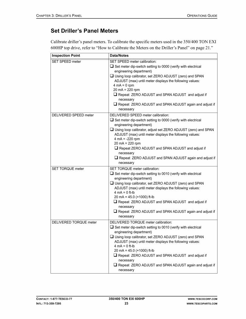
CHAPTER 3: DRILLER’S PANEL OPERATIONS GUIDE
CONTACT: 1-877-TESCO-77 350/400 TON EXI 600HP WWW.TESCOCORP.COM
INTL: 713-359-7295 23 WWW.TESCOPARTS.COM
Set Driller’s Panel Meters
Calibrate driller’s panel meters. To calibrate the specific meters used in the 350/400 TON EXI 600HP top drive, refer to “How to Calibrate the Meters on the Driller’s Panel” on page 21.”
Inspection Point Data/Notes
SET SPEED meter SET SPEED meter calibration: Set meter dip-switch setting to 0000 (verify with electrical engineering department) Using loop calibrator, set ZERO ADJUST (zero) and SPAN ADJUST (max) until meter displays the following values:
4 mA = 0 rpm20 mA = 220 rpm
Repeat ZERO ADJUST and SPAN ADJUST and adjust if necessary
Repeat ZERO ADJUST and SPAN ADJUST again and adjust if necessary
DELIVERED SPEED meter DELIVERED SPEED meter calibration: Set meter dip-switch setting to 0000 (verify with electrical engineering department) Using loop calibrator, adjust set ZERO ADJUST (zero) and SPAN ADJUST (max) until meter displays the following values:4 mA = -220 rpm20 mA = 220 rpm Repeat ZERO ADJUST and SPAN ADJUST and adjust if
necessary Repeat ZERO ADJUST and SPAN ADJUST again and adjust if
necessary
SET TORQUE meter SET TORQUE meter calibration: Set meter dip-switch setting to 0010 (verify with electrical engineering department) Using loop calibrator, set ZERO ADJUST (zero) and SPAN ADJUST (max) until meter displays the following values:4 mA = 0 ft-lb20 mA = 45.0 (×1000) ft-lb
Repeat ZERO ADJUST and SPAN ADJUST and adjust if necessary
Repeat ZERO ADJUST and SPAN ADJUST again and adjust if necessary
DELIVERED TORQUE meter DELIVERED TORQUE meter calibration: Set meter dip-switch setting to 0010 (verify with electrical engineering department) Using loop calibrator, set ZERO ADJUST (zero) and SPAN ADJUST (max) until meter displays the following values:4 mA = 0 ft-lb20 mA = 45.0 (×1000) ft-lb
Repeat ZERO ADJUST and SPAN ADJUST and adjust if necessary
Repeat ZERO ADJUST and SPAN ADJUST again and adjust if necessary

OPERATIONS GUIDE CHAPTER 3: DRILLER’S PANEL
CONTACT: 1-877-TESCO-77 350/400 TON EXI 600HP WWW.TESCOCORP.COM
INTL: 713-359-7295 24 WWW.TESCOPARTS.COM
This page has been left blank intentionally.

CHAPTER 4: TORQUE AND SPEED LIMITS OPERATIONS GUIDE
CONTACT: 1-877-TESCO-77 350/400 TON EXI 600HP WWW.TESCOCORP.COM
INTL: 713-359-7295 25 WWW.TESCOPARTS.COM
CHAPTER 4: TORQUE AND SPEED LIMITS
OVERVIEW
The torque that the top drive can develop is related to the rotational speed of the quill. The relationship between quill rotational speed and maximum drilling torque is nonlinear, as seen in Figure 4-1.
Figure 4-1: EXI 600 Torque Curve

OPERATIONS GUIDE CHAPTER 4: TORQUE AND SPEED LIMITS
CONTACT: 1-877-TESCO-77 350/400 TON EXI 600HP WWW.TESCOCORP.COM
INTL: 713-359-7295 26 WWW.TESCOPARTS.COM
The top drive can produce a maximum continuous drilling torque of 30,000 ft-lb (40,680 N-m) at speeds up to 90 rpm. From 90 rpm up to the maximum speed of 220 rpm, the maximum drilling torque decreases from 30,000 to 12,000 ft-lb (40,680 to 16,272 N-m).
The torque value of 39,000 ft-lb (52,884 N-m) corresponds to the top drive’s maximum makeup torque. This is the torque necessary to connect (‘make’) drill pipe connections at low speed (0 to 30 rpm).
The torque value of 45,000 ft-lb (61,020 N-m) corresponds to the top drive’s breakout torque. This is the torque necessary to disconnect (‘break’) drill pipe connections at very low speed (0 to 8 rpm).
DRIVE PARAMETERS
Overview
The following drive parameters (torque and speed settings) can be set and changed at the driller’s panel:
• DRILL Forward - Torque• DRILL Reverse - Torque and Speed• CONNECT Forward - Torque and Speed• CONNECT Reverse - Torque and Speed• BREAKOUT - Speed
Set the drive parameters for torque and speed to minimize the possibility of injury to personnel and damage to drilling equipment.
For example, limit the torque setting for the DRILL Forward function to help prevent the drill string from twisting off during drilling operations. Limit the speed and torque settings for the CONNECT function to promote the proper make up of tool joints and guard against damage to threads and seal faces caused by over-torquing.
The drive system will not surpass the programmed torque and speed settings, however, the following procedure can be used to change the settings if required.
Use the same steps to set or change a setting for all functions.
How to Set or Change Drive Parameters
This procedure can be performed only if the drive system is disabled.
Danger! Release all torque in the drill before disabling the drive system or damage to the electrical components might occur.
1. At the driller's panel, turn the ENABLE switch to ‘OFF’.
2. Insert the key into the DRIVE SET keyed switch.
3. Turn and hold the key in the ‘SET’ position.
!

CHAPTER 4: TORQUE AND SPEED LIMITS OPERATIONS GUIDE
CONTACT: 1-877-TESCO-77 350/400 TON EXI 600HP WWW.TESCOCORP.COM
INTL: 713-359-7295 27 WWW.TESCOPARTS.COM
4. Use the procedures in the following table to set the required parameter(s):
5. Release the DRIVE SET keyed switch.
6. Remove the key.
7. Push and hold the RESET button for 5 seconds.
8. Set the ENABLE switch to ‘ON’.
Table 4-1: How to set or change drive parameters
To set this parameter Perform these steps
DRILL ForwardTorque
1. Set the MODE switch to DRILL. 2. Set the QUILL switch to FWD.3. Use the TORQUE switch to increase or decrease the SET TORQUE value on
the digital gauge on the driller's panel.Note: Set this limit at 2,000 ft-lb (2,712 N-m) less than the lowest connected joint torque setting (see CONNECT Forward Torque). Consult the Rig Manager or Oil Company Representative to determine the proper setting.Important: If using a downhole mud motor, the torque set limit must be higher than the maximum output of the mud motor.
DRILL ReverseSpeed and Torque
1. Set the MODE switch to DRILL2. Set the QUILL switch to REV.3. Use the SPEED switch to increase or decrease the SET SPEED value on the
digital gauge on the driller's panel.Note: TESCO recommends 10 rpm or less.
4. Use the TORQUE switch to increase or decrease the SET TORQUE value on the digital gauge on the driller's panel.Note: TESCO recommends 10,000 ft-lb (13,560 N-m) or less, depending on the drill string configuration.
CONNECT ForwardSpeed and Torque
1. Set the MODE switch to CONN.2. Set the QUILL switch to FWD.3. Use the SPEED switch to increase or decrease the SET SPEED value on the
digital gauge on the driller's panel.Note: TESCO recommends 15 rpm or less.
4. Use the TORQUE switch to increase or decrease the SET TORQUE value on the digital gauge on the driller's panel.Note: Use the torque requirements for the drill string connections to determine this setting.
CONNECT ReverseSpeed and Torque
1. Set the MODE switch to CONN.2. Set the QUILL switch to REV.3. Use the SPEED switch to increase or decrease the SET SPEED value on the
digital gauge on the driller's panel.Note: TESCO recommends 15 rpm or less.
4. Use the TORQUE switch to increase or decrease the SET TORQUE value on the digital gauge on the driller's panel.Note: TESCO recommends 8,000 ft-lb (10,848 N-m) or less.
BREAKOUT Speed Breakout speed is set to 7 rpm by PLC Logic and is not adjustable.

OPERATIONS GUIDE CHAPTER 4: TORQUE AND SPEED LIMITS
CONTACT: 1-877-TESCO-77 350/400 TON EXI 600HP WWW.TESCOCORP.COM
INTL: 713-359-7295 28 WWW.TESCOPARTS.COM
SETTING TORQUE LIMITS
In order not to exceed the torque limits of the pipe and threaded connections being used, the operator presets torque limits before operations begin. Failure to limit torque may result in damaged pipe and/or connections. Once set, these limits will not be exceeded by the top drive during operations.
The 350/400 EXI 600 top drive can produce 30,000 ft-lb (40,680 N-m) of nominal torque continuously, with 1.5 times overload capability. Therefore the torque lim-its should be set based on the ability of the motor and the drill pipe being used.
In Breakout, the torque will ramp up to maximum 45,000 ft-lb (61,020 N-m). This is the limit for breakout and is not adjustable.
If Connect-Forward/Reverse is selected, the drive will apply torque to the preset value for Connect-Forward/Reverse. For safety, the torque limit for Connect-Reverse is normally set very low to prevent accidental back-off.
Drill-Forward torque limit should be preset to remain within the limitations of the drill pipe being used. During operations, the full range of torque (from zero to the preset limit) is available to the operator. For safety, Drill-Reverse torque is nor-mally set very low, to prevent accidental back-off. If required, higher values can be preset. During operations, the full range of torque (from zero to the preset limit) is available to the operator. This feature allows fully-controlled back-off, if required.
Note: When operating at a speed higher than 90 rpm, the top drive will pro-duce less torque than nominal value.
Breakout
There is no need to set a torque limit for Breakout as the torque applied by the drive system is preprogrammed and unadjustable.
The breakout torque is pre-programmed to 45,000 ft-lb (61,020 N-m) which is the full overload capacity of the motor.
The Set Torque meter is the third one down on the set of four digital meter displays on the right side of the Driller’s Control Panel.
Note: For convenience, speed and torque limit settings can be done in sequence; that is, the operator can set the speed and then set the torque before proceeding to the next rotational function.

CHAPTER 4: TORQUE AND SPEED LIMITS OPERATIONS GUIDE
CONTACT: 1-877-TESCO-77 350/400 TON EXI 600HP WWW.TESCOCORP.COM
INTL: 713-359-7295 29 WWW.TESCOPARTS.COM
Connect Forward
It is recommended that the Connect-Forward torque limit be set to comply with the drill pipe connection specifications. Maximum achievable value is 39,000 ft-lb (52 884 N-m).
1. Ensure that the top drive quill is not rotating.
2. Function ENABLE switch to ‘OFF’.
3. Insert key into DRIVE SET switch, turn clockwise and ‘HOLD’.
4. Select CONN/DRILL switch to ‘CONN’.
5. Select QUILL FORWARD/REVERSE switch to ‘FORWARD’.
6. View SET TORQUE meter and adjust displayed value to desired value using the TORQUE INCREASE/DECREASE switch.
7. Release DRIVE SET switch.
The Connect Forward torque limit is now set.
Connect Reverse
It is recommended that the Connect Reverse torque limit be set at approximately 5,000 to 8,000 ft-lb (6 780 to 10 848 N-m).
1. Ensure that the top drive quill is not rotating.
2. Function ENABLE switch to ‘OFF’.
3. Insert key into DRIVE SET switch and turn clockwise and ‘HOLD’.
4. Select CONN/DRILL switch to ‘CONN’.
5. Select QUILL FORWARD/REVERSE switch to ‘REVERSE’.
6. View SET TORQUE meter and adjust displayed value to desired value using the TORQUE INCREASE/DECREASE switch.
7. Release DRIVE SET switch.
The Connect Reverse torque limit is now set.

OPERATIONS GUIDE CHAPTER 4: TORQUE AND SPEED LIMITS
CONTACT: 1-877-TESCO-77 350/400 TON EXI 600HP WWW.TESCOCORP.COM
INTL: 713-359-7295 30 WWW.TESCOPARTS.COM
Drill Forward
The unit has the capacity to Drill in Forward at a maximum quill speed of 220 rpm.
1. Ensure that the top drive quill is not rotating.
2. Function ENABLE switch to ‘OFF’.
3. Insert key into DRIVE SET switch and turn clockwise and ‘HOLD’.
4. Select CONN/DRILL switch to ‘DRILL’.
5. Select QUILL FORWARD/REVERSE switch to ‘FORWARD’.
6. View SET TORQUE (top) meter and adjust displayed value to desired value using the speed INCREASE/DECREASE switch.
7. Release DRIVE SET switch.
The Drill Forward torque limit is now set.
Drill Reverse
It is recommended that the Drill Reverse torque limit be set at approximately 5,000 to 8,000 ft-lb (6 780 to 10 848 N-m).
1. Ensure that the top drive quill is not rotating.
2. Function ENABLE switch to ‘OFF.’
3. Insert key into DRIVE SET switch, turn clockwise and ‘HOLD’.
4. Select CONN/DRILL switch to ‘DRILL’.
5. Select QUILL FORWARD/REVERSE switch to ‘REVERSE’.
6. View SET TORQUE meter and adjust displayed value to desired value using the TORQUE INCREASE/DECREASE switch.
7. Release DRIVE SET switch.
The Drill Reverse torque limit is now set.
PIPE HANDLER SETTINGS
Pipe Handler Speed
Warning! No person should be within the radius of link movement whenever the Pipe Handler Forward/Reverse switch is operated.
The pipe handler rotates approximately 4 rpm, but the operator may select any speed from 0 to 8 rpm. To modify speed, adjust the needle valves connected to the hydraulic oil supply and return lines of the rotate motor.
!

CHAPTER 5: OTHER PRE-OPERATIONAL PROCEDURES OPERATIONS GUIDE
CONTACT: 1-877-TESCO-77 350/400 TON EXI 600HP WWW.TESCOCORP.COM
INTL: 713-359-7295 31 WWW.TESCOPARTS.COM
CHAPTER 5: OTHER PRE-OPERATIONAL PROCEDURES
INSTALL THE SAVER SUB AND DIE LOCK CLAMP
1. Ensure the PIPE HANDLER switch is set to ‘LOCKED’.
2. Position the saver sub through the grabber box.Note: Ensure the upper pin protrudes above the grabber box.
3. Apply pipe dope to the threads of the saver sub.
4. Attach the saver sub by hand. Note: Tighten as much as possible.
5. Set the GRABBER switch to ‘CLOSE’.
6. Use the TORQUE switch to reduce the torque to approximately 30% of the required make up torque.
7. Set the MODE switch to ‘CONN’.
8. Set the QUILL switch to ‘FWD’.
9. Continue rotation until the connection is fully engaged.
10. Use the TORQUE switch to increase the torque to the torque required to make up the connection.
11. When desired torque is achieved, set the QUILL switch to neutral.
12. Set the GRABBER switch to ‘OPEN’.
13. Place the die lock clamp on top of the grabber box.
14. Loosely install the die lock bolts (8).
15. Raise the die lock clamp into position and hold, either manually or by using the GRABBER LIFT function
Note: Position the clamp so it evenly straddles the connection between the saver sub and the mud valve.
16. Apply anti-seize compound to all cap screws and tighten them all evenly.Note: Monitor the end gaps to ensure that the clamp is installed evenly.
17. Torque all 7/8 in. Grade 8 fasteners to 550 ft-lb (745 N-m).Note: For more information, refer to the appendix titled ‘Torque Specifica-tions for High Strength Fasteners’ in the Maintenance Guide for the unit.
18. Seat the dies.Note: To seat the dies, strike the back side of each half of the clamp as hard as possible with a sledge hammer.
19. When the dies seat properly, torque all bolts to 550 ft-lb (746 N-m).

OPERATIONS GUIDE CHAPTER 5: OTHER PRE-OPERATIONAL PROCEDURES
CONTACT: 1-877-TESCO-77 350/400 TON EXI 600HP WWW.TESCOCORP.COM
INTL: 713-359-7295 32 WWW.TESCOPARTS.COM
ORIENTING THE PIPE HANDLER
Take these precautions before operating the pipe handler:
• Ensure that the links and elevators are hanging vertically.• Ensure that the pipe handler is holding no reactive torque from the drill string. This
can be done by setting the GRABBER switch to ‘OPEN’.
1. Ensure the GRABBER OPEN/CLOSE switch is set to ‘OPEN’.
2. Using the PIPE HANDLER UNLOCK/LOCK switch, select ‘UNLOCK’.Note: The PIPE HANDLER CAUTION light will illuminate.
3. Select ‘PIPE HANDLER FWD/REV’ (depending on desired rotation).
4. When the desired position is reached, release the PIPE HANDLER FWD/REV switch to neutral.
5. Using the PIPE HANDLER UNLOCK/LOCK switch, select ‘LOCK’.
6. If the PIPE HANDLER CAUTION light remains illuminated, the lock has not engaged. Using the REV/FWD switch, rotate the pipe handler slightly until the CAUTION light turns off. This indicates the pipe handler is locked.
SETTING THE GRABBER HEIGHT
The grabber must close on the box connection of the drill string, just below the saver sub. The grabber height can be adjusted from the driller’s panel. To adjust the height, use the following procedure:
1. Determine if the grabber needs to move up or down to align with the connection of the drill string.
2. On the driller’s panel, select ‘OPEN’ on the GRABBER switch.Note: The auxiliary hydraulic pump will start automatically if it is not run-ning at this time.
3. On the driller’s panel, select ‘UP’ or ‘DOWN’ on the GRABBER LIFT switch and hold it there.
4. Release the GRABBER LIFT switch as soon as the grabber reaches the correct height.
5. The grabber height is now set.
CHAPTER 5: OTHER PRE-OPERATIONAL PROCEDURES OPERATIONS GUIDE
CONTACT: 1-877-TESCO-77 350/400 TON EXI 600HP WWW.TESCOCORP.COM
INTL: 713-359-7295 33 WWW.TESCOPARTS.COM
HOW TO ADJUST THE GRABBER-LIFT HEIGHT LIMIT
The grabber-lift height limit is the maximum height to which the grabber can be lifted from the driller’s panel. It is a safety feature incorporated in the grabber-lift circuit to ensure that the grabber is not accidentally lifted too high so it touches the connection lock above the saver sub and causes damage to the top drive.
The height limit can be adjusted to compensate for different heights of the connection clamp. It cannot be adjusted from the driller’s panel, however, it can be manually adjusted at the grabber lift manifold. The height limit adjustment is achieved by increasing or decreasing the stroke of the grabber lift cylinder. The means that by adjusting the grabber-lift height limit, the lower limit to which the grabber can be lowered to, is adjusted as well. This is usually not a problem as typically there is no equipment below the grabber that can cause interference when the grabber is lowered.
Follow the procedure below to decrease the grabber-lift height limit:
1. At the driller’s panel, set QUILL to neutral. Confirm there is no quill rotation.
2. At the rotary seal (see Figure 5-1 on page 34), open the needle valve.
3. Check to see if the grabber is opened. If not, at the driller’s panel select ‘OPEN’ on the GRABBER switch and ensure the grabber is fully opened.
4. At the driller’s panel, select and hold ‘DOWN’ on the GRABBER LIFT switch until the grabber stops lowering.
5. Release the GRABBER LIFT switch and allow it to return to neutral.
6. Close the needle valve.
7. Select and hold ‘UP’ on the GRABBER LIFT switch until it stops.
8. While still holding the GRABBER LIFT switch to ‘UP’, slowly open the needle valve (see Figure 5-1 on page 34). Watch while the grabber rises slowly.
Caution: Pinching hazard. Stay clear of the grabber while it is lifting.
9. Once the grabber reaches the desired height, close the needle valve.
10. Release the GRABBER LIFT switch and allow it to return to neutral.
11. Select ‘DOWN’ on the GRABBER LIFT switch and allow the grabber to lower about 6”.
12. Select ‘UP’ on the GRABBER LIFT switch and allow the grabber to rise until it stops. Release the GRABBER LIFT switch.
Confirm that the grabber has stopped at the desired grabber-lift height limit. The adjustment procedure is now complete.

OPERATIONS GUIDE CHAPTER 5: OTHER PRE-OPERATIONAL PROCEDURES
CONTACT: 1-877-TESCO-77 350/400 TON EXI 600HP WWW.TESCOCORP.COM
INTL: 713-359-7295 34 WWW.TESCOPARTS.COM
Follow the procedure below to increase the grabber-lift height limit:
1. At the driller’s panel, set QUILL to neutral. Confirm there is no quill rotation.
2. At the driller’s panel, select OPEN on the GRABBER switch.
3. At the driller’s panel, select and hold UP on the GRABBER LIFT switch until the grabber stops at the current height limit.
4. While still holding the GRABBER LIFT switch to UP, slowly open the needle valve, see Figure 4-1). Watch while the grabber rises slowly.
Caution: Pinching hazard. Stay clear of the grabber while it is lifting.
5. Once the grabber reaches the desired height, close the needle valve.
6. Release the GRABBER LIFT switch and allow it to return to neutral.
7. Select DOWN on the GRABBER LIFT switch and allow the grabber to lower about 6”.
8. Select UP on the GRABBER LIFT switch and allow the grabber to rise until it stops. Release the GRABBER LIFT switch.
9. Confirm that the grabber has stopped at the desired grabber-lift height limit. The adjustment procedure is now complete.
Figure 5-1: Rotary seal valve

CHAPTER 5: OTHER PRE-OPERATIONAL PROCEDURES OPERATIONS GUIDE
CONTACT: 1-877-TESCO-77 350/400 TON EXI 600HP WWW.TESCOCORP.COM
INTL: 713-359-7295 35 WWW.TESCOPARTS.COM
SETTING THE GRABBER CLOSING PRESSURE
The grabber hydraulic circuit incorporates a hydraulic oil pressure boosting device (intensifier), which allows the grabber to operate at much higher hydraulic pressure than the rest of the auxiliary hydraulic system. This results in much higher grabber clamping forces, very useful when using larger drill pipe sizes.
In some cases, when drilling with small pipe sizes, it may be necessary to reduce the grabber clamping force to avoid damaging the tool joints. This can be achieved by reducing the grabber closing hydraulic oil pressure. Follow the procedure below to adjust the grabber closing pressure:
1. Set the grabber switch to ‘OPEN’.
2. Using the GRABBER LIFT needle valves, position the grabber to close around the saver sub, or other suitable tubular which can withstand high clamping force.
3. Using the GRABBER OPEN/CLOSE switch, select ‘CLOSE’.
4. Read the grabber high pressure oil gauge located on the grabber intensifier mani-fold. The highest possible pressure is approximately 5,000 psi (34.4 MPa).
5. Adjust the pressure reducing valve using an allen key.Note: Clockwise rotation = increase; counter-clockwise rotation = decrease.
6. Monitor gauge pressure until the pressure reading is a the appropriate level, as described in Table 5-1 for corresponding drill pipe size.
7. Using the GRABBER OPEN/CLOSE switch, select ‘OPEN’, then ‘CLOSE’, and confirm gauge pressure. Re-adjust if necessary.

OPERATIONS GUIDE CHAPTER 5: OTHER PRE-OPERATIONAL PROCEDURES
CONTACT: 1-877-TESCO-77 350/400 TON EXI 600HP WWW.TESCOCORP.COM
INTL: 713-359-7295 36 WWW.TESCOPARTS.COM
Note: The oil pressure intensifier counterbalance valve is factory preset and should not be adjusted.
Figure 5-2: Grabber intensifier manifold
Table 5-1: Correct pressure for different drill pipe sizes
Drill Pipe Size Type of Connection Grabber Closing Pressure (psi)
3 1/2” NC38 (3 1/2 IF) 2,500 to 3,000
3 1/2” NC40 (4 FH) 3,000 to 3,500
4” NC40 (4 FH) 3,000 to 3,500
4” NC46 (4 IF) 3,500 to 4,000
4 1/2” NC46 (4 IF) & NC50 (4 1/4 IF) 4,000 to 4,500
5” and larger NC50 (4 1/2 IF) or larger 4,500 to 5,000 max

CHAPTER 6: MAKING/BREAKING CONNECTIONS OPERATIONS GUIDE
CONTACT: 1-877-TESCO-77 350/400 TON EXI 600HP WWW.TESCOCORP.COM
INTL: 713-359-7295 37 WWW.TESCOPARTS.COM
CHAPTER 6: MAKING/BREAKING CONNECTIONS
WARNINGS
Mudsaver Valve
When operating the mudsaver valve, the valve switch applies pressure to the actuator. If the quill rotates with pressure applied, seal damage can result. Because of this, a mudsaver inter-lock stops the quill rotation for five seconds while the valve operates.
If operating the mudsaver VALVE switch while the quill is rotating, an interlock in the PLC program prevents damage to the actuator seals as follows:
• The PLC program stops quill rotation. • The PLC allows the mudsaver valve to complete its timed circuit.
When the circuit is complete, the top drive will restart automatically.
Pipe Slips
Danger! Always use caution when setting and removing pipe slips. If setting the slips when the rotary table is locked, this might trap torque in the drill string. When removing the slips, any trapped torque might release and turn the drill string. Hoist the drill string free of the slips before removing the slips.
!
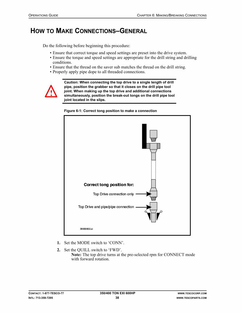
OPERATIONS GUIDE CHAPTER 6: MAKING/BREAKING CONNECTIONS
CONTACT: 1-877-TESCO-77 350/400 TON EXI 600HP WWW.TESCOCORP.COM
INTL: 713-359-7295 38 WWW.TESCOPARTS.COM
HOW TO MAKE CONNECTIONS–GENERAL
Do the following before beginning this procedure:
• Ensure that correct torque and speed settings are preset into the drive system.• Ensure the torque and speed settings are appropriate for the drill string and drilling
conditions.• Ensure that the thread on the saver sub matches the thread on the drill string.• Properly apply pipe dope to all threaded connections.
Caution: When connecting the top drive to a single length of drill pipe, position the grabber so that it closes on the drill pipe tool joint. When making up the top drive and additional connections simultaneously, position the break-out tongs on the drill pipe tool joint located in the slips.
1. Set the MODE switch to ‘CONN’.
2. Set the QUILL switch to ‘FWD’.Note: The top drive turns at the pre-selected rpm for CONNECT mode with forward rotation.
Figure 6-1: Correct tong position to make a connection
!

CHAPTER 6: MAKING/BREAKING CONNECTIONS OPERATIONS GUIDE
CONTACT: 1-877-TESCO-77 350/400 TON EXI 600HP WWW.TESCOCORP.COM
INTL: 713-359-7295 39 WWW.TESCOPARTS.COM
3. Apply back-up tong to tool joint in the slips.Note: If making up the top drive and lower connection at the same time, apply the back-out tong below the lower connection. If making up a top drive connection only, apply the break-out tong to the single length of pipe. In this case, use the grabber instead of a break-out tong.
4. Slowly lower the top drive to the connection.
5. Ensure that the box connection enters into the drill pipe guide.
6. Monitor the weight indicator gauge.
7. Continue to lower the top drive until the weight indicator begins to fluctuate.
Caution: Ensure that the Vernier dampening valve (located on the weight indicator) is open.
8. Lead the top drive into the connection.Note: Lower the top drive in small increments as the connection rotates in. Keep a small amount of weight on the connection (i.e. the weight indi-cator should register only a small amount of weight). This prevents the top drive from “lifting” the stand or single section of drill pipe and damaging the threaded connections.
9. Continue forward rotation until the connection is fully engaged.Note: The top drive stalls when it reaches the preset SET torque. The for-ward rotation speed then drops to zero.
10. Use the TORQUE switch to increase the torque setting to the torque required for the current connection and thread type.
11. Monitor the DELIVERED TORQUE gauge.
12. When the DELIVERED TORQUE gauge displays the desired make up torque value, set the QUILL switch to NEUTRAL.
13. Wait until the DELIVERED TORQUE gauge value decreases to zero.
14. Remove the back-up tong, or open the grabber (if used).
How to Use the Mousehole to Connect Drill Pipe to the Top Drive
Pipe Handler Orientation–Grabber to V-door
Use this procedure when drilling with single lengths of pipe.
Note: This procedure applies when making connections when the mousehole is not off-set.
Caution: Ensure that the tilt links are close to hole center when hoisting pipe out of the mousehole with the pipe handler in this orientation. This will prevent the links from hitting the torque track.
1. Put a single length of pipe in the mousehole.
2. Apply pipe dope to the box connection on the drill pipe.
3. Set the EXTEND switch to ‘OUT’.
4. Extend the top drive until it is situated directly over the mousehole.
!
!

OPERATIONS GUIDE CHAPTER 6: MAKING/BREAKING CONNECTIONS
CONTACT: 1-877-TESCO-77 350/400 TON EXI 600HP WWW.TESCOCORP.COM
INTL: 713-359-7295 40 WWW.TESCOPARTS.COM
5. Lower the top drive until the elevator and elevator links are near the rig floor.
6. Using the TILT FWD/BACK switch, select ‘BACK’.
7. Move the elevator links and elevators backward and out of the way of the connec-tion.
8. Lower the top drive until the saver sub is within a foot of the pipe connection.
9. Using the MODE switch, select ‘CONN’.
10. Using the QUILL switch, select ‘FWD’.
11. Using the TORQUE switch, set torque to 30% of required torque.Note: Ensure the top drive and the single length of pipe are aligned to avoid cross-threading.
12. Slowly lower the top drive to engage the connection between the saver sub and the drill pipe.
13. Lead the top drive into the connection.Note: If the pipe starts to spin in the mousehole, set the QUILL switch to neutral. Close the grabber on the tool joint of the drill pipe, then set the QUILL switch to ‘FWD’.
14. When the connection is fully engaged (shoulders up), set the QUILL switch to neutral.
15. Complete the connection as described in one of the following procedures:• “How to Fully Torque a Connection” on page 42.• “How to Connect a Single Length of Drill Pipe to the Drill String” on page 42.
Figure 6-2: Correct position for elevator links and elevator

CHAPTER 6: MAKING/BREAKING CONNECTIONS OPERATIONS GUIDE
CONTACT: 1-877-TESCO-77 350/400 TON EXI 600HP WWW.TESCOCORP.COM
INTL: 713-359-7295 41 WWW.TESCOPARTS.COM
Pipe Handler Orientation–Grabber to Drawworks
Use this procedure when connecting the occasional individual single length of pipe from the mousehole to the drill string.
Caution: Ensure that the tilt links are close to the drill pipe when hoisting pipe out of the mousehole with the pipe handler in this orientation. This will prevent the racking platform from being hit.
1. Ensure a single length of pipe is located in the mousehole.
2. Properly dope the drill pipe box connection.
3. Using the EXTEND switch, select ‘OUT’.
4. Extend the top drive until it is situated directly over the mousehole.
5. Lower the top drive until it is near the rig floor.
6. Set the TILT switch to ‘BACK’.
7. Move the links and elevators backward and out of the way of the connection.
8. Lower the top drive until the saver sub is within 1 ft of the pipe connection.
9. Set the MODE switch to ‘CONN’.
10. Set the QUILL switch to ‘FWD’.
Figure 6-3: Elevator links and elevator position with grabber to drawworks
!

OPERATIONS GUIDE CHAPTER 6: MAKING/BREAKING CONNECTIONS
CONTACT: 1-877-TESCO-77 350/400 TON EXI 600HP WWW.TESCOCORP.COM
INTL: 713-359-7295 42 WWW.TESCOPARTS.COM
11. Use the TORQUE switch to decrease the torque value to 30% of preset torque value.
Note: Properly align the top drive and drill pipe to avoid cross-threading.
12. Slowly lower the top drive to engage the connection between the saver sub and the drill pipe.
13. Lead the top drive into the connection.Note: If the pipe starts to spin in the mousehole, set the QUILL switch to NEUTRAL. Close the grabber on the drill pipe tool joint, then set the QUILL switch to ‘FWD’.
14. When the connection is fully engaged, set the QUILL switch to neutral (and open the grabber if necessary).
15. Complete the connection using one of the following procedures:• “How to Fully Torque a Connection” on page 42.• “How to Connect a Single Length of Drill Pipe to the Drill String” on page 42.
How to Fully Torque a Connection
1. Ensure the pipe handler is ‘LOCKED’.
2. Set the GRABBER switch to ‘CLOSE’.
3. Set the MODE switch to ‘CONN’.
4. Set the QUILL switch to ‘FWD’.
5. Use the TORQUE switch to increase the SET TORQUE to make up torque value required for the current connection and thread type.
6. When the torque value matches the value required to fully torque the connection to specification, set the QUILL switch to neutral.
7. Set the GRABBER switch to ‘OPEN’.
How to Connect a Single Length of Drill Pipe to the Drill String
1. Hoist the single length of pipe out of the mousehole without torquing the connection.
2. Set the EXTEND switch to ‘IN’.
3. Retract the extend arms until the top drive is positioned over hole center.
4. Place break-out tongs on the tool joint of the drill pipe that is held by the rig slips.
5. Apply pipe dope to the tool joint box.
6. Lower the top drive to stab the drill pipe into the tool joint box of the drill pipe held in the rig slips.
7. Use the TORQUE switch to decrease the torque setting to 40-50% of the present value.
8. Set the MODE switch to ‘CONN’.
9. Set the QUILL switch to ‘FWD’.
10. Lead the top drive into the connection.
11. When the connection fully engages, use the TORQUE switch to set the make up torque required for the current connection and thread type.

CHAPTER 6: MAKING/BREAKING CONNECTIONS OPERATIONS GUIDE
CONTACT: 1-877-TESCO-77 350/400 TON EXI 600HP WWW.TESCOCORP.COM
INTL: 713-359-7295 43 WWW.TESCOPARTS.COM
12. Monitor the DELIVERED TORQUE gauge.
13. When the torque reaches the required torque value to make up the current connec-tion, set the QUILL switch to neutral.
Figure 6-4: Connect a single length of pipe to the drill string

OPERATIONS GUIDE CHAPTER 6: MAKING/BREAKING CONNECTIONS
CONTACT: 1-877-TESCO-77 350/400 TON EXI 600HP WWW.TESCOCORP.COM
INTL: 713-359-7295 44 WWW.TESCOPARTS.COM
HOW TO BREAK THE TOP DRIVE/DRILL PIPE CONNECTION
1. Position grabber to close on the box of the drill pipe.
Caution: Ensure that the grabber will not close on any part of the saver sub or the hard band of the drill pipe.
2. Ensure the PIPE HANDLER is locked.
Danger! this is an important safety step.
3. Set the GRABBER switch to ‘CLOSE’.
4. Set the MODE switch to ‘CONN’.
5. Set the QUILL switch to ‘REV’.
6. Wait until the delivered torque meter indicates that delivered torque has increased to the preset value.
7. Push and hold the BREAKOUT button.
8. When the connection breaks, release the BREAKOUT button.Note: Once the BREAKOUT button has been released, rotation will stop.
9. Set the GRABBER switch to ‘OPEN’.
10. Lead the top drive out of the connection.
11. When the connection is undone, hoist the top drive clear of the floor.
12. Set the QUILL switch to neutral.
Figure 6-5: Break the top drive/drill pipe connection
1. Quill2. Mud saver valve3. Saver sub4. Grabber5. Box connection on drill pipe
Close the grabber on the box of the drill pipe. Use connect-reverse operations and the BREAKOUT button to break the connection.
!
!

CHAPTER 6: MAKING/BREAKING CONNECTIONS OPERATIONS GUIDE
CONTACT: 1-877-TESCO-77 350/400 TON EXI 600HP WWW.TESCOCORP.COM
INTL: 713-359-7295 45 WWW.TESCOPARTS.COM
HOW TO USE THE PIPE HANDLER TO MAKE UP PIPE STANDS
How to Make Up Stands in the Rotary Table
The following procedure assumes that stands of pipe are being made where there is 60 ft (18.3 m) of available depth below the rotary table. This is usually possible if conductor pipe is complete.
If no conductor pipe is drilled, refer to “How to Make Up Pipe Stands Without a Conductor Pipe” on page 47.
Note: Use the floor tugger to make up stands of pipe more efficiently. Use the floor tugger to place single lengths of pipe in the mousehole while using the top drive to make connections in the rotary table.
1. Use the floor tugger to lower a single length of pipe into the mousehole.
2. Lower the top drive.
3. Use the TILT switch to tilt the elevator forward over the mousehole.
Figure 6-6: Make up stands in the rotary table

OPERATIONS GUIDE CHAPTER 6: MAKING/BREAKING CONNECTIONS
CONTACT: 1-877-TESCO-77 350/400 TON EXI 600HP WWW.TESCOCORP.COM
INTL: 713-359-7295 46 WWW.TESCOPARTS.COM
Caution: Do not use the EXTEND function to move the top drive over the mousehole or the travelling blocks might strike the racking platform if the top drive is being hoisted.
4. Position the elevator on the pipe single.
5. Set the ELEVATOR switch to ‘CLOSE’.
6. Hoist the top drive and the pipe out of the mousehole.
7. Press the FLOAT button. This allows the elevator to come to the vertical position over hole center.
8. Lower the pipe through the rotary table to the required connection height.
9. Set the slips.
10. Set the ELEVATOR switch to ‘OPEN’. Push and hold the SAFETY OPEN button.
11. Use the TILT switch to tilt the elevator back slightly.Note: This prevents the elevator from hitting the tool joint as the top drive is raised.
12. Hoist the top drive until the elevator is clear of the pipe.
13. Set the TILT switch to ‘FORWARD’.
14. Position the elevator over the mousehole.
15. Lower the top drive and close the elevator on the second length of drill pipe now located in the mousehole.
Note: The tugger operator should have place the pipe in the mousehole while the top drive operator was making the connection at the rotary table.
16. Hoist the top drive until the bottom of the second length of pipe is above the pipe in the rotary table.
17. Press the FLOAT button. This allows the elevator to come to hole center.
18. Lower the top drive and stab the pipe in the rotary table.
19. Attach the pipe spinner to the upper length of pipe, or rotate the connection by using chain tongs.
20. Spin the upper pipe until the connection is fully engaged but not tight.
21. Remove the pipe spinner, then use rig tongs to torque the connection to specification.
22. Hoist the top drive and the double length of pipe.
23. Remove the slips.Note: If making up double lengths of pipe only, proceed to “Standard Racking Procedure” on page 75.
24. Lower the top drive and the double length of pipe into the rotary table to the required connection height.
25. Set the slips.
!

CHAPTER 6: MAKING/BREAKING CONNECTIONS OPERATIONS GUIDE
CONTACT: 1-877-TESCO-77 350/400 TON EXI 600HP WWW.TESCOCORP.COM
INTL: 713-359-7295 47 WWW.TESCOPARTS.COM
How to Make Up Pipe Stands Without a Conductor Pipe
If no conductor pipe is in place, make up triple stands of pipe by modifying the previous procedure as follows:
1. Connect the first two single lengths of pipe as described in the previous procedure, then continue to the following steps.
2. Hoist the double stand of pipe until it is above the drill floor.
3. Use the floor tugger to place a single length of pipe into the rotary table.
4. Set the slips.
5. Lower the top drive and the double length of pipe to stab the pipe single in the rotary table.
6. Connect the pipe double and pipe single by using the pipe spinner and rig tongs.
7. Use the rig tongs to torque the connection.
8. Proceed with racking as described in “Standard Racking Procedure” on page 75.

OPERATIONS GUIDE CHAPTER 6: MAKING/BREAKING CONNECTIONS
CONTACT: 1-877-TESCO-77 350/400 TON EXI 600HP WWW.TESCOCORP.COM
INTL: 713-359-7295 48 WWW.TESCOPARTS.COM
How to Make Up Pipe Stands in the Mousehole
It is more difficult and less efficient to make up stands of pipe in the mousehole than when using the rotary table. Use the following procedure when the rotary table is unavailable.
1. Use the floor tugger to lower a single length of pipe into the mousehole.
2. Lower the top drive.
3. Use the TILT switch to tilt the elevator forward over the mousehole.
Warning! Do not use the EXTEND function to move the top drive over the mousehole. If hoisting the top drive while it is extended, it might collide with the racking platform.
Figure 6-7: Make up pipe stands in the mousehole
!

CHAPTER 6: MAKING/BREAKING CONNECTIONS OPERATIONS GUIDE
CONTACT: 1-877-TESCO-77 350/400 TON EXI 600HP WWW.TESCOCORP.COM
INTL: 713-359-7295 49 WWW.TESCOPARTS.COM
4. Position the elevator on the single length of pipe.
5. Set the ELEVATOR switch to ‘CLOSE’.
6. Hoist the pipe out of the mousehole.
7. Use the floor tugger to lower the second length of pipe into the mousehole.
8. Lower the top drive and pipe and stab the second length of pipe that is in the mousehole.
Caution: Release all the weight off the elevator to reduce the friction between the pipe and the elevator.
9. Attach chain tongs to the upper and lower lengths of pipe.
Caution: Most pipe spinners cannot be used when making connections at the mousehole.
10. Ensure the connection is fully engaged but not tightened.
11. Use the rig tongs to torque the pipe connection to the required specification.
12. Hoist the double length of pipe out of the mousehole.
Warning! Adjust the TILT position as required to avoid hitting the racking platform while hoisting the top drive. The same caution applies when using the EXTEND function.
13. Use the floor tugger to lower the third length of pipe into the mousehole.
14. Lower the top drive and double length of pipe to stab the third pipe that is in the mousehole.
Warning! Adjust the TILT position to avoid hitting the racking platform while making this connection.
15. Release all the weight off the elevator to reduce the friction between the pipe and the elevator.
16. Attach chain tongs to the double and single lengths of pipe.
17. Ensure the connection is fully engaged but not tightened.
18. Use the rig tongs to torque the pipe connection to the required specification.
19. Hoist the completed triple stand of pipe until the bottom of the stand is above the floor racking area.
Warning! Use caution when the pipe stand clears the mousehole; the stand will tend to swing to the vertical position. Move the elevator links and elevator to hole centre to avoid hitting the racking platform when hoisting the top drive.
20. Follow the “Standard Racking Procedure” on page 75.
21. Lower the top drive and proceed with making up the next stand of pipe.
!
!
!
!
!

OPERATIONS GUIDE CHAPTER 6: MAKING/BREAKING CONNECTIONS
CONTACT: 1-877-TESCO-77 350/400 TON EXI 600HP WWW.TESCOCORP.COM
INTL: 713-359-7295 50 WWW.TESCOPARTS.COM
HOW TO MAKE UP BHA (COLLARS AND TOOLS)
Use the pipe handler to help make up the Bottom Hole Assembly (BHA), collars, and tools.
Figure 6-8: Connect collars

CHAPTER 6: MAKING/BREAKING CONNECTIONS OPERATIONS GUIDE
CONTACT: 1-877-TESCO-77 350/400 TON EXI 600HP WWW.TESCOCORP.COM
INTL: 713-359-7295 51 WWW.TESCOPARTS.COM
1. Use the floor tugger to put a collar in the mousehole.
2. Ensure that a pick-up sub is installed on the collar.Note: Use chain tongs to install the pick-up sub.
Warning! Torque the connection between the pick-up sub and the collar to prevent it from unscrewing.
3. Raise the grabber box to its maximum height; see procedure for Setting the Grab-ber Height on page 32.
4. Set the TILT switch to ‘FORWARD’.
5. Position the elevators over the mousehole.
6. Lower the top drive and position the elevator on the pick-up sub.
7. Set the ELEVATOR switch to ‘CLOSE’.
8. Hoist the top drive until the collar is clear of the mousehole.
9. Press the FLOAT button. This allows the elevator to return to a vertical position over hole center.
10. Lower the top drive until the collar is correctly positioned in the rotary table.
11. Set the slips and attach a safety clamp.
12. Use the rig tongs to loosen the connection between the pick-up sub and the collar.
13. Once this connection is loosened, use the chain tongs to unscrew the connection completely.
14. Hoist the top drive and the pick-up sub.
15. Use the floor tugger to place a second collar in the mousehole.
16. Set the TILT switch to ‘FORWARD’.
17. Position the elevator over the mousehole.
18. Lower the top drive and the pick-up sub, and stab the second collar that is in the mousehole.
19. Use the chain tongs to connect the pick-up sub and the collar.
20. Hoist the top drive until the collar is clear of the mousehole.
21. Press the FLOAT button. This allows the elevator to move to the vertical position.
22. Lower the top drive to stab the collar that is in the rotary table.
Caution: The elevator links must hang vertically over the connection point.
23. Lower the top drive to position the grabber so that it will close on the pick-up sub, then set the GRABBER switch to ‘CLOSE’.
24. Set the PIPE HANDLER switch to ‘UNLOCK’. This allows the pipe handler to rotate and make up the connection.
25. Set the PIPE HANDLER switch to ‘FWD’ and hold the switch at ‘FWD’ position. The pipe handler begins to rotate at the preset speed.
!
!

OPERATIONS GUIDE CHAPTER 6: MAKING/BREAKING CONNECTIONS
CONTACT: 1-877-TESCO-77 350/400 TON EXI 600HP WWW.TESCOCORP.COM
INTL: 713-359-7295 52 WWW.TESCOPARTS.COM
26. While holding the PIPE HANDLER switch to ‘FWD’, lower the top drive to engage the connection.
Note: Carefully calibrate top drive weight on the connection to prevent the collar from spinning in the elevator. Balance the top drive by raising and lowering it in small increments.
Caution: The grabber override button on the brake handle must be used to hoist the top drive when the grabber is closed.
27. Rotate the connection until it is fully engaged but not tightened.
28. Release the PIPE HANDLER FWD switch.
29. Set grabber switch to ‘OPEN’.
30. Attach rig tongs to the collars.
31. Torque the connection to the required specification.
32. Remove the safety clamp.
33. Hoist the top drive and remove the slips. This suspends the collars from the eleva-tor of the top drive.
34. Lower the collars through the rotary table to the desired connection height.
35. Set the slips and attach a safety clamp.
36. Use the rig tongs to disconnect the pick-up sub from the top collar.
37. Repeat steps 19 to 36 to connect the third collar.
38. When all required collars are made up, do the following:
a. Set the PIPE HANDLER switch to ‘LOCK’.
b. Set the GRABBER switch to ‘OPEN’.
How to Connect Collars Above the Rotary Table
1. Follow steps 1 to 38 of “How to Make Up BHA (Collars and Tools)” on page 50 to connect the first two collars in the rotary table.
Note: When these steps are complete, ensure that:
• there are two collars in the rotary table (one low in the table, the second above),• the top collar is connected to a pick-up sub, and• both collars are suspended from the top drive elevator
2. Remove the safety clamp.
3. Hoist the top drive and remove the slips. This suspends the collars from the top drive elevator.
4. Hoist the top drive and collars above the rotary table.Note: Use the floor tugger to place a third collar in the rotary table. Use the slips and a safety clamp to secure the collar in place.
5. Lower the top drive to stab the connection in the rotary table.
Caution: The elevator links must hang vertically over the connection point.
!
!

CHAPTER 6: MAKING/BREAKING CONNECTIONS OPERATIONS GUIDE
CONTACT: 1-877-TESCO-77 350/400 TON EXI 600HP WWW.TESCOCORP.COM
INTL: 713-359-7295 53 WWW.TESCOPARTS.COM
6. Lower the top drive to position the grabber so that it will close on the pick-up sub, then set the GRABBER switch to ‘CLOSE’.
7. Set the PIPE HANDLER switch to ‘UNLOCK’. This allows the pipe handler to rotate and make-up the connection.
8. Set the PIPE HANDLER switch to ‘FWD’ and hold it at ‘FWD’ position. The pipe handler will begin to rotate at the preset speed.
9. While holding the PIPE HANDLER FWD switch lower the top drive to engage the connection.
Note: Carefully calibrate top drive weight on the connection to prevent the collar from spinning in the elevator. Balance the top drive by raising and lowering it in small increments.
Caution: The grabber override button on the brake handle must be used to hoist the top drive when the grabber is closed.
10. Rotate the connection until it is fully engaged but not tightened.
11. Set the grabber switch to ‘OPEN’.
12. Attach rig tongs to the collars.
13. Torque the connection to the required specification for the drill collar.
14. Remove the safety clamp.
15. Hoist the top drive to clear the collars from the rotary table.
16. Rack the collars according to the “Standard Racking Procedure” on page 75.
17. When all required collars are picked up, do the following:
a. Set the PIPE HANDLER switch to ‘LOCK’.
b. Set the GRABBER switch to ‘OPEN’.
!

OPERATIONS GUIDE CHAPTER 6: MAKING/BREAKING CONNECTIONS
CONTACT: 1-877-TESCO-77 350/400 TON EXI 600HP WWW.TESCOCORP.COM
INTL: 713-359-7295 54 WWW.TESCOPARTS.COM
This page has been left blank intentionally.

CHAPTER 7: DRILLING OPERATIONS OPERATIONS GUIDE
CONTACT: 1-877-TESCO-77 350/400 TON EXI 600HP WWW.TESCOCORP.COM
INTL: 713-359-7295 55 WWW.TESCOPARTS.COM
CHAPTER 7: DRILLING OPERATIONS
WELL CONTROL
As the owner/operator of a top drive, guidelines and procedures must be established for all possible well control situations. These guidelines and procedures should reflect industry standard practice for operating location and conditions.
In most cases, the addition of a top drive will not significantly change the established proce-dures for well control. Whenever possible, use the same well control procedures established prior to the addition of a top drive.
All personnel must be trained to adhere to safe operating practices and should be periodically tested to verify their skill level.
Review safety procedures before each drilling operation.
SURFACE HOLE DRILLING OPERATIONS
The following procedure applies when drilling a surface hole with drill collars, by using either a single joint of drill pipe (as a working pipe single) or drillable pick-up subs.
Use only drillable pick-up subs for tripping operations. A drillable pick-up sub has a 5 ft (1.5 m) length of tube on which the elevators can slide up and down. The threaded connections at the top of the drillable pick-up sub are the same as those on the saver sub, while those at the bot-tom of the drillable pick-up sub are the same as those on the drill collars. This allows the drill-able pick-up sub to be threaded into drill collars and used as a pick-up sub for racking operations. A drillable pick-up provides the ability to ream and back-ream during tripping operations, if required.
How to Drill a Surface Hole
1. Use the appropriate rig equipment and safe working procedures to position a collar in the mousehole.
2. Use chain tongs to install a drillable pick-up sub on the collar.
Caution: Torque the connection between the drillable pick-up sub and the collar to prevent it from unscrewing.!

OPERATIONS GUIDE CHAPTER 7: DRILLING OPERATIONS
CONTACT: 1-877-TESCO-77 350/400 TON EXI 600HP WWW.TESCOCORP.COM
INTL: 713-359-7295 56 WWW.TESCOPARTS.COM
3. Lower the top drive to position the elevator at the pick-up sub.
4. Set the ELEVATOR switch to ‘CLOSE’.
5. Hoist the top drive until the drillable pick-up sub and collar clear the mousehole.
6. Press the FLOAT button. This will bring the elevator to the vertical position.Note: Ensure there is adequate clearance for the racking platform.
7. Install the bit sub and drill bit, and apply the appropriate torque.
8. Hoist the collar out of the bit-breaker and lower it through the rotary table.
9. When the bit reaches the bottom of the hole, hoist it 1 to 2 ft (0.3 to 0.6 m) off the bottom and set the slips.
10. Lower the top drive with the elevator closed. Allow the elevator to slide down the drillable pick-up sub. Guide the drillable pick-up sub through the pipe guide.
11. Set the MODE switch to ‘CONN’.
12. Set the QUILL switch to ‘FWD’.
13. Slowly lower the top drive to engage the connection between the saver sub and the drillable pick-up sub.
Warning! Ensure the rotary table is locked.
14. Lead the top drive into the connection.
15. When the connection is fully engaged, set the QUILL switch to neutral.
16. Set the GRABBER switch to ‘CLOSE’.
17. Set the QUILL switch to ‘FWD’ (the MODE switch should still be set to ‘CONN’).
18. When the torque reaches the desired torque value, turn the QUILL switch to neutral.
19. Set the GRABBER switch to ‘OPEN’.
20. Hoist the top drive and remove the slips.
21. Set the mudsaver VALVE switch to ‘OPEN’.
22. Start the rig mud pump.
23. Begin drilling.
About Connections and Surface Hole Operations
Make connections as per normal procedure. Leave the drillable pick-up sub on the top drive. Refer to “How to Make Up BHA (Collars and Tools)” on page 50.
About Tripping and Surface Hole Operations
Trip drill pipe in and out of the hole, but use a drillable pick-up sub on the top of each stand instead of a standard pick-up sub.
!

CHAPTER 7: DRILLING OPERATIONS OPERATIONS GUIDE
CONTACT: 1-877-TESCO-77 350/400 TON EXI 600HP WWW.TESCOCORP.COM
INTL: 713-359-7295 57 WWW.TESCOPARTS.COM
About Reaming and Surface Hole Operations
Refer to “Reaming Operations” on page 81.
HOW TO DRILL AHEAD WITH SINGLE LENGTHS OF PIPE
Drilling operations proceed more efficiently when using the tugger to place single lengths of pipe in the mousehole while the top drive makes connections and drills.
This procedure assumes that the top drive is at floor level and connected to the drill string.
Figure 7-1: Drill ahead with single lengths of pipe

OPERATIONS GUIDE CHAPTER 7: DRILLING OPERATIONS
CONTACT: 1-877-TESCO-77 350/400 TON EXI 600HP WWW.TESCOCORP.COM
INTL: 713-359-7295 58 WWW.TESCOPARTS.COM
1. Raise the bit 1 to 2 ft (0.3 to 0.6 m) off the bottom of the hole.
2. Set the QUILL switch to neutral.
3. Allow the reactive torque to release.
Caution: As the torque releases, the drill string may rotate slightly. Wait until the rotation ceases before continuing.
4. Set the slips.
5. Shut off the rig mud pump.
6. Monitor the standpipe pressure gauge and wait for the mud pump pressure to decrease to zero.
7. Set the mudsaver VALVE switch to ‘CLOSE’.
8. Position the grabber so that it will close on the box of the drill pipe.
9. Set the GRABBER switch to ‘CLOSE’.
Warning! Do not close the grabber on the saver sub or the hard band of the drill pipe.
10. Set the MODE switch to ‘CONN’.
11. Set the QUILL switch to ‘REV’.Note: The top drive torque will increase to the preset value.
12. Press and hold the BREAKOUT button.Note: Torque increases until it reaches the maximum value available for breakout torque for the unit.
13. When the quill rotates 1/2 turn, release the BREAKOUT button.
14. Immediately set the GRABBER switch to ‘OPEN’.Note: This raises the top drive in small increments and minimizes the load on the threads as the connection unscrews. The counter-balance system also assists with thread disengagement.
15. Lead the top drive out of the drill pipe connection.Note: To avoid damaging the pipe threads, do not let the weight of the top drive rest on the connection while it unscrews.
16. When the connection unscrews completely, set the QUILL switch to neutral.
17. Hoist the top drive until the elevator clears the drill string stump in the rotary table.
18. Set the ELEVATOR switch to ‘OPEN’, then push and hold the elevator SAFETY OPEN button.
19. Use the TILT switch to move the elevator forward so that it is above the mousehole.
20. Lower the top drive until the elevator reaches the drill pipe in the mousehole.
21. Position the elevator on the drill pipe, then set the ELEVATOR switch to ‘CLOSE’.
22. Hoist the top drive until the single length of pipe is above the drill pipe stump in the rotary table.
23. Press the FLOAT button to bring the elevator to the vertical position.
!
!

CHAPTER 7: DRILLING OPERATIONS OPERATIONS GUIDE
CONTACT: 1-877-TESCO-77 350/400 TON EXI 600HP WWW.TESCOCORP.COM
INTL: 713-359-7295 59 WWW.TESCOPARTS.COM
Caution: Rig floor personnel should stabilize the lower end of the drill pipe.
24. Lower the top drive and stab the drill pipe connection.
25. Position a back-up tong on the box connection of the stump.
26. Set the MODE switch to ‘CONN’.
27. Set the QUILL switch to ‘FWD’.
28. Use the TORQUE switch to increase torque to 30 to 40% of the maximum connect value required for the thread and connection type.
Note: Torque values are set prior to start of the drilling operation and these values are entered at the driller's panel using the procedure defined in “How to Set or Change Drive Parameters” on page 26.
29. Lower the top drive further until the pipe makes contact with the saver sub.
30. Use the TILT function to guide the pipe through the drill pipe guide.
31. Lead the top drive into the connection until the pipe/pipe and pipe/saver sub con-nections are fully engaged but not tightened.
Note: When both connections are fully engaged, the break-out tongs will tighten and the top drive will stall.
32. Use the TORQUE switch to increase the torque value to the make up value required for the thread and connection type.
33. Wait until the torque increases to the required make up torque for the connection.
34. Set the QUILL switch to neutral.
35. Remove the break-out tong.
36. Set the ELEVATOR switch to ‘OPEN’, and press and hold the ELEVATOR SAFETY OPEN button.
37. Set the TILT switch to ‘BACK’. This moves the elevator away from the drill string and avoids unnecessary wear of the elevator inserts. Avoid contacting the elevator to the torque track.
38. Set the VALVE switch to ‘OPEN’.
39. If required, start the rig mud pump.
40. Hoist the top drive and drill string.
41. Remove the slips.
42. Set the MODE switch to ‘DRILL’.
43. Set the QUILL switch to ‘FWD’.
44. Use the SPEED switch to set the required drilling rpm.
45. Use the TORQUE switch to increase the torque to the desired drilling torque value for the thread and connection type.
Note: Torque values are set prior to start of the drilling operation and these values are entered at the driller's panel using the procedure defined in “How to Set or Change Drive Parameters” on page 26. The preset value for the maximum drilling torque must be less than the maximum torque value for the connection type.
46. Commence drilling.
!

OPERATIONS GUIDE CHAPTER 7: DRILLING OPERATIONS
CONTACT: 1-877-TESCO-77 350/400 TON EXI 600HP WWW.TESCOCORP.COM
INTL: 713-359-7295 60 WWW.TESCOPARTS.COM
HOW TO DRILL AHEAD WITH PIPE STANDS
This procedure assumes that the top drive is at floor level and connected to the drill string.
Figure 7-2: Drill ahead with pipe stands

CHAPTER 7: DRILLING OPERATIONS OPERATIONS GUIDE
CONTACT: 1-877-TESCO-77 350/400 TON EXI 600HP WWW.TESCOCORP.COM
INTL: 713-359-7295 61 WWW.TESCOPARTS.COM
1. Raise the bit 1 to 2 ft (0.3 to 0.6 m) off the bottom of the hole.
2. Set the QUILL switch to neutral.
3. Allow the reactive torque to release.
Caution: As the torque releases, the drill string may rotate slightly. Wait until the rotation ceases before continuing.
4. Set the slips.
5. Shut off the rig mud pump.
6. Monitor the standpipe pressure gauge and wait for the mud pump pressure to decrease to zero.
7. Set the mudsaver VALVE switch to ‘CLOSE’.
8. Position the grabber so that it will close on the box of the drill pipe.
9. Set the GRABBER switch to ‘CLOSE’.
Warning! Do not close the grabber on the saver sub or the hard band of the drill pipe.
10. Set the MODE switch to ‘CONN’.
11. Set the QUILL switch to ‘REV’.Note: The top drive torque will increase to the preset value.
12. Press and hold the BREAKOUT button.Note: Torque increases until it reaches the maximum value available for breakout torque for the unit.
13. When the quill rotates 1/2 turn, release the BREAKOUT button.
14. Immediately set the GRABBER switch to ‘OPEN’.Note: This raises the top drive in small increments and minimizes the load on the threads as the connection unscrews. The counter-balance system also assists with thread disengagement.
15. Lead the top drive out of the drill pipe connection.Note: To avoid damaging the pipe threads, do not let the weight of the top drive rest on the connection while it unscrews.
16. When the connection unscrews completely, set the QUILL switch to neutral.
17. Hoist the top drive until the elevator clears the drill string stump in the rotary table.
18. Set the ELEVATOR switch to ‘OPEN’, then push and hold the ELEVATOR SAFETY OPEN button.
19. Use the TILT switch to move the elevator forward so that it is past the stump.
20. Hoist the top drive to the racking platform.
21. Position the elevator to capture the top tool joint of the next stand of pipe.
22. Set the ELEVATOR switch to ‘CLOSE’.
23. Ensure that rig floor personnel are ready to assist in guiding the stand out of its racking position.
24. When the stand is picked up, press the FLOAT button.
!
!

OPERATIONS GUIDE CHAPTER 7: DRILLING OPERATIONS
CONTACT: 1-877-TESCO-77 350/400 TON EXI 600HP WWW.TESCOCORP.COM
INTL: 713-359-7295 62 WWW.TESCOPARTS.COM
25. Hoist the top drive slowly, allowing the rig floor personnel to guide the bottom of the stand to a vertical position.
26. Hoist the top drive until the bottom pin of the stand clears the stump.
27. Lower the top drive and stab the drill pipe connection into the stump.
28. Position a back-up tong on the box connection of the stump.
29. Lower the top drive further until the pipe makes contact with the saver sub.
30. Set the MODE switch to ‘CONN’.
31. Set the QUILL switch to ‘FWD’.
32. Use the TORQUE switch to increase torque to 30 to 40% of the maximum connect value required for the thread and connection type.
Note: Torque values are set prior to start of the drilling operation and these values are entered at the driller's panel using the procedure defined in “How to Set or Change Drive Parameters” on page 26.
33. Use the TILT function to guide the pipe through the drill pipe guide.
34. Lead the top drive into the connection until the pipe/pipe and pipe/saver sub connections are fully engaged but not tightened.
Note: When both connections are fully engaged, the break-out tongs will tighten and the top drive will stall.
35. Use the TORQUE switch to increase the torque value to the make up value required for the thread and connection type.
36. Wait until the torque increases to the required make up torque for the connection.
37. Set the QUILL switch to neutral.
38. Remove the break-out tong.
39. Set the ELEVATOR switch to ‘OPEN’, and press and hold the ELEVATOR SAFETY OPEN button.
40. Set the TILT switch to ‘BACK’. This moves the elevator away from the drill string and avoids unnecessary wear of the elevator inserts. Avoid contacting ele-vator to torque track.
41. Set the VALVE switch to ‘OPEN’.
42. If required, start the rig mud pump.
43. Hoist the top drive and drill string.
44. Remove the slips.
45. Set the MODE switch to ‘DRILL’.
46. Set the QUILL switch to ‘FWD’.
47. Use the SPEED switch to set the required drilling rpm.
48. Use the TORQUE switch to increase the torque to the desired drilling torque value for the thread and connection type.
Note: Torque values are set prior to start of the drilling operation and these values are entered at the driller's panel using the procedure defined in “How to Set or Change Drive Parameters” on page 26. The preset value for the maximum drilling torque must be less than the maximum torque value for the connection type.
49. Commence drilling.

CHAPTER 7: DRILLING OPERATIONS OPERATIONS GUIDE
CONTACT: 1-877-TESCO-77 350/400 TON EXI 600HP WWW.TESCOCORP.COM
INTL: 713-359-7295 63 WWW.TESCOPARTS.COM
SLIDE DRILLING OPERATIONS
Introduction
In slide drilling operations, power to the bit is supplied using downhole mud motors. As a result, the drill string does not rotate during drilling operations. This procedure addresses how to make and break connections during slide drilling operations.
Caution: During slide drilling operations, ensure the grabber remains closed on the saver sub. Once the grabber is fully closed, return the GRABBER switch to the neutral position to avoid over-heating the auxiliary hydraulic system.
During extended periods of slide drilling, set the GRABBER switch to ‘CLOSE’, then back to neutral, once every hour. This helps to maintain full pressure in the grabber–close hydraulic circuit.
Mud Motors in Slide Drilling Operations
When drilling with a downhole mud motor, ensure the top drive drill–forward torque setting is greater than the maximum torque output of the mud motor. See also “Combination Drilling Operations” on page 68 for more information.
1. Trip in the drill pipe and mud motor until the mud motor reaches the bottom of the hole. Refer to “Tripping Operations” on page 69.
2. Connect the top drive to the drill string by lowering the top drive until the drill pipe makes contact with the saver sub.
Note: Use the TILT feature to guide the drill pipe into the drill pipe guide.
3. Use the grabber lift needle valves to position the grabber on the box of the drill pipe.
4. Set the GRABBER switch to ‘CLOSE’.
5. Set the MODE switch to ‘CONN’.
6. Set the QUILL switch to ‘FWD’.
7. Lead the top drive into the connection until the pipe/saver sub connection is fully engaged but not tightened.
8. Use the TORQUE switch to increase torque to the maximum ‘connect’ value required for the thread and connection type.
Note: Torque values are set prior to start of the drilling operation and these values are entered at the driller’s panel using the procedure defined in “How to Set or Change Drive Parameters” on page 26.
9. Wait until the torque increases to the required value for the current thread and con-nection type.
10. As soon as the torque reaches the required value to make up the connection, set the QUILL switch to neutral.
11. Set the GRABBER switch to ‘OPEN’.
12. Use the grabber lift needle valves to reposition the grabber on the saver sub.
!
OPERATIONS GUIDE CHAPTER 7: DRILLING OPERATIONS
CONTACT: 1-877-TESCO-77 350/400 TON EXI 600HP WWW.TESCOCORP.COM
INTL: 713-359-7295 64 WWW.TESCOPARTS.COM
13. Set the GRABBER switch to ‘CLOSE’.
14. Set the VALVE switch to ‘OPEN’.
15. Start the rig mud pump.
16. Hoist the top drive and drill string.
17. Remove the slips.
18. Start drilling by lowering the top drive.
The orientation of the tool face may need to be adjusted to drill in the required direction when drilling with a mud motor. Refer to the next section, “How to Adjust the Tool Face Orientation”.
How to Adjust the Tool Face Orientation
This procedure assumes the following:
• the top drive is above the drill floor• the top drive is connected to the drill string• the top drive is ready to proceed with drilling• the grabber is closed on the saver sub
1. Set the MODE switch to ‘DRILL’.
2. Set the QUILL switch to ‘FWD’.
3. Use the SPEED switch to set the speed to 2 rpm.
4. Use the TORQUE switch to increase the torque gradually. Monitor the output on the DELIVERED TORQUE meter.
5. When observing deflection of the grabber box, set the GRABBER switch to ‘OPEN’.
Note: If the torque in the drill string matches the torque of the top drive, open the grabber with no rotation (static).
6. Reorient the tool face by doing one of the following:
a. To turn the drill string clockwise, use the TORQUE switch to increase the torque slowly. Increasing the torque allows the top drive to overcome the reactive torque of the downhole motor. When this happens, the drill string slowly turns clockwise.
Note: When the required tool face orientation is achieved, slowly decrease the torque until the quill stalls, then close the grabber.
b. To turn the drill string counter-clockwise, use the TORQUE switch to decrease the torque slowly. Decreasing the torque allows the downhole motor to overcome the torque of the top drive, and the drill string turns slowly counter-clockwise.
Note: When the required tool face orientation is achieved, slowly increase the torque until the quill stalls, then close the grabber.
7. Commence drilling.

CHAPTER 7: DRILLING OPERATIONS OPERATIONS GUIDE
CONTACT: 1-877-TESCO-77 350/400 TON EXI 600HP WWW.TESCOCORP.COM
INTL: 713-359-7295 65 WWW.TESCOPARTS.COM
How to Make and Break Connections During Slide Drilling Operations
1. Set the slips.
Caution: Ensure the rotary table is locked.
2. Set the GRABBER switch to ‘OPEN’.
3. Use the grabber lift needle valves to reposition the grabber on the box of the drill pipe.
4. Set the GRABBER switch to ‘CLOSE’.
5. Shut off the rig mud pump.
6. Monitor the standpipe pressure gauge and wait for the mud pump pressure to decrease to zero.
7. Set the mudsaver VALVE switch to ‘CLOSE’.
8. Set the MODE switch to ‘CONN’.
9. Set the QUILL switch to ‘REV’.Note: The top drive torque will increase to the preset value.
10. Press and hold the BREAKOUT button.Note: Torque increases until it reaches the maximum value available for breakout torque for the unit.
11. When the saver sub/pipe connection breaks and rotates 1/2 turn, release the BREAKOUT button.
12. Immediately set the GRABBER switch to ‘OPEN’.Note: This raises the top drive in small increments and minimizes the load on the threads as the connection unscrews.
13. Lead the top drive out of the drill pipe connection.Note: To avoid damaging the pipe threads, do not let the weight of the top drive rest on the connection while it unscrews.
14. When the connection unscrews completely, set the QUILL switch to neutral.
15. Hoist the top drive high enough to allow the elevator to pass over the stump.
16. Use the top drive elevator to pick up the required drill pipe.Note: Slide drill with either single lengths of pipe or stands of pipe. Refer to “How to Drill Ahead with Single Lengths of Pipe” on page 57 and “How to Drill Ahead with Pipe Stands” on page 60 for more information.
17. Hoist the top drive until the bottom pin of the pipe stand clears the stump.
18. Press the FLOAT button.The elevator and pipe stand will move to hole center.
19. Position the break-out tong on the box connection of the stump.
20. Lower the top drive until the drill pipe makes contact with the saver sub.Note: Use the TILT function to guide the drill pipe into the drill pipe guide.
21. Set the MODE switch to ‘CONN’.
22. Set the QUILL switch to ‘FWD’.
!

OPERATIONS GUIDE CHAPTER 7: DRILLING OPERATIONS
CONTACT: 1-877-TESCO-77 350/400 TON EXI 600HP WWW.TESCOCORP.COM
INTL: 713-359-7295 66 WWW.TESCOPARTS.COM
23. Use the TORQUE switch to increase torque to 30 to 40% of the maximum connect value required for the thread and connection type.
Note: Torque values are set prior to start of the drilling operation and these values are entered at the driller's panel using the procedure defined in “How to Set or Change Drive Parameters” on page 26.
24. Lead the top drive into the connection until the pipe/pipe and pipe/saver sub connections are fully engaged but not tightened.
Note: When both connections are fully engaged, the break-out tongs will tighten and the top drive will stall. It is also possible that the top drive will torque into the locked rotary table.
25. Use the TORQUE switch to increase the torque to the maximum connect value required for the thread and connection type.
26. Wait until the DELVERED TORQUE gauge increases to required value for the connection type.
27. As soon as the torque reaches the required value to make up connections, set the QUILL switch to neutral.
28. Remove the break-out tong.
29. Use the grabber lift needle valves to reposition the grabber on the saver sub (the grabber should be open).
30. Set the GRABBER switch to ‘CLOSE’.
31. Set the mudsaver VALVE switch to open.
32. Start the rig mud pump.
33. Hoist the top drive and drill pipe.
34. Remove the slips.
Danger! Exercise caution when removing the slips. Stored drill string torque may spin the slips when the drill string is hoisted.
35. Commence drilling.
!

CHAPTER 7: DRILLING OPERATIONS OPERATIONS GUIDE
CONTACT: 1-877-TESCO-77 350/400 TON EXI 600HP WWW.TESCOCORP.COM
INTL: 713-359-7295 67 WWW.TESCOPARTS.COM
How to Maintain the Tool Face Orientation During Slide Drilling Operations
It is essential to maintain the tool orientation during slide drilling, as it determines the drilling direction. To maintain tool orientation while making or breaking connections, the drill string must be locked in the rotary table with the slips, as described in “How to Make and Break Connections During Slide Drilling Operations” on page 65.
Caution: The rotary table must remain locked during this procedure.
TESCO recommends marking the position of the drill string to monitor whether or not some of the stored torque in the drill string is released when making a connection.
In some instances it might be necessary to remove the slips while the grabber is still open. In this case, the top drive must absorb the torque in the drill string. Use the following procedure to allow the top drive to safely absorb the torque in the drill string.
1. Set the MODE switch to ‘DRILL’.
2. Set the QUILL switch to ‘FWD’.
3. Use the SPEED switch to set the quill speed to 4 to 5 rpm.
4. Use the TORQUE switch to set the torque value of the top drive to match the torque in the drill string. Refer to the following procedure, “How to Record the Drill String Torque”, for more information.
5. When the torque reaches the required value, hoist the top drive and remove the slips.
How to Record the Drill String Torque
This procedure assumes that a mud motor is currently being used for drilling, and the bit is currently on the bottom of the wellbore.
1. Close the grabber on the saver sub.
2. Set the MODE switch to ‘DRILL’.
3. Set the QUILL switch to ‘FWD’.
4. Use the SPEED switch to set the speed to 2 rpm.
5. Use the TORQUE switch to increase the torque gradually. Monitor the DELIVERED TORQUE meter.
6. When observing deflection of the grabber box towards the driller’s side (clockwise), record the torque value.
7. Re-check the drill string torque periodically during downhole motor operations.
!

OPERATIONS GUIDE CHAPTER 7: DRILLING OPERATIONS
CONTACT: 1-877-TESCO-77 350/400 TON EXI 600HP WWW.TESCOCORP.COM
INTL: 713-359-7295 68 WWW.TESCOPARTS.COM
COMBINATION DRILLING OPERATIONS
Summary
Combination drilling refers to the practice of rotating the top drive slowly in forward rotation while drilling with a downhole mud motor. This practice, if used, usually occurs after the angle is built and it is only necessary to maintain the achieved angle.
Caution: It is essential to use the following guideline when drilling using this method.
The SET torque output reading on the driller’s panel must AT ALL TIMES be 20% higher than the maximum torque output of the downhole motor in use.
Explanation
Failure to maintain the top drive torque setting at a sufficient level to counteract the downhole motor torque can force the top drive into a partial or continuous state of unwind. If the top drive torque is set too low, the downhole motor can apply reactive torque to the top drive and cause it to rotate in reverse (counter-clockwise). The power generated by the top drive rotating in reverse is dissipated by the controlled unwind program called ‘regen-mode’. Extended use of this mode while power is still applied to the mud motor will eventually create a situation where the resistive brake might overheat and/or an overvoltage condition occurs that can dis-able the drive.
Danger! If the drive shuts down under these conditions, a complete uncontrolled unwind of the top drive can occur. This event can cause severe damage to the drive system.
!
!

CHAPTER 8: TRIPPING OPERATIONS OPERATIONS GUIDE
CONTACT: 1-877-TESCO-77 350/400 TON EXI 600HP WWW.TESCOCORP.COM
INTL: 713-359-7295 69 WWW.TESCOPARTS.COM
CHAPTER 8: TRIPPING OPERATIONS
• Trip Out: the act of removing the drill string from the wellbore.• Trip In: the act of inserting the drill string into the wellbore.
WELL CONTROL DURING TRIPPING OPERATIONS
As the owner/operator of a top drive, guidelines and procedures must be established for all possible well control situations. These guidelines and procedures should reflect industry standard practice for operating location and conditions.
In most cases, the addition of a top drive will not significantly change the established well con-trol procedures. Whenever possible, use the same well control procedures established prior to the addition of a top drive.
All personnel must be trained to adhere to safe operating practices and should be periodically tested to verify their skill level.
Safety procedures should be reviewed before each operation.
Caution: If the top drive is connected to the drill string when the drill string is off the bottom of the hole, the following equipment is required: · additional saver sub· spare double-ball mudsaver valve· strip kit (tools required to remove mudsaver actuator)
If planning to connect the top drive to the drill string when it is off the bottom of the hole, TESCO recommends removing the actuator and servicing the entire assembly on a regular basis. Refer to the following procedure for information on how to remove the actuator.
!

OPERATIONS GUIDE CHAPTER 8: TRIPPING OPERATIONS
CONTACT: 1-877-TESCO-77 350/400 TON EXI 600HP WWW.TESCOCORP.COM
INTL: 713-359-7295 70 WWW.TESCOPARTS.COM
How to Remove the Mudsaver Valve Actuator During Well Control Tripping
Danger! The removal of the actuator off of the double ball valve is relatively simple and quick, however, there are a few steps that must be followed in sequence for reasons of safety.
1. Set the slips.
2. Shut off the mud pump.
3. Use the valve wrench that is provided to close the manual ball valve. This ball valve is located below the actuator. See Figure 8-1 on page 71.
4. Set the mudsaver VALVE switch (driller’s panel) to ‘OPEN’. This will open the actuated mudsaver valve.
Note: Visually verify that there is no pressure in the standpipe at this point.
5. Remove the upper die-lock clamp from the mudsaver valve.
6. Remove the lower die-lock clamp from the mudsaver valve.
7. Use the grabber lift needle valves to position the grabber so that it will close on the bottom of the mudsaver valve.
8. Set the GRABBER switch (driller’s panel) to ‘CLOSE’. The grabber should close on the mudsaver valve.
9. Break out the mudsaver valve from the top drive.
a. Set the MODE switch to ‘CONN’. Set the QUILL switch to ‘REV’.
b. Push and hold the BREAKOUT button. Release the BREAKOUT button when the quill has rotated 1/2 turn.
10. Immediately set the GRABBER switch to ‘OPEN’.Note: Hoist the top drive in small increments as the connection unscrews. This will keep the weight of the top drive off the connection.
11. Hoist the top drive until the grabber is positioned approximately 1 in. from the actuator.
Caution: Do not hoist any higher, or the grabber will hit the actua-tor. This can damage the actuator.
12. Use the grabber lift needle valve to lift the grabber until the actuator rests on the grabber.
13. Remove the two worm ring clamps from the actuator.
14. Remove the two snap rings and the two hex drives. Use a slide hammer to remove these items. See Figure 8-2 on page 72.
15. Remove the four upper lock pin assemblies.Note: The lock pin assemblies consist of a setscrew, a spring and a lock pin.
16. Remove the four lower lock pin assemblies if they are present.
17. Install two lifting eyes in the upper lock pin holes at 180°. Attach a tugger or other lifting device to the lifting eyes.
!
!
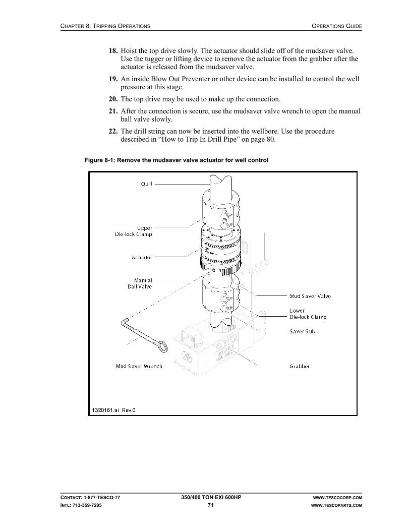
CHAPTER 8: TRIPPING OPERATIONS OPERATIONS GUIDE
CONTACT: 1-877-TESCO-77 350/400 TON EXI 600HP WWW.TESCOCORP.COM
INTL: 713-359-7295 71 WWW.TESCOPARTS.COM
18. Hoist the top drive slowly. The actuator should slide off of the mudsaver valve. Use the tugger or lifting device to remove the actuator from the grabber after the actuator is released from the mudsaver valve.
19. An inside Blow Out Preventer or other device can be installed to control the well pressure at this stage.
20. The top drive may be used to make up the connection.
21. After the connection is secure, use the mudsaver valve wrench to open the manual ball valve slowly.
22. The drill string can now be inserted into the wellbore. Use the procedure described in “How to Trip In Drill Pipe” on page 80.
Figure 8-1: Remove the mudsaver valve actuator for well control
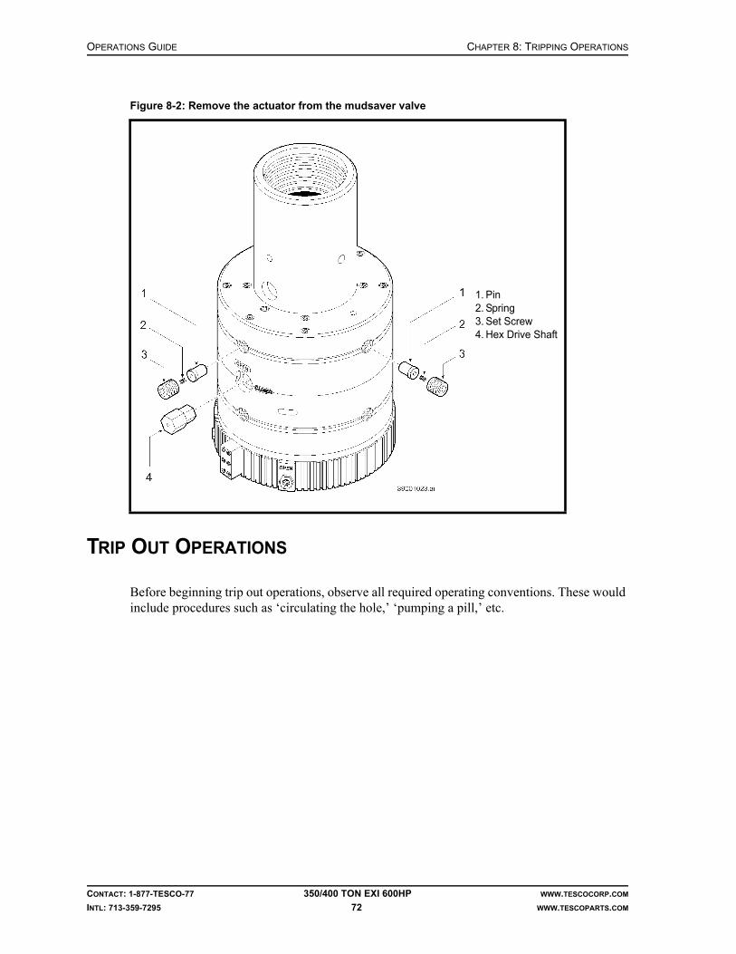
OPERATIONS GUIDE CHAPTER 8: TRIPPING OPERATIONS
CONTACT: 1-877-TESCO-77 350/400 TON EXI 600HP WWW.TESCOCORP.COM
INTL: 713-359-7295 72 WWW.TESCOPARTS.COM
TRIP OUT OPERATIONS
Before beginning trip out operations, observe all required operating conventions. These would include procedures such as ‘circulating the hole,’ ‘pumping a pill,’ etc.
Figure 8-2: Remove the actuator from the mudsaver valve
1. Pin2. Spring3. Set Screw4. Hex Drive Shaft

CHAPTER 8: TRIPPING OPERATIONS OPERATIONS GUIDE
CONTACT: 1-877-TESCO-77 350/400 TON EXI 600HP WWW.TESCOCORP.COM
INTL: 713-359-7295 73 WWW.TESCOPARTS.COM
How to Trip Out Drill PipeFigure 8-3: Trip out drill pipe
OPERATIONS GUIDE CHAPTER 8: TRIPPING OPERATIONS
CONTACT: 1-877-TESCO-77 350/400 TON EXI 600HP WWW.TESCOCORP.COM
INTL: 713-359-7295 74 WWW.TESCOPARTS.COM
Caution: Ensure that the pipe handler is oriented such that the links can be tilted toward the derrickman when the drill pipe is ready to be racked.
1. Shut off the rig mud pumps.
2. Monitor the standpipe gauge to ensure that mud pump pressure decreases to zero.
3. Set the VALVE switch to ‘CLOSE’.
4. Hoist the top drive.
5. Set the slips.Note: Ensure the stored torque in the drill string has dissipated before the slips are set.
6. Position the elevator on the drill pipe using the TILT function.
7. Set the ELEVATOR switch to ‘CLOSE’.
8. Hoist or lower the top drive until the grabber is positioned on the tool joint of the drill pipe.
9. Set the GRABBER switch to ‘CLOSE’.
10. Set the MODE switch to ‘CONN’.
11. Set the QUILL switch to ‘REV’.Note: The top drive torque will increase to the preset torque value for reverse rotation.
12. Press and hold the BREAKOUT button.Note: The top drive torque will increase to the break out torque value for the unit.
13. When the connection loosens and the quill rotates 1/2 turn, release the BREAKOUT button.
14. Immediately set the GRABBER switch to ‘OPEN’.Note: This raises the top drive in small increments as the connection unscrews.
15. Lead the top drive out of the drill pipe connection.Note: To avoid damaging the pipe threads, do not allow the weight of the top drive to sit on the connection while it unscrews.
16. When the top drive clears the connection, set the QUILL switch to neutral.
17. Hoist the top drive and drill pipe.
18. Remove the slips.
19. Hoist the top drive to lift the drill pipe (single, double or stand) above the rotary table.
20. Set the slips.
21. Use tongs to break the stump connection, then unscrew the connection by using chain tongs or a pipe spinner.
22. Hoist the drill pipe clear of the stump.
23. Proceed with the standard racking procedure. See “Standard Racking Procedure” on page 75.
24. Lower the top drive and grab the drill string stump with the elevator.
25. Repeat steps 17 to 24 to trip out the rest of the drill string.
!

CHAPTER 8: TRIPPING OPERATIONS OPERATIONS GUIDE
CONTACT: 1-877-TESCO-77 350/400 TON EXI 600HP WWW.TESCOCORP.COM
INTL: 713-359-7295 75 WWW.TESCOPARTS.COM
Standard Racking Procedure
1. Hoist the drill pipe (single, double or triple stand) until the bottom is above the floor racking area.
Note: Elevator links will have to be set to vertical/hole center to avoid hitting the racking board.
2. Set the TILT switch to ‘FWD’.
3. Allow the rig floor personnel to push the bottom of the stand into place on the racking floor.
4. Set the stand down in the racking area.
5. Position the tip of the stand where the derrickman can easily reach and take control of it.
6. Wait until the stand is secured and the derrickman is ready to take control of the stand.
7. Push and hold the ELEVATOR SAFETY OPEN button.
8. Set the ELEVATOR switch to ‘OPEN’.
9. Press the FLOAT button.
10. Lower the top drive to receive the next section of pipe.
Caution: In cold weather operations mud can freeze within the com-ponents. To prevent freezing, air blow the top drive, kelly hose and stand pipe back to tank after pulling 4-5 stands of free pipe and when stopping for a flow check. If the mud valve is to be closed for any length of time in extreme weather conditions, the same proce-dures apply.
How to Trip Out BHA (Collars and Tools)
This procedure assumes that all drill pipe has been removed from the wellbore and that the first collar is above the rotary table.
Note: Ensure that the pipe handler is oriented such that the links can be tilted toward the derrickman when the collars are ready to be racked.
!

OPERATIONS GUIDE CHAPTER 8: TRIPPING OPERATIONS
CONTACT: 1-877-TESCO-77 350/400 TON EXI 600HP WWW.TESCOCORP.COM
INTL: 713-359-7295 76 WWW.TESCOPARTS.COM
Figure 8-4: Trip out collars

CHAPTER 8: TRIPPING OPERATIONS OPERATIONS GUIDE
CONTACT: 1-877-TESCO-77 350/400 TON EXI 600HP WWW.TESCOCORP.COM
INTL: 713-359-7295 77 WWW.TESCOPARTS.COM
1. Set the slips.
2. Attach a safety clamp.
3. Ensure that the elevator and elevator links are hanging vertically.
4. Set the PIPE HANDLER switch to ‘UNLOCK’.
5. Set and hold the PIPE HANDLER switch at FWD position.Note: The pipe handler will begin to rotate at the preset speed.
6. Position the pipe handler so that the TILT feature can be used to assist in racking the collars.
7. When the pipe handler is in the proper position, release the PIPE HANDLER switch from ‘FWD’ to neutral position.
8. Set the PIPE HANDLER switch to ‘LOCK’.
9. Use the TILT feature to position the top drive elevator to accept a pick-up sub.
10. Set the ELEVATOR switch to ‘CLOSE’.
11. Hoist the top drive to position the pick-up sub above the collar.
12. Push the FLOAT button. This allows the elevator and pick-up sub to 'float' to hole center.
13. Lower the top drive to stab the pick-up sub into the top collar.
14. Use chain tongs to fully engage the connection between the pick-up sub and the collar.
Caution: Torque the connection to prevent it from unscrewing.
15. Remove the safety clamp.
16. Hoist the top drive and remove the slips.
17. Hoist the top drive until the required number of collars are above the rotary table.
18. Set the slips and attach a safety clamp.
19. Use rig tongs to break the connection between the collar segments.
20. When the connection is loosened, use the pipe handler, rotary table or chain tongs to fully unscrew the connection.
21. Hoist the collar(s).
22. Allow rig floor personnel to position the bottom of the collar for racking.
23. Use the TILT feature to tilt the collar(s) toward the derrickman.Note: The EXTEND function can also be used.
24. When the derrickman has control of the collar(s), set the ELEVATOR switch to OPEN, and push and hold the ELEVATOR SAFETY OPEN button.
25. Release the collar(s) and the pick-up sub.Note: The pick-up sub will remain on the collar(s) to facilitate ‘trip in’ operations.
26. Repeat this procedure for each collar or stand of collars.
!
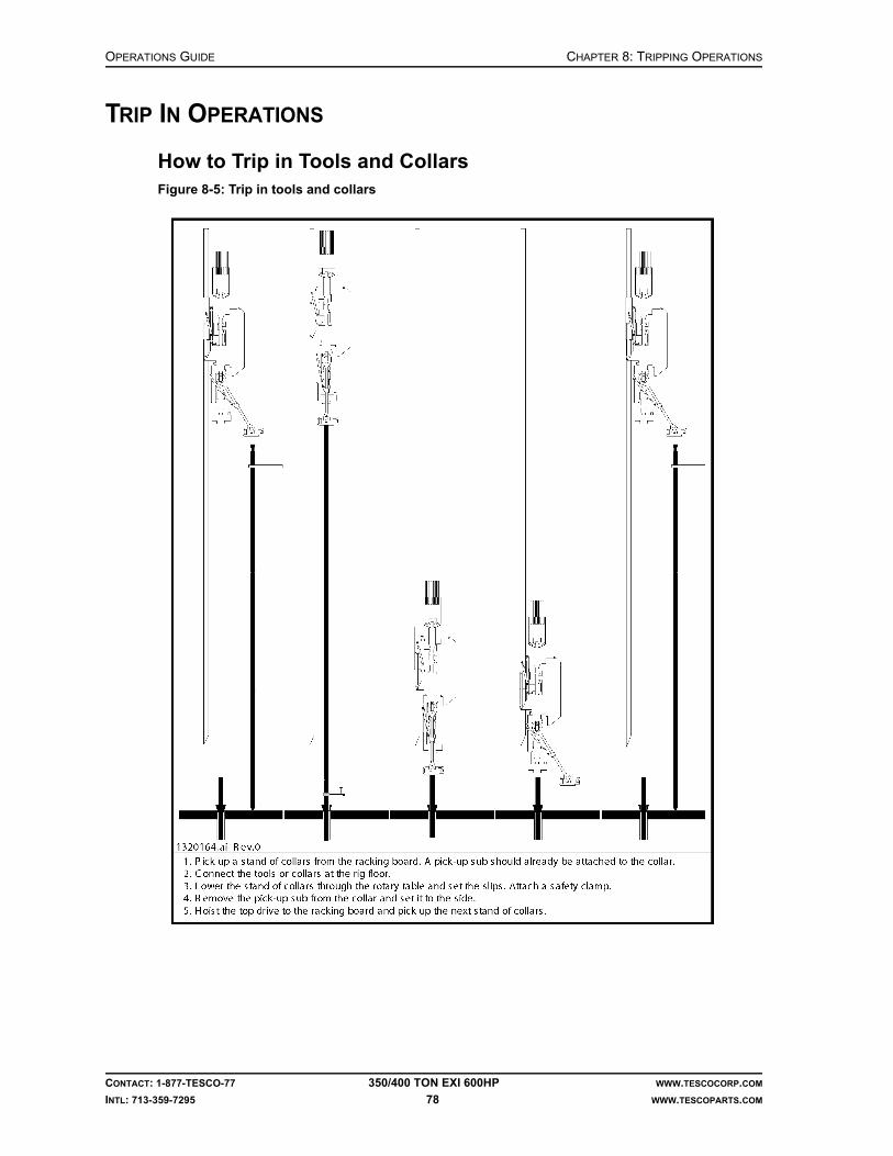
OPERATIONS GUIDE CHAPTER 8: TRIPPING OPERATIONS
CONTACT: 1-877-TESCO-77 350/400 TON EXI 600HP WWW.TESCOCORP.COM
INTL: 713-359-7295 78 WWW.TESCOPARTS.COM
TRIP IN OPERATIONS
How to Trip in Tools and CollarsFigure 8-5: Trip in tools and collars

CHAPTER 8: TRIPPING OPERATIONS OPERATIONS GUIDE
CONTACT: 1-877-TESCO-77 350/400 TON EXI 600HP WWW.TESCOCORP.COM
INTL: 713-359-7295 79 WWW.TESCOPARTS.COM
1. Use the top drive to lower the first section (bit and tools) into the rotary table.Note: If acceptable, the floor tugger may also be used to perform this step.
2. Set the slips and, if applicable, attach a safety clamp.
3. Use the rig tongs to break out the joint of the pick-up sub.
4. Set the ELEVATOR switch to ‘OPEN’, and push and hold the ELEVATOR SAFETY OPEN button.
5. Hoist the top drive to the racking platform.
6. Use the chain tongs to unscrew the pick-up sub.
7. Use the floor tugger to remove the pick-up sub.
8. Set the TILT switch to ‘FWD’.
9. Use the EXTEND function, if necessary, to accept the first collar from the derrick-man.
10. Position the elevator on the collar of the pick-up sub.
11. Set the ELEVATOR button to ‘CLOSE’.
12. Hoist the top drive and the stand of collars/tools from the racking area.
13. Press the FLOAT button. This will bring elevator and elevator links to the vertical position.
Caution: If using the EXTEND function, bring the top drive to the IN position.
14. Allow rig personnel to hold the bottom of the stand and carefully move it to hole center.
15. Lower the top drive and stab the lower connection.
16. Use the pipe handler, chain tongs or spinning chain to connect the collar to the stump.
17. Use rig tongs to torque the connection to specification.
18. Remove the safety clamp.
19. Hoist the top drive and the drill string.
20. Remove the slips.
21. Lower the stand of collars/tools through the rotary table to the appropriate height for the next connection.
22. Set the slips and install a safety clamp.
23. Use the rig tongs to break out the pick-up sub.
24. Use the chain tongs to unscrew the pick-up sub from the top collar.
25. Use the TILT switch to bring the elevator forward and position the pick-up sub where it can be removed from the rig floor by using the floor tugger.
26. Set the ELEVATOR switch to ‘OPEN’, and push and hold the ELEVATOR SAFETY OPEN button.
27. Hoist the top drive and pick up the next collar or stand of collars.
28. Repeat this procedure for all collars.Note: When all collars have been tripped in, the pipe handler must be oriented to pick up drill pipe.
!

OPERATIONS GUIDE CHAPTER 8: TRIPPING OPERATIONS
CONTACT: 1-877-TESCO-77 350/400 TON EXI 600HP WWW.TESCOCORP.COM
INTL: 713-359-7295 80 WWW.TESCOPARTS.COM
How to Trip In Drill Pipe
1. Ensure that the elevator and elevator links are hanging vertically.
2. Set the PIPE HANDLER switch to ‘UNLOCK’.
3. Set and hold the PIPE HANDLER switch to ‘FWD’.Note: The pipe handler will begin to rotate at the preset speed.
4. When the pipe handler is in the proper position, release the PIPE HANDLER switch from ‘FWD’ to neutral position.
5. Set the PIPE HANDLER switch to ‘LOCK’.
6. Hoist the top drive to the racking platform.
7. Use the TILT switch to tilt the links forward to accept the first drill pipe or stand of drill pipe from the derrickman.
8. Position the elevator on the drill pipe.
9. Set the ELEVATOR switch to ‘CLOSE’.
10. Hoist the top drive and drill pipe off the racking area.
11. Press the FLOAT button to bring the elevator and elevator links to hole center.
12. Allow rig personnel to hold the bottom of the pipe and move it into position.
13. Lower the top drive and stab the connection.
14. Connect the drill pipe using the chain tongs, spinning chain, or pipe spinner.
15. Use rig tongs to torque the connection to specification.
16. Hoist the top drive and the drill pipe.
17. Remove the slips.
18. Lower the top drive and drill string.
19. Lower the stand of drill pipe through the rotary table to the appropriate height for the next connection.
20. Set the slips.
21. Set ELEVATOR switch to ‘OPEN’.
22. Repeat this procedure for all single lengths or stands of drill pipe that are tripped into the wellbore.

CHAPTER 8: TRIPPING OPERATIONS OPERATIONS GUIDE
CONTACT: 1-877-TESCO-77 350/400 TON EXI 600HP WWW.TESCOCORP.COM
INTL: 713-359-7295 81 WWW.TESCOPARTS.COM
REAMING OPERATIONS
How to Use the Top Drive to Ream During Trip Out Operations
• Ream: to enlarge the diameter of a wellbore.
Reaming is performed whenever a tight spot is encountered during trip out operations. This most commonly occurs when a collar encounters an obstruction or a narrowing in the open hole.
If using the top drive to perform tripping operations, the drill pipe and bottom hole assembly (BHA–tools and collars) will be suspended from the top drive elevator. In order to ream, the top drive must be connected to the drill string and the tight section must be worked until the drill string can pass freely. To continue tripping operations after the obstruction is cleared, the top drive must be disconnected and the drill string suspended from the elevator.
Use the following procedure if encountering a tight spot while tripping out (the weight indicator displays more than the weight of the drill string), or if the drill string is stuck:
1. Lower the top drive and the drill string.Note: Ensure that the uppermost drill pipe connection is in position to connect to the top drive.
2. Set the slips.
3. Lower the top drive until the saver sub contacts the drill pipe.
4. Use the grabber lift needle valves to position the grabber on the box connection of the drill pipe.
5. Set the GRABBER switch to ‘CLOSE’.
6. Set the MODE switch to ‘CONNECT’.
7. Set the QUILL switch to ‘FWD’.
8. Use the TORQUE switch to increase the torque to 30 to 40% of the maximum connect values required for the thread and connection type.
9. Lower the top drive into the connection.Note: Do not allow the top drive weight to sit on the threaded connection.
10. Fully engage the connection between the saver sub and the drill pipe.
11. Use the TORQUE switch to increase the torque to the make up value required for the thread and connection type.
12. When the torque reaches the required torque for the connection, set the QUILL switch to neutral.
13. Set the GRABBER switch to ‘OPEN’.
14. Set the mudsaver VALVE switch to ‘OPEN’.
15. Start the mud pumps.
16. Set the MODE switch to ‘DRILL’.
17. Set the QUILL switch to ‘FWD’.
18. Set speed and torque to the required values.

OPERATIONS GUIDE CHAPTER 8: TRIPPING OPERATIONS
CONTACT: 1-877-TESCO-77 350/400 TON EXI 600HP WWW.TESCOCORP.COM
INTL: 713-359-7295 82 WWW.TESCOPARTS.COM
19. Hoist the top drive until the tight spot is encountered.
20. Raise and lower the top drive several times (or until the hole is clean) while circulating the mud.
Note: It is advisable to trip out one or two stands with the top drive connected to the drill string.
21. When reaming operations are complete, set the QUILL switch to select neutral.
22. Hoist top drive to the proper position for disconnecting it from the drill pipe.
23. Set the slips.
24. Turn off the rig mud pumps.
25. Set the mudsaver VALVE switch to ‘CLOSE’
26. Disconnect the drill pipe from the top drive. See “How to Break the Top Drive/Drill Pipe Connection” on page 44 for more information.
27. Continue with standard procedures for trip out operations.
How to Use the Top Drive to Ream to Bottom During Trip In Operations
• Ream: to enlarge the diameter of a wellbore.
Reaming to bottom is performed whenever a tight spot is encountered during trip in operations.
If using the top drive for tripping operations, the drill pipe or BHA (tools and collars) will be suspended from the top drive elevator. In order to ream ahead, the top drive must be connected to the drill string and the tight section must be worked until the drill string can pass freely. To continue tripping operations after the obstruction is cleared, the top drive must be discon-nected and the drill string suspended from the elevator.
Use the following procedure if encountering a tight spot during trip in operations (weight comes off the weight indicator).
1. Hoist the top drive to lift the bottom hole assembly (BHA) above the tight spot.Note: Ensure that the uppermost drill pipe connection is in position to connect to the top drive.
2. Set the slips.
3. Lower the top drive until the saver sub contacts the drill pipe.
4. Use the grabber lift needle valves to position the grabber on the box connection of the drill pipe.
5. Set the GRABBER switch to ‘CLOSE’.
6. Set the MODE switch to ‘CONN’.
7. Set the QUILL switch to ‘FWD’.
8. Rotate the top drive into the connection.Note: Do not allow the top drive weight to sit on the threaded connection.
9. Fully engage the connection between the saver sub and the drill pipe.

CHAPTER 8: TRIPPING OPERATIONS OPERATIONS GUIDE
CONTACT: 1-877-TESCO-77 350/400 TON EXI 600HP WWW.TESCOCORP.COM
INTL: 713-359-7295 83 WWW.TESCOPARTS.COM
10. Use the TORQUE switch to increase the torque to the value required to make up the thread and connection type.
11. When the torque reaches the required torque for the connection, set the QUILL switch to neutral.
12. Set the GRABBER switch to ‘OPEN’.
13. Set the mudsaver VALVE switch to ‘OPEN’.
14. Start the mud pumps.
15. Set the MODE switch to ‘DRILL’.
16. Set the QUILL switch to ‘FWD’.
17. Set the speed and torque to the required values for drilling operations.
18. Lower the top drive until the tight spot is encountered.
19. Raise and lower the top drive several times (or until the hole is clean) while circulating the mud.
Note: It is advisable to trip in one or two stands with the top drive connected to the drill string.
20. When reaming is complete, set the switch to neutral.
21. Hoist or lower the top drive to the proper position for disconnecting it from the drill pipe.
22. Set the slips.
23. Turn off the mud pumps.
24. Set the mudsaver VALVE switch to ‘CLOSE’.
25. Disconnect the drill pipe from the top drive. See “How to Break the Top Drive/Drill Pipe Connection” on page 44 for additional information.
26. Continue with standard procedures for trip in operations.

OPERATIONS GUIDE CHAPTER 8: TRIPPING OPERATIONS
CONTACT: 1-877-TESCO-77 350/400 TON EXI 600HP WWW.TESCOCORP.COM
INTL: 713-359-7295 84 WWW.TESCOPARTS.COM
This page has been left blank intentionally.
CHAPTER 9: STUCK PIPE OPERATIONS GUIDE
CONTACT: 1-877-TESCO-77 350/400 TON EXI 600HP WWW.TESCOCORP.COM
INTL: 713-359-7295 85 WWW.TESCOPARTS.COM
CHAPTER 9: STUCK PIPE
Unlike conventional Kelly systems, TESCO top drives help maintain mud circulation and torque on the drill pipe while pulling or jar stuck drill pipe.
HOW TO USE THE TOP DRIVE TO FREE STUCK PIPE
1. Connect the top drive to the drill string.
2. If possible, maintain mud pump flow.
3. Set the MODE switch to ‘DRILL’.
4. Set speed to the required value.
5. Set the torque to the required value.Note: Drill torque is typically 80% of make up torque. Refer to “How to Set or Change Drive Parameters” on page 26.
6. Set the QUILL switch to ‘FWD’.
7. Raise and lower the top drive to work the drill string up and down.
8. Continue to raise and lower the top drive and drill string until a free point is estab-lished.
9. When the drill string begins to rotate, raise and lower the top drive in the free point area in small increments.
Warning! When jarring with torque in the drill string, carefully monitor the condition of the torque bushing and torque tube.
10. Gradually increase the travel distance until the obstruction is cleared.
!
OPERATIONS GUIDE CHAPTER 9: STUCK PIPE
CONTACT: 1-877-TESCO-77 350/400 TON EXI 600HP WWW.TESCOCORP.COM
INTL: 713-359-7295 86 WWW.TESCOPARTS.COM
HOW TO USE THE TOP DRIVE FOR JARRING OPERATIONS
If the drill pipe cannot be freed by using the top drive as described in the previous procedure, ‘jarring’ operations may need to be initiated.
TESCO does not recommend jarring the drill string while the drill pipe is suspended from the elevator. If access to the drill pipe is absolutely necessary (for wireline or logging, for exam-ple), then ensure that the elevator is closed and the elevator hydraulic hoses are removed.
Note: Torque can be applied when working or jarring pipe, if necessary.
Warning! Always exercise extreme care when ‘jarring’ with torque in the drill string. Monitor the torque bushing and travel assembly carefully for the duration of the jarring operation.
1. Ensure that the top drive is connected to the drill string.
2. Maintain mud pump flow if possible.
3. Close the elevator on the drill pipe.
4. Set the MODE switch to ‘DRILL’.
5. Set the speed to the required value.Note: Recommended speed is 30 to 40 rpm.
6. Set the torque to the required valueNote: Drill torque is typically 80% of make up torque. Refer to “How to Set or Change Drive Parameters” on page 26.
7. Set the QUILL switch to ‘FWD’.
8. Initiate jarring operations; use the top drive to hoist and lower the drill string.
9. When the string begins to rotate, raise and lower the top drive in the free point area in small increments.
10. Gradually increase the travel distance until the obstruction is cleared.
Warning! To help ensure the functional integrity of the top drive, perform a ‘post jarring check’ after any jarring operation. Refer to ‘Appendix 1: Post Jarring Checklist’.
Warning! If jarring operations exceed eight hours, or if jarring is extremely rough, a complete load path inspection must be performed at the first available opportunity.
!
!
!

CHAPTER 9: STUCK PIPE OPERATIONS GUIDE
CONTACT: 1-877-TESCO-77 350/400 TON EXI 600HP WWW.TESCOCORP.COM
INTL: 713-359-7295 87 WWW.TESCOPARTS.COM
CONTROLLED DRILL STRING BACK OFF OPERATIONS
In some cases it is necessary to separate the stuck portion of the drill string from the free length (to ‘back off’ the drill string). This is best accomplished by applying reverse torque to the connection immediately above the stuck point, and then deploying an explosive charge at the connection.
The decision to back off a drill string has significant financial and operational implica-tions. Back off of a drill string should never be authorized or undertaken until all inter-ested parties have agreed to the procedure.
1. Set the DRILL torque for reverse rotation to 70% of the make up torque.Note: See “How to Set or Change Drive Parameters” on page 26 for more information.
2. Position wireline tools and the charge device at the connection where the drill string is to be disconnected.
3. Set the MODE switch to ‘DRILL’.
4. Set the QUILL switch to ‘REV’.
5. Work the drill pipe up and down and slowly increase the quill speed in very small increments.
Note: Torque is assumed to be at its limit when the pipe will not rotate any further. If it is necessary to increase the torque in stages, adjust the drill-reverse torque setting as the torque in the drill string is being increased. If a specific number of rotations of the drill pipe is required, increase the torque until the required number of rotations is achieved.
6. When the correct amount of torque has been put into the drill string (indicated when the correct torque value appears on the torque gauge and the pipe stops turn-ing), then close the grabber.
7. Set the QUILL switch to neutral.
8. Reposition the blocks.
Caution: The blocks should be positioned to achieve neutral weight at the connection to be shot. This means that the weight indicator reading should equal the weight of the free portion of drill pipe.
!

OPERATIONS GUIDE CHAPTER 9: STUCK PIPE
CONTACT: 1-877-TESCO-77 350/400 TON EXI 600HP WWW.TESCOCORP.COM
INTL: 713-359-7295 88 WWW.TESCOPARTS.COM
9. When neutral weight is established, fire the explosive charge.
10. Monitor the weight indicator and string rotation.
When the drill pipe is free, the drill string should rotate freely. If the pipe has parted at the correct location, the weight indicator reading should not change significantly.
Caution: If the weight indicator falls, this may indicate that the drill pipe has parted above the expected connection. If this occurs, do not hoist. It might be possible to re-establish the connection. Evalu-ate the situation before proceeding.
11. Open the grabber.
12. Ensure that the drill string is free by doing the following:• confirm free rotation of pipe• hoist carefully to confirm that the rotating pipe is not stuck (using override)
13. Trip out the first stand of pipe from the hole while it is connected to the top drive.
14. When first stand is racked, break the top drive connection.
15. Continue with normal tripping operations.
UNCONTROLLED PARTING OF THE DRILL STRING
Warning! If the drill string parts in an uncontrolled manner at any time, a post jarring inspection MUST be performed before drilling operations commence. Refer to “Appendix A: Post Jarring Checklist”.
Figure 9-1: Neutral weight at the connection
Total weight of pipe downhole = 125,000 lbWeight of pipe below the stuck point = 65,000 lb
Total weight of the free pipe = 60,000 lb
The weight indicator will display 60,000 lb when the first free connection is at neutral.
!
!

CHAPTER 10: RUN AND PULL CASING OPERATIONS GUIDE
CONTACT: 1-877-TESCO-77 350/400 TON EXI 600HP WWW.TESCOCORP.COM
INTL: 713-359-7295 89 WWW.TESCOPARTS.COM
CHAPTER 10: RUN AND PULL CASING
There are advantages to using the TESCO top drive to run casing:
• Fill-up tools can be connected directly to the top drive to provide fill-up capability while running the casing.
• The TILT and EXTEND functions can be used to assist rig personnel in handling and stabbing the casing.
Figure 10-1: Pick up casing
1. Floor slip elevators2. Working platform
(optional)3. Sling4. Casing Running
elevators5. Pick-up elevators

OPERATIONS GUIDE CHAPTER 10: RUN AND PULL CASING
CONTACT: 1-877-TESCO-77 350/400 TON EXI 600HP WWW.TESCOCORP.COM
INTL: 713-359-7295 90 WWW.TESCOPARTS.COM
PREPARE THE TOP DRIVE TO RUN CASING
1. If required, orient the pipe handler so that the elevator links can be tilted toward the V-door.
2. Remove the hydraulic elevator from the elevator links.
3. If required, remove the elevator links.Note: Longer elevator links are often required when casing is being run. Use the floor tugger to attach the longer links.
Caution: If using elevator links longer than 12 ft (3.7 m), do not use the LINK TILT function. Consult a TESCO representative if links longer than 12 ft (3.7 m) must be used.
4. Pick up the casing running elevators.
5. If casing fill-up apparatus is required, use the grabber and the top drive to connect it to the top drive saver sub.
6. If using the top drive to bring casing up the V-door and onto the rig floor, use a set of pick-up elevators and slings:• Attach the ‘pick-up elevator’ slings such that the single-joint pick-up elevators
hang approximately 3 to 4 ft (0.9 to 1.2 m) below the main elevator.• Attach the ‘pick-up elevator’ slings to the pick-up elevators.
7. Ensure that a working platform and floor elevators are installed and operational if required.
Warning! Use a crane or a “tail-in” line to assist in lifting large diameter, heavy weight casing from the V-door to the rig floor. If this precaution is not taken, the weight of the casing will pull the top drive away from the torque track. This can damage the EXTEND components of the torque arrest system.
!
!

CHAPTER 10: RUN AND PULL CASING OPERATIONS GUIDE
CONTACT: 1-877-TESCO-77 350/400 TON EXI 600HP WWW.TESCOCORP.COM
INTL: 713-359-7295 91 WWW.TESCOPARTS.COM
HOW TO RUN CASING
1. Attach the pick-up elevators to the first joint of casing.Note: If required, use the EXTEND and TILT functions to extend the reach.
Caution: Whenever possible, use the EXTEND and TILT functions to reduce the stress on the torque track.
Figure 10-2: Run casing
!

OPERATIONS GUIDE CHAPTER 10: RUN AND PULL CASING
CONTACT: 1-877-TESCO-77 350/400 TON EXI 600HP WWW.TESCOCORP.COM
INTL: 713-359-7295 92 WWW.TESCOPARTS.COM
2. Ensure that floor personnel are ready to control the bottom of the casing joint.
3. Slowly hoist the top drive to move the casing to the drill floor.
Warning! The weight of the casing tends to pull the top drive away from the torque track. This strains the stabilization devices for the torque track.
Warning! If the top drive is extended toward the casing when hoisted, it could collide with the racking platform.
4. Hoist the casing until it is above the rig floor.
5. Lower the casing into the wellbore to the desired connection height.
6. Set the slips onto the casing.
7. Attach a safety clamp.
8. Unlatch the pick-up elevators.
9. If required, lower the top drive to stab the fill-up tool into the casing stump.
10. Fill the casing as required.
11. Repeat Steps 1 to 4 for the second joint of casing, then continue with the follow-ing steps.
12. Lower the second joint of casing until its pin end enters the box end of the casing in the slips.
Note: The TILT and EXTEND functions can also be used to assist in aligning the casing joints.
13. Use casing tongs to make up the casing connection.
14. After the connection is made up securely, remove the pick-up elevators.
15. Latch the casing running elevators onto the top joint of casing.
16. Remove the safety clamp.
17. Hoist the casing.
Figure 10-3: Reduce the stress on the torque track
Incorrect Good Better
!
!

CHAPTER 10: RUN AND PULL CASING OPERATIONS GUIDE
CONTACT: 1-877-TESCO-77 350/400 TON EXI 600HP WWW.TESCOCORP.COM
INTL: 713-359-7295 93 WWW.TESCOPARTS.COM
18. Remove the slips.
19. Lower the casing into the wellbore to the desired connection height.
20. Attach a safety clamp.
21. Set the slips on the casing.
22. Unlatch the casing running elevators.
23. If required, lower the top drive the stab the fill-up tool into the casing stump.
24. Fill the casing as required.
25. Repeat this procedure as required for all joints of casing.
HOW TO PULL CASING
1. Attach casing running elevators to the top joint of casing.
2. Remove the slips.
3. Hoist the top drive until the entire joint of casing is above the rig floor.
4. Set the slips.
5. Unlatch the running elevators from the casing.
6. Attach the pick-up elevators to the casing.
7. Use casing tongs to break and unscrew the casing connection.
8. Hoist the top drive and the casing joint.
9. Use the EXTEND and TILT functions to move the casing toward the V-door.
10. Ensure that rig personnel are in place to guide the bottom of the casing joint.
11. Lower the top drive slowly and allow floor personnel to control the bottom of the casing.
12. When the casing is secured in the V-door, unlatch the pick-up elevators.
13. Repeat this procedure for all casing joints.
Caution: When reaching the last few lengths of casing, it may be necessary to use a safety clamp to ensure the casing does not slide through the slips.
!

OPERATIONS GUIDE CHAPTER 10: RUN AND PULL CASING
CONTACT: 1-877-TESCO-77 350/400 TON EXI 600HP WWW.TESCOCORP.COM
INTL: 713-359-7295 94 WWW.TESCOPARTS.COM
This page has been left blank intentionally.
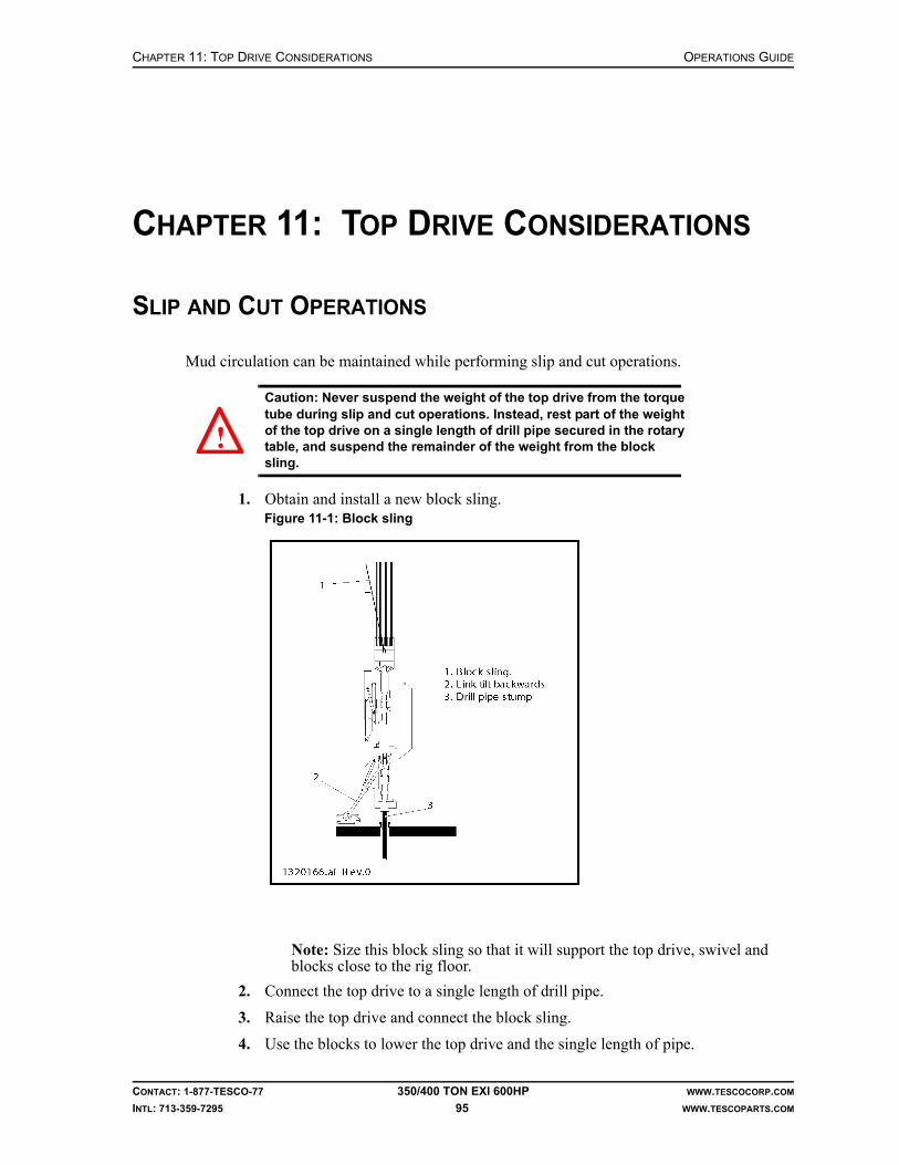
CHAPTER 11: TOP DRIVE CONSIDERATIONS OPERATIONS GUIDE
CONTACT: 1-877-TESCO-77 350/400 TON EXI 600HP WWW.TESCOCORP.COM
INTL: 713-359-7295 95 WWW.TESCOPARTS.COM
CHAPTER 11: TOP DRIVE CONSIDERATIONS
SLIP AND CUT OPERATIONS
Mud circulation can be maintained while performing slip and cut operations.
Caution: Never suspend the weight of the top drive from the torque tube during slip and cut operations. Instead, rest part of the weight of the top drive on a single length of drill pipe secured in the rotary table, and suspend the remainder of the weight from the block sling.
1. Obtain and install a new block sling.
Note: Size this block sling so that it will support the top drive, swivel and blocks close to the rig floor.
2. Connect the top drive to a single length of drill pipe.
3. Raise the top drive and connect the block sling.
4. Use the blocks to lower the top drive and the single length of pipe.
Figure 11-1: Block sling
!
OPERATIONS GUIDE CHAPTER 11: TOP DRIVE CONSIDERATIONS
CONTACT: 1-877-TESCO-77 350/400 TON EXI 600HP WWW.TESCOCORP.COM
INTL: 713-359-7295 96 WWW.TESCOPARTS.COM
5. Lower the pipe through the rotary table.Note: To lower the top drive to the rig floor, tilt the links as far back as possible. Maintain enough clearance so that the front cover of the drawworks can be removed for servicing.
6. When the block sling is almost tight, stop lowering the top drive.Note: Balance the weight of the top drive between the block hanging sling and the pipe in the slips.
7. Set the slips.
CEMENTING OPERATIONS
Do not run cement through the top drive unless it is absolutely necessary. Cement causes wear and, if allowed to harden, will irreparably damage the top drive.
If suspending a cement head from the top drive elevator ensure the following conditions exist:
• The elevator links are long enough to accommodate the cement head.• The elevator hydraulic hoses are disconnected.
Note: Disconnect the hydraulic hose when the cement head is in position and the elevators are closed.
When using a flow-through cement head, some cement might enter the quill and mud valve. After completing cementing operations, TESCO advises that the quill, mudsaver valve and lower Kelly valve be flushed thoroughly. Operate the mudsaver and Kelly valves to ensure they work properly.
Danger! Failure to perform these operational checks can compromise rig safety!
SLICKLINE SURVEY AND WIRELINE LOGGING OPERATIONS
Several issues must be addressed when using a top drive for slickline or wireline operations.
When using a turn-down sheave, use the following conventions:
• Orient the elevator links so they are parallel to the direction of line travel.• Remove the elevator hydraulic hoses when suspending the turn-down sheave from the
elevator. This prevents accidental opening of the elevator.
!

CHAPTER 11: TOP DRIVE CONSIDERATIONS OPERATIONS GUIDE
CONTACT: 1-877-TESCO-77 350/400 TON EXI 600HP WWW.TESCOCORP.COM
INTL: 713-359-7295 97 WWW.TESCOPARTS.COM
TESCO’s wireline/slickline guide attaches to the front of the grabber. The guide leads the wireline/slickline from the front of the top drive to the center of the hole. Guide rollers prevent the line from running over sharp corners that can cause damage.
If using the wireline/slickline guide, place the grabber leg in the fully ‘up’ position, if possible.
Elevator Links
Elevator
Correct Incorrect
Grabber Leg
Grabber Box
Guide Roller

OPERATIONS GUIDE CHAPTER 11: TOP DRIVE CONSIDERATIONS
CONTACT: 1-877-TESCO-77 350/400 TON EXI 600HP WWW.TESCOCORP.COM
INTL: 713-359-7295 98 WWW.TESCOPARTS.COM
HEAVY LOADS AT THE V-DOOR
This procedure describes how to use the top drive to pick up heavy loads from the V-door.
Warning! The extend frame and EXTEND function handle drilling tools, pick up casing, and rack drill pipe and collars. They are for convenience only and are not designed to pick-up heavy loads while extended.
Warning! Exercise care, attention and common sense when applying the following procedure to pick up heavy loads from the V-door using the top drive.
1. Connect the elevator links on the top drive to the load being picked up. Use slings that are strong enough to support the load.
2. Connect a rig winch to the load being picked up.
3. Hoist the top drive with the extend frame completely retracted until the slings are tight and the top drive is beginning to pick up the load.
4. At this point, hold the EXTEND switch at the IN position to maintain pressure on the extend cylinders. This will prevent the extend frame from “opening up” while the load is lifted. The force of gravity, combined with the load and the angle at which it is being lifted, will tend to pull the extend frame open.
5. If the load is too heavy, and holding the EXTEND switch in the IN position is not sufficient to keep the extend frame retracted, pick up the load with the rig winch. This will create less pull on the extend frame and allow it to stay retracted. The top drive, with the extend frame retracted, can be hoisted vertically with no chance of the torque bushing binding on the torque track.
6. Continue to hoist the load until it is at the level required.
Warning! The extend frame must remain retracted at all times when hoisting any heavy load. If it is allowed to extend, the torque bushing can bind on the torque track and damage the extend frame and extend cylinders. For this reason, always use a rig winch to help lift the load. If done carefully, most normal drilling equipment can be lifted using the above procedure.
Warning! For extremely heavy loads, TESCO recommends using either additional winches to assist in the lift or use cranes to position the equipment on the drill floor instead of picking them up with the top drive. Damage to the top drive and unnecessary repair time can be avoided with proper planning and preparation.
!
!
!
!

APPENDIX A: POST JARRING CHECKLIST OPERATIONS GUIDE
CONTACT: 1-877-TESCO-77 350/400 TON EXI 600HP WWW.TESCOCORP.COM
INTL: 713-359-7295 99 WWW.TESCOPARTS.COM
APPENDIX A: POST JARRING CHECKLIST

OPERATIONS GUIDE APPENDIX A: POST JARRING CHECKLIST
CONTACT: 1-877-TESCO-77 350/400 TON EXI 600HP WWW.TESCOCORP.COM
INTL: 713-359-7295 100 WWW.TESCOPARTS.COM
This page has been left blank intentionally.

INDEX OPERATIONS GUIDE
CONTACT: 1-877-TESCO-77 350/400 TON EXI 600HP WWW.TESCOCORP.COM
INTL: 713-359-7295 101 WWW.TESCOPARTS.COM
INDEX
Aabout the top drive, 1AUX PUMP switch, 13
BBHA
make up, 50trip in, 78trip out, 75
brake handle, 21elevator-close, 21
BREAKOUT push button, 15, 20BREAKOUT speed, set, 27
Ccautions
collars, 51elevator links, 51EXTEND function, 46grabber override, 52making or breaking connections, 37mudsaver valve, 37pick-up sub, 51slips, 37tilt links, 39trapped torque, 37Vernier dampening valve, 39
collars and toolsmake up, 50
CONNECT Forwardset speed, 27set torque, 27
CONNECT modeforward rotation, 20forward speed, 20forward torque, 20reverse rotation, 20reverse speed, 20reverse torque, 20
CONNECT Reverseset speed, 27set torque, 27
connectionsbreak connection to top drive, 44cautions, 37connect collars above the rotary table, 52connect pipe single to drill sting, 42general overview, 38
how to connect drill pipe at the mousehole, 39how to fully torque, 42make up BHA (collars and tools), 50make up pipe stands, 48make up triples, 47make up with grabber to drawworks, 41make up with grabber to V-door, 39mousehole, 39
DDELIVERED SPEED calibration, 22DELIVERED SPEED meter, 15DELIVERED TORQUE
how to calibrate, 22die lock clamp installation, 31DNm, 15DRILL mode
forward rotation, 19forward speed, 19forward torque, 19reverse rotation, 19reverse speed, 19reverse torque, 19
drill pipeconnect to the drill string, 42connect to the top drive at the mousehole, 39make connections, general, 38make up triples, 47
DRILL Reverseset speed, 27set torque, 27
driller’s panelcalibrate meters, 21controls, 12drive controls and indicators, 14E.S.D., 18features, 11general description, 3, 11indicators, 12meters, 15quill controls, 15robotic functions, 13switch naming convention, 15warning lights, 12
drive controls and indicators, 14drive parameters
BREAKOUT speed, 27CONNECT Forward, 27CONNECT Reverse, 27

OPERATIONS GUIDE INDEX
CONTACT: 1-877-TESCO-77 350/400 TON EXI 600HP WWW.TESCOCORP.COM
INTL: 713-359-7295 102 WWW.TESCOPARTS.COM
DRILL Reverse, 27how to set or change, 26overview, 26
DRIVE SET switch, 14
EELEVATOR function description, 16ELEVATOR switch, 13ELEVATOR-CLOSE
brake handle, 21ELEVATOR-SAFETY-OPEN, 16emergency shut down (E.S.D.)
description, 18on the driller’s panel, 18on the main panel, 18push button, 14reset, 18
ENABLE switch, 14EXTEND function
cautions, 46description, 16
EXTEND switch, 13
FFLOAT push button, 13function descriptions
ELEVATOR, 16EXTEND, 16GRABBER, 17PIPE HANDLER, 18TILT, 16VALVE, 17
GGRABBER ’CLOSED’ light, 14GRABBER function description, 17GRABBER switch, 14GRABBER-Drawworks override, 21
Iinformation, where to find more, 1
Mmake connections
general, 38precautions, 38
metersdriller’s panel, 15how to calibrate, 21, 22
MODE switch, 15MODULE ’ON’ light, 14mousehole
make up stands, 48use to make connections, 39
mudsaver valvecautions, 37
Nnaming conventions for switch settings, 15
Ooverride
ELEVATOR-CLOSE, 21GRABBER-Drawworks, 21
Ppipe
break connection with top drive, 44connect to drill string, 42make up triples, 47
pipe handlerfunction description, 18
PIPE HANDLER ’CAUTION’ light, 14PIPE HANDLER ROTATE push button, 14PIPE HANDLER switch, 14pipe stands
make up in mousehole, 48make up in rotary table, 45
pre-operational proceduresinstall the die lock clamp, 31install the saver sub, 31
Qquill rotation controls, 15QUILL switch, 15
RREADY light, 14remote brake handle, 21RESET push button, 14robotic functions
controls and indicators, 13ROBOTICS ’ON’ light, 13rotary table
connect collars, 52make up pipe stands, 45
SSAFETY OPEN push button, 13saver sub installation, 31SET SPEED
how to calibrate, 22SET TORQUE calibration, 22SET TORQUE meter, 15

INDEX OPERATIONS GUIDE
CONTACT: 1-877-TESCO-77 350/400 TON EXI 600HP WWW.TESCOCORP.COM
INTL: 713-359-7295 103 WWW.TESCOPARTS.COM
speed available, 19SPEED switch, 15System Description, 3
TTILT function description, 16TILT switch, 13torque
trapped in drill string, 37torque available, 19torque meter, display DNm, 15TORQUE switch, 15torquing connections, 42
VVALVE ’CLOSED’ light, 14VALVE function description, 17VALVE switch, 13

OPERATIONS GUIDE INDEX
CONTACT: 1-877-TESCO-77 350/400 TON EXI 600HP WWW.TESCOCORP.COM
INTL: 713-359-7295 104 WWW.TESCOPARTS.COM
This page has been left blank intentionally.

OPERATIONS GUIDE
CONTACT: 1-877-TESCO-77 350/400 TON EXI 600HP WWW.TESCOCORP.COM
INTL: 713-359-7295 105 WWW.TESCOPARTS.COM
ENGINEERING SIGN-OFF
This sign-off sheet indicates that this document has been approved for release by the Engineering Department at TESCO.
Document Complete By Signature Date Signed
Document Reviewed/Approved Date Signed
chane
Typewritten Text
Edward ChanFeb 4, 2010
madejskm
Typewritten Text
Feb 4, 2010

OPERATIONS GUIDE
CONTACT: 1-877-TESCO-77 350/400 TON EXI 600HP WWW.TESCOCORP.COM
INTL: 713-359-7295 106 WWW.TESCOPARTS.COM
This page has been left blank intentionally.

DOCUMENT NAME: 880079 REV 2
Maintenance Guide
EXI Top Drive System
350/400 TON EXI 600HP

COPYRIGHT AND DISCLAIMER MAINTENANCE GUIDE
CONTACT: 1-877-TESCO-77 350/400 TON EXI 600HP WWW.TESCOCORP.COM
INTL: 713-359-7295 I WWW.TESCOPARTS.COM
Tesco Corporation (“TESCO”) has made every effort to ensure that this document contains accurate and current information for the TESCO top drive, however, the document is intended to be used in conjunction with a complete training program and on-site supervision and TESCO does not warrant or guarantee that the information contained herein is either complete or accurate in every respect, and the reader hereby protects, indemnifies and holds harmless Tesco Corporation together with its directors, officers, employees and agents from and against all liability for personal injury, death or property damage to any person arising directly or indirectly from the use by the reader of the information contained in the document.
This equipment was filled at the factory with TESCO ULTREX™ brand fluids and greases. To ensure maximum performance and to avoid cross-contamination, we strongly recommend the continued usage of TESCO ULTREX™ lubricants, unless otherwise specified.
TESCO ULTREX™ is a trademark and TESCO® is a registered trademark of Tesco Corporation.
Tesco Corporation © 2009
Contact Information
Corporate Head Office3993 W. Sam Houston Parkway No., Suite 100
Houston, Texas, 77043USA
www.tescocorp.comwww.tescoparts.com
Telephone: (713) 359-7000Fax: (713) 359-7001
After Market Sales and Service ContactToll Free North America: 1-877-TESCO-77
International: 713-359-7295

REVISION INFORMATION MAINTENANCE GUIDE
CONTACT: 1-877-TESCO-77 350/400 TON EXI 600HP WWW.TESCOCORP.COM
INTL: 713-359-7295 II WWW.TESCOPARTS.COM
Revision Information
Version Date Description of Changes
Rev 0 August 2007 First release of document
Rev 1 October 2008 Upgrade 350 EXI 600 to 350/400 EXI 600
Rev 2 September 2009 Added TESCO ULTREX™ recommendations and updated the footer to contain contact information.

TABLE OF CONTENTS MAINTENANCE GUIDE
CONTACT: 1-877-TESCO-77 350/400 TON EXI 600HP WWW.TESCOCORP.COM
INTL: 713-359-7295 III WWW.TESCOPARTS.COM
TABLE OF CONTENTS
LIST OF FIGURES . . . . . . . . . . . . . . . . . . . . . . . . . . . . . . . . . . . . . . . . . . . . . . . . . . . . . 1
LIST OF TABLES . . . . . . . . . . . . . . . . . . . . . . . . . . . . . . . . . . . . . . . . . . . . . . . . . . . . . . 1
SAFETY INSTRUCTIONS . . . . . . . . . . . . . . . . . . . . . . . . . . . . . . . . . . . . . . . . . . . . . . . . . 3
CHAPTER 1: ABOUT THIS DOCUMENT . . . . . . . . . . . . . . . . . . . . . . . . . . . . . . . . . . . . . . 1
CHAPTER 2: MAINTENANCE AND SERVICE SCHEDULES . . . . . . . . . . . . . . . . . . . . . . . . . 3
Lock-Out Methods. . . . . . . . . . . . . . . . . . . . . . . . . . . . . . . . . . . . . . . . . . . . . . . . . . . . . . . . . . . . . . . . . 3
Fluid Specification and Capacity Summary . . . . . . . . . . . . . . . . . . . . . . . . . . . . . . . . . . . . . . . . . . . . 5
Top Drive Service Requirements . . . . . . . . . . . . . . . . . . . . . . . . . . . . . . . . . . . . . . . . . . . . . . . . . . . . . 5
Daily Top Drive Service . . . . . . . . . . . . . . . . . . . . . . . . . . . . . . . . . . . . . . . . . . . . . . . . . . . . . . . . . . 5
Inspection. . . . . . . . . . . . . . . . . . . . . . . . . . . . . . . . . . . . . . . . . . . . . . . . . . . . . . . . . . . . . . . . . . . . . . . . . . . . . . . . . . . . . . . 5
Lubrication . . . . . . . . . . . . . . . . . . . . . . . . . . . . . . . . . . . . . . . . . . . . . . . . . . . . . . . . . . . . . . . . . . . . . . . . . . . . . . . . . . . . . . 6
Weekly Top Drive Service . . . . . . . . . . . . . . . . . . . . . . . . . . . . . . . . . . . . . . . . . . . . . . . . . . . . . . . . 6
Monthly (Periodic) Top Drive Service . . . . . . . . . . . . . . . . . . . . . . . . . . . . . . . . . . . . . . . . . . . . . . . . 7
Six-Month Top Drive Service . . . . . . . . . . . . . . . . . . . . . . . . . . . . . . . . . . . . . . . . . . . . . . . . . . . . . . 8
1,000 Operating Day Top Drive Service. . . . . . . . . . . . . . . . . . . . . . . . . . . . . . . . . . . . . . . . . . . . . . 8
Driller’s Panel Service Requirements . . . . . . . . . . . . . . . . . . . . . . . . . . . . . . . . . . . . . . . . . . . . . . . . 11
Monthly Driller’s Panel Service. . . . . . . . . . . . . . . . . . . . . . . . . . . . . . . . . . . . . . . . . . . . . . . . . . . . 11
Service Loop Service Requirements . . . . . . . . . . . . . . . . . . . . . . . . . . . . . . . . . . . . . . . . . . . . . . . . . 11
Weekly Service Loop Service. . . . . . . . . . . . . . . . . . . . . . . . . . . . . . . . . . . . . . . . . . . . . . . . . . . . . 11
Monthly (Periodic) Service Loop Service . . . . . . . . . . . . . . . . . . . . . . . . . . . . . . . . . . . . . . . . . . . . 11
1,000 Operating Day Service Loop Service . . . . . . . . . . . . . . . . . . . . . . . . . . . . . . . . . . . . . . . . . . 12
Torque Arrest System Service Requirements . . . . . . . . . . . . . . . . . . . . . . . . . . . . . . . . . . . . . . . . . 12
Daily Torque Arrest System Service. . . . . . . . . . . . . . . . . . . . . . . . . . . . . . . . . . . . . . . . . . . . . . . . 12
Weekly Torque Arrest System Service. . . . . . . . . . . . . . . . . . . . . . . . . . . . . . . . . . . . . . . . . . . . . . 12
Auxiliary Hydraulic Power Unit Service Requirements . . . . . . . . . . . . . . . . . . . . . . . . . . . . . . . . . . 13
Daily Auxiliary Hydraulic Power Unit Service . . . . . . . . . . . . . . . . . . . . . . . . . . . . . . . . . . . . . . . . . 13
Weekly Auxiliary Hydraulic Power Unit Service . . . . . . . . . . . . . . . . . . . . . . . . . . . . . . . . . . . . . . . 13
Monthly (Periodic) Auxiliary Hydraulic Power Unit Service . . . . . . . . . . . . . . . . . . . . . . . . . . . . . . 13
1,000 Operating Day Auxiliary Hydraulic Power Unit Service . . . . . . . . . . . . . . . . . . . . . . . . . . . . 14
Power Module Service Requirements . . . . . . . . . . . . . . . . . . . . . . . . . . . . . . . . . . . . . . . . . . . . . . . . 14
Daily Power Module Service. . . . . . . . . . . . . . . . . . . . . . . . . . . . . . . . . . . . . . . . . . . . . . . . . . . . . . 14
Condensation . . . . . . . . . . . . . . . . . . . . . . . . . . . . . . . . . . . . . . . . . . . . . . . . . . . . . . . . . . . . . . . . . 14
Weekly Power Module Service. . . . . . . . . . . . . . . . . . . . . . . . . . . . . . . . . . . . . . . . . . . . . . . . . . . . 15
Monthly (Periodic) Power Module Service . . . . . . . . . . . . . . . . . . . . . . . . . . . . . . . . . . . . . . . . . . . 15

MAINTENANCE GUIDE TABLE OF CONTENTS
CONTACT: 1-877-TESCO-77 350/400 TON EXI 600HP WWW.TESCOCORP.COM
INTL: 713-359-7295 IV WWW.TESCOPARTS.COM
CHAPTER 3: NON-DESTRUCTIVE TESTING AND INSPECTION SCHEDULES . . . . . . . . . . . .17
Top Drive Owner’s Guidelines . . . . . . . . . . . . . . . . . . . . . . . . . . . . . . . . . . . . . . . . . . . . . . . . . . . . . .17
Guidelines for Component Inspectors. . . . . . . . . . . . . . . . . . . . . . . . . . . . . . . . . . . . . . . . . . . . . . . .18
Load Path Components and Inspection Information . . . . . . . . . . . . . . . . . . . . . . . . . . . . . . . . . . . .18
Inspection Types . . . . . . . . . . . . . . . . . . . . . . . . . . . . . . . . . . . . . . . . . . . . . . . . . . . . . . . . . . . . . . .19
Threaded Connections . . . . . . . . . . . . . . . . . . . . . . . . . . . . . . . . . . . . . . . . . . . . . . . . . . . . . . . . . . . .29
Threaded Connection Inspection Frequency (EXI 600) . . . . . . . . . . . . . . . . . . . . . . . . . . . . . . . . .29
Torque Arrest System . . . . . . . . . . . . . . . . . . . . . . . . . . . . . . . . . . . . . . . . . . . . . . . . . . . . . . . . . . . . .29
CHAPTER 4: SERVICE PROCEDURES . . . . . . . . . . . . . . . . . . . . . . . . . . . . . . . . . . . . . . .37
Introduction . . . . . . . . . . . . . . . . . . . . . . . . . . . . . . . . . . . . . . . . . . . . . . . . . . . . . . . . . . . . . . . . . . . . .37
How to Disassemble and Service the Roto-Actuator . . . . . . . . . . . . . . . . . . . . . . . . . . . . . . . . . . . .40
Re-assembly . . . . . . . . . . . . . . . . . . . . . . . . . . . . . . . . . . . . . . . . . . . . . . . . . . . . . . . . . . . . . . . . . .41
How to Set the Counter-Balance Cushion Height. . . . . . . . . . . . . . . . . . . . . . . . . . . . . . . . . . . . . . .42
How to Set the Secondary Pressure Relief Valve for the Auxiliary System . . . . . . . . . . . . . . . . . .44
How to Set the Main Pressure Relief Valve for the Auxiliary System . . . . . . . . . . . . . . . . . . . . . . .45
How to Set the Function Light Pressure Switch for the Auxiliary System . . . . . . . . . . . . . . . . . . .46
How to Check and Adjust Preload for the Quill Upper Bearing. . . . . . . . . . . . . . . . . . . . . . . . . . . .47
How to Check for Quill End Play . . . . . . . . . . . . . . . . . . . . . . . . . . . . . . . . . . . . . . . . . . . . . . . . . . .47
How to Calculate the Preload Adjustment. . . . . . . . . . . . . . . . . . . . . . . . . . . . . . . . . . . . . . . . . . . .48
How to Adjust the Preload. . . . . . . . . . . . . . . . . . . . . . . . . . . . . . . . . . . . . . . . . . . . . . . . . . . . . . . .49
CHAPTER 5: DISASSEMBLY AND ASSEMBLY INSTRUCTIONS . . . . . . . . . . . . . . . . . . . . . .51Install the Mudsaver Valve . . . . . . . . . . . . . . . . . . . . . . . . . . . . . . . . . . . . . . . . . . . . . . . . . . . . . . .51
How to Disassemble and Assemble the Grabber . . . . . . . . . . . . . . . . . . . . . . . . . . . . . . . . . . . . . . .53
Introduction . . . . . . . . . . . . . . . . . . . . . . . . . . . . . . . . . . . . . . . . . . . . . . . . . . . . . . . . . . . . . . . . . . .53
How to Change the Grabber Dies . . . . . . . . . . . . . . . . . . . . . . . . . . . . . . . . . . . . . . . . . . . . . . . . . .53
How to Remove the Grabber Actuating Piston . . . . . . . . . . . . . . . . . . . . . . . . . . . . . . . . . . . . . . . .54
How to Reinstall the Grabber Actuating Piston . . . . . . . . . . . . . . . . . . . . . . . . . . . . . . . . . . . . . . . .56
How to Repair the Grabber Cylinder . . . . . . . . . . . . . . . . . . . . . . . . . . . . . . . . . . . . . . . . . . . . . . . .56
How to Remove and Reinstall the Grabber Leg . . . . . . . . . . . . . . . . . . . . . . . . . . . . . . . . . . . . . . .57
Remove the Grabber Leg . . . . . . . . . . . . . . . . . . . . . . . . . . . . . . . . . . . . . . . . . . . . . . . . . . . . . . . . . . . . . . . . . . . . . . . . . . 58
Reinstall the Grabber Leg. . . . . . . . . . . . . . . . . . . . . . . . . . . . . . . . . . . . . . . . . . . . . . . . . . . . . . . . . . . . . . . . . . . . . . . . . . 58
CHAPTER 6: LONG TERM PRESERVATION AND STORAGE. . . . . . . . . . . . . . . . . . . . . . . .59
Introduction . . . . . . . . . . . . . . . . . . . . . . . . . . . . . . . . . . . . . . . . . . . . . . . . . . . . . . . . . . . . . . . . . . . . .59
Before System Shut Down . . . . . . . . . . . . . . . . . . . . . . . . . . . . . . . . . . . . . . . . . . . . . . . . . . . . . . . . .59
Top Drive. . . . . . . . . . . . . . . . . . . . . . . . . . . . . . . . . . . . . . . . . . . . . . . . . . . . . . . . . . . . . . . . . . . . . . . .60
Junction Boxes . . . . . . . . . . . . . . . . . . . . . . . . . . . . . . . . . . . . . . . . . . . . . . . . . . . . . . . . . . . . . . . .60
Motor Termination Junction Boxes . . . . . . . . . . . . . . . . . . . . . . . . . . . . . . . . . . . . . . . . . . . . . . . . . . . . . . . . . . . . . . . . . . . 60
Top Drive Junction Box. . . . . . . . . . . . . . . . . . . . . . . . . . . . . . . . . . . . . . . . . . . . . . . . . . . . . . . . . . . . . . . . . . . . . . . . . . . . 60

TABLE OF CONTENTS MAINTENANCE GUIDE
CONTACT: 1-877-TESCO-77 350/400 TON EXI 600HP WWW.TESCOCORP.COM
INTL: 713-359-7295 V WWW.TESCOPARTS.COM
Quill . . . . . . . . . . . . . . . . . . . . . . . . . . . . . . . . . . . . . . . . . . . . . . . . . . . . . . . . . . . . . . . . . . . . . . . . 60
Load Nut (where applicable). . . . . . . . . . . . . . . . . . . . . . . . . . . . . . . . . . . . . . . . . . . . . . . . . . . . . . 60
Grabber Leg . . . . . . . . . . . . . . . . . . . . . . . . . . . . . . . . . . . . . . . . . . . . . . . . . . . . . . . . . . . . . . . . . . 61
Pipe Handler. . . . . . . . . . . . . . . . . . . . . . . . . . . . . . . . . . . . . . . . . . . . . . . . . . . . . . . . . . . . . . . . . . 61
Hydraulics. . . . . . . . . . . . . . . . . . . . . . . . . . . . . . . . . . . . . . . . . . . . . . . . . . . . . . . . . . . . . . . . . . . . 61
Swivel Links, Yoke, and Counter Balance . . . . . . . . . . . . . . . . . . . . . . . . . . . . . . . . . . . . . . . . . . . 61
Extend Frame and Mount . . . . . . . . . . . . . . . . . . . . . . . . . . . . . . . . . . . . . . . . . . . . . . . . . . . . . . . . 62
Elevators. . . . . . . . . . . . . . . . . . . . . . . . . . . . . . . . . . . . . . . . . . . . . . . . . . . . . . . . . . . . . . . . . . . . . 62
Mudsaver Valve . . . . . . . . . . . . . . . . . . . . . . . . . . . . . . . . . . . . . . . . . . . . . . . . . . . . . . . . . . . . . . . 62
Saver Subs . . . . . . . . . . . . . . . . . . . . . . . . . . . . . . . . . . . . . . . . . . . . . . . . . . . . . . . . . . . . . . . . . . . 63
Service Loop Storage Reel, Cables and Hoses . . . . . . . . . . . . . . . . . . . . . . . . . . . . . . . . . . . . . . . . 63
Driller’s Panel . . . . . . . . . . . . . . . . . . . . . . . . . . . . . . . . . . . . . . . . . . . . . . . . . . . . . . . . . . . . . . . . . . . 63
Interlocks . . . . . . . . . . . . . . . . . . . . . . . . . . . . . . . . . . . . . . . . . . . . . . . . . . . . . . . . . . . . . . . . . . . . 64
Torque Arrest System. . . . . . . . . . . . . . . . . . . . . . . . . . . . . . . . . . . . . . . . . . . . . . . . . . . . . . . . . . . . . 64
Torque Track Assembly . . . . . . . . . . . . . . . . . . . . . . . . . . . . . . . . . . . . . . . . . . . . . . . . . . . . . . . . . 64
Torque Bushing/Extend Frame. . . . . . . . . . . . . . . . . . . . . . . . . . . . . . . . . . . . . . . . . . . . . . . . . . . . 64
Hanging Assembly . . . . . . . . . . . . . . . . . . . . . . . . . . . . . . . . . . . . . . . . . . . . . . . . . . . . . . . . . . . . . 65
Torque Beam and T-Bar. . . . . . . . . . . . . . . . . . . . . . . . . . . . . . . . . . . . . . . . . . . . . . . . . . . . . . . . . 65
Hose Saddle and Components. . . . . . . . . . . . . . . . . . . . . . . . . . . . . . . . . . . . . . . . . . . . . . . . . . . . 65
Hydraulic Power Unit . . . . . . . . . . . . . . . . . . . . . . . . . . . . . . . . . . . . . . . . . . . . . . . . . . . . . . . . . . . . . 65
General. . . . . . . . . . . . . . . . . . . . . . . . . . . . . . . . . . . . . . . . . . . . . . . . . . . . . . . . . . . . . . . . . . . . . . 65
Auxiliary Hydraulics . . . . . . . . . . . . . . . . . . . . . . . . . . . . . . . . . . . . . . . . . . . . . . . . . . . . . . . . . . . . 65
Power Module . . . . . . . . . . . . . . . . . . . . . . . . . . . . . . . . . . . . . . . . . . . . . . . . . . . . . . . . . . . . . . . . . . . 66
Incoming Waterfall . . . . . . . . . . . . . . . . . . . . . . . . . . . . . . . . . . . . . . . . . . . . . . . . . . . . . . . . . . . . . 66
600 VAC Panel . . . . . . . . . . . . . . . . . . . . . . . . . . . . . . . . . . . . . . . . . . . . . . . . . . . . . . . . . . . . . . . . 66
120/208 VAC Panel . . . . . . . . . . . . . . . . . . . . . . . . . . . . . . . . . . . . . . . . . . . . . . . . . . . . . . . . . . . . 66
Drive System . . . . . . . . . . . . . . . . . . . . . . . . . . . . . . . . . . . . . . . . . . . . . . . . . . . . . . . . . . . . . . . . . 66
Drive Output Waterfall . . . . . . . . . . . . . . . . . . . . . . . . . . . . . . . . . . . . . . . . . . . . . . . . . . . . . . . . . . 66
APPENDIX A: TORQUE STANDARDS FOR HIGH STRENGTH FASTENERS. . . . . . . . . . . . . 67
Purpose . . . . . . . . . . . . . . . . . . . . . . . . . . . . . . . . . . . . . . . . . . . . . . . . . . . . . . . . . . . . . . . . . . . . . . . . 67
Standards. . . . . . . . . . . . . . . . . . . . . . . . . . . . . . . . . . . . . . . . . . . . . . . . . . . . . . . . . . . . . . . . . . . . . . . 67
Tables . . . . . . . . . . . . . . . . . . . . . . . . . . . . . . . . . . . . . . . . . . . . . . . . . . . . . . . . . . . . . . . . . . . . . . . . . . 68
APPENDIX B: TOOL JOINT USAGE CHART . . . . . . . . . . . . . . . . . . . . . . . . . . . . . . . . . . 71
APPENDIX C: MUD LOGGER OUTPUTS. . . . . . . . . . . . . . . . . . . . . . . . . . . . . . . . . . . . . 73
APPENDIX D: TORQUE SPECIFICATION OF ELECTRICAL FASTENERS . . . . . . . . . . . . . . . 75
APPENDIX E: SAMPLE INSPECTION LOGS . . . . . . . . . . . . . . . . . . . . . . . . . . . . . . . . . . 77
Quill Inspection Log . . . . . . . . . . . . . . . . . . . . . . . . . . . . . . . . . . . . . . . . . . . . . . . . . . . . . . . . . . . . . . 78
Load Nut Retainer and Split Collar Inspection Log . . . . . . . . . . . . . . . . . . . . . . . . . . . . . . . . . . . . 79
MAINTENANCE GUIDE TABLE OF CONTENTS
CONTACT: 1-877-TESCO-77 350/400 TON EXI 600HP WWW.TESCOCORP.COM
INTL: 713-359-7295 VI WWW.TESCOPARTS.COM
Mudsaver Valve Inspection Log . . . . . . . . . . . . . . . . . . . . . . . . . . . . . . . . . . . . . . . . . . . . . . . . . . . .80
Saver Sub Inspection Log . . . . . . . . . . . . . . . . . . . . . . . . . . . . . . . . . . . . . . . . . . . . . . . . . . . . . . . . .81
Load Collar Inspection Log . . . . . . . . . . . . . . . . . . . . . . . . . . . . . . . . . . . . . . . . . . . . . . . . . . . . . . . .82
Elevator Links Inspection Log . . . . . . . . . . . . . . . . . . . . . . . . . . . . . . . . . . . . . . . . . . . . . . . . . . . . . .83
Elevator Inspection Log . . . . . . . . . . . . . . . . . . . . . . . . . . . . . . . . . . . . . . . . . . . . . . . . . . . . . . . . . . .84
APPENDIX F: SERVICE CHECKLISTS . . . . . . . . . . . . . . . . . . . . . . . . . . . . . . . . . . . . . . .85
Daily Checklists . . . . . . . . . . . . . . . . . . . . . . . . . . . . . . . . . . . . . . . . . . . . . . . . . . . . . . . . . . . . . . . . . .85
Daily: Top Drive. . . . . . . . . . . . . . . . . . . . . . . . . . . . . . . . . . . . . . . . . . . . . . . . . . . . . . . . . . . . . . . .85
Daily: Torque Arrest System . . . . . . . . . . . . . . . . . . . . . . . . . . . . . . . . . . . . . . . . . . . . . . . . . . . . . .86
Daily: Auxiliary Hydraulic Power Unit . . . . . . . . . . . . . . . . . . . . . . . . . . . . . . . . . . . . . . . . . . . . . . .86
Daily: Power Module . . . . . . . . . . . . . . . . . . . . . . . . . . . . . . . . . . . . . . . . . . . . . . . . . . . . . . . . . . . .86
Weekly Checklists . . . . . . . . . . . . . . . . . . . . . . . . . . . . . . . . . . . . . . . . . . . . . . . . . . . . . . . . . . . . . . . .87
Weekly: Top Drive . . . . . . . . . . . . . . . . . . . . . . . . . . . . . . . . . . . . . . . . . . . . . . . . . . . . . . . . . . . . . .87
Weekly: Service Loop . . . . . . . . . . . . . . . . . . . . . . . . . . . . . . . . . . . . . . . . . . . . . . . . . . . . . . . . . . .87
Weekly: Torque Arrest System . . . . . . . . . . . . . . . . . . . . . . . . . . . . . . . . . . . . . . . . . . . . . . . . . . . .88
Weekly: Auxiliary Hydraulic Power Unit . . . . . . . . . . . . . . . . . . . . . . . . . . . . . . . . . . . . . . . . . . . . .88
Weekly: Power Module . . . . . . . . . . . . . . . . . . . . . . . . . . . . . . . . . . . . . . . . . . . . . . . . . . . . . . . . . .88
Monthly Checklists . . . . . . . . . . . . . . . . . . . . . . . . . . . . . . . . . . . . . . . . . . . . . . . . . . . . . . . . . . . . . . .89
Monthly: Top Drive . . . . . . . . . . . . . . . . . . . . . . . . . . . . . . . . . . . . . . . . . . . . . . . . . . . . . . . . . . . . .89
Monthly Driller’s Panel. . . . . . . . . . . . . . . . . . . . . . . . . . . . . . . . . . . . . . . . . . . . . . . . . . . . . . . . . . .90
Monthly: Service Loop. . . . . . . . . . . . . . . . . . . . . . . . . . . . . . . . . . . . . . . . . . . . . . . . . . . . . . . . . . .90
Monthly: Auxiliary Hydraulic Power Unit . . . . . . . . . . . . . . . . . . . . . . . . . . . . . . . . . . . . . . . . . . . . .90
Monthly: Power Module. . . . . . . . . . . . . . . . . . . . . . . . . . . . . . . . . . . . . . . . . . . . . . . . . . . . . . . . . .91
Megger Test Chart . . . . . . . . . . . . . . . . . . . . . . . . . . . . . . . . . . . . . . . . . . . . . . . . . . . . . . . . . . . . . . . .92
Motor and Pigtail . . . . . . . . . . . . . . . . . . . . . . . . . . . . . . . . . . . . . . . . . . . . . . . . . . . . . . . . . . . . . . .92
Service Loop . . . . . . . . . . . . . . . . . . . . . . . . . . . . . . . . . . . . . . . . . . . . . . . . . . . . . . . . . . . . . . . . . .92
TESCO Ultrex™ Lubricants. . . . . . . . . . . . . . . . . . . . . . . . . . . . . . . . . . . . . . . . . . . . . . . . . . . . . . . . .93
Quick Reference Guide . . . . . . . . . . . . . . . . . . . . . . . . . . . . . . . . . . . . . . . . . . . . . . . . . . . . . . . . . .93
Oil Lubricants . . . . . . . . . . . . . . . . . . . . . . . . . . . . . . . . . . . . . . . . . . . . . . . . . . . . . . . . . . . . . . . . .94
Grease Lubricants . . . . . . . . . . . . . . . . . . . . . . . . . . . . . . . . . . . . . . . . . . . . . . . . . . . . . . . . . . . . .100
INDEX. . . . . . . . . . . . . . . . . . . . . . . . . . . . . . . . . . . . . . . . . . . . . . . . . . . . . . . . . . . . .105

LIST OF FIGURES MAINTENANCE GUIDE
CONTACT: 1-877-TESCO-77 350/400 TON EXI 600HP WWW.TESCOCORP.COM
INTL: 713-359-7295 1 WWW.TESCOPARTS.COM
LIST OF FIGURES
Figure 2-1: Lubrication points for the 350T EXI 600 Top Drive . . . . . . . . . . . . . . . . . . . . . . . . . . . . . . . . 9Figure 2-2: Lubrication points for the 400T EXI 600 Top Drive . . . . . . . . . . . . . . . . . . . . . . . . . . . . . . . 10Figure 3-1: Yoke and link assembly (350 EXI 600) . . . . . . . . . . . . . . . . . . . . . . . . . . . . . . . . . . . . . . . . 19Figure 3-2: Yoke and Link assembly (400 EXI 600) . . . . . . . . . . . . . . . . . . . . . . . . . . . . . . . . . . . . . . . 20Figure 3-3: Swivel gearbox housing (EXI 600) . . . . . . . . . . . . . . . . . . . . . . . . . . . . . . . . . . . . . . . . . . . 21Figure 3-4: Quill (EXI 600). . . . . . . . . . . . . . . . . . . . . . . . . . . . . . . . . . . . . . . . . . . . . . . . . . . . . . . . . . . 22Figure 3-5: Load nut components (EXI 600) . . . . . . . . . . . . . . . . . . . . . . . . . . . . . . . . . . . . . . . . . . . . . 23Figure 3-6: Mudsaver valve and actuator (EXI 600) . . . . . . . . . . . . . . . . . . . . . . . . . . . . . . . . . . . . . . . 24Figure 3-7: Saver sub (EXI 600) . . . . . . . . . . . . . . . . . . . . . . . . . . . . . . . . . . . . . . . . . . . . . . . . . . . . . . 25Figure 3-8: Load collar (EXI 600) . . . . . . . . . . . . . . . . . . . . . . . . . . . . . . . . . . . . . . . . . . . . . . . . . . . . . 26Figure 3-9: Elevator links (bails) (EXI 600) . . . . . . . . . . . . . . . . . . . . . . . . . . . . . . . . . . . . . . . . . . . . . . 27Figure 3-10: Elevators (EXI 600). . . . . . . . . . . . . . . . . . . . . . . . . . . . . . . . . . . . . . . . . . . . . . . . . . . . . . 28Figure 3-11: Non-destructive testing for the standard torque arrest system (EXI 600) . . . . . . . . . . . . . 30Figure 3-12: Non-destructive inspection of PH-rotation system components (EXI 600) . . . . . . . . . . . . 32Figure 3-13: Inspection of gearbox (EXI 600) . . . . . . . . . . . . . . . . . . . . . . . . . . . . . . . . . . . . . . . . . . . . 34Figure 4-1: General maintenance areas (350 EXI 600) . . . . . . . . . . . . . . . . . . . . . . . . . . . . . . . . . . . . 38Figure 4-2: General maintenance areas (400 EXI 600) . . . . . . . . . . . . . . . . . . . . . . . . . . . . . . . . . . . . 39Figure 4-3: Actuator/valve orientation . . . . . . . . . . . . . . . . . . . . . . . . . . . . . . . . . . . . . . . . . . . . . . . . . . 41Figure 4-4: Counter-balance cushion height (350 EXI 600) . . . . . . . . . . . . . . . . . . . . . . . . . . . . . . . . . 43Figure 4-5: Counter-balance cushion height (400 EXI 600) . . . . . . . . . . . . . . . . . . . . . . . . . . . . . . . . . 44Figure 4-6: Auxiliary system main pressure relief valve . . . . . . . . . . . . . . . . . . . . . . . . . . . . . . . . . . . . 45Figure 4-7: Auxiliary hydraulic system schematic . . . . . . . . . . . . . . . . . . . . . . . . . . . . . . . . . . . . . . . . . 46Figure 4-8: Measure the quill hub endplay . . . . . . . . . . . . . . . . . . . . . . . . . . . . . . . . . . . . . . . . . . . . . . 48Figure 4-9: Preload adjustment . . . . . . . . . . . . . . . . . . . . . . . . . . . . . . . . . . . . . . . . . . . . . . . . . . . . . . . 49Figure 5-1: How to use blocks to raise the mudsaver valve . . . . . . . . . . . . . . . . . . . . . . . . . . . . . . . . . 51Figure 5-2: Grabber box components . . . . . . . . . . . . . . . . . . . . . . . . . . . . . . . . . . . . . . . . . . . . . . . . . . 55Figure 5-3: Grabber leg assembly. . . . . . . . . . . . . . . . . . . . . . . . . . . . . . . . . . . . . . . . . . . . . . . . . . . . . 57Figure C-1: Checking analog mud logger outputs. . . . . . . . . . . . . . . . . . . . . . . . . . . . . . . . . . . . . . . . . 73

MAINTENANCE GUIDE LIST OF FIGURES
CONTACT: 1-877-TESCO-77 350/400 TON EXI 600HP WWW.TESCOCORP.COM
INTL: 713-359-7295 2 WWW.TESCOPARTS.COM
This page has been left blank intentionally.

LIST OF TABLES MAINTENANCE GUIDE
CONTACT: 1-877-TESCO-77 350/400 TON EXI 600HP WWW.TESCOCORP.COM
INTL: 713-359-7295 1 WWW.TESCOPARTS.COM
LIST OF TABLES
Table 1-1:Where to find more information . . . . . . . . . . . . . . . . . . . . . . . . . . . . . . . . . . . . . . . . . . . .1
Table 1:Fluid specification and capacity summary . . . . . . . . . . . . . . . . . . . . . . . . . . . . . . . . . . . . . .5
Table 3-1:Inspection types . . . . . . . . . . . . . . . . . . . . . . . . . . . . . . . . . . . . . . . . . . . . . . . . . . . . . . .19
Table A-1:Standard torques . . . . . . . . . . . . . . . . . . . . . . . . . . . . . . . . . . . . . . . . . . . . . . . . . .68Table A-2:Special fastener torques . . . . . . . . . . . . . . . . . . . . . . . . . . . . . . . . . . . . . . . . . . . .69Table A-3:B7 Stud torques . . . . . . . . . . . . . . . . . . . . . . . . . . . . . . . . . . . . . . . . . . . . . . . . . . .69Table A-4:Thread engagements . . . . . . . . . . . . . . . . . . . . . . . . . . . . . . . . . . . . . . . . . . . . . .69Table B-1:Tool joint usage chart . . . . . . . . . . . . . . . . . . . . . . . . . . . . . . . . . . . . . . . . . . . . . .71Table B-2:Tool joint usage chart . . . . . . . . . . . . . . . . . . . . . . . . . . . . . . . . . . . . . . . . . . . . . .72
Table D-1:Torque specification of electrical fasteners . . . . . . . . . . . . . . . . . . . . . . . . . . . . . . . . . .75

MAINTENANCE GUIDE LIST OF TABLES
CONTACT: 1-877-TESCO-77 350/400 TON EXI 600HP WWW.TESCOCORP.COM
INTL: 713-359-7295 2 WWW.TESCOPARTS.COM
This page has been left blank intentionally.

SAFETY INSTRUCTIONS MAINTENANCE GUIDE
CONTACT: 1-877-TESCO-77 350/400 TON EXI 600HP WWW.TESCOCORP.COM
INTL: 713-359-7295 3 WWW.TESCOPARTS.COM
SAFETY INSTRUCTIONS
Warning! Before operating and servicing this top drive system, always read and follow all safety instructions such as the warnings and cautions mentioned below and throughout the manual.
Top Drive System users risk injury to themselves and to others if the top drive is used improperly and/or safety precautions are not followed. TESCO advises personnel who work with or near the equipment to always wear proper personal protective equipment (PPE). Proper PPE consists of, but is not limited to, the following:
• hearing protection (ear defenders)• hard hat• safety glasses• steel toe shoes• fall protection when working above 6.5 ft (2 m), or the minimum height
requirement as directed by local jurisdiction.
Caution: This equipment is designed and certified for use in a hazardous environment. When maintenance requires replacement of parts, only identical parts can be used. Using alternate, non-iden-tical parts as a substitution may void compliance and certification.
Caution: Always perform the correct lock-out procedures as recommended by the Safety or Loss Prevention department before implementing maintenance.
Caution: Only authorized personnel can operate the top drive system.
Caution: This equipment can generate noise up to 90 decibels. Hearing protection suitable for this noise level must be worn when operating this equipment.
Caution: The hydraulic pipes, motor casing and gearbox can reach temperatures that will burn the operator if touched. Therefore, check the temperature of these components before starting any maintenance on the top drive.
!
!
!
!
!
!

MAINTENANCE GUIDE SAFETY INSTRUCTIONS
CONTACT: 1-877-TESCO-77 350/400 TON EXI 600HP WWW.TESCOCORP.COM
INTL: 713-359-7295 4 WWW.TESCOPARTS.COM
Caution: Safe access should be provided by the end user to all areas where adjustments and maintenance is necessary. If this is not possible, a full risk assessment must be done before any work is carried out.
Warning! Electrical voltages of different potentials are used throughout the TESCO top drive components (600 VAC, 208 VAC, 120 VAC, 840 VDC, 5-24 VDC). It is imperative that only qualified personnel install, maintain and/or troubleshoot the electrical systems. A severe hazard exists to personnel not accustomed to, or familiar with, electrical hazards and procedures.
Warning! There are high voltage capacitors installed in the ACS800 drive module. It is imperative that at least 5 minutes elapse, after power to the drive has been turned off, before any testing or repairs be undertaken at the module. The capacitors require time to ‘drain’ their stored electrical energy.
Warning! Accumulators used in the auxiliary hydraulic system are under the pressure of gas. Release this pressure before any maintenance is done on the auxiliary hydraulic system.
!
!
!
!

CHAPTER 1: ABOUT THIS DOCUMENT MAINTENANCE GUIDE
CONTACT: 1-877-TESCO-77 350/400 TON EXI 600HP WWW.TESCOCORP.COM
INTL: 713-359-7295 1 WWW.TESCOPARTS.COM
CHAPTER 1: ABOUT THIS DOCUMENT
This document contains information on how to service and maintain the EXI 600 Top Drive System.
Table 1-1: Where to find more information
For information on Refer to
System components System Description
• installing the top drive• rig up procedure• commissioning• pre-operational checklists• rig out procedure
Installation Guide
• setting torque and speed• driller’s panel function and operating descriptions• making connections• drilling ahead• tripping• stuck pipe
Operations Guide
TESCO manufactured parts and part numbers Parts List
• electrical schematics• hydraulic schematics• gearbox lubrication schematics
System schematics
Available options and spares TESCO representative

MAINTENANCE GUIDE CHAPTER 1: ABOUT THIS DOCUMENT
CONTACT: 1-877-TESCO-77 350/400 TON EXI 600HP WWW.TESCOCORP.COM
INTL: 713-359-7295 2 WWW.TESCOPARTS.COM
This page has been left blank intentionally.

CHAPTER 2: MAINTENANCE AND SERVICE SCHEDULES MAINTENANCE GUIDE
CONTACT: 1-877-TESCO-77 350/400 TON EXI 600HP WWW.TESCOCORP.COM
INTL: 713-359-7295 3 WWW.TESCOPARTS.COM
CHAPTER 2: MAINTENANCE AND SERVICE SCHEDULES
Note: To ensure the equipment operates properly and to prevent downtime, check the pressure and temperature gauges, all fluid levels, and flow meters daily.
Warning! Do not perform the following checks unless the main breaker panel is disconnected and locked out.
IMPORTANT: This equipment was filled at the factory with TESCO ULTREX™ brand fluids and greases. To ensure maximum performance and to avoid cross-contamination, we strongly recommend the continued usage of TESCO ULTREX lubricants, unless otherwise specified.
LOCK-OUT METHODS
An undesired action/movement of equipment may accidently be initiated during maintenance or repair of equipment that is not isolated from its power source. Always lock-out the equipment first before performing any top drive system maintenance or repairs. The following list provides specific lock-out methods for this unit and should be used in conjunction with the lock-out procedures recommended by the Safety or Loss Prevention department.
Equipment Under Maintenance or Repair
Location of Lock-Out Lock-Out Method
600 hp top drive motor At the VFD cabinet located in the power module building
Open the main VFD breaker and follow tag and lock-out
procedures
Blower motor and 600 hp motor heaters
(For safety reasons, the 600 hp motor must be isolated as well when the blower motor
or heaters are serviced)
At the VFD cabinet
AND
Inside the 600V distribution panel
AND
At the 120/208VAC distribution panel
(All located in the power module building)
Open the main VFD breaker
AND
Open the blower motor starter 2M
AND
Open breaker CB9* and follow the tag and lock-out
procedures
!
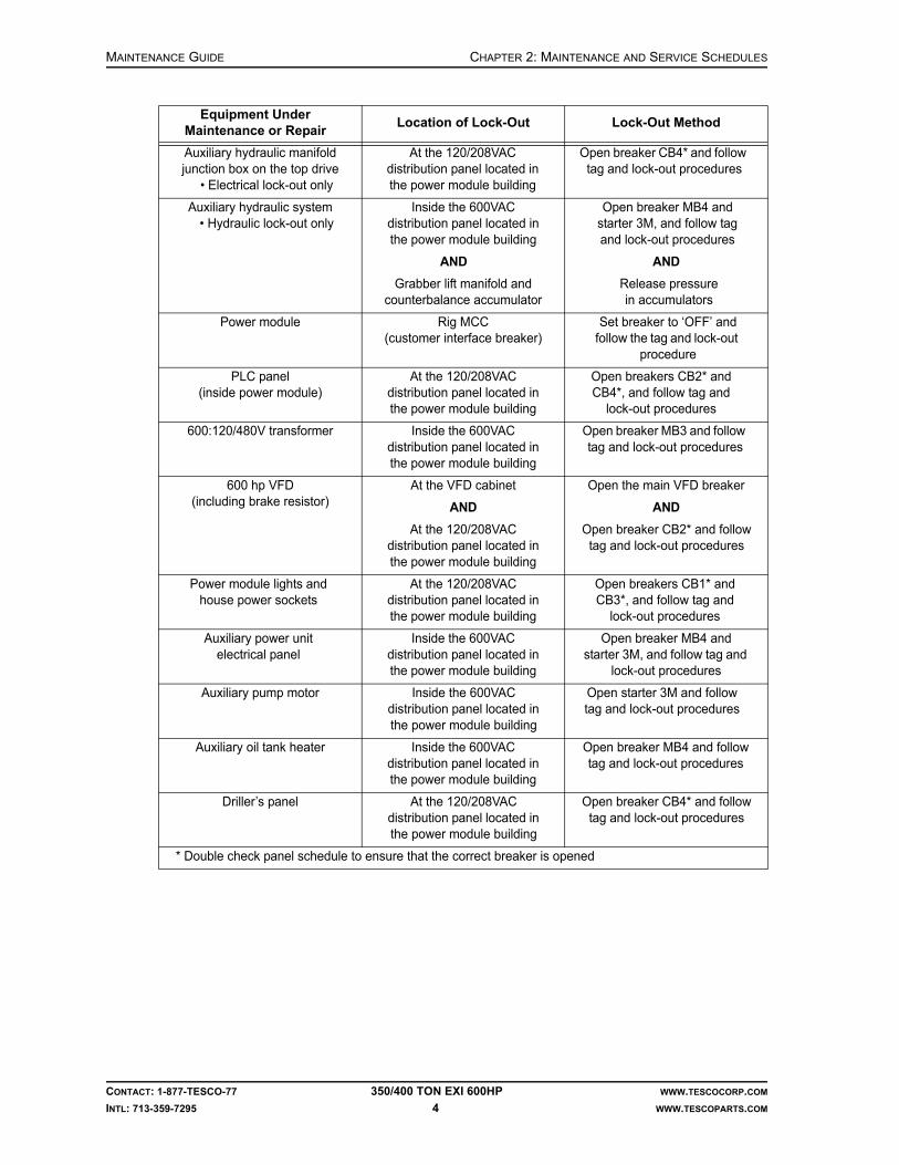
MAINTENANCE GUIDE CHAPTER 2: MAINTENANCE AND SERVICE SCHEDULES
CONTACT: 1-877-TESCO-77 350/400 TON EXI 600HP WWW.TESCOCORP.COM
INTL: 713-359-7295 4 WWW.TESCOPARTS.COM
Auxiliary hydraulic manifold junction box on the top drive
• Electrical lock-out only
At the 120/208VAC distribution panel located in the power module building
Open breaker CB4* and follow tag and lock-out procedures
Auxiliary hydraulic system• Hydraulic lock-out only
Inside the 600VAC distribution panel located in the power module building
AND
Grabber lift manifold and counterbalance accumulator
Open breaker MB4 and starter 3M, and follow tag and lock-out procedures
AND
Release pressure in accumulators
Power module Rig MCC (customer interface breaker)
Set breaker to ‘OFF’ and follow the tag and lock-out
procedure
PLC panel (inside power module)
At the 120/208VAC distribution panel located in the power module building
Open breakers CB2* and CB4*, and follow tag and
lock-out procedures
600:120/480V transformer Inside the 600VAC distribution panel located in the power module building
Open breaker MB3 and follow tag and lock-out procedures
600 hp VFD(including brake resistor)
At the VFD cabinet
AND
At the 120/208VAC distribution panel located in the power module building
Open the main VFD breaker
AND
Open breaker CB2* and follow tag and lock-out procedures
Power module lights and house power sockets
At the 120/208VAC distribution panel located in the power module building
Open breakers CB1* and CB3*, and follow tag and
lock-out procedures
Auxiliary power unit electrical panel
Inside the 600VAC distribution panel located in the power module building
Open breaker MB4 and starter 3M, and follow tag and
lock-out procedures
Auxiliary pump motor Inside the 600VAC distribution panel located in the power module building
Open starter 3M and follow tag and lock-out procedures
Auxiliary oil tank heater Inside the 600VAC distribution panel located in the power module building
Open breaker MB4 and follow tag and lock-out procedures
Driller’s panel At the 120/208VAC distribution panel located in the power module building
Open breaker CB4* and follow tag and lock-out procedures
* Double check panel schedule to ensure that the correct breaker is opened
Equipment Under Maintenance or Repair
Location of Lock-Out Lock-Out Method

CHAPTER 2: MAINTENANCE AND SERVICE SCHEDULES MAINTENANCE GUIDE
CONTACT: 1-877-TESCO-77 350/400 TON EXI 600HP WWW.TESCOCORP.COM
INTL: 713-359-7295 5 WWW.TESCOPARTS.COM
FLUID SPECIFICATION AND CAPACITY SUMMARY
For maintenance and service purposes, occasionally it is necessary to empty and re-fill fluids such as gearbox lubricant and hydraulic oil contained in this top drive system. The list below specifies the type of fluid to use and an approximate volume required for a re-fill.
IMPORTANT: This equipment was filled at the factory with TESCO ULTREX brand fluids and greases. To ensure maximum performance and to avoid cross-contamination, we strongly recommend the continued usage of TESCO ULTREX lubricants, unless otherwise specified.
Note: The volume listed is the amount required to re-fill the particular equipment. If an entire system is drained and serviced, more fluid may be required to fill the system to the specified amount.
TOP DRIVE SERVICE REQUIREMENTS
Daily Top Drive Service
Inspection
Perform the following visual inspection at least once every operating day. More frequent inspections might be required if operating the top drive in harsh or demanding drilling environments.
Table 1: Fluid specification and capacity summary
Equipment description
Fluid details Approx. volumeUS gal (liter)
Notes on fillingTesco prt# Description Data sheet
Top drive gearbox lubricant
731140 Oil,Gear,Semi-Syn, SAE 80W-90
See “ TESCO Ultrex™ Lubricants”
10-1/2 (40) Fill-up to half way up the sight glass
Auxiliary HPU hydraulic fluid
731143 Oil,Trans,Syn,ATF-55, Amsoil
See “ TESCO Ultrex™ Lubricants”
45 (172) To be used in cold climates only
6044 Oil,Hyd,ISO 68 See “ TESCO Ultrex™ Lubricants”
45 (172) To be used in high temperature climates
Inspect For
Gearbox oil level correct gearbox oil level (halfway up sight glass)
Hydraulic hoses and connections at the top drive leaks, damage, excessive wear, hardness, heat cracked or charred; replace if condition occurs
Blower Motor abnormal noise; correct operation

MAINTENANCE GUIDE CHAPTER 2: MAINTENANCE AND SERVICE SCHEDULES
CONTACT: 1-877-TESCO-77 350/400 TON EXI 600HP WWW.TESCOCORP.COM
INTL: 713-359-7295 6 WWW.TESCOPARTS.COM
Lubrication
The following lubrication should be performed at least once every operating day. More fre-quent lubrication might be required if operating the top drive in harsh or demanding drilling environments
IMPORTANT: This equipment was filled at the factory with TESCO ULTREX brand fluids and greases. To ensure maximum performance and to avoid cross-contamination, we strongly recommend the continued usage of TESCO ULTREX lubricants, unless otherwise specified.
Weekly Top Drive Service
The following visual checks should be performed at least once every operating week. More frequent inspection might be required if operating the top drive in harsh or demanding drilling environments.
Lubricate With
Upper quill bearing retainer (1) TESCO ULTREX, NLGI #1 or 2
Lower quill bearing retainer (1) TESCO ULTREX, NLGI #1 or 2
Upper input shaft retainer (1) TESCO ULTREX, NLGI #1 or 2
Lower input shaft retainer (1) TESCO ULTREX, NLGI #1 or 2
Load collar grease port (1) TESCO ULTREX, NLGI #1 or 2
Tilt cylinders (4) TESCO ULTREX, NLGI #1 or 2
Extend cylinders (4) TESCO ULTREX, NLGI #1 or 2
Elevator handle pins (2) TESCO ULTREX, NLGI #1 or 2
Elevator hinge pin (1) TESCO ULTREX, NLGI #1 or 2
Mud valve actuator (1) TESCO ULTREX, NLGI #1 or 2
Pipe handler lock (1) TESCO ULTREX, NLGI #1 or 2
Swivel pins (6) TESCO ULTREX, NLGI #1 or 2
Yoke pins (6) TESCO ULTREX, NLGI #1 or 2
Wash pipe (1) TESCO ULTREX, NLGI #1 or 2
Inspect For
Hydraulic fittings tightness/leaks
Mud saver valve actuator sleeve general condition; disassemble, clean, grease, coat with corrosion inhibitor and reinstall
Counter-balance system cushion height = 2 in.
Motor termination boxes • moisture• tightness of all terminal block screws• tightness of all bus bar bolts• evidence of arcing

CHAPTER 2: MAINTENANCE AND SERVICE SCHEDULES MAINTENANCE GUIDE
CONTACT: 1-877-TESCO-77 350/400 TON EXI 600HP WWW.TESCOCORP.COM
INTL: 713-359-7295 7 WWW.TESCOPARTS.COM
Monthly (Periodic) Top Drive Service
The following visual checks should be performed at least once every operating month or as indicated in the following table. More frequent inspection might be required if operating the top drive in harsh or demanding drilling environments.
Robotics and sensor panels • moisture• tightness of wire terminations
Gearbox lubrication filter • cleanliness• check filter bypass and magnetic plug
Pipe handler rotation motors check for tightness
Load collar springs • damage• breaks
Inspect For
Grabber dies excessive wear
11-station manifold general condition/leaks
Load collar correct spacing between load collar and load nut must be 0.25 in.
Quill end play no end play (see “How to Check for Quill End Play” on page 47)
Main auxiliary hydraulics relief valve correct setting (see “How to Set the Main Pressure Relief Valve for the Auxiliary System” on page 45)
Mud valve (lower ball) manually operate to ensure correct function
All fasteners (nuts, bolts, and lock wires) correct location, tightness
Top drive hydraulic connections and hoses oil leaks/deformation; replace if damaged
Saver sub threads excessive thread wear, seal face condition
Connection locking clamps correct location, tightness
Grabber leg safety chain/shackles broken components/lock wires
Pipe bumper/motor guard dents or bends that may indicate bolt damage
Hammer union on Kelly hose integrity and tightness
Grabber/drawworks and mud valve/mud pump interlocks
function test
Gearbox lubrication system hoses • oil leaks• adequate circulation (pressure 60 to 120 psi when warm)
Gearbox oil analysis abnormalities (take samples to test for water, metal particles, etc); replace every three months as per Table 1 on page 5.
Wash pipe leakage; replace seals if leaking
Top drive electric connectors damage, tightness
Inspect For

MAINTENANCE GUIDE CHAPTER 2: MAINTENANCE AND SERVICE SCHEDULES
CONTACT: 1-877-TESCO-77 350/400 TON EXI 600HP WWW.TESCOCORP.COM
INTL: 713-359-7295 8 WWW.TESCOPARTS.COM
The following lubrication should be performed at least once every operating month. More frequent lubrication might be required if operating the top drive in harsh or demanding drilling environments.
IMPORTANT: This equipment was filled at the factory with TESCO ULTREX brand fluids and greases. To ensure maximum performance and to avoid cross-contamination, we strongly recommend the continued usage of TESCO ULTREX lubricants, unless otherwise specified.
Six-Month Top Drive Service
Lubrication
The following lubrication should be performed at least once every six months. More frequent lubrication might be required if operating the top drive in harsh or demanding drilling environments.
IMPORTANT: This equipment was filled at the factory with TESCO ULTREX brand fluids and greases. To ensure maximum performance and to avoid cross-contamination, we strongly recommend the continued usage of TESCO ULTREX lubricants, unless otherwise specified.
1,000 Operating Day Top Drive Service
Apart from the regular load path and gearbox inspections as defined in Chapter 3: Non-Destructive Testing and Inspection Schedules, the following shall be serviced.
Lubricate With
Hinge pins and extend frame (if applicable) spray with penetrating oil (WD 40, or spray lithium)
Main Motor/Input shaft splines TESCO ULTREX, NLGI #1 or 2
Lubricate With
Main Drive motor bearings TESCO ULTREX, NLGI #1 or 2
Slewing bearing TESCO ULTREX, NLGI #1 or 2
Inspect Action
Hoses replace all auxiliary hydraulic and lubrication system hoses

CHAPTER 2: MAINTENANCE AND SERVICE SCHEDULES MAINTENANCE GUIDE
CONTACT: 1-877-TESCO-77 350/400 TON EXI 600HP WWW.TESCOCORP.COM
INTL: 713-359-7295 9 WWW.TESCOPARTS.COM
Figure 2-1: Lubrication points for the 350T EXI 600 Top Drive

MAINTENANCE GUIDE CHAPTER 2: MAINTENANCE AND SERVICE SCHEDULES
CONTACT: 1-877-TESCO-77 350/400 TON EXI 600HP WWW.TESCOCORP.COM
INTL: 713-359-7295 10 WWW.TESCOPARTS.COM
Figure 2-2: Lubrication points for the 400T EXI 600 Top Drive

CHAPTER 2: MAINTENANCE AND SERVICE SCHEDULES MAINTENANCE GUIDE
CONTACT: 1-877-TESCO-77 350/400 TON EXI 600HP WWW.TESCOCORP.COM
INTL: 713-359-7295 11 WWW.TESCOPARTS.COM
DRILLER’S PANEL SERVICE REQUIREMENTS
Monthly Driller’s Panel Service
The following visual checks should be performed at least once every operating month. More frequent inspection might be required if operating the top drive in harsh or demanding drilling environments.
SERVICE LOOP SERVICE REQUIREMENTS
Weekly Service Loop Service
The following visual checks should be performed at least once every operating week. More frequent inspection might be required if operating the top drive in harsh or demanding drilling environments.
Monthly (Periodic) Service Loop Service
The following visual checks should be performed at least once every operating month. More frequent inspection might be required if operating the top drive in harsh or demanding drilling environments.
Inspect For
Wire terminals in the driller’s panel tightness
Versa max modules locked in place
Indication lights working
Switch contact blocks tightness
Inspect For
All service loop hoses damage, excessive wear, hardness, heat cracked or charred; replace if damaged condition occurs
Urethane capture blocks(at top drive and roller saddle)
hose placement, tightness
Fluid quick couplers (auxiliary hydraulics) damage or decay, tightness
All cable connections and cables(power, sensor, robotics, and ground cables)
damage, tightness and scuffing
Inspect For
All multi-conductor connections moisture, dirt; open and check, then spray with electrical cleaner/moisture dispersant
Main service cable connectors(power, sensor, robotics, ground cables)
cleanliness; open, clean, reinstall

MAINTENANCE GUIDE CHAPTER 2: MAINTENANCE AND SERVICE SCHEDULES
CONTACT: 1-877-TESCO-77 350/400 TON EXI 600HP WWW.TESCOCORP.COM
INTL: 713-359-7295 12 WWW.TESCOPARTS.COM
1,000 Operating Day Service Loop Service
TORQUE ARREST SYSTEM SERVICE REQUIREMENTS
Daily Torque Arrest System Service
The following visual checks should be performed at least once every operating day. More frequent inspection might be required if operating the top drive in harsh or demanding drilling environments.
Weekly Torque Arrest System Service
The following visual checks should be performed at least once every operating week. More frequent inspection might be required if operating the top drive in harsh or demanding drilling environments.
Inspect Action
Hoses replace all hoses
Inspect For
All pinned connections damage or decay/corrosion
All overhead equipment (T-bar, torque beam, torque track, torque bushing)
damage or decay/corrosion
Inspect For
All bolts and threaded rods damage or decay, tightness
Torque track hanging assembly damage; close visual inspection is required
Torque bushing liner wear (the bushing liner must be replaced before the liner mounting bolts come in contact with the torque tube)
Torque bushing clearance amount of clearance (between 1/16” to 1/4”); adjust side plates to obtain clearance as specified
Torque track stabilization components cracks or loose fasteners; close visual inspection is required

CHAPTER 2: MAINTENANCE AND SERVICE SCHEDULES MAINTENANCE GUIDE
CONTACT: 1-877-TESCO-77 350/400 TON EXI 600HP WWW.TESCOCORP.COM
INTL: 713-359-7295 13 WWW.TESCOPARTS.COM
AUXILIARY HYDRAULIC POWER UNIT SERVICE REQUIREMENTS
Daily Auxiliary Hydraulic Power Unit Service
The following visual checks should be performed at least once every operating day. More frequent inspection might be required if operating the top drive in harsh or demanding drilling environments.
IMPORTANT: This equipment was filled at the factory with TESCO ULTREX brand fluids and greases. To ensure maximum performance and to avoid cross-contamination, we strongly recommend the continued usage of TESCO ULTREX lubricants, unless otherwise specified.
Weekly Auxiliary Hydraulic Power Unit Service
The following visual checks should be performed at least once every operating week. More frequent inspection might be required if operating the top drive in harsh or demanding drilling environments.
Monthly (Periodic) Auxiliary Hydraulic Power Unit Service
The following visual checks should be performed at least once every operating month or as indicated in the table below. More frequent inspection might be required if operating the top drive in harsh or demanding drilling environments.
Lubricate With
Hinge pins and extend frame (if applicable) spray with penetrating oil (WD 40, or spray lithium)
Main Motor/Input shaft splines TESCO ULTREX, NLGI #1 or 2
Inspect For
Auxiliary hydraulic oil tank correct oil level
Inspect For
Electric motor and hydraulic pump unnatural noise; pump discoloration that indicates overheating
Inspect For
Hydraulic system pressure relief valve correct setting as per hydraulic schematic (See “How to Set the Secondary Pressure Relief Valve for the Auxiliary System” on page 44.)
Auxiliary system function light pressure switch correct setting (See “How to Set the Function Light Pressure Switch for the Auxiliary System” on page 46.)
Auxiliary hydraulic filter cleanliness; inspect and change if required

MAINTENANCE GUIDE CHAPTER 2: MAINTENANCE AND SERVICE SCHEDULES
CONTACT: 1-877-TESCO-77 350/400 TON EXI 600HP WWW.TESCOCORP.COM
INTL: 713-359-7295 14 WWW.TESCOPARTS.COM
1,000 Operating Day Auxiliary Hydraulic Power Unit Service
POWER MODULE SERVICE REQUIREMENTS
Daily Power Module Service
The following visual checks should be performed at least once every operating day. More frequent inspection might be required if operating the top drive in harsh or demanding drilling environments.
Condensation
Condensation occurs when warm, moist air comes in contact with a cold surface. If the door to the power module is left open, the cool air escapes and warm air enters. This results in conden-sation on and inside the power module cabinets.
Note: If condensation occurs in the power module, do the following:
Auxiliary hydraulic fluid complete fluid analysis; replace every six months or 250 operating days as per Table 1 on page 5
Auxiliary hydraulic hoses leaks, damage, hardness, heat cracked or charred; replace if damaged condition occurs
Inspect Action
Hoses replace all hoses
Inspect For
Drive componentsCaution: Condensation in the drive components can cause severe damage if not immediately addressed. See “Condensation” on page 14.
moisture
VFD for Blower Motor proper operation
Door fans on VFD Cabinets proper operation
Indicator lights on PLC Panel correct function (replace if required)
ESD push button correct function (replace if required)
Braking resistor module for sign of overheating, damage or decay
Inspect For

CHAPTER 2: MAINTENANCE AND SERVICE SCHEDULES MAINTENANCE GUIDE
CONTACT: 1-877-TESCO-77 350/400 TON EXI 600HP WWW.TESCOCORP.COM
INTL: 713-359-7295 15 WWW.TESCOPARTS.COM
1. Ensure the power module building thermostat settings are as follows:
Caution: Keep the power module door closed at all times to help prevent condensation.
Weekly Power Module Service
The following visual checks should be performed at least once every operating week. More frequent inspection might be required if operating the top drive in harsh or demanding drilling environments.
Monthly (Periodic) Power Module Service
The following visual checks should be performed at least once every operating month. More frequent inspection might be required if operating the top drive in harsh or demanding drilling environments.
Warning! Do not perform the following checks unless the main breaker panel is disconnected and locked out.
Warning! Only qualified personnel should perform the following maintenance activities.
User Settings
System Auto
Fan Auto
System Temp 65ºF (18ºC)
Inspect For
Door fans cleanliness, obstructions, restrictions
Ventilation louvers cleanliness, obstructions, restrictions
Inspect For
All wire terminal screws tightness
All bolted connections on both the incoming and outgoing waterfall
tightness
All bolted connections inside 600V panel tightness
VFD input and output power connections tightness
Electrical connections for the main drive components
correct torqueCritical: These connections must be torqued to specification. Severe component damage can result if they are over-tightened. (Refer to Appendix D: “Torque Specification of Electrical Fasteners” on page 75).
!
!
!

MAINTENANCE GUIDE CHAPTER 2: MAINTENANCE AND SERVICE SCHEDULES
CONTACT: 1-877-TESCO-77 350/400 TON EXI 600HP WWW.TESCOCORP.COM
INTL: 713-359-7295 16 WWW.TESCOPARTS.COM
This page has been left blank intentionally.

CHAPTER 3: NON-DESTRUCTIVE TESTING AND INSPECTION SCHEDULES MAINTENANCE GUIDE
CONTACT: 1-877-TESCO-77 350/400 TON EXI 600HP WWW.TESCOCORP.COM
INTL: 713-359-7295 17 WWW.TESCOPARTS.COM
CHAPTER 3: NON-DESTRUCTIVE TESTING AND INSPECTION SCHEDULES
TOP DRIVE OWNER’S GUIDELINES
The integrity, performance, and safe operation of TESCO’s top drives depend on sound maintenance and inspection of all load path, torque arrest system, and critical components. This chapter describes TESCO’s minimum recommended inspection schedule, including the following:
• recommended reporting format for third party inspections• recommended minimum inspection frequency for each load path, torque arrest system
or critical component• specific areas of concern for each component
Caution: In addition to the schedule suggested here, all load path, torque arrest system, and critical components must be inspected following rough drilling, excessive jarring, or any other exceptional circumstance that might increase the likelihood of fatigue failure.
When receiving inspection reports, file them in accordance with procedures in the operating area.
It is critical to maintain complete inspection and service records for all load path, torque arrest system, and other critical components.
Caution: This guide addresses MPI and WFMPI (Wet Fluorescent Magnetic Particle Inspection) testing only. This information must be used in conjunction with a regular inspection and maintenance pro-gram as defined in Chapter 2: Maintenance and Service Schedules.
TESCO will not assume responsibility or liability for any component, product or material that has been repaired, rebuilt, welded, or heat treated outside of TESCO facilities.
!
!

MAINTENANCE GUIDE CHAPTER 3: NON-DESTRUCTIVE TESTING AND INSPECTION SCHEDULES
CONTACT: 1-877-TESCO-77 350/400 TON EXI 600HP WWW.TESCOCORP.COM
INTL: 713-359-7295 18 WWW.TESCOPARTS.COM
GUIDELINES FOR COMPONENT INSPECTORS
Only qualified personnel can inspect load path, torque arrest system, and critical components. Inspectors must use only fully operational, regularly maintained testing equipment. To ensure accurate test results, each component must be thoroughly cleaned before inspection. In some cases removal of paint is required.
If inspecting a TESCO load path, torque arrest system, or critical component, the top drive owner must be provided with the following information.
General information for each component tested:
• type of test or inspection performed (MPI, WFMPI, etc.)• type of equipment used to perform the testing• operating conditions• name and type of inspecting company• name and signature of the inspector• date of inspection
Inspection results for each component tested:
• part description (name, size, etc.)• serial number of the inspected part• exact location of all points of damage (measured from a recognizable point of reference)
including the following:• cracks• excessive wear• deformation• corrosion• erosion
• all dimensions for all cracks (length, depth, width)• a photograph or illustration indicating all cracks or damage points• confirmation that all indicated inspection areas have been checked
LOAD PATH COMPONENTS AND INSPECTION INFORMATION
This chapter contains illustrations of all components in the top drive load path. Each illustra-tion indicates the inspection points for the specific component. It also describes any special considerations that must be addressed when inspecting the component.
It is critical that all components of the load path be subjected to periodic magnetic particle inspection (MPI) by a qualified inspector. Each piece should be inspected for surface defects according to the schedules that follow. MPI inspections shall be done in accordance with API 8C (latest revision).
Note: Any part of an operating day should be considered one day. Removal of paint might be required for inspection.

CHAPTER 3: NON-DESTRUCTIVE TESTING AND INSPECTION SCHEDULES MAINTENANCE GUIDE
CONTACT: 1-877-TESCO-77 350/400 TON EXI 600HP WWW.TESCOCORP.COM
INTL: 713-359-7295 19 WWW.TESCOPARTS.COM
Inspection Types
The three inspection types are outlined in Table 3-1.
Table 3-1: Inspection types
Inspection Type Description
A Visually inspect for:• wear• deformation• cracks• corrosion• galling• heat damage• other irregularities
If a crack is suspected, perform local paint strip and MPI inspection. All cracked components should be referred to TESCO Engineering for disposition.
B Perform MPI or WFMPI for cracks. All cracked components should be referred to TESCO Engineering for disposition.
C Return to a TESCO authorized service center for complete dimensional, visual, WFMPI/MPI inspection for recertification.
Upon completion of Type C inspection, the inspection schedule starts at zero operating days.
Figure 3-1: Yoke and link assembly (350 EXI 600)

MAINTENANCE GUIDE CHAPTER 3: NON-DESTRUCTIVE TESTING AND INSPECTION SCHEDULES
CONTACT: 1-877-TESCO-77 350/400 TON EXI 600HP WWW.TESCOCORP.COM
INTL: 713-359-7295 20 WWW.TESCOPARTS.COM
Figure 3-2: Yoke and Link assembly (400 EXI 600)
Point NameFrequency (Operating Days) and Inspection Type*
At 250 At 500 At 750 At 1000
1 Hook contact point A,B A,B A,B C
2 Swivel yoke A A A C
3 Swivel yoke pin holes A,B A,B A,B C
4 Yoke pins A,B A,B A,B C
5 Swivel links A A A C
6 Swivel link, yoke pin bores A,B A,B A,B C
7 Swivel link, swivel pin bores A,B A,B A,B C
*Refer to Table 3-1 on page 19 for inspection type details
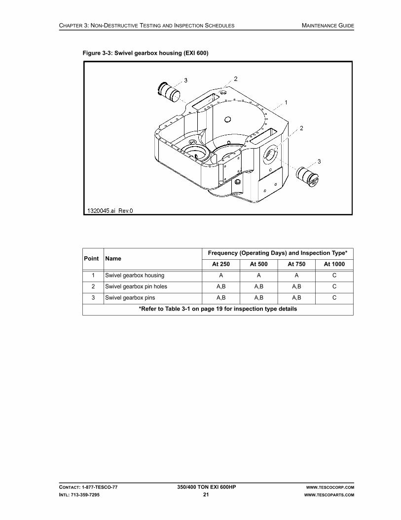
CHAPTER 3: NON-DESTRUCTIVE TESTING AND INSPECTION SCHEDULES MAINTENANCE GUIDE
CONTACT: 1-877-TESCO-77 350/400 TON EXI 600HP WWW.TESCOCORP.COM
INTL: 713-359-7295 21 WWW.TESCOPARTS.COM
Figure 3-3: Swivel gearbox housing (EXI 600)
Point NameFrequency (Operating Days) and Inspection Type*
At 250 At 500 At 750 At 1000
1 Swivel gearbox housing A A A C
2 Swivel gearbox pin holes A,B A,B A,B C
3 Swivel gearbox pins A,B A,B A,B C
*Refer to Table 3-1 on page 19 for inspection type details

MAINTENANCE GUIDE CHAPTER 3: NON-DESTRUCTIVE TESTING AND INSPECTION SCHEDULES
CONTACT: 1-877-TESCO-77 350/400 TON EXI 600HP WWW.TESCOCORP.COM
INTL: 713-359-7295 22 WWW.TESCOPARTS.COM
Figure 3-4: Quill (EXI 600)
Point NameFrequency (Operating Days) and Inspection Type*
Every 60 At 250 At 500 At 750 At 1000
1 Threads on the lower gland nut and bore
— A A A C
2 Upper thrust surface — — — — C
3 Lower thrust surface — — — — C
4 Load nut grooves — A,B A,B A,B C
5 Quill pin end A,B — — — C
*Refer to Table 3-1 on page 19 for inspection type details
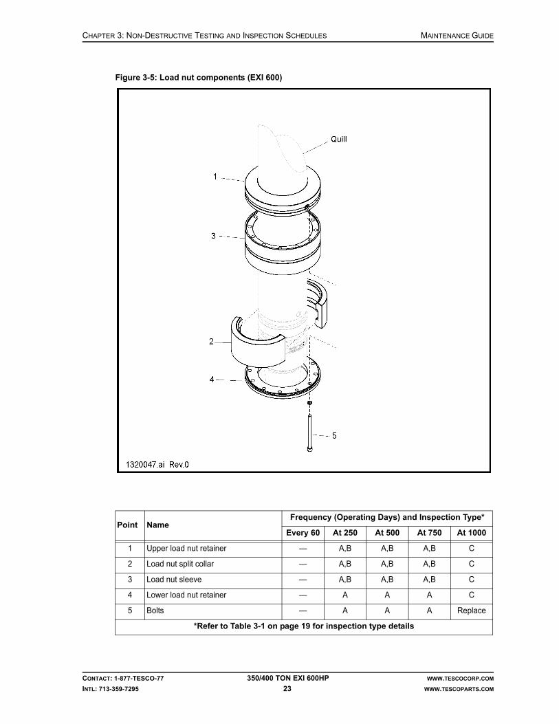
CHAPTER 3: NON-DESTRUCTIVE TESTING AND INSPECTION SCHEDULES MAINTENANCE GUIDE
CONTACT: 1-877-TESCO-77 350/400 TON EXI 600HP WWW.TESCOCORP.COM
INTL: 713-359-7295 23 WWW.TESCOPARTS.COM
Figure 3-5: Load nut components (EXI 600)
Point NameFrequency (Operating Days) and Inspection Type*
Every 60 At 250 At 500 At 750 At 1000
1 Upper load nut retainer — A,B A,B A,B C
2 Load nut split collar — A,B A,B A,B C
3 Load nut sleeve — A,B A,B A,B C
4 Lower load nut retainer — A A A C
5 Bolts — A A A Replace
*Refer to Table 3-1 on page 19 for inspection type details

MAINTENANCE GUIDE CHAPTER 3: NON-DESTRUCTIVE TESTING AND INSPECTION SCHEDULES
CONTACT: 1-877-TESCO-77 350/400 TON EXI 600HP WWW.TESCOCORP.COM
INTL: 713-359-7295 24 WWW.TESCOPARTS.COM
Figure 3-6: Mudsaver valve and actuator (EXI 600)
Point NameFrequency (Operating Days) and Inspection Type*
Every 60 At 250 At 500 At 750 At 1000
1 Top box connection A,B — — — C
2 Upper valve stem hole A,B — — — C
3 Lower valve stem hole A,B — — — C
4 Lower box connection A,B — — — C
5 Length of valve body A,B — — — C
*Refer to Table 3-1 on page 19 for inspection type details

CHAPTER 3: NON-DESTRUCTIVE TESTING AND INSPECTION SCHEDULES MAINTENANCE GUIDE
CONTACT: 1-877-TESCO-77 350/400 TON EXI 600HP WWW.TESCOCORP.COM
INTL: 713-359-7295 25 WWW.TESCOPARTS.COM
Figure 3-7: Saver sub (EXI 600)
Point NameFrequency (Operating Days) and Inspection Type*
Every 60 At 250 At 500 At 750 At 1000
1 Upper seal face A,B — — — C
2 Upper threads A,B — — — C
3 Lower seal face A,B — — — C
4 Lower threads A,B — — — C
5 Entire length of body A,B — — — C
*Refer to Table 3-1 on page 19 for inspection type details

MAINTENANCE GUIDE CHAPTER 3: NON-DESTRUCTIVE TESTING AND INSPECTION SCHEDULES
CONTACT: 1-877-TESCO-77 350/400 TON EXI 600HP WWW.TESCOCORP.COM
INTL: 713-359-7295 26 WWW.TESCOPARTS.COM
Figure 3-8: Load collar (EXI 600)
Point NameFrequency (Operating Days) and Inspection Type*
Every 60 At 250 At 500 At 750 At 1000
1 Load collar ears A A,B A,B A,B C
2 Load nut, load shoulder — A,B A,B A,B C
3 Bronze bushing — — — — C
4 Inner barrel(below the bronze bushing)
— — — — C
*Refer to Table 3-1 on page 19 for inspection type details

CHAPTER 3: NON-DESTRUCTIVE TESTING AND INSPECTION SCHEDULES MAINTENANCE GUIDE
CONTACT: 1-877-TESCO-77 350/400 TON EXI 600HP WWW.TESCOCORP.COM
INTL: 713-359-7295 27 WWW.TESCOPARTS.COM
Figure 3-9: Elevator links (bails) (EXI 600)
Point NameFrequency (Operating Days) and Inspection Type*
Every 250 At 1000
1 Entire length of link A,B** C
2 Top eye (load collar eye) A,B** C
3 Bottom eye (elevator eye) A,B** C
4 Length between the eyes A,B** C
*Refer to Table 3-1 on page 19 for inspection type details**As recommended by the equipment manufacturer

MAINTENANCE GUIDE CHAPTER 3: NON-DESTRUCTIVE TESTING AND INSPECTION SCHEDULES
CONTACT: 1-877-TESCO-77 350/400 TON EXI 600HP WWW.TESCOCORP.COM
INTL: 713-359-7295 28 WWW.TESCOPARTS.COM
Figure 3-10: Elevators (EXI 600)
Point NameFrequency (Operating Days) and Inspection Type*
At 250
1 Main hinge pin C**
2 Primary latch C**
3 Secondary latch C**
4 Elevator link ears C**
5 Elevator body C**
6 Latch pins C**
7 Elevator inserts C**
8 Insert grooves (top and bottom)(Ensure the insert does not fall out)
C**
*Refer to Table 3-1 on page 19 for inspection type details**As recommended by the equipment manufacturer

CHAPTER 3: NON-DESTRUCTIVE TESTING AND INSPECTION SCHEDULES MAINTENANCE GUIDE
CONTACT: 1-877-TESCO-77 350/400 TON EXI 600HP WWW.TESCOCORP.COM
INTL: 713-359-7295 29 WWW.TESCOPARTS.COM
THREADED CONNECTIONS
All threaded connections listed in the following table must be subjected periodically to wet fluorescent magnetic particle inspection (WFMPI) by a qualified inspector. Each piece should be inspected for surface defects. Also, an inspection of threads should be conducted in accordance with the following schedule.
Note: Any part of an operating day should be considered one day.
Caution: All inspections listed in the following table should be performed following any episode of rough drilling, excessive jarring or any other exceptional circumstance that might increase the likelihood of fatigue failure. Operator discretion is critical in determining when this testing should occur.
Threaded Connection Inspection Frequency (EXI 600)
TORQUE ARREST SYSTEM
All components of the torque arrest system must be subjected to periodic magnetic particle inspection (MPI) by a qualified inspector. Each piece should be inspected for surface defects according to the following schedule.
Any part of an operating day should be considered one day. Removal of paint may be required for inspection.
Description Minimum Frequency* Inspection Type
Mud saver/stabbing valve(box X box, connections)
60 operating days WFMPI
Saver sub(pin X pin, connections)
60 operating days(lower threads and seal face require daily visual inspection)
WFMPI
*Frequency = the number of operating days
!

MAINTENANCE GUIDE CHAPTER 3: NON-DESTRUCTIVE TESTING AND INSPECTION SCHEDULES
CONTACT: 1-877-TESCO-77 350/400 TON EXI 600HP WWW.TESCOCORP.COM
INTL: 713-359-7295 30 WWW.TESCOPARTS.COM
Figure 3-11: Non-destructive testing for the standard torque arrest system (EXI 600)

CHAPTER 3: NON-DESTRUCTIVE TESTING AND INSPECTION SCHEDULES MAINTENANCE GUIDE
CONTACT: 1-877-TESCO-77 350/400 TON EXI 600HP WWW.TESCOCORP.COM
INTL: 713-359-7295 31 WWW.TESCOPARTS.COM
Point Name
Frequency (Operating Days) and Inspection Type*
At250
At500
At750
At1000
1 Torque bushing side plates A A A C
2 Torque bushing front plate A A A C
3 Extend frame A A,B A C
4 Redi-rod nuts (torque arrest system) A A A Replace
5 Torque beam clamp bars A A A C
6 Torque track studs/nuts — — — Replace
7 Torque track connectors A A A C
8 Torque track A A A C
9 Torque bushing bolts/nuts — — — Replace
10 Extend arms A A,B A C
11 Torque anchor beam A A A C
12 T-bar clamp plate and bolts A A A C
13 T-bar/torque track bolts A A A Replace
14 T-bar A A,B A C
15 Extend frame mounts A A A C
16 Extend frame bolts A A A Replace
17 Torque track mounting plate on bottom section; include all bolt holes
A A,B A C
T-bar extension (if applicable) A A A C
*Refer to Table 3-1 on page 19 for inspection type details

MAINTENANCE GUIDE CHAPTER 3: NON-DESTRUCTIVE TESTING AND INSPECTION SCHEDULES
CONTACT: 1-877-TESCO-77 350/400 TON EXI 600HP WWW.TESCOCORP.COM
INTL: 713-359-7295 32 WWW.TESCOPARTS.COM
PIPE HANDLER ROTATION SYSTEM INSPECTION FREQUENCY
Figure 3-12: Non-destructive inspection of PH-rotation system components (EXI 600)

CHAPTER 3: NON-DESTRUCTIVE TESTING AND INSPECTION SCHEDULES MAINTENANCE GUIDE
CONTACT: 1-877-TESCO-77 350/400 TON EXI 600HP WWW.TESCOCORP.COM
INTL: 713-359-7295 33 WWW.TESCOPARTS.COM
Point Name
Frequency (Operating Days) and Inspection Type*
Every60
At250
At500
At750
At1000
1 Quill bearing retainer — — — — C
2 Slewing gear teeth — — A — C
3 Slewing gear/gearbox bolts — — — — Replace
4 Pipe handler spool — A A A C
5 Pipe handler spool/slewing drive bolts — — — — Replace
6 Adaptor plate/load collar bolts — — — — C
7 Load collar adaptor plate — — — — C
8 Upper grabber leg mounting bolts — — — — Replace
9 Upper grabber leg — A A A C
10 Grabber mounting bolts — — — — Replace
11 Grabber — A A A C
12 Load collar spring bolts — — — — C
13 Load collar springs — — A — C
14 Pipe handler lock segment — A A,B A C
15 Pipe handler lock body & shim plates — A A A C
16 Pipe handler lock bolts — — — — Replace
17 Rotary union seals — — — — Replace
*Refer to Table 3-1 on page 19 for inspection type details

MAINTENANCE GUIDE CHAPTER 3: NON-DESTRUCTIVE TESTING AND INSPECTION SCHEDULES
CONTACT: 1-877-TESCO-77 350/400 TON EXI 600HP WWW.TESCOCORP.COM
INTL: 713-359-7295 34 WWW.TESCOPARTS.COM
GEARBOX INSPECTION FREQUENCYFigure 3-13: Inspection of gearbox (EXI 600)

CHAPTER 3: NON-DESTRUCTIVE TESTING AND INSPECTION SCHEDULES MAINTENANCE GUIDE
CONTACT: 1-877-TESCO-77 350/400 TON EXI 600HP WWW.TESCOCORP.COM
INTL: 713-359-7295 35 WWW.TESCOPARTS.COM
All load path equipment on the top drive must be inspected at regular intervals. The extent and schedule of these inspections are detailed in this chapter. The most rigorous inspection must take place every 1,000 operating days and include a complete tear down of the top drive. During this 1,000 operating day tear down, the following inspections and replacements must be done on the gearbox components (refer to Figure 3-13 on page 34):
Point NameFrequency (Operating Days) and Inspection Type*
At 250 At 500 At 750 At 1000
1 Upper quill bearing — — — Replace
2 Lower quill bearing — — — Replace
3 Thrust bearing — — — Replace
4 Upper intermediate shaft bearing — — — Replace
5 Lower intermediate shaft bearing — — — Replace
6 Upper input pinion bearing — — — Replace
7 Lower input pinion bearing — — — Replace
8 600hp motor bearings — — — Replace
9 Blower motor bearings — — — Replace
10 Bull gear — — — A,B
11 Intermediate bull gear — — — A,B
12 Intermediate pinion — — — A,B
13 Input pinion — — — A,B
14 Upper quill bearing seals — — — Replace
15 Lower quill bearing seals — — — Replace
16 Upper input pinion seal — — — Replace
17 Lower input pinion seal — — — Replace
18 Mud shield — A — A
19 All O-rings — — — Replace
20 Lubrication hoses A A A Replace
21 Auxiliary hydraulic hoses A A A Replace
*Refer to Table 3-1 on page 19 for inspection type details

MAINTENANCE GUIDE CHAPTER 3: NON-DESTRUCTIVE TESTING AND INSPECTION SCHEDULES
CONTACT: 1-877-TESCO-77 350/400 TON EXI 600HP WWW.TESCOCORP.COM
INTL: 713-359-7295 36 WWW.TESCOPARTS.COM
This page has been left blank intentionally.

CHAPTER 4: SERVICE PROCEDURES MAINTENANCE GUIDE
CONTACT: 1-877-TESCO-77 350/400 TON EXI 600HP WWW.TESCOCORP.COM
INTL: 713-359-7295 37 WWW.TESCOPARTS.COM
CHAPTER 4: SERVICE PROCEDURES
INTRODUCTION
The service procedures described in this chapter are an extension of the service activities discussed in Chapter 2: Maintenance and Service Schedules.

MAINTENANCE GUIDE CHAPTER 4: SERVICE PROCEDURES
CONTACT: 1-877-TESCO-77 350/400 TON EXI 600HP WWW.TESCOCORP.COM
INTL: 713-359-7295 38 WWW.TESCOPARTS.COM
Figure 4-1: General maintenance areas (350 EXI 600)

CHAPTER 4: SERVICE PROCEDURES MAINTENANCE GUIDE
CONTACT: 1-877-TESCO-77 350/400 TON EXI 600HP WWW.TESCOCORP.COM
INTL: 713-359-7295 39 WWW.TESCOPARTS.COM
Figure 4-2: General maintenance areas (400 EXI 600)

MAINTENANCE GUIDE CHAPTER 4: SERVICE PROCEDURES
CONTACT: 1-877-TESCO-77 350/400 TON EXI 600HP WWW.TESCOCORP.COM
INTL: 713-359-7295 40 WWW.TESCOPARTS.COM
HOW TO DISASSEMBLE AND SERVICE THE ROTO-ACTUATOR
This procedure is performed as part of monthly top drive maintenance.
This procedure explains how to clean the internal bore of the actuator and the outer diameter of the mud valve body. If a seal needs to be replaced, or if any other type of service is required, refer to the manufacturer’s service manual.
1. Remove the hydraulic lines for the mud valve-open/valve-close circuit.
2. Plug and cap the hydraulic line terminations to prevent dirt accumulation.
3. Remove the actuator stop bracket.
4. Remove the internal snap rings on the hex drive shaft.
5. Remove the hex drives (2).Note: The strip kit contains a slide hammer for this purpose.
6. Loosen the upper and lower hose clamps.Note: It is easier to loosen them until they can be repositioned above the locator pins than to try to remove them entirely.
7. Loosen all setscrews except 2 by 1/2 turn.Note: Leave two opposing screws tight to hold the actuator in place until it is ready to be removed.
8. Remove the connection-locking clamp for the saver sub.
9. Remove the saver sub.
10. Visually inspect the lower portion of the valve body for raised die marks.Note: Any raised spots will impede the removal of the actuator. Buff them smooth to ensure smooth removal.
11. Place wooden blocks on top of the grabber.Note: These blocks will support the actuator during the next part of this procedure.
12. Raise the grabber to support the weight of the actuator (Refer to “Setting the Grabber Height” in the Operations Guide).
13. Remove all setscrews (8) and springs (8).
14. Remove the locator pins (8) using the slide hammer, if required.Note: The actuator is now separated from the double ball valve.
15. Before continuing, note the orientation of the actuator in relation to the double ball valve.
16. Lower the grabber.
17. Remove the actuator from the double ball valve.Note: The strip kit includes two lifting handles for moving the actuator. These handles screw into any of the locking pin locations.
18. Clean the internal bore of the actuator and the outer diameter of the mud valve body.

CHAPTER 4: SERVICE PROCEDURES MAINTENANCE GUIDE
CONTACT: 1-877-TESCO-77 350/400 TON EXI 600HP WWW.TESCOCORP.COM
INTL: 713-359-7295 41 WWW.TESCOPARTS.COM
Re-assembly
1. Lightly grease the internal bore of the actuator and the outer diameter of the mud valve body.
IMPORTANT: This equipment was filled at the factory with TESCO ULTREX brand fluids and greases. To ensure maximum performance and to avoid cross-contamination, we strongly recommend the continued usage of TESCO ULTREX lubricants, unless otherwise specified.
2. Position the actuator on top of the wooden blocks, on the grabber.
3. Ensure that the actuator and valve are either both open, or both closed.
4. Align the valve sockets on the actuator with the valve sockets on the valve. See Figure 4-3.
Danger! If the orientation is not correct, the valve will not open when required. This causes a serious safety hazard.
5. Slowly raise the grabber to move the actuator to the correct position. The actuator should slide smoothly onto the double ball valve.
6. Install four brass shims between the body of the mud valve and the actuator.Note: The shims help to align the valve and actuator concentrically during assembly.
7. Coat all locking pins and setscrews with a thin coat of anti-seize compound.
Figure 4-3: Actuator/valve orientation
Align the valve sockets before sliding the actuator over the valve.
!

MAINTENANCE GUIDE CHAPTER 4: SERVICE PROCEDURES
CONTACT: 1-877-TESCO-77 350/400 TON EXI 600HP WWW.TESCOCORP.COM
INTL: 713-359-7295 42 WWW.TESCOPARTS.COM
8. Install the locking pins, springs and setscrews as follows:
a. Put all locking pins, spring and setscrews in place.
b. Turn the setscrews until they meet the springs, but do not tighten them.
c. Start the locking pins.
9. Install the hex drives (2).
10. Install the snap rings into snap ring grooves.
11. Tighten all setscrews, evenly, to 100 ft-lb (136 N-m).
12. Install a hose clamp over the locking pins.
13. Remove the brass centering shims.
14. Lower the grabber.
15. Remove the wooden blocks.
16. Rotate the quill with the top drive to position the locking mechanism to accept the stop bracket of the actuator.
17. Install the stop bracket.
18. Connect the hydraulic lines for the mud valve-open/valve-close circuit.
19. Test the actuator to confirm that it is working correctly.
HOW TO SET THE COUNTER-BALANCE CUSHION HEIGHT
The following conditions must exist before the following portion of the counter-balance installation can be completed.
• The top drive must be installed.• The hydraulic circuit must be connected.• The driller’s panel must be operational.• The top drive must be positioned at the racking platform.
1. Connect the hose quick-coupler for the elevator to the charge fitting for the counter-balance system.
2. Shut off the auxiliary pump.
3. Open the needle valve on the counter-balance charge hose.
4. Set the ELEVATOR switch (at the driller’s panel) to ‘OPEN’, push and hold the ELEVATOR SAFETY–OPEN button.
Note: This allows the hydraulic fluid to drain from the counter balance circuit.
5. Check the nitrogen pressure, and adjust to 1,200 psi (8.3 MPa) if required.
6. Ensure the counter-balance relief valve is set at 1,800 psi (12.4 MPa).Note: The relief valve on the CE/ATEX certified units are preset and cannot be adjusted.
7. Close the needle valve on the counter-balance charge hose
8. Start the auxiliary pump.
9. Set the ELEVATOR switch (driller’s panel) to ‘CLOSE’.Note: This will send 1,500 psi (10.3 MPa) hydraulic pressure to the needle valve on the counter-balance manifold.

CHAPTER 4: SERVICE PROCEDURES MAINTENANCE GUIDE
CONTACT: 1-877-TESCO-77 350/400 TON EXI 600HP WWW.TESCOCORP.COM
INTL: 713-359-7295 43 WWW.TESCOPARTS.COM
10. Slowly open the needle valve and allow the hydraulic oil to charge the counter-balance system.
11. Monitor the counter-balance cushion by watching the gap that develops between the yoke pin and the top of the swivel link bore, refer to Figure 4-4 on page 43.
12. Continue to charge the system until the gap is 1-1/2 in. to 2 in.
13. Close the needle valve.
14. Shut off the auxiliary pump.Note: This will allow the oil pressure in the auxiliary system to decrease.
15. Set the ELEVATOR switch to ‘OPEN’, then to ‘CLOSE’. This will relieve any pressure in the system.
16. Remove the elevator hydraulic hose from the counter-balance manifold.
Caution: If disconnecting a quick coupler while there is pressure in the system, it will be extremely difficult to reconnect the coupler.
Figure 4-4: Counter-balance cushion height (350 EXI 600)
!

MAINTENANCE GUIDE CHAPTER 4: SERVICE PROCEDURES
CONTACT: 1-877-TESCO-77 350/400 TON EXI 600HP WWW.TESCOCORP.COM
INTL: 713-359-7295 44 WWW.TESCOPARTS.COM
HOW TO SET THE SECONDARY PRESSURE RELIEF VALVE FOR THE AUXILIARY SYSTEM
The main pressure relief valve is located on the 10-station manifold of the top drive. However, a secondary relief valve is located on the auxiliary power unit. The secondary relief valve must be set first. It must be set 200 psi higher than the main pressure relief valve. Follow the proce-dure described below to set the secondary pressure relief valves.
1. Disconnect the auxiliary hydraulic service loop from the power unit or at the top drive.
2. Loosen the lock nut on the relief valve at the power unit and back out the adjustment screw to the maximum.
3. Start the auxiliary pump by setting the AUX PUMP switch (at the driller’s panel) to ‘ON’.
4. The hydraulic oil will now flow over the relief valve.
5. Slowly turn the adjustment screw until the pressure gauge on the power unit indicates the desired pressure (it should be 200 psi (1.4 MPa) higher than the value the main pressure relief valve needs to be set to).
6. Set the AUX PUMP switch to ‘OFF’.
7. Tighten the lock nut on the relief valve.
8. Switch on the auxiliary pump and confirm the pressure setting on the pressure gauge.
Figure 4-5: Counter-balance cushion height (400 EXI 600)

CHAPTER 4: SERVICE PROCEDURES MAINTENANCE GUIDE
CONTACT: 1-877-TESCO-77 350/400 TON EXI 600HP WWW.TESCOCORP.COM
INTL: 713-359-7295 45 WWW.TESCOPARTS.COM
9. Switch off the auxiliary pump and open the bypass valve to relieve the pressure; refer to Figure 4-7 on page 46.
10. Connect the auxiliary hydraulic service loop.
11. The secondary relief valve is now set.
HOW TO SET THE MAIN PRESSURE RELIEF VALVE FOR THE AUXILIARY SYSTEM
The main pressure relief valve is located on the 10-station manifold of the top drive. Follow the procedure described below to set the main pressure relief valve.
Note: This procedure applies only to standard CSA units. It does not apply to the CE/ATEX certified units because the main pressure relief valve on the CE/ATEX certified units are preset and cannot be adjusted.
Note: Before the main pressure relief valve is set, ensure the secondary pressure relief valve (located on the auxiliary power unit) is set as per the procedure described in the previous section “How to Set the Secondary Pressure Relief Valve for the Auxiliary System” on page 44.
Figure 4-6: Auxiliary system main pressure relief valve
1. Locate the main pressure relief valve on the top drive (see “Figure 4-6: Auxiliary system main pressure relief valve”).
2. Loosen the lock nut on the main relief valve adjustment screw and back out the adjustment screw to its maximum.

MAINTENANCE GUIDE CHAPTER 4: SERVICE PROCEDURES
CONTACT: 1-877-TESCO-77 350/400 TON EXI 600HP WWW.TESCOCORP.COM
INTL: 713-359-7295 46 WWW.TESCOPARTS.COM
3. Start the auxiliary pump by setting the AUX PUMP switch (at the driller’s panel) to ‘ON’.
4. Set the PIPE HANDLER LOCK switch to ‘LOCK’. The auxiliary hydraulic system is now dead headed and the hydraulic oil will flow over the main relief valve.
5. Slowly turn the adjustment screw on the relief valve until the auxiliary pressure gauge on the top drive indicates the desired pressure (the desired pressure setting of the relief valve is listed on the applicable hydraulic schematic drawing).
6. Tighten the lock nut.
7. Set the PIPE HANDLER LOCK switch to neutral.
8. After a few seconds, set the PIPE HANDLER LOCK switch again to ‘LOCK’.
9. Confirm the pressure setting on the pressure gauge.
10. Set the PIPE HANDLER LOCK switch to neutral.
11. Set the AUX PUMP switch to ‘OFF’.
12. The main relief valve is now set.
HOW TO SET THE FUNCTION LIGHT PRESSURE SWITCH FOR THE AUXILIARY SYSTEM
Perform this procedure as part of the monthly auxiliary hydraulic power unit maintenance.
Note: The function light pressure switch for the auxiliary system should be set to 800 psi (5.5 MPa). It is easier if two people perform this procedure.
1. Ensure the auxiliary pump is shut off.
2. Disconnect the pressure line to the top drive.Note: The quick coupler is located at the auxiliary hydraulic power unit.
3. Open the bypass ball valve for the auxiliary system.Note: This ball valve is located between the pressure line and the return quick-couplers at the auxiliary hydraulic power unit.
Figure 4-7: Auxiliary hydraulic system schematic
1. Quick coupler2. Return auxiliary hydraulic line3. By-pass ball valve4. Supply auxiliary hydraulic line5. Oil reservoir

CHAPTER 4: SERVICE PROCEDURES MAINTENANCE GUIDE
CONTACT: 1-877-TESCO-77 350/400 TON EXI 600HP WWW.TESCOCORP.COM
INTL: 713-359-7295 47 WWW.TESCOPARTS.COM
4. Set the AUX PUMP switch to ‘ON’.
5. Slowly close the ball valve to raise the pressure to 700 psi (4.8 MPa).Note: Pressure is indicated on the adjacent pressure gauge.
6. Use the adjustment wheel on the pressure switch to adjust the pressure until the AUX PUMP ‘ON’ indicator light on the driller’s panel illuminates.
Note: Someone might need to stand at the driller’s panel to monitor the light. If no assistance is available, use a digital multi-meter as follows:
a. Attach the black lead to terminal PSP-1 (wire #2) and the red lead to the output side of the pressure switch, terminal PSP-3 (wire #407).
b. Adjust the pressure switch.
c. When the meter rises to 24V nominal, the indicator light is illuminated.
7. Set the AUX PUMP switch to ‘OFF’.
8. Reconnect the pressure line to the top drive.
9. Close the bypass ball valve for the auxiliary system.
10. Operate any hydraulic function to confirm that the indicator light is operating correctly.
HOW TO CHECK AND ADJUST PRELOAD FOR THE QUILL UPPER BEARING
When the top drive is manufactured, TESCO adjusts the preload for the quill upper bearing by placing a shim pack between the top bearing retainer and the gearbox.
When the retainer bolts on the top bearing are torqued, this exerts a clamping force on the quill upper bearing and thrust bearing. This force prevents the quill from exhibiting end play during operation of the top drive. Preload is measured in 0.000 of an inch. The ideal preload is 0.005 to 0.007 in.
Over time, bearing and component wear will reduce the preload. If the preload is reduced too much, quill end play will result. Even the smallest amount of end play will result in damage to the bearings and mating components.
For this reason, quill end play should be checked every month, or after any severe operating events such as jarring or rough drilling.
How to Check for Quill End Play
1. Remove the washpipe.
2. Install a heavy wooden block across the grabber box.
3. Attach the magnetic base of a dial gauge to the top surface of the quill.
4. Position the dial needle on the bearing retainer.
5. Set the dial gauge to zero.
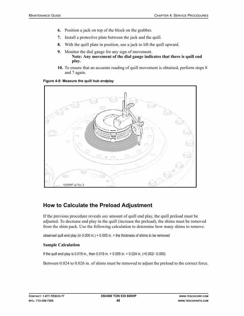
MAINTENANCE GUIDE CHAPTER 4: SERVICE PROCEDURES
CONTACT: 1-877-TESCO-77 350/400 TON EXI 600HP WWW.TESCOCORP.COM
INTL: 713-359-7295 48 WWW.TESCOPARTS.COM
6. Position a jack on top of the block on the grabber.
7. Install a protective plate between the jack and the quill.
8. With the quill plate in position, use a jack to lift the quill upward.
9. Monitor the dial gauge for any sign of movement.Note: Any movement of the dial gauge indicates that there is quill end play.
10. To ensure that an accurate reading of quill movement is obtained, perform steps 8 and 7 again.
How to Calculate the Preload Adjustment
If the previous procedure reveals any amount of quill end play, the quill preload must be adjusted. To decrease end play in the quill (increase the preload), the shims must be removed from the shim pack. Use the following calculation to determine how many shims to remove.
observed quill end play (in 0.000 in.) + 0.005 in. = the thickness of shims to be removed
Sample Calculation
If the quill end play is 0.019 in., then 0.019 in. + 0.005 in. = 0.024 in. (+0.002/ -0.000)
Between 0.024 to 0.026 in. of shims must be removed to adjust the preload to the correct force.
Figure 4-8: Measure the quill hub endplay

CHAPTER 4: SERVICE PROCEDURES MAINTENANCE GUIDE
CONTACT: 1-877-TESCO-77 350/400 TON EXI 600HP WWW.TESCOCORP.COM
INTL: 713-359-7295 49 WWW.TESCOPARTS.COM
How to Adjust the Preload
It is important to keep all components clean and free of grit and debris. Ensure that the working area is clean before performing this procedure.
1. Remove the washpipe and bonnet.
2. Remove all upper bearing retainer bolts.
3. Thread two long 5/8”-11 UNC bolts into the retainer bolt holes (these are used as alignment pins).
4. Install three lifting eyes into threaded holes.
5. Using a chain fall or other lifting device, remove the quill retainer to allow access to the shim pack.
6. Remove the required shims from the shim pack.Note: Shim packs typically contain 0.010 in., 0.005 in., and 0.002 in. shims. Remove the shims to achieve a preload of 0.005 to 0.007 in. If required, shims are available from TESCO.
7. Use a chain fall or other lifting device to lower the bearing retainer back into position.
8. Remove the alignment pins.
9. Replace all upper bearing retainer bolts.Note: To check preload again, replace every second retainer bolt and retest according the procedure “How to Check for Quill End Play” on page 47.
Figure 4-9: Preload adjustment

MAINTENANCE GUIDE CHAPTER 4: SERVICE PROCEDURES
CONTACT: 1-877-TESCO-77 350/400 TON EXI 600HP WWW.TESCOCORP.COM
INTL: 713-359-7295 50 WWW.TESCOPARTS.COM
This page has been left blank intentionally.

CHAPTER 5: DISASSEMBLY AND ASSEMBLY INSTRUCTIONS MAINTENANCE GUIDE
CONTACT: 1-877-TESCO-77 350/400 TON EXI 600HP WWW.TESCOCORP.COM
INTL: 713-359-7295 51 WWW.TESCOPARTS.COM
CHAPTER 5: DISASSEMBLY AND ASSEMBLY INSTRUCTIONS
Install the Mudsaver Valve
1. Apply pipe dope to the mudsaver valve and quill pin.
2. Lift the mudsaver valve and place it on the grabber.
Caution: The bottom of the valve will extend through the grabber box. Do not close the grabber.
Note: The valve actuator can be put on blocks. This will raise the valve actua-tor so that it can easily connect to the quill.
3. At the driller’s panel, set the MODE switch to ‘DRILL’, and set the QUILL switch to ‘FWD’.
4. Set the TORQUE value to approximately 5,500 ft-lb/7,458 N-m (10% of the make up torque for an NC61 connection). Set the SPEED value to 5 rpm.
Note: DRILL mode allows precise control of rotation and is the safest operating mode for this procedure.
5. Slowly raise the grabber until the quill connects with the mudsaver valve.
Caution: Hold the valve by hand to start the connection.
Figure 5-1: How to use blocks to raise the mudsaver valve
!
!

MAINTENANCE GUIDE CHAPTER 5: DISASSEMBLY AND ASSEMBLY INSTRUCTIONS
CONTACT: 1-877-TESCO-77 350/400 TON EXI 600HP WWW.TESCOCORP.COM
INTL: 713-359-7295 52 WWW.TESCOPARTS.COM
Danger! Exercise extreme caution. Do not become entangled in moving equipment.
6. Screw the quill/mudsaver connection together by hand.
Caution: Do not use the top drive to make the connection; this can damage the valve threads.
7. Lower the grabber and remove the wooden blocks (if applicable).
8. Raise the grabber so that it will close on the mudsaver valve.
9. Set the GRABBER switch to ‘CLOSE’; close the grabber on the mudsaver valve.
10. At the driller’s panel, set the MODE switch to ‘CONN’. Set the QUILL switch to ‘FWD’.
11. Increase the torque setting to the required make up torque value for an NC61 con-nection (make up torque for NC61 = 55,600 ft-lb/75,393 N-m).
12. Set the QUILL switch to neutral when the desired torque is achieved.
13. Open and lower the grabber.
14. Place the die lock clamp on top of the mud saver valve actuator.
15. Apply anti-seize compound to all the lock bolts (8) and install them loosely.
16. Raise the die lock clamp into position and hold.Note: Position the clamp so it evenly straddles the connection between the quill and mud saver valve.
17. Tighten the cap screws evenly.Note: Monitor the end gaps to ensure that the clamp is installed evenly.
18. Torque the bolts to 550 ft-lb (746 N-m).
19. Seat the dies by striking the back side of each half of the clamp as hard as possible with a sledge hammer.
20. When the dies seat properly, torque all bolts again to 550 ft-lb (746 N-m).
!
!

CHAPTER 5: DISASSEMBLY AND ASSEMBLY INSTRUCTIONS MAINTENANCE GUIDE
CONTACT: 1-877-TESCO-77 350/400 TON EXI 600HP WWW.TESCOCORP.COM
INTL: 713-359-7295 53 WWW.TESCOPARTS.COM
HOW TO DISASSEMBLE AND ASSEMBLE THE GRABBER
IMPORTANT: This equipment was filled at the factory with TESCO ULTREX brand fluids and greases. To ensure maximum performance and to avoid cross-contamination, we strongly recommend the continued usage of TESCO ULTREX lubricants, unless otherwise specified.
Introduction
This section contains the procedures that explain how to disassemble and assemble the grabber components:
• How to Change the Grabber Dies• How to Remove, Service, and Reinstall the Grabber Actuating Piston• How to Remove and Reinstall the Grabber Leg
The grabber might require disassembly and repair if the following problems occur:
• The grabber will not open or close even though electrical and hydraulic circuits are oper-ating normally.
• The grabber will not hold the required pressure.• A hydraulic oil leak is detected.
How to Change the Grabber Dies
It is easiest to perform this procedure if the drill pipe is disconnected and the saver sub is removed, however, grabber dies can be changed with the drill pipe connected to the saver sub, if required.
Caution: This procedure requires the removal and replacement of small parts. If possible, use the EXTEND function to move the bot-tom of the grabber away from hole center. Cover all exposed areas around well center to prevent parts from falling through the table.
Caution: It is easier to access the grabber dies and bolts if the grabber is partially closed. Do not allow the grabber to close fully.
1. At the driller’s panel, set the AUXILIARY PUMP switch to ‘ON’.
2. Select Grabber OPEN/CLOSE switch to ‘OPEN’.
3. Set Grabber OPEN/CLOSE switch to neutral and switch auxiliary pump off.
Caution: Use current lock-out procedures to lock out the auxiliary pump.
4. Remove the keeper plates (2) on the lower die and the retaining bolts (2 per plate).
5. Use a long pin punch or similar tool to tap the dies downward and out of the die holder blocks.
6. Remove spacers, if used.
!
!
!
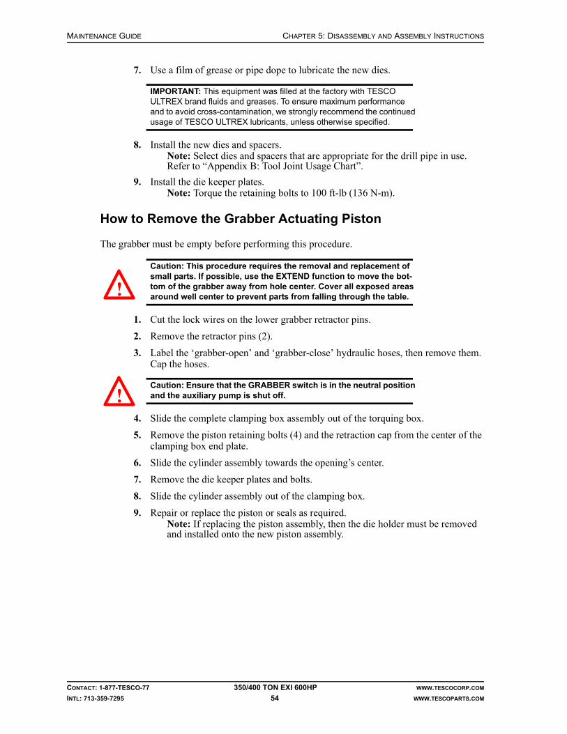
MAINTENANCE GUIDE CHAPTER 5: DISASSEMBLY AND ASSEMBLY INSTRUCTIONS
CONTACT: 1-877-TESCO-77 350/400 TON EXI 600HP WWW.TESCOCORP.COM
INTL: 713-359-7295 54 WWW.TESCOPARTS.COM
7. Use a film of grease or pipe dope to lubricate the new dies.
IMPORTANT: This equipment was filled at the factory with TESCO ULTREX brand fluids and greases. To ensure maximum performance and to avoid cross-contamination, we strongly recommend the continued usage of TESCO ULTREX lubricants, unless otherwise specified.
8. Install the new dies and spacers.Note: Select dies and spacers that are appropriate for the drill pipe in use. Refer to “Appendix B: Tool Joint Usage Chart”.
9. Install the die keeper plates.Note: Torque the retaining bolts to 100 ft-lb (136 N-m).
How to Remove the Grabber Actuating Piston
The grabber must be empty before performing this procedure.
Caution: This procedure requires the removal and replacement of small parts. If possible, use the EXTEND function to move the bot-tom of the grabber away from hole center. Cover all exposed areas around well center to prevent parts from falling through the table.
1. Cut the lock wires on the lower grabber retractor pins.
2. Remove the retractor pins (2).
3. Label the ‘grabber-open’ and ‘grabber-close’ hydraulic hoses, then remove them. Cap the hoses.
Caution: Ensure that the GRABBER switch is in the neutral position and the auxiliary pump is shut off.
4. Slide the complete clamping box assembly out of the torquing box.
5. Remove the piston retaining bolts (4) and the retraction cap from the center of the clamping box end plate.
6. Slide the cylinder assembly towards the opening’s center.
7. Remove the die keeper plates and bolts.
8. Slide the cylinder assembly out of the clamping box.
9. Repair or replace the piston or seals as required.Note: If replacing the piston assembly, then the die holder must be removed and installed onto the new piston assembly.
!
!

CHAPTER 5: DISASSEMBLY AND ASSEMBLY INSTRUCTIONS MAINTENANCE GUIDE
CONTACT: 1-877-TESCO-77 350/400 TON EXI 600HP WWW.TESCOCORP.COM
INTL: 713-359-7295 55 WWW.TESCOPARTS.COM
Figure 5-2: Grabber box components

MAINTENANCE GUIDE CHAPTER 5: DISASSEMBLY AND ASSEMBLY INSTRUCTIONS
CONTACT: 1-877-TESCO-77 350/400 TON EXI 600HP WWW.TESCOCORP.COM
INTL: 713-359-7295 56 WWW.TESCOPARTS.COM
How to Reinstall the Grabber Actuating Piston
The following procedure assumes that all grabber cylinder components are assembled.
1. Install the die holder plate on the end of the grabber cylinder.
2. Torque the retainer plate bolts to 100 ft-lb (136 N-m).
3. Slide the cylinder assembly into the clamping box.Note: Ensure that the port extensions are oriented upward.
4. Install the port extensions (2).
5. Install the retraction cap and piston retaining bolts (4), and torque the bolts to 100 ft-lb (136 N-m).
6. Invert the clamping box.Note: Place the clamping box on wooden blocks to protect port extensions.
7. Install the dies, keeper plates, and die keeper bolts.
8. Secure all drilled bolts in place with lockwire.
9. Slide the clamping box into the outer torquing box.
10. Install the retraction pins (2) and secure them in place with lock wire.
11. Connect the grabber open/close hydraulic lines.
How to Repair the Grabber Cylinder
This procedure assumes that the grabber cylinder has been removed from the clamping box. Refer to “Appendix B: Tool Joint Usage Chart” to determine which dies and spacers to use for the tool joint in use.
1. Remove the port extensions (2) from the top of the cylinder assembly.
2. Use the gland nut spanner supplied by TESCO to remove the brass gland nut from the end of the cylinder.
3. Pull the piston out of the cylinder.
4. Replace the seals and inspect the cylinder for internal damage.Note: Use a fine emery cloth or a fine grit cylinder hone to remove small surface defects.
5. Install new gland seals as required.
Caution: Exercise caution when reassembling this component. The piston open/close ports can damage the gland seals.
6. Assemble the piston components.Note: Ensure that all bolts and O-rings are coated with light grease before assembly.
7. Actuate the cylinder with oil to purge the air from the cylinder.
Danger! Air in the cylinder will act as an accumulator. Accumulation of pressure can cause injury when the piston is tested.
8. Pressure-test the piston assembly to 2,000 psi on both the open and close side of the circuit.
!
!

CHAPTER 5: DISASSEMBLY AND ASSEMBLY INSTRUCTIONS MAINTENANCE GUIDE
CONTACT: 1-877-TESCO-77 350/400 TON EXI 600HP WWW.TESCOCORP.COM
INTL: 713-359-7295 57 WWW.TESCOPARTS.COM
How to Remove and Reinstall the Grabber Leg
Figure 5-3: Grabber leg assembly
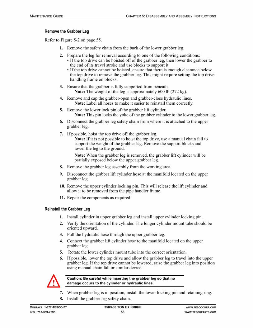
MAINTENANCE GUIDE CHAPTER 5: DISASSEMBLY AND ASSEMBLY INSTRUCTIONS
CONTACT: 1-877-TESCO-77 350/400 TON EXI 600HP WWW.TESCOCORP.COM
INTL: 713-359-7295 58 WWW.TESCOPARTS.COM
Remove the Grabber Leg
Refer to Figure 5-2 on page 55.
1. Remove the safety chain from the back of the lower grabber leg.
2. Prepare the leg for removal according to one of the following conditions:• If the top drive can be hoisted off of the grabber leg, then lower the grabber to
the end of its travel stroke and use blocks to support it.• If the top drive cannot be hoisted, ensure that there is enough clearance below
the top drive to remove the grabber leg. This might require setting the top drive handling frame on blocks.
3. Ensure that the grabber is fully supported from beneath.Note: The weight of the leg is approximately 600 lb (272 kg).
4. Remove and cap the grabber-open and grabber-close hydraulic lines.Note: Label all hoses to make it easier to reinstall them correctly.
5. Remove the lower lock pin of the grabber lift cylinder.Note: This pin locks the yoke of the grabber cylinder to the lower grabber leg.
6. Disconnect the grabber leg safety chain from where it is attached to the upper grabber leg.
7. If possible, hoist the top drive off the grabber leg.Note: If it is not possible to hoist the top drive, use a manual chain fall to support the weight of the grabber leg. Remove the support blocks and lower the leg to the ground.
Note: When the grabber leg is removed, the grabber lift cylinder will be partially exposed below the upper grabber leg.
8. Remove the grabber leg assembly from the working area.
9. Disconnect the grabber lift cylinder hose at the manifold located on the upper grabber leg.
10. Remove the upper cylinder locking pin. This will release the lift cylinder and allow it to be removed from the pipe handler frame.
11. Repair the components as required.
Reinstall the Grabber Leg
1. Install cylinder in upper grabber leg and install upper cylinder locking pin.
2. Verify the orientation of the cylinder. The longer cylinder mount tube should be oriented upward.
3. Pull the hydraulic hose through the upper grabber leg.
4. Connect the grabber lift cylinder hose to the manifold located on the upper grabber leg.
5. Rotate the lower cylinder mount tube into the correct orientation.6. If possible, lower the top drive and allow the grabber leg to travel into the upper
grabber leg. If the top drive cannot be lowered, raise the grabber leg into position using manual chain fall or similar device.
Caution: Be careful while inserting the grabber leg so that no damage occurs to the cylinder or hydraulic lines.
7. When grabber leg is in position, install the lower locking pin and retaining ring.8. Install the grabber leg safety chain.
!

CHAPTER 6: LONG TERM PRESERVATION AND STORAGE MAINTENANCE GUIDE
CONTACT: 1-877-TESCO-77 350/400 TON EXI 600HP WWW.TESCOCORP.COM
INTL: 713-359-7295 59 WWW.TESCOPARTS.COM
CHAPTER 6: LONG TERM PRESERVATION AND STORAGE
INTRODUCTION
Use the following guidelines whenever a TESCO top drive is placed into long term storage.
Before beginning these procedures, ensure that all necessary unit maintenance is complete and the unit is fully functional.
If all repairs cannot be completed, ensure that the following is created:
• a detailed list of maintenance/repair requirements• a complete list of parts required
BEFORE SYSTEM SHUT DOWN
Before shutting down the top drive system, do the following:
1. Add corrosion inhibitor to the gearbox. Most oil inhibitors require some mixing with the base oil. Prepare the corrosion inhibitor according to the manufacturer’s instruction.
2. Determine if a load path inspection needs to be performed before re-starting the unit. If an inspection will be required, ensure that all load path connections are broken out now. This will allow the top drive system to be inspected without having to supply power to the unit.
The following procedures assume that the top drive system has already been correctly decommissioned as described in the Rig Out Procedures section of the Installation Guide for the unit.
MAINTENANCE GUIDE CHAPTER 6: LONG TERM PRESERVATION AND STORAGE
CONTACT: 1-877-TESCO-77 350/400 TON EXI 600HP WWW.TESCOCORP.COM
INTL: 713-359-7295 60 WWW.TESCOPARTS.COM
TOP DRIVE
IMPORTANT: This equipment was filled at the factory with TESCO ULTREX brand fluids and greases. To ensure maximum performance and to avoid cross-contamination, we strongly recommend the continued usage of TESCO ULTREX lubricants, unless otherwise specified.
Junction Boxes
Motor Termination Junction Boxes
1. Open all motor termination junction boxes.
2. Check for moisture.
3. Verify that all connections are torqued to specification (see “Appendix D: Torque Specification of Electrical Fasteners”).
4. Close and reseal the junction box.
Top Drive Junction Box
1. Open the motor sensor junction box.
2. Check for moisture.
3. Install a new desiccant pack.
4. Tighten all wire terminals in the junction box.
5. Close and reseal the junction box.
When these procedures are complete, seal all junction boxes with corrosion inhibitor tape. Also, ensure that all breather openings are sealed.
Quill
1. Clean and inspect the quill connections.Note: The mudsaver valve must be removed before the lower connection can be inspected.
2. Coat all connections with thread compound or preservative grease.
3. Wrap all connections with corrosion inhibitor tape.
Load Nut (where applicable)
Remove the load nut and service it as follows:
1. Clean and inspect all parts of the load nut.
2. Coat all segments with light oil, then reinstall.
3. Apply a coat of grease to the outside of the load nut, particularly the load shoulder.

CHAPTER 6: LONG TERM PRESERVATION AND STORAGE MAINTENANCE GUIDE
CONTACT: 1-877-TESCO-77 350/400 TON EXI 600HP WWW.TESCOCORP.COM
INTL: 713-359-7295 61 WWW.TESCOPARTS.COM
Grabber Leg
1. Remove the grabber leg.
2. Apply a liberal coat of grease to the sliding section of the lower leg.
3. Grease the exposed sections of the cylinder rods on the grabber leg.
4. Apply grease or anti-seize compound to all pin pockets and threads.
5. Reinstall the grabber leg.
6. Remove the clamping box from the grabber torque box.
7. Remove the grabber cylinder from the clamping box.
8. Remove the die holder plates and dies.
9. Inspect and clean all die holder plates and dies.
10. Apply grease or anti-seize compound to all die holder plates and dies.
11. Reassemble the grabber components.
12. Coat the entire torque box with a light film of grease.
13. Install the grabber cylinder and clamping box in the torque box.
Pipe Handler
1. Clean the slewing gear and coat with a lighter film of grease.
2. Grease all grease nipples on the slewing gear.
3. Grease the ends of all link tilt cylinders.
4. Fully retract all link tilt cylinders (the cylinders should be disconnected from the elevator links).
5. Grease the load collar.
Hydraulics
1. Disconnect all quick connections and clean with suitable contact cleaner.
2. Wrap each quick connector with corrosion inhibitor tape.
3. Check hoses for wear, cracks or other damage. Replace if necessary.
4. Check all fittings for tightness.
Swivel Links, Yoke, and Counter Balance
1. Drain the oil out of the counter balance system and release the N2 pressure in the accumulators.
2. Clean and grease the cylinder rods.
3. Wrap the quick connector with corrosion inhibitor tape.
4. Remove the swivel link pins, clean and coat with a thin layer of grease.
5. Remove the yoke pins, clean and coat with a thin layer of grease.
6. Clean the link and link bores. Coat them with a thin layer of grease.

MAINTENANCE GUIDE CHAPTER 6: LONG TERM PRESERVATION AND STORAGE
CONTACT: 1-877-TESCO-77 350/400 TON EXI 600HP WWW.TESCOCORP.COM
INTL: 713-359-7295 62 WWW.TESCOPARTS.COM
7. Clean the yoke and yoke bores. Apply a layer of paint or corrosion inhibitor to bare spots.
8. Coat the yoke bores with a thin layer of grease.
9. Reassemble the yoke and links to the top drive or store separately.
10. Reinstall link/yoke assembly to the top drive or store separately.
Extend Frame and Mount
1. Clean all internal pins and sockets with a suitable contact cleaner. Ensure the correct protective caps are installed.
2. Grease pins and sockets.
Elevators
1. Remove the elevator inserts.
2. Use a wire brush to clean and brush the inserts.
3. Apply a thin coat of grease or anti-seize compound to the inside of the elevators and all sides of the inserts.
4. Apply anti-seize compound to all stop bolts.
5. Install the elevator inserts.
6. Operate the elevators and thoroughly grease the body and hinge.
7. Apply grease to the exposed rod shafts of the elevator operating cylinders.
8. Grease all retainer bolts on the elevator link(s).
Mudsaver Valve
1. Remove the actuator.
2. Clean and inspect the threads on the mudsaver valve.
3. Clean the inside of the valve.
4. Manually close the valve.
5. Pour oil into the ball of the valve.
6. Operate the valve.
7. Repeat steps 4-6 for both sides of both balls.
8. Apply liberal amounts of thread dope to all connections.
9. Use a wire brush to clean and brush the outside of the valve.
10. Apply grease to the valve stem area and valve body.
11. Clean and inspect the actuator.
12. Grease the inside of the actuator.
13. Reinstall the actuator on the mudsaver valve.Note: Use anti-seize compound on all fasteners and hex nuts.

CHAPTER 6: LONG TERM PRESERVATION AND STORAGE MAINTENANCE GUIDE
CONTACT: 1-877-TESCO-77 350/400 TON EXI 600HP WWW.TESCOCORP.COM
INTL: 713-359-7295 63 WWW.TESCOPARTS.COM
Saver Subs
1. Clean and inspect all threads.
2. Apply pipe dope and install thread protectors.
SERVICE LOOP STORAGE REEL, CABLES AND HOSES
IMPORTANT: This equipment was filled at the factory with TESCO ULTREX brand fluids and greases. To ensure maximum performance and to avoid cross-contamination, we strongly recommend the continued usage of TESCO ULTREX lubricants, unless otherwise specified.
1. Unreel the cables and hoses from the storage reel.
2. Clean all the cables and hoses.
3. Clean and inspect cable connectors and quick couplings on the hydraulic hoses.
4. Spray the cable connector ends with a light oil and apply a thin layer of grease to the quick couplings.
5. Wrap the connectors and quick couplings with corrosion inhibitor tape.
6. Clean the storage reel and apply a layer of paint to the areas where the paint was chipped off.
7. Grease the bearings on the storage reel saddles.
8. Grease the drive chain on the storage reel.
9. Reel the cables and hoses back onto the storage reel.
10. Remove the hydraulic control from the storage reel.
11. Store the hydraulic control in the top drive shipping container or other sheltered location.
DRILLER’S PANEL
1. Open the driller’s panel.
2. Check for moisture or damage.
3. Clean the interior.
4. Verify that all wire terminals are torqued to specification.
5. Install a new desiccant bag.
6. Clean all the connectors.
7. Spray the ends of the connectors with light oil.
8. Wrap all of the connectors with corrosion inhibitor tape.
9. Store the driller’s panel in the top drive shipping container or other sheltered location.

MAINTENANCE GUIDE CHAPTER 6: LONG TERM PRESERVATION AND STORAGE
CONTACT: 1-877-TESCO-77 350/400 TON EXI 600HP WWW.TESCOCORP.COM
INTL: 713-359-7295 64 WWW.TESCOPARTS.COM
Interlocks
1. Clean all interlock valves.
2. Spray the valves with light oil.
3. Clean all of the connectors.
4. Spray the ends of the connector with light oil.
5. Wrap all of the connectors with corrosion inhibitor tape.
TORQUE ARREST SYSTEM
IMPORTANT: This equipment was filled at the factory with TESCO ULTREX brand fluids and greases. To ensure maximum performance and to avoid cross-contamination, we strongly recommend the continued usage of TESCO ULTREX lubricants, unless otherwise specified.
Torque Track Assembly
1. Clean and inspect all sections of the torque track.
2. Use a wire brush on the end connection points of all torque track sections.
3. Clean and dry the ends of the track sections.
4. Apply a thin coat of grease to the ends of the track sections.
5. Install protective end caps.
6. Coat all bolts and studs with anti-seize compound.
7. Apply paint or corrosion inhibitor to any bare spots along the length of the torque tracks.
Torque Bushing/Extend Frame
1. Clean and inspect all pin sockets.
2. Apply a thin coat of grease to all pin sockets.
3. Wrap all pin sockets with corrosion inhibitor tape.
4. Grease the ends of all cylinder pivots and the exposed cylinder rods.
5. Clean the hydraulic quick-couplers for the EXTEND mechanism.
6. Apply a thin coat of grease to all quick-couplers.
7. Wrap the quick-couplers with corrosion inhibitor tape.
8. Inspect the liner of the torque bushing for wear.Note: Replace the liner prior to storage, if required.

CHAPTER 6: LONG TERM PRESERVATION AND STORAGE MAINTENANCE GUIDE
CONTACT: 1-877-TESCO-77 350/400 TON EXI 600HP WWW.TESCOCORP.COM
INTL: 713-359-7295 65 WWW.TESCOPARTS.COM
Hanging Assembly
1. Clean and inspect the hanging assembly.
2. Apply a thin film of grease to the entire assembly including cables and cable clamps.
Torque Beam and T-Bar
1. Clean and inspect the T-bar.
2. Apply a thin film of grease to the entire T-bar.
3. Clean and inspect the T-bar clamp on the torque beam.
4. Apply grease to the inside of the clamp plates.
5. Apply anti-seize compound to all bolts.
6. Reinstall the clamp.
7. Apply a thin coat of grease to the threaded rods of the clamp.Note: Apply grease to the entire length of rods.
Hose Saddle and Components
1. Clean hose saddle with pressure washer.
2. Dry and paint damaged paint areas.
3. Apply thin film of grease to the cables and shackles.
HYDRAULIC POWER UNIT
IMPORTANT: This equipment was filled at the factory with TESCO ULTREX brand fluids and greases. To ensure maximum performance and to avoid cross-contamination, we strongly recommend the continued usage of TESCO ULTREX lubricants, unless otherwise specified.
General
1. Clean all electrical connectors and coat with light oil.
2. Wrap all connectors with corrosion inhibitor tape.
Auxiliary Hydraulics
1. Seal the tank breather port with corrosion inhibitor tape.
2. Close all valves, including the pump suction valve.
3. Apply a film of grease to all quick-connectors.
4. Wrap all quick-connectors with corrosion inhibitor tape.
5. Clean the quick-connectors on the jumper hoses.
6. Apply a film of grease to the quick-connectors.
7. Wrap all connectors with corrosion inhibitor tape.

MAINTENANCE GUIDE CHAPTER 6: LONG TERM PRESERVATION AND STORAGE
CONTACT: 1-877-TESCO-77 350/400 TON EXI 600HP WWW.TESCOCORP.COM
INTL: 713-359-7295 66 WWW.TESCOPARTS.COM
POWER MODULE
Danger! Ensure that the 600 VAC power from the main service interface breaker and all UPS units are OFF and locked out.
IMPORTANT: This equipment was filled at the factory with TESCO ULTREX brand fluids and greases. To ensure maximum performance and to avoid cross-contamination, we strongly recommend the continued usage of TESCO ULTREX lubricants, unless otherwise specified.
Incoming Waterfall
1. Clean and inspect all receptacles.
2. Apply a thin film of grease to the incoming camlock connectors.
3. Spray light oil into all other connectors.
4. Insert and tighten all protective dust caps on all connectors.
600 VAC Panel
1. Inspect for loose wires and other damage.
2. Perform any repairs required.
3. Inspect all motor starters.
120/208 VAC Panel
1. Remove the cover from the panel.
2. Inspect for loose wires and other damage.
3. Perform any repairs required.
4. Replace the panel cover.
Drive System
1. Inspect the ACS-800 Variable Frequency drive system. Note any hot spots or damage.
2. Close and secure all cabinet doors.
Drive Output Waterfall
1. Clean and inspect all connections.
2. Apply a film of grease to all motor power connections.
3. Spray light oil into all camlock connectors.
4. Wrap all connectors with corrosion inhibitor tape.
5. Insert and tighten up protective dust caps on camlock connectors.
!

APPENDIX A: TORQUE STANDARDS FOR HIGH STRENGTH FASTENERS MAINTENANCE GUIDE
CONTACT: 1-877-TESCO-77 350/400 TON EXI 600HP WWW.TESCOCORP.COM
INTL: 713-359-7295 67 WWW.TESCOPARTS.COM
APPENDIX A: TORQUE STANDARDS FOR HIGH STRENGTH FASTENERS
The following information originated from the Standards document STD0015.
PURPOSE
This Standard should be used as a guideline for all fasteners used in production where the torque values are not specified on the Engineering documentation and drawings. All TESCO Standards on fasteners should be adhered to, as non-conformance can lead to the following:
• low quality products• rework cost• warranty claims• late delivery• customer dissatisfaction• lower production.
STANDARDS
1. All capscrews, bolts and nuts have to be Grade 8 or equivalent unless noted otherwise (U.N.O.).
2. Fasteners must be torqued in accordance with tables 1, 2, and 3 U.N.O. Torques should be applied smoothly and with a calibrated wrench.
3. Multiple fastener arrays must be made up evenly using an appropriate torque sequence to minimize distortion. Fasteners shall be tightened using intermediate torque settings of 40% and 75% of values in the tables. All fasteners must be made up snug prior to starting the tightening sequence.
4. Fastener torques for bolting dissimilar materials must be based on the torque requirements for the lower strength material U.N.O.
5. Fasteners and holes should be free of burrs or damage. Damaged threads must be repaired using the appropriate tooling to ensure a free and smooth assembly.
6. When thread locking compound is used, holes and fasteners should be cleaned (free of oil or grease) and the compound should be applied in conformance with manufacturer’s recommendations.
7. Allowable bolt tension and torque based on bolt thread engagement must be in accordance with Table 4 U.N.O.
8. Special fasteners must be installed and torqued in accordance with Table 2.
9. When threadlock is used, fasteners must be torqued in accordance with Table 1, Table 2 and Table 3, using the ‘Lubricated’ Torque data U.N.O.

MAINTENANCE GUIDE APPENDIX A: TORQUE STANDARDS FOR HIGH STRENGTH FASTENERS
CONTACT: 1-877-TESCO-77 350/400 TON EXI 600HP WWW.TESCOCORP.COM
INTL: 713-359-7295 68 WWW.TESCOPARTS.COM
10. For torque values for B7 studs with 2H nuts, see Table 3.
11. Lubricated fasteners must have oil or thread locking compound applied to the threads only.
IMPORTANT: This equipment was filled at the factory with TESCO ULTREX brand fluids and greases. To ensure maximum performance and to avoid cross-contamination, we strongly recommend the continued usage of TESCO ULTREX lubricants, unless otherwise specified.
12. Where metals with strongly varying electromotive properties are bolted together, such as steel and aluminum, thread locking compounds should be applied to limit the effects of galvanic corrosion.
13. A minimum of two full threads should project above any nut or locknut installed on a stud or as part of a bolted connection. Additional length is allowed to install safety pines or cotter pins to prevent fasteners from falling into overhead equipment.
TABLES
Table A-1: Standard torques
Material Aluminum (ft·lbs) Mild Steel (ft·lbs) High Strength Steel (ft·lbs)
Size Dry Lubricated Dry Lubricated Dry Lubricated
1/4 in.-20 UNC 9 7 10 8 12 9
5/16 in.-18 UNC 16 12 19 15 25 19
3/8 in.-16 UNC 33 25 40 30 45 34
7/16 in.-14 UNC 47 36 57 43 70 53
1/2 in.-13 UNC 86 64 100 75 110 83
9/16 in.-12 UNC 118 88 141 106 160 120
5/8 in.-11 UNC 163 122 195 146 220 165
3/4 in.-10 UNC 278 209 333 250 400 300
7/8 in.-9 UNC 436 327 523 393 645 484
1 in.-8 UNC 667 500 800 600 970 728
1-1/8 in.-7 UNC 950 713 1142 856 1370 1028
1-1/4 in.-7 UNC 1317 988 1575 1181 1900 1425
1-1/2 in.-6 UNC 2283 1713 2742 2056 3200 2400
Recommended torques are based on bolt tensions of approximately 80% of the yield strength and a minimum of one bolt diameter class 2B thread engagement in the material, or bolt head bearing pressures, whichever is less.
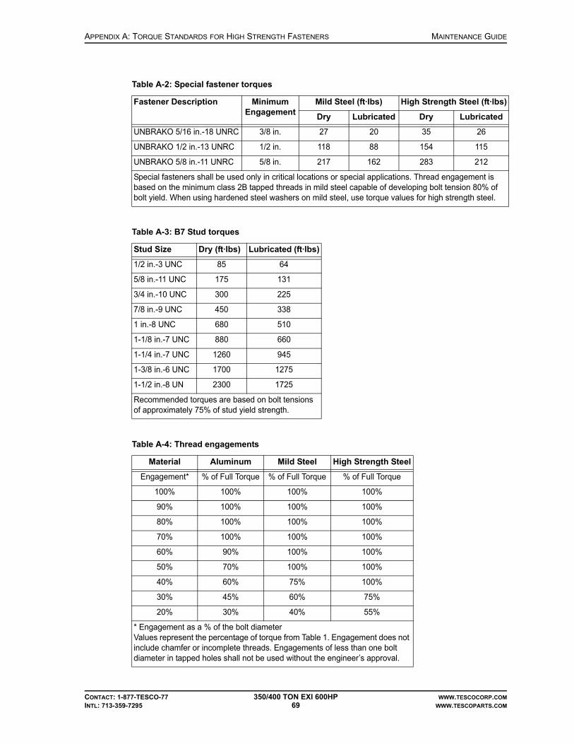
APPENDIX A: TORQUE STANDARDS FOR HIGH STRENGTH FASTENERS MAINTENANCE GUIDE
CONTACT: 1-877-TESCO-77 350/400 TON EXI 600HP WWW.TESCOCORP.COM
INTL: 713-359-7295 69 WWW.TESCOPARTS.COM
Table A-2: Special fastener torques
Fastener Description Minimum Engagement
Mild Steel (ft·lbs) High Strength Steel (ft·lbs)
Dry Lubricated Dry Lubricated
UNBRAKO 5/16 in.-18 UNRC 3/8 in. 27 20 35 26
UNBRAKO 1/2 in.-13 UNRC 1/2 in. 118 88 154 115
UNBRAKO 5/8 in.-11 UNRC 5/8 in. 217 162 283 212
Special fasteners shall be used only in critical locations or special applications. Thread engagement is based on the minimum class 2B tapped threads in mild steel capable of developing bolt tension 80% of bolt yield. When using hardened steel washers on mild steel, use torque values for high strength steel.
Table A-3: B7 Stud torques
Stud Size Dry (ft·lbs) Lubricated (ft·lbs)
1/2 in.-3 UNC 85 64
5/8 in.-11 UNC 175 131
3/4 in.-10 UNC 300 225
7/8 in.-9 UNC 450 338
1 in.-8 UNC 680 510
1-1/8 in.-7 UNC 880 660
1-1/4 in.-7 UNC 1260 945
1-3/8 in.-6 UNC 1700 1275
1-1/2 in.-8 UN 2300 1725
Recommended torques are based on bolt tensions of approximately 75% of stud yield strength.
Table A-4: Thread engagements
Material Aluminum Mild Steel High Strength Steel
Engagement* % of Full Torque % of Full Torque % of Full Torque
100% 100% 100% 100%
90% 100% 100% 100%
80% 100% 100% 100%
70% 100% 100% 100%
60% 90% 100% 100%
50% 70% 100% 100%
40% 60% 75% 100%
30% 45% 60% 75%
20% 30% 40% 55%
* Engagement as a % of the bolt diameterValues represent the percentage of torque from Table 1. Engagement does not include chamfer or incomplete threads. Engagements of less than one bolt diameter in tapped holes shall not be used without the engineer’s approval.

MAINTENANCE GUIDE APPENDIX A: TORQUE STANDARDS FOR HIGH STRENGTH FASTENERS
CONTACT: 1-877-TESCO-77 350/400 TON EXI 600HP WWW.TESCOCORP.COM
INTL: 713-359-7295 70 WWW.TESCOPARTS.COM
This page has been left blank intentionally.

APPENDIX B: TOOL JOINT USAGE CHART MAINTENANCE GUIDE
CONTACT: 1-877-TESCO-77 350/400 TON EXI 600HP WWW.TESCOCORP.COM
INTL: 713-359-7295 71 WWW.TESCOPARTS.COM
APPENDIX B: TOOL JOINT USAGE CHART
Use the following chart to configure the grabber and grabber dies to accommodate the current drill pipe.
Table B-1: Tool joint usage chart
Tool Joint O.D. TESCO Part # Qty Description
3-1/8 in. – 6-5/8 in. 3051 2 Die holder
1047 8 Socket head capscrew, 1/2-13UNC x 2-1/2 in.
3054 2 Bottom keeper plate
8378 2 Top die retainer plate
3725 4 Hex head capscrew, 3/8-16UNC x 1 in.
1045 4 Socket head capscrew, 1/2-13UNC x 1 in.
6654 2 Spacer
9070 4 Tong die, 1 in. thick x 1-1/4 in. wide x 5-7/8 in. long
4891 (opt.) 4 Tong die, 1 in. thick x 1-1/4 in. wide x 3-7/8 in. long
3055 (opt.) 4 Die spacer
4 in. – 7-1/2 in. 3051 2 Die holder
1047 8 Socket head capscrew, 1/2-13UNC x 2-1/2 in.
3054 2 Bottom keeper plate
8378 2 Top die retainer plate
3725 4 Hex head capscrew, 3/8-16UNC x 1 in.
1045 4 Socket head capscrew, 1/2-13UNC x 1 in.
6654 2 Spacer
1676 4 Tong die, 1/2 in. thick x 1-1/4 in. wide x 5-7/8 in. long
2526 (opt.) 4 Tong die, 1/2 in. thick x 1-1/4 in. wide x 3-7/8 in. long
3055 (opt.) 4 Die spacer
5 in. – 8-1/2 in. (standard)
3051 2 Die holder
1044 8 Socket head capscrew, 1/2-13UNC x 1 in.
3054 2 Bottom keeper plate
1045 4 Socket head capscrew, 1/2-13UNC x 1 in.
1676 4 Tong die, 1/2 in. thick x 1-1/4 in. wide x 5-7/8 in. long
2526 (opt.) 4 Tong die, 1/2 in. thick x 1-1/4 in. wide x 3-7/8 in. long
3055 (opt.) 4 Die spacer
8-1/2 in. – 8-3/4 in. 8760 2 Die holder
1045 4 Socket head capscrew, 1/2-13UNC x 1 in.
7443 2 Shim, 1/8 in.
1676 4 Tong die, 1/2 in. thick x 1-1/4 in. wide x 5-7/8 in. long
2526 (opt.) 4 Tong die, 1/2 in. thick x 1-1/4 in. wide x 3-7/8 in. long
3055 (opt.) 4 Die spacer

MAINTENANCE GUIDE APPENDIX B: TOOL JOINT USAGE CHART
CONTACT: 1-877-TESCO-77 350/400 TON EXI 600HP WWW.TESCOCORP.COM
INTL: 713-359-7295 72 WWW.TESCOPARTS.COM
Table B-2: Tool joint usage chart
Tool Joint O.D.TESCO Part
#Qty Description
2-7/8 in. – 4 in. 5807 4 Die holder retainer, for 1/2 in. shims
5808 2 Shim, 1/2 in.
7588 4 Tong die, 1 in. thick x 1-1/4 in. wide x 5 in. long
3852 2 Break-away tab
6244 2 Die retainer
8626 8 Cap screw, hex head, 3/8 in. x 1-1/2 in.
3-1/4 in. – 4-1/2 in. 5807 4 Die holder retainer, for 1/2 in. shims
5808 2 Shim, 1/2 in.
1677 4 Tong die, 1 in. thick x 1-1/4 in. wide x 5 in. long
3852 2 Break-away tab
6244 2 Die retainer
8626 8 Cap screw, hex head, 3/8 in. x 1-1/2 in.
3-1/2 in.– 6-5/8 in. 3845 4 Die holder retainer
1677 4 Tong die, 1 in. thick x 1-1/4 in. wide x 5 in. long
3852 2 Break-away tab
6244 2 Die retainer
3725 8 Cap screw, hex head, 3/8 in. x 1 in.

APPENDIX C: MUD LOGGER OUTPUTS MAINTENANCE GUIDE
CONTACT: 1-877-TESCO-77 350/400 TON EXI 600HP WWW.TESCOCORP.COM
INTL: 713-359-7295 73 WWW.TESCOPARTS.COM
APPENDIX C: MUD LOGGER OUTPUTS
TESCO provides a single output for logging services. The mud logger output from the TESCO Power Module Building ‘G’ cord provides a signal for quill rpm and quill torque. The mud logger signals can be assessed for quill speed and torque via a receptacle provided for that purpose in the “Load Supply” waterfall in the Power Module Building.
Both signals are a 4 - 20mA analog signal. The mudlogger outputs are driven from a PLC analog output module. Refer to the electrical drawing package for the schematics of the particular top drive unit.
If specification data, or additional or alternate outputs are required, contact a qualified TESCO representative.
Figure C-1: Checking analog mud logger outputs

MAINTENANCE GUIDE APPENDIX C: MUD LOGGER OUTPUTS
CONTACT: 1-877-TESCO-77 350/400 TON EXI 600HP WWW.TESCOCORP.COM
INTL: 713-359-7295 74 WWW.TESCOPARTS.COM
This page has been left blank intentionally.

APPENDIX D: TORQUE SPECIFICATION OF ELECTRICAL FASTENERS MAINTENANCE GUIDE
CONTACT: 1-877-TESCO-77 350/400 TON EXI 600HP WWW.TESCOCORP.COM
INTL: 713-359-7295 75 WWW.TESCOPARTS.COM
APPENDIX D: TORQUE SPECIFICATION OF ELECTRICAL FASTENERS
Table D-1: Torque specification of electrical fasteners
Item value unit value unit
10-32 UNF x 1/2” machine screw 25 - 30 in-lb 2.82 - 3.39 N-m
M12 x 45 hex head screw 35 - 44 lb-ft 47.5 - 59.7 N-m
M12 x 35 hex head screw 35 - 44 lb-ft 47.5 - 59.7 N-m
M8 x 25 hex head screw 16 - 19 lb-ft 21.7 - 25.8 N-m
M8 x 16 hex head screw 16 - 19 lb-ft 21.7 - 25.8 N-m
5/16” UNC x 3/4” hex head screw 16 - 19 lb-ft 21.7 - 25.8 N-m
5/16” UNC x 1” hex head screw 16 - 19 lb-ft 21.7 - 25.8 N-m
3/8” UNC x 1.75” hex head screw 25 - 30 lb-ft 34 - 40.7 N-m
10-32 UNF x 3/4” hex head screw 25 - 30 in-lb 34 - 40.7 N-m
6-32” UNC x 3/4” hex head screw 8 - 10 in-lb 0.9 - 1.13 N-m
10-32 UNF x 1/25” hex head screw 25 - 30 in-lb 2.82 - 3.39 N-m
5/8” UNC x 1.75” hex head screw 145 - 174 lb-ft 197 - 236 N-m

MAINTENANCE GUIDE APPENDIX D: TORQUE SPECIFICATION OF ELECTRICAL FASTENERS
CONTACT: 1-877-TESCO-77 350/400 TON EXI 600HP WWW.TESCOCORP.COM
INTL: 713-359-7295 76 WWW.TESCOPARTS.COM
This page has been left blank intentionally.

APPENDIX E: SAMPLE INSPECTION LOGS MAINTENANCE GUIDE
CONTACT: 1-877-TESCO-77 350/400 TON EXI 600HP WWW.TESCOCORP.COM
INTL: 713-359-7295 77 WWW.TESCOPARTS.COM
APPENDIX E: SAMPLE INSPECTION LOGS
The following pages contain examples of inspection logs. It is important to keep detailed inspection records for all load path and torque arrest system components. Please use the following pages as a guide.
Use this log to schedule and track inspections for each load path component.
In this field Do this
Serial Number Record the component serial number.
Inspection Date Enter the date of the most recent component inspection.
Days in Service Enter the cumulative hours (or days) of service the component has been in service on the date of inspection.
Inspected By Enter the name of the company that performed the inspection.Note: Attach a copy of the inspection results to this inspection log.
Results/Comments Summarize the test results, and note any special action taken in the Additional Comments section at the bottom of the page. If a component is replaced, include the serial number for the replacement part.
Next Service Due Enter the hours (or days) of service when the component requires its next inspection.
Additional Comments Enter additional information as required.

MAINTENANCE GUIDE APPENDIX E: SAMPLE INSPECTION LOGS
CONTACT: 1-877-TESCO-77 350/400 TON EXI 600HP WWW.TESCOCORP.COM
INTL: 713-359-7295 78 WWW.TESCOPARTS.COM
QUILL INSPECTION LOG
Additional Comments:
Top Drive Number: Service Facility: Service Activation Date:
Top Drive Type: Location: Other:
Serial #Inspection
DateDays in Service
(Cumulative)Inspected By Results/Comments
Next Service Due
Good Condition Repaired Replaced
Good Condition Repaired Replaced
Good Condition Repaired Replaced
Good Condition Repaired Replaced
Good Condition Repaired Replaced
Good Condition Repaired Replaced
Good Condition Repaired Replaced

APPENDIX E: SAMPLE INSPECTION LOGS MAINTENANCE GUIDE
CONTACT: 1-877-TESCO-77 350/400 TON EXI 600HP WWW.TESCOCORP.COM
INTL: 713-359-7295 79 WWW.TESCOPARTS.COM
LOAD NUT RETAINER AND SPLIT COLLAR INSPECTION LOG
Additional Comments:
Top Drive Number: Service Facility: Service Activation Date:
Top Drive Type: Location: Other:
Serial #Inspection
DateDays in Service
(Cumulative)Inspected By Results/Comments
Next Service Due
Good Condition Repaired Replaced
Good Condition Repaired Replaced
Good Condition Repaired Replaced
Good Condition Repaired Replaced
Good Condition Repaired Replaced
Good Condition Repaired Replaced
Good Condition Repaired Replaced
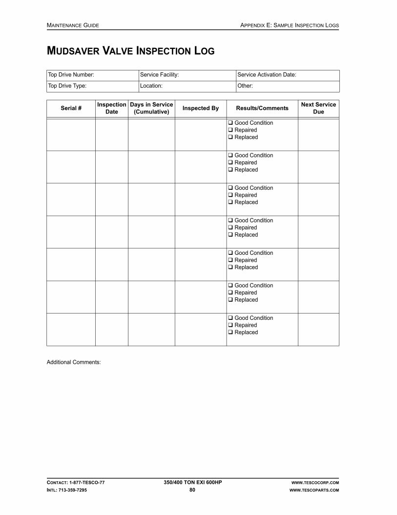
MAINTENANCE GUIDE APPENDIX E: SAMPLE INSPECTION LOGS
CONTACT: 1-877-TESCO-77 350/400 TON EXI 600HP WWW.TESCOCORP.COM
INTL: 713-359-7295 80 WWW.TESCOPARTS.COM
MUDSAVER VALVE INSPECTION LOG
Additional Comments:
Top Drive Number: Service Facility: Service Activation Date:
Top Drive Type: Location: Other:
Serial #Inspection
DateDays in Service
(Cumulative)Inspected By Results/Comments
Next Service Due
Good Condition Repaired Replaced
Good Condition Repaired Replaced
Good Condition Repaired Replaced
Good Condition Repaired Replaced
Good Condition Repaired Replaced
Good Condition Repaired Replaced
Good Condition Repaired Replaced

APPENDIX E: SAMPLE INSPECTION LOGS MAINTENANCE GUIDE
CONTACT: 1-877-TESCO-77 350/400 TON EXI 600HP WWW.TESCOCORP.COM
INTL: 713-359-7295 81 WWW.TESCOPARTS.COM
SAVER SUB INSPECTION LOG
Additional Comments:
Top Drive Number: Service Facility: Service Activation Date:
Top Drive Type: Location: Other:
Serial #Inspection
DateDays in Service
(Cumulative)Inspected By Results/Comments
Next Service Due
Good Condition Repaired Replaced
Good Condition Repaired Replaced
Good Condition Repaired Replaced
Good Condition Repaired Replaced
Good Condition Repaired Replaced
Good Condition Repaired Replaced
Good Condition Repaired Replaced

MAINTENANCE GUIDE APPENDIX E: SAMPLE INSPECTION LOGS
CONTACT: 1-877-TESCO-77 350/400 TON EXI 600HP WWW.TESCOCORP.COM
INTL: 713-359-7295 82 WWW.TESCOPARTS.COM
LOAD COLLAR INSPECTION LOG
Additional Comments:
Top Drive Number: Service Facility: Service Activation Date:
Top Drive Type: Location: Other:
Serial #Inspection
DateDays in Service
(Cumulative)Inspected By Results/Comments
Next Service Due
Good Condition Repaired Replaced
Good Condition Repaired Replaced
Good Condition Repaired Replaced
Good Condition Repaired Replaced
Good Condition Repaired Replaced
Good Condition Repaired Replaced
Good Condition Repaired Replaced

APPENDIX E: SAMPLE INSPECTION LOGS MAINTENANCE GUIDE
CONTACT: 1-877-TESCO-77 350/400 TON EXI 600HP WWW.TESCOCORP.COM
INTL: 713-359-7295 83 WWW.TESCOPARTS.COM
ELEVATOR LINKS INSPECTION LOG
Additional Comments:
Top Drive Number: Service Facility: Service Activation Date:
Top Drive Type: Location: Other:
Serial #Inspection
DateDays in Service
(Cumulative)Inspected By Results/Comments
Next Service Due
Good Condition Repaired Replaced
Good Condition Repaired Replaced
Good Condition Repaired Replaced
Good Condition Repaired Replaced
Good Condition Repaired Replaced
Good Condition Repaired Replaced
Good Condition Repaired Replaced

MAINTENANCE GUIDE APPENDIX E: SAMPLE INSPECTION LOGS
CONTACT: 1-877-TESCO-77 350/400 TON EXI 600HP WWW.TESCOCORP.COM
INTL: 713-359-7295 84 WWW.TESCOPARTS.COM
ELEVATOR INSPECTION LOG
Additional Comments:
Top Drive Number: Service Facility: Service Activation Date:
Top Drive Type: Location: Other:
Serial #Inspection
DateDays in Service
(Cumulative)Inspected By Results/Comments
Next Service Due
Good Condition Repaired Replaced
Good Condition Repaired Replaced
Good Condition Repaired Replaced
Good Condition Repaired Replaced
Good Condition Repaired Replaced
Good Condition Repaired Replaced
Good Condition Repaired Replaced

APPENDIX F: SERVICE CHECKLISTS MAINTENANCE GUIDE
CONTACT: 1-877-TESCO-77 350/400 TON EXI 600HP WWW.TESCOCORP.COM
INTL: 713-359-7295 85 WWW.TESCOPARTS.COM
APPENDIX F: SERVICE CHECKLISTS
This Appendix contains examples of the following checklists:
• Daily Checklist (see also Maintenance and Service Schedules)• Weekly Checklist (see also Maintenance and Service Schedules)• Monthly Checklist (see also Maintenance and Service Schedules)• Megger Test Chart
DAILY CHECKLISTS
Daily: Top Drive
IMPORTANT: This equipment was filled at the factory with TESCO ULTREX brand fluids and greases. To ensure maximum performance and to avoid cross-contamination, we strongly recommend the continued usage of TESCO ULTREX lubricants, unless otherwise specified.
Date: Supervisor:
Rig: Time:
Inspect For Inspector
Gearbox oil level correct gearbox oil level (halfway up sight glass)
Hydraulic hoses and connections at the top drive
leaks
Blower motor abnormal noise; correct operation
Lubricate With Inspector
Upper quill bearing retainer (1) TESCO ULTREX, NLGI #1 or 2
Lower quill bearing retainer (1) TESCO ULTREX, NLGI #1 or 2
Upper input shaft retainer (1) TESCO ULTREX, NLGI #1 or 2
Lower input shaft retainer (1) TESCO ULTREX, NLGI #1 or 2
Load collar grease port (1) TESCO ULTREX, NLGI #1 or 2
Tilt cylinders (4) TESCO ULTREX, NLGI #1 or 2
Extend cylinders (4) TESCO ULTREX, NLGI #1 or 2
Elevator handle pins (2) TESCO ULTREX, NLGI #1 or 2
Elevator hinge pin (1) TESCO ULTREX, NLGI #1 or 2
Mud valve actuator (1) TESCO ULTREX, NLGI #1 or 2
Pipe handler lock (1) TESCO ULTREX, NLGI #1 or 2
Swivel pins (6) TESCO ULTREX, NLGI #1 or 2

MAINTENANCE GUIDE APPENDIX F: SERVICE CHECKLISTS
CONTACT: 1-877-TESCO-77 350/400 TON EXI 600HP WWW.TESCOCORP.COM
INTL: 713-359-7295 86 WWW.TESCOPARTS.COM
Daily: Torque Arrest System
Daily: Auxiliary Hydraulic Power Unit
Daily: Power Module
Yoke pins (6) TESCO ULTREX, NLGI #1 or 2
Wash pipe (1) TESCO ULTREX, NLGI #1 or 2
Inspect For Inspector
All pinned connections damage or decay/corrosion
All overhead equipment (T-bar, torque beam, torque track, torque bushing)
damage or decay/corrosion
Inspect For Inspector
Auxiliary hydraulic oil tank correct oil level
Inspect For Inspector
Drive componentsCaution: Condensation in the drive components can cause severe damage if not immediately addressed. See “Condensation” on page 14
moisture
Indicator lights on PLC panel correct function (replace if required)
VFD for blower motor proper operation
Door fans on VFD cabinets proper operation
ESD push button correct function (replace if required)
Braking resistor module for signs of overheating, damage or decay
Comments/Notes:
Lubricate With Inspector

APPENDIX F: SERVICE CHECKLISTS MAINTENANCE GUIDE
CONTACT: 1-877-TESCO-77 350/400 TON EXI 600HP WWW.TESCOCORP.COM
INTL: 713-359-7295 87 WWW.TESCOPARTS.COM
WEEKLY CHECKLISTS
Weekly: Top Drive
Weekly: Service Loop
Date: Supervisor:
Rig: Time:
Inspect For Inspector
Hydraulic fittings tightness/leaks
Mud saver valve actuator sleeve general condition; disassemble, clean, grease, coat with corrosion inhibitor and reinstall
Counter-balance system cushion height = 2”
Motor termination boxes • moisture• tightness of all terminal block screws• tightness of all bus bar bolts• evidence of arcing
Robotics and sensor panels • moisture• tightness of wire terminations
Gearbox lubrication filter • cleanliness• check filter bypass and magnetic plug
Pipe handler rotation motors check for tightness
Load collar springs • damage• breaks
Inspect For Inspector
All service loop components damage, excessive wear
Urethane capture blocks(at top drive and roller saddle)
hose placement, tightness
Fluid quick couplers (auxiliary hydraulics)
damage or decay, tightness
All cable connections and cables(power, sensor, robotics, and ground cables)
damage, tightness, and scuffing
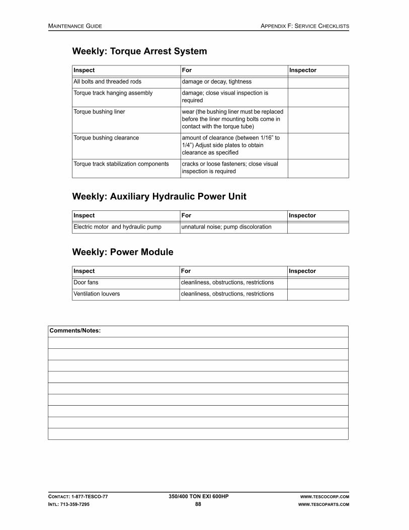
MAINTENANCE GUIDE APPENDIX F: SERVICE CHECKLISTS
CONTACT: 1-877-TESCO-77 350/400 TON EXI 600HP WWW.TESCOCORP.COM
INTL: 713-359-7295 88 WWW.TESCOPARTS.COM
Weekly: Torque Arrest System
Weekly: Auxiliary Hydraulic Power Unit
Weekly: Power Module
Inspect For Inspector
All bolts and threaded rods damage or decay, tightness
Torque track hanging assembly damage; close visual inspection is required
Torque bushing liner wear (the bushing liner must be replaced before the liner mounting bolts come in contact with the torque tube)
Torque bushing clearance amount of clearance (between 1/16” to 1/4”) Adjust side plates to obtain clearance as specified
Torque track stabilization components cracks or loose fasteners; close visual inspection is required
Inspect For Inspector
Electric motor and hydraulic pump unnatural noise; pump discoloration
Inspect For Inspector
Door fans cleanliness, obstructions, restrictions
Ventilation louvers cleanliness, obstructions, restrictions
Comments/Notes:

APPENDIX F: SERVICE CHECKLISTS MAINTENANCE GUIDE
CONTACT: 1-877-TESCO-77 350/400 TON EXI 600HP WWW.TESCOCORP.COM
INTL: 713-359-7295 89 WWW.TESCOPARTS.COM
MONTHLY CHECKLISTS
Monthly: Top Drive
Date: Supervisor:
Rig: Time:
Inspect For Inspector
Grabber dies excessive wear
11-station manifold general condition/leaks
Load collar correct spacing between load collar and load nut must be 0.25”
Quill end play no end play (see “How to Check for Quill End Play” on page 47)
Main auxiliary hydraulics relief valve correct setting (see “How to Set the Main Pressure Relief Valve for the Auxiliary System” on page 45)
Mud valve (lower ball) manually operate to ensure correct function
All fasteners (nuts, bolts, and lock wires)
correct location, tightness
Top drive hydraulic connections and hoses
oil leaks/deformation
Saver sub threads excessive thread wear, seal face condition
Connection locking clamps correct location, tightness
Grabber leg safety chain/shackles broken components/lock wires
Pipe bumper/motor guard dents or bends that may indicate bolt damage
Hammer union on Kelly hose integrity and tightness
Grabber/drawworks and mud valve/mud pump interlocks
function test
Gearbox lubrication system hoses • oil leaks• adequate circulation (press 60 to 120 psi when warm)
Gearbox oil analysis abnormalities (take samples to test for water, metal particles, etc.; every 900 operating hours)
Torque bushing wear liners wear and damage
Wash pipe leakage
Top drive electric connectors damage, tightness

MAINTENANCE GUIDE APPENDIX F: SERVICE CHECKLISTS
CONTACT: 1-877-TESCO-77 350/400 TON EXI 600HP WWW.TESCOCORP.COM
INTL: 713-359-7295 90 WWW.TESCOPARTS.COM
Monthly Driller’s Panel
Monthly: Service Loop
Monthly: Auxiliary Hydraulic Power Unit
Lubricate With Inspector
Hinge pins and extend frame spray with penetrating oil (WD 40, or spray lithium)
Main Motor/ Input shaft splines TESCO Ultrex, NLGI #1 or 2
Inspect For
Wire terminals in the driller’s panel tightness
Versa Max modules locked in place
Indication lights working
Switch contact blocks tightness
Inspect For
All multi-conductor connections moisture, dirt; open and check, then spray with electrical cleaner/moisture dispersant
Main service cable connectors (power, sensor, robotics, ground cables)
cleanliness; open, clean, reinstall
Inspect For Inspector
Hydraulic system pressure relief valve correct setting as per hydraulic schematic
Auxiliary system function light pressure switch
correct setting
Auxiliary hydraulic filter cleanliness; inspect and change if required
Auxiliary hydraulic fluid complete fluid analysis

APPENDIX F: SERVICE CHECKLISTS MAINTENANCE GUIDE
CONTACT: 1-877-TESCO-77 350/400 TON EXI 600HP WWW.TESCOCORP.COM
INTL: 713-359-7295 91 WWW.TESCOPARTS.COM
Monthly: Power Module
Warning! Do not perform he following checks unless the main breaker panel is disconnected and locked out.
Warning! Only qualified personnel should perform the following maintenance activities.
Inspect For Inspector
All wire terminal screws tightness
All bolted connections on both the incoming and outgoing waterfall
tightness
All bolted connections inside 600V panel tightness
VFD input and output power connections correct position and tightness
Electrical connections for the main drive components
correct torqueCritical: These connections must be torqued to specification. Severe component damage can result if they are over-tightened.
Comments/Notes:
!
!

MAINTENANCE GUIDE APPENDIX F: SERVICE CHECKLISTS
CONTACT: 1-877-TESCO-77 350/400 TON EXI 600HP WWW.TESCOCORP.COM
INTL: 713-359-7295 92 WWW.TESCOPARTS.COM
MEGGER TEST CHART
Set the Megger to 1000V/2000Mohm. Test for 5 seconds. Use this chart to record the test results for the following:
• feed cable connections to drive motors• motor connection terminals
Motor and Pigtail
Service Loop
Any reading below 1 mega-ohm at 1,000 volts is unacceptable. Any reading below 5 mega-ohms at 1,000 volts should be flagged.
Grd A B C
A X
B X X
C X X X
Grd A B C
A X
B X
C X

APPENDIX F: SERVICE CHECKLISTS MAINTENANCE GUIDE
CONTACT: 1-877-TESCO-77 350/400 TON EXI 600HP WWW.TESCOCORP.COM
INTL: 713-359-7295 93 WWW.TESCOPARTS.COM
TESCO ULTREX™ LUBRICANTS
Quick Reference Guide
Engine’s Component Description
Fluid Description TESCO Part #
60 Series Detroit Advanced Formula Synthetic Blend Motor Oil SAE 15W-40 731134
12 V 2000 Series Detroit Advanced Formula Synthetic Blend Motor Oil SAE 15W-40 731134
16 V 2000 Series Detroit Advanced Formula Synthetic Blend Motor Oil SAE 15W-40 731134
All CAT Engines Advanced Formula Synthetic Blend Motor Oil SAE 15W-40 731134
12 V 92 Detroit Advanced Formula Single Weight Motor Oil SAE 40 731135
16 V 92 Detroit Advanced Formula Single Weight Motor Oil SAE 40 731135
Gear Boxes Hydraulic Top Drive’s Component Description
Fluid Description TESCO Part #
HMI(S) Advanced Performance Multi Grade Gear Oil 80W-90 731140
HS Advanced Performance Multi Grade Gear Oil 80W-90 731140
HC Advanced Performance Multi Grade Gear Oil 80W-90 731140
HCI Advanced Performance Multi Grade Gear Oil 80W-90 731140
HXI Advanced Performance Multi Grade Gear Oil 80W-90 731140
Gear Boxes Electric Top Drive’s Component Description
Fluid Description TESCO Part #
ECI 900/1350 Synthetic Multi Grade Gear Oil 75W-90 731136
EMI 450 Synthetic Multi Grade Gear Oil 75W-90 731136
EMI 400 Synthetic Multi Grade Gear Oil 75W-90 731136
EXI Synthetic Multi Grade Gear Oil 75W-90 731136
EMI 400 (H&P) Advanced Performance Gear and Bearing Oil ISO 220 731133
All TESCO Manufactured Pump Drives
Fluid Description TESCO Part #
Advanced Formula Single Weight Motor Oil SAE 40 731135
All Swivels Fluid Description TESCO Part #
Advanced Performance Gear and Bearing Oil ISO 220 731133
Advanced Performance Multi Grade Gear Oil 80W-90 731140
All TESCO Hydraulic Systems Fluid Description (either can be used) TESCO Part #
Advanced Performance Hydraulic Oil ISO 68 731143
Biodegradeable Hydraulic Oil ISO 68 731138
Grease for All TESCO Top Drives
Fluid Description (either can be used) TESCO Part #
NLGI #1 (cold weather) 48 tubes 731142-48T
NLGI #2 (hot weather) 48 tubes 731141-48T

MAINTENANCE GUIDE APPENDIX F: SERVICE CHECKLISTS
CONTACT: 1-877-TESCO-77 350/400 TON EXI 600HP WWW.TESCOCORP.COM
INTL: 713-359-7295 94 WWW.TESCOPARTS.COM
Oil Lubricants

APPENDIX F: SERVICE CHECKLISTS MAINTENANCE GUIDE
CONTACT: 1-877-TESCO-77 350/400 TON EXI 600HP WWW.TESCOCORP.COM
INTL: 713-359-7295 95 WWW.TESCOPARTS.COM

MAINTENANCE GUIDE APPENDIX F: SERVICE CHECKLISTS
CONTACT: 1-877-TESCO-77 350/400 TON EXI 600HP WWW.TESCOCORP.COM
INTL: 713-359-7295 96 WWW.TESCOPARTS.COM

APPENDIX F: SERVICE CHECKLISTS MAINTENANCE GUIDE
CONTACT: 1-877-TESCO-77 350/400 TON EXI 600HP WWW.TESCOCORP.COM
INTL: 713-359-7295 97 WWW.TESCOPARTS.COM

MAINTENANCE GUIDE APPENDIX F: SERVICE CHECKLISTS
CONTACT: 1-877-TESCO-77 350/400 TON EXI 600HP WWW.TESCOCORP.COM
INTL: 713-359-7295 98 WWW.TESCOPARTS.COM

APPENDIX F: SERVICE CHECKLISTS MAINTENANCE GUIDE
CONTACT: 1-877-TESCO-77 350/400 TON EXI 600HP WWW.TESCOCORP.COM
INTL: 713-359-7295 99 WWW.TESCOPARTS.COM

MAINTENANCE GUIDE APPENDIX F: SERVICE CHECKLISTS
CONTACT: 1-877-TESCO-77 350/400 TON EXI 600HP WWW.TESCOCORP.COM
INTL: 713-359-7295 100 WWW.TESCOPARTS.COM
Grease Lubricants

APPENDIX F: SERVICE CHECKLISTS MAINTENANCE GUIDE
CONTACT: 1-877-TESCO-77 350/400 TON EXI 600HP WWW.TESCOCORP.COM
INTL: 713-359-7295 101 WWW.TESCOPARTS.COM

MAINTENANCE GUIDE APPENDIX F: SERVICE CHECKLISTS
CONTACT: 1-877-TESCO-77 350/400 TON EXI 600HP WWW.TESCOCORP.COM
INTL: 713-359-7295 102 WWW.TESCOPARTS.COM

APPENDIX F: SERVICE CHECKLISTS MAINTENANCE GUIDE
CONTACT: 1-877-TESCO-77 350/400 TON EXI 600HP WWW.TESCOCORP.COM
INTL: 713-359-7295 103 WWW.TESCOPARTS.COM

MAINTENANCE GUIDE APPENDIX F: SERVICE CHECKLISTS
CONTACT: 1-877-TESCO-77 350/400 TON EXI 600HP WWW.TESCOCORP.COM
INTL: 713-359-7295 104 WWW.TESCOPARTS.COM
This page has been left blank intentionally.

INDEX MAINTENANCE GUIDE
CONTACT: 1-877-TESCO-77 350/400 TON EXI 600HP WWW.TESCOCORP.COM
INTL: 713-359-7295 105 WWW.TESCOPARTS.COM
INDEX
Numerics1,000 operating day service
auxiliary hydraulic power unit, 14service loop, 12top drive, 8
120/208 VAC panel storage, 66600 VAC panel storage, 66
Aactuating piston, grabber, 54actuator/valve orientation, 41assembly and disassembly instructions, 51auxiliary hydraulic power unit
1,000 operating day service, 14daily service, 13monthly service, 13storage, 65weekly service, 13
auxiliary systemfunctional light pressure switch, 46main pressure relief valve, 45secondary pressure relief valve, 44
Ccables and hoses storage, 63commissioning, 1component inspection guidelines, 18condensation, 14counter-balance height, 42
Ddaily inspection
top drive gearbox oil, 5torque arrest system, 12
daily serviceauxiliary hydraulic power unit, 13power module, 14top drive, 5
disassembly/assembly instructions, 51drill ahead, 1driller’s panel
functions, 1monthly service, 11storage, 63
drive system storage, 66
Eelectrical schematics, 1elevator storage, 62extend frame
monthly lubrication, 8, 13storage, 64
Ffluid specification and capacity summary, 5
Ggearbox inspection, 34gearbox lubrication schematics, 1general maintenance areas, 38grabber
change grabber dies, 53service actuating piston, 54
grabber actuating pistonreinstallation, 56removing, 54
grabber cylinder repair, 56grabber dies, changing, 53grabber disassembly and assembly, 53grabber leg
reinstallation, 58removing, 58
grabber storage, 61guidelines for component inspectors, 18
Hhanging assembly storage, 65high strength fasteners, torque standards, 67hinge pins monthly lubrication, 8, 13hose saddle storage, 65hydraulic schematics, 1
Iinformation
where to find more, 1inspection of load path components
elevator links (bails), 27elevators, 28load collar, 26load nut, 23mudsaver valve and actuator, 24quill, 22saver sub, 25
MAINTENANCE GUIDE INDEX
CONTACT: 1-877-TESCO-77 350/400 TON EXI 600HP WWW.TESCOCORP.COM
INTL: 713-359-7295 106 WWW.TESCOPARTS.COM
swivel gearbox housing, 21yoke and link assembly, 19
inspection types, 19install the top drive, 1interlocks storage, 64
Jjunction boxes storage, 60
Lload nut
components inspection, 23storage, 60
lock-out methods, 3long term storage
120/208 VAC panel, 66600 VAC panel, 66auxiliary hydraulic power unit, 65before shut down, 59cables and hoses, 63driller’s panel, 63drive output waterfall, 66drive system, 66elevators, 62extend frame, 64grabber leg, 61hanging assembly, 65hose saddle, 65incoming waterfall, 66interlocks, 64junction boxes, 60load nut, 60mudsaver valve, 62pipe handler, 61power module, 66quill, 60saver subs, 63T-bar, 65top drive, 60torque arrest system, 64torque beam, 65torque bushing, 64torque tracks, 64
Mmake connections, 1megger test chart, 92monthly service
auxiliary hydraulic power unit, 13driller’s panel, 11main service cable connectors, 11power module, 15service loop, 11
top drive, 7MPI testing
pipe handler rotation system, 32torque arrest system, 29
mud logger outputs, 73mudsaver valve
installation, 51storage, 62
multi-conductor connections, monthly service, 11
Nnon-destructive testing
pipe handler rotation system components, 32schedules, 17torque arrest system, 29
Ooptions and spares, 1
Pparts lists, 1periodic magnetic particle inspection, 29pipe handler storage, 61power module
condensation, 14daily service, 14monthly service, 15service requirements, 14storage, 66thermostat settings, 15weekly service, 15
pre-operational checklists, 1
Qquick couplers, service loop, 11quill
end play, 47inspection, 22preload, 47preload calculation and adjustment, 48storage, 60
Rrig out, 1rig up, 1roto-actuator
disassemble, 40reassemble, 41service, 40
Ssample inspection logs, 77

INDEX MAINTENANCE GUIDE
CONTACT: 1-877-TESCO-77 350/400 TON EXI 600HP WWW.TESCOCORP.COM
INTL: 713-359-7295 107 WWW.TESCOPARTS.COM
saver subs storage, 63service cable monthly inspection, 11service checklists, 85service loop
1,000 operating day service, 12monthly service, 11quick couplers, 11service requirements, 11storage, 63weekly service, 11
service proceduresauxiliary function light, 46calculate preload adjustment, 48counter-balance height, 42quill end play, 47quill preload, 47roto-actuator, 40
service requirementsauxiliary hydraulic power unit, 13driller’s panel, 11power module, 14service loop, 11top drive, 5torque arrest system, 12
set torque and speed, 1stuck pipe, 1
TT-bar
daily inspection, 12storage, 65
testing inspection schedules, 17thermostat settings, 15threaded connections inspection, 29tool joint usage chart, 71top drive
1,000 operating day service, 8daily lubrication, 6daily service, 5lubrication points, 9monthly lubrication, 8, 13monthly service, 7service requirements, 5six-month lubrication, 8storage, 60weekly service, 6
top drive gearbox oil daily inspection, 5torque arrest system
daily service, 12long term storage, 64MPI testing, 29service requirements, 12weekly service, 12
torque beam
daily inspection, 12storage, 65
torque bushingdaily inspection, 12storage, 64
torque specification of electrical fasteners, 75torque standards for high strength fasteners, 67torque track
daily inspection, 12storage, 64
tripping operations, 1
UUltrex™ lubricants, 93
Wwaterfall storage, 66weekly inspection
fluid quick couplers, 11torque arrest system, 12urethane capture blocks, 11
weekly serviceauxiliary hydraulic power unit, 13power module, 15service loop, 11top drive, 6
WFMPI testing, 29

MAINTENANCE GUIDE INDEX
CONTACT: 1-877-TESCO-77 350/400 TON EXI 600HP WWW.TESCOCORP.COM
INTL: 713-359-7295 108 WWW.TESCOPARTS.COM
This page has been left blank intentionally.

MAINTENANCE GUIDE
CONTACT: 1-877-TESCO-77 350/400 TON EXI 600HP WWW.TESCOCORP.COM
INTL: 713-359-7295 109 WWW.TESCOPARTS.COM
ENGINEERING SIGN-OFF
This sign-off sheet indicates that this document has been approved for release by the Engineering Department at TESCO.
Document Complete By Signature Date Signed
Document Reviewed/Approved Date Signed
chane
Typewritten Text
Edward ChanSept. 28, 2009
madejskm
Typewritten Text
Oct 22, 2009

MAINTENANCE GUIDE
CONTACT: 1-877-TESCO-77 350/400 TON EXI 600HP WWW.TESCOCORP.COM
INTL: 713-359-7295 110 WWW.TESCOPARTS.COM
This page has been left blank intentionally.

DOCUMENT NAME: 1590030 REV 0
Electrical Troubleshooting Guide
EXI600 Top Drive System
600VAC 60Hz / 50Hz Spec
Guide for End Users
Danger! Only qualified personnel should inspect electrical systems.
!


ELECTRICAL TROUBLESHOOTING GUIDE COPYRIGHT AND DISCLAIMER
CONTACT: 1-877-TESCO-77 EXI 600 HP WWW.TESCOCORP.COM
INTL: 713-359-7295 I WWW.TESCOPARTS.COM
Tesco Corporation (“TESCO”) has made every effort to ensure that this document contains accurate and current information for the TESCO top drive, however, the document is intended to be used in conjunction with a complete training program and on-site supervision and TESCO does not warrant or guarantee that the information contained herein is either complete or accurate in every respect, and the reader hereby protects, indemnifies and holds harmless Tesco Corporation together with its directors, officers, employees and agents from and against all liability for personal injury, death or property damage to any person arising directly or indirectly from the use by the reader of the information contained in the document.
This equipment was filled at the factory with TESCO ULTREX™ brand fluids and greases. To ensure maximum performance and to avoid cross-contamination, we strongly recommend the continued usage of TESCO ULTREX™ lubricants, unless otherwise specified.
TESCO ULTREX™ is a trademark and TESCO® is a registered trademark of Tesco Corporation.
Tesco Corporation © 2009
Contact Information
Corporate Head Office3993 W. Sam Houston Parkway No., Suite 100
Houston, Texas, 77043USA
www.tescocorp.comwww.tescoparts.com
Telephone: (713) 359-7000Fax: (713) 359-7001
After Market Sales and Service ContactToll Free North America: 1-877-TESCO-77
International: 713-359-7295
REVISION INFORMATION ELECTRICAL TROUBLESHOOTING GUIDE
CONTACT: 1-877-TESCO-77 EXI 600 HP WWW.TESCOCORP.COM
INTL: 713-359-7295 II WWW.TESCOPARTS.COM
Revision Information
Version Date Description of Changes
Rev 0 Jan 2009 First release

ELECTRICAL TROUBLESHOOTING GUIDE TABLE OF CONTENTS
CONTACT: 1-877-TESCO-77 EXI 600 HP WWW.TESCOCORP.COM
INTL: 713-359-7295 III WWW.TESCOPARTS.COM
TABLE OF CONTENTS
Chapter 1: About This Document . . . . . . . . . . . . . . . . . . . . . . . . . . . . . . . . . . . . . . . . . . . . . 1
Chapter 2: Main Power. . . . . . . . . . . . . . . . . . . . . . . . . . . . . . . . . . . . . . . . . . . . . . . . . . . . . . 3
Main Distribution Power . . . . . . . . . . . . . . . . . . . . . . . . . . . . . . . . . . . . . . . . . . . . . . . . . . . . . . . . . . . . 3
No Power to Power Module Building (Main Interface Breaker Will Not Close). . . . . . . . . . . . . . . . . 3
Units Equipped with a Customer-provided Main Service ESD Interface Package . . . . . . . . . . . . . . . . . . . . . . . . . . . . . . . 3
Units Equipped with a TESCO Main Service ESD Interface Package. . . . . . . . . . . . . . . . . . . . . . . . . . . . . . . . . . . . . . . . . 4
Main Interface Breaker Over-current Tripping . . . . . . . . . . . . . . . . . . . . . . . . . . . . . . . . . . . . . . . . . 5
Main Interface Breaker Trips Persistently. . . . . . . . . . . . . . . . . . . . . . . . . . . . . . . . . . . . . . . . . . . . . 5
Bard HVAC Unit . . . . . . . . . . . . . . . . . . . . . . . . . . . . . . . . . . . . . . . . . . . . . . . . . . . . . . . . . . . . . . . . 6
Features: . . . . . . . . . . . . . . . . . . . . . . . . . . . . . . . . . . . . . . . . . . . . . . . . . . . . . . . . . . . . . . . . . . . . . . . . . . . . . . . . . . . . . . . 6
Chapter 3: Power Module . . . . . . . . . . . . . . . . . . . . . . . . . . . . . . . . . . . . . . . . . . . . . . . . . . . 7
Introduction: . . . . . . . . . . . . . . . . . . . . . . . . . . . . . . . . . . . . . . . . . . . . . . . . . . . . . . . . . . . . . . . . . . . . . 7
Major Components:. . . . . . . . . . . . . . . . . . . . . . . . . . . . . . . . . . . . . . . . . . . . . . . . . . . . . . . . . . . . . . . . 7
Drive System . . . . . . . . . . . . . . . . . . . . . . . . . . . . . . . . . . . . . . . . . . . . . . . . . . . . . . . . . . . . . . . . . . 7
Option 1: OEM3000 Drive . . . . . . . . . . . . . . . . . . . . . . . . . . . . . . . . . . . . . . . . . . . . . . . . . . . . . . . . . . . . . . . . . . . . . . . . . . 7
Option 2: ABB Drive. . . . . . . . . . . . . . . . . . . . . . . . . . . . . . . . . . . . . . . . . . . . . . . . . . . . . . . . . . . . . . . . . . . . . . . . . . . . . . . 7
Main Panel . . . . . . . . . . . . . . . . . . . . . . . . . . . . . . . . . . . . . . . . . . . . . . . . . . . . . . . . . . . . . . . . . . . . 7
600V Distribution Panel . . . . . . . . . . . . . . . . . . . . . . . . . . . . . . . . . . . . . . . . . . . . . . . . . . . . . . . . . . 8
Standard 60Hz Spec . . . . . . . . . . . . . . . . . . . . . . . . . . . . . . . . . . . . . . . . . . . . . . . . . . . . . . . . . . . . . . . . . . . . . . . . . . . . . . 8
Aux VFD 50Hz Spec . . . . . . . . . . . . . . . . . . . . . . . . . . . . . . . . . . . . . . . . . . . . . . . . . . . . . . . . . . . . . . . . . . . . . . . . . . . . . . 8
15KVA Transformer . . . . . . . . . . . . . . . . . . . . . . . . . . . . . . . . . . . . . . . . . . . . . . . . . . . . . . . . . . . . . 8
120/208VAC Distribution Panel . . . . . . . . . . . . . . . . . . . . . . . . . . . . . . . . . . . . . . . . . . . . . . . . . . . . 8
Drive and Building Cooling . . . . . . . . . . . . . . . . . . . . . . . . . . . . . . . . . . . . . . . . . . . . . . . . . . . . . . . . 8
HVAC unit. . . . . . . . . . . . . . . . . . . . . . . . . . . . . . . . . . . . . . . . . . . . . . . . . . . . . . . . . . . . . . . . . . . . . 8
Addressing General Issues . . . . . . . . . . . . . . . . . . . . . . . . . . . . . . . . . . . . . . . . . . . . . . . . . . . . . . . . . 9
Chopper Module . . . . . . . . . . . . . . . . . . . . . . . . . . . . . . . . . . . . . . . . . . . . . . . . . . . . . . . . . . . . . . . . 9
Resetting from Keypad . . . . . . . . . . . . . . . . . . . . . . . . . . . . . . . . . . . . . . . . . . . . . . . . . . . . . . . . . . . 9
Measuring mA for RPM and Torque from Power Module. . . . . . . . . . . . . . . . . . . . . . . . . . . . . . . . . 9
Motor Starters Issues . . . . . . . . . . . . . . . . . . . . . . . . . . . . . . . . . . . . . . . . . . . . . . . . . . . . . . . . . . . . . 10
Motor Keeps Quitting . . . . . . . . . . . . . . . . . . . . . . . . . . . . . . . . . . . . . . . . . . . . . . . . . . . . . . . . . . . 10
Motor Quits and Will Not Start . . . . . . . . . . . . . . . . . . . . . . . . . . . . . . . . . . . . . . . . . . . . . . . . . . . . 10
Motor is Not Receiving Power . . . . . . . . . . . . . . . . . . . . . . . . . . . . . . . . . . . . . . . . . . . . . . . . . . . . 11
Auxiliary hydraulic motor/pump issues . . . . . . . . . . . . . . . . . . . . . . . . . . . . . . . . . . . . . . . . . . . . . . 11
Auxiliary Pump Motor Will Not Start . . . . . . . . . . . . . . . . . . . . . . . . . . . . . . . . . . . . . . . . . . . . . . . . 11
Chapter 4: Top Drive Power / Control . . . . . . . . . . . . . . . . . . . . . . . . . . . . . . . . . . . . . . . . 13
To Power Up EXI 600 Top Drive . . . . . . . . . . . . . . . . . . . . . . . . . . . . . . . . . . . . . . . . . . . . . . . . . . . . . 13

TABLE OF CONTENTS ELECTRICAL TROUBLESHOOTING GUIDE
CONTACT: 1-877-TESCO-77 EXI 600 HP WWW.TESCOCORP.COM
INTL: 713-359-7295 IV WWW.TESCOPARTS.COM
In 600V Distribution Panel. . . . . . . . . . . . . . . . . . . . . . . . . . . . . . . . . . . . . . . . . . . . . . . . . . . . . . . .13
Standard 60Hz Spec. . . . . . . . . . . . . . . . . . . . . . . . . . . . . . . . . . . . . . . . . . . . . . . . . . . . . . . . . . . . . . . . . . . . . . . . . . . . . . 13
Aux VFD 50Hz Spec. . . . . . . . . . . . . . . . . . . . . . . . . . . . . . . . . . . . . . . . . . . . . . . . . . . . . . . . . . . . . . . . . . . . . . . . . . . . . . 13
In 208/120V Distribution Panel . . . . . . . . . . . . . . . . . . . . . . . . . . . . . . . . . . . . . . . . . . . . . . . . . . . .13
Inside the Main Panel . . . . . . . . . . . . . . . . . . . . . . . . . . . . . . . . . . . . . . . . . . . . . . . . . . . . . . . . . . .13
Start/Stop and Reset Top Drive . . . . . . . . . . . . . . . . . . . . . . . . . . . . . . . . . . . . . . . . . . . . . . . . . . . . .14
START/STOP . . . . . . . . . . . . . . . . . . . . . . . . . . . . . . . . . . . . . . . . . . . . . . . . . . . . . . . . . . . . . . . . .14
RESET . . . . . . . . . . . . . . . . . . . . . . . . . . . . . . . . . . . . . . . . . . . . . . . . . . . . . . . . . . . . . . . . . . . . . .15
Common Motor Issues . . . . . . . . . . . . . . . . . . . . . . . . . . . . . . . . . . . . . . . . . . . . . . . . . . . . . . . . . . . .15
Run with/without Encoder . . . . . . . . . . . . . . . . . . . . . . . . . . . . . . . . . . . . . . . . . . . . . . . . . . . . . . . .15
Motor Running in Reverse direction . . . . . . . . . . . . . . . . . . . . . . . . . . . . . . . . . . . . . . . . . . . . . . . .15
Blower motor is Not Running. . . . . . . . . . . . . . . . . . . . . . . . . . . . . . . . . . . . . . . . . . . . . . . . . . . . . .15
Blower Motor Starts but Quits After a Few Seconds . . . . . . . . . . . . . . . . . . . . . . . . . . . . . . . . . . . .15
Blower Motor Will Not Turn Off . . . . . . . . . . . . . . . . . . . . . . . . . . . . . . . . . . . . . . . . . . . . . . . . . . . .16
Motor Heater Function. . . . . . . . . . . . . . . . . . . . . . . . . . . . . . . . . . . . . . . . . . . . . . . . . . . . . . . . . . .16
Setting Gearbox Temperature Switch . . . . . . . . . . . . . . . . . . . . . . . . . . . . . . . . . . . . . . . . . . . . . . .16
Chapter 5: Hydraulic Functions . . . . . . . . . . . . . . . . . . . . . . . . . . . . . . . . . . . . . . . . . . . . . 17
DC Power Related Issues . . . . . . . . . . . . . . . . . . . . . . . . . . . . . . . . . . . . . . . . . . . . . . . . . . . . . . . . . .17
Hydraulic pump not running . . . . . . . . . . . . . . . . . . . . . . . . . . . . . . . . . . . . . . . . . . . . . . . . . . . . . . . .17
Chapter 6: Viewing Drive Parameters - ABB Drive . . . . . . . . . . . . . . . . . . . . . . . . . . . . . . 19
Drive System Description . . . . . . . . . . . . . . . . . . . . . . . . . . . . . . . . . . . . . . . . . . . . . . . . . . . . . . . . . .19
Overview . . . . . . . . . . . . . . . . . . . . . . . . . . . . . . . . . . . . . . . . . . . . . . . . . . . . . . . . . . . . . . . . . . . . .19
Drive Data Manager . . . . . . . . . . . . . . . . . . . . . . . . . . . . . . . . . . . . . . . . . . . . . . . . . . . . . . . . . . . .19
Drive Control with the Panel . . . . . . . . . . . . . . . . . . . . . . . . . . . . . . . . . . . . . . . . . . . . . . . . . . . . . . . . . . . . . . . . . . . . . . . . 19
Displaying Signals . . . . . . . . . . . . . . . . . . . . . . . . . . . . . . . . . . . . . . . . . . . . . . . . . . . . . . . . . . . . . .23
Selecting Actual Signals to Display . . . . . . . . . . . . . . . . . . . . . . . . . . . . . . . . . . . . . . . . . . . . . . . . . . . . . . . . . . . . . . . . . . 23
Displaying the Full Name of the Actual Signals . . . . . . . . . . . . . . . . . . . . . . . . . . . . . . . . . . . . . . . . . . . . . . . . . . . . . . . . . 24
Viewing and Resetting Fault History. . . . . . . . . . . . . . . . . . . . . . . . . . . . . . . . . . . . . . . . . . . . . . . . . . . . . . . . . . . . . . . . . . 24
Displaying and Resetting Active Faults . . . . . . . . . . . . . . . . . . . . . . . . . . . . . . . . . . . . . . . . . . . . . . . . . . . . . . . . . . . . . . . 25
Fault History . . . . . . . . . . . . . . . . . . . . . . . . . . . . . . . . . . . . . . . . . . . . . . . . . . . . . . . . . . . . . . . . . . . . . . . . . . . . . . . . . . . . 25
List of Tasks and Relevant ABB Drive Parameters. . . . . . . . . . . . . . . . . . . . . . . . . . . . . . . . . . . . .26
Chapter 7: Viewing Drive Parameters - OEM Drive . . . . . . . . . . . . . . . . . . . . . . . . . . . . . . 27
Drive System Description . . . . . . . . . . . . . . . . . . . . . . . . . . . . . . . . . . . . . . . . . . . . . . . . . . . . . . . . . .27
Overview . . . . . . . . . . . . . . . . . . . . . . . . . . . . . . . . . . . . . . . . . . . . . . . . . . . . . . . . . . . . . . . . . . . . .27
Drive Data Manager . . . . . . . . . . . . . . . . . . . . . . . . . . . . . . . . . . . . . . . . . . . . . . . . . . . . . . . . . . . .27
Navigating Menus and Parameters . . . . . . . . . . . . . . . . . . . . . . . . . . . . . . . . . . . . . . . . . . . . . . . . . . . . . . . . . . . . . . . . . . 29
Editing Parameters . . . . . . . . . . . . . . . . . . . . . . . . . . . . . . . . . . . . . . . . . . . . . . . . . . . . . . . . . . . . . . . . . . . . . . . . . . . . . . . 30
Monitoring the Drive . . . . . . . . . . . . . . . . . . . . . . . . . . . . . . . . . . . . . . . . . . . . . . . . . . . . . . . . . . . . . . . . . . . . . . . . . . . . . . 31
History Log . . . . . . . . . . . . . . . . . . . . . . . . . . . . . . . . . . . . . . . . . . . . . . . . . . . . . . . . . . . . . . . . . . . . . . . . . . . . . . . . . . . . . 32
Chapter 8: DRIVE SPECIFIC ISSUES . . . . . . . . . . . . . . . . . . . . . . . . . . . . . . . . . . . . . . . . . 33

ELECTRICAL TROUBLESHOOTING GUIDE TABLE OF CONTENTS
CONTACT: 1-877-TESCO-77 EXI 600 HP WWW.TESCOCORP.COM
INTL: 713-359-7295 V WWW.TESCOPARTS.COM
Starting the Drive: . . . . . . . . . . . . . . . . . . . . . . . . . . . . . . . . . . . . . . . . . . . . . . . . . . . . . . . . . . . . . . . . 33
Tracing Faults . . . . . . . . . . . . . . . . . . . . . . . . . . . . . . . . . . . . . . . . . . . . . . . . . . . . . . . . . . . . . . . . . . . 34
ABB Drive . . . . . . . . . . . . . . . . . . . . . . . . . . . . . . . . . . . . . . . . . . . . . . . . . . . . . . . . . . . . . . . . . . . . 34
OEM Drive . . . . . . . . . . . . . . . . . . . . . . . . . . . . . . . . . . . . . . . . . . . . . . . . . . . . . . . . . . . . . . . . . . . 36
Drive Stops After a Few Seconds Run . . . . . . . . . . . . . . . . . . . . . . . . . . . . . . . . . . . . . . . . . . . . . . 38
Drive Main Breaker Not Energizing . . . . . . . . . . . . . . . . . . . . . . . . . . . . . . . . . . . . . . . . . . . . . . . . 38
Chapter 9: PLC/Drive Communication . . . . . . . . . . . . . . . . . . . . . . . . . . . . . . . . . . . . . . . . 39
RTU Master Communication Module. . . . . . . . . . . . . . . . . . . . . . . . . . . . . . . . . . . . . . . . . . . . . . . . . 39
Physical Layout . . . . . . . . . . . . . . . . . . . . . . . . . . . . . . . . . . . . . . . . . . . . . . . . . . . . . . . . . . . . . . . . . . 40
RTU/Modbus Protocol. . . . . . . . . . . . . . . . . . . . . . . . . . . . . . . . . . . . . . . . . . . . . . . . . . . . . . . . . . . . . 40
Initialization. . . . . . . . . . . . . . . . . . . . . . . . . . . . . . . . . . . . . . . . . . . . . . . . . . . . . . . . . . . . . . . . . . . 40
Communication. . . . . . . . . . . . . . . . . . . . . . . . . . . . . . . . . . . . . . . . . . . . . . . . . . . . . . . . . . . . . . . . 41
Common Faults . . . . . . . . . . . . . . . . . . . . . . . . . . . . . . . . . . . . . . . . . . . . . . . . . . . . . . . . . . . . . . . 42
RTU Card Not Communicating. . . . . . . . . . . . . . . . . . . . . . . . . . . . . . . . . . . . . . . . . . . . . . . . . . . . . . . . . . . . . . . . . . . . . . 42
Top Drive Not Turning After Selecting Direction, Torque, Speed . . . . . . . . . . . . . . . . . . . . . . . . . . . . . . . . . . . . . . . . . . . 42
Cimplicity Fault During Programming . . . . . . . . . . . . . . . . . . . . . . . . . . . . . . . . . . . . . . . . . . . . . . . . . . . . . . . . . . . . . . . . 42
Slow Response to Commands. . . . . . . . . . . . . . . . . . . . . . . . . . . . . . . . . . . . . . . . . . . . . . . . . . . . . . . . . . . . . . . . . . . . . . 42
Chapter 10: Driller’s Panel. . . . . . . . . . . . . . . . . . . . . . . . . . . . . . . . . . . . . . . . . . . . . . . . . . 43
Common Problems . . . . . . . . . . . . . . . . . . . . . . . . . . . . . . . . . . . . . . . . . . . . . . . . . . . . . . . . . . . . . . . 43
RTD Temperature. . . . . . . . . . . . . . . . . . . . . . . . . . . . . . . . . . . . . . . . . . . . . . . . . . . . . . . . . . . . . . 43
Drive Enable . . . . . . . . . . . . . . . . . . . . . . . . . . . . . . . . . . . . . . . . . . . . . . . . . . . . . . . . . . . . . . . . . . 43
Drive Set. . . . . . . . . . . . . . . . . . . . . . . . . . . . . . . . . . . . . . . . . . . . . . . . . . . . . . . . . . . . . . . . . . . . . 43
Drive Ready Light . . . . . . . . . . . . . . . . . . . . . . . . . . . . . . . . . . . . . . . . . . . . . . . . . . . . . . . . . . . . . . 43
Emergency Shut Down (E.S.D.) . . . . . . . . . . . . . . . . . . . . . . . . . . . . . . . . . . . . . . . . . . . . . . . . . . . 44
Speed and Torque Limits . . . . . . . . . . . . . . . . . . . . . . . . . . . . . . . . . . . . . . . . . . . . . . . . . . . . . . . . 44
How to Calibrate the Meters on the Driller’s Panel . . . . . . . . . . . . . . . . . . . . . . . . . . . . . . . . . . . . . 44
Setting LMD-120A meters . . . . . . . . . . . . . . . . . . . . . . . . . . . . . . . . . . . . . . . . . . . . . . . . . . . . . . . 45
Calibration . . . . . . . . . . . . . . . . . . . . . . . . . . . . . . . . . . . . . . . . . . . . . . . . . . . . . . . . . . . . . . . . . . . . . . . . . . . . . . . . . . . . . 45
Switch 4 adds dummy zero (5th digit, fixed zero) to extend range beyond +1999 to +19990. . . . . . . . . . . . . . . . . . . . . . 45
Setting Decimal Point of the Meter . . . . . . . . . . . . . . . . . . . . . . . . . . . . . . . . . . . . . . . . . . . . . . . . . . . . . . . . . . . . . . . . . . 45
Meter Settings . . . . . . . . . . . . . . . . . . . . . . . . . . . . . . . . . . . . . . . . . . . . . . . . . . . . . . . . . . . . . . . . . . . . . . . . . . . . . . . . . . 46
SET SPEED (rpm) . . . . . . . . . . . . . . . . . . . . . . . . . . . . . . . . . . . . . . . . . . . . . . . . . . . . . . . . . . . . . . . . . . . . . . . . . . . . . . . 46
DELIVERED SPEED (rpm) . . . . . . . . . . . . . . . . . . . . . . . . . . . . . . . . . . . . . . . . . . . . . . . . . . . . . . . . . . . . . . . . . . . . . . . . 46
SET TORQUE . . . . . . . . . . . . . . . . . . . . . . . . . . . . . . . . . . . . . . . . . . . . . . . . . . . . . . . . . . . . . . . . . . . . . . . . . . . . . . . . . . 46
DELIVERED TORQUE . . . . . . . . . . . . . . . . . . . . . . . . . . . . . . . . . . . . . . . . . . . . . . . . . . . . . . . . . . . . . . . . . . . . . . . . . . . 46
Appendix A: Speed and Torque Limits . . . . . . . . . . . . . . . . . . . . . . . . . . . . . . . . . . . . . . . 49
Appendix B: Main differences overview, 50 Hz vs 60 Hz spec . . . . . . . . . . . . . . . . . . . . 51
600VAC 50 Hz MCC Panel . . . . . . . . . . . . . . . . . . . . . . . . . . . . . . . . . . . . . . . . . . . . . . . . . . . . . . 51
Transformer . . . . . . . . . . . . . . . . . . . . . . . . . . . . . . . . . . . . . . . . . . . . . . . . . . . . . . . . . . . . . . . . . . 51
HVAC System. . . . . . . . . . . . . . . . . . . . . . . . . . . . . . . . . . . . . . . . . . . . . . . . . . . . . . . . . . . . . . . . . 51

TABLE OF CONTENTS ELECTRICAL TROUBLESHOOTING GUIDE
CONTACT: 1-877-TESCO-77 EXI 600 HP WWW.TESCOCORP.COM
INTL: 713-359-7295 VI WWW.TESCOPARTS.COM
Appendix C: Schematics: BARD Chiller. . . . . . . . . . . . . . . . . . . . . . . . . . . . . . . . . . . . . . . 53
ELECTRICAL TROUBLESHOOTING GUIDE LIST OF FIGURES
CONTACT: 1-877-TESCO-77 EXI 600 HP WWW.TESCOCORP.COM
INTL: 713-359-7295 VII WWW.TESCOPARTS.COM
LIST OF FIGURES
Figure 2-1: ESD Interface (Note: Receptacle #7 is mounted on Waterfall) . . . . . . . . . . . . . . . . . . . . . . . 5Figure 6-1: Drive Data Manager & its keys and indicators functions. . . . . . . . . . . . . . . . . . . . . . . . . . . 20Figure 7-1: Drive Data Manager & its keys and indicators functions. . . . . . . . . . . . . . . . . . . . . . . . . . . 28Figure 7-2: Navigating Menu 1 . . . . . . . . . . . . . . . . . . . . . . . . . . . . . . . . . . . . . . . . . . . . . . . . . . . . . . . 29Figure 7-3: Editing a Parameter . . . . . . . . . . . . . . . . . . . . . . . . . . . . . . . . . . . . . . . . . . . . . . . . . . . . . . 30Figure 9-1: RTM705 Layout . . . . . . . . . . . . . . . . . . . . . . . . . . . . . . . . . . . . . . . . . . . . . . . . . . . . . . . . . 40Figure 10-1: Example of the driller’s panel meter . . . . . . . . . . . . . . . . . . . . . . . . . . . . . . . . . . . . . . . . . 44Figure 10-2: LMD-120A gauge rear view . . . . . . . . . . . . . . . . . . . . . . . . . . . . . . . . . . . . . . . . . . . . . . . 45Figure A-1: Torque vs. Speed curve . . . . . . . . . . . . . . . . . . . . . . . . . . . . . . . . . . . . . . . . . . . . . . . . . . . 49

LIST OF FIGURES ELECTRICAL TROUBLESHOOTING GUIDE
CONTACT: 1-877-TESCO-77 EXI 600 HP WWW.TESCOCORP.COM
INTL: 713-359-7295 VIII WWW.TESCOPARTS.COM
sabok
Intentionally Left Blank

ELECTRICAL TROUBLESHOOTING GUIDE LIST OF TABLES
CONTACT: 1-877-TESCO-77 EXI 600 HP WWW.TESCOCORP.COM
INTL: 713-359-7295 IX WWW.TESCOPARTS.COM
LIST OF TABLES
Table 1-1: Where to Find More Information . . . . . . . . . . . . . . . . . . . . . . . . . . . . . . . . . . . . . . . . . . .1
Table 2-1: HVAC Unit specifications . . . . . . . . . . . . . . . . . . . . . . . . . . . . . . . . . . . . . . . . . . . . . . . . .6
Table 7-1: Menu 1 Parameters . . . . . . . . . . . . . . . . . . . . . . . . . . . . . . . . . . . . . . . . . . . . . . . . . . . .31
Table 7-2: History Logs Channels . . . . . . . . . . . . . . . . . . . . . . . . . . . . . . . . . . . . . . . . . . . . . . . . . .32
Table 8-1: Main faults and their remedies . . . . . . . . . . . . . . . . . . . . . . . . . . . . . . . . . . . . . . . . . . . .34
Table 8-2: Drive Parameters Readouts - Menu 1 . . . . . . . . . . . . . . . . . . . . . . . . . . . . . . . . . . . . . .36
Table 8-3: Drive Parameters Readouts - cont. . . . . . . . . . . . . . . . . . . . . . . . . . . . . . . . . . . . . . . . .36
Table 8-4: Drive Parameters Readouts - Menu 10 . . . . . . . . . . . . . . . . . . . . . . . . . . . . . . . . . . . . .37
Table 8-5: Drive Parameters Readouts - Menu 11 . . . . . . . . . . . . . . . . . . . . . . . . . . . . . . . . . . . . .38
Table 9-1: BIT LAYOUT OF THE PROGRAMMABLE STATUS WORD 0 . . . . . . . . . . . . . . . . . . .41
Table 9-2: BIT LAYOUT OF RS485 CONTROL WORD 0 . . . . . . . . . . . . . . . . . . . . . . . . . . . . . . .41
LIST OF TABLES ELECTRICAL TROUBLESHOOTING GUIDE
CONTACT: 1-877-TESCO-77 EXI 600 HP WWW.TESCOCORP.COM
INTL: 713-359-7295 X WWW.TESCOPARTS.COM
sabok
Intentionally Left Blank

ELECTRICAL TROUBLESHOOTING GUIDE
CONTACT: 1-877-TESCO-77 EXI 600 HP WWW.TESCOCORP.COM
INTL: 713-359-7295 1 WWW.TESCOPARTS.COM
CHAPTER 1: ABOUT THIS DOCUMENT
This document contains information to help you troubleshoot electrical and hydraulic compo-nents in the EMI400 Top Drive System.
A complete EMI400 Top Drive System comprises the following:• Top Drive• Power Module• Mechanical Module (Auxiliary Hydraulic Power Unit)• Interconnecting Service Loop• Torque Arrest System• Associated buildings, containers and equipment
Note: If the information in this document does not help you resolve your problem, contact a qualified TESCO representative.
Table 1-1: Where to Find More Information
For information on Refer to
System components System Description
• Top drive Installation• Rig-up procedure• Commissioning• Pre-operational checklists• Rig-out procedure
Installation Guide
• Setting torque and speed• Driller’s panel function and operating descriptions• Making connections• Drilling ahead• Tripping• Stuck pipe and free point
Operations Guide
• Load path inspections• Maintenance/service schedules• Component disassembly and reassembly
Maintenance Guide
TESCO manufactured parts and part numbers Parts List
• Electrical schematics• Hydraulic schematics• Gearbox lubrication schematics
System schematics
Available options and spares TESCO Representative

ABOUT THIS DOCUMENT ELECTRICAL TROUBLESHOOTING GUIDE
CONTACT: 1-877-TESCO-77 EXI 600 HP WWW.TESCOCORP.COM
INTL: 713-359-7295 2 WWW.TESCOPARTS.COM
sabok
Intentionally Left Blank

ELECTRICAL TROUBLESHOOTING GUIDE
CONTACT: 1-877-TESCO-77 EXI 600 HP WWW.TESCOCORP.COM
INTL: 713-359-7295 3 WWW.TESCOPARTS.COM
CHAPTER 2: MAIN POWER
Danger! Only qualified personnel should inspect electrical systems.
MAIN DISTRIBUTION POWER
The power module is fed from the Rig Interface Panel via 600VAC, 3 phase breaker, rated for 1000A in both 50Hz and 60Hz Systems (Standard). The panel is supplied either by the cus-tomer or by TESCO.
The main service ESD button is installed on the power module wall and interlocks with the Interface Panel to trip the panel breaker.
The yellow main power indicator light mounted on the VFD door inside the power module indicates continuous supply of Main Service power is maintained. It goes off when the breaker is tripped. Refer to Figure 2-1 on page 5 to troubleshoot the main service breaker tripping.
Associated Drawings: 98xxx103 Main Service ESD Interface Schematic
No Power to Power Module Building (Main Interface Breaker Will Not Close)
Units Equipped with a Customer-provided Main Service ESD Interface Package
If you cannot establish power to the power module building, perform the following checks:
1. Ensure that the rig power lock-out button in the customer motor control center (MCC) building is not active (if applicable). This button locks out power to TESCO's power module.
2. Ensure that the red Emergency Shut Down (ESD) button on the TESCO power module wall is not activated. This is the red ESD button on the VFD panel door, not the one on the driller's panel.
3. Check the ESD interface cable that connects the customer's motor control center to the TESCO power module building:
• Ensure ESD cable is plugged in.• Ensure connectors are fully seated.
Caution: Always disconnect the cable at the power source before checking pin ends.
!
!

MAIN POWER ELECTRICAL TROUBLESHOOTING GUIDE
CONTACT: 1-877-TESCO-77 EXI 600 HP WWW.TESCOCORP.COM
INTL: 713-359-7295 4 WWW.TESCOPARTS.COM
4. Check the 600V and 120V control fuses (1, 2, and 3) located in the customer's motor control center (MCC):
• Check the blown fuse indicator light for each fuse holder (if equipped). If the light is illuminated, replace the fuse.
• If the fuses do not have indicator lights, consult with a qualified electrician who can test for 600V and 120V power.
5. If none of these preliminary checks reveals a problem, the problem may be a faulty ESD cable, faulty main interface breaker under-voltage trip coil or a faulty main interface breaker.
• Have a qualified electrician confirm if there is 120VAC present to the main interface breaker under-voltage trip coil.
• If 120VAC power is present, confirm that the breaker is properly wired. Ensure the breaker does not incorporate a shunt trip coil instead of an under-voltage trip coil. Replace the under-voltage trip coil or breaker if necessary.
• If 120VAC is not present, have a qualified electrician reconfirm the ESD interface cable.
Units Equipped with a TESCO Main Service ESD Interface Package
Check the diagnostic lights on the TESCO Main Service ESD Interface cabinet. TESCO's interface cabinet contains lock-out, breaker, fusing, over/under voltage and frequency protec-tion, and diagnostic lights, which indicate which device is preventing the main breaker from setting.
1. Control Power ON indicates that control power is present. If the light is off, check the 600V and 120V control fuses (1, 2 and 3).
2. Ensure that the ESD/Lockout button on the TESCO Main Service ESD Interface cabinet is not engaged. This button locks out power to the TESCO power module.
3. Ensure that the red Emergency Shut Down (ESD) button on the TESCO power module building is not engaged. This is the red ESD button on VFD panel door, not the one on the driller's panel.
4. Check the ESD interface cable that connects the TESCO Main Service ESD Inter-face package to the TESCO power module.
a. Ensure ESD cable is plugged in.
b. Ensure connectors are fully seated.
c. Have a qualified electrician check ESD interface cable.
Caution: Always disconnect the cable at the power source end before checking pin ends.
5. Check the rig generators for the correct voltage and frequency output: 600VAC, 60Hz or 600VAC, 50Hz.
6. Check the TESCO top drive power module and cables for damage. Consult TESCO before having a qualified electrician replace the fuses. The fuses are Bussman bolt-in style, so installation should be performed only by qualified per-sonnel.
7. If the main interface breaker will not close, have a qualified electrician confirm if there is 120VAC present to the main interface breaker under-voltage trip coil.
!

ELECTRICAL TROUBLESHOOTING GUIDE MAIN POWER
CONTACT: 1-877-TESCO-77 EXI 600 HP WWW.TESCOCORP.COM
INTL: 713-359-7295 5 WWW.TESCOPARTS.COM
Confirm terminations are tight; replace the under-voltage trip coil or breaker if necessary.
Main Interface Breaker Over-current Tripping
TESCO’s top drives are powered by AC motors fed from variable frequency drives. As vari-able frequency drives are current limiting, it is not likely to trip out the main interface breaker from an over-current condition unless there is dead short present in the main power cables to the power module building.
Main Interface Breaker Trips Persistently
If you cannot maintain power to the TESCO power module building because the main inter-face breaker persistently trips, perform the following checks.
Check for under-voltage, over-voltage, under-frequency and over-frequency tripping for top drives that incorporate a TESCO Main Service ESD Interface package.
Note: Confirm that the generator meters are indicating 600V (standard units 60Hz).
Note: If your system incorporates a TESCO main service ESD interface cabinet, under-voltage, over-voltage, under-frequency and over-frequency tripping will be indicated by an illuminated Protection Relay Tripped light.
• The above only applies to top drives supplied with a TESCO Main Service ESD Inter-face Package.
Have a qualified electrician confirm if a steady 120VAC control power is present to the main interface breaker under-voltage trip coil. Confirm with a digital millimeters set to record (min/max/average).
Figure 2-1: ESD Interface (Note: Receptacle #7 is mounted on Waterfall)
D B
A C

MAIN POWER ELECTRICAL TROUBLESHOOTING GUIDE
CONTACT: 1-877-TESCO-77 EXI 600 HP WWW.TESCOCORP.COM
INTL: 713-359-7295 6 WWW.TESCOPARTS.COM
Bard HVAC Unit
The power module building is equipped with an HVAC unit for the cooling of Drive and Pan-els. It is mounted outside the building and its 3-Phase, 208VAC supply is fed via 40A breaker CB-12, CB-14 & CB-16 of the Distribution Panel inside the power module building. The sec-ond breaker is mounted inside the unit.
The Bard Wall-Mounted Air Conditioner is a self-contained, energy-efficient system, which is designed to offer maximum indoor comfort without using valuable indoor floor space or out-side ground space.
Features:
Heating, cooling, and auto/manual fan modes are thermostatically controlled from a control unit mounted inside the building. During the power module commissioning tests TESCO mon-itors operation of the HVAC unit and all its components.
Note: Refer to Manufacturer user manual for further details.
Note: For Electrical Schematics refer to Appendix C.
Table 2-1: HVAC Unit specifications
1 2 3
Model WA-372 B06 WA602-W09 WA602-E09
Capacity 3 Ton 5 Ton 5 Ton
Refrigerant type R22 R22 R22
Power 208VAC, 60Hz 208VAC, 60Hz 208VAC, 50Hz

ELECTRICAL TROUBLESHOOTING GUIDE
CONTACT: 1-877-TESCO-77 EXI 600 HP WWW.TESCOCORP.COM
INTL: 713-359-7295 7 WWW.TESCOPARTS.COM
CHAPTER 3: POWER MODULE
Danger! Only qualified personnel should inspect electrical systems.
INTRODUCTION:
All drive module components are contained within a single enclosure called the power mod-ule.
MAJOR COMPONENTS:
Drive System
Option 1: OEM3000 Drive
OEM300 electric drive is of delta structure which is a modular solution with three modules (one rectifier and two inerter modules). This input side is equipped with an 1000A main breaker (MB1) with under-voltage trip circuit and two 3-phase line reactors with thermostats. On the load side, the drive has sharing reactors. The drive system also consists of a dynamic braking unit and braking resistors which are located out side the power module building.
Option 2: ABB Drive
ABB's ACS800 (04) Series electric drive is a complete single drive module. The single drive configuration contains a rectifier, DC link and an inverter inside the brake chopper. The drive system also consists of a braking resistors which are located outside the power module build-ing
Main Panel
This panel provides the interface between the Main PLC Panel, Driller’s Panel, and sensor information from the Top Drive Panel. The Main PLC also communicates with the drive via serial link RS485. Information and commands are processed and distributed to corresponding components.
!

POWER MODULE ELECTRICAL TROUBLESHOOTING GUIDE
CONTACT: 1-877-TESCO-77 EXI 600 HP WWW.TESCOCORP.COM
INTL: 713-359-7295 8 WWW.TESCOPARTS.COM
600V Distribution Panel
Standard 60Hz Spec
This panel contains main breakers for 120/208V power distribution and for hydraulic tank heater. It also houses motor starters for the motor, the drive blower and for the auxiliary hydraulic pump.
Aux VFD 50Hz Spec
This panel contains two 10hp VFDs for auxiliary motors (top drive blower motor and auxiliary hydraulic system pump drive) and main breakers for the VFDs, 15kVA transformer and hydraulic tank heater.
15KVA Transformer
The transformer steps down the voltage from 600VAC to 120/208VAC and feeds the 120/208VAC distribution panel.
120/208VAC Distribution Panel
This panel houses breakers for AC/DC control power supply, motor heater, building lighting, panel cooling fan, and air conditioning.
Drive and Building Cooling
The drive system (either OEM or ABB) is air-cooled, with an individual blower motor for each drive section. The temperature inside the building is regulated by the HVAC unit.
HVAC unit
An HVAC unit is mounted outside the building and provides cooling for the Drive and for Panels.

ELECTRICAL TROUBLESHOOTING GUIDE POWER MODULE
CONTACT: 1-877-TESCO-77 EXI 600 HP WWW.TESCOCORP.COM
INTL: 713-359-7295 9 WWW.TESCOPARTS.COM
ADDRESSING GENERAL ISSUES
If the drive does not turn “ON” check the blown fuse indicator light and relay. If good check the ESD push button and relay. If both of these are good the UV trip coil may be bad. Check whether or not the UV coil is energized if 24VDC is present at the coil.
Chopper Module
Open the front door to the module.
• Green LED D24 (top left corner) should always be ON.• Green LED D1 (bottom left corner) should always be ON - if it is OFF you will not be
able to drill - check the thermostat on the outside mounted dynamic brake resistor to see if moisture on it is shorting the device.
Resetting from Keypad
If a RS485 trip (Red LED) is present and the reset does not work, leave everything as is. Open the PLC cabinet and pull fuse carrier 7 for 1 minute. Push the fuse carrier close and try the reset again.
Measuring mA for RPM and Torque from Power Module
TESCO provides a single output for logging services. The mudlogger output from the TESCO Power Module Building, Receptacle # 07, provides a signal for quill RPM and quill Torque. You can access the mudlogger signals for quill speed and torque via this receptacle at the waterfall.
Both signals are a 4-20mA analog signal. The mud-logger outputs are driven from a PLC ana-log output module. Refer to the electrical schematics for more receptacle pin-out and PLC ana-log output module.
If specification data or additional or alternate outputs are required, contact a qualified TESCO representative.
For Delivered Speed: A multimeter will show 12mA for 0 RPM (+ 5%) between Pin-A & Pin-B
For Delivered Torque: A multimeter will show 4mA for 0 ft-lb (+ 5%) between Pin-C & Pin-D.

POWER MODULE ELECTRICAL TROUBLESHOOTING GUIDE
CONTACT: 1-877-TESCO-77 EXI 600 HP WWW.TESCOCORP.COM
INTL: 713-359-7295 10 WWW.TESCOPARTS.COM
MOTOR STARTERS ISSUES
Warning! All electrical troubleshooting must be conducted by a qualified TESCO representative or certified technician.
This section applies to the following:
• cooling fans• auxiliary pump
Each of the above is connected to its own circuit breaker and on/off control on the main distri-bution panel.
All starters are 120VAC, refer to electrical schematics for wiring. When a corresponding relay's NO contact is closed it energizes the starter and sends 600V power to the specified motor.
Each starter contains an overload protection circuit that has been sized for the running current draw of each motor. If a motor continuously draws more power than it is designed for, the overload protection trips the starter, and the motor stops.
Motor Keeps Quitting
The most common starter problems occur when a motor is consistently overloaded. If this occurs, the Overload will open the starter and the motor will quit. To test, do the following:
1. Restart the motor.
2. Use a current meter to measure the motor’s current draw on line 1, line 2 and line 3.
Note: The draw should be roughly equal across all three legs and no leg should exceed the full load amperage of the motor (as indicated on the name plate).
Note: Tripping coil in the O/L will weaken each time an excessive power draw occurs. As the coils weaken, they will trip at lower power draws. If the power draw from the motor is within acceptable limits, but the starter continues to open, replace the O/L.
Motor Quits and Will Not Start
Overload consists of built-in heater elements. If one of the three elements fails during opera-tion, the motor may continue running using single phase power. The additional draw on the remaining lines will eventually cause one of the remaining heater elements to open the starter. The motor will quit and, because power supply is compromised, it will not start again.
If this condition occurs, start the motor and check all three lines using a current meter as fast as possible. One of the phases will show zero current. Replace the Overload.
!

ELECTRICAL TROUBLESHOOTING GUIDE POWER MODULE
CONTACT: 1-877-TESCO-77 EXI 600 HP WWW.TESCOCORP.COM
INTL: 713-359-7295 11 WWW.TESCOPARTS.COM
Motor is Not Receiving Power
If you suspect that a motor is not receiving power, perform the following checks:
1. Energize the motor breaker.
2. Using a multi-meter, test the top side of the motor starter (the line side).Note: There should be 600V phase to phase power between line 1 and line 2, line 1 and line 3, and line 2 and line 3. Power from any line to ground should be 347V.
3. If there is power at the starter, but the motor starter will not operate, check the 120V control circuit.
AUXILIARY HYDRAULIC MOTOR/PUMP ISSUES
Power supply to the auxiliary pump motor is identical to the power supply for the motors dis-cussed in the previous section. However, the auxiliary pump motor has a unique control set-up that allows the auxiliary pump to be started from either the driller's panel or the main distribu-tion panel.
If the motor is not functioning as required, and all standard power checks have been per-formed, consult this section.
Note: If the auxiliary pump can be started from the main distribution panel, but not from the driller's panel, check the cable and Pyle connectors for damage or decay.
Auxiliary Pump Motor Will Not Start
1. Check for 600V power supply as described in the section “Motor is Not Receiving Power” on page 11.
2. If 600V power is being supplied, but the motor will not start, proceed with check-ing the 120V control circuit at the power module.Note: The power module control switch normally has one open and one closed contact.
3. Using a digital multimeter, check the normally closed switch at the back of VFD panel (in the power panel) for 24V power.
4. If there is power at the switch, select Auxiliary Pump-On and Check wire P0402.
5. If there is power on wire P0402 it means the PLC is getting a signal from the switch, now check the following:• ESD Relay• Hydraulic tank level switch
6. If there is no power on wire P0402, the switch contact is bad or the switch is defective.

POWER MODULE ELECTRICAL TROUBLESHOOTING GUIDE
CONTACT: 1-877-TESCO-77 EXI 600 HP WWW.TESCOCORP.COM
INTL: 713-359-7295 12 WWW.TESCOPARTS.COM
sabok
Intentionally Left Blank

ELECTRICAL TROUBLESHOOTING GUIDE
CONTACT: 1-877-TESCO-77 EXI 600 HP WWW.TESCOCORP.COM
INTL: 713-359-7295 13 WWW.TESCOPARTS.COM
CHAPTER 4: TOP DRIVE POWER / CONTROL
The main power supply of the EXI 600 top drive is 600VAC. The system also contains 120VAC and 24/15VDC control voltages. The power distribution system of the EXI 600 mainly consists of a 600VAC distribution panel, a 15KVA transformer (600: 208/120V), and a 208/120V distribution panel.
TO POWER UP EXI 600 TOP DRIVE
1. Connect the power supply cables, motor cables, and ground cables correctly to the plug-board (waterfall) of power module building.
In 600V Distribution Panel
Standard 60Hz Spec
1. Close main breaker MB2 for hydraulic tank heater.
2. Close main breaker MB4 for 120/208V distribution.
Aux VFD 50Hz Spec
1. Close all breakers (MB2 through MB6), that feed transformer, hydraulic tank heater and the aux VFDs.
In 208/120V Distribution Panel
1. Close breaker CB1 for building lighting.
2. Close breaker CB2 for 120V control power supply.
3. Close breaker CB3 for building receptacle.
4. Close breaker CB4 for 15/24VDC power supply.
5. Close breaker CB9 for motor heater (if the ambient temperature is below 0° C).
6. Close breaker CB12/14/16 for building HVAC.
Inside the Main Panel
1. Close breaker CB1 for 24VDC power supply.
2. Close fuse F7, F8, F9, F10 of 24VDC supply for PLC and driller's panel.

TOP DRIVE POWER / CONTROL ELECTRICAL TROUBLESHOOTING GUIDE
CONTACT: 1-877-TESCO-77 EXI 600 HP WWW.TESCOCORP.COM
INTL: 713-359-7295 14 WWW.TESCOPARTS.COM
3. On VFD panel, close the main breaker for drive system.
4. Ensure the driller’s panel cable “B” is connected and 24VDC ESD relay is ener-gized.
5. Ensure all jumpers and interlocking has been completed as per schematic (Ref. to DWG 98xxx113 Sheet 2, 98xxx115 Sheet 1, 98xxx117).
6. Close the main disconnect switch on the drive. Enable the drive using a 3-position switch. The same switch can be used to trip the drive.
Danger! After tripping the drive with this switch, as the Disconnect switch is still closed and the Drive is energized.
Caution: Disconnect the main power prior to drive service!
7. Charge the spring of the main breaker until the indicator changes its color to YEL-LOW.
8. Push the green 'PUSH ON' button to close the breaker.
START/STOP AND RESET TOP DRIVE
When the EXI 600 top drive is powered up, if there is no fault in the drive system, the top drive is in READY status. The top drive will start and rotate if the START command and a non-zero speed reference are present.
START/STOP
START/STOP commands to the drive are generated from the QUILL FWD & REV switch on driller's panel (see the Driller’s Panel Chapter of the EXI Operations Guide). When the drive is ready, turn the switch away from neutral position, either to FWD or REV, to start the drive. The drive will stop once the switch is turned back to neutral position.
If the Set Speed (seethe Driller’s Panel Chapter of the EXI Operations Guide) is not zero, depending on the load, the top drive may start rotating once it is started. Increase the Set Torque by turning the TORQUE DECR & INCR switch to INCR position if the top drive is not rotating. Use the SPEED DECR & INCR switch to increase or decrease the speed. Refer to the Driller’s Panel Chapter of the EXI Operations Guide for setting speed and torque limit
!
!

ELECTRICAL TROUBLESHOOTING GUIDE TOP DRIVE POWER / CONTROL
CONTACT: 1-877-TESCO-77 EXI 600 HP WWW.TESCOCORP.COM
INTL: 713-359-7295 15 WWW.TESCOPARTS.COM
RESET
When the drive is faulty, the TRIPPED indicator on the Drive Data Manager will flash. Press the RESET button on the left side of driller's panel to reset trips after the faulty conditions have been removed. Use this button to clear any warnings or trips that may occur after power up.
Note: If the drive will not become READY, ensure that both blow fuse and auxiliary running interlocks are completed to the Drive. (Refer to Electrical Schematic 98xxx118)
COMMON MOTOR ISSUES
Run with/without Encoder
The EXI 600 top drive is equipped and intended to operate with an encoder to achieve high dynamic performance. However, to allow continuous operation in the case of a broken encoder or loss of the encoder wire, the EXI 600 can operate encoderless.
Motor Running in Reverse direction
If any of the motor is rotating in the wrong direction. Check the phase sequence only for that motor at starter, or motor terminal. If all the motors are running in reverse direction, check the phase sequence at the either Waterfall or Main Service Interface Panel.
Blower motor is Not Running
If interlocked with the PLC program, check the On and Off temperature set points in the main routine of the PLC program and compare with the actual motor temperature from RTDs. If the contactor is energizing but the blower is not running, check whether or not the 3-phase power is available.
If interlocked with the drive, check whether or not the drive run relay is energized at the User I/O board.
• If relay is energized - check wiring.• If relay is not energized - check interlocks for this relay (refer to electrical schematics).
Blower Motor Starts but Quits After a Few Seconds
• Check the blower motor pressure switch. • Check whether or not the switch contacts are switching when blower is running. • Check pressure switch input at PLC terminal P0412. • Try adjusting pressure switch adjustment screw all the way out. • Check the tube connections with ports at pressure switch, if problem still exists, replace
pressure switch.

TOP DRIVE POWER / CONTROL ELECTRICAL TROUBLESHOOTING GUIDE
CONTACT: 1-877-TESCO-77 EXI 600 HP WWW.TESCOCORP.COM
INTL: 713-359-7295 16 WWW.TESCOPARTS.COM
Blower Motor Will Not Turn Off
Ensure there is a signal back from each of the RTDs. When RTDs fail the PLC assumes high temperature and keeps the blower running constantly. Measure ohms across each RTD, if one or more RTD shows as offline, use spare RTDs and check PLC Logic for temperature reading (Rung25).
Motor Heater Function
When the top drive main motor is not running, is the motor heater working? Check heater ampere DR relay terminal 21/22. Normally this heater draws up to 2.0 A
Setting Gearbox Temperature Switch
6900TUE temperature switch maximum set point range on increasing temperature is 250ºF. The set point temperature varies 3.5ºF (+1.5ºF) per one revolution of the internal adjustment wheel.
1. Access the internal adjustment wheel by opening the adjustment wheel access cover marked “Decreasing/Increasing” located on the front of the temperature switch.
2. With a flathead screwdriver rotate the adjustment wheel in the “Increasing” direc-tion as indicated on the adjustment wheel. This will equate to approximately 202ºF (+1.5ºF).
3. Once step two is completed, with a flathead screwdriver, rotate the adjustment wheel three full revolutions in the “Decreasing” direction as indicated on the adjustment wheel access cover. This will equate to approximately 192ºF (+1.5 ºF).
4. Close adjustment wheel access cover. This completes the field adjustment of the gearbox temperature switch.

ELECTRICAL TROUBLESHOOTING GUIDE
CONTACT: 1-877-TESCO-77 EXI 600 HP WWW.TESCOCORP.COM
INTL: 713-359-7295 17 WWW.TESCOPARTS.COM
CHAPTER 5: HYDRAULIC FUNCTIONS
Many hydraulic system problems exhibit similar symptoms. To pinpoint the exact cause of any difficulty you should follow a proper testing procedure.
DC POWER RELATED ISSUES
An example of a case where the hydraulic function is not operating properly is when the grab-ber is not opening/closing or the elevator is not working. These are the result of 24VDC direc-tional control (solenoid) valve malfunction.
First ensure that proper output signals from the output card (slot 5) are coming out when each hydraulic function is operated. Refer to electrical schematic of each solenoid valve for wiring details. If it is confirmed that the output card sends a signal to energize a solenoid valve, check if the solenoid valve is energized. If 24VDC is present on the valve terminals but the valve is not shifting, replace the solenoid valve. If 24VDC is not present at the solenoid terminals, check connection at the Pyle receptacle.
HYDRAULIC PUMP NOT RUNNING
Ensure all hoses are connected and the pump is not dead headed. This can cause the overload to trip. If all hoses are connected correctly, measure the resistance from phase to phase with a digital multimeter set to Ohms readout. Each reading should be within 5-10% between phases, otherwise you could have a faulty motor, which has to be replaced.
HYDRAULIC FUNCTIONS ELECTRICAL TROUBLESHOOTING GUIDE
CONTACT: 1-877-TESCO-77 EXI 600 HP WWW.TESCOCORP.COM
INTL: 713-359-7295 18 WWW.TESCOPARTS.COM
sabok
Intentionally Left Blank

ELECTRICAL TROUBLESHOOTING GUIDE
CONTACT: 1-877-TESCO-77 EXI 600 HP WWW.TESCOCORP.COM
INTL: 713-359-7295 19 WWW.TESCOPARTS.COM
CHAPTER 6: VIEWING DRIVE PARAMETERS - ABB DRIVE
DRIVE SYSTEM DESCRIPTION
Overview
The TESCO EXI 600 Top Drive features WL600HP AC Vector motor and ACS800 Electric Drive system. The nominal voltage for the drive system is 600VAC (60Hz) and can be sup-plied by either a self-contained generator or directly from the rig's AC bus.
The WL600HP motor is rated at 600HP (447kW) with 150% overload capability for 60 sec-onds. The maximum motor speed is 2,400 rpm. The motor produces 2,600 ft-lb of continuous torque within nominal speed range.
The stator windings have embedded RTDs to monitor motor temperature.
The ACS800 electric drive is of delta structure which is a modular solution with 2 modules (one rectifier and two inverter modules) required to run a 600HP top drive.
The EXI600 top drive system employs speed control with variable torque limits control scheme. The drive is controlled by a main PLC via RS485 serial communication. It receives START/STOP commands, speed reference, and torque limits from the PLC and at the same time sends back speed feedback, torque demand, and drive status to the PLC as well.
ACS800 is equipped with a Drive Data Manager that allows full access and monitoring of drive parameters.
Drive Data Manager
The Drive Data Manager is a multi-purpose unit which provides keypad functions and has a 4-line, 20-digit display. It also includes four Led which indicate the status of the drive. The Drive Data Manager is mounted on the main panel inside the power building.
Drive Control with the Panel
The user can control the drive with the panel as follows:
• start, stop, and change direction of the motor • give the motor speed reference or torque reference

VIEWING DRIVE PARAMETERS - ABB DRIVE ELECTRICAL TROUBLESHOOTING GUIDE
CONTACT: 1-877-TESCO-77 EXI 600 HP WWW.TESCOCORP.COM
INTL: 713-359-7295 20 WWW.TESCOPARTS.COM
• give a process reference (when the process PID control is active) • reset the fault and warning messages • change between local and external drive control.
When the drive is under local control and the status row is visible on the display the panel can be used for control of the drive.
The figure below shows the Drive Data Manager and describes the functions of the indicators and keys.
.
Figure 6-1: Drive Data Manager & its keys and indicators functions
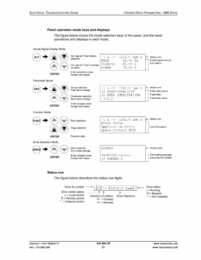
ELECTRICAL TROUBLESHOOTING GUIDE VIEWING DRIVE PARAMETERS - ABB DRIVE
CONTACT: 1-877-TESCO-77 EXI 600 HP WWW.TESCOCORP.COM
INTL: 713-359-7295 21 WWW.TESCOPARTS.COM

VIEWING DRIVE PARAMETERS - ABB DRIVE ELECTRICAL TROUBLESHOOTING GUIDE
CONTACT: 1-877-TESCO-77 EXI 600 HP WWW.TESCOCORP.COM
INTL: 713-359-7295 22 WWW.TESCOPARTS.COM

ELECTRICAL TROUBLESHOOTING GUIDE VIEWING DRIVE PARAMETERS - ABB DRIVE
CONTACT: 1-877-TESCO-77 EXI 600 HP WWW.TESCOCORP.COM
INTL: 713-359-7295 23 WWW.TESCOPARTS.COM
Displaying Signals
Selecting Actual Signals to Display
In the Actual Signal Display Mode, the user can:
• show three actual signals on the display at a time • select the actual signals to display • view the fault history • reset the fault history.
The panel enters the Actual Signal Display Mode when the user presses the ACT key, or if he/she does not press any key within one minute.

VIEWING DRIVE PARAMETERS - ABB DRIVE ELECTRICAL TROUBLESHOOTING GUIDE
CONTACT: 1-877-TESCO-77 EXI 600 HP WWW.TESCOCORP.COM
INTL: 713-359-7295 24 WWW.TESCOPARTS.COM
Displaying the Full Name of the Actual Signals
Viewing and Resetting Fault History
Attention! The fault history cannot be reset if there are active faults or warnings.

ELECTRICAL TROUBLESHOOTING GUIDE VIEWING DRIVE PARAMETERS - ABB DRIVE
CONTACT: 1-877-TESCO-77 EXI 600 HP WWW.TESCOCORP.COM
INTL: 713-359-7295 25 WWW.TESCOPARTS.COM
Displaying and Resetting Active Faults
Warning! If an external source for start command is selected and it is ON, the drive will start immediately after fault reset. If the cause of the fault has not been removed, the drive will trip again.
Fault History
The fault history restores information on the latest events (faults, warnings, and resets) of the drive. The table below shows how the events are stored in the fault history.
!

VIEWING DRIVE PARAMETERS - ABB DRIVE ELECTRICAL TROUBLESHOOTING GUIDE
CONTACT: 1-877-TESCO-77 EXI 600 HP WWW.TESCOCORP.COM
INTL: 713-359-7295 26 WWW.TESCOPARTS.COM
List of Tasks and Relevant ABB Drive Parameters

ELECTRICAL TROUBLESHOOTING GUIDE
CONTACT: 1-877-TESCO-77 EXI 600 HP WWW.TESCOCORP.COM
INTL: 713-359-7295 27 WWW.TESCOPARTS.COM
CHAPTER 7: VIEWING DRIVE PARAMETERS - OEM DRIVE
DRIVE SYSTEM DESCRIPTION
Overview
The TESCO EXI 600 Top Drive features WL600HP AC Vector motor and OEMV3000 Elec-tric Drive system. The nominal voltage for the drive system is 600VAC (60Hz) and can be supplied by either a self-contained generator or directly from the rig's AC bus.
The WL600HP motor is rated at 600HP (447kW) with 150% overload capability for 60 sec-onds. The maximum motor speed is 2,400 rpm. The motor produces 2,600 ft-lb of continuous torque within nominal speed range.
The stator windings have embedded RTDs to monitor motor temperature.
The OEMV3000 electric drive is of delta structure which is a modular solution with 3 modules (one rectifier and two inverter modules) required to run a 600HP top drive.
The EXI600 top drive system employs speed control with variable torque limits control scheme. The drive is controlled by a main PLC via RS485 serial communication. It receives START/STOP commands, speed reference, and torque limits from the PLC and at the same time sends back speed feedback, torque demand, and drive status to the PLC as well.
OEMV3000 is equipped with Drive Data Manager that allows full access and monitoring of drive parameters.
Drive Data Manager
The Drive Data Manager is a multi-purpose unit which provides keypad functions and has a 4-line, 20-digit display. It also includes four LEDs which indicate the status of the drive. The Drive Data Manager is mounted on the main panel inside the power building.
The Drive Data Manager functions include:
• setting and displaying drive parameters• monitoring drive status• displaying warnings and trips• maintaining track history

VIEWING DRIVE PARAMETERS - OEM DRIVE ELECTRICAL TROUBLESHOOTING GUIDE
CONTACT: 1-877-TESCO-77 EXI 600 HP WWW.TESCOCORP.COM
INTL: 713-359-7295 28 WWW.TESCOPARTS.COM
Fig-7-1(Illustration 1) shows the Drive Data Manager and describes the functions of indicators and keys.
Figure 7-1: Drive Data Manager & its keys and indicators functions

ELECTRICAL TROUBLESHOOTING GUIDE VIEWING DRIVE PARAMETERS - OEM DRIVE
CONTACT: 1-877-TESCO-77 EXI 600 HP WWW.TESCOCORP.COM
INTL: 713-359-7295 29 WWW.TESCOPARTS.COM
Navigating Menus and Parameters
Use the 4-way navigation key to browse through menus and parameters.
As an example, navigating Menu 1 is shown in Figure 7-2. Other menus are treated in exactly the same way.
Figure 7-2: Navigating Menu 1

VIEWING DRIVE PARAMETERS - OEM DRIVE ELECTRICAL TROUBLESHOOTING GUIDE
CONTACT: 1-877-TESCO-77 EXI 600 HP WWW.TESCOCORP.COM
INTL: 713-359-7295 30 WWW.TESCOPARTS.COM
Editing Parameters
Fig. 6-3 shows an example of editing parameter P2.00. Follow the same procedure to edit other parameters.
EXI 600 Drive System parameters are protected by a security code that prevents accidental editing. Only parameters of Menu 1, Menu 10 and Menu 27 are accessible for monitoring and display purpose. Parameters in these three menus are read-only. Menu 1 is configured to dis-play key parameters and status of the drive, Menu 10 is for warning and trip information, and Menu 27 is for history log.
Figure 7-3: Editing a Parameter
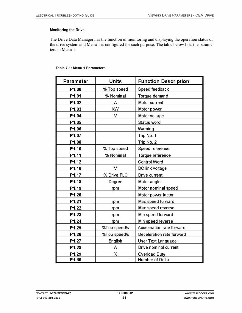
ELECTRICAL TROUBLESHOOTING GUIDE VIEWING DRIVE PARAMETERS - OEM DRIVE
CONTACT: 1-877-TESCO-77 EXI 600 HP WWW.TESCOCORP.COM
INTL: 713-359-7295 31 WWW.TESCOPARTS.COM
Monitoring the Drive
The Drive Data Manager has the function of monitoring and displaying the operation status of the drive system and Menu 1 is configured for such purpose. The table below lists the parame-ters in Menu 1.
Table 7-1: Menu 1 Parameters

VIEWING DRIVE PARAMETERS - OEM DRIVE ELECTRICAL TROUBLESHOOTING GUIDE
CONTACT: 1-877-TESCO-77 EXI 600 HP WWW.TESCOCORP.COM
INTL: 713-359-7295 32 WWW.TESCOPARTS.COM
History Log
OEMV3000 Drive allows for up to 10 variables to be recorded in 10 separate channels.
Each channel can store 100 samples maximum in chronological order.
History recording commences simultaneously with the drive start-up. Any trip will stop the history recording.
The recorded data can be displayed later to help diagnose faults. The 10 history channels are described in the following table.
Table 7-2: History Logs Channels
Variables History Channel
Motor Voltage (V) P27.01
Motor Current (A) P27.02
Torque demand (%) P27.03
Speed Ref (%) P27.04
Speed feedback (%) P27.05
DC voltage (V) P27.06
Temp. of output bridge 1 (°C) P27.07
Temp. of output bridge 2 (°C) P27.08
Max. CDC temperature* (°C) P27.09
Drive current (%) P27.10

ELECTRICAL TROUBLESHOOTING GUIDE
CONTACT: 1-877-TESCO-77 EXI 600 HP WWW.TESCOCORP.COM
INTL: 713-359-7295 33 WWW.TESCOPARTS.COM
CHAPTER 8: DRIVE SPECIFIC ISSUES
STARTING THE DRIVE:
1. Ensure the drillers panel is disabled (switch on the side).
2. Turn on all breakers in Panel Board 208V/120V.
3. Turn on MB2 (only if hydraulic oil heater is required), MB3 and MB4 in the 600V Control panel.
4. Make sure overloads 1M, 2M, 3M are not tripped (look at rectangular hole at top left of reset switch). If one is tripped turn the switch to the left to reset.
5. Charge the main 600V breaker by pumping on the handle until the indicator says the spring is charged.
6. Press the ON button.
7. The breaker will close and the indicator will display “ON”, at the same time the indicator for the spring will show “discharged”.
8. Open the panel door with the interface controller on it.
9. Close CB 1.
10. Close Fuses 7, 8, 9, 10.
11. At the driller’s panel the Green Ready Light and the Green Temp light now should be on.
12. Press the RESET button on the side of the driller's panel for 3 seconds.
13. Set the desired torques and speed with the set key on the side of the driller's panel as per TESCO EXI600 Operations Manual.
14. Press the RESET button on the side of the driller's panel for 3 seconds.
15. ENABLE the driller's panel.
16. The “Module ON” light should turn on.
17. Start drilling.

DRIVE SPECIFIC ISSUES ELECTRICAL TROUBLESHOOTING GUIDE
CONTACT: 1-877-TESCO-77 EXI 600 HP WWW.TESCOCORP.COM
INTL: 713-359-7295 34 WWW.TESCOPARTS.COM
TRACING FAULTS
ABB Drive
1. Make sure all breakers, overloads and fuses are still set and are good.
2. Move to the electronic interface panel mounted on the drive.
3. To see the faults use the procedure “Displaying and Resetting Active Faults” on page 25.Note: When a fault is detected, it is stored in the Fault History. The latest faults and warnings are stored together with the time stamp at which the event was detected.
Note: The fault logger collects 64 of the latest faults. When the drive power is switched off, 16 of the latest faults are stored.
Note: See original manufacturer’s ACS800 Drive Programming manual for more details.
Table 8-1: Main faults and their remedies
Faults Cause Action
ACS800 TEMP (4210)
A drive IGBT temperature increase. Trip limit is 100%.
• Check motor power. • Check flow of air and fan is working. • Check the environment condition
BC overheat (7114)
Brake Chopper overloaded • Check parameter setting of Group 27• Check the allowable limit of braking
cycle.• Check the AC supply Voltage, it should
be within limit
DC BUS LIM (3211)
Motor reaches torque limit due to intermediate DC.Voltage is too high or too low.
• Check Fault Function parameters
INV Disabled (3200)
When Inverter was stopped, optional DC switch is opened
• Close the switch and check fuse switch controller unit
INV OVERTEMP Converter temperature is beyond limit
• Check if ambient temperature has not exceeded 40ºC.
• Check inlet air filter.• Check if air circulation is proper. If not,
change or clean the heat sink
Motor STALL(7121)
Motor runs in Stall range due to either insufficient power or excessive load
• Check fault function parameters.• Check drive rating and motor load
DC OVERVOLT (3210)
Excessive intermediate circuit DC voltage.The trip limit for DC overvoltage is 1.3*U1Max, where U1Max is the main voltage range max value
• Check if parameter 20.05 is ON.• Check brake resistor (if used).• Check deceleration time.• Use coast to stop function.• Retrofit frequency converter with brake
chopper and brake resistor.

ELECTRICAL TROUBLESHOOTING GUIDE DRIVE SPECIFIC ISSUES
CONTACT: 1-877-TESCO-77 EXI 600 HP WWW.TESCOCORP.COM
INTL: 713-359-7295 35 WWW.TESCOPARTS.COM
DC UNDERVOLT (3220)
Insufficient intermediate DC Voltage.DC undervoltage trip limit= 0.6*U1Min, where U1Min is the main voltage range minimum value. For 400V & 500V, the U1Min is 380V.
• Check main supply and fuses. • Check for any bridge rectifier internal
fault.
MOTOR PHASE (FF56)
One of motor phases is missing • Check motor and motor cables.• Check thermal relay (if used).• Check Fault function parameter. Dis-
able this protection.
MOTOR TEMP (4310)
Motor temperature too high. • Check motor parameters and load.• Check start-up data.• Check Fault Function Data.
OVERCURRENT(2310)
Output current is exceeded. • Check motor load.• Check acceleration time.• Check encoder cable.• Check cable and motor.
OVER FREQ.(7123)
Motor runs faster than the highest speed limit.
• Check min/max. speed setting• Check if motor braking torque is ade-
quate.
SUPPLY PHASE(3130)
Intermediate circuit DC voltage is oscillating.
• Check main fuses.• Check for main supply imbalance.
UNDERLOAD (FF6A)
Motor load too low. • Check fault function parameter.
Table 8-1: Main faults and their remedies

DRIVE SPECIFIC ISSUES ELECTRICAL TROUBLESHOOTING GUIDE
CONTACT: 1-877-TESCO-77 EXI 600 HP WWW.TESCOCORP.COM
INTL: 713-359-7295 36 WWW.TESCOPARTS.COM
OEM Drive
1. First make sure all Breakers, Overloads, and Fuses are still set and are good. Then move to the electronic interface mounted on the drive.
2. Press the ESC button.
3. Press the arrow key until you find “MENU 1”.
4. Press ENTER. You will come to the first Parameter (referred to as P below).
5. Record all of the following values: Note: Readings with proper values for the top drive not rotating and Module ON light being on are shown in italic bold font below.
Note: To scroll to the next parameter i.e., from P01 to P02 press the arrow [ ]
6. If the unit has tripped, record the type of trip.
7. Then try to reset the trip by pressing the [?] button while looking at the live trip. This will bring up a menu with four items in it.
8. Press [#3] to attempt a reset.
9. If the reset works the trip will clear and you will be able to drill unless there are any other faults.
Table 8-2: Drive Parameters Readouts - Menu 1
Parameter # Description Value
P1 0.0 Speed Feed Back 0%
P1.01 Torque Demand 0%
P1.02 Motor Current 0 Amps
P1.03 Motor Power 0 KW
P1.04 Motor Volts 0 V
P1.05 Prog Status Word 0 04C2H
P1.06 Warning No 1 0
P1.07 Trip No 1 0
Table 8-3: Drive Parameters Readouts - cont.
Parameter # Description Value
P1.08 Trip No 2 0
P1.10 RS485 Reference 1 0%
P1.11 RS485 Ref 2 2.66%
P1.12 RS485 Control Word 0 0004H
P1.16 DC Link Voltage 825V
P1.17 Drive Current 0%
P1.18 Enc Angle 23.9º
P1.19 Motor Nom Speed 1174rpm
P1.20 Motor Power Factor .9

ELECTRICAL TROUBLESHOOTING GUIDE DRIVE SPECIFIC ISSUES
CONTACT: 1-877-TESCO-77 EXI 600 HP WWW.TESCOCORP.COM
INTL: 713-359-7295 37 WWW.TESCOPARTS.COM
10. Press the ESC button.
11. Press the arrow key until you find “MENU 10”.
12. Press ENTER which will bring you to the first Parameter (referred to as P below) of this menu.
13. Record all of the following values: Note: Readings with proper values for the Top Drive not rotating and Module ON light being on are shown in italic bold font below.
Note: To scroll to the next parameter i.e. from P10.01 to P10.02 hit the arrow [ ]
P1.21 Maximum Speed Forward 2192
P1.22 Maximum Speed Reverse 2192
P1.23 Minimum Speed Forward 0
P1.24 Minimum Speed Reverse 0
P1.25 Acceleration Rate Forward 20%/sec
P1.26 Deceleration Rate Reverse 30%/sec
P1.27 User Text Language 1
P1.28 Drive Nom Current 600A
P1.29 Overload duty 0150% O/Load
P1.30 No of Deltas 2
Table 8-4: Drive Parameters Readouts - Menu 10
Parameter # Description Value
P10.00 Warning No
P10.01 Warning No 2
P10.02 Warning No 3
P10.03 Warning No 4
P10.04 Warning No 5
P10.05 Warning No 6
P10.06 Warning No 7
P10.07 Warning No 8
P10.08 Warning No 9
P10.09 Warning No 10
P10.10 Trip No 1
P10.11 Trip No 2
P10.12 Trip No 3
P10.13 Trip No 4
P10.14 Trip No 5
Table 8-3: Drive Parameters Readouts - cont.

DRIVE SPECIFIC ISSUES ELECTRICAL TROUBLESHOOTING GUIDE
CONTACT: 1-877-TESCO-77 EXI 600 HP WWW.TESCOCORP.COM
INTL: 713-359-7295 38 WWW.TESCOPARTS.COM
14. Press the ESC button.
15. Press the arrow key until you find “MENU 11”.
16. Press ENTER which brings you to the first Parameter (referred to as P below) of this menu.
17. Record all of the following values: Note: Readings with proper values for the Top Drive not rotating and Module ON light being on are shown in italic bold font below.
Note: To scroll to the next parameter i.e. from P11.01 to P11.02 hit the arrow [ ]
Drive Stops After a Few Seconds Run
1. If the drive stops after a few seconds run and each time the delay time is different, check Drive Interlock at User I/O board terminal TB3-9 for interlocks.
2. Then see TB3-7 to find out if the robotic functions are running or not.
3. Refer to Electrical Schematics 98xxx118.
Drive Main Breaker Not Energizing
1. Check BFS and ESD relays. Both of these relays should be energized.
2. If BFS relay is not energized, check micro switches at each of the fuses inside the VFD.
3. If ESD relay is not energized, check ESD loop. Make sure E-stop PB at driller’s panel is not pushed.
4. Check Fuse F-8.
5. If everything is OK, check 24VDC across UV coil of MB1 breaker. If 24VDC is present then the UV coil is bad.
P10.15 Trip No 6
P10.16 Trip No 7
P10.17 Trip No 8
P10.18 Trip No 9
P10.19 Trip No 10
Table 8-5: Drive Parameters Readouts - Menu 11
Parameter # Description Value
P11.04 Electronic CDC Temperature
P11.05 IGBT 1 Temperature
P11.06 IGBT 2 Temperature
P11.08 Rectifier Temperature
P11.13 Max CDC Electronic Temp 47ºC
P11.14 Min CDC Electronic Temp 19ºC
Table 8-4: Drive Parameters Readouts - Menu 10

ELECTRICAL TROUBLESHOOTING GUIDE
CONTACT: 1-877-TESCO-77 EXI 600 HP WWW.TESCOCORP.COM
INTL: 713-359-7295 39 WWW.TESCOPARTS.COM
CHAPTER 9: PLC/DRIVE COMMUNICATION
RTU MASTER COMMUNICATION MODULE
HE693RTM705 Remote Terminal Unit provides the PLC (Series 90-30) with a flexible com-munication interface with RTU/Modbus network. It functions as a master that allows data to be read and/or written to one or more slave devices. It resides in a single local slot and is com-patible with the CPU331 or larger. In thios particular application it uses CPU363.
It provides two Modbus/RTU master channels which may be controlled by the 90-30 to access data from remote slave RTU's. Each channel can be individually programmed for dial in, dial out, radio modem, multi-drop (RS422/RS485), and direct connection (RS232) operation. Each channel can send or receive Analog or Discrete data using standard RTU commands (i.e. Read Coil). Multiple commands can be sent to each slave with each command requesting either a single point or multiple contiguous points of up to 250 bytes. Data to be sent or stored is placed in the 90-30 reference data tables. The tables define which RTU commands are sent to slave RTUs. Once started, the RTM705 uses these command lists to run in a semi-unsuper-vised state to transfer data between the 90-30 data tables and the slave RTUs.
The length of time between updates to each slave RTU can be individually adjusted. Each slave RTU has an individual status field, which reflects the condition of communications with that RTU. By continuously monitoring each status field, the 90-30 can detect configuration or communication problems on a slave by slave basis.

PLC/DRIVE COMMUNICATION ELECTRICAL TROUBLESHOOTING GUIDE
CONTACT: 1-877-TESCO-77 EXI 600 HP WWW.TESCOCORP.COM
INTL: 713-359-7295 40 WWW.TESCOPARTS.COM
PHYSICAL LAYOUT
The RTM705 module features three indicating LEDs: , (Port 1) and (Port 2).
At power-up, the light flashes to indicate that the module is cycling through its initial-
ization self-tests. Once the self-tests are complete, LED remains solidly lit. and
Ports lights become solidly lit after hardware initialization (refer to the figure below).
After the PLC ladder logic initializes a port with a COM_REQ, it checks for slaves. If the slave(s) is found and is working correctly, the LEDs go out, and during operation only flicker
with port activity. If a fatal error occurs, LED flashes an error code.
RTU/MODBUS PROTOCOL
The Modbus/RTU protocol uses a Master/Slave protocol that can support a common bus of one master and up to 247 Modbus Slaves. That common bus can be extended from direct wir-ing to radio and telephone modems. As an RTU master, commands are constructed and issued to an addressed slave. Only the addressed slave is expected to respond to the command. Mes-sage integrity is assured through use of checksums included in a message.
Initialization
Before the RTM can send acceptable RTU commands, it must be configured to the frame pro-tocol used by the slave RTU's. On power up, the RTM waits for an initialization through a COM_REQ before beginning to process RTU commands.
Before the COM_REQ can be issued, a pair of lists, SCB (Slave Control Block, 15 words, in this application it starts from R00701 to R00715) and MCB (Message Control Block, 6 words, in this application it starts from R00801 to R00806) must be preloaded in an appropriate PLC reference data table [%R, %AI, %AQ] with scanned information. These lists specify the Slaves, which are scanned and the RTU command(s) which are sent to the slave RTUs. Each
Figure 9-1: RTM705 Layout
OK P1 P2
OK
OK P1
P2
P1

ELECTRICAL TROUBLESHOOTING GUIDE PLC/DRIVE COMMUNICATION
CONTACT: 1-877-TESCO-77 EXI 600 HP WWW.TESCOCORP.COM
INTL: 713-359-7295 41 WWW.TESCOPARTS.COM
communication port requires its own set of lists and associated COM_REQ (17 words, in this application it starts from R00901 to R00917). A 5 seconds delay should be implemented in the ladder code before the COM_REQ is called.
There are three primary tasks to be performed by the PLC ladder logic: initialize the RTU Module, Read/write Modbus/RTU data and monitor communication status. For further details and other information refer to the User Manual.
Communication
With EXI600, the drive is controlled by PLC via RS485 serial communication. The drive com-municates with PLC using MODBUS RTU protocol. From the PLC it receives:
• RUN/STOP commands: when drive is ready, turn the switch away from neutral posi-tion, either to QUILL FWD or REV, to start the drive and the drive will stop once the switch is returned to neutral position
• Speed reference: SPEED INC(rease) & DEC(rease) switch generates speed refer-ence signal
• Torque limit: TORQUE INC(rease) & DEC(rease) Switch and at the same time sends back speed feedback, torque demand, and drive status to PLC as well.
The Drive status and communication with the PLC can be monitored via programmable status word (from drive to PLC) and control word (from PLC to drive). The following are control word & status words.
Table 9-1: BIT LAYOUT OF THE PROGRAMMABLE STATUS WORD 0
Bit 11-15
Bit 10 Bit 9 Bit 8 Bit 7 Bit 6 Bit 5 Bit 4 Bit 3 Bit 2 Bit 1 Bit 0
Spare Drive Ready
Encoder Bypass
Aux. Running
Inter-lock Zero Speed
REV Warning Drive Trip Drive Start
Drive Stop
Drive Running
Table 9-2: BIT LAYOUT OF RS485 CONTROL WORD 0
Bit 5-15 Bit 4 Bit 3 Bit 2 Bit 1 Bit 0
Spare Direction 1=REV Reset Trip ESD Stop Stop Drive Start Drive

PLC/DRIVE COMMUNICATION ELECTRICAL TROUBLESHOOTING GUIDE
CONTACT: 1-877-TESCO-77 EXI 600 HP WWW.TESCOCORP.COM
INTL: 713-359-7295 42 WWW.TESCOPARTS.COM
Common Faults
RTU Card Not Communicating.
If Green LED is not blinking it means RTU card is not communicating with the Drive. Reboot the PLC first, if it does not work then reboot both PLC and Drive.
Top Drive Not Turning After Selecting Direction, Torque, Speed
Check if there are any Trip/Warning indications at PLC Rack, SLOT 4 - You must have input A5 (ESD OK) and B4 (Chopper Module OK) illuminated to be able to drill.
If you have selected a direction, torque and speed and the top drive is not turning and you have no trips or warnings, make sure the pipe handler is “off” and check to see if the top drive blower motor and the drive blower motor are working.
If the top drive blower motor is working, check PLC SLOT 4 indicator B3. This should be illu-minated, if not check the pressure switch on the top drive.
Cimplicity Fault During Programming
If you uploaded a new program and the status bar of Cimplicity software shows a fault (a dia-mond with red F), try to Reset the fault from the table a few times, not only from I/O.
Slow Response to Commands
If commands are not reacting normally, check the resistance of the termination resistor. It should be between 100-110 Ohm. Replace the resistor if the value is not in range. A faulty resistor may also cause a loss of communication.
P2

ELECTRICAL TROUBLESHOOTING GUIDE
CONTACT: 1-877-TESCO-77 EXI 600 HP WWW.TESCOCORP.COM
INTL: 713-359-7295 43 WWW.TESCOPARTS.COM
CHAPTER 10: DRILLER’S PANEL
COMMON PROBLEMS
RTD Temperature
If the temperature of the motor windings (RTDs, one of the PLC inputs AI201, AI202 and AI203) exceeds 155°C, the “System Temperature” light on the driller's panel through output Q65 (LED A1 ON) will flash 3 times per second. If the temperature of the motor windings (RTDs, one of the PLC inputs AI201, AI202 and AI203) exceeds 175°C, the “System Temper-ature” light on the driller's panel through output Q65 (LED A1 ON) will turn off and the DRS Drive will shut down.
Drive Enable
When the ENABLE switch is in the ON position Input I89 (LED B09 ON) goes ‘HIGH’. The Drive Enable Command is sent to the Drive. When the ENABLE switch is in the OFF position input I89 (LED B09 OFF) becomes ‘LOW’. The Drive Disable Command is sent to the DRS Drive.
Drive Set
When the ENABLE switch is in the OFF position (Input I89, LED B09 OFF) and “Drive Set” key is held in the SET position (Input I91, LED B11 ON), then drive adjustment parameters can be altered.
Releasing “Drive Set” key will save the settings into PLC memory.
Note: top drive will not rotate if Drive Set parameters are not set to operating requirements or are set @ 0. Ensure you have sufficient Drive Set parameter range.
Drive Ready Light
After enabling the drive through PLC Input I89 (LED B09 ON), the drive performs its own system test. After successfully completing the test, the drive sends the signal (M00131) to PLC. After receiving that signal, PLC energizes “Ready Light” on the driller's panel through the output Q71 (LED A7 ON).

DRILLER’S PANEL ELECTRICAL TROUBLESHOOTING GUIDE
CONTACT: 1-877-TESCO-77 EXI 600 HP WWW.TESCOCORP.COM
INTL: 713-359-7295 44 WWW.TESCOPARTS.COM
Emergency Shut Down (E.S.D.)
When the red E.S.D. mushroom button on the driller's panel is pushed, it will trip the VFD cir-cuit breaker MB1 UV relay through PLC input I5 (LED A05 OFF). PLC stops functioning at the same time. In normal operating conditions the ESD light is ON.
When the red E.S.D. mushroom button on the power module wall is enabled, it will trip the Main Service Breaker UV relay, cutting the whole system off power.
Speed and Torque Limits
The EXI 600 Drive was designed to cope with 250 Ton 400 HP Top Drive performance curve.
Customers and operators have to ensure that set speed and torque limits do not exceed speci-fied limits. Life expectancy of the components and premature breakdown may result if the top drive is operated beyond specified capacity. Refer to Appendix-B for the performance curve.
Note: Always ensure Drive settings are not past peak output parameters to prevent top drive from exceeding its operating limits.
HOW TO CALIBRATE THE METERS ON THE DRILLER’S PANEL
The driller's panel contains four display meters:
• SET SPEED (rpm)• DELIVERED SPEED (rpm)• SET TORQUE (ft-lb)• DELIVERED TORQUE (ft-lb)
Use the following procedure to calibrate all meters before EVERY job. Recommended settings appear in the tables that follow the procedure. Although the values are different for each type of meter, calibrate all meters using the same procedure.
Figure 10-1: Example of the driller’s panel meter

ELECTRICAL TROUBLESHOOTING GUIDE DRILLER’S PANEL
CONTACT: 1-877-TESCO-77 EXI 600 HP WWW.TESCOCORP.COM
INTL: 713-359-7295 45 WWW.TESCOPARTS.COM
Setting LMD-120A meters
Caution: Ensure the quill is motionless whenever any meter adjust-ment work is being done.
Calibration
Although the values are different for each type of meter, you can calibrate all meters using the same procedure.
1. Meters are factory set for a 4-20mA signal.
2. Switch 1, 2, 3 control decimal points position.
Switch 4 adds dummy zero (5th digit, fixed zero) to extend range beyond +1999 to +19990.
Setting Decimal Point of the Meter
1. Stop quill rotation at the top drive.
2. Open the driller’s panel and access the meter.
3. The calibration controls are at the rear of the meter. To access them, remove the rear plug.
4. For the SET SPEED and DELIVERED SPEED meters:
This will display the rpm as a whole number without any decimal places.
Figure 10-2: LMD-120A gauge rear view
Switch Setting
1 0
2 0
3 0
4 0
!

DRILLER’S PANEL ELECTRICAL TROUBLESHOOTING GUIDE
CONTACT: 1-877-TESCO-77 EXI 600 HP WWW.TESCOCORP.COM
INTL: 713-359-7295 46 WWW.TESCOPARTS.COM
5. For the SET TORQUE and DELIVERED TORQUE meters:
This will display the torque values in thousands of foot-pounds. For example, a reading of 20.3 means 20,300 ft-lb.
6. Replace the plug.
7. Calibrate the zero and maximum values according to “Meter Calibration” on page 47.
Meter Settings
The following tables show the recommended settings for each of the meters on the driller's panel.
SET SPEED (rpm)
DELIVERED SPEED (rpm)
SET TORQUE
DELIVERED TORQUE
Switch Setting
1 0
2 0
3 1
4 0
Meter Option Settings
Signal4-12 mA12-20mA
4 mA =220 rpm; 12 mA = 0 rpm12 mA = 0 rpm; 20 mA = 220 rpm
Meter Option Settings
Signal4-12 mA12-20mA
4 mA = -220 rpm; 12 mA = 0 rpm12 mA = 0 rpm; 20 mA = 220 rpm
Meter Option Settings
Signal 4–20 mA 4 mA = 0; 20 mA = 45,000 lb ft
Meter Option Settings
Signal 4–20 mA 4 mA = 0; 20 mA = 45,000 lb ft

ELECTRICAL TROUBLESHOOTING GUIDE DRILLER’S PANEL
CONTACT: 1-877-TESCO-77 EXI 600 HP WWW.TESCOCORP.COM
INTL: 713-359-7295 47 WWW.TESCOPARTS.COM
Meter Calibration
Inspection Point Data/Notes
SET SPEED meter SET SPEED meter calibration: Set meter dip-switch setting to 0000 (verify with electrical
engineering department) Using loop calibrator, set ZERO ADJUST (zero) and SPAN
ADJUST (max) until meter displays the following values:4 mA = 0 rpm20 mA = 220 rpm Repeat ZERO ADJUST and SPAN ADJUST and adjust if
necessary Repeat ZERO ADJUST and SPAN ADJUST again and adjust if
necessary
DELIVERED SPEED meter DELIVERED SPEED meter calibration: Set meter dip-switch setting to 0000 (verify with electrical
engineering department) Using loop calibrator, adjust set ZERO ADJUST (zero) and SPAN
ADJUST (max) until meter displays the following values:4 mA = -220 rpm20 mA = 220 rpm Repeat ZERO ADJUST and SPAN ADJUST and adjust if
necessary Repeat ZERO ADJUST and SPAN ADJUST again and adjust if
necessary
SET TORQUE meter SET TORQUE meter calibration: Set meter dip-switch setting to 0010 (verify with electrical
engineering department) Using loop calibrator, set ZERO ADJUST (zero) and SPAN
ADJUST (max) until meter displays the following values:4 mA = 0 ft-lb20 mA = 45.0 (×1000) ft-lb Repeat ZERO ADJUST and SPAN ADJUST and adjust if
necessary Repeat ZERO ADJUST and SPAN ADJUST again and adjust if
necessary
DELIVERED TORQUE meter DELIVERED TORQUE meter calibration: Set meter dip-switch setting to 0010 (verify with electrical
engineering department) Using loop calibrator, set ZERO ADJUST (zero) and SPAN
ADJUST (max) until meter displays the following values:4 mA = 0 ft-lb20 mA = 45.0 (×1000) ft-lb Repeat ZERO ADJUST and SPAN ADJUST and adjust if
necessary Repeat ZERO ADJUST and SPAN ADJUST again and adjust if
necessary

DRILLER’S PANEL ELECTRICAL TROUBLESHOOTING GUIDE
CONTACT: 1-877-TESCO-77 EXI 600 HP WWW.TESCOCORP.COM
INTL: 713-359-7295 48 WWW.TESCOPARTS.COM
sabok
Intentionally Left Blank
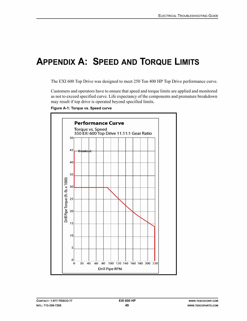
ELECTRICAL TROUBLESHOOTING GUIDE
CONTACT: 1-877-TESCO-77 EXI 600 HP WWW.TESCOCORP.COM
INTL: 713-359-7295 49 WWW.TESCOPARTS.COM
APPENDIX A: SPEED AND TORQUE LIMITS
The EXI 600 Top Drive was designed to meet 250 Ton 400 HP Top Drive performance curve.
Customers and operators have to ensure that speed and torque limits are applied and monitored as not to exceed specified curve. Life expectancy of the components and premature breakdown may result if top drive is operated beyond specified limits.
Figure A-1: Torque vs. Speed curve

SPEED AND TORQUE LIMITS ELECTRICAL TROUBLESHOOTING GUIDE
CONTACT: 1-877-TESCO-77 EXI 600 HP WWW.TESCOCORP.COM
INTL: 713-359-7295 50 WWW.TESCOPARTS.COM
sabok
Intentionally Left Blank

ELECTRICAL TROUBLESHOOTING GUIDE
CONTACT: 1-877-TESCO-77 EXI 600 HP WWW.TESCOCORP.COM
INTL: 713-359-7295 51 WWW.TESCOPARTS.COM
APPENDIX B: MAIN DIFFERENCES OVERVIEW, 50 HZ VS 60 HZ SPEC
Subject to the Customer requirements, EXI 600 Top Drive was designed to operate with either 60 or 50Hz Drive system. The main differences between the two are as follows:
600VAC 50 Hz MCC Panel
1. Both the Auxiliary pump and the blower motor are powered by VFD1 and VFD2 units and controlled via PLC control signals.
2. 12A and 8A Line reactors are used to supply the input voltage to VFD1 and to VFD2, powering the Blower motor and auxiliary pump drive motor respectively.Note: In 60 Hz configuration both Aux pump drive and blower motors are pow-ered via and 2M and 3M contactor and thermal overload.
3. Cooling fan is powered through an F1fuse, located in 120/208 VAC Power Distri-bution panel.
4. Green indicator light for Blower - ON signal is powered from VFD2 contacts 11&12 to TB3 contacts 2 & 8, all located in 600V/ AUX VFD Panel.
5. Both VFD1 (Auxiliary Hydraulic Pump motor) and VFD2 (Blower motor) are Normally Open contacts (terminals 11 - 12 and 24 - 25 respectively) and are used to supply input signals to the PLC Panel.
6. White indicator light for Main Power - ON signal is powered from TB-MPEM contacts 2&4 located in 600V/ AUX VFD Panel, to Receptacle 07, located in the waterfall panel.
Transformer
The dual-frequency 50Hz/60Hz transformer (15kVA, 600/120-208 VAC, 3Phase CE/CSA/UL) is used in 50 Hz spec system.
HVAC System
The 50 Hz system uses a 5-Ton, 208VAC, WA602-E09 unit.

MAIN DIFFERENCES OVERVIEW, 50 HZ VS 60 HZ SPEC ELECTRICAL TROUBLESHOOTING GUIDE
CONTACT: 1-877-TESCO-77 EXI 600 HP WWW.TESCOCORP.COM
INTL: 713-359-7295 52 WWW.TESCOPARTS.COM
sabok
Intentionally Left Blank

ELECTRICAL TROUBLESHOOTING GUIDE SCHEMATICS: BARD CHILLER
CONTACT: 1-877-TESCO-77 EXI 600 HP WWW.TESCOCORP.COM
INTL: 713-359-7295 53 WWW.TESCOPARTS.COM
APPENDIX C: SCHEMATICS: BARD CHILLER

SCHEMATICS: BARD CHILLER ELECTRICAL TROUBLESHOOTING GUIDE
CONTACT: 1-877-TESCO-77 EXI 600 HP WWW.TESCOCORP.COM
INTL: 713-359-7295 54 WWW.TESCOPARTS.COM
sabok
Intentionally Left Blank

ELECTRICAL TROUBLESHOOTING GUIDE
CONTACT: 1-877-TESCO-77 EXI 600 HP WWW.TESCOCORP.COM
INTL: 713-359-7295 55 WWW.TESCOPARTS.COM
ENGINEERING SIGN-OFF
This sign-off sheet indicates that this document has been approved for release by the Engineering Department at TESCO.
Document Complete By Signature Date Signed
Document Reviewed/Approved Date Signed
madejskm
Typewritten Text
April 9, 2009
ELECTRICAL TROUBLESHOOTING GUIDE
CONTACT: 1-877-TESCO-77 EXI 600 HP WWW.TESCOCORP.COM
INTL: 713-359-7295 56 WWW.TESCOPARTS.COM

DOCUMENT NAME: 880081 REV 0
List of Parts and Assemblies
EXI 600 Top Drive System
400TON EXI 600HP/60Hz
Unit 871


LIST OF PARTS AND ASSEMBLIES EXI-600 TOP DRIVE SYSTEM
CONTACT: 1-877-TESCO-77 I WWW.TESCOCORP.COM
INTL: 713-359-7295 WWW.TESCOPARTS.COM
Tesco Corporation ("TESCO") has made every effort to ensure that this document contains accurate and current information for the TESCO top drive, however, the document is intended to be used in conjunction with a complete training program and on-site supervision and TESCO does not warrant or guarantee that the information contained herein is either complete or accurate in every respect, and the reader hereby protects, indemnifies and holds harmless Tesco Corporation together with its directors, officers, employees and agents from and against all liability for personal injury, death or property damage to any person arising directly or indirectly from the use by the reader of the information contained in the document.
This equipment was filled at the factory with TESCO ULTREX™ brand fluids and greases. To ensure maximum performance and to avoid cross-contamination, we strongly recommend the continued usage of TESCO ULTREX™ lubricants, unless otherwise specified.
TESCO ULTREX™ is a trademark and TESCO® is a registered trademark of Tesco Corporation.
Tesco Corporation © 2010
Contact Information
Corporate Head Office3993 W. Sam Houston Parkway N., Suite 100
Houston, Texas, 77043USA
www.tescocorp.comwww.tescoparts.com
Telephone: (713) 359-7000Fax: (713) 359-7001
After Market Sales and Service ContactToll Free North America: 1-877-TESCO-77
International: 713-359-7295
EXI-600 TOP DRIVE SYSTEM LIST OF PARTS AND ASSEMBLIES
CONTACT: 1-877-TESCO-77 II WWW.TESCOCORP.COM
INTL: 713-359-7295 WWW.TESCOPARTS.COM
Revision Information
Version Date Description of Changes
Rev 0 August 2010 First release of the EXI parts lists, Unit 871

LIST OF PARTS AND ASSEMBLIES EXI-600 TOP DRIVE SYSTEM
CONTACT: 1-877-TESCO-77 III WWW.TESCOCORP.COM
INTL: 713-359-7295 WWW.TESCOPARTS.COM
TABLE OF CONTENTS
About This Document . . . . . . . . . . . . . . . . . . . . . . . . . . . . . . . . . . . . . Section 1
Top Drive. . . . . . . . . . . . . . . . . . . . . . . . . . . . . . . . . . . . . . . . . . . . . . . . Section 2

EXI-600 TOP DRIVE SYSTEM LIST OF PARTS AND ASSEMBLIES
CONTACT: 1-877-TESCO-77 IV WWW.TESCOCORP.COM
INTL: 713-359-7295 WWW.TESCOPARTS.COM
This page has been left blank intentionally.

LIST OF PARTS AND ASSEMBLIES EXI-600 TOP DRIVE SYSTEM
CONTACT: 1-877-TESCO-77 WWW.TESCOCORP.COM
INTL: 713-359-7295 WWW.TESCOPARTS.COM
SECTION 1: ABOUT THIS DOCUMENT
This chapter contains all the parts lists and the accompanying illustrations for the 400TON EXI 600HP/60Hz top drive system.
The illustrations are drawn from the off driller’s side point of view.
Table 1-1: Where to Find More Information
For information on Refer to
system components overview System Description
• installation• rig up• commissioning• pre-operational checklists• rig out procedures
Installation Guide
• setting torque and speed• driller's panel functions and operating descriptions• making connections• drilling ahead• tripping• freeing stuck pipe
Operations Guide
• load path inspections• maintenance/service schedules• component disassembly and reassembly
Maintenance Guide
TESCO manufactured parts and part numbers Parts List
troubleshooting Troubleshooting Guide (where available)
• electrical schematics• hydraulic schematics• gearbox lubrication schematics
System schematics
available options and spares TESCO Representative

EXI-600 TOP DRIVE SYSTEM LIST OF PARTS AND ASSEMBLIES
CONTACT: 1-877-TESCO-77 WWW.TESCOCORP.COM
INTL: 713-359-7295 WWW.TESCOPARTS.COM
This page has been left blank intentionally.
LIST OF PARTS AND ASSEMBLIES EXI-600 TOP DRIVE SYSTEM
CONTACT: 1-877-TESCO-77 WWW.TESCOCORP.COM
INTL: 713-359-7295 WWW.TESCOPARTS.COM
SECTION 2: TOP DRIVE

EXI-600 TOP DRIVE SYSTEM LIST OF PARTS AND ASSEMBLIES
CONTACT: 1-877-TESCO-77 WWW.TESCOCORP.COM
INTL: 713-359-7295 WWW.TESCOPARTS.COM
This page has been left blank intentionally.
EXI600 TOP DRIVE, PART NUMBER 5001927 LIST OF PARTS AND ASSEMBLIES
CONTACT: 1-877-TESCO-77 2-1 WWW.TESCOCORP.COMINTL: 713-359-7295 WWW.TESCOPARTS.COM
EXI600 TOP DRIVE, PART NUMBER 5001927
This chapter contains all the parts lists and the accompanying illustrations for the EXI600 Top Drive, Part Number 5001927.
Revision Information
Document Number: PL-5001927
Rev Date Description of Changes
0 Aug 2010 Initial release of manual for EXI600 Top Drive, Part Number 5001927

EXI600 TOP DRIVE, PART NUMBER 5001927 LIST OF PARTS AND ASSEMBLIES
CONTACT: 1-877-TESCO-77 2-2 WWW.TESCOCORP.COMINTL: 713-359-7295 WWW.TESCOPARTS.COM
This page has been left blank intentionally.

LIST OF PARTS AND ASSEMBLIES EXI600 TOP DRIVE, PART NUMBER 1120384
CONTACT: 1-877-TESCO-77 2-3 WWW.TESCOCORP.COMINTL: 713-359-7295 WWW.TESCOPARTS.COM
TABLE OF CONTENTS
EXI600 Top Drive, Part Number 5001927 . . . . . . . . . . . . . . . . . . . . . . . . . . . . . . . . . . . . . 2- 1Top Drive, 11.11:1 Ratio, w/o Swivel Yoke, 600V Blower Motor, 400-EXI-600 . . . . . . . . . . . . . . . 2- 4Manifold/Enclosure Assy, Mechanical, 10-Station, 350-EXI-600. . . . . . . . . . . . . . . . . . . . . . . . . 2- 20Manifold Body, Assembly, 10-Station, 350-EXI-600 . . . . . . . . . . . . . . . . . . . . . . . . . . . . . . . . . . . 2- 22Manifold Assembly, Grabber Lift, EXI/HXI . . . . . . . . . . . . . . . . . . . . . . . . . . . . . . . . . . . . . . . . . . 2- 24Kit, Lube System, 350-EXI-600, Ensign USA . . . . . . . . . . . . . . . . . . . . . . . . . . . . . . . . . . . . . . . . 2- 26Kit, Bonnet/Goosneck/Washpipe Installation, 400-EXI-600, Ensign USA . . . . . . . . . . . . . . . . . 2- 30Assembly, Washpipe, 7500-psi, EMI400/EMI450/EXI/HXI . . . . . . . . . . . . . . . . . . . . . . . . . . . . . . 2- 32Kit, Yoke/Link/Counterbalance System Instl, 400-EXI-600, Ensign USA . . . . . . . . . . . . . . . . . . 2- 34Gearbox, 11.11:1 Ratio, 350-EXI-600 . . . . . . . . . . . . . . . . . . . . . . . . . . . . . . . . . . . . . . . . . . . . . . . 2- 38Motor Assembly, Pipe Handler Rotation, 350-EXI-600. . . . . . . . . . . . . . . . . . . . . . . . . . . . . . . . . 2- 42Kit, Lock, Pipe Handler, 350-EXI-600 . . . . . . . . . . . . . . . . . . . . . . . . . . . . . . . . . . . . . . . . . . . . . . . 2- 44Kit, Main Motor Installation, w/600V Blower Motor, 350-EXI-600 . . . . . . . . . . . . . . . . . . . . . . . . 2- 48Kit, Pipe Handler, 350-EXI-600 . . . . . . . . . . . . . . . . . . . . . . . . . . . . . . . . . . . . . . . . . . . . . . . . . . . . 2- 50Collar, Load, 350-EXI-600 . . . . . . . . . . . . . . . . . . . . . . . . . . . . . . . . . . . . . . . . . . . . . . . . . . . . . . . . 2- 52Kit, Nut, Load, 350/400-EXI-600 . . . . . . . . . . . . . . . . . . . . . . . . . . . . . . . . . . . . . . . . . . . . . . . . . . . 2- 54Kit, Link Tilt, 350-EXI-600 . . . . . . . . . . . . . . . . . . . . . . . . . . . . . . . . . . . . . . . . . . . . . . . . . . . . . . . . 2- 56Kit, Mudsaver Valve Installation, 350-EXI-600 . . . . . . . . . . . . . . . . . . . . . . . . . . . . . . . . . . . . . . . 2- 58Clamp Assembly, Connection Lock, 7-7/8” . . . . . . . . . . . . . . . . . . . . . . . . . . . . . . . . . . . . . . . . . 2- 60Kit, Grabber Leg Assembly, 350-EXI-600 . . . . . . . . . . . . . . . . . . . . . . . . . . . . . . . . . . . . . . . . . . . 2- 62Grabber, 9”. . . . . . . . . . . . . . . . . . . . . . . . . . . . . . . . . . . . . . . . . . . . . . . . . . . . . . . . . . . . . . . . . . . . 2- 64Piston/Cylinder Assembly, Grabber . . . . . . . . . . . . . . . . . . . . . . . . . . . . . . . . . . . . . . . . . . . . . . . 2- 66Kit, Torque Arrest, 350-EXI-600, Ensign USA . . . . . . . . . . . . . . . . . . . . . . . . . . . . . . . . . . . . . . . . 2- 68Manifold/Enclosure Assembly, 10-Station, 350-EXI-600 . . . . . . . . . . . . . . . . . . . . . . . . . . . . . . . 2- 70Assembly, Mount, Service Loop, 350-EXI-600, Ensign USA . . . . . . . . . . . . . . . . . . . . . . . . . . . . 2- 72Assembly, Torque Restraint, 350-EXI-600, Ensign USA . . . . . . . . . . . . . . . . . . . . . . . . . . . . . . . 2- 74

EXI600 TOP DRIVE, PART NUMBER 5001927 LIST OF PARTS AND ASSEMBLIES
CONTACT: 1-877-TESCO-77 2-4 WWW.TESCOCORP.COMINTL: 713-359-7295 WWW.TESCOPARTS.COM
TOP DRIVE, 11.11:1 RATIO, W/O SWIVEL YOKE, 600V BLOWER MOTOR, 400-EXI-600

LIST OF PARTS AND ASSEMBLIES EXI600 TOP DRIVE, PART NUMBER 5001927
CONTACT: 1-877-TESCO-77 2-5 WWW.TESCOCORP.COMINTL: 713-359-7295 WWW.TESCOPARTS.COM

EXI600 TOP DRIVE, PART NUMBER 5001927 LIST OF PARTS AND ASSEMBLIES
CONTACT: 1-877-TESCO-77 2-6 WWW.TESCOCORP.COMINTL: 713-359-7295 WWW.TESCOPARTS.COM
KIT, AUXILIARY HYDRAULICS, SIDE MOUNT, 350-EXI-600, ENSIGN USA

LIST OF PARTS AND ASSEMBLIES EXI600 TOP DRIVE, PART NUMBER 5001927
CONTACT: 1-877-TESCO-77 2-7 WWW.TESCOCORP.COMINTL: 713-359-7295 WWW.TESCOPARTS.COM

EXI600 TOP DRIVE, PART NUMBER 5001927 LIST OF PARTS AND ASSEMBLIES
CONTACT: 1-877-TESCO-77 2-8 WWW.TESCOCORP.COMINTL: 713-359-7295 WWW.TESCOPARTS.COM

LIST OF PARTS AND ASSEMBLIES EXI600 TOP DRIVE, PART NUMBER 5001927
CONTACT: 1-877-TESCO-77 2-9 WWW.TESCOCORP.COMINTL: 713-359-7295 WWW.TESCOPARTS.COM
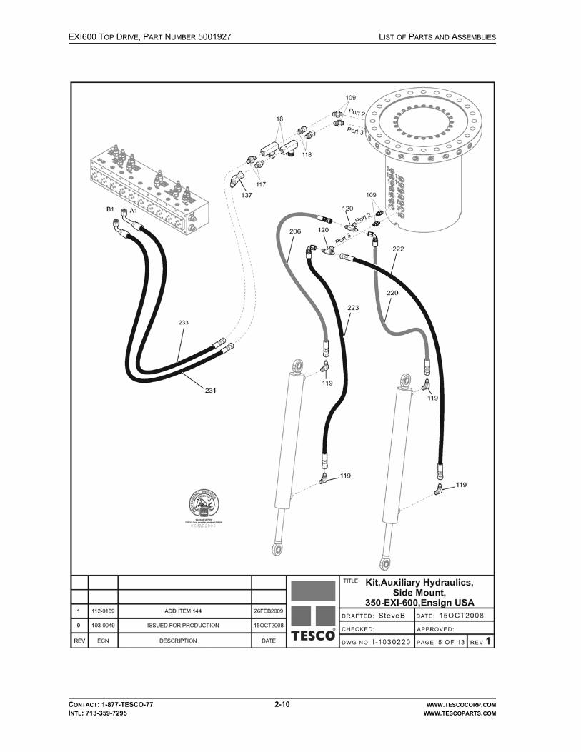
EXI600 TOP DRIVE, PART NUMBER 5001927 LIST OF PARTS AND ASSEMBLIES
CONTACT: 1-877-TESCO-77 2-10 WWW.TESCOCORP.COMINTL: 713-359-7295 WWW.TESCOPARTS.COM
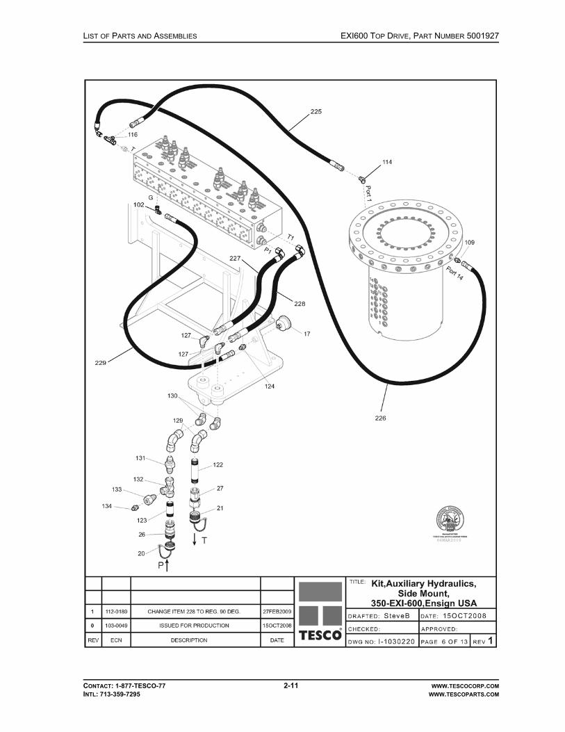
LIST OF PARTS AND ASSEMBLIES EXI600 TOP DRIVE, PART NUMBER 5001927
CONTACT: 1-877-TESCO-77 2-11 WWW.TESCOCORP.COMINTL: 713-359-7295 WWW.TESCOPARTS.COM

EXI600 TOP DRIVE, PART NUMBER 5001927 LIST OF PARTS AND ASSEMBLIES
CONTACT: 1-877-TESCO-77 2-12 WWW.TESCOCORP.COMINTL: 713-359-7295 WWW.TESCOPARTS.COM
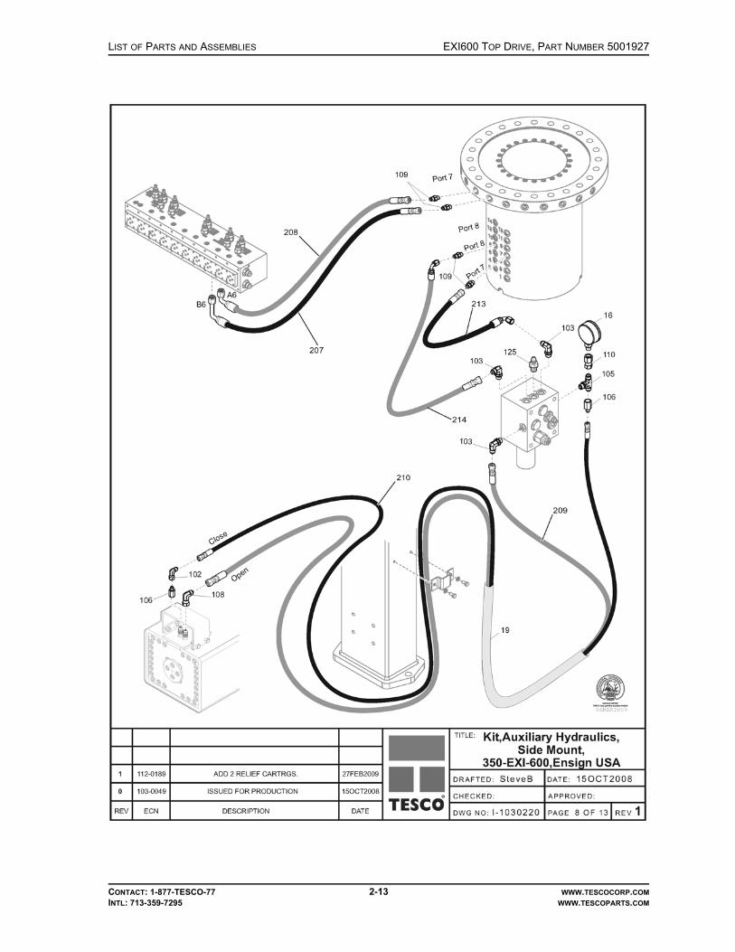
LIST OF PARTS AND ASSEMBLIES EXI600 TOP DRIVE, PART NUMBER 5001927
CONTACT: 1-877-TESCO-77 2-13 WWW.TESCOCORP.COMINTL: 713-359-7295 WWW.TESCOPARTS.COM

EXI600 TOP DRIVE, PART NUMBER 5001927 LIST OF PARTS AND ASSEMBLIES
CONTACT: 1-877-TESCO-77 2-14 WWW.TESCOCORP.COMINTL: 713-359-7295 WWW.TESCOPARTS.COM

LIST OF PARTS AND ASSEMBLIES EXI600 TOP DRIVE, PART NUMBER 5001927
CONTACT: 1-877-TESCO-77 2-15 WWW.TESCOCORP.COMINTL: 713-359-7295 WWW.TESCOPARTS.COM

EXI600 TOP DRIVE, PART NUMBER 5001927 LIST OF PARTS AND ASSEMBLIES
CONTACT: 1-877-TESCO-77 2-16 WWW.TESCOCORP.COMINTL: 713-359-7295 WWW.TESCOPARTS.COM

LIST OF PARTS AND ASSEMBLIES EXI600 TOP DRIVE, PART NUMBER 5001927
CONTACT: 1-877-TESCO-77 2-17 WWW.TESCOCORP.COMINTL: 713-359-7295 WWW.TESCOPARTS.COM
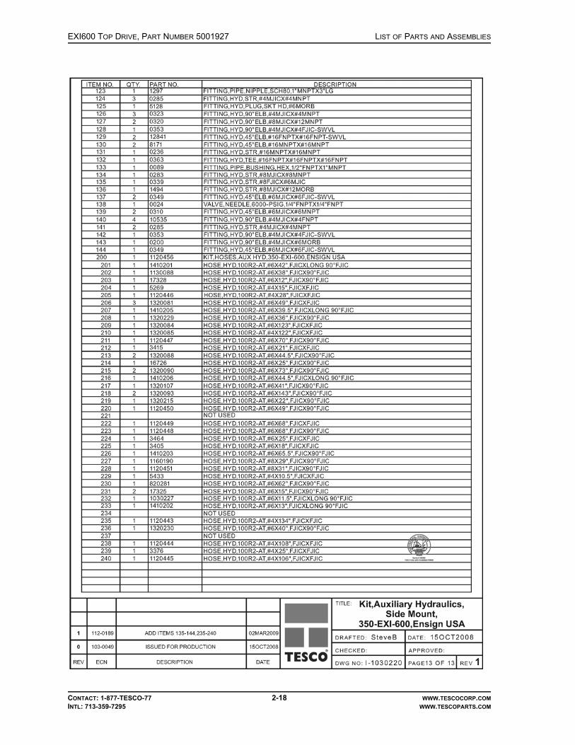
EXI600 TOP DRIVE, PART NUMBER 5001927 LIST OF PARTS AND ASSEMBLIES
CONTACT: 1-877-TESCO-77 2-18 WWW.TESCOCORP.COMINTL: 713-359-7295 WWW.TESCOPARTS.COM

LIST OF PARTS AND ASSEMBLIES EXI600 TOP DRIVE, PART NUMBER 5001927
CONTACT: 1-877-TESCO-77 2-19 WWW.TESCOCORP.COMINTL: 713-359-7295 WWW.TESCOPARTS.COM
This page has been left blank intentionally.

EXI600 TOP DRIVE, PART NUMBER 5001927 LIST OF PARTS AND ASSEMBLIES
CONTACT: 1-877-TESCO-77 2-20 WWW.TESCOCORP.COMINTL: 713-359-7295 WWW.TESCOPARTS.COM
MANIFOLD/ENCLOSURE ASSY, MECHANICAL, 10-STATION, 350-EXI-600

LIST OF PARTS AND ASSEMBLIES EXI600 TOP DRIVE, PART NUMBER 5001927
CONTACT: 1-877-TESCO-77 2-21 WWW.TESCOCORP.COMINTL: 713-359-7295 WWW.TESCOPARTS.COM
This page has been left blank intentionally.

EXI600 TOP DRIVE, PART NUMBER 5001927 LIST OF PARTS AND ASSEMBLIES
CONTACT: 1-877-TESCO-77 2-22 WWW.TESCOCORP.COMINTL: 713-359-7295 WWW.TESCOPARTS.COM
MANIFOLD BODY, ASSEMBLY, 10-STATION, 350-EXI-600

LIST OF PARTS AND ASSEMBLIES EXI600 TOP DRIVE, PART NUMBER 5001927
CONTACT: 1-877-TESCO-77 2-23 WWW.TESCOCORP.COMINTL: 713-359-7295 WWW.TESCOPARTS.COM

EXI600 TOP DRIVE, PART NUMBER 5001927 LIST OF PARTS AND ASSEMBLIES
©TESCO CORPORATION, 20102-24
MANIFOLD ASSEMBLY, GRABBER LIFT, EXI/HXI

LIST OF PARTS AND ASSEMBLIES EXI600 TOP DRIVE, PART NUMBER 5001927
CONTACT: 1-877-TESCO-77 2-25 WWW.TESCOCORP.COMINTL: 713-359-7295 WWW.TESCOPARTS.COM
This page has been left blank intentionally.

EXI600 TOP DRIVE, PART NUMBER 5001927 LIST OF PARTS AND ASSEMBLIES
CONTACT: 1-877-TESCO-77 2-26 WWW.TESCOCORP.COMINTL: 713-359-7295 WWW.TESCOPARTS.COM
KIT, LUBE SYSTEM, 350-EXI-600, ENSIGN USA

LIST OF PARTS AND ASSEMBLIES EXI600 TOP DRIVE, PART NUMBER 5001927
CONTACT: 1-877-TESCO-77 2-27 WWW.TESCOCORP.COMINTL: 713-359-7295 WWW.TESCOPARTS.COM

EXI600 TOP DRIVE, PART NUMBER 5001927 LIST OF PARTS AND ASSEMBLIES
CONTACT: 1-877-TESCO-77 2-28 WWW.TESCOCORP.COMINTL: 713-359-7295 WWW.TESCOPARTS.COM

LIST OF PARTS AND ASSEMBLIES EXI600 TOP DRIVE, PART NUMBER 5001927
CONTACT: 1-877-TESCO-77 2-29 WWW.TESCOCORP.COMINTL: 713-359-7295 WWW.TESCOPARTS.COM
This page has been left blank intentionally.

EXI600 TOP DRIVE, PART NUMBER 5001927 LIST OF PARTS AND ASSEMBLIES
CONTACT: 1-877-TESCO-77 2-30 WWW.TESCOCORP.COMINTL: 713-359-7295 WWW.TESCOPARTS.COM
KIT, BONNET/GOOSNECK/WASHPIPE INSTALLATION, 400-EXI-600, ENSIGN USA
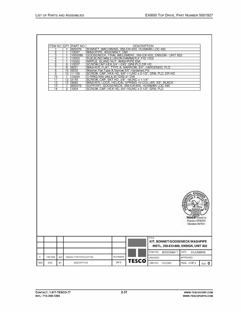
LIST OF PARTS AND ASSEMBLIES EXI600 TOP DRIVE, PART NUMBER 5001927
CONTACT: 1-877-TESCO-77 2-31 WWW.TESCOCORP.COMINTL: 713-359-7295 WWW.TESCOPARTS.COM

EXI600 TOP DRIVE, PART NUMBER 5001927 LIST OF PARTS AND ASSEMBLIES
CONTACT: 1-877-TESCO-77 2-32 WWW.TESCOCORP.COMINTL: 713-359-7295 WWW.TESCOPARTS.COM
ASSEMBLY, WASHPIPE, 7500-PSI, EMI400/EMI450/EXI/HXI
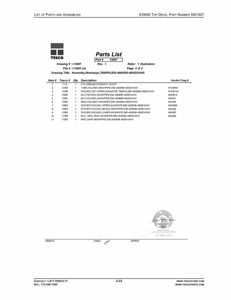
LIST OF PARTS AND ASSEMBLIES EXI600 TOP DRIVE, PART NUMBER 5001927
CONTACT: 1-877-TESCO-77 2-33 WWW.TESCOCORP.COMINTL: 713-359-7295 WWW.TESCOPARTS.COM

EXI600 TOP DRIVE, PART NUMBER 5001927 LIST OF PARTS AND ASSEMBLIES
CONTACT: 1-877-TESCO-77 2-34 WWW.TESCOCORP.COMINTL: 713-359-7295 WWW.TESCOPARTS.COM
KIT, YOKE/LINK/COUNTERBALANCE SYSTEM INSTL, 400-EXI-600, ENSIGN USA

LIST OF PARTS AND ASSEMBLIES EXI600 TOP DRIVE, PART NUMBER 5001927
CONTACT: 1-877-TESCO-77 2-35 WWW.TESCOCORP.COMINTL: 713-359-7295 WWW.TESCOPARTS.COM

EXI600 TOP DRIVE, PART NUMBER 5001927 LIST OF PARTS AND ASSEMBLIES
CONTACT: 1-877-TESCO-77 2-36 WWW.TESCOCORP.COMINTL: 713-359-7295 WWW.TESCOPARTS.COM

LIST OF PARTS AND ASSEMBLIES EXI600 TOP DRIVE, PART NUMBER 5001927
CONTACT: 1-877-TESCO-77 2-37 WWW.TESCOCORP.COMINTL: 713-359-7295 WWW.TESCOPARTS.COM
This page has been left blank intentionally.

EXI600 TOP DRIVE, PART NUMBER 5001927 LIST OF PARTS AND ASSEMBLIES
CONTACT: 1-877-TESCO-77 2-38 WWW.TESCOCORP.COMINTL: 713-359-7295 WWW.TESCOPARTS.COM
GEARBOX, 11.11:1 RATIO, 350-EXI-600

LIST OF PARTS AND ASSEMBLIES EXI600 TOP DRIVE, PART NUMBER 5001927
CONTACT: 1-877-TESCO-77 2-39 WWW.TESCOCORP.COMINTL: 713-359-7295 WWW.TESCOPARTS.COM
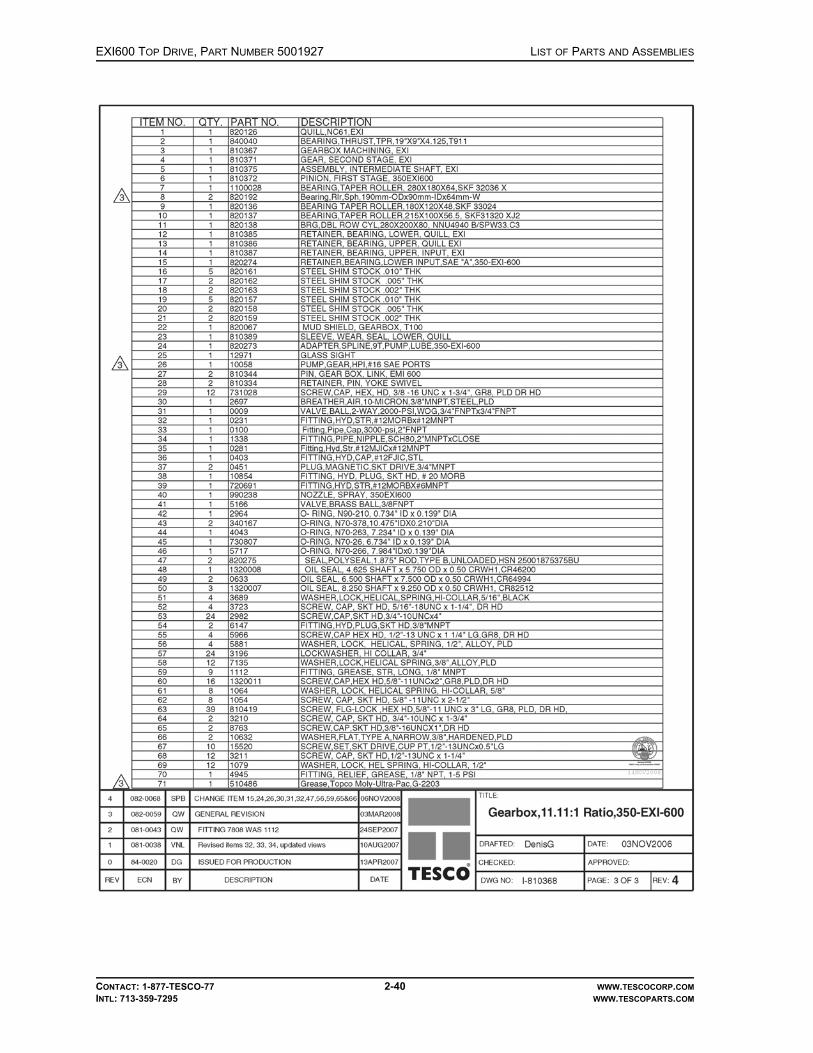
EXI600 TOP DRIVE, PART NUMBER 5001927 LIST OF PARTS AND ASSEMBLIES
CONTACT: 1-877-TESCO-77 2-40 WWW.TESCOCORP.COMINTL: 713-359-7295 WWW.TESCOPARTS.COM

LIST OF PARTS AND ASSEMBLIES EXI600 TOP DRIVE, PART NUMBER 5001927
CONTACT: 1-877-TESCO-77 2-41 WWW.TESCOCORP.COMINTL: 713-359-7295 WWW.TESCOPARTS.COM
This page has been left blank intentionally.

EXI600 TOP DRIVE, PART NUMBER 5001927 LIST OF PARTS AND ASSEMBLIES
CONTACT: 1-877-TESCO-77 2-42 WWW.TESCOCORP.COMINTL: 713-359-7295 WWW.TESCOPARTS.COM
MOTOR ASSEMBLY, PIPE HANDLER ROTATION, 350-EXI-600

LIST OF PARTS AND ASSEMBLIES EXI600 TOP DRIVE, PART NUMBER 5001927
CONTACT: 1-877-TESCO-77 2-43 WWW.TESCOCORP.COMINTL: 713-359-7295 WWW.TESCOPARTS.COM
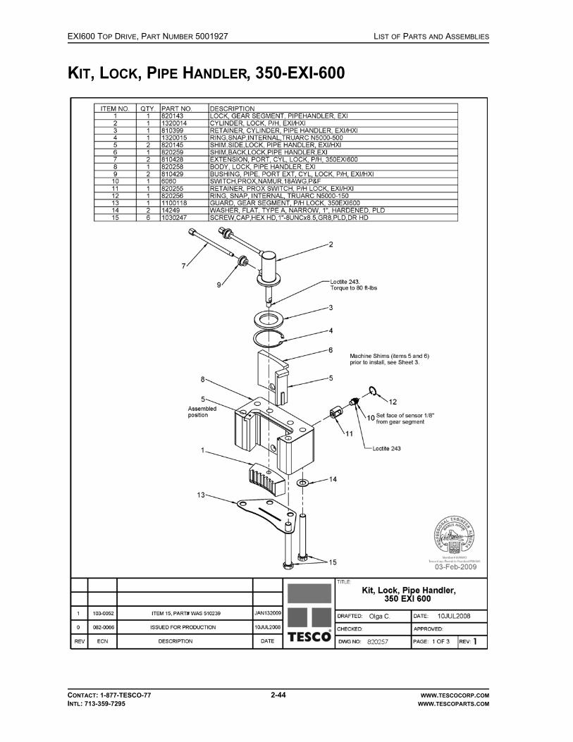
EXI600 TOP DRIVE, PART NUMBER 5001927 LIST OF PARTS AND ASSEMBLIES
CONTACT: 1-877-TESCO-77 2-44 WWW.TESCOCORP.COMINTL: 713-359-7295 WWW.TESCOPARTS.COM
KIT, LOCK, PIPE HANDLER, 350-EXI-600

LIST OF PARTS AND ASSEMBLIES EXI600 TOP DRIVE, PART NUMBER 5001927
CONTACT: 1-877-TESCO-77 2-45 WWW.TESCOCORP.COMINTL: 713-359-7295 WWW.TESCOPARTS.COM
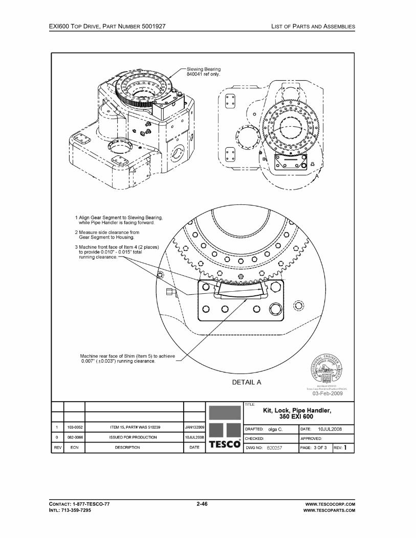
EXI600 TOP DRIVE, PART NUMBER 5001927 LIST OF PARTS AND ASSEMBLIES
CONTACT: 1-877-TESCO-77 2-46 WWW.TESCOCORP.COMINTL: 713-359-7295 WWW.TESCOPARTS.COM

LIST OF PARTS AND ASSEMBLIES EXI600 TOP DRIVE, PART NUMBER 5001927
CONTACT: 1-877-TESCO-77 2-47 WWW.TESCOCORP.COMINTL: 713-359-7295 WWW.TESCOPARTS.COM
This page has been left blank intentionally.

EXI600 TOP DRIVE, PART NUMBER 5001927 LIST OF PARTS AND ASSEMBLIES
CONTACT: 1-877-TESCO-77 2-48 WWW.TESCOCORP.COMINTL: 713-359-7295 WWW.TESCOPARTS.COM
KIT, MAIN MOTOR INSTALLATION, W/600V BLOWER MOTOR, 350-EXI-600

LIST OF PARTS AND ASSEMBLIES EXI600 TOP DRIVE, PART NUMBER 5001927
CONTACT: 1-877-TESCO-77 2-49 WWW.TESCOCORP.COMINTL: 713-359-7295 WWW.TESCOPARTS.COM
This page has been left blank intentionally.

EXI600 TOP DRIVE, PART NUMBER 5001927 LIST OF PARTS AND ASSEMBLIES
CONTACT: 1-877-TESCO-77 2-50 WWW.TESCOCORP.COMINTL: 713-359-7295 WWW.TESCOPARTS.COM
KIT, PIPE HANDLER, 350-EXI-600

LIST OF PARTS AND ASSEMBLIES EXI600 TOP DRIVE, PART NUMBER 5001927
CONTACT: 1-877-TESCO-77 2-51 WWW.TESCOCORP.COMINTL: 713-359-7295 WWW.TESCOPARTS.COM

EXI600 TOP DRIVE, PART NUMBER 5001927 LIST OF PARTS AND ASSEMBLIES
CONTACT: 1-877-TESCO-77 2-52 WWW.TESCOCORP.COMINTL: 713-359-7295 WWW.TESCOPARTS.COM
COLLAR, LOAD, 350-EXI-600

LIST OF PARTS AND ASSEMBLIES EXI600 TOP DRIVE, PART NUMBER 5001927
CONTACT: 1-877-TESCO-77 2-53 WWW.TESCOCORP.COMINTL: 713-359-7295 WWW.TESCOPARTS.COM
This page has been left blank intentionally.

EXI600 TOP DRIVE, PART NUMBER 5001927 LIST OF PARTS AND ASSEMBLIES
CONTACT: 1-877-TESCO-77 2-54 WWW.TESCOCORP.COMINTL: 713-359-7295 WWW.TESCOPARTS.COM
KIT, NUT, LOAD, 350/400-EXI-600

LIST OF PARTS AND ASSEMBLIES EXI600 TOP DRIVE, PART NUMBER 5001927
CONTACT: 1-877-TESCO-77 2-55 WWW.TESCOCORP.COMINTL: 713-359-7295 WWW.TESCOPARTS.COM
This page has been left blank intentionally.
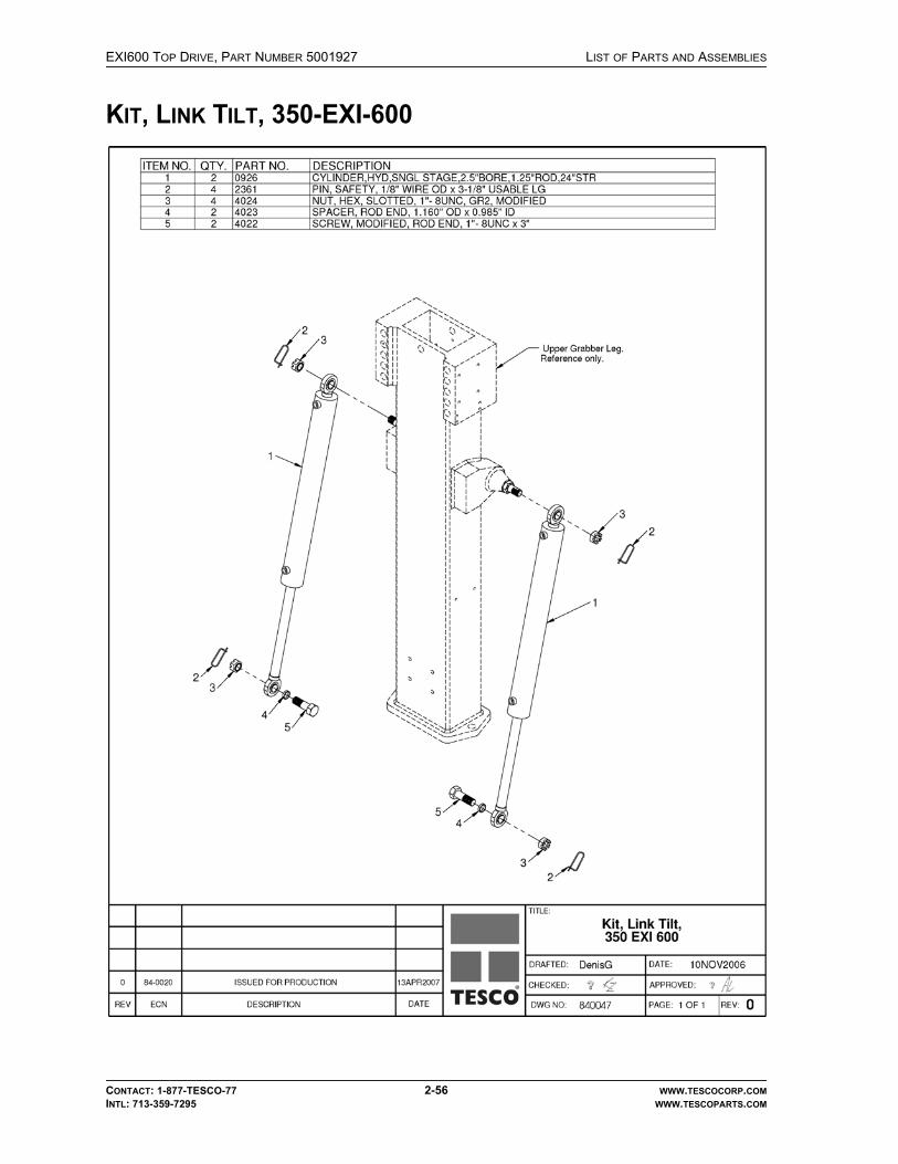
EXI600 TOP DRIVE, PART NUMBER 5001927 LIST OF PARTS AND ASSEMBLIES
CONTACT: 1-877-TESCO-77 2-56 WWW.TESCOCORP.COMINTL: 713-359-7295 WWW.TESCOPARTS.COM
KIT, LINK TILT, 350-EXI-600

LIST OF PARTS AND ASSEMBLIES EXI600 TOP DRIVE, PART NUMBER 5001927
CONTACT: 1-877-TESCO-77 2-57 WWW.TESCOCORP.COMINTL: 713-359-7295 WWW.TESCOPARTS.COM
This page has been left blank intentionally.

EXI600 TOP DRIVE, PART NUMBER 5001927 LIST OF PARTS AND ASSEMBLIES
CONTACT: 1-877-TESCO-77 2-58 WWW.TESCOCORP.COMINTL: 713-359-7295 WWW.TESCOPARTS.COM
KIT, MUDSAVER VALVE INSTALLATION, 350-EXI-600

LIST OF PARTS AND ASSEMBLIES EXI600 TOP DRIVE, PART NUMBER 5001927
CONTACT: 1-877-TESCO-77 2-59 WWW.TESCOCORP.COMINTL: 713-359-7295 WWW.TESCOPARTS.COM
This page has been left blank intentionally.

EXI600 TOP DRIVE, PART NUMBER 5001927 LIST OF PARTS AND ASSEMBLIES
CONTACT: 1-877-TESCO-77 2-60 WWW.TESCOCORP.COMINTL: 713-359-7295 WWW.TESCOPARTS.COM
CLAMP ASSEMBLY, CONNECTION LOCK, 7-7/8”

LIST OF PARTS AND ASSEMBLIES EXI600 TOP DRIVE, PART NUMBER 5001927
CONTACT: 1-877-TESCO-77 2-61 WWW.TESCOCORP.COMINTL: 713-359-7295 WWW.TESCOPARTS.COM
This page has been left blank intentionally.

EXI600 TOP DRIVE, PART NUMBER 5001927 LIST OF PARTS AND ASSEMBLIES
CONTACT: 1-877-TESCO-77 2-62 WWW.TESCOCORP.COMINTL: 713-359-7295 WWW.TESCOPARTS.COM
KIT, GRABBER LEG ASSEMBLY, 350-EXI-600
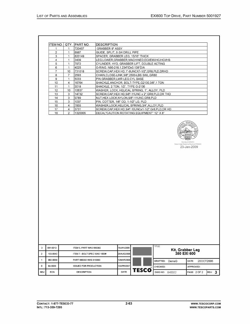
LIST OF PARTS AND ASSEMBLIES EXI600 TOP DRIVE, PART NUMBER 5001927
CONTACT: 1-877-TESCO-77 2-63 WWW.TESCOCORP.COMINTL: 713-359-7295 WWW.TESCOPARTS.COM

EXI600 TOP DRIVE, PART NUMBER 5001927 LIST OF PARTS AND ASSEMBLIES
CONTACT: 1-877-TESCO-77 2-64 WWW.TESCOCORP.COMINTL: 713-359-7295 WWW.TESCOPARTS.COM
GRABBER, 9”

LIST OF PARTS AND ASSEMBLIES EXI600 TOP DRIVE, PART NUMBER 5001927
CONTACT: 1-877-TESCO-77 2-65 WWW.TESCOCORP.COMINTL: 713-359-7295 WWW.TESCOPARTS.COM
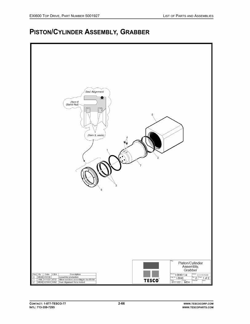
EXI600 TOP DRIVE, PART NUMBER 5001927 LIST OF PARTS AND ASSEMBLIES
CONTACT: 1-877-TESCO-77 2-66 WWW.TESCOCORP.COMINTL: 713-359-7295 WWW.TESCOPARTS.COM
PISTON/CYLINDER ASSEMBLY, GRABBER
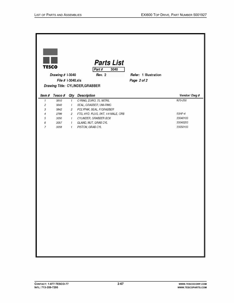
LIST OF PARTS AND ASSEMBLIES EXI600 TOP DRIVE, PART NUMBER 5001927
CONTACT: 1-877-TESCO-77 2-67 WWW.TESCOCORP.COMINTL: 713-359-7295 WWW.TESCOPARTS.COM

EXI600 TOP DRIVE, PART NUMBER 5001927 LIST OF PARTS AND ASSEMBLIES
CONTACT: 1-877-TESCO-77 2-68 WWW.TESCOCORP.COMINTL: 713-359-7295 WWW.TESCOPARTS.COM
KIT, TORQUE ARREST, 350-EXI-600, ENSIGN USA

LIST OF PARTS AND ASSEMBLIES EXI600 TOP DRIVE, PART NUMBER 5001927
CONTACT: 1-877-TESCO-77 2-69 WWW.TESCOCORP.COMINTL: 713-359-7295 WWW.TESCOPARTS.COM
This page has been left blank intentionally.
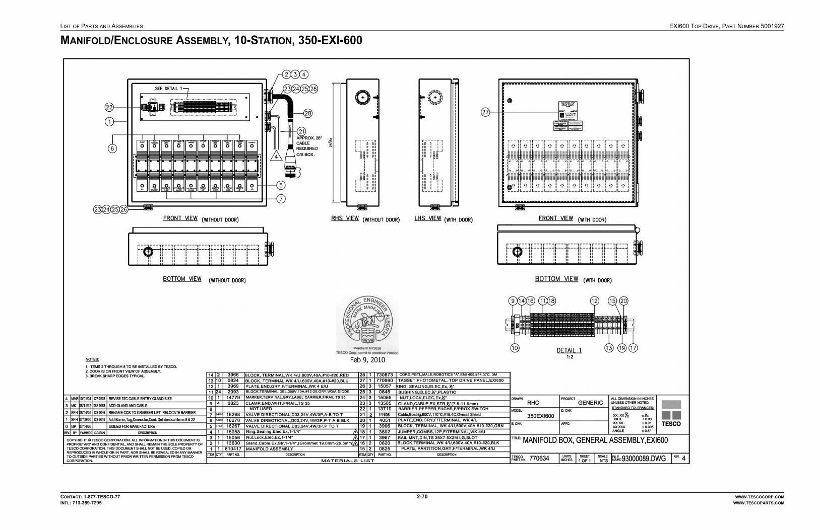
LIST OF PARTS AND ASSEMBLIES EXI600 TOP DRIVE, PART NUMBER 5001927
CONTACT: 1-877-TESCO-77 2-70 WWW.TESCOCORP.COMINTL: 713-359-7295 WWW.TESCOPARTS.COM
MANIFOLD/ENCLOSURE ASSEMBLY, 10-STATION, 350-EXI-600
EXI600 TOP DRIVE, PART NUMBER 5001927 LIST OF PARTS AND ASSEMBLIES
CONTACT: 1-877-TESCO-77 2-71 WWW.TESCOCORP.COMINTL: 713-359-7295 WWW.TESCOPARTS.COM
This page has been left blank intentionally.

LIST OF PARTS AND ASSEMBLIES EXI600 TOP DRIVE, PART NUMBER 5001927
CONTACT: 1-877-TESCO-77 2-72 WWW.TESCOCORP.COMINTL: 713-359-7295 WWW.TESCOPARTS.COM
ASSEMBLY, MOUNT, SERVICE LOOP, 350-EXI-600, ENSIGN USA

EXI600 TOP DRIVE, PART NUMBER 5001927 LIST OF PARTS AND ASSEMBLIES
CONTACT: 1-877-TESCO-77 2-73 WWW.TESCOCORP.COMINTL: 713-359-7295 WWW.TESCOPARTS.COM

EXI600 TOP DRIVE, PART NUMBER 5001927 LIST OF PARTS AND ASSEMBLIES
CONTACT: 1-877-TESCO-77 2-74 WWW.TESCOCORP.COMINTL: 713-359-7295 WWW.TESCOPARTS.COM
ASSEMBLY, TORQUE RESTRAINT, 350-EXI-600, ENSIGN USA

EXI600 TOP DRIVE, PART NUMBER 5001927 LIST OF PARTS AND ASSEMBLIES
CONTACT: 1-877-TESCO-77 2-75 WWW.TESCOCORP.COMINTL: 713-359-7295 WWW.TESCOPARTS.COM
This page has been left blank intentionally.
LIST OF PARTS AND ASSEMBLIES ENGINEERING SIGN-OFF
CONTACT: 1-877-TESCO-77 WWW.TESCOCORP.COM
INTL: 713-359-7295 WWW.TESCOPARTS.COM
ENGINEERING SIGN-OFF
This sign-off sheet indicates that this document has been approved for release by the Engineering Department at TESCO.
Document Completed By Signature Date Signed
Document Reviewed/Approved Date Signed
chane
Typewritten Text
Edward ChanAug. 13, 2010
chane
Typewritten Text
yef
Typewritten Text
August 13, 2010
yef
Typewritten Text
yef
Typewritten Text

ENGINEERING SIGN-OFF LIST OF PARTS AND ASSEMBLIES
CONTACT: 1-877-TESCO-77 WWW.TESCOCORP.COM
INTL: 713-359-7295 WWW.TESCOPARTS.COM
This page has been left blank intentionally.

alamk
Typewritten Text
June 18, 2010

alamk
Typewritten Text
June 18, 2010

alamk
Typewritten Text
June 18, 2010

alamk
Typewritten Text
June 18, 2010

alamk
Typewritten Text
June 18, 2010
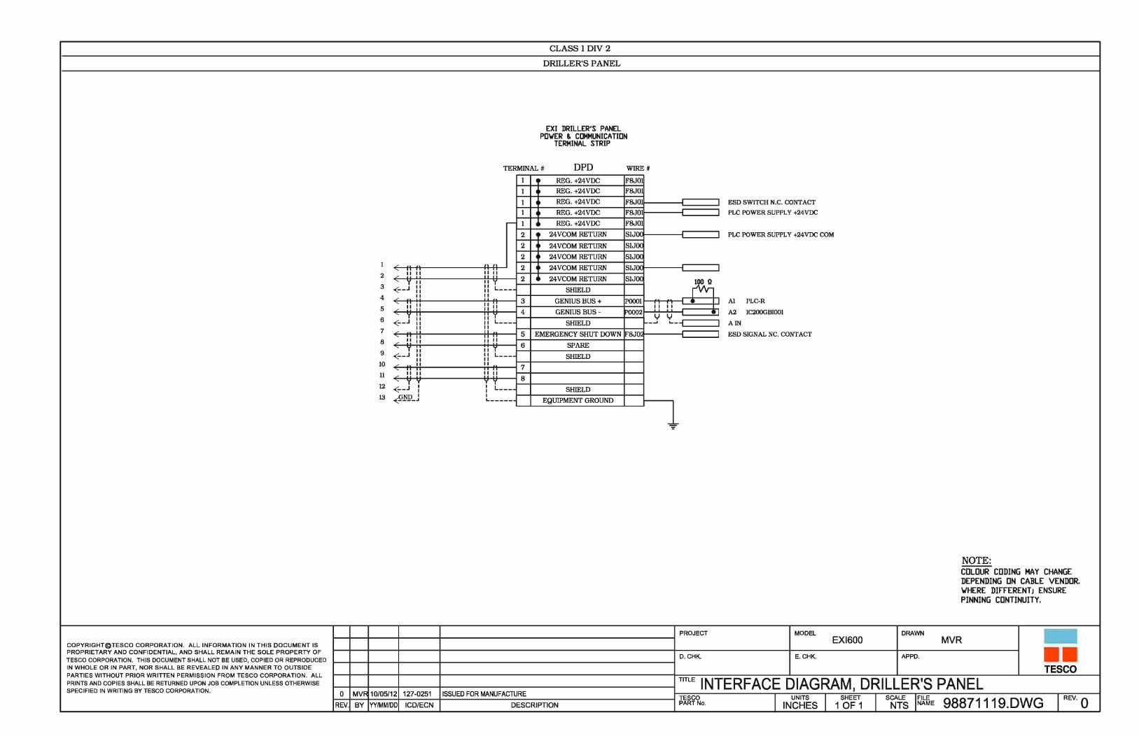
alamk
Typewritten Text
June 18. 2010

alamk
Typewritten Text
June 18, 2010

alamk
Typewritten Text
June 18, 2010

alamk
Typewritten Text
June 18, 2010

alamk
Typewritten Text
June 18, 2010

alamk
Typewritten Text
June 18, 2010

alamk
Typewritten Text
June 18, 2010

alamk
Typewritten Text
June 18, 2010

fallenm
Typewritten Text
27-Nov-2009

fallenm
Typewritten Text
27-Nov-2009

lerouh
Text Box
27 Oct 08

1 GQH 040623 6116 Add low temperature fluid specification
0 GHH 021217 Initial Release
Rev: By: Date: ICD: Description:
COPYRIGHT © TESCO CORPORATION. All information in this document is proprietary and confidential and shall remain the sole property of TESCO
Corporation. This document shall not be used, copied or reproduced in whole or in part, nor shall be revealed in any manner to outside parties without prior written
permission from TESCO Corporation. All prints and copies shall be returned upon job completion unless otherwise specified in writing by TESCO Corporation.
Page 1 of 1
Engineering Memorandum EM No: EM000041 Rev: 1 Date: June 17, 2004
Description: Specification – Hydraulic Fluid
Products Division 4930 – 74th Avenue SE
Calgary, Alberta T2C 3C9
Phone: (403) 301-4200
Fax: (403) 253-3578
Web: www.tescocorp.com
Originator: Gary Hansen
Date: September 27, 2002
Checked:
Date:
Approved:
Date:
Scope:
This EM specifies hydraulic fluid suitable for high and low ambient temperature applications (open and closed
loop hydraulic circuits). Hydraulic fluid listed in the left column is the first choice for all applications. Synthetic
automatic transmission fluid (ATF) listed in the right column is the alternative choice for electrical top drive
open loop application at very low ambient environment.
Specification:
Description Premium Anti-wear Hydraulic Fluid Synthetic Automatic Transmission
Fluid
ISO Grade 68 N/A
Viscosity Index 90 or higher per ASTM D-2270 182 or higher per ASTM D-2270
Ambient Temperature Range -20 oC to 50
oC -50
oC to -20
oC
Operating Temperature Range 0 oC to 85
oC -40
oC to 120
oC
Flash Point 160 oC or higher 222
oC or higher
Pour Point -30 oC or lower -56
oC or lower
Kinematic Viscosity 68 cST ± 5cST @ 40 oC
6.4 cST + 2cST @ 100 oC
36 cST ± 3cST @ 40 oC
7.5 cST ± 1cST @ 100 oC
Other Features � Oxidation and thermal stability
for long life
� Anti-wear properties and
extreme pressure characteristics
for protection against wear and
scouring
� Anti-foam, rust and
anticorrosion additives
� Elastomer compatibility for
extended seal and gasket life
� Oxidation and thermal stability
for long life
� Anti-wear protection
� Elastomer compatibility for
extended seal and gasket life
Approved Oils Mohawk HVI 68; Imperial Oil Univis
68; Shell Telus T68; PetroCanada
Harmony HVI 68
Amsoil Synthetic ATF
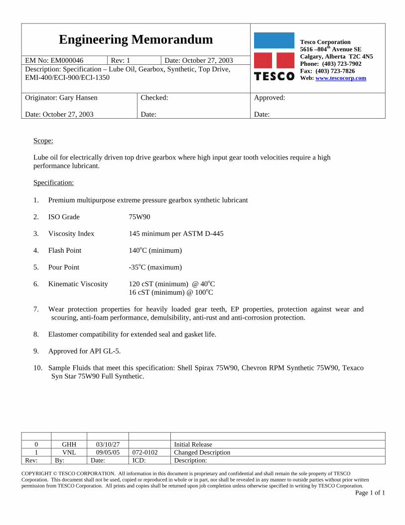
0 GHH 03/10/27 Initial Release 1 VNL 09/05/05 072-0102 Changed Description
Rev: By: Date: ICD: Description:
COPYRIGHT © TESCO CORPORATION. All information in this document is proprietary and confidential and shall remain the sole property of TESCO Corporation. This document shall not be used, copied or reproduced in whole or in part, nor shall be revealed in any manner to outside parties without prior written permission from TESCO Corporation. All prints and copies shall be returned upon job completion unless otherwise specified in writing by TESCO Corporation.
Page 1 of 1
Engineering Memorandum
Tesco Corporation 5616 –804th Avenue SE Calgary, Alberta T2C 4N5 Phone: (403) 723-7902 Fax: (403) 723-7826 Web: www.tescocorp.com
EM No: EM000046 Rev: 1 Date: October 27, 2003 Description: Specification – Lube Oil, Gearbox, Synthetic, Top Drive, EMI-400/ECI-900/ECI-1350
Originator: Gary Hansen Date: October 27, 2003
Checked: Date:
Approved: Date:
Scope: Lube oil for electrically driven top drive gearbox where high input gear tooth velocities require a high performance lubricant. Specification: 1. Premium multipurpose extreme pressure gearbox synthetic lubricant
2. ISO Grade 75W90 3. Viscosity Index 145 minimum per ASTM D-445
4. Flash Point 140oC (minimum) 5. Pour Point -35oC (maximum)
6. Kinematic Viscosity 120 cST (minimum) @ 40oC 16 cST (minimum) @ 100oC
7. Wear protection properties for heavily loaded gear teeth, EP properties, protection against wear and
scouring, anti-foam performance, demulsibility, anti-rust and anti-corrosion protection.
8. Elastomer compatibility for extended seal and gasket life.
9. Approved for API GL-5. 10. Sample Fluids that meet this specification: Shell Spirax 75W90, Chevron RPM Synthetic 75W90, Texaco
Syn Star 75W90 Full Synthetic.
erasmusp
Typewritten Text
15 May 2009

3 LW 06/04/24 LSW-136 Add EMI 400 and revise D4P hydraulic oil. 4 JYZ 07/04/19 111-0038 General Revision 5 VNL 09/05/05 072-0102 General Revision
Rev: By: Date: ICD/ECN: Description:
COPYRIGHT © TESCO CORPORATION. All information in this document is proprietary and confidential and shall remain the sole property of TESCO Corporation. This document shall not be used, copied or reproduced in whole or in part, nor shall be revealed in any manner to outside parties without prior written permission from TESCO Corporation. All prints and copies shall be returned upon job completion unless otherwise specified in writing by TESCO Corporation.
Page 1 of 7
Engineering Memorandum
Tesco Corporation 5616 –80th Avenue SE Calgary, Alberta T2C 4N5 Phone: (403) 723-7902 Fax: (403) 723-7826 Web: www.tescocorp.com
EM No: EM000113 Rev: 5 Date: Sep. 1, 2004 Description: Fluid Specification and Capacity Charts for Top Drive Systems
Originator: Louis Wen Date: Sep. 1, 2004
Checked: Date:
Approved: Date:
1. Introduction For maintenance and service purposes, occasionally it is required to empty and re-fill fluids such as Gearbox lubricant, Swivel lubricant, Pump drive lubricant, Hydraulic Oil, Engine lubricant, Engine coolant, and Motor/Drive coolant contained in Tesco top drive systems. This engineering memo serves to recommend a guideline for the type of fluids to use and amount required for re-fill.
2. Scope This memo covers guidelines types and amounts of fluids used in TESCO top drive systems. The fluids covered are Gearbox, Swivel, Pump Drive Gearbox, and Engine coolants, Hydraulic Oils, and Engine, Motor/Drive coolants.
For hydraulic top drives, the engine coolant capacity depends largely on the radiator ordered with the engine. The amount recommended was based on a specific previous order and thus subject to variation. But the value serves a good starting point.
For electrical top drives the Motor/Drive coolant capacity is based on DRS PA44 motor and MD-500 drive module setup.
3. Recommended Fluids and Capacities 3.1 HCI Top Drive System:
Component Description System Fluid Description Specification
Hydraulic System Hydraulic ISO 68 Hydraulic Oil EM000041
All Engine Cooling Systems Cooling Ethylene Glycol Base As per Engine OEM
All Engine Lubrication Systems Lube See below See below
Detroit Series 92 Crankcase Lube API CF-2 Oil, 2 Stroke Oil, 40 WT EM000040
Detroit Series 2000 Crankcase Lube API CG-4 Oil, 4 Stroke Oil EM000039
Caterpillar 3412 Crankcase Lube API CG-4 Oil, 4 Stroke Oil EM000039
Oilfield Swivel Lube SAE 75W-90 or SAE 80W-90 EM000042
Top Drive Gearbox Lube HD EP Automotive Hypoid Gear Oil EM000042
Pump Drive Gearbox Lube API CF-2 Oil, 2 Stroke Oil, 40WT EM000040
Table 1. Recommended HCI Fluids
erasmusp
Typewritten Text
15 May 2009
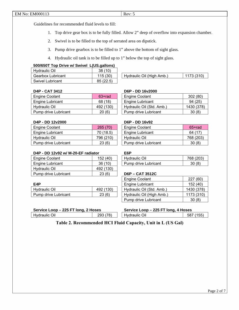
EM No: EM000113 Rev: 5
Page 2 of 7
Guidelines for recommended fluid levels to fill:
1. Top drive gear box is to be fully filled. Allow 2” deep of overflow into expansion chamber.
2. Swivel is to be filled to the top of serrated area on dipstick.
3. Pump drive gearbox is to be filled to 1” above the bottom of sight glass.
4. Hydraulic oil tank is to be filled up to 1” below the top of sight glass.
500/650T Top Drive w/ Swivel L(US.gallons) Hydraulic Oil 38 (10) Gearbox Lubricant 115 (30) Hydraulic Oil (High Amb.) 1173 (310) Swivel Lubricant 85 (22.5) D4P - CAT 3412 D6P - DD 16v2000 Engine Coolant 63+rad Engine Coolant 302 (80) Engine Lubricant 68 (18) Engine Lubricant 94 (25) Hydraulic Oil 492 (130) Hydraulic Oil (Std. Amb.) 1430 (378) Pump drive Lubricant 20 (6) Pump drive Lubricant 30 (8) D4P - DD 12v2000 D6P - DD 16v92 Engine Coolant 265 (70) Engine Coolant 65+rad Engine Lubricant 70 (18.5) Engine Lubricant 64 (17) Hydraulic Oil 796 (210) Hydraulic Oil 768 (203) Pump drive Lubricant 23 (6) Pump drive Lubricant 30 (8) D4P - DD 12v92 w/ M-20-EF radiator E6P Engine Coolant 152 (40) Hydraulic Oil 768 (203) Engine Lubricant 36 (10) Pump drive Lubricant 30 (8) Hydraulic Oil 492 (130) Pump drive Lubricant 23 (6) D6P – CAT 3512C Engine Coolant 227 (60) E4P Engine Lubricant 152 (40) Hydraulic Oil 492 (130) Hydraulic Oil (Std. Amb.) 1430 (378) Pump drive Lubricant 23 (6) Hydraulic Oil (High Amb.) 1173 (310) Pump drive Lubricant 30 (8) Service Loop – 225 FT long, 2 Hoses Service Loop – 225 FT long, 4 Hoses Hydraulic Oil 293 (78) Hydraulic Oil 587 (155)
Table 2. Recommended HCI Fluid Capacity, Unit in L (US Gal)

EM No: EM000113 Rev: 5
Page 3 of 7
3.2 HMI Top Drive System:
Component Description System Fluid Description Specification Hydraulic System Hydraulic ISO 68 Hydraulic Oil EM000041
All Engine Cooling Systems Cooling Ethylene Glycol Base As per Engine OEM
All Engine Lubrication Systems Lube API CG-4 Oil, 4 Stroke Oil EM000039
Oilfield Swivel Lube SAE 75W-90 or SAE 80W-90 EM000042
Top Drive Gearbox Lube HD EP Automotive Hypoid Gear Oil EM000042
Pump Drive Gearbox Lube API CF-2 Oil, 2 Stroke Oil, 40WT EM000040
Table 3. Recommended HMI Fluids
Guidelines for recommended fluid levels to fill:
1. Top drive gear box is to be fully filled. Allow 2” deep of overflow into expansion chamber.
2. Swivel is to be filled to the top of serrated area on dipstick.
3. Pump drive gearbox is to be filled when lubricant is 1” above the bottom of sight glass.
4. Hydraulic oil tank is to be filled up to 1” below the top of sight glass.
100/150/250T Top Drive w/ Swivel L(US.gallon)Hydraulic Oil 19 (5) Gearbox Lubricant 23 (6) 250T Tesco Swivel Lubricant 15 (4) 200/250T Rostel Swivel Lubricant 22 (6) 150T Swivel Lubricant 22 (6)
D2P - DD 60 w/ A660 radiator Engine Coolant 83 (22) Engine Lubricant 38 (10) Hydraulic Oil 596 (157.5) Pump drive Lubricant 23 (6)
D2P - CAT 3406 + Radiator S/N 30TB21852 Engine Coolant 100 (26.5) Engine Lubricant 38 (10) Hydraulic Oil 596 (157.5) Pump drive Lubricant 23 (6)
D2P - CAT C15 w/ Radiator S/N BEM01917 Engine Coolant 60 (16) Engine Lubricant 41.7 (11) Hydraulic Oil 596 (157.5) Pump drive Lubricant 23 (6)
E2P Hydraulic Oil 596 (157.5) Pump drive Lubricant 23 (6)
Service Loop – 225 FT long Hydraulic Oil 240 (63.5)
Table 4. Recommended HMI Fluid Capacity, Unit in L (US Gal)

EM No: EM000113 Rev: 5
Page 4 of 7
3.3 ECI Top Drive System:
Component Description System Fluid Description Specification
Hydraulic System Hydraulic ISO 68 Hydraulic Oil (Warm climate) EM000041
ATF Fully Synthetic Transmission Fluid (Cold climate) EM000041
Top Drive Motor Cooling Cooling Antifreeze, Ucartherm, 50/50 EM000048
Oilfield Swivel Lube SAE 75W-90 EM000046
Top Drive Gearbox Lube Oil, Gear, Synthetic SAE 75W-90, Tesco EM000046
Table 5. Recommended ECI Fluids
Guidelines for recommended fluid levels to fill:
1. Top drive gear box is to be filled up to the oil level line on the sight glass.
2. Swivel is to be filled to the top of serrated area on dipstick.
3. Hydraulic oil tank is to be filled up to 1” below the top of sight glass.
4. Motor/Drive coolant tank is to be filled up to 1” below the top of sight glass.
500/650T 900HP Top Drive w/Swivel L(US.gallons) 500/650T 1350HP Top Drive w/ Swivel Hydraulic Oil 31 (8) Hydraulic Oil 31 (8) Gearbox Lubricant 60 (16) Gearbox Lubricant 60 (16) Coolant 3 (0.8) Coolant 4 (1) Swivel Lubricant 80 (21) Swivel Lubricant 80 (21) Mechanical Module 900/1350HP Standard L(US.gallon) 900/1350HP High Ambient L(US.gallon)Hydraulic Oil 208 (55) Hydraulic Oil 208 (55) Coolant 810 (214) Coolant 810 (214) Power Module 900HP L(US.gallon) 1350HP L(US.gallon)Coolant 8 (2) Coolant 10 (2.5) Service Loop – 225 FT long 900HP L(US.gallon) 1350HP L(US.gallon)Hydraulic Oil 47 (12.5) Hydraulic Oil 47 (12.5) Coolant 56 (15) Coolant 91 (24)
Table 6. Recommended ECI Fluid Capacity, Unit in L (US Gal)

EM No: EM000113 Rev: 5
Page 5 of 7
3.4 EXI-600 Top Drive System:
Component Description System Fluid Description Specification
Hydraulic System Hydraulic ISO 68 Hydraulic Oil (Warm climate) EM000041
ATF Fully Synthetic Transmission Fluid (Cold climate) EM000041
Top Drive Gearbox Lube Oil, Gear, Semi-Synthetic SAE 80W-90, Tesco EM000042
Table 7. Recommended EXI-600 Fluids
Guidelines for recommended fluid levels to fill:
1. Top drive gear box is to be filled to ½” of the sight glass.
2. Hydraulic oil tank is to be filled up to 1” below the top of sight glass.
Top Drive L(US.gallon) Hydraulic Oil 20 (5) Gearbox Lubricant 22 (5.8) Hydraulic Power Unit L(US.gallon) Hydraulic Oil 172 (45) Service Loop – 225 ft long L(US.gallon) Hydraulic Oil 47 (12.5)
Table 8. Recommended EXI 600 Fluid Capacity, Unit in L (US Gal)

EM No: EM000113 Rev: 5
Page 6 of 7
3.5 EMI-400 Top Drive System:
Component Description System Fluid Description Specification Hydraulic System Hydraulic ISO 68 Hydraulic Oil (Warm climate) EM000041
ATF Fully Synthetic Transmission Fluid (Cold climate) EM000041
Top Drive Gearbox Lube Oil, Gear, Synthetic SAE 75W-90, Tesco EM000046
Table 9. Recommended EMI 400 Fluids
Guidelines for recommended fluid levels to fill:
1. Top drive gear box is to be filled to cover ¾ of the sight glass.
2. Hydraulic oil tank is to be filled up to 1” below the top of sight glass.
Top Drive L(US.gallon)Hydraulic Oil 20 (5) Gearbox Lubricant 19 (5)
Hydraulic Power Unit L(US.gallon)Hydraulic Oil 172 (45)
Service Loop – 225 FT long L(US.gallon)Hydraulic Oil 47 (12.5)
Table 10. Recommended EMI 400 Fluid Capacity, Unit in L (US Gal)
3.6 HXI Top Drive Systems:
Component Description System Fluid Description Specification
Hydraulic System Hydraulic Open Loop ISO 32 ISO32
Closed Loop ISO 68 ISO68
All Engine Cooling Systems Cooling Ethylene Glycol Base As per Engine OEM
All Engine Lubrication Systems Lube API CG-4-Oil,4 Stroke oil EM000039
Oilfield Swivel Lube SAE 75W-90 or SAE 80W-90 EM000042
Top Drive Gearbox Lube SAE 80W-90 EM000046
Pump Drive Gearbox Lube SAE 80W-90 EM000046
Table 11. Recommended HXI and D4P-700,C-18 Fluids
Guidelines for recommended fluid levels to fill:
1. Standard Gearbox Lubricant is specified in EM000046. Depending on customer requirements, it can be upgraded to ISO 220 Grade.
2. Pump Drive Gearbox to be filled when lubricant is 1” above the bottom of sight glass.
3. Hydraulic oil tank is to be filled up to 1” below the top of sight glass.
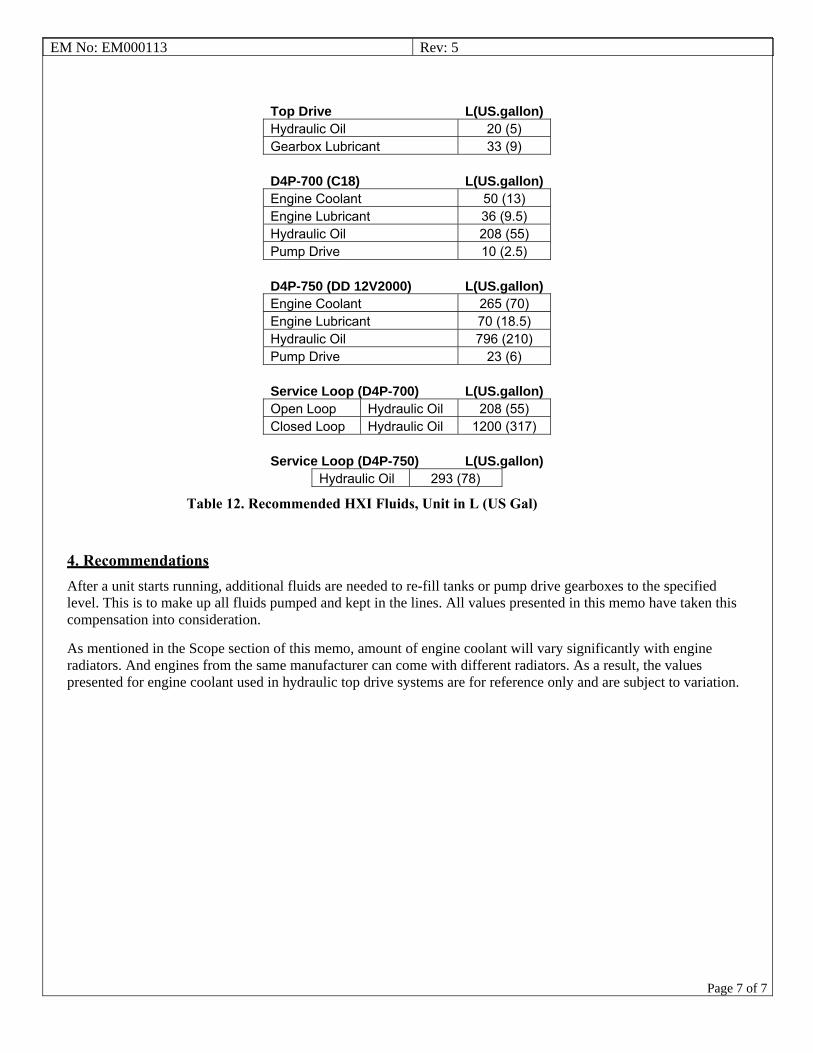
EM No: EM000113 Rev: 5
Page 7 of 7
Top Drive L(US.gallon)Hydraulic Oil 20 (5) Gearbox Lubricant 33 (9)
D4P-700 (C18) L(US.gallon)Engine Coolant 50 (13) Engine Lubricant 36 (9.5) Hydraulic Oil 208 (55) Pump Drive 10 (2.5)
D4P-750 (DD 12V2000) L(US.gallon)Engine Coolant 265 (70) Engine Lubricant 70 (18.5) Hydraulic Oil 796 (210) Pump Drive 23 (6)
Service Loop (D4P-700) L(US.gallon)Open Loop Hydraulic Oil 208 (55) Closed Loop Hydraulic Oil 1200 (317)
Service Loop (D4P-750) L(US.gallon)Hydraulic Oil 293 (78)
Table 12. Recommended HXI Fluids, Unit in L (US Gal)
4. Recommendations After a unit starts running, additional fluids are needed to re-fill tanks or pump drive gearboxes to the specified level. This is to make up all fluids pumped and kept in the lines. All values presented in this memo have taken this compensation into consideration.
As mentioned in the Scope section of this memo, amount of engine coolant will vary significantly with engine radiators. And engines from the same manufacturer can come with different radiators. As a result, the values presented for engine coolant used in hydraulic top drive systems are for reference only and are subject to variation.

System Description
EXI Top Drive System
350/400TON EXI 600HP
DOCUMENT NAME: 880076 REV 2


COPYRIGHT AND DISCLAIMER SYSTEM DESCRIPTION
Tesco Corporation ("TESCO") has made every effort to ensure that this document contains accurate and current information for the TESCO top drive, however, the document is intended to be used in conjunction with a complete training program and on-site supervision and TESCO does not warrant or guarantee that the information contained herein is either complete or accurate in every respect, and the reader hereby protects, indemnifies and holds harmless Tesco Corporation together with its directors, officers, employees and agents from and against all liability for personal injury, death or property damage to any person arising directly or indirectly from the use by the reader of the information contained in the document.
This equipment was filled at the factory with TESCO ULTREX™ brand fluids and greases. To ensure maximum performance and to avoid cross-contamination, we strongly recommend the continued usage of TESCO ULTREX™ lubricants, unless otherwise specified.
TESCO ULTREX™ is a trademark and TESCO® is a registered trademark of Tesco Corporation.
Tesco Corporation © 2009
Contact Information
Corporate Head Office3993 W. Sam Houston Parkway No., Suite 100
Houston, Texas, 77043USA
www.tescocorp.comwww.tescoparts.com
Telephone: (713) 359-7000Fax: (713) 359-7001
After Market Sales and Service ContactToll Free North America: 1-877-TESCO-77
International: 713-359-7295
CONTACT: 1-877-TESCO-77 350/400 TON EXI 600HP WWW.TESCOCORP.COM
INTL: 713-359-7295 I WWW.TESCOPARTS.COM

REVISION INFORMATION SYSTEM DESCRIPTION
Revision Information
Version Date Description of Changes
0 August 2007 First release of document
1 October 2008 Upgrade 350 EXI 600 to 350/400 EXI 600
2 September 2009 Added TESCO ULTREX™ recommendations and updated the footer to contain contact information.
CONTACT: 1-877-TESCO-77 350/400 TON EXI 600HP WWW.TESCOCORP.COM
INTL: 713-359-7295 II WWW.TESCOPARTS.COM

TABLE OF CONTENTS SYSTEM DESCRIPTION
TABLE OF CONTENTS
SAFETY INSTRUCTIONS . . . . . . . . . . . . . . . . . . . . . . . . . . . . . . . . . . . . . . . . . . . . . . . . . V
CHAPTER 1: ABOUT THIS DOCUMENT . . . . . . . . . . . . . . . . . . . . . . . . . . . . . . . . . . . . . . 1
CHAPTER 2: TOP DRIVE SYSTEM DESCRIPTION . . . . . . . . . . . . . . . . . . . . . . . . . . . . . . . 3
Introduction and General Specifications . . . . . . . . . . . . . . . . . . . . . . . . . . . . . . . . . . . . . . . . . . . . . . 3
Top Drive Components. . . . . . . . . . . . . . . . . . . . . . . . . . . . . . . . . . . . . . . . . . . . . . . . . . . . . . . . . . . . . 6
Gearbox . . . . . . . . . . . . . . . . . . . . . . . . . . . . . . . . . . . . . . . . . . . . . . . . . . . . . . . . . . . . . . . . . . . . . . 8
Load Collar and Load Nut. . . . . . . . . . . . . . . . . . . . . . . . . . . . . . . . . . . . . . . . . . . . . . . . . . . . . . . . . 8
Mudsaver Valve . . . . . . . . . . . . . . . . . . . . . . . . . . . . . . . . . . . . . . . . . . . . . . . . . . . . . . . . . . . . . . . . 8
Pipe Handler. . . . . . . . . . . . . . . . . . . . . . . . . . . . . . . . . . . . . . . . . . . . . . . . . . . . . . . . . . . . . . . . . . . 8
Counter-Balance. . . . . . . . . . . . . . . . . . . . . . . . . . . . . . . . . . . . . . . . . . . . . . . . . . . . . . . . . . . . . . . . 8
Top Drive Power Supply. . . . . . . . . . . . . . . . . . . . . . . . . . . . . . . . . . . . . . . . . . . . . . . . . . . . . . . . . . 9
Travel Stand . . . . . . . . . . . . . . . . . . . . . . . . . . . . . . . . . . . . . . . . . . . . . . . . . . . . . . . . . . . . . . . . . . . 9
Power Module . . . . . . . . . . . . . . . . . . . . . . . . . . . . . . . . . . . . . . . . . . . . . . . . . . . . . . . . . . . . . . . . . . . . 9
Main Panel . . . . . . . . . . . . . . . . . . . . . . . . . . . . . . . . . . . . . . . . . . . . . . . . . . . . . . . . . . . . . . . . . . . . 9
600V Distribution Panel . . . . . . . . . . . . . . . . . . . . . . . . . . . . . . . . . . . . . . . . . . . . . . . . . . . . . . . . . . 9
15KVA 600: 208/120V transformer. . . . . . . . . . . . . . . . . . . . . . . . . . . . . . . . . . . . . . . . . . . . . . . . . . 9
120/208V Distribution Panel . . . . . . . . . . . . . . . . . . . . . . . . . . . . . . . . . . . . . . . . . . . . . . . . . . . . . . . 9
Drive and Building Cooling . . . . . . . . . . . . . . . . . . . . . . . . . . . . . . . . . . . . . . . . . . . . . . . . . . . . . . . . 9
Auxiliary Hydraulic Power Unit . . . . . . . . . . . . . . . . . . . . . . . . . . . . . . . . . . . . . . . . . . . . . . . . . . . . . 10
Torque Arrest System. . . . . . . . . . . . . . . . . . . . . . . . . . . . . . . . . . . . . . . . . . . . . . . . . . . . . . . . . . . . . 11
Torque Bushing . . . . . . . . . . . . . . . . . . . . . . . . . . . . . . . . . . . . . . . . . . . . . . . . . . . . . . . . . . . . . . . 11
Extend Frame and Extend Arms . . . . . . . . . . . . . . . . . . . . . . . . . . . . . . . . . . . . . . . . . . . . . . . . . . 11
Torque Track . . . . . . . . . . . . . . . . . . . . . . . . . . . . . . . . . . . . . . . . . . . . . . . . . . . . . . . . . . . . . . . . . 11
Torque Beam and T-bar . . . . . . . . . . . . . . . . . . . . . . . . . . . . . . . . . . . . . . . . . . . . . . . . . . . . . . . . . 11
Service Loop . . . . . . . . . . . . . . . . . . . . . . . . . . . . . . . . . . . . . . . . . . . . . . . . . . . . . . . . . . . . . . . . . . . . 13
Electrical Cables. . . . . . . . . . . . . . . . . . . . . . . . . . . . . . . . . . . . . . . . . . . . . . . . . . . . . . . . . . . . . . . 14
Hydraulic Hoses . . . . . . . . . . . . . . . . . . . . . . . . . . . . . . . . . . . . . . . . . . . . . . . . . . . . . . . . . . . . . . . 14
Driller’s Panel . . . . . . . . . . . . . . . . . . . . . . . . . . . . . . . . . . . . . . . . . . . . . . . . . . . . . . . . . . . . . . . . . . . 14
Safety Interlocks . . . . . . . . . . . . . . . . . . . . . . . . . . . . . . . . . . . . . . . . . . . . . . . . . . . . . . . . . . . . . . . . . 15
Emergency Shut Down (E.S.D.) . . . . . . . . . . . . . . . . . . . . . . . . . . . . . . . . . . . . . . . . . . . . . . . . . . . 15
Air interlocks . . . . . . . . . . . . . . . . . . . . . . . . . . . . . . . . . . . . . . . . . . . . . . . . . . . . . . . . . . . . . . . . . . 15
Shipping Containers . . . . . . . . . . . . . . . . . . . . . . . . . . . . . . . . . . . . . . . . . . . . . . . . . . . . . . . . . . . . . . 17
Container 1 . . . . . . . . . . . . . . . . . . . . . . . . . . . . . . . . . . . . . . . . . . . . . . . . . . . . . . . . . . . . . . . . . . . 17
Container 2 . . . . . . . . . . . . . . . . . . . . . . . . . . . . . . . . . . . . . . . . . . . . . . . . . . . . . . . . . . . . . . . . . . . 17
Container 3 . . . . . . . . . . . . . . . . . . . . . . . . . . . . . . . . . . . . . . . . . . . . . . . . . . . . . . . . . . . . . . . . . . . 17
CONTACT: 1-877-TESCO-77 350/400 TON EXI 600HP WWW.TESCOCORP.COM
INTL: 713-359-7295 III WWW.TESCOPARTS.COM

SYSTEM DESCRIPTION TABLE OF CONTENTS
Options . . . . . . . . . . . . . . . . . . . . . . . . . . . . . . . . . . . . . . . . . . . . . . . . . . . . . . . . . . . . . . . . . . . . . . . . .18
Elevators and Elevator Links. . . . . . . . . . . . . . . . . . . . . . . . . . . . . . . . . . . . . . . . . . . . . . . . . . . . . .18
Additional Safety Valve and Actuator . . . . . . . . . . . . . . . . . . . . . . . . . . . . . . . . . . . . . . . . . . . . . . .18
Subs . . . . . . . . . . . . . . . . . . . . . . . . . . . . . . . . . . . . . . . . . . . . . . . . . . . . . . . . . . . . . . . . . . . . . . . .18
Grabber Drill Pipe Guides . . . . . . . . . . . . . . . . . . . . . . . . . . . . . . . . . . . . . . . . . . . . . . . . . . . . . . . .18
Rotary Table Stabilizer Bushings . . . . . . . . . . . . . . . . . . . . . . . . . . . . . . . . . . . . . . . . . . . . . . . . . .18
Rotary Hose and Standpipe Extension . . . . . . . . . . . . . . . . . . . . . . . . . . . . . . . . . . . . . . . . . . . . . .18
Torque Arrest System . . . . . . . . . . . . . . . . . . . . . . . . . . . . . . . . . . . . . . . . . . . . . . . . . . . . . . . . . . .18
Alarms . . . . . . . . . . . . . . . . . . . . . . . . . . . . . . . . . . . . . . . . . . . . . . . . . . . . . . . . . . . . . . . . . . . . . . .18
Driller’s Panel . . . . . . . . . . . . . . . . . . . . . . . . . . . . . . . . . . . . . . . . . . . . . . . . . . . . . . . . . . . . . . . . .19
Power Supply Options. . . . . . . . . . . . . . . . . . . . . . . . . . . . . . . . . . . . . . . . . . . . . . . . . . . . . . . . . . .19
Other Available Options . . . . . . . . . . . . . . . . . . . . . . . . . . . . . . . . . . . . . . . . . . . . . . . . . . . . . . . . .19
CONTACT: 1-877-TESCO-77 350/400 TON EXI 600HP WWW.TESCOCORP.COM
INTL: 713-359-7295 IV WWW.TESCOPARTS.COM

SAFETY INSTRUCTIONS SYSTEM DESCRIPTION
SAFETY INSTRUCTIONS
Warning! Before operating and servicing this top drive system, always read and follow all safety instructions such as the warnings and cautions mentioned below and throughout the manual.
Top Drive System users risk injury to themselves and to others if the top drive is used improperly and/or safety precautions are not followed. TESCO advises personnel who work with or near the equipment to always wear proper personal protective equipment (PPE). Proper PPE consists of, but is not limited to, the following:
• hearing protection (ear defenders)• hard hat• safety glasses• steel toe shoes• fall protection when working above 6.5 ft (2 m), or the minimum height
requirement as directed by local jurisdiction.
Caution: This equipment is designed and certified for use in a hazardous environment. When maintenance requires replacement of parts, only identical parts can be used. Using alternate, non-iden-tical parts as a substitution may void compliance and certification.
Caution: Always perform the correct lock-out procedures as recommended by the Safety or Loss Prevention department before implementing maintenance.
Caution: Only authorized personnel can operate the top drive system.
Caution: This equipment can generate noise up to 90 decibels. Hearing protection suitable for this noise level must be worn when operating this equipment.
!
!
!
!
!
CONTACT: 1-877-TESCO-77 350/400 TON EXI 600HP WWW.TESCOCORP.COM
INTL: 713-359-7295 V WWW.TESCOPARTS.COM

SYSTEM DESCRIPTION SAFETY INSTRUCTIONS
Warning! Electrical voltages of different potentials are used throughout the TESCO top drive components (600 VAC, 208 VAC, 120 VAC, 840 VDC, 5-24 VDC). It is imperative that only qualified personnel install, maintain and/or troubleshoot the electrical systems. A severe hazard exists to personnel not accustomed to, or familiar with, electrical hazards and procedures.
Warning! There are high voltage capacitors installed in the ACS800 drive module. It is imperative that at least 5 minutes elapse, after power to the drive has been turned off, before any testing or repairs be undertaken at the module. The capacitors require time to ‘drain’ their stored electrical energy.
Warning! Accumulators used in the auxiliary hydraulic system are under the pressure of gas. Release this pressure before any maintenance is done on the auxiliary hydraulic system.
!
!
!
CONTACT: 1-877-TESCO-77 350/400 TON EXI 600HP WWW.TESCOCORP.COM
INTL: 713-359-7295 VI WWW.TESCOPARTS.COM

CHAPTER 1: ABOUT THIS DOCUMENT SYSTEM DESCRIPTION
CHAPTER 1: ABOUT THIS DOCUMENT
This document contains a description of the major components of the Electric Integrated Top Drive System with integrated quill.
A complete EXI Top Drive System consists of the following:
• top drive• power module (drive building)• auxiliary hydraulic power unit • interconnecting service loop and reel• torque arrest system• associated buildings, containers, and equipment
This document provides a brief description of each major component, as well as a list of available spares and options.
Important Note: Illustrations contained herein are provided for reference purposes only, equipment shown may differ from the actual unit appearance.
Table 1-1: Where to find more information
For information on Refer to
• installation• rig up• commissioning• pre-operational checklists• rig out procedures
Installation Guide
• setting torque and speed• driller's panel functions and operating descriptions• making connections• drilling ahead• tripping• freeing stuck pipe
Operations Guide
• load path inspections• maintenance/service schedules• component disassembly and reassembly
Maintenance Guide
TESCO manufactured parts and part numbers Parts List
troubleshooting Troubleshooting Guide (where available)
• electrical schematics• hydraulic schematics• gearbox lubrication schematics
System schematics
available options and spares TESCO representative
CONTACT: 1-877-TESCO-77 350/400 TON EXI 600HP WWW.TESCOCORP.COM
INTL: 713-359-7295 1 WWW.TESCOPARTS.COM

SYSTEM DESCRIPTION CHAPTER 1: ABOUT THIS DOCUMENT
This page has been left blank intentionally.
CONTACT: 1-877-TESCO-77 350/400 TON EXI 600HP WWW.TESCOCORP.COM
INTL: 713-359-7295 2 WWW.TESCOPARTS.COM

CHAPTER 2: TOP DRIVE SYSTEM DESCRIPTION SYSTEM DESCRIPTION
CHAPTER 2: TOP DRIVE SYSTEM DESCRIPTION
INTRODUCTION AND GENERAL SPECIFICATIONS
The TESCO EXI Top Drive System is a compact, full featured top drive, designed for use on land-based drilling rigs with narrow masts.
The EXI Top Drive System features an AC induction motor and variable frequency drive system. The EXI Top Drive System can be operated from a self-contained generator, or connected directly to the rig’s AC Bus (600 VAC - 50 or 60 cycle).
Figure 2-1: 350 EXI 600 Top Drive, shown w/ pipe guard, counterbalance system and travel stand
CONTACT: 1-877-TESCO-77 350/400TON EXI 600HP WWW.TESCOCORP.COM
INTL: 713-359-7295 3 WWW.TESCOPARTS.COM

SYSTEM DESCRIPTION CHAPTER 2: TOP DRIVE SYSTEM DESCRIPTION
Metric unit conversions (in brackets) have been provided for convenience only. All product specifications use the original imperial units unless indicated otherwise.
All weight values are approximate.
Figure 2-2: 400 EXI 600 Top Drive, shown w/ pipe guard, counterbalance system and travel stand
Table 2-1: EXI Top Drive System specifications
Imperial Metric
Rated capacity through load collar 350/400 Ton 318/363 tonne
Rated horsepower 600 hp 448 kW
Max. continous drill torque 30,000 ft-lb 4 067 daN-m
Make-up/Breakout torque 45,000 ft-lb 6 101 daN-m
Max. speed 220 RPM
Weight of the top drive plus:• elevators• elevator links• counterbalance system
25,000 lb 11 340 kg
Length (250T, with 9 ft links) 237 in. 6.02 m
Width 48 in. 1.23 m
Quill connection NC61 SRG
Hazardous area certification CSA Class 1 Div II or II 2 G
CONTACT: 1-877-TESCO-77 350/400TON EXI 600HP WWW.TESCOCORP.COM
INTL: 713-359-7295 4 WWW.TESCOPARTS.COM

CHAPTER 2: TOP DRIVE SYSTEM DESCRIPTION SYSTEM DESCRIPTION
Table 2-2: Torque Arrest System specifications
Imperial Metric
Weight of the following:• torque track (92 ft long)• anchor beam• torque bushing• extend frame• clamps
8,400 lb 3,833 kg
Standard track length 92 ft - 146 ft 28.4 - 44.5 m
Hazardous area certification II 2 G
Table 2-3: Power Module specifications
Imperial Metric
Weight of the following:• drive components• distribution panels• HVAC unit• transformer
11,500 lb 5 216 kg
Dimensions 149(L) x 90(W) x 89(H) in. 3.78(L) x 2.29(W) x 2.26(H) m
Hazaradous area certificationCSA - general purpose or safe area
Table 2-4: Auxiliary Hydraulic Power Unit specifications
Imperial Metric
Total weight, dry 700 lb (318 kg)
Dimensions 44(L) x 25(W) x 75(H) in. 1.1(L) x 0.64(W) x 1.9(H) m
Delivery capacity 7 gpm 26.5 l/min
Delivery pressure 2,500 psi 172.4 bar
Motor voltage 575V 60 Hz
Hazardous area certificationCSA general purpose or safe area
Table 2-5: Service Loop specifications
Imperial Metric
Weight of the following:• reels• cables• hoses
3,800 lb 1 724 kg
Hazardous area certification CSA Class 1 Div II or II 2 G
Table 2-6: Driller’s Panel specifications
Imperial Metric
Weight 80 lb 36.3 kg
Dimensions 35(L) x 16(W) x 7(H) in. 0.9(L) x 0.4(W) x 0.2(H) m
Hazardous area certification CSA class 1 Div II or II 3 G
CONTACT: 1-877-TESCO-77 350/400TON EXI 600HP WWW.TESCOCORP.COM
INTL: 713-359-7295 5 WWW.TESCOPARTS.COM

SYSTEM DESCRIPTION CHAPTER 2: TOP DRIVE SYSTEM DESCRIPTION
TOP DRIVE COMPONENTS
Figure 2-3: 350 EXI 600 Top Drive System General Assembly
CONTACT: 1-877-TESCO-77 350/400TON EXI 600HP WWW.TESCOCORP.COM
INTL: 713-359-7295 6 WWW.TESCOPARTS.COM
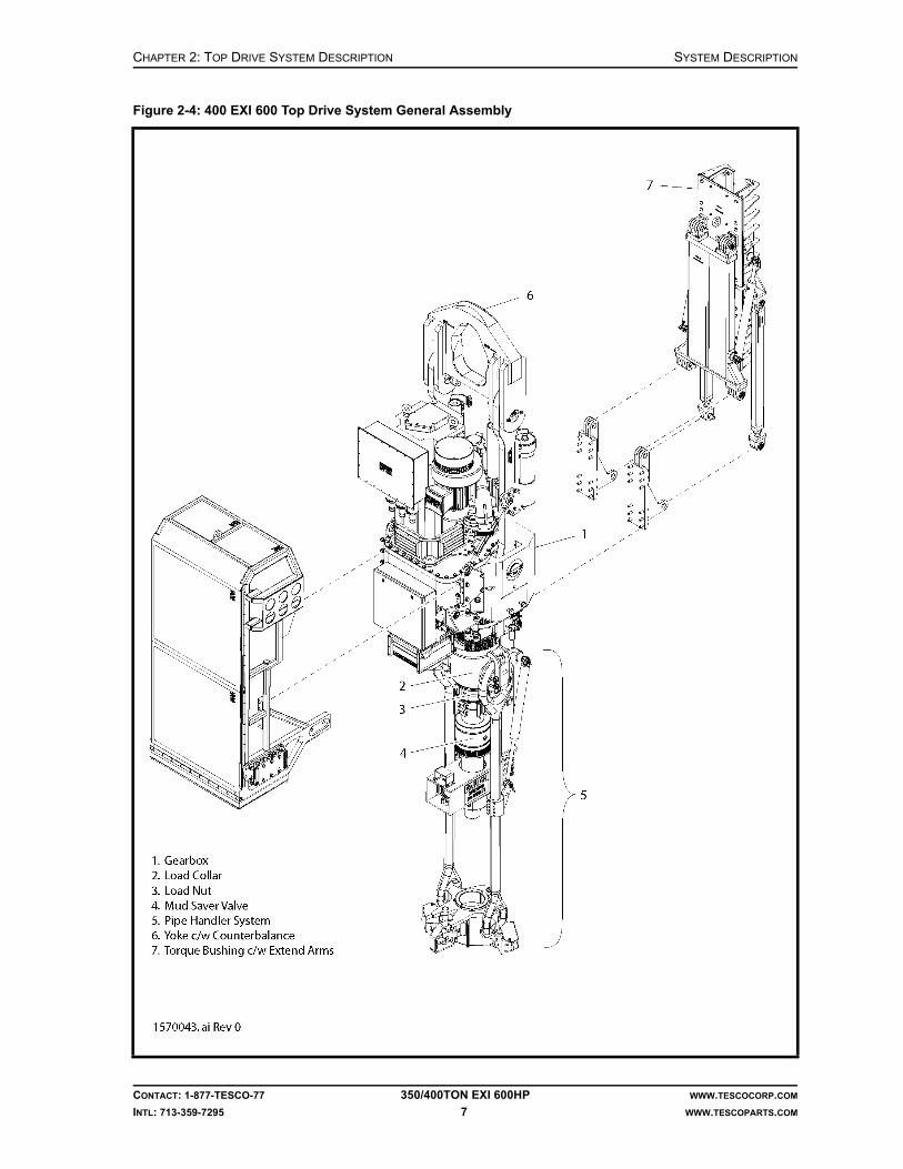
CHAPTER 2: TOP DRIVE SYSTEM DESCRIPTION SYSTEM DESCRIPTION
Figure 2-4: 400 EXI 600 Top Drive System General Assembly
CONTACT: 1-877-TESCO-77 350/400TON EXI 600HP WWW.TESCOCORP.COM
INTL: 713-359-7295 7 WWW.TESCOPARTS.COM
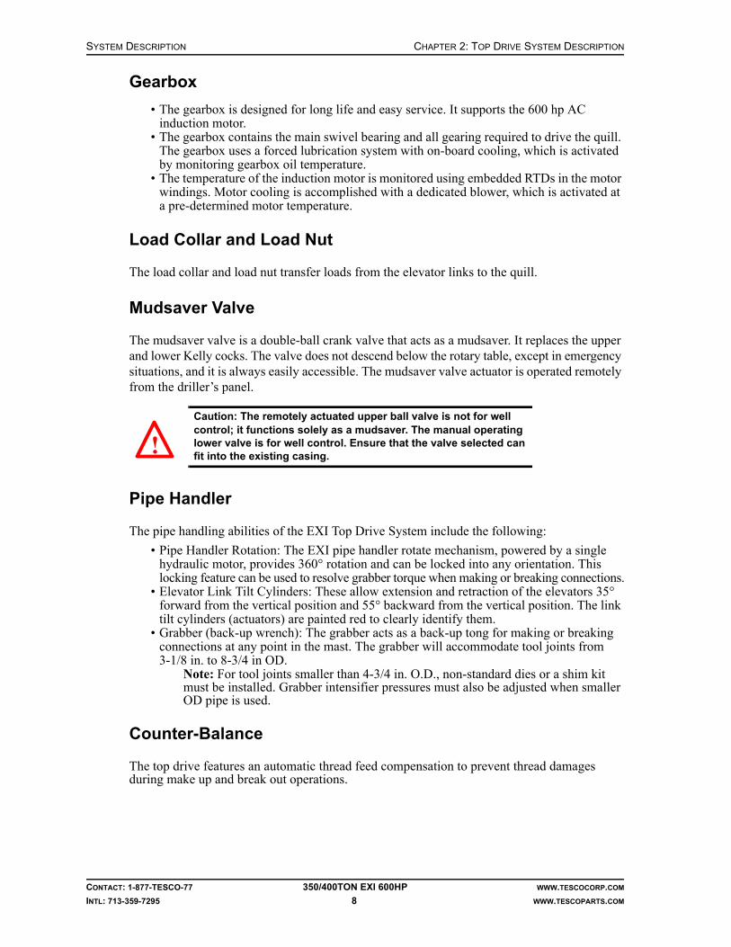
SYSTEM DESCRIPTION CHAPTER 2: TOP DRIVE SYSTEM DESCRIPTION
Gearbox
• The gearbox is designed for long life and easy service. It supports the 600 hp AC induction motor.
• The gearbox contains the main swivel bearing and all gearing required to drive the quill. The gearbox uses a forced lubrication system with on-board cooling, which is activated by monitoring gearbox oil temperature.
• The temperature of the induction motor is monitored using embedded RTDs in the motor windings. Motor cooling is accomplished with a dedicated blower, which is activated at a pre-determined motor temperature.
Load Collar and Load Nut
The load collar and load nut transfer loads from the elevator links to the quill.
Mudsaver Valve
The mudsaver valve is a double-ball crank valve that acts as a mudsaver. It replaces the upper and lower Kelly cocks. The valve does not descend below the rotary table, except in emergency situations, and it is always easily accessible. The mudsaver valve actuator is operated remotely from the driller’s panel.
Caution: The remotely actuated upper ball valve is not for well control; it functions solely as a mudsaver. The manual operating lower valve is for well control. Ensure that the valve selected can fit into the existing casing.
Pipe Handler
The pipe handling abilities of the EXI Top Drive System include the following:
• Pipe Handler Rotation: The EXI pipe handler rotate mechanism, powered by a single hydraulic motor, provides 360° rotation and can be locked into any orientation. This locking feature can be used to resolve grabber torque when making or breaking connections.
• Elevator Link Tilt Cylinders: These allow extension and retraction of the elevators 35° forward from the vertical position and 55° backward from the vertical position. The link tilt cylinders (actuators) are painted red to clearly identify them.
• Grabber (back-up wrench): The grabber acts as a back-up tong for making or breaking connections at any point in the mast. The grabber will accommodate tool joints from 3-1/8 in. to 8-3/4 in OD.
Note: For tool joints smaller than 4-3/4 in. O.D., non-standard dies or a shim kit must be installed. Grabber intensifier pressures must also be adjusted when smaller OD pipe is used.
Counter-Balance
The top drive features an automatic thread feed compensation to prevent thread damages during make up and break out operations.
!
CONTACT: 1-877-TESCO-77 350/400TON EXI 600HP WWW.TESCOCORP.COM
INTL: 713-359-7295 8 WWW.TESCOPARTS.COM

CHAPTER 2: TOP DRIVE SYSTEM DESCRIPTION SYSTEM DESCRIPTION
Top Drive Power Supply
The top drive motor is powered by a variable frequency drive system, which is located in the power module. All top drive robotic functions are fluid powered by an auxiliary hydraulic system electrically controlled using 24 VDC via the PLC control.
Travel Stand
The top drive is shipped in its own travel stand (handling frame). This frame allows the top drive to be transported and handled using standard rig moving equipment.
POWER MODULE
All electrical distribution and control components are contained within a single walk-in enclosure referred to as the power module.
ACS800 Electric Drive System
The ACS800 electric drive is a modular unit comprised of four main sections: a main breaker and control cabinet, a diode supply unit, two inverter modules, and a dynamic braking unit. The main breaker is rated for 1000A and features an undervoltage trip circuit, which is tied directly to the ESD control on the driller’s panel. The dynamic brake is connected to a grid resistor, which is mounted on the rear outside wall of the power module.
Main Panel
This panel provides the interface between the main PLC, the Driller’s Panel, and sensor information from the Top Drive Panel. The main PLC also communicates with the drive via serial link RS485. Information and commands are processed and distributed to the relevant components.
600V Distribution Panel
This panel contains main breakers for 120/208V power distribution and hydraulic tank heater. It also houses motor starters for the motor and drive blower and for the auxiliary hydraulic pump.
15KVA 600: 208/120V transformer
The transformer is for 208/120V power distribution.
120/208V Distribution Panel
This panel houses breakers for AC/DC control power supply, motor heater, building lighting, and air conditioning.
Drive and Building Cooling
Drive system is air-cooled by a separate blower motor. The temperature of the whole building can be regulated by a 5 ton HVAC (heating, ventilation, and air conditioning) system, which regulates the temperature inside the power module via a programmable thermostat.
CONTACT: 1-877-TESCO-77 350/400TON EXI 600HP WWW.TESCOCORP.COM
INTL: 713-359-7295 9 WWW.TESCOPARTS.COM

SYSTEM DESCRIPTION CHAPTER 2: TOP DRIVE SYSTEM DESCRIPTION
AUXILIARY HYDRAULIC POWER UNIT
The hydraulic power unit consists of:
• an oil reservoir (40 gallons; 151.4 liters),• a gear pump (7 gpm; 26.5 liters/minute), which is coupled to a• 10 hp (7.46 kW) electric motor, and• all necessary piping and control features.
Basic control circuitry for the hydraulic system is mounted on the top drive. The auxiliary system operates at 2,300 psi (15 858 kPa) at the pump level.
Figure 2-5: Auxiliary Hydraulic Power Unit
CONTACT: 1-877-TESCO-77 350/400TON EXI 600HP WWW.TESCOCORP.COM
INTL: 713-359-7295 10 WWW.TESCOPARTS.COM

CHAPTER 2: TOP DRIVE SYSTEM DESCRIPTION SYSTEM DESCRIPTION
TORQUE ARREST SYSTEM
The torque arrest system consists of the following components:
• torque bushing• extend frame• extend arms• extend hydraulic cylinders• torque track• T-bar• torque beam, torque beam clamps, stabilization devices, and all required rig-up items
Torque Bushing
The torque bushing is attached to the extend frame. It transfers reactive torque from the top drive to the torque track. Ultra High Molecular Weight (UHMW) Polyethylene inserts reduce friction as the top drive moves along the torque track. No lubrication is required.
Extend Frame and Extend Arms
The extend frame is pinned to the top drive. It allows the top drive to extend away from the torque track, enabling improved pipe handling.
Torque Track
The torque track, in conjunction with the torque beam and T-bar, transfers reactive torque to the lower section of the mast and the substructure. The track is suspended from the crown by a cable hanging assembly, and is mounted with a simple clamp anchoring arrangement. Track components can be configured to fit most mast heights.
Torque Beam and T-bar
The torque beam is mounted to the mast, typically to the lowest strongback. It is then connected to the torque track via a T-bar. An offset torque anchor beam and post is available for use on service rigs. This torque anchoring system compensates for the 3.5° lean of the service rig mast.
CONTACT: 1-877-TESCO-77 350/400TON EXI 600HP WWW.TESCOCORP.COM
INTL: 713-359-7295 11 WWW.TESCOPARTS.COM

SYSTEM DESCRIPTION CHAPTER 2: TOP DRIVE SYSTEM DESCRIPTION
Figure 2-6: EXI Top Drive System Torque Arrest System
CONTACT: 1-877-TESCO-77 350/400TON EXI 600HP WWW.TESCOCORP.COM
INTL: 713-359-7295 12 WWW.TESCOPARTS.COM

CHAPTER 2: TOP DRIVE SYSTEM DESCRIPTION SYSTEM DESCRIPTION
SERVICE LOOP
Figure 2-7: Hose Reel/Service Loop
1. Motor power cables2. Ground cable3. Sensor cable4. Robotic cable5. Blower motor power cable6. Auxiliary hydraulic hoses7. Hose reel
CONTACT: 1-877-TESCO-77 350/400TON EXI 600HP WWW.TESCOCORP.COM
INTL: 713-359-7295 13 WWW.TESCOPARTS.COM

SYSTEM DESCRIPTION CHAPTER 2: TOP DRIVE SYSTEM DESCRIPTION
The following cables and hoses are spooled onto the reel prior to shipping.
Electrical Cables
Electrical cables include the following:
• Three 313 Kcm cables.These connect the Varied Frequency Drive to the electric motor.
• One single-conductor 4/0 cable (ground).• One 12 twisted pair motor sensor feedback cable to connect the Top Drive with the Drive
Module.• One #14, 7C Cable for blower motor and heater of top drive motor.• One 4 twisted pair conductor cable to connect the Driller's Control Panel to the Drive
Module.Note: This cable is not part of the service loop.
• One 37C robotics cable connecting the Top Drive to the Drive Module.
Hydraulic Hoses
• Two 3/4 in. R2, 2,000 psi (13.8 MPa) hydraulic hoses; these hoses supply and return hydraulic oil from the mechanical module to the top drive.
DRILLER’S PANEL
The driller’s panel is a stainless steel enclosure that is mounted on the drill floor during installation procedures. It contains all controls, indicators, mounts, gauges and connectors required to operate the top drive. There is an optional air-purge system available for the driller’s panel. All controls are electrically activated hydraulic (24 VDC) non-earth ground.
CONTACT: 1-877-TESCO-77 350/400TON EXI 600HP WWW.TESCOCORP.COM
INTL: 713-359-7295 14 WWW.TESCOPARTS.COM
CHAPTER 2: TOP DRIVE SYSTEM DESCRIPTION SYSTEM DESCRIPTION
SAFETY INTERLOCKS
Emergency Shut Down (E.S.D.)
There are two E.S.D. circuits, each with its own specific function.
E.S.D. on the Driller's Panel
The red E.S.D. mushroom button on the driller's panel trips the main circuit breaker (the breaker supplies 600 VAC to the drive and is located in the power module building). This removes all high voltage power from the drive. The quill stops rotating. This E.S.D. also deactivates the auxiliary hydraulic pump. All devices that operate or rotate at the drill floor become inactive.
E.S.D. on the Main Panel Control System
The red E.S.D. mushroom button on the door of the power module main panel cuts all power to the TESCO power module. This E.S.D. button is interlocked to trip the breaker for the main service power supply.
Air interlocks
Drawworks Interlock and Override
The drum clutch interlock stops the air supply to the drum clutch so that the driller cannot hoist the top drive while the grabber is closed. A push button on the brake handle is used to override this lockout feature during slide drilling operations, etc.
Mud Pump Interlock
The mud pump air interlock is designed to disallow operation of the mud pump unless the mudsaver valve is open.
CONTACT: 1-877-TESCO-77 350/400TON EXI 600HP WWW.TESCOCORP.COM
INTL: 713-359-7295 15 WWW.TESCOPARTS.COM
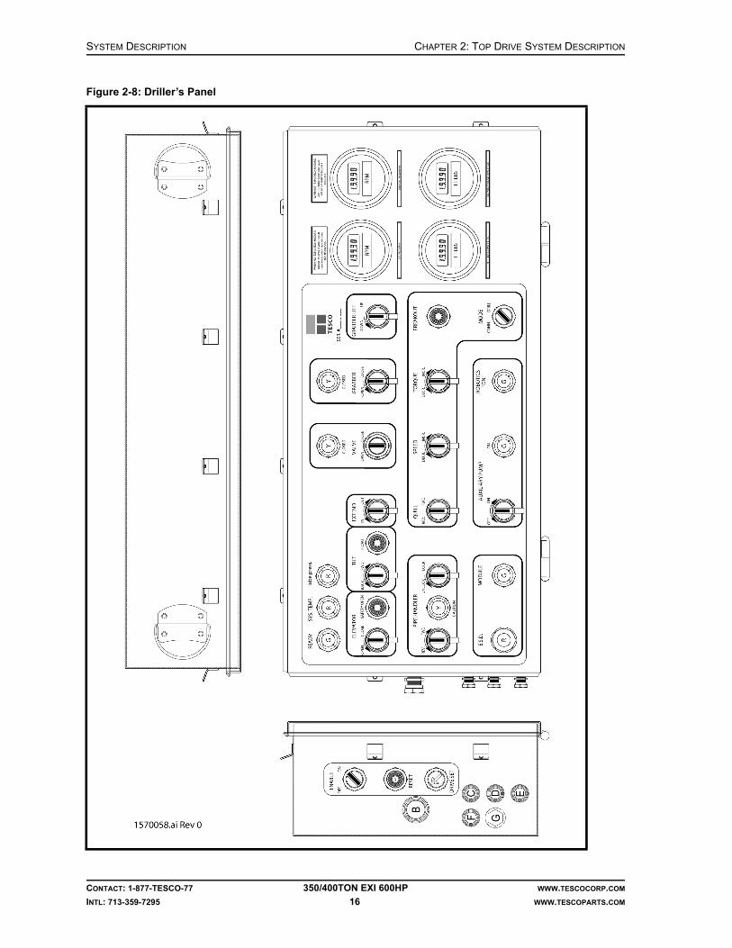
SYSTEM DESCRIPTION CHAPTER 2: TOP DRIVE SYSTEM DESCRIPTION
Figure 2-8: Driller’s Panel
CONTACT: 1-877-TESCO-77 350/400TON EXI 600HP WWW.TESCOCORP.COM
INTL: 713-359-7295 16 WWW.TESCOPARTS.COM

CHAPTER 2: TOP DRIVE SYSTEM DESCRIPTION SYSTEM DESCRIPTION
SHIPPING CONTAINERS
The EXI Top Drive System is typically shipped in standard 20 ft sea containers. Each container is 20 ft (length) × 8 ft (width) × 8 ft 6 in. (height) (6.1 m × 2.4 m × 2.6 m).
Container 1
Contents:
• top drive in a travel stand• links• counterbalance system• accessories
Container 2
Contents:
• power module • hydraulic power unit
Container 3
Contents:
• rig up kit• accessories• hose reel skid• spare parts
Note: Some countries require that spare parts be shipped separately from the original equipment. In these cases, spare parts will be crated and shipped in a separate container.
CONTACT: 1-877-TESCO-77 350/400TON EXI 600HP WWW.TESCOCORP.COM
INTL: 713-359-7295 17 WWW.TESCOPARTS.COM

SYSTEM DESCRIPTION CHAPTER 2: TOP DRIVE SYSTEM DESCRIPTION
OPTIONS
The following options are available. For more detailed information, contact a TESCO representative.
Elevators and Elevator Links
Automated elevators rated at 350 tons (318 tonnes), associated inserts for various drill pipe sizes, and accessories are available. A variety of link lengths is also available.
Additional Safety Valve and Actuator
Several sizes and thread types are available.
Subs
A complete selection of commonly used saver, casing, cross-over and drill collar handling subs is available. Non-standard subs can be manufactured if requested; delivery can be determined at time of order.
Grabber Drill Pipe Guides
These are used to guide the drill string into the grabber box. The drill pipe guide must match the box of the drill pipe in use. There is a range of sizes available.
Rotary Table Stabilizer Bushings
These urethane bushings fit the standard rotary table profile and protect the table and blowout preventer (BOP) from excessive wear. There is a range of sizes available.
Rotary Hose and Standpipe Extension
All equipment and accessories for these modifications are available.
Torque Arrest System
Optional equipment for non-standard and large mast torque arrest systems is available.
Alarms
The following optional alarm are available:
• extend alert features
CONTACT: 1-877-TESCO-77 350/400TON EXI 600HP WWW.TESCOCORP.COM
INTL: 713-359-7295 18 WWW.TESCOPARTS.COM

CHAPTER 2: TOP DRIVE SYSTEM DESCRIPTION SYSTEM DESCRIPTION
Driller’s Panel
Driller’s panel with hazardous area certification of II 2 G is available.
Power Supply Options
For installations where rig power reserves are not sufficient or where the power quality is low (surges, sudden shutdowns, etc.) TESCO can supply a stand-alone genset unit, powered by a diesel engine. The genset only supplies power to the top drive system allowing for greater power supply flexibility and reliability.
The genset comes is packaged in a modified 20-ft (6 m) sea container equipped with:
• doors and louvres, • optional space heater, • electric panels with plug boards, switches and breakers, • interconnection package.
Other Available Options
• air purge system for the driller's panel and top drive junction box.• workshop/parts containers with workbench and storage cupboards, complete with
interior lighting, optional stepdown transformer, power outlets and space heater.• video monitoring system, with cameras mounted in the derick at the monkey board
and crown levels.
A complete list of all available options and accessories is available from a local TESCO representative.
Table 2-7: Optional stand-alone genset
Imperial Metric
Rated power 1,020HP @ 1,800 rpm, 600VAC, 1,000A, 60Hz
Dimensions 20 ft (L) x 8 ft. (W) x 8 ft 6 in.(H)
6.1 x 2.4 x 2.6 m
Day tank capacity 80 gal 302.5 L
Rig Power 415VAC/3Ø or 220VAC/1Ø
CONTACT: 1-877-TESCO-77 350/400TON EXI 600HP WWW.TESCOCORP.COM
INTL: 713-359-7295 19 WWW.TESCOPARTS.COM

SYSTEM DESCRIPTION CHAPTER 2: TOP DRIVE SYSTEM DESCRIPTION
This page has been left blank intentionally.
CONTACT: 1-877-TESCO-77 350/400TON EXI 600HP WWW.TESCOCORP.COM
INTL: 713-359-7295 20 WWW.TESCOPARTS.COM

SYSTEM DESCRIPTION
ENGINEERING SIGN-OFF
This sign-off sheet indicates that this document has been approved for release by the Engineering Department at TESCO.
Document Complete By Signature Date Signed
Document Reviewed/Approved Date Signed
CONTACT: 1-877-TESCO-77 350/400 TON EXI 600HP WWW.TESCOCORP.COM
INTL: 713-359-7295 21 WWW.TESCOPARTS.COM
chane
Typewritten Text
Edward ChanSept. 28, 2009
chane
Typewritten Text
madejskm
Typewritten Text
Oct 22, 2009

SYSTEM DESCRIPTION
This page has been left blank intentionally.
CONTACT: 1-877-TESCO-77 350/400 TON EXI 600HP WWW.TESCOCORP.COM
INTL: 713-359-7295 22 WWW.TESCOPARTS.COM

DOCUMENT NAME: 880077 REV 2
Installation Guide
EXI Top Drive System
350/400 TON EXI 600HP


COPYRIGHT AND DISCLAIMER INSTALLATION GUIDE
CONTACT: 1-877-TESCO-77 350/400 TON EXI 600HP WWW.TESCOCORP.COM
INTL: 713-359-7295 I WWW.TESCOPARTS.COM
Tesco Corporation ("TESCO") has made every effort to ensure that this document contains accurate and current information for the TESCO top drive, however, the document is intended to be used in conjunction with a complete training program and on-site supervision and TESCO does not warrant or guarantee that the information contained herein is either complete or accurate in every respect, and the reader hereby protects, indemnifies and holds harmless Tesco Corporation together with its directors, officers, employees and agents from and against all liability for personal injury, death or property damage to any person arising directly or indirectly from the use by the reader of the information contained in the document.
This equipment was filled at the factory with TESCO ULTREX™ brand fluids and greases. To ensure maximum performance and to avoid cross-contamination, we strongly recommend the continued usage of TESCO ULTREX™ lubricants, unless otherwise specified.
TESCO ULTREX™ is a trademark and TESCO® is a registered trademark of Tesco Corporation.
Tesco Corporation © 2009
Contact Information
Corporate Head Office3993 W. Sam Houston Parkway No., Suite 100
Houston, Texas, 77043USA
www.tescocorp.comwww.tescoparts.com
Telephone: (713) 359-7000Fax: (713) 359-7001
After Market Sales and Service ContactToll Free North America: 1-877-TESCO-77
International: 713-359-7295

REVISION INFORMATION INSTALLATION GUIDE
CONTACT: 1-877-TESCO-77 350/400 TON EXI 600HP WWW.TESCOCORP.COM
INTL: 713-359-7295 II WWW.TESCOPARTS.COM
Revision Information
Version Date Description of Changes
Rev 0 August 2007 Initial Release
Rev 1 October 2008 Upgrade 350 EXI 600 to 350/400 EXI 600
Rev 2 September 2009 Added TESCO ULTREX™ recommendations and updated the footer to contain contact information.
TABLE OF CONTENTS INSTALLATION GUIDE
CONTACT: 1-877-TESCO-77 350/400 TON EXI 600HP WWW.TESCOCORP.COM
INTL: 713-359-7295 III WWW.TESCOPARTS.COM
TABLE OF CONTENTS
LIST OF FIGURES . . . . . . . . . . . . . . . . . . . . . . . . . . . . . . . . . . . . . . . . . . . . . . . . . . . . . V
LIST OF TABLES . . . . . . . . . . . . . . . . . . . . . . . . . . . . . . . . . . . . . . . . . . . . . . . . . . . . . VII
SAFETY INSTRUCTIONS . . . . . . . . . . . . . . . . . . . . . . . . . . . . . . . . . . . . . . . . . . . . . . . . IX
CHAPTER 1: ABOUT THIS DOCUMENT . . . . . . . . . . . . . . . . . . . . . . . . . . . . . . . . . . . . . . 1
CHAPTER 2: PRE-INSTALLATION ACTIVITIES . . . . . . . . . . . . . . . . . . . . . . . . . . . . . . . . . 3
Rig Installation and Measurement . . . . . . . . . . . . . . . . . . . . . . . . . . . . . . . . . . . . . . . . . . . . . . . . . . . . 3
Power/Service Connection Requirements . . . . . . . . . . . . . . . . . . . . . . . . . . . . . . . . . . . . . . . . . . . . . 3
Main Power Requirements (Rig AC Bus) . . . . . . . . . . . . . . . . . . . . . . . . . . . . . . . . . . . . . . . . . . . . . 5
Fuel Considerations . . . . . . . . . . . . . . . . . . . . . . . . . . . . . . . . . . . . . . . . . . . . . . . . . . . . . . . . . . . . . 5
Air Considerations . . . . . . . . . . . . . . . . . . . . . . . . . . . . . . . . . . . . . . . . . . . . . . . . . . . . . . . . . . . . . . 6
Safe Area Considerations. . . . . . . . . . . . . . . . . . . . . . . . . . . . . . . . . . . . . . . . . . . . . . . . . . . . . . . . . . . 6
Equipment Inspection (Pre-installation) . . . . . . . . . . . . . . . . . . . . . . . . . . . . . . . . . . . . . . . . . . . . . . . 6
CHAPTER 3: RIG UP PROCEDURE . . . . . . . . . . . . . . . . . . . . . . . . . . . . . . . . . . . . . . . . . 7
Equipment Placement. . . . . . . . . . . . . . . . . . . . . . . . . . . . . . . . . . . . . . . . . . . . . . . . . . . . . . . . . . . . . . 7
Optimal Placement of the Power Module and Auxiliary Hydraulic Power Unit . . . . . . . . . . . . . . . . . 7
How to Place the Power Module . . . . . . . . . . . . . . . . . . . . . . . . . . . . . . . . . . . . . . . . . . . . . . . . . . . 8
Optimal Placement of the Service Loop Reel. . . . . . . . . . . . . . . . . . . . . . . . . . . . . . . . . . . . . . . . . . 9
Optimal Placement of the Cable/Hose Saddle . . . . . . . . . . . . . . . . . . . . . . . . . . . . . . . . . . . . . . . . . 9
How to Install the Cable/Hose Saddle . . . . . . . . . . . . . . . . . . . . . . . . . . . . . . . . . . . . . . . . . . . . . . . 10
How to Install the Service Loop . . . . . . . . . . . . . . . . . . . . . . . . . . . . . . . . . . . . . . . . . . . . . . . . . . . . . 11
How to Install the Service Loop: Option 1 . . . . . . . . . . . . . . . . . . . . . . . . . . . . . . . . . . . . . . . . . . . 11
How to Install the Service Loop: Option 2 . . . . . . . . . . . . . . . . . . . . . . . . . . . . . . . . . . . . . . . . . . . 13
Torque Arrest System. . . . . . . . . . . . . . . . . . . . . . . . . . . . . . . . . . . . . . . . . . . . . . . . . . . . . . . . . . . . . 16
Before Installing the Torque Arrest System . . . . . . . . . . . . . . . . . . . . . . . . . . . . . . . . . . . . . . . . . . 16
Torque Arrest System Components . . . . . . . . . . . . . . . . . . . . . . . . . . . . . . . . . . . . . . . . . . . . . . . . 17
Torque Arrest System Configuration . . . . . . . . . . . . . . . . . . . . . . . . . . . . . . . . . . . . . . . . . . . . . . . 17
How to Determine the Torque Track Configuration (where an application drawing is not supplied) . . . . . . . . . . . . 18
Sample Calculation . . . . . . . . . . . . . . . . . . . . . . . . . . . . . . . . . . . . . . . . . . . . . . . . . . . . . . . . . 19
How to Install the Torque Arrest System . . . . . . . . . . . . . . . . . . . . . . . . . . . . . . . . . . . . . . . . . . . . 19
Top Drive . . . . . . . . . . . . . . . . . . . . . . . . . . . . . . . . . . . . . . . . . . . . . . . . . . . . . . . . . . . . . . . . . . . . . . . 23
How to Install the EXI 600 Top Drive . . . . . . . . . . . . . . . . . . . . . . . . . . . . . . . . . . . . . . . . . . . . . . . 23
Extend Arm Adjustment Procedure . . . . . . . . . . . . . . . . . . . . . . . . . . . . . . . . . . . . . . . . . . . . . . . . 27
Driller’s Panel . . . . . . . . . . . . . . . . . . . . . . . . . . . . . . . . . . . . . . . . . . . . . . . . . . . . . . . . . . . . . . . . . . . 28
How to Install the Driller’s Panel. . . . . . . . . . . . . . . . . . . . . . . . . . . . . . . . . . . . . . . . . . . . . . . . . . . 28
Safety Air Interlocks . . . . . . . . . . . . . . . . . . . . . . . . . . . . . . . . . . . . . . . . . . . . . . . . . . . . . . . . . . . . . . 29
About the Mud Pump Interlock . . . . . . . . . . . . . . . . . . . . . . . . . . . . . . . . . . . . . . . . . . . . . . . . . . . . 30

INSTALLATION GUIDE TABLE OF CONTENTS
CONTACT: 1-877-TESCO-77 350/400 TON EXI 600HP WWW.TESCOCORP.COM
INTL: 713-359-7295 IV WWW.TESCOPARTS.COM
Counter-Balance System. . . . . . . . . . . . . . . . . . . . . . . . . . . . . . . . . . . . . . . . . . . . . . . . . . . . . . . . . . .30
How to Set the Counter-Balance Cushion Height . . . . . . . . . . . . . . . . . . . . . . . . . . . . . . . . . . . . . .31
CHAPTER 4: SYSTEM INSPECTION AND START UP . . . . . . . . . . . . . . . . . . . . . . . . . . . . .33
Inspection-General Notes . . . . . . . . . . . . . . . . . . . . . . . . . . . . . . . . . . . . . . . . . . . . . . . . . . . . . . . . . .33
Warnings. . . . . . . . . . . . . . . . . . . . . . . . . . . . . . . . . . . . . . . . . . . . . . . . . . . . . . . . . . . . . . . . . . . . . . . .34
Electrical . . . . . . . . . . . . . . . . . . . . . . . . . . . . . . . . . . . . . . . . . . . . . . . . . . . . . . . . . . . . . . . . . . . . .34
Supply Power and Grounding . . . . . . . . . . . . . . . . . . . . . . . . . . . . . . . . . . . . . . . . . . . . . . . . . . . .34
Other . . . . . . . . . . . . . . . . . . . . . . . . . . . . . . . . . . . . . . . . . . . . . . . . . . . . . . . . . . . . . . . . . . . . . . . .36
System Start Up . . . . . . . . . . . . . . . . . . . . . . . . . . . . . . . . . . . . . . . . . . . . . . . . . . . . . . . . . . . . . . . . . .36
Table of Circuit Breakers and Main Breakers . . . . . . . . . . . . . . . . . . . . . . . . . . . . . . . . . . . . . . . . .37
Support Systems . . . . . . . . . . . . . . . . . . . . . . . . . . . . . . . . . . . . . . . . . . . . . . . . . . . . . . . . . . . . . . .37
How to Start the Generator (if supplied) . . . . . . . . . . . . . . . . . . . . . . . . . . . . . . . . . . . . . . . . . . . . . .37
Top Drive. . . . . . . . . . . . . . . . . . . . . . . . . . . . . . . . . . . . . . . . . . . . . . . . . . . . . . . . . . . . . . . . . . . . .38
Preliminary Checks and ESD Shutdown Test . . . . . . . . . . . . . . . . . . . . . . . . . . . . . . . . . . . . . . . . . . .38
How to Apply 600 VAC Transformer Power . . . . . . . . . . . . . . . . . . . . . . . . . . . . . . . . . . . . . . . . . . . .38
Power up the Drive System . . . . . . . . . . . . . . . . . . . . . . . . . . . . . . . . . . . . . . . . . . . . . . . . . . . . .39
How to Check Phase Rotation . . . . . . . . . . . . . . . . . . . . . . . . . . . . . . . . . . . . . . . . . . . . . . . . . . .39
How to Check the Hydraulic System . . . . . . . . . . . . . . . . . . . . . . . . . . . . . . . . . . . . . . . . . . . . . . . .40
How to Test the ESD on the Driller’s Panel . . . . . . . . . . . . . . . . . . . . . . . . . . . . . . . . . . . . . . . . . . . .41
Final Start Up . . . . . . . . . . . . . . . . . . . . . . . . . . . . . . . . . . . . . . . . . . . . . . . . . . . . . . . . . . . . .41
How to Reset the ACS800 Drive . . . . . . . . . . . . . . . . . . . . . . . . . . . . . . . . . . . . . . . . . . . . . . . . . . .41
Drive Parameters . . . . . . . . . . . . . . . . . . . . . . . . . . . . . . . . . . . . . . . . . . . . . . . . . . . . . . . . . . . . . .42
About Drive Parameters . . . . . . . . . . . . . . . . . . . . . . . . . . . . . . . . . . . . . . . . . . . . . . . . . . . . . . .42
How to Modify Drive Parameters . . . . . . . . . . . . . . . . . . . . . . . . . . . . . . . . . . . . . . . . . . . . . . . . . .42
CHAPTER 5: RIG OUT PROCEDURE. . . . . . . . . . . . . . . . . . . . . . . . . . . . . . . . . . . . . . . .45
Remove the Top Drive . . . . . . . . . . . . . . . . . . . . . . . . . . . . . . . . . . . . . . . . . . . . . . . . . . . . . . . . . . . . .45
Remove the Torque Arrest System . . . . . . . . . . . . . . . . . . . . . . . . . . . . . . . . . . . . . . . . . . . . . . . . . .46
Remove the Service Loop . . . . . . . . . . . . . . . . . . . . . . . . . . . . . . . . . . . . . . . . . . . . . . . . . . . . . . . . . .47
Disconnect the Power and Auxiliary Hydraulic Power Unit . . . . . . . . . . . . . . . . . . . . . . . . . . . . . . .50
APPENDIX A: PRE-INSTALLATION CHECKLIST . . . . . . . . . . . . . . . . . . . . . . . . . . . . . . . .51
APPENDIX B: VISUAL INSPECTION CHECKLISTS . . . . . . . . . . . . . . . . . . . . . . . . . . . . . . .53
APPENDIX C: SLING LOAD RATINGS . . . . . . . . . . . . . . . . . . . . . . . . . . . . . . . . . . . . . . .57
APPENDIX D: HAND SIGNALS FOR BOOM EQUIPMENT OPERATION. . . . . . . . . . . . . . . . .59
APPENDIX E: TRIP AND WARNING CODES . . . . . . . . . . . . . . . . . . . . . . . . . . . . . . . . . . .63
APPENDIX F: TORQUE STANDARDS FOR HIGH STRENGTH FASTENERS. . . . . . . . . . . . . .79
Purpose. . . . . . . . . . . . . . . . . . . . . . . . . . . . . . . . . . . . . . . . . . . . . . . . . . . . . . . . . . . . . . . . . . . . . . . . .79
Standards . . . . . . . . . . . . . . . . . . . . . . . . . . . . . . . . . . . . . . . . . . . . . . . . . . . . . . . . . . . . . . . . . . . . . . .79
Tables . . . . . . . . . . . . . . . . . . . . . . . . . . . . . . . . . . . . . . . . . . . . . . . . . . . . . . . . . . . . . . . . . . . . . . . . . .80
INDEX. . . . . . . . . . . . . . . . . . . . . . . . . . . . . . . . . . . . . . . . . . . . . . . . . . . . . . . . . . . . . .83
LIST OF FIGURES INSTALLATION GUIDE
CONTACT: 1-877-TESCO-77 350/400 TON EXI 600HP WWW.TESCOCORP.COM
INTL: 713-359-7295 V WWW.TESCOPARTS.COM
LIST OF FIGURES
Figure 2-1: Power connection with rig AC bus . . . . . . . . . . . . . . . . . . . . . . . . . . . . . . . . . . . . . . . . . . . 4Figure 2-2: Power connection with integrated generator. . . . . . . . . . . . . . . . . . . . . . . . . . . . . . . . . . . . 4Figure 3-1: EXI 600 optimal equipment placement . . . . . . . . . . . . . . . . . . . . . . . . . . . . . . . . . . . . . . . . 8Figure 3-2: EXI 600 hose saddle placement . . . . . . . . . . . . . . . . . . . . . . . . . . . . . . . . . . . . . . . . . . . . 10Figure 3-3: Installing the service loop through the mast structure. . . . . . . . . . . . . . . . . . . . . . . . . . . . 12Figure 3-4: Cable/hose saddle clamping location . . . . . . . . . . . . . . . . . . . . . . . . . . . . . . . . . . . . . . . . 13Figure 3-5: Front and end views of saddle, hose, and service loop . . . . . . . . . . . . . . . . . . . . . . . . . . 14Figure 3-6: EXI 600 cable/hose saddle capture clamp configuration . . . . . . . . . . . . . . . . . . . . . . . . . 14Figure 3-7: Hoisting the hose saddle. . . . . . . . . . . . . . . . . . . . . . . . . . . . . . . . . . . . . . . . . . . . . . . . . . 15Figure 3-8: Positioning the cable/hose saddle . . . . . . . . . . . . . . . . . . . . . . . . . . . . . . . . . . . . . . . . . . 15Figure 3-9: Torque arrest system configuration . . . . . . . . . . . . . . . . . . . . . . . . . . . . . . . . . . . . . . . . . 18Figure 3-10: Torque arrest system - portable installation . . . . . . . . . . . . . . . . . . . . . . . . . . . . . . . . . . 22Figure 3-11: Link locks in locked and unlocked position . . . . . . . . . . . . . . . . . . . . . . . . . . . . . . . . . . . 24Figure 3-12: EXI Top Drive capture clamp . . . . . . . . . . . . . . . . . . . . . . . . . . . . . . . . . . . . . . . . . . . . . 25Figure 3-13: Securing the auxiliary hydraulic hoses (350 EXI 600) . . . . . . . . . . . . . . . . . . . . . . . . . . 26Figure 3-14: Securing the auxiliary hydraulic hoses (400 EXI 600) . . . . . . . . . . . . . . . . . . . . . . . . . . 26Figure 3-15: Drawworks override installation . . . . . . . . . . . . . . . . . . . . . . . . . . . . . . . . . . . . . . . . . . . 29Figure 3-16: Counter-balance system interface . . . . . . . . . . . . . . . . . . . . . . . . . . . . . . . . . . . . . . . . . 30Figure 3-17: 350 EXI 600 counter-balance cushion height . . . . . . . . . . . . . . . . . . . . . . . . . . . . . . . . . 32Figure 3-18: 400 EXI 600 counter-balance cushion weight. . . . . . . . . . . . . . . . . . . . . . . . . . . . . . . . . 32Figure 4-1: Recommended supply power and grounding . . . . . . . . . . . . . . . . . . . . . . . . . . . . . . . . . . 35Figure 4-2: Change phase rotation . . . . . . . . . . . . . . . . . . . . . . . . . . . . . . . . . . . . . . . . . . . . . . . . . . . 40Figure 5-1: Setting the swivel link locks . . . . . . . . . . . . . . . . . . . . . . . . . . . . . . . . . . . . . . . . . . . . . . . 45Figure 5-2: Spooling the service loop 1. . . . . . . . . . . . . . . . . . . . . . . . . . . . . . . . . . . . . . . . . . . . . . . . 49

INSTALLATION GUIDE LIST OF FIGURES
CONTACT: 1-877-TESCO-77 350/400 TON EXI 600HP WWW.TESCOCORP.COM
INTL: 713-359-7295 VI WWW.TESCOPARTS.COM
This page has been left blank intentionally.

LIST OF TABLES INSTALLATION GUIDE
CONTACT: 1-877-TESCO-77 350/400 TON EXI 600HP WWW.TESCOCORP.COM
INTL: 713-359-7295 VII WWW.TESCOPARTS.COM
LIST OF TABLES
Table 1-1: Where to find more information . . . . . . . . . . . . . . . . . . . . . . . . . . . . . . . . . . . . . . . . . . .1
Table 4-1: Setting drive functions . . . . . . . . . . . . . . . . . . . . . . . . . . . . . . . . . . . . . . . . . . . . . . . . .43
Table B-1: Top drive inspection list . . . . . . . . . . . . . . . . . . . . . . . . . . . . . . . . . . . . . . . . . . . .53Table B-2: Power module inspection list . . . . . . . . . . . . . . . . . . . . . . . . . . . . . . . . . . . . . . . .54Table B-3: Auxiliary hydraulic power unit inspection list . . . . . . . . . . . . . . . . . . . . . . . . . . . .54Table B-4: Cable reel/service loop inspection list . . . . . . . . . . . . . . . . . . . . . . . . . . . . . . . . .55Table B-5: Driller’s panel. . . . . . . . . . . . . . . . . . . . . . . . . . . . . . . . . . . . . . . . . . . . . . . . . . . .55Table C-1: Maximum safe working loads (pounds). . . . . . . . . . . . . . . . . . . . . . . . . . . . . . . .57Table C-2: Rope diameter efficiencies . . . . . . . . . . . . . . . . . . . . . . . . . . . . . . . . . . . . . . . . .58Table D-1: Hand signals for boom operation . . . . . . . . . . . . . . . . . . . . . . . . . . . . . . . . . . . .59Table F-1: Standard torques . . . . . . . . . . . . . . . . . . . . . . . . . . . . . . . . . . . . . . . . . . . . . . . . .80Table F-2: Special fastener torques . . . . . . . . . . . . . . . . . . . . . . . . . . . . . . . . . . . . . . . . . . .81Table F-3: B7 Stud torques . . . . . . . . . . . . . . . . . . . . . . . . . . . . . . . . . . . . . . . . . . . . . . . . . .81Table F-4: Thread engagements. . . . . . . . . . . . . . . . . . . . . . . . . . . . . . . . . . . . . . . . . . . . . .81

INSTALLATION GUIDE LIST OF TABLES
CONTACT: 1-877-TESCO-77 350/400 TON EXI 600HP WWW.TESCOCORP.COM
INTL: 713-359-7295 VIII WWW.TESCOPARTS.COM
This page has been left blank intentionally.

SAFETY INSTRUCTIONS INSTALLATION GUIDE
CONTACT: 1-877-TESCO-77 350/400 TON EXI 600HP WWW.TESCOCORP.COM
INTL: 713-359-7295 IX WWW.TESCOPARTS.COM
SAFETY INSTRUCTIONS
Warning! Before operating and servicing this top drive system, always read and follow all safety instructions such as the warnings and cautions mentioned below and throughout the manual.
Top Drive System users risk injury to themselves and to others if the top drive is used improperly and/or safety precautions are not followed. TESCO advises personnel who work with or near the equipment to always wear proper personal protective equipment (PPE). Proper PPE consists of, but is not limited to, the following:
• hearing protection (ear defenders)• hard hat• safety glasses• steel toe shoes• fall protection when working above 6.5 ft (2 m), or the minimum height
requirement as directed by local jurisdiction.
Caution: This equipment is designed and certified for use in a hazardous environment. When maintenance requires replacement of parts, only identical parts can be used. Using alternate, non-iden-tical parts as a substitution may void compliance and certification.
Caution: Always perform the correct lock-out procedures as recommended by the Safety or Loss Prevention department before implementing maintenance.
Caution: Only authorized personnel can operate the top drive system.
Caution: This equipment can generate noise up to 90 decibels. Hearing protection suitable for this noise level must be worn when operating this equipment.
!
!
!
!
!

INSTALLATION GUIDE SAFETY INSTRUCTIONS
CONTACT: 1-877-TESCO-77 350/400 TON EXI 600HP WWW.TESCOCORP.COM
INTL: 713-359-7295 X WWW.TESCOPARTS.COM
Warning! Electrical voltages of different potentials are used throughout the TESCO top drive components (600 VAC, 208 VAC, 120 VAC, 840 VDC, 5-24 VDC). It is imperative that only qualified personnel install, maintain and/or troubleshoot the electrical systems. A severe hazard exists to personnel not accustomed to, or familiar with, electrical hazards and procedures.
Warning! There are high voltage capacitors installed in the ACS800 drive module. It is imperative that at least 5 minutes elapse, after power to the drive has been turned off, before any testing or repairs be undertaken at the module. The capacitors require time to ‘drain’ their stored electrical energy.
Warning! Accumulators used in the auxiliary hydraulic system are under the pressure of gas. Release this pressure before any maintenance is done on the auxiliary hydraulic system.
!
!
!

CHAPTER 1: ABOUT THIS DOCUMENT INSTALLATION GUIDE
CONTACT: 1-877-TESCO-77 350/400 TON EXI 600HP WWW.TESCOCORP.COM
INTL: 713-359-7295 1 WWW.TESCOPARTS.COM
CHAPTER 1: ABOUT THIS DOCUMENT
This document contains information on how to install the 350/400 TON EXI 600HP top drive, power module, auxiliary hydraulic power unit, torque arrest system, and service loop.
The installation sequence described in this document can be altered to accommodate current rig activity. The procedures described in this document provide instructions on how to do the following:
• perform a pre-installation assessment and equipment check• place equipment• install the service loop and connect services• install the torque arrest system• install the counter-balance system• install the top drive• connect the driller’s panel and safety interlocks• perform a system inspection and commission the unit• rig out
Table 1-1: Where to find more information
For information on Refer to
system components System Description
• setting torque and speed• driller's panel functions and operating descriptions• making connections• drilling ahead• tripping• freeing stuck pipe
Operations Guide
• load path inspections• maintenance/service schedules• component disassembly and reassembly
Maintenance Guide
TESCO manufactured parts and part numbers Parts List
• electrical schematics• hydraulic schematics• cooling schematics• gearbox lubrication schematics
System schematics
available options and spares TESCO representative

INSTALLATION GUIDE CHAPTER 1: ABOUT THIS DOCUMENT
CONTACT: 1-877-TESCO-77 350/400 TON EXI 600HP WWW.TESCOCORP.COM
INTL: 713-359-7295 2 WWW.TESCOPARTS.COM
This page has been left blank intentionally.

CHAPTER 2: PRE-INSTALLATION ACTIVITIES INSTALLATION GUIDE
CONTACT: 1-877-TESCO-77 350/400 TON EXI 600HP WWW.TESCOCORP.COM
INTL: 713-359-7295 3 WWW.TESCOPARTS.COM
CHAPTER 2: PRE-INSTALLATION ACTIVITIES
RIG INSTALLATION AND MEASUREMENT
To ensure that top drive installation progresses smoothly, complete a detailed rig measurement package before ordering equipment. Rig measurement packages are available from TESCO.
Accurate rig measurement helps do the following:
• Determine an equipment placement plan• Determine the best method for installing the top drive• Identify specialized equipment requirements, including the following:
• torque track hanging pad eye• cross-over or saver subs (top drive to drill string)• cable lengths and specific accessories• air/electric safety interlocks• torque arrest system components• cable/hose saddle mounting requirements• mud hose connection• standpipe extension
Ask a qualified TESCO representative to help complete the rig measurement package. This will ensure that the equipment will fit properly within the rig’s configuration.
POWER/SERVICE CONNECTION REQUIREMENTS
Discuss the following items with a qualified TESCO representative before requesting shipment of the top drive system:
• size and output of all generators• type and model of the distribution/SCR systems
The top drive system requires a 600 VAC, 1000A, 60Hz power supply. Where the power supply is 50Hz, an optional package can be installed during the manufacturing process, upon customer request. If the top drive unit is supplied with a generator, then the connection requirements for fuel and air should be considered.
The following figures illustrate the connection considerations to address before the top drive system arrives on location.

INSTALLATION GUIDE CHAPTER 2: PRE-INSTALLATION ACTIVITIES
CONTACT: 1-877-TESCO-77 350/400 TON EXI 600HP WWW.TESCOCORP.COM
INTL: 713-359-7295 4 WWW.TESCOPARTS.COM
Figure 2-1: Power connection with rig AC bus
Figure 2-2: Power connection with integrated generator

CHAPTER 2: PRE-INSTALLATION ACTIVITIES INSTALLATION GUIDE
CONTACT: 1-877-TESCO-77 350/400 TON EXI 600HP WWW.TESCOCORP.COM
INTL: 713-359-7295 5 WWW.TESCOPARTS.COM
Main Power Requirements (Rig AC Bus)
1. Determine a location for the power and mechanical modules.Note: If the rig configuration has not been finalized, then select two possible locations for the power module.
2. Determine where the main disconnect breaker panel will be located.Note: The best location provides room for service personnel and some shelter from the weather.
3. Determine the distance from the AC-Bus to the breaker panel.
4. Determine the distance from the breaker to the power module.
5. Determine if any special equipment is required. Examples: penetration or plug boards.
Note: This equipment is required if the three-phase power cables must pass through walls on their way from the main breaker to the power module.
6. Determine if cable tray or suitable space is available to accommodate three-phase power cables (from the breaker to the power module).
Note: If adequate space is not available, determine what materials would be required to protect the cables from the breaker to the power module.
7. If the customer is providing the main power supply (interconnection package), consult TESCO.
Fuel Considerations
If the top drive unit is supplied with a generator, then the connection requirements for fuel should be considered.
1. Determine the location and type of the fuel supply.Note: The fuel connector line should be 1 in. minimum, and it should be able to supply enough fuel for the power unit’s maximum consumption. The fuel return line should also be 1 in. minimum.
• For the Detroit Diesel 635 hp Genset, maximum consumption is 22.8 gallons per hour (86 liters per hour).
2. Determine the required length of the fuel line. Determine the route it will take from the fuel supply to the power unit.
Note: Avoid routing the fuel line where it might become damaged or pinched.
3. Verify the quality of the fuel supply.Note: Poor fuel quality might require special treatment. For example, fuel line heaters might be required in areas where diesel fuel contains high levels of paraffin.

INSTALLATION GUIDE CHAPTER 2: PRE-INSTALLATION ACTIVITIES
CONTACT: 1-877-TESCO-77 350/400 TON EXI 600HP WWW.TESCOCORP.COM
INTL: 713-359-7295 6 WWW.TESCOPARTS.COM
Air Considerations
If the top drive unit is supplied with a generator, then the connection requirements for air should be considered.
1. Determine if the air supply is adequate.Note: 100 psi (0.69 MPa) minimum with a 1 in. supply line
2. Verify the quality of the air supply.Note: If in an area with high humidity, then a moisture trap might be required to remove moisture from the starter’s air supply.
3. Determine the required length and route of the air supply line.Note: Avoid routing the line where it might become damaged or pinched. If placing the air receiver close to the power unit, this might help it start more easily.
SAFE AREA CONSIDERATIONS
The EXI 600 Top Drive System is provided with guards and suitable protection devices that comply with the Machinery Directive. Safety distances specified in EN294 must be maintained and a minimum IP20 ingress protection as specified in EN60529 must be ensured.
EQUIPMENT INSPECTION (PRE-INSTALLATION)
TESCO inspects all top drive equipment before shipping, however, some damage might occur while equipment is in transit.
It is important to identify any shipping damage as quickly as possible so that necessary repairs, ordering equipment replacements, and optimizing system readiness can be made..
As part of a pre-installation equipment inspection, do the following:
• Check all shipping containers for damage. External damage may indicate damage to contents.
• Visually inspect all principle components for damage or missing parts.• If the top drive system is shipped with fluid levels at full, check the fluid levels. Low
fluid levels may indicate a leak in the hydraulic, cooling, or lubrication system.
A sample equipment checklist is included in “Appendix A: Pre-Installation Checklist”.

CHAPTER 3: RIG UP PROCEDURE INSTALLATION GUIDE
CONTACT: 1-877-TESCO-77 350/400 TON EXI 600HP WWW.TESCOCORP.COM
INTL: 713-359-7295 7 WWW.TESCOPARTS.COM
CHAPTER 3: RIG UP PROCEDURE
EQUIPMENT PLACEMENT
Optimal Placement of the Power Module and Auxiliary Hydraulic Power Unit
Placement of the power module and hydraulic power unit is similar regardless of whether the power is supplied by the rig or by an independent generator. The following diagram shows the optimal placement of the power module and auxiliary hydraulic power unit. This placement is considered ideal for the following reasons:
• The distance from the main disconnect breaker to the power module is short.• The placement allows straight-line access from the cable reel to the cable/hose saddle.• The power module is in the aft position (closest to the generators).• The service loop cable connections are outboard of the rig.
Note: Excess service loop cable can be easily secured on the roof of the power module when it is in this position.
• There is easy access to the power module waterfall.• The auxiliary hydraulic power unit is placed close to the power unit and the connections
of the auxiliary hydraulic hose are easily accessible.• Easy access is provided around the power module and auxiliary hydraulic power unit for
operational and service activities.

INSTALLATION GUIDE CHAPTER 3: RIG UP PROCEDURE
CONTACT: 1-877-TESCO-77 350/400 TON EXI 600HP WWW.TESCOCORP.COM
INTL: 713-359-7295 8 WWW.TESCOPARTS.COM
Although the location of the power module depends on the rig configuration, the factors listed above should be considered when placing equipment.
How to Place the Power Module
1. Ensure the ground surface is level; remove any major obstructions.
2. Install rig matting or another secure material under the equipment location. Note: Ensure the rig matting extends far enough beyond the equipment to provide a walkway for outside service activity.
3. Using a crane or loader, place the power module on the rig matting.
4. Move the auxiliary hydraulic power unit to a location within 30 ft (9.1 m) of the power module.
5. Connect the following cords from the auxiliary hydraulic power unit to the incoming cable panel on the power module:• 1 x Power cable• 1 x Sensor cable
6. Connect the auxiliary hydraulic power module to the hose reel motor.
Figure 3-1: EXI 600 optimal equipment placement

CHAPTER 3: RIG UP PROCEDURE INSTALLATION GUIDE
CONTACT: 1-877-TESCO-77 350/400 TON EXI 600HP WWW.TESCOCORP.COM
INTL: 713-359-7295 9 WWW.TESCOPARTS.COM
Optimal Placement of the Service Loop Reel
The service loop reel acts as a spooling and storage device for electrical cables and auxiliary hydraulic hoses; it is not required during top drive operations.
Note: It is essential to unspool all of the cables from the service loop reel before operating the top drive.
After the hoses and cables are moved onto the saddle and connected to the power unit and top drive, the hose reel can be moved from the installation location to any convenient storage area.
“Figure 3-1: EXI 600 optimal equipment placement” shows the optimal location for the hose reel during installation of the service loop. This position is considered optimal for the following reasons:
• There is a clear view of the cable/hose saddle.• There is straight-line access from the hose reel to the cable/hose saddle.
Although the placement indicated on the illustration is considered optimal, placement of the reel is determined by the available space on site. Always ensure that the selected path is free of sharp edges and corners that can damage the service loop.
Optimal Placement of the Cable/Hose Saddle
The following illustration shows the optimal placement of the cable/hose saddle. This placement is considered ideal because the cable/hose saddle is situated as follows:
• High enough to prevent cables from landing on the rig floor when top drive is lowered:• If the mast is 100 to 125 ft (30.5 to 38.1 m), it is 55 to 65 ft (16.8 to 19.8 m) above the
rig floor.• If the mast height is 130 to 145 ft (39.6 to 44.2 m), it is 75 to 85 ft(22.9 to 25.9 m)
above the rig floor.• Low enough to allow the top drive to reach the rig floor without straining or damaging
cables.• Where there is straight-line cable access from the power unit.
Note: This position is a low activity area for overhead equipment. Accidental dam-age to cables is less likely to occur when the roller saddle is placed here.
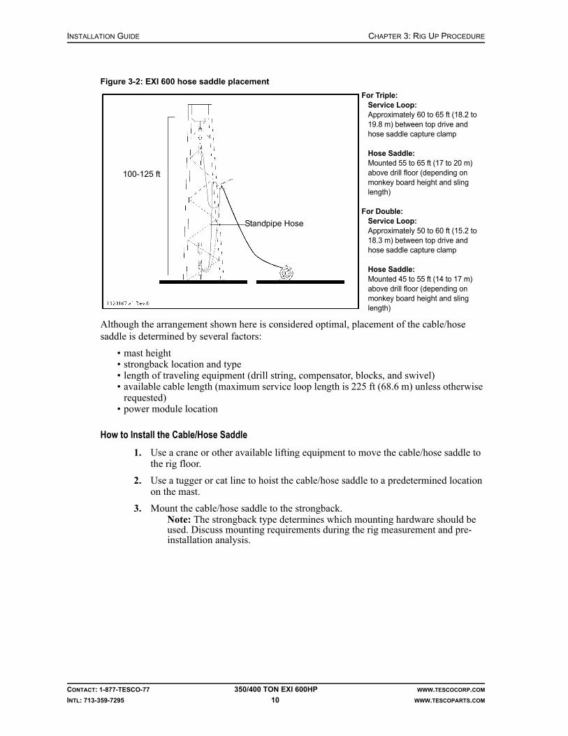
INSTALLATION GUIDE CHAPTER 3: RIG UP PROCEDURE
CONTACT: 1-877-TESCO-77 350/400 TON EXI 600HP WWW.TESCOCORP.COM
INTL: 713-359-7295 10 WWW.TESCOPARTS.COM
Although the arrangement shown here is considered optimal, placement of the cable/hose saddle is determined by several factors:
• mast height• strongback location and type• length of traveling equipment (drill string, compensator, blocks, and swivel)• available cable length (maximum service loop length is 225 ft (68.6 m) unless otherwise
requested)• power module location
How to Install the Cable/Hose Saddle
1. Use a crane or other available lifting equipment to move the cable/hose saddle to the rig floor.
2. Use a tugger or cat line to hoist the cable/hose saddle to a predetermined location on the mast.
3. Mount the cable/hose saddle to the strongback.Note: The strongback type determines which mounting hardware should be used. Discuss mounting requirements during the rig measurement and pre-installation analysis.
Figure 3-2: EXI 600 hose saddle placement
For Triple:Service Loop:Approximately 60 to 65 ft (18.2 to 19.8 m) between top drive and hose saddle capture clamp
Hose Saddle:Mounted 55 to 65 ft (17 to 20 m) above drill floor (depending on monkey board height and sling length)
For Double:Service Loop:Approximately 50 to 60 ft (15.2 to 18.3 m) between top drive and hose saddle capture clamp
Hose Saddle:Mounted 45 to 55 ft (14 to 17 m) above drill floor (depending on monkey board height and sling length)
Standpipe Hose
100-125 ft

CHAPTER 3: RIG UP PROCEDURE INSTALLATION GUIDE
CONTACT: 1-877-TESCO-77 350/400 TON EXI 600HP WWW.TESCOCORP.COM
INTL: 713-359-7295 11 WWW.TESCOPARTS.COM
HOW TO INSTALL THE SERVICE LOOP
There are typically two options to installing the service loop:
• Option 1: The service loop needs to be strung through the mast structure. This is typically done in a permanent installation.
• Option 2: The service loop is hung outside the mast structure and does not have to pass through the mast structure. The service loop is clamped to a cable/hose saddle and hoisted up beside the mast.
How to Install the Service Loop: Option 1
Use this procedure to string the service loop through the mast structure.
1. Ensure the auxiliary hydraulic lines are connected to the hose reel control.
2. Use a soft sling to bundle the ends of the cables and hoses of the service loop together.
3. Attach the bundle end to the cable of the floor tugger or loader.
4. Use the hose reel and tugger to lay out the length of the service loop that will travel with the top drive.
5. Measure and mark the length of the service loop that will hang from the hose saddle to the top drive starting at the hose or cable ends. Keep the service loop tidy and ensure the ends of all the hydraulic hoses and cables are as even with each other as possible.
6. Insert the hoses and cables in the cable/hose saddle capture clamp and tighten the clamp. Refer to Figure 3-6 on page 14 for the positions where the cables and hoses must be inserted.
7. Attach a tugger line to the cable/hose saddle, refer to Figure 3-3.
8. String a second tugger line through the mast structure where the service loop should go through the mast structure (point A on Figure 3-3) and attach this tugger line to the service loop about a third of the length between the service loop end and the cable/hose saddle (point B on Figure 3-3).
9. Hoist both the tugger lines at the same time. Hoist the cable/hose saddle as high as possible. At some point the service loop will get hoisted through the mast structure.
Note: Take care so that the service loop does not get snagged in the mast structure.
At this point the free end of the service loop should hang free in the mast.
10. Lower the tugger attached to the free end of the service loop until the service loop hangs from the cable/hose saddle.

INSTALLATION GUIDE CHAPTER 3: RIG UP PROCEDURE
CONTACT: 1-877-TESCO-77 350/400 TON EXI 600HP WWW.TESCOCORP.COM
INTL: 713-359-7295 12 WWW.TESCOPARTS.COM
11. Lower both the tuggers until the hose saddle is positioned where it is attached to the mast (usually it is at the racking board).
Figure 3-3: Installing the service loop through the mast structure

CHAPTER 3: RIG UP PROCEDURE INSTALLATION GUIDE
CONTACT: 1-877-TESCO-77 350/400 TON EXI 600HP WWW.TESCOCORP.COM
INTL: 713-359-7295 13 WWW.TESCOPARTS.COM
12. Install the hanging slings for the cable/hose saddle to the pad eyes with a shackle, or wrap it around a suitable beam, refer to Figure 3-8.
13. Use a shackle to attach the cable/hose saddle to the hanging slings.Note: The hanging slings must be strong enough to hold the loads of more than 2,000 lb (907.2 kg).
14. Lower the tugger attached to the cable/hose saddle further until the weight transfers to the hanging sling.
15. Install a back-up safety sling around the hose saddle
Caution: This back up sling is considered critical safety equipment.
16. Disconnect the tuggers from the service loop. The service loop is now ready to connect to the top drive.
How to Install the Service Loop: Option 2
Use this option when the service loop does not need to be strung through the mast structure.
1. Ensure that the auxiliary hydraulic fluid lines are connected to the hose reel control.
2. Use a soft sling to bundle the end of the service loop.
3. Attach the bundled end to the cable of the floor tugger or loader.
4. Use the hose reel and tugger to lay out the length of the service loop that will travel with the top drive.
5. Measure the length of the service loop, starting at the hose or cable ends. Keep the service loop tidy, and ensure the ends of all hydraulic hoses and cables are as even with each other as possible.
Note: When the hose saddle is in place, the hoses to the top drive should reach the rig floor, and approximately 3 ft (0.91 m) of hose should be lying on the floor.
Figure 3-4: Cable/hose saddle clamping location
1 - Cable and hose ends2 - Hose saddle
!

INSTALLATION GUIDE CHAPTER 3: RIG UP PROCEDURE
CONTACT: 1-877-TESCO-77 350/400 TON EXI 600HP WWW.TESCOCORP.COM
INTL: 713-359-7295 14 WWW.TESCOPARTS.COM
6. When the correct length has been spooled off the reel, insert the hoses and cable in the cable/hose saddle capture clamp.
7. Connect the cable/hose saddle to the cable of the floor tugger or crane.
Figure 3-5: Front and end views of saddle, hose, and service loop
Figure 3-6: EXI 600 cable/hose saddle capture clamp configuration

CHAPTER 3: RIG UP PROCEDURE INSTALLATION GUIDE
CONTACT: 1-877-TESCO-77 350/400 TON EXI 600HP WWW.TESCOCORP.COM
INTL: 713-359-7295 15 WWW.TESCOPARTS.COM
8. Hoist the saddle and hoses into position below the racking platform.Note: Hoist the saddle slightly higher than its final position.
9. Install the hanging sling for the cable/hose saddle at the racking platform.Note: Attach the hanging sling to the pad eye with a shackle, or wrap it around a suitable beam, refer to Figure 3-8.
10. Use a shackle to attach the cable/hose saddle to the hanging sling.Note: The cable/hose saddle sling must be strong enough to hold loads of more than 2,000 lb (907.2 kg).
11. Use the floor tugger or crane to lower the saddle until the weight transfers to the hanging sling.
Figure 3-7: Hoisting the hose saddle
Figure 3-8: Positioning the cable/hose saddle
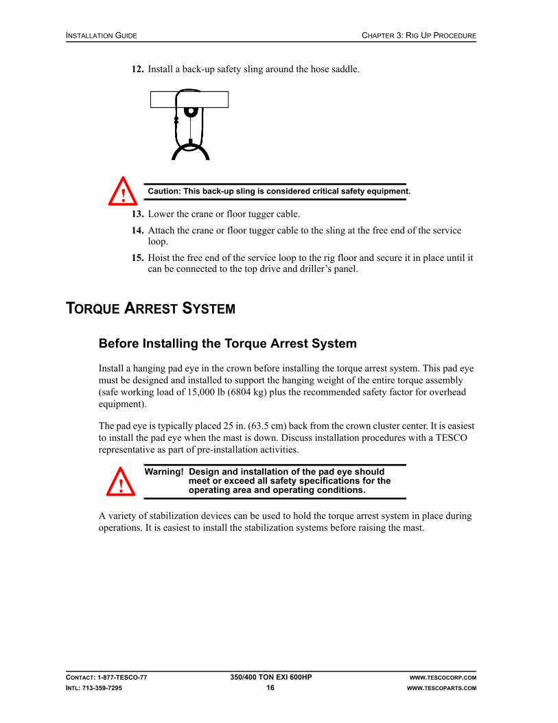
INSTALLATION GUIDE CHAPTER 3: RIG UP PROCEDURE
CONTACT: 1-877-TESCO-77 350/400 TON EXI 600HP WWW.TESCOCORP.COM
INTL: 713-359-7295 16 WWW.TESCOPARTS.COM
12. Install a back-up safety sling around the hose saddle.
Caution: This back-up sling is considered critical safety equipment.
13. Lower the crane or floor tugger cable.
14. Attach the crane or floor tugger cable to the sling at the free end of the service loop.
15. Hoist the free end of the service loop to the rig floor and secure it in place until it can be connected to the top drive and driller’s panel.
TORQUE ARREST SYSTEM
Before Installing the Torque Arrest System
Install a hanging pad eye in the crown before installing the torque arrest system. This pad eye must be designed and installed to support the hanging weight of the entire torque assembly (safe working load of 15,000 lb (6804 kg) plus the recommended safety factor for overhead equipment).
The pad eye is typically placed 25 in. (63.5 cm) back from the crown cluster center. It is easiest to install the pad eye when the mast is down. Discuss installation procedures with a TESCO representative as part of pre-installation activities.
Warning! Design and installation of the pad eye should meet or exceed all safety specifications for the operating area and operating conditions.
A variety of stabilization devices can be used to hold the torque arrest system in place during operations. It is easiest to install the stabilization systems before raising the mast.
!
!

CHAPTER 3: RIG UP PROCEDURE INSTALLATION GUIDE
CONTACT: 1-877-TESCO-77 350/400 TON EXI 600HP WWW.TESCOCORP.COM
INTL: 713-359-7295 17 WWW.TESCOPARTS.COM
Torque Arrest System Components
A standard torque arrest system includes the torque beam, T-bar, and the following torque track sections (typical). The number of torque track sections depends on the free working height of the mast and is shown on the application drawing supplied with the top drive system:
• one adjustable hanging sling• one cable clamp mount and cable capture clamp• one 18.5 ft (5.6 m) reversible, bolted, bottom torque track section• five 18.5 ft (5.6 m) standard torque track sections• one 10 ft (3.1 m) torque track section• one 5 ft (1.5 m) torque track section
Obtain additional length by lengthening the top section hanging sling. Purchase additional torque track sections to accommodate larger masts.
The following two sections of torque track are also included:
• one 1.3 ft (0.4 m) deflector section (bull nose)• one 2 ft (0.6 m) torque track section
Caution: Never subject these sections to torque. Mount them below the torque beam only.
The deflector section is always mounted at the bottom. Its tapered design assists in mounting the torque bushing onto the torque track.
Torque Arrest System Configuration
The following must be known before determining the torque track configuration:
• height of the hanging pad eye for the torque track, measured from the rig floor (A)• position (height above rig floor) where the torque beam and T-bar will be mounted (B)• length of the hanging assembly for the torque track, including hanging swivel, nut, and
shackles (2.5 ft minimum (0.8 m) to 15 ft (4.6 m) maximum)Note: Shorter configurations are safer and more practical.
Note: Correct calculations will help ensure that the torque bushing will not come off of the torque tube when the blocks are fully hoisted to the crown.
• the location of any upper strongback that may interfere with the vertical hanging of the torque track
Note: If the torque track is to remain in the mast during rig moves, match the torque track connections to the mast connections wherever possible.
!

INSTALLATION GUIDE CHAPTER 3: RIG UP PROCEDURE
CONTACT: 1-877-TESCO-77 350/400 TON EXI 600HP WWW.TESCOCORP.COM
INTL: 713-359-7295 18 WWW.TESCOPARTS.COM
How to Determine the Torque Track Configuration (where an application drawing is not supplied)
Sketch and calculate the following on paper before connecting sections of torque track.
1. Place the bottom of the deflector section 7 to 8 ft (2.1 to 2.4 m) above the drill floor (C).
2. Place the bottom bolted section of torque track above the deflector section.Note: Ensure that a suitable strongback for mounting the torque beam and T-bar is available somewhere along the length of the bolted section of torque track. Remember that the bolted section is reversible.
3. Stack the track sections (18.5 ft, 5 ft and 10 ft sections) until they are 5 to 15 ft (1.5 to 4.6 m) from the pad eye.
4. Determine the length of hanging assembly required.Note: Ensure that the length of hanging assembly is incorporated into the calculation.
5. Calculate the height of the torque bushing to ensure that it will not come off the top end of the torque track when it is in the uppermost position.
Figure 3-9: Torque arrest system configuration

CHAPTER 3: RIG UP PROCEDURE INSTALLATION GUIDE
CONTACT: 1-877-TESCO-77 350/400 TON EXI 600HP WWW.TESCOCORP.COM
INTL: 713-359-7295 19 WWW.TESCOPARTS.COM
Sample Calculation
If the mast height is 102 ft (31.1 m):
1. 102 ft less 7 ft (height above the rig floor for the deflector section) = 95 ft (29.0 m)
2. 95 ft less 2.5 ft (minimum hang sling length) = 92.5 ft (28.2 m)
3. 92.5 ft divided by 18.5 = five full length tubes; this does not include the deflector section.
Torque beam desired height = 11 ft (3.4 m)
The rig up would be as follows:
* The bolted track section would be run with the bolt section down, below the standard track sections and 10 ft (3 m) and 5 ft (1.5 m) sections. The deflector track section would be mounted below the bolted section.
How to Install the Torque Arrest System
Use this procedure to install the torque arrest track system. Refer to Figure 3-10 on page 22.
1. Ensure the hanging pad-eye for the torque track is installed in the crown.Note: Normal placement for a standard track is 25 in. back from the crown cluster center.
2. Assemble the torque beam, T-bar, and T-bar clamp.
Warning! Assemble the above with the T-bar at mid-length. This balances the assembly during lifting.The assembly should not be fully torqued, but it should hold the T-bar securely in place.
3. Use the tugger to move the torque beam onto the drill floor and up to the lowest, most practical strongback beam.
Note: Install the torque beam low in the mast. Attach it to a large beam anywhere between 10 ft (3 m) and 16 ft (4.9 m) above the drill floor. If it is installed any higher, additional stabilization below the torque beam might be required. TESCO can supply additional stabilization, if required.
4. Use four clamps to mount the torque beam to the selected supporting beam.Note: On a permanent installation, the anchor beam clamp can be weld onto the mast.
Track Part Qty Length (ft) Total Length (ft)
Hanging Track 1 18.5 18.5
Standard Tracks 2 37 (18.5 x 2) 55.5
10 ft section 1 10 65.5
5 ft section 1 5 70.5
Bolted* section 1 18.5 89
Deflector 1 1.3 90.3
Hanging Assembly 1 Set to 3 feet 90.3
!

INSTALLATION GUIDE CHAPTER 3: RIG UP PROCEDURE
CONTACT: 1-877-TESCO-77 350/400 TON EXI 600HP WWW.TESCOCORP.COM
INTL: 713-359-7295 20 WWW.TESCOPARTS.COM
5. Slide the T-bar to the most rearward position.Note: Always mount the T-bar on top of the torque beam.
6. Use the calculation method described in “How to Determine the Torque Track Configuration (where an application drawing is not supplied)” on page 18 to calculate the required torque track section configuration.
Note: When the torque track is suspended, the bottom of the deflector section should be 7 to 8 ft (2.1 to 2.4 m) off the floor.
7. Adjust the hanging assembly to the appropriate length.• Hanging Assembly: Thread the cable of the hanging sling assembly through the
hole in the top of the top track section. Fasten the clamp plate to the cable at the appropriate location so the hanging sling assembly has the required length as determine in previous calculations.
Note: Torque sling bolt clamps to 230 ft-lb (312 N-m).
Note: When tightening the sling clamp bolts, ensure that the sling is compressed evenly along its length. It will take several repetitions to ensure that the clamping force is distributed evenly across all of the cable clamps.
Note: Use a soft sling to hold the sling in place so that it will be easily acces-sible when the torque track is lifted to the hanging pad eye.
8. Use the rig floor tuggers to hoist the first track section up to the floor.Note: On most rigs, two full-length sections of torque track can be assembled on the ground before being lifted to the rig floor. If the rig is very small, the torque track lengths should be brought to the rig floor one at a time.
Note: As the first section is installed, make up additional sections on the ground.
9. Lower the first track section through the rotary table or mousehole.Note: If the rotary table is too small to permit the torque track to pass through, use an alternate location on the rig floor. If no alternate location exists, mate the sections above the rig floor.
10. Lower the blocks and install two handling slings on the torque track handling assembly.
Note: Thread the slings through the block becket and attach them to the top track using the handling assembly for the torque track.
Caution: Attach the top section of track such that the top portion of track extends above the blocks. This allows the hanging assembly to reach the pad eye without crowning out the blocks.
11. Place a ratchet strap around the top of the blocks and thread it around the torque track.
12. Use the ratchet strap to pull the blocks and track together.Note: This immobilizes the track section and keeps it hanging vertically as it travels up the mast.
13. Hoist the blocks until they support the weight of the torque track.
14. Remove the floor tugger.
15. Hoist the blocks until the bottom of the first section is 8 ft (2.4 m) above the drill floor.
16. Connect the floor tugger to the second section of torque track and hoist it to the rig floor.
17. Lower the second section of track through the rotary table or into the mousehole until it reaches the appropriate level for connecting to the upper section (which is currently suspended from the blocks).
!

CHAPTER 3: RIG UP PROCEDURE INSTALLATION GUIDE
CONTACT: 1-877-TESCO-77 350/400 TON EXI 600HP WWW.TESCOCORP.COM
INTL: 713-359-7295 21 WWW.TESCOPARTS.COM
18. Install all the studs and lower nuts before connecting the sections. Note: The studs cannot be installed after the track sections are connected.
19. Lower the blocks and upper section of track and connect the two sections. Bolt the sections together, ensuring a flush connection.
Note: Coat all studs with an anti-seize compound before installation.
20. Torque the studs to 350 ft-lb (475 N-m).
21. Repeat steps 16.–20. until all sections are connected and supported by the blocks.Note: The last section that is installed is typically composed of the reversible bolted section, the deflector section and, if required, the two-foot track section.
22. Use a ratchet strap to secure the extend arms of the torque bushing in place.
23. Attach a tugger to the torque bushing and move the bushing onto the drill floor.Note: Ensure that the extend frame is down.
24. Position the torque bushing over hole center.
25. Use the blocks to lower the assembled torque track and stab it through the torque bushing.
26. When the torque bushing is in position, pin it in place.Note: Ensure that the top drive pin ends are at least 8 ft (2.4 m) above the drill floor. If the torque bushing is too tight to move freely along the torque track, adjust the torque bushing by adding additional shim packs. To ensure a proper fit, periodically check the bushing during the first few days of operation.
27. After the torque bushing is installed, raise the blocks to the crown.
28. Connect the hanging assembly of the torque track to the pad eye.
29. When the hanging assembly is connected to the pad eye, lower the blocks until the weight of the track is transferred to the pad eye.
Note: Do not remove the handling assembly yet. Use the blocks to raise and lower the torque track while making the fine adjustments required to connect the T-bar to the bolted section.
30. Connect the T-bar to the bolted section of the torque track.
Caution: When connecting the bolted section of the torque track, ensure that the full weight of the torque track is suspended from the pad eye. If possible, mount it so the T-bar sits approximately 1/8 in. above the T-bar clamp so that the torque hanging assembly carries the total weight of the torque track.
Note: If the T-bar and bolted sections are not vertically aligned, then use the blocks to hoist the track. While the track weight is suspended from the blocks, adjust the hanging swivel as required. Up to 2 in. (5.1cm) of adjustment is available in the hanging assembly and the lock nut.
31. When all T-bar fastening bolts are tight, move the T-bar to the correct position in the T-bar seat and tighten the clamp to hold it in position.
Note: Hang the center of the torque track vertically, 25 in. (63 cm) back from the hole center.
32. Tighten the lock nut on the hanging assembly.
33. Remove the handling assembly at the crown and lower the blocks.
34. Install stabilization systems.Note: These are most easily installed when the mast is down, but can also be installed during rig-up.
35. Attach the stabilization devices to the torque track as shown in the following illustrations.
!

INSTALLATION GUIDE CHAPTER 3: RIG UP PROCEDURE
CONTACT: 1-877-TESCO-77 350/400 TON EXI 600HP WWW.TESCOCORP.COM
INTL: 713-359-7295 22 WWW.TESCOPARTS.COM
If the rig set-up requires a customized stabilization installation, contact TESCO.
Figure 3-10: Torque arrest system - portable installation
1 Torque track 7 Extend arms
2 3 way stabilizer 8 T-Bar
3 “F” clamp 9 T-Bar bolts
4 Nuts, washers, and Redi-rod 10 Torque anchor beam
5 Extend frame 11 Torque track (bolted section)
6 Torque bushing 12 Torque anchor beam clamps

CHAPTER 3: RIG UP PROCEDURE INSTALLATION GUIDE
CONTACT: 1-877-TESCO-77 350/400 TON EXI 600HP WWW.TESCOCORP.COM
INTL: 713-359-7295 23 WWW.TESCOPARTS.COM
TOP DRIVE
How to Install the EXI 600 Top Drive
Before moving the top drive onto the rig floor, ensure that the swivel yoke link with integral counter-balance is installed in the top drive and is securely supported by the top drive handling frame.
1. Using blocks or a crane, move the top drive to the rig floor.Note: If using the block, attach a hold-back line from the handling frame of the top drive to a loader or cat line tugger. Use the line to prevent the top drive from swinging when it is lifted off the rig floor.
Caution: Always attach the hoisting line to the top drive handling frame and not to any part of the top drive when the top drive is installed in the handling frame.
2. Position the top drive over the hole center.
3. Lower the blocks and remove the lifting sling.
4. Lower the blocks further and install the top drive yoke into the block hook or beckett.
5. Raise the blocks to support weight of the top drive.
Caution: Do not lift the top drive off the floor.
6. Remove yoke/link support pins. Rotate supports to allow yoke/link removal.
7. Remove the pins on the handling frame of the top drive (three or four in total, depending on the unit type).
Caution: Ensure the link lock turn buckles are set so that the top drive will not tilt forward. See Figure 3-11.
!
!
!

INSTALLATION GUIDE CHAPTER 3: RIG UP PROCEDURE
CONTACT: 1-877-TESCO-77 350/400 TON EXI 600HP WWW.TESCOCORP.COM
INTL: 713-359-7295 24 WWW.TESCOPARTS.COM
8. Lift the top drive until it is clear of the handling frame.
9. Use the floor tugger to remove the handling frame from the rig floor.
10. Use the blocks to position the top drive so that it can be joined to the extend frame. Align the ears on the top drive with the extend frame and extend arms and pin them in place.
11. Remove the pin that is holding the torque bushing in place on the torque track.Note: The weight of the top drive and torque bushing are now suspended from the blocks.
12. Unscrew the link lock turn buckles to remove the load, then unpin them and remove them to allow the links to swivel freely. Refer to Figure 3-11.
Caution: Ensure the top drive is pinned to the torque bushing before the link lock turn buckles are removed. The top drive will tilt forward if it is not pinned to the torque bushing.
13. Lower the top drive to the rig floor.
14. Check if the top drive hangs vertical. If not, refer to the “Extend Arm Adjustment Procedure” on page 27.
15. Reposition the T-bar so the top drive sits over the hole center, and secure it in place (if required). Refer to “Appendix F: Torque Standards for High Strength Fasteners” for the torque specification of the T-bar clamp bolts.
Figure 3-11: Link locks in locked and unlocked position
!

CHAPTER 3: RIG UP PROCEDURE INSTALLATION GUIDE
CONTACT: 1-877-TESCO-77 350/400 TON EXI 600HP WWW.TESCOCORP.COM
INTL: 713-359-7295 25 WWW.TESCOPARTS.COM
16. Tighten the T-bar connection to secure it in place. Refer to “Appendix F: Torque Standards for High Strength Fasteners”.
17. Locate the service loop. It should have been installed before this point. If the service loop has not been installed, see “How to Install the Service Loop: Option 1” on page 11 or “How to Install the Service Loop: Option 2” on page 13.
18. Clamp the following cables for the service loop to the top drive capture clamp. Allow enough cable to connect them to the top drive junction box.
Note: There should be no strain on the cables between the clamp and the motor junction box.
• one sensor cable• one robotics cable• one blower motor and heater cable• one ground cable• three motor power cables
19. Connect the cables to the receptacles on the top drive junction box or pigtails.
20. Connect the supply and return auxiliary hydraulic hoses to the quick connectors on the top drive.
21. Attach the kellum grips of the hoses to the 10-station manifold bracket, refer to Figure 3-13.
Note: The kellum grips must hold the weight of the hoses.
Figure 3-12: EXI Top Drive capture clamp

INSTALLATION GUIDE CHAPTER 3: RIG UP PROCEDURE
CONTACT: 1-877-TESCO-77 350/400 TON EXI 600HP WWW.TESCOCORP.COM
INTL: 713-359-7295 26 WWW.TESCOPARTS.COM
22. When all service loop hoses and cables are attached, check the loop position.• The loop should be off the floor.• There should not be any snagging/interference.
23. Re-check all hose connections.
24. Ensure that all required valves are open.
Figure 3-13: Securing the auxiliary hydraulic hoses (350 EXI 600)
Figure 3-14: Securing the auxiliary hydraulic hoses (400 EXI 600)

CHAPTER 3: RIG UP PROCEDURE INSTALLATION GUIDE
CONTACT: 1-877-TESCO-77 350/400 TON EXI 600HP WWW.TESCOCORP.COM
INTL: 713-359-7295 27 WWW.TESCOPARTS.COM
25. When the top drive and driller’s panel are connected, continue with additional set-up procedures, or begin rig commissioning.
Note: The counter-balance cushion height can be set after all support systems are running. The cushion height must be set before any drilling operations start. See “How to Set the Counter-Balance Cushion Height” on page 31.
Caution: After installation, ensure that safe access is provided to all areas on and around the top drive where adjustments and maintenance are necessary.
Extend Arm Adjustment Procedure
The aim of this procedure is to ensure that the top drive hangs vertical and is aligned with the hole center. Firstly, adjust the extend arms to ensure the top drive is vertical. Secondly, adjust the torque track to align the top drive with the hole center.
1. Start with the extend frame retracted in and a joint in the rotary table.
2. Move the grabber box up to the point where the bottom end of the saver sub is protruding through the grabber box.
3. Lower the top drive so that it is just above the joint in the rotary table (2 to 6 in).
4. Place a level on the top drive upper grabber leg to determine how the extend arms (extend or retract) will have to be adjusted. The top drive should hang vertically; if adjustment is required, loosen the jam nuts on the extend arm clevises.
5. Remove the lower extend arm pins.
Warning! Use a cat line to support the top drive so it does not tilt forward and to enable easy access and adjustment.
6. Adjust the arms appropriately by screwing the clevis in or out. This is a trial and error process that requires guesswork. Ensure the extend arms are equal length by measuring the distance from the end of the extend arm to the center of the pin hole in the clevis (allowable variance is + 1/16 in).
7. Hand tighten the jam nut and re-pin the extend arms to the extend frame mounts.
8. Visually inspect the level. If satisfactory, as judged by the level, continue to the next step. If the top drive is not satisfactorily level, repeat steps 4. through 8. until the top drive is vertical (this is a trial and error process and may take 3 to 4 adjustments before the top drive is vertical).
9. Torque the jam nuts appropriately (2,300 ft-lb/3,119 N-m dry, 1,725 ft-lb/2,339 N-m lubed) with a wrench and ensure the retaining cap screws are installed on the lower extend arm pins.
10. Visually inspect the alignment of the saver sub with the joint in the rotary table. If they are not aligned, adjust the torque track by adjusting the T-bar in the T-bar clamp.
Note: The torque track stabilizers must be adjusted accordingly to ensure the torque track hangs parallel to hole center.
!
!
INSTALLATION GUIDE CHAPTER 3: RIG UP PROCEDURE
CONTACT: 1-877-TESCO-77 350/400 TON EXI 600HP WWW.TESCOCORP.COM
INTL: 713-359-7295 28 WWW.TESCOPARTS.COM
DRILLER’S PANEL
How to Install the Driller’s Panel
The location selected for the driller’s panel should be as follows:
• within reach of the driller• where there is an unobstructed view of the top drive, rig floor, mast and travelling
equipment• where the driller has an unobstructed view of the robotic functions during operation• in a safe position• where there is sufficient lighting to clearly read all labels
The bottom of the driller’s panel is equipped with a four-bolt mounting plate. Use this to attach the control panel to a custom-built pedestal or existing framework. Some on-site fabrication of a mounting site might be required.
1. Locate the position for the driller’s panel.
2. Fabricate a mounting location if required.
3. Drill bolt holes in the mounting location.Note: A second mounting plate is provided to use as a template.
Caution: To avoid damaging components, avoid mounting the driller's panel in a location that is exposed to vibration.
4. Install the 4-twisted-pair control cable from the driller’s panel to the power module (cord B).
5. Mount the brake handle control box to the brake handle.
6. Connect the brake handle control box to the driller’s panel.Note: The driller’s panel has three labeled extension cords with military connectors. Use the correct cord (cord F).
!

CHAPTER 3: RIG UP PROCEDURE INSTALLATION GUIDE
CONTACT: 1-877-TESCO-77 350/400 TON EXI 600HP WWW.TESCOCORP.COM
INTL: 713-359-7295 29 WWW.TESCOPARTS.COM
SAFETY AIR INTERLOCKS
For detailed information about safety interlocks, refer to the schematics for the unit and/or contact a qualified TESCO representative.
How to Install the Drawworks Interlock and Override
The drum clutch interlock stops the air supply to the drum clutch so that the driller cannot hoist the top drive while the grabber is closed. Use the push button on the brake handle to override this lockout feature. The drawworks interlock override cannot be installed until the driller’s panel is in place.
1. Shut off the air supply from the compressor to the drum clutch control.Note: Use an isolator valve if necessary.
2. Disconnect the hose for the drum clutch air supply from the control valve.
3. Connect the air supply hose to an air/electric solenoid valve.Note: If two air supply hoses are present, connect each hose to an air/electric solenoid valve (one for low clutch and one for high clutch).
Figure 3-15: Drawworks override installation
1.Supply air2.Air/Electric solenoid valve3.Air line4.Drum clutch valve5.Air line6.Drawworks
7. Driller’s panel8. Grabber Open/Close switch9. Elevator button10.Grabber override button11.Control box for the brake handle

INSTALLATION GUIDE CHAPTER 3: RIG UP PROCEDURE
CONTACT: 1-877-TESCO-77 350/400 TON EXI 600HP WWW.TESCOCORP.COM
INTL: 713-359-7295 30 WWW.TESCOPARTS.COM
4. Connect the air supply from the air/electric solenoid valve to the drum clutch air control valve.
5. Connect an electric cable from the air/electric solenoid valve to the extension cord at the driller’s panel. The cord is labeled “Cord C”.
Note: If two air/electric solenoid valves are required, use a splitter to establish a connection from both valves to the driller’s panel.
6. Ensure the control box for the brake handle is connected to the driller’s panel.
About the Mud Pump Interlock
The mud pump air interlock is designed to prevent operation of the mud pump unless the mudsaver valve is open.
Before attempting to install this safety interlock, discuss equipment requirements and operational considerations with a qualified TESCO representative.
COUNTER-BALANCE SYSTEM
Figure 3-16: Counter-balance system interface
1. Accumulators: N2-Nitrogen and Oil
2. Counter-balance cylinder3. Needle Valve4. Auxiliary system
quick-coupler

CHAPTER 3: RIG UP PROCEDURE INSTALLATION GUIDE
CONTACT: 1-877-TESCO-77 350/400 TON EXI 600HP WWW.TESCOCORP.COM
INTL: 713-359-7295 31 WWW.TESCOPARTS.COM
How to Set the Counter-Balance Cushion Height
The following conditions must exist before the following portion of the counter-balance installation can be completed.
• The top drive must be installed.• The hydraulic circuit must be connected.• The driller’s panel must be operational.• The top drive must be positioned at the racking platform.
1. Connect the hose quick-coupler for the elevator to the charge fitting for the counter-balance system.
2. Shut off the auxiliary pump.
3. Open the needle valve on the counter-balance charge hose.
4. Set the ELEVATOR switch (at the driller’s panel) to ‘OPEN’, push and hold the ELEVATOR SAFETY–OPEN button.
Note: This allows the hydraulic fluid to drain from the counter balance cir-cuit.
5. Check the nitrogen pressure, and adjust to 1,200 psi (8.3 MPa) if required.
6. Ensure the counter-balance relief valve is set at 1,800 psi (12.4 MPa).Note: The relief valve on the CE/ATEX certified units are preset and cannot be adjusted.
7. Close the needle valve on the counter-balance charge hose
8. Start the auxiliary pump.
9. Set the ELEVATOR switch (driller’s panel) to ‘CLOSE’.Note: This will send 1,500 psi (10.3 MPa) hydraulic pressure to the needle valve on the counter-balance manifold.
10. Slowly open the needle valve and allow the hydraulic oil to charge the counter-balance system.
11. Monitor the counter-balance cushion by watching the gap that develops between the yoke pin and the top of the swivel link bore, refer to Figure 3-17.
12. Continue to charge the system until the gap is 1-1/2 in. to 2 in.
13. Close the needle valve.
14. Shut off the auxiliary pump.Note: This will allow the oil pressure in the auxiliary system to decrease.
15. Set the ELEVATOR switch to ‘OPEN’, then to ‘CLOSE’. This will relieve any pressure in the system.
16. Remove the elevator hydraulic hose from the counter-balance manifold.
Caution: If disconnecting a quick coupler while there is pressure in the system, it will be extremely difficult to reconnect the coupler.
!
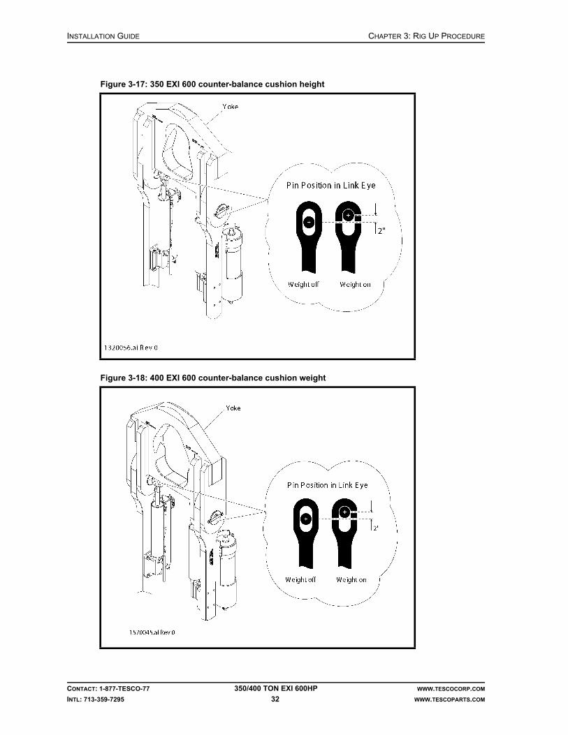
INSTALLATION GUIDE CHAPTER 3: RIG UP PROCEDURE
CONTACT: 1-877-TESCO-77 350/400 TON EXI 600HP WWW.TESCOCORP.COM
INTL: 713-359-7295 32 WWW.TESCOPARTS.COM
Figure 3-17: 350 EXI 600 counter-balance cushion height
Figure 3-18: 400 EXI 600 counter-balance cushion weight

CHAPTER 4: SYSTEM INSPECTION AND START UP INSTALLATION GUIDE
CONTACT: 1-877-TESCO-77 350/400 TON EXI 600HP WWW.TESCOCORP.COM
INTL: 713-359-7295 33 WWW.TESCOPARTS.COM
CHAPTER 4: SYSTEM INSPECTION AND START UP
INSPECTION-GENERAL NOTES
When the installation procedures are complete, perform a visual inspection of the complete system.
Caution: Perform visual inspections before applying power to the system.
Inspection checklists for the following are included in “Appendix B: Visual Inspection Checklists”.
• top drive• power module• auxiliary hydraulic power unit• control cables• power cables• driller’s panel
!

INSTALLATION GUIDE CHAPTER 4: SYSTEM INSPECTION AND START UP
CONTACT: 1-877-TESCO-77 350/400 TON EXI 600HP WWW.TESCOCORP.COM
INTL: 713-359-7295 34 WWW.TESCOPARTS.COM
WARNINGS
Electrical
If client-supplied power is not 600 VAC, 60 Hz, discuss necessary system changes with a qualified TESCO representative.
Danger! Electrical voltages of different potentials are used throughout the TESCO top drive components (600 VAC, 208 VAC, 120 VAC, 840VDC, 5–24VDC). ONLY qualified personnel should install, maintain, and/or troubleshoot the electrical systems. A severe safety hazard exists for personnel not accustomed to, or familiar with, electrical hazards and procedures.
Danger! There are high voltage capacitors installed in the ACS800 Variable Frequency Drive. Wait at least five minutes after disengaging power to the drive before performing any testing or repairs in the module. The capacitors require time to drain their stored electrical energy.
Supply Power and Grounding
Grounding methodology has always been a challenge because of differing interpretations of the rules and understanding of intent. On-site conditions, such as add-on buildings fed from a common power source or separate power sources not requiring a neutral conductor, all have specific grounding criteria that must be met. TESCO has strived to maintain a safe “standard” method of grounding so that its implementation becomes familiar to all personnel installing these systems.
The following is TESCO’s recommended grounding method when a ground fault detection system is not incorporated into the service supply.
TESCO incorporates a “single point” ground system when providing the power source to TESCO loads and/or add-on loads. Furthermore, when an “isolated” system (a power system that is not conductively connected to the distribution system, as in the case of separate generator but most commonly a transformer) is incorporated, it is intended that all ground paths be connected to the common ground electrode(s).
!
!

CH
AP
TE
R 4: S
YS
TE
M IN
SP
EC
TIO
N A
ND
ST
AR
TU
PIN
ST
ALLA
TIO
N G
UID
E
CO
NT
AC
T: 1-87
7-T
ES
CO
-77
350/400 TO
N E
XI 600H
PW
WW
.TE
SC
OC
OR
P.CO
M
INT
L: 713
-359
-729
535
WW
W.T
ES
CO
PA
RT
S.CO
M
It is imperative that the grounding methodology shown above be adhered to when using a designated generator as the main power service supply for the TESCO top drive system. Since the separate generator supplying power to the TESCO equipment does not incorporate a ground fault detection system (and whether the rig employs a ground fault detection system or not) it is required that the generator system neutral be grounded at one point only via the main ground bus and ground rods. When two or more power systems are employed, a “common system grounding conductor” shall be installed unless separate grounding is supplied for each such system, in which case the grounding for the individual systems shall be interconnected. Therefore, a separate ground cable must be installed between the rig's ground grid and the generator ground grid. Due to this “link”, the ground rods at the generator may be eliminated, but TESCO recommends that they remain.
Figure 4-1: Recommended supply power and grounding

INSTALLATION GUIDE CHAPTER 4: SYSTEM INSPECTION AND START UP
CONTACT: 1-877-TESCO-77 350/400 TON EXI 600HP WWW.TESCOCORP.COM
INTL: 713-359-7295 36 WWW.TESCOPARTS.COM
Other
• Ensure the gearbox breather is installed and the ball valve is opened prior to operating.Note: The breather may not be installed for shipping purposes and some new units may have the ball valve handle wired closed.
• Close the main breaker MB4 to turn the hydraulic tank heater on. When the temperature reaches 10ºC, the heating circuit will shut off automatically.
• Ensure that all electrical components are free of frost and condensation before system start up. Do this by opening all cabinet doors inside the power module and heating the building to at least 50F (10C) for eight hours. 208V power is required to operate the building HVAC unit.
• Install a saver sub in the grabber on the top drive before testing for hydraulic leaks or operate any robotics function.
Caution: The hydraulic pump cannot be started if the Emergency Shut Down (E.S.D.) is activated (either of two red buttons: one on the driller’s panel and one on the door of the main panel control system).
• Before starting any pumps, ensure that all appropriate valves on tanks and pumps are open.
SYSTEM START UP
After completing all visual inspections, begin the system start up process. This section provides instructions on how to do the following:
• power up support systems• power up the drive system• test the robotics functions and operations of the top drive
Danger! The information presented in this section is a guide ONLY. It is not intended to replace complete training on the use of high voltage equipment.
Note: Refer to the electrical schematics supplied with the unit.
!
!

CHAPTER 4: SYSTEM INSPECTION AND START UP INSTALLATION GUIDE
CONTACT: 1-877-TESCO-77 350/400 TON EXI 600HP WWW.TESCOCORP.COM
INTL: 713-359-7295 37 WWW.TESCOPARTS.COM
Table of Circuit Breakers and Main Breakers
Refer to the electrical schematics for the unit to confirm breaker details.
Support Systems
How to Start the Generator (if supplied)
1. Ensure that all fuel and air connections are secure.
2. Ensure that the following are set to ‘OFF’.• main service interface breaker• all main drive breakers in the power module building• all switches
3. Check all oil and coolant levels. Ensure the generator battery is above 22V.
4. Ensure that the following are clear of any obstructions or protective packing material:• radiator• air intakes• exhaust
5. Ensure all cabling and controls are in good operating condition (no noticeable damage).
6. Engage the air starter for one short burst without starting the engine.Note: This ensures the engine is free to roll over.
7. Set the controls to Start, and start the engine.
8. When the engine is running, check the oil pressure and rpm.
Caution: Ensure the oil pressure and rpm are within normal operating parameters.
CB (circuit breakers) - 120/208 VAC Distribution Panel
Breaker Type and Number Function
CB1 Power module lighting
CB2 120 VAC control power
CB3 Power module receptacles
CB4 24 VDC power supply
CB5 Spare
CB9 Motor heater
CB12/14/16 Power module HVAC
MB (main breakers)
Breaker Type and Number Function
MB1 ACS800 drive system power
MB2 Tie breaker
MB3 (in 600V distribution panel) 15kVA 600:120/208 VAC transformer
MB4 (in 600V distribution panel) Hydraulic tank heater
!

INSTALLATION GUIDE CHAPTER 4: SYSTEM INSPECTION AND START UP
CONTACT: 1-877-TESCO-77 350/400 TON EXI 600HP WWW.TESCOCORP.COM
INTL: 713-359-7295 38 WWW.TESCOPARTS.COM
9. Allow the engine to warm up.Note: The warm up time required varies depending on the ambient operating temperature.
10. Increase the rpm to the rated speed (1,800 rpm).
11. Engage the disconnect breaker for the main generator.Note: This applies only if the generator has its own service disconnect breaker and the system also incorporates a TESCO specified main service dis-connect (see step 13.).
12. Adjust the generator controls for frequency and voltage (600 VAC and 60 Hz).
13. Switch the main service disconnect breaker to ‘ON’ (if applicable). This is the TESCO specified main service disconnect that feeds the power module building.
Top Drive
Preliminary Checks and ESD Shutdown Test
1. Ensure all breakers in the power module are set to ‘OFF’.
2. Ensure that 600 VAC power is present at the main service interface breaker.
3. Verify that the Emergency Shut Down cable is connected and the E.S.D push buttons (on the driller’s panel and power module exterior, next to the door) are pulled out (off).
4. Switch the main service interface breaker to ‘ON’.
5. Ensure that 600 VAC power is present on the outgoing cables to the power module.Note: Check this on the terminal lugs in the Interface Breaker cabinet under the interface breaker.
6. Ensure that the ‘SERVICE BREAKER CLOSED’ indicator light for rig power is illuminated.
Note: The light is located on the door of the main panel in the power module building.
7. Push the E.S.D.push button to test the Emergency Shut Down circuit.
Caution: This should trip the main service interface breaker.
8. Re-set the E.S.D. push button and repeat steps 4.through 6.
How to Apply 600 VAC Transformer Power
Use this procedure to provide power for the lighting, receptacles, and controls (120/208V and 15/24VDC). The top drive start up procedure is the same whether using a generator supplied by TESCO or rig power.
1. Ensure that ALL breakers and switches for the power module are set to ‘OFF’.
2. Switch the main breaker MB3 to the ‘ON’ position.Note: This breaker energizes the transformer that provides power to the power module lighting, receptacles, and controls. Refer to the electrical schematics for the unit for more detailed information.
!

CHAPTER 4: SYSTEM INSPECTION AND START UP INSTALLATION GUIDE
CONTACT: 1-877-TESCO-77 350/400 TON EXI 600HP WWW.TESCOCORP.COM
INTL: 713-359-7295 39 WWW.TESCOPARTS.COM
3. Inside the 120/208V distribution panel, switch the following circuit breakers to the ‘ON’ position:• CB1 (power module lighting)• CB2 (120 VAC control power)• CB3 (power module receptacles)• CB4 (24 VDC power supply)• CB9 (motor heater)• CB12/14/16 (power module HVAC)
4. Set the light switch to the ‘ON’ position.Note: This switch is located on the wall of the power module .
5. Proceed to the following section: “Power up the Drive System”.
Power up the Drive System
1. Verify that the ESD on the driller’s panel is not activated.
2. Close the main breaker MB1 in the main drive cabinet to power up the drive system. To close MB1:• Ensure that the breaker switch is fully reset by pushing it down to the ‘OPEN’
position.• Push the breaker switch up to the ‘CLOSED’ position.
3. Push the blue RESET button on the front of the drive cabinet to clear any warning or faults in the drive.
4. On the left side of driller’s panel, turn the ENABLE switch to ‘OFF’.
5. Press the RESET button on the left side of driller’s panel to reset PLC communication.
6. Ensure that the green ‘READY’ light on the driller’s panel illuminates.
7. Proceed to the following section: “How to Check Phase Rotation”.
How to Check Phase Rotation
Use this procedure to ensure that the phase rotation is correct, and that all pumps, fans, and motors turn in the proper direction. Do not use pump motors to check phase rotation.
1. Switch motor starter 2M and 3M to ‘ON’.
2. Make sure all switches on driller’s panel are set to neutral position.
3. Turn the ENABLE switch to ‘ON’.
4. Set the ‘Set Speed’ and ‘Set Torque’ to zero using SPEED DECR and TORQUE DECR switch.
5. Ensure that the top drive is not rotating.
6. Ensure that the blower motor for the top drive rotates counter-clockwise when viewed from above.
7. Turn the QUILL switch back to neutral position.
8. If the direction of the blower motor is incorrect, do the following:
a. Shut off the main breaker MB1 and shut off the power at the main service breaker.

INSTALLATION GUIDE CHAPTER 4: SYSTEM INSPECTION AND START UP
CONTACT: 1-877-TESCO-77 350/400 TON EXI 600HP WWW.TESCOCORP.COM
INTL: 713-359-7295 40 WWW.TESCOPARTS.COM
b. At the power module (service supply waterfall), remove the feed cable(s) from phase A and B.
c. Install the phase A cable(s) into the phase B input(s).
d. Install the phase B cable(s) into the phase A input(s).
e. Retest to verify the fan is rotating in the correct direction (steps 1.to 7.).
f. Retag the cabling to the current (correct) configuration.
9. Proceed to the following section: “How to Check the Hydraulic System”, below.
How to Check the Hydraulic System
1. Install a saver sub in the grabber on the top drive.
Caution: Never close the grabber unless there is a saver sub or tool joint for it to close on. Closing the grabber when it is empty severely damages the grabber cylinder.
Caution: Install a saver sub to prevent the piston on the grabber cylinder from making contact with the gland nut on the grabber cylinder body. When this happens, the gland nut is pushed out of the cylinder body.
2. In the 600 VAC distribution panel, set the starter 3M for the auxiliary pump to ‘ON’.
3. Set the switch on the driller’s panel for the auxiliary pump to ‘ON’.
The green light should illuminate.
4. Check and record the circulating pressure (it should be 400-600 psi at normal operating temperature).
5. Inspect the lines for leaks.
6. Shut off the auxiliary pump.
7. Check the auxiliary tank level and fill it, if required.Note: Oil from the top drive hydraulic lines returns to the tank when the system is idle. This might cause tanks to appear over-full. Check the fluid levels before starting the system and when the system is running.
IMPORTANT: This equipment was filled at the factory with TESCO ULTREX™ brand fluids and greases. To ensure maximum performance and to avoid cross-contamination, we strongly recommend the continued usage of TESCO ULTREX lubricants, unless otherwise specified.
Figure 4-2: Change phase rotation
Phase Input A
Phase Input B
Phase Input C
A
B
C
Original
B
A
C
Change to
!
!

CHAPTER 4: SYSTEM INSPECTION AND START UP INSTALLATION GUIDE
CONTACT: 1-877-TESCO-77 350/400 TON EXI 600HP WWW.TESCOCORP.COM
INTL: 713-359-7295 41 WWW.TESCOPARTS.COM
How to Test the ESD on the Driller’s Panel
When activated, the ESD on the driller’s panel will trip the main breaker MB1 (which feeds the drive system) and turn off the auxiliary hydraulic pump.
1. Verify the main breaker MB1 is closed and the hydraulic pump is ‘ON’.
2. Press the ESD on the driller’s panel.
3. Verify that the main breaker MB1 has tripped.
4. Verify that the hydraulic pump has been turned off.
5. To reset the ESD, pull the button to the ‘UP’ position.
Final Start Up
When all critical systems are started and operating properly, the top drive can be started.
Before proceeding, confirm that all the following systems are operating correctly:
• cooling fans on the ACS800 drive cabinets• blower motor on the top drive
After confirming that all systems are operating correctly, perform the following steps:
1. Ensure that the ACS800 drive keypad display does not show any warnings or faults.
2. Check the indicators on the driller’s panel. The following lights should be on:• Ready• Module On
3. At the driller’s panel, set the ENABLE switch to ‘ON’.
4. Check the rotation and torque (at low settings) to confirm proper operation.
Caution: If using a customer-supplied swivel, it will not be properly connected to the top drive. Conduct operational checks at very low rpm, and only in the Forward setting. If rotating in reverse when the swivel is not fully connected, the swivel might unscrew at the connection with the top drive (and the top drive may fall to the rig floor).
How to Reset the ACS800 Drive
Use the following procedure if the ACS800 Drive System trips “off line” because an internal protection system has been activated. This procedure assumes that the system has sustained no damage and that supply power of 600 VAC is present.
1. Set all switches on the driller’s panel to the neutral position.
2. Turn the ENABLE switch on the driller's panel to the ‘OFF’ position (disable).
3. Ensure the following:• The communication between PLC and drive works properly• The encoder cable is securely connected• The fans for the top drive blower and drive cabinets work properly
!

INSTALLATION GUIDE CHAPTER 4: SYSTEM INSPECTION AND START UP
CONTACT: 1-877-TESCO-77 350/400 TON EXI 600HP WWW.TESCOCORP.COM
INTL: 713-359-7295 42 WWW.TESCOPARTS.COM
4. Check the fault information shown on the drive keypad and refer to the “Fault Tracking” section on page 223 of the ACS800 Firmware manual.
5. Press the RESET button on the ACS800 drive to reset faults after the faulty conditions have been removed.
6. Return to the driller’s panel and turn the ENABLE switch to the ‘ON’ position. The green READY light will illuminate.
7. Continue with regular operations.
8. Attempt to determine why the unit tripped off line. Make note of all relevant drilling conditions that existed before the breakers tripped.
Drive Parameters
About Drive Parameters
The following drive parameters (torque and speed settings) can be modified from the driller’s panel:
• Drill Forward – Torque and Speed• Drill Reverse – Torque and Speed• Connect Forward – Torque and Speed• Connect Reverse – Torque and Speed• Breakout – Speed
Set the drive parameters (torque and speed) to minimize the possibility of injury to personnel and damage to drilling equipment. For example, limit the torque setting for Drill–Forward mode to prevent the drill string twisting off while drilling. Set the speed and torque for Connect mode to promote proper make up of tool joints and to prevent damage to threads and seal faces caused by over-torquing.
Limit the rotation speed and torque of the pipe handler to ensure the pipe handler rotates at a safe speed and stops rotating when it achieves the pre-set torque.
The drive system will not surpass the programmed torque and speed settings during operation. If the settings need to be changed, use the following procedure. The steps required to set or adjust a setting are the same for all functions.
How to Modify Drive Parameters
1. At the driller’s panel, turn the ENABLE switch to ‘OFF’.
2. Insert the key into the DRIVE SET keyed switch.
3. Turn and hold the key in the ‘SET’ position.
4. Select and set the required function using Table 4-1 on page 43.
5. Release the DRIVE SET keyed switch.
6. Remove the key.
7. Set the ENABLE switch to ‘ON’.

CHAPTER 4: SYSTEM INSPECTION AND START UP INSTALLATION GUIDE
CONTACT: 1-877-TESCO-77 350/400 TON EXI 600HP WWW.TESCOCORP.COM
INTL: 713-359-7295 43 WWW.TESCOPARTS.COM
Table 4-1: Setting drive functions
To set this Perform these steps
Drill Forward Torque
1. Set the MODE switch to ‘DRILL’. 2. Set the QUILL switch to ‘FWD’. 3. Use the TORQUE switch to increase or decrease the SET TORQUE
reading on the digital gauge on the driller’s panel. Set this limit at 2,000 ft-lb less than the lowest connected joint torque setting (see Connect–Forward Torque). Consult with the Rig Manager or Oil Company Representative to determine the proper setting. If using a downhole mud motor, the torque set limit must be higher than the maximum output of the mud motor. Refer to ‘Mud Motors in Slide Drilling Operations’ within the Operations Guide for the unit.
Drill Reverse Speed and Torque
1. Set the MODE switch to ‘DRILL’. 2. Set the QUILL switch to ‘REV’. 3. Use the SPEED switch to increase or decrease the SET SPEED reading
on the digital gauge on the driller’s panel.TESCO recommends 10 rpm or less.
4. Use the TORQUE switch to increase or decrease the SET TORQUE reading on the digital gauge on the driller’s panel.TESCO recommends 5,000 to 8,000 ft-lb or less, depending on drill string configuration.
Connect Forward Speed and Torque
1. Set the MODE switch to ‘CONN’. 2. Set the QUILL switch to ‘FWD’.3. Use the SPEED switch to increase or decrease the SET SPEED reading
on the digital gauge on the driller’s panel. TESCO recommends 15 rpm or less.
4. Use the TORQUE switch to increase or decrease the SET TORQUE reading on the digital gauge on the driller’s panel.Use the torque requirements for the drill string connections to determine this setting.
Connect Reverse Speed and Torque
1. Set the MODE switch to ‘CONN’. 2. Set the QUILL switch to ‘REV’.3. Use the SPEED switch to increase or decrease the SET SPEED reading
on the digital gauge on the driller’s panel.TESCO recommends 15 rpm or less.
4. Use the TORQUE switch to increase or decrease the SET TORQUE reading on the digital gauge on the driller’s panel.TESCO recommends 8,000 ft-lb or less.
Pipe Handler Forward Speed and Torque
1. Set the MODE switch to ‘CONN’.2. Set the QUILL switch to ‘FWD’.3. Push and hold the PIPE HANDLER ROTATE button.4. Use the SPEED switch to increase or decrease the SET SPEED reading
on the digital gauge on the driller’s panel.TESCO recommends 5 rpm.
5. Use the TORQUE switch to increase or decrease the SET TORQUE reading on the digital gauge on the driller’s panel.TESCO recommends 5,000 ft-lb or less.
Pipe Handler ReverseSpeed and Torque
1. Set the MODE switch to ‘CONN’.2. Set the QUILL switch to ‘REV’.3. Push and hold the PIPE HANDLER ROTATE button.4. Use the SPEED switch to increase or decrease the SET SPEED reading
on the digital gauge on the driller’s panel.TESCO recommends 5 rpm.
5. Use the TORQUE switch to increase or decrease the SET TORQUE reading on the digital gauge on the driller’s panel.TESCO recommends 5,000 ft-lb or less.

INSTALLATION GUIDE CHAPTER 4: SYSTEM INSPECTION AND START UP
CONTACT: 1-877-TESCO-77 350/400 TON EXI 600HP WWW.TESCOCORP.COM
INTL: 713-359-7295 44 WWW.TESCOPARTS.COM
This page has been left blank intentionally.

CHAPTER 5: RIG OUT PROCEDURE INSTALLATION GUIDE
CONTACT: 1-877-TESCO-77 350/400 TON EXI 600HP WWW.TESCOCORP.COM
INTL: 713-359-7295 45 WWW.TESCOPARTS.COM
CHAPTER 5: RIG OUT PROCEDURE
The top drive rig-out (removal) procedure is divided into the following separate activities:
• remove the top drive• remove the torque arrest system• remove the service loop• prepare the power module and auxiliary hydraulic power unit
When the rig-out procedures are complete, store all equipment in shipping containers. For more information on long term storage, please consult the Maintenance Guide for the unit type.
REMOVE THE TOP DRIVE
1. Move the top drive handling frame to the rig floor.
2. Locate a pin position on the torque track and pin the torque bushing to the torque track.
Note: This pin connection holds the torque bushing in place when it is disconnected from the top drive.
3. Set the swivel link locks (turn buckles).
Figure 5-1: Setting the swivel link locks
INSTALLATION GUIDE CHAPTER 5: RIG OUT PROCEDURE
CONTACT: 1-877-TESCO-77 350/400 TON EXI 600HP WWW.TESCOCORP.COM
INTL: 713-359-7295 46 WWW.TESCOPARTS.COM
4. Disconnect the top drive from the extend frame.
5. Hoist the top drive.
6. Position the top drive handling frame over the hole center.
7. Lower the top drive into the handling frame and pin it in place.
8. Disconnect all service loop items from the top drive.
9. Remove the top drive from the rig floor.
Caution: Connect the hoisting cable to the top drive handling frame and not to any part of the top drive or yoke.
REMOVE THE TORQUE ARREST SYSTEM
This procedure assumes that the top drive is disconnected from the swivel and removed from the rig floor.
Note: If intending to reinstall the top drive into the existing mast, leave the torque track stabilization equipment in place. If there are no plans to reinstall the top drive, remove the stabilization equipment when lowering the mast.
1. Connect the tugger to the torque bushing and extend frame. Take the weight of the load with the tugger.
Note: The bushing will be pinned near the bottom of the torque track.
2. Remove the pin and carefully lower the torque bushing off the bottom of the torque track and onto the rig floor.
3. Use the tugger to move the bushing out the V-door.
4. Run two torque track handling slings through the becket of the blocks.
5. Attach the handling assembly of the torque track to the slings.
6. Raise the blocks to the crown.
7. Connect the torque track to the blocks by placing the handling assembly of the torque track through the hole in the torque track. Then, attach the slings to both sides of the handling assembly.
8. With the slings and pick-up pin in position, hoist the blocks to transfer the weight of the torque track from the torque track hanging assembly to the block slings.
9. Unbolt the T-bar from the torque track.
10. Loosen the T-bar clamp.
11. Slide the T-bar to its most rearward position.Note: This prevents the T-bar from obstructing the torque track during disassembly.
12. Re-tighten two bolts on the T-bar clamp.
13. Disconnect the hanging assembly from the pad eye in the crown.
14. Use the blocks to lower the torque track through the rotary table until the first flanged connection is at working height.
!

CHAPTER 5: RIG OUT PROCEDURE INSTALLATION GUIDE
CONTACT: 1-877-TESCO-77 350/400 TON EXI 600HP WWW.TESCOCORP.COM
INTL: 713-359-7295 47 WWW.TESCOPARTS.COM
15. Use a 4-3/4 ton shackle through the stabilizer attachment bar (on the back of the torque track) to attach the rig tugger to the bottom section of track. This will hold it in place while it is unbolted.
Caution: If a wellhead is not installed, ensure that the casing bowl is covered to prevent objects from falling into the hole.
16. Hoist the remaining track (suspended from the blocks) 10 to 15 ft (3 to 4.6 m) above the rig floor.
17. Use the rig tugger (already attached) to lift the bottom section of track out of the rotary table and off the rig floor.
18. Repeat steps 14.-17. for each section of torque track.
19. Remove the handling slings from the blocks and hoist the blocks clear of the rig floor.
20. Connect the tugger line to the T-bar/torque anchor beam.
21. Loosen and remove the anchor beam clamps.
22. Use the tugger to lower the T-bar/torque anchor beam and move it off the rig floor.
REMOVE THE SERVICE LOOP
Use the following procedure if the service loop is not strung through the mast and hangs off from a cable/hose saddle.
1. Position the cable storage reel in a convenient location for spooling.Note: There should be straight-line access from the reel to the cable/hose saddle.
2. Disconnect all service cables and hoses from the plug board on the power unit and auxiliary hydraulic power unit.
3. Move the disconnected ends to the storage reel.Note: Clean and protect cable and hose ends.
4. Attach the tugger line to the cable/hose saddle.
5. Disconnect the cable/hose saddle from the mast.
6. Connect the hydraulic control lines from the auxiliary hydraulic power unit to the storage reel.
7. Begin to spool the cables and hoses onto the reel.
8. When all the slack is taken up, lower the cable/hose saddle while continuing to spool.
9. Stop spooling when the cable/hose saddle reaches the storage reel.
10. Mark the location of the cable/hose saddle on the hoses with tape or paint.
11. Remove the cable/hose saddle from the service loop.
12. Spool the remainder of the service loop onto the storage reel.
!

INSTALLATION GUIDE CHAPTER 5: RIG OUT PROCEDURE
CONTACT: 1-877-TESCO-77 350/400 TON EXI 600HP WWW.TESCOCORP.COM
INTL: 713-359-7295 48 WWW.TESCOPARTS.COM
Use the following procedure if the service loop is strung through the mast and over a roller saddle, refer to Figure 5-2 on page 49.
1. Position the cable storage reel in a convenient location for spooling and connect the hydraulic lines from the auxiliary hydraulic power unit to the storage reel.
Note: There should be a straight line from the reel to the cable/hose saddle.
2. Disconnect all service cables from the plug board on the power unit.
3. Disconnect the auxiliary hydraulic hoses from the auxiliary power unit.
4. Move the disconnected ends to the storage reel.Note: Clean and protect the cable and hose ends.
5. Bundle the other end of the service loop (cables and hoses), that was disconnected from the top drive, together with a soft sling.
6. Attach a tugger line to the cable/hose saddle.
7. Attach a second tugger line to the service loop, approximately one third of the distance from the end of the service loop to the cable/hose saddle.
8. Hoist the second tugger line until the end that is attached to the service loop is horizontal with the cable/hose saddle.
9. Hoist both tugger lines until the free end of the service loop is just below the area where the service loop is strung through the mast structure.
10. String the free end of the service loop back through the mast structure.
11. Slowly lower both the tugger lines and begin to spool the cables and hoses onto the storage reel
Note: Watch the service loop as it is lowered through the mast structure so that it does not hang up or get snagged on the mast.
12. Lower both the tugger lines until the whole service loop is lowered to the drill floor.
13. Mark the location of the cable/hose saddle on the hoses and cables with tape or paint. These markings can be used to reposition the cable/hose saddle when the service loop is reinstalled.
14. Remove the cable/hose saddle from the service loop.
15. Spool the remainder of the service loop onto the storage reel.

CHAPTER 5: RIG OUT PROCEDURE INSTALLATION GUIDE
CONTACT: 1-877-TESCO-77 350/400 TON EXI 600HP WWW.TESCOCORP.COM
INTL: 713-359-7295 49 WWW.TESCOPARTS.COM
Figure 5-2: Spooling the service loop 1

INSTALLATION GUIDE CHAPTER 5: RIG OUT PROCEDURE
CONTACT: 1-877-TESCO-77 350/400 TON EXI 600HP WWW.TESCOCORP.COM
INTL: 713-359-7295 50 WWW.TESCOPARTS.COM
DISCONNECT THE POWER AND AUXILIARY HYDRAULIC POWER UNIT
1. Lock out the main breaker.
2. Disconnect the power to the power module.
3. Bundle all power cables.Note: Clean and protect all connectors.
4. Remove the Emergency Shut Down cable from the power module.
5. Remove and manually spool the hydraulic hoses that are connected to the cable storage reel.

APPENDIX A: PRE-INSTALLATION CHECKLIST INSTALLATION GUIDE
CONTACT: 1-877-TESCO-77 350/400 TON EXI 600HP WWW.TESCOCORP.COM
INTL: 713-359-7295 51 WWW.TESCOPARTS.COM
APPENDIX A: PRE-INSTALLATION CHECKLIST
Use the following checklist to check for possible damage during shipment before beginning installation procedures.
Component Description Date Initials
Containers Containers 1, 2, and 3 and 4 (if required)
Top Drive Travel stand
Top drive guard
Pipe Handler
Gearbox
Gearbox oil level
Top Drive cables and hoses
Auxiliary system (10-Station Manifold and solenoids)
Encoder
Mudsaver valve
Link Tilt cylinders
Power Module Drive Data Manager
Dynamic braking unit and braking resistors
15kVA, 600: 120/208V transformer
HVAC unit
600V distribution panel
120/208V distribution panel
Auxiliary Hydraulic Unit
Pump, and sensor wiring
Systems fittings and hoses
Auxiliary pump and motor
Filter housings
Pump quick connect fittings
Hydraulic reservoir
Service Loop Roller saddle and capture clamp
Urethane inserts
Hose reel
Hose reel control
Slings, shackles, and safety pins

INSTALLATION GUIDE APPENDIX A: PRE-INSTALLATION CHECKLIST
CONTACT: 1-877-TESCO-77 350/400 TON EXI 600HP WWW.TESCOCORP.COM
INTL: 713-359-7295 52 WWW.TESCOPARTS.COM
Hoses Hose reel
1×225 ft auxiliary return hose
1×225 ft auxiliary supply hose
2×35 ft auxiliary jumper hoses
Main Power Cables
1× 4/0 ground cable, 225 ft long
1 x 225 ft #14.7C motor blower cable
3 x 313 MCM 225 ft cables
Other Cables 1×225 ft 37-conductor robotics control cable
1×225 ft motor sensor feedback cable
1×150 ft 4TWP driller’s panel instrumentation Cable B
1×150 ft 18/4 emergency shutdown cable (if required)
2×8 ft 18/4 mub pump interlock cable
2×8 ft 18/4 drawworks interlock cable
2×8 ft 18/4 splitter box cable
1x 29 ft #14.7C pump skid power cable
1 x 29 ft #18.4 pump skid sensor cable
Driller’s Panel Instrumentation
Switches
Connectors
Internal wiring
Auxiliary Hoses 1 x 225 ft auxiliary return hose (1-1/4 in.)
1 x 225 ft auxiliary supply hose (3/4 in.)
2 x 10 ft auxiliary jumper hoses (1 in. - R2)
Torque Arrest System
Extend frame
Torque bushing
Torque beam and T-bar
Torque track
Hanging sling assembly
Accessories (if purchased)
Main service interface breaker
Crimping tool (if required)
Counter-balance system
Elevators
Elevator inserts
Elevator links
Saver subs
Component Description Date Initials

APPENDIX B: VISUAL INSPECTION CHECKLISTS INSTALLATION GUIDE
CONTACT: 1-877-TESCO-77 350/400 TON EXI 600HP WWW.TESCOCORP.COM
INTL: 713-359-7295 53 WWW.TESCOPARTS.COM
APPENDIX B: VISUAL INSPECTION CHECKLISTS
Use this checklist after installation procedures are complete, but before starting the system.
Danger! Before proceeding with the checklists ensure that all power to the top drive is shut off and locked out.
Danger! Only qualified electrical personnel should check electrical equipment.
IMPORTANT: This equipment was filled at the factory with TESCO ULTREX brand fluids and greases. To ensure maximum performance and to avoid cross-contamination, we strongly recommend the continued usage of TESCO ULTREX lubricants, unless otherwise specified.
Table B-1: Top drive inspection list
Component Activity Steps
Sensors and Wiring
Inspect the sensors and wiring. 1. Open the motor junction box. Open the sensor/robotics panel.
2. Inspect the wiring to the following:• Encoder• RTDs• Pressure switchNote: Look for damage to wiring and ensure all the connections are tight.
3. Replace the desiccant pack if necessary.
Motor Cabling Check the motor cabling. 1. Remove the access covers on the junction boxes.
2. Check wiring to the drive motor. 3. Check for cable discoloration (as a result of heat-
damage).4. Ensure that motor lugs and other terminations
are tight.5. Ensure the junction box gaskets are in good con-
dition and will seal properly.6. Restore the access covers to their original posi-
tion on the junction box.
Robotics Inspect the listed components. 1. 10-Station manifold2. Solenoids and wiring3. Auxiliary hydraulic hosing4. 37C control cable5. All fittings (for tightness and correct engagement)
Gearbox Inspect the listed items. 1. Check for leaks.2. Check the oil level.
Top Drive Hoses Check the auxiliary hydraulic hoses and gearbox lubrication hoses.
1. Inspect all hoses including service loop.2. Tighten the fittings as necessary.
!
!

INSTALLATION GUIDE APPENDIX B: VISUAL INSPECTION CHECKLISTS
CONTACT: 1-877-TESCO-77 350/400 TON EXI 600HP WWW.TESCOCORP.COM
INTL: 713-359-7295 54 WWW.TESCOPARTS.COM
Lubrication Ensure lubrication is adequate. 1. Grease all lubrication points.2. Check and verify the slew drive is properly
greased.
Quill Inspect the listed components. 1. Quill2. Load nut and locking pins3. Mudsaver4. Load collar stops (set)5. Saver sub6. Locking clamps
Grabber Inspect the listed components. 1. The safety chain is installed.2. All drilled bolts are safety wired.3. Hoses are installed and routed correctly.
Extend Frame Mount
Inspect all pins and bolts. 1. Check for missing fasteners.2. Check the ears on the extend frame for damage.
Table B-2: Power module inspection list
Component Activity Steps
Wiring Check all power module wiring. 1. Check connections for damage or decay. Tighten if required.Note: Ensure that connections are properly torqued.
2. Check the AC feed connections.3. Check the switch & breaker wiring.
Breakers Check that the trip voltage is set correctly for all main breakers.
1. Verify the breaker UV trip voltage.2. Verify the breaker current trip level.
Plugboard (Waterfall)
Check all connections. 1. Check the motor leads from the drive to the plug-board.
Table B-3: Auxiliary hydraulic power unit inspection list
Component Activity Steps
Wiring Systems Checl all electrical wiring to the Auxiliary Hydraulic Power Unit
Check the following cord ends for condition and cleanliness:
• power cables
Fluid Systems Check hydraulic systems 1. Check the following for condition, cleanliness, and tightness:• auxiliary hydraulics system fittings
2. Ensure tank drain valve is closed.3. Check hydraulic fluid level in reservoir.
Mechanical Check the mechanical components of the module
1. Check for proper rotation of the pump motor.
Valves Inspect Ensure all valves are set to the correct position.
Return Filters Inspect Ensure all filters are in place.
Table B-1: Top drive inspection list
Component Activity Steps

APPENDIX B: VISUAL INSPECTION CHECKLISTS INSTALLATION GUIDE
CONTACT: 1-877-TESCO-77 350/400 TON EXI 600HP WWW.TESCOCORP.COM
INTL: 713-359-7295 55 WWW.TESCOPARTS.COM
Table B-4: Cable reel/service loop inspection list
Component Activity Steps
Reel Lock Inspect Ensure the reel lock is locked into position.
Service Loop Protection
Inspect Ensure all wear points are protected and secure.
Service Loop Inspect cables and hoses. Inspect cables and hoses for the following:• cuts• abrasions• signs of stretching
Service Loop Terminations
Inspect connectors and fittings. 1. Inspect connectors for damage to the pins.2. Ensure that all pin connectors are correctly
seated.3. Check the threads on all brass fittings.4. Ensure that all connectors are clean and free of
moisture.
Table B-5: Driller’s panel
Component Activity Steps
Driller’s Panel Inspect panel and connectors. 1. Inspect all switches.2. Ensure all switches are in the neutral position.3. Inspect all instrumentation.4. Inspect all connectors.5. Ensure that all the cords are operational.

INSTALLATION GUIDE APPENDIX B: VISUAL INSPECTION CHECKLISTS
CONTACT: 1-877-TESCO-77 350/400 TON EXI 600HP WWW.TESCOCORP.COM
INTL: 713-359-7295 56 WWW.TESCOPARTS.COM
This page has been left blank intentionally.

APPENDIX C: SLING LOAD RATINGS INSTALLATION GUIDE
CONTACT: 1-877-TESCO-77 350/400 TON EXI 600HP WWW.TESCOCORP.COM
INTL: 713-359-7295 57 WWW.TESCOPARTS.COM
APPENDIX C: SLING LOAD RATINGS
Table values below are for slings with eyes and thimbles in both ends, as well as Flemish Spliced Eyes and mechanical sleeves.
Caution: Reduce loads if hand-tucked spliced eyes are used.
Reduce loads by 20% if eyes are formed by cable clips.
Table C-1: Maximum safe working loads (pounds)
Safety Factor = 5
Rope Diameter
Single Vertical Hitch
Single Choker Hitch
Single Basket Hitch (vertical legs)
2-leg Bridle Hitch and Single Basket Hitch with legs included
60 in. 45 in. 30 in.
3/16 600 450 1,200 1,050 850 600
¼ 1,100 825 2,200 1,900 1,550 1,100
5/16 1,650 1,250 3,300 2,850 2,350 1,650
3/8 2,400 1,800 4,800 4,150 3,400 2,400
7/16 3,200 2,400 6,400 5,550 4,500 3,200
½ 4,400 3,300 8,800 7,600 6,200 4,400
9/16 5,300 4,000 10,600 9,200 7,500 5,300
5/8 6,600 4,950 13,200 11,400 9,350 6,600
¾ 9,500 7,100 19,000 16,500 13,400 9,500
7/8 12,800 9,600 25,600 22,200 18,100 12,800
1 16,700 12,500 33,400 28,900 23,600 16,700
1 1/8 21,200 15,900 42,400 36,700 30,000 21,200
1 ¼ 26,200 19,700 52,400 45,400 37,000 26,200
1 3/8 32,400 24,300 64,800 56,100 45,800 32,400
1 ½ 38,400 28,800 76,800 66,500 54,300 38,400
1 5/8 45,200 33,900 90,400 78,300 63,900 45,200
1 ¾ 52,000 39,000 104,000 90,000 73,500 52,000
1 7/8 60,800 45,600 121,600 105,300 86,000 60,800
2 67,600 50,700 135,200 117,100 95,600 67,600
2 ¼ 84,000 63,000 168,000 145,500 118,800 84,000
2 ½ 104,000 78,000 208,000 180,100 147,000 104,000
!

INSTALLATION GUIDE APPENDIX C: SLING LOAD RATINGS
CONTACT: 1-877-TESCO-77 350/400 TON EXI 600HP WWW.TESCOCORP.COM
INTL: 713-359-7295 58 WWW.TESCOPARTS.COM
If using a choker hitch, multiply the previous table values by 3/4.
If using a double basket hitch, multiply the previous table values by 2.
2 ¾ 122,000 91,500 244,000 211,300 172,500 122,000
Table C-2: Rope diameter efficiencies
Rope Diameter Efficiency
1/4 in. and smaller 95%
5/16 to 3/4 in. 90%
7/8 to 1 in. 85%
1-1/8 to 1-1/2 in. 80%
1-5/8 to 2 in. 75%
2-1/8 in. and larger 70%
Table C-1: Maximum safe working loads (pounds)

APPENDIX D: HAND SIGNALS FOR BOOM EQUIPMENT OPERATION INSTALLATION GUIDE
CONTACT: 1-877-TESCO-77 350/400 TON EXI 600HP WWW.TESCOCORP.COM
INTL: 713-359-7295 59 WWW.TESCOPARTS.COM
APPENDIX D: HAND SIGNALS FOR BOOM EQUIPMENT OPERATION
The following chart contains examples of typical signals used by the signalman during boom equipment operations. If the project requires special signals, agree on what they will be before beginning operations.
Boom operators will not respond to unclear signals.
Designate one signalman before operation begins. The boom operator accepts signals only from the designated signalman.
Table D-1: Hand signals for boom operation
This Signal Means This
Use Load LineTap fist on head, then use regular signals.
Use Whip LineTab elbow with one hand, then use regular signals.
Raise Load
Lower Load

INSTALLATION GUIDE APPENDIX D: HAND SIGNALS FOR BOOM EQUIPMENT OPERATION
CONTACT: 1-877-TESCO-77 350/400 TON EXI 600HP WWW.TESCOCORP.COM
INTL: 713-359-7295 60 WWW.TESCOPARTS.COM
Raise Load Slowly
Lower Load Slowly
Raise Boom
Lower Boom
Raise Boom and Lower LoadExtend thumb upward and flex fingers in and out as long as load movement is required.
Lower Boom and Raise LoadExtend thumb downward and flex fingers in and out as long as load movement is required.
SwingExtend arm. Use forefinger to indicate direction of swing.
Table D-1: Hand signals for boom operation
This Signal Means This

APPENDIX D: HAND SIGNALS FOR BOOM EQUIPMENT OPERATION INSTALLATION GUIDE
CONTACT: 1-877-TESCO-77 350/400 TON EXI 600HP WWW.TESCOCORP.COM
INTL: 713-359-7295 61 WWW.TESCOPARTS.COM
StopExtend forearm and hand in horizontal position. Make a slicing motion.
Dog Everything
Emergency Stop
Travel (Both Tracks)Use both fists to make a circular motion to indicate the direction of travel (forward or backward).
Travel (One Track)Raise fist to indicate which side of the track to lock. Move the other fist in a circular motion to indicate the direction of travel (forward or backward)
Open Clamshell Bucket
Close Clamshell Bucket
Table D-1: Hand signals for boom operation
This Signal Means This

INSTALLATION GUIDE APPENDIX D: HAND SIGNALS FOR BOOM EQUIPMENT OPERATION
CONTACT: 1-877-TESCO-77 350/400 TON EXI 600HP WWW.TESCOCORP.COM
INTL: 713-359-7295 62 WWW.TESCOPARTS.COM
Move Carriage In
Move Carriage Out
Table D-1: Hand signals for boom operation
This Signal Means This

APPENDIX E: TRIP AND WARNING CODES INSTALLATION GUIDE
CONTACT: 1-877-TESCO-77 350/400 TON EXI 600HP WWW.TESCOCORP.COM
INTL: 713-359-7295 63 WWW.TESCOPARTS.COM
APPENDIX E: TRIP AND WARNING CODES
The following trip and warning codes come directly from the ABB ACS800 Firmware manual.

INSTALLATION GUIDE APPENDIX E: TRIP AND WARNING CODES
CONTACT: 1-877-TESCO-77 350/400 TON EXI 600HP WWW.TESCOCORP.COM
INTL: 713-359-7295 64 WWW.TESCOPARTS.COM

APPENDIX E: TRIP AND WARNING CODES INSTALLATION GUIDE
CONTACT: 1-877-TESCO-77 350/400 TON EXI 600HP WWW.TESCOCORP.COM
INTL: 713-359-7295 65 WWW.TESCOPARTS.COM

INSTALLATION GUIDE APPENDIX E: TRIP AND WARNING CODES
CONTACT: 1-877-TESCO-77 350/400 TON EXI 600HP WWW.TESCOCORP.COM
INTL: 713-359-7295 66 WWW.TESCOPARTS.COM

APPENDIX E: TRIP AND WARNING CODES INSTALLATION GUIDE
CONTACT: 1-877-TESCO-77 350/400 TON EXI 600HP WWW.TESCOCORP.COM
INTL: 713-359-7295 67 WWW.TESCOPARTS.COM

INSTALLATION GUIDE APPENDIX E: TRIP AND WARNING CODES
CONTACT: 1-877-TESCO-77 350/400 TON EXI 600HP WWW.TESCOCORP.COM
INTL: 713-359-7295 68 WWW.TESCOPARTS.COM

APPENDIX E: TRIP AND WARNING CODES INSTALLATION GUIDE
CONTACT: 1-877-TESCO-77 350/400 TON EXI 600HP WWW.TESCOCORP.COM
INTL: 713-359-7295 69 WWW.TESCOPARTS.COM

INSTALLATION GUIDE APPENDIX E: TRIP AND WARNING CODES
CONTACT: 1-877-TESCO-77 350/400 TON EXI 600HP WWW.TESCOCORP.COM
INTL: 713-359-7295 70 WWW.TESCOPARTS.COM

APPENDIX E: TRIP AND WARNING CODES INSTALLATION GUIDE
CONTACT: 1-877-TESCO-77 350/400 TON EXI 600HP WWW.TESCOCORP.COM
INTL: 713-359-7295 71 WWW.TESCOPARTS.COM
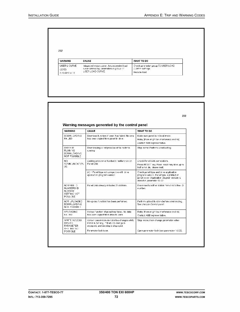
INSTALLATION GUIDE APPENDIX E: TRIP AND WARNING CODES
CONTACT: 1-877-TESCO-77 350/400 TON EXI 600HP WWW.TESCOCORP.COM
INTL: 713-359-7295 72 WWW.TESCOPARTS.COM

APPENDIX E: TRIP AND WARNING CODES INSTALLATION GUIDE
CONTACT: 1-877-TESCO-77 350/400 TON EXI 600HP WWW.TESCOCORP.COM
INTL: 713-359-7295 73 WWW.TESCOPARTS.COM

INSTALLATION GUIDE APPENDIX E: TRIP AND WARNING CODES
CONTACT: 1-877-TESCO-77 350/400 TON EXI 600HP WWW.TESCOCORP.COM
INTL: 713-359-7295 74 WWW.TESCOPARTS.COM

APPENDIX E: TRIP AND WARNING CODES INSTALLATION GUIDE
CONTACT: 1-877-TESCO-77 350/400 TON EXI 600HP WWW.TESCOCORP.COM
INTL: 713-359-7295 75 WWW.TESCOPARTS.COM

INSTALLATION GUIDE APPENDIX E: TRIP AND WARNING CODES
CONTACT: 1-877-TESCO-77 350/400 TON EXI 600HP WWW.TESCOCORP.COM
INTL: 713-359-7295 76 WWW.TESCOPARTS.COM

APPENDIX E: TRIP AND WARNING CODES INSTALLATION GUIDE
CONTACT: 1-877-TESCO-77 350/400 TON EXI 600HP WWW.TESCOCORP.COM
INTL: 713-359-7295 77 WWW.TESCOPARTS.COM

INSTALLATION GUIDE APPENDIX E: TRIP AND WARNING CODES
CONTACT: 1-877-TESCO-77 350/400 TON EXI 600HP WWW.TESCOCORP.COM
INTL: 713-359-7295 78 WWW.TESCOPARTS.COM
This page has been left blank intentionally.

APPENDIX F: TORQUE STANDARDS FOR HIGH STRENGTH FASTENERS INSTALLATION GUIDE
CONTACT: 1-877-TESCO-77 350/400 TON EXI 600HP WWW.TESCOCORP.COM
INTL: 713-359-7295 79 WWW.TESCOPARTS.COM
APPENDIX F: TORQUE STANDARDS FOR HIGH STRENGTH FASTENERS
The following information originated from the Standards document STD0015.
PURPOSE
This standard should be used as a guideline for all fasteners used in production where the torque values are not specified on the engineering documentation and drawings. All TESCO standards on fasteners should be adhered to, as non-conformance can lead to the following:
• low quality products• rework cost• warranty claims• late delivery• customer dissatisfaction• lower production
STANDARDS
1. All capscrews, bolts and nuts have to be Grade 8 or equivalent unless noted otherwise (U.N.O.).
2. Fasteners must be torqued in accordance with Table F-1, Table F-2, and Table F-3 U.N.O. Torques should be applied smoothly and with a calibrated wrench.
3. Multiple fastener arrays must be made up evenly using an appropriate torque sequence to minimize distortion. Fasteners shall be tightened using intermediate torque settings of 40% and 75% of values in the tables. All fasteners must be made up snug prior to starting the tightening sequence.
4. Fastener torques for bolting dissimilar materials must be based on the torque requirements for the lower strength material U.N.O.
5. Fasteners and holes should be free of burrs or damage. Damaged threads must be repaired using the appropriate tooling to ensure a free and smooth assembly.
6. When thread locking compound is used, holes and fasteners should be cleaned (free of oil or grease) and the compound should be applied in conformance with manufacturer’s recommendations.
7. Allowable bolt tension and torque based on bolt thread engagement must be in accordance with Table F-4 U.N.O.
8. Special fasteners must be installed and torqued in accordance with Table F-2.
9. When threadlock is used, fasteners must be torqued in accordance with Table F-1, Table F-2 and Table F-3, using the ‘Lubricated’ Torque data U.N.O.

INSTALLATION GUIDE APPENDIX F: TORQUE STANDARDS FOR HIGH STRENGTH FASTENERS
CONTACT: 1-877-TESCO-77 350/400 TON EXI 600HP WWW.TESCOCORP.COM
INTL: 713-359-7295 80 WWW.TESCOPARTS.COM
10. For torque values for B7 studs with 2H nuts, see Table F-3.
11. Lubricated fasteners must have oil or thread locking compound applied to the threads only.
12. Where metals with strongly varying electromotive properties are bolted together, such as steel and aluminum, thread locking compounds should be applied to limit the effects of galvanic corrosion.
13. A minimum of two full threads should project above any nut or locknut installed on a stud or as part of a bolted connection. Additional length is allowed to install safety pines or cotter pins to prevent fasteners from falling into overhead equipment.
TABLES
Table F-1: Standard torques
Material Aluminum (ft-lb) Mild Steel (ft-lb) High Strength Steel (ft-lb)
Size Dry Lubricated Dry Lubricated Dry Lubricated
1/4 in.-20 UNC 9 7 10 8 12 9
5/16 in.-18 UNC 16 12 19 15 25 19
3/8 in.-16 UNC 33 25 40 30 45 34
7/16 in.-14 UNC 47 36 57 43 70 53
1/2 in.-13 UNC 86 64 100 75 110 83
9/16 in.-12 UNC 118 88 141 106 160 120
5/8 in.-11 UNC 163 122 195 146 220 165
3/4 in.-10 UNC 278 209 333 250 400 300
7/8 in.-9 UNC 436 327 523 393 645 484
1 in.-8 UNC 667 500 800 600 970 728
1-1/8 in.-7 UNC 950 713 1142 856 1370 1028
1-1/4 in.-7 UNC 1317 988 1575 1181 1900 1425
1-1/2 in.-6 UNC 2283 1713 2742 2056 3200 2400
Recommended torques are based on bolt tensions of approximately 80% of the yield strength and a minimum of one bolt diameter class 2B thread engagement in the material, or bolt head bearing pressures, whichever is less.

APPENDIX F: TORQUE STANDARDS FOR HIGH STRENGTH FASTENERS INSTALLATION GUIDE
CONTACT: 1-877-TESCO-77 350/400 TON EXI 600HP WWW.TESCOCORP.COM
INTL: 713-359-7295 81 WWW.TESCOPARTS.COM
Table F-2: Special fastener torques
Fastener DescriptionMinimum
EngagementMild Steel (ft-lb) High Strength Steel (ft-lb)
Dry Lubricated Dry Lubricated
UNBRAKO 5/16 in.-18 UNRC 3/8 in. 27 20 35 26
UNBRAKO 1/2 in.-13 UNRC 1/2 in. 118 88 154 115
UNBRAKO 5/8 in.-11 UNRC 5/8 in. 217 162 283 212
Special fasteners shall be used only in critical locations or special applications. Thread engagement is based on the minimum class 2B tapped threads in mild steel capable of developing bolt tension 80% of bolt yield. When using hardened steel washers on mild steel, use torque values for high strength steel.
Table F-3: B7 Stud torques
Stud Size Dry (ft-lb) Lubricated (ft-lb)
1/2 in.-3 UNC 85 64
5/8 in.-11 UNC 175 131
3/4 in.-10 UNC 300 225
7/8 in.-9 UNC 450 338
1 in.-8 UNC 680 510
1-1/8 in.-7 UNC 880 660
1-1/4 in.-7 UNC 1260 945
1-3/8 in.-6 UNC 1700 1275
1-1/2 in.-8 UN 2300 1725
Recommended torques are based on bolt tensions of approximately 75% of stud yield strength.
Table F-4: Thread engagements
Material Aluminum Mild Steel High Strength Steel
Engagement* % of Full Torque % of Full Torque % of Full Torque
100% 100% 100% 100%
90% 100% 100% 100%
80% 100% 100% 100%
70% 100% 100% 100%
60% 90% 100% 100%
50% 70% 100% 100%
40% 60% 75% 100%
30% 45% 60% 75%
20% 30% 40% 55%
* Engagement as a % of the bolt diameterValues represent the percentage of torque from Table F-1. Engagement does not include chamfer or incomplete threads. Engagements of less than one bolt diameter in tapped holes shall not be used without the engineer’s approval.

INSTALLATION GUIDE APPENDIX F: TORQUE STANDARDS FOR HIGH STRENGTH FASTENERS
CONTACT: 1-877-TESCO-77 350/400 TON EXI 600HP WWW.TESCOCORP.COM
INTL: 713-359-7295 82 WWW.TESCOPARTS.COM
This page has been left blank intentionally.

INDEX INSTALLATION GUIDE
CONTACT: 1-877-TESCO-77 350TON EXI 600HP WWW.TESCOCORP.COM
INTL: 713-359-7295 83 WWW.TESCOPARTS.COM
INDEX
Numerics600VAC
applying power, 38
Aair considerations, 6air intakes, 37air starter, 37auxiliary hydraulic power unit
disconnecting, 50placement during rig up, 7
auxiliary pump, 40
Bbattery, 37blocks, 24
Ccable roller saddle
optimal placement, 9placement factors, 10placement procedure, 10
circuit breakers, 37coolant levels, 37counter balance system
installation, 30
Ddamage
pre-installation inspection, 6danger
electrical warnings, 34drawworks interlock and override
installation, 29driller’s panel
installation, 28drive parameters
connect reverse, 43drill forward torque, 43modifying, 42set connect forward, 43set drill reverse speed and torque, 43
Eelectrical
warnings, 34emergency shut down (E.S.D.), 36
equipmentinspecting, 6inspecting for damage, 6placement, 7placement during rig up, 7placement procedure, 8
equipment placementauxiliary hydraulic power unit, 7cable roller saddle, 9power module, 7service loop reel, 9
ESD testtop drive, 38
exhaust, 37
Ffinal start up, 41fuel considerations, 5
Ggenerator
controls, 38starting, 37
Hhigh strength fasteners, torque standards, 79hydraulic system
checking, 40
Iinspecting equipment
pre-installation, 6inspection
general notes, 33installation
pre-installation measurement, 3rig measurement, 3
Mmain breakers, 37main panel control system, 36measurement
rig, 3mud pump interlock, 30
Ooptimal placement

INSTALLATION GUIDE INDEX
CONTACT: 1-877-TESCO-77 350TON EXI 600HP WWW.TESCOCORP.COM
INTL: 713-359-7295 84 WWW.TESCOPARTS.COM
auxiliary hydraulic power unit, 7power module, 7
Pphase rotation
checking, 39power
checklist, 4connection requirements, 3supplying to equipment, 38
power moduledisconnecting, 50placement during rig up, 7placement procedure, 8
pre-installationinspection, 6main power connection requirements, 3main power requirements checklist, 4measurement, 3
Rradiator, 37rig out
disconnect auxiliary hydraulic power unit, 50disconnect power module, 50remove the service loop, 47remove the top drive, 45remove the torque arrest system, 46
rig upequipment placement, 7install safety air interlocks, 29install the counter-balance system, 31install the driller’s panel, 28install the service loop, 11install the top drive, 23install the torque arrest system, 16
Ssafety air interlocks
installation, 29saver sub, 36service loop
installation option 1, 11installation option 2, 13removing, 47
service loop reeloptimal placement, 9
speedset connect forward, 43set connect reverse, 43set drill reverse, 43
start upfinal phase, 41
support systemsstart up, 37
Ttop drive
adjusting the extend arm, 27installation, 23preliminary checks and ESD test, 38starting, 38
torqueset connect forward, 43set connect reverse, 43set drill forward, 43set drill reverse, 43
torque arrest systembefore installing, 16components, 17configuration sample calculation, 19determine the configuration, 17installation, 16removing, 45, 46torque track, 19
torque bushing, 24torque track
mounting, 19transformer power
applying, 38
Wwarnings
before start up, 34condensation, 36electrical, 34other, 36

INSTALLATION GUIDE
CONTACT: 1-877-TESCO-77 350/400 TON EXI 600HP WWW.TESCOCORP.COM
INTL: 713-359-7295 85 WWW.TESCOPARTS.COM
ENGINEERING SIGN-OFF
This sign-off sheet indicates that this document has been approved for release by the Engineering Department at TESCO.
Document Complete By Signature Date Signed
Document Reviewed/Approved Date Signed
chane
Typewritten Text
Edward ChanSept. 28, 2009
madejskm
Typewritten Text
Oct. 22, 2009

INSTALLATION GUIDE
CONTACT: 1-877-TESCO-77 350/400 TON EXI 600HP WWW.TESCOCORP.COM
INTL: 713-359-7295 86 WWW.TESCOPARTS.COM
This page has been left blank intentionally.

DOCUMENT NAME: 880078 REV 2
Operations Guide
EXI Top Drive System
350/400 TON EXI 600HP


COPYRIGHT AND DISCLAIMER OPERATIONS GUIDE
CONTACT: 1-877-TESCO-77 350/400 TON EXI 600HP WWW.TESCOCORP.COM
INTL: 713-359-7295 I WWW.TESCOPARTS.COM
Tesco Corporation (“TESCO”) has made every effort to ensure that this document contains accurate and current information for the TESCO top drive, however, the document is intended to be used in conjunction with a complete training program and on-site supervision and TESCO does not warrant or guarantee that the information contained herein is either complete or accurate in every respect, and the reader hereby protects, indemnifies and holds harmless Tesco Corporation together with its directors, officers, employees and agents from and against all liability for personal injury, death or property damage to any person arising directly or indirectly from the use by the reader of the information contained in the document.
This equipment was filled at the factory with TESCO ULTREX™ brand fluids and greases. To ensure maximum performance and to avoid cross-contamination, we strongly recommend the continued usage of TESCO ULTREX™ lubricants, unless otherwise specified.
TESCO ULTREX™ is a trademark and TESCO® is a registered trademark of Tesco Corporation.
Tesco Corporation © 2009
Contact Information
Corporate Head Office3993 W. Sam Houston Parkway No., Suite 100
Houston, Texas, 77043USA
www.tescocorp.comwww.tescoparts.com
Telephone: (713) 359-7000Fax: (713) 359-7001
After Market Sales and Service ContactToll Free North America: 1-877-TESCO-77
International: 713-359-7295

REVISION INFORMATION OPERATIONS GUIDE
CONTACT: 1-877-TESCO-77 350/400 TON EXI 600HP WWW.TESCOCORP.COM
INTL: 713-359-7295 II WWW.TESCOPARTS.COM
Revision Information
Version Date Description of Changes
Rev 0 August 2007 Initial release
Rev 1 October 2008 Upgrade 350 EXI 600 to 350/400 EXI 600
Rev 2 September 2009 Added TESCO ULTREX™ recommendations and updated the footer to contain contact information.

TABLE OF CONTENTS OPERATIONS GUIDE
CONTACT: 1-877-TESCO-77 350/400 TON EXI 600HP WWW.TESCOCORP.COM
INTL: 713-359-7295 III WWW.TESCOPARTS.COM
TABLE OF CONTENTS
LIST OF FIGURES . . . . . . . . . . . . . . . . . . . . . . . . . . . . . . . . . . . . . . . . . . . . . . . . . . . . VII
SAFETY INSTRUCTIONS . . . . . . . . . . . . . . . . . . . . . . . . . . . . . . . . . . . . . . . . . . . . . . . . IX
CHAPTER 1: ABOUT THIS DOCUMENT . . . . . . . . . . . . . . . . . . . . . . . . . . . . . . . . . . . . . . 1
Warnings and Notices. . . . . . . . . . . . . . . . . . . . . . . . . . . . . . . . . . . . . . . . . . . . . . . . . . . . . . . . . . . . . . 2
CHAPTER 2: DRIVE SYSTEM . . . . . . . . . . . . . . . . . . . . . . . . . . . . . . . . . . . . . . . . . . . . . 3
System Description. . . . . . . . . . . . . . . . . . . . . . . . . . . . . . . . . . . . . . . . . . . . . . . . . . . . . . . . . . . . . . . . 3
Drive Control Panel . . . . . . . . . . . . . . . . . . . . . . . . . . . . . . . . . . . . . . . . . . . . . . . . . . . . . . . . . . . . . . . . 3
Monitoring the Drive . . . . . . . . . . . . . . . . . . . . . . . . . . . . . . . . . . . . . . . . . . . . . . . . . . . . . . . . . . . . . . . 9
CHAPTER 3: DRILLER’S PANEL . . . . . . . . . . . . . . . . . . . . . . . . . . . . . . . . . . . . . . . . . . 11
General Description . . . . . . . . . . . . . . . . . . . . . . . . . . . . . . . . . . . . . . . . . . . . . . . . . . . . . . . . . . . . . . 11
Controls, Indicators, and Warning Lights. . . . . . . . . . . . . . . . . . . . . . . . . . . . . . . . . . . . . . . . . . . . . 13
Warning Lights . . . . . . . . . . . . . . . . . . . . . . . . . . . . . . . . . . . . . . . . . . . . . . . . . . . . . . . . . . . . . . . . 13
Controls and Indicators for Robotic Functions . . . . . . . . . . . . . . . . . . . . . . . . . . . . . . . . . . . . . . . . 13
Drive Controls and Indicators . . . . . . . . . . . . . . . . . . . . . . . . . . . . . . . . . . . . . . . . . . . . . . . . . . . . . 14
Controls for Quill/Rotation Functions . . . . . . . . . . . . . . . . . . . . . . . . . . . . . . . . . . . . . . . . . . . . . . . 15
Meters. . . . . . . . . . . . . . . . . . . . . . . . . . . . . . . . . . . . . . . . . . . . . . . . . . . . . . . . . . . . . . . . . . . . . . . 15
Robotic and E.S.D. Function Descriptions . . . . . . . . . . . . . . . . . . . . . . . . . . . . . . . . . . . . . . . . . . . . 15
ELEVATOR Function . . . . . . . . . . . . . . . . . . . . . . . . . . . . . . . . . . . . . . . . . . . . . . . . . . . . . . . . . . . 16
TILT Function . . . . . . . . . . . . . . . . . . . . . . . . . . . . . . . . . . . . . . . . . . . . . . . . . . . . . . . . . . . . . . . . . 16
EXTEND Function . . . . . . . . . . . . . . . . . . . . . . . . . . . . . . . . . . . . . . . . . . . . . . . . . . . . . . . . . . . . . 16
VALVE Function . . . . . . . . . . . . . . . . . . . . . . . . . . . . . . . . . . . . . . . . . . . . . . . . . . . . . . . . . . . . . . . 17
GRABBER Function . . . . . . . . . . . . . . . . . . . . . . . . . . . . . . . . . . . . . . . . . . . . . . . . . . . . . . . . . . . . 17
PIPE HANDLER Function . . . . . . . . . . . . . . . . . . . . . . . . . . . . . . . . . . . . . . . . . . . . . . . . . . . . . . . 18
Emergency Shut Down (E.S.D.) . . . . . . . . . . . . . . . . . . . . . . . . . . . . . . . . . . . . . . . . . . . . . . . . . . . 18
E.S.D. on the Driller's Panel. . . . . . . . . . . . . . . . . . . . . . . . . . . . . . . . . . . . . . . . . . . . . . . . . . . . . . . . . . . . . . . . . . . . . . . . 18
E.S.D. on the Main Panel Control System . . . . . . . . . . . . . . . . . . . . . . . . . . . . . . . . . . . . . . . . . . . . . . . . . . . . . . . . . . . . . 18
Reset E.S.D . . . . . . . . . . . . . . . . . . . . . . . . . . . . . . . . . . . . . . . . . . . . . . . . . . . . . . . . . . . . . . . . . . . . . . . . . . . . . . . . . . . . 18
Controls for Torque and Speed . . . . . . . . . . . . . . . . . . . . . . . . . . . . . . . . . . . . . . . . . . . . . . . . . . . . . 19
DRILL Forward . . . . . . . . . . . . . . . . . . . . . . . . . . . . . . . . . . . . . . . . . . . . . . . . . . . . . . . . . . . . . . . . 19
Torque . . . . . . . . . . . . . . . . . . . . . . . . . . . . . . . . . . . . . . . . . . . . . . . . . . . . . . . . . . . . . . . . . . . . . . . . . . . . . . . . . . . . . . . . 19
Speed. . . . . . . . . . . . . . . . . . . . . . . . . . . . . . . . . . . . . . . . . . . . . . . . . . . . . . . . . . . . . . . . . . . . . . . . . . . . . . . . . . . . . . . . . 19
DRILL Reverse . . . . . . . . . . . . . . . . . . . . . . . . . . . . . . . . . . . . . . . . . . . . . . . . . . . . . . . . . . . . . . . . 19
Torque . . . . . . . . . . . . . . . . . . . . . . . . . . . . . . . . . . . . . . . . . . . . . . . . . . . . . . . . . . . . . . . . . . . . . . . . . . . . . . . . . . . . . . . . 19
Speed. . . . . . . . . . . . . . . . . . . . . . . . . . . . . . . . . . . . . . . . . . . . . . . . . . . . . . . . . . . . . . . . . . . . . . . . . . . . . . . . . . . . . . . . . 20
CONNECT Forward . . . . . . . . . . . . . . . . . . . . . . . . . . . . . . . . . . . . . . . . . . . . . . . . . . . . . . . . . . . . 20
Torque . . . . . . . . . . . . . . . . . . . . . . . . . . . . . . . . . . . . . . . . . . . . . . . . . . . . . . . . . . . . . . . . . . . . . . . . . . . . . . . . . . . . . . . . 20
Speed. . . . . . . . . . . . . . . . . . . . . . . . . . . . . . . . . . . . . . . . . . . . . . . . . . . . . . . . . . . . . . . . . . . . . . . . . . . . . . . . . . . . . . . . . 20

OPERATIONS GUIDE TABLE OF CONTENTS
CONTACT: 1-877-TESCO-77 350/400 TON EXI 600HP WWW.TESCOCORP.COM
INTL: 713-359-7295 IV WWW.TESCOPARTS.COM
CONNECT Reverse . . . . . . . . . . . . . . . . . . . . . . . . . . . . . . . . . . . . . . . . . . . . . . . . . . . . . . . . . . . .20
Torque . . . . . . . . . . . . . . . . . . . . . . . . . . . . . . . . . . . . . . . . . . . . . . . . . . . . . . . . . . . . . . . . . . . . . . . . . . . . . . . . . . . . . . . . 20
Speed . . . . . . . . . . . . . . . . . . . . . . . . . . . . . . . . . . . . . . . . . . . . . . . . . . . . . . . . . . . . . . . . . . . . . . . . . . . . . . . . . . . . . . . . . 20
BREAKOUT Button . . . . . . . . . . . . . . . . . . . . . . . . . . . . . . . . . . . . . . . . . . . . . . . . . . . . . . . . . . . . .20
Dual Function Remote Brake Handle Control . . . . . . . . . . . . . . . . . . . . . . . . . . . . . . . . . . . . . . . . .21
ELEVATOR–CLOSE . . . . . . . . . . . . . . . . . . . . . . . . . . . . . . . . . . . . . . . . . . . . . . . . . . . . . . . . . . . . . . . . . . . . . . . . . . . . . 21
GRABBER–Drawworks Interlock Override . . . . . . . . . . . . . . . . . . . . . . . . . . . . . . . . . . . . . . . . . . . . . . . . . . . . . . . . . . . . . 21
How to Calibrate the Meters on the Driller’s Panel . . . . . . . . . . . . . . . . . . . . . . . . . . . . . . . . . . . . . .21
Setting the Decimal Point of the LMD-120A Meters . . . . . . . . . . . . . . . . . . . . . . . . . . . . . . . . . . . .22
Set Driller’s Panel Meters . . . . . . . . . . . . . . . . . . . . . . . . . . . . . . . . . . . . . . . . . . . . . . . . . . . . . . . .23
CHAPTER 4: TORQUE AND SPEED LIMITS . . . . . . . . . . . . . . . . . . . . . . . . . . . . . . . . . . .25
Overview . . . . . . . . . . . . . . . . . . . . . . . . . . . . . . . . . . . . . . . . . . . . . . . . . . . . . . . . . . . . . . . . . . . . . . . .25
Drive Parameters . . . . . . . . . . . . . . . . . . . . . . . . . . . . . . . . . . . . . . . . . . . . . . . . . . . . . . . . . . . . . . . . .26
Overview . . . . . . . . . . . . . . . . . . . . . . . . . . . . . . . . . . . . . . . . . . . . . . . . . . . . . . . . . . . . . . . . . . . . .26
How to Set or Change Drive Parameters . . . . . . . . . . . . . . . . . . . . . . . . . . . . . . . . . . . . . . . . . . . .26
Setting Torque Limits . . . . . . . . . . . . . . . . . . . . . . . . . . . . . . . . . . . . . . . . . . . . . . . . . . . . . . . . . . . . .28
Breakout . . . . . . . . . . . . . . . . . . . . . . . . . . . . . . . . . . . . . . . . . . . . . . . . . . . . . . . . . . . . . . . . . . . . .28
Connect Forward. . . . . . . . . . . . . . . . . . . . . . . . . . . . . . . . . . . . . . . . . . . . . . . . . . . . . . . . . . . . . . .29
Connect Reverse. . . . . . . . . . . . . . . . . . . . . . . . . . . . . . . . . . . . . . . . . . . . . . . . . . . . . . . . . . . . . . .29
Drill Forward . . . . . . . . . . . . . . . . . . . . . . . . . . . . . . . . . . . . . . . . . . . . . . . . . . . . . . . . . . . . . . . . . .30
Drill Reverse . . . . . . . . . . . . . . . . . . . . . . . . . . . . . . . . . . . . . . . . . . . . . . . . . . . . . . . . . . . . . . . . . .30
Pipe Handler Settings . . . . . . . . . . . . . . . . . . . . . . . . . . . . . . . . . . . . . . . . . . . . . . . . . . . . . . . . . . . . .30
Pipe Handler Speed . . . . . . . . . . . . . . . . . . . . . . . . . . . . . . . . . . . . . . . . . . . . . . . . . . . . . . . . . . . .30
CHAPTER 5: OTHER PRE-OPERATIONAL PROCEDURES . . . . . . . . . . . . . . . . . . . . . . . . .31
Install the Saver Sub and Die Lock Clamp . . . . . . . . . . . . . . . . . . . . . . . . . . . . . . . . . . . . . . . . . . . .31
Orienting the Pipe Handler . . . . . . . . . . . . . . . . . . . . . . . . . . . . . . . . . . . . . . . . . . . . . . . . . . . . . . . . .32
Setting the Grabber Height . . . . . . . . . . . . . . . . . . . . . . . . . . . . . . . . . . . . . . . . . . . . . . . . . . . . . . . . .32
How to Adjust the Grabber-Lift Height Limit . . . . . . . . . . . . . . . . . . . . . . . . . . . . . . . . . . . . . . . . . . .33
Setting the Grabber Closing Pressure . . . . . . . . . . . . . . . . . . . . . . . . . . . . . . . . . . . . . . . . . . . . . . . .35
CHAPTER 6: MAKING/BREAKING CONNECTIONS . . . . . . . . . . . . . . . . . . . . . . . . . . . . . .37
Warnings. . . . . . . . . . . . . . . . . . . . . . . . . . . . . . . . . . . . . . . . . . . . . . . . . . . . . . . . . . . . . . . . . . . . . . . .37
Mudsaver Valve. . . . . . . . . . . . . . . . . . . . . . . . . . . . . . . . . . . . . . . . . . . . . . . . . . . . . . . . . . . . . . . .37
Pipe Slips . . . . . . . . . . . . . . . . . . . . . . . . . . . . . . . . . . . . . . . . . . . . . . . . . . . . . . . . . . . . . . . . . . . .37
How to Make Connections–General . . . . . . . . . . . . . . . . . . . . . . . . . . . . . . . . . . . . . . . . . . . . . . . . .38
How to Use the Mousehole to Connect Drill Pipe to the Top Drive. . . . . . . . . . . . . . . . . . . . . . . . .39
Pipe Handler Orientation–Grabber to V-door . . . . . . . . . . . . . . . . . . . . . . . . . . . . . . . . . . . . . . . . . . . . . . . . . . . . . . . . . . . 39
Pipe Handler Orientation–Grabber to Drawworks . . . . . . . . . . . . . . . . . . . . . . . . . . . . . . . . . . . . . . . . . . . . . . . . . . . . . . . 41
How to Fully Torque a Connection . . . . . . . . . . . . . . . . . . . . . . . . . . . . . . . . . . . . . . . . . . . . . . . . .42
How to Connect a Single Length of Drill Pipe to the Drill String . . . . . . . . . . . . . . . . . . . . . . . . . . .42

TABLE OF CONTENTS OPERATIONS GUIDE
CONTACT: 1-877-TESCO-77 350/400 TON EXI 600HP WWW.TESCOCORP.COM
INTL: 713-359-7295 V WWW.TESCOPARTS.COM
How to Break the Top Drive/Drill Pipe Connection . . . . . . . . . . . . . . . . . . . . . . . . . . . . . . . . . . . . . 44
How to Use the Pipe Handler to Make Up Pipe Stands . . . . . . . . . . . . . . . . . . . . . . . . . . . . . . . . . . 45
How to Make Up Stands in the Rotary Table . . . . . . . . . . . . . . . . . . . . . . . . . . . . . . . . . . . . . . . . 45
How to Make Up Pipe Stands Without a Conductor Pipe. . . . . . . . . . . . . . . . . . . . . . . . . . . . . . . . 47
How to Make Up Pipe Stands in the Mousehole . . . . . . . . . . . . . . . . . . . . . . . . . . . . . . . . . . . . . . 48
How to Make Up BHA (Collars and Tools) . . . . . . . . . . . . . . . . . . . . . . . . . . . . . . . . . . . . . . . . . . . . 50
How to Connect Collars Above the Rotary Table . . . . . . . . . . . . . . . . . . . . . . . . . . . . . . . . . . . . . . 52
CHAPTER 7: DRILLING OPERATIONS . . . . . . . . . . . . . . . . . . . . . . . . . . . . . . . . . . . . . . 55
Well Control . . . . . . . . . . . . . . . . . . . . . . . . . . . . . . . . . . . . . . . . . . . . . . . . . . . . . . . . . . . . . . . . . . . . . 55
Surface Hole Drilling Operations . . . . . . . . . . . . . . . . . . . . . . . . . . . . . . . . . . . . . . . . . . . . . . . . . . . . 55
How to Drill a Surface Hole . . . . . . . . . . . . . . . . . . . . . . . . . . . . . . . . . . . . . . . . . . . . . . . . . . . . . . 55
About Connections and Surface Hole Operations . . . . . . . . . . . . . . . . . . . . . . . . . . . . . . . . . . . . . 56
About Tripping and Surface Hole Operations. . . . . . . . . . . . . . . . . . . . . . . . . . . . . . . . . . . . . . . . . 56
About Reaming and Surface Hole Operations . . . . . . . . . . . . . . . . . . . . . . . . . . . . . . . . . . . . . . . . 57
How to Drill Ahead with Single Lengths of Pipe . . . . . . . . . . . . . . . . . . . . . . . . . . . . . . . . . . . . . . . 57
How to Drill Ahead with Pipe Stands. . . . . . . . . . . . . . . . . . . . . . . . . . . . . . . . . . . . . . . . . . . . . . . . . 60
Slide Drilling Operations . . . . . . . . . . . . . . . . . . . . . . . . . . . . . . . . . . . . . . . . . . . . . . . . . . . . . . . . . . 63
Introduction. . . . . . . . . . . . . . . . . . . . . . . . . . . . . . . . . . . . . . . . . . . . . . . . . . . . . . . . . . . . . . . . . . . 63
Mud Motors in Slide Drilling Operations . . . . . . . . . . . . . . . . . . . . . . . . . . . . . . . . . . . . . . . . . . . . . 63
How to Adjust the Tool Face Orientation . . . . . . . . . . . . . . . . . . . . . . . . . . . . . . . . . . . . . . . . . . . . 64
How to Make and Break Connections During Slide Drilling Operations . . . . . . . . . . . . . . . . . . . . . 65
How to Maintain the Tool Face Orientation During Slide Drilling Operations . . . . . . . . . . . . . . . . . 67
How to Record the Drill String Torque . . . . . . . . . . . . . . . . . . . . . . . . . . . . . . . . . . . . . . . . . . . . . . 67
Combination Drilling Operations . . . . . . . . . . . . . . . . . . . . . . . . . . . . . . . . . . . . . . . . . . . . . . . . . . . . 68
Summary . . . . . . . . . . . . . . . . . . . . . . . . . . . . . . . . . . . . . . . . . . . . . . . . . . . . . . . . . . . . . . . . . . . . 68
Explanation. . . . . . . . . . . . . . . . . . . . . . . . . . . . . . . . . . . . . . . . . . . . . . . . . . . . . . . . . . . . . . . . . . . 68
CHAPTER 8: TRIPPING OPERATIONS . . . . . . . . . . . . . . . . . . . . . . . . . . . . . . . . . . . . . . 69
Well Control During Tripping Operations . . . . . . . . . . . . . . . . . . . . . . . . . . . . . . . . . . . . . . . . . . . . . 69
How to Remove the Mudsaver Valve Actuator During Well Control Tripping. . . . . . . . . . . . . . . . . 70
Trip Out Operations . . . . . . . . . . . . . . . . . . . . . . . . . . . . . . . . . . . . . . . . . . . . . . . . . . . . . . . . . . . . . . 72
How to Trip Out Drill Pipe . . . . . . . . . . . . . . . . . . . . . . . . . . . . . . . . . . . . . . . . . . . . . . . . . . . . . . . . 73
Standard Racking Procedure . . . . . . . . . . . . . . . . . . . . . . . . . . . . . . . . . . . . . . . . . . . . . . . . . . . . . 75
How to Trip Out BHA (Collars and Tools). . . . . . . . . . . . . . . . . . . . . . . . . . . . . . . . . . . . . . . . . . . . 75
Trip In Operations . . . . . . . . . . . . . . . . . . . . . . . . . . . . . . . . . . . . . . . . . . . . . . . . . . . . . . . . . . . . . . . . 78
How to Trip in Tools and Collars . . . . . . . . . . . . . . . . . . . . . . . . . . . . . . . . . . . . . . . . . . . . . . . . . . 78
How to Trip In Drill Pipe . . . . . . . . . . . . . . . . . . . . . . . . . . . . . . . . . . . . . . . . . . . . . . . . . . . . . . . . . 80
Reaming Operations . . . . . . . . . . . . . . . . . . . . . . . . . . . . . . . . . . . . . . . . . . . . . . . . . . . . . . . . . . . . . . 81
How to Use the Top Drive to Ream During Trip Out Operations . . . . . . . . . . . . . . . . . . . . . . . . . . 81
How to Use the Top Drive to Ream to Bottom During Trip In Operations . . . . . . . . . . . . . . . . . . . 82

OPERATIONS GUIDE TABLE OF CONTENTS
CONTACT: 1-877-TESCO-77 350/400 TON EXI 600HP WWW.TESCOCORP.COM
INTL: 713-359-7295 VI WWW.TESCOPARTS.COM
CHAPTER 9: STUCK PIPE . . . . . . . . . . . . . . . . . . . . . . . . . . . . . . . . . . . . . . . . . . . . . . .85
How to Use the Top Drive to Free Stuck Pipe . . . . . . . . . . . . . . . . . . . . . . . . . . . . . . . . . . . . . . . . . .85
How to Use the Top Drive for Jarring Operations. . . . . . . . . . . . . . . . . . . . . . . . . . . . . . . . . . . . . . .86
Controlled Drill String Back Off Operations . . . . . . . . . . . . . . . . . . . . . . . . . . . . . . . . . . . . . . . . . . .87
Uncontrolled Parting of the Drill String . . . . . . . . . . . . . . . . . . . . . . . . . . . . . . . . . . . . . . . . . . . . . . .88
CHAPTER 10: RUN AND PULL CASING . . . . . . . . . . . . . . . . . . . . . . . . . . . . . . . . . . . . .89
Prepare the Top Drive to Run Casing . . . . . . . . . . . . . . . . . . . . . . . . . . . . . . . . . . . . . . . . . . . . . . . .90
How to Run Casing . . . . . . . . . . . . . . . . . . . . . . . . . . . . . . . . . . . . . . . . . . . . . . . . . . . . . . . . . . . . . . .91
How to Pull Casing. . . . . . . . . . . . . . . . . . . . . . . . . . . . . . . . . . . . . . . . . . . . . . . . . . . . . . . . . . . . . . . .93
CHAPTER 11: TOP DRIVE CONSIDERATIONS . . . . . . . . . . . . . . . . . . . . . . . . . . . . . . . . .95
Slip and Cut Operations . . . . . . . . . . . . . . . . . . . . . . . . . . . . . . . . . . . . . . . . . . . . . . . . . . . . . . . . . . .95
Cementing Operations. . . . . . . . . . . . . . . . . . . . . . . . . . . . . . . . . . . . . . . . . . . . . . . . . . . . . . . . . . . . .96
Slickline Survey and Wireline Logging Operations . . . . . . . . . . . . . . . . . . . . . . . . . . . . . . . . . . . . .96
Heavy Loads at the V-Door . . . . . . . . . . . . . . . . . . . . . . . . . . . . . . . . . . . . . . . . . . . . . . . . . . . . . . . . .98
APPENDIX A: POST JARRING CHECKLIST . . . . . . . . . . . . . . . . . . . . . . . . . . . . . . . . . . .99
INDEX. . . . . . . . . . . . . . . . . . . . . . . . . . . . . . . . . . . . . . . . . . . . . . . . . . . . . . . . . . . . .101

LIST OF FIGURES OPERATIONS GUIDE
CONTACT: 1-877-TESCO-77 350/400 TON EXI 600HP WWW.TESCOCORP.COM
INTL: 713-359-7295 VII WWW.TESCOPARTS.COM
LIST OF FIGURES
Figure 2-1: ACS800 . . . . . . . . . . . . . . . . . . . . . . . . . . . . . . . . . . . . . . . . . . . . . . . . . . . . . . . . . . . . . . . . 4Figure 2-2: Panel operation mode keys and displays . . . . . . . . . . . . . . . . . . . . . . . . . . . . . . . . . . . . . . 5Figure 2-3: Actual signal display mode . . . . . . . . . . . . . . . . . . . . . . . . . . . . . . . . . . . . . . . . . . . . . . . . . 6Figure 2-4: Displaying full name of signals and viewing and resetting history . . . . . . . . . . . . . . . . . . . . 7Figure 2-5: Displaying and resetting an active fault . . . . . . . . . . . . . . . . . . . . . . . . . . . . . . . . . . . . . . . . 8Figure 2-6: Monitoring the drive - table 1 . . . . . . . . . . . . . . . . . . . . . . . . . . . . . . . . . . . . . . . . . . . . . . . . 9Figure 2-7: Monitoring the drive - table 2 . . . . . . . . . . . . . . . . . . . . . . . . . . . . . . . . . . . . . . . . . . . . . . . 10Figure 3-1: Driller’s panel . . . . . . . . . . . . . . . . . . . . . . . . . . . . . . . . . . . . . . . . . . . . . . . . . . . . . . . . . . . 12Figure 3-2: LMD-120A gauge rear view . . . . . . . . . . . . . . . . . . . . . . . . . . . . . . . . . . . . . . . . . . . . . . . . 22Figure 4-1: EXI 600 Torque Curve . . . . . . . . . . . . . . . . . . . . . . . . . . . . . . . . . . . . . . . . . . . . . . . . . . . . 25Figure 5-1: Rotary seal valve . . . . . . . . . . . . . . . . . . . . . . . . . . . . . . . . . . . . . . . . . . . . . . . . . . . . . . . . 34Figure 5-2: Grabber intensifier manifold. . . . . . . . . . . . . . . . . . . . . . . . . . . . . . . . . . . . . . . . . . . . . . . . 36Figure 6-1: Correct tong position to make a connection. . . . . . . . . . . . . . . . . . . . . . . . . . . . . . . . . . . . 38Figure 6-2: Correct position for elevator links and elevator . . . . . . . . . . . . . . . . . . . . . . . . . . . . . . . . . 40Figure 6-3: Elevator links and elevator position with grabber to drawworks . . . . . . . . . . . . . . . . . . . . 41Figure 6-4: Connect a single length of pipe to the drill string . . . . . . . . . . . . . . . . . . . . . . . . . . . . . . . . 43Figure 6-5: Break the top drive/drill pipe connection . . . . . . . . . . . . . . . . . . . . . . . . . . . . . . . . . . . . . . 44Figure 6-6: Make up stands in the rotary table. . . . . . . . . . . . . . . . . . . . . . . . . . . . . . . . . . . . . . . . . . . 45Figure 6-7: Make up pipe stands in the mousehole . . . . . . . . . . . . . . . . . . . . . . . . . . . . . . . . . . . . . . . 48Figure 6-8: Connect collars . . . . . . . . . . . . . . . . . . . . . . . . . . . . . . . . . . . . . . . . . . . . . . . . . . . . . . . . . 50Figure 7-1: Drill ahead with single lengths of pipe . . . . . . . . . . . . . . . . . . . . . . . . . . . . . . . . . . . . . . . . 57Figure 7-2: Drill ahead with pipe stands . . . . . . . . . . . . . . . . . . . . . . . . . . . . . . . . . . . . . . . . . . . . . . . . 60Figure 8-1: Remove the mudsaver valve actuator for well control . . . . . . . . . . . . . . . . . . . . . . . . . . . . 71Figure 8-2: Remove the actuator from the mudsaver valve . . . . . . . . . . . . . . . . . . . . . . . . . . . . . . . . . 72Figure 8-3: Trip out drill pipe . . . . . . . . . . . . . . . . . . . . . . . . . . . . . . . . . . . . . . . . . . . . . . . . . . . . . . . . 73Figure 8-4: Trip out collars . . . . . . . . . . . . . . . . . . . . . . . . . . . . . . . . . . . . . . . . . . . . . . . . . . . . . . . . . . 76Figure 8-5: Trip in tools and collars . . . . . . . . . . . . . . . . . . . . . . . . . . . . . . . . . . . . . . . . . . . . . . . . . . . 78Figure 9-1: Neutral weight at the connection . . . . . . . . . . . . . . . . . . . . . . . . . . . . . . . . . . . . . . . . . . . . 88Figure 10-1: Pick up casing . . . . . . . . . . . . . . . . . . . . . . . . . . . . . . . . . . . . . . . . . . . . . . . . . . . . . . . . . 89Figure 10-2: Run casing . . . . . . . . . . . . . . . . . . . . . . . . . . . . . . . . . . . . . . . . . . . . . . . . . . . . . . . . . . . . 91Figure 10-3: Reduce the stress on the torque track . . . . . . . . . . . . . . . . . . . . . . . . . . . . . . . . . . . . . . . 92Figure 11-1: Block sling . . . . . . . . . . . . . . . . . . . . . . . . . . . . . . . . . . . . . . . . . . . . . . . . . . . . . . . . . . . . 95

OPERATIONS GUIDE LIST OF FIGURES
CONTACT: 1-877-TESCO-77 350/400 TON EXI 600HP WWW.TESCOCORP.COM
INTL: 713-359-7295 VIII WWW.TESCOPARTS.COM
This page has been left blank intentionally.

SAFETY INSTRUCTIONS OPERATIONS GUIDE
CONTACT: 1-877-TESCO-77 350/400 TON EXI 600HP WWW.TESCOCORP.COM
INTL: 713-359-7295 IX WWW.TESCOPARTS.COM
SAFETY INSTRUCTIONS
Warning! Before operating and servicing this top drive system, always read and follow all safety instructions such as the warnings and cautions mentioned below and throughout the manual.
Top Drive System users risk injury to themselves and to others if the top drive is used improperly and/or safety precautions are not followed. TESCO advises personnel who work with or near the equipment to always wear proper personal protective equipment (PPE). Proper PPE consists of, but is not limited to, the following:
• hearing protection (ear defenders)• hard hat• safety glasses• steel toe shoes• fall protection when working above 6.5 ft (2 m), or the minimum height
requirement as directed by local jurisdiction.
Caution: This equipment is designed and certified for use in a hazardous environment. When maintenance requires replacement of parts, only identical parts can be used. Using alternate, non-iden-tical parts as a substitution may void compliance and certification.
Caution: Always perform the correct lock-out procedures as recommended by the Safety or Loss Prevention department before implementing maintenance.
Caution: Only authorized personnel can operate the top drive system.
Caution: This equipment can generate noise up to 90 decibels. Hearing protection suitable for this noise level must be worn when operating this equipment.
!
!
!
!
!

OPERATIONS GUIDE SAFETY INSTRUCTIONS
CONTACT: 1-877-TESCO-77 350/400 TON EXI 600HP WWW.TESCOCORP.COM
INTL: 713-359-7295 X WWW.TESCOPARTS.COM
Warning! Electrical voltages of different potentials are used throughout the TESCO top drive components (600 VAC, 208 VAC, 120 VAC, 840 VDC, 5-24 VDC). It is imperative that only qualified personnel install, maintain and/or troubleshoot the electrical systems. A severe hazard exists to personnel not accustomed to, or familiar with, electrical hazards and procedures.
Warning! There are high voltage capacitors installed in the ACS800 drive module. It is imperative that at least 5 minutes elapse, after power to the drive has been turned off, before any testing or repairs be undertaken at the module. The capacitors require time to ‘drain’ their stored electrical energy.
Warning! Accumulators used in the auxiliary hydraulic system are under the pressure of gas. Release this pressure before any maintenance is done on the auxiliary hydraulic system.
!
!
!

CHAPTER 1: ABOUT THIS DOCUMENT OPERATIONS GUIDE
CONTACT: 1-877-TESCO-77 350/400 TON EXI 600HP WWW.TESCOCORP.COM
INTL: 713-359-7295 1 WWW.TESCOPARTS.COM
CHAPTER 1: ABOUT THIS DOCUMENT
This Operations Guide contains information on how to use the 350/400 TON EXI 600HP top drive system. It includes information on:
• powering up the top drive• starting, stopping, and resetting the top drive• configuring torque and speed settings• using the driller’s panel• making and breaking connections (drill pipe, collars, etc.)• drilling• tripping pipe• freeing stuck pipe (including jarring)• running and pulling casing• using the top drive for special operations
Caution: This guide assumes the following: the top drive has been installed correctly; the power system is enabled; and all required safety checks have been performed. These procedures are explained in the Installation Guide for the unit.
Table 1-1: Where to find more information
For information on Refer to
system components System Description
• installing the top drive• rig up procedure• commissioning• pre-operational checklists• rig out procedure
Installation Guide
• load path inspections• maintenance/service schedules• component disassembly and reassembly• long term storage procedures
Maintenance Guide
TESCO manufactured parts and part numbers Parts List
troubleshooting Troubleshooting Guide (where available)
• electrical schematics• hydraulic schematics• cooling schematics• gearbox lubrication schematics
System schematics
available options and spares TESCO representative
!

OPERATIONS GUIDE CHAPTER 1: ABOUT THIS DOCUMENT
CONTACT: 1-877-TESCO-77 350/400 TON EXI 600HP WWW.TESCOCORP.COM
INTL: 713-359-7295 2 WWW.TESCOPARTS.COM
WARNINGS AND NOTICES
Warning! Electrical voltages of different potentials are used throughout the TESCO top drive components (600 VAC, 208 VAC, 120 VAC, 840 VDC, 5-24 VDC). It is imperative that only qualified personnel install, maintain and/or troubleshoot the electrical systems. A severe hazard exists to personnel not accustomed to, or familiar with, electrical hazards and procedures.
Warning! There are high voltage capacitors installed in the ACS800 drive module. It is imperative that at least 5 minutes elapse, after power to the drive has been turned off, before any testing or repairs be undertaken at the module. The capacitors require time to ‘drain’ their stored electrical energy.
!
!

CHAPTER 2: DRIVE SYSTEM OPERATIONS GUIDE
CONTACT: 1-877-TESCO-77 350/400 TON EXI 600HP WWW.TESCOCORP.COM
INTL: 713-359-7295 3 WWW.TESCOPARTS.COM
CHAPTER 2: DRIVE SYSTEM
SYSTEM DESCRIPTION
The 350/400 EXI 600 Top Drive features a 600 hp induction motor coupled with an ABBACS800 variable frequency drive. The system voltage is 600 VAC and can be supplied by a self-contained generator or directly from the rig’s AC bus.
The motor is rated for 600hp with 150% overload capability for 60 seconds. The maximumspeed of the motor is 2,340 rpm. The motor can produce a maximum torque of 2,700 ft-lb (3,661 N-m). RTDs are embedded in the motor’s stator windings to monitor the motor temperature during operation.
The ABB ACS800 variable frequency drive (VFD) is a modular unit comprised of four main sections: a main breaker and control cabinet, a diode supply unit, two inverter modules, and a dynamic braking unit. The main breaker is rated for 1,000A and features an undervoltage trip circuit, which is tied directly to the ESD control on the driller’s panel. The dynamic brake is connected to a grid resistor which is mounted on the rear outside wall of the power module.
The 350/400 EXI 600 uses a closed loop speed control scheme with variable torque limits. The top drive motor is driven by the ACS800 variable frequency drive which in turn is controlled by a GE Fanuc PLC via RS485 serial communication. The PLC issues START/STOP com-mands as well as speed reference and torque limit values to the VFD. The VFD then drives the motor accordingly. The PLC receives speed feedback from the motor encoder, as well as torque feedback from the VFD. It also controls the auxiliary robotics functions of the top drive.
DRIVE CONTROL PANEL
The Drive Control Panel CDP312R is a small keypad located on the front door of the main VFD breaker cabinet. It provides a visual user interface for setting and displaying drive parameters, monitoring drive status, and indicating warnings and faults.
Figure 2-1 through Figure 2-7 show the Drive Control Panel and describes the function of indicators and keys.
1. Only qualified TESCO personnel certified by ABB should attempt to change or modify drive parameters. Incorrect drive programming may result in equipment damage or injury to personnel. As a precaution, the drive parameters are password protected to prevent unauthorized access.

OPERATIONS GUIDE CHAPTER 2: DRIVE SYSTEM
CONTACT: 1-877-TESCO-77 350/400 TON EXI 600HP WWW.TESCOCORP.COM
INTL: 713-359-7295 4 WWW.TESCOPARTS.COM
The panel can be operated to perform the following actions:
• display actual motor signals such as speed, torque, frequency, etc.• reset the fault and warning messages• change between local and external drive control
Figure 2-1: ACS800

CHAPTER 2: DRIVE SYSTEM OPERATIONS GUIDE
CONTACT: 1-877-TESCO-77 350/400 TON EXI 600HP WWW.TESCOCORP.COM
INTL: 713-359-7295 5 WWW.TESCOPARTS.COM
Figure 2-2: Panel operation mode keys and displays

OPERATIONS GUIDE CHAPTER 2: DRIVE SYSTEM
CONTACT: 1-877-TESCO-77 350/400 TON EXI 600HP WWW.TESCOCORP.COM
INTL: 713-359-7295 6 WWW.TESCOPARTS.COM
Figure 2-3: Actual signal display mode

CHAPTER 2: DRIVE SYSTEM OPERATIONS GUIDE
CONTACT: 1-877-TESCO-77 350/400 TON EXI 600HP WWW.TESCOCORP.COM
INTL: 713-359-7295 7 WWW.TESCOPARTS.COM
Figure 2-4: Displaying full name of signals and viewing and resetting history

OPERATIONS GUIDE CHAPTER 2: DRIVE SYSTEM
CONTACT: 1-877-TESCO-77 350/400 TON EXI 600HP WWW.TESCOCORP.COM
INTL: 713-359-7295 8 WWW.TESCOPARTS.COM
Figure 2-5: Displaying and resetting an active fault
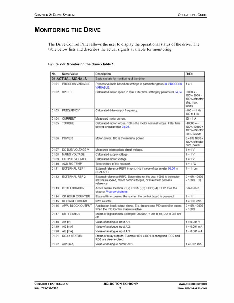
CHAPTER 2: DRIVE SYSTEM OPERATIONS GUIDE
CONTACT: 1-877-TESCO-77 350/400 TON EXI 600HP WWW.TESCOCORP.COM
INTL: 713-359-7295 9 WWW.TESCOPARTS.COM
MONITORING THE DRIVE
The Drive Control Panel allows the user to display the operational status of the drive. The table below lists and describes the actual signals available for monitoring.
Figure 2-6: Monitoring the drive - table 1
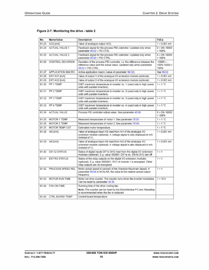
OPERATIONS GUIDE CHAPTER 2: DRIVE SYSTEM
CONTACT: 1-877-TESCO-77 350/400 TON EXI 600HP WWW.TESCOCORP.COM
INTL: 713-359-7295 10 WWW.TESCOPARTS.COM
Figure 2-7: Monitoring the drive - table 2

CHAPTER 3: DRILLER’S PANEL OPERATIONS GUIDE
CONTACT: 1-877-TESCO-77 350/400 TON EXI 600HP WWW.TESCOCORP.COM
INTL: 713-359-7295 11 WWW.TESCOPARTS.COM
CHAPTER 3: DRILLER’S PANEL
GENERAL DESCRIPTION
The driller’s panel is a stainless steel enclosed panel that provides access to all required switches, indicators, mounts, gauges and connectors.
The driller’s panel provides the controls, instrumentation and indicators required for safe operation of the top drive. The panel mounts at the rig floor, within convenient reach of the driller.
The driller’s panel interfaces with the main panel control system.
Table 3-1: Features of the 350/400 TON EXI 600HP driller’s panel
Controls
• robotic functions• drive functions• Emergency Shut Down (E.S.D.)
Meters
• SET speed• DELIVERED speed• SET torque• DELIVERED torque
Indicators
• warnings• status

OPERATIONS GUIDE CHAPTER 3: DRILLER’S PANEL
CONTACT: 1-877-TESCO-77 350/400 TON EXI 600HP WWW.TESCOCORP.COM
INTL: 713-359-7295 12 WWW.TESCOPARTS.COM
Figure 3-1: Driller’s panel
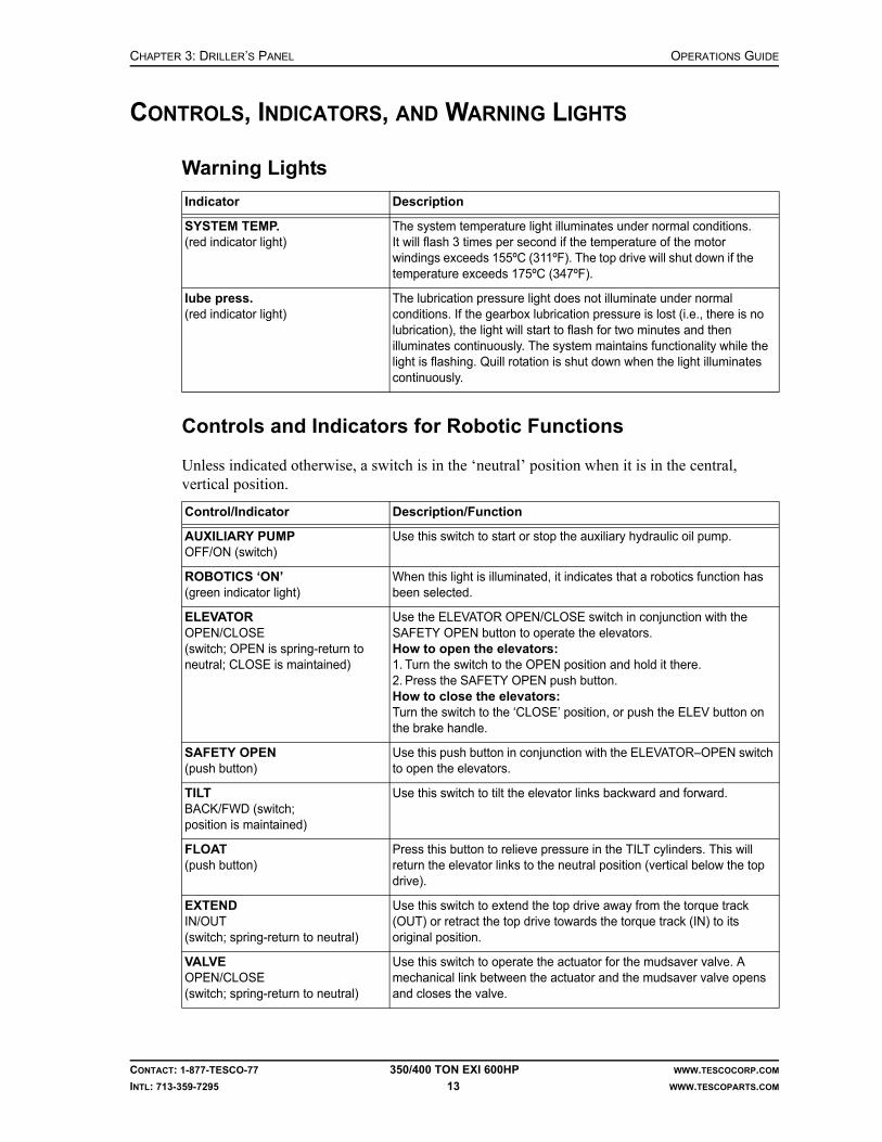
CHAPTER 3: DRILLER’S PANEL OPERATIONS GUIDE
CONTACT: 1-877-TESCO-77 350/400 TON EXI 600HP WWW.TESCOCORP.COM
INTL: 713-359-7295 13 WWW.TESCOPARTS.COM
CONTROLS, INDICATORS, AND WARNING LIGHTS
Warning Lights
Controls and Indicators for Robotic Functions
Unless indicated otherwise, a switch is in the ‘neutral’ position when it is in the central, vertical position.
Indicator Description
SYSTEM TEMP.(red indicator light)
The system temperature light illuminates under normal conditions. It will flash 3 times per second if the temperature of the motor windings exceeds 155ºC (311ºF). The top drive will shut down if the temperature exceeds 175ºC (347ºF).
lube press.(red indicator light)
The lubrication pressure light does not illuminate under normal conditions. If the gearbox lubrication pressure is lost (i.e., there is no lubrication), the light will start to flash for two minutes and then illuminates continuously. The system maintains functionality while the light is flashing. Quill rotation is shut down when the light illuminates continuously.
Control/Indicator Description/Function
AUXILIARY PUMPOFF/ON (switch)
Use this switch to start or stop the auxiliary hydraulic oil pump.
ROBOTICS ‘ON’(green indicator light)
When this light is illuminated, it indicates that a robotics function has been selected.
ELEVATOROPEN/CLOSE(switch; OPEN is spring-return to neutral; CLOSE is maintained)
Use the ELEVATOR OPEN/CLOSE switch in conjunction with the SAFETY OPEN button to operate the elevators.How to open the elevators:1. Turn the switch to the OPEN position and hold it there.2. Press the SAFETY OPEN push button.How to close the elevators:Turn the switch to the ‘CLOSE’ position, or push the ELEV button on the brake handle.
SAFETY OPEN(push button)
Use this push button in conjunction with the ELEVATOR–OPEN switch to open the elevators.
TILTBACK/FWD (switch; position is maintained)
Use this switch to tilt the elevator links backward and forward.
FLOAT(push button)
Press this button to relieve pressure in the TILT cylinders. This will return the elevator links to the neutral position (vertical below the top drive).
EXTENDIN/OUT(switch; spring-return to neutral)
Use this switch to extend the top drive away from the torque track (OUT) or retract the top drive towards the torque track (IN) to its original position.
VALVEOPEN/CLOSE(switch; spring-return to neutral)
Use this switch to operate the actuator for the mudsaver valve. A mechanical link between the actuator and the mudsaver valve opens and closes the valve.

OPERATIONS GUIDE CHAPTER 3: DRILLER’S PANEL
CONTACT: 1-877-TESCO-77 350/400 TON EXI 600HP WWW.TESCOCORP.COM
INTL: 713-359-7295 14 WWW.TESCOPARTS.COM
Drive Controls and Indicators
VALVE ‘CLOSED’(yellow indicator light)
When this light is illuminated, it indicates that ‘VALVE–CLOSE’ has been selected.
GRABBEROPEN/CLOSE (switch; OPEN is spring-return to neutral; CLOSE is maintained)
Use this switch to open and close the grabber. To achieve full clamping pressure, keep the switch in the ‘CLOSE’ position.
GRABBER ‘CLOSED’(yellow indicator light)
When this light is illuminated, it indicates that ‘GRABBER–CLOSE’ has been selected at the driller’s panel.
CDSAPPLY/RELEASE(switch; RELEASE is spring return to neutral; APPLY is maintained)
Use the CDS APPLY/RELEASE switch in conjunction with the SAFETY RELEASE button to operate the Casing Drive System.How to APPLY the CDS:1. Turn the switch to the ‘APPLY’ position.How to RELEASE the CDS:1. Turn the switch to the RELEASE position and hold it there.2. Press the SAFETY RELEASE button.
PIPE HANDLERREV/FWD(switch; spring return to neutral)
Use this switch to rotate the pipe handler in ‘REV/FWD’.Pipe handler must be unlocked.
PIPE HANDLERUNLOCK/LOCK(switch; UNLOCK is spring return to neutral; LOCK is maintained)
Use this switch to LOCK or UNLOCK the pipe handler. When the pipe handler is unlocked, it can be rotated to make pipe handling easier.
PIPE HANDLER ‘CAUTION’(yellow indicator light)
The indicator light illuminates when the pipe handler is ‘UNLOCKED’.
Control/Indicator Description/Function
READY(green indicator light)
When this light is illuminated, it indicates that there are no drive system faults, and the unit is ready for operation.
E.S.D.(Emergency Shut Down push button)
Push this button to trip the main breaker that supplies power to the drive system. This button will also deactivate the auxiliary pump.Rotation stops when this button is pushed, but the drive system might require up to five minutes to dissipate voltage.There is a separate E.S.D. push button on the power module building.
MODULE ‘ON’(green indicator light)
When this light is illuminated, it indicates that the main breaker MB1 (which energizes the drive system) is turned on.
ENABLEOFF/ON (switch)
Turn this switch to ‘ON’ to prepare the drive to accept rotational commands.
RESET(button; spring-return)
Push this button to reset the faults of the drive system.
DRIVE SETOFF/ON (keyed switch; spring-return)
Use this switch to set the speed and torque limits for rotational functions. It works only if the ENABLE switch is set to ‘OFF’. See “Controls for Torque and Speed” on page 19 for more information.
Control/Indicator Description/Function
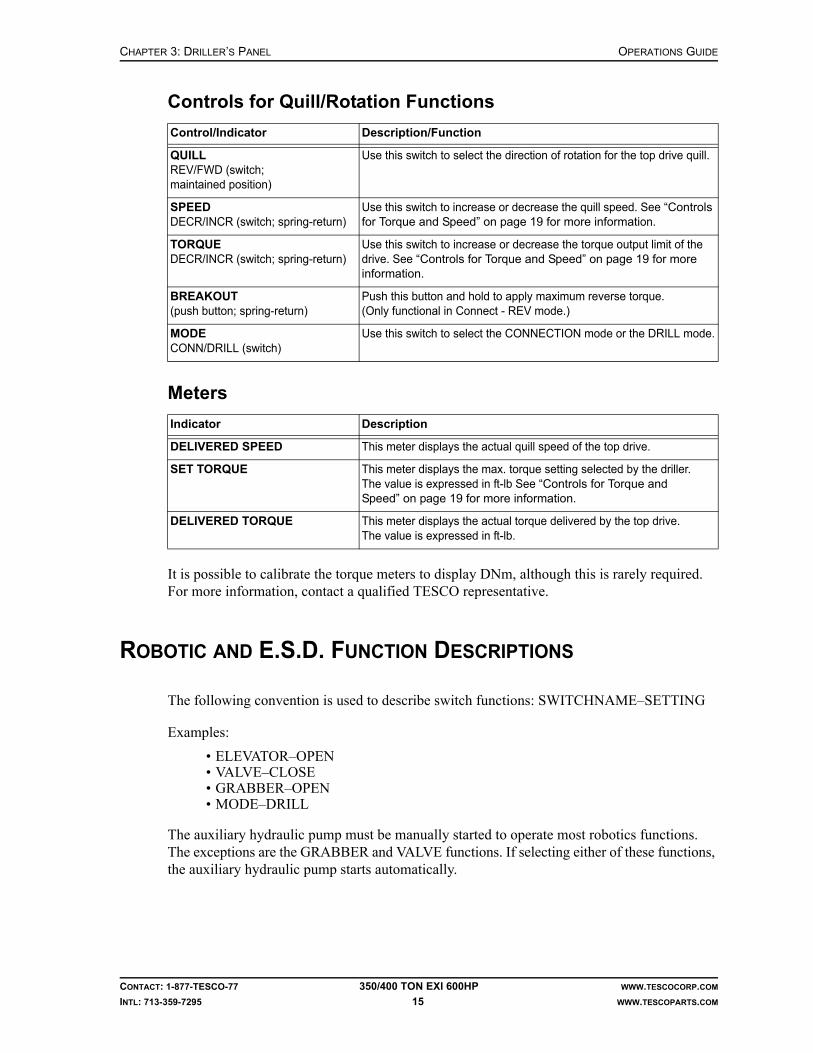
CHAPTER 3: DRILLER’S PANEL OPERATIONS GUIDE
CONTACT: 1-877-TESCO-77 350/400 TON EXI 600HP WWW.TESCOCORP.COM
INTL: 713-359-7295 15 WWW.TESCOPARTS.COM
Controls for Quill/Rotation Functions
Meters
It is possible to calibrate the torque meters to display DNm, although this is rarely required. For more information, contact a qualified TESCO representative.
ROBOTIC AND E.S.D. FUNCTION DESCRIPTIONS
The following convention is used to describe switch functions: SWITCHNAME–SETTING
Examples:
• ELEVATOR–OPEN• VALVE–CLOSE• GRABBER–OPEN• MODE–DRILL
The auxiliary hydraulic pump must be manually started to operate most robotics functions. The exceptions are the GRABBER and VALVE functions. If selecting either of these functions, the auxiliary hydraulic pump starts automatically.
Control/Indicator Description/Function
QUILLREV/FWD (switch;maintained position)
Use this switch to select the direction of rotation for the top drive quill.
SPEEDDECR/INCR (switch; spring-return)
Use this switch to increase or decrease the quill speed. See “Controls for Torque and Speed” on page 19 for more information.
TORQUEDECR/INCR (switch; spring-return)
Use this switch to increase or decrease the torque output limit of the drive. See “Controls for Torque and Speed” on page 19 for more information.
BREAKOUT(push button; spring-return)
Push this button and hold to apply maximum reverse torque. (Only functional in Connect - REV mode.)
MODECONN/DRILL (switch)
Use this switch to select the CONNECTION mode or the DRILL mode.
Indicator Description
DELIVERED SPEED This meter displays the actual quill speed of the top drive.
SET TORQUE This meter displays the max. torque setting selected by the driller. The value is expressed in ft-lb See “Controls for Torque and Speed” on page 19 for more information.
DELIVERED TORQUE This meter displays the actual torque delivered by the top drive. The value is expressed in ft-lb.

OPERATIONS GUIDE CHAPTER 3: DRILLER’S PANEL
CONTACT: 1-877-TESCO-77 350/400 TON EXI 600HP WWW.TESCOCORP.COM
INTL: 713-359-7295 16 WWW.TESCOPARTS.COM
ELEVATOR Function
The hydraulic elevators attach to the end of the elevator links. They clamp around and manipulate drill pipe, collars, drilling tools and casing.
Safety features for the elevators include a double-action OPEN switch. The 3-position ELEVATOR switch on the driller’s panel works in conjunction with the elevator SAFETY OPEN push button. To open the elevators, turn the ELEVATOR switch to ‘OPEN’ and press the SAFETY OPEN push button at the same time; this prevents accidental opening of the elevators. Operating either switch by itself will not energize the elevator solenoid. Additionally, the switch and the push button are ‘spring-return to neutral’, ensuring that both have to be manually selected each time ELEVATOR-OPEN is required.
Another safety feature for the elevators is ensuring that the elevators fully close and latch. When selecting ‘ELEVATOR–CLOSE’ at the driller’s panel, pressure to the CLOSE circuit remains high for enough time to positively engage the latch.
The driller can also use the CLOSE button on the brake handle to close the elevators. This allows the driller to close the elevators (and lower or raise the drawworks) by using one hand, and leaves the other hand free to operate other drilling controls.
TILT Function
The TILT function allows the operator to move the elevator links (with the attached elevators) to a position forward or back of hole center (the links move up to 55° forward and up to 35° back of hole center). Use the TILT function to manipulate pipe stands when tripping pipe, run-ning casing, and making up pipe stands. Use the TILT function in conjunction with other func-tions to rack back pipe stands, make up pipe stands in the mouse hole, and retrieve pipe stands for reconnection.
Use the TILT–BACK function to move the links and elevators out of the way and lower the top drive closer to the rig floor, or to reposition the links to an angle back of hole center.
Use the TILT–FWD function to move the links and elevators away from hole center and toward the V-door.
The FLOAT function returns the links to hole center. When pushing the FLOAT button on the driller’s panel, this relieves the pressure in the TILT cylinders and the links return to a vertical position below the top drive.
EXTEND Function
Use the EXTEND function to handle stands of drill pipe during tripping, or to handle rig tools when the top drive is not over hole center. The EXTEND function moves the entire top drive away from the torque track to a maximum distance of 60 in (1.5 m).

CHAPTER 3: DRILLER’S PANEL OPERATIONS GUIDE
CONTACT: 1-877-TESCO-77 350/400 TON EXI 600HP WWW.TESCOCORP.COM
INTL: 713-359-7295 17 WWW.TESCOPARTS.COM
The EXTEND switch on the driller’s panel is ‘spring-return to neutral’, which means it must be held in the desired position to activate the function. This allows the operator to stop the top drive at any point along its travel path by releasing the switch. Operators can also ‘jog’ (move in small increments) the top drive along its travel path by momentarily selecting EXTEND–IN or EXTEND–OUT.
Use the EXTEND–OUT function to move the top drive away from the torque track and towards the V-door. This enables the operator to handle stands of drill pipe more effectively when additional distance from hole center is desired. Combine this function with the TILT–FORWARD function to achieve maximum extension of the top drive.
Use EXTEND–IN to move the top drive towards its original position over hole center.
VALVE Function
The VALVE function operates the mud valve actuator, which opens and closes the mudsaver section of the mud valve. The mud valve is a double-ball valve. The lower ball is used for well control and the upper ball is used as a mudsaver.
The mud pump(s) must be deactivated when making or breaking pipe joints. Use the VALVE function to close the mudsaver valve to prevent gravity loss of drilling fluid that is trapped in the swivel, quill and hose.
When selecting VALVE–CLOSE at the driller’s panel, electrical controls stop the quill rotation. The valve closes and an eight-second timer activates. After the timer expires, restart the quill rotation by setting the QUILL switch to neutral, then to ‘FWD’ or ‘REV’.
Note: When the mud pump interlock is properly installed it will prevent the mud pump from starting if the valve is closed.
When selecting ‘VALVE–CLOSE’, a yellow warning light illuminates on the driller’s panel and remains lit until ‘VALVE–OPEN’ is selected.
GRABBER Function
The grabber is a hydraulically operated device used to clamp onto and hold pipe. It is located at the bottom of the grabber leg of the top drive. The grabber is used as break-out tongs for making or breaking pipe stand joints to or from the top drive.
The GRABBER–OPEN switch on the driller’s panel is ‘spring-return to neutral’, and it requires only momentary functioning to begin the OPEN sequence. The GRABBER–CLOSE switch is ‘maintained’, which means that it maintains power to the CLOSE hydraulic direc-tional valves until the operator manually turns the switch to the neutral position.
The yellow GRABBER ‘CLOSED’ warning light on the driller’s panel illuminates when selecting the GRABBER–CLOSE function.
TESCO recommends installing safety interlocks that prevent the operator from hoisting the drawworks when the grabber is closed (unless the operator presses an override button on the brake handle). A separate PLC-programmed interlock prevents the grabber from closing if the quill speed is greater than 5 rpm.

OPERATIONS GUIDE CHAPTER 3: DRILLER’S PANEL
CONTACT: 1-877-TESCO-77 350/400 TON EXI 600HP WWW.TESCOCORP.COM
INTL: 713-359-7295 18 WWW.TESCOPARTS.COM
PIPE HANDLER Function
The pipe handler section of the top drive is located from the slewing bearing down, and is designed to rotate independently of the Swivel gearbox of the top drive. The pipe handler allows the operator to handle pipe stands and downhole tools easily and conveniently.
The pipe handler section is locked to the swivel gearbox of the top drive at the slewing bearing. The PIPE HANDLER switch on the driller’s panel must be set to ‘UNLOCK’ before accessing the ROTATE function. The Pipe Handler is independently driven by a hydraulic motor and does not utilize the electric drive system.
The direction of rotation for the pipe handler is determined by the pipe handler REV/FWD switch. 360° rotation is available. Release the REV/FWD switch to stop rotation. The pipe handler rotates at approximately 4 rpm, but may be adjusted using the flow control valves next to the hydraulic motor. The pipe handler rotates at a fixed speed of approximately 8 rpm.
A yellow CAUTION light illuminates at the driller's panel when the pipe handler is ‘UNLOCKED’.
Emergency Shut Down (E.S.D.)
There are two E.S.D. circuits, each with its own specific function.
E.S.D. on the Driller's Panel
Push the E.S.D. button on the driller's panel to trip the main circuit breaker (the breaker supplies 600 VAC to the ACS800 drive and is located in the power module building). This removes all high voltage power from the drive. The quill stops rotating. This E.S.D. also deactivates the auxiliary hydraulic pump. All devices that operate or rotate at the drill floor become inactive.
When resetting (pulling out) the E.S.D. switch, the auxiliary pump can be activated from the driller’s panel, however, power cannot be activated for the drive system from the driller’s panel. Follow standard start-up procedures to restart the drive.
E.S.D. on the Main Panel Control System
Push the E.S.D. button on the door of the power module main panel to cut all power to the TESCO power module. This E.S.D. switch is interlocked to trip the breaker for the main service power supply.
Reset E.S.D
The E.S.D. button has spring-return. Reset and activate the main breaker to restore power to the power module.

CHAPTER 3: DRILLER’S PANEL OPERATIONS GUIDE
CONTACT: 1-877-TESCO-77 350/400 TON EXI 600HP WWW.TESCOCORP.COM
INTL: 713-359-7295 19 WWW.TESCOPARTS.COM
CONTROLS FOR TORQUE AND SPEED
The torque and quill speed that is available is specific to each top drive activity. They are summarized in the following table.
* Refer to “How to Set or Change Drive Parameters” on page 26.
The operator uses the driller’s panel to access the torque and speed functions, and to set the torque and speed limits.
DRILL Forward
DRILL Forward mode is achieved by turning the MODE switch to DRILL, and the QUILL switch to FWD.
Torque
Controls on the driller’s panel allow the operator to increase or decrease the quill torque to suit various tool joints as required during drilling operations. The operator can select from 0 to 100% of the maximum preset torque limit. Preset the maximum torque limit at the driller’s panel before operating the unit (see “How to Set or Change Drive Parameters” on page 26).
Speed
Controls on the driller’s panel allow the operator to increase or decrease the quill speed as required during drilling operations. The full range of the quill speed is available in DRILL Forward mode. Quill speed ranges from 0 to 220 rpm.
DRILL Reverse
DRILL Reverse mode is achieved by turning the MODE switch to DRILL, and the QUILL switch to REV.
Torque
Controls on the driller’s panel allow the operator to increase or decrease the quill torque as required during reverse drilling operations. The operator can select from 0 to 100% of the maximum preset torque limit. Preset the maximum limit at the driller’s panel before operating the unit (see “How to Set or Change Drive Parameters” on page 26).
Table 3-2: Available torque and quill speed
Mode Available Torque Available Speed
DRILL (FWD) 0 to 100% of the maximum preset value* 0 to maximum rpm
DRILL (REV) 0 to 100% of the maximum preset value* 0 to 30 rpm (11.11:1 gear ratio)
CONNECT (FWD) 0 to 100% of the maximum preset value* 0 to maximum rpm
CONNECT (REV) 0 to 100% of the maximum preset value* 0 to 30 rpm (11.11:1 gear ratio)

OPERATIONS GUIDE CHAPTER 3: DRILLER’S PANEL
CONTACT: 1-877-TESCO-77 350/400 TON EXI 600HP WWW.TESCOCORP.COM
INTL: 713-359-7295 20 WWW.TESCOPARTS.COM
Speed
Only one speed is available during reverse drilling operations. The operator presets the DRILL Reverse speed limit at the driller's panel before operating the unit (see “How to Set or Change Drive Parameters” on page 26). The available settable speed in DRILL Reverse mode is 0 to 30 rpm.
CONNECT Forward
CONNECT Forward mode is achieved by setting the MODE switch to CONN, and the QUILL switch to ‘FWD’.
Torque
Controls on the driller’s panel allow the operator to increase or decrease the quill torque to suit various tool joints as required when making connections. The operator can select from 0 to 100% of the maximum preset torque limit. Preset the maximum connect torque limit at the driller's panel before operating the unit (see “How to Set or Change Drive Parameters” on page 26).
Speed
Only one speed is available in CONNECT Forward mode. The operator presets the CON-NECT Forward speed limit at the driller’s panel before operating the unit (see “How to Set or Change Drive Parameters” on page 26).
CONNECT Reverse
Torque
Only one torque setting is available in CONNECT Reverse mode (unless the operator presses the BREAKOUT button). The operator presets the torque limit at the driller’s panel before operating the unit.
Speed
Only one speed setting is available in CONNECT Reverse mode (unless the operator presses the BREAKOUT button). The operator sets the CONNECT Reverse speed limit at the driller’s panel before operating the unit (see “How to Set or Change Drive Parameters” on page 26).
BREAKOUT Button
Press and hold the BREAKOUT button to apply maximum reverse torque to the pipe joint. The torque increases from preset Connect-Reverse torque to the maximum available torque.

CHAPTER 3: DRILLER’S PANEL OPERATIONS GUIDE
CONTACT: 1-877-TESCO-77 350/400 TON EXI 600HP WWW.TESCOCORP.COM
INTL: 713-359-7295 21 WWW.TESCOPARTS.COM
If the pipe joint breaks before the top drive reaches maximum torque, the top drive rotates at the preset BREAKOUT speed. When releasing the BREAKOUT button, the top drive rotates at the preset CONNECT Reverse speed, if this is selected. The system remains in a ‘ready’ state and no temporary shut down occurs.
Dual Function Remote Brake Handle Control
The push button controls on the brake handle operate the ELEVATOR–CLOSE and the GRABBER–Drawworks Interlock Override as described below.
ELEVATOR–CLOSE
To make tripping operations easier, close the elevators from a switch located on the brake handle. This is a ‘spring-return’ push button that activates a timed sequence (eight seconds) to ensure that the elevators close completely. The eight-second sequence activates even if the button is only briefly selected.
GRABBER–Drawworks Interlock Override
The interlock for the drum brake locks out the drum clutch so the driller cannot hoist while the grabber is engaged. A yellow warning light located above the GRABBER switch on the driller’s panel indicates the status of the grabber. If this light is illuminated, it indicates that GRABBER–CLOSE is selected. Use the push button on the brake handle to override the lockout feature.
Note: Use this override during directional drilling operations if the string needs to be hoisted when the grabber is closed.
The override button operates a temporary contact that either a) controls an air valve that allows air back to the drum clutch or b) triggers a PLC signal that interrupts the drawworks controls. The override works only when the button is pushed and held. When the button is released, air supply to the clutch control or the PLC interlock with the drawworks control is once again interrupted and the override is no longer active.
HOW TO CALIBRATE THE METERS ON THE DRILLER’S PANEL
The driller’s panel contains four display meters:
• SET SPEED (rpm)• DELIVERED SPEED (rpm)• SET TORQUE (ft-lb)• DELIVERED TORQUE (ft-lb)
Use the following procedure to calibrate all meters before EVERY job. Recommended settings appear in the tables that follow the procedure.
Although the values are different for each type of meter, calibrate all meters using the same procedure.
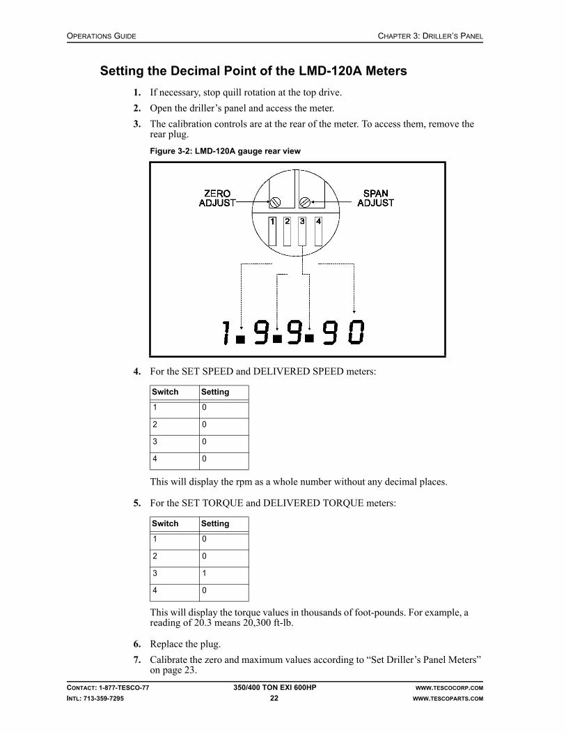
OPERATIONS GUIDE CHAPTER 3: DRILLER’S PANEL
CONTACT: 1-877-TESCO-77 350/400 TON EXI 600HP WWW.TESCOCORP.COM
INTL: 713-359-7295 22 WWW.TESCOPARTS.COM
Setting the Decimal Point of the LMD-120A Meters
1. If necessary, stop quill rotation at the top drive.
2. Open the driller’s panel and access the meter.
3. The calibration controls are at the rear of the meter. To access them, remove the rear plug.
4. For the SET SPEED and DELIVERED SPEED meters:
This will display the rpm as a whole number without any decimal places.
5. For the SET TORQUE and DELIVERED TORQUE meters:
This will display the torque values in thousands of foot-pounds. For example, a reading of 20.3 means 20,300 ft-lb.
6. Replace the plug.
7. Calibrate the zero and maximum values according to “Set Driller’s Panel Meters” on page 23.
Figure 3-2: LMD-120A gauge rear view
Switch Setting
1 0
2 0
3 0
4 0
Switch Setting
1 0
2 0
3 1
4 0

CHAPTER 3: DRILLER’S PANEL OPERATIONS GUIDE
CONTACT: 1-877-TESCO-77 350/400 TON EXI 600HP WWW.TESCOCORP.COM
INTL: 713-359-7295 23 WWW.TESCOPARTS.COM
Set Driller’s Panel Meters
Calibrate driller’s panel meters. To calibrate the specific meters used in the 350/400 TON EXI 600HP top drive, refer to “How to Calibrate the Meters on the Driller’s Panel” on page 21.”
Inspection Point Data/Notes
SET SPEED meter SET SPEED meter calibration: Set meter dip-switch setting to 0000 (verify with electrical engineering department) Using loop calibrator, set ZERO ADJUST (zero) and SPAN ADJUST (max) until meter displays the following values:
4 mA = 0 rpm20 mA = 220 rpm
Repeat ZERO ADJUST and SPAN ADJUST and adjust if necessary
Repeat ZERO ADJUST and SPAN ADJUST again and adjust if necessary
DELIVERED SPEED meter DELIVERED SPEED meter calibration: Set meter dip-switch setting to 0000 (verify with electrical engineering department) Using loop calibrator, adjust set ZERO ADJUST (zero) and SPAN ADJUST (max) until meter displays the following values:4 mA = -220 rpm20 mA = 220 rpm Repeat ZERO ADJUST and SPAN ADJUST and adjust if
necessary Repeat ZERO ADJUST and SPAN ADJUST again and adjust if
necessary
SET TORQUE meter SET TORQUE meter calibration: Set meter dip-switch setting to 0010 (verify with electrical engineering department) Using loop calibrator, set ZERO ADJUST (zero) and SPAN ADJUST (max) until meter displays the following values:4 mA = 0 ft-lb20 mA = 45.0 (×1000) ft-lb
Repeat ZERO ADJUST and SPAN ADJUST and adjust if necessary
Repeat ZERO ADJUST and SPAN ADJUST again and adjust if necessary
DELIVERED TORQUE meter DELIVERED TORQUE meter calibration: Set meter dip-switch setting to 0010 (verify with electrical engineering department) Using loop calibrator, set ZERO ADJUST (zero) and SPAN ADJUST (max) until meter displays the following values:4 mA = 0 ft-lb20 mA = 45.0 (×1000) ft-lb
Repeat ZERO ADJUST and SPAN ADJUST and adjust if necessary
Repeat ZERO ADJUST and SPAN ADJUST again and adjust if necessary

OPERATIONS GUIDE CHAPTER 3: DRILLER’S PANEL
CONTACT: 1-877-TESCO-77 350/400 TON EXI 600HP WWW.TESCOCORP.COM
INTL: 713-359-7295 24 WWW.TESCOPARTS.COM
This page has been left blank intentionally.

CHAPTER 4: TORQUE AND SPEED LIMITS OPERATIONS GUIDE
CONTACT: 1-877-TESCO-77 350/400 TON EXI 600HP WWW.TESCOCORP.COM
INTL: 713-359-7295 25 WWW.TESCOPARTS.COM
CHAPTER 4: TORQUE AND SPEED LIMITS
OVERVIEW
The torque that the top drive can develop is related to the rotational speed of the quill. The relationship between quill rotational speed and maximum drilling torque is nonlinear, as seen in Figure 4-1.
Figure 4-1: EXI 600 Torque Curve

OPERATIONS GUIDE CHAPTER 4: TORQUE AND SPEED LIMITS
CONTACT: 1-877-TESCO-77 350/400 TON EXI 600HP WWW.TESCOCORP.COM
INTL: 713-359-7295 26 WWW.TESCOPARTS.COM
The top drive can produce a maximum continuous drilling torque of 30,000 ft-lb (40,680 N-m) at speeds up to 90 rpm. From 90 rpm up to the maximum speed of 220 rpm, the maximum drilling torque decreases from 30,000 to 12,000 ft-lb (40,680 to 16,272 N-m).
The torque value of 39,000 ft-lb (52,884 N-m) corresponds to the top drive’s maximum makeup torque. This is the torque necessary to connect (‘make’) drill pipe connections at low speed (0 to 30 rpm).
The torque value of 45,000 ft-lb (61,020 N-m) corresponds to the top drive’s breakout torque. This is the torque necessary to disconnect (‘break’) drill pipe connections at very low speed (0 to 8 rpm).
DRIVE PARAMETERS
Overview
The following drive parameters (torque and speed settings) can be set and changed at the driller’s panel:
• DRILL Forward - Torque• DRILL Reverse - Torque and Speed• CONNECT Forward - Torque and Speed• CONNECT Reverse - Torque and Speed• BREAKOUT - Speed
Set the drive parameters for torque and speed to minimize the possibility of injury to personnel and damage to drilling equipment.
For example, limit the torque setting for the DRILL Forward function to help prevent the drill string from twisting off during drilling operations. Limit the speed and torque settings for the CONNECT function to promote the proper make up of tool joints and guard against damage to threads and seal faces caused by over-torquing.
The drive system will not surpass the programmed torque and speed settings, however, the following procedure can be used to change the settings if required.
Use the same steps to set or change a setting for all functions.
How to Set or Change Drive Parameters
This procedure can be performed only if the drive system is disabled.
Danger! Release all torque in the drill before disabling the drive system or damage to the electrical components might occur.
1. At the driller's panel, turn the ENABLE switch to ‘OFF’.
2. Insert the key into the DRIVE SET keyed switch.
3. Turn and hold the key in the ‘SET’ position.
!

CHAPTER 4: TORQUE AND SPEED LIMITS OPERATIONS GUIDE
CONTACT: 1-877-TESCO-77 350/400 TON EXI 600HP WWW.TESCOCORP.COM
INTL: 713-359-7295 27 WWW.TESCOPARTS.COM
4. Use the procedures in the following table to set the required parameter(s):
5. Release the DRIVE SET keyed switch.
6. Remove the key.
7. Push and hold the RESET button for 5 seconds.
8. Set the ENABLE switch to ‘ON’.
Table 4-1: How to set or change drive parameters
To set this parameter Perform these steps
DRILL ForwardTorque
1. Set the MODE switch to DRILL. 2. Set the QUILL switch to FWD.3. Use the TORQUE switch to increase or decrease the SET TORQUE value on
the digital gauge on the driller's panel.Note: Set this limit at 2,000 ft-lb (2,712 N-m) less than the lowest connected joint torque setting (see CONNECT Forward Torque). Consult the Rig Manager or Oil Company Representative to determine the proper setting.Important: If using a downhole mud motor, the torque set limit must be higher than the maximum output of the mud motor.
DRILL ReverseSpeed and Torque
1. Set the MODE switch to DRILL2. Set the QUILL switch to REV.3. Use the SPEED switch to increase or decrease the SET SPEED value on the
digital gauge on the driller's panel.Note: TESCO recommends 10 rpm or less.
4. Use the TORQUE switch to increase or decrease the SET TORQUE value on the digital gauge on the driller's panel.Note: TESCO recommends 10,000 ft-lb (13,560 N-m) or less, depending on the drill string configuration.
CONNECT ForwardSpeed and Torque
1. Set the MODE switch to CONN.2. Set the QUILL switch to FWD.3. Use the SPEED switch to increase or decrease the SET SPEED value on the
digital gauge on the driller's panel.Note: TESCO recommends 15 rpm or less.
4. Use the TORQUE switch to increase or decrease the SET TORQUE value on the digital gauge on the driller's panel.Note: Use the torque requirements for the drill string connections to determine this setting.
CONNECT ReverseSpeed and Torque
1. Set the MODE switch to CONN.2. Set the QUILL switch to REV.3. Use the SPEED switch to increase or decrease the SET SPEED value on the
digital gauge on the driller's panel.Note: TESCO recommends 15 rpm or less.
4. Use the TORQUE switch to increase or decrease the SET TORQUE value on the digital gauge on the driller's panel.Note: TESCO recommends 8,000 ft-lb (10,848 N-m) or less.
BREAKOUT Speed Breakout speed is set to 7 rpm by PLC Logic and is not adjustable.

OPERATIONS GUIDE CHAPTER 4: TORQUE AND SPEED LIMITS
CONTACT: 1-877-TESCO-77 350/400 TON EXI 600HP WWW.TESCOCORP.COM
INTL: 713-359-7295 28 WWW.TESCOPARTS.COM
SETTING TORQUE LIMITS
In order not to exceed the torque limits of the pipe and threaded connections being used, the operator presets torque limits before operations begin. Failure to limit torque may result in damaged pipe and/or connections. Once set, these limits will not be exceeded by the top drive during operations.
The 350/400 EXI 600 top drive can produce 30,000 ft-lb (40,680 N-m) of nominal torque continuously, with 1.5 times overload capability. Therefore the torque lim-its should be set based on the ability of the motor and the drill pipe being used.
In Breakout, the torque will ramp up to maximum 45,000 ft-lb (61,020 N-m). This is the limit for breakout and is not adjustable.
If Connect-Forward/Reverse is selected, the drive will apply torque to the preset value for Connect-Forward/Reverse. For safety, the torque limit for Connect-Reverse is normally set very low to prevent accidental back-off.
Drill-Forward torque limit should be preset to remain within the limitations of the drill pipe being used. During operations, the full range of torque (from zero to the preset limit) is available to the operator. For safety, Drill-Reverse torque is nor-mally set very low, to prevent accidental back-off. If required, higher values can be preset. During operations, the full range of torque (from zero to the preset limit) is available to the operator. This feature allows fully-controlled back-off, if required.
Note: When operating at a speed higher than 90 rpm, the top drive will pro-duce less torque than nominal value.
Breakout
There is no need to set a torque limit for Breakout as the torque applied by the drive system is preprogrammed and unadjustable.
The breakout torque is pre-programmed to 45,000 ft-lb (61,020 N-m) which is the full overload capacity of the motor.
The Set Torque meter is the third one down on the set of four digital meter displays on the right side of the Driller’s Control Panel.
Note: For convenience, speed and torque limit settings can be done in sequence; that is, the operator can set the speed and then set the torque before proceeding to the next rotational function.

CHAPTER 4: TORQUE AND SPEED LIMITS OPERATIONS GUIDE
CONTACT: 1-877-TESCO-77 350/400 TON EXI 600HP WWW.TESCOCORP.COM
INTL: 713-359-7295 29 WWW.TESCOPARTS.COM
Connect Forward
It is recommended that the Connect-Forward torque limit be set to comply with the drill pipe connection specifications. Maximum achievable value is 39,000 ft-lb (52 884 N-m).
1. Ensure that the top drive quill is not rotating.
2. Function ENABLE switch to ‘OFF’.
3. Insert key into DRIVE SET switch, turn clockwise and ‘HOLD’.
4. Select CONN/DRILL switch to ‘CONN’.
5. Select QUILL FORWARD/REVERSE switch to ‘FORWARD’.
6. View SET TORQUE meter and adjust displayed value to desired value using the TORQUE INCREASE/DECREASE switch.
7. Release DRIVE SET switch.
The Connect Forward torque limit is now set.
Connect Reverse
It is recommended that the Connect Reverse torque limit be set at approximately 5,000 to 8,000 ft-lb (6 780 to 10 848 N-m).
1. Ensure that the top drive quill is not rotating.
2. Function ENABLE switch to ‘OFF’.
3. Insert key into DRIVE SET switch and turn clockwise and ‘HOLD’.
4. Select CONN/DRILL switch to ‘CONN’.
5. Select QUILL FORWARD/REVERSE switch to ‘REVERSE’.
6. View SET TORQUE meter and adjust displayed value to desired value using the TORQUE INCREASE/DECREASE switch.
7. Release DRIVE SET switch.
The Connect Reverse torque limit is now set.

OPERATIONS GUIDE CHAPTER 4: TORQUE AND SPEED LIMITS
CONTACT: 1-877-TESCO-77 350/400 TON EXI 600HP WWW.TESCOCORP.COM
INTL: 713-359-7295 30 WWW.TESCOPARTS.COM
Drill Forward
The unit has the capacity to Drill in Forward at a maximum quill speed of 220 rpm.
1. Ensure that the top drive quill is not rotating.
2. Function ENABLE switch to ‘OFF’.
3. Insert key into DRIVE SET switch and turn clockwise and ‘HOLD’.
4. Select CONN/DRILL switch to ‘DRILL’.
5. Select QUILL FORWARD/REVERSE switch to ‘FORWARD’.
6. View SET TORQUE (top) meter and adjust displayed value to desired value using the speed INCREASE/DECREASE switch.
7. Release DRIVE SET switch.
The Drill Forward torque limit is now set.
Drill Reverse
It is recommended that the Drill Reverse torque limit be set at approximately 5,000 to 8,000 ft-lb (6 780 to 10 848 N-m).
1. Ensure that the top drive quill is not rotating.
2. Function ENABLE switch to ‘OFF.’
3. Insert key into DRIVE SET switch, turn clockwise and ‘HOLD’.
4. Select CONN/DRILL switch to ‘DRILL’.
5. Select QUILL FORWARD/REVERSE switch to ‘REVERSE’.
6. View SET TORQUE meter and adjust displayed value to desired value using the TORQUE INCREASE/DECREASE switch.
7. Release DRIVE SET switch.
The Drill Reverse torque limit is now set.
PIPE HANDLER SETTINGS
Pipe Handler Speed
Warning! No person should be within the radius of link movement whenever the Pipe Handler Forward/Reverse switch is operated.
The pipe handler rotates approximately 4 rpm, but the operator may select any speed from 0 to 8 rpm. To modify speed, adjust the needle valves connected to the hydraulic oil supply and return lines of the rotate motor.
!

CHAPTER 5: OTHER PRE-OPERATIONAL PROCEDURES OPERATIONS GUIDE
CONTACT: 1-877-TESCO-77 350/400 TON EXI 600HP WWW.TESCOCORP.COM
INTL: 713-359-7295 31 WWW.TESCOPARTS.COM
CHAPTER 5: OTHER PRE-OPERATIONAL PROCEDURES
INSTALL THE SAVER SUB AND DIE LOCK CLAMP
1. Ensure the PIPE HANDLER switch is set to ‘LOCKED’.
2. Position the saver sub through the grabber box.Note: Ensure the upper pin protrudes above the grabber box.
3. Apply pipe dope to the threads of the saver sub.
4. Attach the saver sub by hand. Note: Tighten as much as possible.
5. Set the GRABBER switch to ‘CLOSE’.
6. Use the TORQUE switch to reduce the torque to approximately 30% of the required make up torque.
7. Set the MODE switch to ‘CONN’.
8. Set the QUILL switch to ‘FWD’.
9. Continue rotation until the connection is fully engaged.
10. Use the TORQUE switch to increase the torque to the torque required to make up the connection.
11. When desired torque is achieved, set the QUILL switch to neutral.
12. Set the GRABBER switch to ‘OPEN’.
13. Place the die lock clamp on top of the grabber box.
14. Loosely install the die lock bolts (8).
15. Raise the die lock clamp into position and hold, either manually or by using the GRABBER LIFT function
Note: Position the clamp so it evenly straddles the connection between the saver sub and the mud valve.
16. Apply anti-seize compound to all cap screws and tighten them all evenly.Note: Monitor the end gaps to ensure that the clamp is installed evenly.
17. Torque all 7/8 in. Grade 8 fasteners to 550 ft-lb (745 N-m).Note: For more information, refer to the appendix titled ‘Torque Specifica-tions for High Strength Fasteners’ in the Maintenance Guide for the unit.
18. Seat the dies.Note: To seat the dies, strike the back side of each half of the clamp as hard as possible with a sledge hammer.
19. When the dies seat properly, torque all bolts to 550 ft-lb (746 N-m).

OPERATIONS GUIDE CHAPTER 5: OTHER PRE-OPERATIONAL PROCEDURES
CONTACT: 1-877-TESCO-77 350/400 TON EXI 600HP WWW.TESCOCORP.COM
INTL: 713-359-7295 32 WWW.TESCOPARTS.COM
ORIENTING THE PIPE HANDLER
Take these precautions before operating the pipe handler:
• Ensure that the links and elevators are hanging vertically.• Ensure that the pipe handler is holding no reactive torque from the drill string. This
can be done by setting the GRABBER switch to ‘OPEN’.
1. Ensure the GRABBER OPEN/CLOSE switch is set to ‘OPEN’.
2. Using the PIPE HANDLER UNLOCK/LOCK switch, select ‘UNLOCK’.Note: The PIPE HANDLER CAUTION light will illuminate.
3. Select ‘PIPE HANDLER FWD/REV’ (depending on desired rotation).
4. When the desired position is reached, release the PIPE HANDLER FWD/REV switch to neutral.
5. Using the PIPE HANDLER UNLOCK/LOCK switch, select ‘LOCK’.
6. If the PIPE HANDLER CAUTION light remains illuminated, the lock has not engaged. Using the REV/FWD switch, rotate the pipe handler slightly until the CAUTION light turns off. This indicates the pipe handler is locked.
SETTING THE GRABBER HEIGHT
The grabber must close on the box connection of the drill string, just below the saver sub. The grabber height can be adjusted from the driller’s panel. To adjust the height, use the following procedure:
1. Determine if the grabber needs to move up or down to align with the connection of the drill string.
2. On the driller’s panel, select ‘OPEN’ on the GRABBER switch.Note: The auxiliary hydraulic pump will start automatically if it is not run-ning at this time.
3. On the driller’s panel, select ‘UP’ or ‘DOWN’ on the GRABBER LIFT switch and hold it there.
4. Release the GRABBER LIFT switch as soon as the grabber reaches the correct height.
5. The grabber height is now set.

CHAPTER 5: OTHER PRE-OPERATIONAL PROCEDURES OPERATIONS GUIDE
CONTACT: 1-877-TESCO-77 350/400 TON EXI 600HP WWW.TESCOCORP.COM
INTL: 713-359-7295 33 WWW.TESCOPARTS.COM
HOW TO ADJUST THE GRABBER-LIFT HEIGHT LIMIT
The grabber-lift height limit is the maximum height to which the grabber can be lifted from the driller’s panel. It is a safety feature incorporated in the grabber-lift circuit to ensure that the grabber is not accidentally lifted too high so it touches the connection lock above the saver sub and causes damage to the top drive.
The height limit can be adjusted to compensate for different heights of the connection clamp. It cannot be adjusted from the driller’s panel, however, it can be manually adjusted at the grabber lift manifold. The height limit adjustment is achieved by increasing or decreasing the stroke of the grabber lift cylinder. The means that by adjusting the grabber-lift height limit, the lower limit to which the grabber can be lowered to, is adjusted as well. This is usually not a problem as typically there is no equipment below the grabber that can cause interference when the grabber is lowered.
Follow the procedure below to decrease the grabber-lift height limit:
1. At the driller’s panel, set QUILL to neutral. Confirm there is no quill rotation.
2. At the rotary seal (see Figure 5-1 on page 34), open the needle valve.
3. Check to see if the grabber is opened. If not, at the driller’s panel select ‘OPEN’ on the GRABBER switch and ensure the grabber is fully opened.
4. At the driller’s panel, select and hold ‘DOWN’ on the GRABBER LIFT switch until the grabber stops lowering.
5. Release the GRABBER LIFT switch and allow it to return to neutral.
6. Close the needle valve.
7. Select and hold ‘UP’ on the GRABBER LIFT switch until it stops.
8. While still holding the GRABBER LIFT switch to ‘UP’, slowly open the needle valve (see Figure 5-1 on page 34). Watch while the grabber rises slowly.
Caution: Pinching hazard. Stay clear of the grabber while it is lifting.
9. Once the grabber reaches the desired height, close the needle valve.
10. Release the GRABBER LIFT switch and allow it to return to neutral.
11. Select ‘DOWN’ on the GRABBER LIFT switch and allow the grabber to lower about 6”.
12. Select ‘UP’ on the GRABBER LIFT switch and allow the grabber to rise until it stops. Release the GRABBER LIFT switch.
Confirm that the grabber has stopped at the desired grabber-lift height limit. The adjustment procedure is now complete.

OPERATIONS GUIDE CHAPTER 5: OTHER PRE-OPERATIONAL PROCEDURES
CONTACT: 1-877-TESCO-77 350/400 TON EXI 600HP WWW.TESCOCORP.COM
INTL: 713-359-7295 34 WWW.TESCOPARTS.COM
Follow the procedure below to increase the grabber-lift height limit:
1. At the driller’s panel, set QUILL to neutral. Confirm there is no quill rotation.
2. At the driller’s panel, select OPEN on the GRABBER switch.
3. At the driller’s panel, select and hold UP on the GRABBER LIFT switch until the grabber stops at the current height limit.
4. While still holding the GRABBER LIFT switch to UP, slowly open the needle valve, see Figure 4-1). Watch while the grabber rises slowly.
Caution: Pinching hazard. Stay clear of the grabber while it is lifting.
5. Once the grabber reaches the desired height, close the needle valve.
6. Release the GRABBER LIFT switch and allow it to return to neutral.
7. Select DOWN on the GRABBER LIFT switch and allow the grabber to lower about 6”.
8. Select UP on the GRABBER LIFT switch and allow the grabber to rise until it stops. Release the GRABBER LIFT switch.
9. Confirm that the grabber has stopped at the desired grabber-lift height limit. The adjustment procedure is now complete.
Figure 5-1: Rotary seal valve
CHAPTER 5: OTHER PRE-OPERATIONAL PROCEDURES OPERATIONS GUIDE
CONTACT: 1-877-TESCO-77 350/400 TON EXI 600HP WWW.TESCOCORP.COM
INTL: 713-359-7295 35 WWW.TESCOPARTS.COM
SETTING THE GRABBER CLOSING PRESSURE
The grabber hydraulic circuit incorporates a hydraulic oil pressure boosting device (intensifier), which allows the grabber to operate at much higher hydraulic pressure than the rest of the auxiliary hydraulic system. This results in much higher grabber clamping forces, very useful when using larger drill pipe sizes.
In some cases, when drilling with small pipe sizes, it may be necessary to reduce the grabber clamping force to avoid damaging the tool joints. This can be achieved by reducing the grabber closing hydraulic oil pressure. Follow the procedure below to adjust the grabber closing pressure:
1. Set the grabber switch to ‘OPEN’.
2. Using the GRABBER LIFT needle valves, position the grabber to close around the saver sub, or other suitable tubular which can withstand high clamping force.
3. Using the GRABBER OPEN/CLOSE switch, select ‘CLOSE’.
4. Read the grabber high pressure oil gauge located on the grabber intensifier mani-fold. The highest possible pressure is approximately 5,000 psi (34.4 MPa).
5. Adjust the pressure reducing valve using an allen key.Note: Clockwise rotation = increase; counter-clockwise rotation = decrease.
6. Monitor gauge pressure until the pressure reading is a the appropriate level, as described in Table 5-1 for corresponding drill pipe size.
7. Using the GRABBER OPEN/CLOSE switch, select ‘OPEN’, then ‘CLOSE’, and confirm gauge pressure. Re-adjust if necessary.

OPERATIONS GUIDE CHAPTER 5: OTHER PRE-OPERATIONAL PROCEDURES
CONTACT: 1-877-TESCO-77 350/400 TON EXI 600HP WWW.TESCOCORP.COM
INTL: 713-359-7295 36 WWW.TESCOPARTS.COM
Note: The oil pressure intensifier counterbalance valve is factory preset and should not be adjusted.
Figure 5-2: Grabber intensifier manifold
Table 5-1: Correct pressure for different drill pipe sizes
Drill Pipe Size Type of Connection Grabber Closing Pressure (psi)
3 1/2” NC38 (3 1/2 IF) 2,500 to 3,000
3 1/2” NC40 (4 FH) 3,000 to 3,500
4” NC40 (4 FH) 3,000 to 3,500
4” NC46 (4 IF) 3,500 to 4,000
4 1/2” NC46 (4 IF) & NC50 (4 1/4 IF) 4,000 to 4,500
5” and larger NC50 (4 1/2 IF) or larger 4,500 to 5,000 max

CHAPTER 6: MAKING/BREAKING CONNECTIONS OPERATIONS GUIDE
CONTACT: 1-877-TESCO-77 350/400 TON EXI 600HP WWW.TESCOCORP.COM
INTL: 713-359-7295 37 WWW.TESCOPARTS.COM
CHAPTER 6: MAKING/BREAKING CONNECTIONS
WARNINGS
Mudsaver Valve
When operating the mudsaver valve, the valve switch applies pressure to the actuator. If the quill rotates with pressure applied, seal damage can result. Because of this, a mudsaver inter-lock stops the quill rotation for five seconds while the valve operates.
If operating the mudsaver VALVE switch while the quill is rotating, an interlock in the PLC program prevents damage to the actuator seals as follows:
• The PLC program stops quill rotation. • The PLC allows the mudsaver valve to complete its timed circuit.
When the circuit is complete, the top drive will restart automatically.
Pipe Slips
Danger! Always use caution when setting and removing pipe slips. If setting the slips when the rotary table is locked, this might trap torque in the drill string. When removing the slips, any trapped torque might release and turn the drill string. Hoist the drill string free of the slips before removing the slips.
!

OPERATIONS GUIDE CHAPTER 6: MAKING/BREAKING CONNECTIONS
CONTACT: 1-877-TESCO-77 350/400 TON EXI 600HP WWW.TESCOCORP.COM
INTL: 713-359-7295 38 WWW.TESCOPARTS.COM
HOW TO MAKE CONNECTIONS–GENERAL
Do the following before beginning this procedure:
• Ensure that correct torque and speed settings are preset into the drive system.• Ensure the torque and speed settings are appropriate for the drill string and drilling
conditions.• Ensure that the thread on the saver sub matches the thread on the drill string.• Properly apply pipe dope to all threaded connections.
Caution: When connecting the top drive to a single length of drill pipe, position the grabber so that it closes on the drill pipe tool joint. When making up the top drive and additional connections simultaneously, position the break-out tongs on the drill pipe tool joint located in the slips.
1. Set the MODE switch to ‘CONN’.
2. Set the QUILL switch to ‘FWD’.Note: The top drive turns at the pre-selected rpm for CONNECT mode with forward rotation.
Figure 6-1: Correct tong position to make a connection
!

CHAPTER 6: MAKING/BREAKING CONNECTIONS OPERATIONS GUIDE
CONTACT: 1-877-TESCO-77 350/400 TON EXI 600HP WWW.TESCOCORP.COM
INTL: 713-359-7295 39 WWW.TESCOPARTS.COM
3. Apply back-up tong to tool joint in the slips.Note: If making up the top drive and lower connection at the same time, apply the back-out tong below the lower connection. If making up a top drive connection only, apply the break-out tong to the single length of pipe. In this case, use the grabber instead of a break-out tong.
4. Slowly lower the top drive to the connection.
5. Ensure that the box connection enters into the drill pipe guide.
6. Monitor the weight indicator gauge.
7. Continue to lower the top drive until the weight indicator begins to fluctuate.
Caution: Ensure that the Vernier dampening valve (located on the weight indicator) is open.
8. Lead the top drive into the connection.Note: Lower the top drive in small increments as the connection rotates in. Keep a small amount of weight on the connection (i.e. the weight indi-cator should register only a small amount of weight). This prevents the top drive from “lifting” the stand or single section of drill pipe and damaging the threaded connections.
9. Continue forward rotation until the connection is fully engaged.Note: The top drive stalls when it reaches the preset SET torque. The for-ward rotation speed then drops to zero.
10. Use the TORQUE switch to increase the torque setting to the torque required for the current connection and thread type.
11. Monitor the DELIVERED TORQUE gauge.
12. When the DELIVERED TORQUE gauge displays the desired make up torque value, set the QUILL switch to NEUTRAL.
13. Wait until the DELIVERED TORQUE gauge value decreases to zero.
14. Remove the back-up tong, or open the grabber (if used).
How to Use the Mousehole to Connect Drill Pipe to the Top Drive
Pipe Handler Orientation–Grabber to V-door
Use this procedure when drilling with single lengths of pipe.
Note: This procedure applies when making connections when the mousehole is not off-set.
Caution: Ensure that the tilt links are close to hole center when hoisting pipe out of the mousehole with the pipe handler in this orientation. This will prevent the links from hitting the torque track.
1. Put a single length of pipe in the mousehole.
2. Apply pipe dope to the box connection on the drill pipe.
3. Set the EXTEND switch to ‘OUT’.
4. Extend the top drive until it is situated directly over the mousehole.
!
!

OPERATIONS GUIDE CHAPTER 6: MAKING/BREAKING CONNECTIONS
CONTACT: 1-877-TESCO-77 350/400 TON EXI 600HP WWW.TESCOCORP.COM
INTL: 713-359-7295 40 WWW.TESCOPARTS.COM
5. Lower the top drive until the elevator and elevator links are near the rig floor.
6. Using the TILT FWD/BACK switch, select ‘BACK’.
7. Move the elevator links and elevators backward and out of the way of the connec-tion.
8. Lower the top drive until the saver sub is within a foot of the pipe connection.
9. Using the MODE switch, select ‘CONN’.
10. Using the QUILL switch, select ‘FWD’.
11. Using the TORQUE switch, set torque to 30% of required torque.Note: Ensure the top drive and the single length of pipe are aligned to avoid cross-threading.
12. Slowly lower the top drive to engage the connection between the saver sub and the drill pipe.
13. Lead the top drive into the connection.Note: If the pipe starts to spin in the mousehole, set the QUILL switch to neutral. Close the grabber on the tool joint of the drill pipe, then set the QUILL switch to ‘FWD’.
14. When the connection is fully engaged (shoulders up), set the QUILL switch to neutral.
15. Complete the connection as described in one of the following procedures:• “How to Fully Torque a Connection” on page 42.• “How to Connect a Single Length of Drill Pipe to the Drill String” on page 42.
Figure 6-2: Correct position for elevator links and elevator

CHAPTER 6: MAKING/BREAKING CONNECTIONS OPERATIONS GUIDE
CONTACT: 1-877-TESCO-77 350/400 TON EXI 600HP WWW.TESCOCORP.COM
INTL: 713-359-7295 41 WWW.TESCOPARTS.COM
Pipe Handler Orientation–Grabber to Drawworks
Use this procedure when connecting the occasional individual single length of pipe from the mousehole to the drill string.
Caution: Ensure that the tilt links are close to the drill pipe when hoisting pipe out of the mousehole with the pipe handler in this orientation. This will prevent the racking platform from being hit.
1. Ensure a single length of pipe is located in the mousehole.
2. Properly dope the drill pipe box connection.
3. Using the EXTEND switch, select ‘OUT’.
4. Extend the top drive until it is situated directly over the mousehole.
5. Lower the top drive until it is near the rig floor.
6. Set the TILT switch to ‘BACK’.
7. Move the links and elevators backward and out of the way of the connection.
8. Lower the top drive until the saver sub is within 1 ft of the pipe connection.
9. Set the MODE switch to ‘CONN’.
10. Set the QUILL switch to ‘FWD’.
Figure 6-3: Elevator links and elevator position with grabber to drawworks
!

OPERATIONS GUIDE CHAPTER 6: MAKING/BREAKING CONNECTIONS
CONTACT: 1-877-TESCO-77 350/400 TON EXI 600HP WWW.TESCOCORP.COM
INTL: 713-359-7295 42 WWW.TESCOPARTS.COM
11. Use the TORQUE switch to decrease the torque value to 30% of preset torque value.
Note: Properly align the top drive and drill pipe to avoid cross-threading.
12. Slowly lower the top drive to engage the connection between the saver sub and the drill pipe.
13. Lead the top drive into the connection.Note: If the pipe starts to spin in the mousehole, set the QUILL switch to NEUTRAL. Close the grabber on the drill pipe tool joint, then set the QUILL switch to ‘FWD’.
14. When the connection is fully engaged, set the QUILL switch to neutral (and open the grabber if necessary).
15. Complete the connection using one of the following procedures:• “How to Fully Torque a Connection” on page 42.• “How to Connect a Single Length of Drill Pipe to the Drill String” on page 42.
How to Fully Torque a Connection
1. Ensure the pipe handler is ‘LOCKED’.
2. Set the GRABBER switch to ‘CLOSE’.
3. Set the MODE switch to ‘CONN’.
4. Set the QUILL switch to ‘FWD’.
5. Use the TORQUE switch to increase the SET TORQUE to make up torque value required for the current connection and thread type.
6. When the torque value matches the value required to fully torque the connection to specification, set the QUILL switch to neutral.
7. Set the GRABBER switch to ‘OPEN’.
How to Connect a Single Length of Drill Pipe to the Drill String
1. Hoist the single length of pipe out of the mousehole without torquing the connection.
2. Set the EXTEND switch to ‘IN’.
3. Retract the extend arms until the top drive is positioned over hole center.
4. Place break-out tongs on the tool joint of the drill pipe that is held by the rig slips.
5. Apply pipe dope to the tool joint box.
6. Lower the top drive to stab the drill pipe into the tool joint box of the drill pipe held in the rig slips.
7. Use the TORQUE switch to decrease the torque setting to 40-50% of the present value.
8. Set the MODE switch to ‘CONN’.
9. Set the QUILL switch to ‘FWD’.
10. Lead the top drive into the connection.
11. When the connection fully engages, use the TORQUE switch to set the make up torque required for the current connection and thread type.

CHAPTER 6: MAKING/BREAKING CONNECTIONS OPERATIONS GUIDE
CONTACT: 1-877-TESCO-77 350/400 TON EXI 600HP WWW.TESCOCORP.COM
INTL: 713-359-7295 43 WWW.TESCOPARTS.COM
12. Monitor the DELIVERED TORQUE gauge.
13. When the torque reaches the required torque value to make up the current connec-tion, set the QUILL switch to neutral.
Figure 6-4: Connect a single length of pipe to the drill string

OPERATIONS GUIDE CHAPTER 6: MAKING/BREAKING CONNECTIONS
CONTACT: 1-877-TESCO-77 350/400 TON EXI 600HP WWW.TESCOCORP.COM
INTL: 713-359-7295 44 WWW.TESCOPARTS.COM
HOW TO BREAK THE TOP DRIVE/DRILL PIPE CONNECTION
1. Position grabber to close on the box of the drill pipe.
Caution: Ensure that the grabber will not close on any part of the saver sub or the hard band of the drill pipe.
2. Ensure the PIPE HANDLER is locked.
Danger! this is an important safety step.
3. Set the GRABBER switch to ‘CLOSE’.
4. Set the MODE switch to ‘CONN’.
5. Set the QUILL switch to ‘REV’.
6. Wait until the delivered torque meter indicates that delivered torque has increased to the preset value.
7. Push and hold the BREAKOUT button.
8. When the connection breaks, release the BREAKOUT button.Note: Once the BREAKOUT button has been released, rotation will stop.
9. Set the GRABBER switch to ‘OPEN’.
10. Lead the top drive out of the connection.
11. When the connection is undone, hoist the top drive clear of the floor.
12. Set the QUILL switch to neutral.
Figure 6-5: Break the top drive/drill pipe connection
1. Quill2. Mud saver valve3. Saver sub4. Grabber5. Box connection on drill pipe
Close the grabber on the box of the drill pipe. Use connect-reverse operations and the BREAKOUT button to break the connection.
!
!
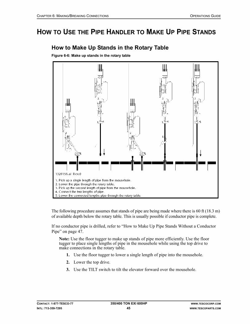
CHAPTER 6: MAKING/BREAKING CONNECTIONS OPERATIONS GUIDE
CONTACT: 1-877-TESCO-77 350/400 TON EXI 600HP WWW.TESCOCORP.COM
INTL: 713-359-7295 45 WWW.TESCOPARTS.COM
HOW TO USE THE PIPE HANDLER TO MAKE UP PIPE STANDS
How to Make Up Stands in the Rotary Table
The following procedure assumes that stands of pipe are being made where there is 60 ft (18.3 m) of available depth below the rotary table. This is usually possible if conductor pipe is complete.
If no conductor pipe is drilled, refer to “How to Make Up Pipe Stands Without a Conductor Pipe” on page 47.
Note: Use the floor tugger to make up stands of pipe more efficiently. Use the floor tugger to place single lengths of pipe in the mousehole while using the top drive to make connections in the rotary table.
1. Use the floor tugger to lower a single length of pipe into the mousehole.
2. Lower the top drive.
3. Use the TILT switch to tilt the elevator forward over the mousehole.
Figure 6-6: Make up stands in the rotary table

OPERATIONS GUIDE CHAPTER 6: MAKING/BREAKING CONNECTIONS
CONTACT: 1-877-TESCO-77 350/400 TON EXI 600HP WWW.TESCOCORP.COM
INTL: 713-359-7295 46 WWW.TESCOPARTS.COM
Caution: Do not use the EXTEND function to move the top drive over the mousehole or the travelling blocks might strike the racking platform if the top drive is being hoisted.
4. Position the elevator on the pipe single.
5. Set the ELEVATOR switch to ‘CLOSE’.
6. Hoist the top drive and the pipe out of the mousehole.
7. Press the FLOAT button. This allows the elevator to come to the vertical position over hole center.
8. Lower the pipe through the rotary table to the required connection height.
9. Set the slips.
10. Set the ELEVATOR switch to ‘OPEN’. Push and hold the SAFETY OPEN button.
11. Use the TILT switch to tilt the elevator back slightly.Note: This prevents the elevator from hitting the tool joint as the top drive is raised.
12. Hoist the top drive until the elevator is clear of the pipe.
13. Set the TILT switch to ‘FORWARD’.
14. Position the elevator over the mousehole.
15. Lower the top drive and close the elevator on the second length of drill pipe now located in the mousehole.
Note: The tugger operator should have place the pipe in the mousehole while the top drive operator was making the connection at the rotary table.
16. Hoist the top drive until the bottom of the second length of pipe is above the pipe in the rotary table.
17. Press the FLOAT button. This allows the elevator to come to hole center.
18. Lower the top drive and stab the pipe in the rotary table.
19. Attach the pipe spinner to the upper length of pipe, or rotate the connection by using chain tongs.
20. Spin the upper pipe until the connection is fully engaged but not tight.
21. Remove the pipe spinner, then use rig tongs to torque the connection to specification.
22. Hoist the top drive and the double length of pipe.
23. Remove the slips.Note: If making up double lengths of pipe only, proceed to “Standard Racking Procedure” on page 75.
24. Lower the top drive and the double length of pipe into the rotary table to the required connection height.
25. Set the slips.
!
CHAPTER 6: MAKING/BREAKING CONNECTIONS OPERATIONS GUIDE
CONTACT: 1-877-TESCO-77 350/400 TON EXI 600HP WWW.TESCOCORP.COM
INTL: 713-359-7295 47 WWW.TESCOPARTS.COM
How to Make Up Pipe Stands Without a Conductor Pipe
If no conductor pipe is in place, make up triple stands of pipe by modifying the previous procedure as follows:
1. Connect the first two single lengths of pipe as described in the previous procedure, then continue to the following steps.
2. Hoist the double stand of pipe until it is above the drill floor.
3. Use the floor tugger to place a single length of pipe into the rotary table.
4. Set the slips.
5. Lower the top drive and the double length of pipe to stab the pipe single in the rotary table.
6. Connect the pipe double and pipe single by using the pipe spinner and rig tongs.
7. Use the rig tongs to torque the connection.
8. Proceed with racking as described in “Standard Racking Procedure” on page 75.

OPERATIONS GUIDE CHAPTER 6: MAKING/BREAKING CONNECTIONS
CONTACT: 1-877-TESCO-77 350/400 TON EXI 600HP WWW.TESCOCORP.COM
INTL: 713-359-7295 48 WWW.TESCOPARTS.COM
How to Make Up Pipe Stands in the Mousehole
It is more difficult and less efficient to make up stands of pipe in the mousehole than when using the rotary table. Use the following procedure when the rotary table is unavailable.
1. Use the floor tugger to lower a single length of pipe into the mousehole.
2. Lower the top drive.
3. Use the TILT switch to tilt the elevator forward over the mousehole.
Warning! Do not use the EXTEND function to move the top drive over the mousehole. If hoisting the top drive while it is extended, it might collide with the racking platform.
Figure 6-7: Make up pipe stands in the mousehole
!

CHAPTER 6: MAKING/BREAKING CONNECTIONS OPERATIONS GUIDE
CONTACT: 1-877-TESCO-77 350/400 TON EXI 600HP WWW.TESCOCORP.COM
INTL: 713-359-7295 49 WWW.TESCOPARTS.COM
4. Position the elevator on the single length of pipe.
5. Set the ELEVATOR switch to ‘CLOSE’.
6. Hoist the pipe out of the mousehole.
7. Use the floor tugger to lower the second length of pipe into the mousehole.
8. Lower the top drive and pipe and stab the second length of pipe that is in the mousehole.
Caution: Release all the weight off the elevator to reduce the friction between the pipe and the elevator.
9. Attach chain tongs to the upper and lower lengths of pipe.
Caution: Most pipe spinners cannot be used when making connections at the mousehole.
10. Ensure the connection is fully engaged but not tightened.
11. Use the rig tongs to torque the pipe connection to the required specification.
12. Hoist the double length of pipe out of the mousehole.
Warning! Adjust the TILT position as required to avoid hitting the racking platform while hoisting the top drive. The same caution applies when using the EXTEND function.
13. Use the floor tugger to lower the third length of pipe into the mousehole.
14. Lower the top drive and double length of pipe to stab the third pipe that is in the mousehole.
Warning! Adjust the TILT position to avoid hitting the racking platform while making this connection.
15. Release all the weight off the elevator to reduce the friction between the pipe and the elevator.
16. Attach chain tongs to the double and single lengths of pipe.
17. Ensure the connection is fully engaged but not tightened.
18. Use the rig tongs to torque the pipe connection to the required specification.
19. Hoist the completed triple stand of pipe until the bottom of the stand is above the floor racking area.
Warning! Use caution when the pipe stand clears the mousehole; the stand will tend to swing to the vertical position. Move the elevator links and elevator to hole centre to avoid hitting the racking platform when hoisting the top drive.
20. Follow the “Standard Racking Procedure” on page 75.
21. Lower the top drive and proceed with making up the next stand of pipe.
!
!
!
!
!

OPERATIONS GUIDE CHAPTER 6: MAKING/BREAKING CONNECTIONS
CONTACT: 1-877-TESCO-77 350/400 TON EXI 600HP WWW.TESCOCORP.COM
INTL: 713-359-7295 50 WWW.TESCOPARTS.COM
HOW TO MAKE UP BHA (COLLARS AND TOOLS)
Use the pipe handler to help make up the Bottom Hole Assembly (BHA), collars, and tools.
Figure 6-8: Connect collars

CHAPTER 6: MAKING/BREAKING CONNECTIONS OPERATIONS GUIDE
CONTACT: 1-877-TESCO-77 350/400 TON EXI 600HP WWW.TESCOCORP.COM
INTL: 713-359-7295 51 WWW.TESCOPARTS.COM
1. Use the floor tugger to put a collar in the mousehole.
2. Ensure that a pick-up sub is installed on the collar.Note: Use chain tongs to install the pick-up sub.
Warning! Torque the connection between the pick-up sub and the collar to prevent it from unscrewing.
3. Raise the grabber box to its maximum height; see procedure for Setting the Grab-ber Height on page 32.
4. Set the TILT switch to ‘FORWARD’.
5. Position the elevators over the mousehole.
6. Lower the top drive and position the elevator on the pick-up sub.
7. Set the ELEVATOR switch to ‘CLOSE’.
8. Hoist the top drive until the collar is clear of the mousehole.
9. Press the FLOAT button. This allows the elevator to return to a vertical position over hole center.
10. Lower the top drive until the collar is correctly positioned in the rotary table.
11. Set the slips and attach a safety clamp.
12. Use the rig tongs to loosen the connection between the pick-up sub and the collar.
13. Once this connection is loosened, use the chain tongs to unscrew the connection completely.
14. Hoist the top drive and the pick-up sub.
15. Use the floor tugger to place a second collar in the mousehole.
16. Set the TILT switch to ‘FORWARD’.
17. Position the elevator over the mousehole.
18. Lower the top drive and the pick-up sub, and stab the second collar that is in the mousehole.
19. Use the chain tongs to connect the pick-up sub and the collar.
20. Hoist the top drive until the collar is clear of the mousehole.
21. Press the FLOAT button. This allows the elevator to move to the vertical position.
22. Lower the top drive to stab the collar that is in the rotary table.
Caution: The elevator links must hang vertically over the connection point.
23. Lower the top drive to position the grabber so that it will close on the pick-up sub, then set the GRABBER switch to ‘CLOSE’.
24. Set the PIPE HANDLER switch to ‘UNLOCK’. This allows the pipe handler to rotate and make up the connection.
25. Set the PIPE HANDLER switch to ‘FWD’ and hold the switch at ‘FWD’ position. The pipe handler begins to rotate at the preset speed.
!
!

OPERATIONS GUIDE CHAPTER 6: MAKING/BREAKING CONNECTIONS
CONTACT: 1-877-TESCO-77 350/400 TON EXI 600HP WWW.TESCOCORP.COM
INTL: 713-359-7295 52 WWW.TESCOPARTS.COM
26. While holding the PIPE HANDLER switch to ‘FWD’, lower the top drive to engage the connection.
Note: Carefully calibrate top drive weight on the connection to prevent the collar from spinning in the elevator. Balance the top drive by raising and lowering it in small increments.
Caution: The grabber override button on the brake handle must be used to hoist the top drive when the grabber is closed.
27. Rotate the connection until it is fully engaged but not tightened.
28. Release the PIPE HANDLER FWD switch.
29. Set grabber switch to ‘OPEN’.
30. Attach rig tongs to the collars.
31. Torque the connection to the required specification.
32. Remove the safety clamp.
33. Hoist the top drive and remove the slips. This suspends the collars from the eleva-tor of the top drive.
34. Lower the collars through the rotary table to the desired connection height.
35. Set the slips and attach a safety clamp.
36. Use the rig tongs to disconnect the pick-up sub from the top collar.
37. Repeat steps 19 to 36 to connect the third collar.
38. When all required collars are made up, do the following:
a. Set the PIPE HANDLER switch to ‘LOCK’.
b. Set the GRABBER switch to ‘OPEN’.
How to Connect Collars Above the Rotary Table
1. Follow steps 1 to 38 of “How to Make Up BHA (Collars and Tools)” on page 50 to connect the first two collars in the rotary table.
Note: When these steps are complete, ensure that:
• there are two collars in the rotary table (one low in the table, the second above),• the top collar is connected to a pick-up sub, and• both collars are suspended from the top drive elevator
2. Remove the safety clamp.
3. Hoist the top drive and remove the slips. This suspends the collars from the top drive elevator.
4. Hoist the top drive and collars above the rotary table.Note: Use the floor tugger to place a third collar in the rotary table. Use the slips and a safety clamp to secure the collar in place.
5. Lower the top drive to stab the connection in the rotary table.
Caution: The elevator links must hang vertically over the connection point.
!
!
CHAPTER 6: MAKING/BREAKING CONNECTIONS OPERATIONS GUIDE
CONTACT: 1-877-TESCO-77 350/400 TON EXI 600HP WWW.TESCOCORP.COM
INTL: 713-359-7295 53 WWW.TESCOPARTS.COM
6. Lower the top drive to position the grabber so that it will close on the pick-up sub, then set the GRABBER switch to ‘CLOSE’.
7. Set the PIPE HANDLER switch to ‘UNLOCK’. This allows the pipe handler to rotate and make-up the connection.
8. Set the PIPE HANDLER switch to ‘FWD’ and hold it at ‘FWD’ position. The pipe handler will begin to rotate at the preset speed.
9. While holding the PIPE HANDLER FWD switch lower the top drive to engage the connection.
Note: Carefully calibrate top drive weight on the connection to prevent the collar from spinning in the elevator. Balance the top drive by raising and lowering it in small increments.
Caution: The grabber override button on the brake handle must be used to hoist the top drive when the grabber is closed.
10. Rotate the connection until it is fully engaged but not tightened.
11. Set the grabber switch to ‘OPEN’.
12. Attach rig tongs to the collars.
13. Torque the connection to the required specification for the drill collar.
14. Remove the safety clamp.
15. Hoist the top drive to clear the collars from the rotary table.
16. Rack the collars according to the “Standard Racking Procedure” on page 75.
17. When all required collars are picked up, do the following:
a. Set the PIPE HANDLER switch to ‘LOCK’.
b. Set the GRABBER switch to ‘OPEN’.
!

OPERATIONS GUIDE CHAPTER 6: MAKING/BREAKING CONNECTIONS
CONTACT: 1-877-TESCO-77 350/400 TON EXI 600HP WWW.TESCOCORP.COM
INTL: 713-359-7295 54 WWW.TESCOPARTS.COM
This page has been left blank intentionally.

CHAPTER 7: DRILLING OPERATIONS OPERATIONS GUIDE
CONTACT: 1-877-TESCO-77 350/400 TON EXI 600HP WWW.TESCOCORP.COM
INTL: 713-359-7295 55 WWW.TESCOPARTS.COM
CHAPTER 7: DRILLING OPERATIONS
WELL CONTROL
As the owner/operator of a top drive, guidelines and procedures must be established for all possible well control situations. These guidelines and procedures should reflect industry standard practice for operating location and conditions.
In most cases, the addition of a top drive will not significantly change the established proce-dures for well control. Whenever possible, use the same well control procedures established prior to the addition of a top drive.
All personnel must be trained to adhere to safe operating practices and should be periodically tested to verify their skill level.
Review safety procedures before each drilling operation.
SURFACE HOLE DRILLING OPERATIONS
The following procedure applies when drilling a surface hole with drill collars, by using either a single joint of drill pipe (as a working pipe single) or drillable pick-up subs.
Use only drillable pick-up subs for tripping operations. A drillable pick-up sub has a 5 ft (1.5 m) length of tube on which the elevators can slide up and down. The threaded connections at the top of the drillable pick-up sub are the same as those on the saver sub, while those at the bot-tom of the drillable pick-up sub are the same as those on the drill collars. This allows the drill-able pick-up sub to be threaded into drill collars and used as a pick-up sub for racking operations. A drillable pick-up provides the ability to ream and back-ream during tripping operations, if required.
How to Drill a Surface Hole
1. Use the appropriate rig equipment and safe working procedures to position a collar in the mousehole.
2. Use chain tongs to install a drillable pick-up sub on the collar.
Caution: Torque the connection between the drillable pick-up sub and the collar to prevent it from unscrewing.!
OPERATIONS GUIDE CHAPTER 7: DRILLING OPERATIONS
CONTACT: 1-877-TESCO-77 350/400 TON EXI 600HP WWW.TESCOCORP.COM
INTL: 713-359-7295 56 WWW.TESCOPARTS.COM
3. Lower the top drive to position the elevator at the pick-up sub.
4. Set the ELEVATOR switch to ‘CLOSE’.
5. Hoist the top drive until the drillable pick-up sub and collar clear the mousehole.
6. Press the FLOAT button. This will bring the elevator to the vertical position.Note: Ensure there is adequate clearance for the racking platform.
7. Install the bit sub and drill bit, and apply the appropriate torque.
8. Hoist the collar out of the bit-breaker and lower it through the rotary table.
9. When the bit reaches the bottom of the hole, hoist it 1 to 2 ft (0.3 to 0.6 m) off the bottom and set the slips.
10. Lower the top drive with the elevator closed. Allow the elevator to slide down the drillable pick-up sub. Guide the drillable pick-up sub through the pipe guide.
11. Set the MODE switch to ‘CONN’.
12. Set the QUILL switch to ‘FWD’.
13. Slowly lower the top drive to engage the connection between the saver sub and the drillable pick-up sub.
Warning! Ensure the rotary table is locked.
14. Lead the top drive into the connection.
15. When the connection is fully engaged, set the QUILL switch to neutral.
16. Set the GRABBER switch to ‘CLOSE’.
17. Set the QUILL switch to ‘FWD’ (the MODE switch should still be set to ‘CONN’).
18. When the torque reaches the desired torque value, turn the QUILL switch to neutral.
19. Set the GRABBER switch to ‘OPEN’.
20. Hoist the top drive and remove the slips.
21. Set the mudsaver VALVE switch to ‘OPEN’.
22. Start the rig mud pump.
23. Begin drilling.
About Connections and Surface Hole Operations
Make connections as per normal procedure. Leave the drillable pick-up sub on the top drive. Refer to “How to Make Up BHA (Collars and Tools)” on page 50.
About Tripping and Surface Hole Operations
Trip drill pipe in and out of the hole, but use a drillable pick-up sub on the top of each stand instead of a standard pick-up sub.
!
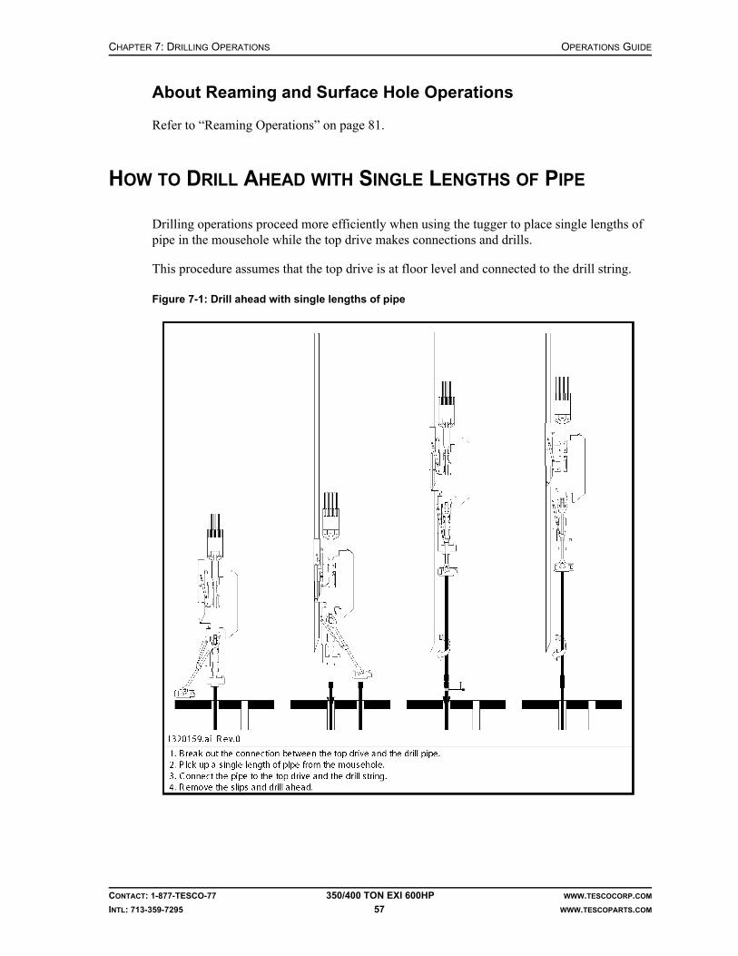
CHAPTER 7: DRILLING OPERATIONS OPERATIONS GUIDE
CONTACT: 1-877-TESCO-77 350/400 TON EXI 600HP WWW.TESCOCORP.COM
INTL: 713-359-7295 57 WWW.TESCOPARTS.COM
About Reaming and Surface Hole Operations
Refer to “Reaming Operations” on page 81.
HOW TO DRILL AHEAD WITH SINGLE LENGTHS OF PIPE
Drilling operations proceed more efficiently when using the tugger to place single lengths of pipe in the mousehole while the top drive makes connections and drills.
This procedure assumes that the top drive is at floor level and connected to the drill string.
Figure 7-1: Drill ahead with single lengths of pipe

OPERATIONS GUIDE CHAPTER 7: DRILLING OPERATIONS
CONTACT: 1-877-TESCO-77 350/400 TON EXI 600HP WWW.TESCOCORP.COM
INTL: 713-359-7295 58 WWW.TESCOPARTS.COM
1. Raise the bit 1 to 2 ft (0.3 to 0.6 m) off the bottom of the hole.
2. Set the QUILL switch to neutral.
3. Allow the reactive torque to release.
Caution: As the torque releases, the drill string may rotate slightly. Wait until the rotation ceases before continuing.
4. Set the slips.
5. Shut off the rig mud pump.
6. Monitor the standpipe pressure gauge and wait for the mud pump pressure to decrease to zero.
7. Set the mudsaver VALVE switch to ‘CLOSE’.
8. Position the grabber so that it will close on the box of the drill pipe.
9. Set the GRABBER switch to ‘CLOSE’.
Warning! Do not close the grabber on the saver sub or the hard band of the drill pipe.
10. Set the MODE switch to ‘CONN’.
11. Set the QUILL switch to ‘REV’.Note: The top drive torque will increase to the preset value.
12. Press and hold the BREAKOUT button.Note: Torque increases until it reaches the maximum value available for breakout torque for the unit.
13. When the quill rotates 1/2 turn, release the BREAKOUT button.
14. Immediately set the GRABBER switch to ‘OPEN’.Note: This raises the top drive in small increments and minimizes the load on the threads as the connection unscrews. The counter-balance system also assists with thread disengagement.
15. Lead the top drive out of the drill pipe connection.Note: To avoid damaging the pipe threads, do not let the weight of the top drive rest on the connection while it unscrews.
16. When the connection unscrews completely, set the QUILL switch to neutral.
17. Hoist the top drive until the elevator clears the drill string stump in the rotary table.
18. Set the ELEVATOR switch to ‘OPEN’, then push and hold the elevator SAFETY OPEN button.
19. Use the TILT switch to move the elevator forward so that it is above the mousehole.
20. Lower the top drive until the elevator reaches the drill pipe in the mousehole.
21. Position the elevator on the drill pipe, then set the ELEVATOR switch to ‘CLOSE’.
22. Hoist the top drive until the single length of pipe is above the drill pipe stump in the rotary table.
23. Press the FLOAT button to bring the elevator to the vertical position.
!
!

CHAPTER 7: DRILLING OPERATIONS OPERATIONS GUIDE
CONTACT: 1-877-TESCO-77 350/400 TON EXI 600HP WWW.TESCOCORP.COM
INTL: 713-359-7295 59 WWW.TESCOPARTS.COM
Caution: Rig floor personnel should stabilize the lower end of the drill pipe.
24. Lower the top drive and stab the drill pipe connection.
25. Position a back-up tong on the box connection of the stump.
26. Set the MODE switch to ‘CONN’.
27. Set the QUILL switch to ‘FWD’.
28. Use the TORQUE switch to increase torque to 30 to 40% of the maximum connect value required for the thread and connection type.
Note: Torque values are set prior to start of the drilling operation and these values are entered at the driller's panel using the procedure defined in “How to Set or Change Drive Parameters” on page 26.
29. Lower the top drive further until the pipe makes contact with the saver sub.
30. Use the TILT function to guide the pipe through the drill pipe guide.
31. Lead the top drive into the connection until the pipe/pipe and pipe/saver sub con-nections are fully engaged but not tightened.
Note: When both connections are fully engaged, the break-out tongs will tighten and the top drive will stall.
32. Use the TORQUE switch to increase the torque value to the make up value required for the thread and connection type.
33. Wait until the torque increases to the required make up torque for the connection.
34. Set the QUILL switch to neutral.
35. Remove the break-out tong.
36. Set the ELEVATOR switch to ‘OPEN’, and press and hold the ELEVATOR SAFETY OPEN button.
37. Set the TILT switch to ‘BACK’. This moves the elevator away from the drill string and avoids unnecessary wear of the elevator inserts. Avoid contacting the elevator to the torque track.
38. Set the VALVE switch to ‘OPEN’.
39. If required, start the rig mud pump.
40. Hoist the top drive and drill string.
41. Remove the slips.
42. Set the MODE switch to ‘DRILL’.
43. Set the QUILL switch to ‘FWD’.
44. Use the SPEED switch to set the required drilling rpm.
45. Use the TORQUE switch to increase the torque to the desired drilling torque value for the thread and connection type.
Note: Torque values are set prior to start of the drilling operation and these values are entered at the driller's panel using the procedure defined in “How to Set or Change Drive Parameters” on page 26. The preset value for the maximum drilling torque must be less than the maximum torque value for the connection type.
46. Commence drilling.
!

OPERATIONS GUIDE CHAPTER 7: DRILLING OPERATIONS
CONTACT: 1-877-TESCO-77 350/400 TON EXI 600HP WWW.TESCOCORP.COM
INTL: 713-359-7295 60 WWW.TESCOPARTS.COM
HOW TO DRILL AHEAD WITH PIPE STANDS
This procedure assumes that the top drive is at floor level and connected to the drill string.
Figure 7-2: Drill ahead with pipe stands

CHAPTER 7: DRILLING OPERATIONS OPERATIONS GUIDE
CONTACT: 1-877-TESCO-77 350/400 TON EXI 600HP WWW.TESCOCORP.COM
INTL: 713-359-7295 61 WWW.TESCOPARTS.COM
1. Raise the bit 1 to 2 ft (0.3 to 0.6 m) off the bottom of the hole.
2. Set the QUILL switch to neutral.
3. Allow the reactive torque to release.
Caution: As the torque releases, the drill string may rotate slightly. Wait until the rotation ceases before continuing.
4. Set the slips.
5. Shut off the rig mud pump.
6. Monitor the standpipe pressure gauge and wait for the mud pump pressure to decrease to zero.
7. Set the mudsaver VALVE switch to ‘CLOSE’.
8. Position the grabber so that it will close on the box of the drill pipe.
9. Set the GRABBER switch to ‘CLOSE’.
Warning! Do not close the grabber on the saver sub or the hard band of the drill pipe.
10. Set the MODE switch to ‘CONN’.
11. Set the QUILL switch to ‘REV’.Note: The top drive torque will increase to the preset value.
12. Press and hold the BREAKOUT button.Note: Torque increases until it reaches the maximum value available for breakout torque for the unit.
13. When the quill rotates 1/2 turn, release the BREAKOUT button.
14. Immediately set the GRABBER switch to ‘OPEN’.Note: This raises the top drive in small increments and minimizes the load on the threads as the connection unscrews. The counter-balance system also assists with thread disengagement.
15. Lead the top drive out of the drill pipe connection.Note: To avoid damaging the pipe threads, do not let the weight of the top drive rest on the connection while it unscrews.
16. When the connection unscrews completely, set the QUILL switch to neutral.
17. Hoist the top drive until the elevator clears the drill string stump in the rotary table.
18. Set the ELEVATOR switch to ‘OPEN’, then push and hold the ELEVATOR SAFETY OPEN button.
19. Use the TILT switch to move the elevator forward so that it is past the stump.
20. Hoist the top drive to the racking platform.
21. Position the elevator to capture the top tool joint of the next stand of pipe.
22. Set the ELEVATOR switch to ‘CLOSE’.
23. Ensure that rig floor personnel are ready to assist in guiding the stand out of its racking position.
24. When the stand is picked up, press the FLOAT button.
!
!

OPERATIONS GUIDE CHAPTER 7: DRILLING OPERATIONS
CONTACT: 1-877-TESCO-77 350/400 TON EXI 600HP WWW.TESCOCORP.COM
INTL: 713-359-7295 62 WWW.TESCOPARTS.COM
25. Hoist the top drive slowly, allowing the rig floor personnel to guide the bottom of the stand to a vertical position.
26. Hoist the top drive until the bottom pin of the stand clears the stump.
27. Lower the top drive and stab the drill pipe connection into the stump.
28. Position a back-up tong on the box connection of the stump.
29. Lower the top drive further until the pipe makes contact with the saver sub.
30. Set the MODE switch to ‘CONN’.
31. Set the QUILL switch to ‘FWD’.
32. Use the TORQUE switch to increase torque to 30 to 40% of the maximum connect value required for the thread and connection type.
Note: Torque values are set prior to start of the drilling operation and these values are entered at the driller's panel using the procedure defined in “How to Set or Change Drive Parameters” on page 26.
33. Use the TILT function to guide the pipe through the drill pipe guide.
34. Lead the top drive into the connection until the pipe/pipe and pipe/saver sub connections are fully engaged but not tightened.
Note: When both connections are fully engaged, the break-out tongs will tighten and the top drive will stall.
35. Use the TORQUE switch to increase the torque value to the make up value required for the thread and connection type.
36. Wait until the torque increases to the required make up torque for the connection.
37. Set the QUILL switch to neutral.
38. Remove the break-out tong.
39. Set the ELEVATOR switch to ‘OPEN’, and press and hold the ELEVATOR SAFETY OPEN button.
40. Set the TILT switch to ‘BACK’. This moves the elevator away from the drill string and avoids unnecessary wear of the elevator inserts. Avoid contacting ele-vator to torque track.
41. Set the VALVE switch to ‘OPEN’.
42. If required, start the rig mud pump.
43. Hoist the top drive and drill string.
44. Remove the slips.
45. Set the MODE switch to ‘DRILL’.
46. Set the QUILL switch to ‘FWD’.
47. Use the SPEED switch to set the required drilling rpm.
48. Use the TORQUE switch to increase the torque to the desired drilling torque value for the thread and connection type.
Note: Torque values are set prior to start of the drilling operation and these values are entered at the driller's panel using the procedure defined in “How to Set or Change Drive Parameters” on page 26. The preset value for the maximum drilling torque must be less than the maximum torque value for the connection type.
49. Commence drilling.

CHAPTER 7: DRILLING OPERATIONS OPERATIONS GUIDE
CONTACT: 1-877-TESCO-77 350/400 TON EXI 600HP WWW.TESCOCORP.COM
INTL: 713-359-7295 63 WWW.TESCOPARTS.COM
SLIDE DRILLING OPERATIONS
Introduction
In slide drilling operations, power to the bit is supplied using downhole mud motors. As a result, the drill string does not rotate during drilling operations. This procedure addresses how to make and break connections during slide drilling operations.
Caution: During slide drilling operations, ensure the grabber remains closed on the saver sub. Once the grabber is fully closed, return the GRABBER switch to the neutral position to avoid over-heating the auxiliary hydraulic system.
During extended periods of slide drilling, set the GRABBER switch to ‘CLOSE’, then back to neutral, once every hour. This helps to maintain full pressure in the grabber–close hydraulic circuit.
Mud Motors in Slide Drilling Operations
When drilling with a downhole mud motor, ensure the top drive drill–forward torque setting is greater than the maximum torque output of the mud motor. See also “Combination Drilling Operations” on page 68 for more information.
1. Trip in the drill pipe and mud motor until the mud motor reaches the bottom of the hole. Refer to “Tripping Operations” on page 69.
2. Connect the top drive to the drill string by lowering the top drive until the drill pipe makes contact with the saver sub.
Note: Use the TILT feature to guide the drill pipe into the drill pipe guide.
3. Use the grabber lift needle valves to position the grabber on the box of the drill pipe.
4. Set the GRABBER switch to ‘CLOSE’.
5. Set the MODE switch to ‘CONN’.
6. Set the QUILL switch to ‘FWD’.
7. Lead the top drive into the connection until the pipe/saver sub connection is fully engaged but not tightened.
8. Use the TORQUE switch to increase torque to the maximum ‘connect’ value required for the thread and connection type.
Note: Torque values are set prior to start of the drilling operation and these values are entered at the driller’s panel using the procedure defined in “How to Set or Change Drive Parameters” on page 26.
9. Wait until the torque increases to the required value for the current thread and con-nection type.
10. As soon as the torque reaches the required value to make up the connection, set the QUILL switch to neutral.
11. Set the GRABBER switch to ‘OPEN’.
12. Use the grabber lift needle valves to reposition the grabber on the saver sub.
!

OPERATIONS GUIDE CHAPTER 7: DRILLING OPERATIONS
CONTACT: 1-877-TESCO-77 350/400 TON EXI 600HP WWW.TESCOCORP.COM
INTL: 713-359-7295 64 WWW.TESCOPARTS.COM
13. Set the GRABBER switch to ‘CLOSE’.
14. Set the VALVE switch to ‘OPEN’.
15. Start the rig mud pump.
16. Hoist the top drive and drill string.
17. Remove the slips.
18. Start drilling by lowering the top drive.
The orientation of the tool face may need to be adjusted to drill in the required direction when drilling with a mud motor. Refer to the next section, “How to Adjust the Tool Face Orientation”.
How to Adjust the Tool Face Orientation
This procedure assumes the following:
• the top drive is above the drill floor• the top drive is connected to the drill string• the top drive is ready to proceed with drilling• the grabber is closed on the saver sub
1. Set the MODE switch to ‘DRILL’.
2. Set the QUILL switch to ‘FWD’.
3. Use the SPEED switch to set the speed to 2 rpm.
4. Use the TORQUE switch to increase the torque gradually. Monitor the output on the DELIVERED TORQUE meter.
5. When observing deflection of the grabber box, set the GRABBER switch to ‘OPEN’.
Note: If the torque in the drill string matches the torque of the top drive, open the grabber with no rotation (static).
6. Reorient the tool face by doing one of the following:
a. To turn the drill string clockwise, use the TORQUE switch to increase the torque slowly. Increasing the torque allows the top drive to overcome the reactive torque of the downhole motor. When this happens, the drill string slowly turns clockwise.
Note: When the required tool face orientation is achieved, slowly decrease the torque until the quill stalls, then close the grabber.
b. To turn the drill string counter-clockwise, use the TORQUE switch to decrease the torque slowly. Decreasing the torque allows the downhole motor to overcome the torque of the top drive, and the drill string turns slowly counter-clockwise.
Note: When the required tool face orientation is achieved, slowly increase the torque until the quill stalls, then close the grabber.
7. Commence drilling.

CHAPTER 7: DRILLING OPERATIONS OPERATIONS GUIDE
CONTACT: 1-877-TESCO-77 350/400 TON EXI 600HP WWW.TESCOCORP.COM
INTL: 713-359-7295 65 WWW.TESCOPARTS.COM
How to Make and Break Connections During Slide Drilling Operations
1. Set the slips.
Caution: Ensure the rotary table is locked.
2. Set the GRABBER switch to ‘OPEN’.
3. Use the grabber lift needle valves to reposition the grabber on the box of the drill pipe.
4. Set the GRABBER switch to ‘CLOSE’.
5. Shut off the rig mud pump.
6. Monitor the standpipe pressure gauge and wait for the mud pump pressure to decrease to zero.
7. Set the mudsaver VALVE switch to ‘CLOSE’.
8. Set the MODE switch to ‘CONN’.
9. Set the QUILL switch to ‘REV’.Note: The top drive torque will increase to the preset value.
10. Press and hold the BREAKOUT button.Note: Torque increases until it reaches the maximum value available for breakout torque for the unit.
11. When the saver sub/pipe connection breaks and rotates 1/2 turn, release the BREAKOUT button.
12. Immediately set the GRABBER switch to ‘OPEN’.Note: This raises the top drive in small increments and minimizes the load on the threads as the connection unscrews.
13. Lead the top drive out of the drill pipe connection.Note: To avoid damaging the pipe threads, do not let the weight of the top drive rest on the connection while it unscrews.
14. When the connection unscrews completely, set the QUILL switch to neutral.
15. Hoist the top drive high enough to allow the elevator to pass over the stump.
16. Use the top drive elevator to pick up the required drill pipe.Note: Slide drill with either single lengths of pipe or stands of pipe. Refer to “How to Drill Ahead with Single Lengths of Pipe” on page 57 and “How to Drill Ahead with Pipe Stands” on page 60 for more information.
17. Hoist the top drive until the bottom pin of the pipe stand clears the stump.
18. Press the FLOAT button.The elevator and pipe stand will move to hole center.
19. Position the break-out tong on the box connection of the stump.
20. Lower the top drive until the drill pipe makes contact with the saver sub.Note: Use the TILT function to guide the drill pipe into the drill pipe guide.
21. Set the MODE switch to ‘CONN’.
22. Set the QUILL switch to ‘FWD’.
!
OPERATIONS GUIDE CHAPTER 7: DRILLING OPERATIONS
CONTACT: 1-877-TESCO-77 350/400 TON EXI 600HP WWW.TESCOCORP.COM
INTL: 713-359-7295 66 WWW.TESCOPARTS.COM
23. Use the TORQUE switch to increase torque to 30 to 40% of the maximum connect value required for the thread and connection type.
Note: Torque values are set prior to start of the drilling operation and these values are entered at the driller's panel using the procedure defined in “How to Set or Change Drive Parameters” on page 26.
24. Lead the top drive into the connection until the pipe/pipe and pipe/saver sub connections are fully engaged but not tightened.
Note: When both connections are fully engaged, the break-out tongs will tighten and the top drive will stall. It is also possible that the top drive will torque into the locked rotary table.
25. Use the TORQUE switch to increase the torque to the maximum connect value required for the thread and connection type.
26. Wait until the DELVERED TORQUE gauge increases to required value for the connection type.
27. As soon as the torque reaches the required value to make up connections, set the QUILL switch to neutral.
28. Remove the break-out tong.
29. Use the grabber lift needle valves to reposition the grabber on the saver sub (the grabber should be open).
30. Set the GRABBER switch to ‘CLOSE’.
31. Set the mudsaver VALVE switch to open.
32. Start the rig mud pump.
33. Hoist the top drive and drill pipe.
34. Remove the slips.
Danger! Exercise caution when removing the slips. Stored drill string torque may spin the slips when the drill string is hoisted.
35. Commence drilling.
!

CHAPTER 7: DRILLING OPERATIONS OPERATIONS GUIDE
CONTACT: 1-877-TESCO-77 350/400 TON EXI 600HP WWW.TESCOCORP.COM
INTL: 713-359-7295 67 WWW.TESCOPARTS.COM
How to Maintain the Tool Face Orientation During Slide Drilling Operations
It is essential to maintain the tool orientation during slide drilling, as it determines the drilling direction. To maintain tool orientation while making or breaking connections, the drill string must be locked in the rotary table with the slips, as described in “How to Make and Break Connections During Slide Drilling Operations” on page 65.
Caution: The rotary table must remain locked during this procedure.
TESCO recommends marking the position of the drill string to monitor whether or not some of the stored torque in the drill string is released when making a connection.
In some instances it might be necessary to remove the slips while the grabber is still open. In this case, the top drive must absorb the torque in the drill string. Use the following procedure to allow the top drive to safely absorb the torque in the drill string.
1. Set the MODE switch to ‘DRILL’.
2. Set the QUILL switch to ‘FWD’.
3. Use the SPEED switch to set the quill speed to 4 to 5 rpm.
4. Use the TORQUE switch to set the torque value of the top drive to match the torque in the drill string. Refer to the following procedure, “How to Record the Drill String Torque”, for more information.
5. When the torque reaches the required value, hoist the top drive and remove the slips.
How to Record the Drill String Torque
This procedure assumes that a mud motor is currently being used for drilling, and the bit is currently on the bottom of the wellbore.
1. Close the grabber on the saver sub.
2. Set the MODE switch to ‘DRILL’.
3. Set the QUILL switch to ‘FWD’.
4. Use the SPEED switch to set the speed to 2 rpm.
5. Use the TORQUE switch to increase the torque gradually. Monitor the DELIVERED TORQUE meter.
6. When observing deflection of the grabber box towards the driller’s side (clockwise), record the torque value.
7. Re-check the drill string torque periodically during downhole motor operations.
!

OPERATIONS GUIDE CHAPTER 7: DRILLING OPERATIONS
CONTACT: 1-877-TESCO-77 350/400 TON EXI 600HP WWW.TESCOCORP.COM
INTL: 713-359-7295 68 WWW.TESCOPARTS.COM
COMBINATION DRILLING OPERATIONS
Summary
Combination drilling refers to the practice of rotating the top drive slowly in forward rotation while drilling with a downhole mud motor. This practice, if used, usually occurs after the angle is built and it is only necessary to maintain the achieved angle.
Caution: It is essential to use the following guideline when drilling using this method.
The SET torque output reading on the driller’s panel must AT ALL TIMES be 20% higher than the maximum torque output of the downhole motor in use.
Explanation
Failure to maintain the top drive torque setting at a sufficient level to counteract the downhole motor torque can force the top drive into a partial or continuous state of unwind. If the top drive torque is set too low, the downhole motor can apply reactive torque to the top drive and cause it to rotate in reverse (counter-clockwise). The power generated by the top drive rotating in reverse is dissipated by the controlled unwind program called ‘regen-mode’. Extended use of this mode while power is still applied to the mud motor will eventually create a situation where the resistive brake might overheat and/or an overvoltage condition occurs that can dis-able the drive.
Danger! If the drive shuts down under these conditions, a complete uncontrolled unwind of the top drive can occur. This event can cause severe damage to the drive system.
!
!

CHAPTER 8: TRIPPING OPERATIONS OPERATIONS GUIDE
CONTACT: 1-877-TESCO-77 350/400 TON EXI 600HP WWW.TESCOCORP.COM
INTL: 713-359-7295 69 WWW.TESCOPARTS.COM
CHAPTER 8: TRIPPING OPERATIONS
• Trip Out: the act of removing the drill string from the wellbore.• Trip In: the act of inserting the drill string into the wellbore.
WELL CONTROL DURING TRIPPING OPERATIONS
As the owner/operator of a top drive, guidelines and procedures must be established for all possible well control situations. These guidelines and procedures should reflect industry standard practice for operating location and conditions.
In most cases, the addition of a top drive will not significantly change the established well con-trol procedures. Whenever possible, use the same well control procedures established prior to the addition of a top drive.
All personnel must be trained to adhere to safe operating practices and should be periodically tested to verify their skill level.
Safety procedures should be reviewed before each operation.
Caution: If the top drive is connected to the drill string when the drill string is off the bottom of the hole, the following equipment is required: · additional saver sub· spare double-ball mudsaver valve· strip kit (tools required to remove mudsaver actuator)
If planning to connect the top drive to the drill string when it is off the bottom of the hole, TESCO recommends removing the actuator and servicing the entire assembly on a regular basis. Refer to the following procedure for information on how to remove the actuator.
!

OPERATIONS GUIDE CHAPTER 8: TRIPPING OPERATIONS
CONTACT: 1-877-TESCO-77 350/400 TON EXI 600HP WWW.TESCOCORP.COM
INTL: 713-359-7295 70 WWW.TESCOPARTS.COM
How to Remove the Mudsaver Valve Actuator During Well Control Tripping
Danger! The removal of the actuator off of the double ball valve is relatively simple and quick, however, there are a few steps that must be followed in sequence for reasons of safety.
1. Set the slips.
2. Shut off the mud pump.
3. Use the valve wrench that is provided to close the manual ball valve. This ball valve is located below the actuator. See Figure 8-1 on page 71.
4. Set the mudsaver VALVE switch (driller’s panel) to ‘OPEN’. This will open the actuated mudsaver valve.
Note: Visually verify that there is no pressure in the standpipe at this point.
5. Remove the upper die-lock clamp from the mudsaver valve.
6. Remove the lower die-lock clamp from the mudsaver valve.
7. Use the grabber lift needle valves to position the grabber so that it will close on the bottom of the mudsaver valve.
8. Set the GRABBER switch (driller’s panel) to ‘CLOSE’. The grabber should close on the mudsaver valve.
9. Break out the mudsaver valve from the top drive.
a. Set the MODE switch to ‘CONN’. Set the QUILL switch to ‘REV’.
b. Push and hold the BREAKOUT button. Release the BREAKOUT button when the quill has rotated 1/2 turn.
10. Immediately set the GRABBER switch to ‘OPEN’.Note: Hoist the top drive in small increments as the connection unscrews. This will keep the weight of the top drive off the connection.
11. Hoist the top drive until the grabber is positioned approximately 1 in. from the actuator.
Caution: Do not hoist any higher, or the grabber will hit the actua-tor. This can damage the actuator.
12. Use the grabber lift needle valve to lift the grabber until the actuator rests on the grabber.
13. Remove the two worm ring clamps from the actuator.
14. Remove the two snap rings and the two hex drives. Use a slide hammer to remove these items. See Figure 8-2 on page 72.
15. Remove the four upper lock pin assemblies.Note: The lock pin assemblies consist of a setscrew, a spring and a lock pin.
16. Remove the four lower lock pin assemblies if they are present.
17. Install two lifting eyes in the upper lock pin holes at 180°. Attach a tugger or other lifting device to the lifting eyes.
!
!

CHAPTER 8: TRIPPING OPERATIONS OPERATIONS GUIDE
CONTACT: 1-877-TESCO-77 350/400 TON EXI 600HP WWW.TESCOCORP.COM
INTL: 713-359-7295 71 WWW.TESCOPARTS.COM
18. Hoist the top drive slowly. The actuator should slide off of the mudsaver valve. Use the tugger or lifting device to remove the actuator from the grabber after the actuator is released from the mudsaver valve.
19. An inside Blow Out Preventer or other device can be installed to control the well pressure at this stage.
20. The top drive may be used to make up the connection.
21. After the connection is secure, use the mudsaver valve wrench to open the manual ball valve slowly.
22. The drill string can now be inserted into the wellbore. Use the procedure described in “How to Trip In Drill Pipe” on page 80.
Figure 8-1: Remove the mudsaver valve actuator for well control

OPERATIONS GUIDE CHAPTER 8: TRIPPING OPERATIONS
CONTACT: 1-877-TESCO-77 350/400 TON EXI 600HP WWW.TESCOCORP.COM
INTL: 713-359-7295 72 WWW.TESCOPARTS.COM
TRIP OUT OPERATIONS
Before beginning trip out operations, observe all required operating conventions. These would include procedures such as ‘circulating the hole,’ ‘pumping a pill,’ etc.
Figure 8-2: Remove the actuator from the mudsaver valve
1. Pin2. Spring3. Set Screw4. Hex Drive Shaft

CHAPTER 8: TRIPPING OPERATIONS OPERATIONS GUIDE
CONTACT: 1-877-TESCO-77 350/400 TON EXI 600HP WWW.TESCOCORP.COM
INTL: 713-359-7295 73 WWW.TESCOPARTS.COM
How to Trip Out Drill PipeFigure 8-3: Trip out drill pipe

OPERATIONS GUIDE CHAPTER 8: TRIPPING OPERATIONS
CONTACT: 1-877-TESCO-77 350/400 TON EXI 600HP WWW.TESCOCORP.COM
INTL: 713-359-7295 74 WWW.TESCOPARTS.COM
Caution: Ensure that the pipe handler is oriented such that the links can be tilted toward the derrickman when the drill pipe is ready to be racked.
1. Shut off the rig mud pumps.
2. Monitor the standpipe gauge to ensure that mud pump pressure decreases to zero.
3. Set the VALVE switch to ‘CLOSE’.
4. Hoist the top drive.
5. Set the slips.Note: Ensure the stored torque in the drill string has dissipated before the slips are set.
6. Position the elevator on the drill pipe using the TILT function.
7. Set the ELEVATOR switch to ‘CLOSE’.
8. Hoist or lower the top drive until the grabber is positioned on the tool joint of the drill pipe.
9. Set the GRABBER switch to ‘CLOSE’.
10. Set the MODE switch to ‘CONN’.
11. Set the QUILL switch to ‘REV’.Note: The top drive torque will increase to the preset torque value for reverse rotation.
12. Press and hold the BREAKOUT button.Note: The top drive torque will increase to the break out torque value for the unit.
13. When the connection loosens and the quill rotates 1/2 turn, release the BREAKOUT button.
14. Immediately set the GRABBER switch to ‘OPEN’.Note: This raises the top drive in small increments as the connection unscrews.
15. Lead the top drive out of the drill pipe connection.Note: To avoid damaging the pipe threads, do not allow the weight of the top drive to sit on the connection while it unscrews.
16. When the top drive clears the connection, set the QUILL switch to neutral.
17. Hoist the top drive and drill pipe.
18. Remove the slips.
19. Hoist the top drive to lift the drill pipe (single, double or stand) above the rotary table.
20. Set the slips.
21. Use tongs to break the stump connection, then unscrew the connection by using chain tongs or a pipe spinner.
22. Hoist the drill pipe clear of the stump.
23. Proceed with the standard racking procedure. See “Standard Racking Procedure” on page 75.
24. Lower the top drive and grab the drill string stump with the elevator.
25. Repeat steps 17 to 24 to trip out the rest of the drill string.
!

CHAPTER 8: TRIPPING OPERATIONS OPERATIONS GUIDE
CONTACT: 1-877-TESCO-77 350/400 TON EXI 600HP WWW.TESCOCORP.COM
INTL: 713-359-7295 75 WWW.TESCOPARTS.COM
Standard Racking Procedure
1. Hoist the drill pipe (single, double or triple stand) until the bottom is above the floor racking area.
Note: Elevator links will have to be set to vertical/hole center to avoid hitting the racking board.
2. Set the TILT switch to ‘FWD’.
3. Allow the rig floor personnel to push the bottom of the stand into place on the racking floor.
4. Set the stand down in the racking area.
5. Position the tip of the stand where the derrickman can easily reach and take control of it.
6. Wait until the stand is secured and the derrickman is ready to take control of the stand.
7. Push and hold the ELEVATOR SAFETY OPEN button.
8. Set the ELEVATOR switch to ‘OPEN’.
9. Press the FLOAT button.
10. Lower the top drive to receive the next section of pipe.
Caution: In cold weather operations mud can freeze within the com-ponents. To prevent freezing, air blow the top drive, kelly hose and stand pipe back to tank after pulling 4-5 stands of free pipe and when stopping for a flow check. If the mud valve is to be closed for any length of time in extreme weather conditions, the same proce-dures apply.
How to Trip Out BHA (Collars and Tools)
This procedure assumes that all drill pipe has been removed from the wellbore and that the first collar is above the rotary table.
Note: Ensure that the pipe handler is oriented such that the links can be tilted toward the derrickman when the collars are ready to be racked.
!
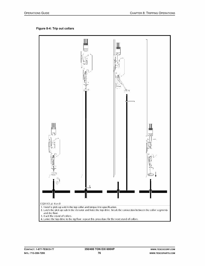
OPERATIONS GUIDE CHAPTER 8: TRIPPING OPERATIONS
CONTACT: 1-877-TESCO-77 350/400 TON EXI 600HP WWW.TESCOCORP.COM
INTL: 713-359-7295 76 WWW.TESCOPARTS.COM
Figure 8-4: Trip out collars

CHAPTER 8: TRIPPING OPERATIONS OPERATIONS GUIDE
CONTACT: 1-877-TESCO-77 350/400 TON EXI 600HP WWW.TESCOCORP.COM
INTL: 713-359-7295 77 WWW.TESCOPARTS.COM
1. Set the slips.
2. Attach a safety clamp.
3. Ensure that the elevator and elevator links are hanging vertically.
4. Set the PIPE HANDLER switch to ‘UNLOCK’.
5. Set and hold the PIPE HANDLER switch at FWD position.Note: The pipe handler will begin to rotate at the preset speed.
6. Position the pipe handler so that the TILT feature can be used to assist in racking the collars.
7. When the pipe handler is in the proper position, release the PIPE HANDLER switch from ‘FWD’ to neutral position.
8. Set the PIPE HANDLER switch to ‘LOCK’.
9. Use the TILT feature to position the top drive elevator to accept a pick-up sub.
10. Set the ELEVATOR switch to ‘CLOSE’.
11. Hoist the top drive to position the pick-up sub above the collar.
12. Push the FLOAT button. This allows the elevator and pick-up sub to 'float' to hole center.
13. Lower the top drive to stab the pick-up sub into the top collar.
14. Use chain tongs to fully engage the connection between the pick-up sub and the collar.
Caution: Torque the connection to prevent it from unscrewing.
15. Remove the safety clamp.
16. Hoist the top drive and remove the slips.
17. Hoist the top drive until the required number of collars are above the rotary table.
18. Set the slips and attach a safety clamp.
19. Use rig tongs to break the connection between the collar segments.
20. When the connection is loosened, use the pipe handler, rotary table or chain tongs to fully unscrew the connection.
21. Hoist the collar(s).
22. Allow rig floor personnel to position the bottom of the collar for racking.
23. Use the TILT feature to tilt the collar(s) toward the derrickman.Note: The EXTEND function can also be used.
24. When the derrickman has control of the collar(s), set the ELEVATOR switch to OPEN, and push and hold the ELEVATOR SAFETY OPEN button.
25. Release the collar(s) and the pick-up sub.Note: The pick-up sub will remain on the collar(s) to facilitate ‘trip in’ operations.
26. Repeat this procedure for each collar or stand of collars.
!

OPERATIONS GUIDE CHAPTER 8: TRIPPING OPERATIONS
CONTACT: 1-877-TESCO-77 350/400 TON EXI 600HP WWW.TESCOCORP.COM
INTL: 713-359-7295 78 WWW.TESCOPARTS.COM
TRIP IN OPERATIONS
How to Trip in Tools and CollarsFigure 8-5: Trip in tools and collars

CHAPTER 8: TRIPPING OPERATIONS OPERATIONS GUIDE
CONTACT: 1-877-TESCO-77 350/400 TON EXI 600HP WWW.TESCOCORP.COM
INTL: 713-359-7295 79 WWW.TESCOPARTS.COM
1. Use the top drive to lower the first section (bit and tools) into the rotary table.Note: If acceptable, the floor tugger may also be used to perform this step.
2. Set the slips and, if applicable, attach a safety clamp.
3. Use the rig tongs to break out the joint of the pick-up sub.
4. Set the ELEVATOR switch to ‘OPEN’, and push and hold the ELEVATOR SAFETY OPEN button.
5. Hoist the top drive to the racking platform.
6. Use the chain tongs to unscrew the pick-up sub.
7. Use the floor tugger to remove the pick-up sub.
8. Set the TILT switch to ‘FWD’.
9. Use the EXTEND function, if necessary, to accept the first collar from the derrick-man.
10. Position the elevator on the collar of the pick-up sub.
11. Set the ELEVATOR button to ‘CLOSE’.
12. Hoist the top drive and the stand of collars/tools from the racking area.
13. Press the FLOAT button. This will bring elevator and elevator links to the vertical position.
Caution: If using the EXTEND function, bring the top drive to the IN position.
14. Allow rig personnel to hold the bottom of the stand and carefully move it to hole center.
15. Lower the top drive and stab the lower connection.
16. Use the pipe handler, chain tongs or spinning chain to connect the collar to the stump.
17. Use rig tongs to torque the connection to specification.
18. Remove the safety clamp.
19. Hoist the top drive and the drill string.
20. Remove the slips.
21. Lower the stand of collars/tools through the rotary table to the appropriate height for the next connection.
22. Set the slips and install a safety clamp.
23. Use the rig tongs to break out the pick-up sub.
24. Use the chain tongs to unscrew the pick-up sub from the top collar.
25. Use the TILT switch to bring the elevator forward and position the pick-up sub where it can be removed from the rig floor by using the floor tugger.
26. Set the ELEVATOR switch to ‘OPEN’, and push and hold the ELEVATOR SAFETY OPEN button.
27. Hoist the top drive and pick up the next collar or stand of collars.
28. Repeat this procedure for all collars.Note: When all collars have been tripped in, the pipe handler must be oriented to pick up drill pipe.
!

OPERATIONS GUIDE CHAPTER 8: TRIPPING OPERATIONS
CONTACT: 1-877-TESCO-77 350/400 TON EXI 600HP WWW.TESCOCORP.COM
INTL: 713-359-7295 80 WWW.TESCOPARTS.COM
How to Trip In Drill Pipe
1. Ensure that the elevator and elevator links are hanging vertically.
2. Set the PIPE HANDLER switch to ‘UNLOCK’.
3. Set and hold the PIPE HANDLER switch to ‘FWD’.Note: The pipe handler will begin to rotate at the preset speed.
4. When the pipe handler is in the proper position, release the PIPE HANDLER switch from ‘FWD’ to neutral position.
5. Set the PIPE HANDLER switch to ‘LOCK’.
6. Hoist the top drive to the racking platform.
7. Use the TILT switch to tilt the links forward to accept the first drill pipe or stand of drill pipe from the derrickman.
8. Position the elevator on the drill pipe.
9. Set the ELEVATOR switch to ‘CLOSE’.
10. Hoist the top drive and drill pipe off the racking area.
11. Press the FLOAT button to bring the elevator and elevator links to hole center.
12. Allow rig personnel to hold the bottom of the pipe and move it into position.
13. Lower the top drive and stab the connection.
14. Connect the drill pipe using the chain tongs, spinning chain, or pipe spinner.
15. Use rig tongs to torque the connection to specification.
16. Hoist the top drive and the drill pipe.
17. Remove the slips.
18. Lower the top drive and drill string.
19. Lower the stand of drill pipe through the rotary table to the appropriate height for the next connection.
20. Set the slips.
21. Set ELEVATOR switch to ‘OPEN’.
22. Repeat this procedure for all single lengths or stands of drill pipe that are tripped into the wellbore.
CHAPTER 8: TRIPPING OPERATIONS OPERATIONS GUIDE
CONTACT: 1-877-TESCO-77 350/400 TON EXI 600HP WWW.TESCOCORP.COM
INTL: 713-359-7295 81 WWW.TESCOPARTS.COM
REAMING OPERATIONS
How to Use the Top Drive to Ream During Trip Out Operations
• Ream: to enlarge the diameter of a wellbore.
Reaming is performed whenever a tight spot is encountered during trip out operations. This most commonly occurs when a collar encounters an obstruction or a narrowing in the open hole.
If using the top drive to perform tripping operations, the drill pipe and bottom hole assembly (BHA–tools and collars) will be suspended from the top drive elevator. In order to ream, the top drive must be connected to the drill string and the tight section must be worked until the drill string can pass freely. To continue tripping operations after the obstruction is cleared, the top drive must be disconnected and the drill string suspended from the elevator.
Use the following procedure if encountering a tight spot while tripping out (the weight indicator displays more than the weight of the drill string), or if the drill string is stuck:
1. Lower the top drive and the drill string.Note: Ensure that the uppermost drill pipe connection is in position to connect to the top drive.
2. Set the slips.
3. Lower the top drive until the saver sub contacts the drill pipe.
4. Use the grabber lift needle valves to position the grabber on the box connection of the drill pipe.
5. Set the GRABBER switch to ‘CLOSE’.
6. Set the MODE switch to ‘CONNECT’.
7. Set the QUILL switch to ‘FWD’.
8. Use the TORQUE switch to increase the torque to 30 to 40% of the maximum connect values required for the thread and connection type.
9. Lower the top drive into the connection.Note: Do not allow the top drive weight to sit on the threaded connection.
10. Fully engage the connection between the saver sub and the drill pipe.
11. Use the TORQUE switch to increase the torque to the make up value required for the thread and connection type.
12. When the torque reaches the required torque for the connection, set the QUILL switch to neutral.
13. Set the GRABBER switch to ‘OPEN’.
14. Set the mudsaver VALVE switch to ‘OPEN’.
15. Start the mud pumps.
16. Set the MODE switch to ‘DRILL’.
17. Set the QUILL switch to ‘FWD’.
18. Set speed and torque to the required values.

OPERATIONS GUIDE CHAPTER 8: TRIPPING OPERATIONS
CONTACT: 1-877-TESCO-77 350/400 TON EXI 600HP WWW.TESCOCORP.COM
INTL: 713-359-7295 82 WWW.TESCOPARTS.COM
19. Hoist the top drive until the tight spot is encountered.
20. Raise and lower the top drive several times (or until the hole is clean) while circulating the mud.
Note: It is advisable to trip out one or two stands with the top drive connected to the drill string.
21. When reaming operations are complete, set the QUILL switch to select neutral.
22. Hoist top drive to the proper position for disconnecting it from the drill pipe.
23. Set the slips.
24. Turn off the rig mud pumps.
25. Set the mudsaver VALVE switch to ‘CLOSE’
26. Disconnect the drill pipe from the top drive. See “How to Break the Top Drive/Drill Pipe Connection” on page 44 for more information.
27. Continue with standard procedures for trip out operations.
How to Use the Top Drive to Ream to Bottom During Trip In Operations
• Ream: to enlarge the diameter of a wellbore.
Reaming to bottom is performed whenever a tight spot is encountered during trip in operations.
If using the top drive for tripping operations, the drill pipe or BHA (tools and collars) will be suspended from the top drive elevator. In order to ream ahead, the top drive must be connected to the drill string and the tight section must be worked until the drill string can pass freely. To continue tripping operations after the obstruction is cleared, the top drive must be discon-nected and the drill string suspended from the elevator.
Use the following procedure if encountering a tight spot during trip in operations (weight comes off the weight indicator).
1. Hoist the top drive to lift the bottom hole assembly (BHA) above the tight spot.Note: Ensure that the uppermost drill pipe connection is in position to connect to the top drive.
2. Set the slips.
3. Lower the top drive until the saver sub contacts the drill pipe.
4. Use the grabber lift needle valves to position the grabber on the box connection of the drill pipe.
5. Set the GRABBER switch to ‘CLOSE’.
6. Set the MODE switch to ‘CONN’.
7. Set the QUILL switch to ‘FWD’.
8. Rotate the top drive into the connection.Note: Do not allow the top drive weight to sit on the threaded connection.
9. Fully engage the connection between the saver sub and the drill pipe.

CHAPTER 8: TRIPPING OPERATIONS OPERATIONS GUIDE
CONTACT: 1-877-TESCO-77 350/400 TON EXI 600HP WWW.TESCOCORP.COM
INTL: 713-359-7295 83 WWW.TESCOPARTS.COM
10. Use the TORQUE switch to increase the torque to the value required to make up the thread and connection type.
11. When the torque reaches the required torque for the connection, set the QUILL switch to neutral.
12. Set the GRABBER switch to ‘OPEN’.
13. Set the mudsaver VALVE switch to ‘OPEN’.
14. Start the mud pumps.
15. Set the MODE switch to ‘DRILL’.
16. Set the QUILL switch to ‘FWD’.
17. Set the speed and torque to the required values for drilling operations.
18. Lower the top drive until the tight spot is encountered.
19. Raise and lower the top drive several times (or until the hole is clean) while circulating the mud.
Note: It is advisable to trip in one or two stands with the top drive connected to the drill string.
20. When reaming is complete, set the switch to neutral.
21. Hoist or lower the top drive to the proper position for disconnecting it from the drill pipe.
22. Set the slips.
23. Turn off the mud pumps.
24. Set the mudsaver VALVE switch to ‘CLOSE’.
25. Disconnect the drill pipe from the top drive. See “How to Break the Top Drive/Drill Pipe Connection” on page 44 for additional information.
26. Continue with standard procedures for trip in operations.

OPERATIONS GUIDE CHAPTER 8: TRIPPING OPERATIONS
CONTACT: 1-877-TESCO-77 350/400 TON EXI 600HP WWW.TESCOCORP.COM
INTL: 713-359-7295 84 WWW.TESCOPARTS.COM
This page has been left blank intentionally.

CHAPTER 9: STUCK PIPE OPERATIONS GUIDE
CONTACT: 1-877-TESCO-77 350/400 TON EXI 600HP WWW.TESCOCORP.COM
INTL: 713-359-7295 85 WWW.TESCOPARTS.COM
CHAPTER 9: STUCK PIPE
Unlike conventional Kelly systems, TESCO top drives help maintain mud circulation and torque on the drill pipe while pulling or jar stuck drill pipe.
HOW TO USE THE TOP DRIVE TO FREE STUCK PIPE
1. Connect the top drive to the drill string.
2. If possible, maintain mud pump flow.
3. Set the MODE switch to ‘DRILL’.
4. Set speed to the required value.
5. Set the torque to the required value.Note: Drill torque is typically 80% of make up torque. Refer to “How to Set or Change Drive Parameters” on page 26.
6. Set the QUILL switch to ‘FWD’.
7. Raise and lower the top drive to work the drill string up and down.
8. Continue to raise and lower the top drive and drill string until a free point is estab-lished.
9. When the drill string begins to rotate, raise and lower the top drive in the free point area in small increments.
Warning! When jarring with torque in the drill string, carefully monitor the condition of the torque bushing and torque tube.
10. Gradually increase the travel distance until the obstruction is cleared.
!

OPERATIONS GUIDE CHAPTER 9: STUCK PIPE
CONTACT: 1-877-TESCO-77 350/400 TON EXI 600HP WWW.TESCOCORP.COM
INTL: 713-359-7295 86 WWW.TESCOPARTS.COM
HOW TO USE THE TOP DRIVE FOR JARRING OPERATIONS
If the drill pipe cannot be freed by using the top drive as described in the previous procedure, ‘jarring’ operations may need to be initiated.
TESCO does not recommend jarring the drill string while the drill pipe is suspended from the elevator. If access to the drill pipe is absolutely necessary (for wireline or logging, for exam-ple), then ensure that the elevator is closed and the elevator hydraulic hoses are removed.
Note: Torque can be applied when working or jarring pipe, if necessary.
Warning! Always exercise extreme care when ‘jarring’ with torque in the drill string. Monitor the torque bushing and travel assembly carefully for the duration of the jarring operation.
1. Ensure that the top drive is connected to the drill string.
2. Maintain mud pump flow if possible.
3. Close the elevator on the drill pipe.
4. Set the MODE switch to ‘DRILL’.
5. Set the speed to the required value.Note: Recommended speed is 30 to 40 rpm.
6. Set the torque to the required valueNote: Drill torque is typically 80% of make up torque. Refer to “How to Set or Change Drive Parameters” on page 26.
7. Set the QUILL switch to ‘FWD’.
8. Initiate jarring operations; use the top drive to hoist and lower the drill string.
9. When the string begins to rotate, raise and lower the top drive in the free point area in small increments.
10. Gradually increase the travel distance until the obstruction is cleared.
Warning! To help ensure the functional integrity of the top drive, perform a ‘post jarring check’ after any jarring operation. Refer to ‘Appendix 1: Post Jarring Checklist’.
Warning! If jarring operations exceed eight hours, or if jarring is extremely rough, a complete load path inspection must be performed at the first available opportunity.
!
!
!

CHAPTER 9: STUCK PIPE OPERATIONS GUIDE
CONTACT: 1-877-TESCO-77 350/400 TON EXI 600HP WWW.TESCOCORP.COM
INTL: 713-359-7295 87 WWW.TESCOPARTS.COM
CONTROLLED DRILL STRING BACK OFF OPERATIONS
In some cases it is necessary to separate the stuck portion of the drill string from the free length (to ‘back off’ the drill string). This is best accomplished by applying reverse torque to the connection immediately above the stuck point, and then deploying an explosive charge at the connection.
The decision to back off a drill string has significant financial and operational implica-tions. Back off of a drill string should never be authorized or undertaken until all inter-ested parties have agreed to the procedure.
1. Set the DRILL torque for reverse rotation to 70% of the make up torque.Note: See “How to Set or Change Drive Parameters” on page 26 for more information.
2. Position wireline tools and the charge device at the connection where the drill string is to be disconnected.
3. Set the MODE switch to ‘DRILL’.
4. Set the QUILL switch to ‘REV’.
5. Work the drill pipe up and down and slowly increase the quill speed in very small increments.
Note: Torque is assumed to be at its limit when the pipe will not rotate any further. If it is necessary to increase the torque in stages, adjust the drill-reverse torque setting as the torque in the drill string is being increased. If a specific number of rotations of the drill pipe is required, increase the torque until the required number of rotations is achieved.
6. When the correct amount of torque has been put into the drill string (indicated when the correct torque value appears on the torque gauge and the pipe stops turn-ing), then close the grabber.
7. Set the QUILL switch to neutral.
8. Reposition the blocks.
Caution: The blocks should be positioned to achieve neutral weight at the connection to be shot. This means that the weight indicator reading should equal the weight of the free portion of drill pipe.
!
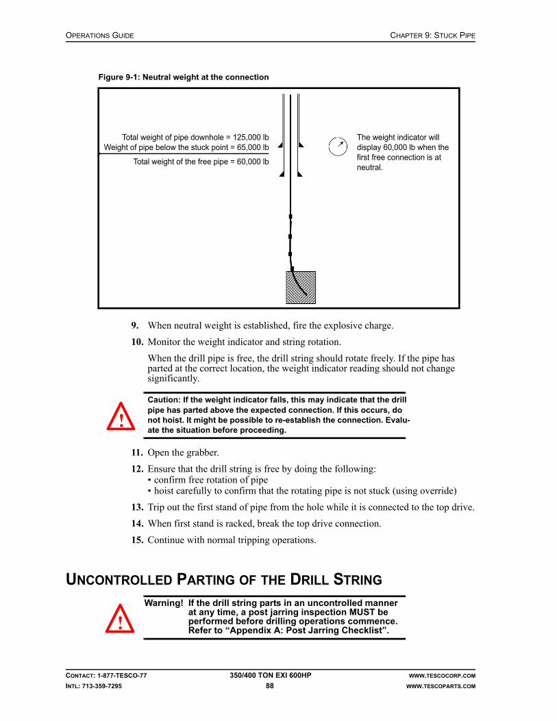
OPERATIONS GUIDE CHAPTER 9: STUCK PIPE
CONTACT: 1-877-TESCO-77 350/400 TON EXI 600HP WWW.TESCOCORP.COM
INTL: 713-359-7295 88 WWW.TESCOPARTS.COM
9. When neutral weight is established, fire the explosive charge.
10. Monitor the weight indicator and string rotation.
When the drill pipe is free, the drill string should rotate freely. If the pipe has parted at the correct location, the weight indicator reading should not change significantly.
Caution: If the weight indicator falls, this may indicate that the drill pipe has parted above the expected connection. If this occurs, do not hoist. It might be possible to re-establish the connection. Evalu-ate the situation before proceeding.
11. Open the grabber.
12. Ensure that the drill string is free by doing the following:• confirm free rotation of pipe• hoist carefully to confirm that the rotating pipe is not stuck (using override)
13. Trip out the first stand of pipe from the hole while it is connected to the top drive.
14. When first stand is racked, break the top drive connection.
15. Continue with normal tripping operations.
UNCONTROLLED PARTING OF THE DRILL STRING
Warning! If the drill string parts in an uncontrolled manner at any time, a post jarring inspection MUST be performed before drilling operations commence. Refer to “Appendix A: Post Jarring Checklist”.
Figure 9-1: Neutral weight at the connection
Total weight of pipe downhole = 125,000 lbWeight of pipe below the stuck point = 65,000 lb
Total weight of the free pipe = 60,000 lb
The weight indicator will display 60,000 lb when the first free connection is at neutral.
!
!

CHAPTER 10: RUN AND PULL CASING OPERATIONS GUIDE
CONTACT: 1-877-TESCO-77 350/400 TON EXI 600HP WWW.TESCOCORP.COM
INTL: 713-359-7295 89 WWW.TESCOPARTS.COM
CHAPTER 10: RUN AND PULL CASING
There are advantages to using the TESCO top drive to run casing:
• Fill-up tools can be connected directly to the top drive to provide fill-up capability while running the casing.
• The TILT and EXTEND functions can be used to assist rig personnel in handling and stabbing the casing.
Figure 10-1: Pick up casing
1. Floor slip elevators2. Working platform
(optional)3. Sling4. Casing Running
elevators5. Pick-up elevators

OPERATIONS GUIDE CHAPTER 10: RUN AND PULL CASING
CONTACT: 1-877-TESCO-77 350/400 TON EXI 600HP WWW.TESCOCORP.COM
INTL: 713-359-7295 90 WWW.TESCOPARTS.COM
PREPARE THE TOP DRIVE TO RUN CASING
1. If required, orient the pipe handler so that the elevator links can be tilted toward the V-door.
2. Remove the hydraulic elevator from the elevator links.
3. If required, remove the elevator links.Note: Longer elevator links are often required when casing is being run. Use the floor tugger to attach the longer links.
Caution: If using elevator links longer than 12 ft (3.7 m), do not use the LINK TILT function. Consult a TESCO representative if links longer than 12 ft (3.7 m) must be used.
4. Pick up the casing running elevators.
5. If casing fill-up apparatus is required, use the grabber and the top drive to connect it to the top drive saver sub.
6. If using the top drive to bring casing up the V-door and onto the rig floor, use a set of pick-up elevators and slings:• Attach the ‘pick-up elevator’ slings such that the single-joint pick-up elevators
hang approximately 3 to 4 ft (0.9 to 1.2 m) below the main elevator.• Attach the ‘pick-up elevator’ slings to the pick-up elevators.
7. Ensure that a working platform and floor elevators are installed and operational if required.
Warning! Use a crane or a “tail-in” line to assist in lifting large diameter, heavy weight casing from the V-door to the rig floor. If this precaution is not taken, the weight of the casing will pull the top drive away from the torque track. This can damage the EXTEND components of the torque arrest system.
!
!
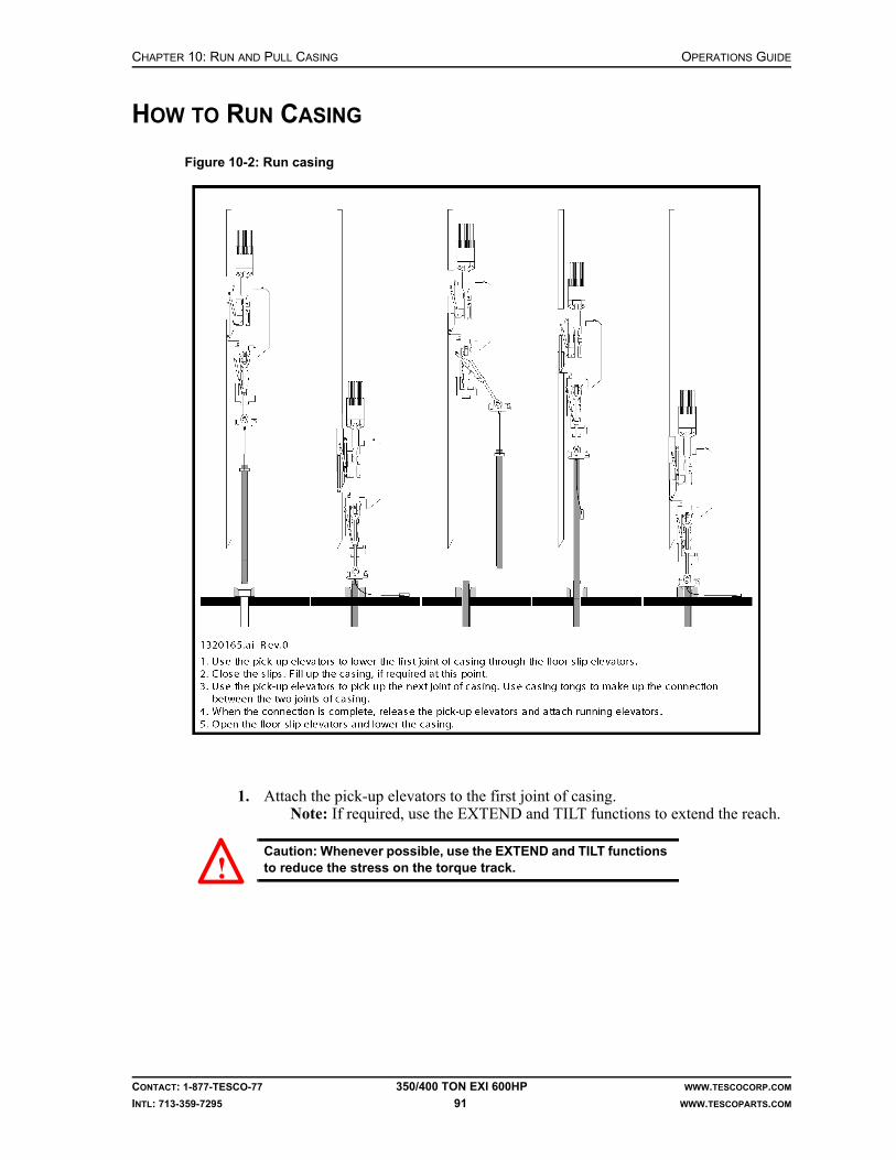
CHAPTER 10: RUN AND PULL CASING OPERATIONS GUIDE
CONTACT: 1-877-TESCO-77 350/400 TON EXI 600HP WWW.TESCOCORP.COM
INTL: 713-359-7295 91 WWW.TESCOPARTS.COM
HOW TO RUN CASING
1. Attach the pick-up elevators to the first joint of casing.Note: If required, use the EXTEND and TILT functions to extend the reach.
Caution: Whenever possible, use the EXTEND and TILT functions to reduce the stress on the torque track.
Figure 10-2: Run casing
!

OPERATIONS GUIDE CHAPTER 10: RUN AND PULL CASING
CONTACT: 1-877-TESCO-77 350/400 TON EXI 600HP WWW.TESCOCORP.COM
INTL: 713-359-7295 92 WWW.TESCOPARTS.COM
2. Ensure that floor personnel are ready to control the bottom of the casing joint.
3. Slowly hoist the top drive to move the casing to the drill floor.
Warning! The weight of the casing tends to pull the top drive away from the torque track. This strains the stabilization devices for the torque track.
Warning! If the top drive is extended toward the casing when hoisted, it could collide with the racking platform.
4. Hoist the casing until it is above the rig floor.
5. Lower the casing into the wellbore to the desired connection height.
6. Set the slips onto the casing.
7. Attach a safety clamp.
8. Unlatch the pick-up elevators.
9. If required, lower the top drive to stab the fill-up tool into the casing stump.
10. Fill the casing as required.
11. Repeat Steps 1 to 4 for the second joint of casing, then continue with the follow-ing steps.
12. Lower the second joint of casing until its pin end enters the box end of the casing in the slips.
Note: The TILT and EXTEND functions can also be used to assist in aligning the casing joints.
13. Use casing tongs to make up the casing connection.
14. After the connection is made up securely, remove the pick-up elevators.
15. Latch the casing running elevators onto the top joint of casing.
16. Remove the safety clamp.
17. Hoist the casing.
Figure 10-3: Reduce the stress on the torque track
Incorrect Good Better
!
!

CHAPTER 10: RUN AND PULL CASING OPERATIONS GUIDE
CONTACT: 1-877-TESCO-77 350/400 TON EXI 600HP WWW.TESCOCORP.COM
INTL: 713-359-7295 93 WWW.TESCOPARTS.COM
18. Remove the slips.
19. Lower the casing into the wellbore to the desired connection height.
20. Attach a safety clamp.
21. Set the slips on the casing.
22. Unlatch the casing running elevators.
23. If required, lower the top drive the stab the fill-up tool into the casing stump.
24. Fill the casing as required.
25. Repeat this procedure as required for all joints of casing.
HOW TO PULL CASING
1. Attach casing running elevators to the top joint of casing.
2. Remove the slips.
3. Hoist the top drive until the entire joint of casing is above the rig floor.
4. Set the slips.
5. Unlatch the running elevators from the casing.
6. Attach the pick-up elevators to the casing.
7. Use casing tongs to break and unscrew the casing connection.
8. Hoist the top drive and the casing joint.
9. Use the EXTEND and TILT functions to move the casing toward the V-door.
10. Ensure that rig personnel are in place to guide the bottom of the casing joint.
11. Lower the top drive slowly and allow floor personnel to control the bottom of the casing.
12. When the casing is secured in the V-door, unlatch the pick-up elevators.
13. Repeat this procedure for all casing joints.
Caution: When reaching the last few lengths of casing, it may be necessary to use a safety clamp to ensure the casing does not slide through the slips.
!

OPERATIONS GUIDE CHAPTER 10: RUN AND PULL CASING
CONTACT: 1-877-TESCO-77 350/400 TON EXI 600HP WWW.TESCOCORP.COM
INTL: 713-359-7295 94 WWW.TESCOPARTS.COM
This page has been left blank intentionally.

CHAPTER 11: TOP DRIVE CONSIDERATIONS OPERATIONS GUIDE
CONTACT: 1-877-TESCO-77 350/400 TON EXI 600HP WWW.TESCOCORP.COM
INTL: 713-359-7295 95 WWW.TESCOPARTS.COM
CHAPTER 11: TOP DRIVE CONSIDERATIONS
SLIP AND CUT OPERATIONS
Mud circulation can be maintained while performing slip and cut operations.
Caution: Never suspend the weight of the top drive from the torque tube during slip and cut operations. Instead, rest part of the weight of the top drive on a single length of drill pipe secured in the rotary table, and suspend the remainder of the weight from the block sling.
1. Obtain and install a new block sling.
Note: Size this block sling so that it will support the top drive, swivel and blocks close to the rig floor.
2. Connect the top drive to a single length of drill pipe.
3. Raise the top drive and connect the block sling.
4. Use the blocks to lower the top drive and the single length of pipe.
Figure 11-1: Block sling
!

OPERATIONS GUIDE CHAPTER 11: TOP DRIVE CONSIDERATIONS
CONTACT: 1-877-TESCO-77 350/400 TON EXI 600HP WWW.TESCOCORP.COM
INTL: 713-359-7295 96 WWW.TESCOPARTS.COM
5. Lower the pipe through the rotary table.Note: To lower the top drive to the rig floor, tilt the links as far back as possible. Maintain enough clearance so that the front cover of the drawworks can be removed for servicing.
6. When the block sling is almost tight, stop lowering the top drive.Note: Balance the weight of the top drive between the block hanging sling and the pipe in the slips.
7. Set the slips.
CEMENTING OPERATIONS
Do not run cement through the top drive unless it is absolutely necessary. Cement causes wear and, if allowed to harden, will irreparably damage the top drive.
If suspending a cement head from the top drive elevator ensure the following conditions exist:
• The elevator links are long enough to accommodate the cement head.• The elevator hydraulic hoses are disconnected.
Note: Disconnect the hydraulic hose when the cement head is in position and the elevators are closed.
When using a flow-through cement head, some cement might enter the quill and mud valve. After completing cementing operations, TESCO advises that the quill, mudsaver valve and lower Kelly valve be flushed thoroughly. Operate the mudsaver and Kelly valves to ensure they work properly.
Danger! Failure to perform these operational checks can compromise rig safety!
SLICKLINE SURVEY AND WIRELINE LOGGING OPERATIONS
Several issues must be addressed when using a top drive for slickline or wireline operations.
When using a turn-down sheave, use the following conventions:
• Orient the elevator links so they are parallel to the direction of line travel.• Remove the elevator hydraulic hoses when suspending the turn-down sheave from the
elevator. This prevents accidental opening of the elevator.
!
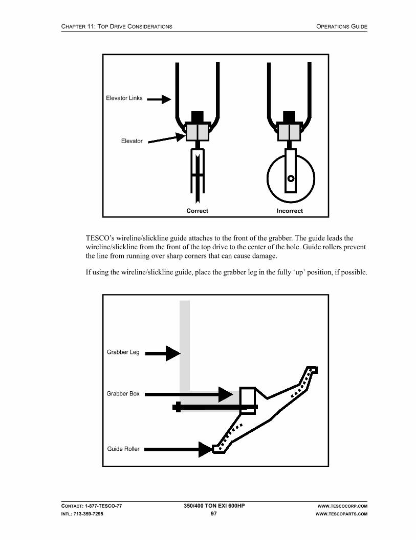
CHAPTER 11: TOP DRIVE CONSIDERATIONS OPERATIONS GUIDE
CONTACT: 1-877-TESCO-77 350/400 TON EXI 600HP WWW.TESCOCORP.COM
INTL: 713-359-7295 97 WWW.TESCOPARTS.COM
TESCO’s wireline/slickline guide attaches to the front of the grabber. The guide leads the wireline/slickline from the front of the top drive to the center of the hole. Guide rollers prevent the line from running over sharp corners that can cause damage.
If using the wireline/slickline guide, place the grabber leg in the fully ‘up’ position, if possible.
Elevator Links
Elevator
Correct Incorrect
Grabber Leg
Grabber Box
Guide Roller
OPERATIONS GUIDE CHAPTER 11: TOP DRIVE CONSIDERATIONS
CONTACT: 1-877-TESCO-77 350/400 TON EXI 600HP WWW.TESCOCORP.COM
INTL: 713-359-7295 98 WWW.TESCOPARTS.COM
HEAVY LOADS AT THE V-DOOR
This procedure describes how to use the top drive to pick up heavy loads from the V-door.
Warning! The extend frame and EXTEND function handle drilling tools, pick up casing, and rack drill pipe and collars. They are for convenience only and are not designed to pick-up heavy loads while extended.
Warning! Exercise care, attention and common sense when applying the following procedure to pick up heavy loads from the V-door using the top drive.
1. Connect the elevator links on the top drive to the load being picked up. Use slings that are strong enough to support the load.
2. Connect a rig winch to the load being picked up.
3. Hoist the top drive with the extend frame completely retracted until the slings are tight and the top drive is beginning to pick up the load.
4. At this point, hold the EXTEND switch at the IN position to maintain pressure on the extend cylinders. This will prevent the extend frame from “opening up” while the load is lifted. The force of gravity, combined with the load and the angle at which it is being lifted, will tend to pull the extend frame open.
5. If the load is too heavy, and holding the EXTEND switch in the IN position is not sufficient to keep the extend frame retracted, pick up the load with the rig winch. This will create less pull on the extend frame and allow it to stay retracted. The top drive, with the extend frame retracted, can be hoisted vertically with no chance of the torque bushing binding on the torque track.
6. Continue to hoist the load until it is at the level required.
Warning! The extend frame must remain retracted at all times when hoisting any heavy load. If it is allowed to extend, the torque bushing can bind on the torque track and damage the extend frame and extend cylinders. For this reason, always use a rig winch to help lift the load. If done carefully, most normal drilling equipment can be lifted using the above procedure.
Warning! For extremely heavy loads, TESCO recommends using either additional winches to assist in the lift or use cranes to position the equipment on the drill floor instead of picking them up with the top drive. Damage to the top drive and unnecessary repair time can be avoided with proper planning and preparation.
!
!
!
!

APPENDIX A: POST JARRING CHECKLIST OPERATIONS GUIDE
CONTACT: 1-877-TESCO-77 350/400 TON EXI 600HP WWW.TESCOCORP.COM
INTL: 713-359-7295 99 WWW.TESCOPARTS.COM
APPENDIX A: POST JARRING CHECKLIST

OPERATIONS GUIDE APPENDIX A: POST JARRING CHECKLIST
CONTACT: 1-877-TESCO-77 350/400 TON EXI 600HP WWW.TESCOCORP.COM
INTL: 713-359-7295 100 WWW.TESCOPARTS.COM
This page has been left blank intentionally.
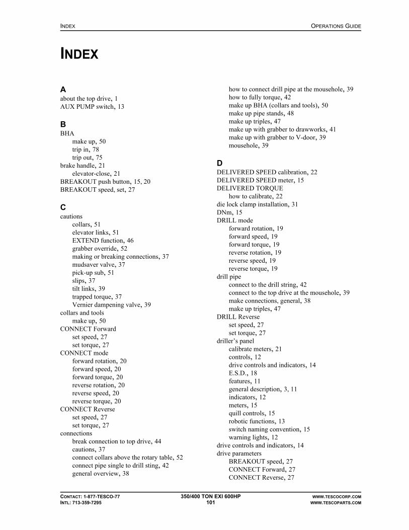
INDEX OPERATIONS GUIDE
CONTACT: 1-877-TESCO-77 350/400 TON EXI 600HP WWW.TESCOCORP.COM
INTL: 713-359-7295 101 WWW.TESCOPARTS.COM
INDEX
Aabout the top drive, 1AUX PUMP switch, 13
BBHA
make up, 50trip in, 78trip out, 75
brake handle, 21elevator-close, 21
BREAKOUT push button, 15, 20BREAKOUT speed, set, 27
Ccautions
collars, 51elevator links, 51EXTEND function, 46grabber override, 52making or breaking connections, 37mudsaver valve, 37pick-up sub, 51slips, 37tilt links, 39trapped torque, 37Vernier dampening valve, 39
collars and toolsmake up, 50
CONNECT Forwardset speed, 27set torque, 27
CONNECT modeforward rotation, 20forward speed, 20forward torque, 20reverse rotation, 20reverse speed, 20reverse torque, 20
CONNECT Reverseset speed, 27set torque, 27
connectionsbreak connection to top drive, 44cautions, 37connect collars above the rotary table, 52connect pipe single to drill sting, 42general overview, 38
how to connect drill pipe at the mousehole, 39how to fully torque, 42make up BHA (collars and tools), 50make up pipe stands, 48make up triples, 47make up with grabber to drawworks, 41make up with grabber to V-door, 39mousehole, 39
DDELIVERED SPEED calibration, 22DELIVERED SPEED meter, 15DELIVERED TORQUE
how to calibrate, 22die lock clamp installation, 31DNm, 15DRILL mode
forward rotation, 19forward speed, 19forward torque, 19reverse rotation, 19reverse speed, 19reverse torque, 19
drill pipeconnect to the drill string, 42connect to the top drive at the mousehole, 39make connections, general, 38make up triples, 47
DRILL Reverseset speed, 27set torque, 27
driller’s panelcalibrate meters, 21controls, 12drive controls and indicators, 14E.S.D., 18features, 11general description, 3, 11indicators, 12meters, 15quill controls, 15robotic functions, 13switch naming convention, 15warning lights, 12
drive controls and indicators, 14drive parameters
BREAKOUT speed, 27CONNECT Forward, 27CONNECT Reverse, 27

OPERATIONS GUIDE INDEX
CONTACT: 1-877-TESCO-77 350/400 TON EXI 600HP WWW.TESCOCORP.COM
INTL: 713-359-7295 102 WWW.TESCOPARTS.COM
DRILL Reverse, 27how to set or change, 26overview, 26
DRIVE SET switch, 14
EELEVATOR function description, 16ELEVATOR switch, 13ELEVATOR-CLOSE
brake handle, 21ELEVATOR-SAFETY-OPEN, 16emergency shut down (E.S.D.)
description, 18on the driller’s panel, 18on the main panel, 18push button, 14reset, 18
ENABLE switch, 14EXTEND function
cautions, 46description, 16
EXTEND switch, 13
FFLOAT push button, 13function descriptions
ELEVATOR, 16EXTEND, 16GRABBER, 17PIPE HANDLER, 18TILT, 16VALVE, 17
GGRABBER ’CLOSED’ light, 14GRABBER function description, 17GRABBER switch, 14GRABBER-Drawworks override, 21
Iinformation, where to find more, 1
Mmake connections
general, 38precautions, 38
metersdriller’s panel, 15how to calibrate, 21, 22
MODE switch, 15MODULE ’ON’ light, 14mousehole
make up stands, 48use to make connections, 39
mudsaver valvecautions, 37
Nnaming conventions for switch settings, 15
Ooverride
ELEVATOR-CLOSE, 21GRABBER-Drawworks, 21
Ppipe
break connection with top drive, 44connect to drill string, 42make up triples, 47
pipe handlerfunction description, 18
PIPE HANDLER ’CAUTION’ light, 14PIPE HANDLER ROTATE push button, 14PIPE HANDLER switch, 14pipe stands
make up in mousehole, 48make up in rotary table, 45
pre-operational proceduresinstall the die lock clamp, 31install the saver sub, 31
Qquill rotation controls, 15QUILL switch, 15
RREADY light, 14remote brake handle, 21RESET push button, 14robotic functions
controls and indicators, 13ROBOTICS ’ON’ light, 13rotary table
connect collars, 52make up pipe stands, 45
SSAFETY OPEN push button, 13saver sub installation, 31SET SPEED
how to calibrate, 22SET TORQUE calibration, 22SET TORQUE meter, 15

INDEX OPERATIONS GUIDE
CONTACT: 1-877-TESCO-77 350/400 TON EXI 600HP WWW.TESCOCORP.COM
INTL: 713-359-7295 103 WWW.TESCOPARTS.COM
speed available, 19SPEED switch, 15System Description, 3
TTILT function description, 16TILT switch, 13torque
trapped in drill string, 37torque available, 19torque meter, display DNm, 15TORQUE switch, 15torquing connections, 42
VVALVE ’CLOSED’ light, 14VALVE function description, 17VALVE switch, 13

OPERATIONS GUIDE INDEX
CONTACT: 1-877-TESCO-77 350/400 TON EXI 600HP WWW.TESCOCORP.COM
INTL: 713-359-7295 104 WWW.TESCOPARTS.COM
This page has been left blank intentionally.
OPERATIONS GUIDE
CONTACT: 1-877-TESCO-77 350/400 TON EXI 600HP WWW.TESCOCORP.COM
INTL: 713-359-7295 105 WWW.TESCOPARTS.COM
ENGINEERING SIGN-OFF
This sign-off sheet indicates that this document has been approved for release by the Engineering Department at TESCO.
Document Complete By Signature Date Signed
Document Reviewed/Approved Date Signed
chane
Typewritten Text
Edward ChanFeb 4, 2010
madejskm
Typewritten Text
Feb 4, 2010

OPERATIONS GUIDE
CONTACT: 1-877-TESCO-77 350/400 TON EXI 600HP WWW.TESCOCORP.COM
INTL: 713-359-7295 106 WWW.TESCOPARTS.COM
This page has been left blank intentionally.

DOCUMENT NAME: 880079 REV 2
Maintenance Guide
EXI Top Drive System
350/400 TON EXI 600HP


COPYRIGHT AND DISCLAIMER MAINTENANCE GUIDE
CONTACT: 1-877-TESCO-77 350/400 TON EXI 600HP WWW.TESCOCORP.COM
INTL: 713-359-7295 I WWW.TESCOPARTS.COM
Tesco Corporation (“TESCO”) has made every effort to ensure that this document contains accurate and current information for the TESCO top drive, however, the document is intended to be used in conjunction with a complete training program and on-site supervision and TESCO does not warrant or guarantee that the information contained herein is either complete or accurate in every respect, and the reader hereby protects, indemnifies and holds harmless Tesco Corporation together with its directors, officers, employees and agents from and against all liability for personal injury, death or property damage to any person arising directly or indirectly from the use by the reader of the information contained in the document.
This equipment was filled at the factory with TESCO ULTREX™ brand fluids and greases. To ensure maximum performance and to avoid cross-contamination, we strongly recommend the continued usage of TESCO ULTREX™ lubricants, unless otherwise specified.
TESCO ULTREX™ is a trademark and TESCO® is a registered trademark of Tesco Corporation.
Tesco Corporation © 2009
Contact Information
Corporate Head Office3993 W. Sam Houston Parkway No., Suite 100
Houston, Texas, 77043USA
www.tescocorp.comwww.tescoparts.com
Telephone: (713) 359-7000Fax: (713) 359-7001
After Market Sales and Service ContactToll Free North America: 1-877-TESCO-77
International: 713-359-7295

REVISION INFORMATION MAINTENANCE GUIDE
CONTACT: 1-877-TESCO-77 350/400 TON EXI 600HP WWW.TESCOCORP.COM
INTL: 713-359-7295 II WWW.TESCOPARTS.COM
Revision Information
Version Date Description of Changes
Rev 0 August 2007 First release of document
Rev 1 October 2008 Upgrade 350 EXI 600 to 350/400 EXI 600
Rev 2 September 2009 Added TESCO ULTREX™ recommendations and updated the footer to contain contact information.
TABLE OF CONTENTS MAINTENANCE GUIDE
CONTACT: 1-877-TESCO-77 350/400 TON EXI 600HP WWW.TESCOCORP.COM
INTL: 713-359-7295 III WWW.TESCOPARTS.COM
TABLE OF CONTENTS
LIST OF FIGURES . . . . . . . . . . . . . . . . . . . . . . . . . . . . . . . . . . . . . . . . . . . . . . . . . . . . . 1
LIST OF TABLES . . . . . . . . . . . . . . . . . . . . . . . . . . . . . . . . . . . . . . . . . . . . . . . . . . . . . . 1
SAFETY INSTRUCTIONS . . . . . . . . . . . . . . . . . . . . . . . . . . . . . . . . . . . . . . . . . . . . . . . . . 3
CHAPTER 1: ABOUT THIS DOCUMENT . . . . . . . . . . . . . . . . . . . . . . . . . . . . . . . . . . . . . . 1
CHAPTER 2: MAINTENANCE AND SERVICE SCHEDULES . . . . . . . . . . . . . . . . . . . . . . . . . 3
Lock-Out Methods. . . . . . . . . . . . . . . . . . . . . . . . . . . . . . . . . . . . . . . . . . . . . . . . . . . . . . . . . . . . . . . . . 3
Fluid Specification and Capacity Summary . . . . . . . . . . . . . . . . . . . . . . . . . . . . . . . . . . . . . . . . . . . . 5
Top Drive Service Requirements . . . . . . . . . . . . . . . . . . . . . . . . . . . . . . . . . . . . . . . . . . . . . . . . . . . . . 5
Daily Top Drive Service . . . . . . . . . . . . . . . . . . . . . . . . . . . . . . . . . . . . . . . . . . . . . . . . . . . . . . . . . . 5
Inspection. . . . . . . . . . . . . . . . . . . . . . . . . . . . . . . . . . . . . . . . . . . . . . . . . . . . . . . . . . . . . . . . . . . . . . . . . . . . . . . . . . . . . . . 5
Lubrication . . . . . . . . . . . . . . . . . . . . . . . . . . . . . . . . . . . . . . . . . . . . . . . . . . . . . . . . . . . . . . . . . . . . . . . . . . . . . . . . . . . . . . 6
Weekly Top Drive Service . . . . . . . . . . . . . . . . . . . . . . . . . . . . . . . . . . . . . . . . . . . . . . . . . . . . . . . . 6
Monthly (Periodic) Top Drive Service . . . . . . . . . . . . . . . . . . . . . . . . . . . . . . . . . . . . . . . . . . . . . . . . 7
Six-Month Top Drive Service . . . . . . . . . . . . . . . . . . . . . . . . . . . . . . . . . . . . . . . . . . . . . . . . . . . . . . 8
1,000 Operating Day Top Drive Service. . . . . . . . . . . . . . . . . . . . . . . . . . . . . . . . . . . . . . . . . . . . . . 8
Driller’s Panel Service Requirements . . . . . . . . . . . . . . . . . . . . . . . . . . . . . . . . . . . . . . . . . . . . . . . . 11
Monthly Driller’s Panel Service. . . . . . . . . . . . . . . . . . . . . . . . . . . . . . . . . . . . . . . . . . . . . . . . . . . . 11
Service Loop Service Requirements . . . . . . . . . . . . . . . . . . . . . . . . . . . . . . . . . . . . . . . . . . . . . . . . . 11
Weekly Service Loop Service. . . . . . . . . . . . . . . . . . . . . . . . . . . . . . . . . . . . . . . . . . . . . . . . . . . . . 11
Monthly (Periodic) Service Loop Service . . . . . . . . . . . . . . . . . . . . . . . . . . . . . . . . . . . . . . . . . . . . 11
1,000 Operating Day Service Loop Service . . . . . . . . . . . . . . . . . . . . . . . . . . . . . . . . . . . . . . . . . . 12
Torque Arrest System Service Requirements . . . . . . . . . . . . . . . . . . . . . . . . . . . . . . . . . . . . . . . . . 12
Daily Torque Arrest System Service. . . . . . . . . . . . . . . . . . . . . . . . . . . . . . . . . . . . . . . . . . . . . . . . 12
Weekly Torque Arrest System Service. . . . . . . . . . . . . . . . . . . . . . . . . . . . . . . . . . . . . . . . . . . . . . 12
Auxiliary Hydraulic Power Unit Service Requirements . . . . . . . . . . . . . . . . . . . . . . . . . . . . . . . . . . 13
Daily Auxiliary Hydraulic Power Unit Service . . . . . . . . . . . . . . . . . . . . . . . . . . . . . . . . . . . . . . . . . 13
Weekly Auxiliary Hydraulic Power Unit Service . . . . . . . . . . . . . . . . . . . . . . . . . . . . . . . . . . . . . . . 13
Monthly (Periodic) Auxiliary Hydraulic Power Unit Service . . . . . . . . . . . . . . . . . . . . . . . . . . . . . . 13
1,000 Operating Day Auxiliary Hydraulic Power Unit Service . . . . . . . . . . . . . . . . . . . . . . . . . . . . 14
Power Module Service Requirements . . . . . . . . . . . . . . . . . . . . . . . . . . . . . . . . . . . . . . . . . . . . . . . . 14
Daily Power Module Service. . . . . . . . . . . . . . . . . . . . . . . . . . . . . . . . . . . . . . . . . . . . . . . . . . . . . . 14
Condensation . . . . . . . . . . . . . . . . . . . . . . . . . . . . . . . . . . . . . . . . . . . . . . . . . . . . . . . . . . . . . . . . . 14
Weekly Power Module Service. . . . . . . . . . . . . . . . . . . . . . . . . . . . . . . . . . . . . . . . . . . . . . . . . . . . 15
Monthly (Periodic) Power Module Service . . . . . . . . . . . . . . . . . . . . . . . . . . . . . . . . . . . . . . . . . . . 15
MAINTENANCE GUIDE TABLE OF CONTENTS
CONTACT: 1-877-TESCO-77 350/400 TON EXI 600HP WWW.TESCOCORP.COM
INTL: 713-359-7295 IV WWW.TESCOPARTS.COM
CHAPTER 3: NON-DESTRUCTIVE TESTING AND INSPECTION SCHEDULES . . . . . . . . . . . .17
Top Drive Owner’s Guidelines . . . . . . . . . . . . . . . . . . . . . . . . . . . . . . . . . . . . . . . . . . . . . . . . . . . . . .17
Guidelines for Component Inspectors. . . . . . . . . . . . . . . . . . . . . . . . . . . . . . . . . . . . . . . . . . . . . . . .18
Load Path Components and Inspection Information . . . . . . . . . . . . . . . . . . . . . . . . . . . . . . . . . . . .18
Inspection Types . . . . . . . . . . . . . . . . . . . . . . . . . . . . . . . . . . . . . . . . . . . . . . . . . . . . . . . . . . . . . . .19
Threaded Connections . . . . . . . . . . . . . . . . . . . . . . . . . . . . . . . . . . . . . . . . . . . . . . . . . . . . . . . . . . . .29
Threaded Connection Inspection Frequency (EXI 600) . . . . . . . . . . . . . . . . . . . . . . . . . . . . . . . . .29
Torque Arrest System . . . . . . . . . . . . . . . . . . . . . . . . . . . . . . . . . . . . . . . . . . . . . . . . . . . . . . . . . . . . .29
CHAPTER 4: SERVICE PROCEDURES . . . . . . . . . . . . . . . . . . . . . . . . . . . . . . . . . . . . . . .37
Introduction . . . . . . . . . . . . . . . . . . . . . . . . . . . . . . . . . . . . . . . . . . . . . . . . . . . . . . . . . . . . . . . . . . . . .37
How to Disassemble and Service the Roto-Actuator . . . . . . . . . . . . . . . . . . . . . . . . . . . . . . . . . . . .40
Re-assembly . . . . . . . . . . . . . . . . . . . . . . . . . . . . . . . . . . . . . . . . . . . . . . . . . . . . . . . . . . . . . . . . . .41
How to Set the Counter-Balance Cushion Height. . . . . . . . . . . . . . . . . . . . . . . . . . . . . . . . . . . . . . .42
How to Set the Secondary Pressure Relief Valve for the Auxiliary System . . . . . . . . . . . . . . . . . .44
How to Set the Main Pressure Relief Valve for the Auxiliary System . . . . . . . . . . . . . . . . . . . . . . .45
How to Set the Function Light Pressure Switch for the Auxiliary System . . . . . . . . . . . . . . . . . . .46
How to Check and Adjust Preload for the Quill Upper Bearing. . . . . . . . . . . . . . . . . . . . . . . . . . . .47
How to Check for Quill End Play . . . . . . . . . . . . . . . . . . . . . . . . . . . . . . . . . . . . . . . . . . . . . . . . . . .47
How to Calculate the Preload Adjustment. . . . . . . . . . . . . . . . . . . . . . . . . . . . . . . . . . . . . . . . . . . .48
How to Adjust the Preload. . . . . . . . . . . . . . . . . . . . . . . . . . . . . . . . . . . . . . . . . . . . . . . . . . . . . . . .49
CHAPTER 5: DISASSEMBLY AND ASSEMBLY INSTRUCTIONS . . . . . . . . . . . . . . . . . . . . . .51Install the Mudsaver Valve . . . . . . . . . . . . . . . . . . . . . . . . . . . . . . . . . . . . . . . . . . . . . . . . . . . . . . .51
How to Disassemble and Assemble the Grabber . . . . . . . . . . . . . . . . . . . . . . . . . . . . . . . . . . . . . . .53
Introduction . . . . . . . . . . . . . . . . . . . . . . . . . . . . . . . . . . . . . . . . . . . . . . . . . . . . . . . . . . . . . . . . . . .53
How to Change the Grabber Dies . . . . . . . . . . . . . . . . . . . . . . . . . . . . . . . . . . . . . . . . . . . . . . . . . .53
How to Remove the Grabber Actuating Piston . . . . . . . . . . . . . . . . . . . . . . . . . . . . . . . . . . . . . . . .54
How to Reinstall the Grabber Actuating Piston . . . . . . . . . . . . . . . . . . . . . . . . . . . . . . . . . . . . . . . .56
How to Repair the Grabber Cylinder . . . . . . . . . . . . . . . . . . . . . . . . . . . . . . . . . . . . . . . . . . . . . . . .56
How to Remove and Reinstall the Grabber Leg . . . . . . . . . . . . . . . . . . . . . . . . . . . . . . . . . . . . . . .57
Remove the Grabber Leg . . . . . . . . . . . . . . . . . . . . . . . . . . . . . . . . . . . . . . . . . . . . . . . . . . . . . . . . . . . . . . . . . . . . . . . . . . 58
Reinstall the Grabber Leg. . . . . . . . . . . . . . . . . . . . . . . . . . . . . . . . . . . . . . . . . . . . . . . . . . . . . . . . . . . . . . . . . . . . . . . . . . 58
CHAPTER 6: LONG TERM PRESERVATION AND STORAGE. . . . . . . . . . . . . . . . . . . . . . . .59
Introduction . . . . . . . . . . . . . . . . . . . . . . . . . . . . . . . . . . . . . . . . . . . . . . . . . . . . . . . . . . . . . . . . . . . . .59
Before System Shut Down . . . . . . . . . . . . . . . . . . . . . . . . . . . . . . . . . . . . . . . . . . . . . . . . . . . . . . . . .59
Top Drive. . . . . . . . . . . . . . . . . . . . . . . . . . . . . . . . . . . . . . . . . . . . . . . . . . . . . . . . . . . . . . . . . . . . . . . .60
Junction Boxes . . . . . . . . . . . . . . . . . . . . . . . . . . . . . . . . . . . . . . . . . . . . . . . . . . . . . . . . . . . . . . . .60
Motor Termination Junction Boxes . . . . . . . . . . . . . . . . . . . . . . . . . . . . . . . . . . . . . . . . . . . . . . . . . . . . . . . . . . . . . . . . . . . 60
Top Drive Junction Box. . . . . . . . . . . . . . . . . . . . . . . . . . . . . . . . . . . . . . . . . . . . . . . . . . . . . . . . . . . . . . . . . . . . . . . . . . . . 60
TABLE OF CONTENTS MAINTENANCE GUIDE
CONTACT: 1-877-TESCO-77 350/400 TON EXI 600HP WWW.TESCOCORP.COM
INTL: 713-359-7295 V WWW.TESCOPARTS.COM
Quill . . . . . . . . . . . . . . . . . . . . . . . . . . . . . . . . . . . . . . . . . . . . . . . . . . . . . . . . . . . . . . . . . . . . . . . . 60
Load Nut (where applicable). . . . . . . . . . . . . . . . . . . . . . . . . . . . . . . . . . . . . . . . . . . . . . . . . . . . . . 60
Grabber Leg . . . . . . . . . . . . . . . . . . . . . . . . . . . . . . . . . . . . . . . . . . . . . . . . . . . . . . . . . . . . . . . . . . 61
Pipe Handler. . . . . . . . . . . . . . . . . . . . . . . . . . . . . . . . . . . . . . . . . . . . . . . . . . . . . . . . . . . . . . . . . . 61
Hydraulics. . . . . . . . . . . . . . . . . . . . . . . . . . . . . . . . . . . . . . . . . . . . . . . . . . . . . . . . . . . . . . . . . . . . 61
Swivel Links, Yoke, and Counter Balance . . . . . . . . . . . . . . . . . . . . . . . . . . . . . . . . . . . . . . . . . . . 61
Extend Frame and Mount . . . . . . . . . . . . . . . . . . . . . . . . . . . . . . . . . . . . . . . . . . . . . . . . . . . . . . . . 62
Elevators. . . . . . . . . . . . . . . . . . . . . . . . . . . . . . . . . . . . . . . . . . . . . . . . . . . . . . . . . . . . . . . . . . . . . 62
Mudsaver Valve . . . . . . . . . . . . . . . . . . . . . . . . . . . . . . . . . . . . . . . . . . . . . . . . . . . . . . . . . . . . . . . 62
Saver Subs . . . . . . . . . . . . . . . . . . . . . . . . . . . . . . . . . . . . . . . . . . . . . . . . . . . . . . . . . . . . . . . . . . . 63
Service Loop Storage Reel, Cables and Hoses . . . . . . . . . . . . . . . . . . . . . . . . . . . . . . . . . . . . . . . . 63
Driller’s Panel . . . . . . . . . . . . . . . . . . . . . . . . . . . . . . . . . . . . . . . . . . . . . . . . . . . . . . . . . . . . . . . . . . . 63
Interlocks . . . . . . . . . . . . . . . . . . . . . . . . . . . . . . . . . . . . . . . . . . . . . . . . . . . . . . . . . . . . . . . . . . . . 64
Torque Arrest System. . . . . . . . . . . . . . . . . . . . . . . . . . . . . . . . . . . . . . . . . . . . . . . . . . . . . . . . . . . . . 64
Torque Track Assembly . . . . . . . . . . . . . . . . . . . . . . . . . . . . . . . . . . . . . . . . . . . . . . . . . . . . . . . . . 64
Torque Bushing/Extend Frame. . . . . . . . . . . . . . . . . . . . . . . . . . . . . . . . . . . . . . . . . . . . . . . . . . . . 64
Hanging Assembly . . . . . . . . . . . . . . . . . . . . . . . . . . . . . . . . . . . . . . . . . . . . . . . . . . . . . . . . . . . . . 65
Torque Beam and T-Bar. . . . . . . . . . . . . . . . . . . . . . . . . . . . . . . . . . . . . . . . . . . . . . . . . . . . . . . . . 65
Hose Saddle and Components. . . . . . . . . . . . . . . . . . . . . . . . . . . . . . . . . . . . . . . . . . . . . . . . . . . . 65
Hydraulic Power Unit . . . . . . . . . . . . . . . . . . . . . . . . . . . . . . . . . . . . . . . . . . . . . . . . . . . . . . . . . . . . . 65
General. . . . . . . . . . . . . . . . . . . . . . . . . . . . . . . . . . . . . . . . . . . . . . . . . . . . . . . . . . . . . . . . . . . . . . 65
Auxiliary Hydraulics . . . . . . . . . . . . . . . . . . . . . . . . . . . . . . . . . . . . . . . . . . . . . . . . . . . . . . . . . . . . 65
Power Module . . . . . . . . . . . . . . . . . . . . . . . . . . . . . . . . . . . . . . . . . . . . . . . . . . . . . . . . . . . . . . . . . . . 66
Incoming Waterfall . . . . . . . . . . . . . . . . . . . . . . . . . . . . . . . . . . . . . . . . . . . . . . . . . . . . . . . . . . . . . 66
600 VAC Panel . . . . . . . . . . . . . . . . . . . . . . . . . . . . . . . . . . . . . . . . . . . . . . . . . . . . . . . . . . . . . . . . 66
120/208 VAC Panel . . . . . . . . . . . . . . . . . . . . . . . . . . . . . . . . . . . . . . . . . . . . . . . . . . . . . . . . . . . . 66
Drive System . . . . . . . . . . . . . . . . . . . . . . . . . . . . . . . . . . . . . . . . . . . . . . . . . . . . . . . . . . . . . . . . . 66
Drive Output Waterfall . . . . . . . . . . . . . . . . . . . . . . . . . . . . . . . . . . . . . . . . . . . . . . . . . . . . . . . . . . 66
APPENDIX A: TORQUE STANDARDS FOR HIGH STRENGTH FASTENERS. . . . . . . . . . . . . 67
Purpose . . . . . . . . . . . . . . . . . . . . . . . . . . . . . . . . . . . . . . . . . . . . . . . . . . . . . . . . . . . . . . . . . . . . . . . . 67
Standards. . . . . . . . . . . . . . . . . . . . . . . . . . . . . . . . . . . . . . . . . . . . . . . . . . . . . . . . . . . . . . . . . . . . . . . 67
Tables . . . . . . . . . . . . . . . . . . . . . . . . . . . . . . . . . . . . . . . . . . . . . . . . . . . . . . . . . . . . . . . . . . . . . . . . . . 68
APPENDIX B: TOOL JOINT USAGE CHART . . . . . . . . . . . . . . . . . . . . . . . . . . . . . . . . . . 71
APPENDIX C: MUD LOGGER OUTPUTS. . . . . . . . . . . . . . . . . . . . . . . . . . . . . . . . . . . . . 73
APPENDIX D: TORQUE SPECIFICATION OF ELECTRICAL FASTENERS . . . . . . . . . . . . . . . 75
APPENDIX E: SAMPLE INSPECTION LOGS . . . . . . . . . . . . . . . . . . . . . . . . . . . . . . . . . . 77
Quill Inspection Log . . . . . . . . . . . . . . . . . . . . . . . . . . . . . . . . . . . . . . . . . . . . . . . . . . . . . . . . . . . . . . 78
Load Nut Retainer and Split Collar Inspection Log . . . . . . . . . . . . . . . . . . . . . . . . . . . . . . . . . . . . 79

MAINTENANCE GUIDE TABLE OF CONTENTS
CONTACT: 1-877-TESCO-77 350/400 TON EXI 600HP WWW.TESCOCORP.COM
INTL: 713-359-7295 VI WWW.TESCOPARTS.COM
Mudsaver Valve Inspection Log . . . . . . . . . . . . . . . . . . . . . . . . . . . . . . . . . . . . . . . . . . . . . . . . . . . .80
Saver Sub Inspection Log . . . . . . . . . . . . . . . . . . . . . . . . . . . . . . . . . . . . . . . . . . . . . . . . . . . . . . . . .81
Load Collar Inspection Log . . . . . . . . . . . . . . . . . . . . . . . . . . . . . . . . . . . . . . . . . . . . . . . . . . . . . . . .82
Elevator Links Inspection Log . . . . . . . . . . . . . . . . . . . . . . . . . . . . . . . . . . . . . . . . . . . . . . . . . . . . . .83
Elevator Inspection Log . . . . . . . . . . . . . . . . . . . . . . . . . . . . . . . . . . . . . . . . . . . . . . . . . . . . . . . . . . .84
APPENDIX F: SERVICE CHECKLISTS . . . . . . . . . . . . . . . . . . . . . . . . . . . . . . . . . . . . . . .85
Daily Checklists . . . . . . . . . . . . . . . . . . . . . . . . . . . . . . . . . . . . . . . . . . . . . . . . . . . . . . . . . . . . . . . . . .85
Daily: Top Drive. . . . . . . . . . . . . . . . . . . . . . . . . . . . . . . . . . . . . . . . . . . . . . . . . . . . . . . . . . . . . . . .85
Daily: Torque Arrest System . . . . . . . . . . . . . . . . . . . . . . . . . . . . . . . . . . . . . . . . . . . . . . . . . . . . . .86
Daily: Auxiliary Hydraulic Power Unit . . . . . . . . . . . . . . . . . . . . . . . . . . . . . . . . . . . . . . . . . . . . . . .86
Daily: Power Module . . . . . . . . . . . . . . . . . . . . . . . . . . . . . . . . . . . . . . . . . . . . . . . . . . . . . . . . . . . .86
Weekly Checklists . . . . . . . . . . . . . . . . . . . . . . . . . . . . . . . . . . . . . . . . . . . . . . . . . . . . . . . . . . . . . . . .87
Weekly: Top Drive . . . . . . . . . . . . . . . . . . . . . . . . . . . . . . . . . . . . . . . . . . . . . . . . . . . . . . . . . . . . . .87
Weekly: Service Loop . . . . . . . . . . . . . . . . . . . . . . . . . . . . . . . . . . . . . . . . . . . . . . . . . . . . . . . . . . .87
Weekly: Torque Arrest System . . . . . . . . . . . . . . . . . . . . . . . . . . . . . . . . . . . . . . . . . . . . . . . . . . . .88
Weekly: Auxiliary Hydraulic Power Unit . . . . . . . . . . . . . . . . . . . . . . . . . . . . . . . . . . . . . . . . . . . . .88
Weekly: Power Module . . . . . . . . . . . . . . . . . . . . . . . . . . . . . . . . . . . . . . . . . . . . . . . . . . . . . . . . . .88
Monthly Checklists . . . . . . . . . . . . . . . . . . . . . . . . . . . . . . . . . . . . . . . . . . . . . . . . . . . . . . . . . . . . . . .89
Monthly: Top Drive . . . . . . . . . . . . . . . . . . . . . . . . . . . . . . . . . . . . . . . . . . . . . . . . . . . . . . . . . . . . .89
Monthly Driller’s Panel. . . . . . . . . . . . . . . . . . . . . . . . . . . . . . . . . . . . . . . . . . . . . . . . . . . . . . . . . . .90
Monthly: Service Loop. . . . . . . . . . . . . . . . . . . . . . . . . . . . . . . . . . . . . . . . . . . . . . . . . . . . . . . . . . .90
Monthly: Auxiliary Hydraulic Power Unit . . . . . . . . . . . . . . . . . . . . . . . . . . . . . . . . . . . . . . . . . . . . .90
Monthly: Power Module. . . . . . . . . . . . . . . . . . . . . . . . . . . . . . . . . . . . . . . . . . . . . . . . . . . . . . . . . .91
Megger Test Chart . . . . . . . . . . . . . . . . . . . . . . . . . . . . . . . . . . . . . . . . . . . . . . . . . . . . . . . . . . . . . . . .92
Motor and Pigtail . . . . . . . . . . . . . . . . . . . . . . . . . . . . . . . . . . . . . . . . . . . . . . . . . . . . . . . . . . . . . . .92
Service Loop . . . . . . . . . . . . . . . . . . . . . . . . . . . . . . . . . . . . . . . . . . . . . . . . . . . . . . . . . . . . . . . . . .92
TESCO Ultrex™ Lubricants. . . . . . . . . . . . . . . . . . . . . . . . . . . . . . . . . . . . . . . . . . . . . . . . . . . . . . . . .93
Quick Reference Guide . . . . . . . . . . . . . . . . . . . . . . . . . . . . . . . . . . . . . . . . . . . . . . . . . . . . . . . . . .93
Oil Lubricants . . . . . . . . . . . . . . . . . . . . . . . . . . . . . . . . . . . . . . . . . . . . . . . . . . . . . . . . . . . . . . . . .94
Grease Lubricants . . . . . . . . . . . . . . . . . . . . . . . . . . . . . . . . . . . . . . . . . . . . . . . . . . . . . . . . . . . . .100
INDEX. . . . . . . . . . . . . . . . . . . . . . . . . . . . . . . . . . . . . . . . . . . . . . . . . . . . . . . . . . . . .105

LIST OF FIGURES MAINTENANCE GUIDE
CONTACT: 1-877-TESCO-77 350/400 TON EXI 600HP WWW.TESCOCORP.COM
INTL: 713-359-7295 1 WWW.TESCOPARTS.COM
LIST OF FIGURES
Figure 2-1: Lubrication points for the 350T EXI 600 Top Drive . . . . . . . . . . . . . . . . . . . . . . . . . . . . . . . . 9Figure 2-2: Lubrication points for the 400T EXI 600 Top Drive . . . . . . . . . . . . . . . . . . . . . . . . . . . . . . . 10Figure 3-1: Yoke and link assembly (350 EXI 600) . . . . . . . . . . . . . . . . . . . . . . . . . . . . . . . . . . . . . . . . 19Figure 3-2: Yoke and Link assembly (400 EXI 600) . . . . . . . . . . . . . . . . . . . . . . . . . . . . . . . . . . . . . . . 20Figure 3-3: Swivel gearbox housing (EXI 600) . . . . . . . . . . . . . . . . . . . . . . . . . . . . . . . . . . . . . . . . . . . 21Figure 3-4: Quill (EXI 600). . . . . . . . . . . . . . . . . . . . . . . . . . . . . . . . . . . . . . . . . . . . . . . . . . . . . . . . . . . 22Figure 3-5: Load nut components (EXI 600) . . . . . . . . . . . . . . . . . . . . . . . . . . . . . . . . . . . . . . . . . . . . . 23Figure 3-6: Mudsaver valve and actuator (EXI 600) . . . . . . . . . . . . . . . . . . . . . . . . . . . . . . . . . . . . . . . 24Figure 3-7: Saver sub (EXI 600) . . . . . . . . . . . . . . . . . . . . . . . . . . . . . . . . . . . . . . . . . . . . . . . . . . . . . . 25Figure 3-8: Load collar (EXI 600) . . . . . . . . . . . . . . . . . . . . . . . . . . . . . . . . . . . . . . . . . . . . . . . . . . . . . 26Figure 3-9: Elevator links (bails) (EXI 600) . . . . . . . . . . . . . . . . . . . . . . . . . . . . . . . . . . . . . . . . . . . . . . 27Figure 3-10: Elevators (EXI 600). . . . . . . . . . . . . . . . . . . . . . . . . . . . . . . . . . . . . . . . . . . . . . . . . . . . . . 28Figure 3-11: Non-destructive testing for the standard torque arrest system (EXI 600) . . . . . . . . . . . . . 30Figure 3-12: Non-destructive inspection of PH-rotation system components (EXI 600) . . . . . . . . . . . . 32Figure 3-13: Inspection of gearbox (EXI 600) . . . . . . . . . . . . . . . . . . . . . . . . . . . . . . . . . . . . . . . . . . . . 34Figure 4-1: General maintenance areas (350 EXI 600) . . . . . . . . . . . . . . . . . . . . . . . . . . . . . . . . . . . . 38Figure 4-2: General maintenance areas (400 EXI 600) . . . . . . . . . . . . . . . . . . . . . . . . . . . . . . . . . . . . 39Figure 4-3: Actuator/valve orientation . . . . . . . . . . . . . . . . . . . . . . . . . . . . . . . . . . . . . . . . . . . . . . . . . . 41Figure 4-4: Counter-balance cushion height (350 EXI 600) . . . . . . . . . . . . . . . . . . . . . . . . . . . . . . . . . 43Figure 4-5: Counter-balance cushion height (400 EXI 600) . . . . . . . . . . . . . . . . . . . . . . . . . . . . . . . . . 44Figure 4-6: Auxiliary system main pressure relief valve . . . . . . . . . . . . . . . . . . . . . . . . . . . . . . . . . . . . 45Figure 4-7: Auxiliary hydraulic system schematic . . . . . . . . . . . . . . . . . . . . . . . . . . . . . . . . . . . . . . . . . 46Figure 4-8: Measure the quill hub endplay . . . . . . . . . . . . . . . . . . . . . . . . . . . . . . . . . . . . . . . . . . . . . . 48Figure 4-9: Preload adjustment . . . . . . . . . . . . . . . . . . . . . . . . . . . . . . . . . . . . . . . . . . . . . . . . . . . . . . . 49Figure 5-1: How to use blocks to raise the mudsaver valve . . . . . . . . . . . . . . . . . . . . . . . . . . . . . . . . . 51Figure 5-2: Grabber box components . . . . . . . . . . . . . . . . . . . . . . . . . . . . . . . . . . . . . . . . . . . . . . . . . . 55Figure 5-3: Grabber leg assembly. . . . . . . . . . . . . . . . . . . . . . . . . . . . . . . . . . . . . . . . . . . . . . . . . . . . . 57Figure C-1: Checking analog mud logger outputs. . . . . . . . . . . . . . . . . . . . . . . . . . . . . . . . . . . . . . . . . 73

MAINTENANCE GUIDE LIST OF FIGURES
CONTACT: 1-877-TESCO-77 350/400 TON EXI 600HP WWW.TESCOCORP.COM
INTL: 713-359-7295 2 WWW.TESCOPARTS.COM
This page has been left blank intentionally.

LIST OF TABLES MAINTENANCE GUIDE
CONTACT: 1-877-TESCO-77 350/400 TON EXI 600HP WWW.TESCOCORP.COM
INTL: 713-359-7295 1 WWW.TESCOPARTS.COM
LIST OF TABLES
Table 1-1:Where to find more information . . . . . . . . . . . . . . . . . . . . . . . . . . . . . . . . . . . . . . . . . . . .1
Table 1:Fluid specification and capacity summary . . . . . . . . . . . . . . . . . . . . . . . . . . . . . . . . . . . . . .5
Table 3-1:Inspection types . . . . . . . . . . . . . . . . . . . . . . . . . . . . . . . . . . . . . . . . . . . . . . . . . . . . . . .19
Table A-1:Standard torques . . . . . . . . . . . . . . . . . . . . . . . . . . . . . . . . . . . . . . . . . . . . . . . . . .68Table A-2:Special fastener torques . . . . . . . . . . . . . . . . . . . . . . . . . . . . . . . . . . . . . . . . . . . .69Table A-3:B7 Stud torques . . . . . . . . . . . . . . . . . . . . . . . . . . . . . . . . . . . . . . . . . . . . . . . . . . .69Table A-4:Thread engagements . . . . . . . . . . . . . . . . . . . . . . . . . . . . . . . . . . . . . . . . . . . . . .69Table B-1:Tool joint usage chart . . . . . . . . . . . . . . . . . . . . . . . . . . . . . . . . . . . . . . . . . . . . . .71Table B-2:Tool joint usage chart . . . . . . . . . . . . . . . . . . . . . . . . . . . . . . . . . . . . . . . . . . . . . .72
Table D-1:Torque specification of electrical fasteners . . . . . . . . . . . . . . . . . . . . . . . . . . . . . . . . . .75

MAINTENANCE GUIDE LIST OF TABLES
CONTACT: 1-877-TESCO-77 350/400 TON EXI 600HP WWW.TESCOCORP.COM
INTL: 713-359-7295 2 WWW.TESCOPARTS.COM
This page has been left blank intentionally.

SAFETY INSTRUCTIONS MAINTENANCE GUIDE
CONTACT: 1-877-TESCO-77 350/400 TON EXI 600HP WWW.TESCOCORP.COM
INTL: 713-359-7295 3 WWW.TESCOPARTS.COM
SAFETY INSTRUCTIONS
Warning! Before operating and servicing this top drive system, always read and follow all safety instructions such as the warnings and cautions mentioned below and throughout the manual.
Top Drive System users risk injury to themselves and to others if the top drive is used improperly and/or safety precautions are not followed. TESCO advises personnel who work with or near the equipment to always wear proper personal protective equipment (PPE). Proper PPE consists of, but is not limited to, the following:
• hearing protection (ear defenders)• hard hat• safety glasses• steel toe shoes• fall protection when working above 6.5 ft (2 m), or the minimum height
requirement as directed by local jurisdiction.
Caution: This equipment is designed and certified for use in a hazardous environment. When maintenance requires replacement of parts, only identical parts can be used. Using alternate, non-iden-tical parts as a substitution may void compliance and certification.
Caution: Always perform the correct lock-out procedures as recommended by the Safety or Loss Prevention department before implementing maintenance.
Caution: Only authorized personnel can operate the top drive system.
Caution: This equipment can generate noise up to 90 decibels. Hearing protection suitable for this noise level must be worn when operating this equipment.
Caution: The hydraulic pipes, motor casing and gearbox can reach temperatures that will burn the operator if touched. Therefore, check the temperature of these components before starting any maintenance on the top drive.
!
!
!
!
!
!

MAINTENANCE GUIDE SAFETY INSTRUCTIONS
CONTACT: 1-877-TESCO-77 350/400 TON EXI 600HP WWW.TESCOCORP.COM
INTL: 713-359-7295 4 WWW.TESCOPARTS.COM
Caution: Safe access should be provided by the end user to all areas where adjustments and maintenance is necessary. If this is not possible, a full risk assessment must be done before any work is carried out.
Warning! Electrical voltages of different potentials are used throughout the TESCO top drive components (600 VAC, 208 VAC, 120 VAC, 840 VDC, 5-24 VDC). It is imperative that only qualified personnel install, maintain and/or troubleshoot the electrical systems. A severe hazard exists to personnel not accustomed to, or familiar with, electrical hazards and procedures.
Warning! There are high voltage capacitors installed in the ACS800 drive module. It is imperative that at least 5 minutes elapse, after power to the drive has been turned off, before any testing or repairs be undertaken at the module. The capacitors require time to ‘drain’ their stored electrical energy.
Warning! Accumulators used in the auxiliary hydraulic system are under the pressure of gas. Release this pressure before any maintenance is done on the auxiliary hydraulic system.
!
!
!
!

CHAPTER 1: ABOUT THIS DOCUMENT MAINTENANCE GUIDE
CONTACT: 1-877-TESCO-77 350/400 TON EXI 600HP WWW.TESCOCORP.COM
INTL: 713-359-7295 1 WWW.TESCOPARTS.COM
CHAPTER 1: ABOUT THIS DOCUMENT
This document contains information on how to service and maintain the EXI 600 Top Drive System.
Table 1-1: Where to find more information
For information on Refer to
System components System Description
• installing the top drive• rig up procedure• commissioning• pre-operational checklists• rig out procedure
Installation Guide
• setting torque and speed• driller’s panel function and operating descriptions• making connections• drilling ahead• tripping• stuck pipe
Operations Guide
TESCO manufactured parts and part numbers Parts List
• electrical schematics• hydraulic schematics• gearbox lubrication schematics
System schematics
Available options and spares TESCO representative

MAINTENANCE GUIDE CHAPTER 1: ABOUT THIS DOCUMENT
CONTACT: 1-877-TESCO-77 350/400 TON EXI 600HP WWW.TESCOCORP.COM
INTL: 713-359-7295 2 WWW.TESCOPARTS.COM
This page has been left blank intentionally.

CHAPTER 2: MAINTENANCE AND SERVICE SCHEDULES MAINTENANCE GUIDE
CONTACT: 1-877-TESCO-77 350/400 TON EXI 600HP WWW.TESCOCORP.COM
INTL: 713-359-7295 3 WWW.TESCOPARTS.COM
CHAPTER 2: MAINTENANCE AND SERVICE SCHEDULES
Note: To ensure the equipment operates properly and to prevent downtime, check the pressure and temperature gauges, all fluid levels, and flow meters daily.
Warning! Do not perform the following checks unless the main breaker panel is disconnected and locked out.
IMPORTANT: This equipment was filled at the factory with TESCO ULTREX™ brand fluids and greases. To ensure maximum performance and to avoid cross-contamination, we strongly recommend the continued usage of TESCO ULTREX lubricants, unless otherwise specified.
LOCK-OUT METHODS
An undesired action/movement of equipment may accidently be initiated during maintenance or repair of equipment that is not isolated from its power source. Always lock-out the equipment first before performing any top drive system maintenance or repairs. The following list provides specific lock-out methods for this unit and should be used in conjunction with the lock-out procedures recommended by the Safety or Loss Prevention department.
Equipment Under Maintenance or Repair
Location of Lock-Out Lock-Out Method
600 hp top drive motor At the VFD cabinet located in the power module building
Open the main VFD breaker and follow tag and lock-out
procedures
Blower motor and 600 hp motor heaters
(For safety reasons, the 600 hp motor must be isolated as well when the blower motor
or heaters are serviced)
At the VFD cabinet
AND
Inside the 600V distribution panel
AND
At the 120/208VAC distribution panel
(All located in the power module building)
Open the main VFD breaker
AND
Open the blower motor starter 2M
AND
Open breaker CB9* and follow the tag and lock-out
procedures
!

MAINTENANCE GUIDE CHAPTER 2: MAINTENANCE AND SERVICE SCHEDULES
CONTACT: 1-877-TESCO-77 350/400 TON EXI 600HP WWW.TESCOCORP.COM
INTL: 713-359-7295 4 WWW.TESCOPARTS.COM
Auxiliary hydraulic manifold junction box on the top drive
• Electrical lock-out only
At the 120/208VAC distribution panel located in the power module building
Open breaker CB4* and follow tag and lock-out procedures
Auxiliary hydraulic system• Hydraulic lock-out only
Inside the 600VAC distribution panel located in the power module building
AND
Grabber lift manifold and counterbalance accumulator
Open breaker MB4 and starter 3M, and follow tag and lock-out procedures
AND
Release pressure in accumulators
Power module Rig MCC (customer interface breaker)
Set breaker to ‘OFF’ and follow the tag and lock-out
procedure
PLC panel (inside power module)
At the 120/208VAC distribution panel located in the power module building
Open breakers CB2* and CB4*, and follow tag and
lock-out procedures
600:120/480V transformer Inside the 600VAC distribution panel located in the power module building
Open breaker MB3 and follow tag and lock-out procedures
600 hp VFD(including brake resistor)
At the VFD cabinet
AND
At the 120/208VAC distribution panel located in the power module building
Open the main VFD breaker
AND
Open breaker CB2* and follow tag and lock-out procedures
Power module lights and house power sockets
At the 120/208VAC distribution panel located in the power module building
Open breakers CB1* and CB3*, and follow tag and
lock-out procedures
Auxiliary power unit electrical panel
Inside the 600VAC distribution panel located in the power module building
Open breaker MB4 and starter 3M, and follow tag and
lock-out procedures
Auxiliary pump motor Inside the 600VAC distribution panel located in the power module building
Open starter 3M and follow tag and lock-out procedures
Auxiliary oil tank heater Inside the 600VAC distribution panel located in the power module building
Open breaker MB4 and follow tag and lock-out procedures
Driller’s panel At the 120/208VAC distribution panel located in the power module building
Open breaker CB4* and follow tag and lock-out procedures
* Double check panel schedule to ensure that the correct breaker is opened
Equipment Under Maintenance or Repair
Location of Lock-Out Lock-Out Method

CHAPTER 2: MAINTENANCE AND SERVICE SCHEDULES MAINTENANCE GUIDE
CONTACT: 1-877-TESCO-77 350/400 TON EXI 600HP WWW.TESCOCORP.COM
INTL: 713-359-7295 5 WWW.TESCOPARTS.COM
FLUID SPECIFICATION AND CAPACITY SUMMARY
For maintenance and service purposes, occasionally it is necessary to empty and re-fill fluids such as gearbox lubricant and hydraulic oil contained in this top drive system. The list below specifies the type of fluid to use and an approximate volume required for a re-fill.
IMPORTANT: This equipment was filled at the factory with TESCO ULTREX brand fluids and greases. To ensure maximum performance and to avoid cross-contamination, we strongly recommend the continued usage of TESCO ULTREX lubricants, unless otherwise specified.
Note: The volume listed is the amount required to re-fill the particular equipment. If an entire system is drained and serviced, more fluid may be required to fill the system to the specified amount.
TOP DRIVE SERVICE REQUIREMENTS
Daily Top Drive Service
Inspection
Perform the following visual inspection at least once every operating day. More frequent inspections might be required if operating the top drive in harsh or demanding drilling environments.
Table 1: Fluid specification and capacity summary
Equipment description
Fluid details Approx. volumeUS gal (liter)
Notes on fillingTesco prt# Description Data sheet
Top drive gearbox lubricant
731140 Oil,Gear,Semi-Syn, SAE 80W-90
See “ TESCO Ultrex™ Lubricants”
10-1/2 (40) Fill-up to half way up the sight glass
Auxiliary HPU hydraulic fluid
731143 Oil,Trans,Syn,ATF-55, Amsoil
See “ TESCO Ultrex™ Lubricants”
45 (172) To be used in cold climates only
6044 Oil,Hyd,ISO 68 See “ TESCO Ultrex™ Lubricants”
45 (172) To be used in high temperature climates
Inspect For
Gearbox oil level correct gearbox oil level (halfway up sight glass)
Hydraulic hoses and connections at the top drive leaks, damage, excessive wear, hardness, heat cracked or charred; replace if condition occurs
Blower Motor abnormal noise; correct operation

MAINTENANCE GUIDE CHAPTER 2: MAINTENANCE AND SERVICE SCHEDULES
CONTACT: 1-877-TESCO-77 350/400 TON EXI 600HP WWW.TESCOCORP.COM
INTL: 713-359-7295 6 WWW.TESCOPARTS.COM
Lubrication
The following lubrication should be performed at least once every operating day. More fre-quent lubrication might be required if operating the top drive in harsh or demanding drilling environments
IMPORTANT: This equipment was filled at the factory with TESCO ULTREX brand fluids and greases. To ensure maximum performance and to avoid cross-contamination, we strongly recommend the continued usage of TESCO ULTREX lubricants, unless otherwise specified.
Weekly Top Drive Service
The following visual checks should be performed at least once every operating week. More frequent inspection might be required if operating the top drive in harsh or demanding drilling environments.
Lubricate With
Upper quill bearing retainer (1) TESCO ULTREX, NLGI #1 or 2
Lower quill bearing retainer (1) TESCO ULTREX, NLGI #1 or 2
Upper input shaft retainer (1) TESCO ULTREX, NLGI #1 or 2
Lower input shaft retainer (1) TESCO ULTREX, NLGI #1 or 2
Load collar grease port (1) TESCO ULTREX, NLGI #1 or 2
Tilt cylinders (4) TESCO ULTREX, NLGI #1 or 2
Extend cylinders (4) TESCO ULTREX, NLGI #1 or 2
Elevator handle pins (2) TESCO ULTREX, NLGI #1 or 2
Elevator hinge pin (1) TESCO ULTREX, NLGI #1 or 2
Mud valve actuator (1) TESCO ULTREX, NLGI #1 or 2
Pipe handler lock (1) TESCO ULTREX, NLGI #1 or 2
Swivel pins (6) TESCO ULTREX, NLGI #1 or 2
Yoke pins (6) TESCO ULTREX, NLGI #1 or 2
Wash pipe (1) TESCO ULTREX, NLGI #1 or 2
Inspect For
Hydraulic fittings tightness/leaks
Mud saver valve actuator sleeve general condition; disassemble, clean, grease, coat with corrosion inhibitor and reinstall
Counter-balance system cushion height = 2 in.
Motor termination boxes • moisture• tightness of all terminal block screws• tightness of all bus bar bolts• evidence of arcing
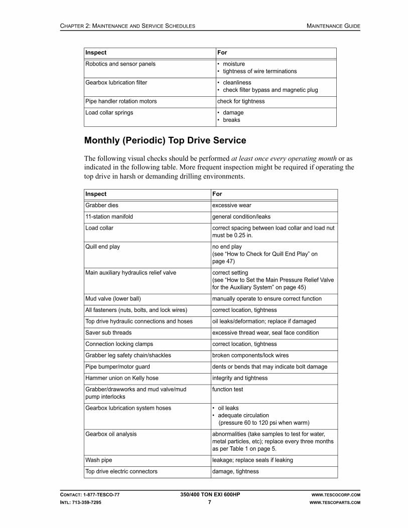
CHAPTER 2: MAINTENANCE AND SERVICE SCHEDULES MAINTENANCE GUIDE
CONTACT: 1-877-TESCO-77 350/400 TON EXI 600HP WWW.TESCOCORP.COM
INTL: 713-359-7295 7 WWW.TESCOPARTS.COM
Monthly (Periodic) Top Drive Service
The following visual checks should be performed at least once every operating month or as indicated in the following table. More frequent inspection might be required if operating the top drive in harsh or demanding drilling environments.
Robotics and sensor panels • moisture• tightness of wire terminations
Gearbox lubrication filter • cleanliness• check filter bypass and magnetic plug
Pipe handler rotation motors check for tightness
Load collar springs • damage• breaks
Inspect For
Grabber dies excessive wear
11-station manifold general condition/leaks
Load collar correct spacing between load collar and load nut must be 0.25 in.
Quill end play no end play (see “How to Check for Quill End Play” on page 47)
Main auxiliary hydraulics relief valve correct setting (see “How to Set the Main Pressure Relief Valve for the Auxiliary System” on page 45)
Mud valve (lower ball) manually operate to ensure correct function
All fasteners (nuts, bolts, and lock wires) correct location, tightness
Top drive hydraulic connections and hoses oil leaks/deformation; replace if damaged
Saver sub threads excessive thread wear, seal face condition
Connection locking clamps correct location, tightness
Grabber leg safety chain/shackles broken components/lock wires
Pipe bumper/motor guard dents or bends that may indicate bolt damage
Hammer union on Kelly hose integrity and tightness
Grabber/drawworks and mud valve/mud pump interlocks
function test
Gearbox lubrication system hoses • oil leaks• adequate circulation (pressure 60 to 120 psi when warm)
Gearbox oil analysis abnormalities (take samples to test for water, metal particles, etc); replace every three months as per Table 1 on page 5.
Wash pipe leakage; replace seals if leaking
Top drive electric connectors damage, tightness
Inspect For

MAINTENANCE GUIDE CHAPTER 2: MAINTENANCE AND SERVICE SCHEDULES
CONTACT: 1-877-TESCO-77 350/400 TON EXI 600HP WWW.TESCOCORP.COM
INTL: 713-359-7295 8 WWW.TESCOPARTS.COM
The following lubrication should be performed at least once every operating month. More frequent lubrication might be required if operating the top drive in harsh or demanding drilling environments.
IMPORTANT: This equipment was filled at the factory with TESCO ULTREX brand fluids and greases. To ensure maximum performance and to avoid cross-contamination, we strongly recommend the continued usage of TESCO ULTREX lubricants, unless otherwise specified.
Six-Month Top Drive Service
Lubrication
The following lubrication should be performed at least once every six months. More frequent lubrication might be required if operating the top drive in harsh or demanding drilling environments.
IMPORTANT: This equipment was filled at the factory with TESCO ULTREX brand fluids and greases. To ensure maximum performance and to avoid cross-contamination, we strongly recommend the continued usage of TESCO ULTREX lubricants, unless otherwise specified.
1,000 Operating Day Top Drive Service
Apart from the regular load path and gearbox inspections as defined in Chapter 3: Non-Destructive Testing and Inspection Schedules, the following shall be serviced.
Lubricate With
Hinge pins and extend frame (if applicable) spray with penetrating oil (WD 40, or spray lithium)
Main Motor/Input shaft splines TESCO ULTREX, NLGI #1 or 2
Lubricate With
Main Drive motor bearings TESCO ULTREX, NLGI #1 or 2
Slewing bearing TESCO ULTREX, NLGI #1 or 2
Inspect Action
Hoses replace all auxiliary hydraulic and lubrication system hoses

CHAPTER 2: MAINTENANCE AND SERVICE SCHEDULES MAINTENANCE GUIDE
CONTACT: 1-877-TESCO-77 350/400 TON EXI 600HP WWW.TESCOCORP.COM
INTL: 713-359-7295 9 WWW.TESCOPARTS.COM
Figure 2-1: Lubrication points for the 350T EXI 600 Top Drive

MAINTENANCE GUIDE CHAPTER 2: MAINTENANCE AND SERVICE SCHEDULES
CONTACT: 1-877-TESCO-77 350/400 TON EXI 600HP WWW.TESCOCORP.COM
INTL: 713-359-7295 10 WWW.TESCOPARTS.COM
Figure 2-2: Lubrication points for the 400T EXI 600 Top Drive

CHAPTER 2: MAINTENANCE AND SERVICE SCHEDULES MAINTENANCE GUIDE
CONTACT: 1-877-TESCO-77 350/400 TON EXI 600HP WWW.TESCOCORP.COM
INTL: 713-359-7295 11 WWW.TESCOPARTS.COM
DRILLER’S PANEL SERVICE REQUIREMENTS
Monthly Driller’s Panel Service
The following visual checks should be performed at least once every operating month. More frequent inspection might be required if operating the top drive in harsh or demanding drilling environments.
SERVICE LOOP SERVICE REQUIREMENTS
Weekly Service Loop Service
The following visual checks should be performed at least once every operating week. More frequent inspection might be required if operating the top drive in harsh or demanding drilling environments.
Monthly (Periodic) Service Loop Service
The following visual checks should be performed at least once every operating month. More frequent inspection might be required if operating the top drive in harsh or demanding drilling environments.
Inspect For
Wire terminals in the driller’s panel tightness
Versa max modules locked in place
Indication lights working
Switch contact blocks tightness
Inspect For
All service loop hoses damage, excessive wear, hardness, heat cracked or charred; replace if damaged condition occurs
Urethane capture blocks(at top drive and roller saddle)
hose placement, tightness
Fluid quick couplers (auxiliary hydraulics) damage or decay, tightness
All cable connections and cables(power, sensor, robotics, and ground cables)
damage, tightness and scuffing
Inspect For
All multi-conductor connections moisture, dirt; open and check, then spray with electrical cleaner/moisture dispersant
Main service cable connectors(power, sensor, robotics, ground cables)
cleanliness; open, clean, reinstall

MAINTENANCE GUIDE CHAPTER 2: MAINTENANCE AND SERVICE SCHEDULES
CONTACT: 1-877-TESCO-77 350/400 TON EXI 600HP WWW.TESCOCORP.COM
INTL: 713-359-7295 12 WWW.TESCOPARTS.COM
1,000 Operating Day Service Loop Service
TORQUE ARREST SYSTEM SERVICE REQUIREMENTS
Daily Torque Arrest System Service
The following visual checks should be performed at least once every operating day. More frequent inspection might be required if operating the top drive in harsh or demanding drilling environments.
Weekly Torque Arrest System Service
The following visual checks should be performed at least once every operating week. More frequent inspection might be required if operating the top drive in harsh or demanding drilling environments.
Inspect Action
Hoses replace all hoses
Inspect For
All pinned connections damage or decay/corrosion
All overhead equipment (T-bar, torque beam, torque track, torque bushing)
damage or decay/corrosion
Inspect For
All bolts and threaded rods damage or decay, tightness
Torque track hanging assembly damage; close visual inspection is required
Torque bushing liner wear (the bushing liner must be replaced before the liner mounting bolts come in contact with the torque tube)
Torque bushing clearance amount of clearance (between 1/16” to 1/4”); adjust side plates to obtain clearance as specified
Torque track stabilization components cracks or loose fasteners; close visual inspection is required
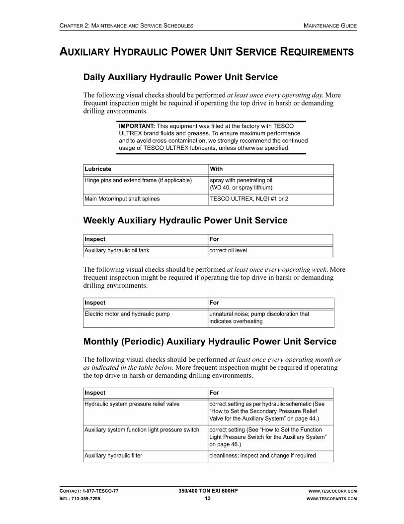
CHAPTER 2: MAINTENANCE AND SERVICE SCHEDULES MAINTENANCE GUIDE
CONTACT: 1-877-TESCO-77 350/400 TON EXI 600HP WWW.TESCOCORP.COM
INTL: 713-359-7295 13 WWW.TESCOPARTS.COM
AUXILIARY HYDRAULIC POWER UNIT SERVICE REQUIREMENTS
Daily Auxiliary Hydraulic Power Unit Service
The following visual checks should be performed at least once every operating day. More frequent inspection might be required if operating the top drive in harsh or demanding drilling environments.
IMPORTANT: This equipment was filled at the factory with TESCO ULTREX brand fluids and greases. To ensure maximum performance and to avoid cross-contamination, we strongly recommend the continued usage of TESCO ULTREX lubricants, unless otherwise specified.
Weekly Auxiliary Hydraulic Power Unit Service
The following visual checks should be performed at least once every operating week. More frequent inspection might be required if operating the top drive in harsh or demanding drilling environments.
Monthly (Periodic) Auxiliary Hydraulic Power Unit Service
The following visual checks should be performed at least once every operating month or as indicated in the table below. More frequent inspection might be required if operating the top drive in harsh or demanding drilling environments.
Lubricate With
Hinge pins and extend frame (if applicable) spray with penetrating oil (WD 40, or spray lithium)
Main Motor/Input shaft splines TESCO ULTREX, NLGI #1 or 2
Inspect For
Auxiliary hydraulic oil tank correct oil level
Inspect For
Electric motor and hydraulic pump unnatural noise; pump discoloration that indicates overheating
Inspect For
Hydraulic system pressure relief valve correct setting as per hydraulic schematic (See “How to Set the Secondary Pressure Relief Valve for the Auxiliary System” on page 44.)
Auxiliary system function light pressure switch correct setting (See “How to Set the Function Light Pressure Switch for the Auxiliary System” on page 46.)
Auxiliary hydraulic filter cleanliness; inspect and change if required

MAINTENANCE GUIDE CHAPTER 2: MAINTENANCE AND SERVICE SCHEDULES
CONTACT: 1-877-TESCO-77 350/400 TON EXI 600HP WWW.TESCOCORP.COM
INTL: 713-359-7295 14 WWW.TESCOPARTS.COM
1,000 Operating Day Auxiliary Hydraulic Power Unit Service
POWER MODULE SERVICE REQUIREMENTS
Daily Power Module Service
The following visual checks should be performed at least once every operating day. More frequent inspection might be required if operating the top drive in harsh or demanding drilling environments.
Condensation
Condensation occurs when warm, moist air comes in contact with a cold surface. If the door to the power module is left open, the cool air escapes and warm air enters. This results in conden-sation on and inside the power module cabinets.
Note: If condensation occurs in the power module, do the following:
Auxiliary hydraulic fluid complete fluid analysis; replace every six months or 250 operating days as per Table 1 on page 5
Auxiliary hydraulic hoses leaks, damage, hardness, heat cracked or charred; replace if damaged condition occurs
Inspect Action
Hoses replace all hoses
Inspect For
Drive componentsCaution: Condensation in the drive components can cause severe damage if not immediately addressed. See “Condensation” on page 14.
moisture
VFD for Blower Motor proper operation
Door fans on VFD Cabinets proper operation
Indicator lights on PLC Panel correct function (replace if required)
ESD push button correct function (replace if required)
Braking resistor module for sign of overheating, damage or decay
Inspect For
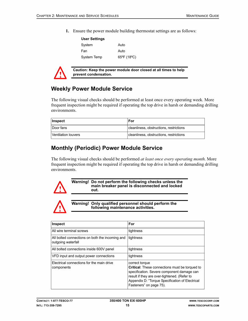
CHAPTER 2: MAINTENANCE AND SERVICE SCHEDULES MAINTENANCE GUIDE
CONTACT: 1-877-TESCO-77 350/400 TON EXI 600HP WWW.TESCOCORP.COM
INTL: 713-359-7295 15 WWW.TESCOPARTS.COM
1. Ensure the power module building thermostat settings are as follows:
Caution: Keep the power module door closed at all times to help prevent condensation.
Weekly Power Module Service
The following visual checks should be performed at least once every operating week. More frequent inspection might be required if operating the top drive in harsh or demanding drilling environments.
Monthly (Periodic) Power Module Service
The following visual checks should be performed at least once every operating month. More frequent inspection might be required if operating the top drive in harsh or demanding drilling environments.
Warning! Do not perform the following checks unless the main breaker panel is disconnected and locked out.
Warning! Only qualified personnel should perform the following maintenance activities.
User Settings
System Auto
Fan Auto
System Temp 65ºF (18ºC)
Inspect For
Door fans cleanliness, obstructions, restrictions
Ventilation louvers cleanliness, obstructions, restrictions
Inspect For
All wire terminal screws tightness
All bolted connections on both the incoming and outgoing waterfall
tightness
All bolted connections inside 600V panel tightness
VFD input and output power connections tightness
Electrical connections for the main drive components
correct torqueCritical: These connections must be torqued to specification. Severe component damage can result if they are over-tightened. (Refer to Appendix D: “Torque Specification of Electrical Fasteners” on page 75).
!
!
!

MAINTENANCE GUIDE CHAPTER 2: MAINTENANCE AND SERVICE SCHEDULES
CONTACT: 1-877-TESCO-77 350/400 TON EXI 600HP WWW.TESCOCORP.COM
INTL: 713-359-7295 16 WWW.TESCOPARTS.COM
This page has been left blank intentionally.

CHAPTER 3: NON-DESTRUCTIVE TESTING AND INSPECTION SCHEDULES MAINTENANCE GUIDE
CONTACT: 1-877-TESCO-77 350/400 TON EXI 600HP WWW.TESCOCORP.COM
INTL: 713-359-7295 17 WWW.TESCOPARTS.COM
CHAPTER 3: NON-DESTRUCTIVE TESTING AND INSPECTION SCHEDULES
TOP DRIVE OWNER’S GUIDELINES
The integrity, performance, and safe operation of TESCO’s top drives depend on sound maintenance and inspection of all load path, torque arrest system, and critical components. This chapter describes TESCO’s minimum recommended inspection schedule, including the following:
• recommended reporting format for third party inspections• recommended minimum inspection frequency for each load path, torque arrest system
or critical component• specific areas of concern for each component
Caution: In addition to the schedule suggested here, all load path, torque arrest system, and critical components must be inspected following rough drilling, excessive jarring, or any other exceptional circumstance that might increase the likelihood of fatigue failure.
When receiving inspection reports, file them in accordance with procedures in the operating area.
It is critical to maintain complete inspection and service records for all load path, torque arrest system, and other critical components.
Caution: This guide addresses MPI and WFMPI (Wet Fluorescent Magnetic Particle Inspection) testing only. This information must be used in conjunction with a regular inspection and maintenance pro-gram as defined in Chapter 2: Maintenance and Service Schedules.
TESCO will not assume responsibility or liability for any component, product or material that has been repaired, rebuilt, welded, or heat treated outside of TESCO facilities.
!
!

MAINTENANCE GUIDE CHAPTER 3: NON-DESTRUCTIVE TESTING AND INSPECTION SCHEDULES
CONTACT: 1-877-TESCO-77 350/400 TON EXI 600HP WWW.TESCOCORP.COM
INTL: 713-359-7295 18 WWW.TESCOPARTS.COM
GUIDELINES FOR COMPONENT INSPECTORS
Only qualified personnel can inspect load path, torque arrest system, and critical components. Inspectors must use only fully operational, regularly maintained testing equipment. To ensure accurate test results, each component must be thoroughly cleaned before inspection. In some cases removal of paint is required.
If inspecting a TESCO load path, torque arrest system, or critical component, the top drive owner must be provided with the following information.
General information for each component tested:
• type of test or inspection performed (MPI, WFMPI, etc.)• type of equipment used to perform the testing• operating conditions• name and type of inspecting company• name and signature of the inspector• date of inspection
Inspection results for each component tested:
• part description (name, size, etc.)• serial number of the inspected part• exact location of all points of damage (measured from a recognizable point of reference)
including the following:• cracks• excessive wear• deformation• corrosion• erosion
• all dimensions for all cracks (length, depth, width)• a photograph or illustration indicating all cracks or damage points• confirmation that all indicated inspection areas have been checked
LOAD PATH COMPONENTS AND INSPECTION INFORMATION
This chapter contains illustrations of all components in the top drive load path. Each illustra-tion indicates the inspection points for the specific component. It also describes any special considerations that must be addressed when inspecting the component.
It is critical that all components of the load path be subjected to periodic magnetic particle inspection (MPI) by a qualified inspector. Each piece should be inspected for surface defects according to the schedules that follow. MPI inspections shall be done in accordance with API 8C (latest revision).
Note: Any part of an operating day should be considered one day. Removal of paint might be required for inspection.

CHAPTER 3: NON-DESTRUCTIVE TESTING AND INSPECTION SCHEDULES MAINTENANCE GUIDE
CONTACT: 1-877-TESCO-77 350/400 TON EXI 600HP WWW.TESCOCORP.COM
INTL: 713-359-7295 19 WWW.TESCOPARTS.COM
Inspection Types
The three inspection types are outlined in Table 3-1.
Table 3-1: Inspection types
Inspection Type Description
A Visually inspect for:• wear• deformation• cracks• corrosion• galling• heat damage• other irregularities
If a crack is suspected, perform local paint strip and MPI inspection. All cracked components should be referred to TESCO Engineering for disposition.
B Perform MPI or WFMPI for cracks. All cracked components should be referred to TESCO Engineering for disposition.
C Return to a TESCO authorized service center for complete dimensional, visual, WFMPI/MPI inspection for recertification.
Upon completion of Type C inspection, the inspection schedule starts at zero operating days.
Figure 3-1: Yoke and link assembly (350 EXI 600)

MAINTENANCE GUIDE CHAPTER 3: NON-DESTRUCTIVE TESTING AND INSPECTION SCHEDULES
CONTACT: 1-877-TESCO-77 350/400 TON EXI 600HP WWW.TESCOCORP.COM
INTL: 713-359-7295 20 WWW.TESCOPARTS.COM
Figure 3-2: Yoke and Link assembly (400 EXI 600)
Point NameFrequency (Operating Days) and Inspection Type*
At 250 At 500 At 750 At 1000
1 Hook contact point A,B A,B A,B C
2 Swivel yoke A A A C
3 Swivel yoke pin holes A,B A,B A,B C
4 Yoke pins A,B A,B A,B C
5 Swivel links A A A C
6 Swivel link, yoke pin bores A,B A,B A,B C
7 Swivel link, swivel pin bores A,B A,B A,B C
*Refer to Table 3-1 on page 19 for inspection type details

CHAPTER 3: NON-DESTRUCTIVE TESTING AND INSPECTION SCHEDULES MAINTENANCE GUIDE
CONTACT: 1-877-TESCO-77 350/400 TON EXI 600HP WWW.TESCOCORP.COM
INTL: 713-359-7295 21 WWW.TESCOPARTS.COM
Figure 3-3: Swivel gearbox housing (EXI 600)
Point NameFrequency (Operating Days) and Inspection Type*
At 250 At 500 At 750 At 1000
1 Swivel gearbox housing A A A C
2 Swivel gearbox pin holes A,B A,B A,B C
3 Swivel gearbox pins A,B A,B A,B C
*Refer to Table 3-1 on page 19 for inspection type details

MAINTENANCE GUIDE CHAPTER 3: NON-DESTRUCTIVE TESTING AND INSPECTION SCHEDULES
CONTACT: 1-877-TESCO-77 350/400 TON EXI 600HP WWW.TESCOCORP.COM
INTL: 713-359-7295 22 WWW.TESCOPARTS.COM
Figure 3-4: Quill (EXI 600)
Point NameFrequency (Operating Days) and Inspection Type*
Every 60 At 250 At 500 At 750 At 1000
1 Threads on the lower gland nut and bore
— A A A C
2 Upper thrust surface — — — — C
3 Lower thrust surface — — — — C
4 Load nut grooves — A,B A,B A,B C
5 Quill pin end A,B — — — C
*Refer to Table 3-1 on page 19 for inspection type details

CHAPTER 3: NON-DESTRUCTIVE TESTING AND INSPECTION SCHEDULES MAINTENANCE GUIDE
CONTACT: 1-877-TESCO-77 350/400 TON EXI 600HP WWW.TESCOCORP.COM
INTL: 713-359-7295 23 WWW.TESCOPARTS.COM
Figure 3-5: Load nut components (EXI 600)
Point NameFrequency (Operating Days) and Inspection Type*
Every 60 At 250 At 500 At 750 At 1000
1 Upper load nut retainer — A,B A,B A,B C
2 Load nut split collar — A,B A,B A,B C
3 Load nut sleeve — A,B A,B A,B C
4 Lower load nut retainer — A A A C
5 Bolts — A A A Replace
*Refer to Table 3-1 on page 19 for inspection type details

MAINTENANCE GUIDE CHAPTER 3: NON-DESTRUCTIVE TESTING AND INSPECTION SCHEDULES
CONTACT: 1-877-TESCO-77 350/400 TON EXI 600HP WWW.TESCOCORP.COM
INTL: 713-359-7295 24 WWW.TESCOPARTS.COM
Figure 3-6: Mudsaver valve and actuator (EXI 600)
Point NameFrequency (Operating Days) and Inspection Type*
Every 60 At 250 At 500 At 750 At 1000
1 Top box connection A,B — — — C
2 Upper valve stem hole A,B — — — C
3 Lower valve stem hole A,B — — — C
4 Lower box connection A,B — — — C
5 Length of valve body A,B — — — C
*Refer to Table 3-1 on page 19 for inspection type details
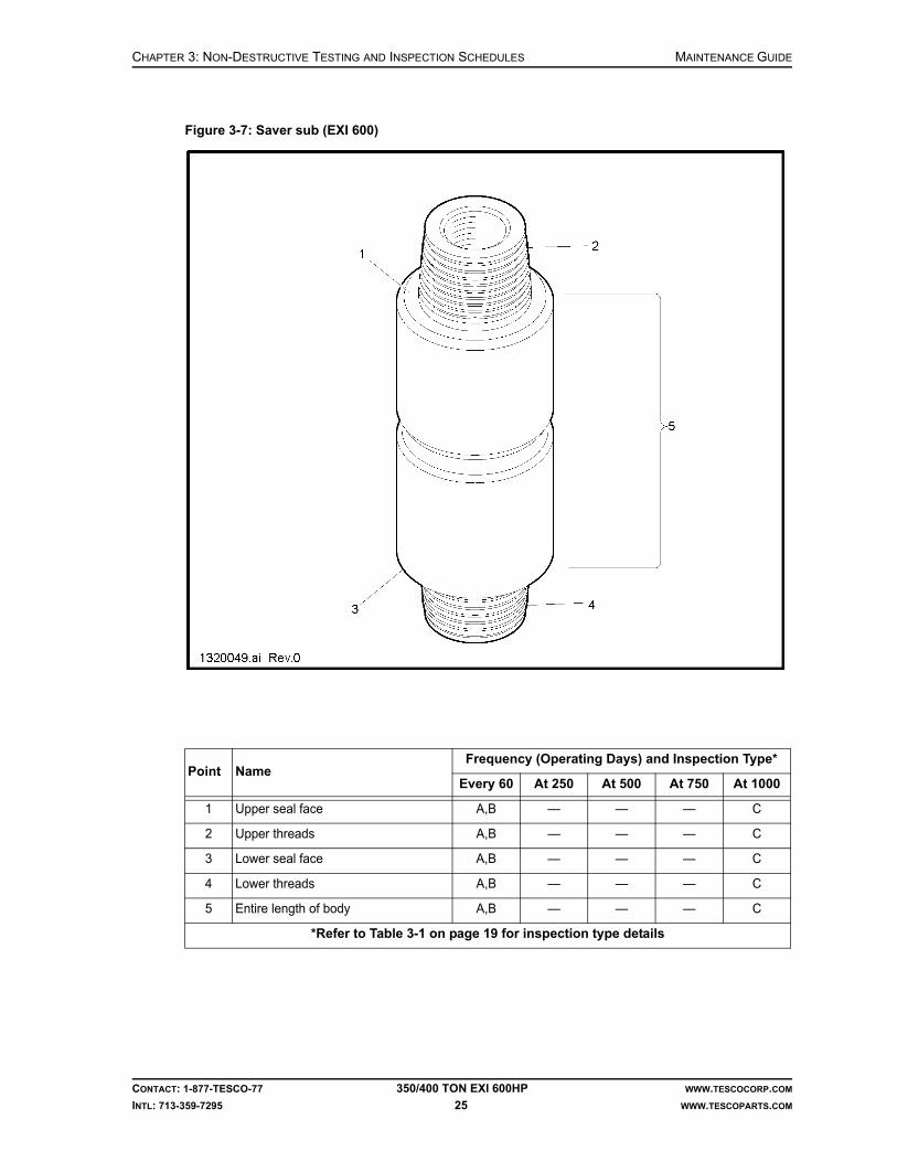
CHAPTER 3: NON-DESTRUCTIVE TESTING AND INSPECTION SCHEDULES MAINTENANCE GUIDE
CONTACT: 1-877-TESCO-77 350/400 TON EXI 600HP WWW.TESCOCORP.COM
INTL: 713-359-7295 25 WWW.TESCOPARTS.COM
Figure 3-7: Saver sub (EXI 600)
Point NameFrequency (Operating Days) and Inspection Type*
Every 60 At 250 At 500 At 750 At 1000
1 Upper seal face A,B — — — C
2 Upper threads A,B — — — C
3 Lower seal face A,B — — — C
4 Lower threads A,B — — — C
5 Entire length of body A,B — — — C
*Refer to Table 3-1 on page 19 for inspection type details

MAINTENANCE GUIDE CHAPTER 3: NON-DESTRUCTIVE TESTING AND INSPECTION SCHEDULES
CONTACT: 1-877-TESCO-77 350/400 TON EXI 600HP WWW.TESCOCORP.COM
INTL: 713-359-7295 26 WWW.TESCOPARTS.COM
Figure 3-8: Load collar (EXI 600)
Point NameFrequency (Operating Days) and Inspection Type*
Every 60 At 250 At 500 At 750 At 1000
1 Load collar ears A A,B A,B A,B C
2 Load nut, load shoulder — A,B A,B A,B C
3 Bronze bushing — — — — C
4 Inner barrel(below the bronze bushing)
— — — — C
*Refer to Table 3-1 on page 19 for inspection type details

CHAPTER 3: NON-DESTRUCTIVE TESTING AND INSPECTION SCHEDULES MAINTENANCE GUIDE
CONTACT: 1-877-TESCO-77 350/400 TON EXI 600HP WWW.TESCOCORP.COM
INTL: 713-359-7295 27 WWW.TESCOPARTS.COM
Figure 3-9: Elevator links (bails) (EXI 600)
Point NameFrequency (Operating Days) and Inspection Type*
Every 250 At 1000
1 Entire length of link A,B** C
2 Top eye (load collar eye) A,B** C
3 Bottom eye (elevator eye) A,B** C
4 Length between the eyes A,B** C
*Refer to Table 3-1 on page 19 for inspection type details**As recommended by the equipment manufacturer

MAINTENANCE GUIDE CHAPTER 3: NON-DESTRUCTIVE TESTING AND INSPECTION SCHEDULES
CONTACT: 1-877-TESCO-77 350/400 TON EXI 600HP WWW.TESCOCORP.COM
INTL: 713-359-7295 28 WWW.TESCOPARTS.COM
Figure 3-10: Elevators (EXI 600)
Point NameFrequency (Operating Days) and Inspection Type*
At 250
1 Main hinge pin C**
2 Primary latch C**
3 Secondary latch C**
4 Elevator link ears C**
5 Elevator body C**
6 Latch pins C**
7 Elevator inserts C**
8 Insert grooves (top and bottom)(Ensure the insert does not fall out)
C**
*Refer to Table 3-1 on page 19 for inspection type details**As recommended by the equipment manufacturer

CHAPTER 3: NON-DESTRUCTIVE TESTING AND INSPECTION SCHEDULES MAINTENANCE GUIDE
CONTACT: 1-877-TESCO-77 350/400 TON EXI 600HP WWW.TESCOCORP.COM
INTL: 713-359-7295 29 WWW.TESCOPARTS.COM
THREADED CONNECTIONS
All threaded connections listed in the following table must be subjected periodically to wet fluorescent magnetic particle inspection (WFMPI) by a qualified inspector. Each piece should be inspected for surface defects. Also, an inspection of threads should be conducted in accordance with the following schedule.
Note: Any part of an operating day should be considered one day.
Caution: All inspections listed in the following table should be performed following any episode of rough drilling, excessive jarring or any other exceptional circumstance that might increase the likelihood of fatigue failure. Operator discretion is critical in determining when this testing should occur.
Threaded Connection Inspection Frequency (EXI 600)
TORQUE ARREST SYSTEM
All components of the torque arrest system must be subjected to periodic magnetic particle inspection (MPI) by a qualified inspector. Each piece should be inspected for surface defects according to the following schedule.
Any part of an operating day should be considered one day. Removal of paint may be required for inspection.
Description Minimum Frequency* Inspection Type
Mud saver/stabbing valve(box X box, connections)
60 operating days WFMPI
Saver sub(pin X pin, connections)
60 operating days(lower threads and seal face require daily visual inspection)
WFMPI
*Frequency = the number of operating days
!

MAINTENANCE GUIDE CHAPTER 3: NON-DESTRUCTIVE TESTING AND INSPECTION SCHEDULES
CONTACT: 1-877-TESCO-77 350/400 TON EXI 600HP WWW.TESCOCORP.COM
INTL: 713-359-7295 30 WWW.TESCOPARTS.COM
Figure 3-11: Non-destructive testing for the standard torque arrest system (EXI 600)

CHAPTER 3: NON-DESTRUCTIVE TESTING AND INSPECTION SCHEDULES MAINTENANCE GUIDE
CONTACT: 1-877-TESCO-77 350/400 TON EXI 600HP WWW.TESCOCORP.COM
INTL: 713-359-7295 31 WWW.TESCOPARTS.COM
Point Name
Frequency (Operating Days) and Inspection Type*
At250
At500
At750
At1000
1 Torque bushing side plates A A A C
2 Torque bushing front plate A A A C
3 Extend frame A A,B A C
4 Redi-rod nuts (torque arrest system) A A A Replace
5 Torque beam clamp bars A A A C
6 Torque track studs/nuts — — — Replace
7 Torque track connectors A A A C
8 Torque track A A A C
9 Torque bushing bolts/nuts — — — Replace
10 Extend arms A A,B A C
11 Torque anchor beam A A A C
12 T-bar clamp plate and bolts A A A C
13 T-bar/torque track bolts A A A Replace
14 T-bar A A,B A C
15 Extend frame mounts A A A C
16 Extend frame bolts A A A Replace
17 Torque track mounting plate on bottom section; include all bolt holes
A A,B A C
T-bar extension (if applicable) A A A C
*Refer to Table 3-1 on page 19 for inspection type details

MAINTENANCE GUIDE CHAPTER 3: NON-DESTRUCTIVE TESTING AND INSPECTION SCHEDULES
CONTACT: 1-877-TESCO-77 350/400 TON EXI 600HP WWW.TESCOCORP.COM
INTL: 713-359-7295 32 WWW.TESCOPARTS.COM
PIPE HANDLER ROTATION SYSTEM INSPECTION FREQUENCY
Figure 3-12: Non-destructive inspection of PH-rotation system components (EXI 600)
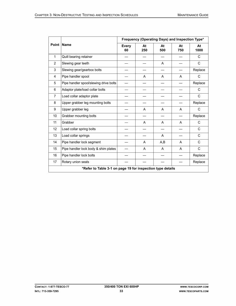
CHAPTER 3: NON-DESTRUCTIVE TESTING AND INSPECTION SCHEDULES MAINTENANCE GUIDE
CONTACT: 1-877-TESCO-77 350/400 TON EXI 600HP WWW.TESCOCORP.COM
INTL: 713-359-7295 33 WWW.TESCOPARTS.COM
Point Name
Frequency (Operating Days) and Inspection Type*
Every60
At250
At500
At750
At1000
1 Quill bearing retainer — — — — C
2 Slewing gear teeth — — A — C
3 Slewing gear/gearbox bolts — — — — Replace
4 Pipe handler spool — A A A C
5 Pipe handler spool/slewing drive bolts — — — — Replace
6 Adaptor plate/load collar bolts — — — — C
7 Load collar adaptor plate — — — — C
8 Upper grabber leg mounting bolts — — — — Replace
9 Upper grabber leg — A A A C
10 Grabber mounting bolts — — — — Replace
11 Grabber — A A A C
12 Load collar spring bolts — — — — C
13 Load collar springs — — A — C
14 Pipe handler lock segment — A A,B A C
15 Pipe handler lock body & shim plates — A A A C
16 Pipe handler lock bolts — — — — Replace
17 Rotary union seals — — — — Replace
*Refer to Table 3-1 on page 19 for inspection type details

MAINTENANCE GUIDE CHAPTER 3: NON-DESTRUCTIVE TESTING AND INSPECTION SCHEDULES
CONTACT: 1-877-TESCO-77 350/400 TON EXI 600HP WWW.TESCOCORP.COM
INTL: 713-359-7295 34 WWW.TESCOPARTS.COM
GEARBOX INSPECTION FREQUENCYFigure 3-13: Inspection of gearbox (EXI 600)

CHAPTER 3: NON-DESTRUCTIVE TESTING AND INSPECTION SCHEDULES MAINTENANCE GUIDE
CONTACT: 1-877-TESCO-77 350/400 TON EXI 600HP WWW.TESCOCORP.COM
INTL: 713-359-7295 35 WWW.TESCOPARTS.COM
All load path equipment on the top drive must be inspected at regular intervals. The extent and schedule of these inspections are detailed in this chapter. The most rigorous inspection must take place every 1,000 operating days and include a complete tear down of the top drive. During this 1,000 operating day tear down, the following inspections and replacements must be done on the gearbox components (refer to Figure 3-13 on page 34):
Point NameFrequency (Operating Days) and Inspection Type*
At 250 At 500 At 750 At 1000
1 Upper quill bearing — — — Replace
2 Lower quill bearing — — — Replace
3 Thrust bearing — — — Replace
4 Upper intermediate shaft bearing — — — Replace
5 Lower intermediate shaft bearing — — — Replace
6 Upper input pinion bearing — — — Replace
7 Lower input pinion bearing — — — Replace
8 600hp motor bearings — — — Replace
9 Blower motor bearings — — — Replace
10 Bull gear — — — A,B
11 Intermediate bull gear — — — A,B
12 Intermediate pinion — — — A,B
13 Input pinion — — — A,B
14 Upper quill bearing seals — — — Replace
15 Lower quill bearing seals — — — Replace
16 Upper input pinion seal — — — Replace
17 Lower input pinion seal — — — Replace
18 Mud shield — A — A
19 All O-rings — — — Replace
20 Lubrication hoses A A A Replace
21 Auxiliary hydraulic hoses A A A Replace
*Refer to Table 3-1 on page 19 for inspection type details

MAINTENANCE GUIDE CHAPTER 3: NON-DESTRUCTIVE TESTING AND INSPECTION SCHEDULES
CONTACT: 1-877-TESCO-77 350/400 TON EXI 600HP WWW.TESCOCORP.COM
INTL: 713-359-7295 36 WWW.TESCOPARTS.COM
This page has been left blank intentionally.

CHAPTER 4: SERVICE PROCEDURES MAINTENANCE GUIDE
CONTACT: 1-877-TESCO-77 350/400 TON EXI 600HP WWW.TESCOCORP.COM
INTL: 713-359-7295 37 WWW.TESCOPARTS.COM
CHAPTER 4: SERVICE PROCEDURES
INTRODUCTION
The service procedures described in this chapter are an extension of the service activities discussed in Chapter 2: Maintenance and Service Schedules.

MAINTENANCE GUIDE CHAPTER 4: SERVICE PROCEDURES
CONTACT: 1-877-TESCO-77 350/400 TON EXI 600HP WWW.TESCOCORP.COM
INTL: 713-359-7295 38 WWW.TESCOPARTS.COM
Figure 4-1: General maintenance areas (350 EXI 600)

CHAPTER 4: SERVICE PROCEDURES MAINTENANCE GUIDE
CONTACT: 1-877-TESCO-77 350/400 TON EXI 600HP WWW.TESCOCORP.COM
INTL: 713-359-7295 39 WWW.TESCOPARTS.COM
Figure 4-2: General maintenance areas (400 EXI 600)
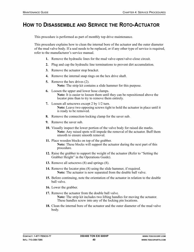
MAINTENANCE GUIDE CHAPTER 4: SERVICE PROCEDURES
CONTACT: 1-877-TESCO-77 350/400 TON EXI 600HP WWW.TESCOCORP.COM
INTL: 713-359-7295 40 WWW.TESCOPARTS.COM
HOW TO DISASSEMBLE AND SERVICE THE ROTO-ACTUATOR
This procedure is performed as part of monthly top drive maintenance.
This procedure explains how to clean the internal bore of the actuator and the outer diameter of the mud valve body. If a seal needs to be replaced, or if any other type of service is required, refer to the manufacturer’s service manual.
1. Remove the hydraulic lines for the mud valve-open/valve-close circuit.
2. Plug and cap the hydraulic line terminations to prevent dirt accumulation.
3. Remove the actuator stop bracket.
4. Remove the internal snap rings on the hex drive shaft.
5. Remove the hex drives (2).Note: The strip kit contains a slide hammer for this purpose.
6. Loosen the upper and lower hose clamps.Note: It is easier to loosen them until they can be repositioned above the locator pins than to try to remove them entirely.
7. Loosen all setscrews except 2 by 1/2 turn.Note: Leave two opposing screws tight to hold the actuator in place until it is ready to be removed.
8. Remove the connection-locking clamp for the saver sub.
9. Remove the saver sub.
10. Visually inspect the lower portion of the valve body for raised die marks.Note: Any raised spots will impede the removal of the actuator. Buff them smooth to ensure smooth removal.
11. Place wooden blocks on top of the grabber.Note: These blocks will support the actuator during the next part of this procedure.
12. Raise the grabber to support the weight of the actuator (Refer to “Setting the Grabber Height” in the Operations Guide).
13. Remove all setscrews (8) and springs (8).
14. Remove the locator pins (8) using the slide hammer, if required.Note: The actuator is now separated from the double ball valve.
15. Before continuing, note the orientation of the actuator in relation to the double ball valve.
16. Lower the grabber.
17. Remove the actuator from the double ball valve.Note: The strip kit includes two lifting handles for moving the actuator. These handles screw into any of the locking pin locations.
18. Clean the internal bore of the actuator and the outer diameter of the mud valve body.

CHAPTER 4: SERVICE PROCEDURES MAINTENANCE GUIDE
CONTACT: 1-877-TESCO-77 350/400 TON EXI 600HP WWW.TESCOCORP.COM
INTL: 713-359-7295 41 WWW.TESCOPARTS.COM
Re-assembly
1. Lightly grease the internal bore of the actuator and the outer diameter of the mud valve body.
IMPORTANT: This equipment was filled at the factory with TESCO ULTREX brand fluids and greases. To ensure maximum performance and to avoid cross-contamination, we strongly recommend the continued usage of TESCO ULTREX lubricants, unless otherwise specified.
2. Position the actuator on top of the wooden blocks, on the grabber.
3. Ensure that the actuator and valve are either both open, or both closed.
4. Align the valve sockets on the actuator with the valve sockets on the valve. See Figure 4-3.
Danger! If the orientation is not correct, the valve will not open when required. This causes a serious safety hazard.
5. Slowly raise the grabber to move the actuator to the correct position. The actuator should slide smoothly onto the double ball valve.
6. Install four brass shims between the body of the mud valve and the actuator.Note: The shims help to align the valve and actuator concentrically during assembly.
7. Coat all locking pins and setscrews with a thin coat of anti-seize compound.
Figure 4-3: Actuator/valve orientation
Align the valve sockets before sliding the actuator over the valve.
!

MAINTENANCE GUIDE CHAPTER 4: SERVICE PROCEDURES
CONTACT: 1-877-TESCO-77 350/400 TON EXI 600HP WWW.TESCOCORP.COM
INTL: 713-359-7295 42 WWW.TESCOPARTS.COM
8. Install the locking pins, springs and setscrews as follows:
a. Put all locking pins, spring and setscrews in place.
b. Turn the setscrews until they meet the springs, but do not tighten them.
c. Start the locking pins.
9. Install the hex drives (2).
10. Install the snap rings into snap ring grooves.
11. Tighten all setscrews, evenly, to 100 ft-lb (136 N-m).
12. Install a hose clamp over the locking pins.
13. Remove the brass centering shims.
14. Lower the grabber.
15. Remove the wooden blocks.
16. Rotate the quill with the top drive to position the locking mechanism to accept the stop bracket of the actuator.
17. Install the stop bracket.
18. Connect the hydraulic lines for the mud valve-open/valve-close circuit.
19. Test the actuator to confirm that it is working correctly.
HOW TO SET THE COUNTER-BALANCE CUSHION HEIGHT
The following conditions must exist before the following portion of the counter-balance installation can be completed.
• The top drive must be installed.• The hydraulic circuit must be connected.• The driller’s panel must be operational.• The top drive must be positioned at the racking platform.
1. Connect the hose quick-coupler for the elevator to the charge fitting for the counter-balance system.
2. Shut off the auxiliary pump.
3. Open the needle valve on the counter-balance charge hose.
4. Set the ELEVATOR switch (at the driller’s panel) to ‘OPEN’, push and hold the ELEVATOR SAFETY–OPEN button.
Note: This allows the hydraulic fluid to drain from the counter balance circuit.
5. Check the nitrogen pressure, and adjust to 1,200 psi (8.3 MPa) if required.
6. Ensure the counter-balance relief valve is set at 1,800 psi (12.4 MPa).Note: The relief valve on the CE/ATEX certified units are preset and cannot be adjusted.
7. Close the needle valve on the counter-balance charge hose
8. Start the auxiliary pump.
9. Set the ELEVATOR switch (driller’s panel) to ‘CLOSE’.Note: This will send 1,500 psi (10.3 MPa) hydraulic pressure to the needle valve on the counter-balance manifold.

CHAPTER 4: SERVICE PROCEDURES MAINTENANCE GUIDE
CONTACT: 1-877-TESCO-77 350/400 TON EXI 600HP WWW.TESCOCORP.COM
INTL: 713-359-7295 43 WWW.TESCOPARTS.COM
10. Slowly open the needle valve and allow the hydraulic oil to charge the counter-balance system.
11. Monitor the counter-balance cushion by watching the gap that develops between the yoke pin and the top of the swivel link bore, refer to Figure 4-4 on page 43.
12. Continue to charge the system until the gap is 1-1/2 in. to 2 in.
13. Close the needle valve.
14. Shut off the auxiliary pump.Note: This will allow the oil pressure in the auxiliary system to decrease.
15. Set the ELEVATOR switch to ‘OPEN’, then to ‘CLOSE’. This will relieve any pressure in the system.
16. Remove the elevator hydraulic hose from the counter-balance manifold.
Caution: If disconnecting a quick coupler while there is pressure in the system, it will be extremely difficult to reconnect the coupler.
Figure 4-4: Counter-balance cushion height (350 EXI 600)
!

MAINTENANCE GUIDE CHAPTER 4: SERVICE PROCEDURES
CONTACT: 1-877-TESCO-77 350/400 TON EXI 600HP WWW.TESCOCORP.COM
INTL: 713-359-7295 44 WWW.TESCOPARTS.COM
HOW TO SET THE SECONDARY PRESSURE RELIEF VALVE FOR THE AUXILIARY SYSTEM
The main pressure relief valve is located on the 10-station manifold of the top drive. However, a secondary relief valve is located on the auxiliary power unit. The secondary relief valve must be set first. It must be set 200 psi higher than the main pressure relief valve. Follow the proce-dure described below to set the secondary pressure relief valves.
1. Disconnect the auxiliary hydraulic service loop from the power unit or at the top drive.
2. Loosen the lock nut on the relief valve at the power unit and back out the adjustment screw to the maximum.
3. Start the auxiliary pump by setting the AUX PUMP switch (at the driller’s panel) to ‘ON’.
4. The hydraulic oil will now flow over the relief valve.
5. Slowly turn the adjustment screw until the pressure gauge on the power unit indicates the desired pressure (it should be 200 psi (1.4 MPa) higher than the value the main pressure relief valve needs to be set to).
6. Set the AUX PUMP switch to ‘OFF’.
7. Tighten the lock nut on the relief valve.
8. Switch on the auxiliary pump and confirm the pressure setting on the pressure gauge.
Figure 4-5: Counter-balance cushion height (400 EXI 600)

CHAPTER 4: SERVICE PROCEDURES MAINTENANCE GUIDE
CONTACT: 1-877-TESCO-77 350/400 TON EXI 600HP WWW.TESCOCORP.COM
INTL: 713-359-7295 45 WWW.TESCOPARTS.COM
9. Switch off the auxiliary pump and open the bypass valve to relieve the pressure; refer to Figure 4-7 on page 46.
10. Connect the auxiliary hydraulic service loop.
11. The secondary relief valve is now set.
HOW TO SET THE MAIN PRESSURE RELIEF VALVE FOR THE AUXILIARY SYSTEM
The main pressure relief valve is located on the 10-station manifold of the top drive. Follow the procedure described below to set the main pressure relief valve.
Note: This procedure applies only to standard CSA units. It does not apply to the CE/ATEX certified units because the main pressure relief valve on the CE/ATEX certified units are preset and cannot be adjusted.
Note: Before the main pressure relief valve is set, ensure the secondary pressure relief valve (located on the auxiliary power unit) is set as per the procedure described in the previous section “How to Set the Secondary Pressure Relief Valve for the Auxiliary System” on page 44.
Figure 4-6: Auxiliary system main pressure relief valve
1. Locate the main pressure relief valve on the top drive (see “Figure 4-6: Auxiliary system main pressure relief valve”).
2. Loosen the lock nut on the main relief valve adjustment screw and back out the adjustment screw to its maximum.

MAINTENANCE GUIDE CHAPTER 4: SERVICE PROCEDURES
CONTACT: 1-877-TESCO-77 350/400 TON EXI 600HP WWW.TESCOCORP.COM
INTL: 713-359-7295 46 WWW.TESCOPARTS.COM
3. Start the auxiliary pump by setting the AUX PUMP switch (at the driller’s panel) to ‘ON’.
4. Set the PIPE HANDLER LOCK switch to ‘LOCK’. The auxiliary hydraulic system is now dead headed and the hydraulic oil will flow over the main relief valve.
5. Slowly turn the adjustment screw on the relief valve until the auxiliary pressure gauge on the top drive indicates the desired pressure (the desired pressure setting of the relief valve is listed on the applicable hydraulic schematic drawing).
6. Tighten the lock nut.
7. Set the PIPE HANDLER LOCK switch to neutral.
8. After a few seconds, set the PIPE HANDLER LOCK switch again to ‘LOCK’.
9. Confirm the pressure setting on the pressure gauge.
10. Set the PIPE HANDLER LOCK switch to neutral.
11. Set the AUX PUMP switch to ‘OFF’.
12. The main relief valve is now set.
HOW TO SET THE FUNCTION LIGHT PRESSURE SWITCH FOR THE AUXILIARY SYSTEM
Perform this procedure as part of the monthly auxiliary hydraulic power unit maintenance.
Note: The function light pressure switch for the auxiliary system should be set to 800 psi (5.5 MPa). It is easier if two people perform this procedure.
1. Ensure the auxiliary pump is shut off.
2. Disconnect the pressure line to the top drive.Note: The quick coupler is located at the auxiliary hydraulic power unit.
3. Open the bypass ball valve for the auxiliary system.Note: This ball valve is located between the pressure line and the return quick-couplers at the auxiliary hydraulic power unit.
Figure 4-7: Auxiliary hydraulic system schematic
1. Quick coupler2. Return auxiliary hydraulic line3. By-pass ball valve4. Supply auxiliary hydraulic line5. Oil reservoir

CHAPTER 4: SERVICE PROCEDURES MAINTENANCE GUIDE
CONTACT: 1-877-TESCO-77 350/400 TON EXI 600HP WWW.TESCOCORP.COM
INTL: 713-359-7295 47 WWW.TESCOPARTS.COM
4. Set the AUX PUMP switch to ‘ON’.
5. Slowly close the ball valve to raise the pressure to 700 psi (4.8 MPa).Note: Pressure is indicated on the adjacent pressure gauge.
6. Use the adjustment wheel on the pressure switch to adjust the pressure until the AUX PUMP ‘ON’ indicator light on the driller’s panel illuminates.
Note: Someone might need to stand at the driller’s panel to monitor the light. If no assistance is available, use a digital multi-meter as follows:
a. Attach the black lead to terminal PSP-1 (wire #2) and the red lead to the output side of the pressure switch, terminal PSP-3 (wire #407).
b. Adjust the pressure switch.
c. When the meter rises to 24V nominal, the indicator light is illuminated.
7. Set the AUX PUMP switch to ‘OFF’.
8. Reconnect the pressure line to the top drive.
9. Close the bypass ball valve for the auxiliary system.
10. Operate any hydraulic function to confirm that the indicator light is operating correctly.
HOW TO CHECK AND ADJUST PRELOAD FOR THE QUILL UPPER BEARING
When the top drive is manufactured, TESCO adjusts the preload for the quill upper bearing by placing a shim pack between the top bearing retainer and the gearbox.
When the retainer bolts on the top bearing are torqued, this exerts a clamping force on the quill upper bearing and thrust bearing. This force prevents the quill from exhibiting end play during operation of the top drive. Preload is measured in 0.000 of an inch. The ideal preload is 0.005 to 0.007 in.
Over time, bearing and component wear will reduce the preload. If the preload is reduced too much, quill end play will result. Even the smallest amount of end play will result in damage to the bearings and mating components.
For this reason, quill end play should be checked every month, or after any severe operating events such as jarring or rough drilling.
How to Check for Quill End Play
1. Remove the washpipe.
2. Install a heavy wooden block across the grabber box.
3. Attach the magnetic base of a dial gauge to the top surface of the quill.
4. Position the dial needle on the bearing retainer.
5. Set the dial gauge to zero.

MAINTENANCE GUIDE CHAPTER 4: SERVICE PROCEDURES
CONTACT: 1-877-TESCO-77 350/400 TON EXI 600HP WWW.TESCOCORP.COM
INTL: 713-359-7295 48 WWW.TESCOPARTS.COM
6. Position a jack on top of the block on the grabber.
7. Install a protective plate between the jack and the quill.
8. With the quill plate in position, use a jack to lift the quill upward.
9. Monitor the dial gauge for any sign of movement.Note: Any movement of the dial gauge indicates that there is quill end play.
10. To ensure that an accurate reading of quill movement is obtained, perform steps 8 and 7 again.
How to Calculate the Preload Adjustment
If the previous procedure reveals any amount of quill end play, the quill preload must be adjusted. To decrease end play in the quill (increase the preload), the shims must be removed from the shim pack. Use the following calculation to determine how many shims to remove.
observed quill end play (in 0.000 in.) + 0.005 in. = the thickness of shims to be removed
Sample Calculation
If the quill end play is 0.019 in., then 0.019 in. + 0.005 in. = 0.024 in. (+0.002/ -0.000)
Between 0.024 to 0.026 in. of shims must be removed to adjust the preload to the correct force.
Figure 4-8: Measure the quill hub endplay

CHAPTER 4: SERVICE PROCEDURES MAINTENANCE GUIDE
CONTACT: 1-877-TESCO-77 350/400 TON EXI 600HP WWW.TESCOCORP.COM
INTL: 713-359-7295 49 WWW.TESCOPARTS.COM
How to Adjust the Preload
It is important to keep all components clean and free of grit and debris. Ensure that the working area is clean before performing this procedure.
1. Remove the washpipe and bonnet.
2. Remove all upper bearing retainer bolts.
3. Thread two long 5/8”-11 UNC bolts into the retainer bolt holes (these are used as alignment pins).
4. Install three lifting eyes into threaded holes.
5. Using a chain fall or other lifting device, remove the quill retainer to allow access to the shim pack.
6. Remove the required shims from the shim pack.Note: Shim packs typically contain 0.010 in., 0.005 in., and 0.002 in. shims. Remove the shims to achieve a preload of 0.005 to 0.007 in. If required, shims are available from TESCO.
7. Use a chain fall or other lifting device to lower the bearing retainer back into position.
8. Remove the alignment pins.
9. Replace all upper bearing retainer bolts.Note: To check preload again, replace every second retainer bolt and retest according the procedure “How to Check for Quill End Play” on page 47.
Figure 4-9: Preload adjustment

MAINTENANCE GUIDE CHAPTER 4: SERVICE PROCEDURES
CONTACT: 1-877-TESCO-77 350/400 TON EXI 600HP WWW.TESCOCORP.COM
INTL: 713-359-7295 50 WWW.TESCOPARTS.COM
This page has been left blank intentionally.

CHAPTER 5: DISASSEMBLY AND ASSEMBLY INSTRUCTIONS MAINTENANCE GUIDE
CONTACT: 1-877-TESCO-77 350/400 TON EXI 600HP WWW.TESCOCORP.COM
INTL: 713-359-7295 51 WWW.TESCOPARTS.COM
CHAPTER 5: DISASSEMBLY AND ASSEMBLY INSTRUCTIONS
Install the Mudsaver Valve
1. Apply pipe dope to the mudsaver valve and quill pin.
2. Lift the mudsaver valve and place it on the grabber.
Caution: The bottom of the valve will extend through the grabber box. Do not close the grabber.
Note: The valve actuator can be put on blocks. This will raise the valve actua-tor so that it can easily connect to the quill.
3. At the driller’s panel, set the MODE switch to ‘DRILL’, and set the QUILL switch to ‘FWD’.
4. Set the TORQUE value to approximately 5,500 ft-lb/7,458 N-m (10% of the make up torque for an NC61 connection). Set the SPEED value to 5 rpm.
Note: DRILL mode allows precise control of rotation and is the safest operating mode for this procedure.
5. Slowly raise the grabber until the quill connects with the mudsaver valve.
Caution: Hold the valve by hand to start the connection.
Figure 5-1: How to use blocks to raise the mudsaver valve
!
!

MAINTENANCE GUIDE CHAPTER 5: DISASSEMBLY AND ASSEMBLY INSTRUCTIONS
CONTACT: 1-877-TESCO-77 350/400 TON EXI 600HP WWW.TESCOCORP.COM
INTL: 713-359-7295 52 WWW.TESCOPARTS.COM
Danger! Exercise extreme caution. Do not become entangled in moving equipment.
6. Screw the quill/mudsaver connection together by hand.
Caution: Do not use the top drive to make the connection; this can damage the valve threads.
7. Lower the grabber and remove the wooden blocks (if applicable).
8. Raise the grabber so that it will close on the mudsaver valve.
9. Set the GRABBER switch to ‘CLOSE’; close the grabber on the mudsaver valve.
10. At the driller’s panel, set the MODE switch to ‘CONN’. Set the QUILL switch to ‘FWD’.
11. Increase the torque setting to the required make up torque value for an NC61 con-nection (make up torque for NC61 = 55,600 ft-lb/75,393 N-m).
12. Set the QUILL switch to neutral when the desired torque is achieved.
13. Open and lower the grabber.
14. Place the die lock clamp on top of the mud saver valve actuator.
15. Apply anti-seize compound to all the lock bolts (8) and install them loosely.
16. Raise the die lock clamp into position and hold.Note: Position the clamp so it evenly straddles the connection between the quill and mud saver valve.
17. Tighten the cap screws evenly.Note: Monitor the end gaps to ensure that the clamp is installed evenly.
18. Torque the bolts to 550 ft-lb (746 N-m).
19. Seat the dies by striking the back side of each half of the clamp as hard as possible with a sledge hammer.
20. When the dies seat properly, torque all bolts again to 550 ft-lb (746 N-m).
!
!

CHAPTER 5: DISASSEMBLY AND ASSEMBLY INSTRUCTIONS MAINTENANCE GUIDE
CONTACT: 1-877-TESCO-77 350/400 TON EXI 600HP WWW.TESCOCORP.COM
INTL: 713-359-7295 53 WWW.TESCOPARTS.COM
HOW TO DISASSEMBLE AND ASSEMBLE THE GRABBER
IMPORTANT: This equipment was filled at the factory with TESCO ULTREX brand fluids and greases. To ensure maximum performance and to avoid cross-contamination, we strongly recommend the continued usage of TESCO ULTREX lubricants, unless otherwise specified.
Introduction
This section contains the procedures that explain how to disassemble and assemble the grabber components:
• How to Change the Grabber Dies• How to Remove, Service, and Reinstall the Grabber Actuating Piston• How to Remove and Reinstall the Grabber Leg
The grabber might require disassembly and repair if the following problems occur:
• The grabber will not open or close even though electrical and hydraulic circuits are oper-ating normally.
• The grabber will not hold the required pressure.• A hydraulic oil leak is detected.
How to Change the Grabber Dies
It is easiest to perform this procedure if the drill pipe is disconnected and the saver sub is removed, however, grabber dies can be changed with the drill pipe connected to the saver sub, if required.
Caution: This procedure requires the removal and replacement of small parts. If possible, use the EXTEND function to move the bot-tom of the grabber away from hole center. Cover all exposed areas around well center to prevent parts from falling through the table.
Caution: It is easier to access the grabber dies and bolts if the grabber is partially closed. Do not allow the grabber to close fully.
1. At the driller’s panel, set the AUXILIARY PUMP switch to ‘ON’.
2. Select Grabber OPEN/CLOSE switch to ‘OPEN’.
3. Set Grabber OPEN/CLOSE switch to neutral and switch auxiliary pump off.
Caution: Use current lock-out procedures to lock out the auxiliary pump.
4. Remove the keeper plates (2) on the lower die and the retaining bolts (2 per plate).
5. Use a long pin punch or similar tool to tap the dies downward and out of the die holder blocks.
6. Remove spacers, if used.
!
!
!

MAINTENANCE GUIDE CHAPTER 5: DISASSEMBLY AND ASSEMBLY INSTRUCTIONS
CONTACT: 1-877-TESCO-77 350/400 TON EXI 600HP WWW.TESCOCORP.COM
INTL: 713-359-7295 54 WWW.TESCOPARTS.COM
7. Use a film of grease or pipe dope to lubricate the new dies.
IMPORTANT: This equipment was filled at the factory with TESCO ULTREX brand fluids and greases. To ensure maximum performance and to avoid cross-contamination, we strongly recommend the continued usage of TESCO ULTREX lubricants, unless otherwise specified.
8. Install the new dies and spacers.Note: Select dies and spacers that are appropriate for the drill pipe in use. Refer to “Appendix B: Tool Joint Usage Chart”.
9. Install the die keeper plates.Note: Torque the retaining bolts to 100 ft-lb (136 N-m).
How to Remove the Grabber Actuating Piston
The grabber must be empty before performing this procedure.
Caution: This procedure requires the removal and replacement of small parts. If possible, use the EXTEND function to move the bot-tom of the grabber away from hole center. Cover all exposed areas around well center to prevent parts from falling through the table.
1. Cut the lock wires on the lower grabber retractor pins.
2. Remove the retractor pins (2).
3. Label the ‘grabber-open’ and ‘grabber-close’ hydraulic hoses, then remove them. Cap the hoses.
Caution: Ensure that the GRABBER switch is in the neutral position and the auxiliary pump is shut off.
4. Slide the complete clamping box assembly out of the torquing box.
5. Remove the piston retaining bolts (4) and the retraction cap from the center of the clamping box end plate.
6. Slide the cylinder assembly towards the opening’s center.
7. Remove the die keeper plates and bolts.
8. Slide the cylinder assembly out of the clamping box.
9. Repair or replace the piston or seals as required.Note: If replacing the piston assembly, then the die holder must be removed and installed onto the new piston assembly.
!
!

CHAPTER 5: DISASSEMBLY AND ASSEMBLY INSTRUCTIONS MAINTENANCE GUIDE
CONTACT: 1-877-TESCO-77 350/400 TON EXI 600HP WWW.TESCOCORP.COM
INTL: 713-359-7295 55 WWW.TESCOPARTS.COM
Figure 5-2: Grabber box components

MAINTENANCE GUIDE CHAPTER 5: DISASSEMBLY AND ASSEMBLY INSTRUCTIONS
CONTACT: 1-877-TESCO-77 350/400 TON EXI 600HP WWW.TESCOCORP.COM
INTL: 713-359-7295 56 WWW.TESCOPARTS.COM
How to Reinstall the Grabber Actuating Piston
The following procedure assumes that all grabber cylinder components are assembled.
1. Install the die holder plate on the end of the grabber cylinder.
2. Torque the retainer plate bolts to 100 ft-lb (136 N-m).
3. Slide the cylinder assembly into the clamping box.Note: Ensure that the port extensions are oriented upward.
4. Install the port extensions (2).
5. Install the retraction cap and piston retaining bolts (4), and torque the bolts to 100 ft-lb (136 N-m).
6. Invert the clamping box.Note: Place the clamping box on wooden blocks to protect port extensions.
7. Install the dies, keeper plates, and die keeper bolts.
8. Secure all drilled bolts in place with lockwire.
9. Slide the clamping box into the outer torquing box.
10. Install the retraction pins (2) and secure them in place with lock wire.
11. Connect the grabber open/close hydraulic lines.
How to Repair the Grabber Cylinder
This procedure assumes that the grabber cylinder has been removed from the clamping box. Refer to “Appendix B: Tool Joint Usage Chart” to determine which dies and spacers to use for the tool joint in use.
1. Remove the port extensions (2) from the top of the cylinder assembly.
2. Use the gland nut spanner supplied by TESCO to remove the brass gland nut from the end of the cylinder.
3. Pull the piston out of the cylinder.
4. Replace the seals and inspect the cylinder for internal damage.Note: Use a fine emery cloth or a fine grit cylinder hone to remove small surface defects.
5. Install new gland seals as required.
Caution: Exercise caution when reassembling this component. The piston open/close ports can damage the gland seals.
6. Assemble the piston components.Note: Ensure that all bolts and O-rings are coated with light grease before assembly.
7. Actuate the cylinder with oil to purge the air from the cylinder.
Danger! Air in the cylinder will act as an accumulator. Accumulation of pressure can cause injury when the piston is tested.
8. Pressure-test the piston assembly to 2,000 psi on both the open and close side of the circuit.
!
!

CHAPTER 5: DISASSEMBLY AND ASSEMBLY INSTRUCTIONS MAINTENANCE GUIDE
CONTACT: 1-877-TESCO-77 350/400 TON EXI 600HP WWW.TESCOCORP.COM
INTL: 713-359-7295 57 WWW.TESCOPARTS.COM
How to Remove and Reinstall the Grabber Leg
Figure 5-3: Grabber leg assembly

MAINTENANCE GUIDE CHAPTER 5: DISASSEMBLY AND ASSEMBLY INSTRUCTIONS
CONTACT: 1-877-TESCO-77 350/400 TON EXI 600HP WWW.TESCOCORP.COM
INTL: 713-359-7295 58 WWW.TESCOPARTS.COM
Remove the Grabber Leg
Refer to Figure 5-2 on page 55.
1. Remove the safety chain from the back of the lower grabber leg.
2. Prepare the leg for removal according to one of the following conditions:• If the top drive can be hoisted off of the grabber leg, then lower the grabber to
the end of its travel stroke and use blocks to support it.• If the top drive cannot be hoisted, ensure that there is enough clearance below
the top drive to remove the grabber leg. This might require setting the top drive handling frame on blocks.
3. Ensure that the grabber is fully supported from beneath.Note: The weight of the leg is approximately 600 lb (272 kg).
4. Remove and cap the grabber-open and grabber-close hydraulic lines.Note: Label all hoses to make it easier to reinstall them correctly.
5. Remove the lower lock pin of the grabber lift cylinder.Note: This pin locks the yoke of the grabber cylinder to the lower grabber leg.
6. Disconnect the grabber leg safety chain from where it is attached to the upper grabber leg.
7. If possible, hoist the top drive off the grabber leg.Note: If it is not possible to hoist the top drive, use a manual chain fall to support the weight of the grabber leg. Remove the support blocks and lower the leg to the ground.
Note: When the grabber leg is removed, the grabber lift cylinder will be partially exposed below the upper grabber leg.
8. Remove the grabber leg assembly from the working area.
9. Disconnect the grabber lift cylinder hose at the manifold located on the upper grabber leg.
10. Remove the upper cylinder locking pin. This will release the lift cylinder and allow it to be removed from the pipe handler frame.
11. Repair the components as required.
Reinstall the Grabber Leg
1. Install cylinder in upper grabber leg and install upper cylinder locking pin.
2. Verify the orientation of the cylinder. The longer cylinder mount tube should be oriented upward.
3. Pull the hydraulic hose through the upper grabber leg.
4. Connect the grabber lift cylinder hose to the manifold located on the upper grabber leg.
5. Rotate the lower cylinder mount tube into the correct orientation.6. If possible, lower the top drive and allow the grabber leg to travel into the upper
grabber leg. If the top drive cannot be lowered, raise the grabber leg into position using manual chain fall or similar device.
Caution: Be careful while inserting the grabber leg so that no damage occurs to the cylinder or hydraulic lines.
7. When grabber leg is in position, install the lower locking pin and retaining ring.8. Install the grabber leg safety chain.
!

CHAPTER 6: LONG TERM PRESERVATION AND STORAGE MAINTENANCE GUIDE
CONTACT: 1-877-TESCO-77 350/400 TON EXI 600HP WWW.TESCOCORP.COM
INTL: 713-359-7295 59 WWW.TESCOPARTS.COM
CHAPTER 6: LONG TERM PRESERVATION AND STORAGE
INTRODUCTION
Use the following guidelines whenever a TESCO top drive is placed into long term storage.
Before beginning these procedures, ensure that all necessary unit maintenance is complete and the unit is fully functional.
If all repairs cannot be completed, ensure that the following is created:
• a detailed list of maintenance/repair requirements• a complete list of parts required
BEFORE SYSTEM SHUT DOWN
Before shutting down the top drive system, do the following:
1. Add corrosion inhibitor to the gearbox. Most oil inhibitors require some mixing with the base oil. Prepare the corrosion inhibitor according to the manufacturer’s instruction.
2. Determine if a load path inspection needs to be performed before re-starting the unit. If an inspection will be required, ensure that all load path connections are broken out now. This will allow the top drive system to be inspected without having to supply power to the unit.
The following procedures assume that the top drive system has already been correctly decommissioned as described in the Rig Out Procedures section of the Installation Guide for the unit.

MAINTENANCE GUIDE CHAPTER 6: LONG TERM PRESERVATION AND STORAGE
CONTACT: 1-877-TESCO-77 350/400 TON EXI 600HP WWW.TESCOCORP.COM
INTL: 713-359-7295 60 WWW.TESCOPARTS.COM
TOP DRIVE
IMPORTANT: This equipment was filled at the factory with TESCO ULTREX brand fluids and greases. To ensure maximum performance and to avoid cross-contamination, we strongly recommend the continued usage of TESCO ULTREX lubricants, unless otherwise specified.
Junction Boxes
Motor Termination Junction Boxes
1. Open all motor termination junction boxes.
2. Check for moisture.
3. Verify that all connections are torqued to specification (see “Appendix D: Torque Specification of Electrical Fasteners”).
4. Close and reseal the junction box.
Top Drive Junction Box
1. Open the motor sensor junction box.
2. Check for moisture.
3. Install a new desiccant pack.
4. Tighten all wire terminals in the junction box.
5. Close and reseal the junction box.
When these procedures are complete, seal all junction boxes with corrosion inhibitor tape. Also, ensure that all breather openings are sealed.
Quill
1. Clean and inspect the quill connections.Note: The mudsaver valve must be removed before the lower connection can be inspected.
2. Coat all connections with thread compound or preservative grease.
3. Wrap all connections with corrosion inhibitor tape.
Load Nut (where applicable)
Remove the load nut and service it as follows:
1. Clean and inspect all parts of the load nut.
2. Coat all segments with light oil, then reinstall.
3. Apply a coat of grease to the outside of the load nut, particularly the load shoulder.

CHAPTER 6: LONG TERM PRESERVATION AND STORAGE MAINTENANCE GUIDE
CONTACT: 1-877-TESCO-77 350/400 TON EXI 600HP WWW.TESCOCORP.COM
INTL: 713-359-7295 61 WWW.TESCOPARTS.COM
Grabber Leg
1. Remove the grabber leg.
2. Apply a liberal coat of grease to the sliding section of the lower leg.
3. Grease the exposed sections of the cylinder rods on the grabber leg.
4. Apply grease or anti-seize compound to all pin pockets and threads.
5. Reinstall the grabber leg.
6. Remove the clamping box from the grabber torque box.
7. Remove the grabber cylinder from the clamping box.
8. Remove the die holder plates and dies.
9. Inspect and clean all die holder plates and dies.
10. Apply grease or anti-seize compound to all die holder plates and dies.
11. Reassemble the grabber components.
12. Coat the entire torque box with a light film of grease.
13. Install the grabber cylinder and clamping box in the torque box.
Pipe Handler
1. Clean the slewing gear and coat with a lighter film of grease.
2. Grease all grease nipples on the slewing gear.
3. Grease the ends of all link tilt cylinders.
4. Fully retract all link tilt cylinders (the cylinders should be disconnected from the elevator links).
5. Grease the load collar.
Hydraulics
1. Disconnect all quick connections and clean with suitable contact cleaner.
2. Wrap each quick connector with corrosion inhibitor tape.
3. Check hoses for wear, cracks or other damage. Replace if necessary.
4. Check all fittings for tightness.
Swivel Links, Yoke, and Counter Balance
1. Drain the oil out of the counter balance system and release the N2 pressure in the accumulators.
2. Clean and grease the cylinder rods.
3. Wrap the quick connector with corrosion inhibitor tape.
4. Remove the swivel link pins, clean and coat with a thin layer of grease.
5. Remove the yoke pins, clean and coat with a thin layer of grease.
6. Clean the link and link bores. Coat them with a thin layer of grease.

MAINTENANCE GUIDE CHAPTER 6: LONG TERM PRESERVATION AND STORAGE
CONTACT: 1-877-TESCO-77 350/400 TON EXI 600HP WWW.TESCOCORP.COM
INTL: 713-359-7295 62 WWW.TESCOPARTS.COM
7. Clean the yoke and yoke bores. Apply a layer of paint or corrosion inhibitor to bare spots.
8. Coat the yoke bores with a thin layer of grease.
9. Reassemble the yoke and links to the top drive or store separately.
10. Reinstall link/yoke assembly to the top drive or store separately.
Extend Frame and Mount
1. Clean all internal pins and sockets with a suitable contact cleaner. Ensure the correct protective caps are installed.
2. Grease pins and sockets.
Elevators
1. Remove the elevator inserts.
2. Use a wire brush to clean and brush the inserts.
3. Apply a thin coat of grease or anti-seize compound to the inside of the elevators and all sides of the inserts.
4. Apply anti-seize compound to all stop bolts.
5. Install the elevator inserts.
6. Operate the elevators and thoroughly grease the body and hinge.
7. Apply grease to the exposed rod shafts of the elevator operating cylinders.
8. Grease all retainer bolts on the elevator link(s).
Mudsaver Valve
1. Remove the actuator.
2. Clean and inspect the threads on the mudsaver valve.
3. Clean the inside of the valve.
4. Manually close the valve.
5. Pour oil into the ball of the valve.
6. Operate the valve.
7. Repeat steps 4-6 for both sides of both balls.
8. Apply liberal amounts of thread dope to all connections.
9. Use a wire brush to clean and brush the outside of the valve.
10. Apply grease to the valve stem area and valve body.
11. Clean and inspect the actuator.
12. Grease the inside of the actuator.
13. Reinstall the actuator on the mudsaver valve.Note: Use anti-seize compound on all fasteners and hex nuts.

CHAPTER 6: LONG TERM PRESERVATION AND STORAGE MAINTENANCE GUIDE
CONTACT: 1-877-TESCO-77 350/400 TON EXI 600HP WWW.TESCOCORP.COM
INTL: 713-359-7295 63 WWW.TESCOPARTS.COM
Saver Subs
1. Clean and inspect all threads.
2. Apply pipe dope and install thread protectors.
SERVICE LOOP STORAGE REEL, CABLES AND HOSES
IMPORTANT: This equipment was filled at the factory with TESCO ULTREX brand fluids and greases. To ensure maximum performance and to avoid cross-contamination, we strongly recommend the continued usage of TESCO ULTREX lubricants, unless otherwise specified.
1. Unreel the cables and hoses from the storage reel.
2. Clean all the cables and hoses.
3. Clean and inspect cable connectors and quick couplings on the hydraulic hoses.
4. Spray the cable connector ends with a light oil and apply a thin layer of grease to the quick couplings.
5. Wrap the connectors and quick couplings with corrosion inhibitor tape.
6. Clean the storage reel and apply a layer of paint to the areas where the paint was chipped off.
7. Grease the bearings on the storage reel saddles.
8. Grease the drive chain on the storage reel.
9. Reel the cables and hoses back onto the storage reel.
10. Remove the hydraulic control from the storage reel.
11. Store the hydraulic control in the top drive shipping container or other sheltered location.
DRILLER’S PANEL
1. Open the driller’s panel.
2. Check for moisture or damage.
3. Clean the interior.
4. Verify that all wire terminals are torqued to specification.
5. Install a new desiccant bag.
6. Clean all the connectors.
7. Spray the ends of the connectors with light oil.
8. Wrap all of the connectors with corrosion inhibitor tape.
9. Store the driller’s panel in the top drive shipping container or other sheltered location.
MAINTENANCE GUIDE CHAPTER 6: LONG TERM PRESERVATION AND STORAGE
CONTACT: 1-877-TESCO-77 350/400 TON EXI 600HP WWW.TESCOCORP.COM
INTL: 713-359-7295 64 WWW.TESCOPARTS.COM
Interlocks
1. Clean all interlock valves.
2. Spray the valves with light oil.
3. Clean all of the connectors.
4. Spray the ends of the connector with light oil.
5. Wrap all of the connectors with corrosion inhibitor tape.
TORQUE ARREST SYSTEM
IMPORTANT: This equipment was filled at the factory with TESCO ULTREX brand fluids and greases. To ensure maximum performance and to avoid cross-contamination, we strongly recommend the continued usage of TESCO ULTREX lubricants, unless otherwise specified.
Torque Track Assembly
1. Clean and inspect all sections of the torque track.
2. Use a wire brush on the end connection points of all torque track sections.
3. Clean and dry the ends of the track sections.
4. Apply a thin coat of grease to the ends of the track sections.
5. Install protective end caps.
6. Coat all bolts and studs with anti-seize compound.
7. Apply paint or corrosion inhibitor to any bare spots along the length of the torque tracks.
Torque Bushing/Extend Frame
1. Clean and inspect all pin sockets.
2. Apply a thin coat of grease to all pin sockets.
3. Wrap all pin sockets with corrosion inhibitor tape.
4. Grease the ends of all cylinder pivots and the exposed cylinder rods.
5. Clean the hydraulic quick-couplers for the EXTEND mechanism.
6. Apply a thin coat of grease to all quick-couplers.
7. Wrap the quick-couplers with corrosion inhibitor tape.
8. Inspect the liner of the torque bushing for wear.Note: Replace the liner prior to storage, if required.

CHAPTER 6: LONG TERM PRESERVATION AND STORAGE MAINTENANCE GUIDE
CONTACT: 1-877-TESCO-77 350/400 TON EXI 600HP WWW.TESCOCORP.COM
INTL: 713-359-7295 65 WWW.TESCOPARTS.COM
Hanging Assembly
1. Clean and inspect the hanging assembly.
2. Apply a thin film of grease to the entire assembly including cables and cable clamps.
Torque Beam and T-Bar
1. Clean and inspect the T-bar.
2. Apply a thin film of grease to the entire T-bar.
3. Clean and inspect the T-bar clamp on the torque beam.
4. Apply grease to the inside of the clamp plates.
5. Apply anti-seize compound to all bolts.
6. Reinstall the clamp.
7. Apply a thin coat of grease to the threaded rods of the clamp.Note: Apply grease to the entire length of rods.
Hose Saddle and Components
1. Clean hose saddle with pressure washer.
2. Dry and paint damaged paint areas.
3. Apply thin film of grease to the cables and shackles.
HYDRAULIC POWER UNIT
IMPORTANT: This equipment was filled at the factory with TESCO ULTREX brand fluids and greases. To ensure maximum performance and to avoid cross-contamination, we strongly recommend the continued usage of TESCO ULTREX lubricants, unless otherwise specified.
General
1. Clean all electrical connectors and coat with light oil.
2. Wrap all connectors with corrosion inhibitor tape.
Auxiliary Hydraulics
1. Seal the tank breather port with corrosion inhibitor tape.
2. Close all valves, including the pump suction valve.
3. Apply a film of grease to all quick-connectors.
4. Wrap all quick-connectors with corrosion inhibitor tape.
5. Clean the quick-connectors on the jumper hoses.
6. Apply a film of grease to the quick-connectors.
7. Wrap all connectors with corrosion inhibitor tape.

MAINTENANCE GUIDE CHAPTER 6: LONG TERM PRESERVATION AND STORAGE
CONTACT: 1-877-TESCO-77 350/400 TON EXI 600HP WWW.TESCOCORP.COM
INTL: 713-359-7295 66 WWW.TESCOPARTS.COM
POWER MODULE
Danger! Ensure that the 600 VAC power from the main service interface breaker and all UPS units are OFF and locked out.
IMPORTANT: This equipment was filled at the factory with TESCO ULTREX brand fluids and greases. To ensure maximum performance and to avoid cross-contamination, we strongly recommend the continued usage of TESCO ULTREX lubricants, unless otherwise specified.
Incoming Waterfall
1. Clean and inspect all receptacles.
2. Apply a thin film of grease to the incoming camlock connectors.
3. Spray light oil into all other connectors.
4. Insert and tighten all protective dust caps on all connectors.
600 VAC Panel
1. Inspect for loose wires and other damage.
2. Perform any repairs required.
3. Inspect all motor starters.
120/208 VAC Panel
1. Remove the cover from the panel.
2. Inspect for loose wires and other damage.
3. Perform any repairs required.
4. Replace the panel cover.
Drive System
1. Inspect the ACS-800 Variable Frequency drive system. Note any hot spots or damage.
2. Close and secure all cabinet doors.
Drive Output Waterfall
1. Clean and inspect all connections.
2. Apply a film of grease to all motor power connections.
3. Spray light oil into all camlock connectors.
4. Wrap all connectors with corrosion inhibitor tape.
5. Insert and tighten up protective dust caps on camlock connectors.
!

APPENDIX A: TORQUE STANDARDS FOR HIGH STRENGTH FASTENERS MAINTENANCE GUIDE
CONTACT: 1-877-TESCO-77 350/400 TON EXI 600HP WWW.TESCOCORP.COM
INTL: 713-359-7295 67 WWW.TESCOPARTS.COM
APPENDIX A: TORQUE STANDARDS FOR HIGH STRENGTH FASTENERS
The following information originated from the Standards document STD0015.
PURPOSE
This Standard should be used as a guideline for all fasteners used in production where the torque values are not specified on the Engineering documentation and drawings. All TESCO Standards on fasteners should be adhered to, as non-conformance can lead to the following:
• low quality products• rework cost• warranty claims• late delivery• customer dissatisfaction• lower production.
STANDARDS
1. All capscrews, bolts and nuts have to be Grade 8 or equivalent unless noted otherwise (U.N.O.).
2. Fasteners must be torqued in accordance with tables 1, 2, and 3 U.N.O. Torques should be applied smoothly and with a calibrated wrench.
3. Multiple fastener arrays must be made up evenly using an appropriate torque sequence to minimize distortion. Fasteners shall be tightened using intermediate torque settings of 40% and 75% of values in the tables. All fasteners must be made up snug prior to starting the tightening sequence.
4. Fastener torques for bolting dissimilar materials must be based on the torque requirements for the lower strength material U.N.O.
5. Fasteners and holes should be free of burrs or damage. Damaged threads must be repaired using the appropriate tooling to ensure a free and smooth assembly.
6. When thread locking compound is used, holes and fasteners should be cleaned (free of oil or grease) and the compound should be applied in conformance with manufacturer’s recommendations.
7. Allowable bolt tension and torque based on bolt thread engagement must be in accordance with Table 4 U.N.O.
8. Special fasteners must be installed and torqued in accordance with Table 2.
9. When threadlock is used, fasteners must be torqued in accordance with Table 1, Table 2 and Table 3, using the ‘Lubricated’ Torque data U.N.O.

MAINTENANCE GUIDE APPENDIX A: TORQUE STANDARDS FOR HIGH STRENGTH FASTENERS
CONTACT: 1-877-TESCO-77 350/400 TON EXI 600HP WWW.TESCOCORP.COM
INTL: 713-359-7295 68 WWW.TESCOPARTS.COM
10. For torque values for B7 studs with 2H nuts, see Table 3.
11. Lubricated fasteners must have oil or thread locking compound applied to the threads only.
IMPORTANT: This equipment was filled at the factory with TESCO ULTREX brand fluids and greases. To ensure maximum performance and to avoid cross-contamination, we strongly recommend the continued usage of TESCO ULTREX lubricants, unless otherwise specified.
12. Where metals with strongly varying electromotive properties are bolted together, such as steel and aluminum, thread locking compounds should be applied to limit the effects of galvanic corrosion.
13. A minimum of two full threads should project above any nut or locknut installed on a stud or as part of a bolted connection. Additional length is allowed to install safety pines or cotter pins to prevent fasteners from falling into overhead equipment.
TABLES
Table A-1: Standard torques
Material Aluminum (ft·lbs) Mild Steel (ft·lbs) High Strength Steel (ft·lbs)
Size Dry Lubricated Dry Lubricated Dry Lubricated
1/4 in.-20 UNC 9 7 10 8 12 9
5/16 in.-18 UNC 16 12 19 15 25 19
3/8 in.-16 UNC 33 25 40 30 45 34
7/16 in.-14 UNC 47 36 57 43 70 53
1/2 in.-13 UNC 86 64 100 75 110 83
9/16 in.-12 UNC 118 88 141 106 160 120
5/8 in.-11 UNC 163 122 195 146 220 165
3/4 in.-10 UNC 278 209 333 250 400 300
7/8 in.-9 UNC 436 327 523 393 645 484
1 in.-8 UNC 667 500 800 600 970 728
1-1/8 in.-7 UNC 950 713 1142 856 1370 1028
1-1/4 in.-7 UNC 1317 988 1575 1181 1900 1425
1-1/2 in.-6 UNC 2283 1713 2742 2056 3200 2400
Recommended torques are based on bolt tensions of approximately 80% of the yield strength and a minimum of one bolt diameter class 2B thread engagement in the material, or bolt head bearing pressures, whichever is less.

APPENDIX A: TORQUE STANDARDS FOR HIGH STRENGTH FASTENERS MAINTENANCE GUIDE
CONTACT: 1-877-TESCO-77 350/400 TON EXI 600HP WWW.TESCOCORP.COM
INTL: 713-359-7295 69 WWW.TESCOPARTS.COM
Table A-2: Special fastener torques
Fastener Description Minimum Engagement
Mild Steel (ft·lbs) High Strength Steel (ft·lbs)
Dry Lubricated Dry Lubricated
UNBRAKO 5/16 in.-18 UNRC 3/8 in. 27 20 35 26
UNBRAKO 1/2 in.-13 UNRC 1/2 in. 118 88 154 115
UNBRAKO 5/8 in.-11 UNRC 5/8 in. 217 162 283 212
Special fasteners shall be used only in critical locations or special applications. Thread engagement is based on the minimum class 2B tapped threads in mild steel capable of developing bolt tension 80% of bolt yield. When using hardened steel washers on mild steel, use torque values for high strength steel.
Table A-3: B7 Stud torques
Stud Size Dry (ft·lbs) Lubricated (ft·lbs)
1/2 in.-3 UNC 85 64
5/8 in.-11 UNC 175 131
3/4 in.-10 UNC 300 225
7/8 in.-9 UNC 450 338
1 in.-8 UNC 680 510
1-1/8 in.-7 UNC 880 660
1-1/4 in.-7 UNC 1260 945
1-3/8 in.-6 UNC 1700 1275
1-1/2 in.-8 UN 2300 1725
Recommended torques are based on bolt tensions of approximately 75% of stud yield strength.
Table A-4: Thread engagements
Material Aluminum Mild Steel High Strength Steel
Engagement* % of Full Torque % of Full Torque % of Full Torque
100% 100% 100% 100%
90% 100% 100% 100%
80% 100% 100% 100%
70% 100% 100% 100%
60% 90% 100% 100%
50% 70% 100% 100%
40% 60% 75% 100%
30% 45% 60% 75%
20% 30% 40% 55%
* Engagement as a % of the bolt diameterValues represent the percentage of torque from Table 1. Engagement does not include chamfer or incomplete threads. Engagements of less than one bolt diameter in tapped holes shall not be used without the engineer’s approval.

MAINTENANCE GUIDE APPENDIX A: TORQUE STANDARDS FOR HIGH STRENGTH FASTENERS
CONTACT: 1-877-TESCO-77 350/400 TON EXI 600HP WWW.TESCOCORP.COM
INTL: 713-359-7295 70 WWW.TESCOPARTS.COM
This page has been left blank intentionally.
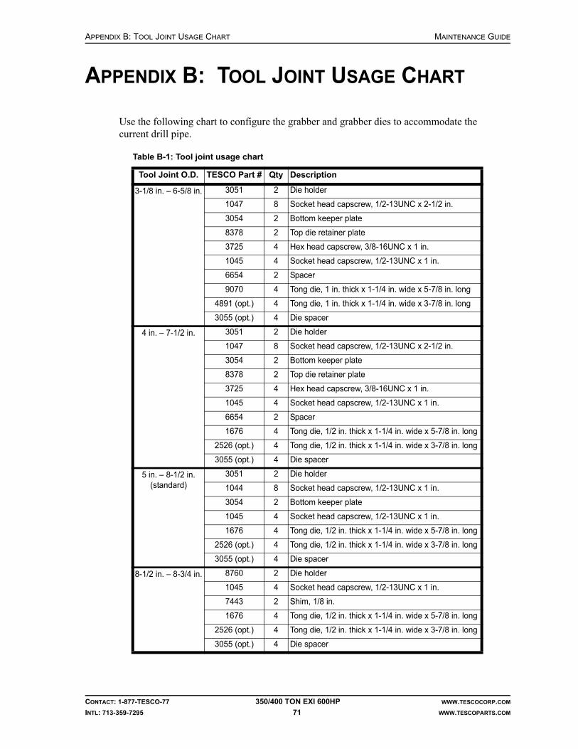
APPENDIX B: TOOL JOINT USAGE CHART MAINTENANCE GUIDE
CONTACT: 1-877-TESCO-77 350/400 TON EXI 600HP WWW.TESCOCORP.COM
INTL: 713-359-7295 71 WWW.TESCOPARTS.COM
APPENDIX B: TOOL JOINT USAGE CHART
Use the following chart to configure the grabber and grabber dies to accommodate the current drill pipe.
Table B-1: Tool joint usage chart
Tool Joint O.D. TESCO Part # Qty Description
3-1/8 in. – 6-5/8 in. 3051 2 Die holder
1047 8 Socket head capscrew, 1/2-13UNC x 2-1/2 in.
3054 2 Bottom keeper plate
8378 2 Top die retainer plate
3725 4 Hex head capscrew, 3/8-16UNC x 1 in.
1045 4 Socket head capscrew, 1/2-13UNC x 1 in.
6654 2 Spacer
9070 4 Tong die, 1 in. thick x 1-1/4 in. wide x 5-7/8 in. long
4891 (opt.) 4 Tong die, 1 in. thick x 1-1/4 in. wide x 3-7/8 in. long
3055 (opt.) 4 Die spacer
4 in. – 7-1/2 in. 3051 2 Die holder
1047 8 Socket head capscrew, 1/2-13UNC x 2-1/2 in.
3054 2 Bottom keeper plate
8378 2 Top die retainer plate
3725 4 Hex head capscrew, 3/8-16UNC x 1 in.
1045 4 Socket head capscrew, 1/2-13UNC x 1 in.
6654 2 Spacer
1676 4 Tong die, 1/2 in. thick x 1-1/4 in. wide x 5-7/8 in. long
2526 (opt.) 4 Tong die, 1/2 in. thick x 1-1/4 in. wide x 3-7/8 in. long
3055 (opt.) 4 Die spacer
5 in. – 8-1/2 in. (standard)
3051 2 Die holder
1044 8 Socket head capscrew, 1/2-13UNC x 1 in.
3054 2 Bottom keeper plate
1045 4 Socket head capscrew, 1/2-13UNC x 1 in.
1676 4 Tong die, 1/2 in. thick x 1-1/4 in. wide x 5-7/8 in. long
2526 (opt.) 4 Tong die, 1/2 in. thick x 1-1/4 in. wide x 3-7/8 in. long
3055 (opt.) 4 Die spacer
8-1/2 in. – 8-3/4 in. 8760 2 Die holder
1045 4 Socket head capscrew, 1/2-13UNC x 1 in.
7443 2 Shim, 1/8 in.
1676 4 Tong die, 1/2 in. thick x 1-1/4 in. wide x 5-7/8 in. long
2526 (opt.) 4 Tong die, 1/2 in. thick x 1-1/4 in. wide x 3-7/8 in. long
3055 (opt.) 4 Die spacer

MAINTENANCE GUIDE APPENDIX B: TOOL JOINT USAGE CHART
CONTACT: 1-877-TESCO-77 350/400 TON EXI 600HP WWW.TESCOCORP.COM
INTL: 713-359-7295 72 WWW.TESCOPARTS.COM
Table B-2: Tool joint usage chart
Tool Joint O.D.TESCO Part
#Qty Description
2-7/8 in. – 4 in. 5807 4 Die holder retainer, for 1/2 in. shims
5808 2 Shim, 1/2 in.
7588 4 Tong die, 1 in. thick x 1-1/4 in. wide x 5 in. long
3852 2 Break-away tab
6244 2 Die retainer
8626 8 Cap screw, hex head, 3/8 in. x 1-1/2 in.
3-1/4 in. – 4-1/2 in. 5807 4 Die holder retainer, for 1/2 in. shims
5808 2 Shim, 1/2 in.
1677 4 Tong die, 1 in. thick x 1-1/4 in. wide x 5 in. long
3852 2 Break-away tab
6244 2 Die retainer
8626 8 Cap screw, hex head, 3/8 in. x 1-1/2 in.
3-1/2 in.– 6-5/8 in. 3845 4 Die holder retainer
1677 4 Tong die, 1 in. thick x 1-1/4 in. wide x 5 in. long
3852 2 Break-away tab
6244 2 Die retainer
3725 8 Cap screw, hex head, 3/8 in. x 1 in.

APPENDIX C: MUD LOGGER OUTPUTS MAINTENANCE GUIDE
CONTACT: 1-877-TESCO-77 350/400 TON EXI 600HP WWW.TESCOCORP.COM
INTL: 713-359-7295 73 WWW.TESCOPARTS.COM
APPENDIX C: MUD LOGGER OUTPUTS
TESCO provides a single output for logging services. The mud logger output from the TESCO Power Module Building ‘G’ cord provides a signal for quill rpm and quill torque. The mud logger signals can be assessed for quill speed and torque via a receptacle provided for that purpose in the “Load Supply” waterfall in the Power Module Building.
Both signals are a 4 - 20mA analog signal. The mudlogger outputs are driven from a PLC analog output module. Refer to the electrical drawing package for the schematics of the particular top drive unit.
If specification data, or additional or alternate outputs are required, contact a qualified TESCO representative.
Figure C-1: Checking analog mud logger outputs

MAINTENANCE GUIDE APPENDIX C: MUD LOGGER OUTPUTS
CONTACT: 1-877-TESCO-77 350/400 TON EXI 600HP WWW.TESCOCORP.COM
INTL: 713-359-7295 74 WWW.TESCOPARTS.COM
This page has been left blank intentionally.
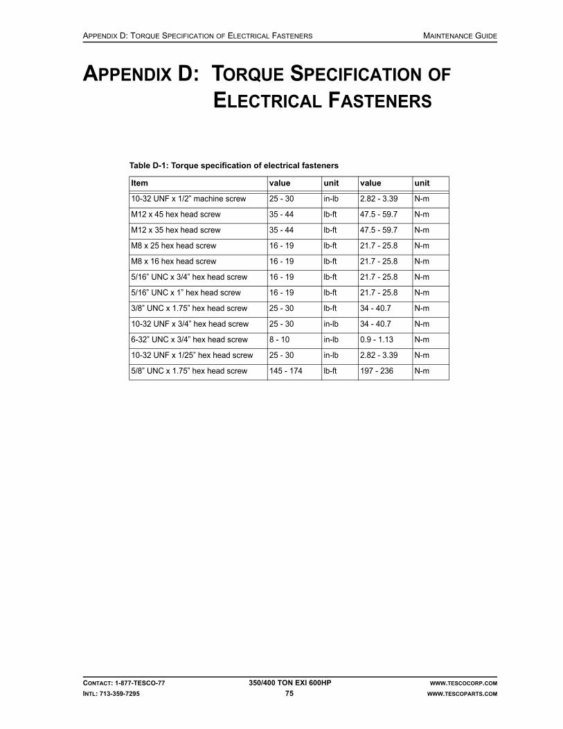
APPENDIX D: TORQUE SPECIFICATION OF ELECTRICAL FASTENERS MAINTENANCE GUIDE
CONTACT: 1-877-TESCO-77 350/400 TON EXI 600HP WWW.TESCOCORP.COM
INTL: 713-359-7295 75 WWW.TESCOPARTS.COM
APPENDIX D: TORQUE SPECIFICATION OF ELECTRICAL FASTENERS
Table D-1: Torque specification of electrical fasteners
Item value unit value unit
10-32 UNF x 1/2” machine screw 25 - 30 in-lb 2.82 - 3.39 N-m
M12 x 45 hex head screw 35 - 44 lb-ft 47.5 - 59.7 N-m
M12 x 35 hex head screw 35 - 44 lb-ft 47.5 - 59.7 N-m
M8 x 25 hex head screw 16 - 19 lb-ft 21.7 - 25.8 N-m
M8 x 16 hex head screw 16 - 19 lb-ft 21.7 - 25.8 N-m
5/16” UNC x 3/4” hex head screw 16 - 19 lb-ft 21.7 - 25.8 N-m
5/16” UNC x 1” hex head screw 16 - 19 lb-ft 21.7 - 25.8 N-m
3/8” UNC x 1.75” hex head screw 25 - 30 lb-ft 34 - 40.7 N-m
10-32 UNF x 3/4” hex head screw 25 - 30 in-lb 34 - 40.7 N-m
6-32” UNC x 3/4” hex head screw 8 - 10 in-lb 0.9 - 1.13 N-m
10-32 UNF x 1/25” hex head screw 25 - 30 in-lb 2.82 - 3.39 N-m
5/8” UNC x 1.75” hex head screw 145 - 174 lb-ft 197 - 236 N-m

MAINTENANCE GUIDE APPENDIX D: TORQUE SPECIFICATION OF ELECTRICAL FASTENERS
CONTACT: 1-877-TESCO-77 350/400 TON EXI 600HP WWW.TESCOCORP.COM
INTL: 713-359-7295 76 WWW.TESCOPARTS.COM
This page has been left blank intentionally.

APPENDIX E: SAMPLE INSPECTION LOGS MAINTENANCE GUIDE
CONTACT: 1-877-TESCO-77 350/400 TON EXI 600HP WWW.TESCOCORP.COM
INTL: 713-359-7295 77 WWW.TESCOPARTS.COM
APPENDIX E: SAMPLE INSPECTION LOGS
The following pages contain examples of inspection logs. It is important to keep detailed inspection records for all load path and torque arrest system components. Please use the following pages as a guide.
Use this log to schedule and track inspections for each load path component.
In this field Do this
Serial Number Record the component serial number.
Inspection Date Enter the date of the most recent component inspection.
Days in Service Enter the cumulative hours (or days) of service the component has been in service on the date of inspection.
Inspected By Enter the name of the company that performed the inspection.Note: Attach a copy of the inspection results to this inspection log.
Results/Comments Summarize the test results, and note any special action taken in the Additional Comments section at the bottom of the page. If a component is replaced, include the serial number for the replacement part.
Next Service Due Enter the hours (or days) of service when the component requires its next inspection.
Additional Comments Enter additional information as required.
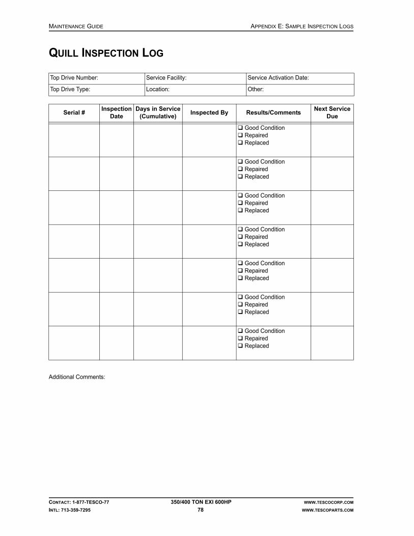
MAINTENANCE GUIDE APPENDIX E: SAMPLE INSPECTION LOGS
CONTACT: 1-877-TESCO-77 350/400 TON EXI 600HP WWW.TESCOCORP.COM
INTL: 713-359-7295 78 WWW.TESCOPARTS.COM
QUILL INSPECTION LOG
Additional Comments:
Top Drive Number: Service Facility: Service Activation Date:
Top Drive Type: Location: Other:
Serial #Inspection
DateDays in Service
(Cumulative)Inspected By Results/Comments
Next Service Due
Good Condition Repaired Replaced
Good Condition Repaired Replaced
Good Condition Repaired Replaced
Good Condition Repaired Replaced
Good Condition Repaired Replaced
Good Condition Repaired Replaced
Good Condition Repaired Replaced

APPENDIX E: SAMPLE INSPECTION LOGS MAINTENANCE GUIDE
CONTACT: 1-877-TESCO-77 350/400 TON EXI 600HP WWW.TESCOCORP.COM
INTL: 713-359-7295 79 WWW.TESCOPARTS.COM
LOAD NUT RETAINER AND SPLIT COLLAR INSPECTION LOG
Additional Comments:
Top Drive Number: Service Facility: Service Activation Date:
Top Drive Type: Location: Other:
Serial #Inspection
DateDays in Service
(Cumulative)Inspected By Results/Comments
Next Service Due
Good Condition Repaired Replaced
Good Condition Repaired Replaced
Good Condition Repaired Replaced
Good Condition Repaired Replaced
Good Condition Repaired Replaced
Good Condition Repaired Replaced
Good Condition Repaired Replaced

MAINTENANCE GUIDE APPENDIX E: SAMPLE INSPECTION LOGS
CONTACT: 1-877-TESCO-77 350/400 TON EXI 600HP WWW.TESCOCORP.COM
INTL: 713-359-7295 80 WWW.TESCOPARTS.COM
MUDSAVER VALVE INSPECTION LOG
Additional Comments:
Top Drive Number: Service Facility: Service Activation Date:
Top Drive Type: Location: Other:
Serial #Inspection
DateDays in Service
(Cumulative)Inspected By Results/Comments
Next Service Due
Good Condition Repaired Replaced
Good Condition Repaired Replaced
Good Condition Repaired Replaced
Good Condition Repaired Replaced
Good Condition Repaired Replaced
Good Condition Repaired Replaced
Good Condition Repaired Replaced

APPENDIX E: SAMPLE INSPECTION LOGS MAINTENANCE GUIDE
CONTACT: 1-877-TESCO-77 350/400 TON EXI 600HP WWW.TESCOCORP.COM
INTL: 713-359-7295 81 WWW.TESCOPARTS.COM
SAVER SUB INSPECTION LOG
Additional Comments:
Top Drive Number: Service Facility: Service Activation Date:
Top Drive Type: Location: Other:
Serial #Inspection
DateDays in Service
(Cumulative)Inspected By Results/Comments
Next Service Due
Good Condition Repaired Replaced
Good Condition Repaired Replaced
Good Condition Repaired Replaced
Good Condition Repaired Replaced
Good Condition Repaired Replaced
Good Condition Repaired Replaced
Good Condition Repaired Replaced

MAINTENANCE GUIDE APPENDIX E: SAMPLE INSPECTION LOGS
CONTACT: 1-877-TESCO-77 350/400 TON EXI 600HP WWW.TESCOCORP.COM
INTL: 713-359-7295 82 WWW.TESCOPARTS.COM
LOAD COLLAR INSPECTION LOG
Additional Comments:
Top Drive Number: Service Facility: Service Activation Date:
Top Drive Type: Location: Other:
Serial #Inspection
DateDays in Service
(Cumulative)Inspected By Results/Comments
Next Service Due
Good Condition Repaired Replaced
Good Condition Repaired Replaced
Good Condition Repaired Replaced
Good Condition Repaired Replaced
Good Condition Repaired Replaced
Good Condition Repaired Replaced
Good Condition Repaired Replaced

APPENDIX E: SAMPLE INSPECTION LOGS MAINTENANCE GUIDE
CONTACT: 1-877-TESCO-77 350/400 TON EXI 600HP WWW.TESCOCORP.COM
INTL: 713-359-7295 83 WWW.TESCOPARTS.COM
ELEVATOR LINKS INSPECTION LOG
Additional Comments:
Top Drive Number: Service Facility: Service Activation Date:
Top Drive Type: Location: Other:
Serial #Inspection
DateDays in Service
(Cumulative)Inspected By Results/Comments
Next Service Due
Good Condition Repaired Replaced
Good Condition Repaired Replaced
Good Condition Repaired Replaced
Good Condition Repaired Replaced
Good Condition Repaired Replaced
Good Condition Repaired Replaced
Good Condition Repaired Replaced
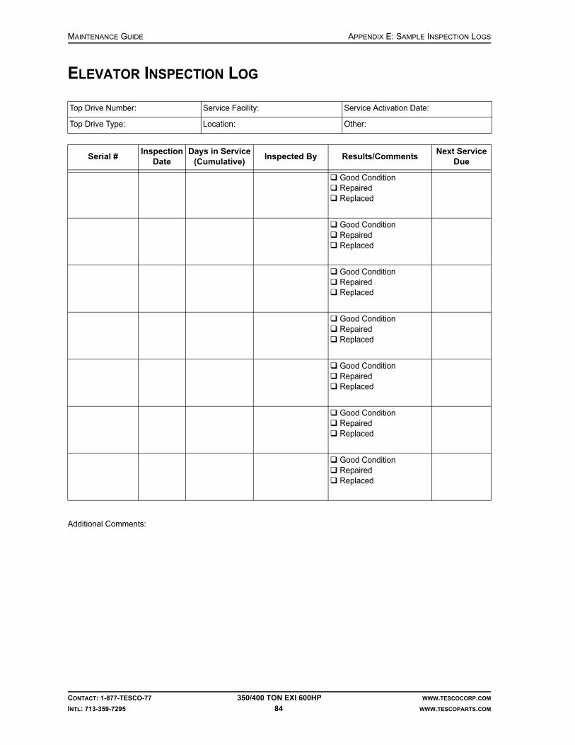
MAINTENANCE GUIDE APPENDIX E: SAMPLE INSPECTION LOGS
CONTACT: 1-877-TESCO-77 350/400 TON EXI 600HP WWW.TESCOCORP.COM
INTL: 713-359-7295 84 WWW.TESCOPARTS.COM
ELEVATOR INSPECTION LOG
Additional Comments:
Top Drive Number: Service Facility: Service Activation Date:
Top Drive Type: Location: Other:
Serial #Inspection
DateDays in Service
(Cumulative)Inspected By Results/Comments
Next Service Due
Good Condition Repaired Replaced
Good Condition Repaired Replaced
Good Condition Repaired Replaced
Good Condition Repaired Replaced
Good Condition Repaired Replaced
Good Condition Repaired Replaced
Good Condition Repaired Replaced

APPENDIX F: SERVICE CHECKLISTS MAINTENANCE GUIDE
CONTACT: 1-877-TESCO-77 350/400 TON EXI 600HP WWW.TESCOCORP.COM
INTL: 713-359-7295 85 WWW.TESCOPARTS.COM
APPENDIX F: SERVICE CHECKLISTS
This Appendix contains examples of the following checklists:
• Daily Checklist (see also Maintenance and Service Schedules)• Weekly Checklist (see also Maintenance and Service Schedules)• Monthly Checklist (see also Maintenance and Service Schedules)• Megger Test Chart
DAILY CHECKLISTS
Daily: Top Drive
IMPORTANT: This equipment was filled at the factory with TESCO ULTREX brand fluids and greases. To ensure maximum performance and to avoid cross-contamination, we strongly recommend the continued usage of TESCO ULTREX lubricants, unless otherwise specified.
Date: Supervisor:
Rig: Time:
Inspect For Inspector
Gearbox oil level correct gearbox oil level (halfway up sight glass)
Hydraulic hoses and connections at the top drive
leaks
Blower motor abnormal noise; correct operation
Lubricate With Inspector
Upper quill bearing retainer (1) TESCO ULTREX, NLGI #1 or 2
Lower quill bearing retainer (1) TESCO ULTREX, NLGI #1 or 2
Upper input shaft retainer (1) TESCO ULTREX, NLGI #1 or 2
Lower input shaft retainer (1) TESCO ULTREX, NLGI #1 or 2
Load collar grease port (1) TESCO ULTREX, NLGI #1 or 2
Tilt cylinders (4) TESCO ULTREX, NLGI #1 or 2
Extend cylinders (4) TESCO ULTREX, NLGI #1 or 2
Elevator handle pins (2) TESCO ULTREX, NLGI #1 or 2
Elevator hinge pin (1) TESCO ULTREX, NLGI #1 or 2
Mud valve actuator (1) TESCO ULTREX, NLGI #1 or 2
Pipe handler lock (1) TESCO ULTREX, NLGI #1 or 2
Swivel pins (6) TESCO ULTREX, NLGI #1 or 2
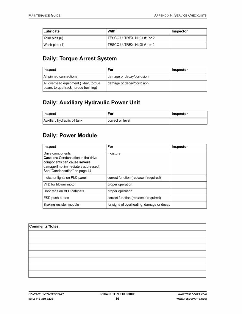
MAINTENANCE GUIDE APPENDIX F: SERVICE CHECKLISTS
CONTACT: 1-877-TESCO-77 350/400 TON EXI 600HP WWW.TESCOCORP.COM
INTL: 713-359-7295 86 WWW.TESCOPARTS.COM
Daily: Torque Arrest System
Daily: Auxiliary Hydraulic Power Unit
Daily: Power Module
Yoke pins (6) TESCO ULTREX, NLGI #1 or 2
Wash pipe (1) TESCO ULTREX, NLGI #1 or 2
Inspect For Inspector
All pinned connections damage or decay/corrosion
All overhead equipment (T-bar, torque beam, torque track, torque bushing)
damage or decay/corrosion
Inspect For Inspector
Auxiliary hydraulic oil tank correct oil level
Inspect For Inspector
Drive componentsCaution: Condensation in the drive components can cause severe damage if not immediately addressed. See “Condensation” on page 14
moisture
Indicator lights on PLC panel correct function (replace if required)
VFD for blower motor proper operation
Door fans on VFD cabinets proper operation
ESD push button correct function (replace if required)
Braking resistor module for signs of overheating, damage or decay
Comments/Notes:
Lubricate With Inspector

APPENDIX F: SERVICE CHECKLISTS MAINTENANCE GUIDE
CONTACT: 1-877-TESCO-77 350/400 TON EXI 600HP WWW.TESCOCORP.COM
INTL: 713-359-7295 87 WWW.TESCOPARTS.COM
WEEKLY CHECKLISTS
Weekly: Top Drive
Weekly: Service Loop
Date: Supervisor:
Rig: Time:
Inspect For Inspector
Hydraulic fittings tightness/leaks
Mud saver valve actuator sleeve general condition; disassemble, clean, grease, coat with corrosion inhibitor and reinstall
Counter-balance system cushion height = 2”
Motor termination boxes • moisture• tightness of all terminal block screws• tightness of all bus bar bolts• evidence of arcing
Robotics and sensor panels • moisture• tightness of wire terminations
Gearbox lubrication filter • cleanliness• check filter bypass and magnetic plug
Pipe handler rotation motors check for tightness
Load collar springs • damage• breaks
Inspect For Inspector
All service loop components damage, excessive wear
Urethane capture blocks(at top drive and roller saddle)
hose placement, tightness
Fluid quick couplers (auxiliary hydraulics)
damage or decay, tightness
All cable connections and cables(power, sensor, robotics, and ground cables)
damage, tightness, and scuffing

MAINTENANCE GUIDE APPENDIX F: SERVICE CHECKLISTS
CONTACT: 1-877-TESCO-77 350/400 TON EXI 600HP WWW.TESCOCORP.COM
INTL: 713-359-7295 88 WWW.TESCOPARTS.COM
Weekly: Torque Arrest System
Weekly: Auxiliary Hydraulic Power Unit
Weekly: Power Module
Inspect For Inspector
All bolts and threaded rods damage or decay, tightness
Torque track hanging assembly damage; close visual inspection is required
Torque bushing liner wear (the bushing liner must be replaced before the liner mounting bolts come in contact with the torque tube)
Torque bushing clearance amount of clearance (between 1/16” to 1/4”) Adjust side plates to obtain clearance as specified
Torque track stabilization components cracks or loose fasteners; close visual inspection is required
Inspect For Inspector
Electric motor and hydraulic pump unnatural noise; pump discoloration
Inspect For Inspector
Door fans cleanliness, obstructions, restrictions
Ventilation louvers cleanliness, obstructions, restrictions
Comments/Notes:

APPENDIX F: SERVICE CHECKLISTS MAINTENANCE GUIDE
CONTACT: 1-877-TESCO-77 350/400 TON EXI 600HP WWW.TESCOCORP.COM
INTL: 713-359-7295 89 WWW.TESCOPARTS.COM
MONTHLY CHECKLISTS
Monthly: Top Drive
Date: Supervisor:
Rig: Time:
Inspect For Inspector
Grabber dies excessive wear
11-station manifold general condition/leaks
Load collar correct spacing between load collar and load nut must be 0.25”
Quill end play no end play (see “How to Check for Quill End Play” on page 47)
Main auxiliary hydraulics relief valve correct setting (see “How to Set the Main Pressure Relief Valve for the Auxiliary System” on page 45)
Mud valve (lower ball) manually operate to ensure correct function
All fasteners (nuts, bolts, and lock wires)
correct location, tightness
Top drive hydraulic connections and hoses
oil leaks/deformation
Saver sub threads excessive thread wear, seal face condition
Connection locking clamps correct location, tightness
Grabber leg safety chain/shackles broken components/lock wires
Pipe bumper/motor guard dents or bends that may indicate bolt damage
Hammer union on Kelly hose integrity and tightness
Grabber/drawworks and mud valve/mud pump interlocks
function test
Gearbox lubrication system hoses • oil leaks• adequate circulation (press 60 to 120 psi when warm)
Gearbox oil analysis abnormalities (take samples to test for water, metal particles, etc.; every 900 operating hours)
Torque bushing wear liners wear and damage
Wash pipe leakage
Top drive electric connectors damage, tightness

MAINTENANCE GUIDE APPENDIX F: SERVICE CHECKLISTS
CONTACT: 1-877-TESCO-77 350/400 TON EXI 600HP WWW.TESCOCORP.COM
INTL: 713-359-7295 90 WWW.TESCOPARTS.COM
Monthly Driller’s Panel
Monthly: Service Loop
Monthly: Auxiliary Hydraulic Power Unit
Lubricate With Inspector
Hinge pins and extend frame spray with penetrating oil (WD 40, or spray lithium)
Main Motor/ Input shaft splines TESCO Ultrex, NLGI #1 or 2
Inspect For
Wire terminals in the driller’s panel tightness
Versa Max modules locked in place
Indication lights working
Switch contact blocks tightness
Inspect For
All multi-conductor connections moisture, dirt; open and check, then spray with electrical cleaner/moisture dispersant
Main service cable connectors (power, sensor, robotics, ground cables)
cleanliness; open, clean, reinstall
Inspect For Inspector
Hydraulic system pressure relief valve correct setting as per hydraulic schematic
Auxiliary system function light pressure switch
correct setting
Auxiliary hydraulic filter cleanliness; inspect and change if required
Auxiliary hydraulic fluid complete fluid analysis

APPENDIX F: SERVICE CHECKLISTS MAINTENANCE GUIDE
CONTACT: 1-877-TESCO-77 350/400 TON EXI 600HP WWW.TESCOCORP.COM
INTL: 713-359-7295 91 WWW.TESCOPARTS.COM
Monthly: Power Module
Warning! Do not perform he following checks unless the main breaker panel is disconnected and locked out.
Warning! Only qualified personnel should perform the following maintenance activities.
Inspect For Inspector
All wire terminal screws tightness
All bolted connections on both the incoming and outgoing waterfall
tightness
All bolted connections inside 600V panel tightness
VFD input and output power connections correct position and tightness
Electrical connections for the main drive components
correct torqueCritical: These connections must be torqued to specification. Severe component damage can result if they are over-tightened.
Comments/Notes:
!
!
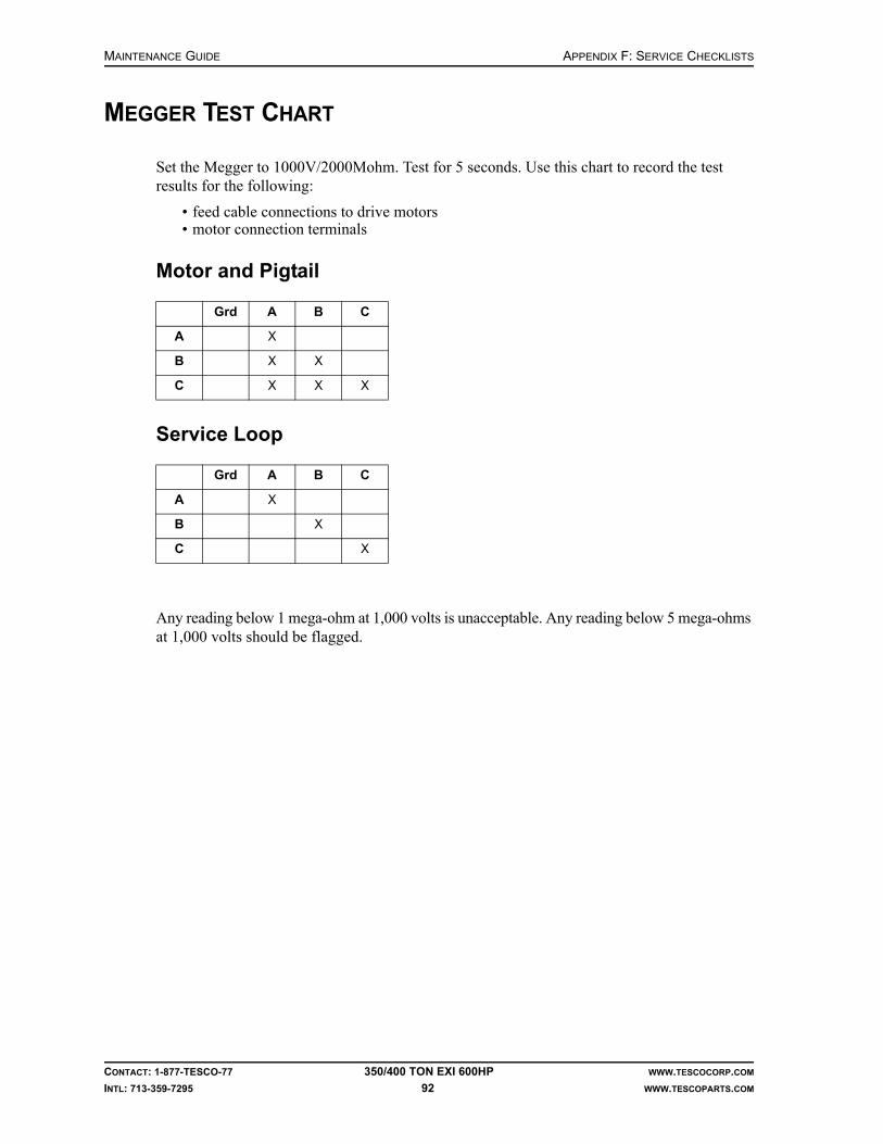
MAINTENANCE GUIDE APPENDIX F: SERVICE CHECKLISTS
CONTACT: 1-877-TESCO-77 350/400 TON EXI 600HP WWW.TESCOCORP.COM
INTL: 713-359-7295 92 WWW.TESCOPARTS.COM
MEGGER TEST CHART
Set the Megger to 1000V/2000Mohm. Test for 5 seconds. Use this chart to record the test results for the following:
• feed cable connections to drive motors• motor connection terminals
Motor and Pigtail
Service Loop
Any reading below 1 mega-ohm at 1,000 volts is unacceptable. Any reading below 5 mega-ohms at 1,000 volts should be flagged.
Grd A B C
A X
B X X
C X X X
Grd A B C
A X
B X
C X

APPENDIX F: SERVICE CHECKLISTS MAINTENANCE GUIDE
CONTACT: 1-877-TESCO-77 350/400 TON EXI 600HP WWW.TESCOCORP.COM
INTL: 713-359-7295 93 WWW.TESCOPARTS.COM
TESCO ULTREX™ LUBRICANTS
Quick Reference Guide
Engine’s Component Description
Fluid Description TESCO Part #
60 Series Detroit Advanced Formula Synthetic Blend Motor Oil SAE 15W-40 731134
12 V 2000 Series Detroit Advanced Formula Synthetic Blend Motor Oil SAE 15W-40 731134
16 V 2000 Series Detroit Advanced Formula Synthetic Blend Motor Oil SAE 15W-40 731134
All CAT Engines Advanced Formula Synthetic Blend Motor Oil SAE 15W-40 731134
12 V 92 Detroit Advanced Formula Single Weight Motor Oil SAE 40 731135
16 V 92 Detroit Advanced Formula Single Weight Motor Oil SAE 40 731135
Gear Boxes Hydraulic Top Drive’s Component Description
Fluid Description TESCO Part #
HMI(S) Advanced Performance Multi Grade Gear Oil 80W-90 731140
HS Advanced Performance Multi Grade Gear Oil 80W-90 731140
HC Advanced Performance Multi Grade Gear Oil 80W-90 731140
HCI Advanced Performance Multi Grade Gear Oil 80W-90 731140
HXI Advanced Performance Multi Grade Gear Oil 80W-90 731140
Gear Boxes Electric Top Drive’s Component Description
Fluid Description TESCO Part #
ECI 900/1350 Synthetic Multi Grade Gear Oil 75W-90 731136
EMI 450 Synthetic Multi Grade Gear Oil 75W-90 731136
EMI 400 Synthetic Multi Grade Gear Oil 75W-90 731136
EXI Synthetic Multi Grade Gear Oil 75W-90 731136
EMI 400 (H&P) Advanced Performance Gear and Bearing Oil ISO 220 731133
All TESCO Manufactured Pump Drives
Fluid Description TESCO Part #
Advanced Formula Single Weight Motor Oil SAE 40 731135
All Swivels Fluid Description TESCO Part #
Advanced Performance Gear and Bearing Oil ISO 220 731133
Advanced Performance Multi Grade Gear Oil 80W-90 731140
All TESCO Hydraulic Systems Fluid Description (either can be used) TESCO Part #
Advanced Performance Hydraulic Oil ISO 68 731143
Biodegradeable Hydraulic Oil ISO 68 731138
Grease for All TESCO Top Drives
Fluid Description (either can be used) TESCO Part #
NLGI #1 (cold weather) 48 tubes 731142-48T
NLGI #2 (hot weather) 48 tubes 731141-48T

MAINTENANCE GUIDE APPENDIX F: SERVICE CHECKLISTS
CONTACT: 1-877-TESCO-77 350/400 TON EXI 600HP WWW.TESCOCORP.COM
INTL: 713-359-7295 94 WWW.TESCOPARTS.COM
Oil Lubricants

APPENDIX F: SERVICE CHECKLISTS MAINTENANCE GUIDE
CONTACT: 1-877-TESCO-77 350/400 TON EXI 600HP WWW.TESCOCORP.COM
INTL: 713-359-7295 95 WWW.TESCOPARTS.COM

MAINTENANCE GUIDE APPENDIX F: SERVICE CHECKLISTS
CONTACT: 1-877-TESCO-77 350/400 TON EXI 600HP WWW.TESCOCORP.COM
INTL: 713-359-7295 96 WWW.TESCOPARTS.COM

APPENDIX F: SERVICE CHECKLISTS MAINTENANCE GUIDE
CONTACT: 1-877-TESCO-77 350/400 TON EXI 600HP WWW.TESCOCORP.COM
INTL: 713-359-7295 97 WWW.TESCOPARTS.COM
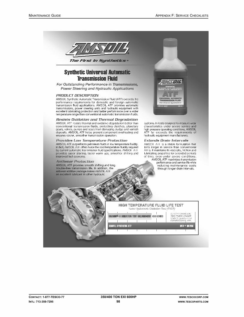
MAINTENANCE GUIDE APPENDIX F: SERVICE CHECKLISTS
CONTACT: 1-877-TESCO-77 350/400 TON EXI 600HP WWW.TESCOCORP.COM
INTL: 713-359-7295 98 WWW.TESCOPARTS.COM

APPENDIX F: SERVICE CHECKLISTS MAINTENANCE GUIDE
CONTACT: 1-877-TESCO-77 350/400 TON EXI 600HP WWW.TESCOCORP.COM
INTL: 713-359-7295 99 WWW.TESCOPARTS.COM

MAINTENANCE GUIDE APPENDIX F: SERVICE CHECKLISTS
CONTACT: 1-877-TESCO-77 350/400 TON EXI 600HP WWW.TESCOCORP.COM
INTL: 713-359-7295 100 WWW.TESCOPARTS.COM
Grease Lubricants

APPENDIX F: SERVICE CHECKLISTS MAINTENANCE GUIDE
CONTACT: 1-877-TESCO-77 350/400 TON EXI 600HP WWW.TESCOCORP.COM
INTL: 713-359-7295 101 WWW.TESCOPARTS.COM

MAINTENANCE GUIDE APPENDIX F: SERVICE CHECKLISTS
CONTACT: 1-877-TESCO-77 350/400 TON EXI 600HP WWW.TESCOCORP.COM
INTL: 713-359-7295 102 WWW.TESCOPARTS.COM
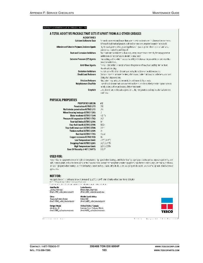
APPENDIX F: SERVICE CHECKLISTS MAINTENANCE GUIDE
CONTACT: 1-877-TESCO-77 350/400 TON EXI 600HP WWW.TESCOCORP.COM
INTL: 713-359-7295 103 WWW.TESCOPARTS.COM

MAINTENANCE GUIDE APPENDIX F: SERVICE CHECKLISTS
CONTACT: 1-877-TESCO-77 350/400 TON EXI 600HP WWW.TESCOCORP.COM
INTL: 713-359-7295 104 WWW.TESCOPARTS.COM
This page has been left blank intentionally.
INDEX MAINTENANCE GUIDE
CONTACT: 1-877-TESCO-77 350/400 TON EXI 600HP WWW.TESCOCORP.COM
INTL: 713-359-7295 105 WWW.TESCOPARTS.COM
INDEX
Numerics1,000 operating day service
auxiliary hydraulic power unit, 14service loop, 12top drive, 8
120/208 VAC panel storage, 66600 VAC panel storage, 66
Aactuating piston, grabber, 54actuator/valve orientation, 41assembly and disassembly instructions, 51auxiliary hydraulic power unit
1,000 operating day service, 14daily service, 13monthly service, 13storage, 65weekly service, 13
auxiliary systemfunctional light pressure switch, 46main pressure relief valve, 45secondary pressure relief valve, 44
Ccables and hoses storage, 63commissioning, 1component inspection guidelines, 18condensation, 14counter-balance height, 42
Ddaily inspection
top drive gearbox oil, 5torque arrest system, 12
daily serviceauxiliary hydraulic power unit, 13power module, 14top drive, 5
disassembly/assembly instructions, 51drill ahead, 1driller’s panel
functions, 1monthly service, 11storage, 63
drive system storage, 66
Eelectrical schematics, 1elevator storage, 62extend frame
monthly lubrication, 8, 13storage, 64
Ffluid specification and capacity summary, 5
Ggearbox inspection, 34gearbox lubrication schematics, 1general maintenance areas, 38grabber
change grabber dies, 53service actuating piston, 54
grabber actuating pistonreinstallation, 56removing, 54
grabber cylinder repair, 56grabber dies, changing, 53grabber disassembly and assembly, 53grabber leg
reinstallation, 58removing, 58
grabber storage, 61guidelines for component inspectors, 18
Hhanging assembly storage, 65high strength fasteners, torque standards, 67hinge pins monthly lubrication, 8, 13hose saddle storage, 65hydraulic schematics, 1
Iinformation
where to find more, 1inspection of load path components
elevator links (bails), 27elevators, 28load collar, 26load nut, 23mudsaver valve and actuator, 24quill, 22saver sub, 25

MAINTENANCE GUIDE INDEX
CONTACT: 1-877-TESCO-77 350/400 TON EXI 600HP WWW.TESCOCORP.COM
INTL: 713-359-7295 106 WWW.TESCOPARTS.COM
swivel gearbox housing, 21yoke and link assembly, 19
inspection types, 19install the top drive, 1interlocks storage, 64
Jjunction boxes storage, 60
Lload nut
components inspection, 23storage, 60
lock-out methods, 3long term storage
120/208 VAC panel, 66600 VAC panel, 66auxiliary hydraulic power unit, 65before shut down, 59cables and hoses, 63driller’s panel, 63drive output waterfall, 66drive system, 66elevators, 62extend frame, 64grabber leg, 61hanging assembly, 65hose saddle, 65incoming waterfall, 66interlocks, 64junction boxes, 60load nut, 60mudsaver valve, 62pipe handler, 61power module, 66quill, 60saver subs, 63T-bar, 65top drive, 60torque arrest system, 64torque beam, 65torque bushing, 64torque tracks, 64
Mmake connections, 1megger test chart, 92monthly service
auxiliary hydraulic power unit, 13driller’s panel, 11main service cable connectors, 11power module, 15service loop, 11
top drive, 7MPI testing
pipe handler rotation system, 32torque arrest system, 29
mud logger outputs, 73mudsaver valve
installation, 51storage, 62
multi-conductor connections, monthly service, 11
Nnon-destructive testing
pipe handler rotation system components, 32schedules, 17torque arrest system, 29
Ooptions and spares, 1
Pparts lists, 1periodic magnetic particle inspection, 29pipe handler storage, 61power module
condensation, 14daily service, 14monthly service, 15service requirements, 14storage, 66thermostat settings, 15weekly service, 15
pre-operational checklists, 1
Qquick couplers, service loop, 11quill
end play, 47inspection, 22preload, 47preload calculation and adjustment, 48storage, 60
Rrig out, 1rig up, 1roto-actuator
disassemble, 40reassemble, 41service, 40
Ssample inspection logs, 77
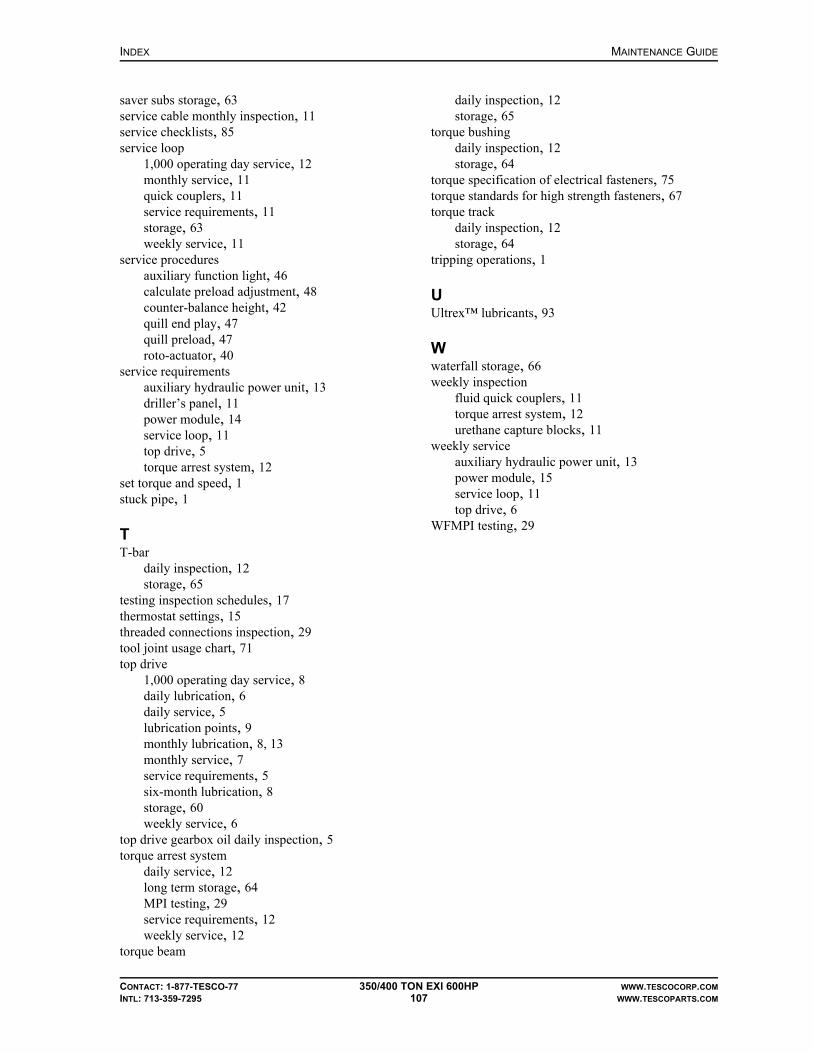
INDEX MAINTENANCE GUIDE
CONTACT: 1-877-TESCO-77 350/400 TON EXI 600HP WWW.TESCOCORP.COM
INTL: 713-359-7295 107 WWW.TESCOPARTS.COM
saver subs storage, 63service cable monthly inspection, 11service checklists, 85service loop
1,000 operating day service, 12monthly service, 11quick couplers, 11service requirements, 11storage, 63weekly service, 11
service proceduresauxiliary function light, 46calculate preload adjustment, 48counter-balance height, 42quill end play, 47quill preload, 47roto-actuator, 40
service requirementsauxiliary hydraulic power unit, 13driller’s panel, 11power module, 14service loop, 11top drive, 5torque arrest system, 12
set torque and speed, 1stuck pipe, 1
TT-bar
daily inspection, 12storage, 65
testing inspection schedules, 17thermostat settings, 15threaded connections inspection, 29tool joint usage chart, 71top drive
1,000 operating day service, 8daily lubrication, 6daily service, 5lubrication points, 9monthly lubrication, 8, 13monthly service, 7service requirements, 5six-month lubrication, 8storage, 60weekly service, 6
top drive gearbox oil daily inspection, 5torque arrest system
daily service, 12long term storage, 64MPI testing, 29service requirements, 12weekly service, 12
torque beam
daily inspection, 12storage, 65
torque bushingdaily inspection, 12storage, 64
torque specification of electrical fasteners, 75torque standards for high strength fasteners, 67torque track
daily inspection, 12storage, 64
tripping operations, 1
UUltrex™ lubricants, 93
Wwaterfall storage, 66weekly inspection
fluid quick couplers, 11torque arrest system, 12urethane capture blocks, 11
weekly serviceauxiliary hydraulic power unit, 13power module, 15service loop, 11top drive, 6
WFMPI testing, 29

MAINTENANCE GUIDE INDEX
CONTACT: 1-877-TESCO-77 350/400 TON EXI 600HP WWW.TESCOCORP.COM
INTL: 713-359-7295 108 WWW.TESCOPARTS.COM
This page has been left blank intentionally.

MAINTENANCE GUIDE
CONTACT: 1-877-TESCO-77 350/400 TON EXI 600HP WWW.TESCOCORP.COM
INTL: 713-359-7295 109 WWW.TESCOPARTS.COM
ENGINEERING SIGN-OFF
This sign-off sheet indicates that this document has been approved for release by the Engineering Department at TESCO.
Document Complete By Signature Date Signed
Document Reviewed/Approved Date Signed
chane
Typewritten Text
Edward ChanSept. 28, 2009
madejskm
Typewritten Text
Oct 22, 2009

MAINTENANCE GUIDE
CONTACT: 1-877-TESCO-77 350/400 TON EXI 600HP WWW.TESCOCORP.COM
INTL: 713-359-7295 110 WWW.TESCOPARTS.COM
This page has been left blank intentionally.

DOCUMENT NAME: 1590030 REV 0
Electrical Troubleshooting Guide
EXI600 Top Drive System
600VAC 60Hz / 50Hz Spec
Guide for End Users
Danger! Only qualified personnel should inspect electrical systems.
!


ELECTRICAL TROUBLESHOOTING GUIDE COPYRIGHT AND DISCLAIMER
CONTACT: 1-877-TESCO-77 EXI 600 HP WWW.TESCOCORP.COM
INTL: 713-359-7295 I WWW.TESCOPARTS.COM
Tesco Corporation (“TESCO”) has made every effort to ensure that this document contains accurate and current information for the TESCO top drive, however, the document is intended to be used in conjunction with a complete training program and on-site supervision and TESCO does not warrant or guarantee that the information contained herein is either complete or accurate in every respect, and the reader hereby protects, indemnifies and holds harmless Tesco Corporation together with its directors, officers, employees and agents from and against all liability for personal injury, death or property damage to any person arising directly or indirectly from the use by the reader of the information contained in the document.
This equipment was filled at the factory with TESCO ULTREX™ brand fluids and greases. To ensure maximum performance and to avoid cross-contamination, we strongly recommend the continued usage of TESCO ULTREX™ lubricants, unless otherwise specified.
TESCO ULTREX™ is a trademark and TESCO® is a registered trademark of Tesco Corporation.
Tesco Corporation © 2009
Contact Information
Corporate Head Office3993 W. Sam Houston Parkway No., Suite 100
Houston, Texas, 77043USA
www.tescocorp.comwww.tescoparts.com
Telephone: (713) 359-7000Fax: (713) 359-7001
After Market Sales and Service ContactToll Free North America: 1-877-TESCO-77
International: 713-359-7295

REVISION INFORMATION ELECTRICAL TROUBLESHOOTING GUIDE
CONTACT: 1-877-TESCO-77 EXI 600 HP WWW.TESCOCORP.COM
INTL: 713-359-7295 II WWW.TESCOPARTS.COM
Revision Information
Version Date Description of Changes
Rev 0 Jan 2009 First release

ELECTRICAL TROUBLESHOOTING GUIDE TABLE OF CONTENTS
CONTACT: 1-877-TESCO-77 EXI 600 HP WWW.TESCOCORP.COM
INTL: 713-359-7295 III WWW.TESCOPARTS.COM
TABLE OF CONTENTS
Chapter 1: About This Document . . . . . . . . . . . . . . . . . . . . . . . . . . . . . . . . . . . . . . . . . . . . . 1
Chapter 2: Main Power. . . . . . . . . . . . . . . . . . . . . . . . . . . . . . . . . . . . . . . . . . . . . . . . . . . . . . 3
Main Distribution Power . . . . . . . . . . . . . . . . . . . . . . . . . . . . . . . . . . . . . . . . . . . . . . . . . . . . . . . . . . . . 3
No Power to Power Module Building (Main Interface Breaker Will Not Close). . . . . . . . . . . . . . . . . 3
Units Equipped with a Customer-provided Main Service ESD Interface Package . . . . . . . . . . . . . . . . . . . . . . . . . . . . . . . 3
Units Equipped with a TESCO Main Service ESD Interface Package. . . . . . . . . . . . . . . . . . . . . . . . . . . . . . . . . . . . . . . . . 4
Main Interface Breaker Over-current Tripping . . . . . . . . . . . . . . . . . . . . . . . . . . . . . . . . . . . . . . . . . 5
Main Interface Breaker Trips Persistently. . . . . . . . . . . . . . . . . . . . . . . . . . . . . . . . . . . . . . . . . . . . . 5
Bard HVAC Unit . . . . . . . . . . . . . . . . . . . . . . . . . . . . . . . . . . . . . . . . . . . . . . . . . . . . . . . . . . . . . . . . 6
Features: . . . . . . . . . . . . . . . . . . . . . . . . . . . . . . . . . . . . . . . . . . . . . . . . . . . . . . . . . . . . . . . . . . . . . . . . . . . . . . . . . . . . . . . 6
Chapter 3: Power Module . . . . . . . . . . . . . . . . . . . . . . . . . . . . . . . . . . . . . . . . . . . . . . . . . . . 7
Introduction: . . . . . . . . . . . . . . . . . . . . . . . . . . . . . . . . . . . . . . . . . . . . . . . . . . . . . . . . . . . . . . . . . . . . . 7
Major Components:. . . . . . . . . . . . . . . . . . . . . . . . . . . . . . . . . . . . . . . . . . . . . . . . . . . . . . . . . . . . . . . . 7
Drive System . . . . . . . . . . . . . . . . . . . . . . . . . . . . . . . . . . . . . . . . . . . . . . . . . . . . . . . . . . . . . . . . . . 7
Option 1: OEM3000 Drive . . . . . . . . . . . . . . . . . . . . . . . . . . . . . . . . . . . . . . . . . . . . . . . . . . . . . . . . . . . . . . . . . . . . . . . . . . 7
Option 2: ABB Drive. . . . . . . . . . . . . . . . . . . . . . . . . . . . . . . . . . . . . . . . . . . . . . . . . . . . . . . . . . . . . . . . . . . . . . . . . . . . . . . 7
Main Panel . . . . . . . . . . . . . . . . . . . . . . . . . . . . . . . . . . . . . . . . . . . . . . . . . . . . . . . . . . . . . . . . . . . . 7
600V Distribution Panel . . . . . . . . . . . . . . . . . . . . . . . . . . . . . . . . . . . . . . . . . . . . . . . . . . . . . . . . . . 8
Standard 60Hz Spec . . . . . . . . . . . . . . . . . . . . . . . . . . . . . . . . . . . . . . . . . . . . . . . . . . . . . . . . . . . . . . . . . . . . . . . . . . . . . . 8
Aux VFD 50Hz Spec . . . . . . . . . . . . . . . . . . . . . . . . . . . . . . . . . . . . . . . . . . . . . . . . . . . . . . . . . . . . . . . . . . . . . . . . . . . . . . 8
15KVA Transformer . . . . . . . . . . . . . . . . . . . . . . . . . . . . . . . . . . . . . . . . . . . . . . . . . . . . . . . . . . . . . 8
120/208VAC Distribution Panel . . . . . . . . . . . . . . . . . . . . . . . . . . . . . . . . . . . . . . . . . . . . . . . . . . . . 8
Drive and Building Cooling . . . . . . . . . . . . . . . . . . . . . . . . . . . . . . . . . . . . . . . . . . . . . . . . . . . . . . . . 8
HVAC unit. . . . . . . . . . . . . . . . . . . . . . . . . . . . . . . . . . . . . . . . . . . . . . . . . . . . . . . . . . . . . . . . . . . . . 8
Addressing General Issues . . . . . . . . . . . . . . . . . . . . . . . . . . . . . . . . . . . . . . . . . . . . . . . . . . . . . . . . . 9
Chopper Module . . . . . . . . . . . . . . . . . . . . . . . . . . . . . . . . . . . . . . . . . . . . . . . . . . . . . . . . . . . . . . . . 9
Resetting from Keypad . . . . . . . . . . . . . . . . . . . . . . . . . . . . . . . . . . . . . . . . . . . . . . . . . . . . . . . . . . . 9
Measuring mA for RPM and Torque from Power Module. . . . . . . . . . . . . . . . . . . . . . . . . . . . . . . . . 9
Motor Starters Issues . . . . . . . . . . . . . . . . . . . . . . . . . . . . . . . . . . . . . . . . . . . . . . . . . . . . . . . . . . . . . 10
Motor Keeps Quitting . . . . . . . . . . . . . . . . . . . . . . . . . . . . . . . . . . . . . . . . . . . . . . . . . . . . . . . . . . . 10
Motor Quits and Will Not Start . . . . . . . . . . . . . . . . . . . . . . . . . . . . . . . . . . . . . . . . . . . . . . . . . . . . 10
Motor is Not Receiving Power . . . . . . . . . . . . . . . . . . . . . . . . . . . . . . . . . . . . . . . . . . . . . . . . . . . . 11
Auxiliary hydraulic motor/pump issues . . . . . . . . . . . . . . . . . . . . . . . . . . . . . . . . . . . . . . . . . . . . . . 11
Auxiliary Pump Motor Will Not Start . . . . . . . . . . . . . . . . . . . . . . . . . . . . . . . . . . . . . . . . . . . . . . . . 11
Chapter 4: Top Drive Power / Control . . . . . . . . . . . . . . . . . . . . . . . . . . . . . . . . . . . . . . . . 13
To Power Up EXI 600 Top Drive . . . . . . . . . . . . . . . . . . . . . . . . . . . . . . . . . . . . . . . . . . . . . . . . . . . . . 13

TABLE OF CONTENTS ELECTRICAL TROUBLESHOOTING GUIDE
CONTACT: 1-877-TESCO-77 EXI 600 HP WWW.TESCOCORP.COM
INTL: 713-359-7295 IV WWW.TESCOPARTS.COM
In 600V Distribution Panel. . . . . . . . . . . . . . . . . . . . . . . . . . . . . . . . . . . . . . . . . . . . . . . . . . . . . . . .13
Standard 60Hz Spec. . . . . . . . . . . . . . . . . . . . . . . . . . . . . . . . . . . . . . . . . . . . . . . . . . . . . . . . . . . . . . . . . . . . . . . . . . . . . . 13
Aux VFD 50Hz Spec. . . . . . . . . . . . . . . . . . . . . . . . . . . . . . . . . . . . . . . . . . . . . . . . . . . . . . . . . . . . . . . . . . . . . . . . . . . . . . 13
In 208/120V Distribution Panel . . . . . . . . . . . . . . . . . . . . . . . . . . . . . . . . . . . . . . . . . . . . . . . . . . . .13
Inside the Main Panel . . . . . . . . . . . . . . . . . . . . . . . . . . . . . . . . . . . . . . . . . . . . . . . . . . . . . . . . . . .13
Start/Stop and Reset Top Drive . . . . . . . . . . . . . . . . . . . . . . . . . . . . . . . . . . . . . . . . . . . . . . . . . . . . .14
START/STOP . . . . . . . . . . . . . . . . . . . . . . . . . . . . . . . . . . . . . . . . . . . . . . . . . . . . . . . . . . . . . . . . .14
RESET . . . . . . . . . . . . . . . . . . . . . . . . . . . . . . . . . . . . . . . . . . . . . . . . . . . . . . . . . . . . . . . . . . . . . .15
Common Motor Issues . . . . . . . . . . . . . . . . . . . . . . . . . . . . . . . . . . . . . . . . . . . . . . . . . . . . . . . . . . . .15
Run with/without Encoder . . . . . . . . . . . . . . . . . . . . . . . . . . . . . . . . . . . . . . . . . . . . . . . . . . . . . . . .15
Motor Running in Reverse direction . . . . . . . . . . . . . . . . . . . . . . . . . . . . . . . . . . . . . . . . . . . . . . . .15
Blower motor is Not Running. . . . . . . . . . . . . . . . . . . . . . . . . . . . . . . . . . . . . . . . . . . . . . . . . . . . . .15
Blower Motor Starts but Quits After a Few Seconds . . . . . . . . . . . . . . . . . . . . . . . . . . . . . . . . . . . .15
Blower Motor Will Not Turn Off . . . . . . . . . . . . . . . . . . . . . . . . . . . . . . . . . . . . . . . . . . . . . . . . . . . .16
Motor Heater Function. . . . . . . . . . . . . . . . . . . . . . . . . . . . . . . . . . . . . . . . . . . . . . . . . . . . . . . . . . .16
Setting Gearbox Temperature Switch . . . . . . . . . . . . . . . . . . . . . . . . . . . . . . . . . . . . . . . . . . . . . . .16
Chapter 5: Hydraulic Functions . . . . . . . . . . . . . . . . . . . . . . . . . . . . . . . . . . . . . . . . . . . . . 17
DC Power Related Issues . . . . . . . . . . . . . . . . . . . . . . . . . . . . . . . . . . . . . . . . . . . . . . . . . . . . . . . . . .17
Hydraulic pump not running . . . . . . . . . . . . . . . . . . . . . . . . . . . . . . . . . . . . . . . . . . . . . . . . . . . . . . . .17
Chapter 6: Viewing Drive Parameters - ABB Drive . . . . . . . . . . . . . . . . . . . . . . . . . . . . . . 19
Drive System Description . . . . . . . . . . . . . . . . . . . . . . . . . . . . . . . . . . . . . . . . . . . . . . . . . . . . . . . . . .19
Overview . . . . . . . . . . . . . . . . . . . . . . . . . . . . . . . . . . . . . . . . . . . . . . . . . . . . . . . . . . . . . . . . . . . . .19
Drive Data Manager . . . . . . . . . . . . . . . . . . . . . . . . . . . . . . . . . . . . . . . . . . . . . . . . . . . . . . . . . . . .19
Drive Control with the Panel . . . . . . . . . . . . . . . . . . . . . . . . . . . . . . . . . . . . . . . . . . . . . . . . . . . . . . . . . . . . . . . . . . . . . . . . 19
Displaying Signals . . . . . . . . . . . . . . . . . . . . . . . . . . . . . . . . . . . . . . . . . . . . . . . . . . . . . . . . . . . . . .23
Selecting Actual Signals to Display . . . . . . . . . . . . . . . . . . . . . . . . . . . . . . . . . . . . . . . . . . . . . . . . . . . . . . . . . . . . . . . . . . 23
Displaying the Full Name of the Actual Signals . . . . . . . . . . . . . . . . . . . . . . . . . . . . . . . . . . . . . . . . . . . . . . . . . . . . . . . . . 24
Viewing and Resetting Fault History. . . . . . . . . . . . . . . . . . . . . . . . . . . . . . . . . . . . . . . . . . . . . . . . . . . . . . . . . . . . . . . . . . 24
Displaying and Resetting Active Faults . . . . . . . . . . . . . . . . . . . . . . . . . . . . . . . . . . . . . . . . . . . . . . . . . . . . . . . . . . . . . . . 25
Fault History . . . . . . . . . . . . . . . . . . . . . . . . . . . . . . . . . . . . . . . . . . . . . . . . . . . . . . . . . . . . . . . . . . . . . . . . . . . . . . . . . . . . 25
List of Tasks and Relevant ABB Drive Parameters. . . . . . . . . . . . . . . . . . . . . . . . . . . . . . . . . . . . .26
Chapter 7: Viewing Drive Parameters - OEM Drive . . . . . . . . . . . . . . . . . . . . . . . . . . . . . . 27
Drive System Description . . . . . . . . . . . . . . . . . . . . . . . . . . . . . . . . . . . . . . . . . . . . . . . . . . . . . . . . . .27
Overview . . . . . . . . . . . . . . . . . . . . . . . . . . . . . . . . . . . . . . . . . . . . . . . . . . . . . . . . . . . . . . . . . . . . .27
Drive Data Manager . . . . . . . . . . . . . . . . . . . . . . . . . . . . . . . . . . . . . . . . . . . . . . . . . . . . . . . . . . . .27
Navigating Menus and Parameters . . . . . . . . . . . . . . . . . . . . . . . . . . . . . . . . . . . . . . . . . . . . . . . . . . . . . . . . . . . . . . . . . . 29
Editing Parameters . . . . . . . . . . . . . . . . . . . . . . . . . . . . . . . . . . . . . . . . . . . . . . . . . . . . . . . . . . . . . . . . . . . . . . . . . . . . . . . 30
Monitoring the Drive . . . . . . . . . . . . . . . . . . . . . . . . . . . . . . . . . . . . . . . . . . . . . . . . . . . . . . . . . . . . . . . . . . . . . . . . . . . . . . 31
History Log . . . . . . . . . . . . . . . . . . . . . . . . . . . . . . . . . . . . . . . . . . . . . . . . . . . . . . . . . . . . . . . . . . . . . . . . . . . . . . . . . . . . . 32
Chapter 8: DRIVE SPECIFIC ISSUES . . . . . . . . . . . . . . . . . . . . . . . . . . . . . . . . . . . . . . . . . 33

ELECTRICAL TROUBLESHOOTING GUIDE TABLE OF CONTENTS
CONTACT: 1-877-TESCO-77 EXI 600 HP WWW.TESCOCORP.COM
INTL: 713-359-7295 V WWW.TESCOPARTS.COM
Starting the Drive: . . . . . . . . . . . . . . . . . . . . . . . . . . . . . . . . . . . . . . . . . . . . . . . . . . . . . . . . . . . . . . . . 33
Tracing Faults . . . . . . . . . . . . . . . . . . . . . . . . . . . . . . . . . . . . . . . . . . . . . . . . . . . . . . . . . . . . . . . . . . . 34
ABB Drive . . . . . . . . . . . . . . . . . . . . . . . . . . . . . . . . . . . . . . . . . . . . . . . . . . . . . . . . . . . . . . . . . . . . 34
OEM Drive . . . . . . . . . . . . . . . . . . . . . . . . . . . . . . . . . . . . . . . . . . . . . . . . . . . . . . . . . . . . . . . . . . . 36
Drive Stops After a Few Seconds Run . . . . . . . . . . . . . . . . . . . . . . . . . . . . . . . . . . . . . . . . . . . . . . 38
Drive Main Breaker Not Energizing . . . . . . . . . . . . . . . . . . . . . . . . . . . . . . . . . . . . . . . . . . . . . . . . 38
Chapter 9: PLC/Drive Communication . . . . . . . . . . . . . . . . . . . . . . . . . . . . . . . . . . . . . . . . 39
RTU Master Communication Module. . . . . . . . . . . . . . . . . . . . . . . . . . . . . . . . . . . . . . . . . . . . . . . . . 39
Physical Layout . . . . . . . . . . . . . . . . . . . . . . . . . . . . . . . . . . . . . . . . . . . . . . . . . . . . . . . . . . . . . . . . . . 40
RTU/Modbus Protocol. . . . . . . . . . . . . . . . . . . . . . . . . . . . . . . . . . . . . . . . . . . . . . . . . . . . . . . . . . . . . 40
Initialization. . . . . . . . . . . . . . . . . . . . . . . . . . . . . . . . . . . . . . . . . . . . . . . . . . . . . . . . . . . . . . . . . . . 40
Communication. . . . . . . . . . . . . . . . . . . . . . . . . . . . . . . . . . . . . . . . . . . . . . . . . . . . . . . . . . . . . . . . 41
Common Faults . . . . . . . . . . . . . . . . . . . . . . . . . . . . . . . . . . . . . . . . . . . . . . . . . . . . . . . . . . . . . . . 42
RTU Card Not Communicating. . . . . . . . . . . . . . . . . . . . . . . . . . . . . . . . . . . . . . . . . . . . . . . . . . . . . . . . . . . . . . . . . . . . . . 42
Top Drive Not Turning After Selecting Direction, Torque, Speed . . . . . . . . . . . . . . . . . . . . . . . . . . . . . . . . . . . . . . . . . . . 42
Cimplicity Fault During Programming . . . . . . . . . . . . . . . . . . . . . . . . . . . . . . . . . . . . . . . . . . . . . . . . . . . . . . . . . . . . . . . . 42
Slow Response to Commands. . . . . . . . . . . . . . . . . . . . . . . . . . . . . . . . . . . . . . . . . . . . . . . . . . . . . . . . . . . . . . . . . . . . . . 42
Chapter 10: Driller’s Panel. . . . . . . . . . . . . . . . . . . . . . . . . . . . . . . . . . . . . . . . . . . . . . . . . . 43
Common Problems . . . . . . . . . . . . . . . . . . . . . . . . . . . . . . . . . . . . . . . . . . . . . . . . . . . . . . . . . . . . . . . 43
RTD Temperature. . . . . . . . . . . . . . . . . . . . . . . . . . . . . . . . . . . . . . . . . . . . . . . . . . . . . . . . . . . . . . 43
Drive Enable . . . . . . . . . . . . . . . . . . . . . . . . . . . . . . . . . . . . . . . . . . . . . . . . . . . . . . . . . . . . . . . . . . 43
Drive Set. . . . . . . . . . . . . . . . . . . . . . . . . . . . . . . . . . . . . . . . . . . . . . . . . . . . . . . . . . . . . . . . . . . . . 43
Drive Ready Light . . . . . . . . . . . . . . . . . . . . . . . . . . . . . . . . . . . . . . . . . . . . . . . . . . . . . . . . . . . . . . 43
Emergency Shut Down (E.S.D.) . . . . . . . . . . . . . . . . . . . . . . . . . . . . . . . . . . . . . . . . . . . . . . . . . . . 44
Speed and Torque Limits . . . . . . . . . . . . . . . . . . . . . . . . . . . . . . . . . . . . . . . . . . . . . . . . . . . . . . . . 44
How to Calibrate the Meters on the Driller’s Panel . . . . . . . . . . . . . . . . . . . . . . . . . . . . . . . . . . . . . 44
Setting LMD-120A meters . . . . . . . . . . . . . . . . . . . . . . . . . . . . . . . . . . . . . . . . . . . . . . . . . . . . . . . 45
Calibration . . . . . . . . . . . . . . . . . . . . . . . . . . . . . . . . . . . . . . . . . . . . . . . . . . . . . . . . . . . . . . . . . . . . . . . . . . . . . . . . . . . . . 45
Switch 4 adds dummy zero (5th digit, fixed zero) to extend range beyond +1999 to +19990. . . . . . . . . . . . . . . . . . . . . . 45
Setting Decimal Point of the Meter . . . . . . . . . . . . . . . . . . . . . . . . . . . . . . . . . . . . . . . . . . . . . . . . . . . . . . . . . . . . . . . . . . 45
Meter Settings . . . . . . . . . . . . . . . . . . . . . . . . . . . . . . . . . . . . . . . . . . . . . . . . . . . . . . . . . . . . . . . . . . . . . . . . . . . . . . . . . . 46
SET SPEED (rpm) . . . . . . . . . . . . . . . . . . . . . . . . . . . . . . . . . . . . . . . . . . . . . . . . . . . . . . . . . . . . . . . . . . . . . . . . . . . . . . . 46
DELIVERED SPEED (rpm) . . . . . . . . . . . . . . . . . . . . . . . . . . . . . . . . . . . . . . . . . . . . . . . . . . . . . . . . . . . . . . . . . . . . . . . . 46
SET TORQUE . . . . . . . . . . . . . . . . . . . . . . . . . . . . . . . . . . . . . . . . . . . . . . . . . . . . . . . . . . . . . . . . . . . . . . . . . . . . . . . . . . 46
DELIVERED TORQUE . . . . . . . . . . . . . . . . . . . . . . . . . . . . . . . . . . . . . . . . . . . . . . . . . . . . . . . . . . . . . . . . . . . . . . . . . . . 46
Appendix A: Speed and Torque Limits . . . . . . . . . . . . . . . . . . . . . . . . . . . . . . . . . . . . . . . 49
Appendix B: Main differences overview, 50 Hz vs 60 Hz spec . . . . . . . . . . . . . . . . . . . . 51
600VAC 50 Hz MCC Panel . . . . . . . . . . . . . . . . . . . . . . . . . . . . . . . . . . . . . . . . . . . . . . . . . . . . . . 51
Transformer . . . . . . . . . . . . . . . . . . . . . . . . . . . . . . . . . . . . . . . . . . . . . . . . . . . . . . . . . . . . . . . . . . 51
HVAC System. . . . . . . . . . . . . . . . . . . . . . . . . . . . . . . . . . . . . . . . . . . . . . . . . . . . . . . . . . . . . . . . . 51

TABLE OF CONTENTS ELECTRICAL TROUBLESHOOTING GUIDE
CONTACT: 1-877-TESCO-77 EXI 600 HP WWW.TESCOCORP.COM
INTL: 713-359-7295 VI WWW.TESCOPARTS.COM
Appendix C: Schematics: BARD Chiller. . . . . . . . . . . . . . . . . . . . . . . . . . . . . . . . . . . . . . . 53

ELECTRICAL TROUBLESHOOTING GUIDE LIST OF FIGURES
CONTACT: 1-877-TESCO-77 EXI 600 HP WWW.TESCOCORP.COM
INTL: 713-359-7295 VII WWW.TESCOPARTS.COM
LIST OF FIGURES
Figure 2-1: ESD Interface (Note: Receptacle #7 is mounted on Waterfall) . . . . . . . . . . . . . . . . . . . . . . . 5Figure 6-1: Drive Data Manager & its keys and indicators functions. . . . . . . . . . . . . . . . . . . . . . . . . . . 20Figure 7-1: Drive Data Manager & its keys and indicators functions. . . . . . . . . . . . . . . . . . . . . . . . . . . 28Figure 7-2: Navigating Menu 1 . . . . . . . . . . . . . . . . . . . . . . . . . . . . . . . . . . . . . . . . . . . . . . . . . . . . . . . 29Figure 7-3: Editing a Parameter . . . . . . . . . . . . . . . . . . . . . . . . . . . . . . . . . . . . . . . . . . . . . . . . . . . . . . 30Figure 9-1: RTM705 Layout . . . . . . . . . . . . . . . . . . . . . . . . . . . . . . . . . . . . . . . . . . . . . . . . . . . . . . . . . 40Figure 10-1: Example of the driller’s panel meter . . . . . . . . . . . . . . . . . . . . . . . . . . . . . . . . . . . . . . . . . 44Figure 10-2: LMD-120A gauge rear view . . . . . . . . . . . . . . . . . . . . . . . . . . . . . . . . . . . . . . . . . . . . . . . 45Figure A-1: Torque vs. Speed curve . . . . . . . . . . . . . . . . . . . . . . . . . . . . . . . . . . . . . . . . . . . . . . . . . . . 49

LIST OF FIGURES ELECTRICAL TROUBLESHOOTING GUIDE
CONTACT: 1-877-TESCO-77 EXI 600 HP WWW.TESCOCORP.COM
INTL: 713-359-7295 VIII WWW.TESCOPARTS.COM
sabok
Intentionally Left Blank

ELECTRICAL TROUBLESHOOTING GUIDE LIST OF TABLES
CONTACT: 1-877-TESCO-77 EXI 600 HP WWW.TESCOCORP.COM
INTL: 713-359-7295 IX WWW.TESCOPARTS.COM
LIST OF TABLES
Table 1-1: Where to Find More Information . . . . . . . . . . . . . . . . . . . . . . . . . . . . . . . . . . . . . . . . . . .1
Table 2-1: HVAC Unit specifications . . . . . . . . . . . . . . . . . . . . . . . . . . . . . . . . . . . . . . . . . . . . . . . . .6
Table 7-1: Menu 1 Parameters . . . . . . . . . . . . . . . . . . . . . . . . . . . . . . . . . . . . . . . . . . . . . . . . . . . .31
Table 7-2: History Logs Channels . . . . . . . . . . . . . . . . . . . . . . . . . . . . . . . . . . . . . . . . . . . . . . . . . .32
Table 8-1: Main faults and their remedies . . . . . . . . . . . . . . . . . . . . . . . . . . . . . . . . . . . . . . . . . . . .34
Table 8-2: Drive Parameters Readouts - Menu 1 . . . . . . . . . . . . . . . . . . . . . . . . . . . . . . . . . . . . . .36
Table 8-3: Drive Parameters Readouts - cont. . . . . . . . . . . . . . . . . . . . . . . . . . . . . . . . . . . . . . . . .36
Table 8-4: Drive Parameters Readouts - Menu 10 . . . . . . . . . . . . . . . . . . . . . . . . . . . . . . . . . . . . .37
Table 8-5: Drive Parameters Readouts - Menu 11 . . . . . . . . . . . . . . . . . . . . . . . . . . . . . . . . . . . . .38
Table 9-1: BIT LAYOUT OF THE PROGRAMMABLE STATUS WORD 0 . . . . . . . . . . . . . . . . . . .41
Table 9-2: BIT LAYOUT OF RS485 CONTROL WORD 0 . . . . . . . . . . . . . . . . . . . . . . . . . . . . . . .41

LIST OF TABLES ELECTRICAL TROUBLESHOOTING GUIDE
CONTACT: 1-877-TESCO-77 EXI 600 HP WWW.TESCOCORP.COM
INTL: 713-359-7295 X WWW.TESCOPARTS.COM
sabok
Intentionally Left Blank
ELECTRICAL TROUBLESHOOTING GUIDE
CONTACT: 1-877-TESCO-77 EXI 600 HP WWW.TESCOCORP.COM
INTL: 713-359-7295 1 WWW.TESCOPARTS.COM
CHAPTER 1: ABOUT THIS DOCUMENT
This document contains information to help you troubleshoot electrical and hydraulic compo-nents in the EMI400 Top Drive System.
A complete EMI400 Top Drive System comprises the following:• Top Drive• Power Module• Mechanical Module (Auxiliary Hydraulic Power Unit)• Interconnecting Service Loop• Torque Arrest System• Associated buildings, containers and equipment
Note: If the information in this document does not help you resolve your problem, contact a qualified TESCO representative.
Table 1-1: Where to Find More Information
For information on Refer to
System components System Description
• Top drive Installation• Rig-up procedure• Commissioning• Pre-operational checklists• Rig-out procedure
Installation Guide
• Setting torque and speed• Driller’s panel function and operating descriptions• Making connections• Drilling ahead• Tripping• Stuck pipe and free point
Operations Guide
• Load path inspections• Maintenance/service schedules• Component disassembly and reassembly
Maintenance Guide
TESCO manufactured parts and part numbers Parts List
• Electrical schematics• Hydraulic schematics• Gearbox lubrication schematics
System schematics
Available options and spares TESCO Representative

ABOUT THIS DOCUMENT ELECTRICAL TROUBLESHOOTING GUIDE
CONTACT: 1-877-TESCO-77 EXI 600 HP WWW.TESCOCORP.COM
INTL: 713-359-7295 2 WWW.TESCOPARTS.COM
sabok
Intentionally Left Blank

ELECTRICAL TROUBLESHOOTING GUIDE
CONTACT: 1-877-TESCO-77 EXI 600 HP WWW.TESCOCORP.COM
INTL: 713-359-7295 3 WWW.TESCOPARTS.COM
CHAPTER 2: MAIN POWER
Danger! Only qualified personnel should inspect electrical systems.
MAIN DISTRIBUTION POWER
The power module is fed from the Rig Interface Panel via 600VAC, 3 phase breaker, rated for 1000A in both 50Hz and 60Hz Systems (Standard). The panel is supplied either by the cus-tomer or by TESCO.
The main service ESD button is installed on the power module wall and interlocks with the Interface Panel to trip the panel breaker.
The yellow main power indicator light mounted on the VFD door inside the power module indicates continuous supply of Main Service power is maintained. It goes off when the breaker is tripped. Refer to Figure 2-1 on page 5 to troubleshoot the main service breaker tripping.
Associated Drawings: 98xxx103 Main Service ESD Interface Schematic
No Power to Power Module Building (Main Interface Breaker Will Not Close)
Units Equipped with a Customer-provided Main Service ESD Interface Package
If you cannot establish power to the power module building, perform the following checks:
1. Ensure that the rig power lock-out button in the customer motor control center (MCC) building is not active (if applicable). This button locks out power to TESCO's power module.
2. Ensure that the red Emergency Shut Down (ESD) button on the TESCO power module wall is not activated. This is the red ESD button on the VFD panel door, not the one on the driller's panel.
3. Check the ESD interface cable that connects the customer's motor control center to the TESCO power module building:
• Ensure ESD cable is plugged in.• Ensure connectors are fully seated.
Caution: Always disconnect the cable at the power source before checking pin ends.
!
!

MAIN POWER ELECTRICAL TROUBLESHOOTING GUIDE
CONTACT: 1-877-TESCO-77 EXI 600 HP WWW.TESCOCORP.COM
INTL: 713-359-7295 4 WWW.TESCOPARTS.COM
4. Check the 600V and 120V control fuses (1, 2, and 3) located in the customer's motor control center (MCC):
• Check the blown fuse indicator light for each fuse holder (if equipped). If the light is illuminated, replace the fuse.
• If the fuses do not have indicator lights, consult with a qualified electrician who can test for 600V and 120V power.
5. If none of these preliminary checks reveals a problem, the problem may be a faulty ESD cable, faulty main interface breaker under-voltage trip coil or a faulty main interface breaker.
• Have a qualified electrician confirm if there is 120VAC present to the main interface breaker under-voltage trip coil.
• If 120VAC power is present, confirm that the breaker is properly wired. Ensure the breaker does not incorporate a shunt trip coil instead of an under-voltage trip coil. Replace the under-voltage trip coil or breaker if necessary.
• If 120VAC is not present, have a qualified electrician reconfirm the ESD interface cable.
Units Equipped with a TESCO Main Service ESD Interface Package
Check the diagnostic lights on the TESCO Main Service ESD Interface cabinet. TESCO's interface cabinet contains lock-out, breaker, fusing, over/under voltage and frequency protec-tion, and diagnostic lights, which indicate which device is preventing the main breaker from setting.
1. Control Power ON indicates that control power is present. If the light is off, check the 600V and 120V control fuses (1, 2 and 3).
2. Ensure that the ESD/Lockout button on the TESCO Main Service ESD Interface cabinet is not engaged. This button locks out power to the TESCO power module.
3. Ensure that the red Emergency Shut Down (ESD) button on the TESCO power module building is not engaged. This is the red ESD button on VFD panel door, not the one on the driller's panel.
4. Check the ESD interface cable that connects the TESCO Main Service ESD Inter-face package to the TESCO power module.
a. Ensure ESD cable is plugged in.
b. Ensure connectors are fully seated.
c. Have a qualified electrician check ESD interface cable.
Caution: Always disconnect the cable at the power source end before checking pin ends.
5. Check the rig generators for the correct voltage and frequency output: 600VAC, 60Hz or 600VAC, 50Hz.
6. Check the TESCO top drive power module and cables for damage. Consult TESCO before having a qualified electrician replace the fuses. The fuses are Bussman bolt-in style, so installation should be performed only by qualified per-sonnel.
7. If the main interface breaker will not close, have a qualified electrician confirm if there is 120VAC present to the main interface breaker under-voltage trip coil.
!

ELECTRICAL TROUBLESHOOTING GUIDE MAIN POWER
CONTACT: 1-877-TESCO-77 EXI 600 HP WWW.TESCOCORP.COM
INTL: 713-359-7295 5 WWW.TESCOPARTS.COM
Confirm terminations are tight; replace the under-voltage trip coil or breaker if necessary.
Main Interface Breaker Over-current Tripping
TESCO’s top drives are powered by AC motors fed from variable frequency drives. As vari-able frequency drives are current limiting, it is not likely to trip out the main interface breaker from an over-current condition unless there is dead short present in the main power cables to the power module building.
Main Interface Breaker Trips Persistently
If you cannot maintain power to the TESCO power module building because the main inter-face breaker persistently trips, perform the following checks.
Check for under-voltage, over-voltage, under-frequency and over-frequency tripping for top drives that incorporate a TESCO Main Service ESD Interface package.
Note: Confirm that the generator meters are indicating 600V (standard units 60Hz).
Note: If your system incorporates a TESCO main service ESD interface cabinet, under-voltage, over-voltage, under-frequency and over-frequency tripping will be indicated by an illuminated Protection Relay Tripped light.
• The above only applies to top drives supplied with a TESCO Main Service ESD Inter-face Package.
Have a qualified electrician confirm if a steady 120VAC control power is present to the main interface breaker under-voltage trip coil. Confirm with a digital millimeters set to record (min/max/average).
Figure 2-1: ESD Interface (Note: Receptacle #7 is mounted on Waterfall)
D B
A C

MAIN POWER ELECTRICAL TROUBLESHOOTING GUIDE
CONTACT: 1-877-TESCO-77 EXI 600 HP WWW.TESCOCORP.COM
INTL: 713-359-7295 6 WWW.TESCOPARTS.COM
Bard HVAC Unit
The power module building is equipped with an HVAC unit for the cooling of Drive and Pan-els. It is mounted outside the building and its 3-Phase, 208VAC supply is fed via 40A breaker CB-12, CB-14 & CB-16 of the Distribution Panel inside the power module building. The sec-ond breaker is mounted inside the unit.
The Bard Wall-Mounted Air Conditioner is a self-contained, energy-efficient system, which is designed to offer maximum indoor comfort without using valuable indoor floor space or out-side ground space.
Features:
Heating, cooling, and auto/manual fan modes are thermostatically controlled from a control unit mounted inside the building. During the power module commissioning tests TESCO mon-itors operation of the HVAC unit and all its components.
Note: Refer to Manufacturer user manual for further details.
Note: For Electrical Schematics refer to Appendix C.
Table 2-1: HVAC Unit specifications
1 2 3
Model WA-372 B06 WA602-W09 WA602-E09
Capacity 3 Ton 5 Ton 5 Ton
Refrigerant type R22 R22 R22
Power 208VAC, 60Hz 208VAC, 60Hz 208VAC, 50Hz

ELECTRICAL TROUBLESHOOTING GUIDE
CONTACT: 1-877-TESCO-77 EXI 600 HP WWW.TESCOCORP.COM
INTL: 713-359-7295 7 WWW.TESCOPARTS.COM
CHAPTER 3: POWER MODULE
Danger! Only qualified personnel should inspect electrical systems.
INTRODUCTION:
All drive module components are contained within a single enclosure called the power mod-ule.
MAJOR COMPONENTS:
Drive System
Option 1: OEM3000 Drive
OEM300 electric drive is of delta structure which is a modular solution with three modules (one rectifier and two inerter modules). This input side is equipped with an 1000A main breaker (MB1) with under-voltage trip circuit and two 3-phase line reactors with thermostats. On the load side, the drive has sharing reactors. The drive system also consists of a dynamic braking unit and braking resistors which are located out side the power module building.
Option 2: ABB Drive
ABB's ACS800 (04) Series electric drive is a complete single drive module. The single drive configuration contains a rectifier, DC link and an inverter inside the brake chopper. The drive system also consists of a braking resistors which are located outside the power module build-ing
Main Panel
This panel provides the interface between the Main PLC Panel, Driller’s Panel, and sensor information from the Top Drive Panel. The Main PLC also communicates with the drive via serial link RS485. Information and commands are processed and distributed to corresponding components.
!

POWER MODULE ELECTRICAL TROUBLESHOOTING GUIDE
CONTACT: 1-877-TESCO-77 EXI 600 HP WWW.TESCOCORP.COM
INTL: 713-359-7295 8 WWW.TESCOPARTS.COM
600V Distribution Panel
Standard 60Hz Spec
This panel contains main breakers for 120/208V power distribution and for hydraulic tank heater. It also houses motor starters for the motor, the drive blower and for the auxiliary hydraulic pump.
Aux VFD 50Hz Spec
This panel contains two 10hp VFDs for auxiliary motors (top drive blower motor and auxiliary hydraulic system pump drive) and main breakers for the VFDs, 15kVA transformer and hydraulic tank heater.
15KVA Transformer
The transformer steps down the voltage from 600VAC to 120/208VAC and feeds the 120/208VAC distribution panel.
120/208VAC Distribution Panel
This panel houses breakers for AC/DC control power supply, motor heater, building lighting, panel cooling fan, and air conditioning.
Drive and Building Cooling
The drive system (either OEM or ABB) is air-cooled, with an individual blower motor for each drive section. The temperature inside the building is regulated by the HVAC unit.
HVAC unit
An HVAC unit is mounted outside the building and provides cooling for the Drive and for Panels.

ELECTRICAL TROUBLESHOOTING GUIDE POWER MODULE
CONTACT: 1-877-TESCO-77 EXI 600 HP WWW.TESCOCORP.COM
INTL: 713-359-7295 9 WWW.TESCOPARTS.COM
ADDRESSING GENERAL ISSUES
If the drive does not turn “ON” check the blown fuse indicator light and relay. If good check the ESD push button and relay. If both of these are good the UV trip coil may be bad. Check whether or not the UV coil is energized if 24VDC is present at the coil.
Chopper Module
Open the front door to the module.
• Green LED D24 (top left corner) should always be ON.• Green LED D1 (bottom left corner) should always be ON - if it is OFF you will not be
able to drill - check the thermostat on the outside mounted dynamic brake resistor to see if moisture on it is shorting the device.
Resetting from Keypad
If a RS485 trip (Red LED) is present and the reset does not work, leave everything as is. Open the PLC cabinet and pull fuse carrier 7 for 1 minute. Push the fuse carrier close and try the reset again.
Measuring mA for RPM and Torque from Power Module
TESCO provides a single output for logging services. The mudlogger output from the TESCO Power Module Building, Receptacle # 07, provides a signal for quill RPM and quill Torque. You can access the mudlogger signals for quill speed and torque via this receptacle at the waterfall.
Both signals are a 4-20mA analog signal. The mud-logger outputs are driven from a PLC ana-log output module. Refer to the electrical schematics for more receptacle pin-out and PLC ana-log output module.
If specification data or additional or alternate outputs are required, contact a qualified TESCO representative.
For Delivered Speed: A multimeter will show 12mA for 0 RPM (+ 5%) between Pin-A & Pin-B
For Delivered Torque: A multimeter will show 4mA for 0 ft-lb (+ 5%) between Pin-C & Pin-D.

POWER MODULE ELECTRICAL TROUBLESHOOTING GUIDE
CONTACT: 1-877-TESCO-77 EXI 600 HP WWW.TESCOCORP.COM
INTL: 713-359-7295 10 WWW.TESCOPARTS.COM
MOTOR STARTERS ISSUES
Warning! All electrical troubleshooting must be conducted by a qualified TESCO representative or certified technician.
This section applies to the following:
• cooling fans• auxiliary pump
Each of the above is connected to its own circuit breaker and on/off control on the main distri-bution panel.
All starters are 120VAC, refer to electrical schematics for wiring. When a corresponding relay's NO contact is closed it energizes the starter and sends 600V power to the specified motor.
Each starter contains an overload protection circuit that has been sized for the running current draw of each motor. If a motor continuously draws more power than it is designed for, the overload protection trips the starter, and the motor stops.
Motor Keeps Quitting
The most common starter problems occur when a motor is consistently overloaded. If this occurs, the Overload will open the starter and the motor will quit. To test, do the following:
1. Restart the motor.
2. Use a current meter to measure the motor’s current draw on line 1, line 2 and line 3.
Note: The draw should be roughly equal across all three legs and no leg should exceed the full load amperage of the motor (as indicated on the name plate).
Note: Tripping coil in the O/L will weaken each time an excessive power draw occurs. As the coils weaken, they will trip at lower power draws. If the power draw from the motor is within acceptable limits, but the starter continues to open, replace the O/L.
Motor Quits and Will Not Start
Overload consists of built-in heater elements. If one of the three elements fails during opera-tion, the motor may continue running using single phase power. The additional draw on the remaining lines will eventually cause one of the remaining heater elements to open the starter. The motor will quit and, because power supply is compromised, it will not start again.
If this condition occurs, start the motor and check all three lines using a current meter as fast as possible. One of the phases will show zero current. Replace the Overload.
!

ELECTRICAL TROUBLESHOOTING GUIDE POWER MODULE
CONTACT: 1-877-TESCO-77 EXI 600 HP WWW.TESCOCORP.COM
INTL: 713-359-7295 11 WWW.TESCOPARTS.COM
Motor is Not Receiving Power
If you suspect that a motor is not receiving power, perform the following checks:
1. Energize the motor breaker.
2. Using a multi-meter, test the top side of the motor starter (the line side).Note: There should be 600V phase to phase power between line 1 and line 2, line 1 and line 3, and line 2 and line 3. Power from any line to ground should be 347V.
3. If there is power at the starter, but the motor starter will not operate, check the 120V control circuit.
AUXILIARY HYDRAULIC MOTOR/PUMP ISSUES
Power supply to the auxiliary pump motor is identical to the power supply for the motors dis-cussed in the previous section. However, the auxiliary pump motor has a unique control set-up that allows the auxiliary pump to be started from either the driller's panel or the main distribu-tion panel.
If the motor is not functioning as required, and all standard power checks have been per-formed, consult this section.
Note: If the auxiliary pump can be started from the main distribution panel, but not from the driller's panel, check the cable and Pyle connectors for damage or decay.
Auxiliary Pump Motor Will Not Start
1. Check for 600V power supply as described in the section “Motor is Not Receiving Power” on page 11.
2. If 600V power is being supplied, but the motor will not start, proceed with check-ing the 120V control circuit at the power module.Note: The power module control switch normally has one open and one closed contact.
3. Using a digital multimeter, check the normally closed switch at the back of VFD panel (in the power panel) for 24V power.
4. If there is power at the switch, select Auxiliary Pump-On and Check wire P0402.
5. If there is power on wire P0402 it means the PLC is getting a signal from the switch, now check the following:• ESD Relay• Hydraulic tank level switch
6. If there is no power on wire P0402, the switch contact is bad or the switch is defective.

POWER MODULE ELECTRICAL TROUBLESHOOTING GUIDE
CONTACT: 1-877-TESCO-77 EXI 600 HP WWW.TESCOCORP.COM
INTL: 713-359-7295 12 WWW.TESCOPARTS.COM
sabok
Intentionally Left Blank

ELECTRICAL TROUBLESHOOTING GUIDE
CONTACT: 1-877-TESCO-77 EXI 600 HP WWW.TESCOCORP.COM
INTL: 713-359-7295 13 WWW.TESCOPARTS.COM
CHAPTER 4: TOP DRIVE POWER / CONTROL
The main power supply of the EXI 600 top drive is 600VAC. The system also contains 120VAC and 24/15VDC control voltages. The power distribution system of the EXI 600 mainly consists of a 600VAC distribution panel, a 15KVA transformer (600: 208/120V), and a 208/120V distribution panel.
TO POWER UP EXI 600 TOP DRIVE
1. Connect the power supply cables, motor cables, and ground cables correctly to the plug-board (waterfall) of power module building.
In 600V Distribution Panel
Standard 60Hz Spec
1. Close main breaker MB2 for hydraulic tank heater.
2. Close main breaker MB4 for 120/208V distribution.
Aux VFD 50Hz Spec
1. Close all breakers (MB2 through MB6), that feed transformer, hydraulic tank heater and the aux VFDs.
In 208/120V Distribution Panel
1. Close breaker CB1 for building lighting.
2. Close breaker CB2 for 120V control power supply.
3. Close breaker CB3 for building receptacle.
4. Close breaker CB4 for 15/24VDC power supply.
5. Close breaker CB9 for motor heater (if the ambient temperature is below 0° C).
6. Close breaker CB12/14/16 for building HVAC.
Inside the Main Panel
1. Close breaker CB1 for 24VDC power supply.
2. Close fuse F7, F8, F9, F10 of 24VDC supply for PLC and driller's panel.

TOP DRIVE POWER / CONTROL ELECTRICAL TROUBLESHOOTING GUIDE
CONTACT: 1-877-TESCO-77 EXI 600 HP WWW.TESCOCORP.COM
INTL: 713-359-7295 14 WWW.TESCOPARTS.COM
3. On VFD panel, close the main breaker for drive system.
4. Ensure the driller’s panel cable “B” is connected and 24VDC ESD relay is ener-gized.
5. Ensure all jumpers and interlocking has been completed as per schematic (Ref. to DWG 98xxx113 Sheet 2, 98xxx115 Sheet 1, 98xxx117).
6. Close the main disconnect switch on the drive. Enable the drive using a 3-position switch. The same switch can be used to trip the drive.
Danger! After tripping the drive with this switch, as the Disconnect switch is still closed and the Drive is energized.
Caution: Disconnect the main power prior to drive service!
7. Charge the spring of the main breaker until the indicator changes its color to YEL-LOW.
8. Push the green 'PUSH ON' button to close the breaker.
START/STOP AND RESET TOP DRIVE
When the EXI 600 top drive is powered up, if there is no fault in the drive system, the top drive is in READY status. The top drive will start and rotate if the START command and a non-zero speed reference are present.
START/STOP
START/STOP commands to the drive are generated from the QUILL FWD & REV switch on driller's panel (see the Driller’s Panel Chapter of the EXI Operations Guide). When the drive is ready, turn the switch away from neutral position, either to FWD or REV, to start the drive. The drive will stop once the switch is turned back to neutral position.
If the Set Speed (seethe Driller’s Panel Chapter of the EXI Operations Guide) is not zero, depending on the load, the top drive may start rotating once it is started. Increase the Set Torque by turning the TORQUE DECR & INCR switch to INCR position if the top drive is not rotating. Use the SPEED DECR & INCR switch to increase or decrease the speed. Refer to the Driller’s Panel Chapter of the EXI Operations Guide for setting speed and torque limit
!
!

ELECTRICAL TROUBLESHOOTING GUIDE TOP DRIVE POWER / CONTROL
CONTACT: 1-877-TESCO-77 EXI 600 HP WWW.TESCOCORP.COM
INTL: 713-359-7295 15 WWW.TESCOPARTS.COM
RESET
When the drive is faulty, the TRIPPED indicator on the Drive Data Manager will flash. Press the RESET button on the left side of driller's panel to reset trips after the faulty conditions have been removed. Use this button to clear any warnings or trips that may occur after power up.
Note: If the drive will not become READY, ensure that both blow fuse and auxiliary running interlocks are completed to the Drive. (Refer to Electrical Schematic 98xxx118)
COMMON MOTOR ISSUES
Run with/without Encoder
The EXI 600 top drive is equipped and intended to operate with an encoder to achieve high dynamic performance. However, to allow continuous operation in the case of a broken encoder or loss of the encoder wire, the EXI 600 can operate encoderless.
Motor Running in Reverse direction
If any of the motor is rotating in the wrong direction. Check the phase sequence only for that motor at starter, or motor terminal. If all the motors are running in reverse direction, check the phase sequence at the either Waterfall or Main Service Interface Panel.
Blower motor is Not Running
If interlocked with the PLC program, check the On and Off temperature set points in the main routine of the PLC program and compare with the actual motor temperature from RTDs. If the contactor is energizing but the blower is not running, check whether or not the 3-phase power is available.
If interlocked with the drive, check whether or not the drive run relay is energized at the User I/O board.
• If relay is energized - check wiring.• If relay is not energized - check interlocks for this relay (refer to electrical schematics).
Blower Motor Starts but Quits After a Few Seconds
• Check the blower motor pressure switch. • Check whether or not the switch contacts are switching when blower is running. • Check pressure switch input at PLC terminal P0412. • Try adjusting pressure switch adjustment screw all the way out. • Check the tube connections with ports at pressure switch, if problem still exists, replace
pressure switch.

TOP DRIVE POWER / CONTROL ELECTRICAL TROUBLESHOOTING GUIDE
CONTACT: 1-877-TESCO-77 EXI 600 HP WWW.TESCOCORP.COM
INTL: 713-359-7295 16 WWW.TESCOPARTS.COM
Blower Motor Will Not Turn Off
Ensure there is a signal back from each of the RTDs. When RTDs fail the PLC assumes high temperature and keeps the blower running constantly. Measure ohms across each RTD, if one or more RTD shows as offline, use spare RTDs and check PLC Logic for temperature reading (Rung25).
Motor Heater Function
When the top drive main motor is not running, is the motor heater working? Check heater ampere DR relay terminal 21/22. Normally this heater draws up to 2.0 A
Setting Gearbox Temperature Switch
6900TUE temperature switch maximum set point range on increasing temperature is 250ºF. The set point temperature varies 3.5ºF (+1.5ºF) per one revolution of the internal adjustment wheel.
1. Access the internal adjustment wheel by opening the adjustment wheel access cover marked “Decreasing/Increasing” located on the front of the temperature switch.
2. With a flathead screwdriver rotate the adjustment wheel in the “Increasing” direc-tion as indicated on the adjustment wheel. This will equate to approximately 202ºF (+1.5ºF).
3. Once step two is completed, with a flathead screwdriver, rotate the adjustment wheel three full revolutions in the “Decreasing” direction as indicated on the adjustment wheel access cover. This will equate to approximately 192ºF (+1.5 ºF).
4. Close adjustment wheel access cover. This completes the field adjustment of the gearbox temperature switch.

ELECTRICAL TROUBLESHOOTING GUIDE
CONTACT: 1-877-TESCO-77 EXI 600 HP WWW.TESCOCORP.COM
INTL: 713-359-7295 17 WWW.TESCOPARTS.COM
CHAPTER 5: HYDRAULIC FUNCTIONS
Many hydraulic system problems exhibit similar symptoms. To pinpoint the exact cause of any difficulty you should follow a proper testing procedure.
DC POWER RELATED ISSUES
An example of a case where the hydraulic function is not operating properly is when the grab-ber is not opening/closing or the elevator is not working. These are the result of 24VDC direc-tional control (solenoid) valve malfunction.
First ensure that proper output signals from the output card (slot 5) are coming out when each hydraulic function is operated. Refer to electrical schematic of each solenoid valve for wiring details. If it is confirmed that the output card sends a signal to energize a solenoid valve, check if the solenoid valve is energized. If 24VDC is present on the valve terminals but the valve is not shifting, replace the solenoid valve. If 24VDC is not present at the solenoid terminals, check connection at the Pyle receptacle.
HYDRAULIC PUMP NOT RUNNING
Ensure all hoses are connected and the pump is not dead headed. This can cause the overload to trip. If all hoses are connected correctly, measure the resistance from phase to phase with a digital multimeter set to Ohms readout. Each reading should be within 5-10% between phases, otherwise you could have a faulty motor, which has to be replaced.

HYDRAULIC FUNCTIONS ELECTRICAL TROUBLESHOOTING GUIDE
CONTACT: 1-877-TESCO-77 EXI 600 HP WWW.TESCOCORP.COM
INTL: 713-359-7295 18 WWW.TESCOPARTS.COM
sabok
Intentionally Left Blank

ELECTRICAL TROUBLESHOOTING GUIDE
CONTACT: 1-877-TESCO-77 EXI 600 HP WWW.TESCOCORP.COM
INTL: 713-359-7295 19 WWW.TESCOPARTS.COM
CHAPTER 6: VIEWING DRIVE PARAMETERS - ABB DRIVE
DRIVE SYSTEM DESCRIPTION
Overview
The TESCO EXI 600 Top Drive features WL600HP AC Vector motor and ACS800 Electric Drive system. The nominal voltage for the drive system is 600VAC (60Hz) and can be sup-plied by either a self-contained generator or directly from the rig's AC bus.
The WL600HP motor is rated at 600HP (447kW) with 150% overload capability for 60 sec-onds. The maximum motor speed is 2,400 rpm. The motor produces 2,600 ft-lb of continuous torque within nominal speed range.
The stator windings have embedded RTDs to monitor motor temperature.
The ACS800 electric drive is of delta structure which is a modular solution with 2 modules (one rectifier and two inverter modules) required to run a 600HP top drive.
The EXI600 top drive system employs speed control with variable torque limits control scheme. The drive is controlled by a main PLC via RS485 serial communication. It receives START/STOP commands, speed reference, and torque limits from the PLC and at the same time sends back speed feedback, torque demand, and drive status to the PLC as well.
ACS800 is equipped with a Drive Data Manager that allows full access and monitoring of drive parameters.
Drive Data Manager
The Drive Data Manager is a multi-purpose unit which provides keypad functions and has a 4-line, 20-digit display. It also includes four Led which indicate the status of the drive. The Drive Data Manager is mounted on the main panel inside the power building.
Drive Control with the Panel
The user can control the drive with the panel as follows:
• start, stop, and change direction of the motor • give the motor speed reference or torque reference

VIEWING DRIVE PARAMETERS - ABB DRIVE ELECTRICAL TROUBLESHOOTING GUIDE
CONTACT: 1-877-TESCO-77 EXI 600 HP WWW.TESCOCORP.COM
INTL: 713-359-7295 20 WWW.TESCOPARTS.COM
• give a process reference (when the process PID control is active) • reset the fault and warning messages • change between local and external drive control.
When the drive is under local control and the status row is visible on the display the panel can be used for control of the drive.
The figure below shows the Drive Data Manager and describes the functions of the indicators and keys.
.
Figure 6-1: Drive Data Manager & its keys and indicators functions

ELECTRICAL TROUBLESHOOTING GUIDE VIEWING DRIVE PARAMETERS - ABB DRIVE
CONTACT: 1-877-TESCO-77 EXI 600 HP WWW.TESCOCORP.COM
INTL: 713-359-7295 21 WWW.TESCOPARTS.COM

VIEWING DRIVE PARAMETERS - ABB DRIVE ELECTRICAL TROUBLESHOOTING GUIDE
CONTACT: 1-877-TESCO-77 EXI 600 HP WWW.TESCOCORP.COM
INTL: 713-359-7295 22 WWW.TESCOPARTS.COM

ELECTRICAL TROUBLESHOOTING GUIDE VIEWING DRIVE PARAMETERS - ABB DRIVE
CONTACT: 1-877-TESCO-77 EXI 600 HP WWW.TESCOCORP.COM
INTL: 713-359-7295 23 WWW.TESCOPARTS.COM
Displaying Signals
Selecting Actual Signals to Display
In the Actual Signal Display Mode, the user can:
• show three actual signals on the display at a time • select the actual signals to display • view the fault history • reset the fault history.
The panel enters the Actual Signal Display Mode when the user presses the ACT key, or if he/she does not press any key within one minute.

VIEWING DRIVE PARAMETERS - ABB DRIVE ELECTRICAL TROUBLESHOOTING GUIDE
CONTACT: 1-877-TESCO-77 EXI 600 HP WWW.TESCOCORP.COM
INTL: 713-359-7295 24 WWW.TESCOPARTS.COM
Displaying the Full Name of the Actual Signals
Viewing and Resetting Fault History
Attention! The fault history cannot be reset if there are active faults or warnings.

ELECTRICAL TROUBLESHOOTING GUIDE VIEWING DRIVE PARAMETERS - ABB DRIVE
CONTACT: 1-877-TESCO-77 EXI 600 HP WWW.TESCOCORP.COM
INTL: 713-359-7295 25 WWW.TESCOPARTS.COM
Displaying and Resetting Active Faults
Warning! If an external source for start command is selected and it is ON, the drive will start immediately after fault reset. If the cause of the fault has not been removed, the drive will trip again.
Fault History
The fault history restores information on the latest events (faults, warnings, and resets) of the drive. The table below shows how the events are stored in the fault history.
!

VIEWING DRIVE PARAMETERS - ABB DRIVE ELECTRICAL TROUBLESHOOTING GUIDE
CONTACT: 1-877-TESCO-77 EXI 600 HP WWW.TESCOCORP.COM
INTL: 713-359-7295 26 WWW.TESCOPARTS.COM
List of Tasks and Relevant ABB Drive Parameters

ELECTRICAL TROUBLESHOOTING GUIDE
CONTACT: 1-877-TESCO-77 EXI 600 HP WWW.TESCOCORP.COM
INTL: 713-359-7295 27 WWW.TESCOPARTS.COM
CHAPTER 7: VIEWING DRIVE PARAMETERS - OEM DRIVE
DRIVE SYSTEM DESCRIPTION
Overview
The TESCO EXI 600 Top Drive features WL600HP AC Vector motor and OEMV3000 Elec-tric Drive system. The nominal voltage for the drive system is 600VAC (60Hz) and can be supplied by either a self-contained generator or directly from the rig's AC bus.
The WL600HP motor is rated at 600HP (447kW) with 150% overload capability for 60 sec-onds. The maximum motor speed is 2,400 rpm. The motor produces 2,600 ft-lb of continuous torque within nominal speed range.
The stator windings have embedded RTDs to monitor motor temperature.
The OEMV3000 electric drive is of delta structure which is a modular solution with 3 modules (one rectifier and two inverter modules) required to run a 600HP top drive.
The EXI600 top drive system employs speed control with variable torque limits control scheme. The drive is controlled by a main PLC via RS485 serial communication. It receives START/STOP commands, speed reference, and torque limits from the PLC and at the same time sends back speed feedback, torque demand, and drive status to the PLC as well.
OEMV3000 is equipped with Drive Data Manager that allows full access and monitoring of drive parameters.
Drive Data Manager
The Drive Data Manager is a multi-purpose unit which provides keypad functions and has a 4-line, 20-digit display. It also includes four LEDs which indicate the status of the drive. The Drive Data Manager is mounted on the main panel inside the power building.
The Drive Data Manager functions include:
• setting and displaying drive parameters• monitoring drive status• displaying warnings and trips• maintaining track history

VIEWING DRIVE PARAMETERS - OEM DRIVE ELECTRICAL TROUBLESHOOTING GUIDE
CONTACT: 1-877-TESCO-77 EXI 600 HP WWW.TESCOCORP.COM
INTL: 713-359-7295 28 WWW.TESCOPARTS.COM
Fig-7-1(Illustration 1) shows the Drive Data Manager and describes the functions of indicators and keys.
Figure 7-1: Drive Data Manager & its keys and indicators functions

ELECTRICAL TROUBLESHOOTING GUIDE VIEWING DRIVE PARAMETERS - OEM DRIVE
CONTACT: 1-877-TESCO-77 EXI 600 HP WWW.TESCOCORP.COM
INTL: 713-359-7295 29 WWW.TESCOPARTS.COM
Navigating Menus and Parameters
Use the 4-way navigation key to browse through menus and parameters.
As an example, navigating Menu 1 is shown in Figure 7-2. Other menus are treated in exactly the same way.
Figure 7-2: Navigating Menu 1

VIEWING DRIVE PARAMETERS - OEM DRIVE ELECTRICAL TROUBLESHOOTING GUIDE
CONTACT: 1-877-TESCO-77 EXI 600 HP WWW.TESCOCORP.COM
INTL: 713-359-7295 30 WWW.TESCOPARTS.COM
Editing Parameters
Fig. 6-3 shows an example of editing parameter P2.00. Follow the same procedure to edit other parameters.
EXI 600 Drive System parameters are protected by a security code that prevents accidental editing. Only parameters of Menu 1, Menu 10 and Menu 27 are accessible for monitoring and display purpose. Parameters in these three menus are read-only. Menu 1 is configured to dis-play key parameters and status of the drive, Menu 10 is for warning and trip information, and Menu 27 is for history log.
Figure 7-3: Editing a Parameter

ELECTRICAL TROUBLESHOOTING GUIDE VIEWING DRIVE PARAMETERS - OEM DRIVE
CONTACT: 1-877-TESCO-77 EXI 600 HP WWW.TESCOCORP.COM
INTL: 713-359-7295 31 WWW.TESCOPARTS.COM
Monitoring the Drive
The Drive Data Manager has the function of monitoring and displaying the operation status of the drive system and Menu 1 is configured for such purpose. The table below lists the parame-ters in Menu 1.
Table 7-1: Menu 1 Parameters
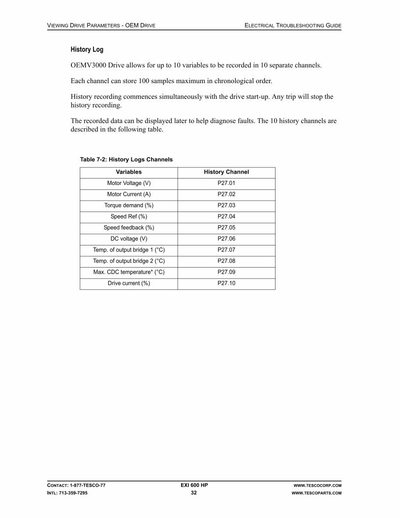
VIEWING DRIVE PARAMETERS - OEM DRIVE ELECTRICAL TROUBLESHOOTING GUIDE
CONTACT: 1-877-TESCO-77 EXI 600 HP WWW.TESCOCORP.COM
INTL: 713-359-7295 32 WWW.TESCOPARTS.COM
History Log
OEMV3000 Drive allows for up to 10 variables to be recorded in 10 separate channels.
Each channel can store 100 samples maximum in chronological order.
History recording commences simultaneously with the drive start-up. Any trip will stop the history recording.
The recorded data can be displayed later to help diagnose faults. The 10 history channels are described in the following table.
Table 7-2: History Logs Channels
Variables History Channel
Motor Voltage (V) P27.01
Motor Current (A) P27.02
Torque demand (%) P27.03
Speed Ref (%) P27.04
Speed feedback (%) P27.05
DC voltage (V) P27.06
Temp. of output bridge 1 (°C) P27.07
Temp. of output bridge 2 (°C) P27.08
Max. CDC temperature* (°C) P27.09
Drive current (%) P27.10

ELECTRICAL TROUBLESHOOTING GUIDE
CONTACT: 1-877-TESCO-77 EXI 600 HP WWW.TESCOCORP.COM
INTL: 713-359-7295 33 WWW.TESCOPARTS.COM
CHAPTER 8: DRIVE SPECIFIC ISSUES
STARTING THE DRIVE:
1. Ensure the drillers panel is disabled (switch on the side).
2. Turn on all breakers in Panel Board 208V/120V.
3. Turn on MB2 (only if hydraulic oil heater is required), MB3 and MB4 in the 600V Control panel.
4. Make sure overloads 1M, 2M, 3M are not tripped (look at rectangular hole at top left of reset switch). If one is tripped turn the switch to the left to reset.
5. Charge the main 600V breaker by pumping on the handle until the indicator says the spring is charged.
6. Press the ON button.
7. The breaker will close and the indicator will display “ON”, at the same time the indicator for the spring will show “discharged”.
8. Open the panel door with the interface controller on it.
9. Close CB 1.
10. Close Fuses 7, 8, 9, 10.
11. At the driller’s panel the Green Ready Light and the Green Temp light now should be on.
12. Press the RESET button on the side of the driller's panel for 3 seconds.
13. Set the desired torques and speed with the set key on the side of the driller's panel as per TESCO EXI600 Operations Manual.
14. Press the RESET button on the side of the driller's panel for 3 seconds.
15. ENABLE the driller's panel.
16. The “Module ON” light should turn on.
17. Start drilling.

DRIVE SPECIFIC ISSUES ELECTRICAL TROUBLESHOOTING GUIDE
CONTACT: 1-877-TESCO-77 EXI 600 HP WWW.TESCOCORP.COM
INTL: 713-359-7295 34 WWW.TESCOPARTS.COM
TRACING FAULTS
ABB Drive
1. Make sure all breakers, overloads and fuses are still set and are good.
2. Move to the electronic interface panel mounted on the drive.
3. To see the faults use the procedure “Displaying and Resetting Active Faults” on page 25.Note: When a fault is detected, it is stored in the Fault History. The latest faults and warnings are stored together with the time stamp at which the event was detected.
Note: The fault logger collects 64 of the latest faults. When the drive power is switched off, 16 of the latest faults are stored.
Note: See original manufacturer’s ACS800 Drive Programming manual for more details.
Table 8-1: Main faults and their remedies
Faults Cause Action
ACS800 TEMP (4210)
A drive IGBT temperature increase. Trip limit is 100%.
• Check motor power. • Check flow of air and fan is working. • Check the environment condition
BC overheat (7114)
Brake Chopper overloaded • Check parameter setting of Group 27• Check the allowable limit of braking
cycle.• Check the AC supply Voltage, it should
be within limit
DC BUS LIM (3211)
Motor reaches torque limit due to intermediate DC.Voltage is too high or too low.
• Check Fault Function parameters
INV Disabled (3200)
When Inverter was stopped, optional DC switch is opened
• Close the switch and check fuse switch controller unit
INV OVERTEMP Converter temperature is beyond limit
• Check if ambient temperature has not exceeded 40ºC.
• Check inlet air filter.• Check if air circulation is proper. If not,
change or clean the heat sink
Motor STALL(7121)
Motor runs in Stall range due to either insufficient power or excessive load
• Check fault function parameters.• Check drive rating and motor load
DC OVERVOLT (3210)
Excessive intermediate circuit DC voltage.The trip limit for DC overvoltage is 1.3*U1Max, where U1Max is the main voltage range max value
• Check if parameter 20.05 is ON.• Check brake resistor (if used).• Check deceleration time.• Use coast to stop function.• Retrofit frequency converter with brake
chopper and brake resistor.
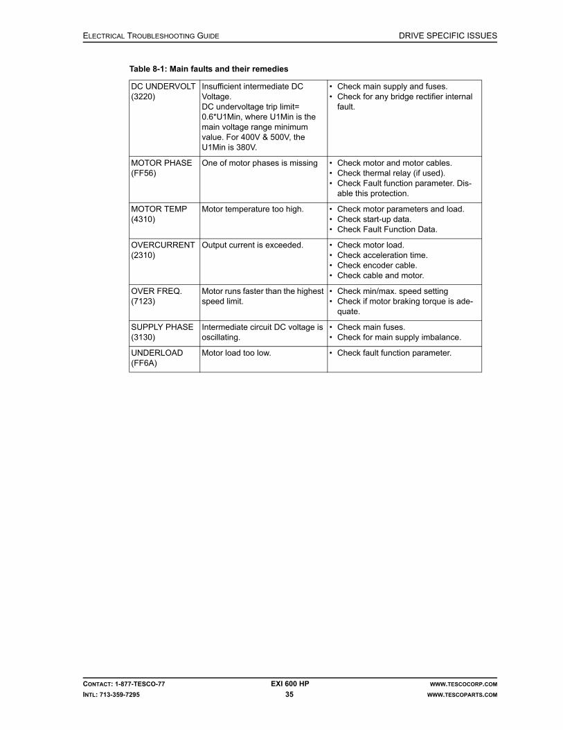
ELECTRICAL TROUBLESHOOTING GUIDE DRIVE SPECIFIC ISSUES
CONTACT: 1-877-TESCO-77 EXI 600 HP WWW.TESCOCORP.COM
INTL: 713-359-7295 35 WWW.TESCOPARTS.COM
DC UNDERVOLT (3220)
Insufficient intermediate DC Voltage.DC undervoltage trip limit= 0.6*U1Min, where U1Min is the main voltage range minimum value. For 400V & 500V, the U1Min is 380V.
• Check main supply and fuses. • Check for any bridge rectifier internal
fault.
MOTOR PHASE (FF56)
One of motor phases is missing • Check motor and motor cables.• Check thermal relay (if used).• Check Fault function parameter. Dis-
able this protection.
MOTOR TEMP (4310)
Motor temperature too high. • Check motor parameters and load.• Check start-up data.• Check Fault Function Data.
OVERCURRENT(2310)
Output current is exceeded. • Check motor load.• Check acceleration time.• Check encoder cable.• Check cable and motor.
OVER FREQ.(7123)
Motor runs faster than the highest speed limit.
• Check min/max. speed setting• Check if motor braking torque is ade-
quate.
SUPPLY PHASE(3130)
Intermediate circuit DC voltage is oscillating.
• Check main fuses.• Check for main supply imbalance.
UNDERLOAD (FF6A)
Motor load too low. • Check fault function parameter.
Table 8-1: Main faults and their remedies

DRIVE SPECIFIC ISSUES ELECTRICAL TROUBLESHOOTING GUIDE
CONTACT: 1-877-TESCO-77 EXI 600 HP WWW.TESCOCORP.COM
INTL: 713-359-7295 36 WWW.TESCOPARTS.COM
OEM Drive
1. First make sure all Breakers, Overloads, and Fuses are still set and are good. Then move to the electronic interface mounted on the drive.
2. Press the ESC button.
3. Press the arrow key until you find “MENU 1”.
4. Press ENTER. You will come to the first Parameter (referred to as P below).
5. Record all of the following values: Note: Readings with proper values for the top drive not rotating and Module ON light being on are shown in italic bold font below.
Note: To scroll to the next parameter i.e., from P01 to P02 press the arrow [ ]
6. If the unit has tripped, record the type of trip.
7. Then try to reset the trip by pressing the [?] button while looking at the live trip. This will bring up a menu with four items in it.
8. Press [#3] to attempt a reset.
9. If the reset works the trip will clear and you will be able to drill unless there are any other faults.
Table 8-2: Drive Parameters Readouts - Menu 1
Parameter # Description Value
P1 0.0 Speed Feed Back 0%
P1.01 Torque Demand 0%
P1.02 Motor Current 0 Amps
P1.03 Motor Power 0 KW
P1.04 Motor Volts 0 V
P1.05 Prog Status Word 0 04C2H
P1.06 Warning No 1 0
P1.07 Trip No 1 0
Table 8-3: Drive Parameters Readouts - cont.
Parameter # Description Value
P1.08 Trip No 2 0
P1.10 RS485 Reference 1 0%
P1.11 RS485 Ref 2 2.66%
P1.12 RS485 Control Word 0 0004H
P1.16 DC Link Voltage 825V
P1.17 Drive Current 0%
P1.18 Enc Angle 23.9º
P1.19 Motor Nom Speed 1174rpm
P1.20 Motor Power Factor .9

ELECTRICAL TROUBLESHOOTING GUIDE DRIVE SPECIFIC ISSUES
CONTACT: 1-877-TESCO-77 EXI 600 HP WWW.TESCOCORP.COM
INTL: 713-359-7295 37 WWW.TESCOPARTS.COM
10. Press the ESC button.
11. Press the arrow key until you find “MENU 10”.
12. Press ENTER which will bring you to the first Parameter (referred to as P below) of this menu.
13. Record all of the following values: Note: Readings with proper values for the Top Drive not rotating and Module ON light being on are shown in italic bold font below.
Note: To scroll to the next parameter i.e. from P10.01 to P10.02 hit the arrow [ ]
P1.21 Maximum Speed Forward 2192
P1.22 Maximum Speed Reverse 2192
P1.23 Minimum Speed Forward 0
P1.24 Minimum Speed Reverse 0
P1.25 Acceleration Rate Forward 20%/sec
P1.26 Deceleration Rate Reverse 30%/sec
P1.27 User Text Language 1
P1.28 Drive Nom Current 600A
P1.29 Overload duty 0150% O/Load
P1.30 No of Deltas 2
Table 8-4: Drive Parameters Readouts - Menu 10
Parameter # Description Value
P10.00 Warning No
P10.01 Warning No 2
P10.02 Warning No 3
P10.03 Warning No 4
P10.04 Warning No 5
P10.05 Warning No 6
P10.06 Warning No 7
P10.07 Warning No 8
P10.08 Warning No 9
P10.09 Warning No 10
P10.10 Trip No 1
P10.11 Trip No 2
P10.12 Trip No 3
P10.13 Trip No 4
P10.14 Trip No 5
Table 8-3: Drive Parameters Readouts - cont.

DRIVE SPECIFIC ISSUES ELECTRICAL TROUBLESHOOTING GUIDE
CONTACT: 1-877-TESCO-77 EXI 600 HP WWW.TESCOCORP.COM
INTL: 713-359-7295 38 WWW.TESCOPARTS.COM
14. Press the ESC button.
15. Press the arrow key until you find “MENU 11”.
16. Press ENTER which brings you to the first Parameter (referred to as P below) of this menu.
17. Record all of the following values: Note: Readings with proper values for the Top Drive not rotating and Module ON light being on are shown in italic bold font below.
Note: To scroll to the next parameter i.e. from P11.01 to P11.02 hit the arrow [ ]
Drive Stops After a Few Seconds Run
1. If the drive stops after a few seconds run and each time the delay time is different, check Drive Interlock at User I/O board terminal TB3-9 for interlocks.
2. Then see TB3-7 to find out if the robotic functions are running or not.
3. Refer to Electrical Schematics 98xxx118.
Drive Main Breaker Not Energizing
1. Check BFS and ESD relays. Both of these relays should be energized.
2. If BFS relay is not energized, check micro switches at each of the fuses inside the VFD.
3. If ESD relay is not energized, check ESD loop. Make sure E-stop PB at driller’s panel is not pushed.
4. Check Fuse F-8.
5. If everything is OK, check 24VDC across UV coil of MB1 breaker. If 24VDC is present then the UV coil is bad.
P10.15 Trip No 6
P10.16 Trip No 7
P10.17 Trip No 8
P10.18 Trip No 9
P10.19 Trip No 10
Table 8-5: Drive Parameters Readouts - Menu 11
Parameter # Description Value
P11.04 Electronic CDC Temperature
P11.05 IGBT 1 Temperature
P11.06 IGBT 2 Temperature
P11.08 Rectifier Temperature
P11.13 Max CDC Electronic Temp 47ºC
P11.14 Min CDC Electronic Temp 19ºC
Table 8-4: Drive Parameters Readouts - Menu 10

ELECTRICAL TROUBLESHOOTING GUIDE
CONTACT: 1-877-TESCO-77 EXI 600 HP WWW.TESCOCORP.COM
INTL: 713-359-7295 39 WWW.TESCOPARTS.COM
CHAPTER 9: PLC/DRIVE COMMUNICATION
RTU MASTER COMMUNICATION MODULE
HE693RTM705 Remote Terminal Unit provides the PLC (Series 90-30) with a flexible com-munication interface with RTU/Modbus network. It functions as a master that allows data to be read and/or written to one or more slave devices. It resides in a single local slot and is com-patible with the CPU331 or larger. In thios particular application it uses CPU363.
It provides two Modbus/RTU master channels which may be controlled by the 90-30 to access data from remote slave RTU's. Each channel can be individually programmed for dial in, dial out, radio modem, multi-drop (RS422/RS485), and direct connection (RS232) operation. Each channel can send or receive Analog or Discrete data using standard RTU commands (i.e. Read Coil). Multiple commands can be sent to each slave with each command requesting either a single point or multiple contiguous points of up to 250 bytes. Data to be sent or stored is placed in the 90-30 reference data tables. The tables define which RTU commands are sent to slave RTUs. Once started, the RTM705 uses these command lists to run in a semi-unsuper-vised state to transfer data between the 90-30 data tables and the slave RTUs.
The length of time between updates to each slave RTU can be individually adjusted. Each slave RTU has an individual status field, which reflects the condition of communications with that RTU. By continuously monitoring each status field, the 90-30 can detect configuration or communication problems on a slave by slave basis.

PLC/DRIVE COMMUNICATION ELECTRICAL TROUBLESHOOTING GUIDE
CONTACT: 1-877-TESCO-77 EXI 600 HP WWW.TESCOCORP.COM
INTL: 713-359-7295 40 WWW.TESCOPARTS.COM
PHYSICAL LAYOUT
The RTM705 module features three indicating LEDs: , (Port 1) and (Port 2).
At power-up, the light flashes to indicate that the module is cycling through its initial-
ization self-tests. Once the self-tests are complete, LED remains solidly lit. and
Ports lights become solidly lit after hardware initialization (refer to the figure below).
After the PLC ladder logic initializes a port with a COM_REQ, it checks for slaves. If the slave(s) is found and is working correctly, the LEDs go out, and during operation only flicker
with port activity. If a fatal error occurs, LED flashes an error code.
RTU/MODBUS PROTOCOL
The Modbus/RTU protocol uses a Master/Slave protocol that can support a common bus of one master and up to 247 Modbus Slaves. That common bus can be extended from direct wir-ing to radio and telephone modems. As an RTU master, commands are constructed and issued to an addressed slave. Only the addressed slave is expected to respond to the command. Mes-sage integrity is assured through use of checksums included in a message.
Initialization
Before the RTM can send acceptable RTU commands, it must be configured to the frame pro-tocol used by the slave RTU's. On power up, the RTM waits for an initialization through a COM_REQ before beginning to process RTU commands.
Before the COM_REQ can be issued, a pair of lists, SCB (Slave Control Block, 15 words, in this application it starts from R00701 to R00715) and MCB (Message Control Block, 6 words, in this application it starts from R00801 to R00806) must be preloaded in an appropriate PLC reference data table [%R, %AI, %AQ] with scanned information. These lists specify the Slaves, which are scanned and the RTU command(s) which are sent to the slave RTUs. Each
Figure 9-1: RTM705 Layout
OK P1 P2
OK
OK P1
P2
P1

ELECTRICAL TROUBLESHOOTING GUIDE PLC/DRIVE COMMUNICATION
CONTACT: 1-877-TESCO-77 EXI 600 HP WWW.TESCOCORP.COM
INTL: 713-359-7295 41 WWW.TESCOPARTS.COM
communication port requires its own set of lists and associated COM_REQ (17 words, in this application it starts from R00901 to R00917). A 5 seconds delay should be implemented in the ladder code before the COM_REQ is called.
There are three primary tasks to be performed by the PLC ladder logic: initialize the RTU Module, Read/write Modbus/RTU data and monitor communication status. For further details and other information refer to the User Manual.
Communication
With EXI600, the drive is controlled by PLC via RS485 serial communication. The drive com-municates with PLC using MODBUS RTU protocol. From the PLC it receives:
• RUN/STOP commands: when drive is ready, turn the switch away from neutral posi-tion, either to QUILL FWD or REV, to start the drive and the drive will stop once the switch is returned to neutral position
• Speed reference: SPEED INC(rease) & DEC(rease) switch generates speed refer-ence signal
• Torque limit: TORQUE INC(rease) & DEC(rease) Switch and at the same time sends back speed feedback, torque demand, and drive status to PLC as well.
The Drive status and communication with the PLC can be monitored via programmable status word (from drive to PLC) and control word (from PLC to drive). The following are control word & status words.
Table 9-1: BIT LAYOUT OF THE PROGRAMMABLE STATUS WORD 0
Bit 11-15
Bit 10 Bit 9 Bit 8 Bit 7 Bit 6 Bit 5 Bit 4 Bit 3 Bit 2 Bit 1 Bit 0
Spare Drive Ready
Encoder Bypass
Aux. Running
Inter-lock Zero Speed
REV Warning Drive Trip Drive Start
Drive Stop
Drive Running
Table 9-2: BIT LAYOUT OF RS485 CONTROL WORD 0
Bit 5-15 Bit 4 Bit 3 Bit 2 Bit 1 Bit 0
Spare Direction 1=REV Reset Trip ESD Stop Stop Drive Start Drive

PLC/DRIVE COMMUNICATION ELECTRICAL TROUBLESHOOTING GUIDE
CONTACT: 1-877-TESCO-77 EXI 600 HP WWW.TESCOCORP.COM
INTL: 713-359-7295 42 WWW.TESCOPARTS.COM
Common Faults
RTU Card Not Communicating.
If Green LED is not blinking it means RTU card is not communicating with the Drive. Reboot the PLC first, if it does not work then reboot both PLC and Drive.
Top Drive Not Turning After Selecting Direction, Torque, Speed
Check if there are any Trip/Warning indications at PLC Rack, SLOT 4 - You must have input A5 (ESD OK) and B4 (Chopper Module OK) illuminated to be able to drill.
If you have selected a direction, torque and speed and the top drive is not turning and you have no trips or warnings, make sure the pipe handler is “off” and check to see if the top drive blower motor and the drive blower motor are working.
If the top drive blower motor is working, check PLC SLOT 4 indicator B3. This should be illu-minated, if not check the pressure switch on the top drive.
Cimplicity Fault During Programming
If you uploaded a new program and the status bar of Cimplicity software shows a fault (a dia-mond with red F), try to Reset the fault from the table a few times, not only from I/O.
Slow Response to Commands
If commands are not reacting normally, check the resistance of the termination resistor. It should be between 100-110 Ohm. Replace the resistor if the value is not in range. A faulty resistor may also cause a loss of communication.
P2

ELECTRICAL TROUBLESHOOTING GUIDE
CONTACT: 1-877-TESCO-77 EXI 600 HP WWW.TESCOCORP.COM
INTL: 713-359-7295 43 WWW.TESCOPARTS.COM
CHAPTER 10: DRILLER’S PANEL
COMMON PROBLEMS
RTD Temperature
If the temperature of the motor windings (RTDs, one of the PLC inputs AI201, AI202 and AI203) exceeds 155°C, the “System Temperature” light on the driller's panel through output Q65 (LED A1 ON) will flash 3 times per second. If the temperature of the motor windings (RTDs, one of the PLC inputs AI201, AI202 and AI203) exceeds 175°C, the “System Temper-ature” light on the driller's panel through output Q65 (LED A1 ON) will turn off and the DRS Drive will shut down.
Drive Enable
When the ENABLE switch is in the ON position Input I89 (LED B09 ON) goes ‘HIGH’. The Drive Enable Command is sent to the Drive. When the ENABLE switch is in the OFF position input I89 (LED B09 OFF) becomes ‘LOW’. The Drive Disable Command is sent to the DRS Drive.
Drive Set
When the ENABLE switch is in the OFF position (Input I89, LED B09 OFF) and “Drive Set” key is held in the SET position (Input I91, LED B11 ON), then drive adjustment parameters can be altered.
Releasing “Drive Set” key will save the settings into PLC memory.
Note: top drive will not rotate if Drive Set parameters are not set to operating requirements or are set @ 0. Ensure you have sufficient Drive Set parameter range.
Drive Ready Light
After enabling the drive through PLC Input I89 (LED B09 ON), the drive performs its own system test. After successfully completing the test, the drive sends the signal (M00131) to PLC. After receiving that signal, PLC energizes “Ready Light” on the driller's panel through the output Q71 (LED A7 ON).
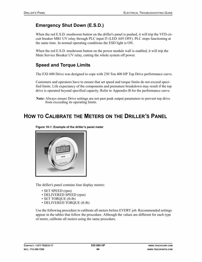
DRILLER’S PANEL ELECTRICAL TROUBLESHOOTING GUIDE
CONTACT: 1-877-TESCO-77 EXI 600 HP WWW.TESCOCORP.COM
INTL: 713-359-7295 44 WWW.TESCOPARTS.COM
Emergency Shut Down (E.S.D.)
When the red E.S.D. mushroom button on the driller's panel is pushed, it will trip the VFD cir-cuit breaker MB1 UV relay through PLC input I5 (LED A05 OFF). PLC stops functioning at the same time. In normal operating conditions the ESD light is ON.
When the red E.S.D. mushroom button on the power module wall is enabled, it will trip the Main Service Breaker UV relay, cutting the whole system off power.
Speed and Torque Limits
The EXI 600 Drive was designed to cope with 250 Ton 400 HP Top Drive performance curve.
Customers and operators have to ensure that set speed and torque limits do not exceed speci-fied limits. Life expectancy of the components and premature breakdown may result if the top drive is operated beyond specified capacity. Refer to Appendix-B for the performance curve.
Note: Always ensure Drive settings are not past peak output parameters to prevent top drive from exceeding its operating limits.
HOW TO CALIBRATE THE METERS ON THE DRILLER’S PANEL
The driller's panel contains four display meters:
• SET SPEED (rpm)• DELIVERED SPEED (rpm)• SET TORQUE (ft-lb)• DELIVERED TORQUE (ft-lb)
Use the following procedure to calibrate all meters before EVERY job. Recommended settings appear in the tables that follow the procedure. Although the values are different for each type of meter, calibrate all meters using the same procedure.
Figure 10-1: Example of the driller’s panel meter

ELECTRICAL TROUBLESHOOTING GUIDE DRILLER’S PANEL
CONTACT: 1-877-TESCO-77 EXI 600 HP WWW.TESCOCORP.COM
INTL: 713-359-7295 45 WWW.TESCOPARTS.COM
Setting LMD-120A meters
Caution: Ensure the quill is motionless whenever any meter adjust-ment work is being done.
Calibration
Although the values are different for each type of meter, you can calibrate all meters using the same procedure.
1. Meters are factory set for a 4-20mA signal.
2. Switch 1, 2, 3 control decimal points position.
Switch 4 adds dummy zero (5th digit, fixed zero) to extend range beyond +1999 to +19990.
Setting Decimal Point of the Meter
1. Stop quill rotation at the top drive.
2. Open the driller’s panel and access the meter.
3. The calibration controls are at the rear of the meter. To access them, remove the rear plug.
4. For the SET SPEED and DELIVERED SPEED meters:
This will display the rpm as a whole number without any decimal places.
Figure 10-2: LMD-120A gauge rear view
Switch Setting
1 0
2 0
3 0
4 0
!

DRILLER’S PANEL ELECTRICAL TROUBLESHOOTING GUIDE
CONTACT: 1-877-TESCO-77 EXI 600 HP WWW.TESCOCORP.COM
INTL: 713-359-7295 46 WWW.TESCOPARTS.COM
5. For the SET TORQUE and DELIVERED TORQUE meters:
This will display the torque values in thousands of foot-pounds. For example, a reading of 20.3 means 20,300 ft-lb.
6. Replace the plug.
7. Calibrate the zero and maximum values according to “Meter Calibration” on page 47.
Meter Settings
The following tables show the recommended settings for each of the meters on the driller's panel.
SET SPEED (rpm)
DELIVERED SPEED (rpm)
SET TORQUE
DELIVERED TORQUE
Switch Setting
1 0
2 0
3 1
4 0
Meter Option Settings
Signal4-12 mA12-20mA
4 mA =220 rpm; 12 mA = 0 rpm12 mA = 0 rpm; 20 mA = 220 rpm
Meter Option Settings
Signal4-12 mA12-20mA
4 mA = -220 rpm; 12 mA = 0 rpm12 mA = 0 rpm; 20 mA = 220 rpm
Meter Option Settings
Signal 4–20 mA 4 mA = 0; 20 mA = 45,000 lb ft
Meter Option Settings
Signal 4–20 mA 4 mA = 0; 20 mA = 45,000 lb ft

ELECTRICAL TROUBLESHOOTING GUIDE DRILLER’S PANEL
CONTACT: 1-877-TESCO-77 EXI 600 HP WWW.TESCOCORP.COM
INTL: 713-359-7295 47 WWW.TESCOPARTS.COM
Meter Calibration
Inspection Point Data/Notes
SET SPEED meter SET SPEED meter calibration: Set meter dip-switch setting to 0000 (verify with electrical
engineering department) Using loop calibrator, set ZERO ADJUST (zero) and SPAN
ADJUST (max) until meter displays the following values:4 mA = 0 rpm20 mA = 220 rpm Repeat ZERO ADJUST and SPAN ADJUST and adjust if
necessary Repeat ZERO ADJUST and SPAN ADJUST again and adjust if
necessary
DELIVERED SPEED meter DELIVERED SPEED meter calibration: Set meter dip-switch setting to 0000 (verify with electrical
engineering department) Using loop calibrator, adjust set ZERO ADJUST (zero) and SPAN
ADJUST (max) until meter displays the following values:4 mA = -220 rpm20 mA = 220 rpm Repeat ZERO ADJUST and SPAN ADJUST and adjust if
necessary Repeat ZERO ADJUST and SPAN ADJUST again and adjust if
necessary
SET TORQUE meter SET TORQUE meter calibration: Set meter dip-switch setting to 0010 (verify with electrical
engineering department) Using loop calibrator, set ZERO ADJUST (zero) and SPAN
ADJUST (max) until meter displays the following values:4 mA = 0 ft-lb20 mA = 45.0 (×1000) ft-lb Repeat ZERO ADJUST and SPAN ADJUST and adjust if
necessary Repeat ZERO ADJUST and SPAN ADJUST again and adjust if
necessary
DELIVERED TORQUE meter DELIVERED TORQUE meter calibration: Set meter dip-switch setting to 0010 (verify with electrical
engineering department) Using loop calibrator, set ZERO ADJUST (zero) and SPAN
ADJUST (max) until meter displays the following values:4 mA = 0 ft-lb20 mA = 45.0 (×1000) ft-lb Repeat ZERO ADJUST and SPAN ADJUST and adjust if
necessary Repeat ZERO ADJUST and SPAN ADJUST again and adjust if
necessary

DRILLER’S PANEL ELECTRICAL TROUBLESHOOTING GUIDE
CONTACT: 1-877-TESCO-77 EXI 600 HP WWW.TESCOCORP.COM
INTL: 713-359-7295 48 WWW.TESCOPARTS.COM
sabok
Intentionally Left Blank

ELECTRICAL TROUBLESHOOTING GUIDE
CONTACT: 1-877-TESCO-77 EXI 600 HP WWW.TESCOCORP.COM
INTL: 713-359-7295 49 WWW.TESCOPARTS.COM
APPENDIX A: SPEED AND TORQUE LIMITS
The EXI 600 Top Drive was designed to meet 250 Ton 400 HP Top Drive performance curve.
Customers and operators have to ensure that speed and torque limits are applied and monitored as not to exceed specified curve. Life expectancy of the components and premature breakdown may result if top drive is operated beyond specified limits.
Figure A-1: Torque vs. Speed curve

SPEED AND TORQUE LIMITS ELECTRICAL TROUBLESHOOTING GUIDE
CONTACT: 1-877-TESCO-77 EXI 600 HP WWW.TESCOCORP.COM
INTL: 713-359-7295 50 WWW.TESCOPARTS.COM
sabok
Intentionally Left Blank

ELECTRICAL TROUBLESHOOTING GUIDE
CONTACT: 1-877-TESCO-77 EXI 600 HP WWW.TESCOCORP.COM
INTL: 713-359-7295 51 WWW.TESCOPARTS.COM
APPENDIX B: MAIN DIFFERENCES OVERVIEW, 50 HZ VS 60 HZ SPEC
Subject to the Customer requirements, EXI 600 Top Drive was designed to operate with either 60 or 50Hz Drive system. The main differences between the two are as follows:
600VAC 50 Hz MCC Panel
1. Both the Auxiliary pump and the blower motor are powered by VFD1 and VFD2 units and controlled via PLC control signals.
2. 12A and 8A Line reactors are used to supply the input voltage to VFD1 and to VFD2, powering the Blower motor and auxiliary pump drive motor respectively.Note: In 60 Hz configuration both Aux pump drive and blower motors are pow-ered via and 2M and 3M contactor and thermal overload.
3. Cooling fan is powered through an F1fuse, located in 120/208 VAC Power Distri-bution panel.
4. Green indicator light for Blower - ON signal is powered from VFD2 contacts 11&12 to TB3 contacts 2 & 8, all located in 600V/ AUX VFD Panel.
5. Both VFD1 (Auxiliary Hydraulic Pump motor) and VFD2 (Blower motor) are Normally Open contacts (terminals 11 - 12 and 24 - 25 respectively) and are used to supply input signals to the PLC Panel.
6. White indicator light for Main Power - ON signal is powered from TB-MPEM contacts 2&4 located in 600V/ AUX VFD Panel, to Receptacle 07, located in the waterfall panel.
Transformer
The dual-frequency 50Hz/60Hz transformer (15kVA, 600/120-208 VAC, 3Phase CE/CSA/UL) is used in 50 Hz spec system.
HVAC System
The 50 Hz system uses a 5-Ton, 208VAC, WA602-E09 unit.

MAIN DIFFERENCES OVERVIEW, 50 HZ VS 60 HZ SPEC ELECTRICAL TROUBLESHOOTING GUIDE
CONTACT: 1-877-TESCO-77 EXI 600 HP WWW.TESCOCORP.COM
INTL: 713-359-7295 52 WWW.TESCOPARTS.COM
sabok
Intentionally Left Blank

ELECTRICAL TROUBLESHOOTING GUIDE SCHEMATICS: BARD CHILLER
CONTACT: 1-877-TESCO-77 EXI 600 HP WWW.TESCOCORP.COM
INTL: 713-359-7295 53 WWW.TESCOPARTS.COM
APPENDIX C: SCHEMATICS: BARD CHILLER

SCHEMATICS: BARD CHILLER ELECTRICAL TROUBLESHOOTING GUIDE
CONTACT: 1-877-TESCO-77 EXI 600 HP WWW.TESCOCORP.COM
INTL: 713-359-7295 54 WWW.TESCOPARTS.COM
sabok
Intentionally Left Blank

ELECTRICAL TROUBLESHOOTING GUIDE
CONTACT: 1-877-TESCO-77 EXI 600 HP WWW.TESCOCORP.COM
INTL: 713-359-7295 55 WWW.TESCOPARTS.COM
ENGINEERING SIGN-OFF
This sign-off sheet indicates that this document has been approved for release by the Engineering Department at TESCO.
Document Complete By Signature Date Signed
Document Reviewed/Approved Date Signed
madejskm
Typewritten Text
April 9, 2009

ELECTRICAL TROUBLESHOOTING GUIDE
CONTACT: 1-877-TESCO-77 EXI 600 HP WWW.TESCOCORP.COM
INTL: 713-359-7295 56 WWW.TESCOPARTS.COM

DOCUMENT NAME: 880081 REV 0
List of Parts and Assemblies
EXI 600 Top Drive System
400TON EXI 600HP/60Hz
Unit 871

LIST OF PARTS AND ASSEMBLIES EXI-600 TOP DRIVE SYSTEM
CONTACT: 1-877-TESCO-77 I WWW.TESCOCORP.COM
INTL: 713-359-7295 WWW.TESCOPARTS.COM
Tesco Corporation ("TESCO") has made every effort to ensure that this document contains accurate and current information for the TESCO top drive, however, the document is intended to be used in conjunction with a complete training program and on-site supervision and TESCO does not warrant or guarantee that the information contained herein is either complete or accurate in every respect, and the reader hereby protects, indemnifies and holds harmless Tesco Corporation together with its directors, officers, employees and agents from and against all liability for personal injury, death or property damage to any person arising directly or indirectly from the use by the reader of the information contained in the document.
This equipment was filled at the factory with TESCO ULTREX™ brand fluids and greases. To ensure maximum performance and to avoid cross-contamination, we strongly recommend the continued usage of TESCO ULTREX™ lubricants, unless otherwise specified.
TESCO ULTREX™ is a trademark and TESCO® is a registered trademark of Tesco Corporation.
Tesco Corporation © 2010
Contact Information
Corporate Head Office3993 W. Sam Houston Parkway N., Suite 100
Houston, Texas, 77043USA
www.tescocorp.comwww.tescoparts.com
Telephone: (713) 359-7000Fax: (713) 359-7001
After Market Sales and Service ContactToll Free North America: 1-877-TESCO-77
International: 713-359-7295

EXI-600 TOP DRIVE SYSTEM LIST OF PARTS AND ASSEMBLIES
CONTACT: 1-877-TESCO-77 II WWW.TESCOCORP.COM
INTL: 713-359-7295 WWW.TESCOPARTS.COM
Revision Information
Version Date Description of Changes
Rev 0 August 2010 First release of the EXI parts lists, Unit 871

LIST OF PARTS AND ASSEMBLIES EXI-600 TOP DRIVE SYSTEM
CONTACT: 1-877-TESCO-77 III WWW.TESCOCORP.COM
INTL: 713-359-7295 WWW.TESCOPARTS.COM
TABLE OF CONTENTS
About This Document . . . . . . . . . . . . . . . . . . . . . . . . . . . . . . . . . . . . . Section 1
Top Drive. . . . . . . . . . . . . . . . . . . . . . . . . . . . . . . . . . . . . . . . . . . . . . . . Section 2

EXI-600 TOP DRIVE SYSTEM LIST OF PARTS AND ASSEMBLIES
CONTACT: 1-877-TESCO-77 IV WWW.TESCOCORP.COM
INTL: 713-359-7295 WWW.TESCOPARTS.COM
This page has been left blank intentionally.

LIST OF PARTS AND ASSEMBLIES EXI-600 TOP DRIVE SYSTEM
CONTACT: 1-877-TESCO-77 WWW.TESCOCORP.COM
INTL: 713-359-7295 WWW.TESCOPARTS.COM
SECTION 1: ABOUT THIS DOCUMENT
This chapter contains all the parts lists and the accompanying illustrations for the 400TON EXI 600HP/60Hz top drive system.
The illustrations are drawn from the off driller’s side point of view.
Table 1-1: Where to Find More Information
For information on Refer to
system components overview System Description
• installation• rig up• commissioning• pre-operational checklists• rig out procedures
Installation Guide
• setting torque and speed• driller's panel functions and operating descriptions• making connections• drilling ahead• tripping• freeing stuck pipe
Operations Guide
• load path inspections• maintenance/service schedules• component disassembly and reassembly
Maintenance Guide
TESCO manufactured parts and part numbers Parts List
troubleshooting Troubleshooting Guide (where available)
• electrical schematics• hydraulic schematics• gearbox lubrication schematics
System schematics
available options and spares TESCO Representative

EXI-600 TOP DRIVE SYSTEM LIST OF PARTS AND ASSEMBLIES
CONTACT: 1-877-TESCO-77 WWW.TESCOCORP.COM
INTL: 713-359-7295 WWW.TESCOPARTS.COM
This page has been left blank intentionally.

LIST OF PARTS AND ASSEMBLIES EXI-600 TOP DRIVE SYSTEM
CONTACT: 1-877-TESCO-77 WWW.TESCOCORP.COM
INTL: 713-359-7295 WWW.TESCOPARTS.COM
SECTION 2: TOP DRIVE

EXI-600 TOP DRIVE SYSTEM LIST OF PARTS AND ASSEMBLIES
CONTACT: 1-877-TESCO-77 WWW.TESCOCORP.COM
INTL: 713-359-7295 WWW.TESCOPARTS.COM
This page has been left blank intentionally.

EXI600 TOP DRIVE, PART NUMBER 5001927 LIST OF PARTS AND ASSEMBLIES
CONTACT: 1-877-TESCO-77 2-1 WWW.TESCOCORP.COMINTL: 713-359-7295 WWW.TESCOPARTS.COM
EXI600 TOP DRIVE, PART NUMBER 5001927
This chapter contains all the parts lists and the accompanying illustrations for the EXI600 Top Drive, Part Number 5001927.
Revision Information
Document Number: PL-5001927
Rev Date Description of Changes
0 Aug 2010 Initial release of manual for EXI600 Top Drive, Part Number 5001927

EXI600 TOP DRIVE, PART NUMBER 5001927 LIST OF PARTS AND ASSEMBLIES
CONTACT: 1-877-TESCO-77 2-2 WWW.TESCOCORP.COMINTL: 713-359-7295 WWW.TESCOPARTS.COM
This page has been left blank intentionally.
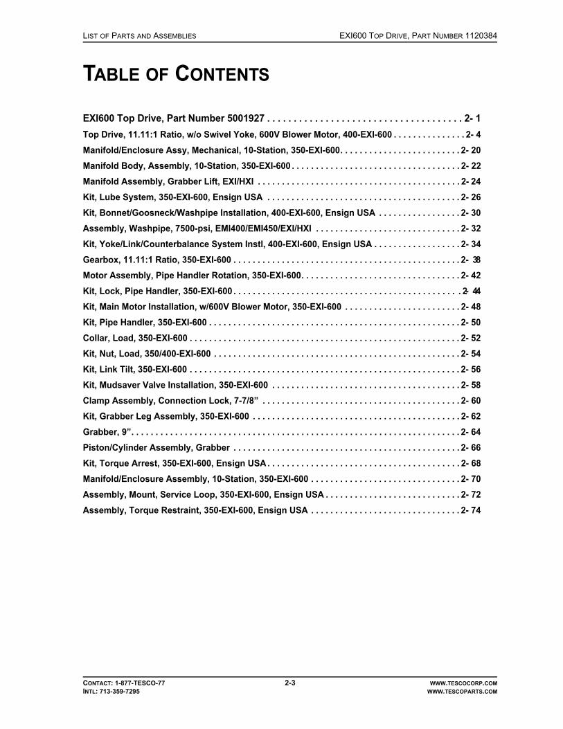
LIST OF PARTS AND ASSEMBLIES EXI600 TOP DRIVE, PART NUMBER 1120384
CONTACT: 1-877-TESCO-77 2-3 WWW.TESCOCORP.COMINTL: 713-359-7295 WWW.TESCOPARTS.COM
TABLE OF CONTENTS
EXI600 Top Drive, Part Number 5001927 . . . . . . . . . . . . . . . . . . . . . . . . . . . . . . . . . . . . . 2- 1Top Drive, 11.11:1 Ratio, w/o Swivel Yoke, 600V Blower Motor, 400-EXI-600 . . . . . . . . . . . . . . . 2- 4Manifold/Enclosure Assy, Mechanical, 10-Station, 350-EXI-600. . . . . . . . . . . . . . . . . . . . . . . . . 2- 20Manifold Body, Assembly, 10-Station, 350-EXI-600 . . . . . . . . . . . . . . . . . . . . . . . . . . . . . . . . . . . 2- 22Manifold Assembly, Grabber Lift, EXI/HXI . . . . . . . . . . . . . . . . . . . . . . . . . . . . . . . . . . . . . . . . . . 2- 24Kit, Lube System, 350-EXI-600, Ensign USA . . . . . . . . . . . . . . . . . . . . . . . . . . . . . . . . . . . . . . . . 2- 26Kit, Bonnet/Goosneck/Washpipe Installation, 400-EXI-600, Ensign USA . . . . . . . . . . . . . . . . . 2- 30Assembly, Washpipe, 7500-psi, EMI400/EMI450/EXI/HXI . . . . . . . . . . . . . . . . . . . . . . . . . . . . . . 2- 32Kit, Yoke/Link/Counterbalance System Instl, 400-EXI-600, Ensign USA . . . . . . . . . . . . . . . . . . 2- 34Gearbox, 11.11:1 Ratio, 350-EXI-600 . . . . . . . . . . . . . . . . . . . . . . . . . . . . . . . . . . . . . . . . . . . . . . . 2- 38Motor Assembly, Pipe Handler Rotation, 350-EXI-600. . . . . . . . . . . . . . . . . . . . . . . . . . . . . . . . . 2- 42Kit, Lock, Pipe Handler, 350-EXI-600 . . . . . . . . . . . . . . . . . . . . . . . . . . . . . . . . . . . . . . . . . . . . . . . 2- 44Kit, Main Motor Installation, w/600V Blower Motor, 350-EXI-600 . . . . . . . . . . . . . . . . . . . . . . . . 2- 48Kit, Pipe Handler, 350-EXI-600 . . . . . . . . . . . . . . . . . . . . . . . . . . . . . . . . . . . . . . . . . . . . . . . . . . . . 2- 50Collar, Load, 350-EXI-600 . . . . . . . . . . . . . . . . . . . . . . . . . . . . . . . . . . . . . . . . . . . . . . . . . . . . . . . . 2- 52Kit, Nut, Load, 350/400-EXI-600 . . . . . . . . . . . . . . . . . . . . . . . . . . . . . . . . . . . . . . . . . . . . . . . . . . . 2- 54Kit, Link Tilt, 350-EXI-600 . . . . . . . . . . . . . . . . . . . . . . . . . . . . . . . . . . . . . . . . . . . . . . . . . . . . . . . . 2- 56Kit, Mudsaver Valve Installation, 350-EXI-600 . . . . . . . . . . . . . . . . . . . . . . . . . . . . . . . . . . . . . . . 2- 58Clamp Assembly, Connection Lock, 7-7/8” . . . . . . . . . . . . . . . . . . . . . . . . . . . . . . . . . . . . . . . . . 2- 60Kit, Grabber Leg Assembly, 350-EXI-600 . . . . . . . . . . . . . . . . . . . . . . . . . . . . . . . . . . . . . . . . . . . 2- 62Grabber, 9”. . . . . . . . . . . . . . . . . . . . . . . . . . . . . . . . . . . . . . . . . . . . . . . . . . . . . . . . . . . . . . . . . . . . 2- 64Piston/Cylinder Assembly, Grabber . . . . . . . . . . . . . . . . . . . . . . . . . . . . . . . . . . . . . . . . . . . . . . . 2- 66Kit, Torque Arrest, 350-EXI-600, Ensign USA . . . . . . . . . . . . . . . . . . . . . . . . . . . . . . . . . . . . . . . . 2- 68Manifold/Enclosure Assembly, 10-Station, 350-EXI-600 . . . . . . . . . . . . . . . . . . . . . . . . . . . . . . . 2- 70Assembly, Mount, Service Loop, 350-EXI-600, Ensign USA . . . . . . . . . . . . . . . . . . . . . . . . . . . . 2- 72Assembly, Torque Restraint, 350-EXI-600, Ensign USA . . . . . . . . . . . . . . . . . . . . . . . . . . . . . . . 2- 74

EXI600 TOP DRIVE, PART NUMBER 5001927 LIST OF PARTS AND ASSEMBLIES
CONTACT: 1-877-TESCO-77 2-4 WWW.TESCOCORP.COMINTL: 713-359-7295 WWW.TESCOPARTS.COM
TOP DRIVE, 11.11:1 RATIO, W/O SWIVEL YOKE, 600V BLOWER MOTOR, 400-EXI-600

LIST OF PARTS AND ASSEMBLIES EXI600 TOP DRIVE, PART NUMBER 5001927
CONTACT: 1-877-TESCO-77 2-5 WWW.TESCOCORP.COMINTL: 713-359-7295 WWW.TESCOPARTS.COM
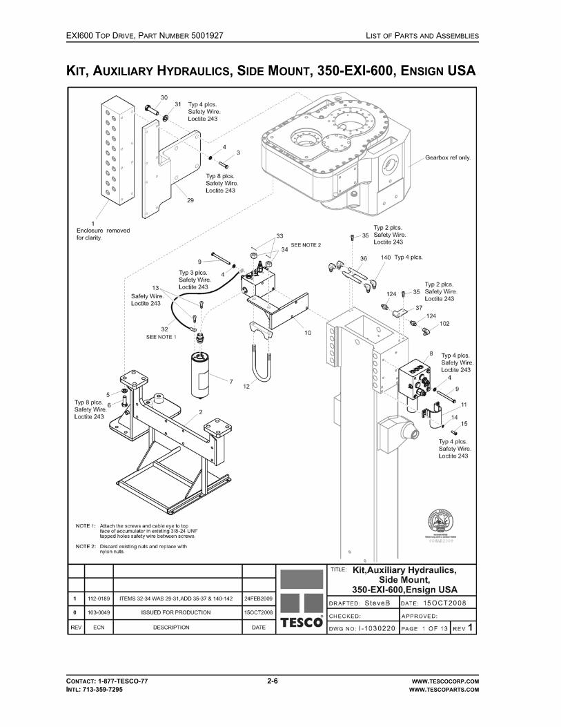
EXI600 TOP DRIVE, PART NUMBER 5001927 LIST OF PARTS AND ASSEMBLIES
CONTACT: 1-877-TESCO-77 2-6 WWW.TESCOCORP.COMINTL: 713-359-7295 WWW.TESCOPARTS.COM
KIT, AUXILIARY HYDRAULICS, SIDE MOUNT, 350-EXI-600, ENSIGN USA
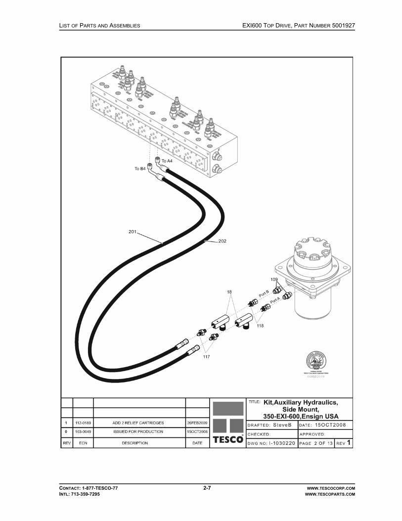
LIST OF PARTS AND ASSEMBLIES EXI600 TOP DRIVE, PART NUMBER 5001927
CONTACT: 1-877-TESCO-77 2-7 WWW.TESCOCORP.COMINTL: 713-359-7295 WWW.TESCOPARTS.COM

EXI600 TOP DRIVE, PART NUMBER 5001927 LIST OF PARTS AND ASSEMBLIES
CONTACT: 1-877-TESCO-77 2-8 WWW.TESCOCORP.COMINTL: 713-359-7295 WWW.TESCOPARTS.COM

LIST OF PARTS AND ASSEMBLIES EXI600 TOP DRIVE, PART NUMBER 5001927
CONTACT: 1-877-TESCO-77 2-9 WWW.TESCOCORP.COMINTL: 713-359-7295 WWW.TESCOPARTS.COM

EXI600 TOP DRIVE, PART NUMBER 5001927 LIST OF PARTS AND ASSEMBLIES
CONTACT: 1-877-TESCO-77 2-10 WWW.TESCOCORP.COMINTL: 713-359-7295 WWW.TESCOPARTS.COM

LIST OF PARTS AND ASSEMBLIES EXI600 TOP DRIVE, PART NUMBER 5001927
CONTACT: 1-877-TESCO-77 2-11 WWW.TESCOCORP.COMINTL: 713-359-7295 WWW.TESCOPARTS.COM
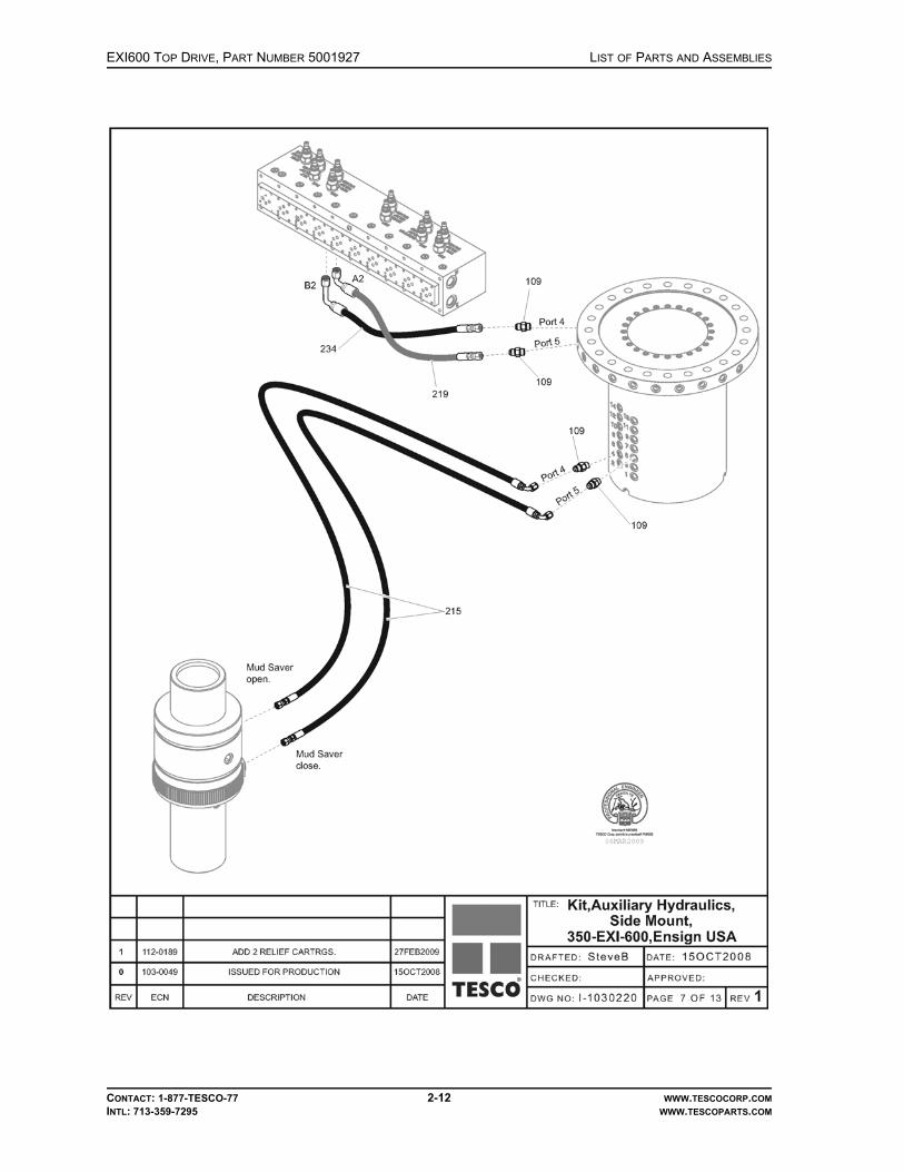
EXI600 TOP DRIVE, PART NUMBER 5001927 LIST OF PARTS AND ASSEMBLIES
CONTACT: 1-877-TESCO-77 2-12 WWW.TESCOCORP.COMINTL: 713-359-7295 WWW.TESCOPARTS.COM

LIST OF PARTS AND ASSEMBLIES EXI600 TOP DRIVE, PART NUMBER 5001927
CONTACT: 1-877-TESCO-77 2-13 WWW.TESCOCORP.COMINTL: 713-359-7295 WWW.TESCOPARTS.COM

EXI600 TOP DRIVE, PART NUMBER 5001927 LIST OF PARTS AND ASSEMBLIES
CONTACT: 1-877-TESCO-77 2-14 WWW.TESCOCORP.COMINTL: 713-359-7295 WWW.TESCOPARTS.COM

LIST OF PARTS AND ASSEMBLIES EXI600 TOP DRIVE, PART NUMBER 5001927
CONTACT: 1-877-TESCO-77 2-15 WWW.TESCOCORP.COMINTL: 713-359-7295 WWW.TESCOPARTS.COM

EXI600 TOP DRIVE, PART NUMBER 5001927 LIST OF PARTS AND ASSEMBLIES
CONTACT: 1-877-TESCO-77 2-16 WWW.TESCOCORP.COMINTL: 713-359-7295 WWW.TESCOPARTS.COM
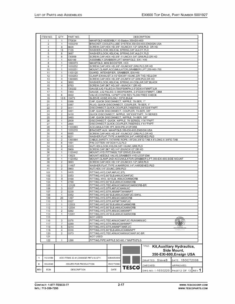
LIST OF PARTS AND ASSEMBLIES EXI600 TOP DRIVE, PART NUMBER 5001927
CONTACT: 1-877-TESCO-77 2-17 WWW.TESCOCORP.COMINTL: 713-359-7295 WWW.TESCOPARTS.COM

EXI600 TOP DRIVE, PART NUMBER 5001927 LIST OF PARTS AND ASSEMBLIES
CONTACT: 1-877-TESCO-77 2-18 WWW.TESCOCORP.COMINTL: 713-359-7295 WWW.TESCOPARTS.COM

LIST OF PARTS AND ASSEMBLIES EXI600 TOP DRIVE, PART NUMBER 5001927
CONTACT: 1-877-TESCO-77 2-19 WWW.TESCOCORP.COMINTL: 713-359-7295 WWW.TESCOPARTS.COM
This page has been left blank intentionally.

EXI600 TOP DRIVE, PART NUMBER 5001927 LIST OF PARTS AND ASSEMBLIES
CONTACT: 1-877-TESCO-77 2-20 WWW.TESCOCORP.COMINTL: 713-359-7295 WWW.TESCOPARTS.COM
MANIFOLD/ENCLOSURE ASSY, MECHANICAL, 10-STATION, 350-EXI-600

LIST OF PARTS AND ASSEMBLIES EXI600 TOP DRIVE, PART NUMBER 5001927
CONTACT: 1-877-TESCO-77 2-21 WWW.TESCOCORP.COMINTL: 713-359-7295 WWW.TESCOPARTS.COM
This page has been left blank intentionally.

EXI600 TOP DRIVE, PART NUMBER 5001927 LIST OF PARTS AND ASSEMBLIES
CONTACT: 1-877-TESCO-77 2-22 WWW.TESCOCORP.COMINTL: 713-359-7295 WWW.TESCOPARTS.COM
MANIFOLD BODY, ASSEMBLY, 10-STATION, 350-EXI-600

LIST OF PARTS AND ASSEMBLIES EXI600 TOP DRIVE, PART NUMBER 5001927
CONTACT: 1-877-TESCO-77 2-23 WWW.TESCOCORP.COMINTL: 713-359-7295 WWW.TESCOPARTS.COM

EXI600 TOP DRIVE, PART NUMBER 5001927 LIST OF PARTS AND ASSEMBLIES
©TESCO CORPORATION, 20102-24
MANIFOLD ASSEMBLY, GRABBER LIFT, EXI/HXI

LIST OF PARTS AND ASSEMBLIES EXI600 TOP DRIVE, PART NUMBER 5001927
CONTACT: 1-877-TESCO-77 2-25 WWW.TESCOCORP.COMINTL: 713-359-7295 WWW.TESCOPARTS.COM
This page has been left blank intentionally.

EXI600 TOP DRIVE, PART NUMBER 5001927 LIST OF PARTS AND ASSEMBLIES
CONTACT: 1-877-TESCO-77 2-26 WWW.TESCOCORP.COMINTL: 713-359-7295 WWW.TESCOPARTS.COM
KIT, LUBE SYSTEM, 350-EXI-600, ENSIGN USA

LIST OF PARTS AND ASSEMBLIES EXI600 TOP DRIVE, PART NUMBER 5001927
CONTACT: 1-877-TESCO-77 2-27 WWW.TESCOCORP.COMINTL: 713-359-7295 WWW.TESCOPARTS.COM

EXI600 TOP DRIVE, PART NUMBER 5001927 LIST OF PARTS AND ASSEMBLIES
CONTACT: 1-877-TESCO-77 2-28 WWW.TESCOCORP.COMINTL: 713-359-7295 WWW.TESCOPARTS.COM

LIST OF PARTS AND ASSEMBLIES EXI600 TOP DRIVE, PART NUMBER 5001927
CONTACT: 1-877-TESCO-77 2-29 WWW.TESCOCORP.COMINTL: 713-359-7295 WWW.TESCOPARTS.COM
This page has been left blank intentionally.

EXI600 TOP DRIVE, PART NUMBER 5001927 LIST OF PARTS AND ASSEMBLIES
CONTACT: 1-877-TESCO-77 2-30 WWW.TESCOCORP.COMINTL: 713-359-7295 WWW.TESCOPARTS.COM
KIT, BONNET/GOOSNECK/WASHPIPE INSTALLATION, 400-EXI-600, ENSIGN USA

LIST OF PARTS AND ASSEMBLIES EXI600 TOP DRIVE, PART NUMBER 5001927
CONTACT: 1-877-TESCO-77 2-31 WWW.TESCOCORP.COMINTL: 713-359-7295 WWW.TESCOPARTS.COM

EXI600 TOP DRIVE, PART NUMBER 5001927 LIST OF PARTS AND ASSEMBLIES
CONTACT: 1-877-TESCO-77 2-32 WWW.TESCOCORP.COMINTL: 713-359-7295 WWW.TESCOPARTS.COM
ASSEMBLY, WASHPIPE, 7500-PSI, EMI400/EMI450/EXI/HXI

LIST OF PARTS AND ASSEMBLIES EXI600 TOP DRIVE, PART NUMBER 5001927
CONTACT: 1-877-TESCO-77 2-33 WWW.TESCOCORP.COMINTL: 713-359-7295 WWW.TESCOPARTS.COM
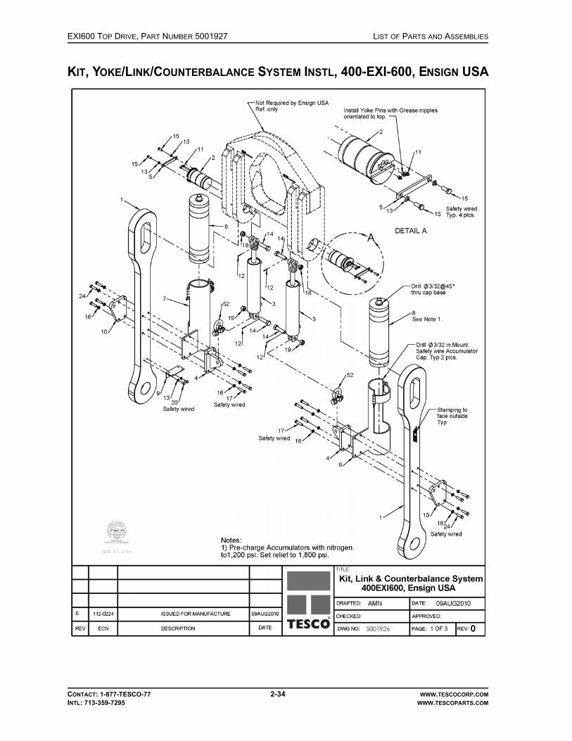
EXI600 TOP DRIVE, PART NUMBER 5001927 LIST OF PARTS AND ASSEMBLIES
CONTACT: 1-877-TESCO-77 2-34 WWW.TESCOCORP.COMINTL: 713-359-7295 WWW.TESCOPARTS.COM
KIT, YOKE/LINK/COUNTERBALANCE SYSTEM INSTL, 400-EXI-600, ENSIGN USA

LIST OF PARTS AND ASSEMBLIES EXI600 TOP DRIVE, PART NUMBER 5001927
CONTACT: 1-877-TESCO-77 2-35 WWW.TESCOCORP.COMINTL: 713-359-7295 WWW.TESCOPARTS.COM
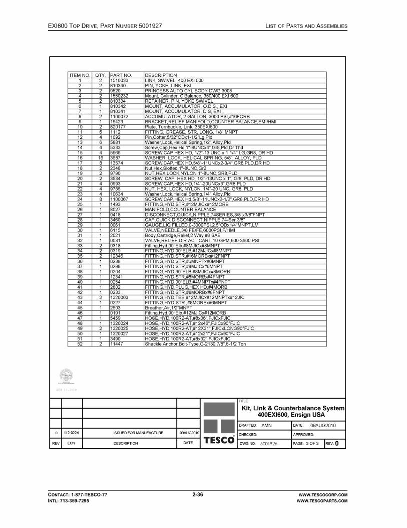
EXI600 TOP DRIVE, PART NUMBER 5001927 LIST OF PARTS AND ASSEMBLIES
CONTACT: 1-877-TESCO-77 2-36 WWW.TESCOCORP.COMINTL: 713-359-7295 WWW.TESCOPARTS.COM

LIST OF PARTS AND ASSEMBLIES EXI600 TOP DRIVE, PART NUMBER 5001927
CONTACT: 1-877-TESCO-77 2-37 WWW.TESCOCORP.COMINTL: 713-359-7295 WWW.TESCOPARTS.COM
This page has been left blank intentionally.

EXI600 TOP DRIVE, PART NUMBER 5001927 LIST OF PARTS AND ASSEMBLIES
CONTACT: 1-877-TESCO-77 2-38 WWW.TESCOCORP.COMINTL: 713-359-7295 WWW.TESCOPARTS.COM
GEARBOX, 11.11:1 RATIO, 350-EXI-600

LIST OF PARTS AND ASSEMBLIES EXI600 TOP DRIVE, PART NUMBER 5001927
CONTACT: 1-877-TESCO-77 2-39 WWW.TESCOCORP.COMINTL: 713-359-7295 WWW.TESCOPARTS.COM

EXI600 TOP DRIVE, PART NUMBER 5001927 LIST OF PARTS AND ASSEMBLIES
CONTACT: 1-877-TESCO-77 2-40 WWW.TESCOCORP.COMINTL: 713-359-7295 WWW.TESCOPARTS.COM

LIST OF PARTS AND ASSEMBLIES EXI600 TOP DRIVE, PART NUMBER 5001927
CONTACT: 1-877-TESCO-77 2-41 WWW.TESCOCORP.COMINTL: 713-359-7295 WWW.TESCOPARTS.COM
This page has been left blank intentionally.
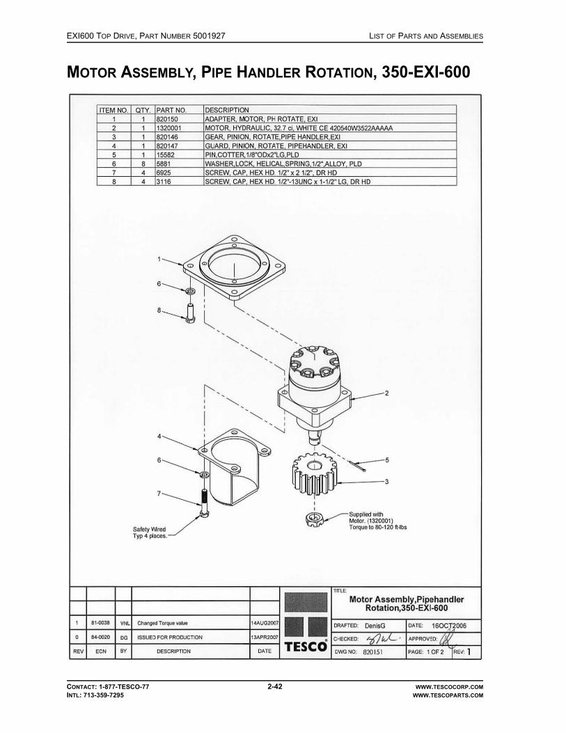
EXI600 TOP DRIVE, PART NUMBER 5001927 LIST OF PARTS AND ASSEMBLIES
CONTACT: 1-877-TESCO-77 2-42 WWW.TESCOCORP.COMINTL: 713-359-7295 WWW.TESCOPARTS.COM
MOTOR ASSEMBLY, PIPE HANDLER ROTATION, 350-EXI-600

LIST OF PARTS AND ASSEMBLIES EXI600 TOP DRIVE, PART NUMBER 5001927
CONTACT: 1-877-TESCO-77 2-43 WWW.TESCOCORP.COMINTL: 713-359-7295 WWW.TESCOPARTS.COM

EXI600 TOP DRIVE, PART NUMBER 5001927 LIST OF PARTS AND ASSEMBLIES
CONTACT: 1-877-TESCO-77 2-44 WWW.TESCOCORP.COMINTL: 713-359-7295 WWW.TESCOPARTS.COM
KIT, LOCK, PIPE HANDLER, 350-EXI-600

LIST OF PARTS AND ASSEMBLIES EXI600 TOP DRIVE, PART NUMBER 5001927
CONTACT: 1-877-TESCO-77 2-45 WWW.TESCOCORP.COMINTL: 713-359-7295 WWW.TESCOPARTS.COM

EXI600 TOP DRIVE, PART NUMBER 5001927 LIST OF PARTS AND ASSEMBLIES
CONTACT: 1-877-TESCO-77 2-46 WWW.TESCOCORP.COMINTL: 713-359-7295 WWW.TESCOPARTS.COM

LIST OF PARTS AND ASSEMBLIES EXI600 TOP DRIVE, PART NUMBER 5001927
CONTACT: 1-877-TESCO-77 2-47 WWW.TESCOCORP.COMINTL: 713-359-7295 WWW.TESCOPARTS.COM
This page has been left blank intentionally.

EXI600 TOP DRIVE, PART NUMBER 5001927 LIST OF PARTS AND ASSEMBLIES
CONTACT: 1-877-TESCO-77 2-48 WWW.TESCOCORP.COMINTL: 713-359-7295 WWW.TESCOPARTS.COM
KIT, MAIN MOTOR INSTALLATION, W/600V BLOWER MOTOR, 350-EXI-600

LIST OF PARTS AND ASSEMBLIES EXI600 TOP DRIVE, PART NUMBER 5001927
CONTACT: 1-877-TESCO-77 2-49 WWW.TESCOCORP.COMINTL: 713-359-7295 WWW.TESCOPARTS.COM
This page has been left blank intentionally.

EXI600 TOP DRIVE, PART NUMBER 5001927 LIST OF PARTS AND ASSEMBLIES
CONTACT: 1-877-TESCO-77 2-50 WWW.TESCOCORP.COMINTL: 713-359-7295 WWW.TESCOPARTS.COM
KIT, PIPE HANDLER, 350-EXI-600

LIST OF PARTS AND ASSEMBLIES EXI600 TOP DRIVE, PART NUMBER 5001927
CONTACT: 1-877-TESCO-77 2-51 WWW.TESCOCORP.COMINTL: 713-359-7295 WWW.TESCOPARTS.COM

EXI600 TOP DRIVE, PART NUMBER 5001927 LIST OF PARTS AND ASSEMBLIES
CONTACT: 1-877-TESCO-77 2-52 WWW.TESCOCORP.COMINTL: 713-359-7295 WWW.TESCOPARTS.COM
COLLAR, LOAD, 350-EXI-600

LIST OF PARTS AND ASSEMBLIES EXI600 TOP DRIVE, PART NUMBER 5001927
CONTACT: 1-877-TESCO-77 2-53 WWW.TESCOCORP.COMINTL: 713-359-7295 WWW.TESCOPARTS.COM
This page has been left blank intentionally.

EXI600 TOP DRIVE, PART NUMBER 5001927 LIST OF PARTS AND ASSEMBLIES
CONTACT: 1-877-TESCO-77 2-54 WWW.TESCOCORP.COMINTL: 713-359-7295 WWW.TESCOPARTS.COM
KIT, NUT, LOAD, 350/400-EXI-600

LIST OF PARTS AND ASSEMBLIES EXI600 TOP DRIVE, PART NUMBER 5001927
CONTACT: 1-877-TESCO-77 2-55 WWW.TESCOCORP.COMINTL: 713-359-7295 WWW.TESCOPARTS.COM
This page has been left blank intentionally.

EXI600 TOP DRIVE, PART NUMBER 5001927 LIST OF PARTS AND ASSEMBLIES
CONTACT: 1-877-TESCO-77 2-56 WWW.TESCOCORP.COMINTL: 713-359-7295 WWW.TESCOPARTS.COM
KIT, LINK TILT, 350-EXI-600

LIST OF PARTS AND ASSEMBLIES EXI600 TOP DRIVE, PART NUMBER 5001927
CONTACT: 1-877-TESCO-77 2-57 WWW.TESCOCORP.COMINTL: 713-359-7295 WWW.TESCOPARTS.COM
This page has been left blank intentionally.
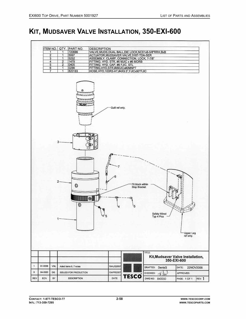
EXI600 TOP DRIVE, PART NUMBER 5001927 LIST OF PARTS AND ASSEMBLIES
CONTACT: 1-877-TESCO-77 2-58 WWW.TESCOCORP.COMINTL: 713-359-7295 WWW.TESCOPARTS.COM
KIT, MUDSAVER VALVE INSTALLATION, 350-EXI-600

LIST OF PARTS AND ASSEMBLIES EXI600 TOP DRIVE, PART NUMBER 5001927
CONTACT: 1-877-TESCO-77 2-59 WWW.TESCOCORP.COMINTL: 713-359-7295 WWW.TESCOPARTS.COM
This page has been left blank intentionally.

EXI600 TOP DRIVE, PART NUMBER 5001927 LIST OF PARTS AND ASSEMBLIES
CONTACT: 1-877-TESCO-77 2-60 WWW.TESCOCORP.COMINTL: 713-359-7295 WWW.TESCOPARTS.COM
CLAMP ASSEMBLY, CONNECTION LOCK, 7-7/8”

LIST OF PARTS AND ASSEMBLIES EXI600 TOP DRIVE, PART NUMBER 5001927
CONTACT: 1-877-TESCO-77 2-61 WWW.TESCOCORP.COMINTL: 713-359-7295 WWW.TESCOPARTS.COM
This page has been left blank intentionally.
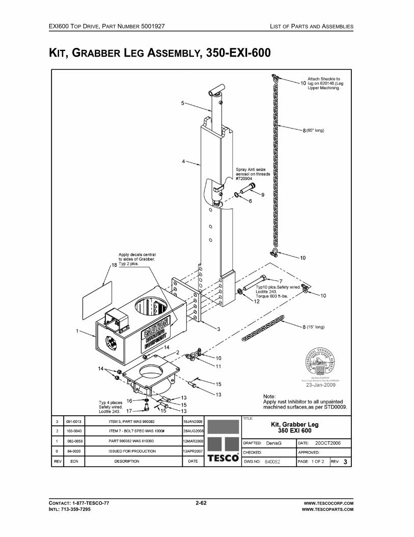
EXI600 TOP DRIVE, PART NUMBER 5001927 LIST OF PARTS AND ASSEMBLIES
CONTACT: 1-877-TESCO-77 2-62 WWW.TESCOCORP.COMINTL: 713-359-7295 WWW.TESCOPARTS.COM
KIT, GRABBER LEG ASSEMBLY, 350-EXI-600

LIST OF PARTS AND ASSEMBLIES EXI600 TOP DRIVE, PART NUMBER 5001927
CONTACT: 1-877-TESCO-77 2-63 WWW.TESCOCORP.COMINTL: 713-359-7295 WWW.TESCOPARTS.COM
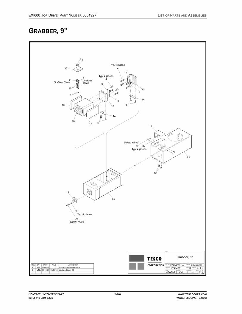
EXI600 TOP DRIVE, PART NUMBER 5001927 LIST OF PARTS AND ASSEMBLIES
CONTACT: 1-877-TESCO-77 2-64 WWW.TESCOCORP.COMINTL: 713-359-7295 WWW.TESCOPARTS.COM
GRABBER, 9”

LIST OF PARTS AND ASSEMBLIES EXI600 TOP DRIVE, PART NUMBER 5001927
CONTACT: 1-877-TESCO-77 2-65 WWW.TESCOCORP.COMINTL: 713-359-7295 WWW.TESCOPARTS.COM

EXI600 TOP DRIVE, PART NUMBER 5001927 LIST OF PARTS AND ASSEMBLIES
CONTACT: 1-877-TESCO-77 2-66 WWW.TESCOCORP.COMINTL: 713-359-7295 WWW.TESCOPARTS.COM
PISTON/CYLINDER ASSEMBLY, GRABBER

LIST OF PARTS AND ASSEMBLIES EXI600 TOP DRIVE, PART NUMBER 5001927
CONTACT: 1-877-TESCO-77 2-67 WWW.TESCOCORP.COMINTL: 713-359-7295 WWW.TESCOPARTS.COM

EXI600 TOP DRIVE, PART NUMBER 5001927 LIST OF PARTS AND ASSEMBLIES
CONTACT: 1-877-TESCO-77 2-68 WWW.TESCOCORP.COMINTL: 713-359-7295 WWW.TESCOPARTS.COM
KIT, TORQUE ARREST, 350-EXI-600, ENSIGN USA

LIST OF PARTS AND ASSEMBLIES EXI600 TOP DRIVE, PART NUMBER 5001927
CONTACT: 1-877-TESCO-77 2-69 WWW.TESCOCORP.COMINTL: 713-359-7295 WWW.TESCOPARTS.COM
This page has been left blank intentionally.

LIST OF PARTS AND ASSEMBLIES EXI600 TOP DRIVE, PART NUMBER 5001927
CONTACT: 1-877-TESCO-77 2-70 WWW.TESCOCORP.COMINTL: 713-359-7295 WWW.TESCOPARTS.COM
MANIFOLD/ENCLOSURE ASSEMBLY, 10-STATION, 350-EXI-600

EXI600 TOP DRIVE, PART NUMBER 5001927 LIST OF PARTS AND ASSEMBLIES
CONTACT: 1-877-TESCO-77 2-71 WWW.TESCOCORP.COMINTL: 713-359-7295 WWW.TESCOPARTS.COM
This page has been left blank intentionally.

LIST OF PARTS AND ASSEMBLIES EXI600 TOP DRIVE, PART NUMBER 5001927
CONTACT: 1-877-TESCO-77 2-72 WWW.TESCOCORP.COMINTL: 713-359-7295 WWW.TESCOPARTS.COM
ASSEMBLY, MOUNT, SERVICE LOOP, 350-EXI-600, ENSIGN USA

EXI600 TOP DRIVE, PART NUMBER 5001927 LIST OF PARTS AND ASSEMBLIES
CONTACT: 1-877-TESCO-77 2-73 WWW.TESCOCORP.COMINTL: 713-359-7295 WWW.TESCOPARTS.COM

EXI600 TOP DRIVE, PART NUMBER 5001927 LIST OF PARTS AND ASSEMBLIES
CONTACT: 1-877-TESCO-77 2-74 WWW.TESCOCORP.COMINTL: 713-359-7295 WWW.TESCOPARTS.COM
ASSEMBLY, TORQUE RESTRAINT, 350-EXI-600, ENSIGN USA

EXI600 TOP DRIVE, PART NUMBER 5001927 LIST OF PARTS AND ASSEMBLIES
CONTACT: 1-877-TESCO-77 2-75 WWW.TESCOCORP.COMINTL: 713-359-7295 WWW.TESCOPARTS.COM
This page has been left blank intentionally.

LIST OF PARTS AND ASSEMBLIES ENGINEERING SIGN-OFF
CONTACT: 1-877-TESCO-77 WWW.TESCOCORP.COM
INTL: 713-359-7295 WWW.TESCOPARTS.COM
ENGINEERING SIGN-OFF
This sign-off sheet indicates that this document has been approved for release by the Engineering Department at TESCO.
Document Completed By Signature Date Signed
Document Reviewed/Approved Date Signed
chane
Typewritten Text
Edward ChanAug. 13, 2010
chane
Typewritten Text
yef
Typewritten Text
August 13, 2010
yef
Typewritten Text
yef
Typewritten Text

ENGINEERING SIGN-OFF LIST OF PARTS AND ASSEMBLIES
CONTACT: 1-877-TESCO-77 WWW.TESCOCORP.COM
INTL: 713-359-7295 WWW.TESCOPARTS.COM
This page has been left blank intentionally.

alamk
Typewritten Text
June 18, 2010
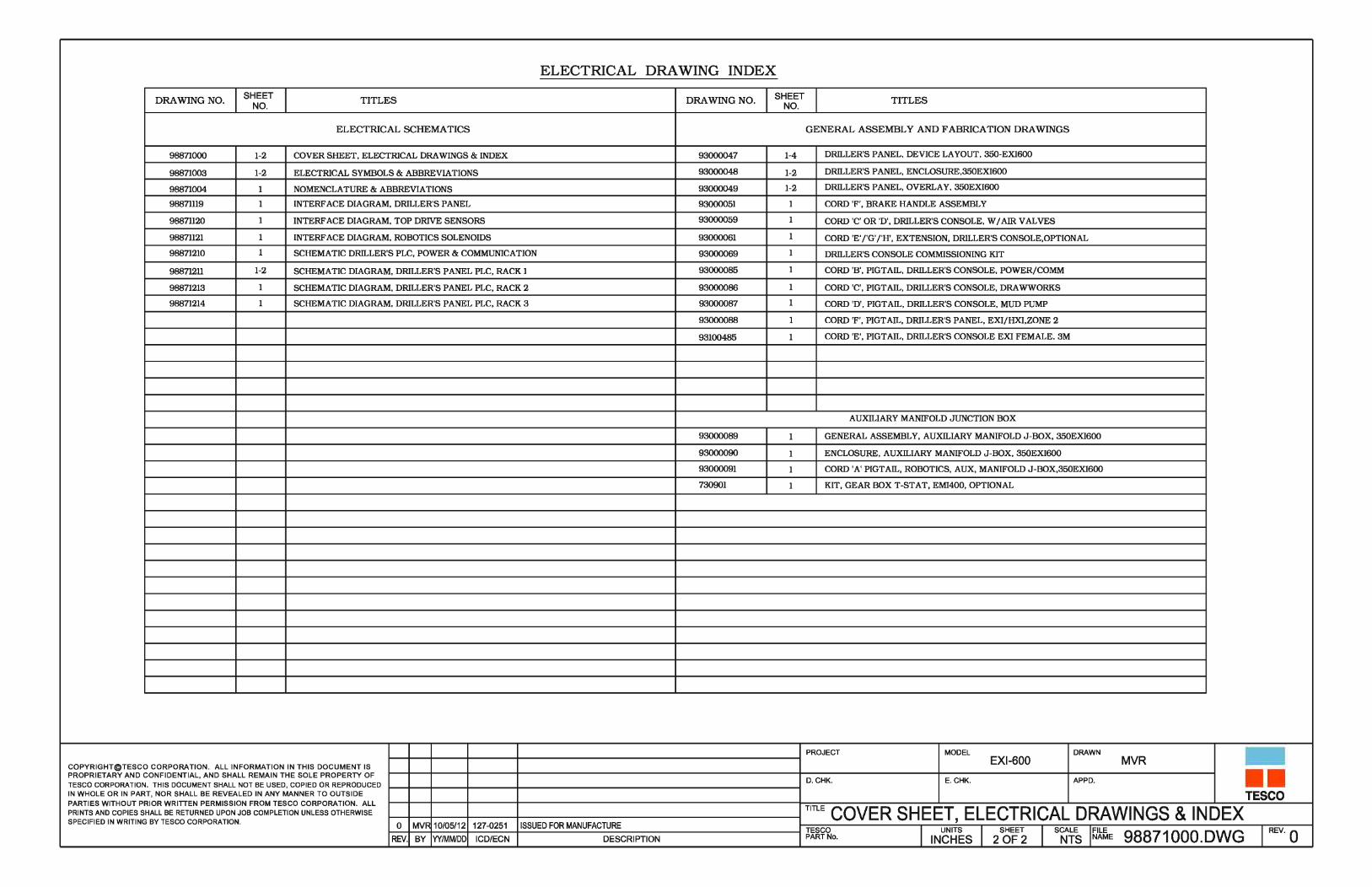
alamk
Typewritten Text
June 18, 2010

alamk
Typewritten Text
June 18, 2010

alamk
Typewritten Text
June 18, 2010
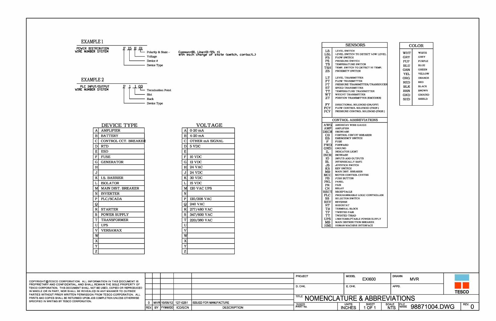
alamk
Typewritten Text
June 18, 2010

alamk
Typewritten Text
June 18. 2010

alamk
Typewritten Text
June 18, 2010

alamk
Typewritten Text
June 18, 2010
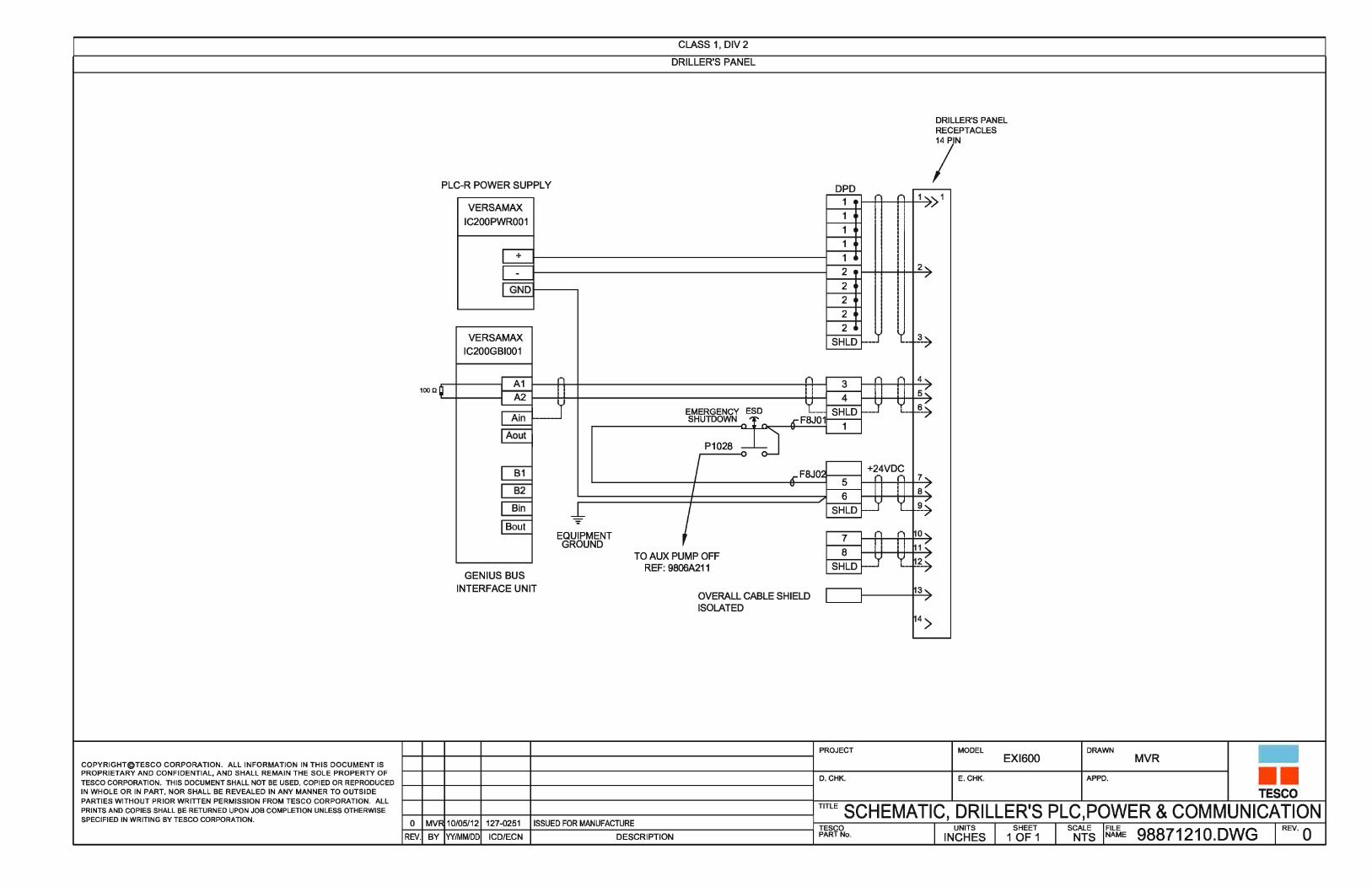
alamk
Typewritten Text
June 18, 2010

alamk
Typewritten Text
June 18, 2010

alamk
Typewritten Text
June 18, 2010

alamk
Typewritten Text
June 18, 2010

alamk
Typewritten Text
June 18, 2010

fallenm
Typewritten Text
27-Nov-2009

fallenm
Typewritten Text
27-Nov-2009

lerouh
Text Box
27 Oct 08

1 GQH 040623 6116 Add low temperature fluid specification
0 GHH 021217 Initial Release
Rev: By: Date: ICD: Description:
COPYRIGHT © TESCO CORPORATION. All information in this document is proprietary and confidential and shall remain the sole property of TESCO
Corporation. This document shall not be used, copied or reproduced in whole or in part, nor shall be revealed in any manner to outside parties without prior written
permission from TESCO Corporation. All prints and copies shall be returned upon job completion unless otherwise specified in writing by TESCO Corporation.
Page 1 of 1
Engineering Memorandum EM No: EM000041 Rev: 1 Date: June 17, 2004
Description: Specification – Hydraulic Fluid
Products Division 4930 – 74th Avenue SE
Calgary, Alberta T2C 3C9
Phone: (403) 301-4200
Fax: (403) 253-3578
Web: www.tescocorp.com
Originator: Gary Hansen
Date: September 27, 2002
Checked:
Date:
Approved:
Date:
Scope:
This EM specifies hydraulic fluid suitable for high and low ambient temperature applications (open and closed
loop hydraulic circuits). Hydraulic fluid listed in the left column is the first choice for all applications. Synthetic
automatic transmission fluid (ATF) listed in the right column is the alternative choice for electrical top drive
open loop application at very low ambient environment.
Specification:
Description Premium Anti-wear Hydraulic Fluid Synthetic Automatic Transmission
Fluid
ISO Grade 68 N/A
Viscosity Index 90 or higher per ASTM D-2270 182 or higher per ASTM D-2270
Ambient Temperature Range -20 oC to 50
oC -50
oC to -20
oC
Operating Temperature Range 0 oC to 85
oC -40
oC to 120
oC
Flash Point 160 oC or higher 222
oC or higher
Pour Point -30 oC or lower -56
oC or lower
Kinematic Viscosity 68 cST ± 5cST @ 40 oC
6.4 cST + 2cST @ 100 oC
36 cST ± 3cST @ 40 oC
7.5 cST ± 1cST @ 100 oC
Other Features � Oxidation and thermal stability
for long life
� Anti-wear properties and
extreme pressure characteristics
for protection against wear and
scouring
� Anti-foam, rust and
anticorrosion additives
� Elastomer compatibility for
extended seal and gasket life
� Oxidation and thermal stability
for long life
� Anti-wear protection
� Elastomer compatibility for
extended seal and gasket life
Approved Oils Mohawk HVI 68; Imperial Oil Univis
68; Shell Telus T68; PetroCanada
Harmony HVI 68
Amsoil Synthetic ATF

0 GHH 03/10/27 Initial Release 1 VNL 09/05/05 072-0102 Changed Description
Rev: By: Date: ICD: Description:
COPYRIGHT © TESCO CORPORATION. All information in this document is proprietary and confidential and shall remain the sole property of TESCO Corporation. This document shall not be used, copied or reproduced in whole or in part, nor shall be revealed in any manner to outside parties without prior written permission from TESCO Corporation. All prints and copies shall be returned upon job completion unless otherwise specified in writing by TESCO Corporation.
Page 1 of 1
Engineering Memorandum
Tesco Corporation 5616 –804th Avenue SE Calgary, Alberta T2C 4N5 Phone: (403) 723-7902 Fax: (403) 723-7826 Web: www.tescocorp.com
EM No: EM000046 Rev: 1 Date: October 27, 2003 Description: Specification – Lube Oil, Gearbox, Synthetic, Top Drive, EMI-400/ECI-900/ECI-1350
Originator: Gary Hansen Date: October 27, 2003
Checked: Date:
Approved: Date:
Scope: Lube oil for electrically driven top drive gearbox where high input gear tooth velocities require a high performance lubricant. Specification: 1. Premium multipurpose extreme pressure gearbox synthetic lubricant
2. ISO Grade 75W90 3. Viscosity Index 145 minimum per ASTM D-445
4. Flash Point 140oC (minimum) 5. Pour Point -35oC (maximum)
6. Kinematic Viscosity 120 cST (minimum) @ 40oC 16 cST (minimum) @ 100oC
7. Wear protection properties for heavily loaded gear teeth, EP properties, protection against wear and
scouring, anti-foam performance, demulsibility, anti-rust and anti-corrosion protection.
8. Elastomer compatibility for extended seal and gasket life.
9. Approved for API GL-5. 10. Sample Fluids that meet this specification: Shell Spirax 75W90, Chevron RPM Synthetic 75W90, Texaco
Syn Star 75W90 Full Synthetic.
erasmusp
Typewritten Text
15 May 2009

3 LW 06/04/24 LSW-136 Add EMI 400 and revise D4P hydraulic oil. 4 JYZ 07/04/19 111-0038 General Revision 5 VNL 09/05/05 072-0102 General Revision
Rev: By: Date: ICD/ECN: Description:
COPYRIGHT © TESCO CORPORATION. All information in this document is proprietary and confidential and shall remain the sole property of TESCO Corporation. This document shall not be used, copied or reproduced in whole or in part, nor shall be revealed in any manner to outside parties without prior written permission from TESCO Corporation. All prints and copies shall be returned upon job completion unless otherwise specified in writing by TESCO Corporation.
Page 1 of 7
Engineering Memorandum
Tesco Corporation 5616 –80th Avenue SE Calgary, Alberta T2C 4N5 Phone: (403) 723-7902 Fax: (403) 723-7826 Web: www.tescocorp.com
EM No: EM000113 Rev: 5 Date: Sep. 1, 2004 Description: Fluid Specification and Capacity Charts for Top Drive Systems
Originator: Louis Wen Date: Sep. 1, 2004
Checked: Date:
Approved: Date:
1. Introduction For maintenance and service purposes, occasionally it is required to empty and re-fill fluids such as Gearbox lubricant, Swivel lubricant, Pump drive lubricant, Hydraulic Oil, Engine lubricant, Engine coolant, and Motor/Drive coolant contained in Tesco top drive systems. This engineering memo serves to recommend a guideline for the type of fluids to use and amount required for re-fill.
2. Scope This memo covers guidelines types and amounts of fluids used in TESCO top drive systems. The fluids covered are Gearbox, Swivel, Pump Drive Gearbox, and Engine coolants, Hydraulic Oils, and Engine, Motor/Drive coolants.
For hydraulic top drives, the engine coolant capacity depends largely on the radiator ordered with the engine. The amount recommended was based on a specific previous order and thus subject to variation. But the value serves a good starting point.
For electrical top drives the Motor/Drive coolant capacity is based on DRS PA44 motor and MD-500 drive module setup.
3. Recommended Fluids and Capacities 3.1 HCI Top Drive System:
Component Description System Fluid Description Specification
Hydraulic System Hydraulic ISO 68 Hydraulic Oil EM000041
All Engine Cooling Systems Cooling Ethylene Glycol Base As per Engine OEM
All Engine Lubrication Systems Lube See below See below
Detroit Series 92 Crankcase Lube API CF-2 Oil, 2 Stroke Oil, 40 WT EM000040
Detroit Series 2000 Crankcase Lube API CG-4 Oil, 4 Stroke Oil EM000039
Caterpillar 3412 Crankcase Lube API CG-4 Oil, 4 Stroke Oil EM000039
Oilfield Swivel Lube SAE 75W-90 or SAE 80W-90 EM000042
Top Drive Gearbox Lube HD EP Automotive Hypoid Gear Oil EM000042
Pump Drive Gearbox Lube API CF-2 Oil, 2 Stroke Oil, 40WT EM000040
Table 1. Recommended HCI Fluids
erasmusp
Typewritten Text
15 May 2009

EM No: EM000113 Rev: 5
Page 2 of 7
Guidelines for recommended fluid levels to fill:
1. Top drive gear box is to be fully filled. Allow 2” deep of overflow into expansion chamber.
2. Swivel is to be filled to the top of serrated area on dipstick.
3. Pump drive gearbox is to be filled to 1” above the bottom of sight glass.
4. Hydraulic oil tank is to be filled up to 1” below the top of sight glass.
500/650T Top Drive w/ Swivel L(US.gallons) Hydraulic Oil 38 (10) Gearbox Lubricant 115 (30) Hydraulic Oil (High Amb.) 1173 (310) Swivel Lubricant 85 (22.5) D4P - CAT 3412 D6P - DD 16v2000 Engine Coolant 63+rad Engine Coolant 302 (80) Engine Lubricant 68 (18) Engine Lubricant 94 (25) Hydraulic Oil 492 (130) Hydraulic Oil (Std. Amb.) 1430 (378) Pump drive Lubricant 20 (6) Pump drive Lubricant 30 (8) D4P - DD 12v2000 D6P - DD 16v92 Engine Coolant 265 (70) Engine Coolant 65+rad Engine Lubricant 70 (18.5) Engine Lubricant 64 (17) Hydraulic Oil 796 (210) Hydraulic Oil 768 (203) Pump drive Lubricant 23 (6) Pump drive Lubricant 30 (8) D4P - DD 12v92 w/ M-20-EF radiator E6P Engine Coolant 152 (40) Hydraulic Oil 768 (203) Engine Lubricant 36 (10) Pump drive Lubricant 30 (8) Hydraulic Oil 492 (130) Pump drive Lubricant 23 (6) D6P – CAT 3512C Engine Coolant 227 (60) E4P Engine Lubricant 152 (40) Hydraulic Oil 492 (130) Hydraulic Oil (Std. Amb.) 1430 (378) Pump drive Lubricant 23 (6) Hydraulic Oil (High Amb.) 1173 (310) Pump drive Lubricant 30 (8) Service Loop – 225 FT long, 2 Hoses Service Loop – 225 FT long, 4 Hoses Hydraulic Oil 293 (78) Hydraulic Oil 587 (155)
Table 2. Recommended HCI Fluid Capacity, Unit in L (US Gal)
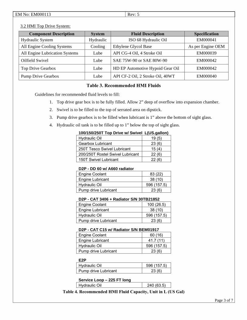
EM No: EM000113 Rev: 5
Page 3 of 7
3.2 HMI Top Drive System:
Component Description System Fluid Description Specification Hydraulic System Hydraulic ISO 68 Hydraulic Oil EM000041
All Engine Cooling Systems Cooling Ethylene Glycol Base As per Engine OEM
All Engine Lubrication Systems Lube API CG-4 Oil, 4 Stroke Oil EM000039
Oilfield Swivel Lube SAE 75W-90 or SAE 80W-90 EM000042
Top Drive Gearbox Lube HD EP Automotive Hypoid Gear Oil EM000042
Pump Drive Gearbox Lube API CF-2 Oil, 2 Stroke Oil, 40WT EM000040
Table 3. Recommended HMI Fluids
Guidelines for recommended fluid levels to fill:
1. Top drive gear box is to be fully filled. Allow 2” deep of overflow into expansion chamber.
2. Swivel is to be filled to the top of serrated area on dipstick.
3. Pump drive gearbox is to be filled when lubricant is 1” above the bottom of sight glass.
4. Hydraulic oil tank is to be filled up to 1” below the top of sight glass.
100/150/250T Top Drive w/ Swivel L(US.gallon)Hydraulic Oil 19 (5) Gearbox Lubricant 23 (6) 250T Tesco Swivel Lubricant 15 (4) 200/250T Rostel Swivel Lubricant 22 (6) 150T Swivel Lubricant 22 (6)
D2P - DD 60 w/ A660 radiator Engine Coolant 83 (22) Engine Lubricant 38 (10) Hydraulic Oil 596 (157.5) Pump drive Lubricant 23 (6)
D2P - CAT 3406 + Radiator S/N 30TB21852 Engine Coolant 100 (26.5) Engine Lubricant 38 (10) Hydraulic Oil 596 (157.5) Pump drive Lubricant 23 (6)
D2P - CAT C15 w/ Radiator S/N BEM01917 Engine Coolant 60 (16) Engine Lubricant 41.7 (11) Hydraulic Oil 596 (157.5) Pump drive Lubricant 23 (6)
E2P Hydraulic Oil 596 (157.5) Pump drive Lubricant 23 (6)
Service Loop – 225 FT long Hydraulic Oil 240 (63.5)
Table 4. Recommended HMI Fluid Capacity, Unit in L (US Gal)

EM No: EM000113 Rev: 5
Page 4 of 7
3.3 ECI Top Drive System:
Component Description System Fluid Description Specification
Hydraulic System Hydraulic ISO 68 Hydraulic Oil (Warm climate) EM000041
ATF Fully Synthetic Transmission Fluid (Cold climate) EM000041
Top Drive Motor Cooling Cooling Antifreeze, Ucartherm, 50/50 EM000048
Oilfield Swivel Lube SAE 75W-90 EM000046
Top Drive Gearbox Lube Oil, Gear, Synthetic SAE 75W-90, Tesco EM000046
Table 5. Recommended ECI Fluids
Guidelines for recommended fluid levels to fill:
1. Top drive gear box is to be filled up to the oil level line on the sight glass.
2. Swivel is to be filled to the top of serrated area on dipstick.
3. Hydraulic oil tank is to be filled up to 1” below the top of sight glass.
4. Motor/Drive coolant tank is to be filled up to 1” below the top of sight glass.
500/650T 900HP Top Drive w/Swivel L(US.gallons) 500/650T 1350HP Top Drive w/ Swivel Hydraulic Oil 31 (8) Hydraulic Oil 31 (8) Gearbox Lubricant 60 (16) Gearbox Lubricant 60 (16) Coolant 3 (0.8) Coolant 4 (1) Swivel Lubricant 80 (21) Swivel Lubricant 80 (21) Mechanical Module 900/1350HP Standard L(US.gallon) 900/1350HP High Ambient L(US.gallon)Hydraulic Oil 208 (55) Hydraulic Oil 208 (55) Coolant 810 (214) Coolant 810 (214) Power Module 900HP L(US.gallon) 1350HP L(US.gallon)Coolant 8 (2) Coolant 10 (2.5) Service Loop – 225 FT long 900HP L(US.gallon) 1350HP L(US.gallon)Hydraulic Oil 47 (12.5) Hydraulic Oil 47 (12.5) Coolant 56 (15) Coolant 91 (24)
Table 6. Recommended ECI Fluid Capacity, Unit in L (US Gal)

EM No: EM000113 Rev: 5
Page 5 of 7
3.4 EXI-600 Top Drive System:
Component Description System Fluid Description Specification
Hydraulic System Hydraulic ISO 68 Hydraulic Oil (Warm climate) EM000041
ATF Fully Synthetic Transmission Fluid (Cold climate) EM000041
Top Drive Gearbox Lube Oil, Gear, Semi-Synthetic SAE 80W-90, Tesco EM000042
Table 7. Recommended EXI-600 Fluids
Guidelines for recommended fluid levels to fill:
1. Top drive gear box is to be filled to ½” of the sight glass.
2. Hydraulic oil tank is to be filled up to 1” below the top of sight glass.
Top Drive L(US.gallon) Hydraulic Oil 20 (5) Gearbox Lubricant 22 (5.8) Hydraulic Power Unit L(US.gallon) Hydraulic Oil 172 (45) Service Loop – 225 ft long L(US.gallon) Hydraulic Oil 47 (12.5)
Table 8. Recommended EXI 600 Fluid Capacity, Unit in L (US Gal)

EM No: EM000113 Rev: 5
Page 6 of 7
3.5 EMI-400 Top Drive System:
Component Description System Fluid Description Specification Hydraulic System Hydraulic ISO 68 Hydraulic Oil (Warm climate) EM000041
ATF Fully Synthetic Transmission Fluid (Cold climate) EM000041
Top Drive Gearbox Lube Oil, Gear, Synthetic SAE 75W-90, Tesco EM000046
Table 9. Recommended EMI 400 Fluids
Guidelines for recommended fluid levels to fill:
1. Top drive gear box is to be filled to cover ¾ of the sight glass.
2. Hydraulic oil tank is to be filled up to 1” below the top of sight glass.
Top Drive L(US.gallon)Hydraulic Oil 20 (5) Gearbox Lubricant 19 (5)
Hydraulic Power Unit L(US.gallon)Hydraulic Oil 172 (45)
Service Loop – 225 FT long L(US.gallon)Hydraulic Oil 47 (12.5)
Table 10. Recommended EMI 400 Fluid Capacity, Unit in L (US Gal)
3.6 HXI Top Drive Systems:
Component Description System Fluid Description Specification
Hydraulic System Hydraulic Open Loop ISO 32 ISO32
Closed Loop ISO 68 ISO68
All Engine Cooling Systems Cooling Ethylene Glycol Base As per Engine OEM
All Engine Lubrication Systems Lube API CG-4-Oil,4 Stroke oil EM000039
Oilfield Swivel Lube SAE 75W-90 or SAE 80W-90 EM000042
Top Drive Gearbox Lube SAE 80W-90 EM000046
Pump Drive Gearbox Lube SAE 80W-90 EM000046
Table 11. Recommended HXI and D4P-700,C-18 Fluids
Guidelines for recommended fluid levels to fill:
1. Standard Gearbox Lubricant is specified in EM000046. Depending on customer requirements, it can be upgraded to ISO 220 Grade.
2. Pump Drive Gearbox to be filled when lubricant is 1” above the bottom of sight glass.
3. Hydraulic oil tank is to be filled up to 1” below the top of sight glass.

EM No: EM000113 Rev: 5
Page 7 of 7
Top Drive L(US.gallon)Hydraulic Oil 20 (5) Gearbox Lubricant 33 (9)
D4P-700 (C18) L(US.gallon)Engine Coolant 50 (13) Engine Lubricant 36 (9.5) Hydraulic Oil 208 (55) Pump Drive 10 (2.5)
D4P-750 (DD 12V2000) L(US.gallon)Engine Coolant 265 (70) Engine Lubricant 70 (18.5) Hydraulic Oil 796 (210) Pump Drive 23 (6)
Service Loop (D4P-700) L(US.gallon)Open Loop Hydraulic Oil 208 (55) Closed Loop Hydraulic Oil 1200 (317)
Service Loop (D4P-750) L(US.gallon)Hydraulic Oil 293 (78)
Table 12. Recommended HXI Fluids, Unit in L (US Gal)
4. Recommendations After a unit starts running, additional fluids are needed to re-fill tanks or pump drive gearboxes to the specified level. This is to make up all fluids pumped and kept in the lines. All values presented in this memo have taken this compensation into consideration.
As mentioned in the Scope section of this memo, amount of engine coolant will vary significantly with engine radiators. And engines from the same manufacturer can come with different radiators. As a result, the values presented for engine coolant used in hydraulic top drive systems are for reference only and are subject to variation.

HI-KALIBRE ACTUATOR MANUAL5187-TDA-SER-C
HI-KALIBRE EQUIPMENT LTD EDMONTON ALBERTA CANADA (780) 435-1111
erasmusp
Text Box
TESCO# 5997

HI-KALIBRE
HI-KALIBRE EQUIPMENT LTD RESERVES ALL CONSENT FROM HI-KALIBRE EQUIPMENT.
EQUIPMENT LTD.
RIGHTS OF DESIGN AND INVENTION
IN THE WHOLE OR IN PART, WITHOUT WRITTEN
THIS DRAWING IS PROPERTY OF HI-KALIBREEQUIPMENT LTD AND MUST BE RETURNED ON DEMAND. THIS PRINT IS LOANED IN CONFIDENCE WITH UNDERSTANDING THATIT IS NOT TO BE REPRODUCED OR DISCLOSED,
9816-45 AVENUEEDMONTON, AB T6E 5C5TEL: (780) 435-1111FAX:(780) 436-5164
12.62OVERALL LENGTHF
9.64ROTATING DEPTHE
12.75NON-ROTATING ØD
DIMENSION: SIZE (in)
A STEM DEPTH 4.80
B STEM HEIGHT 7.81
C ROTATING Ø 12.25
SPECIFICATION: SCALAR (U)MAX HYDRAULIC PRESSURE 2000 PSI
TORQUE @ MAX HYDRAULIC PRESSURE 1220 FT-LB
WEIGHT 250LB
FIGURE 1: 5187 SERIES TOP DRIVE ACTUATOR - OVERALL DIMENSIONS
F
C
A
B
D
E

DOCUMENT NO:
HI-KALIBRE EQUIPMENT LTD. PS-02-001
MAINTENANCE MANUAL REV: DATE:
HI-KALIBRE ROTARY ACTUATOR –
5187-TDA-SER-C OPERATING MANUAL 0 11/01/2008
HEAD OFFICE: 9816 – 45 Avenue, Edmonton, Alberta T6E 5C5 Phone: (780) 435-1111 Fax: (780) 436-5164
http:\\www.hikalibre.com email: [email protected] PAGE 1 OF 8
1. OVERVIEW This document will provide the operating instructions and data for the 5187-TDA-SER-C Rotary Actuator design featuring the new bearing hub configuration. CAUTION: The actuator gets hot while it is running. Stand clear from the actuator while it is rotating. After removing the actuator from service, allow 2 to 3 hours of cool down time before handling or servicing an actuator that was rotating. The actuator should have an open center port control valve installed in the hydraulic lines. This will allow pressure to return to tank after the function cycle is completed. In order to insure full opening/closing of the valve the actuator must be held under pressure for 3-5 seconds before it returns to the neutral position. Once functioned, there should be a delay programmed into the controller so that the top drive does not begin rotating while the hydraulics are being energized. The controller must still allow the actuator to function while rotating in the event of a well control emergency.
2. TECHNICAL SUPPORT For technical support or troubleshooting help, contact your supplier or Hi-Kalibre Equipment Ltd’s 24 hour service line at (780) 435-1111. Before calling for support please make sure to have the actuator serial number ready. It can be found in the large milled ID window located on the OD of the actuator on the lower cylinder. i.e. 5187-TDA-300C
3. SHIPPING AND HANDLING INSTRUCTIONS Actuators that are shipped mounted to the valve should be shipped laying down with the ends of the valve blocked up so no weight is resting on the rotary hub on the actuator. Actuators that are shipped not mounted to a valve body should be shipped in the upright position, making sure that nothing comes into contact with the rotary hub.
4. TROUBLE SHOOTING Refer to Exploded view drawing and Table for corresponding part numbers and diagram. 1. Oil is leaking from the 1/8” NPT vent fittings (22) on the upper cylinder housing (4)
indicates worn seals on the piston racks (8). Refer to section 9 on complete seal kit replacement.

DOCUMENT NO:
HI-KALIBRE EQUIPMENT LTD. PS-02-001
MAINTENANCE MANUAL REV: DATE:
HI-KALIBRE ROTARY ACTUATOR –
5187-TDA-SER-C OPERATING MANUAL 0 11/01/2008
HEAD OFFICE: 9816 – 45 Avenue, Edmonton, Alberta T6E 5C5 Phone: (780) 435-1111 Fax: (780) 436-5164
http:\\www.hikalibre.com email: [email protected] PAGE 2 OF 8
2. Oil is leaking from between the sleeve (13) and the rotary hub (14), or between the sleeve (13) and lower end cap (15) indicates that the hub seal set (26) is worn and needs to be replaced. Refer to section 7 on rotary hub seal set replacement.
3. Actuator/Valve fails to rotate when functioning the hydraulics, check the following: a) The hex drives are installed correctly. b) The main window of the valve is aligned on the same side as the main window on
the actuator. c) Both the valve and actuator are in the open position when the hex drives are
installed. d) The hydraulic lines are connected properly.
If none of these correct the problem then check the timing of the racks to the pinion inside the actuator. All mounted units are tested for operation before shipping, check timing of the unit if it has been field serviced. Refer to section 9 for proper timing of the racks and pinion. 4. Never plug any holes with leaking vent fittings as this could cause a pressure buildup
and severe personal injury to yourself or co-workers. 5. Actuator is extremely hot (more than 37°C / 100° F over ambient temperature). Insure
that there is no residual back pressure on the actuator lines that could be energizing the seals as the unit is rotating.
5. STRIPPING THE ACTUATOR 1. Make sure that the actuator and valve are in the open position. Remove the hydraulic
lines after making sure that there is no pressure in the lines. Failure to do so could result in serious injury.
2. Remove both the internal snap rings (9) from inside the pinions (11). There is a pair of snap ring pliers included in the actuator strip kit (P/N: HK-TDA-STRIPKIT).
3. Pull both of the hex drive shafts (10) from inside of the hex in each pinion. To make this easier, there is a slide hammer included with the strip kit as well.
4. Remove both the upper and lower worm ring clamps (23) from the cylinder housings. They are used to cover the eight lock pin retaining screws.
5. Remove two of the upper set of lock pin retaining assemblies, 180° apart from each other. The lock pin assemblies include a 1” set screw (5), a coil spring (6), and a lock pin (7).
6. Install the two lifting handles into the two empty holes. The lifting handles are included in the HK-TDA-STRIPKIT. Secure a lifting apparatus onto the lifting handles as the actuator is heavy (250 lbs).
7. Loosen the six remaining lock pin assemblies. Back off each assembly roughly 10 to 12 full turns until they come out.
8. Lift the actuator off the valve body.

DOCUMENT NO:
HI-KALIBRE EQUIPMENT LTD. PS-02-001
MAINTENANCE MANUAL REV: DATE:
HI-KALIBRE ROTARY ACTUATOR –
5187-TDA-SER-C OPERATING MANUAL 0 11/01/2008
HEAD OFFICE: 9816 – 45 Avenue, Edmonton, Alberta T6E 5C5 Phone: (780) 435-1111 Fax: (780) 436-5164
http:\\www.hikalibre.com email: [email protected] PAGE 3 OF 8
6. RE-INSTALLING THE ACTUATOR 1. Orient the valve and actuator for installation. Double check to make sure that the valve
and actuator are both in the OPEN position. 2. Slide the actuator onto the valve body. Align the main stamping window of the actuator
with the main stamping window of the valve body. Rotate the actuator 45° to the right and lower it until the actuator passes the first stem hole.
3. Insert the lower lock pin assemblies. They consist of a lock pin (7), coil spring (6), and a 1” set screw (5).
4. Pre-load the lock pin assemblies. Place a slight load on the coil springs by hand tightening the set screws of each assembly.
5. Lower the actuator to the locator groove on the valve body. The pre-loaded lock pin assemblies will pick up the locator groove on the body. Rotate the actuator 45° left to engage the lock pins into the valve detents.
6. Shim the actuator with brass shim stock found in the HK-TDA-STRIPKIT. Insert a total of eight pieces, four at the top and four at the bottom spaced equally apart.
7. Torque the four lower lock pin assemblies to 100 ft-lbs. 8. Remove the two lifting handles and install the four upper lock pin assemblies. Torque
those four to 100 ft-lbs as well. ***After the first 12 hours of drilling, make sure the re-torque all eight lock pins to 100 ft-lbs.
9. Periodically check the lock pins as part of the routine maintenance checks on the rig. 10. Remove the brass shim stock and place it back in the HK-TDA-STRIPKIT. 11. Install the hex drives (10) into the pinions (11) and secure them with the internal snap
rings (9). 12. Install the upper and lower worm ring clamps (23) and you are finished.
7. ROTARY HUB SEAL SET REPLACEMENT The rotary hub seals should be replaced after the actuator has been stripped off the valve body. The work area should be clean so as to avoid contaminating the seals or sealing surfaces. 1. Function the actuator to the OPEN position. Disconnect the hydraulic lines, making sure
the release any pressure before disconnecting them so you avoid potential injury. Remove the eight locking pins (7) from the actuator and take the actuator off the valve body. Take the actuator to a clean work area, carefully as the actuator weighs up to 250 lbs.
2. Flip the rotary actuator so that the lower end cap (15) faces up. 3. Remove the 5/16” x 3-3/4” NF socket head cap screws (16) from the lower end cap (15). 4. Take out the two 5/16” orbital plugs (25) located on the end cap.
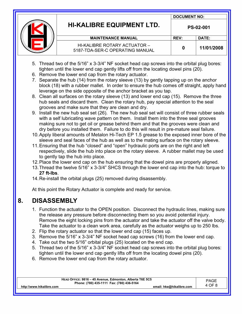
DOCUMENT NO:
HI-KALIBRE EQUIPMENT LTD. PS-02-001
MAINTENANCE MANUAL REV: DATE:
HI-KALIBRE ROTARY ACTUATOR –
5187-TDA-SER-C OPERATING MANUAL 0 11/01/2008
HEAD OFFICE: 9816 – 45 Avenue, Edmonton, Alberta T6E 5C5 Phone: (780) 435-1111 Fax: (780) 436-5164
http:\\www.hikalibre.com email: [email protected] PAGE 4 OF 8
5. Thread two of the 5/16” x 3-3/4” NF socket head cap screws into the orbital plug bores: tighten until the lower end cap gently lifts off from the locating dowel pins (20).
6. Remove the lower end cap from the rotary actuator. 7. Separate the hub (14) from the rotary sleeve (13) by gently tapping up on the anchor
block (18) with a rubber mallet. In order to ensure the hub comes off straight, apply hand leverage on the side opposite of the anchor bracket as you tap.
8. Clean all surfaces on the rotary sleeve (13) and lower end cap (15). Remove the three hub seals and discard them. Clean the rotary hub, pay special attention to the seal grooves and make sure that they are clean and dry.
9. Install the new hub seal set (26). The new hub seal set will consist of three rubber seals with a self lubricating wave pattern on them. Install them into the three seal grooves making sure not to get oil or grease behind them and that the grooves were clean and dry before you installed them. Failure to do this will result in pre-mature seal failure.
10. Apply liberal amounts of Metalon Hi-Tech EP 1.5 grease to the exposed inner bore of the sleeve and seal faces of the hub as well as to the mating surface on the rotary sleeve.
11. Ensuring that the hub “closed” and “open” hydraulic ports are on the right and left respectively, slide the hub into place on the rotary sleeve. A rubber mallet may be used to gently tap the hub into place.
12. Place the lower end cap on the hub ensuring that the dowel pins are properly aligned. 13. Thread the twelve 5/16” x 3-3/4” SHCS through the lower end cap into the hub: torque to
27 ft-lbs. 14. Re-install the orbital plugs (25) removed during disassembly. At this point the Rotary Actuator is complete and ready for service.
8. DISASSEMBLY 1. Function the actuator to the OPEN position. Disconnect the hydraulic lines, making sure
the release any pressure before disconnecting them so you avoid potential injury. Remove the eight locking pins from the actuator and take the actuator off the valve body. Take the actuator to a clean work area, carefully as the actuator weighs up to 250 lbs.
2. Flip the rotary actuator so that the lower end cap (15) faces up. 3. Remove the 5/16” x 3-3/4” NF socket head cap screws (16) from the lower end cap. 4. Take out the two 5/16” orbital plugs (25) located on the end cap. 5. Thread two of the 5/16” x 3-3/4” NF socket head cap screws into the orbital plug bores:
tighten until the lower end cap gently lifts off from the locating dowel pins (20). 6. Remove the lower end cap from the rotary actuator.

DOCUMENT NO:
HI-KALIBRE EQUIPMENT LTD. PS-02-001
MAINTENANCE MANUAL REV: DATE:
HI-KALIBRE ROTARY ACTUATOR –
5187-TDA-SER-C OPERATING MANUAL 0 11/01/2008
HEAD OFFICE: 9816 – 45 Avenue, Edmonton, Alberta T6E 5C5 Phone: (780) 435-1111 Fax: (780) 436-5164
http:\\www.hikalibre.com email: [email protected] PAGE 5 OF 8
7. Separate the hub (14) from the rotary sleeve (13) by gently tapping up on the anchor block (18) with a rubber mallet. In order to ensure the hub comes off straight, apply hand leverage on the side opposite of the anchor bracket as you tap.
8. Remove both threaded bushings (19) from the rotary hub (14) and inspect them for wear. Discard the o-rings from the threaded bushings.
9. Remove the five bearing housings (29) from the hub by taking out the two ¼” bolts (35) from each housing.
10. Be careful when removing the pins (30), bearings (31), and springs (33). Take them out slowly and carefully so as to not injure anyone. Inspect the bearings, pins, and springs for wear. Replace parts as required.
11. Remove the rotary sleeve (13) from the lower cylinder housing (12) by taking out the eighteen socket head cap screws. Inspect the sleeve for damage and discard all the seals.
12. Flip the actuator over so that you can remove the upper end cap (2). Remove all eighteen 5/16” x ¾” NF socket head cap screws (1) from the upper end cap (2).
13. Take out the two 5/16” orbital plugs (25) located on the end cap using the Allen wrench supplied in your HK-TDA-STRIPKIT.
14. Thread two of the 5/16” x 3/4” NF socket head cap screws into the orbital plug bores: tighten until the upper end cap gently lifts off from the locating dowel pins (17). Inspect the upper end cap and discard the seals.
15. To separate the two cylinder halves (4 & 12), begin by taking out the eight ½” x 4-1/2” NF socket head cap screws (3).
16. Pull the upper cylinder directly up. Take out the two ½” dowel pins (17) and discard the o-rings.
17. Remove the racks (8) and pinions (11) from each side of the actuator. Take off the plastic pinion riders (37), the Teflon face seals (38), and the o-rings from the racks and discard them.
18. Inspect and thoroughly clean all the hard parts from the actuator. Make sure to make a record of the parts that you will need to order for replacement along with the seal kits/seal sets.
9. ASSEMBLY 1. Make sure that all the parts have been thoroughly cleaned and are free from
contamination. If the actuator is contaminated during assembly it can lead to pre-mature failure in the field.
2. Install all of the o-rings, back-ups, and other seals onto all the required parts being careful not to twist them on.

DOCUMENT NO:
HI-KALIBRE EQUIPMENT LTD. PS-02-001
MAINTENANCE MANUAL REV: DATE:
HI-KALIBRE ROTARY ACTUATOR –
5187-TDA-SER-C OPERATING MANUAL 0 11/01/2008
HEAD OFFICE: 9816 – 45 Avenue, Edmonton, Alberta T6E 5C5 Phone: (780) 435-1111 Fax: (780) 436-5164
http:\\www.hikalibre.com email: [email protected] PAGE 6 OF 8
3. Prepare the racks (8) and pinions (11) for assembly. Make sure that there are two o-rings and four back ups on each rack. Apply a light coat of grease to the racks. Press one Teflon pinion seal (38) into both faces on each pinion. Apply another light coating of grease to the pinion teeth and inside the pinion riders (37). DO NOT grease the outside surfaces of the pinion riders. Slide the pinion riders onto the pinions; it is the same procedure for both pinions.
4. Refer to Figure 2 for proper timing of the racks and pinions. To maintain proper timing of the racks and pinions so that the actuator will function properly, start by orienting the main window on the lower cylinder housing (12) as shown in Figure 2.
5. With the pinion indicators (small milled grooves from hex) facing out and in the upright position, place the pinion (11) and two racks (8) into the pinion cavity so that the rack closest to the window (front) is in the higher position, and the farthest rack (back) is in the lower position. Do the same thing for both cavities on the actuator.
6. When the racks and pinions are installed and timed properly, the racks should bottom out when the pinion indicators are pointing directly up as shown in Figure 2, if not then go back and start over so you prevent the actuator from malfunctioning and damaging the valve.
7. Install the two ½” dowel pins (17) and all the o-rings into the lower cylinder (12). Line the upper cylinder (4) and lower cylinder up and mate them together. Tighten the eight ½” NF x 4-1/2” long socket head cap screws (3) to 100 ft-lbs.
8. Install the ½” dowel pins (17) and o-rings in the upper end cap (2). Align the dowel pins with the holes in the upper cylinder and fasten it down with eighteen of the 5/16 NF x ¾” long socket head cap screws (1). Torque them to 27 ft-lbs to make sure they stay tight.
9. Flip the actuator over and prepare to install the rotary sleeve (13). Install the two ½” dowel pins (17) and the o-rings into the sleeve. Attach it to the lower cylinder (12) by lining up the dowel pins and tightening it down with eighteen of the 5/16” NF x ¾” long socket head cap screws (1). Torque them to 27-ft-lbs as well.
10. Install the five bearing assemblies into the rotary hub. Begin by installing the spring (33), bearing shims (32), and bearings (31). A spring compression tool (HK-4186-23) can be purchased (it also comes in an actuator service kit (ASK) or the rotary bearing hub major repair kit (HK-ROTOHUB-MRK)). Install a pin in each hole, place the spring in between making sure the flats on the pins are lined up. Compress the spring slightly so the pins will go into the two holes. Remove the tool, add the bearings (31) and shims (32). Once they are in, place the bearing housing (30) over top, install the bolt retainer strips (34), and the two ¼” bolts (35). Torque the bolts to 6 ft-lbs. Bend the ends of the retainer strips up against the bolt heads so the bolts do not work loose. Repeat this step for all five bearing housings on the rotary hub refer to FIGURE 3.
11. Install the new hub seal set (26). The new hub seal set will consist of three rubber seals with a self lubricating wave pattern on them. Install them into the three seal grooves
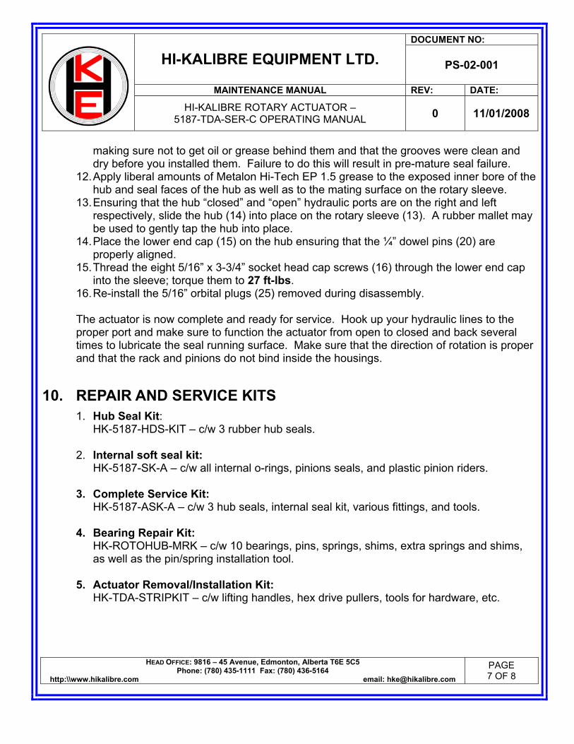
DOCUMENT NO:
HI-KALIBRE EQUIPMENT LTD. PS-02-001
MAINTENANCE MANUAL REV: DATE:
HI-KALIBRE ROTARY ACTUATOR –
5187-TDA-SER-C OPERATING MANUAL 0 11/01/2008
HEAD OFFICE: 9816 – 45 Avenue, Edmonton, Alberta T6E 5C5 Phone: (780) 435-1111 Fax: (780) 436-5164
http:\\www.hikalibre.com email: [email protected] PAGE 7 OF 8
making sure not to get oil or grease behind them and that the grooves were clean and dry before you installed them. Failure to do this will result in pre-mature seal failure.
12. Apply liberal amounts of Metalon Hi-Tech EP 1.5 grease to the exposed inner bore of the hub and seal faces of the hub as well as to the mating surface on the rotary sleeve.
13. Ensuring that the hub “closed” and “open” hydraulic ports are on the right and left respectively, slide the hub (14) into place on the rotary sleeve (13). A rubber mallet may be used to gently tap the hub into place.
14. Place the lower end cap (15) on the hub ensuring that the ¼” dowel pins (20) are properly aligned.
15. Thread the eight 5/16” x 3-3/4” socket head cap screws (16) through the lower end cap into the sleeve; torque them to 27 ft-lbs.
16. Re-install the 5/16” orbital plugs (25) removed during disassembly.
The actuator is now complete and ready for service. Hook up your hydraulic lines to the proper port and make sure to function the actuator from open to closed and back several times to lubricate the seal running surface. Make sure that the direction of rotation is proper and that the rack and pinions do not bind inside the housings.
10. REPAIR AND SERVICE KITS 1. Hub Seal Kit:
HK-5187-HDS-KIT – c/w 3 rubber hub seals.
2. Internal soft seal kit: HK-5187-SK-A – c/w all internal o-rings, pinions seals, and plastic pinion riders.
3. Complete Service Kit: HK-5187-ASK-A – c/w 3 hub seals, internal seal kit, various fittings, and tools.
4. Bearing Repair Kit: HK-ROTOHUB-MRK – c/w 10 bearings, pins, springs, shims, extra springs and shims, as well as the pin/spring installation tool.
5. Actuator Removal/Installation Kit: HK-TDA-STRIPKIT – c/w lifting handles, hex drive pullers, tools for hardware, etc.
erasmusp
Typewritten Text
Tesco# 8256
erasmusp
Typewritten Text
erasmusp
Typewritten Text
Tesco# 970236
erasmusp
Typewritten Text
Tesco# 970301
erasmusp
Typewritten Text
Tesco# 970302
erasmusp
Typewritten Text
Tesco# 970303

38
TS
18
36
20
21
22
13
31
24 19
34
26
30
27
25
28
29
32
35
37
33
4
36
BB
36
TH
36
5187-TDA-SER-C
36
250 LB
36
1500 PSI
HK-5187-ASK-A
1
2
3
17
5
6
7
8
910
11
12
14
15
16
23
36
SEE FIGURE 3FOR BEARINGARRANGEMENT
10/30/08
ITEM # PART # DESCRIPTION QTY
1 5/16NFX3/4-SHCS SOCKET HEAD CAP SCREW 36
2 HK-5187-1A UPPER END CAP 1
3 1/2NFX4-1/2 SHCS SOCKET HEAD CAP SCREW 8
4 HK-5187-2A UPPER CYLINDER 1
5 1NSX1-SETSCREW SETSCREW 8
7 HK-4186-9 LOCKPIN 8
8 HK-4186-8 PISTON RACK 4
9 N1300-0087-AS INTERNAL SNAP RING 2
10 HK-5186-11A HEX DRIVE SHAFT 2
11 HK-4187-7 PINION 2
12 HK-5187-3B LOWER CYLINDER 1
13 HK-5187-4A ROTO SLEEVE 1
14 HK-5186-5A HUB 1
15 HK-5187-6A LOWER END CAP 1
17 1/2X3/4-DOWEL DOWEL PIN 6
18 HK-4186-12 ANCHOR BLOCK 1
19 HK-4186-13 THREADED BUSHING 2
20 HK-4186-14 DOWEL PIN 2
21 5/16X1-3/4-SHCS SOCKET HEAD CAP SCREW 6
22 323060 REL. FITTING 15-25 2
23 HAS-96 WORM CLAMP 4
24 O5CP-6 PLUG 2
25 20-ORB-127-PHH ORB PLUG 4
26 HK-5187-HDS-KIT HYDRO HUB SEAL KIT 1
27 HK-308692 CAUTION:MAY BE HOT DECAL 1
28 HK-308693-A TORQUE LOCKPINS/FUNCTION HYDRAULICS DECAL 1
29 HK-4186-20 BEARING HOUSING 5
31 6001-2RS1 ROLLER BEARING 10
32 656-163 SHIM 10
33 8000-SPRING COIL SPRING 5
34 HK-4186-22 LOCK STRAP 5
36 HK-5187-SK-A SEAL KIT 1
37 HK-4186-10-DEV PINION RIDER 4
38 HK-4186-16 PINION SEAL 4
EQUIPMENT LTD.HI-KALIBRE
PATENTS APPLY
NOTES:
APPROVED BY
CHECKED BY
DRAWN BY
DATE
WEIGHT
MAJOR REPAIR KITMADE IN CANADA
EDMONTON, ALBERTA, CANADA
WORKING PRESSURE
PHONE 780-435-1111FAX 780-436-51649816-45 AVENUE
ASSEMBLY NUMBER
erasmusp
Typewritten Text
1205
erasmusp
Typewritten Text
1203
erasmusp
Typewritten Text
1207
erasmusp
Typewritten Text
1206
erasmusp
Typewritten Text
8420
erasmusp
Typewritten Text
1209
erasmusp
Typewritten Text
720738
erasmusp
Typewritten Text
1204
erasmusp
Typewritten Text
8415
erasmusp
Typewritten Text
8417
erasmusp
Typewritten Text
4475
erasmusp
Typewritten Text
9732
erasmusp
Typewritten Text
4353
erasmusp
Typewritten Text
1196
erasmusp
Typewritten Text
7206
erasmusp
Typewritten Text
970236
erasmusp
Typewritten Text
5132
erasmusp
Typewritten Text
970301
erasmusp
Typewritten Text
TESCO#
moormank
Rectangle
erasmusp
Typewritten Text
970302
erasmusp
Typewritten Text
970329
erasmusp
Typewritten Text
970330
erasmusp
Typewritten Text
5002006
erasmusp
Typewritten Text
5002000
erasmusp
Typewritten Text
5002005
erasmusp
Typewritten Text
5002004
erasmusp
Typewritten Text
5002003
erasmusp
Typewritten Text
5002002

LEFT SIDE VIEW
FIGURE 2: 5187 SERIES TOP DRIVE ACTUATOR - RACK TIMING
EQUIPMENT LTD.
CONSENT FROM HI-KALIBRE EQUIPMENT. HI-KALIBRE EQUIPMENT LTD RESERVES ALL RIGHTS OF DESIGN AND INVENTION
IN THE WHOLE OR IN PART, WITHOUT WRITTEN
HI-KALIBRETHIS DRAWING IS PROPERTY OF HI-KALIBREEQUIPMENT LTD AND MUST BE RETURNED ON DEMAND. THIS PRINT IS LOANED IN CONFIDENCE WITH UNDERSTANDING THATIT IS NOT TO BE REPRODUCED OR DISCLOSED,
9816-45 AVENUEEDMONTON, AB T6E 5C5TEL: (780) 435-1111FAX:(780) 436-5164
RIGHT SIDE VIEW
LEFT SIDE
RIGHT SIDE

FIGURE 3: 4186 SERIES TOP DRIVE ACTUATOR - HUB BEARING ARRANGEMENT
HI-KALIBRE
HI-KALIBRE EQUIPMENT LTD RESERVES ALL CONSENT FROM HI-KALIBRE EQUIPMENT.
EQUIPMENT LTD.
RIGHTS OF DESIGN AND INVENTION
IN THE WHOLE OR IN PART, WITHOUT WRITTEN
THIS DRAWING IS PROPERTY OF HI-KALIBREEQUIPMENT LTD AND MUST BE RETURNED ON DEMAND. THIS PRINT IS LOANED IN CONFIDENCE WITH UNDERSTANDING THATIT IS NOT TO BE REPRODUCED OR DISCLOSED,
9816-45 AVENUEEDMONTON, AB T6E 5C5TEL: (780) 435-1111FAX:(780) 436-5164
1728
2918
19
35
30

DOCUMENT NO:
HI-KALIBRE EQUIPMENT LTD. PS-02-001
MAINTENANCE MANUAL REV: DATE:
HI-KALIBRE ROTARY ACTUATOR –
5187-TDA-SER-C OPERATING MANUAL 0 11/01/2008
HEAD OFFICE: 9816 – 45 Avenue, Edmonton, Alberta T6E 5C5 Phone: (780) 435-1111 Fax: (780) 436-5164
http:\\www.hikalibre.com email: [email protected] PAGE 8 OF 8
REV: DATE: DESCRIPTION: PREP: REVIEW: APPR:
0 11/07/2008 INITIAL APPROVAL BB PR TH

HI-KALIBRE ACTUATOR MANUAL5187-TDA-SER-C
HI-KALIBRE EQUIPMENT LTD EDMONTON ALBERTA CANADA (780) 435-1111
erasmusp
Text Box
TESCO# 5997

HI-KALIBRE
HI-KALIBRE EQUIPMENT LTD RESERVES ALL CONSENT FROM HI-KALIBRE EQUIPMENT.
EQUIPMENT LTD.
RIGHTS OF DESIGN AND INVENTION
IN THE WHOLE OR IN PART, WITHOUT WRITTEN
THIS DRAWING IS PROPERTY OF HI-KALIBREEQUIPMENT LTD AND MUST BE RETURNED ON DEMAND. THIS PRINT IS LOANED IN CONFIDENCE WITH UNDERSTANDING THATIT IS NOT TO BE REPRODUCED OR DISCLOSED,
9816-45 AVENUEEDMONTON, AB T6E 5C5TEL: (780) 435-1111FAX:(780) 436-5164
12.62OVERALL LENGTHF
9.64ROTATING DEPTHE
12.75NON-ROTATING ØD
DIMENSION: SIZE (in)
A STEM DEPTH 4.80
B STEM HEIGHT 7.81
C ROTATING Ø 12.25
SPECIFICATION: SCALAR (U)MAX HYDRAULIC PRESSURE 2000 PSI
TORQUE @ MAX HYDRAULIC PRESSURE 1220 FT-LB
WEIGHT 250LB
FIGURE 1: 5187 SERIES TOP DRIVE ACTUATOR - OVERALL DIMENSIONS
F
C
A
B
D
E

DOCUMENT NO:
HI-KALIBRE EQUIPMENT LTD. PS-02-001
MAINTENANCE MANUAL REV: DATE:
HI-KALIBRE ROTARY ACTUATOR –
5187-TDA-SER-C OPERATING MANUAL 0 11/01/2008
HEAD OFFICE: 9816 – 45 Avenue, Edmonton, Alberta T6E 5C5 Phone: (780) 435-1111 Fax: (780) 436-5164
http:\\www.hikalibre.com email: [email protected] PAGE 1 OF 8
1. OVERVIEW This document will provide the operating instructions and data for the 5187-TDA-SER-C Rotary Actuator design featuring the new bearing hub configuration. CAUTION: The actuator gets hot while it is running. Stand clear from the actuator while it is rotating. After removing the actuator from service, allow 2 to 3 hours of cool down time before handling or servicing an actuator that was rotating. The actuator should have an open center port control valve installed in the hydraulic lines. This will allow pressure to return to tank after the function cycle is completed. In order to insure full opening/closing of the valve the actuator must be held under pressure for 3-5 seconds before it returns to the neutral position. Once functioned, there should be a delay programmed into the controller so that the top drive does not begin rotating while the hydraulics are being energized. The controller must still allow the actuator to function while rotating in the event of a well control emergency.
2. TECHNICAL SUPPORT For technical support or troubleshooting help, contact your supplier or Hi-Kalibre Equipment Ltd’s 24 hour service line at (780) 435-1111. Before calling for support please make sure to have the actuator serial number ready. It can be found in the large milled ID window located on the OD of the actuator on the lower cylinder. i.e. 5187-TDA-300C
3. SHIPPING AND HANDLING INSTRUCTIONS Actuators that are shipped mounted to the valve should be shipped laying down with the ends of the valve blocked up so no weight is resting on the rotary hub on the actuator. Actuators that are shipped not mounted to a valve body should be shipped in the upright position, making sure that nothing comes into contact with the rotary hub.
4. TROUBLE SHOOTING Refer to Exploded view drawing and Table for corresponding part numbers and diagram. 1. Oil is leaking from the 1/8” NPT vent fittings (22) on the upper cylinder housing (4)
indicates worn seals on the piston racks (8). Refer to section 9 on complete seal kit replacement.

DOCUMENT NO:
HI-KALIBRE EQUIPMENT LTD. PS-02-001
MAINTENANCE MANUAL REV: DATE:
HI-KALIBRE ROTARY ACTUATOR –
5187-TDA-SER-C OPERATING MANUAL 0 11/01/2008
HEAD OFFICE: 9816 – 45 Avenue, Edmonton, Alberta T6E 5C5 Phone: (780) 435-1111 Fax: (780) 436-5164
http:\\www.hikalibre.com email: [email protected] PAGE 2 OF 8
2. Oil is leaking from between the sleeve (13) and the rotary hub (14), or between the sleeve (13) and lower end cap (15) indicates that the hub seal set (26) is worn and needs to be replaced. Refer to section 7 on rotary hub seal set replacement.
3. Actuator/Valve fails to rotate when functioning the hydraulics, check the following: a) The hex drives are installed correctly. b) The main window of the valve is aligned on the same side as the main window on
the actuator. c) Both the valve and actuator are in the open position when the hex drives are
installed. d) The hydraulic lines are connected properly.
If none of these correct the problem then check the timing of the racks to the pinion inside the actuator. All mounted units are tested for operation before shipping, check timing of the unit if it has been field serviced. Refer to section 9 for proper timing of the racks and pinion. 4. Never plug any holes with leaking vent fittings as this could cause a pressure buildup
and severe personal injury to yourself or co-workers. 5. Actuator is extremely hot (more than 37°C / 100° F over ambient temperature). Insure
that there is no residual back pressure on the actuator lines that could be energizing the seals as the unit is rotating.
5. STRIPPING THE ACTUATOR 1. Make sure that the actuator and valve are in the open position. Remove the hydraulic
lines after making sure that there is no pressure in the lines. Failure to do so could result in serious injury.
2. Remove both the internal snap rings (9) from inside the pinions (11). There is a pair of snap ring pliers included in the actuator strip kit (P/N: HK-TDA-STRIPKIT).
3. Pull both of the hex drive shafts (10) from inside of the hex in each pinion. To make this easier, there is a slide hammer included with the strip kit as well.
4. Remove both the upper and lower worm ring clamps (23) from the cylinder housings. They are used to cover the eight lock pin retaining screws.
5. Remove two of the upper set of lock pin retaining assemblies, 180° apart from each other. The lock pin assemblies include a 1” set screw (5), a coil spring (6), and a lock pin (7).
6. Install the two lifting handles into the two empty holes. The lifting handles are included in the HK-TDA-STRIPKIT. Secure a lifting apparatus onto the lifting handles as the actuator is heavy (250 lbs).
7. Loosen the six remaining lock pin assemblies. Back off each assembly roughly 10 to 12 full turns until they come out.
8. Lift the actuator off the valve body.

DOCUMENT NO:
HI-KALIBRE EQUIPMENT LTD. PS-02-001
MAINTENANCE MANUAL REV: DATE:
HI-KALIBRE ROTARY ACTUATOR –
5187-TDA-SER-C OPERATING MANUAL 0 11/01/2008
HEAD OFFICE: 9816 – 45 Avenue, Edmonton, Alberta T6E 5C5 Phone: (780) 435-1111 Fax: (780) 436-5164
http:\\www.hikalibre.com email: [email protected] PAGE 3 OF 8
6. RE-INSTALLING THE ACTUATOR 1. Orient the valve and actuator for installation. Double check to make sure that the valve
and actuator are both in the OPEN position. 2. Slide the actuator onto the valve body. Align the main stamping window of the actuator
with the main stamping window of the valve body. Rotate the actuator 45° to the right and lower it until the actuator passes the first stem hole.
3. Insert the lower lock pin assemblies. They consist of a lock pin (7), coil spring (6), and a 1” set screw (5).
4. Pre-load the lock pin assemblies. Place a slight load on the coil springs by hand tightening the set screws of each assembly.
5. Lower the actuator to the locator groove on the valve body. The pre-loaded lock pin assemblies will pick up the locator groove on the body. Rotate the actuator 45° left to engage the lock pins into the valve detents.
6. Shim the actuator with brass shim stock found in the HK-TDA-STRIPKIT. Insert a total of eight pieces, four at the top and four at the bottom spaced equally apart.
7. Torque the four lower lock pin assemblies to 100 ft-lbs. 8. Remove the two lifting handles and install the four upper lock pin assemblies. Torque
those four to 100 ft-lbs as well. ***After the first 12 hours of drilling, make sure the re-torque all eight lock pins to 100 ft-lbs.
9. Periodically check the lock pins as part of the routine maintenance checks on the rig. 10. Remove the brass shim stock and place it back in the HK-TDA-STRIPKIT. 11. Install the hex drives (10) into the pinions (11) and secure them with the internal snap
rings (9). 12. Install the upper and lower worm ring clamps (23) and you are finished.
7. ROTARY HUB SEAL SET REPLACEMENT The rotary hub seals should be replaced after the actuator has been stripped off the valve body. The work area should be clean so as to avoid contaminating the seals or sealing surfaces. 1. Function the actuator to the OPEN position. Disconnect the hydraulic lines, making sure
the release any pressure before disconnecting them so you avoid potential injury. Remove the eight locking pins (7) from the actuator and take the actuator off the valve body. Take the actuator to a clean work area, carefully as the actuator weighs up to 250 lbs.
2. Flip the rotary actuator so that the lower end cap (15) faces up. 3. Remove the 5/16” x 3-3/4” NF socket head cap screws (16) from the lower end cap (15). 4. Take out the two 5/16” orbital plugs (25) located on the end cap.

DOCUMENT NO:
HI-KALIBRE EQUIPMENT LTD. PS-02-001
MAINTENANCE MANUAL REV: DATE:
HI-KALIBRE ROTARY ACTUATOR –
5187-TDA-SER-C OPERATING MANUAL 0 11/01/2008
HEAD OFFICE: 9816 – 45 Avenue, Edmonton, Alberta T6E 5C5 Phone: (780) 435-1111 Fax: (780) 436-5164
http:\\www.hikalibre.com email: [email protected] PAGE 4 OF 8
5. Thread two of the 5/16” x 3-3/4” NF socket head cap screws into the orbital plug bores: tighten until the lower end cap gently lifts off from the locating dowel pins (20).
6. Remove the lower end cap from the rotary actuator. 7. Separate the hub (14) from the rotary sleeve (13) by gently tapping up on the anchor
block (18) with a rubber mallet. In order to ensure the hub comes off straight, apply hand leverage on the side opposite of the anchor bracket as you tap.
8. Clean all surfaces on the rotary sleeve (13) and lower end cap (15). Remove the three hub seals and discard them. Clean the rotary hub, pay special attention to the seal grooves and make sure that they are clean and dry.
9. Install the new hub seal set (26). The new hub seal set will consist of three rubber seals with a self lubricating wave pattern on them. Install them into the three seal grooves making sure not to get oil or grease behind them and that the grooves were clean and dry before you installed them. Failure to do this will result in pre-mature seal failure.
10. Apply liberal amounts of Metalon Hi-Tech EP 1.5 grease to the exposed inner bore of the sleeve and seal faces of the hub as well as to the mating surface on the rotary sleeve.
11. Ensuring that the hub “closed” and “open” hydraulic ports are on the right and left respectively, slide the hub into place on the rotary sleeve. A rubber mallet may be used to gently tap the hub into place.
12. Place the lower end cap on the hub ensuring that the dowel pins are properly aligned. 13. Thread the twelve 5/16” x 3-3/4” SHCS through the lower end cap into the hub: torque to
27 ft-lbs. 14. Re-install the orbital plugs (25) removed during disassembly. At this point the Rotary Actuator is complete and ready for service.
8. DISASSEMBLY 1. Function the actuator to the OPEN position. Disconnect the hydraulic lines, making sure
the release any pressure before disconnecting them so you avoid potential injury. Remove the eight locking pins from the actuator and take the actuator off the valve body. Take the actuator to a clean work area, carefully as the actuator weighs up to 250 lbs.
2. Flip the rotary actuator so that the lower end cap (15) faces up. 3. Remove the 5/16” x 3-3/4” NF socket head cap screws (16) from the lower end cap. 4. Take out the two 5/16” orbital plugs (25) located on the end cap. 5. Thread two of the 5/16” x 3-3/4” NF socket head cap screws into the orbital plug bores:
tighten until the lower end cap gently lifts off from the locating dowel pins (20). 6. Remove the lower end cap from the rotary actuator.
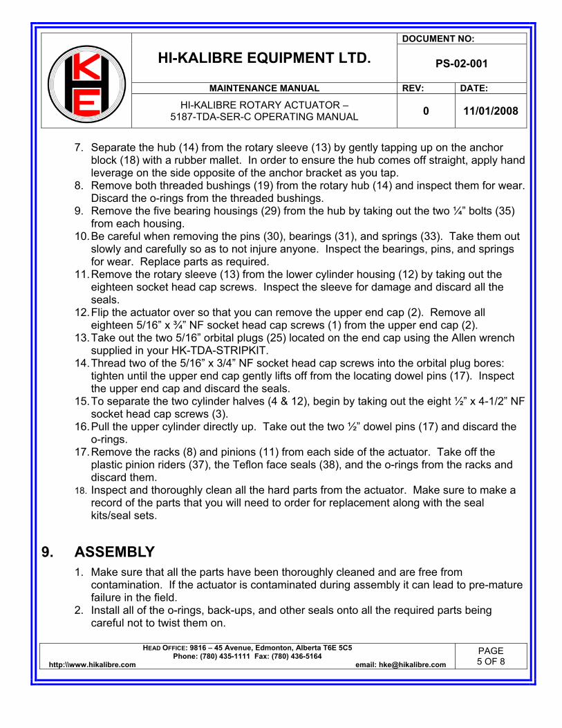
DOCUMENT NO:
HI-KALIBRE EQUIPMENT LTD. PS-02-001
MAINTENANCE MANUAL REV: DATE:
HI-KALIBRE ROTARY ACTUATOR –
5187-TDA-SER-C OPERATING MANUAL 0 11/01/2008
HEAD OFFICE: 9816 – 45 Avenue, Edmonton, Alberta T6E 5C5 Phone: (780) 435-1111 Fax: (780) 436-5164
http:\\www.hikalibre.com email: [email protected] PAGE 5 OF 8
7. Separate the hub (14) from the rotary sleeve (13) by gently tapping up on the anchor block (18) with a rubber mallet. In order to ensure the hub comes off straight, apply hand leverage on the side opposite of the anchor bracket as you tap.
8. Remove both threaded bushings (19) from the rotary hub (14) and inspect them for wear. Discard the o-rings from the threaded bushings.
9. Remove the five bearing housings (29) from the hub by taking out the two ¼” bolts (35) from each housing.
10. Be careful when removing the pins (30), bearings (31), and springs (33). Take them out slowly and carefully so as to not injure anyone. Inspect the bearings, pins, and springs for wear. Replace parts as required.
11. Remove the rotary sleeve (13) from the lower cylinder housing (12) by taking out the eighteen socket head cap screws. Inspect the sleeve for damage and discard all the seals.
12. Flip the actuator over so that you can remove the upper end cap (2). Remove all eighteen 5/16” x ¾” NF socket head cap screws (1) from the upper end cap (2).
13. Take out the two 5/16” orbital plugs (25) located on the end cap using the Allen wrench supplied in your HK-TDA-STRIPKIT.
14. Thread two of the 5/16” x 3/4” NF socket head cap screws into the orbital plug bores: tighten until the upper end cap gently lifts off from the locating dowel pins (17). Inspect the upper end cap and discard the seals.
15. To separate the two cylinder halves (4 & 12), begin by taking out the eight ½” x 4-1/2” NF socket head cap screws (3).
16. Pull the upper cylinder directly up. Take out the two ½” dowel pins (17) and discard the o-rings.
17. Remove the racks (8) and pinions (11) from each side of the actuator. Take off the plastic pinion riders (37), the Teflon face seals (38), and the o-rings from the racks and discard them.
18. Inspect and thoroughly clean all the hard parts from the actuator. Make sure to make a record of the parts that you will need to order for replacement along with the seal kits/seal sets.
9. ASSEMBLY 1. Make sure that all the parts have been thoroughly cleaned and are free from
contamination. If the actuator is contaminated during assembly it can lead to pre-mature failure in the field.
2. Install all of the o-rings, back-ups, and other seals onto all the required parts being careful not to twist them on.

DOCUMENT NO:
HI-KALIBRE EQUIPMENT LTD. PS-02-001
MAINTENANCE MANUAL REV: DATE:
HI-KALIBRE ROTARY ACTUATOR –
5187-TDA-SER-C OPERATING MANUAL 0 11/01/2008
HEAD OFFICE: 9816 – 45 Avenue, Edmonton, Alberta T6E 5C5 Phone: (780) 435-1111 Fax: (780) 436-5164
http:\\www.hikalibre.com email: [email protected] PAGE 6 OF 8
3. Prepare the racks (8) and pinions (11) for assembly. Make sure that there are two o-rings and four back ups on each rack. Apply a light coat of grease to the racks. Press one Teflon pinion seal (38) into both faces on each pinion. Apply another light coating of grease to the pinion teeth and inside the pinion riders (37). DO NOT grease the outside surfaces of the pinion riders. Slide the pinion riders onto the pinions; it is the same procedure for both pinions.
4. Refer to Figure 2 for proper timing of the racks and pinions. To maintain proper timing of the racks and pinions so that the actuator will function properly, start by orienting the main window on the lower cylinder housing (12) as shown in Figure 2.
5. With the pinion indicators (small milled grooves from hex) facing out and in the upright position, place the pinion (11) and two racks (8) into the pinion cavity so that the rack closest to the window (front) is in the higher position, and the farthest rack (back) is in the lower position. Do the same thing for both cavities on the actuator.
6. When the racks and pinions are installed and timed properly, the racks should bottom out when the pinion indicators are pointing directly up as shown in Figure 2, if not then go back and start over so you prevent the actuator from malfunctioning and damaging the valve.
7. Install the two ½” dowel pins (17) and all the o-rings into the lower cylinder (12). Line the upper cylinder (4) and lower cylinder up and mate them together. Tighten the eight ½” NF x 4-1/2” long socket head cap screws (3) to 100 ft-lbs.
8. Install the ½” dowel pins (17) and o-rings in the upper end cap (2). Align the dowel pins with the holes in the upper cylinder and fasten it down with eighteen of the 5/16 NF x ¾” long socket head cap screws (1). Torque them to 27 ft-lbs to make sure they stay tight.
9. Flip the actuator over and prepare to install the rotary sleeve (13). Install the two ½” dowel pins (17) and the o-rings into the sleeve. Attach it to the lower cylinder (12) by lining up the dowel pins and tightening it down with eighteen of the 5/16” NF x ¾” long socket head cap screws (1). Torque them to 27-ft-lbs as well.
10. Install the five bearing assemblies into the rotary hub. Begin by installing the spring (33), bearing shims (32), and bearings (31). A spring compression tool (HK-4186-23) can be purchased (it also comes in an actuator service kit (ASK) or the rotary bearing hub major repair kit (HK-ROTOHUB-MRK)). Install a pin in each hole, place the spring in between making sure the flats on the pins are lined up. Compress the spring slightly so the pins will go into the two holes. Remove the tool, add the bearings (31) and shims (32). Once they are in, place the bearing housing (30) over top, install the bolt retainer strips (34), and the two ¼” bolts (35). Torque the bolts to 6 ft-lbs. Bend the ends of the retainer strips up against the bolt heads so the bolts do not work loose. Repeat this step for all five bearing housings on the rotary hub refer to FIGURE 3.
11. Install the new hub seal set (26). The new hub seal set will consist of three rubber seals with a self lubricating wave pattern on them. Install them into the three seal grooves

DOCUMENT NO:
HI-KALIBRE EQUIPMENT LTD. PS-02-001
MAINTENANCE MANUAL REV: DATE:
HI-KALIBRE ROTARY ACTUATOR –
5187-TDA-SER-C OPERATING MANUAL 0 11/01/2008
HEAD OFFICE: 9816 – 45 Avenue, Edmonton, Alberta T6E 5C5 Phone: (780) 435-1111 Fax: (780) 436-5164
http:\\www.hikalibre.com email: [email protected] PAGE 7 OF 8
making sure not to get oil or grease behind them and that the grooves were clean and dry before you installed them. Failure to do this will result in pre-mature seal failure.
12. Apply liberal amounts of Metalon Hi-Tech EP 1.5 grease to the exposed inner bore of the hub and seal faces of the hub as well as to the mating surface on the rotary sleeve.
13. Ensuring that the hub “closed” and “open” hydraulic ports are on the right and left respectively, slide the hub (14) into place on the rotary sleeve (13). A rubber mallet may be used to gently tap the hub into place.
14. Place the lower end cap (15) on the hub ensuring that the ¼” dowel pins (20) are properly aligned.
15. Thread the eight 5/16” x 3-3/4” socket head cap screws (16) through the lower end cap into the sleeve; torque them to 27 ft-lbs.
16. Re-install the 5/16” orbital plugs (25) removed during disassembly.
The actuator is now complete and ready for service. Hook up your hydraulic lines to the proper port and make sure to function the actuator from open to closed and back several times to lubricate the seal running surface. Make sure that the direction of rotation is proper and that the rack and pinions do not bind inside the housings.
10. REPAIR AND SERVICE KITS 1. Hub Seal Kit:
HK-5187-HDS-KIT – c/w 3 rubber hub seals.
2. Internal soft seal kit: HK-5187-SK-A – c/w all internal o-rings, pinions seals, and plastic pinion riders.
3. Complete Service Kit: HK-5187-ASK-A – c/w 3 hub seals, internal seal kit, various fittings, and tools.
4. Bearing Repair Kit: HK-ROTOHUB-MRK – c/w 10 bearings, pins, springs, shims, extra springs and shims, as well as the pin/spring installation tool.
5. Actuator Removal/Installation Kit: HK-TDA-STRIPKIT – c/w lifting handles, hex drive pullers, tools for hardware, etc.
erasmusp
Typewritten Text
Tesco# 8256
erasmusp
Typewritten Text
erasmusp
Typewritten Text
Tesco# 970236
erasmusp
Typewritten Text
Tesco# 970301
erasmusp
Typewritten Text
Tesco# 970302
erasmusp
Typewritten Text
Tesco# 970303

38
TS
18
36
20
21
22
13
31
24 19
34
26
30
27
25
28
29
32
35
37
33
4
36
BB
36
TH
36
5187-TDA-SER-C
36
250 LB
36
1500 PSI
HK-5187-ASK-A
1
2
3
17
5
6
7
8
910
11
12
14
15
16
23
36
SEE FIGURE 3FOR BEARINGARRANGEMENT
10/30/08
ITEM # PART # DESCRIPTION QTY
1 5/16NFX3/4-SHCS SOCKET HEAD CAP SCREW 36
2 HK-5187-1A UPPER END CAP 1
3 1/2NFX4-1/2 SHCS SOCKET HEAD CAP SCREW 8
4 HK-5187-2A UPPER CYLINDER 1
5 1NSX1-SETSCREW SETSCREW 8
7 HK-4186-9 LOCKPIN 8
8 HK-4186-8 PISTON RACK 4
9 N1300-0087-AS INTERNAL SNAP RING 2
10 HK-5186-11A HEX DRIVE SHAFT 2
11 HK-4187-7 PINION 2
12 HK-5187-3B LOWER CYLINDER 1
13 HK-5187-4A ROTO SLEEVE 1
14 HK-5186-5A HUB 1
15 HK-5187-6A LOWER END CAP 1
17 1/2X3/4-DOWEL DOWEL PIN 6
18 HK-4186-12 ANCHOR BLOCK 1
19 HK-4186-13 THREADED BUSHING 2
20 HK-4186-14 DOWEL PIN 2
21 5/16X1-3/4-SHCS SOCKET HEAD CAP SCREW 6
22 323060 REL. FITTING 15-25 2
23 HAS-96 WORM CLAMP 4
24 O5CP-6 PLUG 2
25 20-ORB-127-PHH ORB PLUG 4
26 HK-5187-HDS-KIT HYDRO HUB SEAL KIT 1
27 HK-308692 CAUTION:MAY BE HOT DECAL 1
28 HK-308693-A TORQUE LOCKPINS/FUNCTION HYDRAULICS DECAL 1
29 HK-4186-20 BEARING HOUSING 5
31 6001-2RS1 ROLLER BEARING 10
32 656-163 SHIM 10
33 8000-SPRING COIL SPRING 5
34 HK-4186-22 LOCK STRAP 5
36 HK-5187-SK-A SEAL KIT 1
37 HK-4186-10-DEV PINION RIDER 4
38 HK-4186-16 PINION SEAL 4
EQUIPMENT LTD.HI-KALIBRE
PATENTS APPLY
NOTES:
APPROVED BY
CHECKED BY
DRAWN BY
DATE
WEIGHT
MAJOR REPAIR KITMADE IN CANADA
EDMONTON, ALBERTA, CANADA
WORKING PRESSURE
PHONE 780-435-1111FAX 780-436-51649816-45 AVENUE
ASSEMBLY NUMBER
erasmusp
Typewritten Text
1205
erasmusp
Typewritten Text
1203
erasmusp
Typewritten Text
1207
erasmusp
Typewritten Text
1206
erasmusp
Typewritten Text
8420
erasmusp
Typewritten Text
1209
erasmusp
Typewritten Text
720738
erasmusp
Typewritten Text
1204
erasmusp
Typewritten Text
8415
erasmusp
Typewritten Text
8417
erasmusp
Typewritten Text
4475
erasmusp
Typewritten Text
9732
erasmusp
Typewritten Text
4353
erasmusp
Typewritten Text
1196
erasmusp
Typewritten Text
7206
erasmusp
Typewritten Text
970236
erasmusp
Typewritten Text
5132
erasmusp
Typewritten Text
970301
erasmusp
Typewritten Text
TESCO#
moormank
Rectangle
erasmusp
Typewritten Text
970302
erasmusp
Typewritten Text
970329
erasmusp
Typewritten Text
970330
erasmusp
Typewritten Text
5002006
erasmusp
Typewritten Text
5002000
erasmusp
Typewritten Text
5002005
erasmusp
Typewritten Text
5002004
erasmusp
Typewritten Text
5002003
erasmusp
Typewritten Text
5002002

LEFT SIDE VIEW
FIGURE 2: 5187 SERIES TOP DRIVE ACTUATOR - RACK TIMING
EQUIPMENT LTD.
CONSENT FROM HI-KALIBRE EQUIPMENT. HI-KALIBRE EQUIPMENT LTD RESERVES ALL RIGHTS OF DESIGN AND INVENTION
IN THE WHOLE OR IN PART, WITHOUT WRITTEN
HI-KALIBRETHIS DRAWING IS PROPERTY OF HI-KALIBREEQUIPMENT LTD AND MUST BE RETURNED ON DEMAND. THIS PRINT IS LOANED IN CONFIDENCE WITH UNDERSTANDING THATIT IS NOT TO BE REPRODUCED OR DISCLOSED,
9816-45 AVENUEEDMONTON, AB T6E 5C5TEL: (780) 435-1111FAX:(780) 436-5164
RIGHT SIDE VIEW
LEFT SIDE
RIGHT SIDE

FIGURE 3: 4186 SERIES TOP DRIVE ACTUATOR - HUB BEARING ARRANGEMENT
HI-KALIBRE
HI-KALIBRE EQUIPMENT LTD RESERVES ALL CONSENT FROM HI-KALIBRE EQUIPMENT.
EQUIPMENT LTD.
RIGHTS OF DESIGN AND INVENTION
IN THE WHOLE OR IN PART, WITHOUT WRITTEN
THIS DRAWING IS PROPERTY OF HI-KALIBREEQUIPMENT LTD AND MUST BE RETURNED ON DEMAND. THIS PRINT IS LOANED IN CONFIDENCE WITH UNDERSTANDING THATIT IS NOT TO BE REPRODUCED OR DISCLOSED,
9816-45 AVENUEEDMONTON, AB T6E 5C5TEL: (780) 435-1111FAX:(780) 436-5164
1728
2918
19
35
30
DOCUMENT NO:
HI-KALIBRE EQUIPMENT LTD. PS-02-001
MAINTENANCE MANUAL REV: DATE:
HI-KALIBRE ROTARY ACTUATOR –
5187-TDA-SER-C OPERATING MANUAL 0 11/01/2008
HEAD OFFICE: 9816 – 45 Avenue, Edmonton, Alberta T6E 5C5 Phone: (780) 435-1111 Fax: (780) 436-5164
http:\\www.hikalibre.com email: [email protected] PAGE 8 OF 8
REV: DATE: DESCRIPTION: PREP: REVIEW: APPR:
0 11/07/2008 INITIAL APPROVAL BB PR TH