TOOL MAKING.-Bench Work..doc
245
TOOL MAKING::1. WORK BENCH The work bench is the main kind of work place equipment used for Bench work. It is essentially a special table on which fitting jobs are carried out. It is strong and stable shown in fig.1 is the sketch of a commonly used Work Bench. The bench frame is a weldment of steel or iron tubing or angles. The bench top is made of hard wood boards 50 – 60mm thick depending upon the operating conditions. The top is covered by a steel 1-2mm thick. Fitter’s benches are normally 1000- 1200mm in length, 700 –800mm wide and 800 – 900mm in height. As shown in the figure, marking instruments, filing tools and other accessories required for work on the bench are segregated and kept in order. A bench Vice is fitted on the work bench, which is at a distance of approximately 1/4 th the length of the table from one edge. 1
-
Upload
pbkamatar17944 -
Category
Documents
-
view
90 -
download
4
description
TOOL MAKING....BENCH WORK.....THE WAY IT IS TAUGHT IN TOOL ENGINEERING.
Transcript of TOOL MAKING.-Bench Work..doc
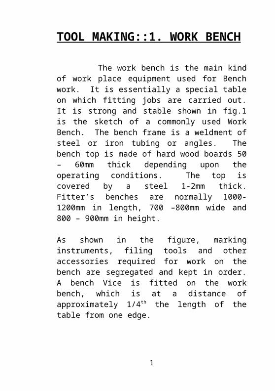
TOOL MAKING::1. WORK BENCH The work bench is the main kind of work place equipment used for Bench work. It is essentially a special table on which fitting jobs are carried out. It is strong and stable shown in fig.1 is the sketch of a commonly used Work Bench. The bench frame is a weldment of steel or iron tubing or angles. The bench top is made of hard wood boards 50 – 60mm thick depending upon the operating conditions. The top is covered by a steel 1-2mm thick. Fitter’s benches are normally 1000-1200mm in length, 700 –800mm wide and 800 – 900mm in height.
As shown in the figure, marking instruments, filing tools and other accessories required for work on the bench are segregated and kept in order. A bench Vice is fitted on the work bench, which is at a distance of approximately 1/4th the length of the table from one edge. Also, shown in is the adjustment of a bench vice according to the height of the work- man. The height is correct, if the fingers of the workman touch the chin, with the elbow placed on top of the vice jaws as shown.
1

Work Bench
Work Bench
1. Frame, 2. Bench top, 3. Vice, 4. Protective screen,5. Blueprint holder, 6. Lamp, 7.Tool tray, 8.Tool rack, 9. Drawers 10. Shelves, 11. Seat
General Safety
1. Always wear shoes in the workshop.
2. Always maintain discipline and do not indulge in mischief with co-workers.
3. Do not walk below the load carried by a crane.
2
4. Do not run in the workshop while going for an urgent call.
5. Do not work alone in the workshop.
6. Do not keep long hair.
7. Do not play with the machines.
8. Do not work during ill health.
9. Do not lift heavy jobs without the uses of cranes.
10. Protect yourself from welding arcs.
11. Report to the doctor in case of any injury and learn first aid treatment.
12. Take care of moving machines and walk within the prescribed work belt.
13. Wear a helmet in a big fabrication shop.
14. Wear proper workshop dress.
15. Wear safety goggles while working in a machine shop.
16. Wear gloves while moving sheet metal or stock with sharp edges.
3
2. VICES
Vices are holding devices extensively used for clamping of work pieces in a work shop. Most 0f the manual operations like sawing, filing, tapping, reaming etc are done by holding the work pieces in the vice.
Types of Vices:
1. Bench Vice. 2. Machine Vice.
1. Bench Vice
4
It is the most commonly used vice. The bench vice is firmly fixed on the bench. The vice consists of a cast iron body, a fixed jaw and a movable jaw, both made of cast steel. Other parts of the vice include a handle, a square threaded screw and a nut, all made of mild steel. Separate cast steel plates called as jaw plates, are fixed to the jaw by means of a screw and they can be replaced when worn out. The holding faces of the jaw plates have teeth for holding the work firmly, but this has some disadvantages for clamping of soft metals as they may get damaged. Protective grips made of Fiber, Tin plates, Lead or Aluminium, must be fitted over the jaws to prevent the serration’s from damaging the finished surface of the work piece.
Bench vices may be either of the fixed type or the Swiveling type. Both types are shown in the figure. The movement of the vice is caused by the movement of the screw through the box nut fixed under the movable jaw.
1. Bench Vice
5
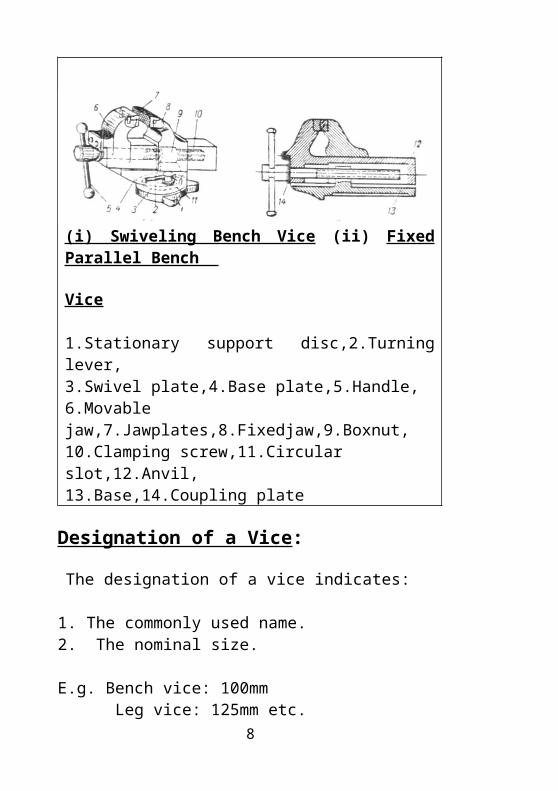
(i) Swiveling Bench Vice (ii) Fixed Parallel Bench Vice
1.Stationary support disc,2.Turning lever,3.Swivel plate,4.Base plate,5.Handle, 6.Movable jaw,7.Jawplates,8.Fixedjaw,9.Boxnut,10.Clamping screw,11.Circular slot,12.Anvil,13.Base,14.Coupling plate
Designation of a Vice:
The designation of a vice indicates: 1. The commonly used name. 2. The nominal size.
E.g. Bench vice: 100mm Leg vice: 125mm etc. The size of the vice is known by the width of its jaws. The width suitable for common work varies from 80-140mm, the maximum opening being 95mm and 180mm.
Parts of a Fixed Parallel Bench Vice:
A Bench vice consists of the following main parts:
6
Fixed Jaw: The fixed jaw as the name indicates is fixed to the base or cast along with the base of the vice. The top portion of the fixed jaw are fitted with jaw plates to help in gripping the job. The bottom portion of the Fixed jaw extends to form three lugs which help in fastening the vice to the bench. The Fixed jaw is made from Grey cast iron.
Movable Jaw:
It is a hollow inverted channel section that slides in the body of the fixed jaw and is shaped to form a jaw at its outer end. It is also made from Grey cast iron.
Base: The base is cost along with the body of the fixed jaw. The three lugs extended on the base help to fix the vice on the bench.
Screw or Spindle: Vice Spindles or Screws usually have square or Acme threads but a quick grip vice has buttress threads.It is located in the movable jaw and engages with the fixed nut or box nut, which is housed in the body of the Fixed jaw. The screw or Spindle is made of Mild steel.
Box Nut or Fixed Nut:
7
The box nut is located in the base and holds the spindle. Box nuts are made of phosphorous bronze or Grey cast iron.
Jaw Plates:
They are made from tool steel and hardened to 50-52HRC. The jaw plates are serrated suitably to hold the work.
Handle:
A Handle is used to rotate the spindle. Generally the length of the handle is 2.5 times the normal size of the vice. This slides freely in the spindle hole and does not come out because of the collar fitted at the two ends. This is made from Mild steel.
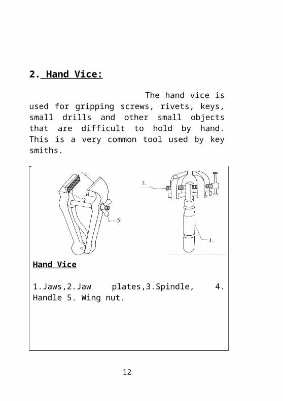
2. Hand Vice:
8
The hand vice is used for gripping screws, rivets, keys, small drills and other small objects that are difficult to hold by hand. This is a very common tool used by key smiths.
Hand Vice
1.Jaws,2.Jaw plates,3.Spindle, 4. Handle 5. Wing nut.
9
3. Leg Vice
This kind vice is usually used for forging and hammering works. The vice is secured to the top of the bench by a stop fastened to a plate bolted to the bench top. The leg of the vice is fastened to the bench leg with staples and its end fits into a hoe in the floor. There fore, the name leg vice. The construction of the vice makes it suitable for heavy work.
.Leg Vice
1.Fixed jaw,2.Hinged jaw,3.Handle,4.Spring,5.Pivot pin,5.leg,6.Lugs on base,7.Clamp
4. Machine Vice
10
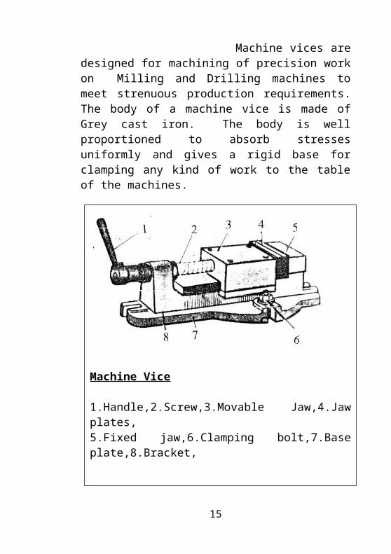
Machine vices are designed for machining of precision work on Milling and Drilling machines to meet strenuous production requirements. The body of a machine vice is made of Grey cast iron. The body is well proportioned to absorb stresses uniformly and gives a rigid base for clamping any kind of work to the table of the machines.
Machine Vice
1.Handle,2.Screw,3.Movable Jaw,4.Jaw plates,5.Fixed jaw,6.Clamping bolt,7.Base plate,8.Bracket,
5. Machine Vice with Swivel Base
11
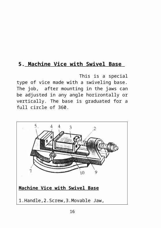
This is a special type of vice made with a swiveling base. The job, after mounting in the jaws can be adjusted in any angle horizontally or vertically. The base is graduated for a full circle of 360.
Machine Vice with Swivel Base
1.Handle,2.Screw,3.Movable Jaw,4.Jaw plates,5.Fixed jaw,6.Clamping bolt,7.Base plate,8.Bracket,9.Guide way,10.Swivel base
6. Pipe Vice:
12
1) Fixed type.
2) Open type
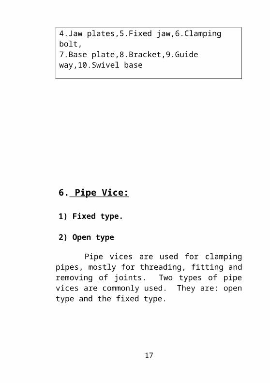
Pipe vices are used for clamping pipes, mostly for threading, fitting and removing of joints. Two types of pipe vices are commonly used. They are: open type and the fixed type.
Pipe Vice
1.Handle,2.Spindle with square thread,
3. V Jaws, 4. Base
7. Shaper’s Vice;
13

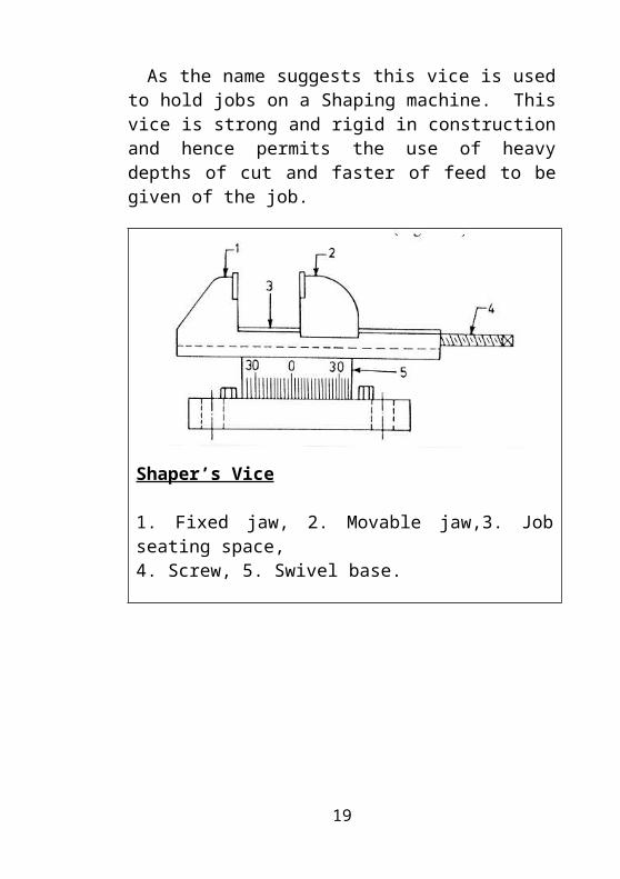
As the name suggests this vice is used to hold jobs on a Shaping machine. This vice is strong and rigid in construction and hence permits the use of heavy depths of cut and faster of feed to be given of the job.
Shaper’s Vice
1. Fixed jaw, 2. Movable jaw,3. Job seating space,4. Screw, 5. Swivel base.
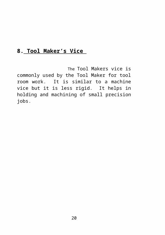
8. Tool Maker’s Vice
14
The Tool Makers vice is commonly used by the Tool Maker for tool room work. It is similar to a machine vice but it is less rigid. It helps in holding and machining of small precision jobs.
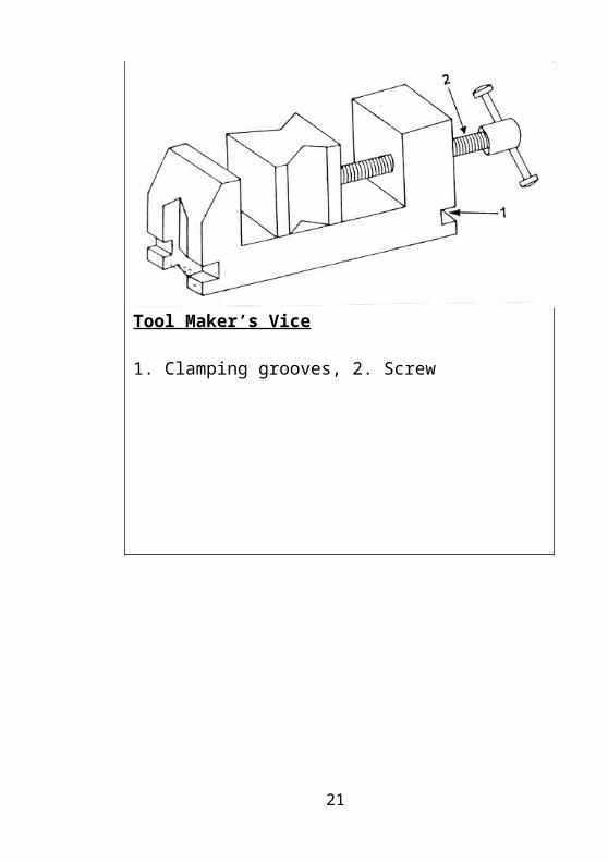
Tool Maker’s Vice
1. Clamping grooves, 2. Screw
15
Safety Precaution while using a Vice:
1.The bench vice should never be used as an Anvil. If the cast iron body cracks up, it becomes difficult to weld and be used again.
2. A hammer and other such means should never be used for extra tightening of the vice jaws as this may result in the breaking of the screw of wear out of threads.
3. Wherever possible the work should be held in the center of the jaws. This results in better gripping of the job.
4. Use soft jaws for clamping of finished components or softer materials to avoid serration marks of the jaws from falling on the work piece.
5. Always leave a small gap in between the jaw plates when the vice is not in use. The eliminates the force which would otherwise be acting on the jaw plates as well as on the spindle when the vice jaws are kept tightly joined.
Assignment:
1. What is a vice? Mention the different types of vices?
16
2. Write a brief note on bench vice?3. Neatly draw the sketch of bench vice and
mention its different parts?4. Briefly explain each part of bench vice?5. How vices are designated? Give two examples?6. Neatly sketch hand vice and explain briefly?7. Explain briefly leg vice with a neat sketch?8. Write a brief note on machine vice?9. Write a brief note on machine vice with swivel base?
10. Mention differences between machine vice and machine vice with swivel base?
11. Write a brief note on (a) pipe vice (b) shaper’s vice (c) tool makers vice.
12. Mention some important safety precautions while using a vice.
17

3. FILES
A File is a hand cutting tool used to remove excess aterial and to produce a finished surface. It is made up of High Carbon Steel and has teeth cut on its face in slanting rows. It is hardened to about 60-62 HRC and the tang portion is left soft. The tang portion of the file fits into handle made of plastic or wood.
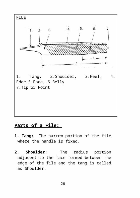
FILE
1. Tang, 2.Shoulder, 3.Heel, 4. Edge,5.Face, 6.Belly7.Tip or Point
18
Parts of a File:
1. Tang: The narrow portion of the file where the handle is fixed.
2. Shoulder: The radius portion adjacent to the face formed between the edge of the file and the tang is called as Shoulder.
3. Heel: The uncut portion on the face near the shoulder of the shoulder of the file is termed as the Heel.
4. Edge: It is the perpendicular side of the face. The edge is always single cut. Some times the teeth are not cut on the edge and are called as Safe edge files.
5. Face: It is the surface of the file where the teeth are cut .
Types of Files.
a. Flat File It is rectangular in cross section and is tapered towards the tip in both 19idth and thickness. Teeth are cut on both faces of the file and also on its edges. It is widely used for general purpose work.
b.Hand File
19
These are similar to flat files but are parallel in width and thickness. They are some times tapered in thickness only. One of its edges do not have teeth cut on them. This file is used for filing flat surfaces, the safe edge being useful when filing up to the shoulder.
c.Half Round File This file is flat on one side and curved on the other side. So, it can be used on both flat and curved surfaces.d.Knife Edge File
This file is shaped like a knife and is tapered in width and thickness with two faces at 150 angles each. It is mainly used by lock smiths for filing acute angles more than 150.
e.Round File
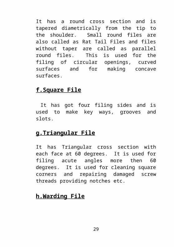
It has a round cross section and is tapered diametrically from the tip to the shoulder. Small round files are also called as Rat Tail Files and files without taper are called as parallel round files. This is used for the filing of circular openings, curved surfaces and for making concave surfaces.
f.Square File
It has got four filing sides and is used to make key ways, grooves and slots.
g.Triangular File
20
It has Triangular cross section with each face at 60 degrees. It is used for filing acute angles more then 60 degrees. It is used for cleaning square corners and repairing damaged screw threads providing notches etc.
h.Warding File
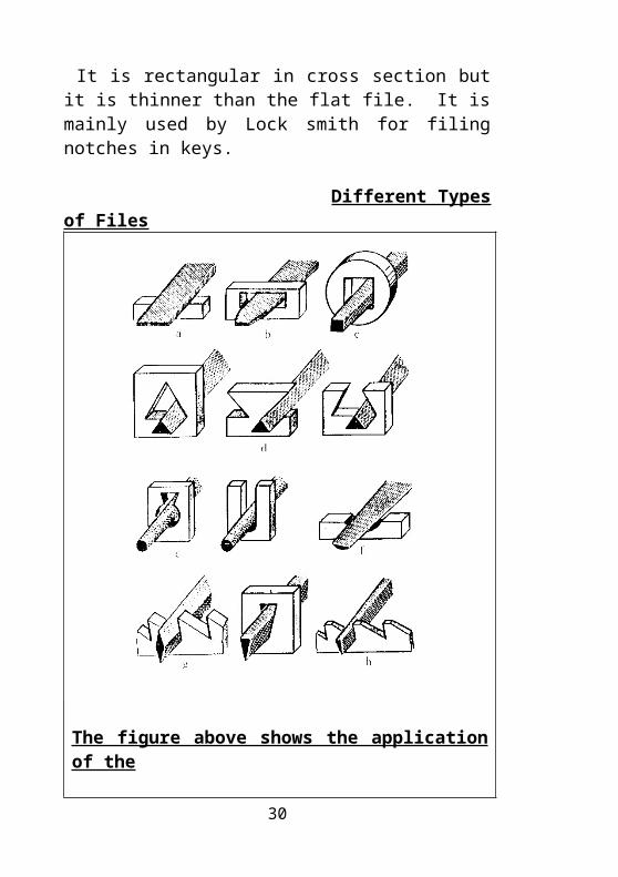
It is rectangular in cross section but it is thinner than the flat file. It is mainly used by Lock smith for filing notches in keys.
Different Types of Files
21
The figure above shows the application of the
different file types
a. Hand file, b. Flat file, c. Square file,d. Triangular file, e. Round file ,f. Half round fileh. Knife edge File.
Different Types of Files
Cross Section of Files
22

23
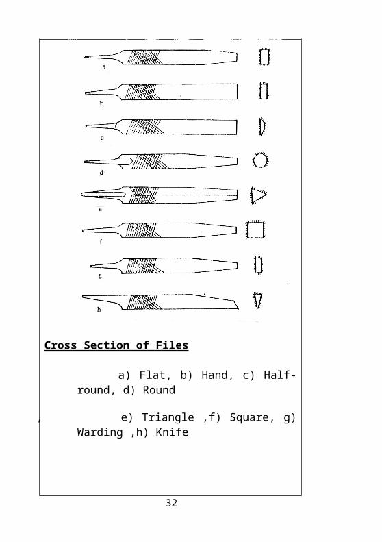
Cross Section of Files
a) Flat, b) Hand, c) Half-round, d) Round
, e) Triangle ,f) Square, g) Warding ,h) Knife
24
Elements of the File:
1.Safe Edge:
The flat file will have single cut teeth on its edges. Hand files usually have teeth cut on one of its edges. The other end is ground and left uncut or safe. This uncut edge of a file is termed as safe edge.
2.Convexity Of Files:
All the files are made with the face slightly convex on the thickness and along the length. It is done so because, while filing a broad surface, the application of pressure will be on both the ends of the file. There is a tendency of the file to bend towards the pressure exerted and hence flatness of the job may not be achieved.
3.Taper of the File:
The reduction in width of the file from the tip portion towards the belly is called as the Taper of the file.
25
Methods of Filing:
a) Cross Filing,.b)straight Filing, c)Draw Filing.
1.Cross Filing
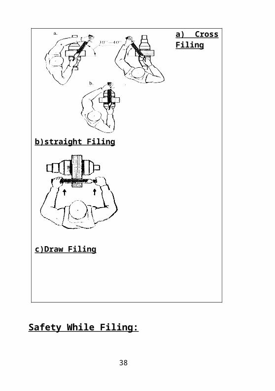
In Cross filing the filing strokes run alternatively from left to right and right to left at an angle of 40-600 to horizontal. This is a common method adopted in the workshop to remove excess material and to get a fine surface finish. Also in this method, the possibility of rounding off of the edge of the job is minimized and the score marks made in the work by the file teeth are crisscrossing. Due to the increased contact area maximum amount of material can be removed.
2. Straight Filing:
In straight filing, the file is removed at right angles to the length of the job. On the back stroke, the pressure on the file is lifted clear of the work in order not to blunt the teeth. Straight filing is especially useful on long and narrow pieces of work whose width is less than that of the file. The filing speed varies from 30-40 strokes per minute.
26
3.Draw Filing:
When it is desired to file a piece of work length wise, it may be done by draw filing. In this method the handle of the file is not held. Instead, both ends are placed close together on the file as shown in the figure. The file is placed at right angles across the work piece while the hands and especially the thumbs grip the file and move it up and down the length of the material. It does not remove much material, but a smoother cutting action is achieved than with a cross or straight file. This method is mainly used to remove the material from thin sheets very lightly. Single cut files are used for Draw filing.
27
Methods of Filing:
a) Cross Filing,.b)straight Filing,c)Draw Filing
28
a) Cross Filing b)straight Filing
c)Draw Filing
Safety While Filing:
29
1. Apply pressure while filing only in the forward direction as retaining the pressure on the reverse direction causes the teeth to become blunt.
2. After filing, clean the file using a file brush. This enables the clogged material to clear off the cutting edges of the file.
3. Do not apply excessive pressure while working with a smooth file.
4. Do not use one kind of file for all types of work.
5. Do not use a file without a handle as this may result in injury to the hands.
6. Use a new file gently on metals like gun metal, bronze, aluminum etc. the first few strokes.
Assignment:
1. What is a file? Mention the different parts of file and explain each part briefly?
2. Draw a neat sketch of flat file and mention the parts ?
3. Mention different types of files? Explain each in brief?
4. Neatly sketch the different types of files with their cross section?
5. Explain briefly the elements of a file?6. Briefly explain methods of filing?Mention some important safety precautions while filing
30
4. HACKSAW
The Hand Hacksaw is a hand cutting tool generally used for cutting materials like, thick metal sheets, round bar stock and other sections, and to cut slots, contours etc.
Parts of a Hand Hacksaw:
The Hacksaw mainly consists of two parts.They are: 1. Frame, 2. Blade
1. Frame:
The Frame is that part is the Hacksaw, which holds the blade. The Frame is available as a Flat type, Tubular type or Deep cutting type. Among all these three types, Fixed and Adjustable varieties can also be found. The parts of an Adjustable Flat Frame are explained below.
Parts of the Frame:
a.Body:
The body of the frame is made from either a tube, a solid flat strip or a round bar and may be of the fixed type or adjustable type. Wooden handles are generally used. Pistol grip steel frame handles are also used for the frame.
31
b.Tension Screw:
As the name suggests this screw is used to adjust the tension of the blade. It is present opposite to the handle. The wing nut tightens on the tension screw.
c.Wing Nut:
It is so named because it has the appearance of a housefly wing. This is driven by the thumb on the tension screw and this pressure is enough to keep the blade in tension. No extra leverage is necessary.
d.Pins:
Two pins are provided at the ends of the frame. These pins enable the blade to be fixed to the frame.
32

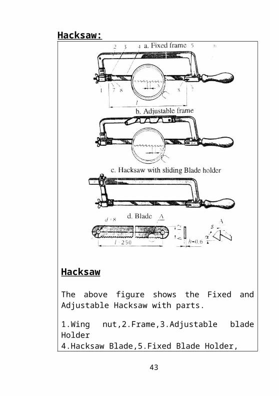
Hacksaw:
Hacksaw
The above figure shows the Fixed and Adjustable Hacksaw with parts.
1.Wing nut,2.Frame,3.Adjustable blade Holder4.Hacksaw Blade,5.Fixed Blade Holder,
6.Handle,7.Pins,8.Slits
2. Blade 33
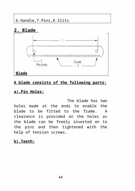
Blade
A blade consists of the following parts:
a).Pin Holes:
The blade has two holes made at the ends to enable the blade to be fitted to the frame. A clearance is provided on the holes as the blade can be freely inserted on to the pins and then tightened with the help of tension screws.
b).Teeth:
The serrations cut across the thickness of the blade, generally on one of its edges, are called as the teeth of the blade. The teeth provide the cutting edges of the blade. There are different types arrangements or placement of the teeth on the blade and are called as saw settings. These are explained later in this chapter.
c).Toothed Edge
The longitudinal edge along with the teeth is called as the toothed edge.
34

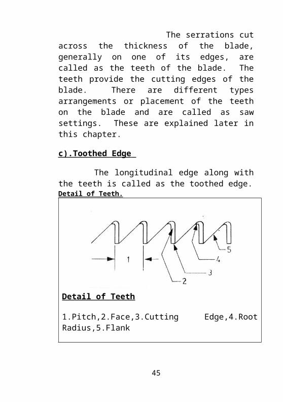
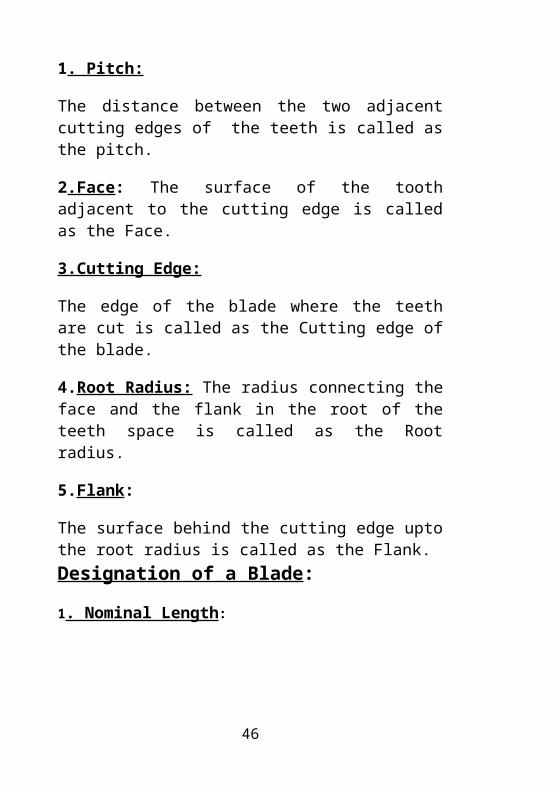
Detail of Teeth.
Detail of Teeth
1.Pitch,2.Face,3.Cutting Edge,4.Root Radius,5.Flank
1. Pitch:
The distance between the two adjacent cutting edges of the teeth is called as the pitch.
2.Face: The surface of the tooth adjacent to the cutting edge is called as the Face.
3.Cutting Edge:
The edge of the blade where the teeth are cut is called as the Cutting edge of the blade.
4.Root Radius: The radius connecting the face and the flank in the root of the teeth space is called as the Root radius.
5.Flank:
The surface behind the cutting edge upto the root radius is called as the Flank.Designation of a Blade:
35
1. Nominal Length:
The length between the outer edges of the pin holes measured along the center line of the blade is the blade’s nominal length.
2. Width:
It is the distance between one edge to the other edge of the blade.
Types of Blades:
Blades may be of the following types:
1. All hard blade : It is fully hard except near the pin holes.
2. Flexible blade: It is hardened at the teeth portion only.
3. Flexible center blade : It is hardened at the back and at the teeth only.
4. Spring back blade : It is hardened at the teeth and the remaining portion is spring tempered.
Classification of a Blade:
36
Hacksaw blades are classified according to the following:
1. The commonly used name whether hand or machine operated
2. The nominal length, width and thickness.
3. The pitch or teeth per inch.
4. The material whether H.S.S ( High speed steel), H.C.S (High carbon steel) or L.S.S ( Low alloy steel).
5. The type of blade; whether All hard, Flexible, Flexible center or Spring back.
Example:
The hacksaw blade for hand operation having a length of 300mm, a width of 13mm, thickness of 0.63mm and a pitch of 0.8mm of Low alloy steel and All hard, shall be specified as:
“Hand saw blade 250 X 13 X 0.63/0.8-L.A. All hard”.
“Hand saw 12” x ½” x 1mm x 18 T.P.I (H.S.S)”
Saw Setting:37
The arrangement of the saw teeth in a regular fashion is called as Saw setting. Setting the teeth of the Saw blade is done in order that the width of the slot cut may be slightly larger than the blade thickness. This provide a clearance between the blade and the slot and thus prevents the jamming of the blade. This makes cutting much easier. According to the pitch of the blade, there are different types of Saw settings:
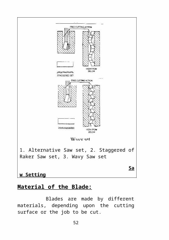
There are three different types of saw setting (Fig 18): 1. Alternative Saw set (Fig. 18 a) 2. Staggered of Raker Saw set (Fig. 18 b) 3. Wavy Saw set
1. Alternative Saw Set
This type of setting is generally used on blades having a pitch of 1.6 mm. In this type, the teeth are set alternatively that is 1 teeth is bent on one side and the next teeth on the opposite side.
2 .Staggered or Raker Saw Set
This type of setting is used in blades having a pitch of 1to 1.25mm. Here, one teeth is bent to one side, the next teeth is straight and unset, the third teeth is bent to the opposite side of the first teeth and the fourth teeth is again straight and unset. The same pattern is found along the entire length of the blade barring 30mm from either edge of the blade. Raker set blades is used for general purpose sawing.
3. Wavy Saw Set
38
Hack saw blades with a pitch of 0.8mm are wavy set that is two or three consecutive teeth are bent alternatively to opposite sides by 0.25 to 0.6mm. The teeth of the blade look like a wave and hence the name wavy set. This type of set is used on blades to cut thin sheet metal sections.
1. Alternative Saw set, 2. Staggered of Raker Saw set, 3. Wavy Saw set
Saw Setting
Material of the Blade:39
Blades are made by different materials, depending upon the cutting surface or the job to be cut.
1. High Carbon Steel Blades:
These blades have a hardness of 60to62 HRC. It is used to cut mild steel, brass, copper, aluminum etc. A cutting sped of 35 strokes per minute is specified for these blades
2. High Speed Steel Blades:
These blades have a very high wear resistance and an ability to cut harder material. These blades have an HRC of 62 to 65. It is used to cut alloy steels and tool steels. A cutting speed of 65 strokes per minute is specified for these blades.
3. Low Tungten Alloy Steels Blades:
These blades have an hardness of 61-65 HRC and is used to cut mild steel and carbon steel. These blades are wear resistant, cut faster and last longer. Hence they are much economical than carbon steel blades. A cutting speed of 40 to 55 strokes per minute is specified for these blades.
Assignment:
40
1. What is a hacksaw? Draw a neat sketch of hand hacksaw and mention the different parts?
2. Briefly explain the parts of the frame of the hacksaw?
3. Briefly explain the parts of the blade that is used while hacks awing?
4. Mention the types of blades?
5. How blades are classified. Explain with an example?
6. Explain briefly saw setting?
7. What are the different types of saw setting. Explain briefly each with a neat sketch?
8. What are the different types of materials used to manufacture the blade. Explain each in brief?
9. Mention some important safety precautions while sawing?
Safety Precautions While Sawing:
41
1. Before sawing, make a groove or notch with a triangular file to position the blade on the marked for cutting the slot.
2. Ensure that the blade is properly tightened, and the job is held securely in the vice.
3. Fine pitch blades should be used while cutting hard materials and coarse pitch blades for soft materials.
4. Relieve the cutting pressure on the return stroke.
5. Reduce the cutting pressure when the blade is almost about to cut the job.
6. Start cutting from a new edge if the blade breaks in the middle.
7. To prevent chattering, cut as close as possible to vice jaws.
8. Use full length of the blade during sawing.
9. While sawing, make continuous strokes.
10. While sawing thin sheets, keep wooden boards as support.11.While sawing, ensure that at least three teeth are in contact with the job.
42
5. CHISELS
A chisel is a hand cutting tool used to chip off excess layers of stock from the surfaces of work pieces by using a hammer. The chisel is considered outdated today, due to the advent of modern machine tools. However there are occasions when a chisel becomes indispensable.
Chipping is resorted to when machining is impractical and high accuracies are not required. Typical chipping applications include removal of large surface irregularities, hard skins, burrs, sharp edges from castings and stampings, cutting key ways, oil grooves, preparing the edges of cracks for welding up, cutting of the heads of rivets for their removal, making holes in sheet metal and so on.
Common Types of Chisels:
The following are the common types of chisels that we can come across in a machine shop:1. Flat2. Cross-cut (cape)3. Diamond point4. Round nose5. Cow mouth ( Gouge)6. Side cut
43
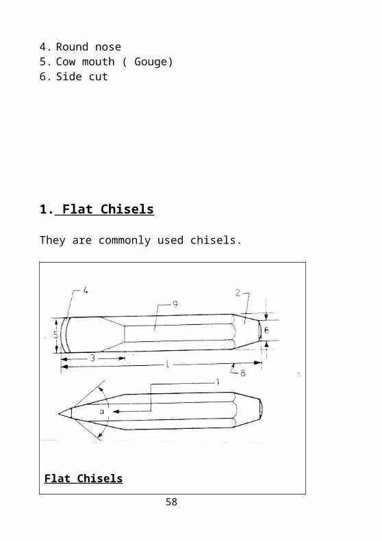
1. Flat Chisels
They are commonly used chisels.
Flat Chisels
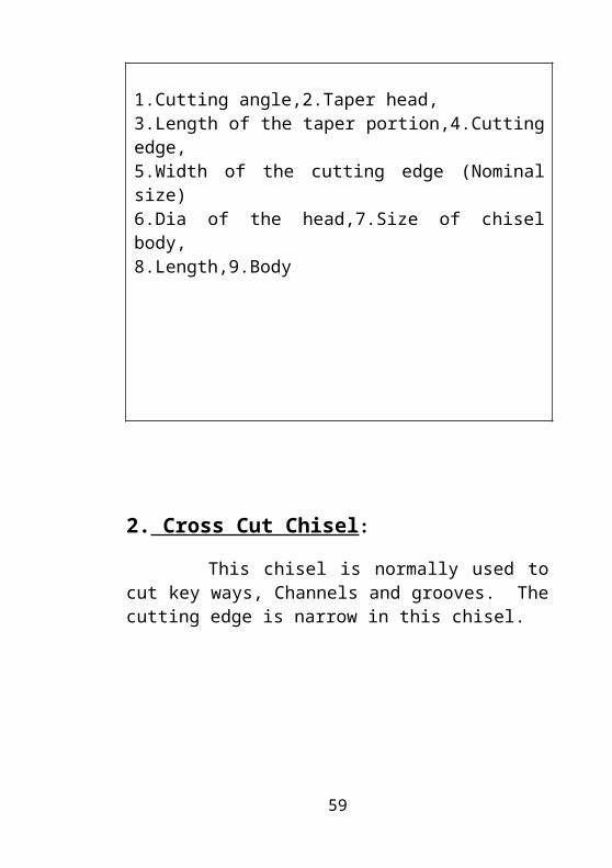
1.Cutting angle,2.Taper head,3.Length of the taper portion,4.Cutting edge,5.Width of the cutting edge (Nominal size)6.Dia of the head,7.Size of chisel body,8.Length,9.Body
44
2. Cross Cut Chisel:
This chisel is normally used to cut key ways, Channels and grooves. The cutting edge is narrow in this chisel.
Cross Cut Chisel
1.Width of cutting edge,2.Dia of head,3. Size of body 4.Length, 5.Cutting angle,6.
Size of the chisel body
45
3. Diamond Point Chisel;
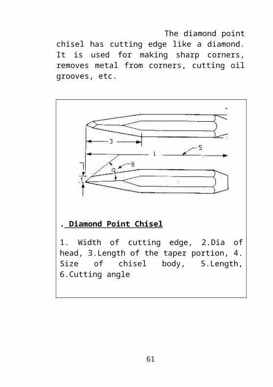
The diamond point chisel has cutting edge like a diamond. It is used for making sharp corners, removes metal from corners, cutting oil grooves, etc.
. Diamond Point Chisel
1. Width of cutting edge, 2.Dia of head, 3.Length of the taper portion, 4. Size of chisel body, 5.Length, 6.Cutting angle
46
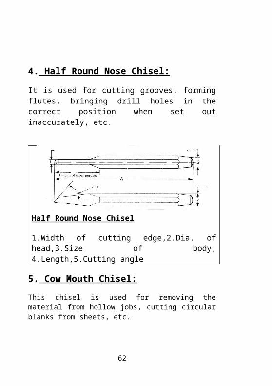
4. Half Round Nose Chisel:
It is used for cutting grooves, forming flutes, bringing drill holes in the correct position when set out inaccurately, etc.
Half Round Nose Chisel
1.Width of cutting edge,2.Dia. of head,3.Size of body, 4.Length,5.Cutting angle
5. Cow Mouth Chisel:
This chisel is used for removing the material from hollow jobs, cutting circular blanks from sheets, etc.
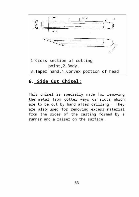
1.Cross section of cutting point,2.Body,3.Taper hand,4.Convex portion of head
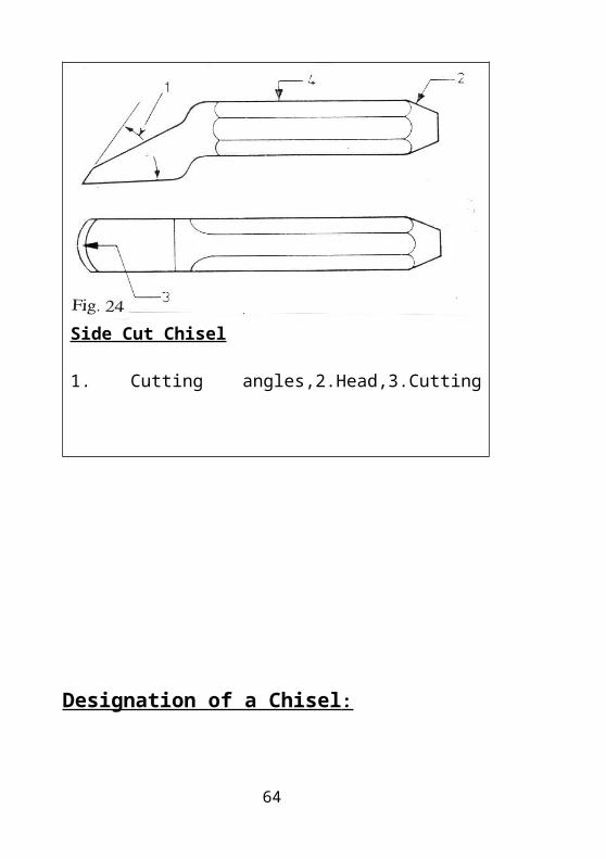
6. Side Cut Chisel:47
This chisel is specially made for removing the metal from cotter ways or slots which are to be cut by hand after drilling. They are also used for removing excess material from the sides of the casting formed by a runner and a raiser on the surface.
Side Cut Chisel
1. Cutting angles,2.Head,3.Cutting Edge,4.Body
Designation of a Chisel :
48
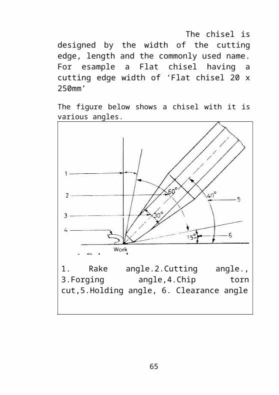
The chisel is designed by the width of the cutting edge, length and the commonly used name. For esample a Flat chisel having a cutting edge width of ‘Flat chisel 20 x 250mm’
The figure below shows a chisel with it is various angles.
1. Rake angle.2.Cutting angle., 3.Forging angle,4.Chip torn cut,5.Holding angle, 6. Clearance angle
Safety While Chiseling:
1. Always chip towards the fixed jaw of the vice.
49
2. Before chipping, it is necessary to file a chamfer on the job to give seating to the chisel.
3. Chamfer the job from both the sides in case of a cast iron block, if the chipping to run up to the other end. Otherwise, due to the brittle quality of the metal, the corner of the job will be rooted out in the end.
4. Do not take too deep a cut. A cut approximately 1 ½ mm deep is enough.
5. For heavy chipping, use a leg vice.
6. To cut off the heavy rivet head, cut a groove in the head with a hacksaw frame or a cross cut chisel and then remove the excess metal with a Flat or side cut chisel.
Assignment:
1. What is a chisel? Why it is used?
2. Mention the common types of chisel. Explain each in brief with a neat sketch and name the parts?
3. How chisels are designated?
4. Mention some safety while chiseling
6. HAMMERS
50
Hammers are one of the most primitive tools that are in use today. They have a metallic head with a wooden handle. They are used for punching, bending, striking, riveting and forging.
They are made of alloy steel having 0.6 percent of carbon and are usually drop forged. Hammers have hardness 43 – 51 HRC.
Types Of Hammers:
51
The following are the common types of hammers in use:
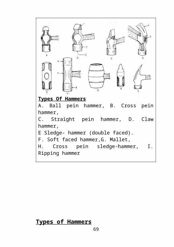
Types Of HammersA. Ball pein hammer, B. Cross pein hammer,C. Straight pein hammer, D. Claw hammer, E Sledge- hammer (double faced).F. Soft faced hammer,G. Mallet,H. Cross pein sledge-hammer, I. Ripping hammer
Types of Hammers
52
1.Ball Pein Hammer
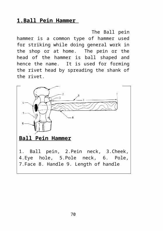
The Ball pein hammer is a common type of hammer used for striking while doing general work in the shop or at home. The pein or the head of the hammer is ball shaped and hence the name. It is used for forming the rivet head by spreading the shank of the rivet.
Ball Pein Hammer
1. Ball pein, 2.Pein neck, 3.Cheek, 4.Eye hole, 5.Pole neck, 6. Pole, 7.Face 8. Handle 9. Length of handle
2.Cross Pein Hammer:
53
The pein of this hammer is flat and is perpendicular to the handle. It is used for bending sheet, binding, providing collars etc.
3.Claw Hammer :
This hammer head has a cut in the center and is bent to a sharp curve. It is used for pulling nails out of wood with the help of the head while the face is same as that of a ball pein hammer. This is mostly used by cobblers and carpenters. Some times the pein has a small curve on the claw and is called as a Ripping hammer.
4.Mallet Hammer: A wooden hammer is called a mallet. It is used by carpenters to drive their tools and by sheet metal workers for bending thin sheets.
5.Straight Pein Hammer:
The pein of this hammer is parallel to the handle. It is used for stretching of metal, working of corners etc.
6. Sledge Hammer:
Sledge hammer are used by black smiths, wood cutters, stone breakers, fabricators, etc. For heavy jobs. There are Three types of sledge hammer. They are :1,Double faced,2.ross pein,3.Straight pein
8.Soft Hammer :It is made up of soft metals like copper, aluminum, lead etc. It is used for hammering finished jobs specially in an assembly shop.
54
The Following are the Main Parts of a Hammer
1. Cheek:
The flat portions on both sides in the middle of the hammer head are called as cheeks. Here the manufacturer’s name, weight etc. is stamped.
2. Eye Hole :
The hole provided for fixing, the handle is called as the Eye hole. It is oval and tapered from both the ends to the middle. The hole is oval so that the hammer should not rotate in the handle and it is tapered for better grip.
3. Face:
The flat portion in the front which strikes the job is called as the Face. This is hardened and tempered to 41 to 53HRC to a maximum of 13mm length. The face has a small curve that helps in striking at the exact position.
4.Handle:
It is the holding portion and is made of wood and is introduced in to the eye hole and is secured firmly with the help of the handle wedges.
5.Pein:
It is that part of the hammer which is opposite to the face. The Pein is used for riveting, and peening.
55
6.Pein Neck:
It is the radius portion joining the pein and the center of the metallic head.
7.Pole Neck:
It is the radius portion joining the pole and the center body of the metallic head.
8.Pole:
The cylindrical portion adjacent to the face is called the pole. It is hardened near the face.
Hammers are designated according to the following :
a) Type of hammer
b) Weight of hammer and
c) Pein
Eg. ‘0.5 kg. Straight pein hammer’
Hammers are available in various weights like 0.25kg, 0.5kg and 1kg for common hammers and 2-10kg for sledge hammer.
Safety Precautions while Hammering:
1. Handle should be properly fixed.
56
2. Select a hammer of correct weight for a suitable job.
3. Check the handle head for cracks.
4. The face of the hammer should be free from oil.
Assignment:
1. What is hammer? Why it is used?
2. What is the percentage of carbon present in the hammer and mention its hardness?
3. What are the different types of hammers. Explain each in brief with a neat sketch?
4. Draw a neat sketch of ball peen hammer and explain its parts in brief?
5. How hammers are designated?
6. Mention some safety precautions while hammering?
7. SCRAPERS
57
Scrapers are special cutting tools usually made of High carbon steels. The cutting end is hardened. With out tempering to 56-64 HRC. Scraping is an operation of removing very thin layers of metal with a Scraper. The purpose of scraping is to ensure a tight leak proof contact of mating surfaces in a joint. Scraping is applicable to both flat and curvilinear surfaces. Scraping is uslly done by hand. Scrapers are available in various froms and are explained below.
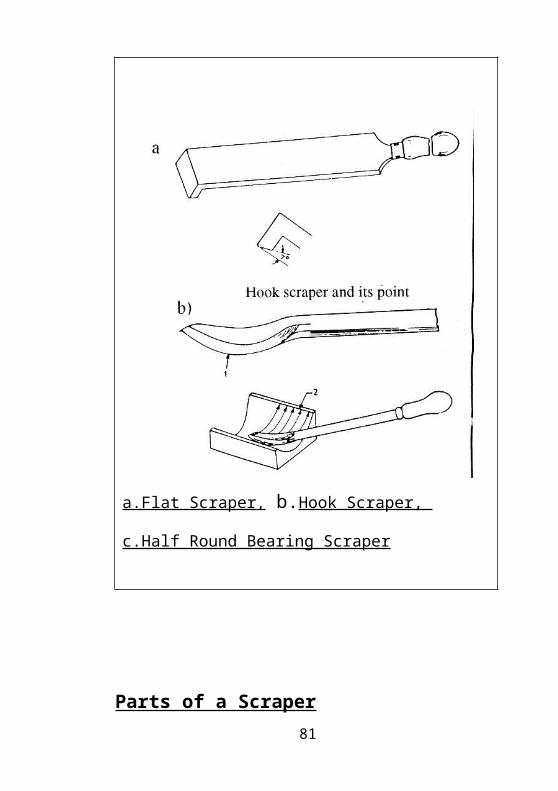
1.Flat Scraper
This is the most commonly used scraper. The body of this scraper is forged or machined from mild steel. The length of blade is about 30-35 mm. The blade must have a slight curvature of the cutting edge and the corners are round which help the user to scrape exactly the high spots desired. Scrapers are manufactured in different lengths. 200 and 300mm scrapers are most commonly used.
2.Hook Scraper
This is similar to a flat scraper except that its cutting end is bent to form a cutting edge. This is used for frosting, flanking and producing various designs on the bed parts, surface plates, machine columns and other jobs.
3.Half Round Bearing Scraper
58
This scraper is called half round because the body is curved. This scraper is used for scraping curved and cylindrical surfaces, split bearings, big bush bearings, etc.
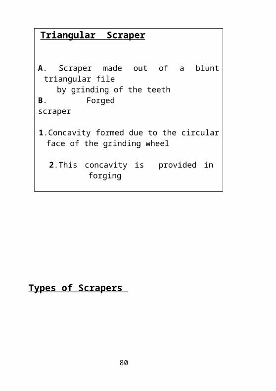
4.Triangular Scraper
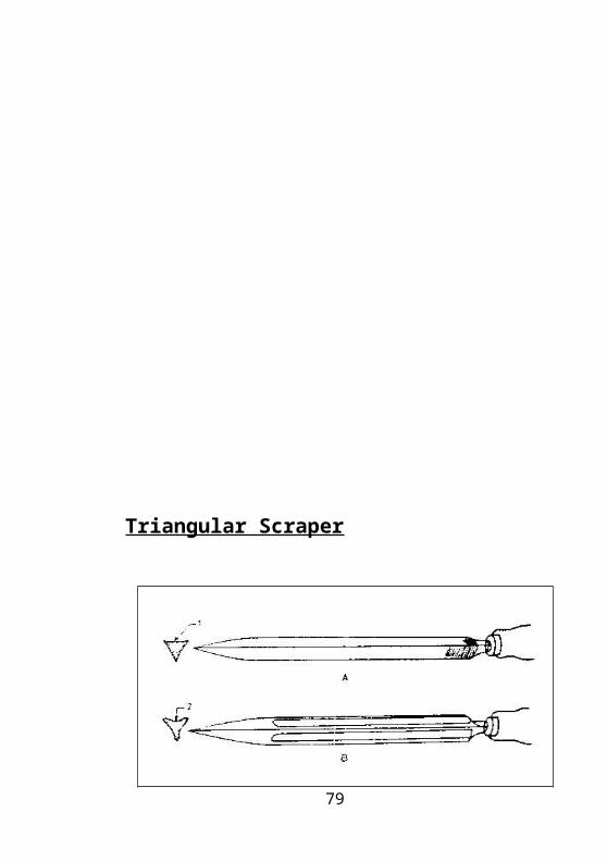
The shape of this scraper is triangular. This scraper is used for scraping curved surfaces, holes and bores. It is also used for removing sharp edges which are formed after machining. Scrapers can be made in the shop floor by grinding the worn out faces of triangular files.
Triangular Scraper
59

Triangular Scraper
A. Scraper made out of a blunt triangular file by grinding of the teethB. Forged scraper
1.Concavity formed due to the circular face of the grinding wheel
2.This concavity is provided in forging
Types of Scrapers
60
a.Flat Scraper , b.Hook Scraper,
c.Half Round Bearing Scraper
Parts of a Scraper
61
Parts of Scrapers
1. Tang, 2.Edge 3.Body 4.Point 5.Face or End,6. Heel,7.Cutting Edge
Marking Media:62
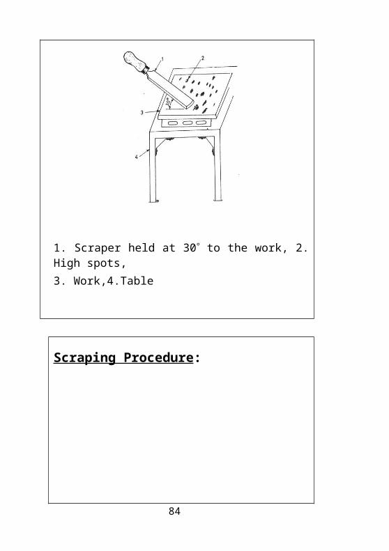
A marking media is very important in a scraping operation to find the high spot. The marking media is usually a paste or a powder and is very fine. It should spread uniformly on the surface plate. Prussian blue is the most commonly used marking media. It is a concentrated blue oil paint used for colouring by artist. This substance gives clear, sharp, distinct markings.
1. Scraper held at 30 to the work, 2. High spots,
3. Work,4.Table
63
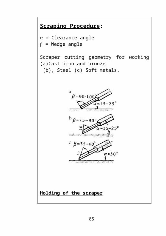
Scraping Procedure:
= Clearance angle = Wedge angle
Scraper cutting geometry for working (a)Cast iron and bronze (b), Steel (c) Soft metals.
Holding of the scraper
64
Scraping Procedure:
1. Clean the surface plate thoroughly.
2. Rough scrape the job with the scraper held at an angle of 10 – 30 to the surface of the work.
3. A thin layer of marking medium is applied on the surface plate.
4. The rough scraped job is cleaned and then slid on the surface plate to check for the high spots. The marking medium sticks on to the high spots on the job.
5. After the high spots are found, scrape of a little larger area then that occupied by the high spots.
6. Repeat the operation of applying the marking medium and scraping.
7.Press the scraper on the surface of the job with one hand and make short strokes of 10-25 mm holding it at the proper angle.
8. Take the strokes with the scraper in one direction and keep on changing the direction after completion of one stroke.
9. As the process is carried out gradually it will be found that the whole area will be covered by spots of marking medium.
65
10. The distance between the high spots called, as the pitch should be about 4-6mm. Jobs with such a pitch of high spots are considered to be scraped well.
Safety while Scraping;
1. Before starting to scrape checks and makes sure the amount of stock to be scraped.
2. Dipping the scraper occasionally in turpentine or kerosene will help to cut easier and better. this cleanse the scraper of accumulated dust, dirt and metal cuttings.
3. The master plate are straight edge should be kept at a controlled temperature.
Assignment:
1. Briefly explain what are scrappers?
2. What are the different types of scrappers. Explain each in brief?
3. Briefly explain the procedure of scrapping?
4. Mention some safety while scrapping?
66
8. SCREW DRIVERS
Screwdrivers are one of the most commonly used hand tools in a workshop and at home. Screwdrivers are used to loosen and tighten socket head screws.
Types of Screwdrivers:
1.Cabinet Screwdrivers:
Cabinet screwdrivers are used for driving wooden screws. The handle is made flat on both the sides to get an extra grip to drive the screws in wood. These screwdrivers are generally used by carpenters.
2.Electrician’s Screw Drivers
This screw driver is similar to a standard screw driver but as longer and thinner shank and is insulated. These screwdrivers have a mechanism in them to test the current flow.
3.Off- Set Screwdriver
It has a bent shank with points on the both ends. It is used for driving screws that cannot be reached with a straight shank screwdriver.
4.Phillips Screw Driver:
The tip of the screwdriver has slots and is cross-shaped. This is commonly referred to as a star screwdriver. It has a better grip than a standard screwdriver and also prevents damages to heads.
67
5.Ratchet Screwdriver
This screwdriver is used for obtaining a faster motion while rotating the screw. The ratchet is fitted to the handle. The hand is not lifted for a fresh motion to turn the screw clockwise or anti clockwise. Some screwdrivers have a worm type shank and are operated by pushing the handle down. Such screwdrivers are called as quick motion screw ratchet screwdrivers.
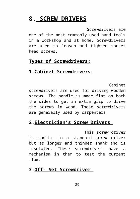
6.Standard Screw Driver
the standard screwdriver is used for general purpose work. Some standard screwdrivers are equipped with strong shanks and rigid handles for heavy-duty work. The figure below shows the various types of screwdrivers
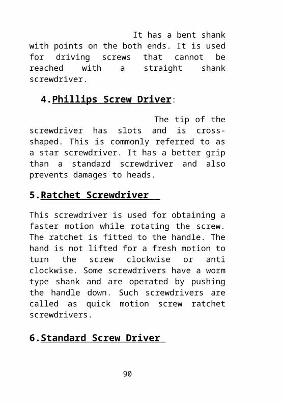
Standard Screw Driver
68
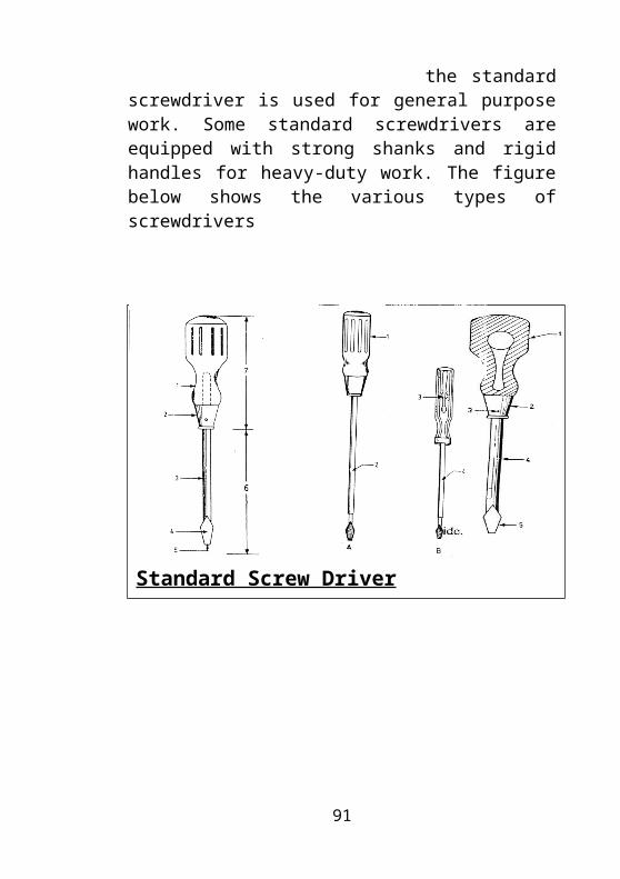
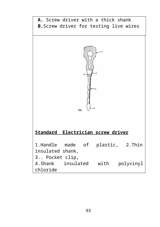
Standard screw driver Electrician screw driver
Standard screw driver Electrician screw driver1.Handle,2.Ferrule,3. Round shank,4 Blade,5.Point, 6.Length of shank,7. Length of handle A. Screw driver with a thick shank B.Screw driver for testing live wires
69
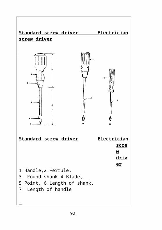
Standard Electrician screw driver
1.Handle made of plastic, 2.Thin insulated shank,3.. Pocket clip, 4.Shank insulated with polyvinyl chloride
70
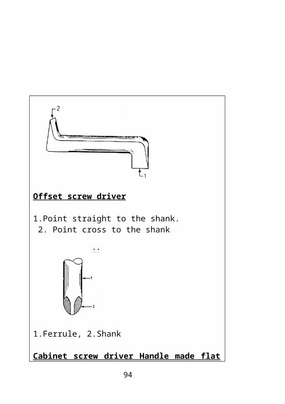
Offset screw driver
1.Point straight to the shank. 2. Point cross to the shank
1.Ferrule, 2.Shank
Cabinet screw driver Handle made flat shown in the center
71
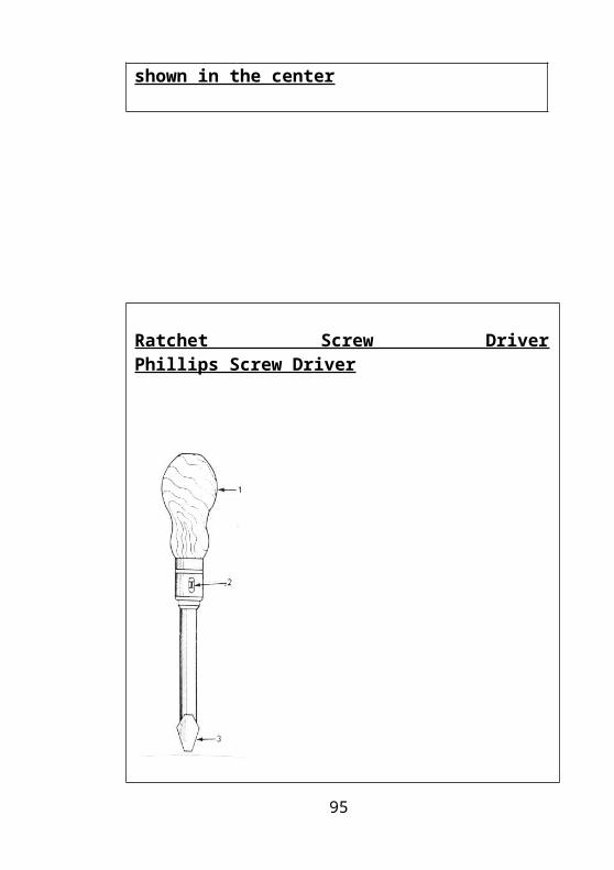
Ratchet Screw Driver Phillips Screw Driver
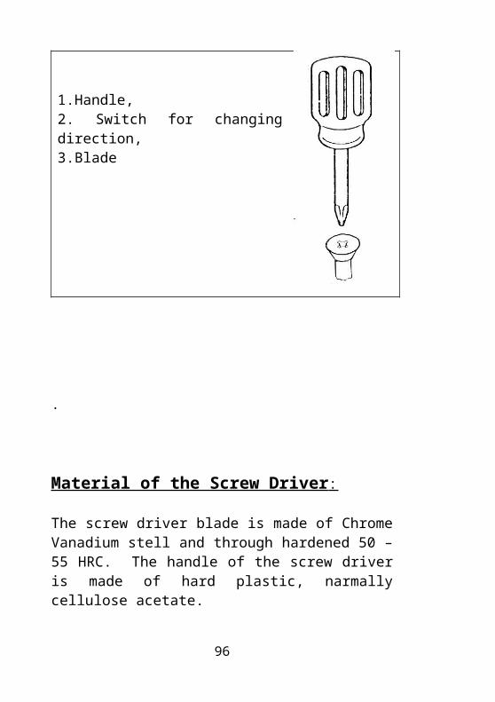
1.Handle, 2. Switch for changing direction,3.Blade
.
72
Material of the Screw Driver :
The screw driver blade is made of Chrome Vanadium stell and through hardened 50 –55 HRC. The handle of the screw driver is made of hard plastic, narmally cellulose acetate.
Size of the Point and Specification of a Screw Driver :
The point of the blade of a screw driver should not be more than the length of the slot on the screw head. A screw driver may be specified by the type, length of the shank, and the dimensions of the point.Eg: standard screw driver 100mm x 1 x 6.5’Where 100mm is the length of the shank, 1mm is the thickness of the point and 6.5mm is the width of the point.
Safety while Driving:
1. Do not use the screw driver as a pin punch and do not hammer on the handles.
2. Do not use the screw driver as a lever.
3. Do not use the flat blade screw driver on a phillips screw head and vice versa.
4. Use the right size of screw driver for each screw.
5. Use only the electrician screw driver while working with electrical wires and equipment’s.
73
Assignment:
1.Mention the different types of screwdrivers?
2.Briefly explain types of screwdrivers with a neat sketch with labeled parts?
3.What is the material of screwdriver? How screwdrivers are specified?
4.Mention some safety while driving screws?
74
9. WRENCHES AND SPANNERS
Wrenches or spanners are used mainly for fastening purpose. They are use for tightening and loosening of nuts and bolts, pipes etc. There are different type of wrenches. Some wrenches are also called spanners. Spanners are made from Chrome Vanadium steel and are usually dropped forged. They are specified by their type and the size of the jaw opening. This differs for fixed and adjustable wrenches. Spanners are of the following type:
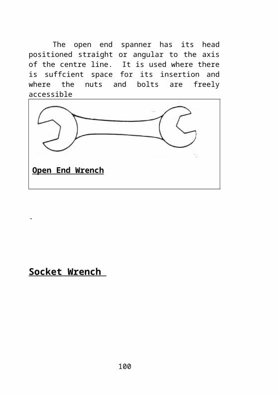
Open End Wrench
The open end spanner has its head positioned straight or angular to the axis of the centre line. It is used where there is suffcient space for its insertion and where the nuts and bolts are freely accessible
Open End Wrench
.
75
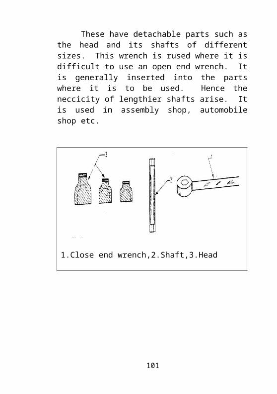
Socket Wrench
These have detachable parts such as the head and its shafts of different sizes. This wrench is rused where it is difficult to use an open end wrench. It is generally inserted into the parts where it is to be used. Hence the neccicity of lengthier shafts arise. It is used in assembly shop, automobile shop etc.
1.Close end wrench,2.Shaft,3.Head
76
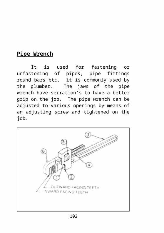
Pipe Wrench
It is used for fastening or unfastening of pipes, pipe fittings round bars etc. it is commonly used by the plumber. The jaws of the pipe wrench have serration’s to have a better grip on the job. The pipe wrench can be adjusted to various openings by means of an adjusting screw and tightened on the job.
Pipe Wrench
1.Pivot, 2.Spring, 3.Handle or Lever,4.Spring, 5.Adjusting Nut6.Movable Jaw
77
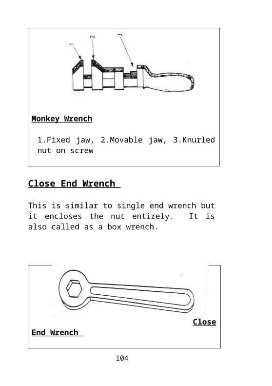
Monkey Wrench
The jaw of this wrench open parallel and can be moved using a screw and hence can be adjusted to a range of openings. The jaws being flat, do not damage the sides of the nut.
Monkey Wrench
1.Fixed jaw, 2.Movable jaw, 3.Knurled nut on screw
Close End Wrench
This is similar to single end wrench but it encloses the nut entirely. It is also called as a box wrench.
Close End Wrench
78
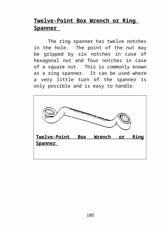
Twelve-Point Box Wrench or Ring Spanner
The ring spanner has twelve notches in the hole. The point of the nut may be gripped by six notches in case of hexagonal nut and four notches in case of a square nut. This is commonly known as a ring spanner. It can be used where a very little turn of the spanner is only possible and is easy to handle.
Twelve-Point Box Wrench or Ring Spanner
79
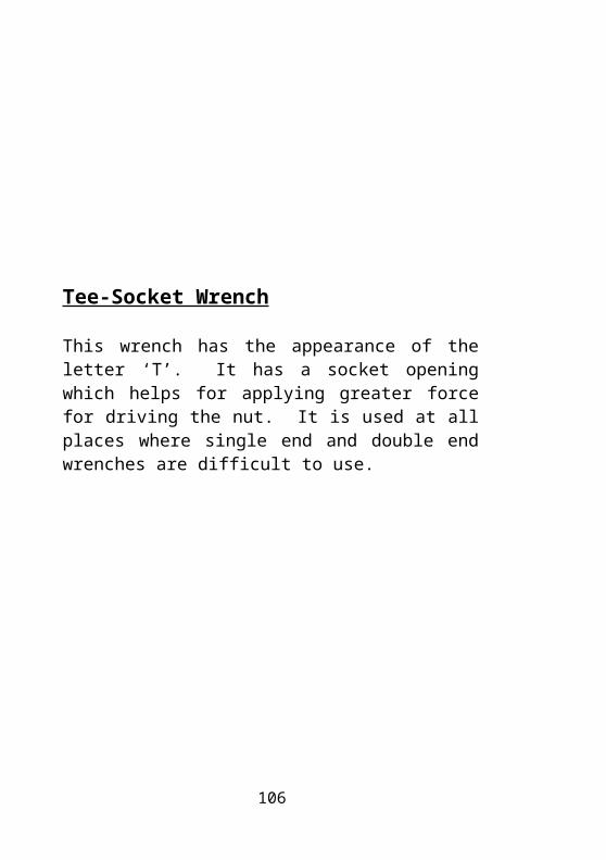
Tee-Socket Wrench
This wrench has the appearance of the letter ‘T’. It has a socket opening which helps for applying greater force for driving the nut. It is used at all places where single end and double end wrenches are difficult to use.
Tee-Socket Wrench
1.Handle, 2.Shank, 3.Head
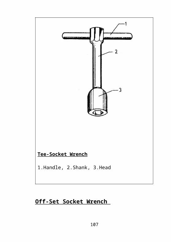
Off-Set Socket Wrench 80
This is similar to a ‘T’ socket wrench but is used for light duty work.
Off-Set Socket Wrench
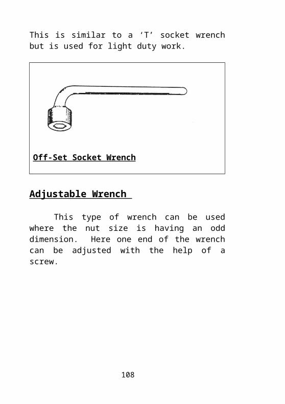
Adjustable Wrench
This type of wrench can be used where the nut size is having an odd dimension. Here one end of the wrench can be adjusted with the help of a screw.
1. Knurled nut on screw
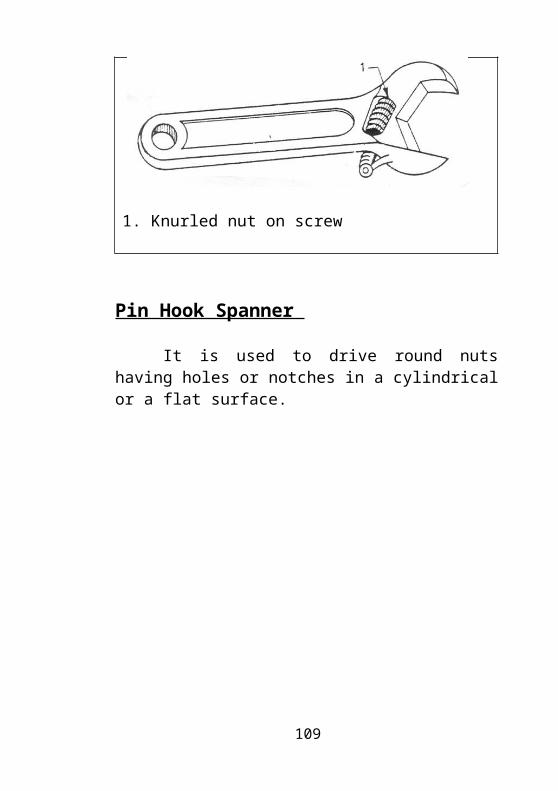
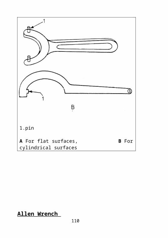
Pin Hook Spanner
81

It is used to drive round nuts having holes or notches in a cylindrical or a flat surface.
1.pin
A For flat surfaces, B For cylindrical surfaces
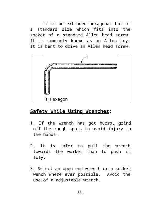
Allen Wrench 82
It is an extruded hexagonal bar of a standard size which fits into the socket of a standard Allen head screw. It is commonly known as an Allen key. It is bent to drive an Allen head screw.
1.Hexagon Safety While Using Wrenches:
1. If the wrench has got burrs, grind off the rough spots to avoid injury to the hands.
2. It is safer to pull the wrench towards the worker than to push it away.
3. Select an open end wrench or a socket wench where ever possible. Avoid the use of a adjustable wrench.
4. To get an extra force, never strike the wrench with a hammer. Use a mallet or a soft hammer if needed.
5. When the nut is not coming out due to rusting, etc with a normal pull, give sudden but controlled jerks.
Assignment:83
1. From what material are the wrenches made up of? What is the purpose of using a wrench?
2. How are spanners specified?
3. What are the types of wrenches, explain briefly each with a neat sketch?
10. PLIERS84
A Plier is a hand tool for gripping or holding of small work pieces. It is also used for cutting of thin sheets, wires etc.
The following are the most common types of pliers in use.
1. Flat plier2. Combination plier3. Cutting plier4. Nose plier5. Poly grip plier
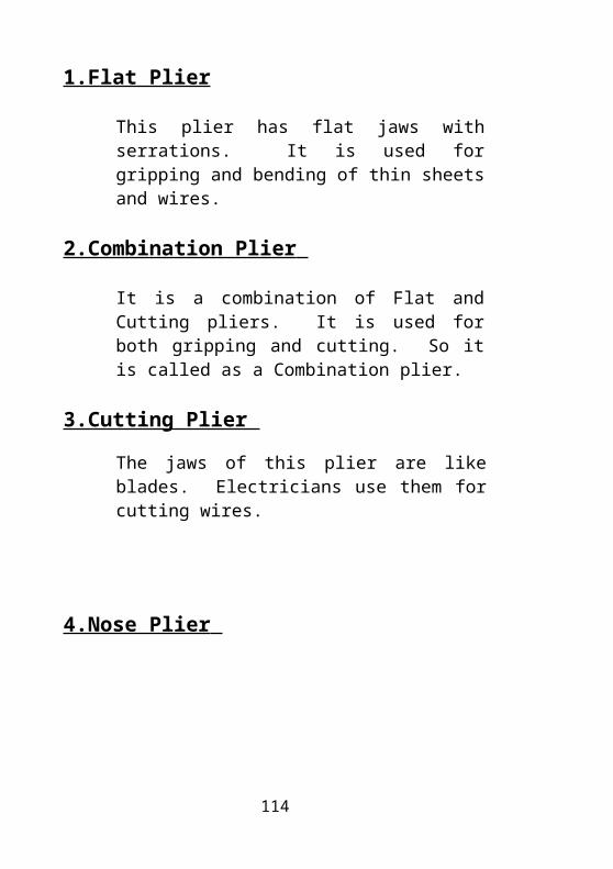
1.Flat Plier
This plier has flat jaws with serrations. It is used for gripping and bending of thin sheets and wires.
2.Combination Plier
It is a combination of Flat and Cutting pliers. It is used for both gripping and cutting. So it is called as a Combination plier.
3.Cutting Plier
The jaws of this plier are like blades. Electricians use them for cutting wires.
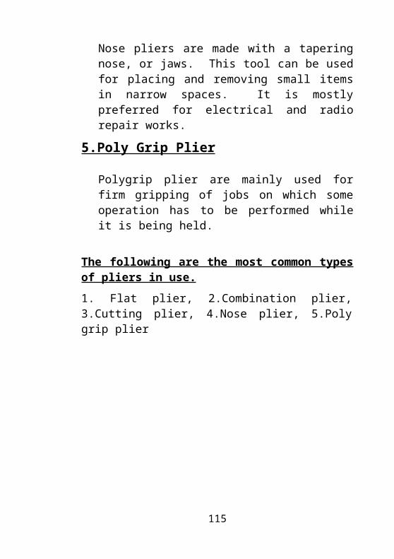
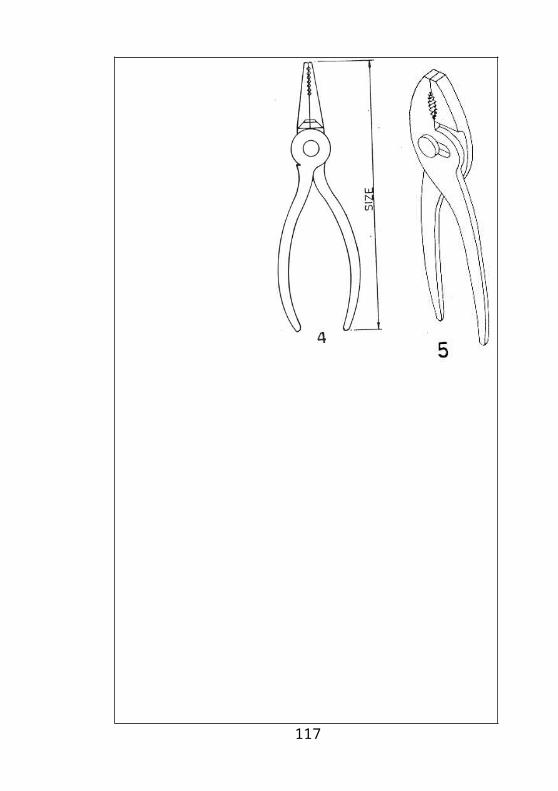
4.Nose Plier
85
Nose pliers are made with a tapering nose, or jaws. This tool can be used for placing and removing small items in narrow spaces. It is mostly preferred for electrical and radio repair works.
5.Poly Grip Plier
Polygrip plier are mainly used for firm gripping of jobs on which some operation has to be performed while it is being held.
The following are the most common types of pliers in use.
1. Flat plier, 2.Combination plier, 3.Cutting plier, 4.Nose plier, 5.Poly grip plier
1.Flat plier 2.Combination plier
86
3.Cutting plier 4.Nose plier 5.Poly grip plier
87
Safety While Using Pliers :
1. The correct types of plier should be used for the correct job.
2. Never use diagonal pliers for cutting steel sheets as this may destroy the cutting edges and damage the tool’s joints.
3. Never use the plier as a hammer.
4. Make sure that proper insulation material is wound round the handle of a plier used for electrical purposes.
Assignment:
1. What are the uses of pliers?
2. Mention different types of pliers?
3. Explain in brief types of pliers with a neat sketch?
4. Mention different safety while using pliers?
88
11. DRILLS
Drilling is an operation of producing a hole in a solid material by means of a cutting tool called as a drill. Twist drills and flat drills are commonly used for producing holes. Drills are normally made of High Speed Steel.Tungsten carbide drills are also available.
Types Of Drills:
The following are three main types of drills:
A. Flat drill
B.Straight fluted drill
C.Twist drill
The other types of drills are
1. Carbide tip drills
2. Counter sink drills
3. Counter bore drills
4.3 or 4 fluted drills
5. Long series drills
6. Oil hole drills
7. Stub series drills
8. Subland or step drills
89
A. Flat Drill :
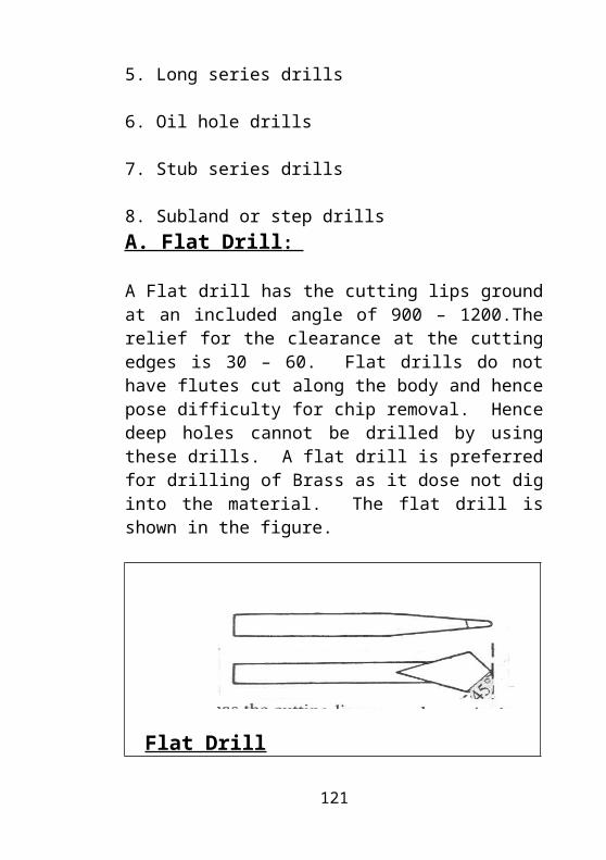
A Flat drill has the cutting lips ground at an included angle of 900 – 1200.The relief for the clearance at the cutting edges is 30 – 60. Flat drills do not have flutes cut along the body and hence pose difficulty for chip removal. Hence deep holes cannot be drilled by using these drills. A flat drill is preferred for drilling of Brass as it dose not dig into the material. The flat drill is shown in the figure.
Flat Drill
B.Straight Fluted Drill:
A straight fluted drill is a drill having its flutes running parallel to its axis. A straight fluted drill has a Zero rake. Chip removal is affected due to the straight nature of the flutes. The drill has to be often removed for clearing the chips during drilling. In drilling of soft materials like Brass, the drill tends to advance faster than the rate of feed and the drill digs into the material. Such problems are not encounted when using a Straight fluted drill. When drilling sheet metal, the straight fluted drill does not tend to lift the sheet from the table as in the case of a twist drill.
90
Straight Fluted Drill
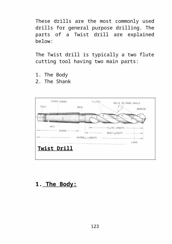
C.Twist Drill
These drills are the most commonly used drills for general purpose drilling. The parts of a Twist drill are explained below:
The Twist drill is typically a two flute cutting tool having two main parts:
1. The Body2. The Shank
Twist Drill
91
1. The Body:
The body consists of the cutting point and the cylinder and with two opposite helical grooves, or flutes. The flutes have a special profile forming the cutting edges and providing the necessary space for the flow of chips, which come up along the flutes from the hole being drilled. Two narrow margins running along the flutes on the cylinder of the body guide the drill in the hole and reduces its friction against the hole surface. The body consists of the following parts:
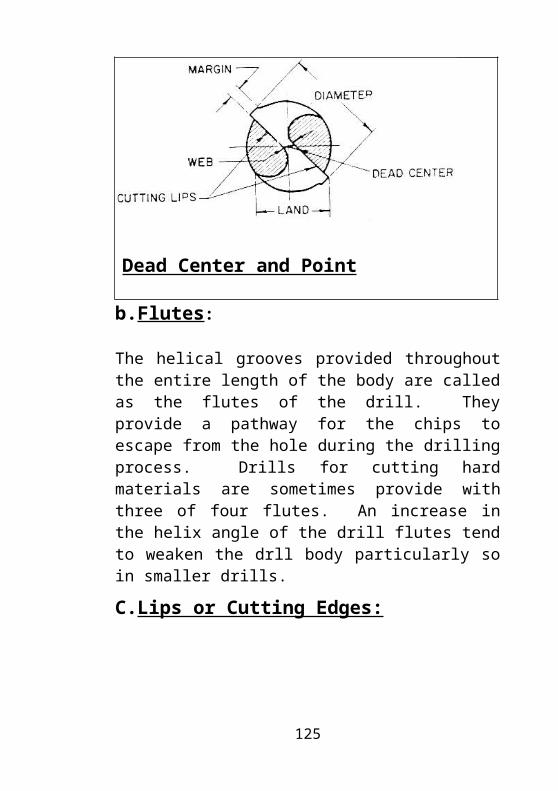
a. Dead Center and Point
The point is the conical portion at one end of the drill opposite to the shank. Normally this point is ground at 1180 with each cutting lip or edge shaped at an angle of 590 with the axis af the drill. The point tapers down to a sharp edge and is the extreme point of the drill. This is called as the Dead center of the drill. The dead center is usually 1/3rd the diameter of the drill. The dead center should always lie in the exact center of the drill axis.
Dead Center and Point
92
b.Flutes:
The helical grooves provided throughout the entire length of the body are called as the flutes of the drill. They provide a pathway for the chips to escape from the hole during the drilling process. Drills for cutting hard materials are sometimes provide with three of four flutes. An increase in the helix angle of the drill flutes tend to weaken the drll body particularly so in smaller drills.
C.Lips or Cutting Edges:
It is that part which acutally cuts the material when drilling a hole. Lips are formed by the intersection of the flutes and the point. The length of the lips should be ground always equal, as otherwise only one lip will take the cutcausing a rough hole and damage to the drill.
93
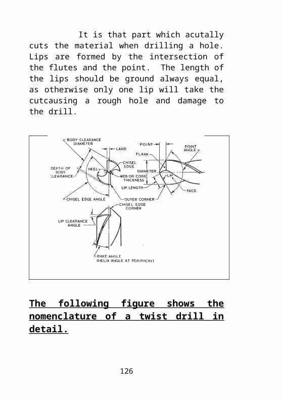
The following figure shows the nomenclature of a twist drill in detail.
A lip clearance is often provided on the lips. Lip clearance is that surface of the point that is ground away or relieved just back of the cutting lip of the drill. The lip clearance allows the drill to enter the metal with less friction and resistance.
Nomenclature of a twist drill in detail.
a. Body Clearance:The portion of the land that has been cut away so that it does not rub the walls of the hole being drilled is called as the Body clearance.
b.Margin or Land:
The margin is the narrow strip shown in Fig. 53 and Fig. 54. It ensures the finish Diameter of the drill and extends along the ensure length of the flute.
94
c.Web:
Web is the central portions of the drill body that owns the lands of the drill. It runs throughout the length of the flutes. The web is thicker at the ends than at the point to give enough strength to the drill.
2.Shank:
Most taper shank drills are provided with a groove like neck between the shank and the body. The neck is utilized for stamping the size, material of the drill and the manufacturer’s name or trade mark. There are three types of shanks in common use. They are straight, taper and square shanks. The drill is held at the shank and rotated. Taper shanks, generally in Morse tapers are made in drills from 6 to 80mm in diameter and Straight shanks in those upto 20mm in diameter. Taper shank drills are placed directly into the bore of the drilling machine spindle of through taper sleeves and held in the spindle by a drill chuck.
95
The other types of drills:
1. Carbide tip drills, 2.Counter sink drills, 3.Counter bore drills,4.3 or 4 fluted drills, 5.Long series drills, 6.Oil hole drills,7.Stub series drills, 8.Subland or step drills
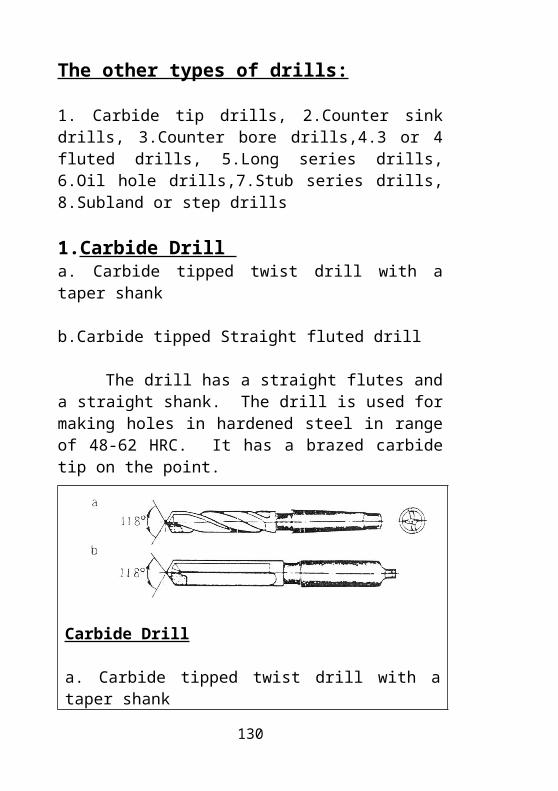
1.Carbide Drill a. Carbide tipped twist drill with a taper shank
b.Carbide tipped Straight fluted drill
The drill has a straight flutes and a straight shank. The drill is used for making holes in hardened steel in range of 48-62 HRC. It has a brazed carbide tip on the point.
Carbide Drill
a. Carbide tipped twist drill with a taper shankb.Carbide tipped Straight fluted drill
96
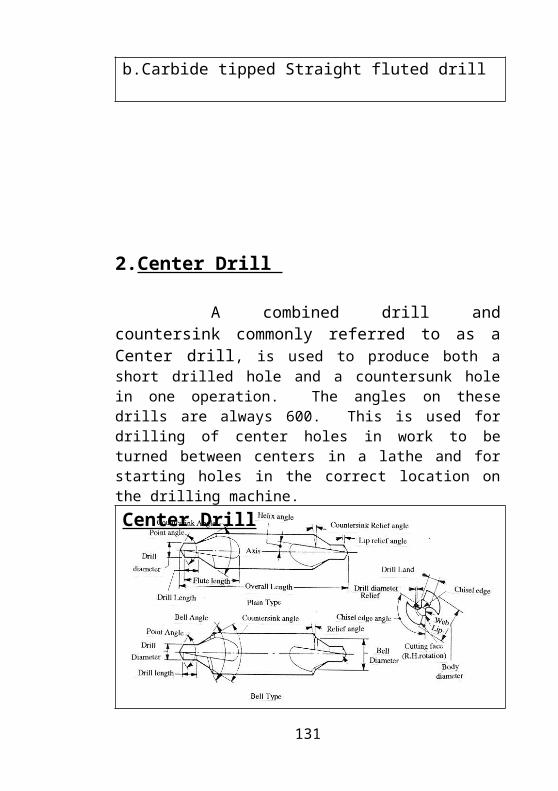
2.Center Drill
A combined drill and countersink commonly referred to as a Center drill, is used to produce both a short drilled hole and a countersunk hole in one operation. The angles on these drills are always 600. This is used for drilling of center holes in work to be turned between centers in a lathe and for starting holes in the correct location on the drilling machine.
Center Drill
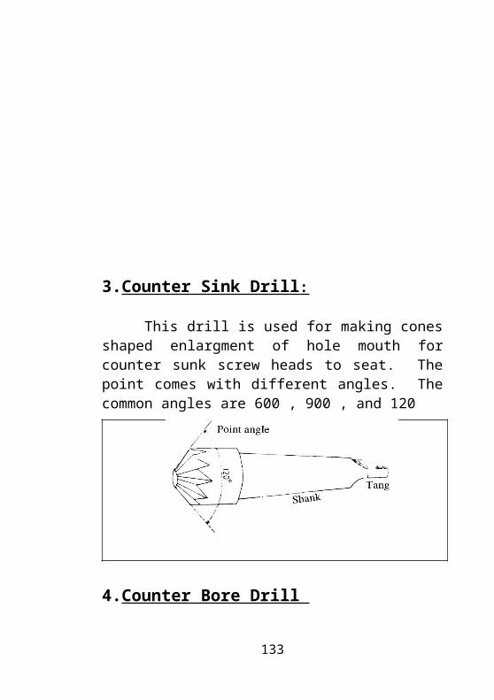
3.Counter Sink Drill :
97
This drill is used for making cones shaped enlargment of hole mouth for counter sunk screw heads to seat. The point comes with different angles. The common angles are 600 , 900 , and 120
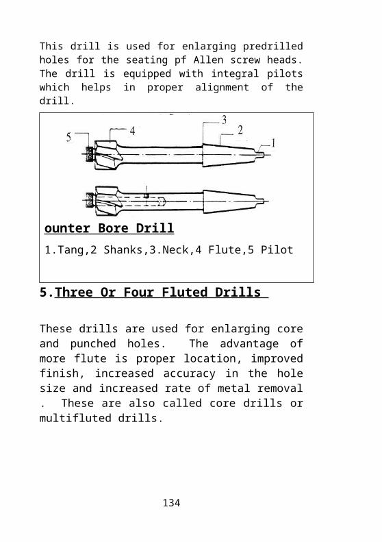
4.Counter Bore Drill
This drill is used for enlarging predrilled holes for the seating pf Allen screw heads. The drill is equipped with integral pilots which helps in proper alignment of the drill.
ounter Bore Drill
1.Tang,2 Shanks,3.Neck,4 Flute,5 Pilot
5.Three Or Four Fluted Drills
98

These drills are used for enlarging core and punched holes. The advantage of more flute is proper location, improved finish, increased accuracy in the hole size and increased rate of metal removal . These are also called core drills or multifluted drills.
Three Or Four Fluted Drill
1. Tang, 2. Shank, 3. Neck, 4. Lip
6. Long Series Twist DrillThe fluted part of this drill is more than the length of a
twist drill. This drill is used for drilling deep holes. This drill comes in straight shanks only.
Long Series Twist Drill
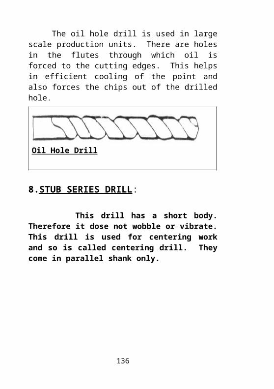
7.Oil Hole Drill
99
The oil hole drill is used in large scale production units. There are holes in the flutes through which oil is forced to the cutting edges. This helps in efficient cooling of the point and also forces the chips out of the drilled hole.
Oil Hole Drill
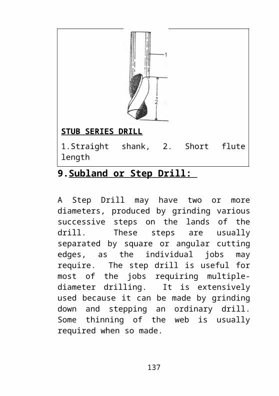
8.STUB SERIES DRILL:
This drill has a short body. Therefore it dose not wobble or vibrate. This drill is used for centering work and so is called centering drill. They come in parallel shank only.
STUB SERIES DRILL
1.Straight shank, 2. Short flute length
9.Subland or Step Drill:
100
A Step Drill may have two or more diameters, produced by grinding various successive steps on the lands of the drill. These steps are usually separated by square or angular cutting edges, as the individual jobs may require. The step drill is useful for most of the jobs requiring multiple-diameter drilling. It is extensively used because it can be made by grinding down and stepping an ordinary drill. Some thinning of the web is usually required when so made.
Sub land drills; perform the same function as the step drill, while its construction is somewhat different. The step drill has its steps or different diameters on the same land, while the Sub land drill has two distinct lands running substantially to the entire length of the flutes. This is shown in the figure.
12. DRILLING MACHINES:
101
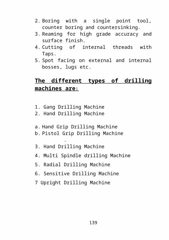
A Drilling machine is one in which the following operations can be performed:
1. Drilling of through or blind holes.2. Boring with a single point tool, counter boring and
countersinking.3. Reaming for high grade accuracy and surface
finish.4. Cutting of internal threads with Taps.5. Spot facing on external and internal bosses, lugs
etc.
The different types of drilling machines are :
1. Gang Drilling Machine2. Hand Drilling Machine
a. Hand Grip Drilling Machineb. Pistol Grip Drilling Machine
.3. Hand Drilling Machine
4. Multi Spindle drilling Machine
5. Radial Drilling Machine
6. Sensitive Drilling Machine
7 Upright Drilling Machine
1. GANG DRILLING MACHINE
102
A number of drilling machine heads along with the pillars are mounted on the same table. This machine is used for large scale production work where different sizes are done on the same job. It is done without removing the job from the table. Such machines are called Gang Drilling Machines.
Gang-type, six spindle drilling machine with both hand and power-feed.
2. Hand Drilling Machine
This machine is held manually there are two types of hand drilling machine.
103
1. Pistol Grip drilling machine2. Heavy Grip drilling machine
1. PISTOL GRIP DRILLING MACHINE:
They are used for drilling holes less than diameter 6mm.
2. HEAVY GRIP DRILLING MACHINE:
They are used for drilling holes between diameter 6mm-diameter 13mm. The pistol grip drilling machine is held in one hand and this machine has a finger press retaining button switch, while heavy duty hand grip drilling machines are held in two hands.
The common types of hand drilling machines
104
The common types of hand drilling machines
A. Hand drilling machine – Light duty,
B.Hand drilling machine - Heavy duty
C.Hand drilling machine – Manually operated
1. Switch, 2.Handle, 3.Drill-Cable, 4.Air-holes,5. Motor,, 6,Knurledgrip,7.Chuck,8.Drill,9.Handle,10. Hand wheel, 11. Body, 12. Bevel gear wheel,13. Chuck mounting threads, 14. Chuck, 15.Drill
4. Multi Spindle Machine
105
This machine has number of spindles run by a motor mounted on it. This drilling machine is used when a number of holes of the same size or of different sizes are to be drilled on the same surface.
Multi Spindle Machine
5. Radial Drilling Machine
106
This machine is used for working on heavy and large components. The arm of the machine is capable of moving in the radius of its column. This machine has the following special features.
1. High capacities of drill large holes
2. Large clamping surface and a wide range of heights between spindle and base.
3. A wide range of spindle feeds which enables to drill large and small holes as well as to perform reaming and tapping.
4. Mostly the elevation of the arm is carried with the help of motor.
5. Ample rigidity which avoids vibration. A few radial drill machines have universal head movements.
6. Sensitive Drilling Machine
107
A Sensitive Drilling Machine is a belt driven general purpose drilling machine used to produce a range of small holes. These drilling machines are made in the Floor model, Bench model and Multiple spindle models. It is called as a sensitive drilling machine because of its accurately balanced spindle.
Sensitive Drilling Machine
7. Upright Drilling Machine
108
This is a heavy structured machine and therefore larger sized holes than that are possible on a sensitive drilling machine are drilled on this machine. They are equipped with slower speeds than sensitive drilling machines and the spindle is driven by stepped pulley through “V” belt or a flat belt. This has both manual and automatic feed mechanism.
Upright Drilling Machine
109
Specifications of a Drilling Machine:
1. Column diameter: E.g. 100 mm
2. Capacity-maximum size of drill that can be drilled on the machine, say, 18mm.
3. Capacity swing- The maximum diameter of the job can be held on the machine table while drilling, E.g. 250mm.
4. Distance from the center of the spindle to the center of the column.
5. Feed- whether manually operated or automatic, feed range E.g.0.05-0.18.
6. Height of the machine. E.g.2100mm
7. Maximum vertical traverse of the spindle E.g.150mm
8. Maximum distance from the table to the highest point of the spindle E.g. 218mm
9. Motor capacity E.g. H.P. of motor, R.P.M-1200, A.C. or D.C. and voltage-440v.
10 Speeds-Range of rpm. E.g. 50, 75, 100, 215, 400, 600, 750, 800,1000 rpm.
11. Spindle hole taper- type and number of taper holes. E.g. M.T.3. (Morse Taper 3).
12. Table size. E.g. 300x350mm.
110
13. T-slots in the table.E.g.6 slots x 14H7
14. Type of starter, whether supplied with drill chuck and key are coolant pump.
15. Type-whether Sensitive, Upright, Radial etc.
Drilling Accessories:
The common types of drilling accessories are mentioned below:
1. Drill chuck2. Sleeves3. Drill drift
Drill Chuck: :
The drill chuck is the most common accessory used in drilling machines for holding of mostly drills and reamers with straight shanks. These chucks come in two varieties, The keyless chuck and the keyed chuck. Both these types are illustrated in the
111
Three jaw self centering keyless drill chuck
a.Constructi on b. Setting
1.Shank,2.Sleeve,3.Spring,4. Jaws, 5. Body
Three jaw self centering Key type drill chuck
112
Three jaw self centering Key type drill chuck
1.Jawnut, 2.Sleeve,3.Key hole,4.Key
113
Sleeves
According to the type of shank, Twist drills, Reamer, Counterbores,etc.are held in the drilling machine spindle by three methods. Directly in the taper bore of the spindle, in Taper sleeves and in the drill chucks. The placement of the drill in the
Spindle bore directly is shown in the fig.72. Morse taper is the most commonly used taper in the drilling machine spindle. Morse tapers are designated in numbers 0-6.
Taper sleeves are used when the taper diameter of the drill or reamer is less than the bore diameter of the machine spindle. The sleeve with the drill is inserted into the spindle bore and held there by the self locking Morse taper. This is illustrated in the Fig.72.Sleeves are available in sets according to the increase in the taper bore diameter.
a. Directly In spindle hole taper Tool holding methodsb. set of taper sleevec.Setting a drill in a sleeve
a.Directly In spindle hole taper Tool holding methods114
b. set of taper sleeve, c.Setting a drill in a sleeve
Drill Drifts:
The drill drift is an accessory on the drilling machine used to remove the taper shank drills or sleeves from the spindle. The drill drift is introduced into the slot provided in the spindle and a light tap is given to push out the drill or sleeve thus releasing the self locking. shows the drill drift in use.
Usage of drifts to remove a tool from the spindle
115

Usage of drifts to remove a tool from the spindle
a. Using plane Drift b. Using a Safety drift
116
Trouble Shooting In Drilling:
SYMPTOMS PROBABLE-CAUSES
REMEDIES
1. Breaking of the drill.
1.Blunt drill
2.Less clearance3.Less cutting speed4.Chip blocking in the flutes
1.Resharpen the drill 2.Provide proper clearance3. Use correct speed.4. Lift the drill more
often during work.
2. Burning marks in the cutting edge.
1.Dry drilling 2.Higher feed rate.
1.use coolant 2. Use optimum feeds.
3. Drill refuses to enter work.
1. Dull drill.
2.Too little lip clearance.
1.Sharpen the drill 2. Provide.proper.lip.
clearance
4. Hole larger than the drill size.
1. Unequal lip length.
1. Grind the lip length equally.
Safety While Drilling:117
1. clean the machine spindle thoroughly before mounting the drill chuck to ensure proper seating.
2. Clamp the job rigidly to the vice or table before starting to drill.
3. Do not leave the drift in the machine spindle after removing the sleeve or drill chuck.
4. Do not force the drill into the work. Use optimum cutting speeds and feeds.
5. Do not change gears while the machine is in the running condition.
6. Never try to hold the work in hand.
7. Never remove the clips by hand. Always use a brush for cleaning the chips.
8. Use a proper coolant while drilling, otherwise the hot chips may cause injury.
Assignment:
118
1. What is drilling?
2. Mention different types of drills?
3, Write notes on i) Flat drill.ii)Straight fluted drilliii)Twist drill with a neat sketch?
4. Briefly explain the body of the drill?
5. Mention the different parts of the body of the drill?
6. Briefly explain the dead center and point in the body of the drill with a neat sketch?
7. Write notes on i)Flutes ii) Lips or cutting edgesIii) Body clearanceiv) Margin or landVI) Web.
8. Write a note on shank of the drill?
9. Write a note on carbide drill, center drill, counter sink drill, center bore drill with a neat sketch?
10. Write a note on, three or four fluted drills, long series twist drills, oil hole drills, stub series drills with a neat sketch?
11. Write a brief note on sub land or step drill with a neat sketch?
119
12. What are the different operations that can be performed in a drilling machine?
13. What are the different types of drilling machines?14. Explain gang and hand drilling machines?
15. Explain with a neat sketch with sensitive drilling machine?
16. How are drilling machines specified?
17. Mention the different drilling accessories and explain?
18. Mention some safety while drilling?
19. Mention some symptoms, probable causes and remedies in drilling?
13. REAMERS120
A reamer is a rotary cutting tool, generally of cylindrical or conical shape, intended for enlarging and finishing holes to accurate dimensions. It is usually equipped with two or more peripheral channels or flutes either parallel to its axis or in a right hand or left-hand helix as required. The reamers having helical flutes are subject to less chatter, provide a smoother cutting action and produce a better finish. The flutes form the cutting teeth and provide a pathway for removing the chips.
Parts Of A Reamer
A Reamer consists of the following main parts:
1. Cutting edge2. Flutes3. Land 4. Shank5. Tang
Cutting Edge:
The edge formed by the meeting of the flank and the face is called as the cutting edge.
Flutes:
The longitudinal channels formed in the body of the reamer to provide cutting edges, permit the passage of chips and allow the cutting fluid to reach the cutting edges are called as the flutes.
Land:
The section of the reamer between the adjacent flutes i.e., the black portion of the cutting edge is called as the land.
121

Shank:
Shank is the portion of the reamer by which it is held and driven.
Tang:
Tang is the flattened end of the tapered shank that fits a slot in the sleeve or machine spindle.
Type Of Reamers:
Reamers are grouped into two categories.
1. Hand reamers2. Machine reamers.
1.Hand Reamers
122
These are finishing tools used when a hole must be finished to a high degree of accuracy and finish. A square shank allows the wrench to be used for rotating the reamer in the hole. The teeth on one end of the reamer are tapered slightly for a certain distance, so that it can enter the hole and act as a guide whereas in machine reamers this taper is absent, but a chamfer at the tip is provided for easy entry. Hand reamers should never be turned back wards while reaming as this may damage the cutting edges. Both roughing and finishing tapered hand reamers are available for all standard sizes. Since the chip does not fall readily, tapered hand reamers should be removed from the hole and the flute should be cleaned frequently.
2. Machine Reamers or Chucking Reamers
These reamers may be used in drilling and milling machines for both roughing and finishing of holes. Machine reamers normally have taper shanks, but straight shank reamers are also available. They are also called as chucking reamers because of the method used to hold them. Machine reamers are available in a wide variety of types. Some of the types are straight shank helical flute reamer, expansion reamer, rose reamer, stub screw machine reamer, jobber reamer, taper finishing reamer, taper shank bridge reamer, die makers reamers with high spiral flutes, taper shank combination drill and reamer etc. these reamers are illustrated in the figure.
Hand Reamers and Machine Reamers.
123
Machine Reamers or Chucking Reamers.
124
Speeds for Reaming:
125
The speed or R.P.M. for reaming is normally 1/3 rd the speed used for drilling.
Safety While Reaming :
1. Always store reamer in separate boxes or containers to prevent the cutting edges from nicking and burning.
2. Cutting fluids should be used while reaming to improve hole finish.
3. Do not turn the reamer backwards while taking it out of the hole for cleaning the chips. This may damage the cutting edges
.4. Do not use a hand reamer as a machine reamer
and vice-versa.
5. Never rotate the reamer backwards. This will damage the cutting edge.
6. Never roll or drop the reamer on a metal surface.7. When it is not in use keep it oiled to prevent it from
rusting.
14. MARKING AND LAYOUT TOOLS:
126

The following are the common types of marking and layout tools in a workshop that is of relevance to a toolmaker.
1. Calipers and Dividers.2. Punches.3. Surface plates.4. Scribers.5. Try squares.
1. Calipers and Dividers :
Dividers are used to markout circles, arcs for dividing straight and curvilinear lines and for plotting geometrical figures. They are also used to transfer dimensions from the rulers to the work pieces. Calipers are used as checking instruments and to measure the inside and outside diameters of workpieces generally. These instruments are finding less usage in the present days. The different types of calipers are shown in the figure below.
Calipers and Dividers.
127
128
Calipers and Dividers
129
2. Punches:
As the name suggests these are used for punching on marked lines, hole centers, boundaries etc. Punches are classified into three types depending on the included angle of the point.
1. Prick punch (300). 2. Dot punch (600)3. Center punch (900)
Prick punches are used to make small indent marks on layout lines. The dot punch is used to enlarge the mark made by the prick punch and enable it to last longer. Center punches further enlarge the mark made by the dot punches and are used to guide the drill bits. Fig. 78 shows the three different types of punches.
130
1.Head, 2.Knurled length of body3. Surface Plate:
The surface plate is usually a Seasoned Cast iron block, which is scraped to a high degree of accuracy and flatness. The surface plate is mainly used for marking purposes. Angle plates, Vernier height gauges etc. are used on the surface plate for marking purposes. Surface plate are also made of granite are hardened steel. The fig shows a surface plate.
131

Surface Plate
132
4. Scribers:
Scribers are used for marking lines on work surfaces with the aid of steel rules, squares and templates. Scribers are made of Tool steel. To layout on well-finished sheet surfaces, scribers made of brass are usually used. Scribers come in three main varieties. Single point, double point and removable point type. The single point scriber is a steel rod of 150 to 250mm in length and 4 – 5mm in diameter. One end is hardened to a length of 20 – 30mm from the tip and sharpened at an angle of 150. The other end bent to form an eye 25 – 30mm in diameter. The double point scriber is a steel rod with both the ends pointed; one point is bent at right angles to the shank. The shank is greater in diameter and knurled to provide a better grip. The bent end is used in reaching through holes etc. The scriber with removable point is similar to a watchmaker’s screwdriver; the point is a ground and a sharpened steel rod. The Fig. indicates the above mentioned scribers.
133
Scribers.
Scribers
134

5. Try Squares:
Try squares are precision tools made of stabilized hardened steel, which are normally made of two pieces and riveted to each other. Perfect right angle is maintained between the Beam and the Blade. The try square is mainly used for checking the right angles of machined jobs and also for setting jobs on the machine. The blade is thinner than the beam and is lengthier than the beam. Try squares are of the following types:
1. Fixed try square.
2. Adjustable try square.3. Bevel edge try square. 4. Tool and die makers square.Fixed try square
Fixed try squares, as the name suggests, have the blade and the beam fixed to each other by means of rivets. Adjustable try squares have an adjusting screw by which the length of the blade can be varied forward or backwards depending as per requirements. Bevel edge try squares have their edges beveled at 450 and as such provide an improved perfect line contact with the job. Tool and die maker’s try squares are mostly used by toolmakers. They have detachable blades and are useful for measuring small angles and slots on inserts and precision job surfaces. The four types of try squares mentioned above are shown in fig
135
Try Squares:
Try Squares
A. Ordinary Engineers Try square,B. Precision Bevelled edge Try squareC. Precision Try square with a light D. Adjustable Try squareE. Adj. Try square with a pair of blades used by die
makers to check small1.Blade,2.Notch, 3.Stock
136
15. TAPS AND DIES
Thread :
A screw thread is a ridge of uniform section in the form of a Helix cut around the circumference of a cylinder and advancing along the axis. The different types of threads and their terminologies are discussed in the next chapter. Taps and dies are used to produce threads.
1. Taps
A tap is a cylindrical bar of steel with threads formed around it and grooves or flutes running lengthwise on it, intersecting with the threads to form the cutting edges. It is used to cut internal threads. Fig.82 shows the principal parts of a tap used to cut Metric threads. Tapping is the operation of producing threads in a material.
Taps and dies are extensively used to produce internal and external threads.
Taps
Taps
Parts of a Tap:137

Cutting Face:
The front part of the thread portion is the cutting face. The chip strikes on it while threading. Flutes:
The longitudinal channels formed in a Tap to create the cutting edges on the thread profile and to provide chip space and cutting fluid passages are called as the flutes. On parallel or straight thread taps, the flutes may be straight, angular, or helical; on a taper thread tap, they may be straight, angular or spiral.
Heel:
It is the back portion of the thread on the land.
Land:
One of the threaded sections between the flutes of the tap is called as the Land.
Shank:
The uncut cylindrical portion behind the cutting length of the body is called as the shank. The top portion of the shank has the tang.
Tang:
138
The Tang is the topmost portion of the tap shank used for driving the tap. The tang portion of the tap fits into the Tap wrench. Hand taps have square tangs provided on them. Machine taps have a shank similar to that of a Taper shank drill.
Thread Relief
Like all cutting tools, the tap thread is backed off to give relief to the cutting edge. This allows the tap to penetrate into the metal easily.
Kinds of Taps
There are two common types of taps in use. They are hand taps and Machine taps. Hand Taps:
As the name suggests these taps are used to produce threads manually using a tap wrench. These are taps with the thread and the shank approximately of the same length, and a square tang to accommodate a driving mechanism. Hand taps usually come in a set of three. They are called as Taper, Plug and Bottoming taps. They are also called as 1st, 2nd and 3rd taps. The 1st tap or taper tap has about 1/3rd the end of the portion tapered. This enables the tap to enter in the hole and cut the starting threads. The 2nd tap tapers upto three to four teeth and the 3rd tap has a one thread taper. All the three taps are necessary to cut the threads to get good finished threads.
139
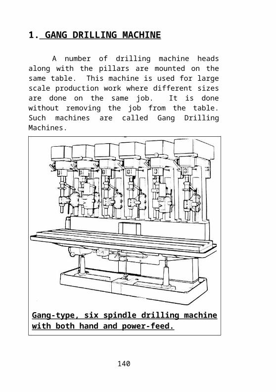
Hand Taps
Hand Taps
Machine Taps
140
Machine screw taps are small taps, usually lesser
than 6mm in diameter. They are usually manufactured in sets of two. Taper and bottoming taps. They are available as Two flutes or Three flute tapsMachine Taps
Material of the Taps:
High Speed Steel (H.S.S) is mainly used for manufacturing taps. Also, High Carbon High Chromium Steel containing 1.45 – 1.7% of carbon, 0.2 – 0.4% manganese and 11 – 12.5% chromium is used. The hardness of High Speed Steel taps should be 60 – 63 H.R.C, while for High Carbon High Chromium Steel H.R.C should be 62 – 65 H.R.C.
141
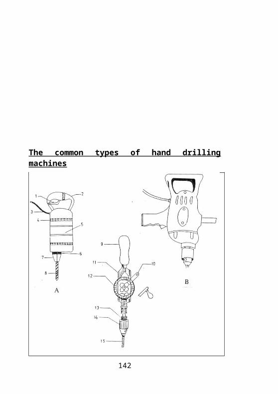
Tap Wrenches :
Tap wrenches are devices used to hold and drive the hand taps while tapping. Tap wrenches are usually made from Mild steel. The following types are commonly used.
Tap Wrenches
a.Tap wrench fixed (small types),b.Tap wrench adjustable
Dies:
A die is metal piece usually made of High Speed Steel that has internal threads in it. It is used for cutting external threads on a cylindrical work piece. Dies are of many types. The most common types in use are Solid dies and Split dies.
142

Solid Dies
A solid die is High Speed Steel hardened nut having axial clearance holes that from the cutting edges and accommodate the chip removed. Chamfer 3 with a length of 1.5 – 2 threads are provided in a threaded portion 2 on both sides such dies are used for cutting threads upto 52mm in diameter in a single pass.
Split Dies
Flexible dies, as distinct from solid dies, have a slit (0.5mm – 1.5mm) which allows the diameter of the thread to be adjusted within the range of 0.1 – 0.25mm. When hand operated, the split are solid dies are held in a Diestock. The commonly used dies are of Round cross section although rectangular dies are also available.
Die Stock:
Die stock is device used to encase, hold and drive the die while cutting threads. It is normally made of Mild steel and has a screw to tighten the seating position of the die in the die stock. Fig. 88 shows the die stock being used to cut threads and its parts.
143
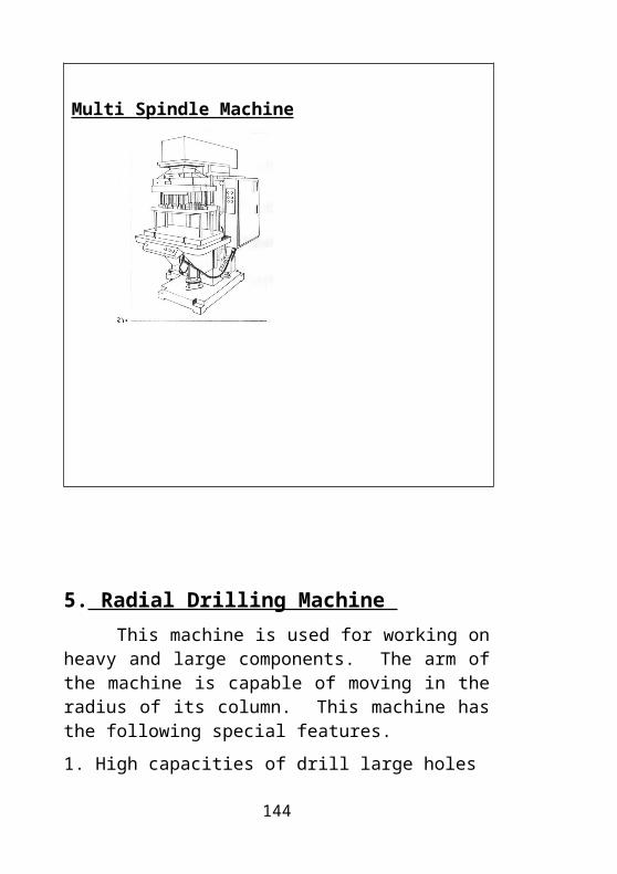
Solid Dies Die Stock Split Dies
Safety while using Taps and Dies :
1. Always chamfer the hole to be threaded. This helps the Tap or the Die to start easily.
2. Do not exert too much force while cutting threads, as this may cause the die or the tap to break.
3. Ensure that the correct size of core drill has been drilled, as an undersized hole may make tapping difficult and result in breakage due to forcing.
144
4. Fix the job to be threaded securely in the work holding device.
5. Use the correct size Tap wrenches as an unnecessarily long leverage for a small tap might cause its breakage.
6.Use proper cutting fluids while cutting threads as this helps in lubrication and easy chip clearance.
7. While tapping blind holes, take care to clear the chips often.
16.THREADS AND THREADING
Thread:
A thread may be defined as a ridge of uniform section in the form of a Helix cut around the circumference of a cylinder and advancing along the axis.
145

Threading:
Threading is the operation of producing threads in work pieces.
Parts of a Screw Thread:
There are many types of threads, out of which the Metric thread is the most commonly used. The terms of a Metric screw thread are shown in Fig. 89 and explained below. The terms explained below apply to all types of threads irrespective of the thread form.
Angle Of The Thread:
The angle included between the sides of the thread, measured in an axial plane.
Crest:
The top surface joining the two sides of a thread.
Depth Of Thread:
A single depth of the thread is equal to half of the difference between the Major and Minor diameters of the thread.
Helix Angle: 146
The angle made by the helix of the thread at the pitch diameter, with a plain perpendicular to the axis.
Lead:
The distance advanced by the screw axially in one turn. On a single thread screw, the lead and the pitch are identical; On a double thread screw, the lead is twice the pitch; on a triple thread screw the lead is thrice the pitch and so on.
Major Diameter:
The largest diameter of the thread of the screw or nut.
Minor Diameter:
The smallest diameter of a thread, screw or nut.
Pitch:
The distance from a point on a screw thread to a corresponding point on the next thread measured parallel to the axis.
Pitch Diameter:
On a straight screw thread it is the diameter of an imaginary cylinder, the surface of which would pass through the threads at such points so as to make equal the width of the threads and the width of the spaces cut by the surface of the cylinder.
Root:
147
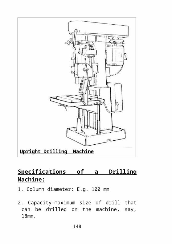
The bottom surface joining the sides of two adjacent threads.
Side or Flank:
The surface between the Crest and the Root.
Nomenclature of Thread;
Nomenclature of Threads
Types or Forms of Threads:
Screw threads are of the following types depending on the cross sectional form they take.1. Metric threads 2. Acme threads.3...Buttress threads.. 4. Pipe threads.5. Round threads or Knuckle threads.6. Square threads
148
1. Metric Threads
:The metric screw thread has an included angle of 600
and is the most commonly used type of thread. These screw threads are designated by the capital letter “M” and “X” sign between the pitch and the diameter. The threads form a sharp “V” profile. For coarse threads pitch is not indicated and standard tables have to be referred. E.g. M10, M12 etc. The crest is recommended to be cleared by a width of P/8. The Fig. shows the cross section of a Metric thread.
Metric Threads
2.Acme Threads:
Acme screw threads have been developed to carry heavy loads without causing excessive radial bursting pressure in the nut. They are also used to produce traversing motion on the machines and tools and is largely used in the Feed screw and the Lead screw of machines. An Acme thread is a modification of the square form of the thread. It is preferred for many jobs, as it is fairly easy to machine. It has a 290
included angle. The thread form and the symbols used are shown in Fig.90.Acme Threads
149
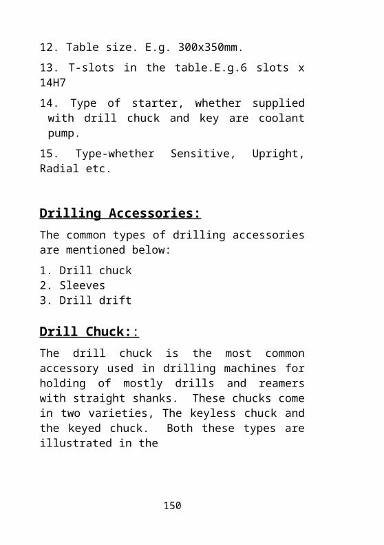
3. Buttress Threads:
A buttress thread is cut square on one side and slanting on the other side to an angle of 450. It is used where a thread requiring great strength in one direction is necessary, as in certain type of vices. In some cases, the load resisting side may be inclined from 10 – 70 to avoid cuts or tool interference in cutting the threads.
150
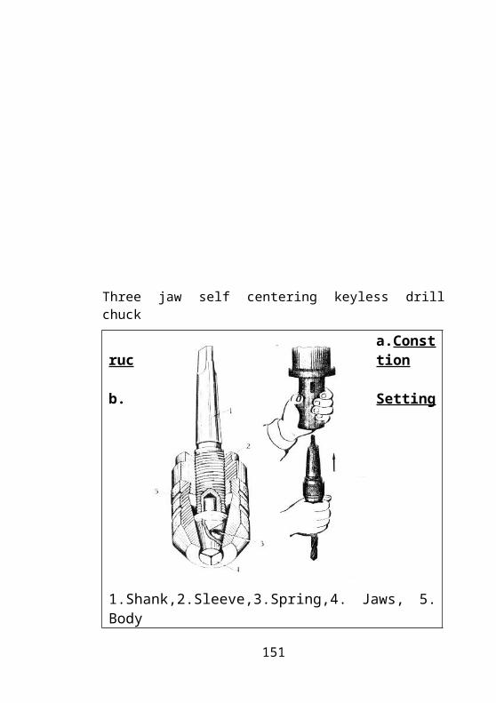
Buttress Threads
4. Pipe Threads :
151

Pipe threads as the name suggests are used in pipes fitting. Among pipe threads the most common in use world wide are the British Standard Pipe threads. They have an included angle of 550 and are tapered 1/16’’ per inch on the diameter. This provides for a tighter fit and reduces the chances of leakage in the pipe.
Pipe Threads
5. Round Threads or Knuckle Threads:
152
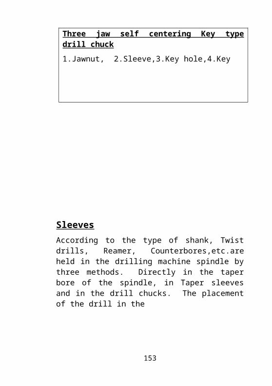
The profile of this thread is yet another modification of the Square thread. The sharp corners of the square threads that are liable for damage are rounded off as shown in Fig. 94. This thread is used where heavy were and rough use is expected as in a Railway carriage coupling screw. The advantage of this thread is that it can be rolled in a sheet metal or cast to have shallow depths that make it useful on electric bulbs and sockets, Bottle tops etc.
The knuckle thread shown in the Fig.94 a is the ISO thread profile adopted by the Bureau of Indian standards in preference to the basic knuckle thread. A knuckle thread is designated by the letter ‘’k’’ followed by the nominal diameter and pitch, the two being separated by the “X” sign. For e.g. a knuckle thread of Nominal diameter 10mm and pitch 2.54mm is designated as K10 x 2.54.
Round Threads or Knuckle Threads
6.Square Threads:
153

Square threads are not in common use owing to the difficulty in manufacturing as the thread is not strong enough as the Acme thread. These are normally used for worm screw forms and some other work holding devices. The sides of the thread are at an angle of 900 to the axis. In this type of thread the width, depth and the space between the threads are equal. A recent version of this is the modified square thread that has an included angle of 100.
Apart from the profiles of threads explained above, threads are of different types depending on whether they are cut internal, external, the number of starts, and turn. They are of the following types.
Square Threads
1. Internal Threads:
154
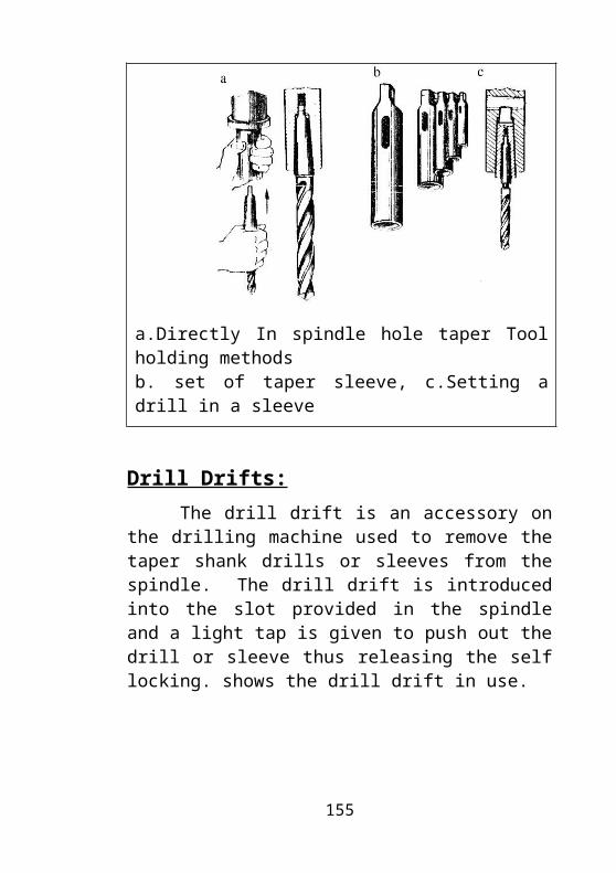
Threads cut inside the job are called Internal threads or female threads.
2.External Threads:
: Threads cut on the circumference of a job are called as External threads or male threads.
3.right- hand helix thread:
A right-handed thread is one which the nut must be turned in the right-hand direction to screw it on.
4.Left- Handed Thread:
A left-hand thread is one in which the nut must be turned in the left- hand direction, to screw it on.
5.Single Start And Multi Start Threads:
: For one complete turn of the screw or bolt, if the advancement is by one thread the screw is termed as a single start thread. For one complete revolution of the screw if the advancement is by more than one thread then the screw is termed as a Multi start thread.
155
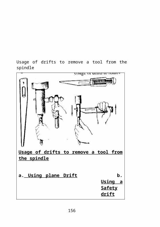
18. MEASURING INSTRUMENTS
Measuring instruments are a part and parcel of any manufacturing process. Discussed below are the measuring instruments used commonly by a Tool maker in the shop floor.
1. Steel Rule:
A steel rule is the simplest and the most commonly used measuring instrument on the shop floor. The steel rule comes in common sizes like one foot or 30cm, and 1meter. The one-foot rule has marking in both inches and Millimeters. It measures 30 inches or 300cms. The minimum measurement possible in mm is 1mm and 1/16th inch in inches. It is used in the shop floor for taking measurements of Raw materials and checking the length or diameters of jobs that have an accuracy of 1mm. Shown below is the sketch of a steel rule.
Steel Rule
156

2. Vernier Caliper
Vernier calipers are measuring instruments that have a Vernier scale incorporated on the movable jaw. The Vernier scale is used for measurement of outside dimensions, inside dimensions, depth of slots, key - ways and steps. The least count of the commonly used Veniers are 0.02 or 0.05mm. There are special types of Vernier calipers for specific uses like inside Vernier caliper, outside Vernier caliper, gear tooth Vernier caliper, dial Vernier, Electronic digital caliper, height gauge etc. The material of the Vernier is a Hardened and stabilized steel.
Parts of a Vernier Caliper:
Beam:
The Beam is that part of the Vernier on which the graduations in mm or inches are marked. The front side of the beam has the main scale divisions marked on it. The Vernier scale slides on the beam. The beam has a channel machined on its backside which aids in the sliding of the depth scale. One end of the beam has a fixed jaw and the other end has a stopper that prevents the Vernier scale from sliding out when the Vernier jaws are opened to its maximum position.
Vernier Scale:
The Vernier scale has the Vernier divisions marked on it. The least count of the Vernier depends on the number of divisions marked on the Vernier scale. Finding the least count of the Vernier has been explained further in this chapter.
157
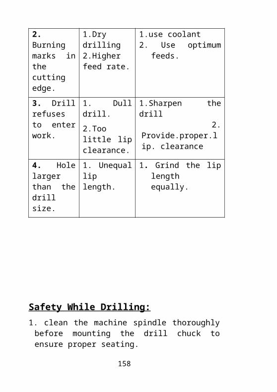
Jaws:
The Vernier contains two jaws; The Fixed jaw and the Movable jaw. The Fixed jaw is a part of the beam. The Movable jaw, the Vernier scale, the Thumb rest and the slider are made as an assembly and this assembly slides on the Beam.
Nibs:
The Fixed and the Movable jaws of the Vernier narrow down the reduce in thickness to form sharper edges. These narrowed down edges of the Vernier help in taking accurate measurements and are known as the nibs of the Vernier.
Clamping Screws:
Clamping screws are used to clamp the Movable jaw assembly to the beam and retain the position of measurements even after the Vernier is lifted outside the area of measurement.
Depth Scale:
Some Vernier calipers are equipped with a blade for measuring the depth of holes and grooves. This blade is called as the Depth scale of the Vernier. The Depth scale slides in a channel machined in the back face of the Beam.
158
Parts of a Vernier Calliper
Parts of a Vernier Caliper
159
The Least Count of The Vernier Scale:
Least count of the Vernier is a least possible measurement that can be made on the Vernier caliper. In the Metric system of measurements, Verniers with 0.02mm and 0.05mm least counts are the most commonly used. The method to find out the least count of both these Verniers is explained below.
Vernier With 0.02mm Least Count:
The Vernier scale is divided into 50 divisions. The 50th division of the Vernier scale coincides with the 49th division of the Main scale. The least count of the Vernier can be found out by the following method:
The number of Vernier scale divisions are divided by the number of coinciding Main scale divisions. The resultant value is subtracted from one unit of the main scale division.
49/50 = 0.98mm1-0.98 = 0.02mm.
Hence the Least count of the Vernier is found out as 0.02mm.
160
Vernier With 0.05mm Least Count:
The Vernier scale is divided into 20 divisions. The 20th division of the Vernier scale coincides with the 19th division of the Main scale. The least count of the Vernier can be found out by the following method.
The number of Vernier scale divisions is divided by the number of coinciding Main scale divisions. The resultant value is subtracted from one unit of the main scale division.
19/20 = 0.95mm.1-0.95 = 0.05mm.
Therefore the Least count of the Vernier is found out as 0.05mm.
Method of Reading a Vernier Caliper :
In the first Fig., the zero of the Vernier scale has moved right to 21 full mm on the Main scale. The nearest coinciding division of the Vernier scale is taken and multiplied with the Least count of the Vernier. Here, the 18th division of the Vernier scale is the nearest division that coincides with a reading of the Main scale. Hence 18 x 0.02mm (Least count) gives 0.36. This value is added to the Main scale reading. Therefore the reading is 31.36. Similarly the second reading is 28.54.
161

Method of Reading of a Vernier Calliper
Method of Reading a Vernier Caliper
162
Types of Vernier Calipers:
1. Dial Vernier.2. Electronic Digital Vernier.3. Vernier Depth Gauge. 4. Vernier Height Gauge.
All the above mentioned caliper work according to the same principle as the Vernier caliper explained before. The only difference being the presence of extra provisions like a Depth scale, Dial, Electronic digital assembly, etc. as per the use. The various types of Verniers are explained with sketches in the succeeding pages.
1. Dial Vernier.
Dial vernier
2. Electronic Digital Vernier.163

Electronic Digital Vernier.
164
3. Vernier Depth Gauge:
Vernier Depth Gauge:
165
4. Vernier Height Gauge: Vernier height gauge consists of an upright steel bar fitted to a steel base. On the bar is a movable jaw with a Vernier scale. A clamp on the bar is connected to the movable jaw by a screw. This screw is used to adjust the Vernier scale to the required position.
Uses: Used to scribe vertical distances from plane surface like the ordinary height gauge, but to an accuracy of 0.02mm. It is also used for measuring between two points. Where extreme accuracy is required, an indicator may be attached to the movable jaw.
166
Vernier Height Gauge
3. Micrometers
These are precision instruments used to measure outside and inside diameter, thickness, etc. in accuracies of 0.01 and 0.001mm. A micrometer is based on the principle of the screw thread, therefore it is called as a screw gauge also. The main advantage of this instrument is the reliability of measurement, ease of handling and better reading. Different types of Micrometers are used depending on the application.
Least Count of the Micrometer:
167
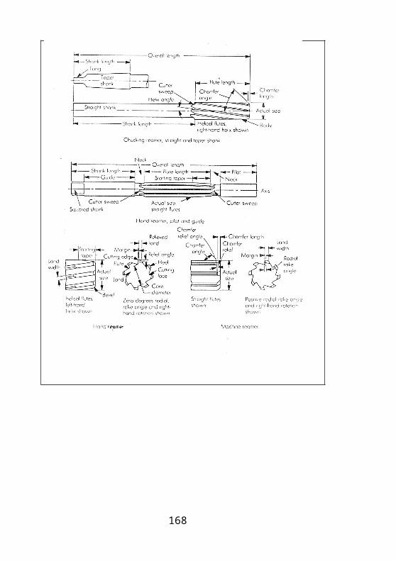
The least count of a micrometer, is the least possible measurement that can be made on a Micrometer. The most commonly used Micrometer has a Least count of 0.01mm. the arrival of this value is explained below.
The circumference of the Micrometer thimble is divided into 50 equal divisions. Each turn of the screw moves equal to its pitch in single – start threads. The pitch of the sleeve is 0.5mm. The pitch of the thimble is divided by the total number of divisions on the sleeve.
0.5/50 = 5/500 = 1/100 = 0.01mm.Thus the least count of the Micrometer is 0.01mm.
Types of Micrometers:
1. Outside micrometer, 2.Inside micrometer3. Depth micrometer, 4.Internal tri point micrometer5. Digital micrometer, 6.Screw thread micrometer7. Flange micrometer, 8.Tubular micrometer
The commonly used types of micrometers are explained below. Sketches are given for the remaining types of micrometers.
How to Read a Micrometer:
168
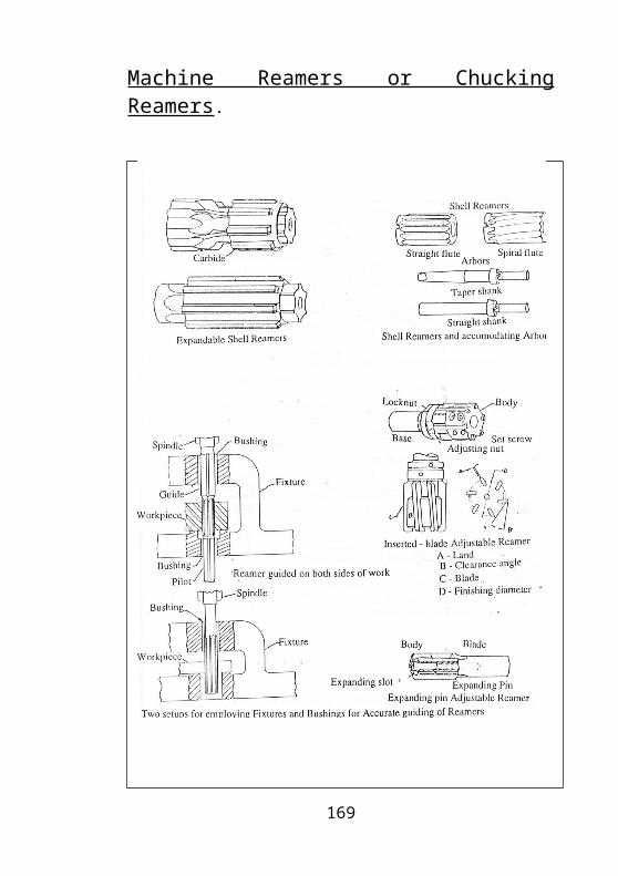
When reading from the Metric micrometer, first take total reading in full millimeters and half millimeters if visible on the sleeve. Add this reading to the reading in hundredths of a millimeter indicated by the graduation on the Thimble, which coincides with the Datum line on the sleeve.
E.g. 1. To measure 16.59mm with the help of a Metric micrometer. The 15mm graduation is visible representing 15mm. There is 11/2mm additionally visible, representing 1.5mm. Line 9 on the thimble coincides with the Datum line on the sleeve, each line representing 0.01mm. I.e., 0.01 x 9 = 0.09mmTherefore the total reading in mm is 15 + 1.5 + 0.09 = 16.59mmSimilarly the second reading is 20.32mm.
169
How To Read A Micrometer
1. Outside Micrometer:
Outside Micrometer
170
It is used to measure the outside diameter, width, thickness, flatness etc. The following are the main parts of an outside Micrometer.
Anvil: It supports the job and provides a reference point. The anvil is pressed permanently or screwed in the frame. The anvil is generally made of carbide.
Frame:
The Frame is a “C” shaped structure. On one side it has the Anvil and on the other side it has the spindle, thimble, sleeve and its assemblies. The frame is sometimes tapered on the side of the anvil to enable measurements to be taken in narrow slots. The size of the outside micrometer is generally engraved on the Frame, such as 0 – 25, 25 – 50mm and soon.
Spindle:
It is made from a special steel, hardened to 62 H.R.C stabilized and precision ground.
Sleeve:
The sleeve is fitted with a highly rigid frame. The vertical line where the measurement is taken is called datum line.
Lock Nut:
171
As is the name it helps in locking the spindle and thus retaining the reading measured. It is fitted on the frame towards the spindle.
Ratchet:
This helps to rotate the spindle while taking measurements, resulting in accuracy and limitation of pressure on work considerably.
1. Outside Micrometer:
Outside Micrometer:
172
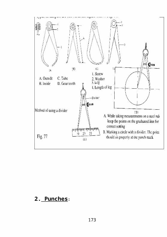
2. Inside Micrometer:
This micrometer is used to measure the inner diameter of holes, cylinders, sleeves, ring, gauges etc. It is similar to outside micrometer but there is no frame and spindle. The measurement is by the end points of the micrometer. As the thimble opens and closes, the contact points move to give the readings. It consists of a micrometer head having a range of different standard lengths.They usually cover a range from 40 – 1000mm. However, smaller ranges are also available.
173
Inside Micrometer
3.Depth Micrometer :
This micrometer is used to measure a blind hole slot under cut and projections. It consists of a flat base attached to micrometer scale. An extension rod of required lengths fit to the sleeve provided to the base. This rod is screwed on top of the thimble. Extension rods are available in various lengths up to 255mm and has a range of 25mm.
174
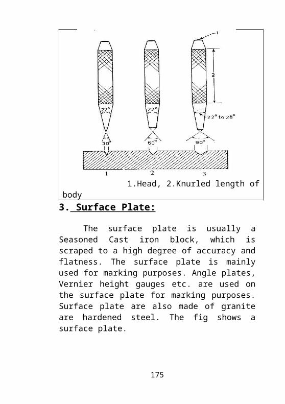
Depth Micrometer
4. Internal Micrometer or Tripoint Micrometer
This Micrometer is equipped with three contact points that allow self-centering for measuring bores. The measuring range is usually from 20 – 200mm. However smaller ranges are available and depend on the requirements.
175
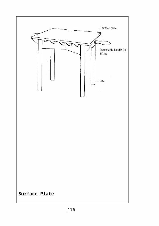
Internal Micrometer or Tripoint Micrometer
5. Digital Micrometer:
The digital micrometer has an accuracy of 0.001mm. It is used to measure mostly finished jobs. A sketch of the digital micrometer is shown in the figure. The advantage of this type of micrometer is that the reading can be directly read to an accuracy of 0.001mm without having to count for the divisions like in an ordinary micrometer.
176
Digital Micrometer
177
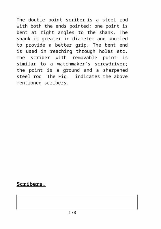
Bevel Protractor
Bevel Protractor
178

Application of a Bevel protractor.
Application of a Bevel protractor
179
How to Read a Bevel Protractor:
1. Note the number of whole degrees zero of main scale and zero of Vernier scale.
2. Proceeding in the same direction between zero of Vernier scale. Note the Vernier line which co-insides with the main scale line. Multiply the number with 5 and added with their number of degrees on the main scale.
The zero line on the Vernier scale is positioned slightly beyond 220. Looking to the same side (Right), on the Vernier scale, we notice that the ninth line coincides exactly with a line on the Main dial. Thus 9 x 5 = 45’ are to be added to 220, which makes the reading of 220 45’.Note: Sometimes there is a confusion regarding towards which direction the Vernier scale should be read. This confusion is eliminated by remembering that “Always read the Vernier scale in the same direction as the Main scale”. The Main scale reading is taken from the zero of the Main scale. So 220 are taken from the right direction of the Main scale zero; Therefore, the coinciding Vernier reading of the right direction is to be taken, which is 45’. Similarly the second reading is 160 15’.
180
How to Read a Bevel Protractor
181
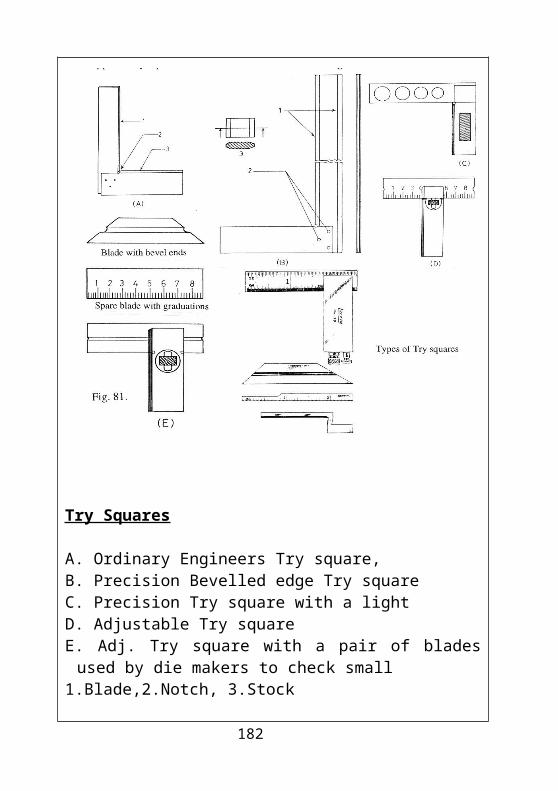
Combination Set Square:
It is extensively used for marking purposes. It mainly consists of three parts.
1. Protractor Head: The steel rule with a slotted face can be fixed to any of these heads. The protractor head is used to mark and measure various angles. The protractor head can be adjusted from 0 – 180 degree. The accuracy of the combination set is 10.
2. Square Head: It is used for checking and marking parallel lines and perpendiculars lines with reference to the edge. It can also be used for checking and marking of 450 angles.
3. Center Head: It forms a center square when mounted on a rule. This can be used for locating center of round, square, and octagonal jobs.
182
Combination Set Square
Combination Set Square
183


![Welcome! [gemini.tli.umn.edu]gemini.tli.umn.edu/materials/Bench-to-Business-Gemini.pdf•Mindset •Tool set •Skill set ... more to the story of bench to business success. ... Keys](https://static.fdocuments.net/doc/165x107/5abb6e367f8b9a8f058c79bd/welcome-mindset-tool-set-skill-set-more-to-the-story-of-bench-to.jpg)