TOOL & DIE MAKER - Bharat Skills€¦ · Tool & Die Maker (Press Tools, Jigs & Fixtures) GOVERNMENT...
76
Tool & Die Maker (Press Tools, Jigs & Fixtures) GOVERNMENT OF INDIA MINISTRY OF SKILL DEVELOPMENT & ENTREPRENEURSHIP DIRECTORATE GENERAL OF TRAINING COMPETENCY BASED CURRICULUM TOOL & DIE MAKER (PRESS TOOLS, JIGS & FIXTURES) (Revised in 2017) CRAFTSMEN TRAINING SCHEME (CTS) NSQF LEVEL- 5 SECTOR –PRODUCTION & MANUFACTURING
Transcript of TOOL & DIE MAKER - Bharat Skills€¦ · Tool & Die Maker (Press Tools, Jigs & Fixtures) GOVERNMENT...

Tool & Die Maker (Press Tools, Jigs & Fixtures)
GOVERNMENT OF INDIA
MINISTRY OF SKILL DEVELOPMENT & ENTREPRENEURSHIP
DIRECTORATE GENERAL OF TRAINING
COMPETENCY BASED CURRICULUM
TOOL & DIE MAKER (PRESS TOOLS, JIGS & FIXTURES)
(Revised in 2017)
CRAFTSMEN TRAINING SCHEME (CTS)
NSQF LEVEL- 5
SECTOR –PRODUCTION & MANUFACTURING

Tool & Die Maker (Press Tools, Jigs & Fixtures)
TOOL & DIE MAKER (Press Tool, Jigs & Fixture)
(Engineering Trade)
(Revised in 2017)
CRAFTSMEN TRAINING SCHEME (CTS)
NSQF LEVEL - 5
Developed By
Ministry of Skill Development and Entrepreneurship
Directorate General of Training
CENTRAL STAFF TRAINING AND RESEARCH INSTITUTE
EN-81, Sector-V, Salt Lake City,
Kolkata – 700 091

Tool & Die Maker (Press Tools, Jigs & Fixtures)
The DGT sincerely acknowledges contributions of the Industries, State Directorates,
Trade Experts, Domain Experts and all others who contributed in revising the curriculum.
Special acknowledgement is extended by DGT to the following expert members who had
contributed immensely in this curriculum.
List of Expert members contributed/ participated for finalizing the course curricula of TDM
(Dies & Moulds) trade held on 16.05.17 at Govt. ITI- Aundh, Pune
S No. Name & Designation
Shri/Mr/Ms Organization Remarks
Industry Experts
1. Dr. K C Vora, Sr. Dy. Director
& Head, Arai Academy
The Automotive Research
Association of India, S.No.102,
Vetal Hill, Off Paud Road, Kothrud,
Pune
Chairman
2. Jayanta Patra, Sr. Manager Micromatic Machine Tools (P) Ltd.
240/241,11th Main, 3rd Phase,
Peenya Industrial Area, Bangalore
Member
3. Kashinath M. Patnasetty, Head
- Application Support Group
Ace Designers Ltd. Plot No. 7&8, II
Phase Peenya Industrial Area,
Bangalore
Member
4. Sunil Khodke, Training
Manager
Bobst India Pvt Ltd Pirangut,
Mulashi, Pune
Member
5. Lokesh Kumar, Manager
Training Academy
Volkswagen India Pvt Ltd Pune Member
6. Shriram Tatyaba Khaire,
Executive Engineering
Sulzer India Pvt. Ltd., Kondhapuri,
Shirur, Pune
Member
7. Milind P Desai, Sr. Shift
Engineer
Atlas Copco (I) Ltd., Dapodi, Pune Member
8. Shrikant Mujumdar, DGM John Deere India Pvt. Ltd., Pune -
Nagar Road, Sanaswadi, Pune
Member
9. G.D. Rajkumar, Director GTTI, Coimbatore Expert
10. Milind Sanghai, Team
Manager
Alfa Laval India Ltd., Dapodi, Pune Member
11. Rajesh Menon Unit Manager Alfa Laval India Ltd., Dapodi, Pune Member
12. N K A Madhuubalan, DGM -
QC, QA & SMPS
Sandvik Asia Pvt.Ltd., Dapodi, Pune Member
13. Irkar Balaji, Sr. Engineer Mfg. Premium Transmission Ltd.,
Chinchwad, Pune
Member
ACKNOWLEDGEMENT

Tool & Die Maker (Press Tools, Jigs & Fixtures) 14. Rajendra Shelke, Sr. Engineer
Mfg.
Premium Transmission Ltd.,
Chinchwad, Pune - 19
Member
15. Bhagirath Kulkarni, Manager
Maintenance
Tata Ficosa Auto Sys Ltd.,
Hinjawadi, Pune
Member
16. Rohan More, Hr & Admin Tata Ficosa Auto Sys Ltd.,
Hinjawadi, Pune
Member
17. G. Venkateshwaran, TEC
Manager- Corporate
Responsibility
Cummins India Ltd. Member
18. Mahesh Dhokale, Engineer Tata Toyo Radiator Ltd Member
19. Pankaj Gupta DGM- HR & IR Tata Toyo Radiator Ltd Member
20. S K Joshi Head - Business
Development
Radheya Machining Ltd Pune-
Nagar Road, Sanaswadi, Pune.
Member
21. A L Kulkarni, DGM Mfg. Pmt Machines Ltd Pimpri, Pune Member
22. S V Karkhanis, DGM Planning Pmt Machines Ltd Pimpri, Pune Member
23. Kiran Shirsath, Asso. Manager
M.E.
Burckhardt Compression Pvt. Ltd.,
Ranjangaon, Pune
Member
24. Ajay Dhuri, Manager Tata Motors Ltd Pimpri, Pune Member
25. Arnold Cyril Martin, DGM Godrej & Boyce Mfg Co Ltd.,
Mumbai
Member
26. Ravindra L. More Mahindra CIE Automotive Ind. Ltd.
Ursc-Pune
Member
27. Kushagra P. Patel NRB Bearings Ltd., Chiklthana
Aurangabad
Member
28. M. M. Kulkarni, Sr. Manager -
Tool room
NRB Bearings Ltd., Chiklthana
Aurangabad
Member
DGT & Training Institute
29. Nirmalya Nath,
Asst. Director of Trg.
CSTARI, Kolkata Member cum
Co-coordinator
30. P K Vijayan, Sr Manager
Training
Gedee Technical Training Institute,
734 Avinashi Road, Coimbatore
Member
31. Rasal G.S., Instructor ITI Aundh, Pune Member
32. T.P. Ramchandran, Sr.
Counselor
GTTI, Coimbatore Member
33. Kutte R.J., Instructor ITI Aundh Pune Member
34. Saroj Kumar Mondal, Ex T.O. MSME Tool Room, Kolkata Expert
35. Debrabrata Mondal, V.I. ATI Kolkata Expert

Tool & Die Maker (Press Tools, Jigs & Fixtures)
S
No. Topics Page No.
1. Course Information 1
2. Training System 2-5
3. Job Role 6
4. General Information 7-8
5. NSQF Level Compliance 9
6. Learning/ Assessment Outcome 10-12
7. Learning Outcome with Assessment Criteria 13-23
8. Syllabus 24-39
9. Syllabus - Core Skill
9.1 Core Skill – Workshop Calculation & Science and
Engineering Drawing
40-47
9.2 Core Skill – Employability Skill 48-51
10. Annexure I
List of Trade Tools & Equipment 52-62
List of Tools & Equipment for Employability Skill 62
Annexure A 63-64
Annexure A (I) 65-66
Annexure A (II) 67-70
11. Annexure II - Format for Internal Assessment 71
CONTENT
S

1
Tool & Die Maker (Press Tools, Jigs & Fixtures)
During the two years duration, a candidate is trained on subjects- Professional Skill,
Professional Knowledge, Engineering Drawing, Workshop Science & Calculation and
Employability Skills. In addition to this, a candidate is entrusted to make/do project work and
Extra Curricular Activities to build up confidence. The practical skills are imparted in simple to
complex manner & simultaneously theory subject is taught in the same fashion to apply
cognitive knowledge while executing task.
The course covers the detail aspect of mould making& testing. The broad components
covered under Professional Skill subject are as below:
1st Semester– The practical part starts with basic fitting covering components like filing,
sawing, drilling, tapping, chipping, grinding and different fits. The accuracy proposed is of
±0.05mm and angular accuracy of 1. Different turning operations on lathe viz., plain, facing,
boring, grooving, step turning, parting, chamfering, knurling and different thread cutting by
setting the different parameter, are covered in the practical part.
2ndSemester– Different milling operations (plain, stepped, angular, dovetail, T-slot, contour,
gear) along with surface & cylindrical grinding to an accuracy of ±0.02mm are covered. In
addition, solid modeling of mould in CAD & Pro E taught setting and execution of welding is
also a component in this semester.
3rdSemester– Setting, operation and programming of CNC turn centre and CNC machining
centre to produce components are performed in this semester. 2D & 3D machining with CAM
software is also performed. Manufacture drill jig and fixture is also part of the practical. EDM &
wire EDM operation to produce components with an accuracy of ±0.02mm is covered.
Construction of blanking and piercing tool is done and testing of same is also performed.
4th Semester– Basic construction of Hydraulic & Pneumatic circuits and basic functioning of
electrical circuit and sensors are covered in this semester. Construction of compound and
progressive tools is done testing of same is executed. Simple repair and overhauling of different
machines viz., drill, milling & lathe is covered. Making of ‘V’ bending tool and draw tool are
carried out and testing is also undertaken.
1. COURSE INFORMATION

2
Tool & Die Maker (Press Tools, Jigs & Fixtures)
2.1 GENERAL
The Directorate General of Training (DGT) under Ministry of Skill Development &
Entrepreneurship offers a range of vocational training courses catering to the need of different
sectors of Labour market. The vocational training programmes are running under the aegis of
National Council of Vocational Training (NCVT). Craftsman Training Scheme (CTS) and
Apprenticeship Training Scheme (ATS) are two pioneer programmes under NCVT for
propagating vocational training.
TOOL & DIE MAKER (Press Tools and Jigs & Fixtures)trade under CTS is one of the
popular courses delivered nationwide through network of ITIs. The course is of two years (04
semester) duration. It mainly consists of Domain area and Core area. In the Domain area, Trade
Theory & Practical impart professional skills and knowledge, while Core area imparts Workshop
Calculation and Science, Engineering Drawing and Employability Skills impart requisite core
skill & knowledge and life skills. After passing out the training programme, the trainee is
awarded National Trade Certificate (NTC) by NCVT which is recognized worldwide.
Candidates broadly need to demonstrate that they are able to:
Read & interpret technical parameters/documentation, plan and organize work processes,
identify necessary materials and tools;
Perform task with due consideration to safety rules, accident prevention regulations and
environmental protection stipulations;
Apply professional knowledge, core skills & employability skills while performing the
job of a Tool & Die Maker (Press Tools and Jigs & Fixtures) and machining work.
Check the job/components as per drawing for functioning identify and rectify errors in
job/components.
Document the technical parameters related to the task undertaken.
2.2 CAREER PROGRESSION PATHWAYS:
Can appear in 10+2 examination through National Institute of Open Schooling (NIOS)
for acquiring higher secondary certificate and can go further for General/ Technical
education.
Can take admission in diploma course in notified branches of Engineering by lateral
entry.
Can join Apprenticeship programme in different types of industries leading to National
Apprenticeship certificate (NAC).
2. TRAINING SYSTEM

3
Tool & Die Maker (Press Tools, Jigs & Fixtures)
Can join Crafts Instructor Training Scheme (CITS) in the trade for becoming instructor in
ITIs.
2.3 COURSE STRUCTURE:
Table below depicts the distribution of training hours across various course elements
during a period of two years (04 semesters):
S No. Course Element Notional Training
Hours
1 Professional Skill (Trade Practical) 2209
2 Professional Knowledge (Trade Theory) 510
3 Workshop Calculation & Science 170
4 Engineering Drawing 255
5 Employability Skills 110
6 Library & Extracurricular activities 146
7 Project work 240
8 Revision & Examination 520
Total 4160
2.4 ASSESSMENT & CERTIFICATION:
The trainee will be tested for his skill, knowledge and attitude during the period of course
and at the end of the training programme as notified by Govt. of India from time to time. The
Employability Skills will be covered and tested in first two semesters only for two semesters
course and tested at the end of 4th semester for 4 semester system for NCVT/German Exam.
a) The Internal assessment during the period of training will be done by Formative Assessment
Method by testing for assessment criteria listed against learning outcomes. The training institute
have to maintain individual trainee portfolio as detailed in assessment guideline. The marks of
internal assessment will be as per the template (Annexure – II).
b) The final assessment will be in the form of summative assessment method. The All India
Trade Test for awarding NTC will be conducted by NCVT as per guideline of Govt. of India.
The pattern and marking structure is being notified by Govt. of India from time to time. The
learning outcome and assessment criteria will be basis for setting question papers for final
assessment. The examiner during final examination will also check individual trainee’s profile as

4
Tool & Die Maker (Press Tools, Jigs & Fixtures) detailed in assessment guideline (German Marking System) before giving marks for practical
examination.
2.4.1 PASS REGULATION:
For the purposes of determining the overall result, weightage of 25%is applied to each
semester examination. The minimum pass percent for Practical is 60% & minimum pass percent
for Theory subjects is 40%.
2.4.2 ASSESSMENT GUIDELINE:
Appropriate arrangements should be made to ensure that there will be no artificial
barriers to assessment. The nature of special needs should be taken into account while
undertaking assessment. Due consideration to be given while assessing for teamwork,
avoidance/reduction of scrap/wastage and disposal of scrap/wastage as per procedure, behavioral
attitude, sensitive to environment and regularity in training. The sensitivity towards OSHE and
self-learning attitude to be considered while assessing competency.
Assessment will be evidence based comprising the following:
Job carried out in labs/workshop
Record book/ daily diary
Answer sheet assessment
Viva-voce
Progress chart
Attendance and punctuality
Assignment
Project work
Evidence of internal assessment to be preserved until forthcoming semester examination for
audit and verification by examination body. The following marking pattern to be adopted while
assessing:
Performance Level Evidence
(a) Weightage in the range of 60 -75% to be allotted during assessment
For performance in this grade, the candidate
should produce work which demonstrates
attainment of an acceptable standard of
craftsmanship with occasional guidance, and
due regard for safety procedures and practices.
Demonstration of good skill in the use of
hand tools, machine tools and workshop
equipment.
Below 70% tolerance dimension
achieved while undertaking different
work with those demanded by the
component/job.

5
Tool & Die Maker (Press Tools, Jigs & Fixtures)
A fairly good level of neatness and
consistency in the finish.
Occasional support in completing the
project/job.
(b)Weightage in the range of 75- 90% to be allotted during assessment
For this grade, a candidate should produce
work which demonstrates attainment of a
reasonable standard of craftsmanship, with
little guidance, and regard for safety
procedures and practices.
Good skill levels in the use of hand
tools, machine tools and workshop
equipment.
70-80% tolerance dimension achieved
while undertaking different work with
those demanded by the component/job.
A good level of neatness and
consistency in the finish.
Little support in completing the
project/job.
(c) Weightage in the range of above 90% to be allotted during assessment
For performance in this grade, the candidate,
with minimal or no support in organization and
execution and with due regard for safety
procedures and practices, has produced work
which demonstrates attainment of a high
standard of craftsmanship.
High skill levels in the use of hand tools,
machine tools and workshop equipment
Above 80% tolerance dimension
achieved while undertaking different
work with those demanded by the
component/job.
A high level of neatness and consistency
in the finish.
Minimal or no support in completing the
project.

6
Tool & Die Maker (Press Tools, Jigs & Fixtures)
Tool & Die Maker (Press Tools, Jigs & Fixtures):
Tool and Die Makers build, repair and modify custom made prototypes or special tools,
Press Tools, Jigs, Fixtures and various types of mechanical devices. Press Tools are metal forms
used for Sheet metal cutting and forming. Tool and Die Makers fabricate various parts, like
pieces of a puzzle, which require perfect fitting. While this occupation is closely allied with the
machinist trade and encompasses many of the same skills, Tool and Die Makers usually
specialize in jobs spending more time in fitting and assembling precision components which are
required for sheet metal cutting forms. A Tool and Die maker’s work depends on precise
measurements and accuracy, as such math skills are important. Also, they must be able to read
and interpret information from design drawings and specifications to fabricate all types of Press
Tools Jigs and Fixtures. Being mechanical minded is an additional skill.
Plan and organize assigned work; and detect and resolve issues during execution.
Demonstrate possible solutions and agree tasks within the team. Communicate with required
clarity and understand technical English, sensitive to environment, self-learning and
productivity.
The trainee after completion of this course may be designated as Tool & Die Maker
(Press Tools, Jigs & Fixtures) according to nature of work done.
Reference NCO-2015:
i. 7222.0200
ii. 7222.0300
iii. 7223.0200
3. JOB ROLE

7
Tool & Die Maker (Press Tools, Jigs & Fixtures)
Name of the Trade Tool & Die Maker (Press Tools, Jigs & Fixtures)
NCO - 2015 7222.0200, 7222.0300, 7223.0200
NSQF Level Level – 5
Duration of Craftsmen
Training Two years (Four semesters each of six months duration)
Entry Qualification Passed 10
th Class with Science and Mathematics under 10+2 system of
education or its equivalent
Unit Strength (No. Of
Students) 16 (Max. supernumeraries seats:5)
Space Norms 166 Sq. m
Power Norms 20 KW
Instructors Qualification for
1. Tool & Die Maker
(Press Tools, Jigs &
Fixtures) Trade
Degree in Mechanical Engineering from recognized Engineering
College/university with minimum two-year experience in the relevant
field.
OR
Diploma in Tool and Die making from recognized board of technical
education with three-year experience in the relevant field.
OR
10th
Class Pass + NTC/NAC in the Trade of “Tool and Die Maker (Press
Tool and Jigs & Fixtures)” with three-year post qualification experience
in the relevant field.
Desirable:
Preference will be given to a candidate with CIC(Craft Instructor
Certificate) in TOOL & DIE Maker (Press Tool and Jigs & Fixtures)
trade.
Out of two Instructors required for the unit of 2(1+1), one must have
Degree/Diploma and other must have NTC/NAC qualifications.
2. Workshop
Calculation & Science
Degree in Mechanical Engineering with two-year practical experience in
a tool room.
OR
Diploma in TOOL & DIE Making with three-year practical experience
in a tool room.
Desirable: Craft Instructor Certificate in RoD&A course under NCVT.
4. GENERAL INFORMATION

8
Tool & Die Maker (Press Tools, Jigs & Fixtures) 3. Engineering
Drawing
Degree in Mechanical Engineering with one year experience.
OR
Diploma in Mechanical Engineering with two-year experience.
OR
NTC/ NAC in the Draughtsman (Mechanical) with three-year
experience.
OR Post Diploma in Tool Design/ Diploma in Tool & Die making (Press
Tool and Jigs & Fixtures) with two-year experience in Tool Design
Department.
OR
NTC/ NAC in Tool & Die making (Press Tool, Jigs & Fixtures) with
three-year experience in Tool Design Department.
Desirable:
Craft Instructor Certificate in RoD&A course under NCVT.
4. Employability Skill MBA OR BBA with two-year experience OR Graduate in Sociology/
Social Welfare/ Economics with two-year experience OR Graduate/
Diploma with two-year experience and trained in Employability Skills
from DGT institutes.
AND
Must have studied English/ Communication Skills and Basic Computer
at 12th/ Diploma level and above.
OR
Existing Social Studies Instructors duly trained in Employability Skills
from DGT institutes.
List of Tools and
Equipment As per Annexure – I
Distribution of training on Hourly basis: (Indicative only)
Total
Hours/
Week
Trade
Practical
Trade
Theory
Workshop Cal.
&Sc.
Engg.
Drawing/
Tool Design
Drawing
Employability
Skills
Extra-
curricular
Activity
40 Hours 25 Hours 6 Hours 2 Hours 3 Hours 2 Hours 2 Hours

9
Tool & Die Maker (Press Tools, Jigs & Fixtures)
NSQF level for Tool & Die Maker (Press Tools, Jigs & Fixtures) trade under CTS:
Level 5
As per notification issued by Govt. of India dated 27.12.2013 on National Skill
Qualification Framework total 10 (Ten) Levels are defined.
Each level of the NSQF is associated with a set of descriptors made up of five outcome
statements, which describe in general terms, the minimum knowledge, skills and attributes that
a learner needs to acquire in order to be certified for that level.
Each level of the NSQF is described by a statement of learning outcomes in five domains,
known as level descriptors. These five domains are:
a. Process
b. Professional Knowledge
c. Professional Skill
d. Core Skill
e. Responsibility
The broad learning outcome of Tool & Die Maker (Press Tools, Jigs & Fixtures) trade
under CTS mostly matches with the Level descriptor at Level- 5.
The NSQF level-5 descriptor is given below:
Level Process
Required
Professional
Knowledge
Professional
Skill Core Skill Responsibility
Level 5 Job that requires
well developed
skill, with clear
choice of
procedures in
familiar context.
Knowledge
of facts,
principles,
processes and
general
concepts, in a
field of
work
or study.
A range of
cognitive and
practical skills
required to
accomplish
tasks and solve
problem by
selecting and
applying basic
methods, tools,
materials and
information.
Desired
mathematical
skill,
understanding of
social, political
and some skill of
collecting and
organizing
information,
communication
Responsibility for
own work and
learning and some
responsibility for
other’s works and
learning.
5. NSQF LEVEL COMPLIANCE

10
Tool & Die Maker (Press Tools, Jigs & Fixtures)
Learning outcomes are a reflection of total competencies of a trainee and assessment will
be carried out as per the assessment criteria.
6.1 GENERIC LEARNING OUTCOME
1. Recognize & comply with safe working practices, environment regulation and
housekeeping.
2. Understand and explain different mathematical calculation & science in the field of
study. [Different mathematical calculation & science -Work, Power & Energy, Algebra,
Geometry & Mensuration, Trigonometry, Heat & Temperature, Levers & Simple
machine, graph, Statistics, Centre of gravity, Power transmission, Pressure]
3. Interpret specifications, different engineering drawing and apply for different application
in the field of work. [Different engineering drawing-Geometrical construction,
Dimensioning, Layout, Method of representation, Symbol, scales, Different Projections,
Machined components & different thread forms, Assembly drawing, Sectional views]
4. Select and ascertain measuring instrument and measure dimension of components and
record data.
5. Explain the concept in productivity, quality tools, and labour welfare legislation and
apply such in day-to-day work to improve productivity & quality.
6. Explain energy conservation, global warming and pollution and contribute in day-to-day
work by optimally using available resources.
7. Explain personnel finance, entrepreneurship and manage/organize related task in day-to-
day work for personal & societal growth.
8. Plan and organize the work related to the occupation.
9. Interpret specifications, different Dies & Moulds design drawing and apply for different
application in the field of work. [Different Tool Design Drawing-Hand injection moulds,
Mould base, two cavity injection mould in different constructional featured,]
6.2 SPECIFIC LEARNING OUTCOME
Semester – I
10. Plan and organize the work to make job as per specification applying different types of
basic fitting operation and check for dimensional accuracy. [Basic fitting operation –
6. LEARNING/ ASSESSMENT OUTCOME

11
Tool & Die Maker (Press Tools, Jigs & Fixtures)
Filing, Marking, Hack sawing, Drilling, Taping, chipping and Grinding etc. Accuracy: ±
0.1mm]
11. Make different fit of components for assembling as per required tolerance observing
principle of interchangeability and check for functionality. [Different Fit –Open, Angular,
& Square Fit; Required tolerance: ±0.05 mm, angular tolerance: 1 degree.]
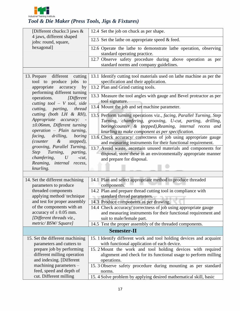
12. Set different shaped jobs on different chuck and demonstrate conventional lathe machine
operation observing standard operation practice. [Different chucks:3 jaws & 4 jaws,
different shaped jobs: round, square, hexagonal]
13. Prepare different cutting tool to produce jobs to appropriate accuracy by performing
different turning operations. Different cutting tool – V tool, side cutting, parting, thread
cutting (both LH & RH),Appropriate accuracy: ±0.06mm, Different turning operation –
Plain, facing, drilling, boring (counter & stepped), grooving, Parallel Turning, Step
Turning, parting, chamfering, U -cut, Reaming, internal recess, knurling.
14. Set the different machining parameters to produce threaded components applying
method/ technique and test for proper assembly of the components with an accuracy of ±
0.05 mm. [Different threads viz., metric/ BSW/ Square]
Semester – II
15. Set the different machining parameters and cutters to prepare job by performing different
milling operation and indexing. [Different machining parameters – feed, speed and depth
of cut. Different milling operations – plain, stepped, angular, dovetail, T-slot, contour,
gear milling]
16. Produce components of high accuracy by surface grinding operation.[Accuracy of +/-
0.02 mm]
17. Produce components of high accuracy by cylindrical grinding operations. [Accuracy of
+/- 0.02mm.]
18. Sharpen different cutter or multipoint cutting tool. [Different cutters – end mill cutter,
side & face milling cutter, single angle cutter, Reamer]
19. Develop isometric drawing and solid modelling of mould using CAD & Pro-E.
20. Set the welding plant with appropriate parameters & perform different welding
operations.[Appropriate parameter- electrode size, voltage, current, position, travel
speed, torch angle.]
Semester – III
21. Manufacturing of drill Jig and produce component on drill machine by using Jigs and
check for correctness. (Simple template & Plate Jig)
22. Manufacturing of fixtures (milling, turning and grinding) & test.
23. Set (both job and tool) CNC turning centre and produce components as per drawing by
preparing part programme.

12
Tool & Die Maker (Press Tools, Jigs & Fixtures)
24. Set (both job and tool) CNC machining centre vertical and produce components as per
drawing by preparing part programme.
25. Perform 2D & 3D machining with CAM software.
26. Produce components using Electric Discharge Machine (EDM) and Wire EDM as per
drawing by preparing part programme with accuracy of ± 0.02mm.
27. Manufacturing of blanking (simple) die set for square/ round/ rectangular/elliptical
component and verify the component.
28. Construct a Piercing & Blanking tool & test and verify the component.
Semester – IV
29. Construct circuit of pneumatics and hydraulics observing standard operating procedure
and safety aspect.
30. Demonstrate function of basic electrical circuit and sensors.
31. Construct a Compound Tool & test and verify the component.
32. Construct a Progressive tool & test and verify the component.
33. Plan and perform simple repair, overhauling of different machines and check for
functionality. [Different Machines – Drilling Machine, milling machine and Lathe]
34. Manufacture “V” bending tool & test.
35. Construct a draw tool (single stage) and test to verify the component.

13
Tool & Die Maker (Press Tools, Jigs & Fixtures)
GENERIC LEARNING/ ASSESSABLE OUTCOME
LEARNING/ ASSESSABLE
OUTCOMES ASSESSMENT CRITERIA
1. Recognize & comply with
safe working practices,
environment regulation and
housekeeping.
1.1 Follow and maintain procedures to achieve a safe
working environment in line with occupational health
and safety regulations and requirements.
1.2 Recognize and report all unsafe situations according to
site policy.
1.3 Identify and take necessary precautions on fire and safety
hazards and report according to site policy and
procedures.
1.4 Identify, handle and store/dispose of
dangerous/unsalvageable goods and substances according
to site policy and procedures following safety regulations
and requirements.
1.5 Identify and observe site policies and procedures with
regard to illness or accident.
1.6 Identify safety alarms accurately.
1.7 Report supervisor/ Competent authority in the event of
accident or sickness of any staff and record accident details
correctly according to site accident/injury procedures.
1.8 Identify and observe site evacuation procedures according
to site policy.
1.9 Identify Personal Productive Equipment (PPE) and use the
same as per related working environment.
1.10 Identify basic first aid and use them under different
circumstances.
1.11 Identify different fire extinguisher and use the same as per
requirement.
1.12 Identify environmental pollution & contribute to avoidance
of same.
1.13 Take opportunities to use energy and materials in an
environmentally friendly manner.
1.14 Avoid waste and dispose waste as per procedure.
1.15 Recognize different components of 5S and apply the same
in the working environment.
2. Understand, explain
different mathematical
calculation & science in the
2.1 Explain concept of basic science related to the field such as
Material science, Mass, weight, density, speed, velocity,
heat & temperature, force, motion, pressure, heat treatment,
7. LEARNING OUTCOME WITH ASSESSMENT CRITERIA

14
Tool & Die Maker (Press Tools, Jigs & Fixtures)
field of study including
basic electrical and apply in
day-to-day work.[Different
mathematical calculation &
science -Work, Power &
Energy, Algebra, Geometry
& Mensuration,
Trigonometry, Heat &
Temperature, Levers &
Simple machine, graph,
Statistics, Centre of gravity,
Power transmission,
Pressure]
centre of gravity, friction.
2.2 Measure dimensions as per drawing.
2.3 Use scale/ tapes to measure for fitting to specification.
2.4 Comply with given tolerance.
2.5 Prepare list of appropriate materials by interpreting detailed
drawings and determine quantities of such materials.
2.6 Ensure dimensional accuracy of assembly by using different
instruments/gauges.
2.7 Explain basic electricity, insulation & earthing.
3. Interpret specifications,
different engineering
drawing and apply for
different application in the
field of work. [Different
engineering drawing-
Geometrical construction,
Dimensioning, Layout,
Method of representation,
Symbol, scales, Different
Projections, Machined
components & different
thread forms, Assembly
drawing, Sectional views,
Estimation of material]
3.1 Read and interpret the information on drawings and apply in
executing practical work.
3.2 Read and analyse the specification to ascertain the material
requirement, tools, and machining/assembly/maintenance
parameters.
3.3 Encounter drawings with missing/unspecified key
information and make own calculations to fill in missing
dimension/parameters to carry out the work.
4. Select and ascertain
measuring instrument and
measure dimension of
components and record data.
4.1 Select appropriate measuring instruments such as
micrometers, vernier calipers, dial gauge, bevel protector
and height gauge (as per tool list).
4.2 Ascertain the functionality & correctness of the instrument.
4.3 Measure dimension of the components & record data to
analyse with the given drawing/measurement.
5. Explain the concept in
productivity, quality tools,
and labour welfare legislation
and apply such in day-to-day
work to improve productivity
5.1 Explain the concept of productivity and quality tools and
apply during execution of job.
5.2 Understand the basic concept of labour welfare legislation
and adhere to responsibilities and remain sensitive towards
such laws.

15
Tool & Die Maker (Press Tools, Jigs & Fixtures)
and quality.
5.3 Knows benefits guaranteed under various acts.
6. Explain energy conservation,
global warming, pollution
and contribute in day-to-day
work by optimally using
available resources.
6.1 Explain the concept of energy conservation, global
warming, pollution and utilize the available resources
optimally & remain sensitive to avoid environment
pollution.
6.2 Dispose waste following standard procedure.
7. Explain personnel finance,
entrepreneurship and
manage/organize related task
in day-to-day work for
personal & societal growth.
7.1 Explain personnel finance and entrepreneurship.
7.2 Explain role of various schemes and institutes for self-
employment i.e. DIC, SIDA, SISI, NSIC, SIDO, Idea for
financing/ non-financing support agencies to familiarize
with the Policies/Programmes, procedure and the available
scheme.
7.3 Prepare Project report to become an entrepreneur for
submission to financial institutions.
8. Plan and organize the work
related to the occupation.
8.1 Use documents, drawings and recognize hazards in the work
site.
8.2 Plan workplace/ assembly location with due consideration to
operational stipulation.
8.3 Communicate effectively with others and plan project tasks.
8.4 Assign roles and responsibilities of the co-trainees for
execution of the task effectively and monitor the same.
9. Interpret specifications,
different Dies & Moulds
design drawing and apply for
different application in the
field of work. [Different Tool
Design Drawing-Hand
injection moulds, Mould
base, two cavity injection
mould in different
constructional feature]
9.1 Identify a single cavity Injection Mould.
9.2 Identify different types of Mould Base.
9.3 Identify the different parts of an Injection Mould.
9.4 Explain the constructional features of an Injection Mould.
9.5 Explain the method of design an Injection Mould.

16
Tool & Die Maker (Press Tools, Jigs & Fixtures)
SPECIFIC LEARNING/ ASSESSABLE OUTCOME
Semester-I
LEARNING/ ASSESSABLE
OUTCOMES ASSESSMENT CRITERIA
10. Plan and organize the work
to make job as per
specification applying
different types of basic
fitting operation and check
for dimensional accuracy.
[Basic fitting operation –
Filing, Marking, Hack
sawing, Drilling, Taping,
chipping and Grinding etc.
Accuracy: ± 0.1mm]
10.1 Plan & Identify tools, instruments and equipments for marking
and make this available for use in a timely manner.
10.2 Select raw material and visual inspect for defects.
10.3 Mark as per specification applying desired mathematical
calculation and observing standard procedure.
10.4 Measure all dimensions in accordance with standard
specifications and tolerances.
10.5 Identify Hand Tools for different fitting operations and make
these available for use in a timely manner.
10.6 Prepare the job for Hack-sawing, chiselling, filing, drilling,
tapping, grinding.
10.7 Perform basic fitting operations viz., Hack-sawing, filing,
drilling, tapping and grinding to close tolerance as per
specification to make the job.
10.8 Observe safety procedure during above operation as per
standard norms and company guidelines.
10.9 Check for dimensional accuracy as per standard procedure.
10.10 Avoid waste, ascertain unused materials and components for
disposal, store these in an environmentally appropriate manner
and prepare for disposal.
11. Make different fit of
components for assembling
as per required tolerance
observing principle of
interchangeability and check
for functionality. [Different
Fit –Open, Angular, &
Square Fit; Required
tolerance: ±0.05 mm,
angular tolerance: 1 degree]
11.1 Plan and organize for fitting job.
11.2 Select raw material, tools & equipments.
11.3 Perform the work pieces for fitting according to tolerances and
interchangeability.
11.4 Check all dimensions and interchangeability in accordance
with drawing and rectify, if required.
12. Set different shaped jobs on
different chuck and
demonstrate conventional
lathe machine operation
observing standard
operation practice.
12.1 Identify and acquaint with lathe machine operation with its
components.
12.2 Identify different work holding devices and acquaint with
functional application of each device.
12.3 Mount the appropriate work holding device and check for its
functional usage to perform turning operations.
17
Tool & Die Maker (Press Tools, Jigs & Fixtures)
[Different chucks:3 jaws &
4 jaws, different shaped
jobs: round, square,
hexagonal]
12.4 Set the job on chuck as per shape.
12.5 Set the lathe on appropriate speed & feed.
12.6 Operate the lathe to demonstrate lathe operation, observing
standard operating practice.
12.7 Observe safety procedure during above operation as per
standard norms and company guidelines.
13. Prepare different cutting
tool to produce jobs to
appropriate accuracy by
performing different turning
operations. [Different
cutting tool – V tool, side
cutting, parting, thread
cutting (both LH & RH),
Appropriate accuracy: -
±0.06mm, Different turning
operation – Plain turning,
facing, drilling, boring
(counter & stepped),
grooving, Parallel Turning,
Step Turning, parting,
chamfering, U -cut,
Reaming, internal recess,
knurling.
13.1 Identify cutting tool materials used on lathe machine as per the
specification and their application.
13.2 Plan and Grind cutting tools.
13.3 Measure the tool angles with gauge and Bevel protractor as per
tool signature.
13.4 Mount the job and set machine parameter.
13.5 Perform turning operations viz., facing, Parallel Turning, Step
Turning, chamfering, grooving, U-cut, parting, drilling,
boring(counter & stepped),Reaming, internal recess and
knurling to make component as per specification.
13.6 Check accuracy/ correctness of job using appropriate gauge
and measuring instruments for their functional requirement.
13.7 Avoid waste, ascertain unused materials and components for
disposal, store these in an environmentally appropriate manner
and prepare for disposal.
14. Set the different machining
parameters to produce
threaded components
applying method/ technique
and test for proper assembly
of the components with an
accuracy of ± 0.05 mm.
[Different threads viz.,
metric/ BSW/ Square]
14.1 Plan and select appropriate method to produce threaded
components.
14.2 Plan and prepare thread cutting tool in compliance with
standard thread parameters.
14.3 Produce components as per drawing.
14.4 Check accuracy/ correctness of job using appropriate gauge
and measuring instruments for their functional requirement and
suit to male/female part.
14.5 Test the proper assembly of the threaded components.
Semester-II
15. Set the different machining
parameters and cutters to
prepare job by performing
different milling operation
and indexing. [Different
machining parameters –
feed, speed and depth of
cut. Different milling
15. 1 Identify different work and tool holding devices and acquaint
with functional application of each device.
15. 2 Mount the work and tool holding devices with required
alignment and check for its functional usage to perform milling
operations.
15. 3 Observe safety procedure during mounting as per standard
norms.
15. 4 Solve problem by applying desired mathematical skill, basic

18
Tool & Die Maker (Press Tools, Jigs & Fixtures)
operations – plain, stepped,
angular, dovetail, T-slot,
contour, gear milling]
methods, tools, materials and collect and organize information
during setting.
16. Produce components of high
accuracy by surface
grinding operation.
[accuracy of +/- 0.02 mm]
16.1 Plan and select appropriate method to produce the work piece
as per drawing.
16.2 Select appropriate tools, equipment and machine to produce the
work piece as per drawing and make these available for use in
a timely manner.
16.3 Grind the cutting tool following standard operating practice.
16.4 Set the job on grinding machine and grind the surfaces as per
specification/drawing (parallel and stepped) following standard
operating practice.
16.5 Check the dimension of parallel and stepped job by precession
instrument (micrometer).
16.6 Observe safety precautions during operation during machining.
16.7 Check for desired performance.
17. Produce components of high
accuracy by cylindrical
grinding operations.
[accuracy of +/- 0.02mm.]
17.1 Set the machining parameter and produce the component
applying technique/ machine.
17.2 External parallel grinding on cylindrical grinding.
17.3 Internal parallel grinding with cylindrical grinding machine
using chuck/ collet.
17.4 Step grinding in cylindrical grinding machine (external).
17.5 Taper grinding on cylindrical grinding machine (external).
17.6 Check the accuracy of the component using instruments.
18. Sharpen different cutter or
multipoint cutting tool.
[Different cutters – end mill
cutter, side & face milling
cutter, single angle cutter,
Reamer]
18.1 Plan and set the cutter or multipoint cutting tool to the
machine.
18.2 Set the appropriate machine parameter.
18.3 Sharpen the cutting tool observing standard operating
procedure.
18.4 Observe safety/ precautions during the sharpening of cutting
tool.
19. Develop isometric drawing
and solid modelling of
mould using CAD & Pro-E.
19.1 Demonstrate the working principle of the software.
19.2 Demonstrate simple drawing in computer using Auto CAD.
19.3 Demonstrate to draw an assembly drawing in computer.
19.4 Demonstrate to draw a simple hand injection mould.
19.5 Demonstrate the working principle of the software.
19.6 Demonstrate simple drawing in computer using Pro-E

19
Tool & Die Maker (Press Tools, Jigs & Fixtures)
Semester-III
21 Manufacture of drill Jig and
produce component on drill
machine by using Jigs and
check for correctness. (Simple
template & Plate Jig)
21. 1 Plan and select appropriate method to produce the drill jig
as per drawing.
21. 2 Select appropriate tools, equipment and machine to
produce the drill jig as per drawing and make these
available for use in a timely manner.
21. 3 Construct the drill jig following standard operating
practice.
21. 4 Set the drill jig in appropriate machine and test observing
standard operating practice.
21. 5 Observe safety precautions during operation of machine.
21. 6 Check for desired performance and dimension of the
component.
22 Manufacture of Fixture
(milling, turning and
grinding) & test
22.1 Plan and select appropriate method to produce the fixture as
per drawing.
22.2 Select appropriate tools, equipment and machine to produce
the fixture as per drawing and make these available for use
in a timely manner.
22.3 Construct the fixture following standard operating practice.
22.4 Set the fixture in appropriate machine and test by observing
standard operating practice.
22.5 Observe safety precautions during operation per during
machine.
22.6 Check for desired performance and dimension of the
component.
23. Set (both job and tool) CNC
turningcentre and produce
components as per drawing by
preparing part programme.
23.1 Plan and prepare part programme as per drawing, simulate
for its correctness with appropriate software.
23.2 Prepare tooling layout and select tools as required.
23.3 Demonstrate possible solution within the team.
23.4 Set selected tools on to the machine.
19.7 Demonstrate to draw a simple hand injection mould.
20. Set the welding plant with
appropriate parameters &
perform different welding
operations. [Appropriate
parameter- electrode size,
voltage, current, position,
travel speed, torch angle.]
20.1 Set the welding plant as per standard procedure and observing
safety norms.
20.2 Perform Gas welding & Arc welding/ MIG welding.
20.3 Check the welded joint.

20
Tool & Die Maker (Press Tools, Jigs & Fixtures)
23.5 Test/Dry run the part programme on the machine.
23.6 Set up the job and machine the component as per standard
operating procedure involving parallel, step, taper,
drilling, boring, radius, grooving and threading operations,
etc.
23.7 Check accuracy/ correctness of job using appropriate
gauge and measuring instruments.
23.8 Observe safety/ precaution during machining.
23.9 Avoid wastage, ascertain unused materials and
components for disposal, store these in an environmentally
appropriate manner and prepare for disposal.
24. Set (both job and tool) CNC
machining centre vertical and
produce components as per
drawing by preparing part
programme.
24. 1. Plan and prepare part programme as per drawing applying
range of cognitive and practical skills, simulate for its
correctness with simulation software.
24. 2. Demonstrate possible solutions within the team.
24. 3. Prepare tooling layout and select tools as required.
24. 4. Set selected tools on to the machine.
24. 5. Test/Dry run the part programme on the machine.
24. 6. Set up the job and produce the component as per standard
operating procedure involving face milling, contour
milling with tool radius compensation, pocket milling,
drilling, peck drilling, countersinking, tapping operations
using canned cycle for hole operations.
24. 7. Solve problems during operation by selecting and applying
basic methods, tools, materials and information and using
quality concept.
24. 8. Check accuracy/ correctness of job using appropriate
gauge and measuring instruments.
24. 9. Observe safety/ precaution during machining.
25 Perform 2D & 3D machining
with CAM software.
25. 1. Prepare contour and profile machining.
25. 2. Perform 2D & 3D machining.
25. 3. Check the result for correctness.
26 Produce components using
Electric Discharge machine
(EDM) and Wire EDM as per
drawing by preparing part
programme with accuracy of
± 0.02mm.
26.1 Understand the parts and working principle of EDM.
26.2 Demonstrate simple EDM operations.
26.3 Understand the parts and working principle of Wire EDM.
26.4 Demonstrate simple Wire EDM operations.
26.5 Check for desired functionality.
27. Manufacture of blanking
(simple) die set for square/
round/ rectangular/elliptical
27. 1 Plan and select appropriate method to produce the blanking
tool as per drawing.
27. 2 Select appropriate tools, equipment and machine to produce

21
Tool & Die Maker (Press Tools, Jigs & Fixtures)
component and verify the
component.
the blanking tool as per drawing and make these available
for use in a timely manner.
27. 3 Construct the blanking tool following standard operating
practice.
27. 4 Set the blanking tool in appropriate press and test observing
standard operating practice.
27. 5 Observe safety precautions during operation on the
machine.
27. 6 Check for desired performance and dimension of the
component.
28. Construct a Piercing &
Blanking tool & test and
verify the component.
28. 1 Plan and select appropriate method to produce the piercing
& blanking tool as per drawing.
28. 2 Select appropriate tools, equipment and machine to
produce the piercing & blanking tool as per drawing and
make these available for use in a timely manner.
28. 3 Construct the piercing & blanking tool following standard
operating practice.
28. 4 Set the piercing & blanking tool in appropriate machine
and test observing standard operating practice.
28. 5 Observe safety precautions during operation on the
machine.
28. 6 Check for desired performance and dimension of the
component.
Semester – IV
29. Construct circuit of
pneumatics and hydraulics
observing standard operating
procedure& safety aspect.
29. 1. Select and ascertain tools for the job and make this
available for use in a timely manner.
29. 2. Plan to construct pneumatics & hydraulics circuit as per
drawing and collecting necessary information.
29. 3. Demonstrate possible solutions and agree tasks within the
team for constructing circuit.
29. 4. Construct circuit of pneumatics and hydraulics observing
standard procedure.
29. 5. Comply with safety rules when performing the above
operations.
29. 6. Check different parameters and functionality of the system.
30. Demonstrate function of basic
electrical circuit and sensors.
30.1 Demonstrate the measure of current, voltage and resistance
using simple Ohm’s law circuit.
30.2 Demonstrate soldering techniques.
30.3 Demonstrate step up and step-down transformers.
30.4 Demonstrate working of Motors and generators.
30.5 Demonstrate the Behaviour of Proximity Sensors and ultra-
sonic sensors and logic operation of sensors.
30.6 Limits and level control using sensors.

22
Tool & Die Maker (Press Tools, Jigs & Fixtures)
30.7 Interfacing of sensors with electrical actuators.
31. Construct a Compound Tool &
test and verify the component.
31.1 Plan and select appropriate method to produce the
Compound Tool as per drawing.
31.2 Select appropriate tools, equipment and machine to
produce the Compound Tool as per drawing and make
these available for use in a timely manner.
31.3 Construct the Compound Tool following standard
operating practice.
31.4 Demonstrate the assembly of a Compound Tool and set the
Compound Tool in appropriate machine and test observing
standard operating practice.
31.5 Observe safety precautions during operation per during
machine.
31.6 Measure with instruments/gauges as per drawing after
stamping.
32. Construct a Progressive tool &
test and verify the component.
32. 1. Plan and select appropriate method to produce the
Progressive tool as per drawing.
32. 2. Select appropriate tools, equipment and machine to produce
the Progressive tool as per drawing and make these
available for use in a timely manner.
32. 3. Construct the Progressive tool following standard operating
practice.
32. 4. Demonstrate the assembly of a Progressive tool and set the
Progressive tool in appropriate machine and test observing
standard operating practice.
32. 5. Observe safety precautions during operation on all
machines.
32. 6. Measure with instruments/gauges as per drawing after
stamping.
33. Plan and perform simple
repair, overhauling of different
machines and check for
functionality. [Different
Machines – Drilling Machine,
milling machine and Lathe]
33.1 Ascertain and select tools and materials for the repair,
overhauling and make this available for use in a timely
manner.
33.2 Plan work in compliance with standard safety norms.
33.3 Demonstrate possible solutions and agree tasks within the
team.
33.4 Select specific parts to be repaired and ascertain for
appropriate material and estimated time.
33.5 Repair, overhaul and assemble the parts in the machine
with the help of blue print.
33.6 Check for functionality of part and ascertain faults of the
part/ machine in case of improper function.
33.7 Rectify faults of assembly.

23
Tool & Die Maker (Press Tools, Jigs & Fixtures)
34. Manufacture “V” bending tool
& test.
34.1 Plan and select appropriate method to produce the “V”
bending tool as per drawing.
34.2 Select appropriate tools, equipment and machine to produce
the draw “V” bending tool as per drawing and make these
available for use in a timely manner.
34.3 Construct the “V” bending tool following standard
operating practice.
34.4 Demonstrate the assembly of a “V” bending tool and set the
“V” bending tool in appropriate machine and test observing
standard operating practice.
34.5 Observe safety precautions during operation of the
machine.
34.6 Measure with instruments/gauges as per design after “V”
bending.
35. Construct a draw tool (single
stage) and test to verify the
component.
35.1 Plan and select appropriate method to produce the draw tool
as per drawing.
35.2 Select appropriate tools, equipment and machine to produce
the draw tool as per drawing and make these available for
use in a timely manner.
35.3 Construct the draw tool following standard operating
practice.
35.4 Demonstrate the assembly of a draw tool and set the draw
tool in appropriate machine and test by observing standard
operating practice.
35.5 Observe safety precautions during operation on the
machine.
35.6 Measure with instruments/gauges as per design after
drawing.

24
Tool & Die Maker (Press Tools, Jigs & Fixtures)
SYLLABUS FOR TOOLS & DIE MAKER (Dies & Moulds) TRADE
First Semester - Six Months
Week
No.
Ref. Learning
Outcome
Professional Skills
With Indicative hrs.
Professional Knowledge
(Trade Theory)
1-2
Recognize &
comply with safe
working practices,
environment
regulation and
housekeeping.
1. Introduction of trade skill and
work application. (02 hrs)
2. Safety attitude development of the
trainee by educating them to use
Personal Protective Equipment
(PPE). (05 hrs)
3. First Aid Method and basic
training.(02 hrs)
4. Safe disposal of waste materials
like cotton waste, metal
chips/burrs etc. (02 hrs)
5. Hazard identification and
avoidance. (02 hrs)
6. Identification of safety signs for
Danger, Warning, caution &
personal safety message.(01 hrs)
7. Preventive measures for electrical
accidents & steps to be taken in
such accidents.(02 hrs)
8. Use of Fire extinguishers.(07 hrs)
9. Practice and understand
precautions to be followed while
working in fitting jobs. (02 hrs)
10. Importance of trade training, List
of tools & Machinery used in the
trade.(01 hrs)
11. Safe use of tools and equipments
used in the trade. (01 hrs)
12. Knowing games and memory
training. (15 hrs)
13. Motivational talk by experts. (05
hrs)
14. 5S training. (03 hrs)
All necessary guidance to be provided
to the newcomers to become familiar
with the working of Industrial Training
Institute system including store’s
procedures.
Safe working practices.
Soft Skills, its importance and Job area
after completion of training.
Importance of safety and general
precautions observed in the
industry/shop floor.
Introduction of First aid. Operation of
electrical mains and electrical safety.
Introduction of PPEs.
Response to emergencies e.g. power
failure, fire, and system failure.
Importance of housekeeping & good
shop floor practices.
Introduction to 5S concept & its
application.
Occupational Safety & Health:
Health, Safety and Environment
guidelines, legislations & regulations as
applicable.
3
Plan and organize
the work to make
job as per
specification
15. Identification of tools
&equipments as per desired
specifications for filing and
marking, visual inspection of raw
Bench work – Metal working hand
tools and devices –Work bench – vices
– files – hacksaw – hammer – chisels –
spanners – screw drivers – scrapers.
8. SYLLABUS

25
Tool & Die Maker (Press Tools, Jigs & Fixtures)
applying different
types of basic
fitting operation
and check for
dimensional
accuracy. [Basic
fitting operation –
Filing, Marking,
Hack sawing,
Drilling, Taping,
chipping and
Grinding etc.
Accuracy: ±
0.1mm]
material for rusting, scaling,
corrosion etc. (03 hrs)
16. Familiarisation of bench vice.
(01 hrs)
17. Filing- File top of the “U” channel,
check and measure with steel rule.
(10 hrs)
18. Mark with scriber and steel rule.
(01 hr)
19. Measuring practice with steel rule,
outside & inside callipers. (10 hrs)
Linear measurements- its units, steel
rule dividers, callipers – types and uses,
Punch – types and uses.
Description, use and care of marking
table.
4-5
-do- 20. File, mark straight and parallel
lines with odd leg callipers/scriber
and steel rule as per drawing. (05
hrs)
21. Dot punching and letter and
number punching. (05 hrs)
22. File “U” channel to size using
straight edge, try-square and
vernier calliper for measuring and
checking- Accuracy +/-0.1mm. (25
hrs)
23. Sawing different types of metals of
different sections- round piece and
Angle Iron. (10 hrs)
24. Prepare mushroom head on round
bar by hammering. (05 hrs)
Vernier calliper – its parts, principles,
reading, uses and care.
Outside micrometer – its parts,
principles, reading, uses and care,
vernier height gauge.
Marking tools – scriber, Dividers, Dot
punch, Centre punch.
Marking out – Coordinates system,
Rectangular – Polar – Rules for
marking.
Bevel protractor, combination set- their
components, uses and cares.
Pedestal grinder, star wheel dresser,
safety precautions, care and
maintenance.
6 -do- 25. Make “S” bend by Hammering on
flat piece. (04 hrs)
26. Grinding, centre punch, dot punch,
flat chisel and scriber. (04 hrs)
27. Drill gauge filing (06 hrs)
28. Drill grinding practice. (06 hrs)
29. Drill Centring Practice. (05 hrs)
Marking media, marking blue, Prussian
blue, red lead, chalk and their special
application, description.
Surface plate and auxiliary marking
equipment, ‘V’ block, angle plates,
parallel block, description, types, uses,
accuracy, care and maintenance.
Bevel protractor, combination set- their
components, uses and cares.
Drill, Tap, Die-types & application.
Determination of tap drill size.
Reamer- material, types (Hand and
machine reamer), parts and their uses,

26
Tool & Die Maker (Press Tools, Jigs & Fixtures)
determining hole size for reaming,
Reaming procedure.
Drilling machines-types and their
application, construction of Pillar &
Radial drilling machine. Countersunk,
counter bore and spot facing-tools and
nomenclature.
Cutting Speed, feed, depth of cut and
Drilling time calculations.
7 -do- 30. Drill Plate filing to an accuracy of
±0.05mm. (25 hrs)
Dial test indicator-its parts, types,
construction and uses.
8-9 -do- 31. Marking for centre punching,
drilling, reaming, tapping, counter
boring, counter sinking. (04 hrs)
32. Centre punching, drilling, reaming,
tapping, counter boring, counter
sinking on drill plate. (08 hrs)
33. Die pass on standard material
(M8). (02 hrs)
34. Chipping flat surfaces along a
marked line on pre-machined
piece. (08 hrs)
35. Slot, straight and angular chipping.
(08 hrs)
36. Cutting tool filing and grinding on
standard material. (20 hrs)
Interchangeability: Necessity in
Engineering. field, Limit- Definition,
types, terminology of limits and fits-
basic size, actual size, deviation, high
and low limit, zero line, tolerance zone,
allowances. Different standard systems
of fits and limits. Geometrical
tolerance. British standard system, BIS
system.
Study of tools used in chipping and
scraping.
10 Make different fit of
components for
assembling as per
required tolerance
observing principle
of interchangeability
and check for
functionality.
[Different Fit –
Open, Angular, &
Square Fit; Required
tolerance: ±0.05
mm, angular
tolerance: 1 degree.]
37. Make Male & Female ‘Open’
fitting with accuracy ±0.05 mm.
(25 hrs)
Introduction about metals, difference
between Metal and Non Metal,
properties of metal, Classification of
metals and its applications, pig – iron,
cast iron, wrought iron, steel-plain
carbon steel(Low carbon steel, medium
and high carbon steels, high speed
steel, stainless steel, carbides, etc.)
11-12 -do- 38. Make male & female for square fit
with accuracy ± 0.05 mm. (30
hrs)
39. Scrapping exercise on 3 pieces
using two female piece of square
Heat treatment of metals,
process- such as annealing, nit riding,
hardening, tempering, case hardening,
carburizing, cyaniding, flame
hardening,

27
Tool & Die Maker (Press Tools, Jigs & Fixtures)
fit.(20 hrs)
Induction hardening, purposes and its
effects on the properties of steel.
13-14 -do- 40. Angular fitting with male &
female. (40 hrs)
41. Assembly fit with male & female
by dowelling and screwing.
(10 hrs)
Getting to know the lathe with its main
components, lever positions and
various lubrication points as well.
Definition of machine & machine tool
and its classification.
15-16 Set different shaped
jobs on different
chuck and
demonstrate
conventional lathe
machine operation
observing standard
operation practice.
[Different chucks:3
jaws & 4 jaws,
different shaped
jobs:round, square,
hexagonal]
42. Identify & function of different
parts of lathe. Practice on
operation of lathe (dry/idle run).
(25 hrs)
43. Setting lathe on different speed
and feed. (05 hrs)
44. Cone turning using hand tools-
radius external and internal.
(20 hrs)
Introduction to lathe- its types. Centre
lathe construction, detail function of
parts, specification.
Safety points to be observed while
working on a lathe.
17-18 Prepare different
cutting tool to
produce jobs to
appropriate accuracy
by performing
different turning
operations.[Differen
t cutting tool – V
tool, side cutting,
parting, thread
cutting (both LH &
RH), Appropriate
accuracy:
±0.06mm, Different
turning operation –
Plain, facing,
drilling, boring
(counter & stepped),
grooving, Parallel
Turning, Step
Turning, parting,
chamfering, U -cut,
Reaming, internal
recess, knurling.]
45. Grinding of R.H. and L.H. tools,
parting tool, Round nose tool.
(05 hrs)
46. Checking of angles with angle
gauge / bevel protractor. (02 hrs)
47. Grinding of “V” tools for
threading of Metric/ British
threads. (08 hrs)
48. Plain turning (holding in 4 – jaw
chuck), step turning and forming
shoulder, chamfering in between
centres as per dimensions. (28
hrs)
49. Pillar turning between centres
(07 hrs)
Different types of Lathe operations -
facing, turning, parting-off, grooving,
chamfering, boring etc.
Lathe cutting tool-different types,
shapes and different angles (clearance,
rake etc.), specification of lathe tools.
Types of chips, chip breaker.
Tool life, factors affecting tool life.
19 -do- 50. Bush turning, drilling and
boring/reaming. (15 hrs)
Driving mechanism, speed and feed
mechanism of Lathe.

28
Tool & Die Maker (Press Tools, Jigs & Fixtures)
Note: More emphasis to be given on video/real-life pictures during theoretical classes. Some real-life
pictures/videos of production of different components.
51. Spur gear blank turning, drilling
and boring. (10 hrs)
Slotter– Classification, principle,
construction, Safety precaution.
Comparative study with a shaping
machine.
Introduction and their indexing process
on a Slotter by its Rotary table
graduations.
Driving mechanisms, quick return
motion and speed ratio.
Safety points to be observed while
working on a Slotter.
20 -do- 52. Turning and die passing in a
standard material. (08 hrs)
53. Pin punch turning and knurling
(10 hrs)
54. Using 4 – jaw chuck; face both
side of a plate thickness as per
drawing. (07 hrs)
Concept of Orthogonal and Oblique
Cutting.
Chucks & different types of job holding
devices on lathe and advantages of each
type. Mounting and dismounting of
chucks.
Knurling-types, grade & its necessity.
Vernier Bevel Protractor – parts,
reading and uses.
21
-do-
55. Eccentric turning male and female
work pieces and assembly. (25 hrs)
Various material for single point
cutting tools, tip tools- their brazing
and grinding process. Tool angles and
their effects on cutting various material.
22 Set the different
machining
parameters to
produce threaded
components
applying method/
technique and test
for proper assembly
of the components
with an accuracy of
± 0.05 mm.
[Different threads
viz., metric/ BSW/
Square]
56. External thread cutting on step
turned work piece. (Metric, BSW
& Square Thread) (15 hrs)
57. Turn job for Internal thread and
cut internal thread (10 hrs).
Calculations of taper turning by off-
setting tail stock.
Sine Bar – description & uses
Slip gauge –description and uses.
23-25 Revision
26 Examination

29
Tool & Die Maker (Press Tools, Jigs & Fixtures)
SYLLABUS FOR TOOLS & DIE MAKER (Dies & Moulds) TRADE
Second Semester - Six Months
Week
No. Learning Outcome
Professional Skills
With Indicative Hours
Professional Knowledge
(Trade Theory)
27 Set the different
machining
parameters and
cutters to prepare
job by performing
different milling
operation and
indexing. [Different
machining
parameters – feed,
speed and depth of
cut. Different
milling operations –
plain, stepped,
angular, dovetail, T-
slot, contour, gear
milling]
58. Identification of milling machine.
(02 hrs)
59. Demonstrate working principle of
Milling Machine. (04 hrs)
60. Set vice & job on the table of
Milling Machine. (05 hrs)
61. Set arbor on the spindle of milling
machine. (08 hrs)
62. Set the cutter on arbor. (04 hrs)
63. Safety points to be observed while
working on a milling machine. (02
hrs)
Milling Machine: importance, types,
construction and specification.
Driving and feed mechanism of Milling
Machine
Nomenclature of milling cutters,
different milling cutter angles, Milling
cutter materials.
28 -do- 64. Demonstrate Up Milling and
Down Milling Process. (05 hrs)
65. Perform sequence of milling for
six faces of a solid block 2
numbers. (13 hrs)
66. Check the accuracy with the help
of tri-square and vernier height
gauge. (02 hrs)
67. Perform Step milling using side
and face cutter checking with
depth micrometer. (05 hrs)
Job holding devices-vice, clamps, V-
block, parallel block etc.
Slotting tools-types, tool angles.
Comparison of tool angle.
Milling cutter holding devices, work
holding devices, milling process – Up
milling and Down milling.
29
-do- 68. Milling blank piece (plain milling).
(10 hrs)
69. Slot milling with side and face
cutter (08 hrs) and Slot cutting by
slitting saw. (07 hrs)
Calculation of cutting speed, feed,
machining time for milling machine.
Milling machine operations.
Milling machine attachments – vertical
milling attachment, universal milling
attachment, circular milling attachment,
dividing head attachment, etc.
30 -do- 70. 900
angular milling with equal
angle cutter. (08 hrs)
Use of tool with holder for internal
operations. Precautions to be observed

30
Tool & Die Maker (Press Tools, Jigs & Fixtures)
71. Dove tail milling. (09 hrs)
72. Tee slot milling. (08 hrs)
during slotting internal operations.
Use of circular marks on the table for
slotting curves.
Chain, Sprocket and their applications.
31 -do- 73. Step milling by straddle milling
process. (09 hrs)
74. Concave and Convex milling. (16
hrs)
Spline – types and uses.
Introduction to coolant & lubricant-
difference between them, types and uses
of each.
32 -do- 75. Spur gear milling. (15 hrs)
76. Key way slotting. (10 hrs)
Dividing head – Introduction,
construction, types. Simple and
universal dividing head.
Indexing methods – direct indexing,
simple indexing, angular indexing,
differential indexing and its
calculations.
33 Produce components
of high accuracy by
surface grinding
operation.
[Accuracy of +/-
0.02 mm]
77. Identification of different types of
grinding machine. (02 hrs)
78. Wheel balancing & truing.
(06 hrs)
79. Dressing of grinding wheel.
(02 hrs)
80. Grinding of block (six sides) in
surface grinding machine with an
accuracy of ±0.01 mm. (15 hrs)
Grinding machine introduction, types,
Surface & Cylindrical grinding
Machine- their parts, functions,
specification, and uses. Safety points to
be observed while working on a
Grinding machine.
34 -do- 81. Grinding of step block in surface
grinding machine with an accuracy
of ± 0.01 mm. (15 hrs)
82. Grinding of slot block in surface
grinding machine with an accuracy
of ± 0.01 mm. (10 hrs)
Grinding wheel shapes and sizes.
Standard marking system. Selection of
grinding wheel.
35-36 -do- 83. Set and perform angular grinding
using sign plate to stranded angle.
(20 hrs)
84. Make slide fit (male/female)
(12 hrs)
85. Perform form grinding. (08 hrs)
86. Taper angle fitting. (10 hrs)
Specification and Identification of
grinding wheels.
37 Produce components
of high accuracy by
cylindrical grinding
operations.
[Accuracy of +/-
0.02mm.]
Cylindrical grinding:
87. External Parallel grinding (Both
holding in chuck/ collet and in
between centres. (17 hrs)
88. Plunge grinding. (08hrs)
Procedure for mounting of grinding
wheels, balancing of grinding wheels.
Dressing, types of dresser.
Glazing and Loading of wheels – its
Causes and remedies. Roughness values
and their symbols. Explain the
importance and necessity of quality.

31
Tool & Die Maker (Press Tools, Jigs & Fixtures)
38 -do- Cylindrical grinding:
89. Internal Parallel grinding (Both
holding in chuck/collet and in
between centres). (25 hrs)
-do-
39 -do- 90. Grinding of step in Cylindrical
grinding machine with an accuracy
of ±0.01 mm (15 hrs)
91. Grinding of external taper in
Cylindrical grinding machine with
an accuracy of ± 0.01 mm. (10 hrs)
Selection procedure of grinding wheels.
Abrasives - its types, Bond, Grade, Grit,
structure.
Standard marking system of Grinding
Wheel.
40 Sharpen different
cutter or multipoint
cutting tool.
[Different cutters –
end mill cutter, side
& face milling
cutter, single angle
cutter, Reamer]
92. Demonstrate and practice of
grinding of end mill cutter of
different sizes. (25 hrs)
Tool & cutter grinder-construction, use
and specification.
41-42 Develop isometric
drawing and solid
modelling of mould
using CAD & Pro-
E.
93. Prepare simple mould design
drawings with basics of AutoCAD
viz., Basic and advanced 2D
drafting, Draw commands,
Constraints, Modify commands,
Layers, Line types block, Texts,
Attribute, Table, Dimensioning,
Isometric, Solid modelling, View
port. (50 hrs)
AutoCAD: Introduction to AutoCAD,
creating first drawing, learning the tools
trade, organizing the work, drawing the
first mould.
43-44 -do- 94. Prepare solid modelling of simple
mould with Pro-E [Sketch, Part
(solid, surface, free style, flexible
modelling, sheet metal.),
Assembly, Creo direct, Creo
simulate]. (25 hrs)
95. Creating (NC assembly and mould
cavity) drawing. (10 hrs)
96. Part drawing of the universal
coupling assembled all the parts
and solid modelling and denoted
by coloured combination. (15hrs)
Pro-E: Familiarization of interface/
Windows, Sketching, basic modeling,
advanced modeling, assembling,
drawing, surface modeling,
manufacturing – mould design
awareness.
45-46 Set the welding
plant with
appropriate
parameters &
perform different
welding operations.
97. Introduction to gas welding/ arc
welding/ MIG welding equipment,
simple welding and brazing
practice. (25 hrs)
98. Practice on die welding, welding
on hardened die block as well as
on die casting dies. (25 hrs)
Explanation of gas welding, arc welding
and MIG welding techniques description
of welding equipments and welding
joints.
Knowledge about flux, filler rod
material.
Die welding techniques.

32
Tool & Die Maker (Press Tools, Jigs & Fixtures)
[Appropriate
parameter-
electrode size,
voltage, current,
position, travel
speed, torch angle.]
47-48 In-plant training/ Project work a) Tool Maker’s Clamp
b) Grinding Wheel Dressing Fixture
49-51 Revision
52 Examination
Note:
1. Some of the sample project works (indicative only) are given against each semester.
2. Instructor may design their own project and also inputs from local industry may be taken
for designing such new projects.
3. The project should broadly cover maximum skills in the particular trade and must involve
some problem solving skill. Emphasis should be on Teamwork: Knowing the power of
synergy/ collaboration, work to be assigned in a group (Group of at least 4 trainees). The
group should demonstrate Planning, Execution, Contribution and application of
Learning. They need to submit Project report.
4. If the instructor feels that for execution of specific project, more time is required than he
may plan accordingly to produce components/ sub-assemblies in appropriate time i.e.,
may be in the previous semester or during execution of normal trade practical.
5. More emphasis to be given on video/real-life pictures during theoretical classes.

33
Tool & Die Maker (Press Tools, Jigs & Fixtures)
SYLLABUS -TOOL & DIE MAKER
(Press Tools, Jigs & Fixtures)
Third Semester- 06 months
Week
No.
Ref. Learning
Outcome
Professional Skills
With Indicative Hours
Professional Knowledge
(Trade Theory)
53-55 Manufacturing of
drill Jig and produce
component on drill
machine by using
Jigs and check for
correctness. (Simple
template & Plate
Jig)
99. Make simple drilling jig (20 hrs)
100. Use simple Jigs for drilling,
reaming and tapping. (4 hrs)
101. Manufacturing of indexing jigs.
(20 hrs)
102. Manufacturing of ring jigs, box
jigs, and diameter jigs. (20 hrs)
103. Manufacturing of channel jig,
sandwich jig, tumble jig. (11 hrs)
Introduction to tooling.
Introduction to Jigs and Fixtures, Plane
of movements, possible movements of
work piece, location of work piece, types
of Jigs, Types of Fixtures, Jigs and
machine relations.
Method of restricting the possible
movement (principle, 3-2-1 pin method).
Locating method.
Introduction of locating devices, its
material, types of locators, locator for
flat, surface, internal diameter and
external profit.
Clamping and work holding devices:
Ejectors, clamping devices, types of
clamps for jig and fixture. Material for
ejector and clamps.
Drill Bushes
Type of drill jigs.
Type of fixture.
Fixture and machine relations, cutting
force on jigs and fixtures, elements of
jigs and fixtures, jigs and fixture cutting
tool relations, design of jigs and fixtures,
failure of jigs and fixtures.
56-58 Manufacturing of
fixtures (milling,
turning and
grinding).
104. Manufacturing of milling fixture
and application. (25 hrs)
105. Manufacturing of turning fixture
and application. (25 hrs)
106. Manufacturing of grinding
fixture and application. (25 hrs)
Types of press Tools/ Operations: Guide
Plate tool, piercing tool, blanking tool,
progressive tool, compound tool, cut off
tool, parting tool, etc. (03 hrs)
Theory of Shearing: Shearing Theory
Description in Press Tool, Critical Stage
of shearing.
59-61 Set (both job and
tool) CNC lathe and
produce components
as per drawing by
preparing part
programme.
107. Study of CNC lathe, key board
and specifications. (05 hrs)
108. Machine starting & operating in
Reference Point, JOG, and
Incremental Modes. (15 hrs)
109. Co-ordinate system points,
assignments and simulations
Safety Precautions: Safe handling of
tools, equipment & CNC machines, CNC
turning with FANUC CNC CONTROL-
(Fanuc-Oi-T latest) CNC Machine &
Control specifications. CNC system
organization Fanuc-0i-T. Co-ordinate
systems and Points. CNC lathe, Types,

34
Tool & Die Maker (Press Tools, Jigs & Fixtures)
Absolute and incremental
programming assignments and
simulations. (20 hrs)
110. Co-ordinate points, assignments
and simulations. Identification
of machine over travel limits
and emergency stops. (10 hrs)
111. Work and tool setting.
Automatic Mode operation:
facing, profile turning, drilling,
tapping, reaming, thread
cutting etc. (25 hrs)
Machine axes.
62-64 Set (both job and
tool) CNC
machining centre
and produce
components as per
drawing by
preparing part
programme.
112. Study of CNC Machining
centre, key board and
specifications. (05 hrs)
113. Machine starting & operating in
Reference Point, JOG, and
Incremental Modes. (10 hrs)
114. Co-ordinate system points,
assignments and simulations
Absolute and incremental
programming assignments and
simulations. (15 hrs)
115. Polar co-ordinate points,
assignments and simulations.
Identification of machine over
travel limits and emergency
stops. (20 hrs)
116. Work and tool setting.
Automatic Mode operation:
Face Milling, profile milling,
drilling, tapping, reaming etc.
(25 hrs)
Safety Precautions: Safe handling of
tools, equipment & CNC machines, CNC
Mill with FANUC CNC CONTROL-
(Fanuc-0i-M latest) CNC Machine
&Control specifications. CNC system
organization Fanuc-0i-M. Co-ordinate
systems and Points. CNC Machines
Milling, Types, Machine axes.
65-66 Perform 2D & 3D
machining with
CAM software
117. 2D and 3D machining with CAM
software. (50 hrs)
Preparing for contour and profile
machining.
67-68 Produce components
using Electric
Discharge machine
(EDM) and Wire
EDM as per drawing
by preparing part
programme with
accuracy of ±
0.02mm.
118. Identify different parts of EDM/
wire cut machining centres and
read specification. (08 hrs)
119. Perform machine starting and
operating in reference point. (08
hrs)
120. Identification of machine over
travel limits on emergency. (10
hrs)
121. Part program preparation entry,
Safety precaution –
Safe handling of tools, equipment of
EDM/ wire cut machine.
Control specification and machine axes.
Describe machine tool elements, feed
drives.
Advantage and disadvantage of wire cut
machine.

35
Tool & Die Maker (Press Tools, Jigs & Fixtures)
editing, and simulation on wire
cut machine software of wire cut
machine. (20 hrs)
122. Carry out tool path tool path
simulation. (4 hrs)
69-71 Manufacturing of
blanking (simple)
die set for square/
round/ rectangular/
elliptical component
and verify the
component.
(individual)
123. Manufacturing die as per
drawing dimension and maintain
die clearance and die land,
provide angular clearance after
die land. (25 hrs)
124. Manufacturing of Punch as per
drawing dimension. (15 hrs)
125. Manufacturing stripper plate
bottom plate (die press) tap plate,
punch holder, gauges and shank,
thrust plate, stop pin. (35 hrs)
(May use the plates from turning,
milling and grinding exercises)
Cutting clearance: Importance of cutting
clearance, typical appearance
characteristics, determination of punch
and die dimensions.
Land and angular clearance: Importance
if angular clearance, methods of
providing angular clearance.
Basic design of guide plate tool.
Alignment technique between Punch and
Die while assembly.
Guide Plate Tool: Construction, function
of elements, related design.
Cutting force: calculation of cutting force
for press tool operations, selection of
suitable press, method of reducing
cutting force.
Stock material: Relation of piece part and
stock strip, stock material used in press
work, differentiate stock strip and unit
stock.
Strip layout: Importance of strip layout,
different types of strip layout, economic
layout.
Punch: Cutting punches, non-cutting
punches, hybrid punches, types of
punches, selection of punches.
Buckling of punches: Buckling theorem,
problems, types of loading coming on a
punch, determining of the size of the
punch.
Die Block: Types of dies, requirement of
die block.
72-73 Construct a Piercing
& Blanking tool &
test and verify the
component
(individual)
126. Construct a piercing and
blanking tool as per the design
given. (all components of tool to
be the exercises of other
machines) (50 hrs)
Stoppers: Function, basic stop principles,
construction of different types of
stoppers.
Strippers: Function, types of stripper,
constructional details.

36
Tool & Die Maker (Press Tools, Jigs & Fixtures)
Gauge:Function of gauge, types of
gauge.
Pilots: Purpose of pilot, types of pilot,
function of pilot, different methods of
piloting.
Side cutter
Shank and positioning
Die Set: Different types of die set, die set
components, die set material, types of die
set, shut height.
Presses: Classification of press, types of
a press, parts of a press, press selection,
strip feeding arrangement, die cushion.
Blanking Tool: Construction, function
of elements, related design.
Piercing Tool: Construction, function of
elements, related design.
Ejector and shedders
Progressive tool: Construction, function
of elements, related design of progressive
too.
74-75 In-plant training/ Project work
Assembly of piercing and blanking tool and trial.
76-77 Revision
78 Examination
Note:
1. Some of the sample project works (indicative only) are given against each semester.
2. Instructor may design their own project and also inputs from local industry may be taken
for designing such new projects.
3. The project should broadly cover maximum skills in the particular trade and must involve
some problem solving skill. Emphasis should be on Teamwork: Knowing the power of
synergy/ collaboration, work to be assigned in a group (Group of at least 4 trainees). The
group should demonstrate Planning, Execution, Contribution and application of
Learning. They need to submit Project report.
4. If the instructor feels that for execution of specific project more time is required than he
may plan accordingly to produce components/ sub-assemblies in appropriate time i.e.,
may be in the previous semester or during execution of normal trade practical.
5. More emphasis to be given on video/real-life pictures during theoretical classes.

37
Tool & Die Maker (Press Tools, Jigs & Fixtures)
SYLLABUS- TOOL & DIE MAKER
(Press Tools, Jigs & Fixtures)
Fourth Semester-06 months
Week
No. Learning Outcome
Professional Skills
With Indicative hrs.
Professional Knowledge
(Trade Theory)
79-80 Construct circuit of
pneumatics and
hydraulics observing
standard operating
procedure& safety
aspect.
127. Identification and familiarisation
of various types of hydraulic &
pneumatic elements such as
cylinder, valves, actuators and
filters. (10 hrs)
128. Study of simple hydraulic &
pneumatic circuit. (40 hrs)
Basic principles of hydraulics/
pneumatics system, advantages and
disadvantages of hydraulics and
pneumatics systems, theory of Pascal’s
law, Brahma’s press, Pressure and flow,
types of valves used in hydraulics and
pneumatics system.
81-82 Demonstrate
function of basic
electrical circuit and
sensors.
129. Measure Current, Voltage and
Resistance using simple Ohm`s
Law Circuit and familiarizing
multi-meter. (05 hrs)
130. Soldering Techniques. (05 hrs)
131. Step up and step down
transformers. (05 hrs)
132. Working with Solenoids and
Relays. (05 hrs)
133. Working of Motor & generators.
(05hrs)
134. Behaviour of Proximity Sensors.
(05 hrs)
135. Behaviour of ultrasonic sensors.
(05 hrs)
136. Logical operation of sensors. (05
hrs)
137. Limit & Level Control using
Sensors. (05 hrs)
138. Interfacing of Sensors with
Electrical Actuators. (05 hrs)
Study of basic Electricals- Voltage –
Current etc.
Working of Solenoids, Inductors,
Motors, Generator based On
Electromagnetic Induction Principle
Switches, Fuse and Circuit Breakers
Introduction to Sensors--Fundamental of
Sensor
Proximity Sensors Classification and
Operation-Proximity Sensor-Types Of
Proximity Sensor And Their Working-
Industrial Application
Sensors for Distance and Displacement -
LVDT-Linear Potentiometer -Ultrasonic
and Optical Sensors-Industrial
Application
83-85 Construct a
Compound Tool &
test and verify the
component.
(Group of 5
trainees )
139. Construct a compound tool as
per the drawing using various
tool room machines and
equipments. (75 hrs)
Compound Tool: Introduction,
description of different parts and their
function, calculation of clearance,
construction.
-Shaving tool.
86-91 Construct a
Progressive tool &
test and verify the
component.
(Group of 5
140. Construct a progressive tool as
per the drawing (145 hrs)
141. Prepare different types of
documentation as per industrial
need by different methods of
Bending tool: Principles of bending,
plastic deformation due to bending,
bending elements, blank length, bending
stress, bending force, spring back,
stripping “U” bend, effect of grain

38
Tool & Die Maker (Press Tools, Jigs & Fixtures) trainees) recording information for the
project. (05 hrs)
direction.
92-93 Plan and perform
simple repair,
overhauling of
different machines
and check for
functionality.
[Different Machines
– Drill Machine,
milling machine and
Lathe]
142. Perform Periodic Lubrication
system on Machines. (10 hrs)
143. Perform simple repair work. (15
hrs)
144. Perform the routine maintenance
with check list. (05 hrs)
145. Inspection of Machine tools such
as alignment, levelling etc. (10
hrs)
146. Accuracy testing of machine tools
such as geometrical parameters.
(10 hrs)
Lubricating system-types and importance
Maintenance: Definition, Types and its
necessity.
System of symbol and colour coding.
Possible causes for failure and remedies.
94-96 Manufacture “V”
bending tool &
test.(5 trainees in a
group)
147. Construct a “V” bending tool as
per the drawing (75 hrs)
Forming tool: Construction, function of
elements, related design
Drawing Tool: Description of drawing
and deep drawing, deep drawing
cylindrical cup, force acting on a
component while drawing, metal flow
during drawing, wrinkling and puckering,
blank development, drawing force, press
capacity, blank holding force, die and
punch radius, draw beeds, air vents,
lubrication, number of draws drawing
flanged components, metal flow in
rectangular shells, fault occurring during
deep drawing.
97-99 Construct a draw
tool (single stage)
and test to verify the
component.(5
trainees in a group)
148. Construct a draw tool (single
stage) as per the drawing given
using various machine tools and
equipments. (75 hrs)
Factors effecting tool life
Fine Blanking Tool
100-
101 Project work (assembly of drawing tool and test/ Draw die)
(Component cup shape)/ Compound tool
102-
103 Revision
104 Examination
NOTE:
1. Some of the sample project works (indicative only) are given against each semester.
2. Instructor may design their own project and also inputs from local industry may be taken
for designing such new projects.

39
Tool & Die Maker (Press Tools, Jigs & Fixtures)
3. The project should broadly covers maximum skills in the particular trade and must
involve some problem solving skill. Emphasis should be on Teamwork: Knowing the
power of synergy/ collaboration, Work to be assigned in a group (Group of at least 4
trainees). The group should demonstrate Planning, Execution, Contribution and
application of Learning. They need to submit Project report.
4. If the instructor feels that for execution of specific project, more time is required than he
may plan accordingly to produce components/ sub-assemblies in appropriate time i.e.
may be in the previous semester or during execution of normal trade practical.
5. More emphasis to be given on video/real-life pictures during theoretical classes.

40
Tool & Die Maker (Press Tools, Jigs & Fixtures)
9.1 WORKSHOP CALCULATION SCIENCE & ENGINEERING DRAWING
First Semester Duration: Six Month
S
No.
Workshop Calculation and Science Engineering
Drawing
1. Unit: Systems of unit- FPS, CGS,
MKS/SI unit, unit of length, Mass and
time, Conversion of units
Engineering Drawing: Introduction and its
importance
- Relationship to other technical drawing types
- Conventions
- Viewing of engineering drawing sheets.
- Method of Folding of printed Drawing Sheet
as per BIS SP:46-2003
2. Fractions: Fractions, Decimal fraction,
L.C.M., H.C.F., Multiplication and
Division of Fractions and Decimals,
conversion of Fraction to Decimal and
vice versa. Simple problems using
Scientific Calculator.
Drawing Instruments: their Standard and uses
- Drawing board, T-Square, Drafter (Drafting
M/c), Set Squares, Protractor, Drawing
Instrument Box (Compass, Dividers, Scale,
Diagonal Scales etc.), Pencils of different
Grades, Drawing pins/ Clips.
3. Square Root: Square and Square Root,
method of finding out square roots,
Simple problem using calculator.
Lines:
- Definition, types and applications in Drawing
as per BIS SP:46-2003
- Classification of lines (Hidden, centre,
construction, Extension, Dimension, Section)
- Drawing lines of given length (Straight,
curved)
- Drawing of parallel lines, perpendicular line
- Methods of Division of line segment
4. Ratio &Proportion: Simple calculation
on related problems.
Lettering and Numbering as per BIS SP46-2003:
- Single Stroke inclined Upper case and Lower
case numbers.
- Practice of lettering and numbering
5. Percentage: Introduction, Simple
calculation. Changing percentage to
decimal and fraction and vice-versa.
Sizes and Layout of Drawing Sheets
- Basic principle of Sheet Size
- Designation of sizes
- Selection of sizes
- Title Block, its position and content
- Borders and Frames (Orientation marks and
9. SYLLABUS - CORE SKILLS

41
Tool & Die Maker (Press Tools, Jigs & Fixtures)
graduations)
- Grid Reference
- Item Reference on Drawing Sheet (Item List)
6. Material Science: properties-Physical &
Mechanical, Types –Ferrous & Non-
Ferrous, difference between Ferrous and
Non-Ferrous metals, introduction of Iron,
Cast Iron, Wrought Iron, Steel, difference
between Iron and Steel, Alloy steel,
carbon steel, stainless steel, Non-Ferrous
metals, Non-Ferrous Alloys.
Drawing of Geometrical Figures: Definition,
nomenclature and practice of
- Angle: Measurement and its types, method
of bisecting.
- Triangle-different types
- Rectangle, Square, Rhombus,
Parallelogram.
- Circle and its elements.
7. Mass, Weight and Density: Mass, Unit
of Mass, Weight, difference between
mass and weight, Density, unit of density,
specific gravity of metals.
Free hand drawing of
- Lines, polygons, ellipse, etc.
- Geometrical figures and blocks with
dimension
- Transferring measurement from the given
object to the free hand sketches.
8. Speed and Velocity: Rest and motion,
speed, velocity, difference between speed
and velocity, acceleration, retardation,
equations of motions, simple related
problems.
- Construction of Scales and diagonal scale
9. Work, Power and Energy: Work, unit
of work, power, unit of power, Horse
power of engines, mechanical efficiency,
energy, use of energy, potential and
kinetic energy, examples of potential
energy and kinetic energy.
Dimensioning:
- Definition, types and methods of
dimensioning (functional, non-functional
and auxiliary)
- Types of arrowhead
- Leader Line with text
10.
-----
Method of presentation of Engineering Drawing
- Pictorial View
- Orthogonal View
- Isometric view

42
Tool & Die Maker (Press Tools, Jigs & Fixtures)
Second Semester
Duration: Six Months
S
No.
Workshop Calculation and Science Engineering
Drawing
1. Algebra: Addition, Subtraction,
Multiplication, Division, Algebraic
formula, Linear equations (with two
variables).
Dimensioning practice:
- Position of dimensioning (unidirectional,
aligned, oblique as per BIS SP:46-2003)
- Symbols preceding the value of dimension
and dimensional tolerance.
Text of dimension of repeated features,
equidistance elements, circumferential objects
2. Mensuration: Area and perimeter of
square, rectangle, parallelogram, triangle,
circle, semi-circle.
Volume of solids – cube, cuboids,
cylinder and Sphere.
Surface area of solids – cube, cuboids,
cylinder and Sphere.
. Construction of Geometrical Drawing Figures:
- Different Polygons and their values of
included angles. Inscribed and
Circumscribed polygons.
Conic Sections (Ellipse& Parabola)
3. Trigonometry: Trigonometrical ratios,
measurement of angles.
Trigonometric tables
- Drawing of Solid figures (Cube, Cuboids,
Cone, Prism, Pyramid, Frustum of Cone and
Pyramid) with dimensions.
4. Heat & Temperature: Heat and
temperature, their units, difference
between heat and temperature, boiling
point, melting point, scale of temperature,
relation between different scale of
temperature, Thermometer, pyrometer,
transmission of heat, conduction,
convection, radiation.
Symbolic Representation (as per BIS SP:46-2003)
of:
- Fastener (Rivets, Bolts and Nuts)
- Bars and profile sections
- Weld, brazed and soldered joints
- Piping joints and fittings
5. Basic Electricity: Introduction, use of
electricity, how electricity is produced,
Types of current_ AC, DC, their
comparison, voltage, resistance, their
units. Conductor, insulator, Types of
connections – series, parallel, electric
Free Hand sketch of hand tools and measuring
tools used in respective trades.

43
Tool & Die Maker (Press Tools, Jigs & Fixtures)
power, Horse power, energy, unit of
electrical energy.
6. Levers and Simple Machines: levers
and its types.
Simple Machines, Effort and Load,
Mechanical Advantage, Velocity Ratio,
Efficiency of machine, Relationship
between Efficiency, velocity ratio and
Mechanical Advantage.
Projections:
- Concept of axes plane and quadrant
- Orthographic projections
- Method of first angle and third angle
projections (definition and difference)
Symbol of 1st angle and 3
rd angle projection as per
IS specification.
7. --- Drawing of Isometric projection from
Orthographic projection
8. -- Drawing of Orthographic projection from
isometric/3D view of blocks
9. -- Orthographic Drawing of simple fastener (Rivet,
Bolts, Nuts & Screw)
10. -- Drawing details of two simple mating blocks and
assembled view.

44
Tool & Die Maker (Press Tools, Jigs & Fixtures) Third Semester
Duration: Six Months
S
No.
Workshop Calculation and Science Press Tools, Jigs & Fixtures Design Drawing
(on board)
1. Design an open type Drill Jig (03 hrs)
2. - Area of cut-out regular surfaces: circle
and segment and sector of circle.
Design an indexing type Drill Jig (03 hrs)
3. - Area of irregular surfaces.
- Application related to shop problems.
Design a single component holding milling fixture
(03hrs)
4. - Volume of cut-out solids: hollow
cylinders, frustum of cone, block section.
- Volume of simple machine blocks.
Design a gang milling fixture(03 hrs)
5. - Material weight and cost problems
related to trade.
Design of Guide plate tool(06 hrs)
6. - Finding the value of unknown sides and
angles of a triangle by Trigonometrical
method.
7. - Finding height and distance by
trigonometry.
Draw a progressive tool with fixed stop (06 hrs).
8. - Application of trigonometry in shop
problems. (viz. taper angle calculation).
9. - Forces definition
- Compressive, tensile, shear forces and
simple problems.
-Stress, strain, ultimate strength, factor of
safety.
-Basic study of stress-strain curve for
MS.
Design of progressive tool with front acting
trigger stop with detail drawing (09 hrs).
10. - Temperature measuring instruments.
Specific heats of solids & liquids.
11. - Thermal Conductivity, Heat loss and
heat gain.
12. - Average Velocity, Acceleration &
Retardation.
- Related problems.
Design a progressive tool with side cutter (06 hrs)
13. - Circular Motion: Relation between
circular motion and Linear motion,
Centrifugal force, Centripetal force
14. -- Design a compound tool with direct knock out (06
hrs)
15. --

45
Tool & Die Maker (Press Tools, Jigs & Fixtures) 16. -- Design a “V” bending tool (03 hrs)
17 Design a progressive tool parting off methods (06
hrs)
18
19 Design a compound tool with indirect knock out
(06 hrs)

46
Tool & Die Maker (Press Tools, Jigs & Fixtures) Fourth Semester
Duration: Six Months
S
No.
Workshop Calculation
and Science
Press Tools, Jigs & Fixtures Design Drawing
1. Graph:
- Read images, graphs, diagrams
- bar chart, pie chart.
- Graphs: abscissa and ordinates, graphs
of straight line, related to two sets of
varying quantities.
Design a “U” bending tool (03 hrs)
2. Simple problem on Statistics:
- Frequency distribution table
- Calculation of Mean value
- Examples on mass scale productions
-Cumulative frequency
-Arithmetic mean
Design a simple draw open tool (06 hrs)
3. Acceptance of lot by sampling method
(within specified limit size) with simple
examples (not more than 20 samples).
Design a progressive tool with cut and carry
method (06 hrs)
4. - Friction- co-efficient of friction,
application and effects of friction in
Workshop practice.
Centre of gravity and its practical
application.
5. - Magnetic substances- natural and
artificial magnets.
- Method of magnetization. Use of
magnets.
Design a Guide plate tool in AutoCAD(06 hrs) in
AutoCAD
6. - Electrical insulating materials.
- Basic concept of earthing.
7. - Transmission of power by belt, pulleys
& gear drive.
- Calculation of Transmission of power
by belt pulley and gear drive.
Draw a progressive tool with fixed stop in
AutoCAD (06 hrs)
8. - Heat treatment and advantages.
9. Concept of pressure – units of pressure,
atmospheric pressure, absolute pressure,
gauge pressure – gauges used for
measuring pressure
Design a compound tool with direct knock out (06
hrs) in AutoCAD

47
Tool & Die Maker (Press Tools, Jigs & Fixtures) 10. Design of progressive tool with front acting
trigger stop with detail drawing (09 hrs).
11 Design a progressive tool with side cutter (06 hrs)
12 Project drawings in AutoCAD

48
Tool & Die Maker (Press Tools, Jigs & Fixtures) 9.2 EMPLOYABILITY SKILLS
(DURATION: 110 HOURS)
CORE SKILL – EMPLOYABILITY SKILL
First Semester
1. English Literacy Duration : 20 hrs
Marks : 09
Pronunciation Accentuation (mode of pronunciation) on simple words,
Diction (use of word and speech)
Functional Grammar Transformation of sentences, Voice change, Change of tense,
Spellings.
Reading Reading and understanding simple sentences about self, work and
environment
Writing Construction of simple sentences Writing simple English
Speaking/ Spoken
English
Speaking with preparation on self, on family, on friends/ classmates,
on known people, picture reading, gain confidence through role-
playing and discussions on current happenings, job description,
asking about someone's job habitual actions. Cardinal (fundamental)
numbers ordinal numbers. Taking messages, passing on messages and
filling in message forms, Greeting and introductions, office
hospitality, Resumes or curriculum vitae essential parts, letters of
application reference to previous communication.
2. IT Literacy Duration : 20 hrs
Marks : 09
Basics of Computer Introduction, Computer and its applications, Hardware and
peripherals, Switching on-Starting and shutting down of computer.
Computer Operating
System
Basics of Operating System, WINDOWS, the user interface of
Windows OS, Create, Copy, Move and delete Files and Folders, Use
of External memory like pen drive, CD, DVD etc., Use of Common
applications.
Word Processing and
Worksheet
Basic operating of Word Processing, Creating, opening and closing
Documents, use of shortcuts, Creating and Editing of Text,
Formatting the Text, Insertion & creation of Tables. Printing
document.
Basics of Excel worksheet, understanding basic commands, creating

49
Tool & Die Maker (Press Tools, Jigs & Fixtures)
simple worksheets, understanding sample worksheets, use of simple
formulas and functions, Printing of simple excel sheets.
Computer Networking
and Internet
Basic of computer Networks (using real life examples), Definitions of
Local Area Network (LAN), Wide Area Network (WAN), Internet,
Concept of Internet (Network of Networks),
Meaning of World Wide Web (WWW), Web Browser, Website, Web
page and Search Engines. Accessing the Internet using Web Browser,
Downloading and Printing Web Pages, Opening an email account and
use of email. Social media sites and its implication.
Information Security and antivirus tools, Do's and Don'ts in
Information Security, Awareness of IT - ACT, types of cyber crimes.
3. Communication Skills Duration : 15 hrs
Marks : 07
Introduction to
Communication Skills
Communication and its importance
Principles of effective communication
Types of communication - verbal, non-verbal, written, email, talking
on phone.
Non-verbal communication-characteristics, components-Para-
language
Body language
Barriers to communication and dealing with barriers.
Handling nervousness/ discomfort.
Listening Skills Listening-hearing and listening, effective listening, barriers to
effective listening, guidelines for effective listening.
Triple- A Listening - Attitude, Attention & Adjustment.
Active listening skills.
Motivational Training Characteristics essential to achieving success.
The power of positive attitude.
Self-awareness
Importance of commitment
Ethics and values
Ways to motivate oneself
Personal goal setting and employability planning.
Facing Interviews Manners, Etiquettes, Dress code for an interview.
Do's & Don'ts for an interview.
Behavioral Skills Problem Solving
Confidence Building
Attitude

50
Tool & Die Maker (Press Tools, Jigs & Fixtures)
Second Semester
4. Entrepreneurship Skills Duration : 15 hrs
Marks : 06
Concept of
Entrepreneurship Entrepreneur - Entrepreneurship - Enterprises:-Conceptual issue
Entrepreneurship vs. management, Entrepreneurial motivation.
Performance & Record, Role & Function of entrepreneurs in relation
to the enterprise & relation to the economy, Source of business ideas,
Entrepreneurial opportunities, The process of setting up a business.
Project Preparation &
Marketing analysis Qualities of a good Entrepreneur, SWOT and Risk Analysis.
Concept & application of PLC, Sales & distribution Management.
Different Between Small Scale & Large Scale Business, Market
Survey, Method of marketing, Publicity and advertisement,
Marketing Mix.
Institutions Support Preparation of Project. Role of Various Schemes and Institutes for
self-employment i.e. DIC, SIDA, SISI, NSIC, SIDO, Idea for
financing/ non financing support agencies to familiarizes with the
Policies /Programmes & procedure & the available scheme.
Investment Procurement Project formation, Feasibility, Legal formalities i.e., Shop Act,
Estimation & Costing, Investment procedure - Loan procurement -
Banking Processes.
5. Productivity Duration : 10 Hrs.
Marks : 05
Benefits Personal / Workman - Incentive, Production linked Bonus,
Improvement in living standard.
Affecting Factors Skills, Working Aids, Automation, Environment, Motivation - How
improves or slows down.
Comparison with
developed countries Comparative productivity in developed countries (viz. Germany,
Japan and Australia) in selected industries e.g. Manufacturing, Steel,
Mining, Construction etc. Living standards of those countries, wages.
Personal Finance
Management Banking processes, Handling ATM, KYC registration, safe cash
handling, Personal risk and Insurance.
6. Occupational Safety, Health and Environment Education Duration : 15 Hrs.
Marks : 06
Safety & Health Introduction to Occupational Safety and Health importance of safety
and health at workplace.
Occupational Hazards Basic Hazards, Chemical Hazards, Vibroacoustic Hazards,
Mechanical Hazards, Electrical Hazards, Thermal Hazards.

51
Tool & Die Maker (Press Tools, Jigs & Fixtures)
Occupational health, Occupational hygienic, Occupational Diseases/
Disorders & its prevention.
Accident & safety Basic principles for protective equipment.
Accident Prevention techniques - control of accidents and safety
measures.
First Aid Care of injured & Sick at the workplaces, First-Aid & Transportation of sick person.
Basic Provisions
Idea of basic provision legislation of India.
safety, health, welfare under legislative of India.
Ecosystem Introduction to Environment. Relationship between Society and
Environment, Ecosystem and Factors causing imbalance.
Pollution Pollution and pollutants including liquid, gaseous, solid and
hazardous waste.
Energy Conservation Conservation of Energy, re-use and recycle.
Global warming Global warming, climate change and Ozone layer depletion.
Ground Water Hydrological cycle, ground and surface water, Conservation and
Harvesting of water.
Environment Right attitude towards environment, Maintenance of in -house
environment.
7. Labour Welfare Legislation Duration : 05 Hrs.
Marks : 03
Welfare Acts Benefits guaranteed under various acts- Factories Act, Apprenticeship
Act, Employees State Insurance Act (ESI), Payment Wages Act,
Employees Provident Fund Act, The Workmen's compensation Act.
8. Quality Tools Duration : 10 Hrs.
Marks : 05
Quality Consciousness Meaning of quality, Quality characteristic.
Quality Circles Definition, Advantage of small group activity, objectives of quality
Circle, Roles and function of Quality Circles in Organization,
Operation of Quality circle. Approaches to starting Quality Circles,
Steps for continuation Quality Circles.
Quality Management
System
Idea of ISO 9000 and BIS systems and its importance in maintaining
qualities.
House Keeping Purpose of House-keeping, Practice of good Housekeeping.
Quality Tools Basic quality tools with a few examples.

52
Tool & Die Maker (Press Tools, Jigs & Fixtures)
TOOL AND DIE MAKER (PRESS TOOL, JIGS & FIXTURE)
LIST OF TOOLS AND EQUIPMENT (For batch of 16 candidates)
A. TRAINEES TOOL KIT
S No. Name of the Tool &Equipments Specification Quantity
1. Steel Rule 150 mm English and Metric
combined
16 nos.
2. Engineers Square 100 mm with knife edge 16 nos.
3. Hacksaw frame adjustable with pistol grip 200-300 mm blade 16 nos.
4. Centre punch 100 mm 16 nos.
5. Dot punch 100 mm 16 nos.
6. File flat bastard 300 mm 16 nos.
7. File flat 2nd cut 250 mm 16 nos.
8. Cleaning bench brush 16 nos.
9. File flat safe edge 200 mm 16 nos.
10. Cleaning brush 1′′ 16 nos.
11. File triangular smooth 150 mm 16 nos.
12. Hammer cross peen 0.5 kg 16 nos.
B: TOOLS AND EQUIPMENTS
13. Screw driver 150 mm 5 nos.
14. Screw driver 200 mm 5 nos.
15. Cleaning brush 5 nos.
16. Oil can
250 ml 1 nos.
17. File flat smooth 200 mm 5 nos.
18. File flat second cut with safe edge 200 mm 5 nos.
19. File half round bastard 300 mm 5 nos.
ANNEXURE-I

53
Tool & Die Maker (Press Tools, Jigs & Fixtures)
20. File half round second cut 250 mm 5 nos.
21. File triangular bastard 250 mm 5 nos.
22. File triangular second cut 200 mm 5 nos.
23. File round bastard 250 mm 5 nos.
24. File square bastard 300 mm 5 nos.
25. File square second cut 250 mm 5 nos.
26. Knife edge file 150 mm 5 nos.
27. Needle file assorted (12 nos.) 150 mm 5 nos.
28. File card/ file spattle 5 nos.
29. Scraper flat 250 mm 5 nos.
30. Hammer Ball Peen 0.5 kg with handle 5 nos.
31. Hammer Cross Peen 0.5 kg with handle 5 nos.
32. Chisel cold flat
18 x 150 mm 10 nos.
33. Chisel Cross Cut 10 x 3 x 200 mm 5 nos
34. Chisel Half Round 10 x 250 mm 5 nos
35. Chisel diamond point
Chipping guard(Bench stop)
10 x 200 mm 5 nos
10 nos
36. Scribing block universal 300 mm 2 nos
37. C.I. Surface plate 300 x 300 mm 2 nos
38. Granite Surface plate 600 x 600x80 mm 1 no
39. Tap extractor 3 mm to 12 mm x 1.5 mm
(easy out)
2 set
40. Screw extractor sizes 1 to 8 2 set
41. Taps and dies metric 5 mm to 12 mm complete set
in a box
2 sets
42. Twist Drill with St. Shank Ø 1 to Ø 12 mm in steps of
0.5 mm
3 set
43. Twist Drills Dia 3.2, 4.1, 4.2, 5.2, 6.8, 8.5,
3.8, 4.8, 5.8, 7.7, 9.7, 11.7
2 nos. each
44. Taper shank drills Ø 12 mm to Ø 20 mm in steps
of 1 mm
1 set

54
Tool & Die Maker (Press Tools, Jigs & Fixtures)
45. D.E spanners 3-4 , 6-8, 10-12, 13-14, 15-16,
18-19, 20-22, 24-26 ( 8
spanners)
2 sets
46. Letter punch 5 mm set 3 set
47. Number punch 5 mm set 3 set
48. Drill chuck 12 mm capacity with key 4 no.
49. Allen key metric 3 to 12 mm set 3 sets
50. Centre drills No. 3, 4 & 5 5 each
51. Parallel hand reamer 6 mm to 12 mm in steps of 2
mm with suitable wrench
2 set
52. Star dresser 2 nos.
53. Diamond dresser with holder 2 nos.
54. Safety goggles (Personal Protective
Equipments)
10 nos.
55. Demagnetizer 1 no.
56. Snips 200 mm 1 no.
57. Workbench 150 cm x 80 cm x 75 cm with
150 mm vice (Each bench
fitted with 2 vices)
10 nos.
58. Bench Vice 150 mm 20 nos.
59. Steel lockers for 20 trainees (Pigeon Cup
Board)
2 nos.
60. Steel cupboard 180 cm x 60 cm x 45 cm 6 nos.
61. Metal rack 180 cm x 60 cm x 45 cm 1 nos.
62. Fire extinguisher 2 nos.
63. Fire buckets with stand 2 nos.
64. Feeler gauge 0.05 mm to 0.3 mm by 0.05
and 0.4 mm to 1 mm by 0.1
mm (13 leaves)
2 set
65. Metric Screw pitch gauge-Range 0.4 -6 mm pitch 600 (21
leaves)
2 set
66. Radius gauge 1 - 3 mm by 0. 25 mm and
3.5-7mm by 0.5 mm (34
leaves)
2 no.
67. Vernier height gauge Range 300 mm, with 0.02 2 no.

55
Tool & Die Maker (Press Tools, Jigs & Fixtures)
mm least count
68. Universal vernier caliper-Range 200 mm, with 0.02 mm least
count
5 nos.
69. Dial vernier caliper 0-150 mm, with 0.02 mm
least count
2 nos.
70. Vernier caliper-Range 300 mm Vernier scale 0.02
mm
2 nos.
71.
Vernier bevel protractor-Blade range 150 and 300 mm, dial 10 ,
least count 5 (min.) with head,
Acute Angle attachment
1 nos.
72. Outside micrometer 0-25 mm, with 0.01 mm least
count
5 nos.
73. Outside micrometer 25-50 mm, with 0.01 mm
least count
5 nos.
74. Outside micrometer 50-75mm, with 0.01 mm
least count
5 nos.
75. Combination square sets 300 mm blade with square
head, centre head, protractor
head
1 set
76. Telescopic gauge range 8 -150 mm (6 pcs/set) 1 set
77. Sine bar with stopper plate 150 mm 1 no.
78. Sine table with magnetic bed 200 mm length 1 no.
79. Slip Gauge Box (workshop grade) 87 pieces per set 1 set
80.
Gauge block accessories consisting
holders, half round jaws, scriber point,
centre point , triangular straight edge (14
pcs/set)
1 set
81. Central square Size 400 x 250 mm blade 1 no.
82. V-Block-Approx. 32 x 32 x 41 mm with
clamping capacity of 25 mm
with clamps
2 pairs
83. V-Block-Approx. 65x65x80 mm with clamping
capacity of 50 mm with
clamps
1 pair
84. Magnetic V-Block 100x100x125 mm 2 pairs
85. Angle plate 150 x 150 x 200 mm 2 no.
86. Angle plate-adjustable 250x250x300 mm 1no.
87. Inside micrometer Range 50-63 mm with std extension
rods upto 200mm
1 set

56
Tool & Die Maker (Press Tools, Jigs & Fixtures)
88. Depth micrometer Range 0-25 mm, accuracy
0.01 mm with std set of
extension rods.
1set
89. Magnetic stand with magnetic base 60 x 47.5 mm and with
universal swivel clamp, dial
holding rod (150 mm) scriber
2 nos.
90.
Dial test indicator-Lever type- Range 0-0.8 mm Graduation
0.01mm,
reading 0-50-0 with
accessories
2 nos.
91. Dial test indicator Plunger type-Range 0-10 mm , Graduation 0.01
mm, Reading 0-100 with
revolution counter
2 nos.
92.
Bore gauge with dial indicator (1 mm range, 0-0.01 mm
graduation)-Range of bore
gauge 18-150 mm Range of 7
– 18 mm
1 set
93. Straight edge-Single beveled-Size 100 mm and 150 mm 5 each
94. Tool makers clamp 50 mm & 75 mm 5 nos. each
95. C clamp 50 mm & 75 mm 2 nos. each
96.
Pin Gauge set 1 set
C. TOOLS & EQUIPMENT OF ELECTRICAL & SENSORS
i) Electrical
97. Digital Multimeter 0 – 400 Volt 2 no.
98. Variable Resistance Box, Resistors With 220Ω, 150Ω, 1kΩ, 33Ω,
100Ω, 1.2Ω
1 each
99. 9V DC Battery With Cap 1 no.
100. Dual Power Supply (230V, 50Hz, Fuse-800mA) 1 no.
101. Solder Iron, Solder Lead, PCB Board
(Groove Board), Solder Wick
(350V) 1 set
102. Inductor
(400 Turns, 200 Turns, 600
Turns, 1200 Turns) , I-Core ,
E-Core, U-Core, Laminated
Core
1 each
103. Relay, LED (5V) 1 no.

57
Tool & Die Maker (Press Tools, Jigs & Fixtures)
104. Function Generator (230V, 50Hz, Watts-12VA,
Fuse-150mA)
1 no.
105. Bread Board 1 no.
106. Synchronous Motor, Capacitor For
Synchronous Motor
(240V, 60rpm), (0.8mf ± 5%
450 VAC)
1 no.
107. Power Chord, Connecting Probes, Single
Strand & Multi strand Wires
As required
ii) Sensors
108. Power Supply (0-30V DC, 3A) 1 no.
109. Sensor Kit
1 set
i. Mounting Plate
ii. Power Distribution Box (24V DC, 4A)
iii. Counter Box (10-30V DC/0.05A)
iv. Indication Box (24V Dc)
v. Material Box
vi. Inductive Sensor (10-30 V DC, PNP, NO, 5mm
(Range))
vii. Capacitive Sensor (10-30 V Dc, PNP, NO, 2-
8mm(Range))
viii. Magnetic Sensor (10-60 V DC , PNP, NO,
60mm (Range))
ix. Ultrasonic Sensor (20-30 V DC, PNP, NO, 80-
300mm(Range))
x. Connecting Wires
xi. Motor With Control Unit (24V DC,1A)
D. CUTTING TOOLS
110. Side and face milling cutter Ø 100 x 10 X Ø 27 mm 2 nos.
111. Side and face cutter Ø 80 x 10 X Ø 27 mm 2 nos.
112. Cylindrical milling cutter Ø 63 x 70 x Ø 27 mm 2 nos.
113. Slitting Saw cutter Ø 75 x 4 X Ø 27 mm 2 nos.
114. Slitting Saw cutter Ø 100 x 6 X Ø 27 mm 2 nos.
115. Single angle cutter Ø 75 x 16 x Ø 27mm – 600 2 nos.

58
Tool & Die Maker (Press Tools, Jigs & Fixtures)
116. Dovetail cutter Dia 20 X 8 mm shank x 600 2 nos.
117. Single angle cutter Ø 75 x 20 x Ø 27 – 450 2 nos.
118. Equal angle cutter Ø75x 30 x Ø 27 - 900 2 nos.
119. Shell End Mill Ø 50 x 36 x Ø 22 (preferably
inserted tip type)
2 nos.
120. Shell End Mill Ø 75 mm x 50 x Ø 22
(preferably inserted tip type)
2 nos.
121.
Parallel shank end mills Ø6, Ø10 and Ø 16 are (double
fluted), Ø 20 mm & Ø 25mm
(four fluted)
4 nos. each
122. T slot cutter with parallel shank Ø 17.5 x 8 mm width x dia.
of shank 8 mm
2 nos.
123. Concave Milling cutter Ø 63 x 6 radius/10 radius x Ø
27 mm
1 no. each
124. Convex Milling cutter Ø 63 x 6 radius / 10 radius x
Ø 27 mm
1 no. each
125.
Disc type form milling cutter (involutes form -2 module,
20° pressure angle) (for gear
cutting)
1 set
126. Tool holder (straight) to suit 6, 8 mm sq. bit size 2 nos. each
127. Parting tool holders to suit 3 and 4 mm thick tool blade. 2 nos.
128. Boring bars with holders to accommodate 4, 6 and 8
mm HSS tool bits
3 each
129. Knurling tool (straight & diamond) 2 nos. each
E. GENERAL MACHINERY & INSTALLATION:
130.
Sensitive drilling machine capacity 1 to 13mm
Motorized –with drill chuck
and key etc.
1 no.
131. Pillar/column type Drilling machine 25 mm capacity-motorized
with drill chuck, key etc
1 no.
132. Radial Drill machine to drill up to 32 mm diameter. 1 no.
133. Power hacksaw machine to accommodate 21” or more length blade. 1no.
134. Double ended Pedestal Grinder with 178 mm wheels(one fine and
one rough wheel)
1 no.
135.
SS and SC centre lathe (all geared) with
centre height 150 mm and
centre distance
1000 mm along with 3 jaws, 4
jaw chuck, auto feed system,
taper turning attachment,
3 nos.

59
Tool & Die Maker (Press Tools, Jigs & Fixtures)
Coolant pump, safety guard
and machine light
arrangement.
136. Shearing machine (lever type)hand
operated complete with
300 mm blade length 1 no.
137. Arc and gas welding and cutting equipment (Not required if Welding Trade is available in
the Institute)
(i) Transformer welding set 300 amps-
continuous welding current with all
accessories and electrode holder
1 no.
(ii) Welding cable to carry 400 amps 50
meter with flexible rubber cover
1 set
(iii) Lugs for cable 4 nos.
(iv) Earth clamps 2 nos.
(v) Arc welding table (all metal top) 1 set
(vi) Oxy-acetylene gas welding set-
equipment with hoses, regulator and other
accessories
1 no.
(vii) Gas welding table with positioner 1 set
(viii) Welding torch tips of different sizes 4 nos.
(ix) Gas lighter 1 no.
(x) Trolley for gas cylinders 1 no.
(xi) Chipping hammer
1 no.
(xii) Gloves (Leather) 1 pair
(xiii) Leather apron 1 no.
(xiv) Welding torches 5 to 10 nozzles 1 set
(xv) Spindle key for cylinder valve 1 no.
(xvi) Welding goggles 2 pair
(xvii) Welding helmets with coloured
glass
10 sets
(xviii) Tip cleaner 2 nos.

60
Tool & Die Maker (Press Tools, Jigs & Fixtures)
138.
Universal Milling Machine
Longitudinal traverse
700 - 800 mm
Cross traverse
250 - 400 mm
Vertical traverse
200 - 350 mm
Swivel of table on either side
450
Speed range rpm
30 to 1800
With universal dividing head,
circular table, long arbors,
slab arbor, slotting
attachment, vertical indexing
head, etc.
1 no.
139.
Horizontal and Vertical milling machine
Table
Length x width
1350x310 mm
Longitudinal traverse
700 - 800 mm
Cross traverse
200 - 265 mm
Vertical traverse
300 - 400 mm
Speed range rpm
20 to 1800
1 no.
140.
Hydraulic Surface Grinding Machine
Table
Clamping area
600 x 178 mm (approximate)
Grinding area
400 x 200 mm (approximate)
Distance table-centre of
spindle400 - 500 mm
(approximate)
Table speed
1-25 m/min.
With standard accessories like
dust extractor with
water separator, balancing
device, table-mounted
Radius-tangent wheel dresser,
wheel flanges, etc.
1 no.
141.
Tool & Cutter Grinder
Largest diameter of cutter that
can be ground10-100 mm
Max. admit between centers
1 no.

61
Tool & Die Maker (Press Tools, Jigs & Fixtures)
230 mm
Max. length of cutting edges
ground 120 mm
With standard equipment like
adaptor bushes, cutter head
holder
assembly, adaptors, extension
spindle, flanges fro grinding
wheel, etc.
142.
Universal cylindrical Grinding Machine
Max. dia ground (effective)
250 mm
Max. grinding length
300 mm
Height of centre
130 mm
Max. distance between
centers
340 mm
With special accessories like
face plate, steady,
radius and face dressers, find
hand feed attachment etc.
1no.
143.
Muffle Furnace
Heating Chamber 300 x 300 x
450 mm for 10500 C
Quenching tank- approx. 600
x600 x 600 mm/ approx Dia
600mm x 600mm ht
1no.
144. Rockwell Hardness Testing Machine with
standard accessories
1 no.
145. Spark erosion EDM/WEDM with standard
accessories
1 no.
146. Polishing kit 1 no.
147. Multimedia CNC teach ware and
simulation software
2 nos.
148.
Desktop computers with latest
configuration suitable for CAD/CAM
necessary furniture
As per Annex-A
149.
CNC milling machine/ Vertical machining
centre (VMC)
[specification as per Annex-A
& A (II)]
As per
Annex-A &
A (II)
150.
CNC lathe/CNC turn Centre
[specification as per Annex-A
& A (I)]
As per
Annex-A &
A (I)
151. Co-ordinate measuring machine (optional) 01

62
Tool & Die Maker (Press Tools, Jigs & Fixtures)
152. Profile projector (optional) 01
153. Fly press (any model Minimum 2 tonne capacity 2 nos.
154.
Power press m/c (mechanical/Hydraulic) Minimum 5 tonne capacity
standard and required optional
accessories
1 no.
F. SOFTWARES
155. Auto CAD Latest version 21 Licence
156. Solid Works Latest Version 21 Licence
NOTE:
1. No additional items are required to be provided to the batch working in the second and third
shift except the items under trainee’s toolkit.
2. Institute having centralized computer lab may use the existing infrastructure to impart
simulation training.
TOOLS &EQUIPMENTS FOR EMPLOYABILITY SKILLS
S No. Name of the Equipment Quantity
1. Computer (PC) with latest configurations and Internet connection with
standard operating system and standard word processor and worksheet
software
10 nos.
2. UPS - 500VA 10 nos.
3. Scanner cum Printer 1 no.
4. Computer Tables 10 nos.
5. Computer Chairs 20 nos.
6. LCD Projector 1 no.
7. White Board 1200mm x 900mm 1 no.
Note: Above Tools &Equipments not required, if Computer LAB is available in the institute.

63
Tool & Die Maker (Press Tools, Jigs & Fixtures)
CNC Lab
Space and Power Requirement
1 Space Required (in Sq. Meter) 40 (For below 8 (4+4) units)
65 (For above 8 (4+4) units)
2 Power Required (in KW) 6 (For below 4 (2+2) units)
12.5 ( For 4 (2+2) & above units)
CNC Lab Infrastructure
S.
N. Name of Item Category
Quantity
Unit Remark 4 (2+2)
units &
Above
Below
4 (2+2)
units
1 CNC turn Centre [specification as
per Annex-A (I)] Machine 1 NIL No.
Refer
Instructions
2
CNC Vertical Machining Centre
[specification as per Annex-A
(II)]
Machine 1 NIL No. Refer
Instructions
3
Multimedia based simulator for
CNC technology and interactive
CNC part programming software
for turning & milling with virtual
machine operation and simulation
using popular operation
control system such as Fanuc,
Siemens, etc. (Web-based or
licensed based) (12 trainees +
1faculty)
With help of this software the
trainees should be able to Write,
Edit, Verify & Simulate
Software 17 17 users
4
Desktop Computers compatible to
run simulation software with LAN
facility Machine 17 17
No.
5 Printer - (Laser/ Inkjet) Machine 1 1 No.
Optional
6 Air Conditioner - Split - 2.0 Ton Machine 1 1 No.
Optional
7 UPS - 2 KVA Machine 1 1 No.
Optional
ANNEXURE-A

64
Tool & Die Maker (Press Tools, Jigs & Fixtures)
Instructions
a)
For units less than 4(2+2), ITI can enter into MoU with Facilitator who will provide the
Training to Trainees admitted and undergoing training in above Trades.
The Facilitator should be Government ITI, Engineering/ Polytechnic College, Recognized
Training Institute, Industry, Private ITI (Facilitators are arranged in descending preference
order). The Facilitator should have all the above training infrastructure. (Including CNC
Machines and Multimedia software for CNC). If any of the facility is not available with
facilitator then the same should be provided in the ITI. The facilities of CNC should be made
available to ITI trainees at the time of examination. This clause should be part of MoU to be
signed. The training provider must be within the range of 15 Km or within city whichever is
less.
b) NOTE: - “It is on the discretion of the ITI that it may procure CNC simulation software with
extra features in addition to the specification defined against CNC simulator”.

65
Tool & Die Maker (Press Tools, Jigs & Fixtures)
Detailed specification for CNC Lathe
1. MACHINE CAPACITY Units Size
a Max. load on Chuck Kg Maximum 40
b Machine weight nett kg 1500 or higher
2. SPINDLE
a Maximum spindle speed RPM 4000 or higher
b Type of drive AC servo spindle motor (digital)
c Front Bearing Dia. (ID) mm 60 or higher
3. AXES
a X - axis Travel mm 200 or higher
b Z - axis Travel mm 290 or higher
c Rapid traverse - X m/min 10/15 or higher
d Minimum programmable command- X/ Z mm 0.001
e Programmable feed range - X, Z axes mm/min 10 - 10000
f Type of drive AC servo motor
g Motor Torque - X axes Nm 3 or higher
h Motor torque - Z axis Nm 6 or higher with brake
5. ACCURACY as per ISO 230-2
a Positioning accuracy for X,Y & Z axes mm 0.012
b Repeatability for X,Y & Z axes mm ±0.007
6. CNC SYSTEM
a Control System FANUC/Siemens
b Machine control panel Feed rate, spindle speed override knob
c MPG (Manual pulse generator) On machine operator panel
d CNC Features Tool Offsets MDI
7. COOLANT/LUBRICATION
a Coolant tank Capacity Litres 100 or higher
b Coolant pump motor kW 0.25
c Coolant pump output lpm 20 or higher
8. POWER SOURCE
a Mains supply (± 10 %) 415 V, 3 Ph., 50Hz
b Total connected load requirement Approx. 15 kVA
9. STANDARD EQUIPMENT
a Voltage Stabilizer 15 kVA
b Backup CD for PLC Ladder Logic 1 no.
c Machine lightning 1 no.
d Levelling pads and jacking screws 4 nos.
e Operation manual 1 no.
f Maintenance manual 1 no.
g Installation kit 1 no.
ANNEXURE-A (I)

66
Tool & Die Maker (Press Tools, Jigs & Fixtures) h Maintenance tool kit 1 no.
10. MAKES OF CRITICAL COMPONENTS
a LM Guideways HIWIN/THK/PMI/STAR
b Ball Screws HIWIN/THK/TSUBAKI/PMI/STAR/HMT/N
SK
c Spindle Bearings RHP/NSK/FAG/SKF/NRB
d Stabilizer NEEL/SE RVOMAX/CONSUL/FARMAX
e Lubrication CENLUBE/DROPCO
f Coolant Pump RAJAMANE/GRU NDFOS
11. Cutting Tools & Tool Holders (for BT30 or BT40 as per machine supplied)
S No. Item Quantity
Inserts Quantity
1 year 3 years 1 year 3yrs
a. OD turning tool 2 4 Suitable
inserts
5 sets 15
b. OD grooving tool 2 4 Suitable
inserts
5 sets 15
c. Thread cutting tool 2 4 20 60
d. ID turning tool 2 4 20 60
e. ID threading tool 2 4 Suitable
inserts
10 30
f. C spanner for tightening tools in holder 1 2
g. Magnetic dial stand 1 2
h. Mallet 2 4
i. Tap wrench 1 2
j. Hands tools set (spanners, Allen keys,
etc.)
1 box
k. T Nuts, Strap clamps, Clamping Nuts
and studs
1 set
l. Hands tools set (spanners, Allen keys,
etc.,)
1 box
m. T Nuts, Strap clamps, Clamping Nuts
and studs
1 set

67
Tool & Die Maker (Press Tools, Jigs & Fixtures)
Detailed specification for CNC Vertical Machining Centre
1. MACHINE CAPACITY Units Size
a Table size mm 500x250 or higher
b Max. load on table Kg 150 or higher
c T slot dimension (N x W x P) mm 3 x 14 x 100 or higher
d Table height from floor mm 800 ~ 900
e Cast Iron grade for bed and saddle Grade 25 or equivalent
f Machine net weight kg 1500 or higher
2. SPINDLE
a Spindle nose BT30 / BT40
b Minimum distance (spindle nose to
table)
mm 100 - 150
d Maximum spindle speed RPM 6000 or higher
e Spindle power, continuous kW 3.7 or higher
f Type of drive AC servo spindle motor (digital)
g Spindle bearing class P4
h Front Bearing Dia. (ID) mm 50 or higher
3. AXES
a X - axis Travel mm 300 or higher
b Y - axis Travel mm 250 or higher
c Z - axis Travel mm 250 or higher
d Rapid traverse - X/Y/Z m/min 20/20/20 or higher
e Minimum programmable command-
X/Y/ Z
mm 0.001
f Programmable feed range - X, Y & Z
axes
mm/min 10 - 10000
g Type of drive AC servo motor
h Motor Torque - X & Y axes Nm 3 or higher
i Motor torque - Z axis Nm 6 or higher with brake
j Ball screw - X, Y & Z axes (diameter x
pitch )
mm 25 x 10 or higher
k Ball screw finish - X, Y & Z axes Ground and hardened
l Ball screw class - X, Y & Z axes Pre-loaded with C3 or better
m Guideways - X, Y & Z axes Antifriction linear motion guideway
n Guideways size - X, Y & Z axes mm 25 or higher
o Guideway precision - X, Y, & Z axes P Class
4. AUTOMATIC TOOL CHANGER
a Number of tool pockets Nos 8 or higher
b Max tool diameter mm 80 or higher
c Tool selection Bi-directional
d Tool shank type BT30 / BT40
ANNEXURE-A (II)

68
Tool & Die Maker (Press Tools, Jigs & Fixtures) e Tool weight max kg 2.5 for BT30 / 6 for BT40
f Tool length max mm 100 ~150 for BT30 / 150~200 for BT40
g Tool change time (chip to chip) sec 5 or lower
h Tool clamp & unclamp Disc Spring & Hydro-Pneumatic
5. ACCURACY as per ISO 230-2
a Positioning accuracy for X,Y & Z axes mm 0.012
b Repeatability for X,Y & Z axes mm ±0.007
c Geometrical Alignment ISO 10791-Part 1
d Accuracy of finish test piece ISO 10791-Part 7
6. CNC SYSTEM
a Control System FANUC/Siemens
b Motors & Drives Compatible with CNC controllers as mentioned
above
c System resolution 0.001 mm
d Tool number display On machine operator panel
e Machine control panel Feed rate, spindle speed override knob
f MPG (Manual pulse generator) On machine operator panel
g CNC Features Graphic Simulation, Programming help, Tool
Offsets MDI,
Absolute/Incremental Positioning, Pitch error
compensation
7. COOLANT/LUBRICATION
a Coolant tank Capacity Litres 100 or higher
b Coolant pump motor kW 0.37
c Coolant pump output lpm 20 or higher
d Lubrication type Automatic centralized lubrication
e Lubrication tank capacity Litres 3 or higher
8. AIR COMPRESSOR FOR TOOL UNCLAMP
a Compressor Type Screw type with dryer, filter & air
receiver
b Tank capacity litres 200 or higher
c Air Flow CFM 10 or higher
d Pressure bar 7 max.
9. POWER SOURCE
a Mains supply (± 10 %) 415 V, 3 Ph., 50Hz
b Total connected load requirement Approx. 15 kVA
10. STANDARD EQUIPMENT
a Voltage Stabilizer 15 kVA
b Air conditioning unit for electrical
cabinet
1 no.
c Backup CD for PLC Ladder Logic 1 no.
d Machine lightning 1 no.
e Levelling pads and jacking screws 4 nos.
f Operation manual 1 no.

69
Tool & Die Maker (Press Tools, Jigs & Fixtures) g Maintenance manual 1 no.
h Installation kit 1 no.
i Maintenance tool kit 1 no.
j 6 rack tool trolley (Size 25"x22"x45")
with lock
1 no.
h Machine guarding with safety
compliance
1 no.
11. MAKES OF CRITICAL COMPONENTS
a LM Guideways HIWIN/THK/PMI/STAR
b Ball Screws HIWIN/THK/TSUBAKI/PMI/STAR/HMT/NSK
c Spindle Bearings RHP/NSK/FAG/SKF/NRB
d ATC PRAGATI/GIFU
e Panel AC WERNER FINLEY/RITTAL/LEXTECNOID
f Stabilizer NEEL/SE RVOMAX/CONSUL/FARMAX
g Lubrication CENLUBE/DROPCO
h Coolant Pump RAJAMANE/GRU NDFOS
i Cutting tools and holders SANDVIK/TAEGUTEC/KEN
NAMETAL/SECO/MITSUBISHI
j Air compressor (capacity:6 kg/cm2 - 300
lpm min.)
GODREJ/ELGI/KAESER/ATLASCOPCO
12. Cutting Tools & Tool Holders (for BT30 or BT40 as per machine supplied)
S No. Item Quantity
Inserts Quantity
1 year 3 years 1 year 3yrs
a. Face mill 45 degree 63 mm., insert type 2 4 Suitable
inserts
5 sets 15
b. Face mill square shoulder 50 mm., insert type 2 4 Suitable
inserts
5 sets 15
c. Twist drill HSS straight shank 6, 6.7, 8.5, 9.7 2 4 20 60
d. Spot drill Carbide, dia. 8 mm X 90° 2 4 20 60
e. Drill insert type - 16 mm 2 4 Suitable
inserts
10 30
f. Solid carbide Twist drill straight shank - 8
mm
2 4
g. Solid carbide End mill straight shank - 10, 12
mm dia.
2 4
h. End mill insert type straight shank - 16 mm
dia.
2 4 Suitable
inserts
10 30
i. Machine Taps HSS - M8, M10 2 4 10 30
j. Solid carbide Reamer straight shank - 10 mm 2 4 10 30
k. Finish boring bar dia. 20 to 25 mm 1 3 Suitable
inserts
10 30

70
Tool & Die Maker (Press Tools, Jigs & Fixtures)
l. Holder for face mills (Adapter) 2 4 20 60
m. Collets for above drills, reamers, end mills 2 sets 4 sets
n. Collet holder suitable for collets 4 4
o. Side lock holder for 16 mm insert drill 1 2
p. Machine vice 0-150 mm range - Mechanical
type
1 1
q. C spanner for tightening tools in holder 1 2
r. Magnetic dial stand 1 2
s. Mallet 2 4
t. Tap wrench 1 2
u. Hands tools set ( spanners, Allen keys, etc.,) 1 box
v. T Nuts, Strap clamps, Clamping Nuts and
studs
1 set
w. Hands tools set ( spanners, Allen keys, etc.,) 1 box
x. T Nuts, Strap clamps, Clamping Nuts and
studs
1 set

71
Tool & Die Maker (Press Tools, Jigs & Fixtures)
Name & Address of the Assessor: Year of Enrollment:
Name & Address of ITI (Govt./Pvt.): Date of Assessment:
Name & Address of the Industry: Assessment location: Industry/ ITI
Trade Name: Semester: Duration of the Trade/course:
Learning Outcome:
S N
o
Maximum Marks (Total 100 Marks) 15 5 10 5 10 10 5 10 15 15
Tota
l In
tern
al
Ass
essm
ent
Ma
rks
Res
ult
(Y
/N)
Candidate Name Father's/Mother’s
Name
Saf
ety
Co
nsc
iou
snes
s
Wo
rkpla
ce H
ygie
ne
Att
endan
ce/
Pun
ctual
ity
Ab
ilit
y t
o F
oll
ow
Man
ual
s/ W
ritt
en
Inst
ruct
ion
s
Ap
pli
cati
on
of
Kn
ow
led
ge
Sk
ills
to
Han
dle
Tools
&E
quip
men
t
Eco
no
mic
al U
se o
f
Mat
eria
ls
Sp
eed
in
Do
ing
Work
Qu
alit
y i
n W
ork
man
ship
VIV
A
1
2
ANNEXURE-II
FORMAT FOR INTERNAL ASSESSMENT