
Tomorrow's Technician, September 2012
36
MAY 2012 September 2012
-
Upload
babcox-media -
Category
Documents
-
view
222 -
download
3
description
Tomorrow’s Technician delivers technical information about servicing today’s vehicles to a target audience of 17-to-25-year-old automotive vocational/technical school students.
Transcript of Tomorrow's Technician, September 2012

MAY 2012September 2012


‘Sensing’ Problems 10If the heater circuit inside an O2 sensor fails, or a sensor stopsproducing a signal due to an internal failure or a wiring fault(such as a loose or corroded wiring connector), it will usually setan O2 sensor code. And that’s when you come in. Learn more aboutO2 sensor relacement in this month’s Component Connection.
Common Rail Becomes Commonplace 14The use of Direct Injection technologies has started to seep itsway into the gasoline internal combustion engine market. As thistrend in engine design becomes more common, you will need tounderstand the mechanical, electrical and functional distinctionson these fuel systems to make the correct repairs.
‘Braking Bad’ 22In this article, we’ll take a look at solving brake noise and otherundercar complaints on the Mazda line of cars and light trucks.While this work is a mainstay for many shops, addressing the nutsand bolts of this work is beneficial to new techs like yourselves.
14
10
See uS on facebook.become a fan at: facebook.com/TomorrowsTechnicianMag
Did you know you can follow Tomorrow’s Technician on Twitter? Just go to
http://twitter.com/2morrowsTech and enter “follow” for news and updates!
22

ADVERTISING
REPRESENTATIVES
HOME OFFICE
3550 Embassy Parkway Akron, Ohio 44333-8318330-670-1234FAX 330-670-0874www.babcox.com
PRESIDENT
Bill [email protected], ext. 217
Sales Representatives:
Roberto [email protected], ext. 233
Bobbie [email protected], ext. 238
Doug [email protected], ext. 255
Don Hemming [email protected], ext. 286
Sean Donohue [email protected] 330-670-1234, ext. 206
Dean Martin [email protected] 330-670-1234, ext. 225
Jim Merle [email protected], ext. 280
Glenn [email protected] 330-670-1234, ext. 212
John Zick [email protected] 949-756-8835
Finish Line: Motorcycle Mentors 6
Book Report: ‘The Hemi in the Barn’ 30
TT Crossword 30
Tech Tips: O2 No-Nos; Hummer Power Loss Fix 31
Report Card: The X Factor: McLaren X-1 Takes the Stage 32
Tomorrow’s Technician (ISSN 1539-9532)(September 2012, Volume 11, Issue 6): Published eight times a year by Babcox Media, 3550 Embassy Parkway, Akron, OH 44333 U.S.A. Complimentary subscrip-tions are available to qualified students and educators located at NATEF-certified automotive training institutions. Paid subscriptions are available for all others.Contact us at (330) 670-1234 to speak to a subscription services representative or FAX us at (330) 670-5335.
eDIToRIaL STaff:
Phone: 330-670-1234
editor: Edward Sunkin, ext. 258
Managing Tim Fritz, ext. 218
editor: [email protected]
coordinating Dan Brennan, ext. 283
Designer: [email protected]
Publisher: Jeff Stankard, ext. 282
advertising Valli Pantuso, ext. 223
Services: [email protected]
Subscriber Kim Hedgepeth, ext. 260
Services: [email protected]
4 TOMORROWSTECHNICIAN.COM 09.12
09.12 TOMORROW’S TECHNICIAN 5
Beginning with the September 2008 issue and for allissues since, a digital edition of Tomorrow’sTechnician is available to read or download — rightfrom your computer!Simply go to www.bluetoad.com/publication/?i=6361
to begin the simple download process of the digitalmagazine. Click on “archive” to view more issues.
Note: No special software is required, but ahigh-speed internet connection is very helpful.
Feel free to share your insights about this digital magazine experience with us. We’re curious to knowhow you and your school have utilized it. Any comments — positive or negative — are appreciated. E-mail us at [email protected].
Some of the benefits of the digitalversion are:
• Built-in Hyperlinks to Advertiser Web Sites• Download or Print Articles Easily• Fully Searchable Text• Share with Others via E-mail• Immediate and Widespread Distribution • Go Green – No Wasted Paper• Never Run Out of Copies!
Tomorrow’s Technician: Dedicated to Today’s Automotive Student
Did you know: That you can now get the ent ire issue of
Tomorrow ’s Technic ian in a d ig i ta l format?

Each month, Tomorrow ’s Technician takes a look at some of the automotive-related student competitions taking place in thiscountry, as well as the world. Throughout the year in “Finish Line,” we will highlight not only the programs and information onhow schools can enter, but we’ll also profile some of the top competitors in those programs.Because there are good students in these events, we feel it’s time to give these competitors the recognition they deserve.
Milwaukee, Wisconsin’s IronHorse Hotel, in cooperation witha team of dedicated volunteersand motorcycle enthusiasts,kicked off the second season ofthe BUILD Motor MentorProgram earlier this year.
Six teams comprised of five stu-dents each from area high schoolsand youth organizations were chosento fully restore a “barn-find condi-tion” vintage motorcycle to AmericanHistoric Racing MotorcycleAssociation (AHRMA) standardsduring a 100-day build. Each team
was provided with a pre-restorationcondition vintage Honda CB 160/175and a total of $2,000 in cash forparts.
By connecting high school stu-dents with skilled mentors and fac-ulty advisors, this after-school pro-gram offers students the opportuni-ty to learn vintage bike restorationwhile developing important busi-ness, trade and interpersonal skills.
Through a formal and very visiblecompetition, students are rewardedfor their efforts with incentivesgiven along the way, recognition
through display and the eventualracing of their bikes.
“We’re losing our youth to key-boards and joysticks,” laments pro-gram mentor Mark Hoedel. Hoedel,a 17-year powersport veteran, is avintage restoration expert and hasexperience as a dealership GM.
Hoedel was enthusiastic when heheard about the program launchand is proud to lead team TechMotor Heads at his alma mater,Bradley Tech.
“The motorcycle in itself is a perfect vessel: Everybody thinks a
edited by Tomorrow’s Technician staff
Motor MentorsBUILD Program Brings Motorcycle Restoration Into Milwaukee High Schools
6 TOMORROWSTECHNICIAN.COM 09.12
By Colleen Brousil, editorMotorcycle & Powersports News


Kevin Krutell Named Mitchell 1’sAutomotive Technology OutstandingStudent
Kevin Krutell from St. Claire Shore, MI, was recentlynamed the 2012 Mitchell 1 Automotive TechnologyOutstanding Student during the North AmericanCouncil of Automotive Teachers (NACAT) confer-ence held at Tyler JuniorCollege in Tyler, TX. Eachyear Mitchell 1 recognizesone U.S. or Canadian highschool senior for outstandingachievement in automotivetechnology and auto shoprepair scholastics. Krutellreceived a $2,500 scholarship,a check for $500 androundtrip airfare and accom-modations for himself and hismother to attend the NACATconference.
“Mitchell 1 is proud to recog-nize Kevin Krutell for his out-standing achievement andstrong dedication to pursuingeducational excellence in theautomotive technology field,”said Nick DiVerde, senior mar-keting director, Mitchell 1.“With Kevin’s drive and enthu-siasm for making a difference in the aftermarket, weknow he will one day accomplish his dreams.”
Krutell graduated from Lakeview High School in St.Claire Shores in May, 2012. While in school, Krutell wasa member of the National Honor Society, the auto club,the rugby team and the St. Claire Shores ski club, as wellas a mentor in the Promoting Academic and SocialSuccess Team.
Krutell is currently working as an automotive techni-cian at Jefferson Motor Service. He is enrolled in theautomotive program at the Ohio Technical College inCleveland for the fall 2012 semester and may continue
his education in their high performance or auto restora-tion programs. Down the road, he hopes to complete anengineering/business degree and achieve his ultimategoal of one day owning a repair shop.
His accomplishments include a first place finish in thebrake segment of the regional level of the SkillsUSA com-petition, and holding the record in the OTC EdelbrockCarburetor Challenge with a dissemble and reassemble
time of five minutes, 51 seconds.He also took the online exam por-tion of the Ford AAA AutomotiveCompetition and he and anotherstudent were one of 10 teamsfrom Michigan to move to thehands-on level of the competition.
“My reasons for wanting acareer in the automotive field aresimple,” said Krutell. “I likeworking with my hands, findingand solving problems and beingable to install parts on cars tomake them into whatever I orthe car owner want. I can thenstep back, admire my work andsee the joy it brings to other peo-ple. I hope to think differentlyand push further, blending tech-nical and academic achievementsto help combine performanceand fuel efficiency in the auto-motive aftermarket field.”
Krutell hopes to lead his generation to new advancesin the automotive alternative fuels field. By utilizingaftermarket parts in addition to new hybrid technologies,he hopes to one day build the race car, hot rod or tunerof the future.
8 TOMORROWSTECHNICIAN.COM 09.12
motorcycle is cool — it draws thekids in. BUILD is so inclusivebecause it gives the kids the opportu-nity to not only learn the history ofthe motorcycle that we’re building,but we get into design, engineering,fabrication, the mechanics andmachining. We also talk about budg-
eting and racing and sportsmanship.“The kids are so proud when
they’re done. They’ve never dreamtthat they’d ever do something likethis,” he concludes.
In addition to the support of theschools and the community, Hoedelis thankful to the motorcycle indus-
try for their support of the projectsproviding free or greatly reducedparts to the BUILD teams.
The bikes embarked on a summertour starting May 31, and the pro-gram culminated with a reception atthe Iron Horse Hotel featuring alive bike auction on August 30.
Do you have an outstanding student or a groupof students that needs to be recognized for anautomotive-related academic achievement? E-mailus at [email protected].


10 TOMORROWSTECHNICIAN.COM 09.12
The oxygen (O2) sensor is part of
the fuel management system, devel-
oped to monitor unburned oxygen
in the exhaust. And, the power-
train control module (PCM) uses
this information to determine if the
fuel mixture is rich (too much
fuel) or lean (not enough fuel).
To provide the best performance,fuel economy and emissions, thePCM has to constantly readjust thefuel mixture while the engine is run-ning. It does this by looking at thesignal from the O2 sensor(s), andthen increasing or decreasing the on-time (dwell) of the fuel injectors tocontrol fuel delivery.
The Heat is On Oxygen sensors don’t produce a sig-nal until they are hot, so the O2 sen-sors in most late-model vehicles havean internal heater that starts heatingup the sensor as soon as the enginestarts. Older, first-generation O2 sen-sors lacked this feature and took muchlonger to reach operating temperature,which increased cold-start emissions.
Once the sensor is hot, a zirconia-type O2 sensor will generate a volt-age signal that can range from a fewtenths of a volt up to almost a fullvolt. When there is little unburnedoxygen in the exhaust, the sensorusually generates 0.8 to 0.9 volts.The PCM reads this as a “rich” sig-nal, shortens the duration of the fuelinjector pulses to reduce fuel deliv-ery, and leans out the fuel mixture.
When there is a lot of unburnedoxygen in the exhaust — which may be from a leanfuel mixture, or if the engine has a misfire or com-pression leak — the O2 sensor will produce a low-
voltage signal (0.3 volts or less). The PCMreads this as a “lean” signal, increases the
duration of the injector pulses, and adds fuelto enrich the fuel mixture.
A slightly different variation on this isthe titania-type O2 sensor. Used in someolder Nissan and Jeep applications, thistype of sensor changes resistance ratherthan producing a voltage signal.
O2 EvolutionIn recent years, the design of O2 sensors haschanged. The ceramic thimble-shaped ele-ment in zirconia-type O2 sensors has beenreplaced by a flat strip ceramic “planar” stylesensor element.
While the basic operating principle is stillthe same (the output voltage changes as O2
levels in the exhaust change), the newdesign is smaller, much more robust andfaster to reach operating temperature.You can’t see the difference from theoutside because the tip of the sensor iscovered with a vented metal shroud, butmany O2 sensors from 1997 and up usethe planar design.
Another change has been the introduc-tion of “wideband” O2 sensors, which arealso called “Air/Fuel” or A/F sensors. Thistype of O2 sensor also uses a flat strip
ceramic element inside, but it has extra internal cir-cuitry that allows the sensor to measure the exhaustair/fuel ratio with a much higher degree of preci-
Sensing Failures Knowing When to Replace O2 SensorsAdapted from Larry Carley’s article in
Did you know oxygen sensors have been used for about30 years, dating back to 1980,when the first computerizedengine control systems appeared?


12 TOMORROWSTECHNICIAN.COM 09.12
sion. It can tell the PCM the exact air/fuel ratio, not just agross rich or lean indication as other O2 sensors do.
Downstream MonitoringIn 1996, vehicles also began using oxygen sensors tomonitor the operation of the catalytic converter. A“downstream” O2 sensor is placed either in or justbehind the converter to monitor oxygen levels after theexhaust had reacted with the catalyst.
If the operating efficiency of the converter drops belowa certain threshold that might cause an increase in emis-sions, it sets a diagnostic trouble code for the converterand turns on the check engine light.
First-generation O2 sensors typically have a limitedservice life, and may need to be replaced for preventivemaintenance somewhere between 50,000 and 80,000miles. O2 sensors on 1996 and newer vehicles typicallyhave a much longer service life of 100,000 miles-plus, anddo not have to be replaced unless they have been contam-inated or damaged.
When O2 sensors get old, they can become sluggishand slow to respond to changes in exhaust oxygen levels.Typical symptoms include a drop in fuel economy andhigher exhaust emissions.
A bad O2 sensor should not affect engine starting,cause a misfire (unless the spark plugs become carbonfouled), or cause engine stalling or hesitation problems. Asluggish or fouled O2 sensor will typically read low(lean) and cause the engine to run rich.
O2 sensors can be fouled by silicates if an engine hasan internal coolant leak and the cooling system contains aconventional antifreeze with silicate rust inhibitors.
The O2 sensor can also be contaminated by phospho-rus and zinc from motor oil if the engine has an oil con-sumption problem (worn valve guides or piston rings).
Finding FaultIf the heater circuit inside the O2 sensor fails, or the sen-sor stops producing a signal due to an internal failure ora wiring fault (a loose or corroded wiring connector), itwill usually set an O2 sensor code (P0130 to P0147).
The codes can be read by plugging a scan tool into thevehicle’s diagnostic connector. But many times, otherengine problems will set codes that may seem to indicatea bad O2 sensor, but in fact do not.
A P0171 or P0174 lean code, for example, means theO2 sensor is reading lean all the time. The real problemmay not be a bad O2 sensor, but possibly an engine vac-uum leak, low fuel pressure or dirty fuel injectors that arecausing the engine to run lean. An engine misfire, leakyexhaust valve or a leak in the exhaust manifold gasketthat allows air into the exhaust may also cause this typeof code to be set.
If an O2 sensor has failed and needs to be replaced,
some aftermarket replacement sensors require splicingthe sensor wires to accommodate all the different OEMconnector styles. This type of O2 sensor provides greatercoverage with fewer part numbers.
Others come with the same style connector as the orig-inal and are easier to install, but require many more partnumbers for the same coverage.
Ever wonder what causes O2 sensors to fail? As O2sensors age, they slow down. But this usually isn’t a fac-tor until the sensor has upwards of 75,000 or more mileson it. As more vehicle owners hold onto their cars andtrucks longer, replacement of O2 sensors on some ofyour regular customers’ vehicles can be expected.
But, when an O2 sensor fails prematurely, the cause isoften contamination.
Contaminants can come from a number of sources. Ifthe engine has an internal coolant leak (due to a crack inthe combustion chamber or a leaky head gasket), and thecoolant contains silicate corrosion inhibitors (which con-ventional green coolants do, but long-life orange coolantssuch as Dex-Cool do not), the silicates can pass into theexhaust and contaminate the O2 sensors.
Another source of contamination is the anti-wearingredients in ordinary motor oil. The amount of phos-phorus and zinc in motor oil has been reduced in recentyears to reduce the risk of O2 sensor and catalytic con-verter contamination.
Every engine uses a small amount of oil, and over timethe contaminants can add up. As the engine accumulatesmiles, and the valve guides, rings and cylinders start towear, oil consumption goes up. Consequently, in a high-mileage engine that is using oil, phosphorus and zinc,contamination of the O2 sensors and catalytic convertercan be a problem.
If the O2 sensors are sluggish or have failed, they obvi-ously need to be replaced. But, replacing the O2 sensorswill only temporarily restore the fuel feedback controlsystem. Unless the oil burning is eliminated, the new O2sensors will eventually suffer the same fate.
Component Connection

Tomorrow’s Technician delivers to you more technical and scholastic content thanever before. We’ve designed our website to make it easier to search content onmore than 300 technical and educational articles and more than 100 student-related columns and news briefs to help you stay informed on repairing today’sand tomorrow’s vehicles.
http://www.Facebook.com/TomorrowsTechnicianMag http://twitter.com/2morrowsTech
Go to wwwTomorrowsTechnician.com to download valuable content and technical papers, watch instructional videos and view updated industry news, blogs, commentary, scholarship information and promotions.
Power up with www.TomorrowsTechnician.comwww.TomorrowsTechnician.com
Follow Tomorrow’s Technician magazine at:

14 TOMORROWSTECHNICIAN.COM 09.12
Due to the conflict between consumer perform-
ance demands and more stringent EPA stan-
dards, the use of Direct Injection technologies
has started to seep its way into the gasoline
internal combustion engine (ICE) market.
This trend can be seen through products suchas the Ford Taurus, Volkswagen GTI and theLexus IS lineup. With rumors about corporateaverage fuel economy (CAFE) requirementsincreasing to the 40 and 60 miles per gallon rangeby 2025, the use of Gasoline Direct Injection(GDI) is here to stay.
Now the question is: how will this affect theservice side? There are several mechanical, electri-cal and functional distinctions that techniciansneed to know when working on GDI vehicles.Furthermore, numerous issues have sprung upover the years concerning fuel system problemsand deposit buildup on the intake valves.
MechanicalAt first glance, a GDI engine appears mechanicallysimilar to a non-GDI system. But it starts to lookvery different once the plastic covers are removedand the electronics are tested. The first oddity to
Common By Omar Trinidad, Assistant Professor,Southern Illinois University Carbondale
Gasoline Direct Injection Gets a Boost in Fuel System DesignsBecome Commonplace
Figure 1

be seen is a solenoid-controlledmechanical fuel pump that can stepup fuel pressure from 65 psi (448kPa) to anywhere between 220 and2,150 psi (1,516 and 14,823 kPa), seeFigure 1.
The low pressure side still utilizesan electric fuel pump and a return-less configuration similar to the PortFuel Injector (PFI) systems. A mod-ule monitors a fuel pressure sensoron the low pressure side to controllow-side fuel pressure. The samemodule also controls a spill valvesolenoid to control high-side fuelpressure.
A special gasoline direct injection-fuel system tester (DI-FST), whichis about $1,400, will be needed fordiagnostics.
For most GDI vehicles, the fuelinjectors are very difficult to access.Most manufacturers are utilizing lowimpedance (low resistance) injectorsfor their quick response. But, it isvery possible that the manufacturerswill soon start to integrate piezoinjectors, currently used in commonrail diesel applications, that are able
to switch up to five times faster thanthe conventional solenoid type injec-tors. GDI injectors are designed withnozzles that spray at an angle toallow the fuel to swirl within thecylinder. This swirl effect allows fora better mixture and an increase inefficiency. The swirl effect is furtherincreased with the use of speciallyshaped pistons and vanes in theintake runner.
Although there are great benefitsfrom having the lean burn attributeof the GDI systems, they are moresusceptible to cold-start problems.To address this problem Lexus hasdesigned its six-cylinder 2GR-FSEengine, found in the IS350, GS350and GS450h models, with six directinjectors and six port injectors. Theport injectors are utilized in conjunc-tion with the direct injectors toimprove cold-start conditions andincrease power by richening theair/fuel mixture. For the six-cylinder4GR-FSE engine, found in theIS250, Lexus designed the enginewith only a cold-start injector tocompensate for cold-start situations.
ElectricalDirect injection systems are actuatedvery differently from conventionalPFI systems. Most manufacturersutilize a higher voltage, two sharedpower drivers and individual grounddrivers. It is normal to see voltagereadings of 60-65 volts on these sys-tems.
The computer, usually the PowerControl Module (PCM), utilizescapacitors and several transistors tostep-up the voltage and control injec-tor on-time. Toyota actuates its injec-tors through an Injector Driver Unit(EDU). In this system, the PCMindicates to the EDU when and howlong to turn on each injector.
The initial high voltage is only usedto open the pintle. After the highvoltage peak, the voltage drops tocharging voltage and the PCM orEDU controls the pulse width to con-trol injector current flow (Figure 2).
The current ramps up after thehigh voltage peak and dramaticallydrops when voltage drops to 12 volts.The amperage never drops to zerountil the injector is fully off.
Unlike non-GDI systems, eachinjector is controlled on both the pos-itive and negative side of the circuit.In addition, most systems aredesigned with two injectors sharingtwo positive drivers. One driver isused for the high voltage needed toopen the pintle and the other usedfor the lower voltage used to keepthe injector open.
Figure 3 illustrates a simplifiedschematic of the system. This issimilar to the paired cylindersdesign used on waste-spark ignitionsystems. One of the advantages topairing two injectors together is the utilization of the sister cylindersinductive kick to recharge thecapacitor.
Under the Hood
Figure 2
09.12 TOMORROW’S TECHNICIAN 15

16 TOMORROWSTECHNICIAN.COM 09.12
Some technicians diagnosing amisfire on a GDI vehicle might bestumped by the scope reading shownin Figure 4. The scope pattern illustrates how the current readingskips every voltage reading due tothe sister cylinder design.
While the scope patterns mightlook odd compared to non-GDI sys-tems, technicians can still apply theirscope reading diagnostic knowledgeto diagnose GDI faults. The bestway to use a scope on a GDI systemis to focus mainly on the amperagereadings while using the voltagereadings as a guideline.
Due to the high voltage used onthe GDI system, technicians mustbe cautious when using an oscillo-scope. Technicians must always use
an attenuator to prevent any harmfulvoltage spikes from harming theoscilloscope. Furthermore, cautionmust be used when using multichanneloscilloscopes due to their commonground design. Some manufacturersdo not specify the positive and negative side of their injector circuit.This might lead to some confusion,causing the common ground withinthe oscilloscope to complete the circuit between two injectors beingtested.
Under the Hood
Figure 4
Figure 3

18 TOMORROWSTECHNICIAN.COM 09.12
Functional Each manufacturer has designed itsGDI systems to function with severalmodes to increase efficiency orpower. This is accomplished bycontrolling when and how longthe injectors are turned on.
Although each manufactureridentifies its GDI system withits own terminologies andmodes, homogeneous and strati-fied are two terms that mostmanufacturers adopt to distin-guish air/fuel mixture strategies.
Homogeneous, also known ashomogeneous charge, is the termused when the air and fuel mix-ture is injected during the intakestroke. This allows for an evenlydistributed air/fuel mixture that isapplied when more power is neededor to warm the engine and catalyticconverter. Homogeneous stoichio-metric is the terminology used when
the air/fuel mixture is closer to stoichiometric or slightly richer.Homogeneous lean is used when theair/fuel mixture is leaner.
Stratified, also known as stratifiedcharge, is the term used for an airand fuel mixture that is injected dur-ing the compression stroke. Thestratified charge allows the GDI sys-
tem to achieve its highest efficiencygains through ultra lean air and fuelmixtures in the 60:1 or higher range.More efficiency gains can be achieved
by utilizing electronic throttle con-trol and variable valve timing.Some manufacturers havedesigned throttleless engines thateliminate the need for the throttlebutterfly as a way to increase efficiency by decreasing what engi-neers refer to as “pumping loss.”
GDI IssuesAlthough there are numerousadvantages with GDI, there areseveral issues that must beaddressed. GDI systems have
experienced fuel delivery systemand intake valve carbon depositbuildup issues that cause driveabilityand performance problems. Severalrecalls and TSBs have been imple-mented to resolve these issues.
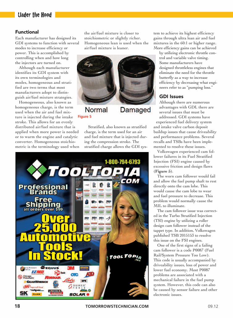
Volkswagen experienced cam fol-lower failures in its Fuel StratifiedInjection (FSI) engine caused byexcessive friction and design flaws(Figure 5).
The worn cam follower would failand allow the fuel pump shaft to restdirectly onto the cam lobe. Thiswould cause the cam lobe to wearand fuel pressure to decrease. Thisproblem would normally cause theMIL to illuminate.
The cam follower issue was correct-ed in the Turbo Stratified Injection(TSI) engine by utilizing a rollerdesign cam follower instead of thetappet type. In addition, Volkswagenpublished TSB 2015153 to resolvethis issue on the FSI engines.
One of the first signs of a failingcam follower is a code P0087 (FuelRail/System Pressure Too Low).This code is usually accompanied bydriveability issues, loss of power andlower fuel economy. Most P0087problems are associated with amechanical failure in the fuel pumpsystem. However, this code can alsobe caused by sensor failure and otherelectronic issues.
Under the Hood
Figure 5

TOMORROWSTECHNICIAN.COM 09.12
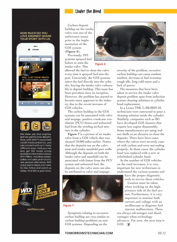
Carbon depositbuildup on the intakevalve was one of theunforeseen issuesprior to the imple-mentation of theGDI system (Figure 6).
Previously, PFIsystems sprayed fuelbefore or onto theintake valve. Thisallowed the fuel to clean the valveevery time it sprayed fuel into theport. Conversely, the GDI systemsinject the fuel directly into the cylin-der, leaving the intake valve vulnera-ble to deposit buildup. This issue hasbeen prevalent since its inception.However, the problem has started tobecome more apparent in the indus-try due to the recent increase ofGDI vehicles.
The carbon buildup in the GDIsystems can be associated with valveseal seepage, positive crankcase ven-tilation (PCV) fumes and unburnedfuel from the swirling air/fuel mix-ture in the cylinder.
Figure 7 is a picture of an intakevalve from a GDI vehicle that wascleaned 10,000 miles earlier. Noticethat the deposits are on the valvestem and intake manifold port walls.Although the deposits on both theintake valve and manifold can beassociated with fumes from the PCVsystem and unburned fuel, thedeposits on the valve stem can alsobe attributed to valve seal seepage.
Symptoms relating to excessivecarbon buildup are very similar tocarbon buildup problems on non-GDI systems. Depending on the
severity of the problem, excessivecarbon buildup can cause randommisfires, decrease in fuel economy,rough idle, long cold starts and alack of power.
The measures that have beentaken to service the intake valvedeposit problem span from inductionsystem cleaning solutions to cylinderhead replacement.
In a Lexus TSB, L-SB-0029-10,technicians were instructed to pour acleaning solution inside the cylinder.Similarly, companies such as BGhave developed GDI cleaners thatrequire less engine disassembly.Some manufacturers are using wal-nut shells as an abrasive to clean thedeposits. There have been caseswhere the valves were severely coat-ed with carbon and were not sealingproperly. In those cases, the cylinderhead was replaced with a new orrefurbished cylinder head.
As the number of GDI vehicleson the road increases, it is veryimportant for new technicians tounderstand the various systems and
have the proper diagnostictools to service these vehicles.
Caution must be takenwhen working on the high-pressure side of the fuel sys-tem. Furthermore, it is veryimportant to monitor bothcurrent and voltage with anoscilloscope to diagnose fuelinjector malfunctions. There
are always advantages and disad-vantages when technologyadvances. For now, the next step isGDI.
Under the Hood
Figure 6
Figure 7


22 09.12
In this article, we’ll take a look at brake and undercar service on theMazda line of cars and light trucks. Since this work is a mainstay formany shops, the nuts and bolts of this type of work should be routineto all but the newest techs like yourselves. With some of those folks
cutting their teeth in the shop doingthis kind of work, we’ll cover things
that will help the rookies whilereminding the more experiencedtechs of this fact: While brakeand chassis work can becomeroutine, good work habits arecritical for a successful jobfrom beginning to end.
Br35
Ba56
aking
d:Solving Mazda Noise Complaints Adapted from Bob Dowie’s article in


24 TOMORROWSTECHNICIAN.COM 09.12
Every job should startwith the customer inter-
view. When the appoint-ment is made, it’s impor-tant that some ques-tions that will helpensure a successful jobget answered. The first
question to ask is whythe customer thinks the
brakes need service. What isobvious to us is a mystery to
the customer so it’s importantthat we establish what it is that
has the customer concerned. Thereis nothing more disappointing to a
customer than to spend money on arepair and not have their concerns
addressed. And, with the brakes being the mostimportant safety system in a vehicle, you don’t want folksdriving for a week with the brakes metal to metal.
If you’re operating a successful shop, you are probablyalready focusing on preventive maintenance and all ofyour techs, as well your customers, are aware of the ben-efits of that practice. Your regular clients are expectingthat the brakes will be at least visually inspected whenev-er the car is in for service and it’s up to you not to disap-point them.
Anticipating and pointing out service that will be need-ed in the future isn’t selling as much as it is performing avaluable service. It is beneficial for both the shop and thecustomer to anticipate future services, allowing them totie up the car when it’s convenient for them, while youkeep the bays full with scheduled work.
Brake problems will present themselves in a couple ofways. The most common complaints are noise-related.Mazdas, like many other manufacturers, make use of thesimple and effective tab-type sensor that will contact therotor when the pads need to be replaced. The resulting,high-pitched squeaking noise has proven to be very effec-tive in getting drivers’ attention. That’s not to say that
drivers won’t ignore it and drive until the brakes aremaking that distinctive grinding noise that indicates thefriction material is gone and metal-to-metal contact istaking place. Of course, in that case, the car should beparked until repairs are made.
Many of the occasional, annoying noises that discbrakes make are a small trade-off for the braking performance delivered by the system. Oftentimes, justexplaining that to a customer goes a long way toward settling any concerns that something is wrong withhis/her brakes.
But, any noise that is more than occasional should beinvestigated. Some noise will be the result of rust on therotors, calipers, hardware or even the brake pads them-selves. Use only the best parts, replace questionable unitsand make sure that the brake hardware is in good condi-tion or new. This is particularly important with Mazda 3sand 6s that have some problems with the hardware con-tacting the rotors. There have been some tech bulletinsrelated to this issue so be sure to check your service info.Also make sure that all the metal-to-metal contact areasare lubed with the proper grease that’s designed to dothis tough job in a harsh environment.
Preliminary InspectionThe first step in any brake inspection should be a testdrive, as it’s always a good idea to confirm the customer’scomplaint. The test drive will also let you note any otherissues with the car that should be addressed while thebrake service is being performed.
Again, on the Mazda 3s, wheel bearing failures arefairly common and the noise will come on gradually andis often overlooked by the customer. If you’re going tohave the brakes apart, this is the time to take care of thewheel bearings. The same can be said for sway bar links.Oftentimes, just letting the customer know that the causeof that banging noise can be taken care of at a reasonablecost will motivate the repair. I think we all agree that it’smore efficient to know the noise is there before the car ison the lift. Of course, you will also be looking for rotorvibration/pulsation, a long pedal or pulling that would be
Undercover
Tell-Tale SIgNS: leaking calipers or wheel cylindersalways leave visual evidence, so inspect the brake hoses andif they need to be replaced, now is the time to take care ofit. If you suspect a sticking caliper, take the time to con-firm it. Pads that are seized in the brackets or frozen slid-ers will mimic a bad caliper, even though hydraulically thecaliper is fine.


TOMORROWSTECHNICIAN.COM 09.12
directly related to the brake system. The inspection continues back at
the shop and on the lift. It shouldn’ttake long to establish that the vehi-cle needs brake service, but beforeyou call to get authorization fromthe customer, spend a few minutesso you can provide an accurate esti-mate. I’ve never had a customerwho enjoys getting that surprisephone call that more problems havebeen found.
Spin and shake the wheels beforethey come off. Any excessive dragshould be noted and, it goes with-out saying, that any looseness in thesteering should be investigated andreported. The same goes forcracked CV boots or leaking struts.With the wheels off, it doesn’t takelong to get a good look at the padsand rotors. Read them for addition-al information, and look for signs ofoverheating or uneven wear indi-cating a sticking caliper or pads.
After the car has been inspect-ed and the job has been sold, it’stime to get to work. As I men-tioned earlier, brake work is rou-tine for the most part for most ofus, but it’s important that solidwork habits are used from thebeginning to the end of the job. Besure to open the bleeder valvesbefore the pistons are pushedbacked into the caliper.
With most cars today being
equipped with ABS, there is littletolerance for contaminated fluidbeing pushed back through the system and that sensitive modulatorunit. You are going to be bleedingand flushing the system as part ofthe service, so there is no time lostin this step. And, if the bleedercan’t be opened or needs to becleaned, it’s better to find out nowrather than after the caliper hasbeen serviced and new pads havebeen installed.
Questioning theCustomer
The most common brake-relatedvibration is that which occurswhile braking and is caused bydisc thickness variation. Ask yourcustomer some questions thatcould help ensure a quality job.When did you notice the problem,and was there any action that ledto the problem? Did you have anytire work done lately? If so, it’slikely you’ll find that the lug nuts
are unevenly tightened. To con-firm this condition, loosen
the lug nuts by hand.More often than not,the overtightenednuts will be obvious.
The biggest enemy of the rotor isheat. The rotor has a tough job ona system that’s in good shape, but itdoesn’t have a chance on a systemthat has excessive, heat-causing
Undercover
09.12 TOMORROW’S TECHNICIAN
drag. Take a good look at therotors as they’re removed for signsof overheating. It makes little senseto install fresh parts only to subjectthem to the same conditions. Itcould be that the last tech who didthe brakes didn’t get the caliperbrackets clean or missed a pointthat should have been lubed. Morelikely, the increased mileage hascaused a problem. Either way, ifit’s not corrected, your new rotorswill soon be in the same shape asthe ones you just took off.
This leads us to more discussionon work habits. Be certain that allthe areas where pad movementtakes place are cleaned and lubed.Don’t overlook the area under thetin pad brackets; rust buildup herewill result in tight-fitting pads. Alsobe sure the caliper slides areinspected, clean and lubed. This isimportant not only for smooth,quiet brake operation, but it is critical for the ABS to operate asexpected.
Being located in the Northeast,we see firsthand how the harshenvironment can be on the brakesystem. In extreme cases, you mayfind that it’s more cost effective toreplace the calipers rather thanspend the time required servicingthe originals.
With high-mileage vehicles, youcould be faced with a “brake pedalsometimes fades to the floor” com-plaint. Although it’s not a commoncomplaint on Mazdas, a little detec-tive work is required in such cases.If the pedal fades as the vehiclecomes to a stop, often in a situationwhere the pedal is being partially applied in anticipation of coming toa full stop, it’s a safe bet the mastercylinder is the culprit.
If, on the other hand, the condi-tion results from a long ride at
highway speeds, it’s likely thatexcessive drag is causing the fluidin the calipers to overheat, resultingin brake fade. When the brakescool, the pedal often will return towhat feels like normal to the cus-tomer. Many times, the customerwill report a burning smell and, inthe worse cases, will cause a severevibration. It takes a stuck caliper togenerate the degree of heat neededto cause these problems, and theycertainly should be checked closely.
You should be able to find theproblem wheels by inspecting therotors. If that much heat was gen-erated, the calipers, as well as therotors, will show the signs. If youcan duplicate the tight wheel,don’t be too quick to condemn thecaliper without cracking open thebleeder to be sure there’s no pres-sure in the line.
Delving into the JobIf pressure exists, backtrackthrough the hydraulic system untilthe restriction is found. It could bea collapsed brake hose acting as aone-way valve, or you may workyour way back to a contaminatedABS modulator. It’s always a goodpractice to replace any brake hosethat was subjected to extreme heat,even though it may look OK and
not leak. There is noway to know if theintegrity of the crimpswere comprised, so fora few dollars it’s better
to be safe than sorry. Mazda uses a hand-brake that is
incorporated into the rear caliper.They use a couple of systems toretract rear pistons. The later-model cars require the familiarmethod of turning the pistonclockwise while applying pressure,where others will have a plug onthe back side of the caliper thatprovides access for an Allenwrench to facilitate retracting thepiston, but be careful as youretract the piston.
Undercover
“brake pedal sometimesfades to the floor”

We know everyone doesn’t use his or her hand-brakeon a regular basis, and we also know that a mechanicaldevice doesn’t like to sit around not being used, only tosuddenly be forced into service. The same thing can besaid for the cables. If the hand-brake levers aren’t return-ing on the caliper, be sure that the cables aren’t binding.The complexity of the hand-brake does make the rearcalipers a little pricier, but I still like to replace them inpairs to maintain the balance of the brake system.
Finish off with a good bleed and flush of the hydraulicsystem, torque the wheels and the car should give thecustomer many miles of trouble-free braking.
Scanning for CluesWhen it comes to the ABS system, Mazdas have provento be very reliable, but that’s not to say they never havea problem. Codes can be retrieved on the early modelcars by grounding terminal 13 in the datalink -1 connec-tor that can be found under the hood. Install the jumperwith key off, and when you turn the key on, the ABS
lamp will be lit for three sec-onds before you get the
familiar flash codes —with the long flashes
representing tensand the shorts
being ones. Forexample, onelong flash
followed by a short flash represents a code 11 for aright front speed sensor circuit problem.
To clear the code, go through the same procedure waiting for the codes to be displayed. When the first codeis displayed a second time, hit the brakes 10 times at one-second intervals. If the code won’t clear, be sure thebrake light switch is working as expected. Be aware thatif the repair involved a wheel speed sensor or control unitrepair, the light will stay illuminated until the car is driven over six miles per hour.
With 2004 and newer models, you’ll need a scannerwith the capability of accessing the ABS system to
retrieve codes. Hopefully by now,your shop has made the investmentin the necessary equipment, asthere are plenty of affordableoptions available and it’s simply
foolish at this point to try and get by without the necessary tools.
As I mentioned earlier, we have been seeing somewheel bearing failures on the popular Mazda 3 models.The nuts and bolts of the replacement procedure shouldn’tpresent a challenge for most techs, but it’s important tokeep in mind that the bearings are directional and haveto be installed with the internal tone ring facing the ABSsensor.
Most bearings are colored-coded with the green sealbeing installed toward the sensor. Since the tone ring ismagnetic, you can confirm the proper direction by layinga clean piece of paper on the bearing and sprinkling someshavings from the brake lathe on the paper. It will beeasy to tell which side is magnetic and, needless to say,it’s critical that the shavings do not find their way intothe bearing.
Undercover
End stop
Contents page Reversed
28 TOMORROWSTECHNICIAN.COM 09.12
CheCk The ReCoRdS: as always, it neverhurts to check your service information.

ADVERTORIAL
CAREER OPPORTUNITIES
30 TOMORROWSTECHNICIAN.COM 09.12
Tomorrow’s Technician September Crossword
© Murray J acksonSolution at www.tomorrowstechnician.com
Across
1. Underbody components, collectively5. ‘60s gas slogan, “Put a ____ in your tank”8. Gear or compression trailer9. Dashboard channel (3,4)10. Toddler’s Tonka-truck terrain11. Under-dash area13. Clutch components14. Major engine castings17. Big-rig wheel count, often19. Gear teeth22. RWD car’s differential, slangily (4,3)23. Budget and Hertz rival24. OBD scan-tool data25. Alignment-rack measurement, maybe (4,3)
Down
1. Components returned for rebuilding2. Radio adjunct in auto glass, often3. Brake-system footwear4. Auto-tool brand since 1920 (4,2)5. Accelerator6. Dash dial7. Old-car noises, often12. Motorcyclists’ attire, often13. Post-1977 tire-sizing system (1,6)15. Antifreeze and water mixture16. Power-boosting exhaust manifold18. Brinks-truck occupant20. Oil-burner’s output21. Aftermarket auto-parts retailer
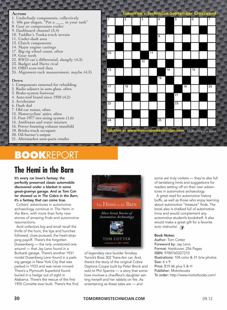
It’s every car lover’s fantasy: the perfectly preserved classic automobilediscovered under a blanket in somegreat-grannys garage. And as Tom Cot-ter showed us in The Cobra in the Barn,it’s a fantasy that can come true. Cotters’ adventures in automotivearchaeology continue in The Hemi inthe Barn, with more than forty new stories of amazing finds and automotiveresurrections. Avid collectors big and small recall thethrills of the hunt, the tips and hunchesfollowed, clues pursued, the heart-stop-ping payoff. There’s the forgottenDuesenberg — the only unrestored onearound — that Jay Leno found in aBurbank garage. There’s another 1931model Dusenberg Leno found in a park-ing garage in New York City that wasparked in 1933 and was never moved.There’s a Plymouth Superbird foundburied in a hedge out of sight inAlabama. There’s the rescue of the first1955 Corvette ever built. There’s the find
of legendary race builder SmokeyYunick’s Boss 302 Trans-Am car. And,there’s the story of the original CobraDaytona Coupe built by Peter Brock andsold to Phil Spectre — a story that some-how involves a chauffeur’s daughter set-ting herself and her rabbits on fire. Asentertaining as these tales are — and
some are truly corkers — they’re also fullof tantalizing hints and suggestions forreaders setting off on their own adven-tures in automotive archaeology. A great read for automotive historybuffs, as well as those who enjoy learningabout automotive “treasure” finds. Thebook also is chalked full of automotivetrivia and would complement any automotive student’s bookshelf. It alsowould make a great gift for a favoriteauto instructor.
Book Notes:Author: Tom CotterForeword by: Jay LenoFormat: Hardcover, 256 PagesISBN: 9780760327210Illustrations: 104 color & 31 b/w photosSize: 6 x 9Price: $19.46 plus S & HPublisher: Motorbooks To order: http://www.motorbooks.com/
BOOKREPORT
The Hemi in the Barn
09.12 TOMORROW’S TECHNICIAN 31
• DO NOT drop or use an oxygen sensor that hasbeen dropped as this may have caused shock dam-age to the ceramic element;
• DO NOT use any compounds on or around thesensor unless labeled as oxygen sensor friendlyproducts;
• DO NOT use an impact wrench or convention-al socket type wrench to install the sensor;
• DO NOT allow the sensor or lead wire to touch
the exhaust manifold or any other hot component;• DO NOT expose this product to water, oil,
windshield cleaner, anti-corrosion oil, grease, terminal cleaner, etc.;
• DO NOT use leaded fuels, silicone or metal-based additives; and
• DO NOT store under high humidity conditions.
Sourc e : NTK O xygen Sensors
TechTips
02 No-Nos: Proper Handling Tips for Oxygen Sensors
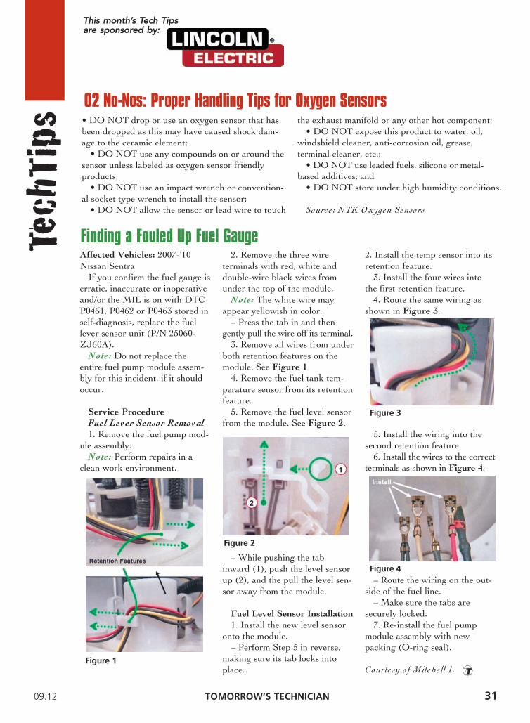
Affected Vehicles: 2007-’10Nissan Sentra
If you confirm the fuel gauge iserratic, inaccurate or inoperativeand/or the MIL is on with DTCP0461, P0462 or P0463 stored inself-diagnosis, replace the fuellever sensor unit (P/N 25060-ZJ60A).
Note: Do not replace theentire fuel pump module assem-bly for this incident, if it shouldoccur.
Service Procedure
Fuel Lev er Sensor Remov al
1. Remove the fuel pump mod-ule assembly.
Note: Perform repairs in aclean work environment.
2. Remove the three wire terminals with red, white anddouble-wire black wires fromunder the top of the module.
Note: The white wire mayappear yellowish in color.
– Press the tab in and thengently pull the wire off its terminal.
3. Remove all wires from underboth retention features on themodule. See Figure 1
4. Remove the fuel tank tem-perature sensor from its retention feature.
5. Remove the fuel level sensorfrom the module. See Figure 2.
– While pushing the tabinward (1), push the level sensorup (2), and the pull the level sen-sor away from the module.
Fuel Level Sensor Installation
1. Install the new level sensoronto the module.
– Perform Step 5 in reverse,making sure its tab locks intoplace.
2. Install the temp sensor into itsretention feature.
3. Install the four wires intothe first retention feature.
4. Route the same wiring asshown in Figure 3.
5. Install the wiring into thesecond retention feature.
6. Install the wires to the correctterminals as shown in Figure 4.
– Route the wiring on the out-side of the fuel line.
– Make sure the tabs aresecurely locked.
7. Re-install the fuel pumpmodule assembly with new packing (O-ring seal).
Courte sy o f Mitche ll 1.
Finding a Fouled Up Fuel Gauge
Figure 1
Figure 2
Figure 3
Figure 4
This month’s Tech Tipsare sponsored by:
32 TOMORROWSTECHNICIAN.COM 09.12
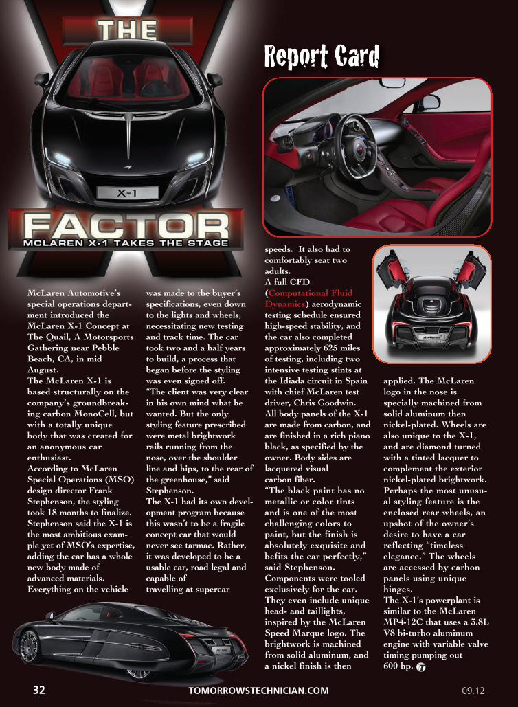
McLaren Automotive’s
special operations depart-
ment introduced the
McLaren X-1 Concept at
The Quail, A Motorsports
Gathering near Pebble
Beach, CA, in mid
August.
The McLaren X-1 is
based structurally on the
company’s groundbreak-
ing carbon MonoCell, but
with a totally unique
body that was created for
an anonymous car
enthusiast.
According to McLaren
Special Operations (MSO)
design director Frank
Stephenson, the styling
took 18 months to finalize.
Stephenson said the X-1 is
the most ambitious exam-
ple yet of MSO’s expertise,
adding the car has a whole
new body made of
advanced materials.
Everything on the vehicle
was made to the buyer’s
specifications, even down
to the lights and wheels,
necessitating new testing
and track time. The car
took two and a half years
to build, a process that
began before the styling
was even signed off.
“The client was very clear
in his own mind what he
wanted. But the only
styling feature prescribed
were metal brightwork
rails running from the
nose, over the shoulder
line and hips, to the rear of
the greenhouse,” said
Stephenson.
The X-1 had its own devel-
opment program because
this wasn’t to be a fragile
concept car that would
never see tarmac. Rather,
it was developed to be a
usable car, road legal and
capable of
travelling at supercar
speeds. It also had to
comfortably seat two
adults.
A full CFD
(Computational Fluid
Dynamics) aerodynamic
testing schedule ensured
high-speed stability, and
the car also completed
approximately 625 miles
of testing, including two
intensive testing stints at
the Idiada circuit in Spain
with chief McLaren test
driver, Chris Goodwin.
All body panels of the X-1
are made from carbon, and
are finished in a rich piano
black, as specified by the
owner. Body sides are
lacquered visual
carbon fiber.
“The black paint has no
metallic or color tints
and is one of the most
challenging colors to
paint, but the finish is
absolutely exquisite and
befits the car perfectly,”
said Stephenson.
Components were tooled
exclusively for the car.
They even include unique
head- and taillights,
inspired by the McLaren
Speed Marque logo. The
brightwork is machined
from solid aluminum, and
a nickel finish is then
applied. The McLaren
logo in the nose is
specially machined from
solid aluminum then
nickel-plated. Wheels are
also unique to the X-1,
and are diamond turned
with a tinted lacquer to
complement the exterior
nickel-plated brightwork.
Perhaps the most unusu-
al styling feature is the
enclosed rear wheels, an
upshot of the owner’s
desire to have a car
reflecting “timeless
elegance.” The wheels
are accessed by carbon
panels using unique
hinges.
The X-1’s powerplant is
similar to the McLaren
MP4-12C that uses a 3.8L
V8 bi-turbo aluminum
engine with variable valve
timing pumping out
600 hp.