Tomorrow’s Data Centre, Today
36
Tomorrow’s Data Centre, Today Evolution of DC Cabling Standards
-
Upload
panduit -
Category
Technology
-
view
552 -
download
0
Transcript of Tomorrow’s Data Centre, Today

Tomorrow’s Data Centre, Today
Evolution of DC Cabling Standards

2
AGENDA
• Bandwidth Drivers
• Value of the Physical Layer
• Standards and Roadmaps• Ethernet and FC
• Evolution of Short Reach Cabling
• Extended Value and Relevance of PanMPO
• Beyond 100G
• Wrap up

• Develop transport systems• Enabling fast, effective and efficient journey ($’s)
• Ensuring road safety (reduce risk of failure/downtime)
• Provision for future capacity/bandwidth• Growth drivers, trends, standards & roadmaps.
What do YOU do?

4
BANDWIDTH DRIVER EXAMPLE

5
A word on CHANGE
>145
Years
IBM and ARM
7Bn world population (today)
Equivalent to circa 23 per person
“200Bn connected devices by 2020”
- Intel Corp
“Everything that can be invented has
been invented”Charles H. Duell, Commissioner, US Patent Office, 1899
“640K ought to be enough for anybody”Bill Gates, Chairman, Microsoft, 1981
Patented in 1870

6
Physical Layer – Value Recap
• DC Managers <CAP-ex, <Op-ex and >ROI• Highly dense, reliable & scaleable
• Bring services on-line quickly
• Performance certainty
• Next generation ready• Change is happening at an unprecedented rate

7
.. every connector counts
Managed DensityBLOOPER AWARD 2015
Physical layer represents __ % of
project spend
___% downtime is attributed to physical
layer
Over 91% of *DC’s experience
unplanned outage in the first 2 years
The *physical layer is circa 40% more
valuable compared to 3 years ago
59- Gartner Group
5
*Ponemon Institute/Emerson - Jan 2014: A study on 584 datacenter’s

8
Evolution of Short Reach Technologies

9
Pathway to 40G, 100G…and beyond

10
Market Application & Forecast
• DC investment - >5 ROI is typical- Pathway to 100G is ‘top of mind’
Eth
ern
et
Fore
cast

11
Published standards as a Focus40/100G – Short Reach
Twisted Pair Structured
Cabling
Direct Attach Copper Products
Fibre
Category 8 /Class 8.I and 8.2
QSFP+ QSFP28 OM3 OM4
Highest Data Rate
40 Gig 40 Gig 100 Gig 40/100 Gig 40/100 Gig
IEEE Standard 802.3bq 802.3ba 802.3bj 802.3ba 802.3ba
Reach < 30m (TBD) Passive: 7m Passive: 5m 100m 150m
Migration path 10G, 25G & 40G – 40G & 100G 40G & 100G 40G & 100G
Cable patching 2 connector channel Point-to-point Point-to-point Structured Structured
Form Factor RJ45 (TBD) QSFP QSFPCFP, QSFP(40G), + Others
CFP, QSFP(40G), + Others
Published Standard
Target 2016
?
*2 connectors in the channel

12
Data Rate – IEEE/FC Roadmap

13
Published Standards - IEEE 802.3 Fibre Connector Interfaces
802.3 Media Device Interface (MDI)**IEEE P802.3bm approved May 10, 2015

14
Understanding MPORe-Cap

15
Remember the four P’s
PanMPO™- standards compliant MPO + additional features benefits
Performance
Polarity
Pins
- maintain transmission path from Tx to Rx. Standard covers Method A, B and C.
– mates male (pinned) connector to female (non-pinned) connector.
– consider both current and future insertion Loss (IL) and reach requirements

16
Male Alignment Pins
Key
12 fibre MTP/MPO Connector
Method A - Adapter
Keyway-up Male (Pins)
• Maintaining polarity with LC
connectors was simple
• Pins (Gender)
• Precisely align the mating connectors
• Creates male/female pair
• Polarity - ANSI/TIA-568-C.0
• Keyed/Maintains orientation
• Method A, B and C
• Complies to MPO connector standards
- IEC-61754-7 and EIA/TIA-604-5 (FOCIS 5).
Keyway-down female (without Pins)
MPO = standards based reference for the connectorPanMPO = Trade name – Panduit
MTP = trade name - USCONEC
Polarity and Pins

17
Where did the budget go?
Data RateDesignation
Example Fibre typeNumber of
fibersMaximum link length
(in meters) Channel IL Max. (dB)
10-Gbit Ethernet 10GBase-SR OM3 2 300 2.6
40-Gbit Ethernet 40GBase-SR4 OM3 8 100 1.9
40-Gbit Ethernet 40GBase-SR4 OM4 8 150 *1.5
100-Gbit Ethernet 100GBase-SR10 OM3 20 100 1.9
100-Gbit Ethernet 100GBase-SR10 OM4 20 150 *1.5
6
4.5
2.6
1.9 1.91.5 1.5
100Mb's 1G 10G 40G 100G
Channel Loss (IL) allowed for 850nm Ethernet Transmission @ Maximum Reach – per IEEE Standard
OM3 IL dB
OM4 IL dB
*1.0dB of connector/splice loss
CONSIDER HEADROOM
for
FUTURE DATA RATES

18
Extend your REACH
40GBASE-SR4/100GBASE-SR10
Panduit connector performance grades
Ethernet - reach examples (Panduit)

19
• Intuitive 1:1 Migration path• 40G/100G (*4x25G)
o No additional ‘RU’ rack space required
• 128G Fibre Channel – MPO is a strong contender• †4 x 32G lanes – standard is under development
4x25G 4x25G
40G, 100G & †128G FC
40G, 100G& †128G FC Note. Change to male (pined)
recommended for 40/100G
*
10G/25G?NB. or Cisco BiDi 40G
10G, 25G?or Cisco BiDi 40G
Migration Example
20
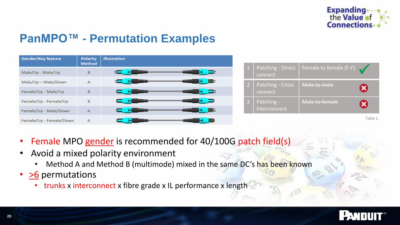
PanMPO™ - Permutation Examples
Table 1.
1 Patching - Direct connect
Female to female (F-F)
2 Patching - Cross connect
Male to male
3 Patching -Interconnect
Male to female
• Female MPO gender is recommended for 40/100G patch field(s)• Avoid a mixed polarity environment
• Method A and Method B (multimode) mixed in the same DC’s has been known
• >6 permutations• trunks x interconnect x fibre grade x IL performance x length

21
Testing 40G
MPO Channels
Remove uncertainty
Increase ‘time to revenue’
Be on budget and on time

22
Testing - Basics
• IEC 61282-15 (draft only) pending publication - Testing multi-fiber optic cable plant terminated with MPO connectors
• Purpose built 40G testers from leading brands - Unidirectional testing (first window - 850nm)
- Polarity/miss-wire checking
- Fixed gender test heads – testing all 12 fibers at once
• Cleaning challenges - Inspect, clean, inspect process (ICI) - best practice
- Debris migrates towards pins and is a challenge to clean effectively- PanMPO eliminates the need for multiple styles of MPO cleaner

23
Fast FACT
PanMPO *uniquely facilitates fast & effective field
testing of both male and female links (trunks) in
accordance with the ‘one jumper’ reference method
*no need to change manufacturers test equipment
• The ‘single Jumper reference’ is recommended in international standards for testing cabling links.- this method provides the highest level of test certainty.
- IEC 61280-4-1 (Method 1)- ANSI/TIA 568-C (Method B)
25
Beyond
100G
26
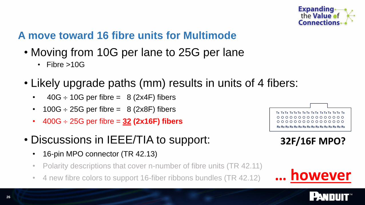
A move toward 16 fibre units for Multimode
• Moving from 10G per lane to 25G per lane• Fibre >10G
• Likely upgrade paths (mm) results in units of 4 fibers:• 40G 10G per fibre = 8 (2x4F) fibers
• 100G 25G per fibre = 8 (2x8F) fibers
• 400G 25G per fibre = 32 (2x16F) fibers
• Discussions in IEEE/TIA to support: • 16-pin MPO connector (TR 42.13)
• Polarity descriptions that cover n-number of fibre units (TR 42.11)
• 4 new fibre colors to support 16-fiber ribbons bundles (TR 42.12)
32F/16F MPO?
… however

27
Data
RatePMD
OM3
50 m
OM4
50 mSM
400G(in process)
400GBASE-SR16 (16f x 25G) At least 100m N/A
400Gfuture? 4f x 4 x 25G At least 100m N/A
400G
400GBASE-DR4 (4f x 100G)
400GBASE-FR8 (8 x 50G)
400GBASE-LR8 (8 x 50G) N/A
500 m
2 km
10 km
400G Fibre Options and Reach examples
Note: Todays SM transceivers >2x cap-ex of MM, also higher power.

28
Multiple Wavelengths Transmitted on Same Multimode Fibre
4 VCSELs850-950nm MUX DEMUX
4 Detectors850-950nm
Fiber Core
• Cost effective MM VSCEL Technology• compared to traditional laser driven SM transceivers
• Supported by leading multimode glass developers
CWDM/SWDM (Course/Short Wavelength Division Multiplexing)

29
CWDM/SWDM (Course/Short Wavelength Division Multiplexing)
• 400Gb/s transmission using 8 fibre’s
• Overcome cable management and density challenges
• Use existing MM MPO cable plant 40G/100G to 400G migration.
• No additional RU space/fibre required
• 100Gb/s over 2 x multimode fibres
• LC Duplex (MM)
WideBand Multimode Fibre
4x4 @25G
(400G Rx)
4x4 @25G
(400G Tx)

30
Potential Future Application - Example
LC10G (today)
40G25G50G
100G...also up to 128 FC?
• 400G to 4x100G Wideband Harness• Effective distribution between leaf/spine. • Lower Cap-ex , 400G (running in 4x100G Mode)
• lower power, lower cost compared to purchasing multiple 100G transceivers?
• ROI, up to 5 generations of switch refreshes!!!
Wideband ‘harness’
SPINE
LEAF
4x4 @25G
(400G Rx)
4x4 @25G
(400G Tx)

31
WideBand MMF - Highlights
• 4x the bandwidth of OM4 fibre
• Supports legacy 850nm OM4 applications
• Support for duplex 100Gb/s technology Finistar, Juniper, Huawei, Dell, Lumentum
• Will support 8 fibre 400Gb/s technology
• Panduit is LEADING the standards group for WBMMF • Brett Lane (Panduit) is chairman of TIA Joint Task Group to develop the next generation
multimode fiber (Wide Band Multimode Fiber) TIA TR-42.11 and TR-42.12 to develop specification for Wide-Band Multimode Fibre
• Participation from diverse group, including active device and systems vendors
• Goal for TIA specification be mirrored by IEC 86A

32
RE-CAP
• MPO cabling has increased relevance & lifecycle (>ROI)- Enable a 1:1 migration path to 40G, 100G and now, scope for 400G
With existing horizontal cabling + follow best practice.
• Raise performance certainty with PanMPO- Unique test methodology guarantees highest ‘certainty’
• On-time on-Budget - MAC’s are simple/more reliable making both primary install and future upgrades faster
• Connector cleaning and test efficiencies
• Reduce capital expenseLower inventory & re-use existing infrastructure when migrating with PanMPO
33
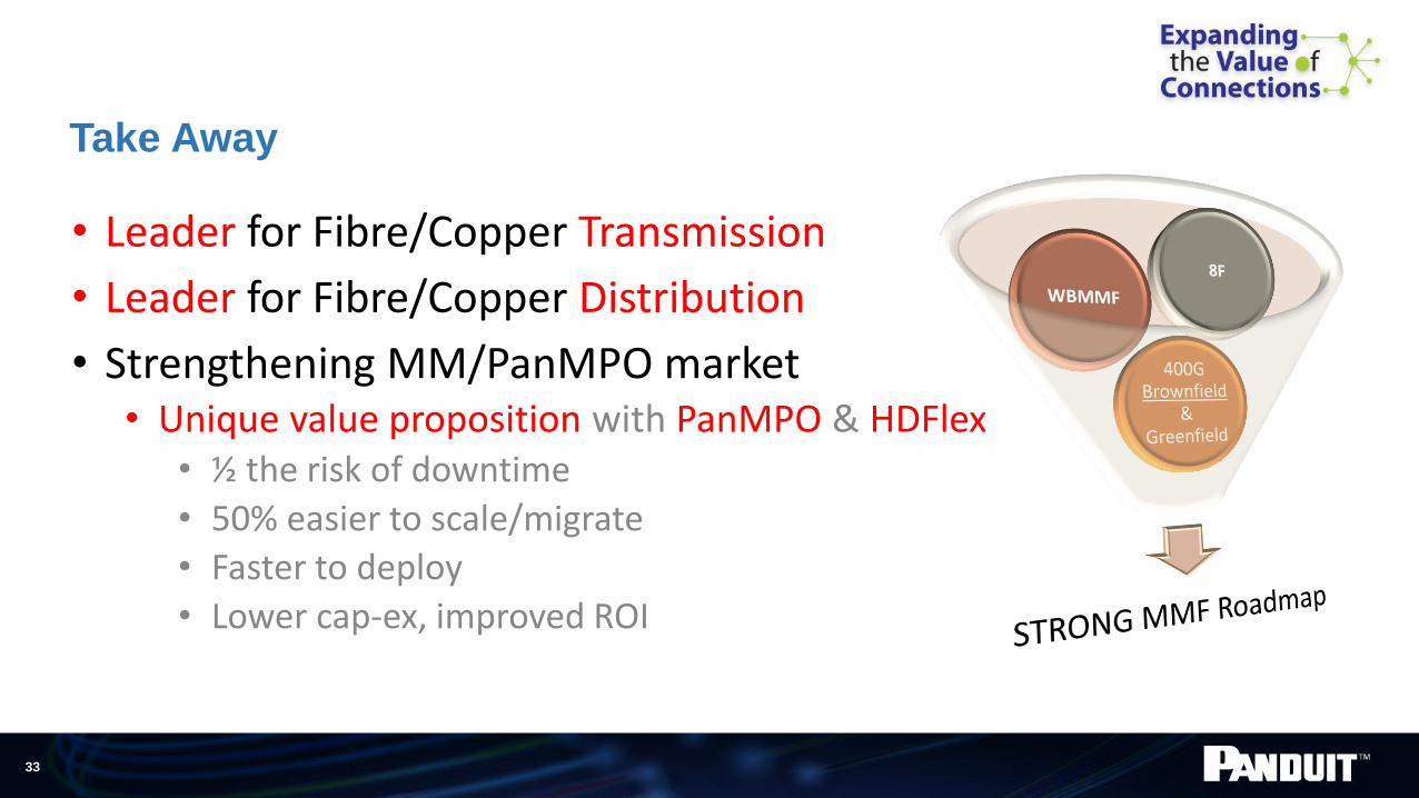
Take Away
• Leader for Fibre/Copper Transmission
• Leader for Fibre/Copper Distribution
• Strengthening MM/PanMPO market• Unique value proposition with PanMPO & HDFlex
• ½ the risk of downtime
• 50% easier to scale/migrate
• Faster to deploy
• Lower cap-ex, improved ROI

34
Thank you very much
for your attention – Questions?
Stephen Morris
Snr Product Manager
DC Connectivity Solutions
Email: [email protected]
For more info can be found here:www.Panduit.com/PanMPOwww.Panduit.com/HDFLEXhttp://www.ethernetalliance.org/http://fibrechannel.org/alliance-partners.html

35
Appendix

Why 25G Ethernet?
• 25G CFI July 2014• Twinax and Optical
• Focus today is on cloud
• Next gen equipment is optimized for 25G signaling
• Considered a logical migration path to 100G
25G = Optimal Density & Bandwidth

25Gig Twin-ax Roadmap
• 100G switch to 4x 25G servers- QSFP28 to 4 x SFP28
- 5m max.
• 25G switch to 25G server- SFP28 to SFP28
- 5m max.
• 100Gig switch to 100G server- 100G QSFP+
- 5m max
… also expect 25G optical & 25G CAT8