Tomingley Gold Project Surface Water Assessment · Gold Project Surface Water Assessment ......
128
ABN: 35 000 689 216 ABN: 35 000 689 216 Tomingley Gold Project Surface Water Assessment September 2011 Prepared by SEEC Specialist Consultant Studies Compendium Volume 1, Part 2
Transcript of Tomingley Gold Project Surface Water Assessment · Gold Project Surface Water Assessment ......

ABN: 35 000 689 216
ABN: 35 000 689 216
Tomingley Gold Project
Surface Water Assessment
September 2011
Prepared by
SEEC
Specialist Consultant Studies Compendium
Volume 1, Part 2

This page has intentionally been left blank

SPECIALIST CONSULTANT STUDIES 2 - 1 ALKANE RESOURCES LTD Part 2: Surface Water Assessment Tomingley Gold Project Report No. 616/06
SEEC
Tomingley Gold Project
Surface Water Assessment
Prepared for: R.W. Corkery & Co. Pty Limited 62 Hill Street ORANGE NSW 2800 Tel: 02 6362 5411 Fax: 02 6361 3612 Email: [email protected]
On behalf of: Alkane Resources Ltd 65 Burswood Road
BURSWOOD WA 6100 Tel: (08) 93289411 Fax: (08) 9227 8178 Email: [email protected]
Prepared by: SEEC PO Box 1098 BOWRAL NSW 2576 Tel: 02 4862 1633 Fax: 02 4862 3088 Email: [email protected]
September, 2011

ALKANE RESOURCES LTD 2 - 2 SPECIALIST CONSULTANT STUDIES Tomingley Gold Project Part 2: Surface Water Assessment Report No. 616/06
SEEC
COPYRIGHT
© SEEC, 2011 and
© Alkane Resources Ltd, 2011
All intellectual property and copyright reserved.
Apart from any fair dealing for the purpose of private study, research, criticism or review, as permitted under the Copyright Act, 1968, no part of this report may be reproduced, transmitted, stored in a retrieval system or adapted in any form or by any means (electronic, mechanical, photocopying, recording or otherwise) without written permission. Enquiries should be addressed to SEEC.

SPECIALIST CONSULTANT STUDIES 2 - 3 ALKANE RESOURCES LTD Part 2: Surface Water Assessment Tomingley Gold Project Report No. 616/06
SEEC
CONTENTS Page
EXECUTIVE SUMMARY ......................................................................................................................................... 2-7
1 INTRODUCTION ............................................................................................................................................. 2-9
2 PROJECT OVERVIEW .................................................................................................................................... 2-9
2.1 Tomingley Gold Project Site .............................................................................................................. 2-9
2.2 Overview of the Project .................................................................................................................... 2-14
3 STUDY AREA ............................................................................................................................................... 2-15
4 ENVIRONMENTAL SETTING ....................................................................................................................... 2-15
4.1 TOPOGRAPHY ............................................................................................................................... 2-15
4.2 LAND USE ....................................................................................................................................... 2-18 4.2.1 Mine Site ......................................................................................................................... 2-18 4.2.2 Surrounding Lands .......................................................................................................... 2-18
4.3 SOILS .............................................................................................................................................. 2-18
4.4 DRAINAGE ...................................................................................................................................... 2-19 4.4.1 Regional Drainage .......................................................................................................... 2-19 4.4.2 Local Water Courses and Dams ..................................................................................... 2-19 4.4.3 Catchment Areas and Boundaries .................................................................................. 2-21
4.4.3.1 Gundong Creek – Catchment 1 ................................................................... 2-21 4.4.3.2 Drainage Lines A, B, C – Catchment 2........................................................ 2-21 4.4.3.3 Drainage Line D – Catchment 3 .................................................................. 2-21 4.4.3.4 Catchment 4 ................................................................................................ 2-22
4.5 FLOODING ...................................................................................................................................... 2-22
4.6 GROUNDWATER ............................................................................................................................ 2-22
4.7 VEGETATION .................................................................................................................................. 2-23
4.8 CLIMATE ......................................................................................................................................... 2-23 4.8.1 Rainfall ............................................................................................................................ 2-23 4.8.2 Evaporation ..................................................................................................................... 2-24 4.8.3 Rainfall to Evaporation Comparison ................................................................................ 2-25
5 SURFACE WATER ASSESSMENT .............................................................................................................. 2-26
5.1 PEAK FLOWS ................................................................................................................................. 2-26 5.1.1 Background and Modelling Procedure ............................................................................ 2-26 5.1.2 Peak Flow Run-off Results ............................................................................................. 2-28
5.2 FLOOD MODELLING ...................................................................................................................... 2-29 5.2.1 Introduction ..................................................................................................................... 2-29 5.2.2 Catchment 1 Flood Heights ............................................................................................ 2-30 5.2.3 Catchment 2 Flood Heights ............................................................................................ 2-33
5.3 SURFACE WATER QUALITY AND VOLUMES .............................................................................. 2-33 5.3.1 Background and Introduction .......................................................................................... 2-33 5.3.2 Modelling Area ................................................................................................................ 2-33 5.3.3 Climate Data for MUSIC Modelling ................................................................................. 2-34 5.3.4 Pre-Development Modelling Calibration and Setup ........................................................ 2-34 5.3.5 Operational-Stage Modelling Calibration and Setup ....................................................... 2-35 5.3.6 Results of MUSIC Modelling ........................................................................................... 2-37
5.4 HARVESTABLE RIGHT ................................................................................................................... 2-37
5.5 WATER SAMPLING AND TESTING ............................................................................................... 2-38
5.6 WATER BALANCE .......................................................................................................................... 2-39 5.6.1 Water Demand ................................................................................................................ 2-39

ALKANE RESOURCES LTD 2 - 4 SPECIALIST CONSULTANT STUDIES Tomingley Gold Project Part 2: Surface Water Assessment Report No. 616/06
SEEC
CONTENTS Page
5.6.1.1 Introduction................................................................................................. 2-39 5.6.1.2 Operational Water Requirements ............................................................... 2-39 5.6.1.3 Dust Suppression and Revegetation Water Requirements ........................ 2-40 5.6.1.4 Potable / Ablution Water Requirements ..................................................... 2-40
5.6.2 Water Supply ................................................................................................................. 2-40 5.6.3 Water Security ............................................................................................................... 2-40
6 IMPACT ASSESSMENT............................................................................................................................... 2-41
6.1 INTRODUCTION ............................................................................................................................ 2-41
6.2 PEAK FLOWS................................................................................................................................. 2-42
6.3 FLOODING AND ACCESS ............................................................................................................. 2-43 6.3.1 Flood Heights ................................................................................................................. 2-43 6.3.2 Proposed Main Site Access Road .................................................................................. 2-43 6.3.3 Newell Highway Underpass ........................................................................................... 2-44
6.4 SURFACE WATER QUALITY AND VOLUMES.............................................................................. 2-44
6.5 DIVERSION OF WATER BETWEEN CATCHMENTS .................................................................... 2-44
6.6 ONSITE EFFLUENT MANAGEMENT ............................................................................................ 2-45
6.7 WATER QUALITY AND RIVER FLOW OBJECTIVES .................................................................... 2-45 6.7.1 Water Quality Objectives – Bogan River ........................................................................ 2-45 6.7.2 River Flow Objectives – Bogan River ............................................................................. 2-45
7 WATER MANAGEMENT STRATEGY ......................................................................................................... 2-50
7.1 INTRODUCTION ............................................................................................................................ 2-50
7.2 OBJECTIVES.................................................................................................................................. 2-50
7.3 Recommendations .......................................................................................................................... 2-50 7.3.1 Sediment Basins ............................................................................................................ 2-50 7.3.2 Surface Water Diversions and Bunds ............................................................................ 2-52 7.3.3 Drop-Down Structures.................................................................................................... 2-52 7.3.4 Mine Site Effluent Management ..................................................................................... 2-53 7.3.5 Mine Site Access ........................................................................................................... 2-53
7.3.5.1 Gundong Creek Crossing ........................................................................... 2-53 7.3.5.2 Tomingley West Road Intersection ............................................................. 2-54
7.3.6 Newell Highway Underpass ........................................................................................... 2-54 7.3.7 Water Harvesting and Dust Suppression ....................................................................... 2-54 7.3.8 Existing Farm Dams ....................................................................................................... 2-54 7.3.9 Residue Storage ............................................................................................................ 2-54
7.4 WATER QUALITY MONITORING .................................................................................................. 2-55
7.5 WATER MANAGEMENT STRATEGY MONITORING AND MODIFICATION ................................ 2-55
8 REFERENCES ............................................................................................................................................. 2-56

SPECIALIST CONSULTANT STUDIES 2 - 5 ALKANE RESOURCES LTD Part 2: Surface Water Assessment Tomingley Gold Project Report No. 616/06
SEEC
CONTENTS Page
APPENDICES Please note the Appendices are provided in full and in colour on the Project CD
Appendix 1 IFD Chart for Tomingley ................................................................................................................... 59 Appendix 2 Existing Culvert Design Check ......................................................................................................... 63 Appendix 3 DRAINS Output Files and Cross-Sections ....................................................................................... 67 Appendix 4 RATES Modelling Outputs ............................................................................................................... 77 Appendix 5 Sediment Basin Sizing Spreadsheet ................................................................................................ 81 Appendix 6 Plans and HEC-RAS Output data for Proposed Gundong Creek Crossing ..................................... 85 Appendix 7 New South Wales Office of Water Requirements for Controlled Activities ....................................... 93 Appendix 8 Water Sampling Results .................................................................................................................. 97 Appendix 9 Director-General’s Requirements ................................................................................................... 117 FIGURES Please note all Figures are provided in colour on the Project CD
Figure 1 Locality Plan .................................................................................................................................. 2-10 Figure 2 Mine Site Layout ........................................................................................................................... 2-11 Figure 3 Tomingley – Narrabri Water Pipeline Route (0 to 22km) ............................................................... 2-12 Figure 4 Tomingley – Narrabri Water Pipeline Route (22km to 46km) ........................................................ 2-13 Figure 5 Mine Site and Surrounding Catchments within the Study Area ..................................................... 2-16 Figure 6 Regional Setting, Topography and Drainage ................................................................................ 2-17 Figure 7 Mine Site Topography and Drainage ............................................................................................ 2-20 Figure 8 Monthly rainfall analysis for Peak Hill Post Office Station 050031 ................................................ 2-24 Figure 9 Mean Daily Evaporation by Month ................................................................................................ 2-25 Figure 10 Mean Monthly Rainfall vs Mean Monthly Evaporation .................................................................. 2-26 Figure 11 XP-RAFTS Model of Gundong Creek (Catchment 1) .................................................................... 2-26 Figure 12 Detail of XP-RAFTS Model Across the Actual Mine Site ............................................................... 2-27 Figure 13 Proposed Water Control Structures on the Mine Site ................................................................... 2-31 Figure 14 Indicative Bund and Surface Water Control Structure Design....................................................... 2-32 Figure 15 Time-series Chart for One-Hourly Rainfall and PET as Used in MUSIC Models .......................... 2-35
TABLES Table 1 Mean Monthly Rainfall and Evaporation ....................................................................................... 2-25 Table 2 Input Data for Peak Flow Calculations .......................................................................................... 2-28 Table 3 Peak Flow Calculations for Each Catchment ................................................................................ 2-29 Table 4 Modelled 100-year Flood Heights in Catchment 1 ........................................................................ 2-30 Table 5 One-hourly Rainfall and PET statistics used in MUSIC models .................................................... 2-34 Table 6 Calibration of Pervious Area Properties for MUSIC Source Nodes (from Macleod, 2008) ............ 2-35 Table 7 MUSIC Stormwater Pollutant Input Parameters for Operational Areas of the Mine Site ............... 2-36 Table 8 Results of MUSIC Modelling (Mean Annual Loads) ...................................................................... 2-37 Table 9 Annual Water Demand and Assessment against Pipeline Supply Only ........................................ 2-39 Table 10 Results of RATES Modelling - Water Demand Met by Harvestable Right Storages ..................... 2-41 Table 11 Analysis of Peak Flow Changes Before and After Mine Establishment (Derived from Table 3) .... 2-42 Table 12 Assessment of the Project Against the Water Quality Objectives for the Bogan River ................. 2-46 Table 13 Assessment of the Project Against the River Flow Objectives for the Bogan River ...................... 2-48 Table 14 Sediment Basin Sizes ................................................................................................................... 2-51

ALKANE RESOURCES LTD 2 - 6 SPECIALIST CONSULTANT STUDIES Tomingley Gold Project Part 2: Surface Water Assessment Report No. 616/06
SEEC
This page has intentionally been left blank
SPECIALIST CONSULTANT STUDIES 2 - 7 ALKANE RESOURCES LTD Part 2: Surface Water Assessment Tomingley Gold Project Report No. 616/06
SEEC
EXECUTIVE SUMMARY
This report constitutes a surface water assessment for the proposed Tomingley Gold Project (“the Project”). The Project, an open cut and underground mining development to be located immediately south of the village of Tomingley, would be operated by Alkane Resources Ltd. This assessment includes a review of the existing surface water conditions and hydrology at the site of the proposed mining, processing and ancillary operations (“the Mine Site”) and within its local context. It also includes an assessment of the potential impacts of the Project, on surface water conditions and a water management strategy to mitigate or address these impacts, including a site water balance. The proposed Mine Site occupies part of four separate catchments, all of which ultimately drain into Gundong Creek and, eventually, the Bogan River. To mitigate the potential for the Project to impact on surface water flows, volumes and quality, a system of surface water management structures would be included within the Mine Site. These would include five sediment basins to capture and treat sediment-laden runoff, two dewatering ponds for the storage of runoff and groundwater seepage accumulating in the open cuts, bunds to mitigate flood risks, and diversion structures to minimise the risk of excessive run-on into the Mine Site. Surface water management structures have been positioned to ensure that no water is diverted into or out of any natural catchment at the Mine Site boundary. Peak flow and surface water runoff volume modelling shows that there would be minimal impact to downstream users and/or the riparian ecology of the local drainage lines. Flood modelling shows that increases in local flood levels would be minimal and are unlikely to negatively impact any off site or downstream landholders. A water balance of the Project Site has been included in this report to illustrate the distribution of water and to show how the anticipated water demands for the Project would be met. Water balance modelling indicates that the overall demand can be met, even at maximum production, from a combination of harvestable right storages and a bore-fed pipeline.

ALKANE RESOURCES LTD 2 - 8 SPECIALIST CONSULTANT STUDIES Tomingley Gold Project Part 2: Surface Water Assessment Report No. 616/06
SEEC
This page has intentionally been left blank

SPECIALIST CONSULTANT STUDIES 2 - 9 ALKANE RESOURCES LTD Part 2: Surface Water Assessment Tomingley Gold Project Report No. 616/06
SEEC
1 INTRODUCTION
SEEC have been commissioned by Alkane Resources Ltd to prepare a Surface Water Assessment for the proposed Tomingley Gold Project (“the Project”), an open cut and underground mining development to be located immediately south of the village of Tomingley in the NSW Central West (see Figure 1). This report serves to identify specific surface water-related constraints and opportunities that might affect the Project and assess the design, establishment, operation and post-operative rehabilitation of the Project. An integrated water management strategy is also included. In conducting this assessment SEEC have:
conducted a review of the existing surface water conditions on the site of the proposed mine and related activities (“the Mine Site”) and within its local environs;
conducted an extensive field survey of the landforms of the Mine Site and its surrounds;
investigated the existing site hydrology and runoff/infiltration characteristics;
assessed the potential impacts of the proposed Mine Site operations on the local surface water conditions, including downstream impacts; and
prepared a water balance for the Mine Site identifying supply/demand figures for the mine’s operational phase.
A field survey was conducted by SEEC staff on 1st May 2009 to investigate the Mine Site’s existing hydrology, including catchment boundaries and existing site constraints. Surface water samples were not collected at that time due to a nil flow in local waterways.
2 PROJECT OVERVIEW
2.1 TOMINGLEY GOLD PROJECT SITE
The Project incorporates two separate component areas, each of which are illustrated on Figures 2, 3 and 4, and described as follows.
The Mine Site: which comprises all areas of open cut mining, waste rock emplacement, mineral processing, residue storage and associated activities.
The Tomingley to Narromine Water Pipeline (TNWP) Route: comprising the proposed 46km route for a water pipeline from a bore located on the “Woodlands” property (7km to the east of Narromine) to the Mine Site.

ALKANE RESOURCES LTD 2 - 10 SPECIALIST CONSULTANT STUDIES Tomingley Gold Project Part 2: Surface Water Assessment Report No. 616/06
SEEC
Figure 1 Locality Plan
A4/B&W
SPECIALIST CONSULTANT STUDIES 2 - 11 ALKANE RESOURCES LTD Part 2: Surface Water Assessment Tomingley Gold Project Report No. 616/06
SEEC
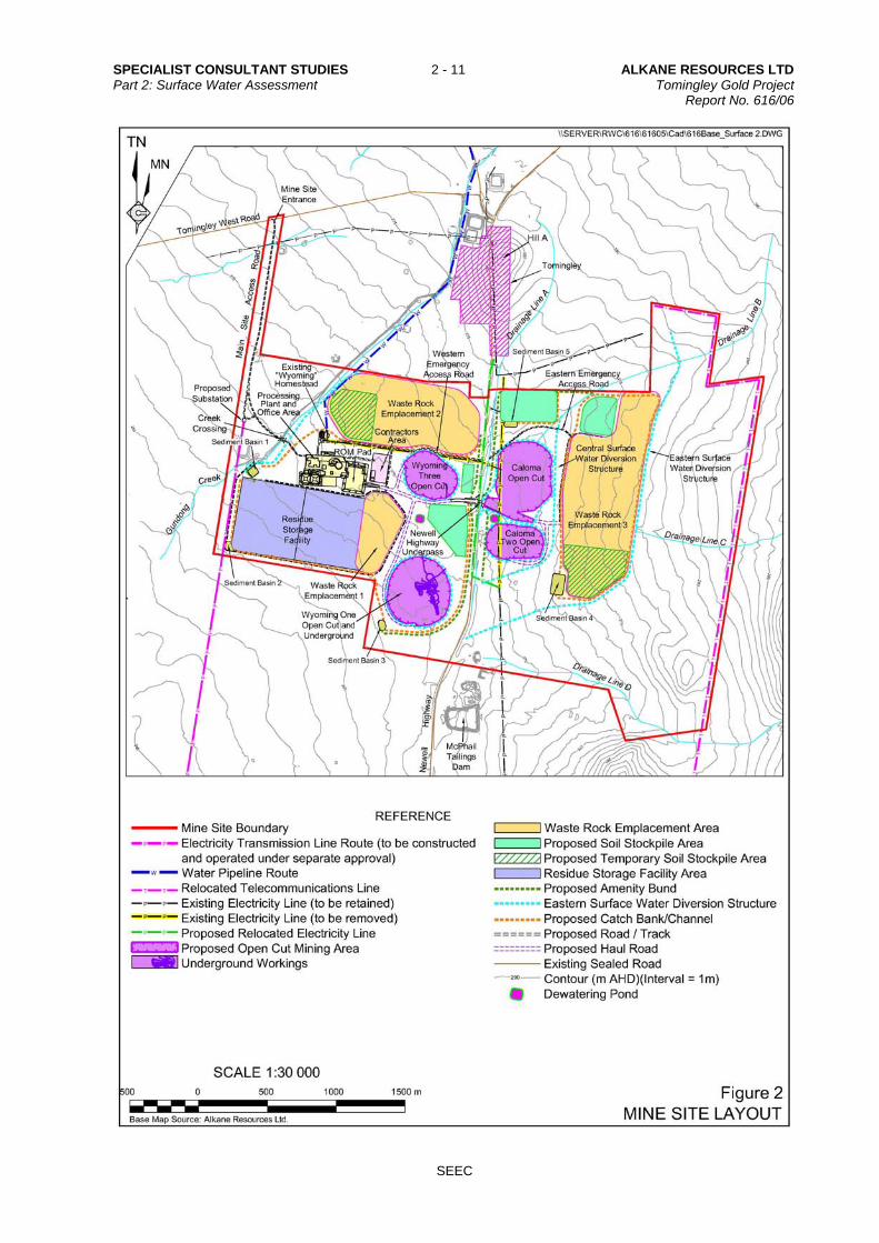
Figure 2 Mine Site Layout
A4/Colour

ALKANE RESOURCES LTD 2 - 12 SPECIALIST CONSULTANT STUDIES Tomingley Gold Project Part 2: Surface Water Assessment Report No. 616/06
SEEC
Figure 3 Tomingley – Narrabri Water Pipeline Route (0 to 22km)
A4/Colour

SPECIALIST CONSULTANT STUDIES 2 - 13 ALKANE RESOURCES LTD Part 2: Surface Water Assessment Tomingley Gold Project Report No. 616/06
SEEC
Figure 4 Tomingley – Narrabri Water Pipeline Route (22km to 46km)
A4/Colour
ALKANE RESOURCES LTD 2 - 14 SPECIALIST CONSULTANT STUDIES Tomingley Gold Project Part 2: Surface Water Assessment Report No. 616/06
SEEC
2.2 OVERVIEW OF THE PROJECT
The Project incorporates two separate component areas, each of which are illustrated on Figures 2, 3 and 4, and described as follows.
Establishment of infrastructure required for the Project, including a water supply pipeline, an underpass beneath the Newell Highway, and vegetated amenity bunds.
Extraction of waste rock and ore material from four open cut areas, namely:
Caloma Open Cut (approximately 19ha);
Caloma Two Open Cut (indicative design approximately 9ha);
Wyoming Three Open Cut (approximately 10ha); and
Wyoming One Open Cut (approximately 19ha).
Extraction of waste rock and ore material from the Wyoming One Underground.
Construction of three waste rock emplacements covering a combined area of approximately 129ha.
Construction and use of various haul roads, including an underpass under the Newell Highway, and a run-of-mine (ROM) pad.
Construction and use of a processing plant and office area, incorporating a crushing and grinding circuit, a standard carbon-in-leach (CIL) processing plant, site offices, workshops, ablutions facilities, stores, car parking, and associated infrastructure.
Construction and use of a residue storage facility (approximately 49ha).
Construction and use of a transformer and electrical distribution network within the Mine Site (from the 20km of 66kV electricity transmission line from Peak Hill to the Mine Site to be constructed under separate approval).
Construction and use of an approximately 46km water pipeline, from a licensed bore located approximately 7km to the east of Narromine, to the Mine Site.
Relocation of existing items of infrastructure, including a 22kV power line which currently passes over the area of the Caloma and Caloma Two Open Cuts.
Re-routing (node to node) of a 4.2km section of a Nextgen Network fibre optic cable (telecommunications line).
Construction and use of ancillary infrastructure, including the Main Site Access Road and intersection with Tomingley West Road.
Construction of soil stockpiles (for use in rehabilitation works).
Construction of the Eastern Surface Water Diversion Structure to divert surface water flows to the east of mining and waste rock emplacement activities. Additional surface water management structures would be constructed within the Project Site to control surface water flows within the Mine Site.
Construction and use of dewatering ponds to store water accumulating in and pumped from the open cuts.

SPECIALIST CONSULTANT STUDIES 2 - 15 ALKANE RESOURCES LTD Part 2: Surface Water Assessment Tomingley Gold Project Report No. 616/06
SEEC
Disturbance associated with the mining and associated activities would be progressively rehabilitated to create a geotechnically stable final landform, suitable for a final land use of nature conservation, agriculture, tourism and/or light industry. It is noted that the design of the proposed Caloma Two Open Cut is an indicative design only, with additional drilling required to further define the mineralisation. As a result, the indicative design for the Caloma Two Open Cut presented (Figure 2) represents the maximum area that would be developed. The development of this maximum impact footprint has been taken into account in all other aspects of the Project, including the required capacity, layout and design of the waste rock emplacements and residue storage facility, and the life of the Project. Approval is sought for the proposed design, acknowledging that the final design of the open cut would be the same size or smaller than that displayed. Full details of the Tomingley Gold Project are described in the Section 2 of the Environmental Assessment, prepared by R.W. Corkery & Co. Pty Limited.
3 STUDY AREA
For the purposes of this Surface Water Assessment, the “Study Area” is defined as the Mine Site (excluding the TNWP route) plus the entire upstream catchment that drains onto it. While the majority of this study focuses on the Mine Site, the external catchments are included within the Study Area where they generate runoff and stream flow that affect the Mine Site, or where they are subject to flooding in the vicinity of the Mine Site. However, outside of the Mine Site, only basic landscape observations were made to determine surface water and flow conditions. The location of the Mine Site in relation to the upstream catchments is shown in Figure 5. As noted above, the TNWP Route is not included in the scope of this report and is excluded from the overall Surface Water Management Study Area. We anticipate that neither the establishment nor operation of this aspect of the Project would significantly affect surface water. As such, consideration of surface water management over the TNWP Route is beyond the scope of this assessment. The Mine Site covers approximately 776ha and lies to the immediate south of Tomingley. It is divided into two sections by the Newell Highway to form an Eastern Section and a Western Section (Figure 2). The Eastern Section of the Mine Site covers approximately 458ha in total including the Caloma and Caloma Two Open Cuts and Waste Rock Emplacement (WRE) 3. The Western Section of the Mine Site covers approximately 318ha and would include Wyoming Open Cuts One and Three, Wyoming Three underground mine, WRE 1 and 2, the proposed processing area and residue storage facility (RSF).
4 ENVIRONMENTAL SETTING
4.1 TOPOGRAPHY
The Mine Site is located on very gently inclined terrain in the Bogan River catchment on the western side of the Herveys Range. Slopes range from 1:325 (V:H) up to 1:40 (V:H), with typical slopes of around 1:100 (V:H) to 1:200 (V:H) (Figure 6). Surface elevations range from 265m AHD on the southwestern boundary to 284m AHD on the eastern boundary. The majority of the Mine Site falls in a generally southwesterly direction.

ALKANE RESOURCES LTD 2 - 16 SPECIALIST CONSULTANT STUDIES Tomingley Gold Project Part 2: Surface Water Assessment Report No. 616/06
SEEC
Figure 5 Mine Site and Surrounding Catchments within the Study Area

SPECIALIST CONSULTANT STUDIES 2 - 17 ALKANE RESOURCES LTD Part 2: Surface Water Assessment Tomingley Gold Project Report No. 616/06
SEEC
Figure 6 Regional Setting, Topography and Drainage
ALKANE RESOURCES LTD 2 - 18 SPECIALIST CONSULTANT STUDIES Tomingley Gold Project Part 2: Surface Water Assessment Report No. 616/06
SEEC
The remainder of the Study Area outside the Mine Site consists of gently undulating low rises and hills with slopes typically between 1:50 (V:H) and 1:10 (V:H). Elevation increases east of the Mine Site to a maximum of approximately 373m AHD.
4.2 LAND USE
4.2.1 Mine Site
Most of the Mine Site is cleared and has been previously used for agriculture (grazing pasture or crop production). A number of unsealed access tracks traverse the existing paddocks. A single homestead, located within the Western Section of the Mine Site (Figure 2), would be retained as a site office building. Presently, access to both the eastern and western sections of the Mine Site is provided directly from the Newell Highway. While an access point to the Newell Highway would be retained as an emergency access, the main access to the Mine Site would be from Tomingley West Road. An underpass would be constructed under the Newell Highway to provide access between the Eastern And Western Sections of the Mine Site. The location of the new access point and Newell Highway underpass are identified on Figure 2 and the construction and operation of these features is discussed in detail in Section 2 of the Environmental Assessment.
4.2.2 Surrounding Lands
The lands surrounding the Mine Site to the east, south and west have been cleared, mainly for cropping, with steeper areas remaining under native timber. Surface rock outcropping is common in the upper reaches of the Study Area. The town of Tomingley lies to the north of the Mine Site. The abandoned Myall United Gold Mine at McPhail (“McPhails Mine”) is located to the immediate south of the Mine Site with some other minor workings located to the northwest.
4.3 SOILS
Soils within the Mine Site are described in detail in a separate Soils Assessment prepared by Sustainable Soils Management Pty Ltd (SSM, 2011), included as Part 8 of the Specialist Consultant Studies Compendium (hereon referred to as SSM (2011)). SSM (2011) identifies six soil types, five of which are well-drained. However, one soil type, namely the Sodic Gilgaied Dermosol east of the Newell Highway, is poorly-drained. Overall, SSM (2011) identified that 89% of the Mine Site was well-drained, with the remaining 11% poorly-drained. SSM (2011) identifies the soils as having a significant risk of dispersion, most likely necessitating flocculation to achieve adequate settling in sediment-control structures. Soil erodibility was identified as moderate to high (K-Factor of 0.04 to 0.05). Acid sulphate soils are not expected to be an issue at this site due to its elevation. Acid sulphate soils only occur on lands below 10m AHD.

SPECIALIST CONSULTANT STUDIES 2 - 19 ALKANE RESOURCES LTD Part 2: Surface Water Assessment Tomingley Gold Project Report No. 616/06
SEEC
4.4 DRAINAGE
4.4.1 Regional Drainage
The Mine Site is located within the catchment of the Bogan River (Figure 6). Poorly defined ephemeral drainages on the western side of the Herveys Range flow to the Bogan River located approximately 11km to the southwest of the Mine Site. The Bogan River flows in a generally northwesterly direction before merging with the Darling River approximately 80km upstream of Brewarrina.
4.4.2 Local Water Courses and Dams
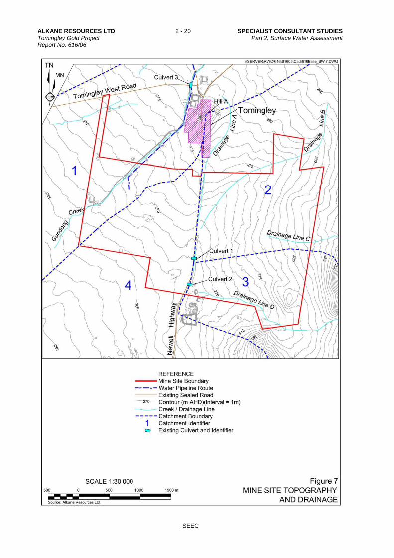
Gundong Creek traverses the northwestern section of the Mine Site, while a number of unnamed, poorly-defined drainage lines occur within and immediately north and east of the Mine Site (Figure 7). These have been labelled Drainage Lines A, B, C and D respectively for ease of reference. The natural westerly and southwesterly flows in Drainage Lines A, B, C and D are disrupted by the presence of the Newell Highway, with flows collecting on the eastern side of the Highway then crossing at a series of culverts near the southern boundary of the Mine Site. This combined drainage flows as overland flow (i.e. no defined channel) westward from this point, eventually joining Gundong Creek approximately 5km downstream from the Mine Site. Numerous small dams exist on the Mine Site. While many of these would be removed to make way for the proposed mining operations, one farm dam on the western boundary of the Mine Site would be retained as a sediment retention structure (Sediment Basin 1 on Figure 2). Gundong Creek has its headwaters in the Herveys Range approximately 12km to the east of the Mine Site. A heritage assessment for the area conducted by OzArk Environment and Heritage Management Pty Ltd (OzArk 2011) identifies that Gundong Creek formally dissipated at a place called ‘Ten Ponds’ (also possibly known as “Ten Mile Holes”) to the northeast of Tomingley and that the current creek was formed by cutting a channel for growing vegetables and mineral processing during the 1800’s. Figures 5 and 7 show the four main catchments that would be affected by the Mine Site. These are hereon referred to as Catchment 1, Catchment 2, Catchment 3 and Catchment 4 and are described in Section 4.4.3.
ALKANE RESOURCES LTD 2 - 20 SPECIALIST CONSULTANT STUDIES Tomingley Gold Project Part 2: Surface Water Assessment Report No. 616/06
SEEC
Figure 7 Mine Site Topography and Drainage

SPECIALIST CONSULTANT STUDIES 2 - 21 ALKANE RESOURCES LTD Part 2: Surface Water Assessment Tomingley Gold Project Report No. 616/06
SEEC
4.4.3 Catchment Areas and Boundaries
4.4.3.1 Gundong Creek – Catchment 1
Gundong Creek drains an area of approximately 10 600ha upstream of where it enters the Mine Site, although it is unlikely that the currently formed creek conveys all flows from that entire catchment. It is likely that a significant proportion of the peak flows are diverted away from the creek well before they reach the proposed Mine Site, as indicated by the following site observations.
At the bridge across Gundong Creek on the Newell Highway, located approximately 3km northeast of Tomingley, is a topographical feature shown on the Department of Lands mapping called the “Gundong Overflow”. This is adjacent to the previously discussed “Ten Mile Holes”. There are several culverts located immediately to the north of the bridge that suggests that major flows are diverted away from the Gundong Creek catchment.
The capacity of the creek downstream of the bridge would be insufficient to convey the full peak flows from the entire catchment. It is likely that major flows would overtop the creek and sheet flow in a southwesterly direction away from the creek.
The crossing at Tomingley West Road is insufficient to pass a 100-year ARI peak flow. Surplus run-off would overtop the crest on the western side of Tomingley West Road and flow in a southwesterly direction away from the creek.
The extent of the catchment area is shown in Figure 5. Approximately 15% (110ha) of the Mine Site drains directly to Gundong Creek under the present conditions as it passes through the Mine Site. Figure 5 also shows the full extent of the Gundong Creek catchment to a point downstream of the Mine Site where Catchment 4 adjoins Catchment 1.
4.4.3.2 Drainage Lines A, B, C – Catchment 2
Drainage Lines A, B and C drain lands upstream of where they enter the Eastern Section of the Mine Site and, under the present conditions, flow through the Mine Site. These are collectively assessed as Catchment 2, as shown on Figure 5. Catchment 2 is intercepted by the Newell Highway and combined at a single culvert, where it outlets into Catchment 4 (see Figure 7 and Section 4.4.2).
4.4.3.3 Drainage Line D – Catchment 3
The catchment area of Drainage Line D is assessed as Catchment 3 on Figure 6. Only minor disturbance is proposed within the area of Catchment 3 as a result of the Project. Catchment 3 outlets via two culverts under the Newell Highway and joins into Catchment 4 (see Figure 7 and Section 4.4.2).

ALKANE RESOURCES LTD 2 - 22 SPECIALIST CONSULTANT STUDIES Tomingley Gold Project Part 2: Surface Water Assessment Report No. 616/06
SEEC
4.4.3.4 Catchment 4
Catchment 4 includes part of the Mine Site on the western side of the Newell Highway, plus all outflows from Catchments 2 and 3 (as show on Figure 5). Drainage in Catchment 4 is poorly-defined, with no definite channel and all flows are reported (anecdotally) to occur as overland or sheet flow. This catchment is assessed both in isolation (i.e. excluding the inflows from Catchments 2 and 3) and including the inflows from Catchments 2 and 3. This is to determine what impacts might occur within Catchment 4 if flows from Catchments 2 and/or 3 were diverted either north of the Mine Site (i.e. directly to Gundong Creek) or into neighbouring catchments to the south.
4.5 FLOODING
Gundong Creek is part of a significant catchment upslope of the Mine Site, although it’s unlikely that flows from the entire catchment are conveyed via Gundong Creek for the reasons already discussed in Section 4.4.3.1. Even though this is the case, significant rainfall events in the upstream catchment can generate over-bank flows in Gundong Creek in the vicinity of the Mine Site, particularly in the western section of the Mine Site. Existing levies around the main centre of the Tomingley township are evidence of potential flooding in this area. We are advised by Michael Sutherland from Alkane Resources that the Tomingley West Road is subject to periodic inundation in the vicinity of the Main Site Access Road (see Figure 2). Additionally, flooding has historically occurred at the culvert crossings of the Newell Highway (see Figure 7) when flows in Drainage Lines A, B, C and D exceed the culverts’ capacities. Surface flow and flood modelling for Gundong Creek and the four minor drainage lines is included in Section 5 to assess the influence of the Project on surface flows and flooding behaviour.
4.6 GROUNDWATER
Groundwater within and adjacent to the Mine Site is described in two documents, namely:
the groundwater assessment prepared by The Impax Group (incorporating groundwater modelling completed by Australasian Groundwater and Environmental Consultants Pty Ltd) and presented as Part 3 of the Specialist Consultant Studies Compendium (Impax, 2011); and
a Groundwater Investigation Report prepared by Coffey Geotechnics Pty Ltd 10 August 2007 (Coffey, 2007) and additional report dated 8 April 2008 (Coffey, 2008).
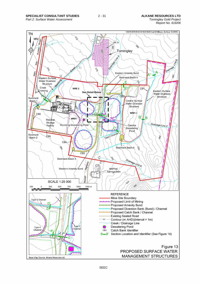
Impax (2011) identified the potential for the open cuts to intercept fractured groundwater-bearing layers, with subsequent inflows into the open cut void. However, hydraulic conductivity within the surrounding layers is low (combined inflows from the three open cuts of 1.06L/s, Impax (2011)) such that pit inflows from groundwater are expected to be minimal. Any pit inflows of groundwater would be pumped to one of two dewatering ponds (identified as the Wyoming Dewatering Pond and Caloma Dewatering Pond on Figure 13) and used for processing and dust suppression. There would be nil discharge of water pumped out of the pits due to the risk of it being saline.

SPECIALIST CONSULTANT STUDIES 2 - 23 ALKANE RESOURCES LTD Part 2: Surface Water Assessment Tomingley Gold Project Report No. 616/06
SEEC
Coffey (2008) includes monitoring in four boreholes in and around the Mine Site. Water levels in two boreholes located in the northeastern and southeastern corners of the western section of the Mine Site near the Newell Highway remained seasonally stable. Two other boreholes near the abandoned McPhails Mine workings rose significantly. This is believed to be in response to a significant rainfall event of approximately 150mm on 27 December 2007 that infiltrated the old workings which remain partially open at the surface. SSM (2009) includes results of an electromagnetic survey which suggests the presence of potential springs in the northwestern corner of the Mine Site. However, Impax (2010) found the potential for existing groundwater outflows on the Mine Site was low.
4.7 VEGETATION
The majority of the Mine Site is currently used for intensive crop farming including annual cereal crops and some native pasture. Although the majority of the Mine Site has been cleared, stands of remnant woodland exist along drainage lines and some portion boundaries.
4.8 CLIMATE
4.8.1 Rainfall
Three nearby rainfall stations were investigated as part of this assessment. Of these, only the Peak Hill Post Office station is operated by the Bureau of Meteorology. The rainfall stations are as follows.
Peak Hill Post Office – Station Number 050031 located approximately 16km to the south of the Mine Site. This station has 119 years of rainfall records from 1890 to the present. This station is operated by the Bureau of Meteorology and the rainfall record is 99% complete.
Wyanga (Barcoo) – Station Number 051008 located approximately 14km to the northwest of the Mine Site. This station has rainfall records from 1899 to the present. This station is not operated by the Bureau of Meteorology so the completeness of the rainfall record is not known. An investigation showed significant gaps in the data record.
Tomingley (Gundongs) – Station Number 050139 located approximately 10.8km to the northeast of the Mine Site. This station has rainfall records from 1965 to the present. This station is not operated by the Bureau of Meteorology so the completeness of the rainfall record is not known. An investigation showed significant gaps in the data record.
Annual average rainfall at each of the above rainfall stations is recorded as follows.
Peak Hill Post Office – 559mm/year.
Wyanga (Barcoo) – 499mm/year.
Tomingley (Gundongs) – 557mm/year.

ALKANE RESOURCES LTD 2 - 24 SPECIALIST CONSULTANT STUDIES Tomingley Gold Project Part 2: Surface Water Assessment Report No. 616/06
SEEC
Although the Tomingley (Gundongs) and Wyanga (Barcoo) stations are closer to the Mine Site, data from the Peak Hill Post Office rainfall station were selected as being the most reliable due to the length and completeness of the rainfall record, and the fact this station is operated by the Bureau of Meteorology. Furthermore, the long-term rainfall average at Peak Hill is not significantly different to that at the Tomingley (Gundongs) station and, as such, it can be considered representative of the typical climate conditions expected at the Mine Site. An analysis of the monthly rainfall pattern for Peak Hill Post Office is included in Figure 8. Figure 8 shows that rainfall is fairly consistent throughout the year, with a slight summer dominance and a minor peak in January. The record from 1890 to the present includes both wet and dry periods, so can be considered a good representation of the long-term average for this site (559mm/yr).
Peak Hill Post Office - 1890 to Present
0
10
20
30
40
50
60
70
Janu
ary
Febr
uary
Mar
chApril
May
June Ju
ly
Augus
t
Septe
mbe
r
Octob
er
Novem
ber
Decem
ber
Rai
nfa
ll (
mm
)
Figure 8 Monthly rainfall analysis for Peak Hill Post Office Station 050031
4.8.2 Evaporation
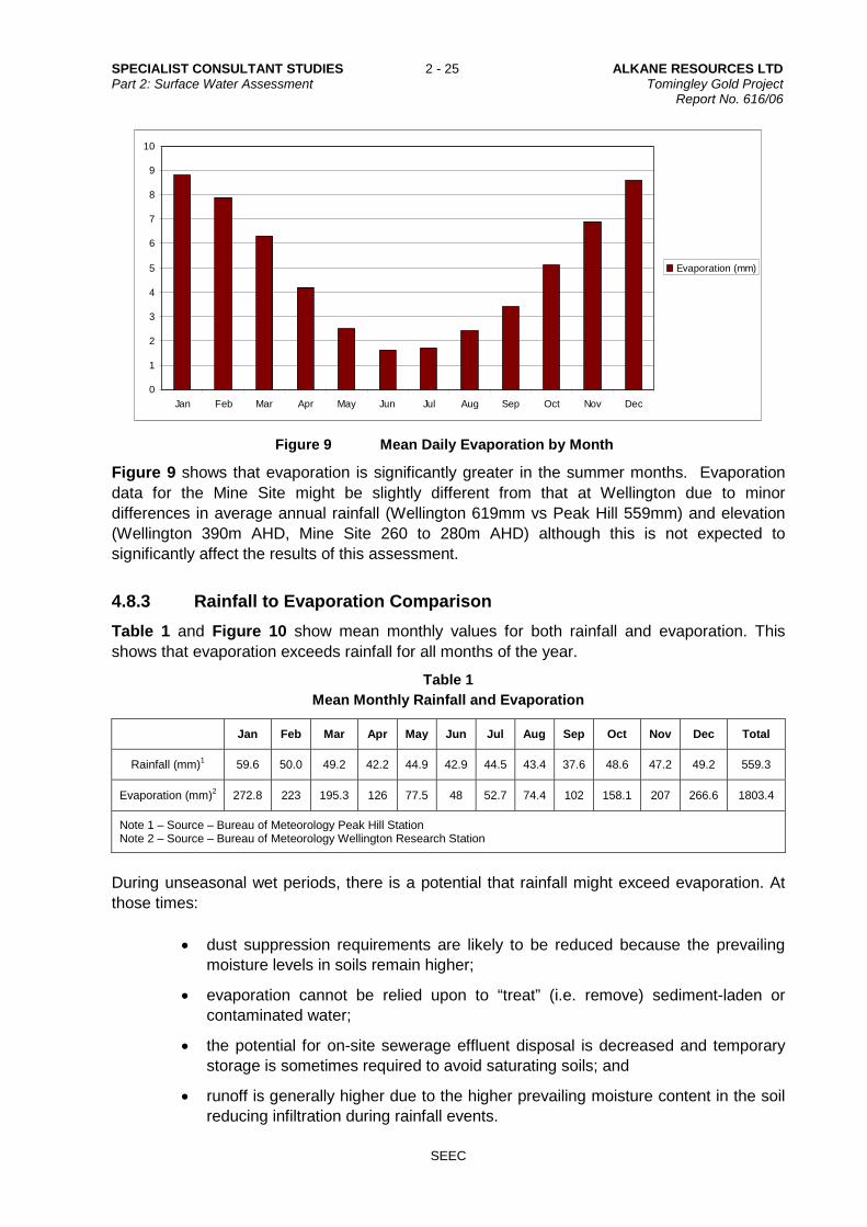
The closest Bureau of Meteorology meteorological station collecting evaporation data is at the Wellington Research Centre, approximately 68km to the east. The station commenced in 1946 and was closed 24 February 2005. Figure 9 shows an analysis of the average daily evaporation occurring in each month up to 2005.
SPECIALIST CONSULTANT STUDIES 2 - 25 ALKANE RESOURCES LTD Part 2: Surface Water Assessment Tomingley Gold Project Report No. 616/06
SEEC
0
1
2
3
4
5
6
7
8
9
10
Jan Feb Mar Apr May Jun Jul Aug Sep Oct Nov Dec
Evaporation (mm)
Figure 9 Mean Daily Evaporation by Month
Figure 9 shows that evaporation is significantly greater in the summer months. Evaporation data for the Mine Site might be slightly different from that at Wellington due to minor differences in average annual rainfall (Wellington 619mm vs Peak Hill 559mm) and elevation (Wellington 390m AHD, Mine Site 260 to 280m AHD) although this is not expected to significantly affect the results of this assessment.
4.8.3 Rainfall to Evaporation Comparison
Table 1 and Figure 10 show mean monthly values for both rainfall and evaporation. This shows that evaporation exceeds rainfall for all months of the year.
Table 1
Mean Monthly Rainfall and Evaporation
Jan Feb Mar Apr May Jun Jul Aug Sep Oct Nov Dec Total
Rainfall (mm)1 59.6 50.0 49.2 42.2 44.9 42.9 44.5 43.4 37.6 48.6 47.2 49.2 559.3
Evaporation (mm)2 272.8 223 195.3 126 77.5 48 52.7 74.4 102 158.1 207 266.6 1803.4
Note 1 – Source – Bureau of Meteorology Peak Hill Station Note 2 – Source – Bureau of Meteorology Wellington Research Station
During unseasonal wet periods, there is a potential that rainfall might exceed evaporation. At those times:
dust suppression requirements are likely to be reduced because the prevailing moisture levels in soils remain higher;
evaporation cannot be relied upon to “treat” (i.e. remove) sediment-laden or contaminated water;
the potential for on-site sewerage effluent disposal is decreased and temporary storage is sometimes required to avoid saturating soils; and
runoff is generally higher due to the higher prevailing moisture content in the soil reducing infiltration during rainfall events.

ALKANE RESOURCES LTD 2 - 26 SPECIALIST CONSULTANT STUDIES Tomingley Gold Project Part 2: Surface Water Assessment Report No. 616/06
SEEC
0
50
100
150
200
250
300
Jan Feb Mar Apr May Jun Jul Aug Sep Oct Nov Dec
0
50
100
150
200
250
300
Rainfall (mm)
Evaporation (mm)
Figure 10 Mean Monthly Rainfall vs Mean Monthly Evaporation
5 SURFACE WATER ASSESSMENT
5.1 PEAK FLOWS
5.1.1 Background and Modelling Procedure
Estimations for the peak runoff from the Study Area were determined using the Rational Method for Catchments 2, 3 and 4 (Figure 5) in accordance with Engineers Australia (2002) Australian Rainfall and Runoff Volume 1. Peak flows in Gundong Creek, represented by Catchment 1 on Figure 5 were modelled using XP-RAFTS. A copy of the catchment model generated in XP-RAFTS is shown in Figure 11. Figure 12 shows a detail of this XP-RAFTS modelling around the Mine Site itself. Spreadsheets generated by the model are included in Appendix 3.
Figure 11 XP-RAFTS Model of Gundong Creek (Catchment 1)

SPECIALIST CONSULTANT STUDIES 2 - 27 ALKANE RESOURCES LTD Part 2: Surface Water Assessment Tomingley Gold Project Report No. 616/06
SEEC
Figure 12 Detail of XP-RAFTS Model Across the Actual Mine Site
The Intensity Frequency Duration (IFD) rainfall data for the site has been calculated from Australian Rainfall and Runoff (Institution of Engineers, 1998). A copy of the IFD chart for the site is attached in Appendix 1. Table 2 summarises the various inputs for peak flow modelling. Note that Table 2 includes each of Catchments 1, 2, 3 and 4, plus input values for each of these catchments with the Mine Site area excluded. Catchment 4 was initially modelled separately to assess how the Mine Site would affect peak flows if water from Catchments 2 and 3 was diverted away from it. An assessment is also included showing how the combined flows in Catchments 2, 3 and 4 might be affected by the Project. Note that, although Catchment 1 has an upstream area of some 10 600ha, floodwaters would exceed the capacity of Gundong Creek and flow in a southwesterly direction over a wide floodplain upstream of the Mine Site (as previously discussed in Section 4.4.3.1). As a result, it is difficult to quantify the exact catchment area contributing to flooding at the Mine Site from Catchment 1. A conservative estimate based on the location of existing culverts under Tomingley Narromine Road suggest that at least 1400ha of catchment is directed well north of the Mine Site by the existing road culverts and natural overland flow. We estimate that run-off from at least half of Catchment 1 would bypass the Mine Site when taking into account loss of flows at the “Gundong Overflow” previously discussed in Section 4.4.3.1. When calculating peak flows (Tables 2 and 3) and flood heights (Table 4), we have used the figure of 9 200ha for Catchment 1.

ALKANE RESOURCES LTD 2 - 28 SPECIALIST CONSULTANT STUDIES Tomingley Gold Project Part 2: Surface Water Assessment Report No. 616/06
SEEC
Table 2
Input Data for Peak Flow Calculations
Catchment Area (km2)
tc (hours)
Rainfall Intensity (I) mm/hr C10 mod factor
(100/A)0.15
Derived C10 1yr, tc
5yr, tc
10yr, tc 20yr,
tc 50yr, tc
100yr, tc
1 92 4.243 7.15 12.0 13.7 16.0 19.1 21.5 1.01 0.10
2 18 2.279 11.1 18.8 21.5 25.2 30.2 34.1 1.29 0.13
3 13.5 2.043 12.0 20.3 23.3 27.2 32.7 37.0 1.35 0.14
4 18.04 2.281 11.1 18.7 21.4 25.0 30.0 34.0 1.29 0.13
2+3+4 49.54 3.349 8.46 14.2 16.3 19.0 22.7 25.7 1.11 0.11
1 (ex Mine Site)
91.8 4.231 7.16 12.0 13.7 16.0 19.1 21.6 1.01 0.10
2 (ex Mine Site)
16.56 2.208 11.4 19.2 22.0 25.7 30.9 34.9 1.31 0.13
3 (ex Mine Site)
13.43 2.039 12.0 20.3 23.3 27.3 32.7 37.1 1.35 0.14
4 (ex Mine Site)
16.05 2.182 11.5 19.4 22.2 26.0 31.1 35.3 1.32 0.13
2+3+4 (ex Mine Site)
46.04 3.257 8.63 14.5 16.6 19.4 23.2 26.2 1.12 0.11
Table 2 notes: Catchment refers to the catchment number in Figure 5 tc is Time of Concentration (in hours) C10 is the runoff coefficient (dimensionless) in the 10-year storm event. These have been derived for the
Study Area as per the procedure in Engineers Australia (2002). Note that “ex Mine Site” only refers to that part of the Mine Site that would be excluded from each
catchment as a result of bunding, not the full extent of the actual Mine Site within each catchment.
The Mine Site is dominated by well-drained, moderately permeable, silty loam soils. The initial and continuing infiltration rates in XP-RAFTS were assumed from broad data provided in SSM (2009) as follows.
Initial loss: 25mm
Continuing infiltration rate: 2.5mm/hr.
Detailed soils information is not available for the remainder of the Study Area outside the Mine Site. Hence, the same infiltration rates were adopted within that area in the absence of any more specific information.
5.1.2 Peak Flow Run-off Results
Peak flow calculations for each of the catchments are detailed in Table 3, along with calculations for each catchment excluding the area of the Mine Site contained therein. As noted in Section 4.4.2, flows from Catchments 2 and 3 converge at a series of existing box culverts under the Newell Highway towards the southern end of the Mine Site. They then enter Catchment 4. Catchment 4 was initially modelled separately to assess how the Mine Site would affect peak flows if water from Catchments 2 and 3 was diverted away from it. An assessment is also included showing how the combined flows in Catchments 2, 3 and 4 might be affected by the Project.

SPECIALIST CONSULTANT STUDIES 2 - 29 ALKANE RESOURCES LTD Part 2: Surface Water Assessment Tomingley Gold Project Report No. 616/06
SEEC
Table 3
Peak Flow Calculations for Each Catchment
ARI1 (years)
Frequency Factor
1 2 3 4 2+3+4 1 (ex Mine Site)
2 (ex Mine Site)
3 (ex Mine Site)
4 (ex Mine Site)
2+3+4 (ex Mine
Site)
(m3/s) (m3/s) (m3/s) (m3/s) (m3/s) (m3/s) (m3/s) (m3/s) (m3/s) (m3/s)
1 yr,tc 0.38 0.037 2.730 2.311 2.768 4.919 0.032 2.612 2.301 2.566 4.715
5 yr,tc 0.78 31.300 9.490 8.025 9.573 16.949 31.160 9.029 7.989 8.884 16.262
10 yr,tc 1 46.500 13.914 11.808 14.046 24.943 46.300 13.264 11.756 13.033 23.868
20 yr,tc 1.26 69.400 20.549 17.369 20.675 36.634 69.100 19.523 17.356 19.233 35.147
50 yr,tc 1.71 109.100 33.422 28.338 33.670 59.399 108.700 31.857 28.213 31.222 57.042
100 yr,tc 2.14 117.900 47.227 40.128 47.755 84.160 117.300 45.028 40.059 44.349 80.617
Note 1: tc= Time of Concentration
A preliminary design check of the capacity of the existing culverts conveying flows from Catchments 2 and 3 suggests they are only capable of safely passing flows in the 1-year storm event. A copy of the design check is included in Appendix 2. Significant upgrading of the culverts would be required to ensure safe flows for all storm events up to the 100-year ARI event. However, as noted in Table 3, the Project would actually decrease peak flow volumes in all storm events, albeit by a relatively minor amount. As the Project is unlikely to impact on the ability of the existing culverts to convey flows in the relative design storm events, upgrading of these culverts, if required, should not be the responsibility of the Proponent.
5.2 FLOOD MODELLING
5.2.1 Introduction
An assessment was made of the pre-development and operational-stage flood heights at the Mine Site for Catchment 1 (i.e. Gundong Creek) and within Catchment 2 (Drainage Lines A, B and C). The purpose of this was to determine:
the height of any bunding that might be required to protect the Mine Site from floodwaters from Gundong Creek;
whether bunding would be required around the Caloma Open Cut to protect it from floodwaters backing up due to the constriction of flows in the Newell Highway culverts; and
the change in flood elevation that might occur within Catchment 1 as a result of the main site access road and Gundong Creek crossing, plus bunding the Mine Site (thereby excluding it from the land area available for floodwaters to spread over).
Note that a flood assessment was not conducted for Catchment 3 because it would be mostly unaffected by the Project and any flooding in Catchment 3 is unlikely to affect structures within the Mine Site. An assessment was not conducted for Catchment 4 because the existing culverts under the Newell Highway effectively act to restrict flows, minimising the risk of downstream flooding. Flood waters from Catchments 2 (and 3) are likely to temporarily back up as a result of the culvert constriction, and this is assessed in Section 5.2.3.

ALKANE RESOURCES LTD 2 - 30 SPECIALIST CONSULTANT STUDIES Tomingley Gold Project Part 2: Surface Water Assessment Report No. 616/06
SEEC
5.2.2 Catchment 1 Flood Heights
A HEC-RAS flood model was developed along the centreline of Gundong Creek which passes through the western side of the Mine Site (see Figure 2). This was used to determine the various peak flood heights up to and including the 100-year ARI flood within Catchment 1. Flood heights were determined under the existing conditions (pre-development) and under the proposed conditions (post-development) and included the Main Site Access Road, culvert crossing over Gundong Creek and surface water management structures proposed to divert, capture and direct the flow of water on and around the Mine Site (see Figures 13 and 14). The post-development model also includes the earth bund effectively excluding the Mine Site from Catchment 1. The full 100-year ARI peak flow for the entire Catchment 1 has been used as a conservative figure to determine the minimum bund height even though the majority of the flows above the capacity of Gundong Creek would bypass the Mine Site to the northwest as previously discussed in Section 4.4.3.1. We estimate that Gundong Creek would most likely only convey up to the 2-year ARI peak flow from Catchment 1 because excess flows above the 2-year ARI would flow overland to the northwest as previously discussed. The results of the flood modelling using the 100-year peak flow are included in Table 4. A plan showing the river stations or cross-sections relating to Table 4 is included in Appendix 7. This plan also shows the spatial extent of the more realistic 2-year ARI peak storm at the location of the proposed main access crossing over Gundong Creek to the Mine Site. HEC-RAS outputs are also included in Appendix 7. An analysis and impact assessment based on these results is included in Section 6 of this report.
Table 4
Modelled 100-year Flood Heights in Catchment 1
River Station
Ground Level (m
AHD)
100-year flood levelunder existing
conditions (m AHD)
100-year flood level after development of
Mine Site (m AHD)
Change in 100-year flood level
0 264.00 263.86 263.75 -0.11m 500 265.75 265.77 265.75 -0.02m 1000 267 267.63 267.72 +0.09m 1280 268.10 268.47 268.85 +0.38m 1500 268.90 269.23 269.25 +0.02m 2000 270.80 270.99 271.02 +0.03m 2500 272.70 273.14 273.13 -0.01m
The 100-year ARI flood heights for Catchment 1 (Gundong Creek) shown in Table 4 suggest that bunds would be required to exclude the Mine Site from floodwaters. A minimum flood height of 0.75m plus at least 0.5m of freeboard would be required for the 100-year ARI flood. The freeboard should be included to allow for the Probable Maximum Flood and to accommodate unforseen restrictions on flows that might occur off-site and downstream of the points modelled and to allow for earth bund stability when inundated.
SPECIALIST CONSULTANT STUDIES 2 - 31 ALKANE RESOURCES LTD Part 2: Surface Water Assessment Tomingley Gold Project Report No. 616/06
SEEC
Figure 13 Proposed Water Control Structures on the Mine Site

ALKANE RESOURCES LTD 2 - 32 SPECIALIST CONSULTANT STUDIES Tomingley Gold Project Part 2: Surface Water Assessment Report No. 616/06
SEEC
Figure 14 Indicative Bund and Surface Water Control Structure Design

SPECIALIST CONSULTANT STUDIES 2 - 33 ALKANE RESOURCES LTD Part 2: Surface Water Assessment Tomingley Gold Project Report No. 616/06
SEEC
5.2.3 Catchment 2 Flood Heights
As previously identified, the existing culverts under the Newell Highway at the outlet of Catchment 2 are not sufficient to convey the 100-year ARI flood event. In such an event, water would most likely flow over the Newell Highway or could back up onto the Mine Site east of the Newell Highway. Anecdotal evidence provided by Kim Strahorn from nearby property “Ellerslie” suggests that very large rain events in the past have led to water backing up and over the Newell Highway at this location, but only for a short time. Modelling was conducted using DRAINS for Catchment 2 to determine the total volume of water that might occupy the Mine Site east of the Newell Highway in the 100-year ARI event (i.e. assuming 100% blockage of the existing culverts under the highway). This is estimated at approximately 46 000m3 of water. An assessment of the available volume within the Eastern and Central Surface Water Diversion Structures (Figure 13), which would convey flows in Drainage Lines A, B and C through or around the eastern portion of the Mine Site suggests that this 46 000m3 of water could be comfortably accommodated within the channels without overtopping into the Mine Site or onto neighbouring lands. Details of these structures are in a separate report by Mintrex and are summarised in the Environmental Assessment.
5.3 SURFACE WATER QUALITY AND VOLUMES
5.3.1 Background and Introduction
Surface water quality was assessed for both the existing conditions (i.e. pre-development) and proposed conditions during operation using MUSIC (Model for Urban Stormwater Improvement Conceptualisation). MUSIC contains algorithms based on the known performance characteristics of common stormwater quality improvement structures used in Australia. These data are derived from research undertaken by the CRC for Catchment Hydrology (now part of eWater) and others. The models are appropriately calibrated and all amendments to MUSIC defaults are noted below. The modelling quantifies:
the levels of the principal pollutants before and after the development; and
changes in export levels because the development is there. Statistics are produced for flows (ML/yr) plus the load (kg/yr) and concentration (mg/L) of a range of common pollutants in stormwater including:
total suspended solids (TSS);
total phosphorus (TP);
total nitrogen (TN); and
gross pollutants (GP).
5.3.2 Modelling Area
For the purposes of MUSIC modelling, only the Mine Site itself is considered. The remainder of the Study Area is excluded from this modelling because surface conditions outside the Mine Site would not be modified by the Project.

ALKANE RESOURCES LTD 2 - 34 SPECIALIST CONSULTANT STUDIES Tomingley Gold Project Part 2: Surface Water Assessment Report No. 616/06
SEEC
In addition, the area to be occupied by the three open cuts and the RSF are excluded from both the pre-development and operational-stage models. This is because these areas would be either internally-draining or completely bunded and so excluded from generating runoff. To maintain consistency in the total surface area modelled in the pre-development and operational-stage models, the land area occupied by these features is excluded from both. While the spatial extent of soil stripping, waste-rock emplacement and mining operations would vary over the life of the mine, we have assumed the full extent of disturbance at a single time. This conservative approach addresses the potential for spatial or temporal changes in the way mine operations are carried out post approval (should project approval be granted).
5.3.3 Climate Data for MUSIC Modelling
Creation of a MUSIC catchment file requires an associated meteorological data file. Reliable pluviograph data for Wagga Wagga was used because it has a similar average annual rainfall pattern and amount to the site (Wagga Wagga AMO long-term average 564mm/yr, Peak Hill long-term average 559mm/yr). A 10-year period from 01/01/1980 to 31/12/1989 with a one-hourly interval was used because it includes both wetter-than average and dryer-than average years but, overall, is almost identical to the long-term site average. Statistics for rainfall and potential evapotranspiration (PET) are included in Table 5 and Figure 15.
Table 5
One-hourly Rainfall and PET statistics used in MUSIC models
Measure
Statistics
Mean Median Maximum Minimum 10%ile 90%ile Mean
annual (mm/yr)
Rainfall (mm/hr)
0.065 0.000 34.13 0.000 0.000 0.008 568
PET (mm/day)
3.316 2.670 5.810 1.170 1.290 5.170 1211
5.3.4 Pre-Development Modelling Calibration and Setup
Under existing conditions, impervious surfaces such as roofs, sealed roads, and other hardstand surfaces occupy only minimal areas within the existing area to be occupied by the Mine Site. The remainder of the Mine Site is used for agricultural purposes. As such, the existing conditions are modelled using a default “agricultural” node in MUSIC, set to 99% pervious area. Pervious area runoff and infiltration properties were determined from Macleod (2008) assuming 0.5m of sandy clay loam (note that soil depth in MUSIC only takes into account those layers directly affected by PET, although actual soils might be significantly deeper). Table 6 provides details of source node pervious area calibration. Although the report by SSM (2009) identifies several different soil types, upper soil layers were relatively consistent and can be reliably represented in a MUSIC model using a single suite of parameters for each source node across the Mine Site.

SPECIALIST CONSULTANT STUDIES 2 - 35 ALKANE RESOURCES LTD Part 2: Surface Water Assessment Tomingley Gold Project Report No. 616/06
SEEC
Figure 15 Time-series Chart for One-Hourly Rainfall and PET as Used in MUSIC Models
Table 6
Calibration of Pervious Area Properties for MUSIC Source Nodes (from Macleod, 2008)
MUSIC Parameter Calibration for source nodes at the Mine SiteSoil storage capacity 108mm Initial storage 30% Field capacity 83mm Infiltration capacity coefficient 200 Infiltration capacity exponent 2.5 Groundwater initial depth 30mm Daily recharge rate 35% Daily base flow rate 25% Daily deep seepage rate 5%
5.3.5 Operational-Stage Modelling Calibration and Setup
As discussed in Section 5.3.2, the area occupied by the three open cuts and the RSF are excluded from both the pre-development and operational-stage models. Table 7 details the base flow and storm flow properties used to calibrate various parts of the Mine Site in the operational stage. These are based on details for various land use and surface types described in SCA (2009). Pervious area properties for all nodes are set in accordance with Table 6. The overall area and impervious surface percentages for each source node are determined based on the proposed extent of various structures as illustrated on Figures 2 and 13 and described in Section 2 of the EA. In all cases, conservative (over) estimates were assumed.
1980 to 1989 inclusive
Rainfall Evapo-transpiration
08/12/198909/12/198709/12/198510/12/198310/12/1981
Milli
met
res
30
25
20
15
10
5
0

ALKANE RESOURCES LTD 2 - 36 SPECIALIST CONSULTANT STUDIES Tomingley Gold Project Part 2: Surface Water Assessment Report No. 616/06
SEEC
Table 7
MUSIC Stormwater Pollutant Input Parameters for Operational Areas of the Mine Site
Surface type Land use type* Flow type TSS (mg/L –log10) TP (mg/L –log10) TN (mg/L –log10) mean Std. dev mean Std. dev mean Std. dev
Operation facilities
Industrial land use Base flow 1.20 0.17 -0.85 0.19 0.11 0.12 Storm flow 2.15 0.32 -0.60 0.25 0.30 0.19
Stripping areas and WRE
Unsealed roads Base flow 1.20 0.17 -0.85 0.19 0.11 0.12 Storm flow 3.00 0.32 -0.30 0.25 0.34 0.19
Unused areas of Mine Site
Revegetated land Base flow 1.15 0.17 -1.22 0.19 -0.05 0.12 Storm flow 1.95 0.32 -0.66 0.25 0.30 0.19
(Note: * based on SCA, 2009). The operational-stage MUSIC modelling assumes the following.
Unsealed roads within the Mine Site would be provided with effective dust suppression to minimise the risk of erosion by wind or water.
The entire disturbed area on the Mine Site would be effectively bunded to exclude floodwaters and any run-on.
Drainage Lines A, B and C would be diverted around or through the Mine Site.
Sediment basins would be installed as described in Section 7.3.1.
The water management strategy described in Section 7 would be effectively implemented.
Internal roadways within the Mine Site would be significantly compacted.
Processing areas, plant and storage areas, plus other disturbed areas occupy 40ha with 70% effectively impervious (this is a conservative overestimate).
The internal road system is estimated at 20ha with 75% effective impervious area (assuming approximately 6.5km of roadway, 30m wide).
Soil stripping and waste rock emplacements are assumed to occupy 108ha, of which 30% is effectively impervious at any one time.
Sediment Basins 1, 2, 3 and 4 (see Figure 13) are modelled using a default “Sediment Basin” node in MUSIC, sized according to Section 7.3.1 and Appendix 5, and assuming an average depth of 2m. The Wyoming and Caloma Dewatering Ponds are excluded from the model because they are both for dewatering of the open cuts and would be operated as nil discharge structures. As noted in Section 5.6, water accumulating in the sediment basins would be re-used within the Mine Site for dust suppression and irrigating rehabilitation areas. This amount is limited to the harvestable right storage capacity of 51.0ML (see Section 5.4). Using figures for an average production year (i.e. 1.0Mt), water demand from the sediment basins is set at 322ML/yr (Table 10, Section 5.6.3).

SPECIALIST CONSULTANT STUDIES 2 - 37 ALKANE RESOURCES LTD Part 2: Surface Water Assessment Tomingley Gold Project Report No. 616/06
SEEC
5.3.6 Results of MUSIC Modelling
A comparison of the pre-development and operational-stage MUSIC results is contained in Table 8. These results show that mean annual loads of all pollutants would decrease in the operational stage when compared with the present (pre-development) scenario. This is due to the effectiveness of surface water management measures such as sediment basins coupled with onsite reuse of collected water. The MUSIC modelling results presented in Table 8 estimate a reduction in mean annual flows from the Mine Site area of approximately 6% (i.e. 17ML/yr). Given that the Mine Site makes up only 8% of the total catchment area for Gundong Creek (as measured within the Study Area only), this reduction represents a potential flow decrease of 0.5% per year to downstream waters. A reduction of this order is unlikely to significantly impact surface water conditions in the natural system downstream of the Mine Site nor is it likely to significantly impact downstream users. In addition, the proposed water use is within the harvestable right and any new dams or basins would be offset by the decommissioning of other harvestable-right structures within the Proponent’s land holding.
Table 8
Results of MUSIC Modelling (Mean Annual Loads)
MUSIC Model
Number Description
Flow (ML/yr)
TSS1 (kg/yr)
TP2 (kg/yr)
TN3 (kg/yr)
GP4 (kg/yr)
1 Pre-development 277 19,900 69.3 525 3.25
2 Operational stage without surface water management
517 285,000 170 943 12,600
3 Operational stage including surface water management
260 10,800 31.1 346 1.93
2 vs 3 Treatment Train Effectiveness -50% -96% -82% -63% -99%
1 vs 3 Pre-development vs Operational stage comparison
-6% -46% -55% -34% -41%
Note 1: TSS = total suspended solids TP = total phosphorus TN = total nitrogen GP = gross pollutants
5.4 HARVESTABLE RIGHT
Present NSW legislation permits landholders to capture and use up a proportion of the total runoff from their land without requiring a licence. Two factors determine the harvestable right multiplier at a piece of land; namely:
the property’s geographical location; and
the size of the property.
ALKANE RESOURCES LTD 2 - 38 SPECIALIST CONSULTANT STUDIES Tomingley Gold Project Part 2: Surface Water Assessment Report No. 616/06
SEEC
Although the Mine Site only occupies 776ha, Alkane own approximately 1 023ha of land. Alkane’s harvestable right is based on this holding using the harvestable right dam calculator at http://www.farmdamscalculator.dnr.nsw.gov.au/cgi-bin/ws_postcode.epl, accessed on 13th October 2009. This map shows that the site has a dam multiplier value of 0.05ML/ha, giving a total harvestable right of 51.0ML total dam/basin capacity. Note that this is based on the assumption that any dams or basins are “off-line” from natural watercourses. Dams or basins constructed for the purposes of maintaining water quality (e.g. sediment basins, effluent management structures or water quality control ponds) are exempt from the harvestable right calculation for a site, although this assumes that water detained in these structures is not re-used onsite and is eventually released to downstream waters. The total volume of the five sediment basins is 4 632m3 (46.32ML), which is exempt from the harvestable right calculation provided that water is not re-used on the Mine Site. However, given that this volume is less than the harvestable right of 51.0ML, water from the sediment basins could be re-used on the Mine Site. If this occurs, the total volume of all dams within the entire 1 018ha holding cannot exceed 51.0ML. This might necessitate the decommissioning of some existing structures. If water from the dewatering ponds was to be reused on site, it too would need to be considered in the harvestable right calculation. In any case, the Proponent would need to ensure that no more than 51.0ML of storage was made available for water reuse, regardless of the source.
5.5 WATER SAMPLING AND TESTING
Water samples were collected after a period of heavy rainfall causing flows in Gundong Creek. The sample were taken to establish baseline values for operational-stage monitoring of off-site water quality. Samples were collected both up- and down-stream of where the Mine Site discharges into Gundong Creek, in the locations shown in Figure 5. The samples were tested at a NATA-registered facility for the following parameters:
pH or Acidity
Turbidity (NTU)
Total phosphorus (mg/L)
Total nitrogen (mg/L). The results of laboratory testing are included in Appendix 8 and are to be used as baseline values and compared with future samples and analysed to determine if the Project could be having an impact on water quality. Any declines in water quality for the measured parameters would be investigated and appropriate action taken.

SPECIALIST CONSULTANT STUDIES 2 - 39 ALKANE RESOURCES LTD Part 2: Surface Water Assessment Tomingley Gold Project Report No. 616/06
SEEC
5.6 WATER BALANCE
5.6.1 Water Demand
5.6.1.1 Introduction
The Project would require water for several purposes within the Mine Site, including:
operational purposes associated with processing and milling;
dust suppression;
watering of revegetation areas; and
staff use (potable/ablution purposes). The estimated quantities of water that would be required for each purpose are provided in Sections 5.6.1.2 to 5.6.1.4.
5.6.1.2 Operational Water Requirements
A water balance was undertaken as part of the feasibility study for this project by Mintrex. It was estimated that the processing of 1Mt per annum would require approximately 575ML of water. At the estimated maximum production rate of approximately 1.5Mt per annum, this scales up to approximately 878ML of water per year. Table 9 shows ongoing water requirements over the life of the Project.
Table 9
Annual Water Demand and Assessment against Pipeline Supply Only
Production rate
Water requirements (ML/yr) Excess supply (assuming 1000ML
from pipeline) (ML/yr)
Water supply adequate? Processing
Potable / ablutions
Dust suppression
Total demand
Average 1Mtpa
574.6 1.2 60.0 635.8 364.196 Yes
Max 1.53Mtpa
877.7 1.2 60.0 938.9 61.087 Yes
Year 1 1.53Mt
877.7 1.2 60.0 938.9 61.087 Yes
Year 2 1.45Mt
835.8 1.2 60.0 897.0 103.034 Yes
Year 3 0.70Mt
404.2 1.2 60.0 465.4 534.569 Yes
Year 4 0.89Mt
509.1 1.2 60.0 570.3 429.702 Yes
Year 5 1.10Mt
632.4 1.2 60.0 693.6 306.447 Yes
Year 6 0.13Mt
77.3 1.2 60.0 138.5 861.524 Yes

ALKANE RESOURCES LTD 2 - 40 SPECIALIST CONSULTANT STUDIES Tomingley Gold Project Part 2: Surface Water Assessment Report No. 616/06
SEEC
5.6.1.3 Dust Suppression and Revegetation Water Requirements
Dust Suppression would be required on all exposed surfaces within the Mine Site including all the road surfaces, the waste rock emplacement areas (the areas that have not been rehabilitated) and the processing areas. Water may also be required to assist in rehabilitation of stockpiles, waste rock emplacements and other disturbed areas as they become redundant.
The amount of water that would be required for dust suppression is 60ML/y. This figure has been provided by the Proponent and is based on their experience at Peak Hill. Table 9 shows ongoing water requirements over the life of the Project.
5.6.1.4 Potable / Ablution Water Requirements
There would be an estimated maximum of 65 staff at the Mine Site. They would have access to toilets, showers and a kitchen. Their daily use would be estimated at 50L per person per day (NSW Health, 2001). This gives a total usage of 3,250L/day or 1.19MLpa, which would be sourced from the proposed pipeline or, alternatively, from rainwater tanks. All of the water used for potable / ablution purposes is assumed to become wastewater and leave the water cycle by evapotranspiration and percolation in the proposed wastewater treatment and disposal system.
5.6.2 Water Supply
Two sources of water are identified for the Project: as follows.
1. Water sourced from the 51.0ML of harvestable right storage on the Mine Site; and
2. 1,000MLpa of water from a water pipeline, sourced from a borefield 7km east of Narromine.
Water for the potable / ablution purposes would be supplied by the water pipeline for the entire duration of the mining operations. Water for all other purposes including processing, dust suppression and revegetation purposes would preferentially be sought from the harvestable right storages onsite, with any shortfall made up from the water pipeline.
5.6.3 Water Security
Figures in Table 9 suggest that, even at maximum production of approximately 1.5Mtpa, the overall water demand can be met from the water pipeline alone. As such, even in an extended drought, there would still be sufficient water to operate at maximum production. However, while water for potable / ablution purposes would be supplied by the water pipeline alone, water for all other purposes would preferentially be sought from the harvestable right storages and from pit dewatering, with any shortfall made up from the water pipeline. An assessment was made of the percentage of the water demand that could be met from just the harvestable right storages using an in-house water balance spreadsheet known as RATES. This spreadsheet was calibrated using 100 years of daily rainfall data from the Peak Hill rainfall station (as detailed in Section 4.8) and assuming no more than 51.0ML of water storage is available. The spreadsheet takes into account inherent system losses (e.g. infiltration, surface wetting) and runoff coefficients, calibrated for the site using data from Australian Rainfall and Runoff (IEA, 1998). The daily water demand was set according to the details in Sections 5.6.1 and Table 9 but excluding the demand for potable and ablution purposes. Evaporation was included in the daily losses in the model, based on figures in Section 4.8 of this report.

SPECIALIST CONSULTANT STUDIES 2 - 41 ALKANE RESOURCES LTD Part 2: Surface Water Assessment Tomingley Gold Project Report No. 616/06
SEEC
Table 10 contains the results of RATES modelling, showing the percentage of demand that would be met from the 51.0ML of harvestable right storages and the pipeline respectively at average (1Mtpa), minimum (0.13Mtpa in Year 6) and maximum production (1.5Mtpa in Year 1).
Table 10
Results of RATES Modelling - Water Demand Met by Harvestable Right Storages
Production rate
Annual demand (excluding
potable and ablutions)
Assumed daily water
demand
Amount supplied from 50.3ML of proposed
basins
Shortfall made up by pit
dewatering and pipeline
supply
Adequate water supply?
1.0Mtpa 634.614ML 1.739ML 50.8%
(322.384ML) 49.2%
(312.230ML) Yes
0.1345Mtpa 137.286ML 0.376ML 96.87%
(132.989ML) 3.13%
(4.297ML) Yes
1.5275Mtpa 937.723ML 2.569ML 37.6%
(352.584ML) 62.4%
(585.139ML) Yes
Refer to Appendix 4 for the RATES outputs for average production (1Mtpa), minimum production (0.1345Mtpa) and maximum production (1.5275Mtpa). Details of RATES model calibration are included on these outputs.
6 IMPACT ASSESSMENT
6.1 INTRODUCTION
The Project would significantly modify the surface conditions and land use over much of the Mine Site, with potential impacts on surface water flow rates, surface water flow volumes and surface water quality. At present the Mine Site consists of mostly cleared cropping land and moderately permeable, well-drained soils. Under the proposed conditions, significant portions of the Mine Site would be stripped, excavated or otherwise developed as part of the proposed mining operations. Potential impacts on surface water as a result of the Project include the following.
Diversion of existing surface water flows into alternative catchments and/or away from downstream properties which might impact downstream users and existing riparian ecology.
Changes to flood heights on neighbouring properties and nearby lands as a result of stockpiling or bunding on the Mine Site.
Changes to peak surface flow rates and volumes in various storm events due to increased runoff from the Mine Site which might impact downstream users and existing riparian ecology.
Changes to surface flow volumes due to onsite reuse of collected water within the Mine Site which might impact downstream users and existing riparian ecology.

ALKANE RESOURCES LTD 2 - 42 SPECIALIST CONSULTANT STUDIES Tomingley Gold Project Part 2: Surface Water Assessment Report No. 616/06
SEEC
Changes in the quality of surface water from the Mine Site compared to the existing conditions which might adversely impact downstream users and existing riparian ecology. Of particular concern is the potential for significantly increased sediment loads due to extensive soil disturbance and exposure.
Impacts on water quality caused by flooding over the Mine Site.
Impacts on water quality from onsite disposal of treated effluent (if onsite disposal is adopted).
Impacts on flooding at the proposed Mine Site entrance off Tomingley West Road.
Impacts on surface water flow directions, rates and volumes caused by the proposed underpass beneath the Newell Highway. This needs to address the risk that surface water might flow into the Caloma Open Cut.
Section 5 of this report details the results of peak flow, flood modelling and surface water quality for the Mine Site. Each of these is discussed below, with reference to the potential impacts listed above.
6.2 PEAK FLOWS
Peak flow calculations for each of the natural drainage lines through the Mine Site are included in Section 5.1. Table 11 shows an analysis of the modelled flow changes that would potentially occur as a result of the Project. This is based on the flow calculations from Table 3. Table 11 shows that, in all cases, the Project would not increase flows within any of the local catchments but would, in fact, slightly decrease flows. This is due to all runoff within the Mine Site being retained for on-site use or treatment. The entire Mine Site would be effectively isolated from the surrounding catchments, thereby reducing the overall catchment area and, subsequently, the peak flows in various storm events.
Table 11
Analysis of Peak Flow Changes Before and After Mine Establishment (Derived from Table 3)
Rainfall Event1
Change in Flows After Mine Establishment in Each Catchment (%) 1 2 3 4 2+3+4
1yr, tc -13.5 -4.3 -0.4 -7.3 -4.1 5yr, tc -0.4 -4.9 -0.4 -7.2 -4.1 10yr, tc -0.4 -4.7 -0.4 -7.2 -4.3 20yr, tc -0.4 -5 -0.1 -7 -4.1 50yr, tc -0.4 -4.7 -0.4 -7.3 -4 100yr, tc -0.5 -4.7 -0.2 -7.1 -4.2
Note 1: tc= Time of Concentration
In Catchments 2 and 3, the reduction in flow is less than 5% for all modelled storm events, which is not significant. Additionally, flow changes in these two catchments only occur at the lower end due to the positioning of the Mine Site at the outlet of Catchments 2 and 3. Providing outflows from Catchments 2 and 3 are maintained into Catchment 4 (i.e. as they are at present) and not diverted into an alternative neighbouring catchment, the modelled flow reductions are unlikely to have any significant impact.

SPECIALIST CONSULTANT STUDIES 2 - 43 ALKANE RESOURCES LTD Part 2: Surface Water Assessment Tomingley Gold Project Report No. 616/06
SEEC
In Catchment 4, reductions range from 7.0% in the 20-year ARI event to 7.3% in the 1-year and 50-year ARI events. These changes would only occur if flows from Catchments 2 and 3 were diverted away from Catchment 4. However, the proposed surface water management strategy maintains flows from Catchments 2 and 3 into Catchment 4 and, as such, a more accurate assessment is gained by analysing the results for the combination of Catchments 2, 3 and 4. For all modelled events, peak flow reductions in the combined Catchments 2, 3 and 4 were less than 5% so are unlikely to be significant for downstream users or riparian ecology.
In Catchment 1, reductions in all events except for the 1-year ARI are less than 1% and are assessed to be insignificant. The 1-year ARI event in Catchment 1 (Gundong Creek) showed a reduction of 13.5% from 0.037m3/s to 0.032m3/s, however, it is noted that this might be due to the relatively high initial infiltration rate used in the XP-RAFTS model (in this case, 25mm) which tends to affect smaller storm events such as the 1-year ARI event and has far less influence in larger storm events where the ongoing infiltration rate is more significant. Nevertheless, assuming that the modelling is accurate, the reduction in peak flow in the 1-year ARI event in Gundong Creek is unlikely to have significant negative impacts on downstream users nor on riparian ecology. As identified in the water quality and volume modelling, absolute volumes of discharge from the Mine Site into Gundong Creek are reduced by only 4% annually.
6.3 FLOODING AND ACCESS
6.3.1 Flood Heights
The results of flood height modelling for the 100-year ARI event in Catchment 1 are included in Table 4 in Section 5.2.2. These results suggest that the flood height would be increased by up to 0.38m at River Station 1280. This is due mainly to the proposed Main Site Access Road crossing and the earth bund around the Mine Site. This reduces back to zero immediately upstream of the Mine Site at River Station 2500. The 100-year ARI event has been used as a conservative estimate for determining the minimum height required for the earth bund. As previously discussed, It is unlikely that Gundong Creek would support the full 100-year ARI flow as it would be diverted away from Gundong Creek well upstream of the Mine Site. We estimate that Gundong Creek would only convey up to the 2-year ARI event with excess flows diverted to the northwest upstream of the Mine Site. The pre and post-development flood extents for the 2-year ARI flood are shown on the plan and HEC-RAS output tables are included in Appendix 7.
The results show that any increases in flood heights are localised around the Mine Site and increases are unlikely to impact any built structures on neighbouring properties. In addition, the township of Tomingley to the north has levees in place to exclude floodwaters. These appear to have sufficient freeboard above the modelled flood heights.
Bunds would be required to effectively isolate the Mine Site from Catchment 1. These need to be a minimum of 0.75m above ground level, with additional height provided for freeboard and safety.
6.3.2 Proposed Main Site Access Road
Access to the Mine Site would be via the Main Site Access Road from Tomingley West Road (see Figure 2).

ALKANE RESOURCES LTD 2 - 44 SPECIALIST CONSULTANT STUDIES Tomingley Gold Project Part 2: Surface Water Assessment Report No. 616/06
SEEC
Localised flooding occurs at two known locations along Tomingley West Road between Narromine Road and the proposed Mine Site access. The first location is at the existing culvert and causeway crossing to the east, near Tomingley - Narromine Road. It is estimated that overtopping of the culverts will occur there once every 5 years. The second area of flooding occurs just to the northwest of the Mine Site entry. No culverts exist at this location and this causes flood waters to build up along the northern side of Tomingley West Road until overtopping occurs. The Main Site Access Road would cross Gundong Creek. Given that the operational sections of the Mine Site would be isolated (bunded) from Gundong Creek, the proposed access road must be designed to cross both Gundong Creek and the bund without impacting flood waters.
6.3.3 Newell Highway Underpass
The principal access to the eastern section of the Mine Site would be via an underpass beneath the Newell Highway. The underpass should be located to ensure that any existing services are not impeded. It would be necessary to ensure all upstream run-on is diverted away from the proposed underpass, to ensure flood waters do not enter the Caloma Open Cut.
6.4 SURFACE WATER QUALITY AND VOLUMES
Results of MUSIC modelling in Table 8 show that, without appropriate surface water management, the Project would have a negative impact on water quality in local drainage lines, particularly with regard to total suspended solids and gross pollutants. Table 8 also shows that a beneficial effect can be achieved on surface water quality if appropriate surface water management structures are employed. Modelling included Sediment Basins 1, 2, 3, 4 and 5, all sized according to the 5-day, 90th percentile rainfall depth (Landcom, 2004 and DECC, 2008). These would capture eroded soil material and retain runoff water for onsite reuse. Further details concerning the sizing and maintenance of the five proposed sediment basins is contained in Section 7.3.1. Leachate produced from within the Mine Site would be isolated from the surface water stream using bunding or equivalent preventing it from impacting on the surrounding environment and land users. Table 8 also shows that surface flow volumes from the Mine Site would be reduced by around 6%, or 17ML/yr. Given the total size of the Gundong Creek catchment, this is unlikely to have any significant impact on downstream users or riparian ecology.
6.5 DIVERSION OF WATER BETWEEN CATCHMENTS
The proposed surface water management strategy for the Mine Site would not divert water out of, or into any downstream catchment. While Drainage Lines A, B and C would be diverted into either the Central or Eastern Surface Water Diversion Structures (Figure 13), these diversions release flows into the existing culvert beneath the Newell Highway, ie. into the existing discharge point for Drainage Lines A, B and C.

SPECIALIST CONSULTANT STUDIES 2 - 45 ALKANE RESOURCES LTD Part 2: Surface Water Assessment Tomingley Gold Project Report No. 616/06
SEEC
To avoid diverting surface water out of, or into any catchment, five sediment basins would be constructed as shown in Figure 13. Discharges from sediment basins would be into the respective catchment that water would have otherwise flowed if the mine was not present. Apart from the very minor changes to peak flows and overall flow volumes noted in Sections 6.2 and 6.4, downstream catchments would be unaffected by the Project .
6.6 ONSITE EFFLUENT MANAGEMENT
The Mine Site is not serviced by reticulated sewer. As a result, all effluent generated from staff and visitors associated with the proposed mining activities would be treated and disposed of onsite. The proposed system is an Aerated Wastewater Treatment System (AWTS) which provides secondary treatment of sewage. Treated wastewater can then be used for surface irrigation, either to a dedicated field or to assist in progressive rehabilitation of parts of the Mine Site. According to SSM (2011) soils at this site are well suited to surface or near-surface irrigation of treated wastewater in accordance with DLG (1998) and AS/NZ 1547:2000. Additionally, evaporation exceeds rainfall throughout the year, thereby facilitating effluent disposal methods that rely on evapotranspiration (e.g. irrigation). The Proponent advises that the proposed ablution facilities are unlikely to be subject to intermittent or “shock” loads which might otherwise preclude the use of an AWTS. However, the installation, sizing and maintenance of the AWTS would be critical to its ongoing acceptable performance to treat sewage. Additionally, restrictions would be required governing the use of treated wastewater from the AWTS to ensure compliance with the requirements of NWQMS (2006). A range of recommendations and commitments are detailed in Section 7.3.4.
6.7 WATER QUALITY AND RIVER FLOW OBJECTIVES
6.7.1 Water Quality Objectives – Bogan River
A series of water quality objectives have been established by DECCW for the Bogan River as part of the Australian Guidelines for Fresh and Marine Water Quality (ANZECC/ARMCANZ). An assessment of how the Project against these objectives is contained in Table 12. This assessment principally applies to the potential for the Project to impact on Gundong Creek.
6.7.2 River Flow Objectives – Bogan River
A series of river flow objectives have been established by DECCW for the Bogan River as part of the Australian Guidelines for Fresh and Marine Water Quality (ANZECC/ARMCANZ). An assessment of how the Project against these objectives is contained in Table 13. This assessment principally applies to the potential for the Project to impact on Gundong Creek.
ALKANE RESOURCES LTD 2 - 46 SPECIALIST CONSULTANT STUDIES Tomingley Gold Project Part 2: Surface Water Assessment Report No. 616/06
SEEC
Table 12
Assessment of the Project Against the Water Quality Objectives for the Bogan River
Page 1 of 3
OBJECTIVE APPLICABILITY IMPACT ASSESSMENTAquatic ecosystems
Yes – Upland rivers
Total phosphorus - Water quality modelling predicts a beneficial effect
(59.4% - refer to Table 8 in Section 5.3.6) on TP levels because of the reduction in pollutants presently generated by agriculture.
Total nitrogen - Water quality modelling predicts a beneficial effect
(42.4% - refer to Table 8 in Section 5.3.6) on TN levels because of the reduction in pollutants presently generated by agriculture.
Chlorophyll-a - Impact is negligible. The Project is unlikely to change the
level of Chlorophyll-a in the receiving waters. Yes – Upland rivers
Turbidity (Total suspended solids) - Water quality modelling predicts a beneficial effect
(61.2% - refer to Table 8 in Section 5.3.6) on TSS levels because of the reduction in pollutants presently generated by agriculture.
Salinity (electrical conductivity) - Impact is negligible. The Project is unlikely to change the
level of salinity in the receiving waters. Dissolved oxygen
- Impact is negligible. The Project is unlikely to change the level of dissolved oxygen in the receiving waters.
pH - Impact is negligible. The Project is unlikely to change the
pH level in the receiving waters. Temperature
- Impact is negligible. The Project is unlikely to change the temperature in the receiving waters.
Chemical contaminants or toxicants - No impact is likely as all chemical contaminants or
toxicants would be isolated off on site using bunding or equivalent and hence will be prevented from entering any watercourse.
Biological assessment indicators - Impacts are negligible. The Project is unlikely to change
the level of biological activity in the receiving waters.

SPECIALIST CONSULTANT STUDIES 2 - 47 ALKANE RESOURCES LTD Part 2: Surface Water Assessment Tomingley Gold Project Report No. 616/06
SEEC
Table 12 (cont’d)
Assessment of the Project Against the Water Quality Objectives for the Bogan River (Cont’d)
Page 2 of 3
OBJECTIVE APPLICABILITY IMPACT ASSESSMENTVisual amenity Yes Visual clarity and colour
- Water quality modelling predicts a beneficial effect (61.2% - refer to Table 8 in Section 5.3.6) on TSS levels because of the reduction in pollutants presently generated by agriculture.
Surface films and debris - Water quality modelling predicts a beneficial effect
(61.2% for TSS and 22.5% for GP - refer to Table 8 in Section 5.3.6) because of the reduction in pollutants presently generated by agriculture.
Nuisance organisms - Impact is negligible. The Project is unlikely to change the
level of biological activity in the receiving waters or create conditions that might increase the numbers of nuisance organisms.
Secondary contact recreation
Yes – However only on a minor level due to the lack of water flowing within the watercourse
All indicators (ie.; Faecal coliforms, Enterococci, Algae & blue-green algae, Nuisance organisms, Chemical contaminants, Visual clarity and colour and Surface films)
- Water quality modelling predicts a beneficial effect on water quality because of the reduction in pollutants presently generated by agriculture.
Primary contact recreation
No – Watercourse does not contain, or is not immediately upstream of a recognised recreation site.
Livestock water supply
Yes Algae & blue-green algae - The Project is unlikely to modify water quality or flow
conditions that might encourage algal growth. - Water quality modelling predicts a beneficial effect on
water quality because of the reduction in pollutants presently generated by agriculture.
Salinity (electrical conductivity) - The Project is unlikely to modify water quality or flow
conditions that might increase salinity levels. Chemical contaminants
- No impact is likely as all chemical contaminants would be isolated off on site using bunding or equivalent and hence will be prevented from entering any watercourse.
Irrigation water supply
Yes Algae & blue-green algae - The Project is unlikely to modify water quality or flow
conditions that might encourage algal growth. - Water quality modelling predicts a beneficial effect on
water quality because of the reduction in pollutants presently generated by agriculture.
Salinity (electrical conductivity) - The Project is unlikely to modify water quality or flow
conditions that might increase salinity levels.

ALKANE RESOURCES LTD 2 - 48 SPECIALIST CONSULTANT STUDIES Tomingley Gold Project Part 2: Surface Water Assessment Report No. 616/06
SEEC
Table 12
Assessment of the Project Against the Water Quality Objectives for the Bogan River (Cont’d)
Page 3 of 3
OBJECTIVE APPLICABILITY IMPACT ASSESSMENTIrrigation water supply (cont’d)
Yes Thermotolerant coliforms (faecal coliforms) - The Project is unlikely to modify water quality or flow
conditions that might increase thermotolerant coliform levels.
Heavy metals and metalloids - No impact is likely as all heavy metals and metalloids
would be isolated on site using bunding or equivalent and hence will be prevented from entering any watercourse
Homestead water supply
No – Gundong Creek is not used for supplying water for domestic purposes.
Drinking water – disinfection only, or Drinking water – clarification and disinfection
No – Gundong Creek is not used for supplying water for these purposes.
Drinking water – groundwater
No – Gundong Creek is not used for supplying water for this purpose.
Aquatic foods (cooked)
No – Aquatic foods would not be harvested from Gundong Creek for commercial or non-commercial purposes.
Table 13
Assessment of the Project Against the River Flow Objectives for the Bogan River
Page 1 of 2
OBJECTIVE IMPACT ASSESSMENT Protect pools in dry times
- Impact is likely to be insignificant as water would not be extracted from Gundong Creek at any time.
- Water capture on the Mine Site would be in accordance with the harvestable right for the site (i.e. would not exceed the allowable storage capacity for the site – see Section 5.4).
Protect natural low flows
- Impact is likely to be minimal.
- Water would not be extracted from Gundong Creek at any time.
- Water capture on the Mine Site would be in accordance with the harvestable right for the site (i.e. would not exceed the allowable storage capacity for the site – see Section 5.4).
Protect important rises in water levels
- Impact is likely to be minimal.
- Water would not be extracted from Gundong Creek at any time.
- Water capture on the Mine Site would be in accordance with the harvestable right for the site (i.e. would not exceed the allowable storage capacity for the site – see Section 5.4).
- The Project is unlikely to impact on flood regimes.

SPECIALIST CONSULTANT STUDIES 2 - 49 ALKANE RESOURCES LTD Part 2: Surface Water Assessment Tomingley Gold Project Report No. 616/06
SEEC
Table 13
Assessment of the Project Against the River Flow Objectives for the Bogan River (Cont’d)
Page 2 of 2
OBJECTIVE IMPACT ASSESSMENT Maintain wetland and floodplain inundation
- Wetlands are not present and therefore do not apply.
- Floodplain areas would be reduced by approximately 40ha during the Project life due to bunding and waste rock emplacement. This is discussed in Section 5.2.
- Impacts associated with the reduction in floodplain volume are expected to be minimal and insignificant due to the following.
1. Floodplain areas are mostly indistinct compared to the surrounding lands. This indicates that flooding does not appear to contribute significantly to supporting habitats and vegetation within these areas.
2. Vegetation diversity and abundance present within these floodplain areas appears to be minimal due to ongoing agricultural activities.
3. Floodplains do not appear to provide habitat for aquatic species.
4. Vegetation present within these floodplain areas is minor and therefore would not significantly help maintain water quality.
Mimic natural drying in temporary waterways
- Any retention of runoff on-site would be within the harvestable right.
- Additional water pumped to the Mine Site would be used in processing and dust suppression and is unlikely to be added to the surface runoff.
- Releases of water from the Project are unlikely to modify the existing flow regime in Gundong Creek.
Maintain natural flow variability
- Any retention of runoff on-site would be within the harvestable right.
- Additional water pumped to the Mine Site would be used in processing and dust suppression and is unlikely to be added to the surface runoff.
- Releases of water from the Project are unlikely to modify the existing flow regime in Gundong Creek.
Maintain natural rates of change in water levels
- Any retention of run-off onsite would be within the harvestable right.
- Additional water pumped to the Mine Site would be used in processing and dust suppression and is unlikely to be added to the surface runoff.
- Releases of water from the Project are unlikely to modify the existing flow regime in Gundong Creek.
Manage groundwater for ecosystems
- Refer to the Groundwater Assessment by The Impax Group
Minimise effects of weirs and other structures
- No in-stream structures are proposed.
Minimise effects of dams on water quality
- No in-stream structures are proposed.
- Any dams would be within the harvestable right for the site.
- Sediment basins would temporarily hold water for treatment prior to release, i.e. they are not harvesting structures. Releases would occur within five days of a rainfall event, closely mimicking the natural flow regime.
- Water released from the sediment basins would not be released from the bottom of the reservoirs. Therefore, the typical problems associated with water stored at this level (i.e.; reduced temperatures and oxygen levels and high concentrations of nutrients) are expected to be negligible
Make water available for unforeseen events
- Impact is likely to be minimal because water would not be extracted from Gundong Creek at any time
ALKANE RESOURCES LTD 2 - 50 SPECIALIST CONSULTANT STUDIES Tomingley Gold Project Part 2: Surface Water Assessment Report No. 616/06
SEEC
7 WATER MANAGEMENT STRATEGY
7.1 INTRODUCTION
The following water management strategy aims to address the surface water-related issues identified in Section 6. This strategy aims to provide as much water as is feasible for the proposed operations while maintaining the downstream ecology. The following plan includes three key components as follows.
1. Construction and operation of various surface water management controls such as diversion structures and sediment basins.
2. Ongoing monitoring of water quality in both release water from the various structures and in downstream areas.
3. A maintenance and upgrade program to quickly repair any problems and to adapt the strategy as the operation progresses.
7.2 OBJECTIVES
This water management strategy aims to address the following objectives.
Minimise changes to the hydrology of all catchments affected by the Mine Site operations (Figure 4), so as to minimise potential impacts on surface water flows to downstream properties.
Minimise changes to the pre-existing runoff and infiltration regime at the Mine Site.
Achieve a neutral or beneficial effect on water quality when compared to the existing (i.e. pre-development) conditions in the receiving waters.
Re-use as much water as is feasibly possible for mine processing operations and thereby minimise the demand for groundwater.
Maintain ecological conditions in downstream waters through adequate surface water management. This includes managing peak flows, flow volumes and water quality.
Avoid artificial diversions of water between neighbouring catchments, (ie. maintain run-on and runoff within the original, natural catchments).
7.3 RECOMMENDATIONS
7.3.1 Sediment Basins
Five sediment basins should be constructed in the locations shown in Figure 13. Table 14 details the sizing of these structures in accordance with Landcom (2004) and DECC (2008) for the 5-day, 90th percentile rainfall depth (35.6mm). Each sediment basin would include a settling zone (i.e. a volume in the dam provided for water to allow settling of suspended sediment) and a storage zone (i.e. a zone for containing sediment that has settled out). Calculations for the sizing of these structures are included in Appendix 5. Although DECC (2008) suggests that sediment basins for a mine such as this should be designed for the 10 or 20-day rainfall depth, this would make structures at this site excessively large given the likely sediment volumes. Instead, a 5-day rainfall depth has been adopted for sediment basin design and the Proponent would commit to a 5-day maintenance interval for any discharges after rainfall.

SPECIALIST CONSULTANT STUDIES 2 - 51 ALKANE RESOURCES LTD Part 2: Surface Water Assessment Tomingley Gold Project Report No. 616/06
SEEC
Table 14
Sediment Basin Sizes
Structure
Estimated Total
Catchment Area (ha)
Estimated Maximum Area of Exposed Soil within that Catchment at any one time (ha)
Settling (water) Zone
Volume (m3)
Storage (sediment)
Zone Volume (m3)
Total Capacity (m3)
Sediment Basin 1 106 28 18 870 795 19 700
Sediment Basin 2 16 1.7 2 850 48 2 900
Sediment Basin 3 39 2.3 6 900 65 7 000
Sediment Basin 4 81 16.2 14420 460 14 880
Sediment Basin 5 10 2 1780 57 1 840
As discussed in Section 5.4, part of the volume of water stored in the sediment basins could be re-used on-site under the maximum harvestable right allowance. This equates to a total volume of 51.0ML of storage for the Mine Site. If water was sourced from sediment basins, it could be used directly or pumped to a turkey’s nest dam (or series of dams) elsewhere within the Mine Site. A log would be maintained showing re-use and pumping volumes to demonstrate to consent authorities that the harvestable right was not being exceeded. All five sediment basins should be subject to the following design, monitoring and maintenance requirements.
The design of sediment basins would include an emergency spillway designed to safely convey the 100-year ARI flow (DECC, 2008).
Sediment basins would be inspected fortnightly and immediately following any rain event exceeding 5mm to check their capacity and integrity.
Sediment basins would be discharged only when water has 50mg/L or less of suspended sediment. Note that this might necessitate flocculation.
Daily rainfall records would be kept to identify maintenance periods for sediment basins. Sediment basins would be designed to contain all runoff in rain events up to 35.6mm over a five-day period.
Waters would be discharged within five days after the conclusion of a rain event, at or below the required water quality limit of 50mg/L.
A marker would be installed in each sediment basin showing the boundary between the Storage Zone (i.e. the lower zone) and the Settling Zone (i.e. the upper zone) in the dam.
After discharging treated water from any sediment basin, the level of retained sediment would be inspected. If retained sediment exceeded the marked level of the Storage Zone, sediment would be removed and added to an active soil stockpile or waste rock emplacement.
Repair any damaged components of the sediment basins as soon as practicable.
Regularly review the management procedures for the sediment basins to ensure ongoing efficient operation and protection of downstream water volumes, flows and quality.

ALKANE RESOURCES LTD 2 - 52 SPECIALIST CONSULTANT STUDIES Tomingley Gold Project Part 2: Surface Water Assessment Report No. 616/06
SEEC
The volume of water contained within the harvestable right could be used on-site for assisting rehabilitation or for dust suppression. In either case it would not need to be flocculated first, providing the area to have water applied lies upstream of a sediment basin.
7.3.2 Surface Water Diversions and Bunds
Figure 13 shows the location of bunds and diversion drains that should be constructed in and around the Mine Site. These are sited to avoid diverting flows into or out of their natural catchments. Diversion drains and bunds should adhere to the following requirements and commitments.
All structures would be stabilised using appropriate ground cover to achieve a C-factor of 0.1 (achievable with 60% grass cover or equivalent) or less (Landcom, 2004). This includes the Eastern and Central Surface Water Diversion Structures.
Potential scour points (e.g. channel inlets/outlets and bends) would be armoured with rock.
All structures would be inspected monthly and immediately following any rain event that generates flow in the drains to identify areas of erosion, scour or damage. Any problem areas would be repaired and/or appropriate stabilising action taken.
Inspection of diversion drains would also identify potential flow constrictions that might compromise channel capacity and, if required, remove them.
Bunds to isolate the Mine Site from Catchment 1 (Gundong Creek) would be minimum 1.35m high. Gundong Creek has been assessed as being a second order watercourse, therefore in accordance with the NSW Office of Waters Guidelines for Riparian Corridors it should have a Core Riparian Zone (CRZ) either side of the bank of not less than 20m. The proposed bund is to be constructed outside of this distance to the east of the bank to allow for the CRZ and also a vegetated buffer making up the total riparian corridor.
7.3.3 Drop-Down Structures
Waste rock emplacements should be provided with stabilised, lined drop-down chutes or flumes to minimise the risk that runoff from them causes erosion. These structures should adhere to the following requirements and commitments.
They would be sized to accommodate the 20-year ARI flow event.
They would be stabilised using rock lining or equivalent to minimise the risk of erosion.
They would discharge onto a stable dissipation structure to minimise the risk of scour.
They would be inspected monthly or after any rain event of 5mm or more to identify any areas of erosion, scour or damage. Problem areas would be addressed as soon as practicable.

SPECIALIST CONSULTANT STUDIES 2 - 53 ALKANE RESOURCES LTD Part 2: Surface Water Assessment Tomingley Gold Project Report No. 616/06
SEEC
7.3.4 Mine Site Effluent Management
An Aerated Wastewater Treatment System (AWTS) is proposed for managing sewage on-site. This system would provide secondary treatment of sewage. Treated wastewater can then be used for surface irrigation, either to a dedicated field or to assist in progressive rehabilitation of parts of the Mine Site. The AWTS and irrigation area would need to adhere to the following requirements and commitments:
The AWTS would need to be sized according to anticipated staff and visitor numbers and with due consideration given to the type of facilities available (e.g. showers, kitchen etc.).
The irrigation field would need to be sized in accordance with DLG (1998) based on the anticipated daily wastewater load.
The irrigation field, and any other areas to be irrigated with treated wastewater, would need to be excluded from stock.
No area steeper than 1:10 (V:H) would be subject to irrigation with treated wastewater.
The AWTS would need to be maintained and regularly serviced in accordance with the manufacturer’s recommendations.
No area within 100m of Gundong Creek or within 40m of any other drainage line would be subject to irrigation.
7.3.5 Mine Site Access
7.3.5.1 Gundong Creek Crossing
A culvert and causeway crossing should be constructed over Gundong Creek, similar to that upstream on Tomingley West Road. The crossing is to be located to ensure that existing stands of vegetation are retained. Box culverts should be designed and installed to match the existing creek width and profile. They should also have capacity close to the full bank stream flow before overtopping. A profile of the proposed Main Site Access Road crossing of Gundong Creek is included in Appendix 7 noted as Section A-A. This profile design was incorporated into the HEC-RAS flood model with the results showing that any increase in flood heights due to the crossing will not have a detrimental effect on adjoining landholders and their interests and are confined mainly within Alkane Resources Ltd property boundary. The size and number of the culverts required would be approximately three, 1.5m wide x 0.9m deep box culverts. These culverts would fit within the existing creek bed without the requirement for excessive earthworks of the creek bed and banks, while catering for the majority of full bank flow. Inlet and outlet erosion protection to the creek bed and banks should also be incorporated into the design. All disturbed areas should be stabilised and rehabilitated as required to restore the integrity of the riparian corridor. In general, the crossing should be designed and constructed in accordance with the NSW Office of Waters ‘Guidelines for Controlled Activities’. Appendix 7 provides reference to the relevant sections in this report where the assessment requirements for a controlled activity are addressed.

ALKANE RESOURCES LTD 2 - 54 SPECIALIST CONSULTANT STUDIES Tomingley Gold Project Part 2: Surface Water Assessment Report No. 616/06
SEEC
Additionally, the road profile has been designed to facilitate grades suitable for heavy vehicles over the Mine Site bund.
7.3.5.2 Tomingley West Road Intersection
Topographical and photographic evidence suggests that flooding occurs just to the northwest of the Mine Site entry across Tomingley West Road as previously discussed in Section 6.3.2. For this reason, the Main Site Access Road should be constructed to match existing ground levels to ensure that these flood flows are not impeded and are not diverted down towards the Gundong Creek Crossing. Alternative emergency access during flood events would be provided via the emergency site access road to the Newell Highway (see Figure 2).
7.3.6 Newell Highway Underpass
It would be necessary to maintain southward flows along the edge of the Newell Highway. These flows are mainly sourced from Drainage Line A and join with flows in Drainage Lines B and C near where all three drainage lines pass through a series of culverts under the Newell Highway. The underpass should be long enough to allow a surface table drain to be built along the eastern side of the Newell Highway. It should have a base width of 3m, a minimum height of 0.5m and have 1 in 3 side slopes.
7.3.7 Water Harvesting and Dust Suppression
Runoff from office roofs within the Mine Site should be captured in a rainwater tank or series of tanks. This water should be used for ablutions within the Mine Site. Requirements for re-use of captured stormwater in sediment basins are detailed in Section 7.3.1. Estimates of water use for dust suppression are included in the Water Balance in Section 5.6. Any on-site water harvested for dust suppression purposes should be from the harvestable right. Any excess required should be from the proposed bore-fed water supply pipeline.
7.3.8 Existing Farm Dams
The maximum harvestable right for the site is 51.0ML. Assuming 46.32ML of this capacity is realised in the sediment basins, the total volume of all other farm dams within Alkane’s holding could not exceed 4.68ML. Note that this might necessitate the decommissioning of some existing farm dams within Alkane’s property.
7.3.9 Residue Storage
The RSF would be completely self-contained and designed to retain the volume of ground ore from processing operations for the entire life of the mine. It would also be designed to contain the expected rainfall volume within its 42ha. The overall RSF volume would be 4 800 000m3.
SPECIALIST CONSULTANT STUDIES 2 - 55 ALKANE RESOURCES LTD Part 2: Surface Water Assessment Tomingley Gold Project Report No. 616/06
SEEC
7.4 WATER QUALITY MONITORING
Water samples would be collected at opportunistic times after rainfall events before Project commencement and operation to establish baseline values for operational-stage monitoring of off-site water quality. Samples would be collected in the locations shown on Figure 5 (i.e. one sample location upstream and one sample location downstream of where runoff from the Mine Site [or outflows from sediment basins] enters Gundong Creek). Samples would be tested at a NATA-registered facility for the following parameters:
Dissolved oxygen (% saturation)
pH or Acidity
Turbidity (NTU)
Total phosphorus (mg/L)
Total nitrogen (mg/L). During operations, water samples would be collected annually and at opportunistic times after rainfall events in the same locations. These would be tested for the above-listed parameters and the results compared to the baseline data. Any significant changes would be investigated by the site Mine Manager (or delegate) and appropriate action taken if required. This might necessitate making amendments or additions to the water management strategy. A copy of the water quality monitoring results would be supplied to DECCW (or equivalent).
7.5 WATER MANAGEMENT STRATEGY MONITORING AND MODIFICATION
The results of water quality monitoring would be maintained on the Mine Site, with a copy forwarded annually to the DECCW for their records. Additionally, records of water re-use and/or treatment and discharge from sediment basins would be maintained onsite for review by DECCW officers at any time. The surface water management strategy would be reviewed at least annually to determine what, if any, changes are required to meet the requirements of the environment protection licence that would be obtained by Alkane following the granting of project approval and to minimise the risk of environmental harm. This would include an assessment of the existing strategy against the objectives listed in Section 7.2.

ALKANE RESOURCES LTD 2 - 56 SPECIALIST CONSULTANT STUDIES Tomingley Gold Project Part 2: Surface Water Assessment Report No. 616/06
SEEC
8 REFERENCES
ANZECC/ARMCANZ (2000). Australian and New Zealand Guidelines for Marine and Fresh Water Quality. Coffey (2007). Preliminary Groundwater Investigation, Alkane Exploration Limited, Tomingley NSW. Coffey (2008) Groundwater Monitoring Results (Fax correspondence with Alkane, 8 April 2008). Their ref: GEOTLCOV22468AB - AE Department of Local Government (DLG) (1998). Environment and Health Protection Guidelines: On-Site Sewage Management for Single Households. Department of Environment and Climate Change (DECC). (2008). Managing Urban Stormwater: Soils and Construction. Volume 2E Mines and Quarries. NSW Department of Environment and Climate Change, Sydney. Impax Group (2011). Groundwater Assessment of the Tomingley Gold Project, prepared on behalf of Alkane Resources Limited. Institute of Engineers Australia (IEA) (1998). Australian Rainfall and Runoff, A Guide to Flood Estimation, Volume 1 and Volume 2. Institute of Engineers Australia (IEA) (2002). Australian Rainfall And Runoff – A Guide to Flood Estimation (4th Edition). Volume 1. Landcom (2004). Managing Urban Stormwater: Soils and Construction. 4th Edition. Landcom, Sydney. Macleod, A.P. (2008). “MUSIC Calibration Based on Soil Conditions.” In Proceedings of Stormwater08; NSW and Qld Stormwater Industry Association Conference, Gold Coast, 2008. NSW Department of Health. (2001). Septic Tank and Collection Well Accreditation Guideline. NSW Government. OzArk (2011). Cultural Heritage Assessment of the Tomingley Gold Project, prepared on behalf of Alkane Resources Limited. Sustainable Soils Management (SSM) (2011). Soils Assessment of the Tomingley Gold Project, prepared on behalf of Alkane Resources Limited. Sydney Catchment Authority (SCA) (2009). A Guide to the use of MUSIC in Sydney’s Drinking Water Catchments- Draft, 2009. SCA, Penrith.

SPECIALIST CONSULTANT STUDIES 2 - 57 ALKANE RESOURCES LTD Part 2: Surface Water Assessment Tomingley Gold Project Report No. 616/06
SEEC
APPENDICES
(No. of pages including blank pages = 69)
Appendix 1 IFD Chart for Tomingley Appendix 2 Existing Culvert Design Check Appendix 3 DRAINS Output Files and Cross-Sections Appendix 4 RATES Modelling Outputs Appendix 5 Sediment Basin Sizing Spreadsheet Appendix 6 Plans and HEC-RAS Output data for Proposed
Gundong Creek Crossing Appendix 7 New South Wales Office of Water Requirements
for Controlled Activities Appendix 8 Water Sampling Results Appendix 9 Director-General’s Requirements
(Note: Appendices 1 to 9 are provided on the Project CD)

ALKANE RESOURCES LTD 2 - 58 SPECIALIST CONSULTANT STUDIES Tomingley Gold Project Part 2: Surface Water Assessment Report No. 616/06
SEEC
This page has intentionally been left blank

SPECIALIST CONSULTANT STUDIES 2 - 59 ALKANE RESOURCES LTD Part 2: Surface Water Assessment Tomingley Gold Project Report No. 616/06
SEEC
Appendix 1
IFD Chart for Tomingley
(No. of pages including blank pages = 4)
(Note: A copy of Appendix 1 is provided on the Project CD)

ALKANE RESOURCES LTD 2 - 60 SPECIALIST CONSULTANT STUDIES Tomingley Gold Project Part 2: Surface Water Assessment Report No. 616/06
SEEC
This page has intentionally been left blank

SPECIALIST CONSULTANT STUDIES 2 - 61 ALKANE RESOURCES LTD Part 2: Surface Water Assessment Tomingley Gold Project Report No. 616/06
SEEC
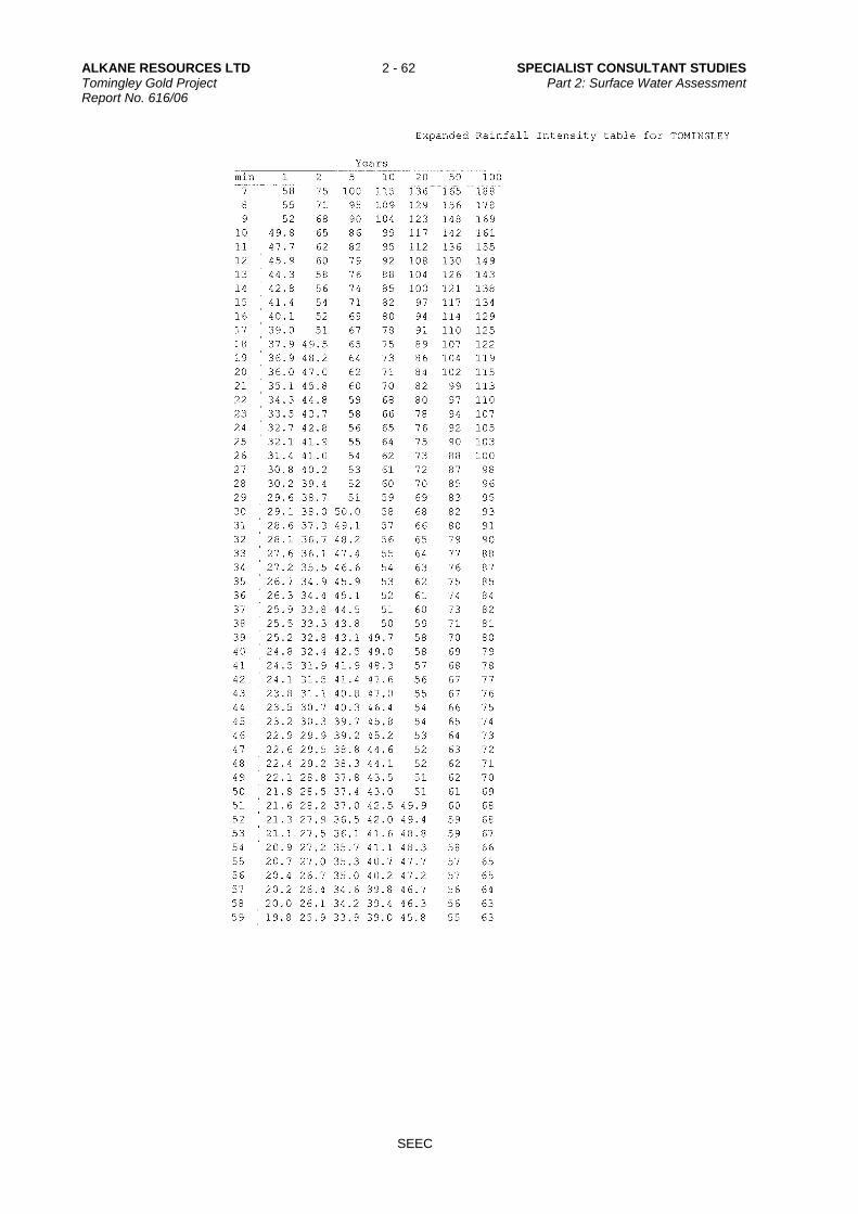
ALKANE RESOURCES LTD 2 - 62 SPECIALIST CONSULTANT STUDIES Tomingley Gold Project Part 2: Surface Water Assessment Report No. 616/06
SEEC

SPECIALIST CONSULTANT STUDIES 2 - 63 ALKANE RESOURCES LTD Part 2: Surface Water Assessment Tomingley Gold Project Report No. 616/06
SEEC
Appendix 2
Existing Culvert Design Check
(No. of pages including blank pages = 4)
(Note: A copy of Appendix 2 is provided on the Project CD)

ALKANE RESOURCES LTD 2 - 64 SPECIALIST CONSULTANT STUDIES Tomingley Gold Project Part 2: Surface Water Assessment Report No. 616/06
SEEC
This page has intentionally been left blank

SPECIALIST CONSULTANT STUDIES 2 - 65 ALKANE RESOURCES LTD Part 2: Surface Water Assessment Tomingley Gold Project Report No. 616/06
SEEC

ALKANE RESOURCES LTD 2 - 66 SPECIALIST CONSULTANT STUDIES Tomingley Gold Project Part 2: Surface Water Assessment Report No. 616/06
SEEC
This page has intentionally been left blank

SPECIALIST CONSULTANT STUDIES 2 - 67 ALKANE RESOURCES LTD Part 2: Surface Water Assessment Tomingley Gold Project Report No. 616/06
SEEC
Appendix 3
DRAINS Output Files and Cross-Sections
(No. of pages including blank pages = 10)
(Note: A copy of Appendix 3 is provided on the Project CD)

ALKANE RESOURCES LTD 2 - 68 SPECIALIST CONSULTANT STUDIES Tomingley Gold Project Part 2: Surface Water Assessment Report No. 616/06
SEEC
This page has intentionally been left blank

SPECIALIST CONSULTANT STUDIES 2 - 69 ALKANE RESOURCES LTD Part 2: Surface Water Assessment Tomingley Gold Project Report No. 616/06
SEEC

ALKANE RESOURCES LTD 2 - 70 SPECIALIST CONSULTANT STUDIES Tomingley Gold Project Part 2: Surface Water Assessment Report No. 616/06
SEEC

SPECIALIST CONSULTANT STUDIES 2 - 71 ALKANE RESOURCES LTD Part 2: Surface Water Assessment Tomingley Gold Project Report No. 616/06
SEEC

ALKANE RESOURCES LTD 2 - 72 SPECIALIST CONSULTANT STUDIES Tomingley Gold Project Part 2: Surface Water Assessment Report No. 616/06
SEEC

SPECIALIST CONSULTANT STUDIES 2 - 73 ALKANE RESOURCES LTD Part 2: Surface Water Assessment Tomingley Gold Project Report No. 616/06
SEEC

ALKANE RESOURCES LTD 2 - 74 SPECIALIST CONSULTANT STUDIES Tomingley Gold Project Part 2: Surface Water Assessment Report No. 616/06
SEEC

SPECIALIST CONSULTANT STUDIES 2 - 75 ALKANE RESOURCES LTD Part 2: Surface Water Assessment Tomingley Gold Project Report No. 616/06
SEEC

ALKANE RESOURCES LTD 2 - 76 SPECIALIST CONSULTANT STUDIES Tomingley Gold Project Part 2: Surface Water Assessment Report No. 616/06
SEEC

SPECIALIST CONSULTANT STUDIES 2 - 77 ALKANE RESOURCES LTD Part 2: Surface Water Assessment Tomingley Gold Project Report No. 616/06
SEEC
Appendix 4
RATES Modelling Outputs
(No. of pages including blank pages = 4)
(Note: A copy of Appendix 4 is provided on the Project CD)

ALKANE RESOURCES LTD 2 - 78 SPECIALIST CONSULTANT STUDIES Tomingley Gold Project Part 2: Surface Water Assessment Report No. 616/06
SEEC
This page has intentionally been left blank

SPECIALIST CONSULTANT STUDIES 2 - 79 ALKANE RESOURCES LTD Part 2: Surface Water Assessment Tomingley Gold Project Report No. 616/06
SEEC

ALKANE RESOURCES LTD 2 - 80 SPECIALIST CONSULTANT STUDIES Tomingley Gold Project Part 2: Surface Water Assessment Report No. 616/06
SEEC

SPECIALIST CONSULTANT STUDIES 2 - 81 ALKANE RESOURCES LTD Part 2: Surface Water Assessment Tomingley Gold Project Report No. 616/06
SEEC
Appendix 5
Sediment Basin Sizing Spreadsheet
(No. of pages including blank pages = 4)
(Note: A copy of Appendix 5 is provided on the Project CD)

ALKANE RESOURCES LTD 2 - 82 SPECIALIST CONSULTANT STUDIES Tomingley Gold Project Part 2: Surface Water Assessment Report No. 616/06
SEEC
This page has intentionally been left blank
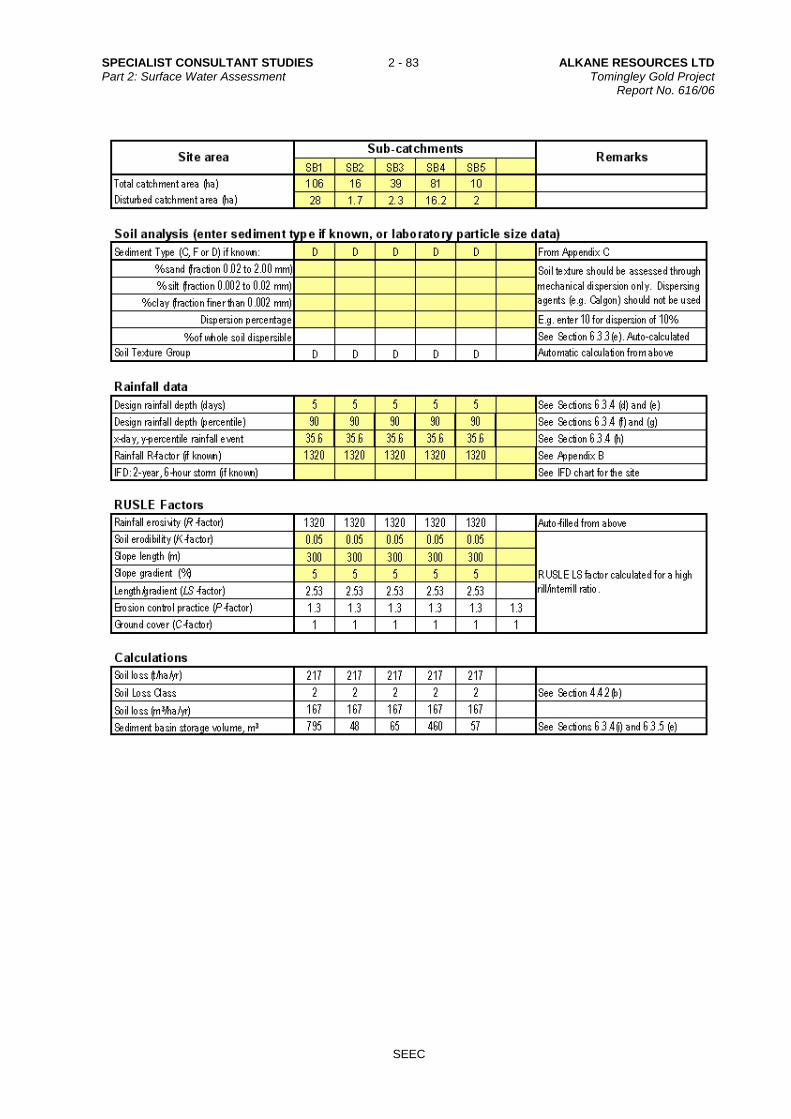
SPECIALIST CONSULTANT STUDIES 2 - 83 ALKANE RESOURCES LTD Part 2: Surface Water Assessment Tomingley Gold Project Report No. 616/06
SEEC

ALKANE RESOURCES LTD 2 - 84 SPECIALIST CONSULTANT STUDIES Tomingley Gold Project Part 2: Surface Water Assessment Report No. 616/06
SEEC
SPECIALIST CONSULTANT STUDIES 2 - 85 ALKANE RESOURCES LTD Part 2: Surface Water Assessment Tomingley Gold Project Report No. 616/06
SEEC
Appendix 6
Plans and HEC-RAS Output data for Proposed Gundong Creek Crossing
(No. of pages including blank pages = 8)
(Note: A copy of Appendix 6 is provided on the Project CD)

ALKANE RESOURCES LTD 2 - 86 SPECIALIST CONSULTANT STUDIES Tomingley Gold Project Part 2: Surface Water Assessment Report No. 616/06
SEEC
This page has intentionally been left blank

SPECIALIST CONSULTANT STUDIES 2 - 87 ALKANE RESOURCES LTD Part 2: Surface Water Assessment Tomingley Gold Project Report No. 616/06
SEEC

ALKANE RESOURCES LTD 2 - 88 SPECIALIST CONSULTANT STUDIES Tomingley Gold Project Part 2: Surface Water Assessment Report No. 616/06
SEEC

SPECIALIST CONSULTANT STUDIES 2 - 89 ALKANE RESOURCES LTD Part 2: Surface Water Assessment Tomingley Gold Project Report No. 616/06
SEEC

ALKANE RESOURCES LTD 2 - 90 SPECIALIST CONSULTANT STUDIES Tomingley Gold Project Part 2: Surface Water Assessment Report No. 616/06
SEEC

SPECIALIST CONSULTANT STUDIES 2 - 91 ALKANE RESOURCES LTD Part 2: Surface Water Assessment Tomingley Gold Project Report No. 616/06
SEEC
Photo 1 – Looking Upstream of Proposed Creek Crossing (GPS 613090,6394460)
Photo 2 – Looking Downstream of Proposed Creek Crossing (GPS 613052.5,6394417)

ALKANE RESOURCES LTD 2 - 92 SPECIALIST CONSULTANT STUDIES Tomingley Gold Project Part 2: Surface Water Assessment Report No. 616/06
SEEC
This page has intentionally been left blank

SPECIALIST CONSULTANT STUDIES 2 - 93 ALKANE RESOURCES LTD Part 2: Surface Water Assessment Tomingley Gold Project Report No. 616/06
SEEC
Appendix 7
New South Wales Office of Water Requirements for Controlled Activities
(No. of pages including blank pages = 4)
(Note: A copy of Appendix 7 is provided on the Project CD)

ALKANE RESOURCES LTD 2 - 94 SPECIALIST CONSULTANT STUDIES Tomingley Gold Project Part 2: Surface Water Assessment Report No. 616/06
SEEC
This page has intentionally been left blank

SPECIALIST CONSULTANT STUDIES 2 - 95 ALKANE RESOURCES LTD Part 2: Surface Water Assessment Tomingley Gold Project Report No. 616/06
SEEC
Coverage of NSW Office of Water Requirements for Controlled Activities
Paraphrased Requirement Relevant Section of This Report
Watercourse Crossings & In-stream Works
The design and construction of crossing structures should consider, but not limited to, the following principles.
Identify the width of the riparian corridor in accordance with the NSW Office of Water’s Guidelines for riparian corridors.
Section 7.3.2
Consider the full width of the riparian corridor and its functions in the design and construction of crossings. Where possible the design should accommodate fully structured native vegetation.
Section 7.3.5.1
Minimise the design and construction footprint and extent of proposed disturbances within the watercourse and riparian corridor.
Section 7.3.5.1
Maintain existing or natural hydraulic, hydrologic, geomorphic and ecological functions of the watercourse.
Appendix 6
Demonstrate that where a raised structure or increase in the height of the bed is proposed there will be no detrimental impacts on the natural hydraulic, hydrologic, geomorphic and ecological functions.
Appendix 6
Maintain natural geomorphic processes:
accommodate natural watercourse functions
maintain the natural bed and bank profile
ensure the movement of sediment and woody debris is not inhibited
do not increase scour and erosion of the bed or banks in any storm events
avoid locating structures on bends in the channel
where bed degradation has occurred, address bed degradation to protect the structure and restore channel and bed stability.
Section 7.3.5.1
Maintain natural hydrological regimes:
accommodate site hydrological conditions
do not alter natural bank full or floodplain flows or increase water levels upstream
do not change the gradient of the bed except where necessary to address existing bed and bank degradation
do not increase velocities by constricting flows, for example filled embankments on approaches.
Section 7.3.5.1
Protect against scour:
provide any necessary scour protection, such as rock rip-rap and vegetation
ensure scour protection of the bed and banks downstream of the structure is extended for a distance of either twice the channel width or 20 metres whichever is the lesser
if cutting into banks, protect cuttings against scour.
Section 7.3.5.1 & Appendix 6
Stabilise and rehabilitate all disturbed areas including topsoiling, revegetation, mulching, weed control and maintenance in order to adequately restore the integrity of the riparian corridor.
Section 7.3.5.1

ALKANE RESOURCES LTD 2 - 96 SPECIALIST CONSULTANT STUDIES Tomingley Gold Project Part 2: Surface Water Assessment Report No. 616/06
SEEC
Coverage of NSW Office of Water Requirements for Controlled Activities
Paraphrased Requirement Relevant Section of This Report
Watercourse Crossings & Instream Works
Identify alternative options and detail the reasons for selecting the preferred option/s.
Monitor and maintain all in-stream works until suitably stabilised. Section 7.3.5.1 Other Additional Information:
Detailed design drawings of proposed works Appendix 6
Detailed design drawings which include a surveyed plan, cross sections (across the watercourse) and a long section of the watercourse, showing the proposed works relative to existing and proposed bed and bank profiles and water levels. The cross section should extend to the landward limit of the identified riparian corridor. All plans MUST include a scale bar.
Appendix 6
Detailed report of pre and post construction hydraulic conditions. The report should address bank full discharge, velocity, tractive force or sheer stress, afflux (Modified RTA method is acceptable), Froude and Manning’s ‘n’ roughness values, relative to the proposed structure.
Appendix 6
Detailed plans of permanent bed and bank stabilisation works for scour protection.
Appendix 6
Photographs of the site. To assist with future monitoring and reporting, all photo points should be identified by GPS coordinates or by survey
Appendix 6
A Vegetation Management Plan prepared in accordance with NSW Office of Water’s Guidelines for Vegetation Management Plans.
Note 1, below
Sediment and erosion control plan. Note 1, below
A site management plan incorporating a works schedule, sequence and duration of works, contingencies (in case of flood etc), erosion and sediment controls and proposed monitoring and reporting periods.
Note 1, below
Costing of all works (materials, labour) and stages of works (channel stabilisation, rehabilitation, etc).
Note 1, below
Copies of other relevant approvals for example land owner’s consent or development consent.
Note 1, below
Culverts – additional design requirements.
Box culverts are preferred to pipes. Section 7.3.5.1
Align culverts with downstream channel. Section 7.3.5.1
Incorporate elevated ‘dry cells’ and recessed ‘wet cells’ with the invert at or below the stable bed level.
Section 7.3.5.1
Maintain existing or natural hydraulic, hydrologic, geomorphic and ecological functions of the watercourse.
Section 7.3.5.1 & Appendix 6
The culvert design must be certified by a suitably qualified engineer. Note 1, below
Note 1 – Details to be submitted with the formal submission of application for Approval of a Controlled
Work.

SPECIALIST CONSULTANT STUDIES 2 - 97 ALKANE RESOURCES LTD Part 2: Surface Water Assessment Tomingley Gold Project Report No. 616/06
SEEC
Appendix 8
Water Sampling Results
(No. of pages including blank pages = 20)
(Note: A copy of Appendix 8 is provided on the Project CD)

ALKANE RESOURCES LTD 2 - 98 SPECIALIST CONSULTANT STUDIES Tomingley Gold Project Part 2: Surface Water Assessment Report No. 616/06
SEEC
This page has intentionally been left blank

SPECIALIST CONSULTANT STUDIES 2 - 99 ALKANE RESOURCES LTD Part 2: Surface Water Assessment Tomingley Gold Project Report No. 616/06
SEEC

ALKANE RESOURCES LTD 2 - 100 SPECIALIST CONSULTANT STUDIES Tomingley Gold Project Part 2: Surface Water Assessment Report No. 616/06
SEEC
SPECIALIST CONSULTANT STUDIES 2 - 101 ALKANE RESOURCES LTD Part 2: Surface Water Assessment Tomingley Gold Project Report No. 616/06
SEEC

ALKANE RESOURCES LTD 2 - 102 SPECIALIST CONSULTANT STUDIES Tomingley Gold Project Part 2: Surface Water Assessment Report No. 616/06
SEEC

SPECIALIST CONSULTANT STUDIES 2 - 103 ALKANE RESOURCES LTD Part 2: Surface Water Assessment Tomingley Gold Project Report No. 616/06
SEEC

ALKANE RESOURCES LTD 2 - 104 SPECIALIST CONSULTANT STUDIES Tomingley Gold Project Part 2: Surface Water Assessment Report No. 616/06
SEEC
SPECIALIST CONSULTANT STUDIES 2 - 105 ALKANE RESOURCES LTD Part 2: Surface Water Assessment Tomingley Gold Project Report No. 616/06
SEEC

ALKANE RESOURCES LTD 2 - 106 SPECIALIST CONSULTANT STUDIES Tomingley Gold Project Part 2: Surface Water Assessment Report No. 616/06
SEEC

SPECIALIST CONSULTANT STUDIES 2 - 107 ALKANE RESOURCES LTD Part 2: Surface Water Assessment Tomingley Gold Project Report No. 616/06
SEEC

ALKANE RESOURCES LTD 2 - 108 SPECIALIST CONSULTANT STUDIES Tomingley Gold Project Part 2: Surface Water Assessment Report No. 616/06
SEEC

SPECIALIST CONSULTANT STUDIES 2 - 109 ALKANE RESOURCES LTD Part 2: Surface Water Assessment Tomingley Gold Project Report No. 616/06
SEEC

ALKANE RESOURCES LTD 2 - 110 SPECIALIST CONSULTANT STUDIES Tomingley Gold Project Part 2: Surface Water Assessment Report No. 616/06
SEEC

SPECIALIST CONSULTANT STUDIES 2 - 111 ALKANE RESOURCES LTD Part 2: Surface Water Assessment Tomingley Gold Project Report No. 616/06
SEEC

ALKANE RESOURCES LTD 2 - 112 SPECIALIST CONSULTANT STUDIES Tomingley Gold Project Part 2: Surface Water Assessment Report No. 616/06
SEEC
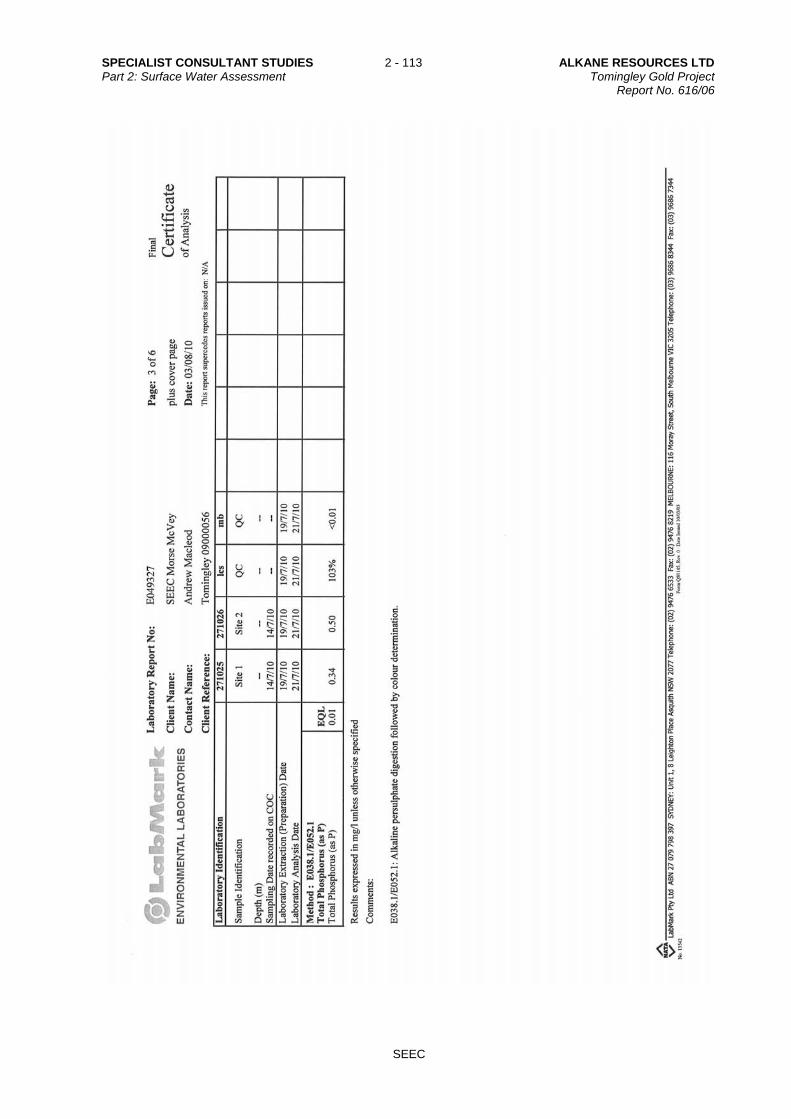
SPECIALIST CONSULTANT STUDIES 2 - 113 ALKANE RESOURCES LTD Part 2: Surface Water Assessment Tomingley Gold Project Report No. 616/06
SEEC

ALKANE RESOURCES LTD 2 - 114 SPECIALIST CONSULTANT STUDIES Tomingley Gold Project Part 2: Surface Water Assessment Report No. 616/06
SEEC

SPECIALIST CONSULTANT STUDIES 2 - 115 ALKANE RESOURCES LTD Part 2: Surface Water Assessment Tomingley Gold Project Report No. 616/06
SEEC
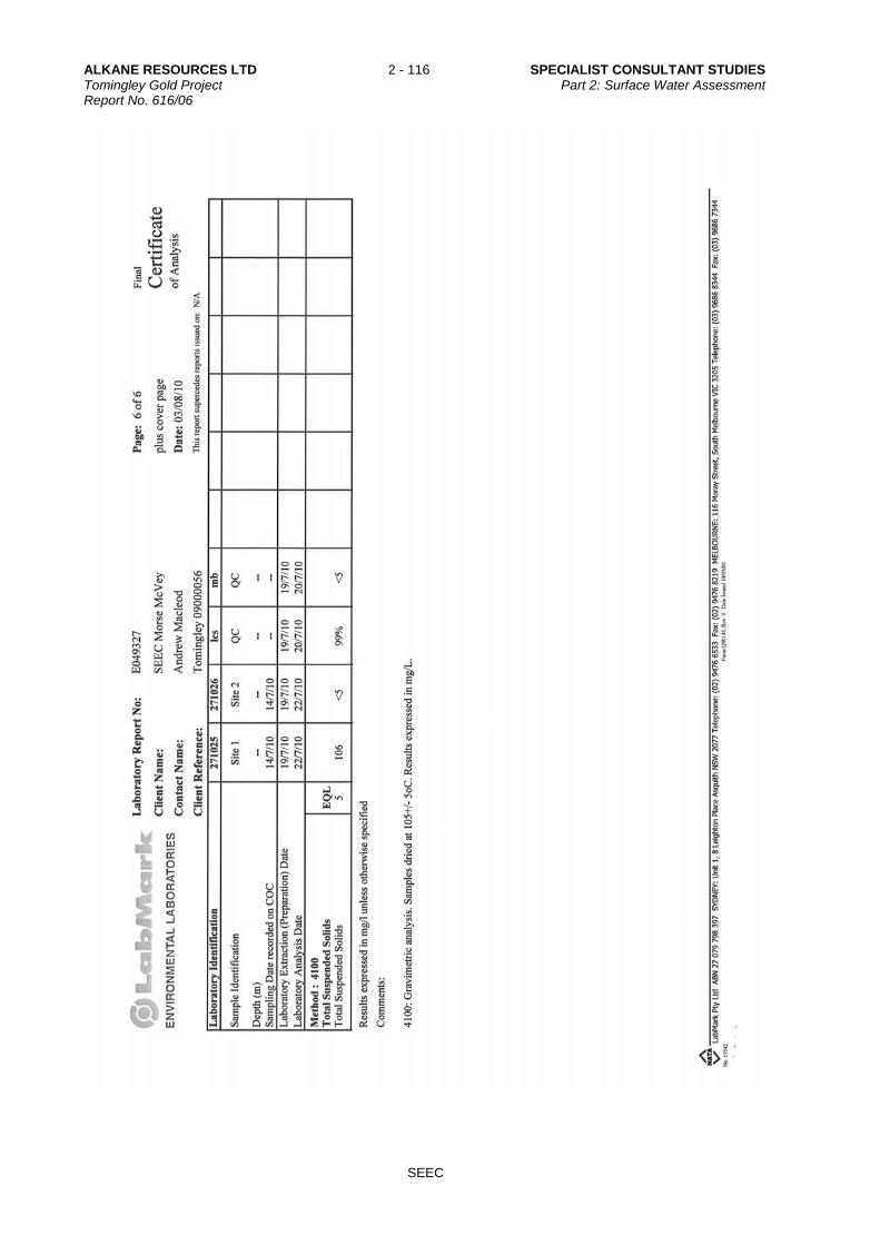
ALKANE RESOURCES LTD 2 - 116 SPECIALIST CONSULTANT STUDIES Tomingley Gold Project Part 2: Surface Water Assessment Report No. 616/06
SEEC

SPECIALIST CONSULTANT STUDIES 2 - 117 ALKANE RESOURCES LTD Part 2: Surface Water Assessment Tomingley Gold Project Report No. 616/06
SEEC
Appendix 9
Director-General’s Requirements
(No. of pages including blank pages = 10)

ALKANE RESOURCES LTD 2 - 118 SPECIALIST CONSULTANT STUDIES Tomingley Gold Project Part 2: Surface Water Assessment Report No. 616/06
SEEC
This page has intentionally been left blank

SPECIALIST CONSULTANT STUDIES 2 - 119 ALKANE RESOURCES LTD Part 2: Surface Water Assessment Tomingley Gold Project Report No. 616/06
SEEC
Coverage of Director-General’s Requirements in the Environmental Assessment Page 1 of 7
Government Agency Paraphrased Requirement
Relevant Section of This Report
GENERAL
Soil and Water – including:
a detailed site water balance; Section 5.6
a detailed groundwater model; N/A
potential water quality impacts on the environment and other land users, including a geochemical assessment of the potential leachate impacts; and
Sections 6.4 and 6.7
a description of final void water management; Refer to EA
WATER
DECCW Provide details of the project that are essential for predicting and assessing impacts to waters:
a) including the quantity and physio-chemical properties of all potential water pollutants and the risks they pose to the environment and human health, including the risks they pose to Water Quality Objectives in the ambient waters (as defined on www.environment.nsw.gov.au/ieo, using technical criteria derived from the Australian and New Zealand Guidelines for Fresh and Marine Water Quality, ANZECC 2000)
Sections 5.3, 6.4 and 6.7
b) the management of discharges with potential for water impacts
Section 7.3.1
c) drainage works and associated infrastructure; land forming and excavations; working capacity of structures; and water resource requirements of the proposal.
Sections 5.6, 7.3.1, 7.3.2 and 7.3.3
Outline site layout, demonstrating efforts to avoid proximity to water resources (especially for activities with significant potential impacts eg effluent ponds) and showing potential areas of modification of contours, drainage etc.
Sections 5 and 6
Outline how total water cycle considerations are to be addresses showing total water balances for the development (with the objective of minimising demands and impacts on water resources). Include water requirements (quantity, quality and source(s)) and proposed storm and wastewater disposal, including type, volumes, proposed treatment and management methods and re-use options.
Sections 5.6 and 7
Describe the catchment including proximity of the development to any waterways and provide an assessment of their sensitivity/significance from a public health, ecological and/or economic perspective. The Water Quality and River Flow Objectives on the website: www.environment.nsw.gov.au/ieo should be used to identify the agreed environmental values and human uses for any affected waterways. This will help with the description of the local and regional area.
Sections 4.4 and 6.7
Describe existing surface and groundwater quality – an assessment needs to be undertaken for any water resource likely to be affected by the proposal and for all conditions (eg. a wet weather sampling program is needed if runoff events may cause impacts).
Sections 5.3 and 5.5, plus the Groundwater
Assessment

ALKANE RESOURCES LTD 2 - 120 SPECIALIST CONSULTANT STUDIES Tomingley Gold Project Part 2: Surface Water Assessment Report No. 616/06
SEEC
Coverage of Director-General’s Requirements in the Environmental Assessment Page 2 of 7
Government Agency Paraphrased Requirement
Relevant Section of This Report
WATER
DECCW Provide site drainage details and surface runoff yield. Sections 5.1 and 5.2
State the ambient Water Quality and River Flow Objectives for the receiving waters. These refer to the community's agreed environmental values and human uses endorsed by the Government as goals for the ambient waters. These environmental values are published on the website: www.environment.nsw.gov.au/ieo. The EIS should state the environmental values listed for the catchment and waterway type relevant to your proposal. NB: A consolidated and approved list of environmental values are not available for groundwater resources. Where groundwater may be affected the EIS should identify appropriate groundwater environmental values and justify the choice.
Section 6.7
State the indicators and associated trigger values or criteria for the identified environmental valuer This information should be sourced from the ANZECC 2000 Guidelines for Fresh and Marine Water Quality (http://www.deh.gov.au/water/quality/nwqms/volume1.html) (Note that, as at 2004, the NSW Water Quality Objectives booklets and website contain technical criteria derived from the 1992 version of the ANZECC Guidelines. The Water Quality Objectives remain as Government Policy, reflecting the community's environmental values and long-term goals, but the technical criteria are replaced by the more recent ANZECC 2000 Guidelines). NB: While specific guidelines for groundwater are not available, the ANCECC 2000 Guidelines endorse the application of the trigger values and decision trees as a tool to assess risk to environmental values in groundwater.
Section 6.7
State any locally specific objectives, criteria or targets, which have been endorsed by the government, eg. the Healthy Rivers Commission Inquiries (www.hrc.nsw.gov.au) or the NSW Salinity Strategy (DLWC, 2000) (www.dlwc.nsw.gov.au/care/salinity/#Strategy).
N/A
Where site specific studies are proposed to revise the trigger values supporting the ambient Water Quality and River Flow Objectives, and the results are to be used for regulatory purposes (eg. to assess whether a licensed discharge impacts on water quality objectives), then prior agreement from the DECCW on the approach and study design must be obtained.
N/A
Describe the state of the receiving waters and relate this to the relevant Water Quality and River Flow Objectives (ie. are Water Quality and River Flow Objectives being achieved?). Proponents are generally only expected to source available data and information. However, proponents of large or high risk developments may be required to collect some ambient water quality / river flow / groundwater data to enable a suitable level of impact assessment. Issues to include in the description of the receiving waters could include:
Section 5.3 and 6.7

SPECIALIST CONSULTANT STUDIES 2 - 121 ALKANE RESOURCES LTD Part 2: Surface Water Assessment Tomingley Gold Project Report No. 616/06
SEEC
Coverage of Director-General’s Requirements in the Environmental Assessment Page 3 of 7
Government Agency Paraphrased Requirement
Relevant Section of This Report
WATER
DECCW a) lake or estuary flushing characteristics
b) specific human uses (eg. exact location of drinking water offtake)
c) sensitive ecosystems or species conservation values
d) a description of the condition of the local catchment eg. erosion levels, soils, vegetation cover, etc
e) an outline of baseline groundwater information, including, but not restricted to, depth to watertable, flow direction and gradient, groundwater quality, reliance on groundwater by surrounding users and by the environment
f) historic river flow data where available for the catchment.
No proposal should breach clause 120 of the Protection of the Environment Operations Act 1997 (ie. pollution of waters is prohibited unless undertaken in accordance with relevant regulations).
N/A
Identify and estimate the quantity of all pollutants that may be introduced into the water cycle by source and discharge point including residual discharges after mitigation measures are implemented.
Sections 5.3 and 6.4
Include a rationale, along with relevant calculations, supporting the prediction of the discharges.
Sections 5.3 and 6.4
Describe the effects and significance of any pollutant loads on the receiving environment. This should include impacts of residual discharges through modelling, monitoring or both, depending on the scale of the proposal. Determine changes to hydrology (including drainage patterns, surface runoff yield, flow regimes, wetland hydrologic regimes and groundwater).
Sections 5 and 6
Describe water quality impacts resulting from changes to hydrologic flow regimes (such as nutrient enrichment or turbidity resulting from changes in frequency and magnitude of stream flow).
Sections 6.4 and 6.7
Identify any potential impacts on quality or quantity of groundwater describing their source.
N/A
Identify potential impacts associated with geomorphological activities with potential to increase surface water and sediment runoff or to reduce surface runoff and sediment transport. Also consider possible impacts such as bed lowering, bank lowering, instream siltation, floodplain erosion and floodplain siltation.
Sections 5 and 6
Identify impacts associated with the disturbance of acid sulfate soils and potential acid sulfate soils.
Section 4.3
Containment of spills and leaks shall be in accordance with the technical guidelines section 'Bunding and Spill Management' of the Authorised Officers Manual (EPA, 1995) (http://www.environment.nsw.gov.au/mao/bundingspill.htm) and the most recent versions of the Australian Standards referred to in the Guidelines. Containment should be designed for no-discharge.
Section 7
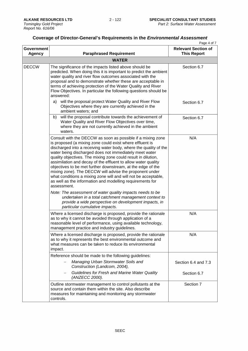
ALKANE RESOURCES LTD 2 - 122 SPECIALIST CONSULTANT STUDIES Tomingley Gold Project Part 2: Surface Water Assessment Report No. 616/06
SEEC
Coverage of Director-General’s Requirements in the Environmental Assessment Page 4 of 7
Government Agency Paraphrased Requirement
Relevant Section of This Report
WATER
DECCW The significance of the impacts listed above should be predicted. When doing this it is important to predict the ambient water quality and river flow outcomes associated with the proposal and to demonstrate whether these are acceptable in terms of achieving protection of the Water Quality and River Flow Objectives. In particular the following questions should be answered:
Section 6.7
a) will the proposal protect Water Quality and River Flow Objectives where they are currently achieved in the ambient waters; and
Section 6.7
b) will the proposal contribute towards the achievement of Water Quality and River Flow Objectives over time, where they are not currently achieved in the ambient waters.
Section 6.7
Consult with the DECCW as soon as possible if a mixing zone is proposed (a mixing zone could exist where effluent is discharged into a receiving water body, where the quality of the water being discharged does not immediately meet water quality objectives. The mixing zone could result in dilution, assimilation and decay of the effluent to allow water quality objectives to be met further downstream, at the edge of the mixing zone). The DECCW will advise the proponent under what conditions a mixing zone will and will not be acceptable, as well as the information and modelling requirements for assessment.
Note: The assessment of water quality impacts needs to be undertaken in a total catchment management context to provide a wide perspective on development impacts, in particular cumulative impacts.
N/A
Where a licensed discharge is proposed, provide the rationale as to why it cannot be avoided through application of a reasonable level of performance, using available technology, management practice and industry guidelines.
N/A
Where a licensed discharge is proposed, provide the rationale as to why it represents the best environmental outcome and what measures can be taken to reduce its environmental impact.
N/A
Reference should be made to the following guidelines:
Managing Urban Stormwater Soils and Construction (Landcom, 2004),
Section 6.4 and 7.3
Guidelines for Fresh and Marine Water Quality (ANZECC 2000).
Section 6.7
Outline stormwater management to control pollutants at the source and contain them within the site. Also describe measures for maintaining and monitoring any stormwater controls.
Section 7

SPECIALIST CONSULTANT STUDIES 2 - 123 ALKANE RESOURCES LTD Part 2: Surface Water Assessment Tomingley Gold Project Report No. 616/06
SEEC
Coverage of Director-General’s Requirements in the Environmental Assessment Page 5 of 7
Government Agency Paraphrased Requirement
Relevant Section of This Report
WATER
DECCW Outline erosion and sediment control measures directed at minimising disturbance of land, minimising water flow through the site and filtering, trapping or detaining sediment. Also include measures to maintain and monitor controls as well as rehabilitation strategies.
Section 7
Describe waste water treatment measures that are appropriate to the type and volume of waste water and are based on a hierarchy of avoiding generation of waste water; capturing all contaminated water (including stormwater) on the site; reusing/recycling waste water; and treating any unavoidable discharge from the site to meet specified water quality requirements.
Sections 5.6, 6.6 and 7.3.4
Outline pollution control measures relating to storage of materials, possibility of accidental spills (e.g. preparation of contingency plans), appropriate disposal methods, and generation of leachate.
See comments in EA
Describe hydrological impact mitigation measures including: Sections 4, 5 and 6
a) site selection (avoiding sites prone to flooding and waterlogging, actively eroding or affected by deposition)
b) minimising runoff
c) minimising reductions or modifications to flow regimes
d) avoiding modifications to groundwater.
Describe groundwater impact mitigation measures including: N/A
a) site selection
b) retention of native vegetation and revegetation
c) artificial recharge
d) providing surface storages with impervious linings
e) monitoring program.
Describe geomorphological impact mitigation measures including:
Sections 6 and 7
a) site selection
b) erosion and sediment controls
c) minimising instream works
(i) treating existing accelerated erosion and deposition
(ii) monitoring program.
Any proposed monitoring should be undertaken in accordance with the Approved Methods for the Sampling and Analysis of Water Pollutants in NSW (DECCW 2004).
Sections 5.5 and 7.4
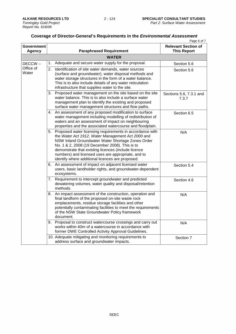
ALKANE RESOURCES LTD 2 - 124 SPECIALIST CONSULTANT STUDIES Tomingley Gold Project Part 2: Surface Water Assessment Report No. 616/06
SEEC
Coverage of Director-General’s Requirements in the Environmental Assessment Page 6 of 7
Government Agency Paraphrased Requirement
Relevant Section of This Report
WATER
DECCW – Office of Water
1. Adequate and secure water supply for the proposal. Section 5.6
2. Identification of site water demands, water sources (surface and groundwater), water disposal methods and water storage structures in the form of a water balance. This is to also include details of any water reticulation infrastructure that supplies water to the site.
Section 5.6
3. Proposed water management on the site based on the site water balance. This is to also include a surface water management plan to identify the existing and proposed surface water management structures and flow paths.
Sections 5.6, 7.3.1 and 7.3.7
4. An assessment of any proposed modification to surface water management including modelling of redistribution of waters and an assessment of impact on neighbouring properties and the associated watercourse and floodplain.
Section 6.5
5. Proposed water licensing requirements in accordance with the Water Act 1912, Water Management Act 2000 and NSW Inland Groundwater Water Shortage Zones Order No. 1 & 2, 2008 (19 December 2008). This is to demonstrate that existing licences (include licence numbers) and licensed uses are appropriate, and to identify where additional licences are proposed.
N/A
6. An assessment of impact on adjacent licensed water users, basic landholder rights, and groundwater-dependent ecosystems.
Section 5.4
7. Requirement to intercept groundwater and predicted dewatering volumes, water quality and disposal/retention methods.
Section 4.6
8. An impact assessment of the construction, operation and final landform of the proposed on-site waste rock emplacements, residue storage facilities and other potentially contaminating facilities to meet the requirements of the NSW State Groundwater Policy framework document.
N/A
9. Proposal to construct watercourse crossings and carry out works within 40m of a watercourse in accordance with former DWE Controlled Activity Approval Guidelines.
N/A
10. Adequate mitigating and monitoring requirements to address surface and groundwater impacts.
Section 7

SPECIALIST CONSULTANT STUDIES 2 - 125 ALKANE RESOURCES LTD Part 2: Surface Water Assessment Tomingley Gold Project Report No. 616/06
SEEC
Coverage of Director-General’s Requirements in the Environmental Assessment Page 7 of 7
Government Agency Paraphrased Requirement
Relevant Section of This Report
WATER
DECCW – Office of Water
General EA Assessment Requirements
General Environmental Risk Analysis – the EA must include the following for all water-related aspects of the proposal:
an environmental risk analysis to identify potential environmental impacts associated with the project (construction and operation);
Sections 6 and 7
proposed mitigation measures and potentially significant residual environmental impacts after the application of proposed mitigation measures; and
where additional key environmental impacts are identified through this environmental risk analysis, an appropriately detailed impact assessment of these additional key environmental impacts must be included in the EA.
Key issue: Water supply and water balance
The EA must include assessment of water supply and/or water interception and extraction against any Water Sharing Plan and water licences affecting the site or potential water supply to the proposal. A full description of water supply to all stages of the proposal must be included, which includes:
Section 5.6
water source(s) which may be used to supply water to the proposal, existing licences, additional water requirements, and a checklist against any regulatory water sharing or other ministerial plans or other instruments applying to that water source
explanation of any embargoes or full commitment declarations for the proposal, and any identified means to source water supply for the proposal
examination of reliability of water supply to the proposal, including alternatives to site rainfall runoff harvesting in the event of drought
demonstration of prioritisation and effective reuse of saline or other contaminated water within the proposal
explanation of water circuitry and means to segregate contaminated, sediment-laden and clean water volumes within the proposal and proposal site. This would require development of surface water management plan.

ALKANE RESOURCES LTD 2 - 126 SPECIALIST CONSULTANT STUDIES Tomingley Gold Project Part 2: Surface Water Assessment Report No. 616/06
SEEC
This page has intentionally been left blank