Tomakomai CCS Demonstration Project of Japan, with CO2 ... Tanaka... · 10 Copyright 2017 Japan CCS...
20
1 Copyright 2017 Japan CCS Co., Ltd. 1 Tomakomai CCS Demonstration Project of Japan, with CO 2 Injection in Process Gastech 201 7 April 4, 2017 Japan CCS Co., Ltd. (JCCS)
Transcript of Tomakomai CCS Demonstration Project of Japan, with CO2 ... Tanaka... · 10 Copyright 2017 Japan CCS...

1
Copyright 2017 Japan CCS Co., Ltd.
1
Tomakomai CCS Demonstration Project
of Japan,
with CO2 Injection in Process
Gastech 2017
April 4, 2017
Japan CCS Co., Ltd. (JCCS)
2
Copyright 2017 Japan CCS Co., Ltd.
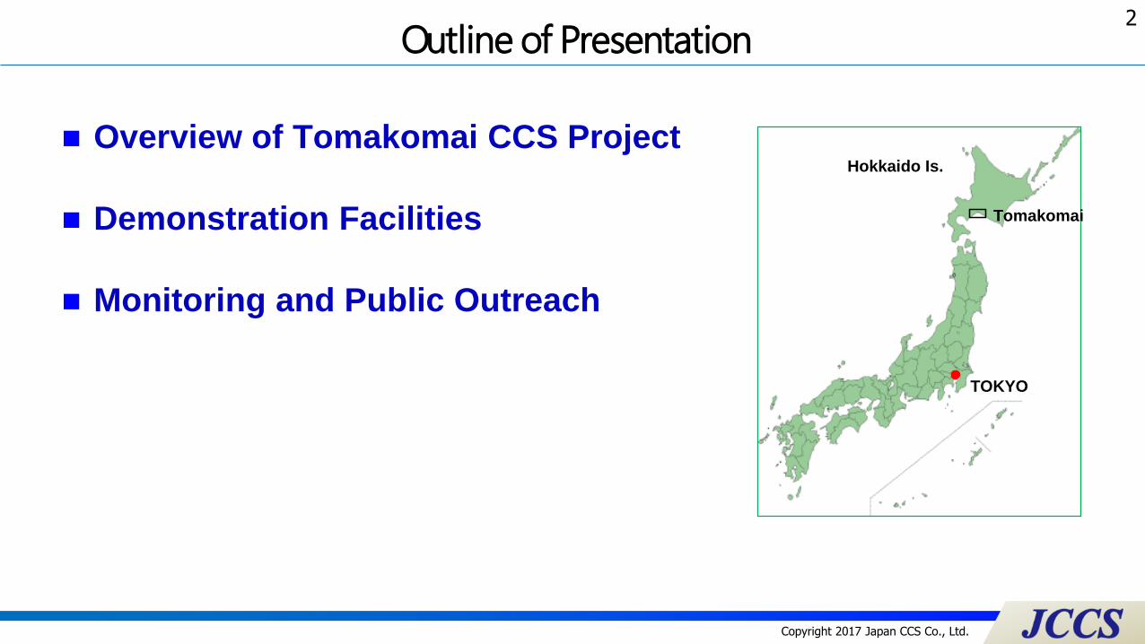
Outline of Presentation
Overview of Tomakomai CCS Project
Demonstration Facilities
Monitoring and Public Outreach
Hokkaido Is.
Tomakomai
TOKYO

3
Copyright 2017 Japan CCS Co., Ltd.
AA
Projects / FY 2015 2016 2017 2018 2019 2020~
A
Con-
struction
CO2 Injection
0.1 ~ 0.2 Mt/year
Post Injection
Monitoring
(2) CO2 Capture Technologies
Tomakomai
Demo Pj.
Practical use of
CCS tech.
Drilling Exploration wells
CCS Site Survey
Geological Survey
A(1) Safety Evaluation Technologies
Verifying Safety Evaluation Technologies
Cost Reduction
Identifying
CO2 Storage Site
Achieving
Operation
Abilities
Confirming CCS safety
Aiming at the practical use of CCS technology around 2020,METI conducts Tomakomai Demonstration Project, R&D projects ofelemental technologies for CCS, and survey for potential CO2 storage site.
R&Ds
Source: Ministry of Economy, Trade and Industry (Japan)
Overview of CCS Project in Japan
Overview of Tomakomai CCS Project
4
Copyright 2017 Japan CCS Co., Ltd.
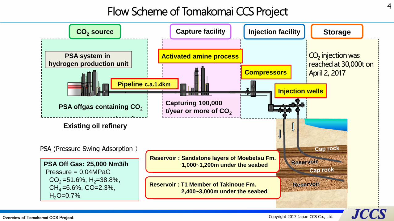
Flow Scheme of Tomakomai CCS Project
Compressor
CO2 source
PSA off gas containing
CO2 corresponding to
more than 100,000 t/year
Injection wells
Pipeline, approx. 2.5km
PSA
(Hydrogen production unit)
Capture facility
Reservoir : Sandstone layers of Moebetsu Fm.
1,000~1,200m under the seabed
Existing oil refinery
Injection facility
Capturing CO2 of more
than 100,000 t/year
Activated amine process
Reservoir : T1 Menber of Takinoue Fm.
2,400~3,000m under the seabed
Pipeline c.a.1.4km
Reservoir : Sandstone layers of Moebetsu Fm.
1,000~1,200m under the seabed
Reservoir : T1 Member of Takinoue Fm.
2,400~3,000m under the seabed
PSA offgas containing CO2
PSA system in
hydrogen production unit
Capturing 100,000
t/year or more of CO2
Activated amine process
Compressors
Injection wells
PSA (Pressure Swing Adsorption )
PSA Off Gas: 25,000 Nm3/h
Pressure = 0.04MPaG
CO2 =51.6%, H2=38.8%,
CH4 =6.6%, CO=2.3%,
H2O=0.7%
Overview of Tomakomai CCS Project
CO2 injection was
reached at 30,000t on
April 2, 2017
Storage

5
Copyright 2017 Japan CCS Co., Ltd.
Positional Relation of Injection & Monitoring Systems
OBC
Working area of 3D seismic survey
OBC (Ocean Bottom Cable): used for 2D seismic survey and monitoring of micro-seismicity and natural earthquakes.
OBS
OBS
OBS
OBS
Onshore Seismometer
Observation well OB-1 for Takinoue Form.converted from survey well (deviated)
Observation well OB-2 for Moebetsu Form. (vertical)
0 1 2 3 4 5km
Image: LC81070302016141LGN00, courtesy of the U.S. Geological Survey, text by JCCS
OBS (Ocean Bottom Seismometer): used for monitoring of micro-seismicity and natural earthquakes.
Observation well OB-3 for Takinoue Form.(vertical)
Overview of Tomakomai CCS Project

6
Copyright 2017 Japan CCS Co., Ltd.
Operation Schedule
FY2016 FY2017 FY2018 FY2019 FY2020
SU
RF
AC
EFA
CIL
ITIE
SIN
JE
CT
ION
WE
LL
SM
ON
ITO
RIN
G F
AC
ILIT
IES
ON
SH
OR
EO
FFSH
OR
E
As of April 2017
(*)-1 2D・3D Seismic Survey: survey method utilizing seismic reflection waves discharged from a seismic source of a seismic exploration vessel in order to delineate the subsea geological structure and/or formation characteristics. In this case, the data acquired is used to estimate the CO2 storage distribution by 2D cross sections or arbitrary panel diagrams in 3D space.
InjectionTEST
Operation (CO2 Separation/Injection)
Observation (Observation Well OB-1~3)
Observation (Onshore Seismometer)
Observation (OBC, OBS)
Marine Environmental Survey (Seasonal) (Current, Water Quality, Seabottom Conditions, Marine Life, etc.)
(Temperature, Pressure, Natural Earthquakes, Micro-seismicity)
2D Seismic Survey(*)-1
3D Seismic Survey(*)-1
(Natural Earthquakes, Micro-seismicity)
(Natural Earthquakes, Micro-seismicity)
2D Seismic Survey 2D Seismic Survey3D Seismic Survey
Overview of Tomakomai CCS Project

7
Copyright 2017 Japan CCS Co., Ltd.
Bird’s Eye View of Capture and Injection Facilities
Demonstration Facilities
Flare / vent stack CO2 absorption tower
CO2 stripping tower
Low pressure flash tower
PSA off gas compressor
LP steam boiler
Cooling tower
Pure water production
system
Industrial water intake pit
Waste water treatment pit
Control building
Steam turbine generator
High pressure
CO2 compressor
Secondary low pressure CO2
compressor
Primary low pressure
CO2 compressor
Amine tank
Injection wells
HP steam boiler
Fuel oil tank
Nitrogen supply system
CO2
From CO2
Source
Pure water tank
Instrument air supply
system

8
Copyright 2017 Japan CCS Co., Ltd.
Tomakomai CCS project CO2 Capture Process
CO2 Rich amine
CO2-lean gas
CO2
CO2
CO2 Semi-lean amine
CO2-containing
gas
Heat
CO2 Lean amine
CO2 Semi-lean amine
CO2 Absorption
Tower
CO2 Stripping
Tower
Low-pressure
Flash Tower (LPFT)
• In LPFT, CO2 is stripped by depressurization; thermal energy of water
vapor of CO2 Stripping Tower is also utilized to strip CO2
• Greater part of semi-lean amine from LPFT is returned to CO2 Absorption
Tower for CO2 absorption; as only the remaining smaller portion is sent to
CO2 Stripping Tower, reboiler heat required can be reduced
If pressure of gas containing CO2 and
partial pressure of CO2 are relatively high,
amine reboiler heat consumption is only
1/3~1/2 of conventional capture process
Proprietary Activated MDEA
was provided by B ASF
reboiler heat(steam) consumption =
0.92 GJ/t-CO2
(Tomakomai data obtained at commissioning)
(See note)
Note : total energy consumption for CO2 capture = [reboiler heat(steam)
consumption / steam boiler efficiency + pump electricity consumption x
electricity-heat conversion factor / power generation efficiency] / CO2 flow
rate = 1.22 GJ/t-CO2 or less (Tomakomai data obtained at commissioning)
Demonstration Facilities
CO2
CO2 Rich
amine
CO2-lean gasCO2
Stripping
Tower
CO2 Lean amine
Heat
Conventional CO2 Capture
Process
CO2
Absorption
Tower
CO2
gas

9
Copyright 2017 Japan CCS Co., Ltd.
Schematic Geological Section
Reservoir
Cap rock
※Aspect Ratio=1:1
Injection Well for
Moebetsu Fm.
Injection Well for
Takinoue Fm.
(projected)
Cap rock
Reservoir
Landward(North) Seaward(South)
T1 Member of Takinoue Fm. (Volcanic Rocks)
Fureoi Fm. (Mudstone)
Quaternary sediments
Moebetsu Fm. (Mudstone)
Takinoue Fm. (Mudstone)
Nina Fm. (Mudstone)
Moebetsu Fm. (Sandstone)
Mukawa Fm. (Sandstone, Mudstone, etc.)
Biratori-Karumai Fm. (Mudstone)
Depth
in m
ete
rs (
bM
SL)
(TD 5,800m)
(TD 3,650m)
Observation Well
for Moebetsu Fm.
Demonstration Facilities
10
Copyright 2017 Japan CCS Co., Ltd.
GL
31.5" S/P @10m
TRSV20" CSG @201.5m
13-3/8"CSG @1,354mMD / 841.12mVD 17-1/2"Hole @1,359mMD
7"(L) @3,650mMD / 1,187.86mVD9-1/2"Hole @3645.4mMD/ 1186.94mVD8-1/2"Hole @3,650mMD/1187.86mVD
7"TOL@2,287.57mMD / 957.13mVD
13-3/8"ESC @390.11mMD / 388.3mVD
9-5/8"ESC @1,556.41mMD / 867.56mVD
AHC PKR @2,087.68mMD / 932.66mVD
P-T Sensor
13-3/8" 1st Stage TOC @390mMD
9-5/8" 2nd Stage TOC (by CBL) @1,056mMD / 804.41mVD
9-5/8" 1st Stage TOC (by CBL) @1,805mMD / 896.82mVD
Mule shoe guide @2,305.84mMD / 959.38mVD
7" CMTG port@2,456.18mMD / 977.8mVD
P-T Sensor Cable
TRSV Control Line
3-1/2" TBG
1st KOP @240m(1st BUR : 3deg/30m)
1st EOB @1,047mMD 806.23mVD
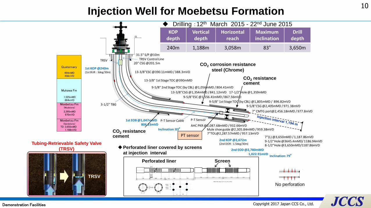
Inclination: 83°
Quaternary
Mukawa Fm
464mMD
1,525mMD
2,415mMD
TD 3,650mMD1,188mVD
Moebetsu Fm
Nina Fm
3,443mMD / 1,153mVD
9-5/8"CSG @2,405mMD / 971.38mVD
2nd KOP @2,672m(2nd DOR : 1.5deg/30m)
2nd EOD @2,780mMD 1,022.91mVD
Inclination: 79°
Moebetsu Fm(mudstone)
(sandstone)
KOPdepth
Verticaldepth
Horizontalreach
Maximuminclination
Drilldepth
240m 1,188m 3,058m 83° 3,650m
Injection Well for Moebetsu Formation
Perforated liner covered by screens
at injection interval
Perforated liner Screen
PT sensorCO2 resistance cement
CO2 corrosion resistance
steel (Chrome)
Drilling :12th March 2015 - 22nd June 2015
CO2 resistance cement
Tubing-Retrievable Safety Valve
(TRSV)
TRSVVD(m
)
0
GL
100
200
300
400
500
600
700
800
900
1000
1100
1200
1300
1400
1500
1600
1700
1800
1900
2000
2100
2200
2300
2400
2500
2600
2700
2800
2900
3000
3100
3200
26"H
ole @
202.0m
DD
Qua
tern
ary
458m
DD
Muk
awa
873m
DD
(873
mVD)
Moe
bets
uM
oebe
tsu
chan
nel s
and:
1076
m~
1226
mDD
(107
1m~
1208
mVD
)12
30m
DD
(121
1mVD
)
Nin
a16
38m
DD
(152
4mVD
)
Bira
tori/
Kar
umai
2289
mDD
(200
6mVD
)
Fure
oi
2826
mDD
(240
4mVD
)
Takino
ue(T
1)
3700
mDD
(304
6mVD
)
KO
P@
870m
DD
EOB@
1320
mDD
1286
mVD
20"C
SG S
hoe
@20
0.0m
DD
13-3
/8" ES
C@
410m
DD
13-3
/8"C
SG S
hoe @
1408
mDD
1353
mVD
9-5/
8"CSG S
hoe @
2747
mDD
2346
mVD
7"Li
ner C
SG @
3700
mDD
3047
mVD
7"TO
L @
2639
mDD
2265
mVD
13-3
/8" TO
C@
825m
DD
(by
CBL)
8
25m
VD
9-5/
8" E
SC@
1519
mDD
1436
mVD
9-5/
8" T
OC@
873m
DD
(by
RCBL)
8
73m
VD
17-1
/2"H
ole@
1412
mDD
1356
mVD
12-1
/4"H
ole@
2753
mDD
2350
mVD
8-1/
2"Hol
e@37
00m
DD
3047
mVD
No.
2 In
ject
ion Tes
t 290
7m-3
289m
DD
2462
-274
4mVD
No.
1 In
ject
ion Tes
t 338
2m-3
698m
DD
2813
m-3
045m
VD
No.
3&No.
3a In
ject
ion Tes
t 107
7m-1
217m
DD
1072
-120
0mVD
1.48
SG N
aBrブ
ライ
ン
ワイ
ヤー
ライ
ンケ
ーブ
ルSei
smic
sen
sor
PT s
enso
r
Lubr
icat
or V
alve
Con
trol
Lin
e
4-1/
2"TBG 1
2.60
# NU 5
00m
No perforation
Quaternary
Moebetsu Fm(Mudstone)
Mukawa Fm
464mMD458mVD
1,525mMD864mVD
2,395mMD970mVD
Moebetsu Fm(Sandstone)
TD 3,650mMD1,188mVD
Demonstration Facilities

11
Copyright 2017 Japan CCS Co., Ltd.
The amount of injected CO2 estimated 600,000 tonnes in total.
CO2 Flow Simulation for Moebetsu Formation
i=51
CCS1IW2
<An example of CO2 saturation and molality maps>
Completion of
Injection
After 200 years
i=51
CCS1IW2
i=51
CCS1IW2Well head location
Well head locationGas Saturation
i=51
CCS1IW2
i=51
CCS1IW2
Well head location
Well head location
i=51
CCS1IW2
Molality(CO2)
Demonstration Facilities

12
Copyright 2017 Japan CCS Co., Ltd.
Items Observed objects Observation
frequencyRemarks
Injection well Downhole : Temperature and pressure
Wellhead : Pressure, Injection rate of
CO2
Continuous • Injection well for Takinoue Formation
• Injection well for Moebetsu Formation
Observation well Downhole : Temperature and pressure,
micro-seismicity and natural
earthquakes
Continuous• Observation well OB-1 for Takinoue Formation
converted from an survey well CCS-1
• Observation well OB-2 for Moebetsu Formation
• Observation well OB-3 for Takinoue Formation
OBC : Ocean Bottom
Cable
Micro-seismicity and natural
earthquakes
Signal of 2D seismic survey
Continuous • OBC line passes directly above the injection points of
reservoirs.
OBS : Ocean Bottom
Seismometer
Micro-seismicity and natural
earthquakes Continuous • One wired OBS above the injection points
• Three stand-alone OBSs at the surrounding area of
injection points of reservoirs
Onshore
seismometer
Micro-seismicity and natural
earthquakes Continuous • West region of Tamakomai city
2D seismic survey Distribution of CO2 Periodic • Utilizing OBC as seismic sensors
3D seismic survey Distribution of CO2 Periodic • A baseline survey was completed during the
investigation period.
Marine
environmental
monitoring
Chemical, physical and biological
dataPeriodic • Monitoring plan is to be drawn up after the baseline
survey and marine environmental impact assessment.
Monitoring Items
Monitoring and Public Outreach
13
Copyright 2017 Japan CCS Co., Ltd.
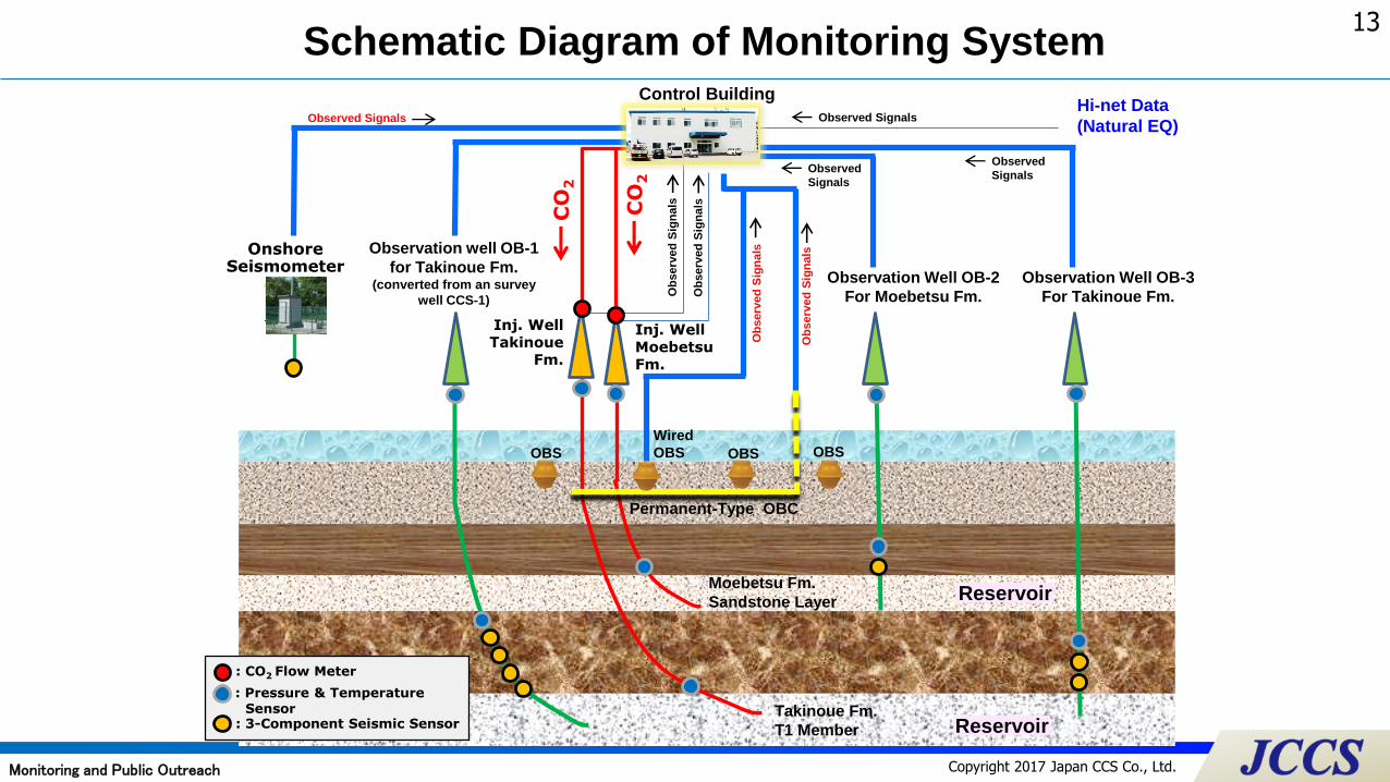
Control Building
Moebetsu Fm.
Sandstone Layer
Takinoue Fm.
T1 Member
OBSWired
OBS
Permanent-Type OBC
OBSOBS
Schematic Diagram of Monitoring System
Observation Well OB-2
For Moebetsu Fm.
Observation Well OB-3
For Takinoue Fm.
Hi-net Data
(Natural EQ)
Observed
Signals Observed
Signals
Observed Signals
OnshoreSeismometer
Observation well OB-1
for Takinoue Fm.(converted from an survey
well CCS-1)
CO
2
CO
2
Inj. WellMoebetsuFm.
Inj. WellTakinoue
Fm.
Ob
serv
ed
Sig
na
ls
: Pressure & Temperature Sensor
: 3-Component Seismic Sensor
: CO2 Flow Meter
Ob
serv
ed
Sig
na
ls
Ob
serv
ed
Sig
na
ls
Observed Signals
Ob
serv
ed
Sig
na
ls
Monitoring and Public Outreach
Reservoir
Reservoir
14
Copyright 2017 Japan CCS Co., Ltd.
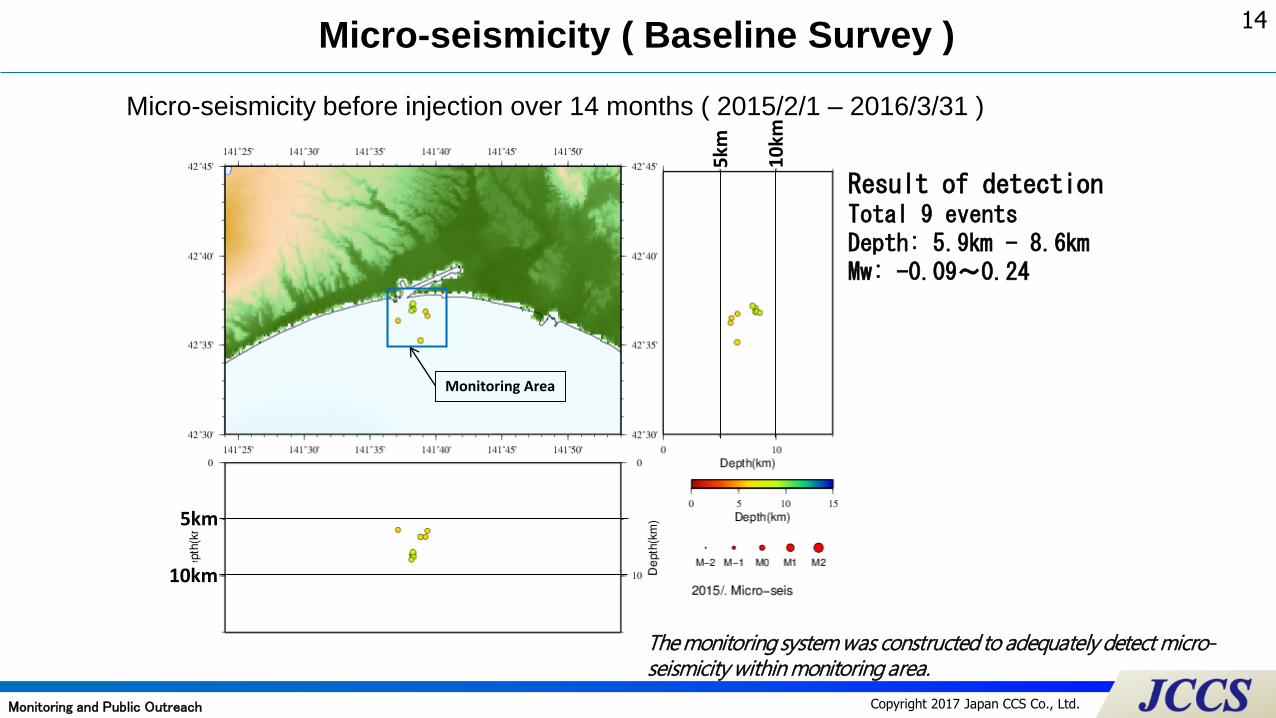
Micro-seismicity ( Baseline Survey )
Monitoring Area
Result of detectionTotal 9 eventsDepth: 5.9㎞ - 8.6㎞Mw: -0.09~0.24
Micro-seismicity before injection over 14 months ( 2015/2/1 – 2016/3/31 )
10km
10
km
5km
5km
The monitoring system was constructed to adequately detect micro-seismicity within monitoring area.
Monitoring and Public Outreach

15
Copyright 2017 Japan CCS Co., Ltd.
An example of Natural Earthquake after start of CO2 injection
X
Y
Z
Observation record of Onshore Seismometer
Pre
ssure
(M
pa)
Tem
pera
ture
(deg
.C)
Injection well for Moebetsu Fm. Average Pressure: 9.56MPa (at 930m in depth)
Injection well for Moebetsu Fm. Average Temperature: 38.0℃ (at 930m in depth)
Distance of
approx.90km
This earthquake had no influence on temperature and pressure of the cap rock strata.
Monitoring Area
Borehole Pressure
Borehole Temperature
TomakomaiThree components
30sec.
Earthquake Information Announced by the Japan Meteorological Agency
Time & date 14:21:28(JST) 16 June, 2016
Epicenter Lat. 41°56.9′N
Lon. 140°59.2′E
Depth 11 km
Magnitude 5.3
Seismic Intensity
at near epicenter
and Tomakomai
Lower 6 and 2 on Japanese seismic scale.
Approx. Ⅷ and approx. Ⅱ-Ⅲ on Mercalli
intensity scale.
Epicenter

16
Copyright 2017 Japan CCS Co., Ltd.
Plotted on Japan Coast Guard nautical chart
Takinoue ObsWell
MoebetsuObsWell
OB-2 (vertical)
CO2 Capture & Injection Plant
MoebetsuCO2 Plume
Takinoue CO2 Plume
Marine environment shall be surveyed based on “Act on Prevention of Marine Pollution and Maritime Disaster” by which geological storage of CO2 under the seabed is regulated.
1 . Survey Area
• 12 survey points in Tomakomai Port Area
3. Surveys in Three Stages
2. Methods of Survey
• Seabed survey by Side-Scan Sonar and Sub-bottom Profiler
• Current direction and speed survey by Current Meter
• Sampling of seawater by Water Sampler for concentration of salt etc. and plankton observation
• Seabed mud survey by Bottom Sampler
• Collection of benthos by Net or Dredge Unit
• Observation of benthos by divers or ROV
• During EPC period
• During demonstration operation
⁻ During CO2 injection
⁻ After CO2 injection
• After demonstration operation
Side-Scan Sonar
Bottom Sampler
Water Sampler
Dredge Unit
ROV
St. : Survey Point
Environmental Survey Points
Marine Environmental Survey
Monitoring and Public Outreach

17
Copyright 2017 Japan CCS Co., Ltd.
Public Outreach Activities in 2016
① Panel Exhibitions: total of 5 times in Sapporo, Tomakomai and neighboring towns
② Site Visits: total number of visitors: 2,013 (154 groups) from universities, research associations, local
government, etc.
③ Environmental Exhibitions: “Eco-Pro 2016”, “2016 Global Warming Prevention Exhibition” in Tokyo
④ Kids Science Rooms and others: games and experiments to learn about global warming, CO2, CCS
(total of 2 times in Tomakomai)
⑤ CCS Forum: March 4, 2017 in Tomakomai (attendance: 312)
① Panel Exhibitions ② Site Visits ③ Env. Exhibitions ⑤ CCS Forum
Monitoring and Public Outreach
④ Kids Science Rooms
18
Copyright 2017 Japan CCS Co., Ltd.
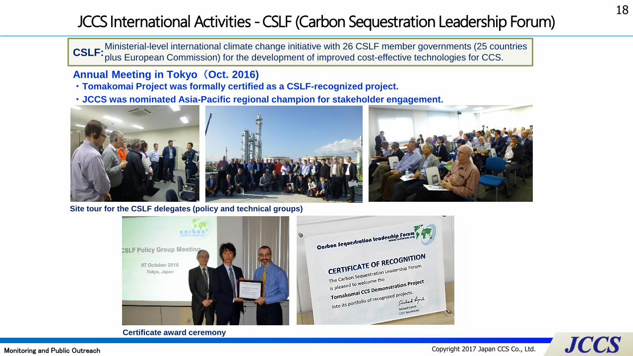
JCCS International Activities -CSLF (Carbon Sequestration Leadership Forum)
CSLF:
Annual Meeting in Tokyo(Oct. 2016)・Tomakomai Project was formally certified as a CSLF-recognized project.
・JCCS was nominated Asia-Pacific regional champion for stakeholder engagement.
Ministerial-level international climate change initiative with 26 CSLF member governments (25 countries
plus European Commission) for the development of improved cost-effective technologies for CCS.
Site tour for the CSLF delegates (policy and technical groups)
Certificate award ceremony
Monitoring and Public Outreach

19
Copyright 2017 Japan CCS Co., Ltd.
Conclusion
Full cycle CCS system from capture to storage is in operation; objective is to develop practical CCS
technology by around 2020
Demonstrate safety and reliability of CCS system
Remove concerns about earthquakes
Unique features of project
Efficient two-stage capture system
Deviated injection wells from onshore site into offshore reservoirs
Extensive monitoring system
Test and current injection results indicate superior injectivity of shallow reservoir
Extensive stakeholder engagement being undertaken
Maintaining close communications with Tomakomai fishery cooperative, local government
20
Copyright 2017 Japan CCS Co., Ltd.
(写真挿入)Thank you for your attention.
http://www.japanccs.com
Please visit Japex booth #9030 ;
・ Japex Booth to Introduce Tomakomai CCS Project