Tom McDermott, N5EG March 4, 2009
14
Antenna Modeling in Software Tom McDermott, N5EG March 4, 2009
Transcript of Tom McDermott, N5EG March 4, 2009

Antenna Modeling in SoftwareTom McDermott, N5EGMarch 4, 2009

Why Model an Antenna?
� It’s very difficult to assemble, adjust, modify, and optimize a physical antenna.
� It’s very difficult or time consuming to measure the gain, pattern, and efficiency of a real antenna.
� Antenna models can tell us about efficiency, pattern, gain, and input impedance.
� It’s FAST. We can iterate through a lot of models and quickly focus on those that are most useful.
� Properly done, it’s quite accurate.
� Improperly done, it can generate complete nonsense.

Where does it come from?
� Original software was called BRACT, superseded by Antenna Modeling Program (AMP), developed 1971.
� Numerical Electromagnetics Code (NEC-2) developed at Lawrence Livermore Lab –1981.� Sponsored by Naval Ocean Systems Center.
� FORTRAN source code is in the public domain.
� NEC-4 also developed at LLL.� Not in the public domain. Requires a license from LLL. $250.

How does it work?
� Wire antennas are modeled using Electric-Field Integral Equation (EFIE).
� Antenna is broken up into small pieces called segments.
� Each segment has current in it
� Due to sources feeding power to the antenna, plus
� Currents induced by an impinging field from neighboring segments (and possibly external sources).
� Current in each segment causes radiation.
� The antenna pattern is the sum of all the fields contributed by each segment of the antenna.

CoordinatesRectangular (data entry) and Polar (pattern plots)
� Z = up/down X = left/right Y = front/back
� Theta θ = elevation, Phi φ = azimuth
21 segments (one is a source)

Ground
� Ground affects the antenna in 3 ways:1. Modifying the currents in the segments due to near-field
interaction,2. Changing the field illuminating the antenna,3. Changing the reradiated field.
� Perfect ground is a perfectly-conducting sheet at Z=0 extending to infinity in all directions (don’t we wish).
� The NEC-2 real ground (Norton-Sommerfeld), a lossysheet of zero-thickness at Z=0 extending to infinity in all directions.
� Accurate down to about 0.001 wavelengths above ground. The antenna is not allowed to touch the ground sheet.
� NEC-4 can model ground with actual depth below ground.
� Computationally, ground is handled by projecting an image antenna below ground. Quicker to compute, reasonably good accuracy.
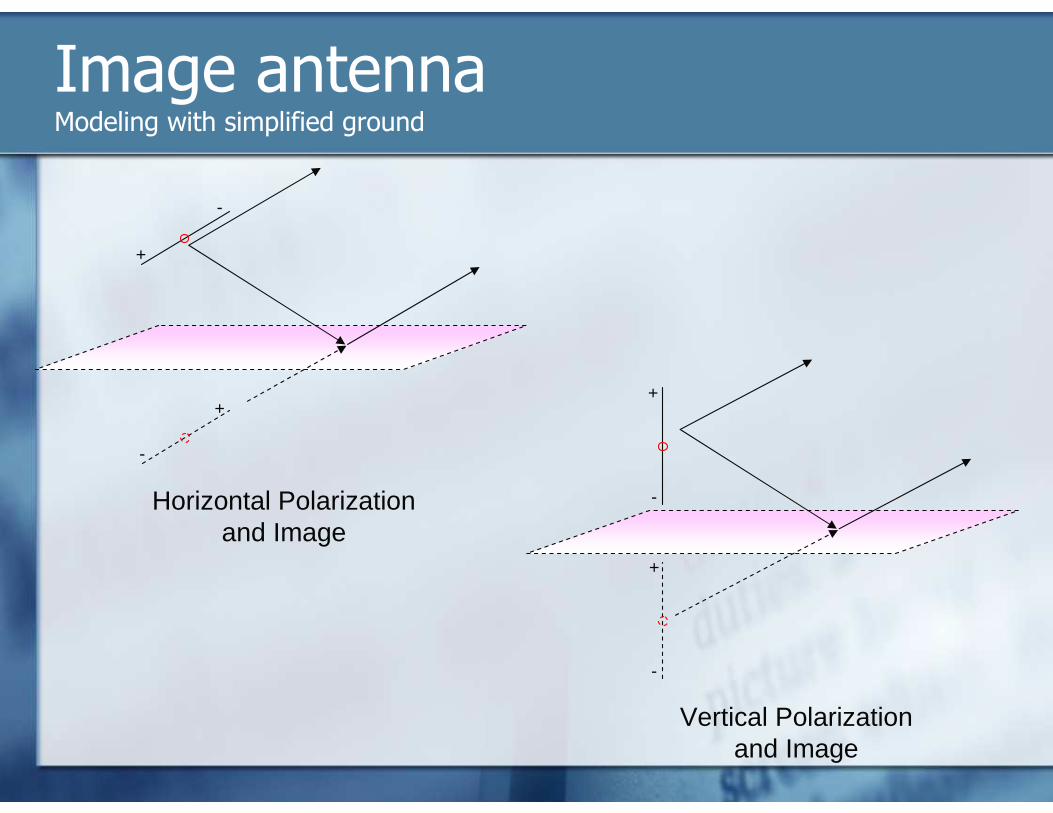
Image antennaModeling with simplified ground
+
-
+
-
+
-
+
-Horizontal Polarizationand Image
Vertical Polarizationand Image

Software
� NEC-2 is free. It’s difficult to use.
� Interface software provides a user-friendly interface to NEC-2.� Capture / Edit the antenna geometry, loads, and sources.
� Display the antenna pattern, input impedance, antenna efficiency. Frequency sweeps.
� Allow selecting loads, sources, wire size, etc.
� Optimization.
� Most newer interface programs also work with NEC-4.
Software
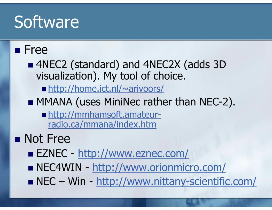
� Free� 4NEC2 (standard) and 4NEC2X (adds 3D visualization). My tool of choice.� http://home.ict.nl/~arivoors/
� MMANA (uses MiniNec rather than NEC-2).� http://mmhamsoft.amateur-radio.ca/mmana/index.htm
� Not Free� EZNEC - http://www.eznec.com/
� NEC4WIN - http://www.orionmicro.com/
� NEC – Win - http://www.nittany-scientific.com/

PatternPolar Coordinates
� Azimuth & Elevation or 3D

Frequency SweepVarious ways to show Zin
� Zin, SWR, return loss vs. Frequency

Frequency SweepSmith Chart display of Zin

Efficiency & Matching
� Efficiency is the antenna itself.
� Radiat-eff includes ground losses.

Comparing Antennas40m dipole at 49 feet vs. 43 foot vertical+32 radialsReal Ground “good”
Broadside to Dipole End of Dipole
At 45-degrees elevation
At 25-degrees elevation(best angle for vertical)


![McDermott Wound Care[1]](https://static.fdocuments.net/doc/165x107/54384d3cafaf9fb92e8b4995/mcdermott-wound-care1.jpg)