Toll Free: Die Head / Tangential Chaser Management B...
13
EST thread finish and tool life depends upon proper management of the chasers, die head, and the machine upon which the tool is mounted. This information gives corrective measures for the morecommon troubles which affect finish and tool life. Operating problems are defined and corrective measures given strictly on the basis of what can be done to improve threading results. It does not deal with considerations out- side those parameters. For example, a given material may be acceptable in all respects except thread finish. In such instances, it will be up to the user to decide whether to accept the finish, or to change to a more expensive, better threading material. A particular problem can be the source of more than one trouble. Therefore, such problems may, for the sake of quick reference, be covered in more than one section. Complete and detailed information on how to grind and use chasers, care and operation of die heads can be found in the 17th and earlier editions of the Landis Threading and Forming / Thread Data Handbook. This publication also includes useful information on collapsible taps, thread rolling and eighty-four pages of helix angle and thread data charts on all the major thread forms. Maximizing Chaser And Threading Performance To maximize tool life and threading performance, some trial and error adjustments must be made as the threading operation progresses. However, preparations for good results should begin before the spindle makes a revolution. Die Head / Tangential Chaser Management B Where it is possible to do so, select materials that will give good threading results. Metallurgical quality should be consistent with that established for a given material. The best possible coolant, correct speed, and other constants should be chosen so that those factors are eliminated as possible trouble sources. Lead Error Of a progressive nature, lead error is measured in terms of plus or minus per pitch, accumulated over a given thread length. Because of a number of contributing factors, it can be difficult to trace and correct. Aside from possible sources of trouble, lead should first be looked at in terms of tolerance demanded and the type of threading means required to produce it. If tolerances are to be held to .002" per inch or better, a machine with leadscrew or other type of positive feed means will be required. With equipment in good condition, lead error can be held to .0005" per inch with precision positive feed. While possible to use for coarse pitch, lesser tolerance threads, hydraulic, air, or spring feeds are not recommended for close tolerance work. Landis-Solutions.com Landis Solutions LLC 360 South Church Street Waynesboro, PA 17268-2610 Toll Free: USA: +1.800.358.3500 Fax: +1.888.718.2922 Canada: +1.888.828.6340 e-mail: [email protected]
Transcript of Toll Free: Die Head / Tangential Chaser Management B...

EST thread finish and tool life depends
upon proper management of the
chasers, die head, and the machine upon
which the tool is mounted.
This information gives corrective
measures for the morecommon troubles which affect
finish and tool life.
Operating problems are defined and corrective measures
given strictly on the basis of what can be done to improve
threading results. It does not deal with considerations out-
side those parameters. For example, a given material may
be acceptable in all respects except thread finish. In such
instances, it will be up to the user to decide whether to
accept the finish, or to change to a more expensive,
better threading material.
A particular problem can be the source of more than one
trouble. Therefore, such problems may, for the sake of
quick reference, be covered in more than one section.
Complete and detailed information on how to grind and
use chasers, care and operation of die heads can be
found in the 17th and earlier editions of the Landis
Threading and Forming / Thread Data Handbook. This
publication also includes useful information on collapsible
taps, thread rolling and eighty-four pages of helix angle
and thread data charts on all the major thread forms.
Maximizing Chaser And ThreadingPerformance
To maximize tool life and threading performance,
some trial and error adjustments must be made as the
threading operation progresses. However, preparations
for good results should begin before the spindle makes
a revolution.
Die Head / Tangential Chaser Management
BWhere it is possible to do so, select materials that will
give good threading results.
Metallurgical quality should be consistent with that
established for a given material.
The best possible coolant, correct speed, and other
constants should be chosen so that those factors are
eliminated as possible trouble sources.
Lead ErrorOf a progressive nature, lead error is measured in terms of
plus or minus per pitch, accumulated over a given thread
length. Because of a number of contributing factors, it can
be difficult to trace and correct.
Aside from possible sources of trouble, lead should first be
looked at in terms of tolerance demanded and the type of
threading means required to produce it.
If tolerances are to be held to .002" per inch or better,
a machine with leadscrew or other type of positive
feed means will be required. With equipment in good
condition, lead error can be held to .0005" per inch with
precision positive feed.
While possible to use for coarse pitch, lesser tolerance
threads, hydraulic, air, or spring feeds are not
recommended for close tolerance work.
Landis-Solutions.com
Landis Solutions LLC 360 South Church Street Waynesboro, PA 17268-2610
Toll Free: USA: +1.800.358.3500 Fax: +1.888.718.2922 Canada: +1.888.828.6340
e-mail: [email protected]

Die Head / Tangential Chaser Management
Lead Variation Corrective Measures
Regular chaser holder sets are fur-
nished to produce a range of threads
of a given series - UNC, UNF, etc.
Each holder set has a mean helix
angle which allows it to produce all
the standard diameter and pitch
combinations within that range -
within tolerances for that series.
Special chaser holders having an
exact helix angle for a specific
diameter and pitch combination are
available. Where lead tolerance is
very close and cannot be realized
with regular holders, special holders
should be employed.
For non-leadscrew threading with a Landmatic pull-off type
head, or when using a Landex yoke operated type head,
chasers require a “lip rake” grind. With this grind the rear
threads extend over center to produce a nut-action with
the finished thread. This nut engagement is used to pull
Landmatic type die heads open.
For leadscrew threading with Lanco
yoke operated heads, chasers are
ground with a straight rake and lead
combination grind. The object of this
grind is to place the cutting edge
exactly on the work centerline so no
nut-action is generated that would
tend to override the leadscrew feed.
This same general type of grind is
used to “jam-cut” taper pipe threads
like NPT.
With either a lip-rake or straight rake grind, an incorrect
grind angle or deviations from the chaser setting position
will tend to produce lead error.
For straight threading, chasers are given back clearance to
assure that they cut only with the throat and first or second
full thread. The first full thread is included on 20 pitch, 1
mm pitch and coarser, the second full thread on 22 pitch,
1.25 mm pitch and finer. The remaining threads extend
overcenter and provide nut-action without interfering with
the lead being produced.
Any condition that reduces the back clearance between the
chaser and finished thread will increase lead. Conversely, an
increase in clearance will decrease lead.
Landis-Solutions.com
Landis Solutions LLC 360 South Church Street Waynesboro, PA 17268-2610
Toll Free: USA: +1.800.358.3500 Fax: +1.888.718.2922 Canada: +1.888.828.6340
e-mail: [email protected]

C. Dull Chasers / Incorrect Starting Pressure
Maintain a sharp cutting
edge. Dull chasers
increase the resulting
pressure which causes
bell-mouthing thus
reducing clearance.
Incorrect starting
pressure, especially
when the work is being
manually fed, can affect
lead. Generally of a temporary nature, this problem will
disappear as the operator gains experience.
Side Shaved Threads
Improper starting pressure, or any condition which affects
proper tracking of the chasers will cause side shaving. Side
shaved threads can give an appearance of taper.
Normally found on beginning threads, eventual full
engagement of the chasers will correct the condition.
This condition can be confirmed
visually. Side shaved threads
have a wider root than normal.
When hand feeding, new
operators need to learn to
apply correct starting pressure.
When mechanical feed is
being employed, the condition
causing the problem must be
identified and corrected.
Die Head / Tangential Chaser Management
Conditions That Affect Clearance and Lead
A. Improper Chaser Setting
Damaged seating surfaces or dirt can
cause improper chaser positioning.
Seating surfaces should be cleaned
and checked before chasers are
installed. Chasers should be cleaned
and holder seating surfaces free of
dirt. Damaged holder seating sur-
faces should be honed.
B. Threading Heat Treated Material
Harder materials create increased cut-
ting pressures that force holders to
bell-mouth outward which effectively
reduces clearance. Several alterna-
tives are possible. Use chasers with
longer throats for reduced chip size
which spreads the cut over a longer
length. Also, make sure the trunnion
clearance is correct for the die head
being used. Excessive trunnion play allows an even greater
degree of bell-mouth, especially when using wider chasers.
If this condition is suspected, place shim stock (starting
with .003") between the chasers and each clamp as shown
by the illustration. If this helps or corrects the problem, the
condition is present. Vary the amount of shim until the best
results are obtained. It is possible to have future chasers
made with extra clearance to offset the degree of bell-
mouth.
Chasers are stepped off for proper tracking. With four
chaser heads, the tools are mounted 90º apart, which
results in each chaser being stepped off 1/4 lead from
other chasers in the set. On a six chaser head, the step is
1/6 lead. The step-off allows the chasers to follow each
other in the cut. Any condition that interferes with tracking
will produce side shaving for the full length of the thread.
Conditions that affect tracking
A. Improper Trunnion Clearance
A prescribed amount of trunnion clearance or “play” must
be maintained between the chaser holders and the face of
“Heat Treated” style die heads. Trunnion play serves two
purposes. First, it allows head components to move without
binding during opening and closing. Secondly, it allows
chasers to properly track each other in the cut. Uniform and
correct play must be used for all holders or the chasers will
not properly track. As shown by the chart, the prescribed
amount of clearance varies with size and style of head.
B. Dirt or Chips
Chips and dirt packed between the holders and die head
face will eliminate or reduce play and affect tracking.
Holders should be periodically removed and cleaned.
C. Worn Equipment
Heads with excessive wear should be rebuilt or replaced.
The die head and machine and the die head and workpiece
must be in acceptable angular and concentric alignment.
Landis-Solutions.com
Landis Solutions LLC 360 South Church Street Waynesboro, PA 17268-2610
Toll Free: USA: +1.800.358.3500 Fax: +1.888.718.2922 Canada: +1.888.828.6340
e-mail: [email protected]

Die Head / Tangential Chaser Management
Rough Threads
A common cause of rough threads is
improper chaser setting. Chasers
work best usually when set slightly
back of center where they have
natural cutting clearance.
Minor deviations from initial gage
setting position are made to
accommodate the particular machineability of a specific
material. This becomes a matter of trial and error.
However, if chasers are set too far forward, the thread tops
will be torn, the chasers will over-heat, and prematurely
wear. If set too far back, threads will be chattered and out-
of-round. The latter condition can be detected by rotating
the thread between thumb and forefinger.
Chips welding to the tool cutting edge can be the cause.
Welding occurs when threading gummy materials that do
not cut well, or in response to any condition causing
excessive heat.
When threading gummy materials, try using a high rake for
better shearing action. Start with the recommended angle
and increase by degrees until best results are obtained.
Finish will never be as good as when threading a harder
material that gives better shearing action. The corrective
measure used, therefore, improves but doesn’t completely
cure the condition.
Use the best grade of cutting oil liberally flooding the cut-
ting area. See the section on “Coolant” for more informa-
tion on this subject.
Grind the cutting end grinds as smooth as possible. A
rough finish will not cut as free as a smooth one. Any
condition which interferes with cutting efficiency builds
heat and heat hinders results.
Use the longest throat possible to spread the chip over the
longest length possible. On tougher materials or coarser
threads such as Acme, Modified Square, use Roughing and
Finishing Form, or Roughing Form Throat chasers. With
these, the thread profile of the throat, or the throat and first
or second full thread are reduced in thickness. Each modi-
fied tooth progressively removes a few thousandths until a
full tooth finishes the thread. See the publication on Landis
Tangential Chasers for more detailed information on these
special features.
Make sure that the chasers are mounted in proper rotation
and that all have the same throat angle.
Use the proper speed for the material, diameter and pitch
to be threaded.
An improper rake or lip-rake of too little “hook” can be the
cause.
The accompanying chart list recommended “starting”
rakes. Deviate from the “starting” angle until best results
are realized. New “boxed” chasers are ground with a 22º
rake suitable for mild steel. If chasers are to be used for
other materials, so state on the order and they will factory
ground accordingly.
The machineability of some materials is so poor that it will
be difficult to obtain good finish regardless of what rake
angle or tricks of the trade used.
Lip-rake grinds should be “hooked,” as the material may
require and on special thread forms like Acme, so the
lipped section falls on the centerline, or rough threads can
result. To obtain this position, the lip-rake should be
hooked back an amount equal to the chaser holder helix
angle.
Make certain that the die head, workpiece, and machine
are in angular and concentric alignment. Check and
indicate to rule out misalignment as a trouble source.
The die head should not over extend from the mounting.
Landis-Solutions.com
Landis Solutions LLC 360 South Church Street Waynesboro, PA 17268-2610
Toll Free: USA: +1.800.358.3500 Fax: +1.888.718.2922 Canada: +1.888.828.6340
e-mail: [email protected]

Out-Of-Roundness / Chatter
Out-of-roundness is easily detected and can
be readily felt by rotating the thread
between thumb and forefinger. Chatter is
readily visible on the thread. Both conditions
have common causes. Chasers set too far back
of center can cause either. This is easily correct-
ed, by advancing each chaser equally, in small
increments, until the condition disappears.
Verify that the thread and other diameters of
the workpiece are concentric.
The workpiece and die head must be rigid.
Lack of workpiece rigidity will tend to be more
apparent when coarser pitches and/or long
thread lengths are involved. Use of Centering
Throat chasers often solves this problem. These
chasers employ a pad which precedes the throat to estab-
lish a bearing on the workpiece O.D. to steady the part.
The O.D. must be held consistently uniform to allow this
type chaser to be used.
Never use chipped chasers. Keep the cutting edge sharp.
If damaged beyond regrinding, replace.
Chasers in the set must all have the same throat angle, for
example, and cannot be mixed.
The die head and machine must be in concentric and
angular alignment. Indicate the die head and machine
components for both conditions to rule out either as a
source of trouble.
Use the correct rake or lip rake. Not only must the correct
angle be used, but the angle must be uniformly applied to
all chasers of the set.
Die Head / Tangential Chaser Management
Out-of-roundness occurs on the starting threads of sheared
stock. While virtually impossible to completely eliminate
the condition, the use of the correct throat can minimize
the result.
Use chasers having the throat starting sufficiently below the
root of the thread will allow the bell-mouth of the chasers
to remove the excess metal.
Tapered Threads
Defined as a progressive increase or decrease of major
pitch or root diameters over the thread length. Taper is
difficult to trace since it is not readily visible.
Small to Large Taper
Stepped flanks from improper starting on pressure can
appear to be taper. When checked over wires, the step
allows deeper seating of the wires which is falsely
interpreted as taper. The condition usually results from
improper hand feed. Checking the
thread with a comparator will clarify
the condition.
Conditions that cause chaser bell-
mouthing will reduce chaser clearance
and result in taper. This tends to occur
more when a straight rake grind is
used.
Clearance placed in a chaser at manufacture is based on
the material and its specification.
Harder and gummy materials which are more difficult to
shear, and abrasive materials which dull or dub the chasers
causing the cutting edge to dig in, result in higher cutting
pressures with reduced clearance.
Greater back clearance is, or can be, placed in chasers
used for such applications.
Worn or defective head parts, such as locking and closing
pins and their respective bushings, are a common cause of
taper. They wear tapered and the taper produced on the
part will be at the end of the thread where the head opens.
The prepared blank must be straight. If the blank is not
straight, the thread O.D. will be tapered, but the P.D. and
root diameters will be straight.
Large to Small Taper
This condition is usually the result of chasers which are set
too far back of center. Advance the chasers equally, in
small amounts, until the condition is corrected.
Landis-Solutions.com
Landis Solutions LLC 360 South Church Street Waynesboro, PA 17268-2610
Toll Free: USA: +1.800.358.3500 Fax: +1.888.718.2922 Canada: +1.888.828.6340
e-mail: [email protected]

Die Head / Tangential Chaser Management
Drunken Threads
This is a “wavy” condition of the thread going plus or
minus off true helical lead when measured over the circum-
ference of one thread revolution.
One possible cause is misalignment. Check die head and
machine for alignment.
Use of a low lead angle with hand feed can
result in drunken threads. For UN,
Whitworth, BSF and ISO coarse, and
straight pipe threads, the angle should be
90º for 11 pitch and coarser, 92º for 12
pitch and finer.
To establish the lead angle where special
chaser holders are used, subtract the helix
angle from 90º, then add 3º.
If the holder has a helix angle of 6º, for example, the lead
angle would be 90º - 6º + 3º or 87º. For convenience, helix
angles of special holders are stamped in the sliding block
slot, or on the holder face.
Chipped chasers, chasers set too far back of center,
improper feed and worn head parts can cause a drunken
thread condition.
Drunken threads are common when cutting over
interrupted cuts or when threading hexagon, square,
or other unround forms.
Chipped Chasers
There are numerous causes of chipped chasers.
The chasers striking the shoulder before the die head
opens and is retracted. An allowance must be added to the
throat length to allow for the head’s forward movement,
which occurs during opening motion at the end of the
thread. The allowance is based on thread pitch. Refer to
the charts for the appropriate dimensions.
Do not water quench chasers when grinding. Rapidly
cooling a hot chaser creates cracks which cause teeth to
chip during use.
Higher rake angles weaken the cutting edge. Using a rake
lower than recommended generates high cutting pressures
with possible chipping.
Rapidly force-starting the head onto the work.
Work not gripped tight enough, especially when positive
feed is being used.
Landis-Solutions.com
Landis Solutions LLC 360 South Church Street Waynesboro, PA 17268-2610
Toll Free: USA: +1.800.358.3500 Fax: +1.888.718.2922 Canada: +1.888.828.6340
e-mail: [email protected]
Die Head / Tangential Chaser Management
Chip Welding
When good threads are followed by a number of bad
threads, followed by more good threads, it is unlikely that
a mechanical problem is the cause.
Welding of the cutting edge should be one of the first
possibilities investigated.
Chasers will start off cutting satisfactory. As the weld builds
in size, thread quality becomes worse. The weld will
continue to build until it snaps off, then good threads will
return.
Welding is caused by excessive heat so the reason for the
heat must be located and corrected.
Before spending time chasing possible causes, stop and
recollect. Has anything changed? Is the material the same,
is a different person doing the end grinding, are chasers
with different throats being used?
Some steels weld easier than others and a material change
might be required to obtain the desired results.
Use the best grade of threading coolant and flood the
cutting operation. When cutting Acme and forms requiring
heavy metal removal, such as Acme, use the longest throat
possible. Use the highest rake possible for best shearing
action and grind the cutting end as smooth as
possible for cleaner cutting with less friction.
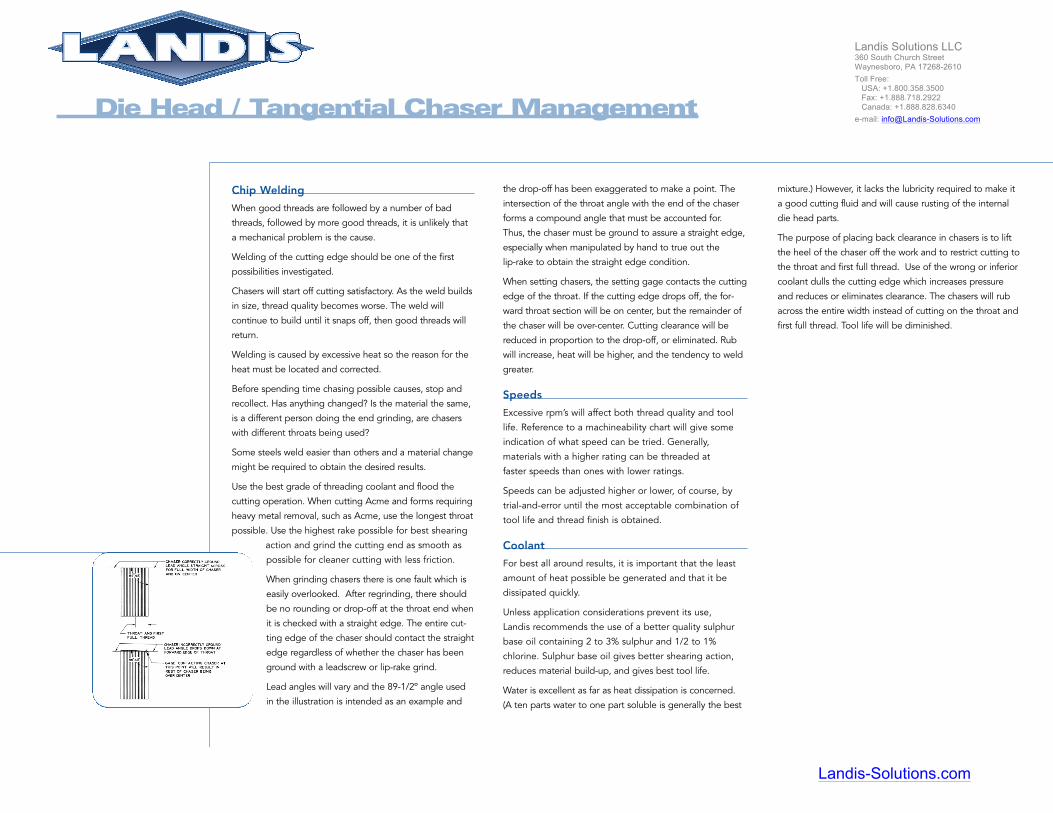
When grinding chasers there is one fault which is
easily overlooked. After regrinding, there should
be no rounding or drop-off at the throat end when
it is checked with a straight edge. The entire cut-
ting edge of the chaser should contact the straight
edge regardless of whether the chaser has been
ground with a leadscrew or lip-rake grind.
Lead angles will vary and the 89-1/2º angle used
in the illustration is intended as an example and
the drop-off has been exaggerated to make a point. The
intersection of the throat angle with the end of the chaser
forms a compound angle that must be accounted for.
Thus, the chaser must be ground to assure a straight edge,
especially when manipulated by hand to true out the
lip-rake to obtain the straight edge condition.
When setting chasers, the setting gage contacts the cutting
edge of the throat. If the cutting edge drops off, the for-
ward throat section will be on center, but the remainder of
the chaser will be over-center. Cutting clearance will be
reduced in proportion to the drop-off, or eliminated. Rub
will increase, heat will be higher, and the tendency to weld
greater.
Speeds
Excessive rpm’s will affect both thread quality and tool
life. Reference to a machineability chart will give some
indication of what speed can be tried. Generally,
materials with a higher rating can be threaded at
faster speeds than ones with lower ratings.
Speeds can be adjusted higher or lower, of course, by
trial-and-error until the most acceptable combination of
tool life and thread finish is obtained.
Coolant
For best all around results, it is important that the least
amount of heat possible be generated and that it be
dissipated quickly.
Unless application considerations prevent its use,
Landis recommends the use of a better quality sulphur
base oil containing 2 to 3% sulphur and 1/2 to 1%
chlorine. Sulphur base oil gives better shearing action,
reduces material build-up, and gives best tool life.
Water is excellent as far as heat dissipation is concerned.
(A ten parts water to one part soluble is generally the best
mixture.) However, it lacks the lubricity required to make it
a good cutting fluid and will cause rusting of the internal
die head parts.
The purpose of placing back clearance in chasers is to lift
the heel of the chaser off the work and to restrict cutting to
the throat and first full thread. Use of the wrong or inferior
coolant dulls the cutting edge which increases pressure
and reduces or eliminates clearance. The chasers will rub
across the entire width instead of cutting on the throat and
first full thread. Tool life will be diminished.
Landis-Solutions.com
Landis Solutions LLC 360 South Church Street Waynesboro, PA 17268-2610
Toll Free: USA: +1.800.358.3500 Fax: +1.888.718.2922 Canada: +1.888.828.6340
e-mail: [email protected]

When coarse pitch thread forms are involved, such as
Acme, throat angles of 12º, 10º, 9º, or 7º are used.
Throats start “at” or “below” the root of the chaser. When
oversize material must be threaded, chasers with throats
starting "below root" are used to permit entry of the work-
piece and to shave off the excess.
The chart illustrates the distribution of cut for various
throats and indicates that the ideal choice is to use the
longest throat possible.
With shoulder work, the
available width of relief “A”
dictates the throat that can
be used.
The throat plus the first full
thread should enter the relief
to completely finish the thread.
The relief dimensions given in the charts
represent the throat length plus 1/32" for
32-14P, 3/64" for 13-8P, and 1/16" for 7-4P
chasers. These small additions, indicated
by “B”, are necessary to allow clearance for
the forward travel of the die head opening
motion to prevent damage from striking
the shoulder.
Die Head / Tangential Chaser Management
Proper Tool Setting
Setting the chasers with the setting gage will position the
cutting edge on the rotational center line of the work.
Understand that the gage position is a starting point.
Experience will show that chasers generally work best
when set slightly back of center. The amount will vary
according to the machineability of the material that is
being threaded.
Each chaser is moved the same amount. Start by
moving each chaser “one flat” of the chaser abutting
screw at a time. Cut a trial thread. Continue to set the
chasers as far back as possible without experiencing
chattered and/or out-of-round threads. If either of these
conditions occur, move the chasers forward until it
disappears. This procedure will result in the clearance
that gives freest cutting action and best tool life.
Throat Angles
Use the longest possible throat angle.
Chasers used for UN, BSF, Whitworth,
and ISO metric are normally supplied
with 15º, 20º, 30º, or 45º throats.The
latter is sometimes referred to as a “no
throat.”
A 15º or 20º throat is preferred, while 30º
and 45º are to be avoided if possible.
They are used where a relief or other
restriction prevents using one of the
longer throats.
Given a choice, always use a relief width that will allow the
use of the longest throat.
The width of relief requirements for UN, Metric, and Acme
Threads are given in the charts on pages 92 and 93.
THROAT CHIP NO. OF THDS.ANGLE THICKNESS IN THROAT
45º .0177 0.730º .0125 1.220º .0086 1.915º .0065 2.6
Based on 10 Pitch U.N. Thread Form Chaser
Landis-Solutions.com
Landis Solutions LLC 360 South Church Street Waynesboro, PA 17268-2610
Toll Free: USA: +1.800.358.3500 Fax: +1.888.718.2922 Canada: +1.888.828.6340
e-mail: [email protected]

Types F, A, and other Heat Treated Style heads have lock-
ing pins which engage bushings to keep the head closed.
To effect opening, the thread must withstand the force
required to compress the connecting pin springs, which
then enables the pins to pull from the bushings.
If the “keyway” grind does not solve the problem, an
alternative to try is to reduce the amount of locking pin
engagement with the bushings. This is done by pressing
the pins rearward in the operating ring by the amount
listed in the chart. Be sure that all pins are moved exactly
the same amount.
Material Hardness and Machineability
Thread cutting is considered impractical when materials are
36 Rockwell C and harder.
Chaser life will be drastically decreased in direct proportion
to the hardness increase.
However, the design of the Landis chaser
allows a certain amount of latitude in
heat treatment and special chaser steels
for best performance.
Die Head / Tangential Chaser Management
Cutting Short Length, Fine Pitch, Soft Material
When using a pull-off type head, such as an “F”
Landmatic, threads of short length, fine pitch, and/or soft
materials, do not result in sufficient engagement to effect
opening without thread damage. Threads will be side
shaved or stripped.
Several “tricks of the trade” can be used to eliminate
these conditions.
On pull-off type heads, interrupting the forward travel of
the carriage or slide affects a separation between the front
and rear sections of the die head. As the rear section
stops, the front section continues forward due to the nut
action formed by the chaser with the completed thread.
When sufficient separation is reached, the lock-
ing pins withdraw from the locking pin bushings
allowing the closing ring to rotate and withdraw
the chasers from the cut. On fine pitch, short
length, soft material work, the drag of separa-
tion is greater than the contact of engagement
and the thread is damaged as a result.
One possible solution is to try using a “keyway”
grind on the chasers. As illustrated, grind the lip rake,
“A”, back more than normal by 1/64" on smaller and
1/16" on larger diameters. Thus, “B” will extend over cen-
ter to improve the bite and increase the resistance to dam-
age the threads.
Proper Grinds / Grinding Techniques
The rake and lead angles recommended are starting
points. The user can, by trial and error, deviate from these
until best results are obtained. This is especially true of rake
angles, the varying of which can substantially improve
results.
Landis chasers can be hand ground and cutting end grinds
are easily varied. Precision grinding is not a requirement.
Use extra care to produce a smooth rake free of rough
grinding marks. Rough grinds increase material build-up
resulting in higher heat. Excessive heat will affect tool per-
formance.
Landis-Solutions.com
Landis Solutions LLC 360 South Church Street Waynesboro, PA 17268-2610
Toll Free: USA: +1.800.358.3500 Fax: +1.888.718.2922 Canada: +1.888.828.6340
e-mail: [email protected]

Die Head / Tangential Chaser Management
How Improper Grinding Affects The Chasers
Often, the extent of damage from improper grinding is not
neither readily apparent or understood. Figures 1, 2, and 3 show
chasers that have been badly abused during grinding. In Figure
1, they have been magnified three times and appear as they
would to the naked eye. Note that a tooth has been chipped off
each.
Magnifluxing of the chasers in Figure 2 shows the true extent of
the damage. The crack, barely discernible in Figure 1, now
shows clearly. Also note the other cracks and grinding burn
discoloration. Obviously, chasers damaged to the extent shown
cannot give satisfactory performance.
Discoloration indicates excessive heat has been generated.
The discoloration on the back of the chaser in Figure 3 obviously
follows the cutting end grind.
To prevent damage do not: (1) attempt to remove too much
metal per pass, (2) cool by water dipping, (3) use the wrong
grinding wheel, (4) use an improperly dressed wheel - improperly
dressed wheels load up. Excluding water dipping, the other
mentioned no-no’s will tend to burnish rather than grind, and that
generates high heat. That is further compounded by the chaser
being presented and withdrawn from the wheel. The alternating
heating and cooling of the surface layer causes surface stresses
which will cause cracking. Excessive heat can temper chasers and
lower their original hardness. Do not use a hard wheel. Figure 4
illustrates a 64.5 to 65 Rockwell C sample ground on the left with
a hard wheel and on the opposite flank with a soft wheel. While
the flank ground with the soft wheel does not appreciably
differ from the microstructure, the area ground with the hard
wheel exhibits a white case. Microhardness in the white area
varied from 61.1 to 63.8 in proportion to depth.
Coolant can enhance grinding but will not correct or offset
improper grinding techniques. Correctly applied at the wheel
and chaser contact point, coolant can limit the depth of surface
tempering if excessive heat is developed.
Grinding Do’s and Don’ts
1. Do not water quench. The extremely quick drop in
temperature rapidly contracts the steel causing cracks.
2. Don’t remove too much metal in one pass. That is not
to say that the tools should necessarily be “lightly”
reground until a sharp edge is restored. Metal removal
will vary with the wheel, the chaser, and the operator.
Experience is the best teacher.
3. Avoid discoloration. Lack of discoloration indicates
a satisfactory removal rate. Watch thread crests for
discoloration, being of small cross section, they burn easily.
4. Keep the wheel dressed to prevent load-up and to
maintain a clean, abrasive cutting action.
5. Do not subscribe to a “hard wheel” holds up better than
a soft one. While soft wheels wear somewhat faster, they
produce better results with less tool damage and will be
less expensive in overall cost.
6. Grind M-3 (special) high speed steel chasers more
carefully than standard ones. M-3 contains higher degrees
of Vanadium and carbon which is more difficult to grind.
7. When cracks develop, any attempt to remove by
grinding should be done slowly and very carefully. If
grinding is hurried, the cracks will extend deeper.
Figure
1
Figure
2
Figure
3
Figure
4
Landis-Solutions.com
Landis Solutions LLC 360 South Church Street Waynesboro, PA 17268-2610
Toll Free: USA: +1.800.358.3500 Fax: +1.888.718.2922 Canada: +1.888.828.6340
e-mail: [email protected]
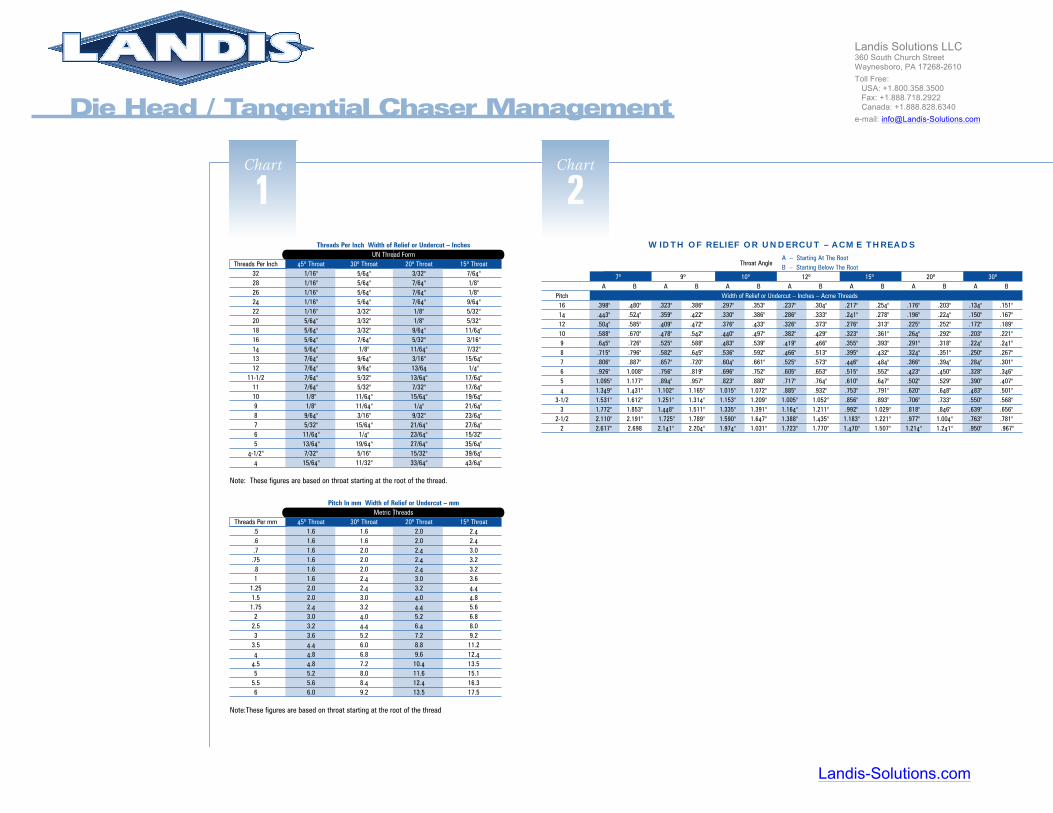
Threads Per Inch Width of Relief or Undercut – InchesUN Thread Form
Threads Per Inch 45º Throat 30º Throat 20º Throat 15º Throat32 1/16" 5/64" 3/32" 7/64"28 1/16" 5/64" 7/64" 1/8"26 1/16" 5/64" 7/64" 1/8"24 1/16" 5/64" 7/64" 9/64"22 1/16" 3/32" 1/8" 5/32"20 5/64" 3/32" 1/8" 5/32"18 5/64" 3/32" 9/64" 11/64"16 5/64" 7/64" 5/32" 3/16"14 5/64" 1/8" 11/64" 7/32"13 7/64" 9/64" 3/16" 15/64"12 7/64" 9/64" 13/64 1/4"
11-1/2 7/64" 5/32" 13/64" 17/64"11 7/64" 5/32" 7/32" 17/64"10 1/8" 11/64" 15/64" 19/64"9 1/8" 11/64" 1/4" 21/64"8 9/64" 3/16" 9/32" 23/64"7 5/32" 15/64" 21/64" 27/64"6 11/64" 1/4" 23/64" 15/32"5 13/64" 19/64" 27/64" 35/64"
4-1/2" 7/32" 5/16" 15/32" 39/64"4 15/64" 11/32" 33/64" 43/64"
Note: These figures are based on throat starting at the root of the thread.
Pitch In mm Width of Relief or Undercut – mmMetric Threads
Threads Per mm 45º Throat 30º Throat 20º Throat 15º Throat.5 1.6 1.6 2.0 2.4.6 1.6 1.6 2.0 2.4.7 1.6 2.0 2.4 3.0.75 1.6 2.0 2.4 3.2.8 1.6 2.0 2.4 3.21 1.6 2.4 3.0 3.6
1.25 2.0 2.4 3.2 4.41.5 2.0 3.0 4.0 4.81.75 2.4 3.2 4.4 5.6
2 3.0 4.0 5.2 6.82.5 3.2 4.4 6.4 8.03 3.6 5.2 7.2 9.2
3.5 4.4 6.0 8.8 11.24 4.8 6.8 9.6 12.4
4.5 4.8 7.2 10.4 13.55 5.2 8.0 11.6 15.1
5.5 5.6 8.4 12.4 16.36 6.0 9.2 13.5 17.5
Note:These figures are based on throat starting at the root of the thread
Chart
1WIDTH OF RELIEF OR UNDERCUT – ACME THREADS
Throat AngleA -- Starting At The RootB -- Starting Below The Root
7º 9º 10º 12º 15º 20º 30ºA B A B A B A B A B A B A B
Pitch Width of Relief or Undercut – Inches – Acme Threads16 .398" .480" .323" .386" .297" .353" .237" .304" .217" .254" .176" .203" .134" .151"14 .443" .524" .359" .422" .330" .386" .286" .333" .241" .278" .196" .224" .150" .167"12 .504" .585" .409" .472" .376" .433" .326" .373" .276" .313" .225" .252" .172" .189"10 .588" .670" .478" .542" .440" .497" .382" .429" .323" .361" .264" .292" .203" .221"9 .645" .726" .525" .588" .483" .539" .419" .466" .355" .393" .291" .318" .224" .241"8 .715" .796" .582" .645" .536" .592" .466" .513" .395" .432" .324" .351" .250" .267"7 .806" .887" .657" .720" .604" .661" .525" .573" .446" .484" .366" .394" .284" .301"6 .926" 1.008" .756" .819" .696" .752" .605" .653" .515" .552" .423" .450" .328" .346"5 1.095" 1.177" .894" .957" .823" .880" .717" .764" .610" .647" .502" .529" .390" .407"4 1.349" 1.431" 1.102" 1.165" 1.015" 1.072" .885" .932" .753" .791" .620" .648" .483" .501"
3-1/2 1.531" 1.612" 1.251" 1.314" 1.153" 1.209" 1.005" 1.052" .856" .893" .706" .733" .550" .568"3 1.772" 1.853" 1.448" 1.511" 1.335" 1.391" 1.164" 1.211" .992" 1.029" .818" .846" .639" .656"
2-1/2 2.110" 2.191" 1.725" 1.789" 1.590" 1.647" 1.388" 1.435" 1.183" 1.221" .977" 1.004" .763" .781"2 2.617" 2.698 2.141" 2.204" 1.974" 1.031" 1.723" 1.770" 1.470" 1.507" 1.214" 1.241" .950" .967"
Chart
2
Die Head / Tangential Chaser Management
Landis-Solutions.com
Landis Solutions LLC 360 South Church Street Waynesboro, PA 17268-2610
Toll Free: USA: +1.800.358.3500 Fax: +1.888.718.2922 Canada: +1.888.828.6340
e-mail: [email protected]

Chart
1PROBLEM CAUSE
External Threading Problems: Causes And CuresIn addition to this quick reference chart, more complete information on threading problems iscontained in “Die Head/Tangential Chaser Management.”
PROBLEM: ROUGH THREADS
Chasers set too far above or over center Set to gage position and/or adjust all chasers of the set back equally.
Cutting rake ground too low for the material Start with rake angle recommended by Landis for the material.Vary if necessary to obtain best results.
Misalignment between die head and workpiece Check die head and machine components for both angular and concentric agreement.
Improper starting pressure On hand feedwork, it generally is a matter of an operator’s gaining sufficient experienceto apply proper pressure. Leadscrew and other mechanical starting means such as cams andspring starts, must be correct for the lead of the thread.
Insufficient hook in the lip rake Grind lip rake to factory specified angle.
Welding of chips on cutting edge Increase coolant flow to reduce heat factor, the cause of welding. Use a good grade ofsulfur base cutting oil. Use chasers with sufficiently long throats, especially on coarsepitch work. Also, use a higher rake and grind the cutting end as smooth as possible.
Improper chaser seating Disassemble and clean chaser holders and clamps. Hone away any nicks from clamps andholders that would interfere with proper seating.
Chipped chasers Regrind.
Mixed chaser throat angles Make certain all the throats of the chasers have the same angle. If 20°, all should be 20°.
Low machineability rating Materials with low machineability ratings require that all conditions such as the use ofgood sulfur base coolant, proper chaser throat, correct cutting end geometry and rightspeed be met. Using chasers with roughing and finishing throat will often help.
Speed too fast Use recommended starting speed for the diameter, pitch and material combination.If desired, adjust upward to improve results.
SOLUTION
PROBLEM CAUSE
PROBLEM: CHIPPED CHASERS
Failing to back off die head when opening When stopping under cut to check chaser chip distribution, do not open the head until it hasunder cut been backed off sufficiently to clear the chasers from the cut.
Die head striking shoulder Add sufficient run-out to include the throat length plus a slight allowance to compensate forthe die head’s slight forward movement that occurs during opening. When a leadscrew isbeing used, the leadscrew trip must be set to disengage the screw after the head opens butbefore the head strikes the shoulder.
Grinding burn Grind carefully to prevent burn. Also, do not water quench. Alternate rapid heating andcooling with water causes cracks that may break out in service, although not readily visible.
Rake angle too high or too low A too high rake weakens the edge. Too low rake causes high cutting pressures. Use factoryrecommended rake.
Misalignment Check and correct any angular or concentric misalignment between the die head and work.
Abrupt starting Corrected with experience.
Threading sheared ends Minimize the effect of the shearing operation as much as possible and use chasers with athroat starting sufficiently below the root of thread to remove excess metal and true outthe end.
Work turning in grips Use more gripping pressure or sharper grips.
SOLUTION
Chart
2PROBLEM CAUSE
External Threading Problems: Causes And CuresIn addition to this quick reference chart, more complete information on threading problems iscontained in “Die Head/Tangential Chaser Management.”
PROBLEM: OUT-OF-ROUNDNESS
Chasers set too far back of center Advance all chasers of the set gradually and equally until condition disappears.
Lack of rigidity on the part of the workpiece or Use "centering throat" chasers.the die head
Mixed throats in set Make sure all chasers of the set are of the same throat angle.
Improper chaser seating Clean and/or hone defects of chaser holder seating surfaces and clamps.
Chipped chasers Regrind and/or correct condition causing chipping.
Threading sheared stock Minimize the effect of the shearing operation as much as possible and use chasers with athroat starting sufficiently below the root of thread to remove excess metal and true outthe end.
Using improper rake angle Use factory recommended rake angle to cut the material.
SOLUTION
PROBLEM CAUSE
PROBLEM: TAPERED THREADS
Threading hard or abrasive material When using Heat Treated style heads, hard materials bellmouth the chaser holdersdestroying chaser clearance to cause cutting across the entire width, thus producing atapered thread. Use chasers with more heel clearance. Abrasive materials dub the cuttingsurfaces which also destroys the chaser clearance of Heat Treated heads. Request harderchasers to improve cutting action and obtain longer running time.
Misalignment Correct any misalignment between die head, machine and work.
Poor starting Improper hand feed side shaves the flank and can appear to be tapered on the beginningthreads. Correct feed rate through experience.
Excessive backlash in head adjusting worm Take up excess, or, if worm is worn, replace.
Improperly seated chasers. Clean and/or hone away defects of chaser holder seating surfaces and clamps.
Worn head parts Return head to factory for inspection and reconditioning or replace obviously defective partssuch as sprung chaser holders, worn head body, worn trunnions.
SOLUTION
PROBLEM CAUSE
PROBLEM: LEAD ERROR
Incorrect helix angle Use correct chaser holder for the thread series. Where lead is critical, use "special" chaserholder incorporating the correct helix.
Improper chaser setting Check and reset the chasers.
Improper chaser seating Clean and/or hone away defects of chaser holder seating surface and clamps.
Improper chaser clearance Correct any condition affecting clearance, or obtain chasers with different clearance.Reduced clearance increases lead; increased clearance reduces lead.
Improper starting Correct hand starting technique. Check lead of mechanical feed.
Hand feed being used when leadscrew or If lead tolerance of .001" per inch or less is required, the use of leadscrew, precision groundpositive feed is required thread cam or precision feed gears is required.
SOLUTION
NEXT
Landis-Solutions.com
Landis Solutions LLC 360 South Church Street Waynesboro, PA 17268-2610
Toll Free: USA: +1.800.358.3500 Fax: +1.888.718.2922 Canada: +1.888.828.6340
e-mail: [email protected]

Chart
3PROBLEM CAUSE
External Threading Problems: Causes And CuresIn addition to this quick reference chart, more complete information on threading problems iscontained in “Die Head/Tangential Chaser Management.”
PROBLEM: SIDE SHAVE
Misalignment between die head, machine and Check angular and concentric alignment and correct.workpiece
Trunnion play or clearance not uniformly set Reset to factory recommendations.
Improper chaser seating Clean and/or hone chaser holder seating surfaces and clamps.
Improper hand start Improve starting technique.
Improper chaser grind Review recommended grinds and regrind chasers.
Worn head parts Inspect and replace as required or return for factory inspection and recommendations.
Work turns in grips when using leadscrew feed Use greater gripping pressure or sharpen grips.
SOLUTION
PROBLEM CAUSE
PROBLEM: DRUNKEN THREADS
Chasers set too far back of center Advance all chasers of the set equally until condition disappears.
Misalignment Correct as required. Drunkenness is most likely caused by an off-square condition,not eccentricity.
Improper feed Improve hand feed technique. Check lead of mechanical feed.
Improper chaser seating Inspect, clean and/or hone defects on chaser holders and clamps.
Worn head parts Replace worn parts or return head to factory for inspection and rebuild.
SOLUTION
PROBLEM CAUSE
PROBLEM: CHATTER
Chaser set too far back of center Advance all chasers equally until chatter disappears.
Cutting rake too high Grind chasers to factory recommended angle for the material being threaded.
Lack of rigidity on the part of the Inspect die head and machine components and correct as required.die head or workpiece
Too much hook in lip rake Regrind chasers to recommended rake.
Chipped chasers Regrind chasers.
Mixed chaser throats Replace chasers as required.
SOLUTION
Landis-Solutions.com
Landis Solutions LLC 360 South Church Street Waynesboro, PA 17268-2610
Toll Free: USA: +1.800.358.3500 Fax: +1.888.718.2922 Canada: +1.888.828.6340
e-mail: [email protected]