To hear today’s event : Listen via the audio stream...
63
© 2012 ANSYS, Inc. November 27, 2014 1 To hear today’s event : Listen via the audio stream through your computer speakers OR Listen via phone by clicking the teleconference request button in the Participants window You will not hear “hold music” while waiting for the event to begin.
-
Upload
truongliem -
Category
Documents
-
view
220 -
download
5
Transcript of To hear today’s event : Listen via the audio stream...

© 2012 ANSYS, Inc. November 27, 2014
1
To hear today’s event : Listen via the audio stream through your
computer speakers OR
Listen via phone by clicking the teleconference request button in the
Participants window
You will not hear “hold music” while waiting for the event to begin.
© 2012 ANSYS, Inc. November 27, 2014
2
Power Electronics for Hybrid and Electric Vehicles
Mark Solveson – Application Engineer
© 2012 ANSYS, Inc. November 27, 2014
3
Simplorer Capabilities, Components, Semiconductors
Thermal performance Power Electronics Examples
System Deisgn Integration PExprt – EMI, RMxprt Maxwell Automotive system Examples
Power Electronics for Hybrid and Electric Vehicles
© 2012 ANSYS, Inc. November 27, 2014
4
10・15モード
0
10
20
30
40
50
60
70
80
0 100 200 300 400 500 600 700
時間(s)
車速(km/h)
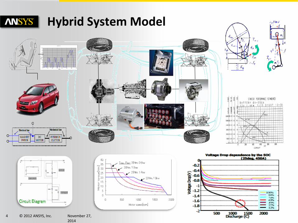
Hybrid System Model
© 2012 ANSYS, Inc. November 27, 2014
5
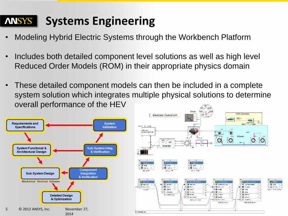
Systems Engineering • Modeling Hybrid Electric Systems through the Workbench Platform
• Includes both detailed component level solutions as well as high level
Reduced Order Models (ROM) in their appropriate physics domain
• These detailed component models can then be included in a complete
system solution which integrates multiple physical solutions to determine
overall performance of the HEV
© 2012 ANSYS, Inc. November 27, 2014
6
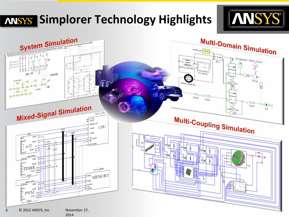
Simplorer Technology Highlights
© 2012 ANSYS, Inc. November 27, 2014
7
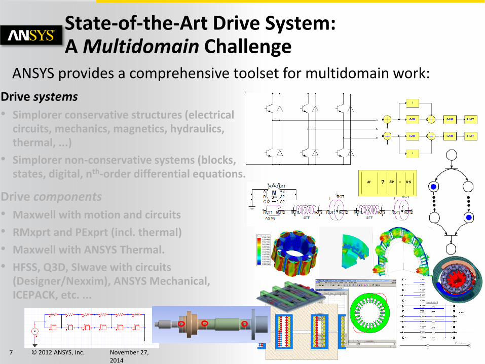
State-of-the-Art Drive System: A Multidomain Challenge
Drive systems
• Simplorer conservative structures (electrical circuits, mechanics, magnetics, hydraulics, thermal, ...)
• Simplorer non-conservative systems (blocks, states, digital, nth-order differential equations.
Drive components
• Maxwell with motion and circuits
• RMxprt and PExprt (incl. thermal)
• Maxwell with ANSYS Thermal.
• HFSS, Q3D, SIwave with circuits (Designer/Nexxim), ANSYS Mechanical, ICEPACK, etc. ...
ANSYS provides a comprehensive toolset for multidomain work:
? = M SV RS
© 2012 ANSYS, Inc. November 27, 2014
8
+
-
B 11A 11 C11
A 12 A 2
B 12 B 2
C12 C2
ROT2ROT1
ASMS
3~M
J
STF
M(t)
GN
D
m
STF
F(t)
GN
D
Magnetics
JA
MMF
Mechanics
L
H Q
Hydraulics, Thermal, ...
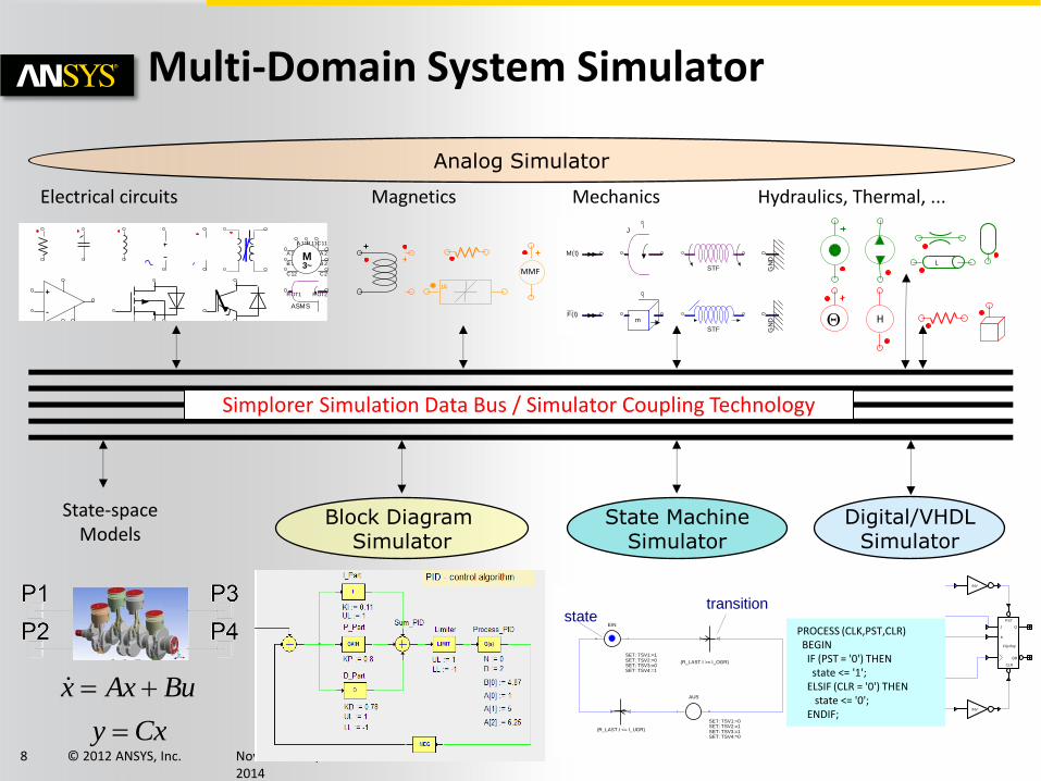
Simplorer Simulation Data Bus / Simulator Coupling Technology
State-space Models
statetransition
AUS
SET: TSV1:=0SET: TSV2:=1SET: TSV3:=1SET: TSV4:=0
(R_LAST.I <= I_UGR)
(R_LAST.I >= I_OGR)
EIN
SET: TSV1:=1SET: TSV2:=0SET: TSV3:=0SET: TSV4:=1
Cxy
BuAxx
Electrical circuits
Multi-Domain System Simulator
Analog Simulator
Block Diagram Simulator
State Machine Simulator
Digital/VHDL Simulator
PROCESS (CLK,PST,CLR) BEGIN IF (PST = '0') THEN state <= '1'; ELSIF (CLR = '0') THEN state <= '0'; ENDIF;
JK-Flip flop with Active-low Preset and Clear
CLK
INV
CLK
CLK
J Q
QB
CLR
PST
Flip flop
K
CLK
CLK
INV
0 0 0 0 1 1 1 1 1 1X-Axis
Curve Data
ffjkcpal1.clk:TR
ffjkcpal1.j:TR
ffjkcpal1.k:TR
ffjkcpal1.clr:TR
ffjkcpal1.pst:TR
ffjkcpal1.q:TR
ffjkcpal1.qb:TR
MX1: 0.1000
© 2012 ANSYS, Inc. November 27, 2014
9
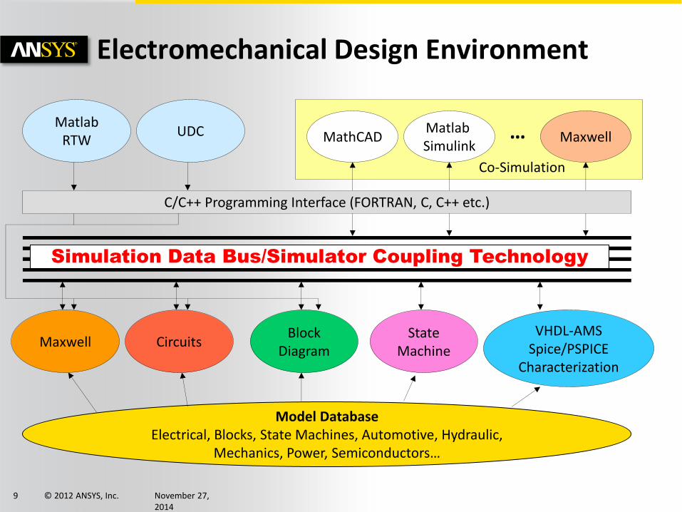
Electromechanical Design Environment
Simulation Data Bus/Simulator Coupling Technology
Model Database Electrical, Blocks, State Machines, Automotive, Hydraulic,
Mechanics, Power, Semiconductors…
Maxwell Circuits Block
Diagram State
Machine
VHDL-AMS Spice/PSPICE
Characterization
Matlab RTW
UDC MathCAD Matlab Simulink
Maxwell
C/C++ Programming Interface (FORTRAN, C, C++ etc.)
…
Co-Simulation
© 2012 ANSYS, Inc. November 27, 2014
10
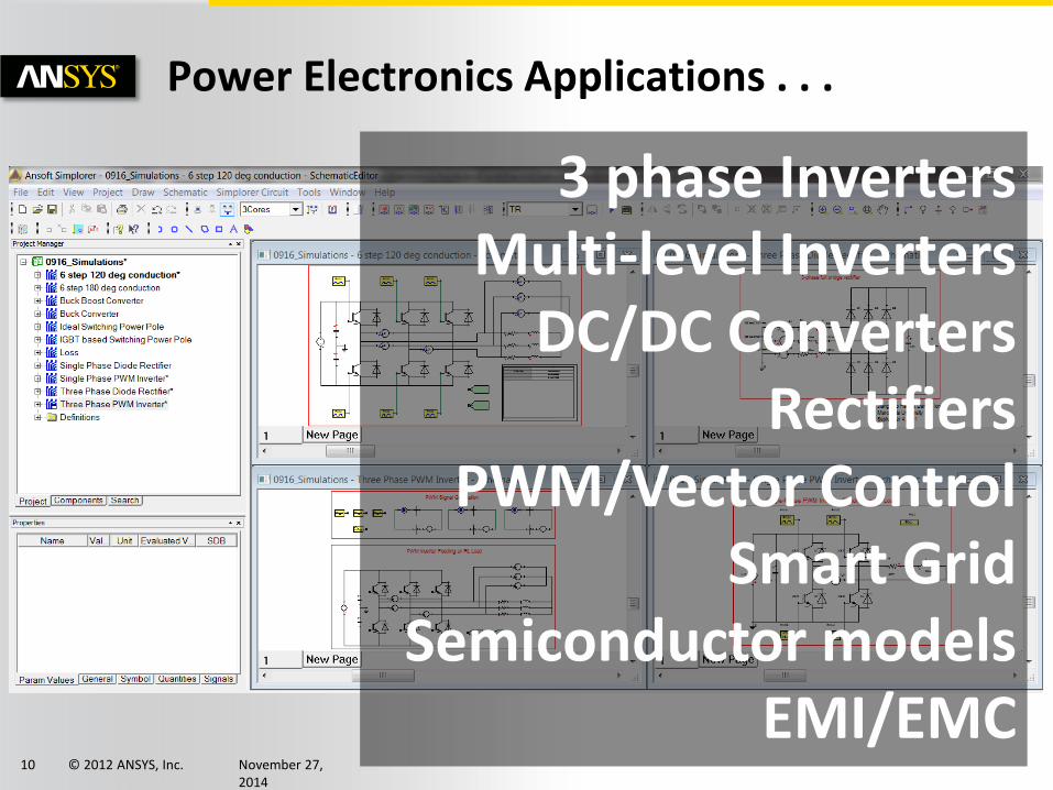
Power Electronics Applications . . .
3 phase Inverters Multi-level Inverters
DC/DC Converters Rectifiers
PWM/Vector Control Smart Grid
Semiconductor models EMI/EMC
© 2012 ANSYS, Inc. November 27, 2014
11
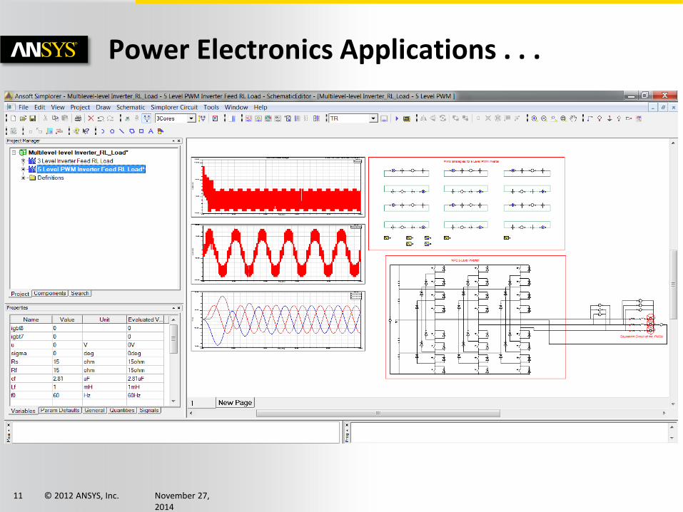
Power Electronics Applications . . .
© 2012 ANSYS, Inc. November 27, 2014
12
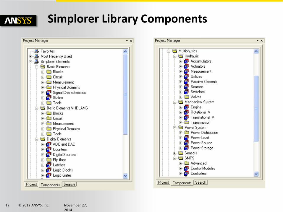
Simplorer Library Components
© 2012 ANSYS, Inc. November 27, 2014
13
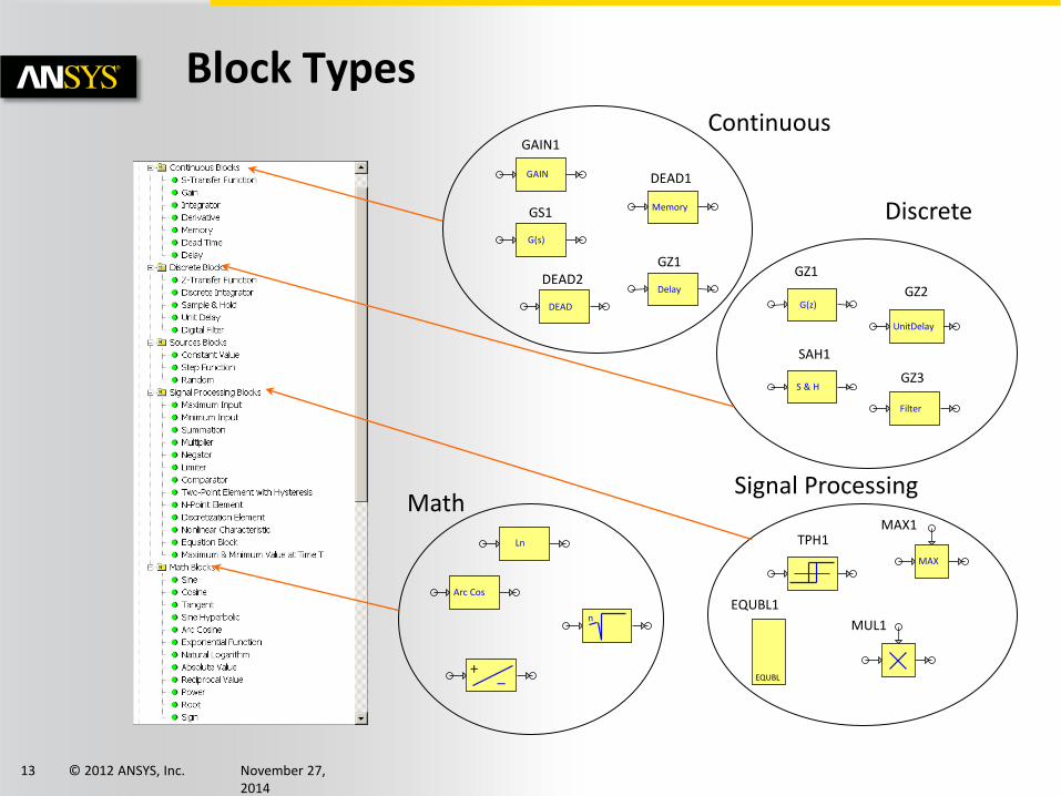
Block Types
GAIN
GAIN1
G(s)
GS1 Memory
DEAD1
Delay
GZ1
DEAD
DEAD2
G(z)
GZ1
S & H
SAH1
UnitDelay
GZ2
Filter
GZ3
Arc Cos
Ln
n
_ +
MAX
MAX1
MUL1
TPH1
EQUBL
EQUBL1
Continuous
Discrete
Signal Processing Math
© 2012 ANSYS, Inc. November 27, 2014
14
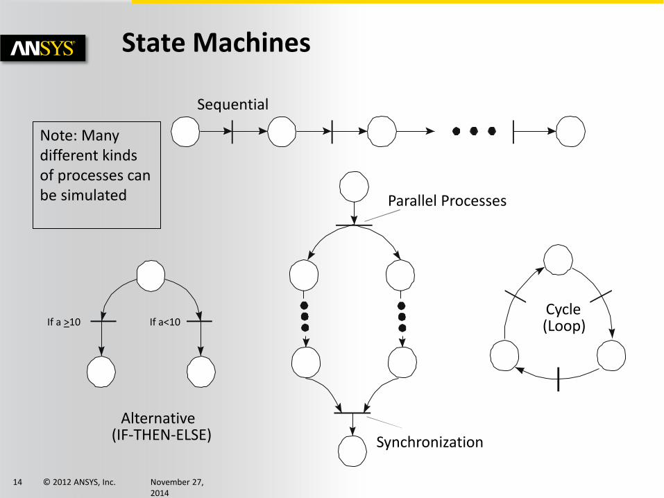
State Machines
Sequential
Parallel Processes
Cycle (Loop)
Synchronization
Alternative (IF-THEN-ELSE)
Note: Many different kinds of processes can be simulated
If a >10 If a<10
© 2012 ANSYS, Inc. November 27, 2014
15
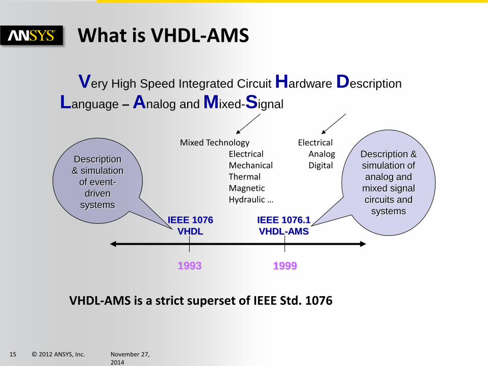
What is VHDL-AMS
VHDL-AMS is a strict superset of IEEE Std. 1076
Very High Speed Integrated Circuit Hardware Description
Language – Analog and Mixed-Signal
1993 1999
IEEE 1076
VHDL
IEEE 1076.1
VHDL-AMS
Description
& simulation
of event-
driven
systems
Description &
simulation of
analog and
mixed signal
circuits and
systems
Mixed Technology Electrical Mechanical Thermal Magnetic Hydraulic …
Electrical Analog Digital
© 2012 ANSYS, Inc. November 27, 2014
16
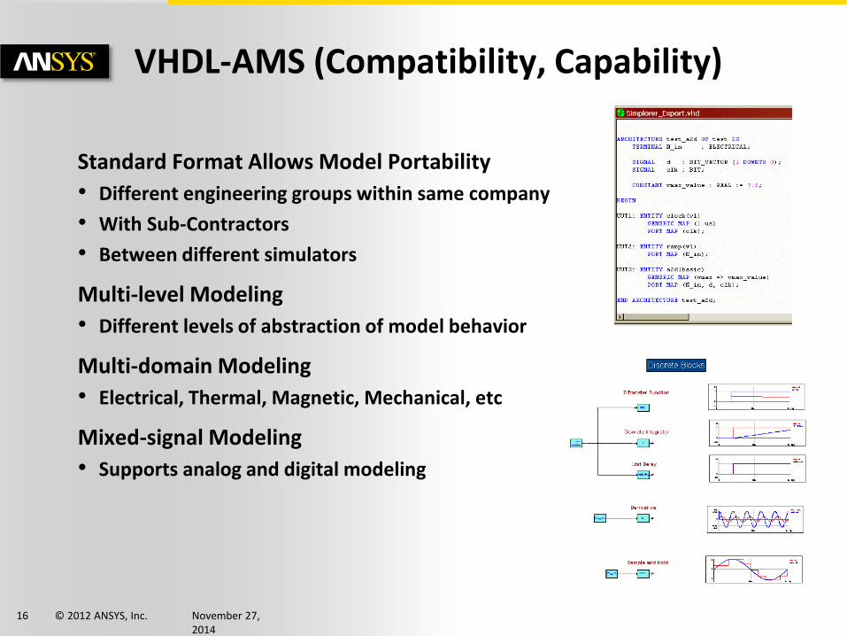
VHDL-AMS (Compatibility, Capability)
Standard Format Allows Model Portability
• Different engineering groups within same company
• With Sub-Contractors
• Between different simulators
Multi-level Modeling
• Different levels of abstraction of model behavior
Multi-domain Modeling
• Electrical, Thermal, Magnetic, Mechanical, etc
Mixed-signal Modeling
• Supports analog and digital modeling

© 2012 ANSYS, Inc. November 27, 2014
17
Why Use VHDL-AMS (Cont’d)
Thermal : Heat flow, Temperature Magnetic : Flux, MMF
© 2012 ANSYS, Inc. November 27, 2014
18
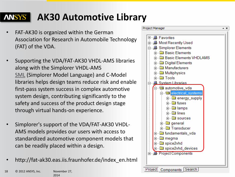
AK30 Automotive Library
• FAT-AK30 is organized within the German Association for Research in Automobile Technology (FAT) of the VDA.
• Supporting the VDA/FAT-AK30 VHDL-AMS libraries along with the Simplorer VHDL-AMS SML (Simplorer Model Language) and C-Model libraries helps design teams reduce risk and enable first-pass system success in complex automotive system design, contributing significantly to the safety and success of the product design stage through virtual hands-on experience.
• Simplorer's support of the VDA/FAT-AK30 VHDL-AMS models provides our users with access to standardized automotive component models that can be readily placed within a design.
• http://fat-ak30.eas.iis.fraunhofer.de/index_en.html
© 2012 ANSYS, Inc. November 27, 2014
19
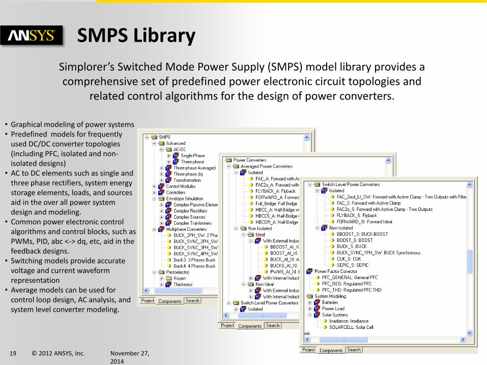
SMPS Library
Simplorer’s Switched Mode Power Supply (SMPS) model library provides a comprehensive set of predefined power electronic circuit topologies and
related control algorithms for the design of power converters.
• Graphical modeling of power systems • Predefined models for frequently
used DC/DC converter topologies (including PFC, isolated and non-isolated designs)
• AC to DC elements such as single and three phase rectifiers, system energy storage elements, loads, and sources aid in the over all power system design and modeling.
• Common power electronic control algorithms and control blocks, such as PWMs, PID, abc <-> dq, etc, aid in the feedback designs.
• Switching models provide accurate voltage and current waveform representation
• Average models can be used for control loop design, AC analysis, and system level converter modeling.
© 2012 ANSYS, Inc. November 27, 2014
20
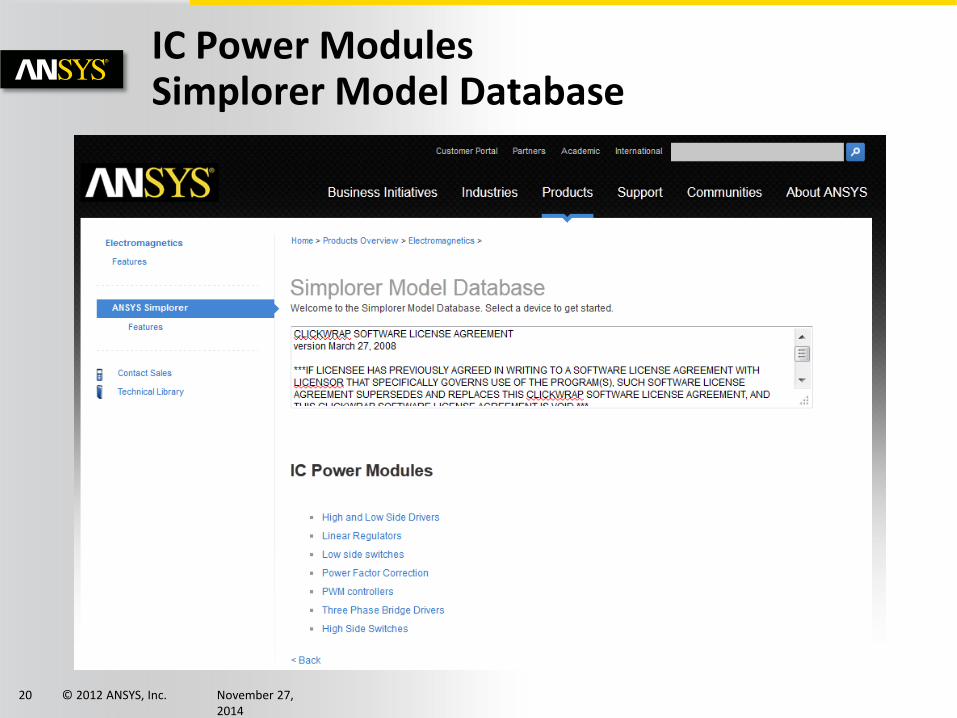
IC Power Modules Simplorer Model Database
© 2012 ANSYS, Inc. November 27, 2014
21
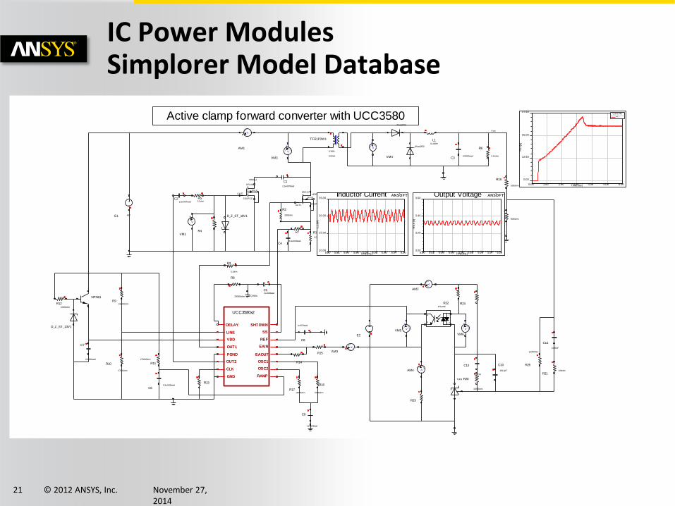
IC Power Modules Simplorer Model Database
Active clamp forward converter with UCC3580
R1
0.05ohm
C1
2.2e-007farad
R2
2000ohm
R4
C22.2e-007farad
R55.1ohm
L15e-006H
C30.0001farad
R6
0.11ohm
+
V
VM1
+
V
VM3
+
V
VM4
A
AM1
E1 48V
R9150000ohm
R10
27000ohm
C7
0.0001farad
R1210000ohm
NPN61
R11
270000ohm
C63.3e-010farad
R8
200000ohm
R3
5.1ohm
C52e-008farad
R7
C48.2e-010farad
R13
R1718000ohm
R16
72800ohm
C9
1e-010farad
R14
R15
C8
1e-007farad
R18
1600ohm
R19 5000ohm
R22
R23
E2
+
VVM5
AAM3
+
V
VM6
R24
AAM4
1
23
4
PS2705
A
AM2
TL431 R20
10000ohm
C12
4.472nF
C10
159.2pF
R25
12000ohm
R21438ohm
C11
3.635nF
TFR1P2W1
0.001H
0.1666
DRAIN
BULK
SOURCEGATE
irf6401
_40cpq0601
_40cpq0602
D_Z_ST_18V1
D_Z_ST_13V1
GND
PGND
OUT2
OUT1
RAMP
EAOUT
EAIN
REF
DELAY
VDD
LINE
SHTDWN
SS
CLK OSC2
OSC1
UCC3580x2
UCC3580x
BULK
DRAIN
GATE
SOURCE
irf9640_1
Vout
5.80 5.82 5.85 5.88 5.90 5.92 5.95 5.97 6.00Time [ms]
20.00
25.00
30.00
35.00
L1
.I [A
]
Inductor Current ANSOFT
5.80 5.82 5.85 5.88 5.90 5.92 5.95 5.97 6.00Time [ms]
3.00
3.20
3.40
3.60
R6
.V [V
]
Output Voltage ANSOFT
0.00 1.00 2.00 3.00 4.00 5.00 6.00Time [ms]
0.00
12.50
25.00
37.50
R6
.I [A
]
Curve Info
R6.I
GND
PGND
OUT2
OUT1
RAMP
EAOUT
EAIN
REF
DELAY
VDD
LINE
SHTDWN
SS
CLK OSC2
OSC1
© 2012 ANSYS, Inc. November 27, 2014
22
+
-
+ V
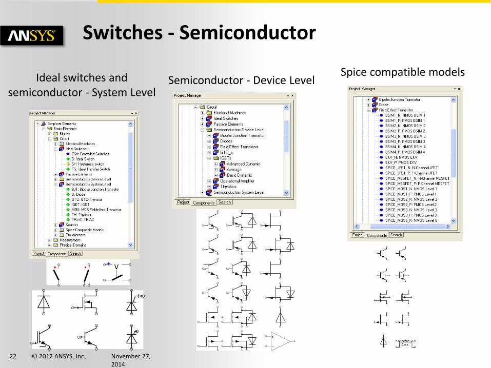
Ideal switches and semiconductor - System Level
Semiconductor - Device Level Spice compatible models
Switches - Semiconductor
© 2012 ANSYS, Inc. November 27, 2014
23
Semicondutor Modeling In Simplorer
IGBT Device model
• Semiconductor device model on Simplorer
• IGBT Device model : Average / Dynamic
• Capability of IGBTmodel
Thermal management for Inverter
• Thermal model in Simplorer’s semiconductor model.
• Extract thermal network from ANSYS Icepak
• Heat / Power loss coupling with device model
Inverter surge and conduction noise
• Extract parasitic LCR from Q3D Extractor
• Inverter surge and conduction noise in Simplorer
© 2012 ANSYS, Inc. November 27, 2014
24
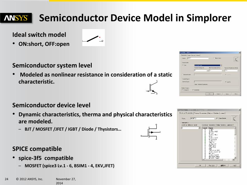
Semiconductor Device Model in Simplorer
Ideal switch model
• ON:short, OFF:open
Semiconductor system level
• Modeled as nonlinear resistance in consideration of a static characteristic.
Semiconductor device level
• Dynamic characteristics, therma and physical characteristics are modeled. – BJT / MOSFET /JFET / IGBT / Diode / Thysistors…
SPICE compatible
• spice-3f5 compatible – MOSFET (spice3 Lv.1 - 6, BSIM1 - 4, EKV,JFET)
© 2012 ANSYS, Inc. November 27, 2014
25
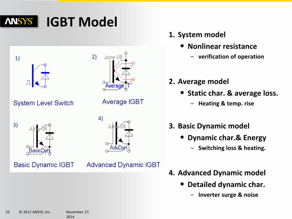
IGBT Model 1. System model
• Nonlinear resistance – verification of operation
2. Average model
• Static char. & average loss. – Heating & temp. rise
3. Basic Dynamic model
• Dynamic char.& Energy – Switching loss & heating.
4. Advanced Dynamic model
• Detailed dynamic char. – Inverter surge & noise
1) 2)
3) 4)
© 2012 ANSYS, Inc. November 27, 2014
26
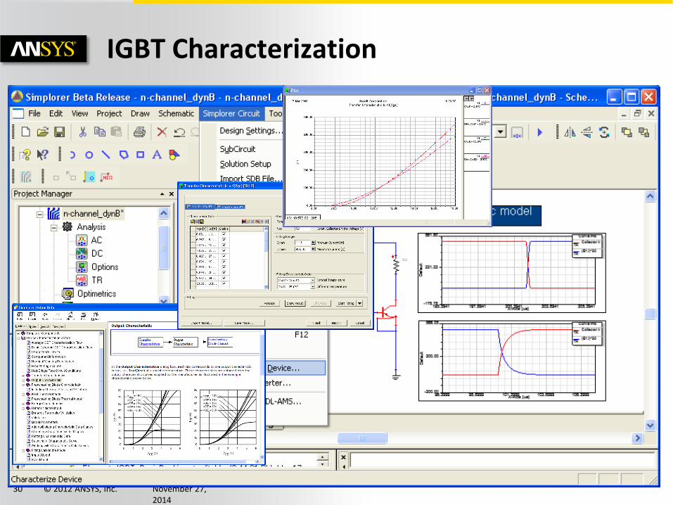
IGBT Characterization
• Average model is developed for system simulation and is integrated into the extraction tool
• Common thermal model is used among the IGBT family members
© 2012 ANSYS, Inc. November 27, 2014
27
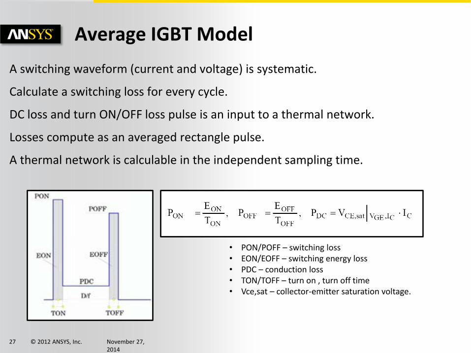
Average IGBT Model
A switching waveform (current and voltage) is systematic.
Calculate a switching loss for every cycle.
DC loss and turn ON/OFF loss pulse is an input to a thermal network.
Losses compute as an averaged rectangle pulse.
A thermal network is calculable in the independent sampling time.
• PON/POFF – switching loss • EON/EOFF – switching energy loss • PDC – conduction loss • TON/TOFF – turn on , turn off time • Vce,sat – collector-emitter saturation voltage.
© 2012 ANSYS, Inc. November 27, 2014
28
-231.0n 618.0n0 200.0n 400.0n
-50.0
700.0
0
166.7
333.3
500.0
-172.0n 750.0n0 200.0n 400.0n 600.0n
-50.0
700.0
0
166.7
333.3
500.0
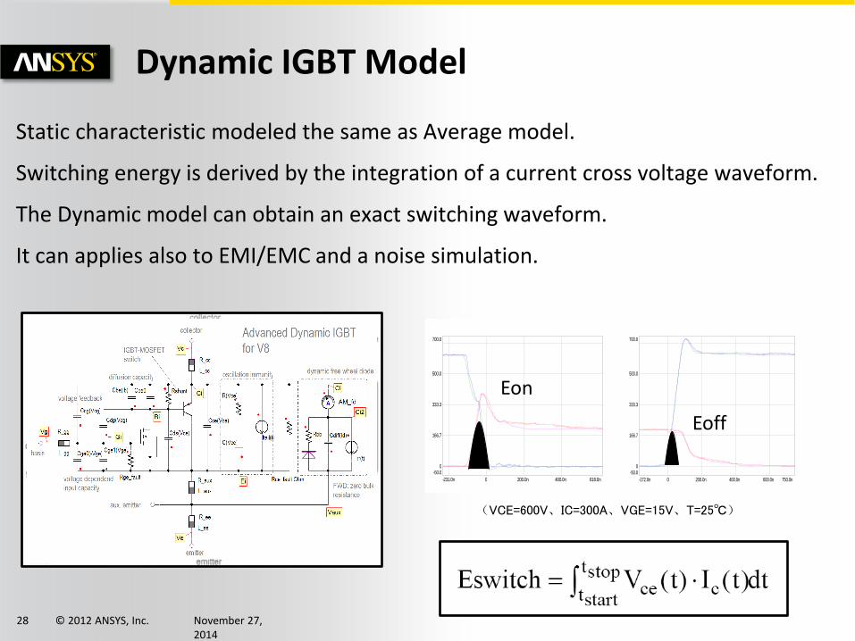
Dynamic IGBT Model
Static characteristic modeled the same as Average model.
Switching energy is derived by the integration of a current cross voltage waveform.
The Dynamic model can obtain an exact switching waveform.
It can applies also to EMI/EMC and a noise simulation.
(VCE=600V、IC=300A、VGE=15V、T=25℃)
Eoff
Eon
© 2012 ANSYS, Inc. November 27, 2014
29
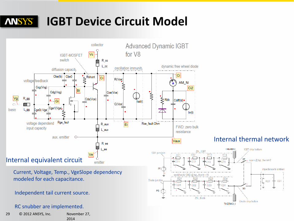
IGBT Device Circuit Model
Internal equivalent circuit
Internal thermal network
Current, Voltage, Temp., VgeSlope dependency modeled for each capacitance. Independent tail current source. RC snubber are implemented.
© 2012 ANSYS, Inc. November 27, 2014
30
IGBT Characterization
© 2012 ANSYS, Inc. November 27, 2014
31
-231.0n 618.0n0 200.0n 400.0n
-50.0
700.0
0
166.7
333.3
500.0
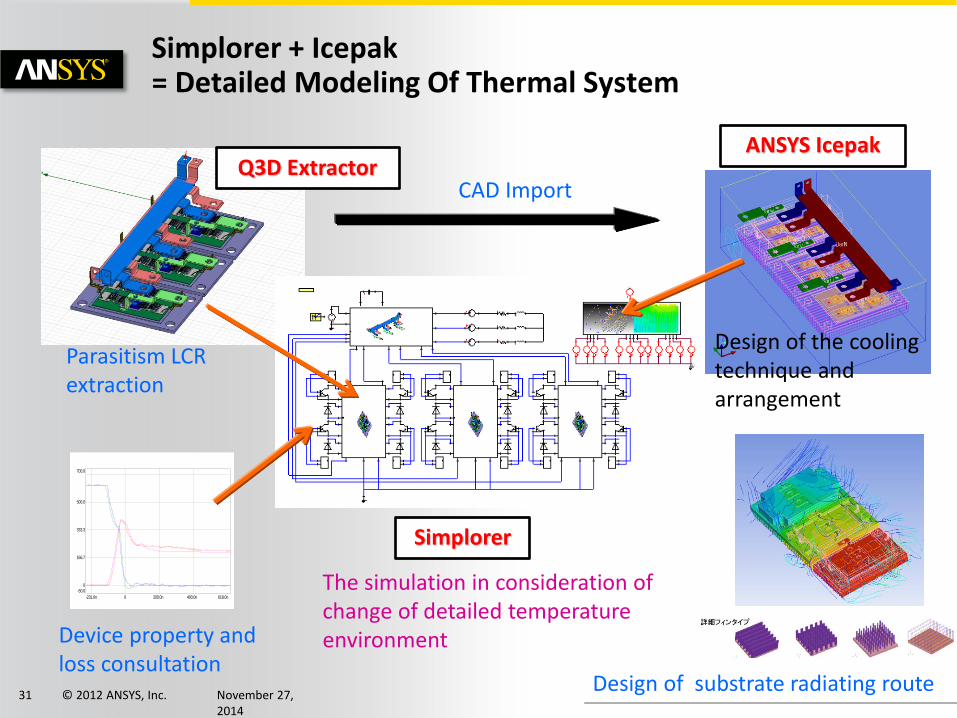
Simplorer + Icepak = Detailed Modeling Of Thermal System
Simplorer
ANSYS Icepak Q3D Extractor
Parasitism LCR extraction
Device property and loss consultation
CAD Import
Design of the cooling technique and arrangement
Design of substrate radiating route
The simulation in consideration of change of detailed temperature environment
© 2012 ANSYS, Inc. November 27, 2014
32
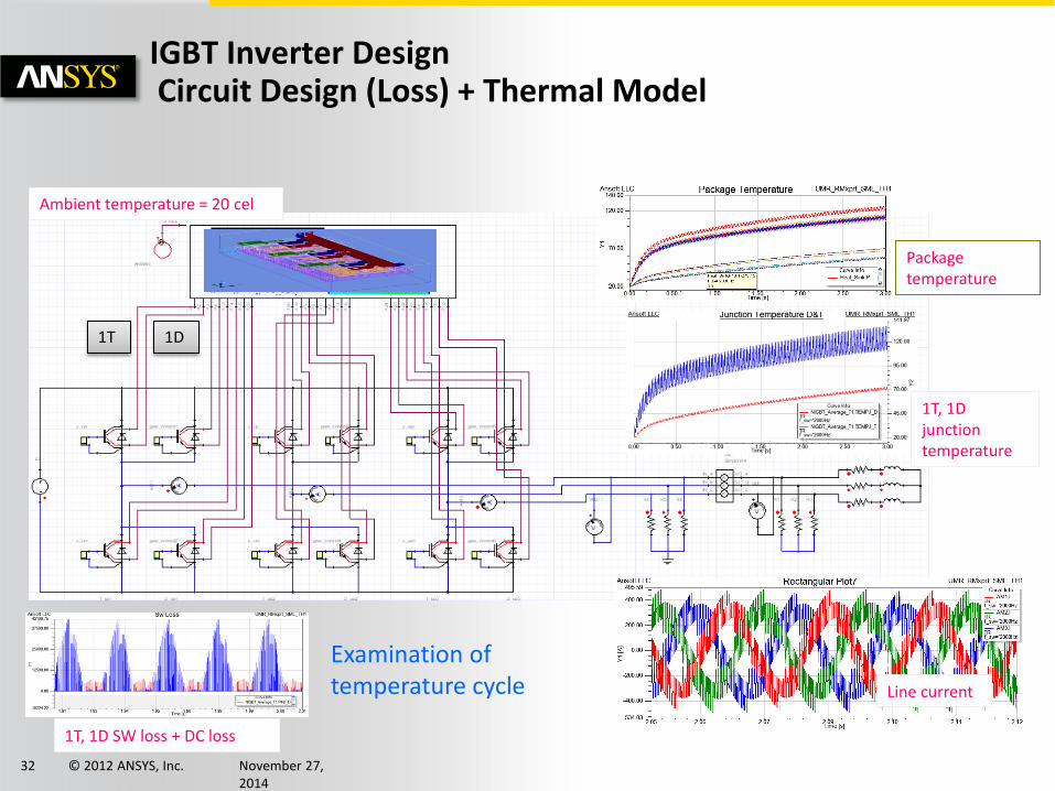
IGBT Inverter Design Circuit Design (Loss) + Thermal Model
Line current
1T, 1D SW loss + DC loss
1T, 1D junction temperature
Package temperature
Examination of temperature cycle
1T 1D
Ambient temperature = 20 cel
© 2012 ANSYS, Inc. November 27, 2014
33
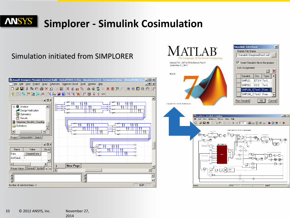
Simulation initiated from SIMPLORER
Simplorer - Simulink Cosimulation
© 2012 ANSYS, Inc. November 27, 2014
34
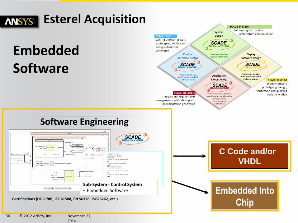
Embedded Into
Chip
Esterel Acquisition
C Code and/or
VHDL
Software Engineering
Certifications (DO-178B, IEC 61508, EN 50128, ISO26262, etc.)
[…]
switch (SSM_SM1_dispatch_sel) { case SSM_SM1_Locked__ABC_N : outC->foreground = white_ABC_N; outC->background = green_ABC_N; if (inC->Unlock) { outC->M_pre_ = SSM_SM1_Preselected__ABC_N; } else { outC->M_pre_ = SSM_SM1_Locked__ABC_N; } break; case SSM_SM1_WaitUnlock__ABC_N : outC->foreground = black_ABC_N; outC->background = grey_ABC_N; if (inC->Unlock) { outC->M_pre_ = SSM_SM1_Unselected__ABC_N; } else { outC->M_pre_ = SSM_SM1_WaitUnlock__ABC_N; } break; […]
Sub-System - Control System • Embedded Software
Embedded Software
© 2012 ANSYS, Inc. November 27, 2014
35
System Analysis Examples
© 2012 ANSYS, Inc. November 27, 2014
36
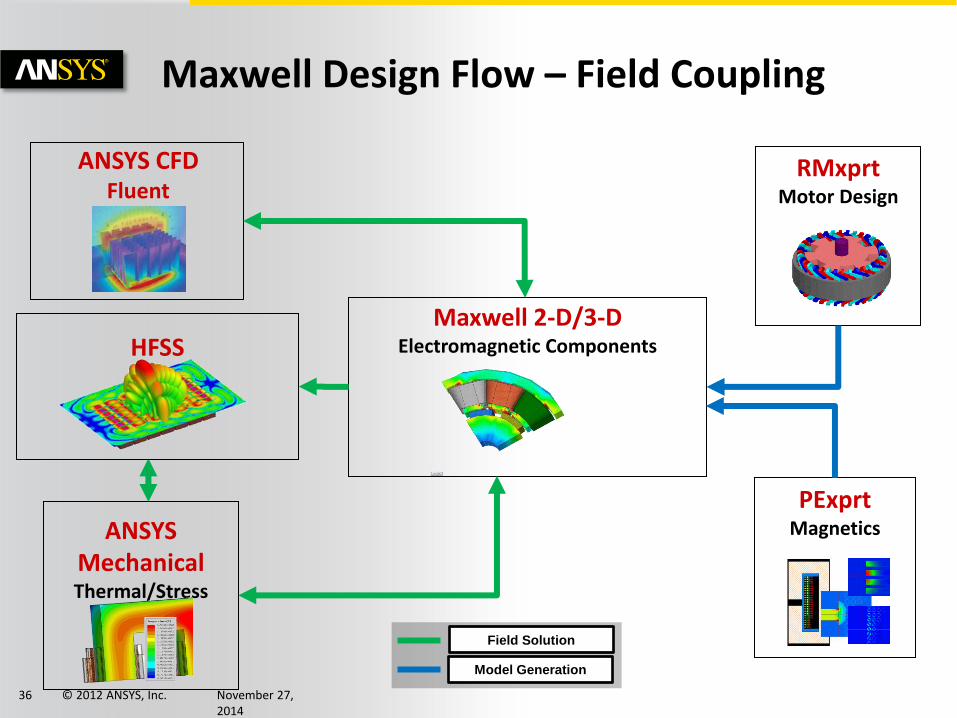
Maxwell 2-D/3-D Electromagnetic Components
Field Solution
Model Generation
HFSS
ANSYS
Mechanical Thermal/Stress
ANSYS CFD Fluent
PExprt Magnetics
RMxprt Motor Design
Maxwell Design Flow – Field Coupling
© 2012 ANSYS, Inc. November 27, 2014
37
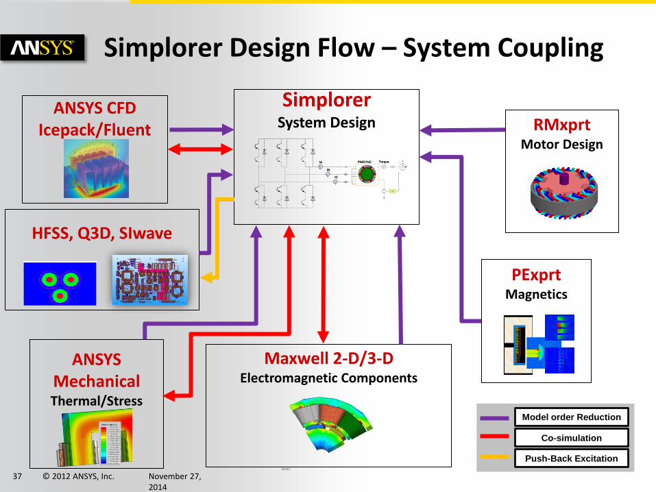
Simplorer System Design
PP := 6
ICA:
A
A
A
GAIN
A
A
A
GAIN
A
JPMSYNCIA
IB
IC
Torque JPMSYNCIA
IB
IC
Torque
D2D
HFSS, Q3D, SIwave
ANSYS CFD Icepack/Fluent
Maxwell 2-D/3-D Electromagnetic Components
ANSYS
Mechanical Thermal/Stress
PExprt Magnetics
RMxprt Motor Design
Simplorer Design Flow – System Coupling
Model order Reduction
Co-simulation
Push-Back Excitation
© 2012 ANSYS, Inc. November 27, 2014
38
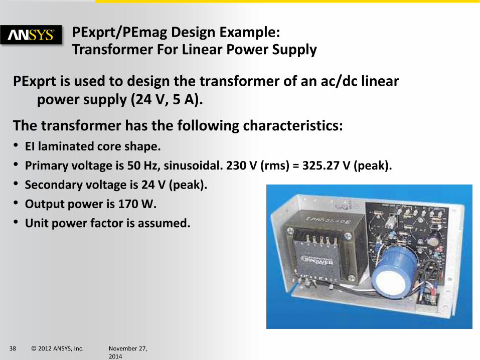
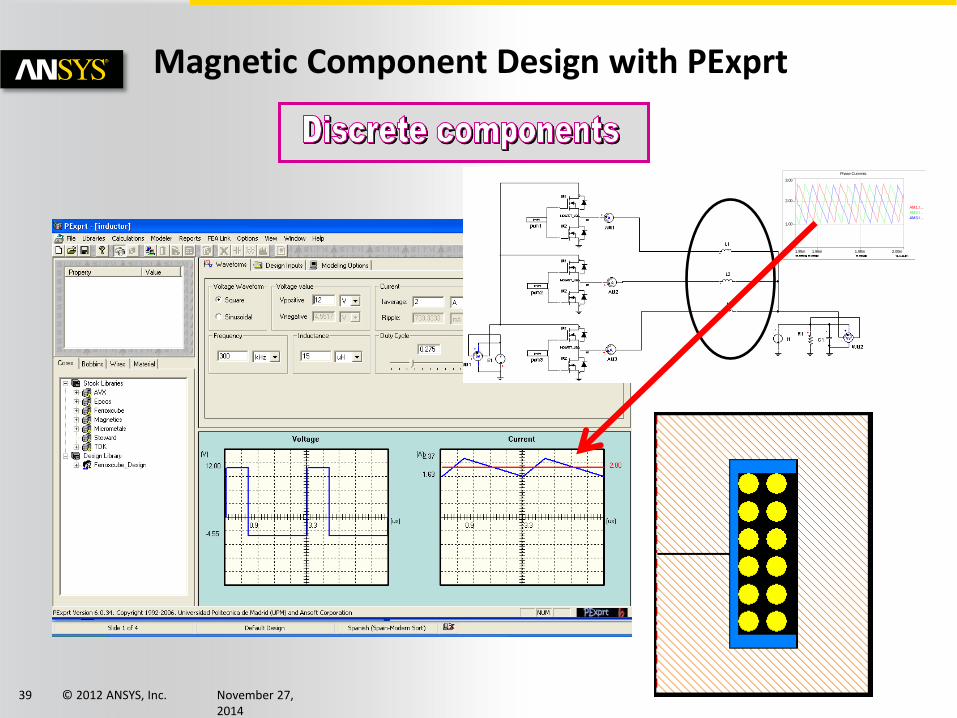
PExprt/PEmag Design Example: Transformer For Linear Power Supply
PExprt is used to design the transformer of an ac/dc linear power supply (24 V, 5 A).
The transformer has the following characteristics: • EI laminated core shape.
• Primary voltage is 50 Hz, sinusoidal. 230 V (rms) = 325.27 V (peak).
• Secondary voltage is 24 V (peak).
• Output power is 170 W.
• Unit power factor is assumed.
© 2012 ANSYS, Inc. November 27, 2014
39
0
3.00
1.00
2.00
1.95m 2.00m1.96m 1.98m
Phase Currents
AM1.I ...
AM2.I ...
AM3.I ...
Magnetic Component Design with PExprt
© 2012 ANSYS, Inc. November 27, 2014
40
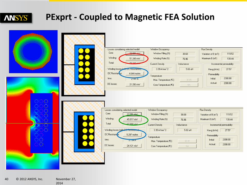
PExprt - Coupled to Magnetic FEA Solution
© 2012 ANSYS, Inc. November 27, 2014
41
snubber
input
Output
push pull transformer inplemented
using coupled inductors for speed, robustness
inputs include main Inductance, leakage Inductance,
wire resistance, coupling coeff "k"
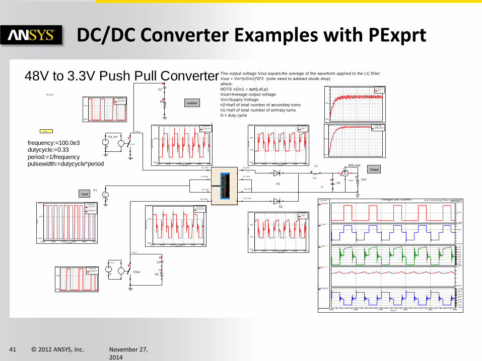
The output v oltage Vout equals the av erage of the wav ef orm applied to the LC f ilter:
Vout = Vin*(n2/n1)*D*2 = 48*0.127*0.33*2 = 4 (note minus diode drop now = 3.3V
where:
NOTE n2/n1 = sqrt(Ls/Lp) = sqrt(20uH/1250uH)
= sqrt(0.016) = 0.127
Vout=Av erage output v oltage
Vin=Supply Voltage
n2=half of total number of secondary turns
n1=half of total number of primary turns
D = duty cy cle
48V to 3.3V Push Pull Converter
0
E1
48V
R17
0.5ohm
C6
5uF
L1
7.5uH
CSx1
CSx2
D1
D2
W
+
WM_load
R1
C1
R4
C2
4 Coupled Inductors
La
Lb
Lc
Ld
coupled_ind_w_leak_r1
coupled_ind_w_leak_r
ICA:
FML_INIT1
frequency:=100.0e3
dutycycle:=0.33
period:=1/frequency
pulsewidth:=dutycycle*period
Ea_inv
Eb_inv
Vsw_b
Vc
Vsw_a
-15.00
5.00
16.50 Curve Info
Ea_inv...TR
-15.00
5.00
16.50 Curve Info
Eb_inv...TR
0.00
5.00
10.00Curve Info
L1.ITR
0.00
2.00
3.52Curve Info
WM_load...TR
150.00 160.00 170.00 180.00 190.00 200.00Time [us]
0.00
100.00
Vsw
_a.V
[V
]
Curve Info
Vsw_a...TR
150.00 160.00 170.00 180.00 190.00 200.00Time [us]
0.00
100.00
Vsw
_b.V
[V
]
Curve Info
Vsw_b...TR
150.00 160.00 170.00 180.00 190.00 200.00Time [us]
-15.00
5.00
16.50
Y1 [V
]
Curve Info
Ea_inv...TR
Eb_inv...TR
150.00 160.00 170.00 180.00 190.00 200.00Time [us]
-5.00
0.00
5.00
10.00
D1.I [A
]
Curve Info
D1.ITR
150.00 160.00 170.00 180.00 190.00 200.00Time [us]
-5.00
0.00
5.00
10.00
D2.I [A
]
Curve Info
D2.ITR
150.00 160.00 170.00 180.00 190.00 200.00Time [us]
-20.00
0.00
20.00
-7.50
2.50
7.50
0.00
7.50
0.00
10.00
0.00
12.50
25.00
37.50
50.00
62.50
75.00
87.50
100.00
Curve Info
Eb_inv...TR
Vc.VTR
D1.ITR
L1.ITR
Vsw_b...TR
DC/DC Converter Examples with PExprt
snubber
input
Output
48V to 3.3V Push Pull Converter The output voltage Vout equals the average of the waveform applied to the LC filter:
Vout = Vin*(n2/n1)*D*2 (note need to subtract diode drop)
where:
NOTE n2/n1 = sqrt(Ls/Lp)
Vout=Average output voltage
Vin=Supply Voltage
n2=half of total number of secondary turns
n1=half of total number of primary turns
D = duty cycle
0
E1
48V
R170.5ohm
C6
5uF
L1
7.5uH
CSx1
CSx2
D1
D2
W
+
WM_load
R1
C1
R4
C2
Ap_center
Am_center
Bp_center
Bm_center
Cp_center
Cm_center
Dp_center
Dm_center
ICA:
FML_INIT1
frequency:=100.0e3dutycycle:=0.33
period:=1/frequencypulsewidth:=dutycycle*period
Ea_inv
Eb_inv
Vsw_b
Vc
Vsw_a
-15.00
5.00
16.50Curve Info
Ea_inv.VTR
-15.00
5.00
16.50Curve Info
Eb_inv.VTR
0.00
5.00
10.00Curve Info
L1.ITR
0.00
2.00
3.75Curve Info
WM_load.VTR
150.00 160.00 170.00 180.00 190.00 200.00Time [us]
-25.00
75.00
127.90
Vsw
_a.V
[V
]
Curve Info
Vsw_a.VTR
150.00 160.00 170.00 180.00 190.00 200.00Time [us]
-25.00
75.00
127.74
Vsw
_b.V
[V
]
Curve Info
Vsw_b.VTR
150.00 160.00 170.00 180.00 190.00 200.00Time [us]
-15.00
5.00
16.50
Y1 [V
]
Curve Info
Ea_inv.VTR
Eb_inv.VTR
150.00 160.00 170.00 180.00 190.00 200.00Time [us]
-5.00
0.00
5.00
10.00
D1.I [A
]
Curve Info
D1.ITR
150.00 160.00 170.00 180.00 190.00 200.00Time [us]
-5.00
0.00
5.00
10.00
D2.I [A
]
Curve Info
D2.ITR
150.00 160.00 170.00 180.00 190.00 200.00Time [us]
-20.00
0.00
20.00
-10.00
2.50
7.50
0.00
1.00
2.00
3.00
4.00
5.00
6.00
7.00
0.00
10.00
-25.00
-5.00
15.00
35.00
55.00
75.00
95.00
115.00
Curve Info
Eb_inv.VTR
Vc.VTR
D1.ITR
L1.ITR
Vsw_b.VTR
push_pull_pwrstg_PExprtVoltages and Currents ANSOFT
© 2012 ANSYS, Inc. November 27, 2014
42
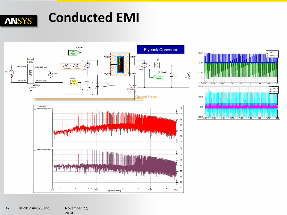
Conducted EMI
© 2012 ANSYS, Inc. November 27, 2014
43
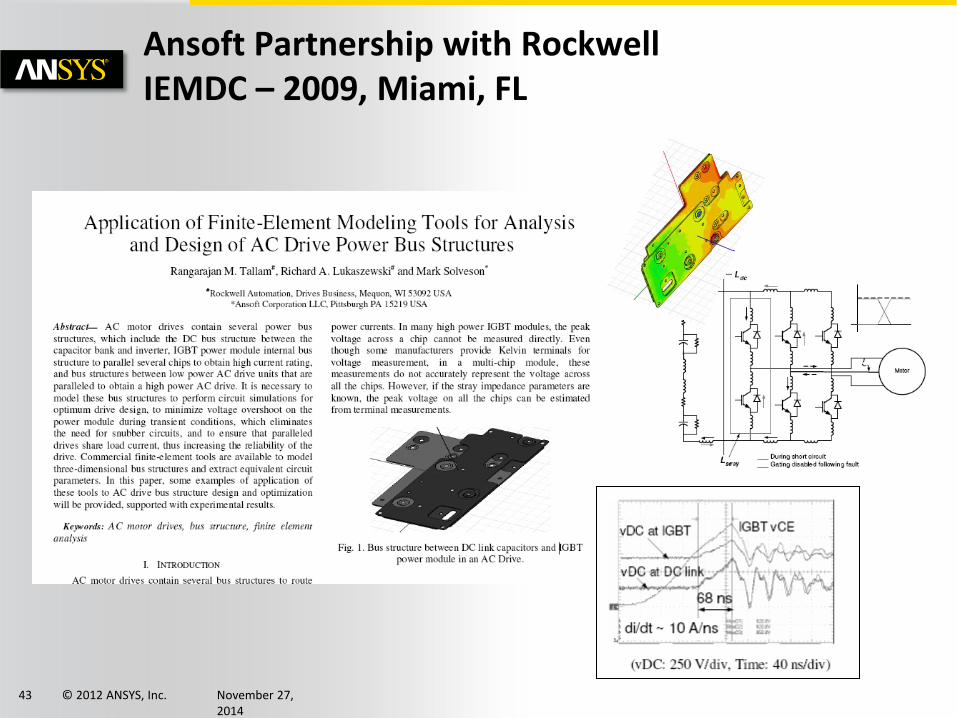
Ansoft Partnership with Rockwell IEMDC – 2009, Miami, FL
© 2012 ANSYS, Inc. November 27, 2014
44
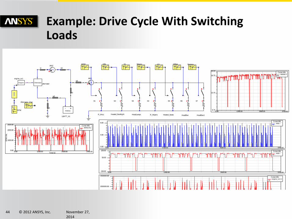
Example: Drive Cycle With Switching Loads
R_Misc Heated_Backlight HeadLamps R_Wipers Heated_Seats HeatBlwr
S1 S2 S3 S4 S5 S6
YtMISC
YtHBL
YtHL
YtWipers
YtHS
YtHBlwr
Yt
RPM
X Y
Alternator_Char
A
AM1
A
AM2 YtMystery
S7
HeatBlwr1
Battery
- +
LBATT_A1
GA
IN
Alternatoralternator
w w1
w2
w3
w4
w5Engine
engine_ss1
0.00 1250.00 2500.00 3750.000.00
500000.00
1000000.00
1500000.00
2000000.00
2500000.00Curve Info
engine_ss1.nTR
0.00 1250.00 2500.00 3750.000.00
4.00
8.00Curve Info
AM1.ITR
0.00 1250.00 2500.00 3750.00-150.00
50.00
150.00 Curve InfoAM2.I
TR
0.00 1250.00 2500.00 3750.008.75
13.75
18.75
20.00Curve Info
N0008.VTR
0.00 1250.00 2500.00 3750.00Time [s]
0.00
1000.00
2000.00
2500.00
RP
M.V
AL
Curve InfoRPM.VAL
TR
© 2012 ANSYS, Inc. November 27, 2014
45
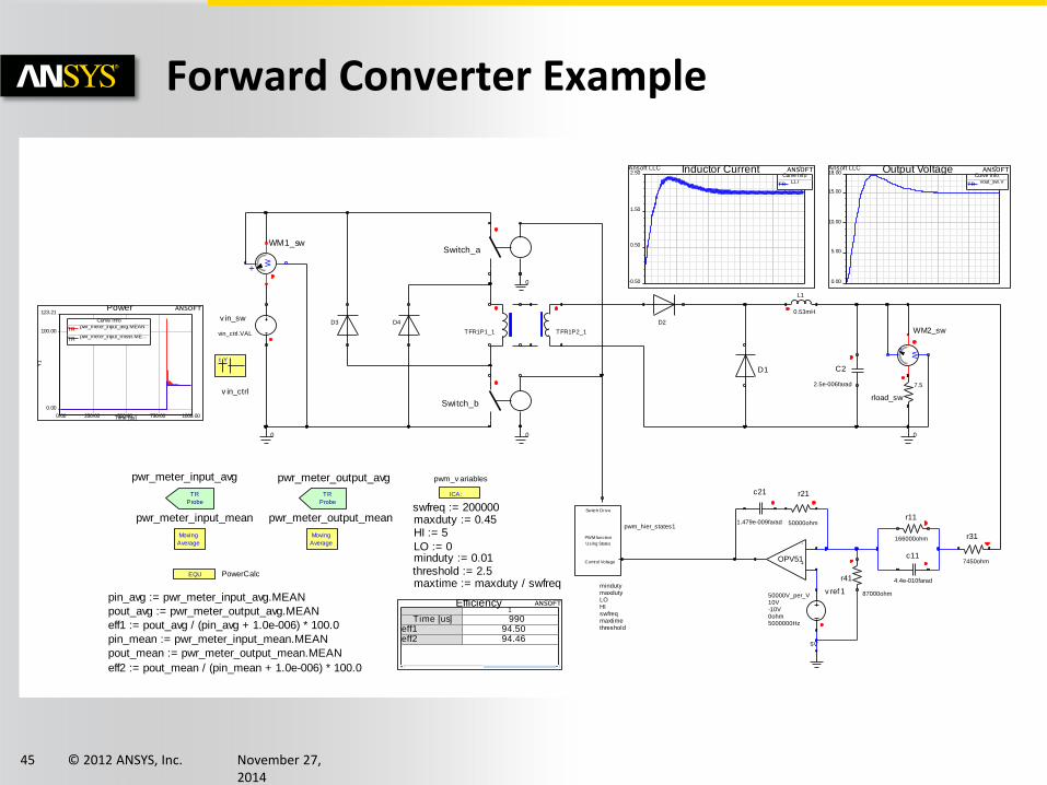
Forward Converter Example
0
00 0
Yt
v in_ctrl
v in_sw
vin_ctrl.VAL
W
+
WM2_sw
rload_sw
7.5
r41
87000ohm
r11
166000ohm
v ref 1
5V
r21
50000ohm
c21
1.479e-009farad
r31
7450ohm
C2
2.5e-006farad
+
-
OPV51
50000V_per_V10V-10V0ohm5000000Hz
c11
4.4e-010farad
ICA:
pwm_v ariables
swfreq := 200000maxduty := 0.45HI := 5
LO := 0minduty := 0.01threshold := 2.5maxtime := maxduty / swfreq
D1
PWM function
Using States
Switch Drive
Control Voltage
pwm_hier_states1
mindutymaxdutyLOHIswfreqmaxtimethreshold
L1
0.53mH
D2
TFR1P2_1
Switch_b
TFR1P1_1
D3 D4
Switch_a
W+WM1_sw
EQU PowerCalc
pin_avg := pwr_meter_input_avg.MEAN
pout_avg := pwr_meter_output_avg.MEAN
eff1 := pout_avg / (pin_avg + 1.0e-006) * 100.0
pin_mean := pwr_meter_input_mean.MEAN
pout_mean := pwr_meter_output_mean.MEAN
eff2 := pout_mean / (pin_mean + 1.0e-006) * 100.0
TR
Probe
pwr_meter_output_avg
TR
Probe
pwr_meter_input_avg
Moving
Average
pwr_meter_input_mean
Moving
Average
pwr_meter_output_mean
0.00
5.00
10.00
15.00
18.00Ansoft LLC Output Voltage ANSOFT
Curve Infovout_sw.V
TR
-0.50
0.50
1.50
2.50Ansoft LLC Inductor Current ANSOFT
Curve InfoL1.I
TR
0.00 250.00 500.00 750.00 1000.00Time [us]
0.00
100.00
123.21
Y1
Power ANSOFT
Curve Infopwr_meter_input_avg.MEAN
TR
pwr_meter_input_mean.ME...TR
1
Time [us] 990eff1 94.50eff2 94.46
Efficiency ANSOFT
© 2012 ANSYS, Inc. November 27, 2014
46
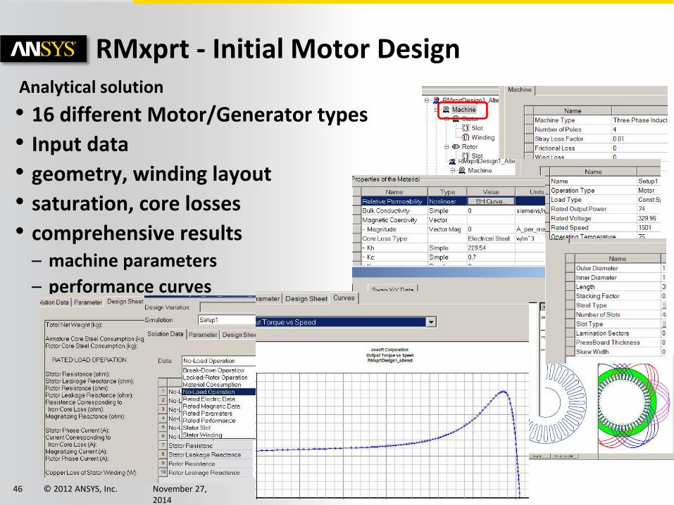
RMxprt - Initial Motor Design Analytical solution
• 16 different Motor/Generator types
• Input data
• geometry, winding layout
• saturation, core losses
• comprehensive results – machine parameters
– performance curves
© 2012 ANSYS, Inc. November 27, 2014
47
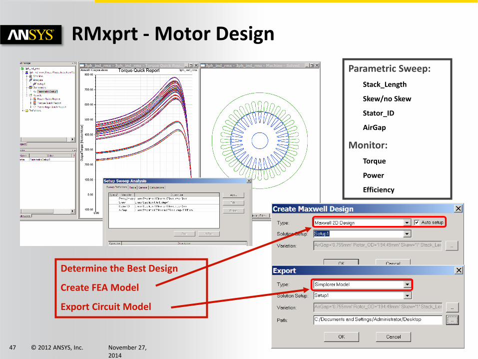
Parametric Sweep:
Stack_Length
Skew/no Skew
Stator_ID
AirGap
Monitor:
Torque
Power
Efficiency
Determine the Best Design
Create FEA Model
Export Circuit Model
RMxprt - Motor Design
© 2012 ANSYS, Inc. November 27, 2014
48
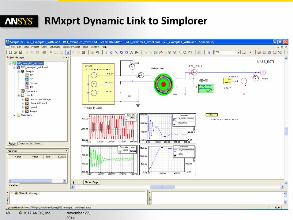
RMxprt Dynamic Link to Simplorer
© 2012 ANSYS, Inc. November 27, 2014
49
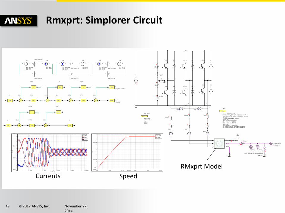
Rmxprt: Simplorer Circuit
0
0
0 0
0
C24700uF
IGBT1 IGBT2 IGBT3
IGBT4 IGBT5
IGBT6
D7 D8 D9
D10 D11
D12
ICA:
FML_INIT1
TP:=0.00005ustmax:=C1.Vt0a:=0t0b:=0t0c:=0
P11
SET: t0a:=timeSET: z4:=0SET: z1:=1
P12
SET: z4:=1SET: z1:=0
Time - t0a>=TEa
Time - t0a>=TP
EQU
FML1
theta_el:=SM_ROT1.PHI*Pole/2yalph:=cos(theta_el) * yd.VAL -sin(theta_el) *yq.VALybeta:=sin(theta_el) * yd.VAL + cos(theta_el) * yq.VALya:=yalphyb:=-0.5 * yalph + ybeta * sqrt(3)/2yc:=-ya - ybTEa:=(ya/ustmax + 1) * TP/2TEb:=(yb/ustmax + 1)*TP/2TEc:=(yc/ustmax + 1)*TP/2i1alph:=AM1.Ii1beta:=(AM1.I + 2*AM2.I)/sqrt(3)i1d1:=i1alph * cos(theta_el) + i1beta * sin(theta_el)i1q1:=i1beta * cos(theta_el) - i1alph * sin(theta_el)
CONSTn_ref
3600/60*pi*2
SUM1
GAIN
GAIN2
I
INTG1
SUM2
LIMIT
iq_refSUM3
GAIN
iq
I
INTG2
GAIN
GAIN1SUM4
LIMIT
yq
LIMIT
yd SUM5
GAIN
GAIN3
I
INTG3
GAIN
id_ref
SUM6
GAIN
id
Time - t0b>=TP
Time - t0b>=TEb
P22
SET: z5:=1SET: z2:=0
P21
SET: t0b:=timeSET: z5:=0SET: z2:=1
Time - t0c>=TP
Time - t0c>=TEc
P32
SET: z6:=1SET: z3:=0
P31
SET: t0c:=timeSET: z6:=0SET: z3:=1
+
V
VM1 +
V
VM2
r4 r5 r6
RMxprt
A
B
C
N
ROT1
ROT2
A
AM1
A
AM2
+
FSM_ROT1
w
+
VM_ROT1
MASS_ROT1
0.005kgm2
T
F_ROT1
(10+0.1*sin(2*pi*120*Time))*n.VAL/n_ref
A
AM3
C14700uF
r7
L40.0005H
L5
0.0005H
L6
0.0005H
GAINn
-VM_ROT1.OMEGA
R_ESR
R_ESR2
R8
E1
T
FM_ROT1
0.00 20.00 40.00 60.00 80.00 100.00Time [ms]-75.00
-25.00
25.00
75.00
Y1 [
A]
Curve Info
AM1.ITR
AM2.ITR
AM3.ITR
0.00 20.00 40.00 60.00 80.00 100.00Time [ms]
-18.85
0.00
100.00
200.00
300.00
400.00
Y1
Curve Info
n_ref.VALTR
n.VALTR
Speed Currents
RMxprt Model
© 2012 ANSYS, Inc. November 27, 2014
50
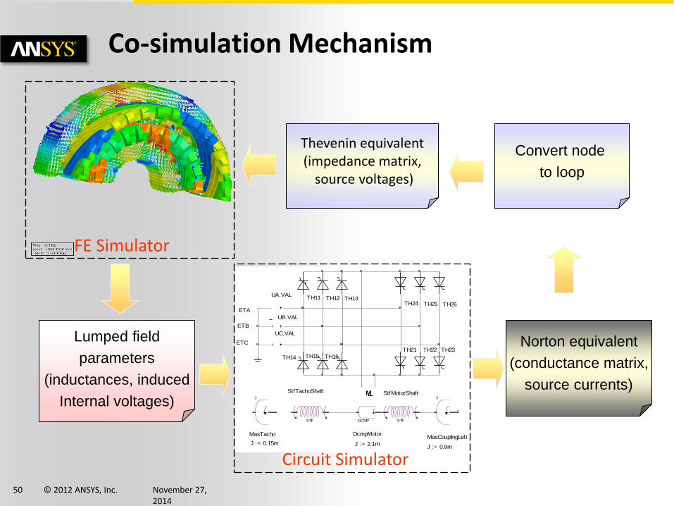
Co-simulation Mechanism
Thevenin equivalent (impedance matrix,
source voltages)
Lumped field
parameters
(inductances, induced
Internal voltages)
Norton equivalent
(conductance matrix,
source currents)
Convert node
to loop
FE Simulator
Mww
Rw
Ew J
STF
M
DCMP STF
J
ETA
UA.VAL
ETB
UB.VAL
ETC
UC.VAL
TH11 TH12 TH13
TH14 TH15 TH16
TH21 TH22 TH23
TH24 TH25 TH26
MasTacho
J := 0.15m
StfTachoShaft
DcmpMotor
J := 2.1m
StfMotorShaft
MasCouplingLeft
J := 0.9m
Circuit Simulator
© 2012 ANSYS, Inc. November 27, 2014
51
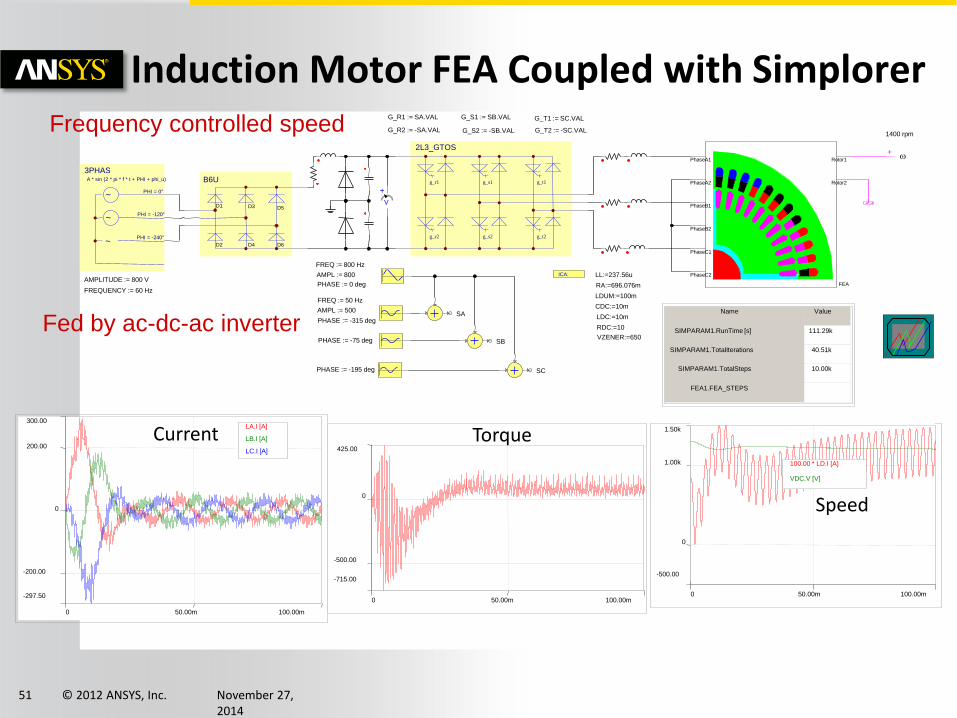
Induction Motor FEA Coupled with Simplorer
FEA
PhaseA1
PhaseA2
PhaseB1
PhaseB2
PhaseC1
PhaseC2
Rotor1
Rotor2
w +
ICA:
1400 rpm
LL:=237.56u
RA:=696.076m
B6U
D1 D3 D5
D2 D4 D6
2L3_GTOS
g_r1
g_r2
g_s1
g_s2
g_t1
g_t2
~
3PHAS
~
~
A * sin (2 * pi * f * t + PHI + phi_u)
PHI = 0°
PHI = -120°
PHI = -240°
LDUM:=100m
CDC:=10m
LDC:=10m
RDC:=10
VZENER:=650
AMPLITUDE := 800 V
FREQUENCY := 60 Hz
-297.50
300.00
-200.00
0
200.00
0 100.00m 50.00m
LA.I [A]
LB.I [A]
LC.I [A]
FREQ := 800 Hz
AMPL := 800
PHASE := 0 deg
AMPL := 500
PHASE := -315 deg
FREQ := 50 Hz
PHASE := -195 deg
PHASE := -75 deg
SA
SB
SC
G_R1 := SA.VAL
G_R2 := -SA.VAL
G_S1 := SB.VAL
G_S2 := -SB.VAL
G_T1 := SC.VAL
G_T2 := -SC.VAL
+
V
Name Value
SIMPARAM1.RunTime [s] 111.29k
SIMPARAM1.TotalIterations 40.51k
SIMPARAM1.TotalSteps 10.00k
FEA1.FEA_STEPS
-500.00
1.50k
0
1.00k
0 100.00m 50.00m
100.00 * LD.I [A]
VDC.V [V]
-715.00
425.00
-500.00
0
0 100.00m 50.00m
Current Torque
Speed
Fed by ac-dc-ac inverter
Frequency controlled speed
© 2012 ANSYS, Inc. November 27, 2014
52
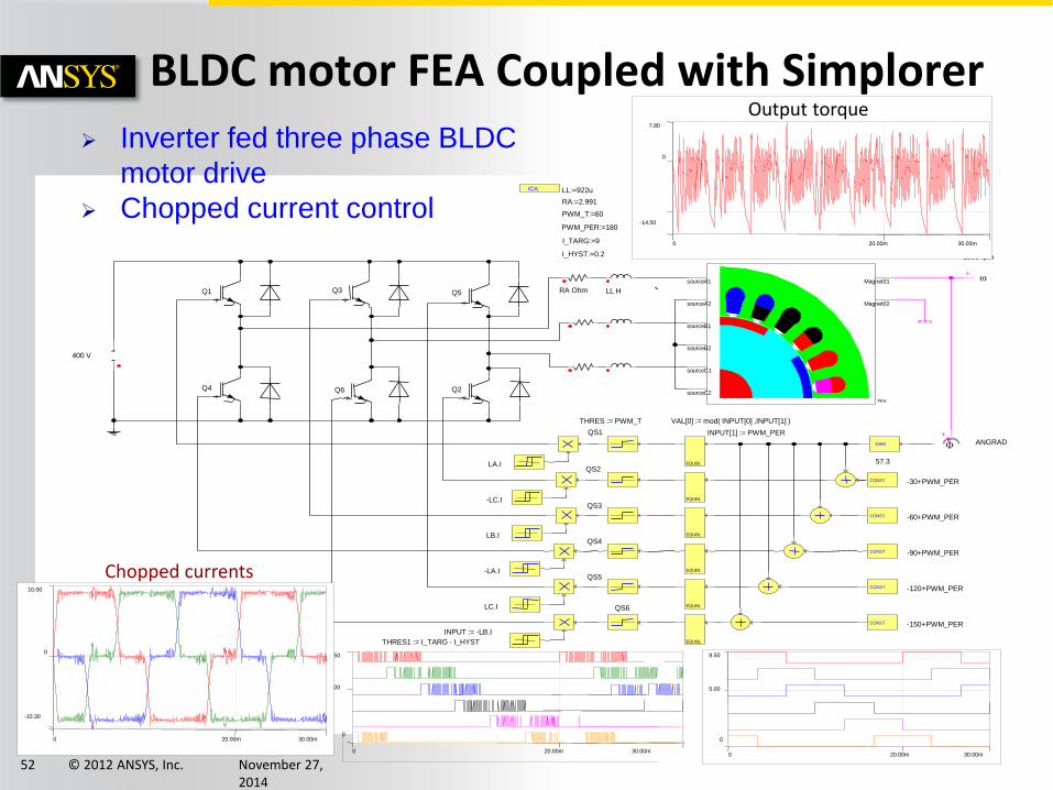
BLDC motor FEA Coupled with Simplorer
FEA
sourceA1
sourceA2
sourceB1
sourceB2
sourceC1
sourceC2
Magnet01
Magnet02
w +
ICA:
+
F GAIN
CONST
CONST
EQUBL
EQUBL
EQUBL
1500 rpm
LL:=922u
RA:=2.991
ANGRAD
57.3
-60+PWM_PER
-30+PWM_PER
QS1
QS2
QS3
VAL[0] := mod( INPUT[0] ,INPUT[1] )
PWM_T:=60
I_TARG:=9
I_HYST:=0.2
Q1
Q2
Q3 Q5
Q4 Q6
400 V
THRES := PWM_T
EQUBL
CONST
QS4
-90+PWM_PER
EQUBL
CONST
QS5
-120+PWM_PER
EQUBL
CONST
QS6
-150+PWM_PER
RA Ohm LL H
PWM_PER:=180
INPUT[1] := PWM_PER
INPUT := -LB.I
LC.I
-LA.I
LB.I
-LC.I
LA.I
THRES1 := I_TARG - I_HYST
0
8.50
5.00
0 20.00m 30.00m
-14.50
7.80
0
0 30.00m 20.00m
-10.30
10.00
0
0 30.00m 20.00m
Output torque
Chopped currents
Inverter fed three phase BLDC
motor drive
Chopped current control
0
8.50
5.00
0 30.00m 20.00m
© 2012 ANSYS, Inc. November 27, 2014
53
FEA
A1
A2
B1
B2
C1
C2
AirRotor1
AirRotor2
w +
26293 rpm ICA: LL:=70.6914u
RA:=203m
140 V
100u F
+
F ANGRAD GAIN
57.3
CONST -30+90
CONST -60+90
EQUBL
VAL[0] := mod( INPUT[0] ,90 ) QA
QB
QC
EQUBL
EQUBL
Name Value
FEA1.FEA_STEPS 1.00k
SIMPARAM1.RunTime [s] 6.90k
SIMPARAM1.TotalIterations 4.05k
SIMPARAM1.TotalSteps 1.00k
0
100.00
50.00
0 1.00m 500.00u
10.00 * QA.VAL
10.00 * QB.VAL + 30.00
10.00 * QC.VAL + 60.00
ROTA.VAL[0]
ROTB.VAL[0]
ROTC.VAL[0]
-54.00m
264.00m
0
100.00m
200.00m
0 1.00m 500.00u
10.00u * FEA1.OMEGA
V_ROTB1.TORQUE [Nm]
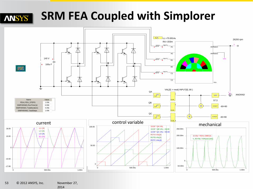
mechanical
-17.80
18.00
-10.00
0
10.00
0 1.00m 500.00u
L1.I [A]
L2.I [A]
L3.I [A]
E1.I [A]
current control variable
SRM FEA Coupled with Simplorer
© 2012 ANSYS, Inc. November 27, 2014
54
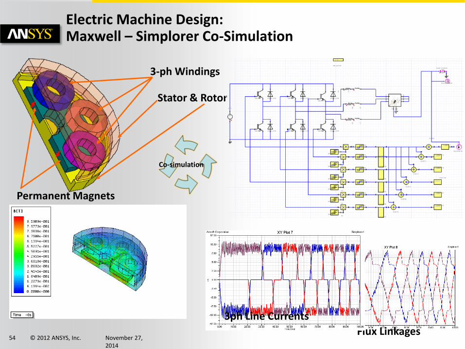
Electric Machine Design: Maxwell – Simplorer Co-Simulation
3-ph Windings
Permanent Magnets
Stator & Rotor
Flux Linkages
3ph Line Currents
Co-simulation
© 2012 ANSYS, Inc. November 27, 2014
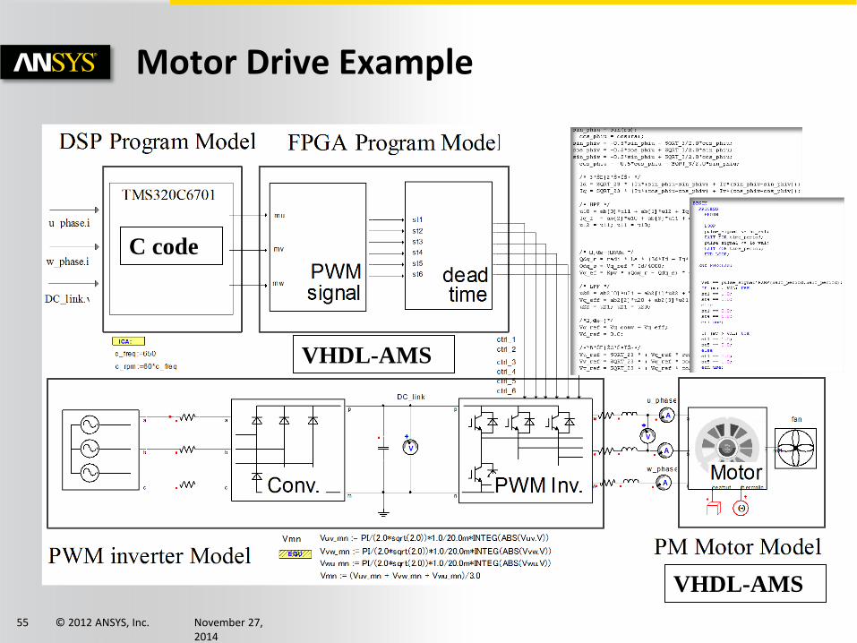
55
Motor Drive Example
C code
VHDL-AMS
VHDL-AMS
© 2012 ANSYS, Inc. November 27, 2014
56
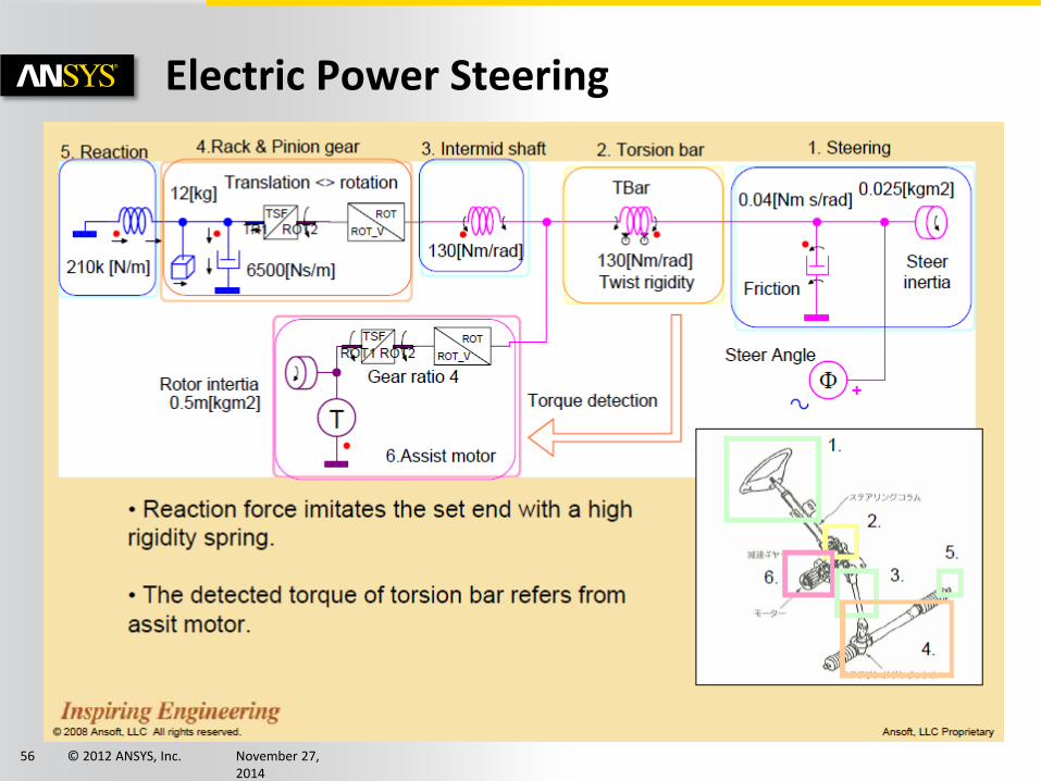
Electric Power Steering
© 2012 ANSYS, Inc. November 27, 2014
57
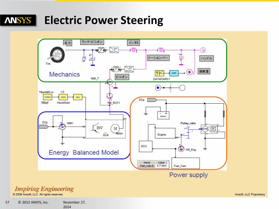
Electric Power Steering
© 2012 ANSYS, Inc. November 27, 2014
58
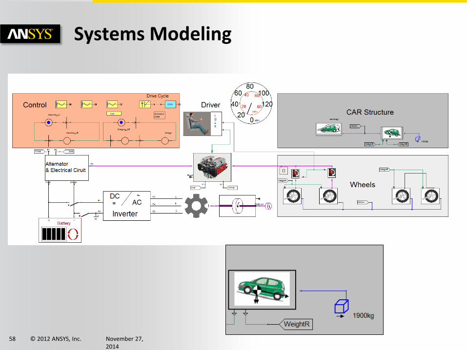
Systems Modeling
© 2012 ANSYS, Inc. November 27, 2014
59
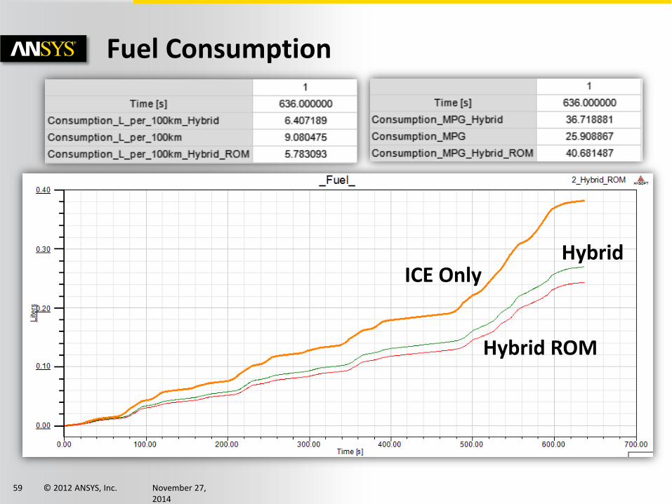
Fuel Consumption
ICE Only Hybrid
Hybrid ROM

© 2012 ANSYS, Inc. November 27, 2014
60
Register Now!
Early Bird Rate Saves $150 Off of Registration Cost
Register at www.ansys.com/ASWC
Automotive Simulation World Congress
© 2012 ANSYS, Inc. November 27, 2014
61
ANSYS Training
Interested in Live Training Sessions with ANSYS Experts? Training classes are offered both locally and online. View the entire schedule at: http://www.ansys.com/Support/Training+Center Topics include: • Introduction to ANSYS Mechanical • Introduction to ANSYS DesignModeler • Introduction to ANSYS FLUENT • Introduction to ANSYS Icepak • Introduction to ANSYS HFSS • Introduction to ANSYS Explicit Dynamics • Introduction to ANSYS ICEM CFD • And Many More…
© 2012 ANSYS, Inc. November 27, 2014
62
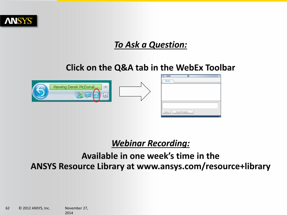
To Ask a Question:
Click on the Q&A tab in the WebEx Toolbar
Webinar Recording:
Available in one week’s time in the ANSYS Resource Library at www.ansys.com/resource+library
© 2012 ANSYS, Inc. November 27, 2014
63
Thank you